1
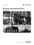
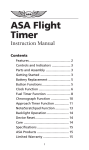
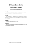
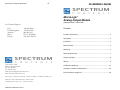
MicroLogix™ Analog Output Module 24 Installation Guide MicroLogix™ Analog Output Module (Catalog Number 1762sc-OF8) For Technical Support USA United Kingdom Australia Brazil Europe 440-646-6900 01908 635230 1800-809-929 (55) 11 3618 8800 (49) 2104 960 630 Contents For More Information ............................................................................... 2 Description ................................................................................................ 3 Installation ................................................................................................ 4 Remove Power .......................................................................................... 5 Mounting ................................................................................................... 5 Power Requirements ................................................................................ 7 System Assembly ...................................................................................... 8 Wiring ........................................................................................................ 9 1705 132nd Ave NE Bellevue, WA 98005 USA Tel: 425-746-9481 Fax: 425-641-9473 Email: [email protected] Web: www.spectrumcontrols.com Environnements dangereux .................................................................... 20 MicroLogix is a trademark of Rockwell Automation. Belden is a trademark of Belden, Inc. Publication 1762sc-OF8 Install Guide – February 2009 © 2009 Spectrum Controls, Inc. Printed in the USA. Publication 0100163-01 Rev. B I/O Memory Mapping ............................................................................. 12 Hazardous Location Considerations ........................................................ 19 2 MicroLogix™ Analog Output Module MicroLogix™ Analog Output Module ForMoreInformation For An overview of the MicroLogix 1200 system, including information on controllers and expansion I/O. Information on installing, wiring, and operating a MicroLogix 1200 Programmable Controller Installation guide for the MicroLogix 1200 Programmable Controller. More information on proper wiring and grounding techniques. Refer to this Document MicroLogix™ 1200 System Overview Allen-Bradley Pub. No. 1762-SO001AUS-P MicroLogix 1200 Programmable Controllers User Manual 1762-UM001BUS-P MicroLogix 1200 Programmable Controllers Installation Instructions Industrial Automation Wiring and Grounding Guidelines 1762-IN006CMU-P Intentionally Left Blank 1770-4.1 If you would like a manual, you can download a free electronic version from the internet: www.spectrumcontrols.com Publication 0100163-01 Rev. B Publication 0100163-01 Rev. B 23 MicroLogix™ Analog Output Module 22 MicroLogix™ Analog Output Module Description Intentionally Left Blank Publication 0100163-01 Rev. B Publication 0100163-01 Rev. B 3 4 MicroLogix™ Analog Output Module MicroLogix™ Analog Output Module Installation 1762 I/O is suitable for use in an industrial environment when installed in accordance with these instructions. Specifically, this equipment is intended for use (1) in clean, dry environments (Pollution degree 2 ) and to circuits not exceeding (2) (3) Over Voltage Category II (IEC 60664-1). Prevent Electrostatic Discharge Electrostatic discharge can damage integrated circuits or semiconductors if you touch bus connector pins. Follow these guidelines when you handle the module: Intentionally Left Blank Touch a grounded object to discharge static potential. Wear an approved wrist-strap grounding device. Do not touch the bus connector or connector pins. Do not touch circuit components inside the module. If available, use a static-safe work station. When not in use, keep the module in its staticshield box. (1) Pollution Degree 2 is an environment where, normally, only non-conductive pollution occurs except that occasionally a temporary conductivity caused by condensation shall be expected. (2) Over Voltage Category II is the load level section of the electrical distribution system. At this level transient voltages are controlled and do not exceed the impulse voltage capability of the product’s insulation. (3) Pollution Degree 2 and Over Voltage Category II are International Electrotechnical Commission (IEC) designations. Publication 0100163-01 Rev. B Publication 0100163-01 Rev. B 21 MicroLogix™ Analog Output Module 20 Environnementsdangereux Cet équipement est conçu pour être utilisé dans des environnements de Classe 1, Division 2, Groupes A, B, C, D ou non dangereux. La mise en garde suivante s’applique à une utilisation dans des environnements dangereux. DANGER D’EXPLOSION La substitution de composants peut rendre cet équipement impropre à une utilisation en environnement de Classe 1, Division 2. Ne pas remplacer de composants ou déconnecter l'équipement sans s'être assuré que l'alimentation est coupée. Ne pas connecter ou déconnecter des composants sans s'être assuré que l'alimentation est coupée. Ce produit doit être installé dans une armoire. Pour les applications de Classe I, Division 2, le connecteur de bus doit être correctement installé et son couvercle enclenché. Pour les applications de Classe 1, Division 2, tous les modules doivent être installés en contact direct les uns avec les autres, comme indiqué page6. Si on utilise le montage sur rail DIN, une butée doit être placée à l'avant de l'automate et après la dernière unité d'E/S 1762. Publication 0100163-01 Rev. B MicroLogix™ Analog Output Module 5 RemovePower Remove power before removing or installing this module. When you remove or install a module with power applied, an electrical arc may occur. An electrical arc can cause personal injury or property damage by: sending an erroneous signal to your system’s field devices, causing unintended machine motion causing an explosion in a hazardous environment causing permanent damage to the module’s circuitry Electrical arcing causes excessive wear to contacts on both the module and its mating connector. Worn contacts may create electrical resistance. Mounting The 1762sc-OF8 is to be used with the MicroLogix™ 1100, 1200 or 1400 processor. Do not remove protective debris strip until after the module and all other equipment near the module is mounted and wiring is complete. Once wiring is complete and the module is free of debris, carefully remove protective debris strip. Failure to remove strip before operating can cause overheating. Publication 0100163-01 Rev. B MicroLogix™ Analog Output Module 6 Minimum Spacing Maintain spacing from enclosure walls, wireways, adjacent equipment, etc. Allow 50.8 mm (2 in.) of space on all sides for adequate ventilation, as shown MicroLogix™ Analog Output Module 19 HazardousLocationConsiderations This equipment is suitable for use in Class I, Division 2, Groups A, B, C, D or nonhazardous locations only. The following WARNING statement applies to use in hazardous locations. EXPLOSION HAZARD 1762 expansion I/O may be mounted horizontally only. During panel or DIN rail mounting of all devices, be sure that all debris (metal chips, wire strands, etc.) is kept from falling into the module. Debris that falls into the module could cause damage when power is applied to the module. DINRailMounting The module can be mounted using the following DIN rails: 35 x 7.5 mm (EN 50 022 - 35 x 7.5) or 35 x 15 mm (EN 50 022 - 35 x 15). Before mounting the module on a DIN rail, close the DIN rail latch. Press the DIN rail mounting area of the module against the DIN rail. The latch will momentarily open and lock into place. Use DIN rail end anchors (Allen-Bradley part number 1492-EA35 or 1492EAH35) for environments with vibration or shock concerns. Publication 0100163-01 Rev. B Substitution of components may impair suitability for Class I, Division 2. Do not replace components or disconnect equipment or change the current switch selection switch position unless power has been switched off. Do not disconnect equipment unless power has been removed or the area is known to be nonhazardous. This product must be installed in an enclosure. In Class I, Division 2 applications, the bus connector must be fully seated and the bus connector cover must be snapped in place. In Class I, Division 2 applications, all modules must be mounted in direct contact with each other as shown on page 6. If DIN rail mounting is used, an end stop must be installed ahead of the controller and after the last 1762 I/O module. All wiring must comply with N.E.C. article 5014(b). Publication 0100163-01 Rev. B MicroLogix™ Analog Output Module Specification Fast Transient Burst (IEC61000-4-4) Surge Immunity (IEC61000-4-5) Conducted Immunity (IEC61000-4-6) 18 10V, 0.15 to 80 MHz Output Specifications Specification Accuracy - Voltage Outputs Accuracy - Current Outputs Output Resolution (at 25C) Voltage Output Current Output Differential Nonlinearity Output Ripple Output Impedance Output Load Maximum Output Inductive and Capacitive Load Output Settling Time Output Channel glitch. Short Circuit Protection 7 For environments with extreme vibration and shock concerns, use the panel mounting method described below, instead of DIN rail mounting. 2 kV Line - Line, 4 kV Line - Gnd Output Protection MicroLogix™ Analog Output Module Description 4 kV Description System accuracy at 25° C: ± 20 mV maximum System accuracy at -20-60°C: ± 50 mV maximum System accuracy at 25° C: ± 50 uA maximum System accuracy at -20-60°C: ± 75 uA maximum In RAW mode 370µV per bit average when using RAW format in ±10V range and 0-10V range 185µV per bit average when using RAW format in 0-5 or 1-5V ranges 380nA per bit when using RAW format for all current ranges ±1 LSB <15mV ripple for voltage or current Current: >1Megohm, Voltage: <1 ohm (MRD) Current: 0 ohm min, 500 ohm max, Voltage: >=1k ohm at 10V output (10 mA), includes wire resistance. 0.1mH 1µF <1ms to 63% of full scale Current mode = < ± 1V for 20ms at maximum load Voltage mode = < ± 0.4V for 20ms and < ±- 1V for 1.5ms with 1k ohm load ±24V @25dec C for 1 minute on any channel, with any range and value Yes, continuous. (IEC 1131-2 requirement) with any range and value PanelMounting Use the dimensional template shown below to mount the module. The preferred mounting method is to use two M4 or #8 panhead screws per module. M3.5 or #6 panhead screws may also be used, but a washer may be needed to ensure a good mechanical contact. Mounting screws are required on every module. PowerRequirements The maximum number of OF8 modules that can be installed in a system depends on the maximum bus current draw of the module and the maximum bus current provided by the PLC. The OF8 module has the following power requirements. 5 VDC 24 VDC 30 mA 250 mA @ 18.7 V, 195 mA @ 24 V Use the table below to determine the maximum number of OF8 modules that can be installed in a MicroLogix system. Publication 0100163-01 Rev. B Publication 0100163-01 Rev. B 8 MicroLogix™ Analog Output Module MicroLogix™ Analog Output Module 17 Specifications Controller ML1100 ML1200 (24pt.) ML1200 (40pt.) ML1400 Max 5V Bus Current (mA) 800 Max 24V Bus Current (mA) 700 Max # of OF8 Modules 3 400 350 1 600 500 2 1500 1500 6 SystemAssembly General Specifications Specification Isolation Withstand Channel to Rack Output channel to channel Power Requirements Internal rack +5V Internal rack +24V Heat Dissipation Maximum number of modules on the bus The expansion I/O module is attached to the controller or another I/O module by means of a ribbon cable after mounting as shown below. Fusing Wire Size Wire Type Dimensions Use the pull loop on the connector to disconnect modules. Do not pull on the ribbon cable. Storage Temperature Operating Temperature Operating Humidity Vibration Shock Weight, unpackaged Weight, packaged Module Identification Vendor I.D. Product Type Product Code Certifications Agency Certification Hazardous Environment Class Radiated and Conducted Emissions Electrical /EMC: ESD Immunity (IEC61000-4-2) Radiated Immunity (IEC61000-4-3) Publication 0100163-01 Rev. B Description 707 VDC for 1 minute (withstand voltage) Optical & magnetic Return lines are connected together. No isolation between channels. 30 mA maximum 250 mA maximum at 18.7V, 195mA max at 24V. 4.9W total Max Distance rating of 6. Maximum number of modules by controller type: Max 5V Max 24V Max # of Controller Bus Current Bus Current Modules ML1100 800 700 3 ML1200 (24pt.) 400 350 1 ML1200 (40pt.) 600 500 2 ML1400 1500 1500 6 None Up to two wires of size #14-#22 AWG (solid) or #16- #22 AWG (stranded) To ensure proper operation and high immunity to electrical noise, always use Belden 8761 (shielded, twisted pair) or equivalent wire for voltage and current sensors 90 mm (height) x 87 mm (depth) x 40 mm (width)height including mounting tabs is 110 mm. 3.54 in. (height) x 3.43 in (depth) x 1.58 in (width)height including mounting tabs is 4.33 in. -40˚C to +85˚C (-40˚F to 185˚F) -20˚C to 60˚C (-4˚F to +140˚F) 5% to 95% non-condensing Operating: 10 to 500 Hz, 5G, 0.030 in. max peak-to-peak Operating: 30G 0.185 kg (0.408 lb) (TBD) 0.299 kg (0.615 lb) (TBD) 58 10 21 C-UL listed (under CSA C22.2 No. 142) UL 508 listed CE compliant for all applicable directives Class I, Division 2, Hazardous Location, Groups A, B, C, D (ISA 12.12.01, C-UL under CSA C22.2 No. 213) Operating Temperature Code T6 IEC61000-6-4 FCC Part 15B Class A The module has passed testing at the following levels: 4 kV contact, 8 kV air 10 V/m, 80 to 1000 MHz, 80% amplitude modulation, 900 MHz & 1890 MHz 100% amplitude modulation Publication 0100163-01 Rev. B 16 MicroLogix™ Analog Output Module To Select 7 Data Format Scaled for PID 4 0 3 0 Engineering Units 0 1 Percent Range 1 0 Raw/Proportional Data 1 1 Unused MicroLogix™ Analog Output Module 0 6 0 5 2 1 9 EXPLOSION HAZARD Make these bit settings 0 • In Class I, Division 2 applications, the bus connector must be fully seated and the bus connector cover must be snapped in place. • In Class I, Division 2 applications, all modules must be mounted in direct contact with each other as shown on page 6. If DIN rail mounting is used, an end stop must be installed ahead of the controller and after the last 1762 I/O module. 0 Wiring GroundingtheModule Grounding for this product is provided by the MicroLogix™ 1100, 1200 or 1400 CPU via the bus ribbon cable. Refer to Industrial Automation Wiring and Grounding Guidelines, Allen-Bradley publication 1770-4.1, for additional information. System Wiring Guidelines Consider the following when wiring your system: Publication 0100163-01 Rev. B The analog common (COM) is not connected to earth ground inside the module. All terminals are electrically isolated from the system. Use Belden™ 8761, or equivalent, shielded wire. Under normal conditions, the drain wire (shield) should be connected to the metal mounting panel (earth ground) as close to the module as possible. Keep the shield connection to earth ground as short as possible. To ensure optimum accuracy for voltage type outputs, limit overall cable impedance by keeping all analog cables as short as possible. Locate the I/O system as close to your voltage type sensors or actuators as possible. Digital and analog power must be supplied by an Isolated Secondary Limited Energy Low Voltage source. Use supply wires for 20˚ C above surrounding ambient. Publication 0100163-01 Rev. B MicroLogix™ Analog Output Module 10 15 MicroLogix™ Analog Output Module Commands Terminal Block Layout Command Unlock 0xFFF0 Clear Command 0xFF00 Load Config 0xFFF1 Exit 0xFF80 3) Grounding the cable shield at the module end only usually provides sufficient noise immunity. However, for best cable shield performance, earth ground the shield at both ends, using a 0.01µF capacitor at one end to block AC power ground currents, if necessary. Value Description This MUST be the first command issued after entering Command Mode. If not, an error will be posted. Data Words are ignored. The module does not need to detect a command transition to Unlock. It simply waits for the Fixed Words to be valid and Unlock command set. This command is ignored if issued multiple times (Response Code will be 0). Once Command Mode is unlocked it remains unlocked until it has been successfully configured and the Exit command issued. Clears the command buffer to allow a command to be reissued. Since the module only knows a command is issued when the Command word changes, the only way to re-issue a command is to cause a transition. This command gives the user a null command to do that. The response is always 0. No other action is taken with this command. Data Words 1-4 must contain valid channel configuration data for all channels. See Data Words table below. Configuration will be validated. An error will be posted for the first invalid channel configuration found. If the configuration is invalid, the configuration info in the Data Words may be modified but to re-issue the Load Config, the Clear Command must be issued first. Delay 600ms then enter run state with configuration. The delay begins after the response. If configuration is not valid, the module will remain in Command Mode until a valid configuration is entered. Data Words 1-4: If the command requires valid data in the Data Words, they are validated and a response is placed in the Response Code register (i.e. Word I:e.1). The following table lists the possible configuration settings for each of the 8 channels. Each Data Word contains two channel configurations. See Output Data File table for Data Word layout. Data Words 1-4 To Select Labeling the Terminals A write-on label is provided with the module. Remove the label from the door, mark the identification of each terminal with permanent ink, and slide the label back into the door. Publication 0100163-01 Rev. B Make these bit settings 7 Output Type 4 to 20 mA 2 0 1 0 0 0 0 to 20 mA 0 0 1 -10 to 10 V 0 1 0 0 to 10 V 0 1 1 1 to 5 V 1 0 0 0 to 5 V 1 0 1 Reserved 1 1 0 Channel Disabled 1 1 1 Publication 0100163-01 Rev. B 6 5 4 3 MicroLogix™ Analog Output Module 14 MicroLogix™ Analog Output Module 11 Once the module detects the transition from Program to Run it waits until the Fixed Words and Command code are set to valid values. The first command must be Unlock. If an error is detected, a non-zero response will be placed in the Response Code (see Input Data File table). Keep in mind the module is constantly polling the output file as it is updated by the controller. The module will validate each command using the following three step process: 1) 2) Validate Fixed Words 1-3: These words must always be valid during Command Mode. An error will be posted in the Response Code until these are correct. Commands will not be validated and processed until these words are set correctly. The fixed words are posted above in the Output Data File table. Validate Command: If the Fixed Words are valid, the Command word will be checked. If it is not set to a valid command, an error will be reported. Initially the module only checks for the Unlock command. After the Unlock command is detected, the module must detect a transition in the Command word to trigger a new command. Wiring the Finger-Safe Terminal Block Be careful when stripping wires. Wire fragments that fall into a module could cause damage when power is applied. Once wiring is complete, ensure the module is free of all metal fragments. When wiring the terminal block, keep the finger-safe cover in place. 1. Route the wire under the terminal pressure plate. You can use the stripped end of the wire or a spade lug. The terminals will accept a 6.35 mm (0.25 in.) spade lug. 2. Tighten the terminal screw making sure the pressure plate secures the wire. Recommended torque when tightening terminal screws is 0.904 Nm (8 in-lbs). 3. After wiring is complete, remove the debris shield. If you need to remove the finger-safe cover, insert a screw driver into one of the square wiring holes and gently pry the cover off. If you wire the terminal block with the finger-safe cover removed, you will not be able to put it back on the terminal block because the wires will be in the way Publication 0100163-01 Rev. B Publication 0100163-01 Rev. B 12 MicroLogix™ Analog Output Module Wire Size and Terminal Screw Torque Each terminal accepts up to two wires with the following restrictions: Wire Type Solid Stranded Wire Size Cu-90°C (194°F) Cu-90°C (194°F) #14 to #22 AWG #16 to #22 AWG Terminal Screw Torque 0.904 Nm (8 in-lbs) 0.904 Nm (8 in-lbs) 13 MicroLogix™ Analog Output Module Input Data File For each module, slot x, input words 0 through 7 contain module status information including channel status and configuration status. During module configuration, the module enters a special mode called Command Mode. During Command Mode, configuration data is written to the module using the output data file and Command Mode response data is returned to words 0 through 2 in the input data file. After the Command Mode process completes, the module returns to normal run mode. The table below shows the layout for each word during both modes of operation. Input Data File I/OMemoryMapping Addressing The addressing scheme for 1762 Expansion I/O is shown below. I:e.0 I:e.1 I:e.2 I:e.3 I:e.4 I:e.5 I:e.6 I:e.7 Input File(Read Only) Normal Run Mode Command Mode General Status Word 0 Command Echo Output Status Word 1 (ch 0-3) Response Code Output Status Word 2 (ch 4-7) Response Channel Echo Config (ch 0-1) Echo Config (ch 2-3) Echo Config (ch 4-5) Echo Config (ch 6-7) Not Used Configuration Data File The configuration data file is not used. Instead the output data file is used to configure the module and control output channels 0 through 7. Output Data File (1) I/O located on the controller (embedded I/O) is slot 0. I/O added to the controller (expansion I/O) begins with slot 1. This section describes how the input and output files are used together to configure the module. The module enters a special mode called Command Mode when the PLC transitions from Program mode to Run mode. After the module enters Command Mode, the output file is used to send commands to the module and the module responds via the input data file. The table below shows the layout for each word during both modes of operation. Output Data File O:e.0 O:e.1 O:e.2 O:e.3 O:e.4 O:e.5 O:e.6 O:e.7 Publication 0100163-01 Rev. B Output File Normal Run Mode Channel 0 Data Word Channel 1 Data Word Channel 2 Data Word Channel 3 Data Word Channel 4 Data Word Channel 5 Data Word Channel 6 Data Word Channel 7 Data Word Publication 0100163-01 Rev. B Command Mode Command Data Word 1 (Ch0 & 1) Data Word 2 (Ch2 & 3) Data Word 3 (Ch4 & 5) Data Word 4 (Ch6 & 7) Fixed Word 1 (0xCDEF) Fixed Word 2 (0xFEDC) Fixed Word 3 (0x5A5A)