1
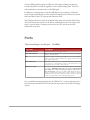
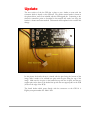
GPS Upgrade Kit for IN-14 Nixie Clock General Instructions v1.0b Instructions for Adding a Garmin GPS 18 LVC to a IN-14 Nixie Clock 2007 Peter J. Jensen, LLC Ann Arbor, MI Scary Warning DANGER: BUILDING OR MODIFYING THIS KIT INVOLVES WORKING WITH DANGEROUS, POTENTIALLY LETHAL VOLTAGES. POWER LINE VOLTAGES ARE DANGEROUS. IF YOU ARE NOT EXPERIENCED WORKING WITH DANGEROUS, POTENTIALLY LETHAL VOLTAGES, RETURN THE KIT FOR A REFUND. IF YOU DO NOT ACCEPT FULL RESPONSIBILITY FOR WORKING WITH THESE POTENTIALLY LETHAL VOLTAGES, RETURN THE KIT FOR A REFUND. BY BUILDING OR MODIFYING THIS KIT, YOU ACKNOWLEDGE AND AGREE THAT PETER J. JENSEN, LLC, AND ITS MEMBERS, BEAR NO RESPONSIBILITY (OR AS LITTLE AS IS PERMISSIBLE BY LAW) FOR ANY HARM TO PERSON, PROPERTY, OR ANYTHING ELSE ANYBODY CAN THINK OF, DUE TO YOU WORKING WITH THESE DANGEROUS, POTENTIALLY LETHAL VOLTAGES OR BUILDING THIS KIT. Overview A man with a watch knows what time it is. A man with two watches is never sure. - Segal's Law This document describes how to connect a Garmin GPS 18 LVC to the IN-14 Nixie Tube Clock from tubeclock.com. The GPS unit will allow the clock to set and maintain time display to sub-millisecond accuracy. Timing accuracy comes from the GPS receiver in the Garmin GPS 18 hardware. The GPS 18 receives signals from the network of satellites which orbit the Earth and transmit accurate time codes via radio waves. These time codes are typically used for calculating position for navigational purposes, but they also provide a highly reliable time source. GPS Advantages and Disadvantages The advantages of GPS time synchronization include a high degree of accuracy over long periods of time (it is referenced to atomic clocks), and it's ubiquitous availability anywhere on the Earth. The disadvantage is that the signal is very weak, so the GPS 18 hardware should be placed in a position where it has a line of site view of the sky. The unit will work indoors, but at least placing it on a window sill is a good idea. Even thin material, like paper, will effect the receiver's performance. The Garmin GPS 18 LVC has a magnetic base, and also a screw to help with mounting. Search on amazon.com or the web for part numbers 010-10541-00 (suction cup mount) or 010-10453-00 (flange mount) if you would like mounting hardware for the GPS 18 LVC. Operation The Nixie Clock will communicate to the GPS-18 via two mechanisms: first is an RS232 serial port for communicating the time and setup information; and second is a Pulse Per Second (PPS) signal which will keep the clock in sync when the serial communications are not in use. A copy of the complete GPS-18 manual can be found on the Garmin website: http://www.garmin.com/manuals/425_TechnicalSpecification.pdf When the clock is turned on, the GPS will take from a few seconds to five minutes to acquire the satellites' signal. During this time, the clock will run using it's on-board oscillator, and you will need to set it to within 15 minutes of the correct time. This is necessary because the GPS system does not provide time zone information. When the signal is acquired, the GPS will send a signal to the clock (by beginning strobing of the PPS line) and the clock will then read the next serial port message and adjust the time. Once the PPS signal has begun, the GPS unit will continue sending one pulse per second until power is turned off, regardless of the satellite tracking state. The clock will synchronize its second counter to this PPS signal. In addition to setting the time on the first PPS signal, every morning at 2:45am the clock will query the GPS unit over the serial line. It will adjust the clock to the nearest half-hour offset of the UTC time provided from the GPS. The GPS provides the Universal Coordinated Time (same as Greenwich Mean Time). The clock assumes the user has set the time to within half an hour of the correct local time (i.e., plus or minus 15 minutes) and uses the the UTC time from the GPS calculate the exact time. Parts The first rule to tinkering is to save all the parts. -- Paul Erlich Part Name Description PIC16F688 Microcontroller Updated microcontroller with support for GPS 1 Watt, 100Ohm Resistor Replaces ½ Watt, 1k Ohm Resistor R1. This will allow more 5V power supply current to power the GPS-18 Wire Optional, to connect nixie decimal point display to AUX_A or AUX_B driver output. This will cause the nixie decimal point to light up a Pulse Per Second (PPS) signal is being received Garmin GPS 18 LVC The GPS antenna and receiver on a 5 meter cable. Make sure the GPS-18 has a view of the sky, as unobstructed as possible. It will work indoors, but at least placing the unit on a window sill is a good idea. 12V DC Power Adapter The 12V power adapter included with the GPS upgrade kit is a switch-mode power supply. WARNING: Please make sure to use the GPS modified clock ONLY with a switch-mode 12V power adapter, a 12V battery, or other true 12V source. The 12V power adapter which shipped with the nonGPS kit is transformer-based, and provides too high a Voltage for the GPS modified clock. The transformer-based power adapter can actually output up to about 18V, which will burn out the 100Ohm dropping resistor. If you would like mounting hardware for the GPS 18 LVC, search on amazon.com or the web for part numbers 010-10541-00 (suction cup mount) or 010-10453-00 (flange mount). How To Connect The GPS Furious activity is no substitute for understanding. -H. H. Williams These instructions assume that you are adding the GPS upgrade to a completed IN-14 nixie clock kit purchased through tubeclock.com. If you are adding the upgrade at the same time as building the kit, you will not need to remove the standard parts. Simply substitute the parts that came with the GPS upgrade kit instead. If you purchased a completed IN-14 nixie clock, you may use these instructions to upgrade the clock yourself. 1) To provide sufficient current for the GPS unit, resistor R1 will need to be replaced. This resistor was a ½ Watt 1k Ohm part, located on the right hand side of the PCB. Remove R1 and replace it with the 1 Watt, 100 Ohm part provided. 2) There are six wires which lead to the GPS-18. Each of these wires connects to a solder pad on the Nixie Clock circuit board. Snip off the connector provided on the GPS-18, strip the wire ends, and solder them to the pads on the clock PCB as listed in the table below. Yellow GPS 18 Pin # Color Signal Name Wire Gauge Connection Point on Clock 1 Yellow Pulse Per Second Output 28 RA0 2 Red Vin – 5V Power In 26 5V_A 3 Black Ground 28 GND_A 4 White GPS Serial Transmit 28 RC1 5 Black Ground 26 GND_A 6 Green GPS Serial Receive 28 RC0 Black (two wires) Green White Red Replace Microcontroller Replace R1 with 100Ohm 1W 3) Gently pry the old microcontroller from the socket, and insert the new PIC16F688. 4) Finally, the 12V DC power adapter will need to be replaced. WARNING: the 12V power adapter which shipped with the non-GPS kit is transformer based, and provides too high a Voltage for the GPS modified clock. The transformer based power adapter can actually output up to about 18V, which will burn out the 100Ohm dropping resistor. Please make sure to use the GPS modified clock ONLY with a switchmode 12V power adapter, a 12V battery, or other true 12V source. The 12V power adapter included with the GPS upgrade kit is a switch-mode power supply which will work without problems. Jumper Wire New 100Ohm, 1Watt Resistor R1 Optional PPS Active Indicator 5) Optionally, although recommended, you may wish to run a jumper wire from the AUX_A pad to the decimal point indicator on the seconds nixie. This will light up the decimal point on the right hand nixie as long as PPS signal has been received from the GPS within the last second. Remember that the GPS takes about five minutes to get synchronization on power-up before the PPS signal will be received. The decimal point pins on the nixies are directly to the left and right of the bottommost pin- approximately in the 5 o'clock and 7 o'clock positions. You can use any decimal point you wish as the indicator. The AUX_B pad can also be used, except this pad will toggle on or off each time a new pulse is received on the PPS line. The effect of connecting to the AUX_B pad is the indicator will turn on for a second, then off for a second, and then repeat so long as the PPS signal is active. If the PPS signal stops, the AUX_B connected indicator will maintain it's last state. Conclusion A conclusion is the place where you got tired of thinking. - Harold Fricklestein When you power up the GPS modified clock, with the GPS plugged into it, it will at first appear and function as it did without the GPS. Set the time to within 15 minutes, and let the clock run. When the GPS acquires the satellite signal, the time displayed will correct itself, and stay locked onto the GPS PPS output from then on. Additionally, every morning, at 2:45am local time, the clock will recheck that it has the correct time according to the GPS unit. If you connected the jumper wire to one of the nixie decimal places, it will light up to indicate that the GPS has synchronization and is sending PPS signals If the GPS does not acquire synchronization within five minutes, you may need to move the GPS antenna to a location closer to a window, or away from obstructions. I hope you enjoy your GPS upgrade. If you have trouble with the unit, please contact me, Peter Jensen, at [email protected]. Update The new revision of the the PCB has a place to put a header to mate with the connector which is already on the GPS unit. The surface mount header is shown in the picture below, and is now included with the GPS upgrade kit. Connecting to the thru-hole connection points as described in this manual still works, but using the header is a cleaner and easier method. This manual will be updated soon to reflect this change. In this picture the header shown is oriented with the pins facing the bottom of the image, while it needs to be soldered into place with the pins facing the top of the image. Make sure the six pins on the header line up with the six pads, and the two support pins on the front of the header line up with the two support pads on the PCB (closest to the edge of the PCB). The board header which mates directly with the connector on the GPS 18 is Digikey.com part number 455-1806-1-ND.