1
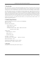
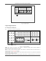
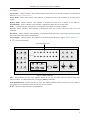
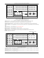
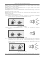
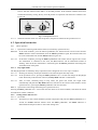
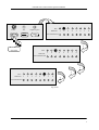
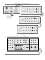
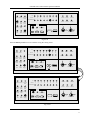
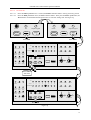
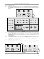
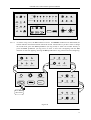
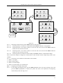
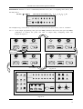
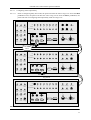
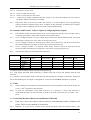
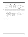
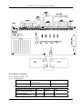
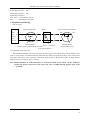
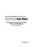
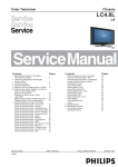
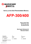
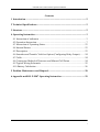
GST108 Zone Control Panel Operation Manual Contents 1 Introduction ........................................................................................................ 2 2 Technical Specifications ..................................................................................... 2 3 Structure.............................................................................................................. 2 4 Operating Instruction ........................................................................................ 3 4.1 Instruction of indicators ................................................................................. 3 4.2 Operation Instruction...................................................................................... 7 4.3 Instruction of Operating States..................................................................... 23 4.4 Internal Buzzer ............................................................................................. 23 4.5 Description ................................................................................................... 23 4.6 Sounders and Transfer Volt-free Option (Configuring Relay Output)......... 24 4.7 Cable............................................................................................................. 24 4.8 Connection Method of Detectors and Manual Call Points .......................... 24 4.9 Typical Wiring Schematic ............................................................................ 25 4.10 Battery Calculation..................................................................................... 26 5 Problem Maintenance and Disposal ............................................................... 28 6 Appendix―AEOL P-9907 Operating Instruction......................................... 29 GST108 PROCESSOR CONTROLLED CONVENTIONAL FIRE PANEL 1 GST108 Zone Control Panel Operation Manual 1 Introduction This control panel is a zone fire control panel developed with a SCM. It can monitor 8 zones at most, and each zone can be connected with up to 20 conventional fire detectors. It has 6 output points to control audible warning devices, such as sounder-beacons, alarm bells etc with the most load including 4 sounders outputs and a status output. This panel is self-contained with internal standby power supply and space provision for the two sealed lead-acid batteries. Its functions are microprocessor controlled, including test and isolate functions, day and night mode working. It has the functions of normal indication, fault indication, alarming indication and warning of short circuit and open circuit. It can also mark the position of the detection zone. The panel remains a port for a fire repeater panel for multi-zone fire indication. And it is easy to install and operate. By a keyswitch, it can enable the control function; by a keyswitch and an internal switch, it can enable the programming function. 2 Technical Specifications Operating Voltage: DC24±15%V or AC230±15%V 50HZ/60HZ Batteries: 8Ah 24H Parameters of detecting loops: Output voltage: 20—28V DC, Standby current: 2.4mA Alarming fire resistor: 150Ω—1K5Ω(470Ω in normal state) End resistor: 4K7 or AEOL。 Sounder output: Output voltage: 20—28V DC Output current: 1A Terminal resistor: 4K7 Fire output:0.5A 24V DC Fault output: Passive contact output Capacity: 1A 24V DC Repeater panel output:10mA Auxiliary power supply output:0.5A 20—28V DC. Physical dimensions:380mm×320mm×95mm 3 Structure The appearance of the control panel is shown in Fig.3-1 GST108 PROCESSOR CONTROLLED CONVENTIONAL FIRE PANEL 2 GST108 Zone Control Panel Operation Manual Fig.3.1 Outline sketch 4 Operating Instruction 4.1 Instruction of indicators 4.1.1 Instruction of common state indicators Fire FIRE Silence Common Fault Zone No. 1 2 3 4 5 6 7 8 Sounder 1 Sounder 3 Alarm O/P Sounder 4 Fault O/P Zone Fault/ISO/Test Sounder 2 Common Isolat C.P.U Fault Power Fault Program I Battery Ground Fault Fault In Test Day Mode Isolate Power Supply I I Delay Select Test Output Program <Shift> Day/Night Enter Reset I O Silence Resound O O O Control Enable Evacuate Complies To EN 54-2 Common indicators zone Fig.4.1.1 Common indicators FIRE—Red common fire indicator. This indicator is illuminated steadily when an alarm condition is detected and remains ON until the fire is cleared. Silence—Yellow common silencing indicator. This indicator is illuminated when the internal buzzer or external sounders are in silencable condition. Common Fault—Yellow common indicator. This indicator flashes when there is any fault and is illuminated after pressing the Silence pushbutton. Common Isolate—Yellow common isolate indicator. This indicator is illuminated when one or more zones GST108 PROCESSOR CONTROLLED CONVENTIONAL FIRE PANEL 3 GST108 Zone Control Panel Operation Manual are isolated. C.P.U Fault —Yellow indicator. This indicator flashes when the CPU is in fault condition. It is illuminated when the memory verifies errors. Power Fault—Yellow fault indictor. This indicator is illuminated in the event of failure on the main power supply. Battery Fault—Yellow indicator. This indicator is illuminated in the event of failure on the batteries. Ground Fault—Yellow indicator. This indicator is illuminated when there is an earth fault. Delay— Yellow indicator. This indicator is illuminated if an output is in delay condition. In Test—Yellow indicator. This indicator is illuminated when one or more detection zones are in test condition. Day Mode—Yellow indicator. This indicator is illuminated when the panel is operating in accordance with the requirements of the DAY time operation. Power Supply—Green indicator. This indicator is illuminated when the power supply operates normally. 4.1.2 Zone state indicators Zone indicators zone Fire FIRE Silence Common Fault Zone No. 1 2 3 4 5 6 7 8 Sounder 1 Sounder 3 Alarm O/P Sounder 4 Fault O/P Zone Fault/ISO/Test Sounder 2 Common Isolat C.P.U Fault Power Fault Program I Battery Ground Fault Fault In Test Day Mode Isolate Power Supply I I Delay Select Test Output Program <Shift> Day/Night Enter Reset I O Silence Resound O O Evacuate O Control Enable Complies To EN 54-2 Fig.4.1.2 Zone indicators Fire— Red indicator per zone. This indicator flashes at 0.5s ON, 0.5s OFF when the relevant zone is in alarm condition. It is illuminated after pressing the Silence pushbutton. Zone Fault/ISO/Test—Yellow indicator per zone. This indicator flashes when the relevant zone is in fault or test condition. It is illuminated when the relevant zone is isolated. 4.1.3 Operation state indicators and pushbuttons GST108 PROCESSOR CONTROLLED CONVENTIONAL FIRE PANEL 4 GST108 Zone Control Panel Operation Manual Fire FIRE Silence Common Fault Zone No. 2 1 3 4 5 6 7 8 Sounder 1 Sounder 3 Alarm O/P Sounder 4 Fault O/P Zone Fault/ISO/Test Sounder 2 Common Isolat C.P.U Fault Power Fault Program I Battery Ground Fault Fault In Test Day Mode Isolate Power Supply I I Delay Select Test Output Program <Shift> Day/Night Enter Reset I O Silence Resound O O O Control Enable Evacuate Complies To EN 54-2 Operation indicators and pushbuttons zone Fig.4.1.3 Operation indicators and pushbuttons Isolate Indicator— Green indicator. This indicator is illuminated when setting isolate mode. Test Indicator—Green indicator. This indicator is illuminated when setting test mode. Output Program Indicator—Green indicator. This indicator is illuminated when setting output program. Select Pushbutton—This pushbutton is used to make the panel enter in programming state and selecting state. Shift Pushbutton—This pushbutton is used to change states. Enter Pushbutton—This pushbutton is used to confirm. Reset Pushbutton —This pushbutton is used to cancel or clear the operations. Silence Pushbutton –This pushbutton is used to change the silenceable state of internal buzzer. 4.1.4 Output status indicators Output indicators zone Fire FIRE Silence Common Fault Zone No. 1 2 3 4 5 6 7 8 Sounder 1 Sounder 3 Alarm O/P Sounder 4 Fault O/P Zone Fault/ISO/Test Sounder 2 Common Isolat C.P.U Fault Power Fault Program I Battery Ground Fault Fault In Test Day Mode Isolate Power Supply I I Delay Select Test Output Program <Shift> Day/Night Enter Reset I O Silence Resound O O Evacuate O Control Enable Complies To EN 54-2 Fig.4.1.4 Output indicators Sounder 1 indicator—This indicator is illuminated when there is an output to sounder 1 circuit. It flashes when sounder 1 circuit is in fault condition. Sounder 2 indicator -- This indicator is illuminated when there is an output to sounder 2 circuit. It flashes when sounder 2 circuit is in fault condition. GST108 PROCESSOR CONTROLLED CONVENTIONAL FIRE PANEL 5 GST108 Zone Control Panel Operation Manual Sounder 3 indicator -- This indicator is illuminated when there is an output to sounder 3 circuit. It flashes when sounder 3 circuit is in fault condition. Sounder 4 indicator -- This indicator is illuminated when there is an output to sounder 4 circuit. It flashes when sounder 4 circuit is in fault condition. Alarm Output indicator—This indicator is illuminated when the panel has an alarm output. It flashes when the panel has a fault output or isolate output. Fault O/P indicator—This indicator is illuminated when the panel has a fault output. It flashes when the panel has an isolate output 4.1.5 Setting keyswitches and operation levels 4.1.5.1 There are two keyswitches on the panel. See Fig.4.1.5a. If you insert the key into Evacuate keyswitch and turn it to I position, the external four sounders are started. I I O Evacuate O Control Enable Fig.4.1.5a Start the sounders 4.1.5.2 Turn the key in the Evacuate keyswitch to O position, then the sounders are closed. See Fig.4.1.5b. I I O Evacuate 4.1.5.3 O Control Enable Fig.4.1.5b Silence the sounders Insert the key in the Control Enable keyswitch and turn it to O position, the panel is enabled at the operation level 1 with the internal switch SW1.1 in the OFF position. See Fig.4.1.5c. Under this condition, the external sounders are in the non-silenceable state supposed that they have been started automatically. I I O Evacuate O Control Enable Fig.4.1.5c Operation level 1 4.1.5.4 Turn the key in the Control Enable keyswitch to I position, the panel is enabled at the operation GST108 PROCESSOR CONTROLLED CONVENTIONAL FIRE PANEL 6 GST108 Zone Control Panel Operation Manual level 2 with the internal switch SW1.1 in the OFF position. If the external sounders have been started automatically, turning the key from O position to I position will silence the sounders. See Fig.4.1.5d. I I O Evacuate 4.1.5.5 O Control Enable Fig.4.1.5d Operation level 2 When the internal switch is in the ON position, the panel is enabled at the operation level 3. 4.2 Operation Instruction 4.2.1 Basic operation 4.2.1.1 Operation of silencing fault and fire alarm (not limited by operation levels) 4.2.5.3.1 In the fault condition, press the Silence pushbutton, the internal buzzer will be muted and the Silence indicator will be illuminated. Press the Silence pushbutton again, the internal buzzer will be in non-silenceable state and the Silence indicator goes out. 4.2.5.3.2 In the alarm condition, pressing the Silence pushbutton will confirm the fire signal at first. If the fire information is confirmed in one zone, the Fire indicator will be illuminated instead of flashing. After all the fire information is confirmed, press the Silence pushbutton will change the silenceable state of the panel. 4.2.1.2 Day/Night Mode The Day/Night mode is enabled by delay output and can be changed in one of two ways as follows: 4.2.5.3.1 Shorting out the Day mode input terminals will switch the panel into Day mode. 4.2.5.3.2 In the operation level 2, pressing the Shift pushbutton for 1 second will change the Day/Night mode. When Day mode has been selected, the Day Mode indicator is illuminated. 4.2.5.3.3 After 18 hours constantly being in Day mode, the panel will switch into Night mode automatically and pulse the Day Mode indicator, and enter in the common fault condition. In the operation level 2, pressing the Silence pushbutton will clear the fault. 4.2.1.3 Operation of self testing and clearing fire (operation level 2) Pressing the Reset pushbutton for 1 second will clear the alarm in an alarm condition, and check the sound and indicators in other conditions. 4.2.2 Setting isolate and zone test 4.2.2.1 Set isolate 4.2.5.3.1 Turn the key in the Control Enable keyswitch to I position and press the Select pushbutton for 1 second, the Isolate indicator flashes. Press the Enter pushbutton, the Isolate indicator is illuminated and the panel enters in the isolate setting state. GST108 PROCESSOR CONTROLLED CONVENTIONAL FIRE PANEL 7 GST108 Zone Control Panel Operation Manual I I Isolate O <Shift> Day/Night Select Evacuate Output Program Test 图 4.2.2b O Control Enable Press 1 second Fig.4.2.2a Isolate Fig.4.2.2b Output Program Test <Shift> Day/Night Select Enter Enter Fig.4.2.2c Press Enter Fire FIRE Silence Common Fault Zone No. 1 2 3 4 5 6 7 8 Sounder 1 Sounder 3 Alarm O/P Sounder 4 Fault O/P Zone Fault/ISO/Test Sounder 2 Common Isolat C.P.U Fault Power Fault Program I Battery Ground Fault Fault In Test Day Mode Isolate Power Supply I I Delay Select Test Output Program <Shift> Day/Night Enter Reset I O Silence Resound O O O Control Enable Evacuate Complies To EN 54-2 4.2.5.3.2 Fig.4.2.2d Press the Select pushbutton to select a zone or an output (alarm output or fault output), then press the Shift pushbutton to change the isolate state of the selected zone (see Fig.4.2.2g). The Zone Fault /ISO/Test indicator in the selected zone is illuminated to indicate the isolating state and the Fire indicator in the corresponding zone is illuminated to indicate the selecting state. E.g., the following operation is for selecting zone 6. See Fig.4.2.2f. GST108 PROCESSOR CONTROLLED CONVENTIONAL FIRE PANEL 8 GST108 Zone Control Panel Operation Manual 1 Fire Isolate Output Program Test Zone No. <Shift> Day/Night Select Enter 1 2 3 4 5 6 7 8 Zone Fault/ISO/Test 2 Press Select five times Fire Zone No. 1 2 3 4 5 6 7 8 Zone Fault/ISO/Test 3 4 Fire Zone No. 1 2 3 4 5 6 7 8 5 Zone Fault/ISO/Test Fig.4.2.2f GST108 PROCESSOR CONTROLLED CONVENTIONAL FIRE PANEL 9 GST108 Zone Control Panel Operation Manual 1 Isolate Fire Output Program Test 1 Zone No. <Shift> Day/Night Select Enter 2 3 4 5 6 7 8 Zone Fault/ISO/Test 2 Press Shift three times Fire 1 Zone No. 2 3 4 5 6 7 8 Zone Fault/ISO/Test 3 Fire Zone No. 1 2 3 4 5 6 7 8 Zone Fault/ISO/Test Fig.4.2.2g 图 4.2.2g 4.2.2.1.3 Press the Enter pushbutton to exit with saving the setting result. Fire FIRE Silence Common Fault Zone No. 1 2 3 4 5 6 7 8 Sounder 1 Sounder 3 Alarm O/P Sounder 4 Fault O/P Zone Fault/ISO/Test Sounder 2 Common Isolat C.P.U Fault Power Fault Program I Battery Ground Fault Fault In Test Day Mode Isolate Power Supply I I Delay Select Test Output Program <Shift> Day/Night Enter Reset O Silence Resound O O Evacuate Press Enter I O Control Enable Complies To EN 54-2 GST108 PROCESSOR CONTROLLED CONVENTIONAL FIRE PANEL 10 GST108 Zone Control Panel Operation Manual Fire FIRE Silence Common Fault 2 1 Zone No. 3 4 5 6 8 7 Sounder 1 Sounder 3 Alarm O/P Sounder 4 Fault O/P Zone Fault/ISO/Test Sounder 2 Common Isolat C.P.U Fault Power Fault Program I Battery Ground Fault Fault In Test Day Mode Test Output Program <Shift> Day/Night Enter Isolate Power Supply I I Delay Select I O Silence Resound Reset O O O Control Enable Evacuate Complies To EN 54-2 Fig.4.2.2h Press the Reset pushbutton to exit without saving the setting result. Fire FIRE Silence Common Fault Zone No. 2 1 3 5 4 6 Sounder 1 8 7 Sounder 3 Alarm O/P Sounder 4 Fault O/P Zone Fault/ISO/Test Sounder 2 Common Isolat C.P.U Fault Power Fault Program I Battery Ground Fault Fault In Test Day Mode Test Output Program <Shift> Day/Night Enter Isolate Power Supply I I Delay Select Reset I O Silence Resound O O O Control Enable Evacuate Complies To EN 54-2 Press Reset Fire FIRE Silence Common Fault Zone No. 1 2 3 4 5 6 7 8 Sounder 1 Sounder 3 Alarm O/P Sounder 4 Fault O/P Zone Fault/ISO/Test Sounder 2 Common Isolat C.P.U Fault Power Fault Program I Battery Ground Fault Fault In Test Day Mode Isolate Power Supply I I Delay Select Test Output Program <Shift> Day/Night Enter Reset I O Silence Resound O O Evacuate O Control Enable Complies To EN 54-2 Fig.4.2.2i GST108 PROCESSOR CONTROLLED CONVENTIONAL FIRE PANEL 11 GST108 Zone Control Panel Operation Manual 4.2.2.2 Set zone test 4.2.5.3.1 Press the Select pushbutton for 1 second, the Isolate indicator flashes. See Fig.4.2.2a-Fig.4.2.2b. 4.2.5.3.2 Press the Shift pushbutton once, the Test indicator flashes. Then press the Enter pushbutton, the Test indicator is illuminated and the panel enters in zone test setting state. See Fig.4.2.2j. Isolate Test Select Output Program Isolate Enter Select <Shift> Day/Night Output Program Test <Shift> Day/Night Enter Press Shift Press Enter Fire FIRE Silence Common Fault 1 Zone No. 2 3 4 5 6 7 8 Sounder 1 Sounder 3 Alarm O/P Sounder 4 Fault O/P Zone Fault/ISO/Test Sounder 2 Common Isolat C.P.U Fault Power Fault Battery Ground Fault Fault Delay Program I In Test Day Mode Isolate Power Supply I I Select Test Output Program <Shift> Day/Night Enter Reset I O Silence Resound O O O Control Enable Evacuate Complies To EN 54-2 Press Select four times Fire FIRE Silence Common Fault 1 Zone No. 2 3 4 5 6 7 8 Sounder 1 Sounder 3 Alarm O/P Sounder 4 Fault O/P Zone Fault/ISO/Test Sounder 2 Common Isolat C.P.U Fault Power Fault Program I Battery Ground Fault Fault In Test Day Mode Isolate Power Supply I I Delay Select Test Output Program <Shift> Day/Night Enter Reset I O Silence Resound O O Evacuate O Control Enable Complies To EN 54-2 Press Shift Fig.4.2.2j GST108 PROCESSOR CONTROLLED CONVENTIONAL FIRE PANEL 12 GST108 Zone Control Panel Operation Manual Fire FIRE Silence Common Fault 2 1 Zone No. 3 5 4 6 7 8 Sounder 1 Sounder 3 Alarm O/P Sounder 4 Fault O/P Zone Fault/ISO/Test Sounder 2 Common Isolat C.P.U Fault Power Fault Program I Battery Ground Fault Fault In Test Day Mode Isolate Power Supply I I Delay Select Test Output Program <Shift> Day/Night Enter Reset I O Silence Resound O O O Control Enable Evacuate Complies To EN 54-2 Fig.4.2.2k 4.2.5.3.3 Press the Select pushbutton to select the zone being tested (e.g. select zone 5 in Fig.4.2.2j and Fig.4.2.2k). Press the Shift pushbutton, the testing state of the selected zone will be changed and indicated by the Fire indicator of the corresponding zone, and the selecting state will be indicated by the Zone Fault/ISO/Test indicator of the corresponding zone. The operations of confirming and canceling are the same with setting isolate. 4.2.3 Set output programming 4.2.3.1 The following operations are enabled at the operation level 3. 4.2.3.2 Press the Select pushbutton for 1 second, the Isolate indicator flashes. Press the Shift pushbutton twice, the Output Program indicator flashes. Then press the Enter pushbutton, the Output Program indicator is illuminated steadily and the system enters in the output programming state. 1 Isolate Test Output Program Isolate Select <Shift> Day/Night Enter Select Test Output Program <Shift> Day/Night Enter 2 Press Shift TWICE Isolate Isolate Select and Test indicators flashing alternately in No.1 subprogram Test <Shift> Day/Night Output Program Isolate Enter Select Fig.4.2.3a Test Output Program <Shift> Day/Night Enter If press Enter more than 2s, the programming value is set default mode. GST108 PROCESSOR CONTROLLED CONVENTIONAL FIRE PANEL 13 GST108 Zone Control Panel Operation Manual 4.2.4 Configuring MCP: 4.2.4.1 In the output programming state (see Fig.4.2.3a), the Isolate and Test indicators flash alternately. Press the Enter pushbutton at this time, the system will enter in MCP configuring state. See Fig.4.2.4a. Isolate Output Program Test <Shift> Day/Night Select Enter Press Enter Fire FIRE Silence Common Fault Zone No. 2 1 3 4 5 6 7 Sounder 1 8 Sounder 3 Alarm O/P Sounder 4 Fault O/P Zone Fault/ISO/Test Sounder 2 Common Isolat C.P.U Fault Power Fault Program I Battery Ground Fault Fault In Test Day Mode Test Output Program <Shift> Day/Night Enter Isolate Power Supply I I Delay Select Reset I O Silence Resound O O O Control Enable Evacuate Complies To EN 54-2 Fig.4.2.4a Press the Shift pushbutton to change the state of the selected zone (whether there is a MCP in this zone), the Fire indicator of the corresponding zone will be illuminated, and the Zone Fault/ISO/Test indicator will be illuminated to indicate the selecting state. Please refer to 4.2.2.2 for detail operation. 4.2.4.3 Press the Select pushbutton to select zone, then press the Reset pushbutton to exit without saving the configuring result or press the Enter pushbutton to exit with saving the configuring result. 4.2.5 Configuring the sounder output mode 4.2.5.1 In the output programming state, the Isolate and Test indicators flash alternately. Press the Shift pushbutton at this time to select the state shown in Fig.4.3.5b and press the Enter pushbutton to confirm, the system will enter in the sounder output configuring state. See Fig.4.2.5c. 4.2.4.2 Isolate Select Fig.4.2.5a Test <Shift> Day/Night Output Program Enter Isolate Select Press Shift FIG.4.2.5B Test Output Program <Shift> Day/Night Enter Press Enter GST108 PROCESSOR CONTROLLED CONVENTIONAL FIRE PANEL 14 GST108 Zone Control Panel Operation Manual Fire FIRE Silence Common Fault Zone No. 1 2 3 5 4 6 7 Sounder 1 8 Sounder 3 Alarm O/P Sounder 4 Fault O/P Zone Fault/ISO/Test Sounder 2 Common Isolat C.P.U Fault Power Fault Program I Battery Ground Fault Fault In Test Day Mode Isolate Power Supply I I Delay Select Test Output Program <Shift> Day/Night Enter Reset I O Silence Resound O O O Control Enable Evacuate Complies To EN 54-2 4.2.5.2 Fig.4.2.5c As shown in Fig.4.2.5c, the Fire indicator of zone 1 and Sounder 1 indicator are illuminated, the Silence indicator and internal buzzer denote the former sound mode. If you don’t want to change the sound mode, press the Select pushbutton (see Fig.4.2.5d) to select next sounder directly or press the Enter pushbutton (see Fig.4.2.5e) to enter in next zone configuring with the Fire indicator of next zone lighting. Pressing the Reset pushbutton in any position will exit configuring. Sounder1 Sounder3 Alarm O/P Sounder1 Sounder3 Alarm O/P Sounder2 Sounder4 Fault O/P Sounder2 Sounder4 Fault O/P 2 1 Isolate Select Test <Shift> Day/Night Output Program Enter Sounder1 Sounder3 Alarm O/P Sounder2 Sounder4 Fault O/P 3 Press Select three times Sounder1 Sounder3 Alarm O/P Sounder2 Sounder4 Fault O/P Fig.4.2.5d GST108 PROCESSOR CONTROLLED CONVENTIONAL FIRE PANEL 15 GST108 Zone Control Panel Operation Manual Sounder1 Sounder3 Alarm O/P Sounder1 Sounder3 Alarm O/P Sounder2 Sounder4 Fault O/P Sounder2 Sounder4 Fault O/P 2 1 Isolate Select Test <Shift> Day/Night Output Program Enter Sounder1 Sounder3 Alarm O/P Sounder2 Sounder4 Fault O/P 3 Press Select Three times Sounder1 Sounder3 Alarm O/P Sounder2 Sounder4 Fault O/P Fig.4.2.5e 4.2.5.3 Indicating mode instruction of the Silence indicator and the buzzer 4.2.5.3.1 Indicating mode 1: the buzzer is silenceable and the Silence indicator is extinguished. 4.2.5.3.2 Indicating mode 2: the buzzer sounds at 0.25s ON and 0.25s OFF and the Silence indicator flashes at 0.25s ON and 0.25s OFF. 4.2.5.3.3 Indicating mode 3: the buzzer sounds at 0.25s ON and 0.75s OFF and the Silence indicator flashes at 0.25s ON and 0.75s OFF. 4.2.5.3.4 Indicating mode 4: the buzzer sounds steadily; the Isolate indicator is illuminated steadily. Above instructions adapt to configure the sound modes of the sounders and the output delay mode of the sounders. 4.2.5.4 Instruction 2: Four kinds of sound modes of the sounders 1) Mode 1: no output 2) Mode 2: pulse output 3) Mode 3: constant output 4) Mode 4: constant output, non-mutable tone 4.2.6 Configuring the sounder delay mode 4.2.6.1 In the output programming state, press the Shift pushbutton twice (see Fig.4.2.6a-Fig.4.2.6c) and press the Enter pushbutton to confirm, the system will enter in the operation of configuring sounder delay mode. See Fig.4.2.6d. GST108 PROCESSOR CONTROLLED CONVENTIONAL FIRE PANEL 16 GST108 Zone Control Panel Operation Manual Isolate Test Output Program Isolate Enter Select <Shift> Day/Night Select Fig.4.2.6a Output Program Test <Shift> Day/Night Enter Fig.4.2.6b 2 Press Shift twice Isolate Output Program Test <Shift> Day/Night Select Enter Fig.4.2.6c Press Enter Fire FIRE Silence Common Fault Zone No. 1 2 3 4 5 6 7 8 Sounder 1 Sounder 3 Alarm O/P Sounder 4 Fault O/P Zone Fault/ISO/Test Sounder 2 Common Isolat C.P.U Fault Power Fault Program I Battery Ground Fault Fault In Test Day Mode Isolate Power Supply I I Delay Select Test Output Program <Shift> Day/Night Enter Reset I O Silence Resound O O Evacuate O Control Enable Complies To EN 54-2 4.2.6.2 4.2.6.3 Fig.4.2.6d The configuring operation is the same as 4.2.5.2. The difference is that the four kinds of indicating modes of the Silence indicator and internal buzzer stand for four kinds of delay modes here, while stand for four kinds of sound modes in 4.2.5. Instruction for the four kinds of delay modes of the sounders 1) Mode 1: no output 2) Mode 2: connected to the alarm output 3) Mode 3: delay output 4) Mode 4: no delay 4.2.7 Configuring sounder delay time, alarm and power fault outputs 4.2.7.1 Instruction: when the panel is in delay configuring state, the delay time can be calculated according to the indicating state of Zone Fault/ISO/Test indicator of the alarming zone. The method is: Supposing Td is delay time, Cn (n=1,2,3,4,5,6,7,8) is a weighting coefficient (Cn=1 when the Zone GST108 PROCESSOR CONTROLLED CONVENTIONAL FIRE PANEL 17 GST108 Zone Control Panel Operation Manual Fault/ISO/Test indicator of zone n is illuminated, otherwise Cn=0), Xn is a weighting value (Xn=n), then the delay time is: Td=0.5×∑(Cn×Xn) (The unit of Tn is minute, n=1,2,3,4,5,6,7,8) Fire Zone No 1 2 3 4 5 6 7 8 Zone Fault /ISO/Test Fig.4.2.7a For example, to Fig. 4-2-7a, Td=(1×1+0×2+1×3+1×4+0×5+0×6+0×7+0×8) ×0.5= 4(minutes) 4.2.7.2 In the output programming state, press the Shift pushbutton three times, then press the Enter pushbutton to confirm, the panel will enter in output delay configuring mode. See Fig.4.2.7b-Fig.4.2.7c. 1 Isolate Test Output Program Isolate Enter Select <Shift> Day/Night Select Output Program Test <Shift> Day/Night Enter Press Shift three times 2 Isolate Test Output Program Isolate Enter Select <Shift> Day/Night Select Press Enter 3 Output Program Test <Shift> Day/Night Enter Fig.4.2.7b Fire FIRE Silence Common Fault Zone No. 1 2 3 4 5 6 7 8 Sounder 1 Sounder 3 Alarm O/P Sounder 4 Fault O/P Zone Fault/ISO/Test Sounder 2 Common Isolat C.P.U Fault Power Fault Program I Battery Ground Fault Fault In Test Day Mode Isolate Power Supply I I Delay Select Test Output Program <Shift> Day/Night Enter Reset I O Silence Resound O O Evacuate O Control Enable Complies To EN 54-2 Fig.4.2.7c GST108 PROCESSOR CONTROLLED CONVENTIONAL FIRE PANEL 18 GST108 Zone Control Panel Operation Manual 4.2.7.3 In Fig.4.2.7c, the Sounder1 to Sounder4 indicators flash. Press the Shift pushbutton to select alarm C&E output (the Alarm Output indicator flashes) or fault output (the Fault Output indicator flashes). See Fig.4.2.7d. Sounder1 Sounder3 Alarm O/P Sounder2 Sounder4 Fault O/P 1 Isolate Select Test Fig.4.2.7e Output Program Sounder1 Sounder3 Alarm O/P Enter Sounder2 Sounder4 Fault O/P <Shift> Day/Night 2 Fig.4.2.7d Press Shift three times Sounder1 Sounder3 Alarm O/P Sounder2 Sounder4 Fault O/P Sounder1 Sounder3 Alarm O/P Sounder2 Sounder4 Fault O/P Fig.4.2.7f 3 Fig.4.2.7g 4.2.7.4 Configuring the sounder delay mode 4.2.7.4.1 Enter in configuring delay time mode (see Fig.4.2.7c). Press the Enter pushbutton to enter in sounder delay mode, the indicators from Sounder 1 to Sounder 2 become lighting from flashing state and the Fire indicator of zone 1 flashes. See Fig.4.2.7h. The indicating state of the Zone Fault/ISO/Test indicator in the alarm zone gives the sounder delay time. For example, in Fig.4.2.7h, the delay time is 0. GST108 PROCESSOR CONTROLLED CONVENTIONAL FIRE PANEL 19 GST108 Zone Control Panel Operation Manual Fire FIRE Silence Common Fault Zone No. 2 1 3 4 5 6 8 7 Sounder 1 Sounder 3 Alarm O/P Sounder 4 Fault O/P Zone Fault/ISO/Test Sounder 2 Common Isolat C.P.U Fault Power Fault Program I Battery Ground Fault Fault In Test Day Mode Test Output Program <Shift> Day/Night Enter Isolate Power Supply I I Delay Select Reset I O Silence Resound O O O Control Enable Evacuate Complies To EN 54-2 Press Enter Fire FIRE Silence Common Fault Zone No. 1 2 3 4 5 6 7 8 Sounder 1 Sounder 3 Alarm O/P Sounder 4 Fault O/P Zone Fault/ISO/Test Sounder 2 Common Isolat C.P.U Fault Power Fault Program I Battery Ground Fault Fault In Test Day Mode Isolate Power Supply I I Delay Select Test Output Program <Shift> Day/Night Enter Reset I O Silence Resound O O Evacuate O Control Enable Complies To EN 54-2 Fig.4.2.7h 4.2.7.4.2 Press the Select pushbutton to select zone number and press the Shift pushbutton to change the Zone Fault/ISO/Test indicator’s state After above operation finished, press the Enter pushbutton to exit with saving the configuring result or press the Reset pushbutton to exit without saving. The detail operating process is the same as configuring isolate.。 4.2.7.5 Configuring alarm output delay mode 4.2.7.5.1 Enter in configuring delay time mode (see Fig.4.2.7d). Press the Shift pushbutton once, the panel state is shown in Fig.4.2.7e. Press the Enter pushbutton to enter in configuring sounder output delay mode (see Fig.4.2.7i), the Alarm Output indicator becomes lighting from flashing state and the Fire indicator of zone 1 flashes. The indicating state of the Zone Fault/ISO/Test indicator in the alarm zone gives the alarm output delay time. 4.2.7.5.2 The configuring mode is the same as sounder output delay mode. GST108 PROCESSOR CONTROLLED CONVENTIONAL FIRE PANEL 20 GST108 Zone Control Panel Operation Manual Fire FIRE Silence Common Fault Zone No. 2 1 3 5 4 6 Sounder 1 8 7 Sounder 3 Alarm O/P Sounder 4 Fault O/P Zone Fault/ISO/Test Sounder 2 Common Isolat C.P.U Fault Power Fault Battery Ground Fault Fault Delay Program I In Test Day Mode Test Output Program <Shift> Day/Night Enter Isolate Power Supply I I Select Reset I O Silence Resound O O O Control Enable Evacuate Complies To EN 54-2 Press Shift Fire FIRE Silence Common Fault Zone No. 2 1 3 5 4 6 Sounder 1 8 7 Sounder 3 Alarm O/P Sounder 4 Fault O/P Zone Fault/ISO/Test Sounder 2 Common Isolat C.P.U Fault Power Fault Battery Ground Fault Fault Delay Program I In Test Day Mode Test Output Program <Shift> Day/Night Enter Isolate Power Supply I I Select Reset I O Silence Resound O O O Control Enable Evacuate Complies To EN 54-2 Press Enter Fig.4.2.7i Fire FIRE Silence Common Fault Zone No. 1 2 3 4 5 6 7 8 Sounder 1 Sounder 3 Alarm O/P Sounder 4 Fault O/P Zone Fault/ISO/Test Sounder 2 Common Isolat C.P.U Fault Power Fault Program I Battery Ground Fault Fault In Test Day Mode Isolate Power Supply I I Delay Select Test Output Program <Shift> Day/Night Enter Reset I O Silence Resound O O Evacuate O Control Enable Complies To EN 54-2 FIG.4.2.7J GST108 PROCESSOR CONTROLLED CONVENTIONAL FIRE PANEL 21 GST108 Zone Control Panel Operation Manual 4.2.7.6 Configuring alarm output delay 4.2.7.6.1 Enter in configuring delay time mode, the panel will show the state as Fig.4.2.7c. Press the Shift pushbutton twice, the panel will show the state as Fig.4.2.7k. Press the Enter pushbutton, the panel will enter in configuring fault output delay mode. See Fig.4.2.7l. Fire FIRE Silence Common Fault Zone No. 1 2 3 4 5 6 7 8 Sounder 1 Sounder 3 Alarm O/P Sounder 4 Fault O/P Zone Fault/ISO/Test Sounder 2 Common Isolat C.P.U Fault Power Fault Battery Ground Fault Fault Delay Program I In Test Day Mode I I Isolate Select Power Supply Test Output Program <Shift> Day/Night Enter Reset I O Silence Resound O O O Control Enable Evacuate Complies To EN 54-2 Press Shift twice Fire FIRE Silence Common Fault Zone No. 1 2 3 4 5 6 7 8 Sounder 1 Sounder 3 Alarm O/P Sounder 4 Fault O/P Zone Fault/ISO/Test Sounder 2 Common Isolat C.P.U Fault Power Fault Program I Battery Ground Fault Fault In Test Day Mode Isolate Power Supply I I Delay Select Test Output Program <Shift> Day/Night Enter Reset I O Silence Resound O O O Control Enable Evacuate Complies To EN 54-2 Press Enter Fig.4.2.7k Fire FIRE Silence Common Fault Zone No. 1 2 3 4 5 6 7 8 Sounder 1 Sounder 3 Alarm O/P Sounder 4 Fault O/P Zone Fault/ISO/Test Sounder 2 Common Isolat C.P.U Fault Power Fault Battery Ground Fault Fault Delay Program I In Test Day Mode Isolate Power Supply I I Select Test Output Program <Shift> Day/Night Enter Reset I O Silence Resound O O Evacuate O Control Enable Complies To EN 54-2 FIG.4.2.7L GST108 PROCESSOR CONTROLLED CONVENTIONAL FIRE PANEL 22 GST108 Zone Control Panel Operation Manual The Fault O/P indicator is illuminated steadily instead of flashing and the Fire indicator of zone 1 flashes. The Zone Fault/ISO/Test indicator of the alarm zone indicates the delay time of fault output. 4.2.7.6.2 The configuring mode is the same as sounder output delay mode. 4.2.8 Configuring Default Mode See 4.2.3.2 for the detail operation. All the programming terms are configured default values, which are described as follows: 1) There are manual call points in each zone. 2) The sound and delay modes of all the sounders are mode 4. 3) All the delay time is zero. 4.3 Instruction of Operating States 4.3.1 Zone mode 4.3.1.1 Alarm: The Fire indicator of the corresponding zone flashes (0.25s ON and 0.25s OFF) and the FIRE indicator is illuminated steadily. 4.3.1.2 Fault: The Zone Fault/ISO/Test indicator in the corresponding zone and the Common Fault indicator flash and are illuminated after pressing the Reset pushbutton. 4.3.1.3 Isolate: The Zone Fault/ISO/Test indicator of the isolated zone and the Common Isolate indicator are illuminated steadily. 4.3.1.4 Normal: All the Fire and Zone Fault/ISO/Test indicators go out. 4.3.2 Output mode 4.3.2.1 Action: The corresponding output indicators are illuminated steadily. 4.3.2.2 Fault: The corresponding output indicators and the Common Fault indicator flash. The Common Fault indicator is illuminated after pressing the Reset pushbutton. 4.3.2.3 Isolate: If there is an alarm output or a fault output isolated, the corresponding output indicator flashes (0.25s ON and 0.75s OFF), the Common Isolate indicator is illuminated steadily. 4.3.2.4 Normal: All the output indicators are extinguished. 4.4 Internal Buzzer 4.4.1 4.4.2 4.4.3 4.4.4 The internal buzzer sounds according to the priorities. The priorities from the highest to lowest are as follows: Alarm 0 (highest), fault 1, isolate and test 2, normal 3 (lowest). In the condition of alarming or starting sounders, the buzzer sounds at 0.25s ON and 0.25s OFF. In the condition of fault or isolating, the buzzer sounds at 0.5s ON and 4.5s OFF. In the condition of silencing, isolating and testing, the buzzer sounds at 0.5s ON and 9.5s OFF. 4.5 Description 4.5.1 To configure output delay, the delay time of the four sounders is same while the modes may be different. 4.5.2 If an operation is enabled in the low operation level, it is still enabled in the high operation level. 4.5.3 In the keyboard operating condition, if the operation level is changed or no pushbutton has been pressed after 4 minutes, all the keyboard operations are canceled automatically and the system returns to normal monitoring state. 4.5.4 The condition of delay output of a zone 4.5.4.1 This zone is configured delay output mode by programming. GST108 PROCESSOR CONTROLLED CONVENTIONAL FIRE PANEL 23 GST108 Zone Control Panel Operation Manual 4.5.4.2 4.5.4.3 4.5.4.4 4.5.4.5 4.5.5 The panel is in Day mode. There is no MCP in this zone. There is no fire alarm in other zones. If this zone is in delay condition while other zone(s) is (are) in alarm condition, this zone will exit the delay condition and sends out an output. Dispose the fault of the memory. When the memory is in fault condition, all the programming contents should be configured again. First, configure all the parameters as default, then configure them again. After configuring, the memory fault is cleared automatically. 4.6 Sounders and Transfer Volt-free Option (Configuring Relay Output) 4.7.1 4.7.2 4.7.3 4.7.4 4.7.5 Four sounders outputs and alarm output relays can be configured to provide an active output contact, a normally open output contact and a normally closed output contact. Case 1: Configure sounder 1 as active output, plug in the fuse F2, link the fifth and sixth, the second and third pins of jumper X1 with a short circuit ring respectively. Case 2: Configure sounder 1 as normally open contact, remove the fuse F2, link the first and second, the fourth and fifth pins of jumper X1 with a short circuit ring respectively. Case 3: Configure sounder 1 as normally closed contact, remove the fuse F2, link the first and second, the third and fourth pins of jumper X1 with a short circuit ring respectively. The following table gives the details mentioned above. For Normally Closed For Normally Open For Active Output Removed Fit Jumper Removed Fit Jumper Removed Fit Jumper Fuse Number Links Fuse Number Links Fuse Number Links Sounder 1 F2 X1/ 3&4,1&2 F2 X1/ 5&4,1&2 X1/ 5&6,2&3 Sounder 2 F3 X2/ 3&4,1&2 F3 X2/ 5&4,1&2 X2/ 5&6,2&3 Sounder 3 F4 X3/ 3&4,1&2 F4 X3/ 5&4,1&2 X3/ 5&6,2&3 Sounder 4 F5 X4/ 3&4,1&2 F5 X4/ 5&4,1&2 X4/ 5&6,2&3 Alarm Output F6 X5/ 3&4,1&2 F6 X5/ 5&4,1&2 X5/ 5&6,2&3 4.2Link Setting for Auxiliary Output and Earth Fault Monitoring 4.7.1 Link jumper X8-Eeath fault monitoring is enabled with link in place and disabled with the link removed。 4.7.2 Link X9 -+24V auxiliary output. If link the first and second pins, the output is permanent. While link the second and third pins, the output is interrupted for 3 seconds when the Reset pushbutton is operated. Output 4.7 Cable 4.7.1 4.7.2 Cables should be in accordance with the requirements of local regulations and terminals accept one 0.5 to 2. 5mm2 stranded or solid conductor. To meet the requirements of the EMC Directive, it is necessary to ensure that screened or metal-sheathed cables are used and must be fitted to the metal of the back box to ensure a 360° bond. 4.8 Connection Method of Detectors and Manual Call Points 4.8.1 Each zone circuit can connect with 20 detectors and unlimited number of manual call points. There are two methods of connection. 4.8.2 Method 1: In a zone circuit, connect all the manual call points before the detectors and a 4.7K GST108 PROCESSOR CONTROLLED CONVENTIONAL FIRE PANEL 24 GST108 Zone Control Panel Operation Manual resistor to the last device of the zone circuit. This arrangement is shown below: MCP Zone + Input Terms Panel MCP 470R (normal ) 470R (normal ) 4K7 Resi stor NO DIODE 4.8.3 Method 2: In a zone circuit, connect the manual call points anywhere, connect an Active End of Line (AEOL) to the last device of this zone circuit and a diodes in all detector bases. This arrangement is shown below: MCP Zone Input Terms Panel 470R (normal ) + A.E.O.L - 4.9 Typical Wiring Schematic GST108 PROCESSOR CONTROLLED CONVENTIONAL FIRE PANEL 25 GST108 Zone Control Panel Operation Manual PSU 4.10 Battery Calculation 4.8.4 4.8.5 Battery voltage: 24V General Data PSU size 2.0A Maximum current output circuits 1.5A Standby Load (I1) Standby Load in Amps(A) No. Basic 8 zone panel with all 1 detectors fitted Auxiliary equipment Total Alarm Load (I2) of Internal Battery Size Current 0.13 Total 0.13 GST108 PROCESSOR CONTROLLED CONVENTIONAL FIRE PANEL 26 GST108 Zone Control Panel Operation Manual Standby Load in Amps(A) No. 8 zones in alarm 1 Fire (Transfer output) Sounder outputs Auxiliary equipment output Current 0.50 Total 0.50 If C denotes minimum capacity of the batteries, T denotes standby time in hours, the battery capacity can be calculated as follow: C=1.25[(I1×T)+I2] Ah GST108 PROCESSOR CONTROLLED CONVENTIONAL FIRE PANEL 27 GST108 Zone Control Panel Operation Manual 5 Problem Maintenance and Disposal Indication No indicators indicating on the panel after starting the panel Possible Cause 1. There is +24V output and no +5V output. 2. There is no +24V output and no +5V output. Not indicating power fault and battery fault Misjudging the conditions of detection zone and output circuit checking state 1. False alarming fire of more than one detection zones 2. False warning fault of more than one detection zones 3. False warning fault of more than one output circuits Unable to save the configuring result Manual lock or some pushbutton disabled The integrated circuit D9 (24LC02) on the display board is damaged. The integrated circuit D1 on the display board is not well connected with the socket. Action 1. Check the integrated circuit N7-3M03 and its peripheral circuit. 2. Check whether the fuse F7 on the main board has been blown; check the relay K7 on the main board and its peripheral circuit. Check the integrated circuit N6 on the main board and its peripheral circuit. 1. Measure whether the voltage of the test point VREF.H on the main board is normal. Calculate this voltage according to the +24V power voltage (practical measurement) and the resistors R67 and R60. Generally, when the power voltage is 27V, the point voltage is 3.6V. 2. Measure whether the voltage of the test point VREF.L on the main board is normal. Calculate this voltage according to the +24V power voltage (practical measurement) and the resistors R68 and R61. Generally, when the power voltage is 27V, the point voltage is 1.0V. Measure whether the voltage of the test point VREF.S on the main board is normal. Calculate this voltage according to the +24V power voltage (practical measurement) and the resistors R58 and R6. Generally, when the power voltage is 27V, the point voltage is 24.7V. 3. Measure whether the voltage of the test point VREF.H on the main board is normal. Check whether the jumpers of X1 to X5 are configured and the fuses of F2 to F6 are inserted as intended. Remove the damaged IC and replace a good one. Plug the IC D1 in the socket well. GST108 PROCESSOR CONTROLLED CONVENTIONAL FIRE PANEL 28 GST108 Zone Control Panel Operation Manual 6 Appendix―AEOL P-9907 Operating Instruction 1.Technical Characteristics 1.1 Technical Specifications +4 Operating voltage: DC24 -9 V Nominal voltage: DC24V Equivalent resistor: 4.7kΩ 1.2 OPERATING ENVIRONMENT Temperature: -10℃—+50℃ Relative humidity: <95%(40℃±2℃) 2. Structure Features 1:Enclosure 2:Fixing bolt 3:Circuit board Fig.1 Bottom view Fig.2 Top view (without top cover) GST108 PROCESSOR CONTROLLED CONVENTIONAL FIRE PANEL 29 GST108 Zone Control Panel Operation Manual Connecting terminal 1:VD+ Connecting terminal 2:VD- Connecting terminal 3:- VD+, VD—:connecting to a diode VD+, —: connecting to zone loop 3. Installation and Wiring 3.1 ZONE WIRING Fitted detector base Output terms of zone fire MCP Active End of Line (AEOL) + VD+ VD- control ·· panel repeaters or Schottky diode Schottky diode 470Ω(nominal) (Connected by user) (Short-circuited when detector is fitted) Fig.3 Wiring sketch 3.2 Installation and connection The installation method of an Active End of Line is the same as the detector base, and the AEOL can be used as a base with a conventional detector fitted. By this method, connect the positive poles of both zone loop and a diode to the ‘VD+’ terminal, connect the negative pole of the diode to ‘VD-‘ terminal, and the negative pole of zone loop to the ‘-‘ terminal. Note: Diodes shouldn’t be connected if there is no detector fitted on the AEOL. In this condition, connect the positive pole of the zone loop to the ‘VD-‘ terminal and the negative pole to the ‘-‘ terminal. GST108 PROCESSOR CONTROLLED CONVENTIONAL FIRE PANEL 30 GST108 Zone Control Panel Operation Manual International contact details GST UNITED KINGDOM Victoria House 28-38 Desborough Street High Wycombe Bucks HP11 2NF United Kingdom Tel: +44 (0)1494 601107 Fax: +44 (0)1494 601108 GST Fire (UK Systems) 60 Westcliffe Road Ruskington, Sleaford NG34 9AY Tel: 01526 833999 Fax: 01526 833011 GST DUBAI Unit ZA04 Jebel Ali Free Zone P O Box 17998 Dubai UAE Tel: +971 (0)4 88 33 050 Fax: +971 (0)4 88 33 053 GST TURKEY Kordonboyu Mahhallesi Ankara Cadessi No. 148/2 Kartal, Istanbul, Turkey Tel: +90 216 353 7344 Fax: +90 216 353 7345 GST EGYPT 53m Yussef Abbs. St, App.63 EL Tawfiek Building Nasr City Cairo Egypt Tel: +202 4030381 Fax: +202 4047949 GST ASIA 80 Changjiang east Road, QETDZ Qinhuangdao, Hebbei, P.R. China.066004 Tel: 00 86 335 8502523 Fax: 00 86 335 8051342 Email [email protected] Web: www.gstplc.com GST108 PROCESSOR CONTROLLED CONVENTIONAL FIRE PANEL 31