1
L0601(EN)v1.qx3
04.8.10
3:08 PM
Page 1
PLASMA DISPLAY
Owner’s Manual
6842PE
Before you can view a picture on the plasma display, you
must first connect the unit to an external video source. See
page 18 of the owner’s manual.
IF YOU NEED ADDITIONAL ASSISTANCE FOR SET-UP
OR OPERATING AFTER READING OWNER’S MANUAL,
PLEASE CALL TOLL FREE
1-800-605-8453, OR VISIT OUR
WEB SITE AT http://www.funai-corp.com
L0601(EN)v1.qx3
04.8.10
3:08 PM
Page 2
WARNING:
TO REDUCE THE RISK OF FIRE OR ELECTRIC SHOCK, DO NOT EXPOSE THIS APPLIANCE TO RAIN OR MOISTURE.
CAUTION
RISK OF ELECTRIC SHOCK
DO NOT OPEN
CAUTION:
TO REDUCE THE RISK OF ELECTRIC SHOCK, DO NOT
REMOVE COVER (OR BACK) NO USER SERVICEABLE
PARTS INSIDE. REFER SERVICING TO QUALIFIED
SERVICE PERSONNEL.
THIS SYMBOL INDICATES THAT DANGEROUS VOLTAGE CONSTITUTING A
RISK OF ELECTRIC SHOCK IS PRESENT WITHIN THIS UNIT.
THIS SYMBOL INDICATES THAT THERE
ARE IMPORTANT OPERATING AND
MAINTENANCE INSTRUCTIONS IN THE
LITERATURE ACCOMPANYING THE
APPLIANCE.
The important note is located on the rear of the cabinet.
IMPORTANT SAFETY INSTRUCTIONS
1. Read these instructions.
11. Only use attachments/accessories specified by the manufacturer.
2. Keep these instructions.
12. Use only with the cart, stand, tripod, bracket, or
table specified by the manufacturer, or sold with
the apparatus. When a cart is used, use caution
when moving the cart/apparatus combination to
avoid injury from tip-over.
3. Heed all warnings.
4. Follow all instructions.
5. Do not use this apparatus near water.
6. Clean only with dry cloth.
7. Do not block any ventilation openings. Install in accordance with
the manufacturer's instructions.
8. Do not install near any heat sources such as radiators, heat registers, stoves, or other apparatus (including amplifiers) that produce heat.
9. Do not defeat the safety purpose of the polarized or groundingtype plug. A polarized plug has two blades with one wider than
the other. A grounding-type plug has two blades and a third
grounding prong. The wide blade or the third prong are provided
for your safety. If the provided plug does not fit into your outlet,
consult an electrician for replacement of the obsolete outlet.
S3125A
13. Unplug this apparatus during lightning storms or
when unused for long periods of time.
14. Refer all servicing to qualified service personnel. Servicing is
required when the apparatus has been damaged in any way,
such as power-supply cord or plug is damaged, liquid has been
spilled or objects have fallen into the apparatus, the apparatus
has been exposed to rain or moisture, does not operate normally, or has been dropped.
15. Apparatus shall not be exposed to dripping or splashing and no
objects filled with liquids, such as vases, shall be placed on the
apparatus.
To reduce the risk of fire or electric shock, do not expose this
appliance to rain or moisture.
10. Protect the power cord from being walked on or pinched particularly at plugs, convenience receptacles, and the point where they
exit from the apparatus.
RADIO-TV INTERFERENCE
This equipment has been tested and found to comply with the limits for a Class B digital device, pursuant to Part 15 of the FCC
Rules. These limits are designed to provide reasonable protection against harmful interference in a residential installation. This
equipment generates, uses, and can radiate radio frequency energy and, if not installed and used in accordance with the instructions, may cause harmful interference to radio communications. However, there is no guarantee that interference will not occur
in a particular installation. If this equipment does cause harmful interference to radio or television reception, which can be determined by turning the equipment off and on, the user is encouraged to try to correct the interference by one or more of the following measures:
1) Reorient or relocate the receiving antenna.
2) Increase the separation between the equipment and receiver.
3) Connect the equipment into an outlet on a circuit different from that to which the receiver is connected.
4) Consult the dealer or an experienced radio/TV technician for help.
This Class B digital apparatus complies with Canadian ICES-003.
Cet appareil numérique de la classe B est conforme à la norme NMB-003 du Canada.
FCC WARNING- This equipment may generate or use radio frequency energy. Changes or modifications to this equipment may cause
harmful interference unless the modifications are expressly approved in the instruction manual. The user could lose the authority to operate
this equipment if an unauthorized change or modification is made.
The serial number of this product may be found on the back of this unit. No others have the same serial number as yours. You
should record the number and other vital information here and retain this book as a permanent record of your purchase to aid
identification in case of theft.
Date of Purchase
Dealer
Dealer Address
2
Dealer Phone No.
Model No.
Serial No.
04.8.10
3:08 PM
Page 3
Thank you for purchasing this plasma display.
Please make sure to read this manual before using the plasma display and pay particular
attention to the Safety Instructions enclosed within.
When you have finished reading this manual, store it in a safe place for easy access in the
future.
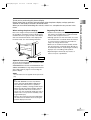
When moving the plasma display
Regarding This Manual
Due to the weight of this plasma display, two people should be used when moving it. Both people
should make sure to grasp the top of the display
with one hand and the base of the display with
the other hand, as in the following illustration.
• Product and company names appearing within
this manual are trademarks or registered trademarks of their respective owners.
• Although special care has been taken to ensure
that all information contained within this manual
is correct at time of writing, the information is
subject to change without notice.
• Make sure to read the manual carefully and follow all instructions contained within. We will not
be held responsible for any damages caused by
improper use or handling of this product.
IMPORTANT SAFETY INSTRUCTIONS
L0601(EN)v1.qx3
• Reproducing this manual by any means, in
whole or in part, is prohibited.
Figure 1
Optional Accessories
To mount the plasma display on a wall, the following accessory is available:
VISIONMOUNT™ Flat Panel TV Wall Mount from
SANUS SYSTEMS, for large flat panel televisions
(32” to 60”). Refer to page 21 for mounting the
plasma display.
NOTE:
The wall mounts are not supplied with the plasma display.
# CAUTION
• This PDP 6842PE is for use only with the
Sanus Systems Model VMPL. Wall Mount.
Use with other wall mounts is capable of
resulting in instability, causing possible injury.
• When mounting the plasma display with the
Sanus Systems wall mount, make sure to
mount it on the wood studs inside the wall, as
failure to do so may result in instability, causing possible injury.
• Refer to the instruction manual included with
the wall mount for details when securing the
plasma display to the wall.
3
L0601(EN)v1.qx3
04.8.10
3:08 PM
Page 4
CONTENTS
IMPORTANT SAFETY INSTRUCTIONS . . . . . . . . . . . . . . . . . . . . . . . . . . . . . . .2
SUPPLIED ACCESSORIES . . . . . . . . . . . . . . . . . . . . . . . . . . . . . . . . . . . . . . . .5
INSERTING THE REMOTE CONTROL BATTERIES . . . . . . . . . . . . . . . . . . . . . .5
REMOTE CONTROL RANGE . . . . . . . . . . . . . . . . . . . . . . . . . . . . . . . . . . . . . . .5
COMPONENT NAMES . . . . . . . . . . . . . . . . . . . . . . . . . . . . . . . . . . . . . . . . . . . .6
MAIN UNIT . . . . . . . . . . . . . . . . . . . . . . . . . . . . . . . . . . . . . . . . . . . . . . . . . . . . . . . . .6
REMOTE CONTROL . . . . . . . . . . . . . . . . . . . . . . . . . . . . . . . . . . . . . . . . . . . . . . . . . .7
OPERATING THE PLASMA DISPLAY . . . . . . . . . . . . . . . . . . . . . . . . . . . . . . . .8
BASIC OPERATIONS . . . . . . . . . . . . . . . . . . . . . . . . . . . . . . . . . . . . . . . . . . . . . . . . .8
SELECTING THE INPUT SIGNAL . . . . . . . . . . . . . . . . . . . . . . . . . . . . . . . . . . . . . . . .9
CHANGING THE ASPECT RATIO (SCREEN MODE) . . . . . . . . . . . . . . . . . . . . . . . . .10
STILL . . . . . . . . . . . . . . . . . . . . . . . . . . . . . . . . . . . . . . . . . . . . . . . . . . . . . . . . . . . . .11
SLEEP . . . . . . . . . . . . . . . . . . . . . . . . . . . . . . . . . . . . . . . . . . . . . . . . . . . . . . . . . . . .11
NAVIGATING THE SET UP MENU . . . . . . . . . . . . . . . . . . . . . . . . . . . . . . . . . . . . . . .12
Layout of the Setup Menu . . . . . . . . . . . . . . . . . . . . . . . . . . . . . . . . . . . . . . . . . . .12
ENTERING THE MAIN MENU . . . . . . . . . . . . . . . . . . . . . . . . . . . . . . . . . . . . . . . . . .13
PICTURE SELECT . . . . . . . . . . . . . . . . . . . . . . . . . . . . . . . . . . . . . . . . . . . . . . . . . .13
Automatically Adjusting the Picture Settings . . . . . . . . . . . . . . . . . . . . . . . . . . . . .14
Manually Adjusting the Picture Settings . . . . . . . . . . . . . . . . . . . . . . . . . . . . . . . .14
Initializing the Adjustments . . . . . . . . . . . . . . . . . . . . . . . . . . . . . . . . . . . . . . . . . .14
WINDOW SETTING . . . . . . . . . . . . . . . . . . . . . . . . . . . . . . . . . . . . . . . . . . . . . . . . . .15
SWITCHING THE DISPLAY LANGUAGE . . . . . . . . . . . . . . . . . . . . . . . . . . . . . . . . . .15
SETTING THE SCREEN SAVER AND THE BACKGROUND COLOR . . . . . . . . . . . . .16
Setting the Screen Saver . . . . . . . . . . . . . . . . . . . . . . . . . . . . . . . . . . . . . . . . . . .16
Setting the Background Color . . . . . . . . . . . . . . . . . . . . . . . . . . . . . . . . . . . . . . . .16
EXTERNAL INPUT TERMINALS . . . . . . . . . . . . . . . . . . . . . . . . . . . . . . . . . . . .17
CONNECTING DEVICES TO THE AV INPUT TERMINALS . . . . . . . . . . . . . . . . . . . .18
VIDEO Signal Connection (Basic Signal Transfer) . . . . . . . . . . . . . . . . . . . . . . . . .18
S-VIDEO Signal Connection (Better Signal Transfer) . . . . . . . . . . . . . . . . . . . . . . .18
CONNECTING DEVICES TO THE COMPONENT INPUT TERMINALS . . . . . . . . . . .19
Component 1 Signal (Y, Cb, Cr) Connection (Best Signal Transfer) . . . . . . . . . . . .19
Component 2 Signal (Y, Pb, Pr) Connection (Best Signal Transfer) . . . . . . . . . . . .19
CONNECTING PLASMA DISPLAY TO AUDIO SYSTEM . . . . . . . . . . . . . . . . . . . . . .20
AUDIO Signal Connection . . . . . . . . . . . . . . . . . . . . . . . . . . . . . . . . . . . . . . . . . . .20
CONNECTING THE POWER CABLE . . . . . . . . . . . . . . . . . . . . . . . . . . . . . . . .20
ATTACHING A WALL MOUNT BRACKET (SOLD SEPARATELY) . . . . . . . . . .21
MAINTENANCE . . . . . . . . . . . . . . . . . . . . . . . . . . . . . . . . . . . . . . . . . . . . . . . .22
CLEANING THE PLASMA DISPLAY . . . . . . . . . . . . . . . . . . . . . . . . . . . . . . . . . . . . .22
WARNING . . . . . . . . . . . . . . . . . . . . . . . . . . . . . . . . . . . . . . . . . . . . . . . . . . . .22
TROUBLESHOOTING GUIDE . . . . . . . . . . . . . . . . . . . . . . . . . . . . . . . . . . . . .23
SPECIFICATIONS . . . . . . . . . . . . . . . . . . . . . . . . . . . . . . . . . . . . . . . . . . . . . . .25
REFERENCIA RÁPIDA EN ESPAÑOL . . . . . . . . . . . . . . . . . . . . . . . . . . . . . . .26
INSTALACIÓN DE LAS PILAS EN EL CONTROL REMOTO . . . . . . . . . . . . . .26
NOMBRES DE LOS COMPONENTES . . . . . . . . . . . . . . . . . . . . . . . . . . . . . . .27
UNIDAD PRINCIPAL . . . . . . . . . . . . . . . . . . . . . . . . . . . . . . . . . . . . . . . . . . . . . . . . .27
CONTROL REMOTO . . . . . . . . . . . . . . . . . . . . . . . . . . . . . . . . . . . . . . . . . . . . . . . . .27
4
L0601(EN)v1.qx3
04.8.10
3:08 PM
Page 5
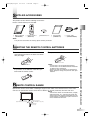
SUPPLIED ACCESSORIES
This product comes with the following accessories:
Please confirm that they are included.
POWER
VOL
MUTE
SCREEN MODE
STILL
INPUT SELECT
MENU
PREVIOUS
SLEEP
P Owner's Manual
(1EMN20088)
P Remote Control
(NE801UD)
P AA batteries x 2
P Set Up Guide
(1EMN20118)
P Power cable
(WBC0202H0001)
NOTE:
If any of these accessories are missing, please contact your dealer.
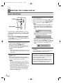
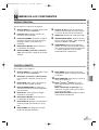
INSERTING THE REMOTE CONTROL BATTERIES
1
2
Remove the back cover of the remote control
while pressing the tab on the back cover down
with your finger.
Insert two AA size batteries, making sure that
the polarities of the batteries match the symbols inside the remote control.
3
Replace the back cover of the remote control.
NOTE:
• Do not insert a mix of old and new batteries.
• Do not insert a mix of different brands of batteries
or different types of batteries.
• Always use new, fresh batteries as replacement.
• Never attempt to charge, heat, burn or take apart
batteries.
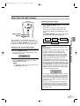
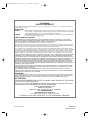
REMOTE CONTROL RANGE
Operate the remote control within a 30 degree angle on both sides of the infrared sensor on the main
unit. You can operate the remote control from a distance of several yards away from the main unit.
NOTE:
Other devices which use infrared beams, sunlight,
fluorescent lights, etc., may affect the range and
effectiveness of the remote control. Make sure the
plasma display is positioned in a place which minimizes interference from them.
STANDBY ON
VOLUME
POWER
INPUT SELECT
With in 30 degrees
With in 30 degrees
Approximately 5.5 yds (5 m)
Approximately 5.5 yds (5 m)
POWER
VOL
MUTE
SCREEN MODE
STILL
INPUT SELECT
DISPLAY
MENU
Approximately
7.6 yds (7 m)
CONTENTS / SUPPLIED ACCESSORIES / INSERTING THE REMOTE CONTROL BATTERIES / REMOTE CONTROL RANGE
DISPLAY
PREVIOUS
SLEEP
5
L0601(EN)v1.qx3
04.8.10
3:08 PM
Page 6
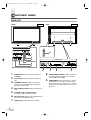
COMPONENT NAMES
MAIN UNIT
Figure 2
Front
STANDBY ON
VOLUME
Figure 3
Rear
POWER
INPUT SELECT
Input Terminals
STANDBY ON
POWER
R
AUDIO
L
VOLUME
8
INPUT SELECT
VIDEO2
1
2
3
S-VIDEO2
Input Terminals
Infrared Sensor
AUDIO
AC IN
AUDIO OUT
4
5
L
2
3
4
5
6
7
6
POWER button: Turns the power ON or in
STANDBY.
ON indicator: Lights up when the power is
ON.
STANDBY indicator: Lights up when the
power is in the standby mode. Disappears
when the power is ON.
INPUT SELECT button: Selects input terminals.
VOLUME K(up) / L(down) button:
Increases or decreases the volume.
AC IN terminal: Connect the supplied power
cable for a standard AC outlet.
AUDIO OUT: Output terminals for audio.
VIDEO1
7
8
9
S-VIDEO1
R
L
Y
Cb
Cr
R
L
Y
Pb
Pr
COMPONENT 1
L
COMPONENT 2
R
6
1
AUDIO
R
8
9
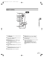
AUDIO/VIDEO/S-VIDEO: Input terminals for
an audio and video signal. You can select
either VIDEO or S-VIDEO.
COMPONENT: Input terminals for a component signal. You can make a Y-Cb-Cr interlaced connection to component 1 or Y-Pb-Pr
progressive or interlaced connection to component 2.
L0601(EN)v1.qx3
04.8.10
3:08 PM
Page 7
REMOTE CONTROL
Figure 4
1
POWER
VOL
2
3
4
MUTE
SCREEN MODE
STILL
INPUT SELECT
6
7
DISPLAY
9
MENU
PREVIOUS
SLEEP
10
11
8
1
2
3
4
5
6
7
8
POWER button: Turns the main power ON
or in STANDBY.
VOL K(up) / L(down) button: Increases or
decreases the volume.
MUTE button: Turns the audio off or on.
SCREEN MODE button: Selects aspect
ratios available for the screen.
STILL button: Pauses the image shown on
the screen.
9
COMPONENT NAMES
5
MENU button: Accesses the setup menu,
allowing you to access various settings.
10 PREVIOUS button: Moves up one level in
the setup menu.
11 K(up) / L(down) button: Selects the various
modes in the setup menu.
{(left) / B(right) button: Selects and
adjusts levels for the various settings.
B(enter) button: Also used as the enter
button.
INPUT SELECT button: Selects input terminals.
DISPLAY button: Displays the name of the
selected input terminal on the screen.
SLEEP button: Sets the sleep timer.
7
L0601(EN)v1.qx3
04.8.10
3:08 PM
Page 8
OPERATING THE PLASMA DISPLAY
BASIC OPERATIONS
3
POWER
VOL
POWER
MUTE
SCREEN MODE
NOTE:
STILL
• When you adjust the volume with the VOL K / L
button, a message such as the following is displayed on the screen. This message disappears
approximately 4 seconds after performing adjustments.
INPUT SELECT
INPUT SELECT
DISPLAY
The following is a simple explanation of the procedure for turning the power of the display ON or
in STANDBY, and the procedure for selecting the
input signal.
• If you turn the audio mute on, a message slowly
flashes on the screen. At this time, if you press
another button, this flashing stops.
The procedure described here is for the remote
control, however the POWER, INPUT SELECT
and VOLUME buttons on the plasma display can
also be used in the same way.
1
2
4
NOTE:
Press the POWER button to turn the power
STANDBY.
• It takes approximately 8 seconds for the screen to
display after turning the power ON, but this is not
a malfunction.
The ON indicator on the main unit disappears
and the STANDBY indicator lights up.
Select the input signal by pressing the INPUT
SELECT button.
Each time you switch the input, the name of
the selected input terminal is displayed on the
screen for approximately 4 seconds.
NOTE:
• "No signal" is displayed on the screen if there is
no input from the selected terminal and there is
no message currently displayed on the screen for
volume adjustment or the setup menu, etc.
• If there is no video signal and there has been no
operation from the remote control or the buttons
on the main unit for more than 15 minutes, the
auto shut-off function activates and the display
switches to standby mode.
8
• To turn the audio mute off, either press the MUTE
button again or press the VOL K / L button.
• If you press either the PREVIOUS, K, L, B or {
button in a mode apart from the image adjustment
mode. A message such as the following is displayed.
Press the POWER button.
Confirm that the STANDBY indicator is lit
before pressing the POWER button.
The power turns ON and the ON indicator on
the main unit lights up. The STANDBY indicator on the main unit disappears.
Adjust the volume and screen size according
to your requirements.
Perform adjustments to the volume (VOL K / L
button), screen aspect ratio (SCREEN MODE
button), and picture settings (MENU button)
NOTE:
• You cannot turn the power ON for approximately 3
seconds after the power enters the standby mode.
Do not turn the power STANDBY and then ON
again in a short time interval.
• Even if the power is turned STANDBY, the main
unit is in the standby mode. In order to shut the
main power of the display OFF, it is necessary to
remove the AC cord from the power outlet.
L0601(EN)v1.qx3
04.8.10
3:08 PM
Page 9
SELECTING THE INPUT SIGNAL
Selecting the Input Signal
POWER
VOL
1
SCREEN MODE
STILL
INPUT SELECT
INPUT SELECT
DISPLAY
DISPLAY
The procedure for selecting the input signal
described here is for use with the remote control.
However, the INPUT SELECT button on the plasma display can also be used in the same way.
Displaying the Current Input Signal
1
Press the DISPLAY button.
The name of the current input terminal is displayed on the screen.
2
To clear the name of the current input terminal,
press the DISPLAY button again or wait for
approximately 4 seconds.
NOTE:
• To redisplay the name of the input terminal, press
the DISPLAY button again.
Press the INPUT SELECT button to select the
input signal.
Each time you switch the input signal, the
name of the selected input terminal is displayed on the display for approximately 4 seconds.
The INPUT SELECT button cycles through the
input terminals in the following pattern:
Video 1
(S-Video 1)
Video 2
(S-Video 2)
Component 1
Component 2
NOTE:
• When switching the input signal, audio mute turns
ON temporarily.
• S-VIDEO1 takes preference over the VIDEO 1 jack,
as does S-VIDEO 2 over the VIDEO 2 jack.
Therefore, if there is input to the VIDEO and SVIDEO terminals at the same time, the S-VIDEO
signal is displayed on the screen. If the S-VIDEO
cable is not connected to the plasma display, the
VIDEO signal will be displayed on the screen.
• 480i (interlaced) signals can be connected to the
COMPONENT 1 and 2 terminals. Any of the following display formats: 480i, 480p (progressive), 1080i
and 720p (progressive) signals can be connected to
the COMPONENT 2 terminal. If one of these video
signals is detected, the format of the input signal is
displayed after the name of the current input terminal, as in the following manner.
OPERATING THE PLASMA DISPLAY
MUTE
• A "No signal" message appears if there is no video
signal and there is no message currently displayed
on the screen for volume adjustment or the setup
menu, etc. If there continues to be no video signal
for more than 10 seconds, "No signal" slowly moves
around the screen.
• If there is no video signal and there has been no
operation from the remote control or the buttons on
the main unit for more than 15 minutes, the auto
shut-off function activates and the display switches
to standby mode.
9
L0601(EN)v1.qx3
04.8.10
3:08 PM
Page 10
OPERATING THE PLASMA DISPLAY
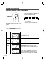
CHANGING THE ASPECT RATIO (SCREEN MODE)
Each time you change the screen mode, the
name of the selected mode is displayed on the
screen for approximately 4 seconds.
The SCREEN MODE button switches between
the screen modes in the following pattern.
POWER
VOL
MUTE
SCREEN MODE
SCREEN MODE
Normal
STILL
Full
Wide
Zoom
INPUT SELECT
NOTE:
DISPLAY
By changing the aspect ratio of the screen you
can select the manner in which you wish to view
the picture.
1
Press the SCREEN MODE button to display
the current screen mode.
2
Press the SCREEN MODE button a second
time to change the screen mode.
Mode
Picture
Normal
Normal
• When switching the input signal, the audio mute
turns ON temporarily.
• You can only select the "Normal" and "Zoom"
screen modes for 1080i and 720p video signals
connected to the COMPONENT 2 terminal.
Explanation
Normal will display a 4:3 picture at its standard 4:3
size. For 1080i and 720p video signals, a picture will
be displayed at 16:9 size.
Full
Full will display a 4:3 picture at a 16:9 size, with
horizontal elongation necessary to fill the screen.
Full
Wide
Wide
Zoom
Zoom
10
Wide will display a 4:3 picture at a 16:9 size, with less
horizontal elongation necessary to fill the screen
because a little bit of the top and bottom will be cut off.
Zoom will magnify the entire 4:3 picture to fill the
screen, with no horizontal elongation to fill the screen,
as more of the top and bottom are cut off. Use this
mode to view letterboxed 4:3 picture content to get a
widescreen picture. A 16:9 picture will be magnified
similarly, but to a lesser extent.
L0601(EN)v1.qx3
04.8.10
3:08 PM
Page 11
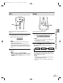
STILL
SLEEP
INPUT SELECT
POWER
VOL
DISPLAY
MUTE
SCREEN MODE
MENU
PREVIOUS
STILL
STILL
SLEEP
SLEEP
INPUT SELECT
DISPLAY
1
You can select the sleep timer.
1
Press the STILL button.
Press the SLEEP button.
The sleep timer is displayed on the screen.
The still mode turns on, and the image displayed on the screen is frozen.
NOTE:
• If the sleep timer is activated, the remaining time
is displayed on the screen.
If not activated, “0 minutes” is displayed.
NOTE:
• When the still mode is on, the message "Still"
slowly flashes on the screen.
• When the still mode is on, the audio is muted.
• You cannot turn the still mode on when there is no
video signal or when switching between video signals.
2
Press the SLEEP button to set the time.
The SLEEP button switches between the
times.
0 minutes
2
10 minutes
90 minutes
Press the STILL button again to turn the still
mode off.
NOTE:
• You can also press the INPUT SELECT,
DISPLAY, SLEEP, VOL K(up) / L(down), MUTE,
SCREEN MODE or MENU buttons to turn the still
mode off.
OPERATING THE PLASMA DISPLAY
You can freeze the image displayed on the
screen.
The timer starts counting down after the message displaying the set time disappears (after
approximately 4 seconds).
NOTE:
• The remaining time displayed for the sleep timer
changes in steps of 1 minute.
• To change the set time, repeat the above procedure.
11
L0601(EN)v1.qx3
04.8.10
3:31 PM
Page 12
OPERATING THE PLASMA DISPLAY
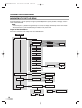
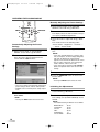
NAVIGATING THE SET UP MENU
In the setup menu, you can specify settings for picture adjustment, picture position, language, screen
saver and background.
NOTE:
• If you do not press any buttons for approximately 20 seconds, the display automatically exits the menu mode.
• We recommend to set to the initialized setting of “Manual” in the picture mode.
Layout of the Setup Menu
The various functions in the setup menu are outlined below:
MAIN MENU
Picture select
Picture mode
Dynamic
Manual
Movie
News
Brightness
Contrast
Color
Tint
Sharpness
Cool
Normal
Color temp.
Warm
Reset
Window setting
H-Position
Language
English
V-Position
Français
Español
Detail
Screen saver
Back ground
Fast
Opaque
Off
12
Slow
Translucent
L0601(EN)v1.qx3
04.8.10
3:08 PM
Page 13
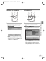
ENTERING THE MAIN MENU
PICTURE SELECT
INPUT SELECT
INPUT SELECT
DISPLAY
DISPLAY
K
MENU
PREVIOUS
MENU
MENU
PREVIOUS
MENU
SLEEP
PREVIOUS
B
SLEEP
1
Press the MENU button.
1
Enter the main menu with the MENU button.
“Picture select” is selected on the MAIN
MENU.
The display enters the main menu and the
MAIN MENU is displayed on the screen.
2
Press the B (ENTER) button.
The PICTURE SELECT menu is displayed on
the screen.
NOTE:
• If you press the PREVIOUS button or the MENU
button on the MAIN MENU, the menu is cancelled.
• For procedures which use the ENTER button, use
the B button as the ENTER button.
OPERATING THE PLASMA DISPLAY
L
NOTE:
• Press the PREVIOUS button to return to the MAIN
MENU. Pressing the MENU button cancels the
menu.
• Picture select display will disappear from the TV
screen automatically after about 20 seconds if you
do not press any buttons.
13
L0601(EN)v1.qx3
04.8.10
3:08 PM
Page 14
OPERATING THE PLASMA DISPLAY
INPUT SELECT
Manually Adjusting the Picture Settings
DISPLAY
1
K
MENU
PREVIOUS
MENU
PREVIOUS
B
{
2
SLEEP
3
2
Select the automatic adjustment mode according to the type of picture displayed on the
screen with the { / B buttons.
Select the mode to adjust with the K / L buttons.
The modes rotate in the following order:
"Picture mode" - "Brightness" - "Contrast" - ..
...- "Reset" - "Picture mode"
Automatically Adjusting the Picture
Settings
Select "Picture mode" on the PICTURE
SELECT screen with the K / L buttons.
Select "Manual" with the { / B buttons.
The display enters the manual mode, and you
can specify individual adjustments.
L
1
Select "Picture mode" on the PICTURE
SELECT screen with the K / L buttons.
4
Adjust the selected mode using the { / B buttons.
NOTE:
• If you have selected Brightness, Contrast, Color,
Tint, or Sharpness, the menu display disappears,
and a bar for adjusting the selected mode
appears in the center of the bottom of the screen.
• You can select "Color temp." from among three
modes: "Normal", "Warm" and "Cool".
• If you select "Reset" and press the B (ENTER)
button, the adjusted values return to their initial
settings.
5
To adjust a different mode, repeat steps 3 and 4.
6
Press the PREVIOUS button to return to the
Picture mode.
NOTE:
• Pressing the MENU button cancels the menu.
NOTE:
• There are 3 modes for automatically adjusting the
picture settings; "News", "Movie" and "Dynamic".
• MANUAL refers to manual picture settings adjustment.
3
Press the PREVIOUS button to return to the
MAIN MENU.
NOTE:
• Pressing the MENU button cancels the menu.
Initializing the Adjustments
1
2
Select "Reset" on the PICTURE SELECT
screen with the K / L buttons.
Press the B (ENTER) button.
The settings you specified individually are initialized.
NOTE:
• The initialized setting of "Manual" are as follows:
BRIGHTNESS:
50/100
CONTRAST:
70/100
COLOR:
50/100
TINT:
50/100
SHARPNESS:
1/2
COLOR TEMP.:
Normal
14
L0601(EN)v1.qx3
04.8.10
3:09 PM
Page 15
WINDOW SETTING
4
INPUT SELECT
Select "H-Position" to move the picture horizontally (left or right) and select "V-Position" to
move the screen vertically (up or down).
DISPLAY
K
MENU
5
PREVIOUS
MENU
{
Select the mode to adjust with the K / L button.
The { / B buttons are also used for moving
the picture vertically.
B
SLEEP
L
Adjust with the { / B buttons.
6
Press the PREVIOUS button to return to the
MAIN MENU.
NOTE:
You can move the picture displayed on the screen
up, down, left or right.
1
Enter the main menu with the MENU button.
2
Select "Window setting" on the MAIN MENU
screen with the K / L buttons.
SWITCHING THE DISPLAY LANGUAGE
INPUT SELECT
If there is no input from a video signal, "Window
setting" is grayed out and you cannot select it.
DISPLAY
K
MENU
PREVIOUS
MENU
{
PREVIOUS
B
SLEEP
L
OPERATING THE PLASMA DISPLAY
• Pressing the MENU button cancels the menu.
You can select the language displayed on the
screen from English, French and Spanish.
3
Press the B (ENTER) button.
The "WINDOW SETTING" menu is displayed
on the screen.
1
Enter the main menu with the MENU button.
2
Select "Language" on the MAIN MENU screen
with the K / L buttons.
3
Select the language with the { / B buttons.
4
Press the PREVIOUS button to return to the
MAIN MENU.
NOTE:
• Pressing the MENU button cancels the menu.
15
L0601(EN)v1.qx3
04.8.10
3:09 PM
Page 16
OPERATING THE PLASMA DISPLAY
SETTING THE SCREEN SAVER AND THE BACKGROUND COLOR
Setting the Screen Saver
INPUT SELECT
DISPLAY
1
Select "Screen saver" on the DETAIL screen
with the K / L buttons.
2
Select the mode with the { / B buttons.
K
MENU
PREVIOUS
MENU
{
PREVIOUS
B
NOTE:
SLEEP
• There are 3 modes for the screen saver; "Off",
"Slow", and "Fast".
"Slow" moves 1 pixel every 30 minutes and "Fast"
moves 1 pixel every 10 minutes. This prevents
images burning into the screen.
• When a 480i or 1080i input signal connected to
the COMPONENT 2 terminal is displayed, the vertical movement is different.
"Slow" moves 2 pixels every 60 minutes and
"Fast" moves 2 pixels every 20 minutes.
L
You can specify settings for the screen saver and
the background color.
1
Enter the main menu with the MENU button.
2
Select "Detail" on the MAIN MENU screen
with the K / L buttons.
3
Press the B (ENTER) button.
The "DETAIL" menu is displayed on the
screen.
3
Press the PREVIOUS button to return to the
MAIN MENU screen.
NOTE:
• Pressing the MENU button cancels the menu.
Setting the Background Color
1
Select "Background" on the DETAIL screen
with the K / L buttons.
2
Select the mode with the { / B buttons.
Select "Opaque" or "Translucent" for the background color.
3
Press the PREVIOUS button to return to the
MAIN MENU screen.
NOTE:
• Pressing the MENU button cancels the menu.
NOTE:
• Press the PREVIOUS button to return to the
MAIN MENU. Pressing the MENU button cancels
the menu.
16
L0601(EN)v1.qx3
04.8.10
3:09 PM
Page 17
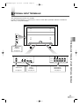
EXTERNAL INPUT TERMINALS
The following input terminals are available.
In order to view television, it is necessary to connect a tuner device (example: cable box, satellite box,
DTV, etc.) to the plasma display.
R
AUDIO
L
S-VIDEO2
AV Input Terminals
VIDEO 2
S-VIDEO 2
See page 18.
AUDIO
AUDIO OUT
L
AUDIO
R
VIDEO1
S-VIDEO1
R
L
Y
Cb
Cr
R
L
Y
Pb
Pr
COMPONENT 1
L
COMPONENT 2
R
Audio Output Terminals
AUDIO OUT
AV Input Terminals
VIDEO 1
S-VIDEO 1
Component Input Terminals
COMPONENT 1
COMPONENT 2
See page 20.
See page 18.
See page 19.
OPERATING THE PLASMA DISPLAY / EXTERNAL INPUT TERMINALS
VIDEO2
17
L0601(EN)v1.qx3
04.8.10
3:09 PM
Page 18
EXTERNAL INPUT TERMINALS
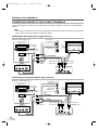
CONNECTING DEVICES TO THE AV INPUT TERMINALS
Connect the output of the device to the input terminals of plasma display as shown in the following illustrations.
NOTE:
• You will select TV channels with the VCRs or Cable/Satellite set top box that will be viewed on the plasma display.
• Cables shown here are not included with the plasma display.
VIDEO Signal Connection (Basic Signal Transfer)
Example of input signal source
Audio input to
L/R sockets
(DVD Player)
R
AUDIO
Antenna or
cable signal
(VCR)
(Cable/Sat STB)
Antenna, cable,
satellite signal
3×RCA audio
video cables
Audio
OUT
L
Video
OUT
Video input to
RCA socket
VIDEO2
S-VIDEO2
AUDIO-VIDEO
(Camcorder)
R
L
Audio input to
L/R sockets
Video input to
RCA socket
S Video
OUT
AUDIO
R
VIDEO1
S-VIDEO1
L
S-VIDEO Signal Connection (Better Signal Transfer)
Example of input signal source
Audio input to
L/R sockets
(DVD Player)
R
AUDIO
Antenna or
cable signal
(VCR)
(Cable/Sat STB)
Antenna, cable,
satellite signal
L
Video input to
S-VIDEO socket
VIDEO2
S-VIDEO2
S-VIDEO
(Camcorder)
AUDIO
2×RCA
audio cables
R
Audio
OUT
L
Video
OUT
Audio input to
L/R sockets
Video input to
S-VIDEO socket
S Video
OUT
AUDIO
R
18
VIDEO1
L
S-VIDEO1
L0601(EN)v1.qx3
04.8.10
3:09 PM
Page 19
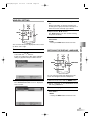
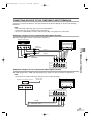
CONNECTING DEVICES TO THE COMPONENT INPUT TERMINALS
Connect the output of the device to the input terminals of the plasma display as shown in the following
illustrations.
NOTE:
• When connecting a 480i input signal, connect it to COMPONENT 1.
• Cables shown here are not included with the plasma display.
• You can use COMPONENT 2 for 480i, 1080i (interlaced), 480p, 720p (progressive) video signals.
Component 1 Signal (Y, Cb, Cr) Connection (Best Signal Transfer)
480i (interlaced) signals can be connected to Component 1.
(Example: DVD Player)
R
L
Y
CB
CR
3×RCA
video cables
AUDIO
2×RCA
audio cables
AUDIO
R
L
Y
Cb
Cr
R
L
Y
Pb
Pr
COMPONENT 1
COMPONENT 2
Component 2 Signal (Y, Pb, Pr) Connection (Best Signal Transfer)
480i, 480p (progressive), 1080i and 720p (progressive) signals can be connected to Component 2.
EXTERNAL INPUT TERMINALS
Y, Cb, Cr
NOTE:
You will select TV channels with the box that will be seen on the plasma display.
(Example: Set Top Box for DTV)
R
L
Y
PB
Antenna, cable,
satellite signal
PR
AUDIO
R
L
Y
Cb
Cr
R
L
Y
Pb
Pr
COMPONENT 1
COMPONENT 2
AUDIO
2×RCA audio cables
Y
Pb Pr
19
L0601(EN)v1.qx3
04.8.10
3:09 PM
Page 20
EXTERNAL INPUT TERMINALS
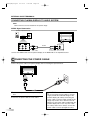
CONNECTING PLASMA DISPLAY TO AUDIO SYSTEM
NOTE:
Cables shown here are not included with the plasma display.
AUDIO Signal Connection
(Example: Amplifier/Receiver)
AUDIO IN
VIDEO
TV
AUX
AUDIO OUT
L
AUDIO
L
R
R
2×RCA
audio cables
Audio output
to L/R sockets
Connect the AUDIO OUT from the plasma display to the AUDIO IN on the amplifier/receiver.
CONNECTING THE POWER CABLE
Connect the power cable to the plasma display after connecting the input terminals.
AC IN
2
1
1
2
20
Connect the power cable to the plasma display
first.
Connect the power cable to an AC outlet.
# CAUTION
• Do not connect the power cable to a power
supply outside the indicated voltage of the
plasma display (AC 120V). Connecting the
power cable to a power supply outside of this
range may result in fire or electrical shocks.
• Always use the power cable included with the
plasma display. Do not use any other cable.
For safety, make sure to always connect the
power cable to a three pronged AC outlet.
L0601(EN)v1.qx3
04.8.10
3:09 PM
Page 21
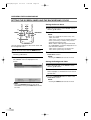
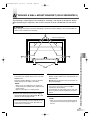
ATTACHING A WALL MOUNT BRACKET (SOLD SEPARATELY)
The following is a description of the method for attaching a wall mount to the plasma display.
When performing this operation, refer to the instruction manual included with the wall mount
kit.
# CAUTION
• Any damage caused by incorrectly attempting to mount the plasma display is not covered under the
terms of the manufacturers warranty.
2
Plasma Display rear
Stand
1
Turn the plasma display over and place it
screen-first onto a table which has a soft cloth
draped over it.
3
Place the plasma display in a way so that the
stands hang over the edge of the table.
NOTE:
• Make sure to use a table which can support the
weight of the plasma display and is larger than the
plasma display.
• Make sure the table is in a stable location.
2
Remove the stands from the plasma display.
Unscrew the M5 screws indicated by 1 , and
remove the left and right stands.
NOTE:
• The screws and stands you have removed are necessary for reattachment at a later date. Make sure
to keep them in a safe place.
Attach the left and right TV rails to the plasma
display using the M8 screws included with the
wall mount kit.
2 indicates the position of the screw holes on
the plasma display
NOTE:
• Only use the screw holes indicated by 2 for
mounting the plasma display.
• For instructions on how to attach the TV rails, refer
to the instruction manual included with the mount
wall kit.
4
Attach the plasma display to the wall.
NOTE:
• Refer to the instruction manual included with the
wall mount when securing the plasma display to
the wall.
EXTERNAL INPUT TERMINALS / CONNECTING THE POWER CABLE / ATTACHING A WALL MOUNT BRACKET (SOLD SEPARATELY)
1
1
21
L0601(EN)v1.qx3
04.8.10
3:09 PM
Page 22
MAINTENANCE
CLEANING THE PLASMA DISPLAY
Always unplug the plasma display from the AC
outlet before cleaning.
NOTE:
Clean the case of the plasma display with a soft
cloth which has been wet and wrung dry.
If the screen of the plasma display is dirty or
dusty, wipe it clean with a soft cloth.
Never use a solvent, alcohol or any other abrasive liquid to clean the plasma display.
Always make sure the area around vents on the plasma display is clear and clean. Failure to do this may
result in fire or cause the plasma display to fail prematurely.
WARNING
Preventing Image Burn on the plasma display
Fixed images displayed on the plasma display for an extended period of several hours may cause
uneven pixel aging causing damage to the plasma display. The screensaver mode helps reduce this
phenomenon, but in general you should to try avoid displaying fixed images for extended periods on
the plasma display.
Images of high luminance displayed on the plasma display for more than 60 seconds may cause lingering images to remain on the screen. These images will automatically disappear, but may take
time depending on the luminance of the images and how long they were displayed on the screen.
22
L0601(EN)v1.qx3
04.8.10
3:09 PM
Page 23
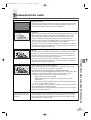
TROUBLESHOOTING GUIDE
•IGNITION NOISE:
Black spots or horizontal streaks may appear, picture may flutter or drift.
Usually caused by interference from automobile ignition systems, neon
lamps, electrical drills and other electrical appliances.
•GHOSTS:
Ghosts are caused by the television signal following two paths. One is the
direct path and the other is reflected from tall buildings, hills or some
other objects. Changing the direction or position of the antenna may
improve reception. Ghosting may also be caused by defects in the
antenna system such as unshielded leads or connecting several sets to
the same antenna without using multiple antenna couplers.
Ghosting occurring when the plasma display is connected to a cable TV
system may indicate a bad cable wire or loose connection. Confirm that
the cable wire is properly connected.
•RADIO FREQUENCY INTERFERENCE:
The interference produces moving ripples or diagonal streaks, and in
some cases, causes loss of contrast in the picture.
•PREVENTION OF AN OBSTACLE TO RADIO RECEIVERS
This monitor has been designed pursuant to the FCC class B Rules. This
is to prevent a problem to Radio receivers. lf this monitor causes a
problem to Radio receivers, then take the following steps:
- Keep the monitor away from Radio.
- Adjust Radio antennas in order for the monitor not to receive
interference.
- The antenna cable of Radio should be kept away from the monitor.
- Use a coaxial cable for antenna.
You can check if this monitor influences Radio receivers by turning off all
other equipment other than the monitor.
If you find a problem receiving Radio when using the monitor, check the
instructions mentioned above.
Vertical stripes appear,
depending on the screen
contents.
•The plasma display panel is lighting the phosphors by the discharge of
internal radiation. Depending on the screen contents, in rare cases this
may cause vertical stripes to appear because of failure to light. Please
note that this is not a malfunction.
MAINTENANCE / WARNING / TROUBLESHOOTING GUIDE
•SNOW:
If your receiver is located in the fringe area of a television station where
the signal is weak, your picture may be marred by the appearance of
small dots. When the signal is extremely weak, it may be necessary to
install a special antenna to improve the picture.
Snowing occurring when the plasma display is connected to a cable TV
system may indicate a bad cable wire or loose connection. Confirm that
the cable wire is properly connected.
23
L0601(EN)v1.qx3
04.8.10
3:09 PM
Page 24
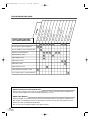
CHECK THESE ITEMS AND
TRY THESE CORRECTIONS
Remo
SYM
PTO
M
te co
ntrol
does
No pic
not w
ork
ture,
no so
u
n
d
Soun
d OK
, pictu
re po
Pictu
or
re OK
, sou
nd po
Pictu
or
re blu
rred
Weak
Pictu
re
Lines
or str
eaks
in pic
Pictu
ture
re roll
s ver
tically
No co
lor
Poor
pictur
e
Irregu
lar do
ts on
the s
creen
TROUBLESHOOTING GUIDE
Be sure external connections are correct.
Be sure power cable is plugged in.
Be sure PANEL is power switched "ON"
Check for local interference
Adjust Contrast control
Adjust Bright control
Adjust Color control
Adjust Tint control
Adjust Volume control
Check batteries in Remote control
It is a characteristic of a Plasma Display.
About Interference to Infrared Devices
Please note in advance that using other infrared devices (such as infrared cordless headphones)
near the plasma display may cause infrared interference to occur.
About Pixel Defects
A plasma display is created by using a collection of miniature pixels. It is possible to display more
than 99.99% of valid pixels, however a small fraction of pixels over the life of the product may not
illuminate or may constantly be illuminated.
This is not to be considered a defect in the plasma panel.
24
L0601(EN)v1.qx3
04.8.10
3:09 PM
Page 25
SPECIFICATIONS
Display Features
Type
Screen Size
Pixel Resolution
Output Colors
Screen Aspect Ratio
Viewing Angle
Contrast Ratio
Brightness
Comb Filter Type
Available Input Format
Plasma panel
42 in. Wide VGA panel
852 (H) x 480 (V)
16.7 million
16:9
160 degrees
1000:1
470 cd/m2 (PEAK)
3-Dimensional Y/C Separation
720p/1080i/480p/480i (720p/1080i/480p: Component 2 only)
Audio Features
Sound Output
Speaker
5W + 5W, 10% THD
2.8 in x 1.6 in Oval Type x 2
Additional Features
Screen Saver
Trilingual OSD
Color Temperature Select
AV Memory
Widescreen Modes
Sleep Timer
Wall Mount Kit Ready
Off/Slow/Fast
English/Spanish/French
Cool/Normal/Warm
Dynamic/Manual/News/Movie
4:3 Standard, Full, Wide, Zoom
90 minutes
For VMPLs, SANUS SYSTEMS
Component AV Input (1)
Component AV Input (2)
Composite AV Input (1)
S-Video (1)
Composite AV Input (2)
S-Video (2)
Analog Audio output
SD component video/Y, Cb, Cr (RCA x 3) - rear
audio L/R (RCA x 2) - rear
HD component video/Y, Pb, Pr (RCA x 3) - rear
audio L/R (RCA x 2) - rear
Composite video ( RCA x 1 ) - rear
S-Video (4 pin DIN ) - rear
audio L/R (RCA x 2) - rear
Composite video ( RCA x 1 ) - side
S-Video (4 pin DIN ) - side
audio L/R (RCA x 2) - side
audio L/R (RCA x 2) - rear
General
Power In
Power Consumption
Exterior Color
Dimension (Incl. stand) (Width x Height x Depth)
Weight
120V ±10%, 60Hz/AC
350 W (Standby: 0.8W)
Silver & Black
41 1/2 x 28 3/4 x 13 in. (1054 x 730 x 330 mm)
94.8 lbs (43 kg)
NOTE:
The specifications and design of this product are subject to change without notice.
As an ENERGY STAR ® Partner, our company has determined that this product meets
the ENERGY STAR ® guidelines for energy efficiency. ENERGY STAR ® is a U.S. registered mark.
TROUBLESHOOTING GUIDE / SPECIFICATIONS
Connectors
25
L0601(EN)v1.qx3
04.8.10
3:09 PM
Page 26
REFERENCIA RÁPIDA EN ESPAÑOL
Traslado de la unidad principal
Debido al considerable peso de la pantalla de plasma, se necesitan dos personas para trasladarla.
Ambas personas deben sujetar or sostener la parte superior de la pantalla con una mano y la base de la
pantalla con la otra mano.
Vea la Figura 1 en la página 3.
INSTALACIÓN DE LAS PILAS EN EL CONTROL REMOTO
26
1
Para retirar la tapa trasera del control remoto,
presione la lengüeta hacia abajo con un dedo.
2
Instale dos pilas tamaño AA, asegurándose de
que la polaridad de las pilas coincida con los
símbolos impresos en el interior del control
remoto.
3
Instale la tapa trasera en el control remoto.
L0601(EN)v1.qx3
04.8.10
3:09 PM
Page 27
UNIDAD PRINCIPAL
Vea las Figura 2 y Figura 3 en la página 6.
1
2
3
4
5
Botón POWER: Para encender (ON) o dejar
en modo de espera (STANDBY).
Indicador ON: Se ilumina cuando la alimentación está encendida.
Indicador STANDBY: Se ilumina cuando la
pantalla se encuentra en modo de espera.
Se apaga cuando se enciende la alimentación.
6
7
8
9
Botón INPUT SELECT: Para seleccionar
los terminales de entrada.
Botón VOLUME K(aumento) / L(disminución): Para aumentar o disminuir el nivel de
volumen.
Terminal AC IN: Conecte el cable de alimentación suministrado entre este terminal
y una toma de corriente de CA estándar.
AUDIO OUT: Terminal de salida para audio.
AUDIO/VIDEO/S-VIDEO: Terminal de entrada para señales de audio y video. Se puede
seleccionar VIDEO o S-VIDEO.
COMPONENT: Terminal de entrada para
señales de componente. Es posible realizar
una conexión entrelazada para componente
1 o Y-Pb-Pr progresivo o una conexión
entrelazada para componente 2.
CONTROL REMOTO
Vea la Figura 4 en la página 7.
1
2
3
4
5
6
7
8
Botón POWER: Para encender (ON) o dejar
en modo de espera (STANDBY).
Botón VOL K(aumento) / L(disminución):
Para aumentar o disminuir el nivel de volumen.
Botón MUTE: Para activar o desactivar la
función de silenciamiento de audio.
Botón SCREEN MODE: Se utiliza para
seleccionar uno de los formatos disponibles
para la pantalla.
Botón STILL: Para congelar la imagen
mostrada en la pantalla.
9
Botón MENU: Para acceder al menú de
configuración, donde se pueden hacer diversos ajustes.
REFERENCIA RÁPIDA EN ESPAÑOL / IINSTALACIÓN DE LAS PILAS EN EL CONTROL REMOTO / NOMBRES DE LOS COMPONENTES
NOMBRES DE LOS COMPONENTES
10 Botón PREVIOUS: Para subir un nivel en el
menú de configuración.
11 Botón K(arriba) / L(abajo): Para seleccionar diversos modos en el menú de configuración.
Botón {(izquierda) / B(derecha): Para
seleccionar y ajustar niveles para las diversas opciones de ajuste.
Botón B(introducción): También se utiliza
como botón de introducción.
Botón INPUT SELECT: Para seleccionar
los terminales de entrada.
Botón DISPLAY: Muestra el nombre del terminal de entrada seleccionado en la pantalla.
Botón SLEEP: Para programar el temporizador de apagado automático.
27
L0601(EN)v1.qx3
04.8.10
3:09 PM
Page 28
SYLVANIA
LIMITED WARRANTY
FUNAI CORP. will repair this SYLVANIA product, free of charge in the USA in the event of defect in materials or
workmanship as follows:
DURATION:
PARTS:
LABOR:
FUNAI CORP. will provide parts to replace defective parts without charge for one (1) year
from the date of original retail purchase. Three (3) years for Plasma Panel. Certain parts
and Plasma image burn-in are not covered under this warranty.
FUNAI CORP. will provide the labor without charge for a period of ninety (90) days from
the date of original retail purchase.
LIMITS AND EXCLUSIONS:
THIS WARRANTY IS EXTENDED ONLY TO THE ORIGINAL RETAIL PURCHASER. A PURCHASE
RECEIPT OR OTHER PROOF OF ORIGINAL RETAIL PURCHASE WILL BE REQUIRED TOGETHER
WITH THE PRODUCT TO OBTAIN SERVICE UNDER THIS WARRANTY.
This warranty shall not be extended to any other person or transferee.
This warranty is void and of no effect if any serial numbers on the product are altered, replaced, defaced,
missing or if service was attempted by an unauthorized service center. This SYLVANIA Limited warranty
does not apply to any the product not purchased and used in the United States.
This warranty only covers failures due to defects in material or workmanship which occurs during normal
use. It does not cover damage which occurs in shipment, or failures which are caused by repairs, alterations
or product not supplied by FUNAI CORP., or damage which results from accident, misuse, abuse, mishandling, misapplication, alteration, faulty installation, improper maintenance, commercial use such as hotel,
rental or office use of this product or damage which results from fire, flood, lightning or other acts of God.
THIS WARRANTY DOES NOT COVER PACKING MATERIALS, ANY ACCESSORIES (EXCEPT REMOTE
CONTROL), ANY COSMETIC PARTS, COMPLETE ASSEMBLY PARTS, DEMO OR FLOOR MODELS.
FUNAI CORP. AND ITS REPRESENTATIVES OR AGENTS SHALL IN NO EVENT BE LIABLE FOR ANY
GENERAL, INDIRECT OR CONSEQUENTIAL DAMAGES ARISING OUT OF OR OCCASIONED BY THE
USE OF OR THE INABILITY TO USE THIS PRODUCT. THIS WARRANTY IS MADE IN LIEU OF ALL
OTHER WARRANTIES, EXPRESS OR IMPLIED, AND OF ALL OTHER LIABILITIES ON THE PART OF
FUNAI, ALL OTHER WARRANTIES INCLUDING THE WARRANTY OF MERCHANTABILITY AND FITNESS FOR A PARTICULAR PURPOSE, ARE HEREBY DISCLAIMED BY FUNAI AND ITS REPRESENTATIVES IN THE UNITED STATES.
ALL WARRANTY INSPECTIONS AND REPAIRS MUST BE PERFORMED BY A FUNAI AUTHORIZED
SERVICE CENTER. THIS WARRANTY IS ONLY VALID WHEN THE UNIT IS CARRIED-IN TO A FUNAI
AUTHORIZED SERVICE FACILITY.
THE PRODUCT MUST BE ACCOMPANIED BY A COPY OF THE ORIGINAL RETAIL PURCHASE
RECEIPT. IF NO PROOF OF PURCHASE IS ATTACHED, THE WARRANTY WILL NOT BE HONORED
AND REPAIRS COSTS WILL BE CHARGED.
IMPORTANT:
THIS LIMITED WARRANTY GIVES YOU SPECIFIC LEGAL RIGHTS. YOU MAY HAVE OTHER RIGHTS THAT
VARY FROM STATE TO STATE. IF, AT ANY TIME DURING THE WARRANTY PERIOD, YOU ARE UNABLE TO
OBTAIN SATISFACTION WITH THE REPAIR OF THIS PRODUCT, PLEASE CONTACT FUNAI CORP.
ATTENTION:
FUNAI CORP. RESERVES THE RIGHT TO MODIFY ANY DESIGN OF THIS PRODUCT WITHOUT PRIOR NOTICE.
To locate your nearest SYLVANIA Authorized Service Center or general service procedure, please call 1-800-605-8453 or write to the following:
FUNAI CORPORATION, INC.
SERVICE CENTER
19900 Van Ness Avenue, Torrance, CA 90501
Tel :1-800-605-8453
http://www.funai-corp.com
Head Office: 100 North Street, Teterboro, NJ 07608
PLEASE DO NOT SHIP YOUR UNIT TO THE TETERBORO ADDRESS.
Printed in Malaysia
1EMN20088
L0601UB★★★★★