1
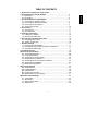
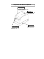
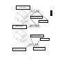
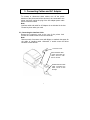
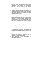
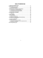
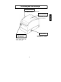
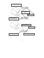
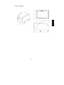
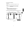
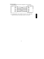
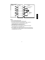
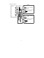
X0KA02001-Y911-02
THERMAL PRINTER
FP-410
USER’S MANUAL
Federal Communications Commission
Radio Frequency Interference Statement
For United States Users
This equipment has been tested and found to comply with the limits for a Class A digital
device, pursuant to Part 15 of the FCC Rules. These limits are designed to provide
reasonable protection against harmful interference when the equipment is operated in a
commercial environment. This equipment generates, uses and can radio frequency energy
and, if not installed and used in accordance with the instruction manual, may cause
harmful interference to radio communications. Operation of this equipment in a residential
area is likely to cause harmful interference in which case the user will be required to
correct the interference at his own expense
Exigences
This Class A digital apparatus meets all requirements of the Canadian
Interference-Causing Equipment Regulations.
Cet appareil numérique de la classe A respecte toutes les exigenves du Règlement sur le
matériel brouileur du Canada.
Notice to German Users
Gemäß der Dritten Verordnung zum Gerätesicherheitsgesetz
(Maschinenlärminformations-Verordnung-3.GSGV) ist der
Geräusch-Emissionswert Kleiner als 70 dB (A)
arbeitsplatzbezogene
CE
Manufacturer’s Declaration of Conformity
According to Electromagnetic Compatibility Directive 89/336/EEC and Low
Voltage Directive 73/23EEC, AnnexIIIB.
Declares, in sole responsibility, that the following products, including the options or accessories
Product Type : FP-410
Model Number : KA02001-D0XX,D1XX,D2XX
Approval ID Number: S 50012911
Referred to in this declaration, conforms with the following directives and standards;
Electromagnetic Compatibility Directive 89/336/EEC, 92/31/EEC, 93/68/EEC
Low Voltage Directive 73/23/EEC, 93/68/EEC
EN55022:1998, Class A
EN55024:1998
EN61000-3-2:1995, EN61000-3-2:1995,Amendment1:1998,
EN61000-3-2:1995,Amendment2:1998, EN6100-3-3:1995
Warning
This is a Class A product of Electromagnetic Interference(EMI) standard.
In a domestic environment this product may cause radio interference in which case the
user may by required to take adequate measures.
Notice
The contents of this manual may be revised without prior notice.
No part of this manual may be reproduced in any form without permission.
Copyright © 2002 FUJITSU ISOTEC LIMITED.
1
1. Appearance and Names of Components ...............................................
2. Consumable Parts and AC Adapter ........................................................ 5
2-1. Roll Paper ........................................................................................... 5
2-2. AC adapter .......................................................................................... 6
3. Connecting Cables and AC Adapter ....................................................... 7
3-1. Connecting the Interface Cable ........................................................... 7
3-2. Connecting the Drawer Kick Cable...................................................... 8
3-3. Connecting the AC Adapter................................................................. 9
3-4. Turning on the Power .......................................................................... 10
4. Control Panel ............................................................................................ 11
4-1. Control Panel....................................................................................... 11
4-2. Error Indication .................................................................................... 11
5. Loading the Roll Paper............................................................................. 12
5-1. Loading the roll paper.......................................................................... 12
5-2. Removing the Paper Roll .................................................................... 15
6. Preventing and Clearing Paper Jams...................................................... 16
6-1. Preventing Paper Jams ....................................................................... 16
6-2. Clearing a Paper Jam.......................................................................... 16
7. Periodic Cleaning ..................................................................................... 17
7-1. Cleaning the Thermal Head................................................................. 17
7-2. Cleaning the Paper Holder and Paper Feed Section........................... 17
7-3. Cleaning the Platen Roller................................................................... 17
8. Conditions for Use.................................................................................... 18
Appendix A: Specifications ......................................................................... 38
A-1. General Specifications ........................................................................ 38
A-2. Cutter Specifications ........................................................................... 40
A-3. Specifications of Paper Supply ........................................................... 40
A-4. Specifications of Interfaces ................................................................. 40
A-5. Specifications of Environmental Conditions ........................................ 40
A-6. Specifications of Reliability.................................................................. 41
A-7. Black mark specification ..................................................................... 41
Appendix B: Interface................................................................................... 43
B-1. Serial Interface.................................................................................... 43
B-2. Parallel Interface ................................................................................. 46
B-3. USB Interface...................................................................................... 48
B-4. Drawer Kick Connector ....................................................................... 48
B-5. Specifications of Power Supply........................................................... 51
Appendix C: Special Modes......................................................................... 52
C-1. Test Printing........................................................................................ 52
C-2. HEX Dump.......................................................................................... 53
C-3. Setting up the Printer .......................................................................... 54
C-4. Setup Items......................................................................................... 56
2
ENGLISH
TABLE OF CONTENTS
1. Appearance and Names of Components
Control panel
This panel contains status lamps
and operating switches.
Top cover
Open and close this
cover to replace forms.
Power switch
Cover open lever
This switch turns the
printer power on and off.
Pushing this lever down
opens the top cover.
3
ENGLISH
Interface connector
(Serial interface)
Drawer kick connector
Power connector
Interface connector
(Parallel interface)
Interface Connector
(USB Interface Type-B)
Power connector
Drawer kick connector
Interface Connector
(USB Interface Type-A)
4
2. Consumable Parts and AC Adapter
Use the Thermal paper specified below. Using an AC adapter other
than the specified model might cause a malfunction, fire, or electrical
shock.
2-1. Roll Paper specification (Thermal paper)
(1)Paper width: 80
0
-1.0
mm
(2)Outer roll diameter: 75~90µm φ102mm or less
90~150µm φ90mm or less
(3)Thickness : 75~150µm
(4)Core outer/inner diameter
Paper Thickness
Core outer
Core inner
75~90µm
φ18±0.5mm
φ12±0.5mm
90~150µm
φ32±0.5mm
φ25.4±0.5mm
(5)Printed surface: Outer edge of roll
(6)Terminating: Do not use paste or glue to secure the roll paper or its
core.
: Do not fold the tail end of the paper.
(7)Recommended paper
Oji Paper Co., Ltd.
PD190R(middle image stability paper), 75µm(thickness)
PD160R(high image stability paper), 75µm(thickness)
Mitsubishi Paper Mills Limited
PB670 (Red/black normal type paper), 75µm(thickness)
PB770 (blue/black normal type paper), 75µm(thickness)
P220AE-1 (normal type paper, card ticket), 150µm(thickness)
Nippon Paper lndustries
HD75 (normal type paper, label), 150µm(thickness)
5
Do not use a paper roll with frayed ends (rough paper edges).
Otherwise, a printer error might occur.
Depending on the type and thickness of the paper, it may be necessary
to change the setting for print density.
2-2. AC adapter (option)
Model name : CA02485-0020
Input : 100 to 240V AC, 50/60Hz
Output : DC24V±5%, 1.5A
6
ENGLISH
Note:
3. Connecting Cables and AC Adapter
To connect or disconnect these cables, turn off the power
switches of the printer and all the devices to be connected to the
printer, and then unplug the plug of the AC adapter power cable
from the electrical outlet.
Note:
Interface cable and cable for AC Adapter is not included in the box.
Please buy them when you need.
3-1. Connecting the Interface Cable
Remove the connector cover at the rear of the printer. And
connect the interface cable to the rear connector.
Note:
Remove notch of connector cover with Nipper, to maintain the space for
the cable of interface cable. Otherwise, it would cause the failure
because of cable broken.
Connector cover
Serial interface cable
* After connecting the
cable, secure it with
the two screws.
Parallel interface cable
*After connecting the
cable, secure it with
the clips.
7
USB Interface Cable
Type-A
USB Interface Cable
Type-B
3-2. Connecting the Drawer Kick Cable
Remove the connector cover at the rear of the printer. And connect
the drawer kick cable to the rear connector.
Note:
Remove notch of connector cover with Nipper, to maintain the
space for the cable of drawer kick cable. Otherwise, it would cause
the failure because of cable broken.
Connector cover
Drawer kick cable
8
ENGLISH
Connector Cover
3-3. Connecting the AC Adapter
Note:
To connect or disconnect the AC adapter, turn off the power
switches of the printer and all the devices to be connected to the
printer. Then, unplug the plug of the AC adapter power cable from
the electrical outlet.
(1)Connect the AC adapter to the AC adapter power cable.
Note:
Use only the specified AC adapter and specified AC adapter power
cable.
(2)Connect the cable connector of the AC adapter to the printer
connector.
Note:
Remove notch of connector cover with Nipper, to maintain the
space for the cable of AC adopter. Otherwise, it would cause the
failure because of cable broken.
(3) Connect the plug of the power cable to electrical outlet.
Connector cover
Cable connector of AC
adapter
Note:
To disconnect the cable connector of the AC adapter from the printer
connector, hold and pull the cable connector. The connector can be
easily unlocked and pulled out. Do not disconnect the connector by
pulling on the cable. Otherwise, the connector might be damaged.
9
Power switch
10
ENGLISH
3-4. Turning on the Power
After the AC adapter is connected as explained in Section 3-3,
"Connecting the AC Adapter," turn on the power switch at the side of the
printer. The POWER lamp on the control panel lights.
4. Control Panel
4-1.
Control Panel
POWER LED lamp
Lights when the power switch is turned
on and power is supplied to the printer.
ERROR LED lamp
Lights or blinks to indicate errors.
FEED switch
Pressing this switch once advances the
paper one line. Holding down this switch
advances paper continuously.
4-2. Error Indication
The ERROR LED lamp lights or blinks when the printer is in the following
states.
Error status
ERROR LED
No paper (paper end)
On
Top cover open
Printing stopped due to overheating of
thermal head
Power supply error
Paper near end
Blinking
The POWER LED lamp blinks when the printer is in the following
states.
Error status
POWER LED
Print head cable loose or disconnected
Blinking
Temperature too low
Power supply error
11
5-1. Loading the roll paper
(1)Push the cover open lever down, and open the top cover.
Note:
Thermal Head may be broken when Static Electricity impressed.
Do not touch Thermal Head.
(2) Peel off the pasted end of a new roll of paper.
Note:
Because the printer cannot print on the pasted portion, remove it
completely.
(3) Place the roll as shown below, and pull the leading edge of the
paper forward.
Paper roll section
Thermal head
12
ENGLISH
5. Loading the Roll Paper
Notes:
1. Do not use paper rolls that are deformed as shown below.
Otherwise, a printer error, paper jam, or misaligned printing
might occur.
2. If a paper roll is loose as shown below, remove any slack
before using it. Using loose paper might cause a printer error,
paper jam, or misaligned printing.
13
Top cover
Cover open lever
(5) Cut the leading edge of the paper by entering a cut command, etc.
14
ENGLISH
(4) Place the paper in the correct orientation, and carefully close the
top cover.
Notes:
1. Place the paper in the correct orientation. If the top cover is
closed while the paper is not correctly in place, a paper jam or
misaligned printing might occur.
2. To close the top cover, push the center (see arrow below) of
the cover until it locks securely. If the cover is locked but the
cover open lever is pressed down, the cover is not completely
locked. In this case, press the top cover again. If the cover is
not completely locked, printing might be impossible.
3. If the ERROR lamp is lit, print commands cannot be accepted.
Be sure the top cover is securely locked.
5-2. Removing the Paper Roll
(1) Push the cover open lever down, and open the top cover.
Note:
Thermal Head may be broken when Static Electricity impressed.
Do not touch Thermal Head.
(2) Remove the paper roll.
15
6-1. Preventing Paper Jams
Do not touch the paper during ejection or before the paper is
completely cut.
Holding or pulling the paper by hand during ejection might cause a
paper jam, incorrect cutting, or a feed error.
6-2. Clearing a Paper Jam
If a paper jam occurs, remove the jammed paper as follows:
(1) Turn off the printer power by turning off the power switch.
(2) Press the cover open lever down, and open the top cover.
(3) Remove the jammed paper.
Note:
Carefully remove the jammed paper so as to not damage the
printer. In particular, do not touch the thermal print head because
doing so might damage it.
(4) Place the paper in the correct orientation, and carefully close the top
cover.
Notes:
1.Place the paper in the correct orientation. If the top cover is closed
while the paper is not correctly in place, a paper jam or
misaligned printing might occur.
2.To close the top cover, push the center of the cover until it locks
securely. If the cover is locked but the cover open lever is pressed
down, the cover is not completely locked. In this case, press the
top cover again. If the cover is not completely locked, printing
might be impossible.
(5) Turn on the printer power by turning on the power switch. Confirm
that the ERROR lamp is not lit.
Note:
If the ERROR lamp is lit, print commands cannot be accepted. Be
sure the top cover is securely locked.
16
ENGLISH
6. Preventing and Clearing Paper Jams
7. Periodic Cleaning
Print dropout might be caused by the presence of paper powder
or dust. To avoid this problem, remove any black deposits of
paper powder and dust from the paper holder, paper feed section,
platen roller, and thermal head surfaces. This cleaning should be
performed once a month, or as needed.
7-1. Cleaning the Thermal Head
Use ethyl alcohol to remove any black deposits of paper powder
and dust from the thermal head surfaces.
Notes:
1. The thermal head is delicate and easily damaged. Carefully
clean it with a soft cloth so that the head surfaces are not
damaged.
2. Do not clean the thermal head immediately after printing
because it will be very hot.
3. The discharge of static electricity during thermal head
cleaning might destroy the thermal head. Carefully clean the
thermal head so that it is not damaged by the discharge of
static electricity.
4. Wait until the alcohol has completely evaporated before
turning on the printer power.
7-2. Cleaning the Paper Holder and Paper Feed Section
Remove any paper powder and dust from the paper holder and
paper feed section with a dry or slightly damp cloth.
7-3. Cleaning the Platen Roller
Use ethyl alcohol to remove the paper powder that has accumulated
on the surface of the platen roller.
17
(1) High-duty printing might cause blurred printing. Use an
appropriate duty that does not cause blurs.
(2) To print an external character set, a bold font (e.g., Gothic) or bold
lines should be selected. If a fine font (e.g., Mincho) or fine lines
are selected, the print density might be insufficient.
(3) To prevent enlarged or reduced printing due to uneven feeding
after cutting paper or stopping printing, the paper must be
advanced at least 1 mm (8 dots) before printing resumes.
(4) Characters printed in red or blue of dual-color, thermal paper are
less durable.
(5) When dual-color, thermal paper is used, a bold font (e.g., Gothic)
should be selected. If a fine font (e.g., Mincho) is selected, the
print color might become faint. In this case, the print duty must
not exceed 30%. A print duty of greater than 30% might make
the black print faint.
(6) Do not use this printer outdoors. Use of this printer outdoors
might cause a printer malfunction.
(7) Use only the specified thermal paper. If other non-specified
paper is used, the print quality may deteriorate, the thermal print
head and cutter life may be shortened, or the printer may fail.
(8) To print on cardboard with a thickness of 90µm, set the cutter
drive function to the cardboard mode during printer setup.
Printing cardboard in the standard cutter drive mode might cause
a cutting error.
(9) The Paper Near-End state is only detected if a paper roll with an
outside core diameter of 18 mm and 22.2mm is used. If a paper
roll with an outside core diameter of 32 mm is used, the paper
near-end state is not detected.
(10)When you use 58mm width for long period, a part of head may
be worn out because this part has been directly touched on
Platen Roller. This may cause the print error. Also, Cutter may
be worn out by the same condition as Head, and this may cause
Cut Error. When you use 80mm width paper after 58mm width
paper used for long period, we recommend you to replace these
parts. If you need, please purchase and replace these parts.
18
ENGLISH
8. Conditions for Use
(11) The use of labels might cause adhesive to stick to parts of
the cutter, thermal head, and/or paper holder, causing
cutting errors. To help prevent this from occurring, clean
these parts at least once a month, or as need, with ethyl
alcohol.
(12) When changing the type of paper roll, clean the platen with
ethyl alcohol before installing the new type to prevent errors
such as feed errors.
(13) The printer speed must not exceed four transactions (four
cutting operations) per minute. Using a faster printer speed
might cause a malfunction. (One transaction is considered
equivalent to feeding 25 lines.)
(14) Do not use a paper roll with frayed ends (rough paper edges).
Otherwise, the paper guide of the frame might become worn,
causing cutting errors.
(15) When top margin is set as 4.5mm, paper reverse operation
follows before a next printing start. Therefore when
printing/cut of a receipt are completed, please be sure to
remove a receipt for every sheet. Otherwise, in the case of
paper reverse operation, the partial cut part of one-point
remnants may go out, or the cut side of a paper may be
folded. In addition to the above condition, set the length of 1
receipt with 30mm or more.
(16) When you set top margin as 4.5mm and you print a label
continuously, do not use plural SHEETS printing method but
plural PAGES printing method, which needs paper reverse
operation at only one time.
(17) To use the FP-410 printer in a Microsoft® Windows NT®
environment, install the print processor. For an explanation
of installation of the print processor, see "Setting the Print
Processor" in the README.TXT on the FP-410 setup disk.
Using the FP-410 printer in the Windows NT® environment
without installing the print processor will result in incorrect
printing.
(18) This printer can use USB1.1, under Self Power Mode. The
printer can not operate in Bus Power Mode. Use the
appropriate AC adapter to power the printer.
(19) Type-A corresponds to USB1.1 High(12Mbps) and
Low(1.5Mbps) speed mode.
19
Microsoft® Windows NT® is a registered trademark of Microsoft
Corporation in the United States of America and other countries.
20
ENGLISH
(20) Open the file “FP-410 USB Device Driver Install Guide.PDF”,
located on the supplied floppy disk, for details on installing
the USB device driver.
(21) USB Device Driver is for Windows 98/Me. Use the standard
driver for Windows 2000.
(22) The USB version of the FP-410 does not work under
Windows 95 or Windows NT4.0.
INHALTSVERZEICHNI
1. Erscheinung und Teilebezeichnungen................................................................. 21
2. Wärmeempfindliches Papier.................................................................... 23
2-1. Einzelblatt-Spezifikationen .................................................................. 23
2-2. Wechselstromadapters........................................................................ 23
3. Kabelanschluss an einen Wechselstromadapter....................................... 24
3-1. Anschließen des Schnittstellenkabels ................................................. 24
3-2. Anschließen des Einschub-Kick-Kabels .............................................. 25
3-3. Anschließen des Wechselstromadapters ............................................ 26
3-4. Einschalten der Stromzufuhr ............................................................... 27
4. Anzeigeleuchten und Schalter................................................................. 28
4-1. Bedienfeld ........................................................................................... 28
4-2. Fehleranzeige...................................................................................... 28
5. Papier einfüllen ......................................................................................... 29
5-1. Papier einfüllen.................................................................................... 29
5-2. Entfernen der Papierrolle .................................................................... 32
6. Verhindern von Papierstaus und deren Entfernung .............................. 33
6-1. Verhindern von Papierstaus ................................................................ 33
6-2. Lösen von Papierstaus ........................................................................ 33
7. Periodische Reinigung ............................................................................. 34
7-1. Reinigung des Thermodruckkopfes..................................................... 34
7-2. Reinigen der Papierhalterung und des Papierzufuhrfachs .................. 34
7-3. Reinigen der Druckwalze .................................................................... 34
8. Benutzungsbedingungen......................................................................... 35
21
1. Erscheinung und Teilebezeichnungen
Bedienfeld
Dieses Feld enthält Statusleuchten
und Bedienschalter.
Diese Abdeckung öffnen
und schließen, um das
Papier zu ersetzen.
Stromschalter
Hebel zur Öffnung
der Abdeckung
Dieser Schalter schaltet die
Stromzufuhr ein und aus.
Drücken dieses Hebels
nach unten öffnet die
obere Abdeckung.
22
DEUTSCH
Obere Abdeckung
Schnittstellenanschluss
(serielle Schnittstelle)
Einschub-KickAnschluss
Stromschalter
Schnittstellenanschluss
(parallele Schnittstelle)
Schnittstellenanschluss
(USB-Schnittstelle Typ-B)
Stromschalter
Schnittstellenanschluss
(USB-Schnittstelle Typ A)
Einschub-Kick-Anschluss
23
2. Wärmeempfindliches Papier
Bitte das unten angegebene wärmeempfindliche Papier benutzen.
Das Benutzen eines anderen Wechselstromadapters als des
unten angegebenen Modells kann zu Fehlfunktionen,
Feuerausbruch oder Stromschlag führen.
(1)Papierbreite: 80
DEUTSCH
2-1. Einzelblatt-Spezifikationen (Wärmeempfindliches Papier)
0
-1.0
mm
(2)Maximaler äußerer Durchmesser
75~90µm : φ102mm oder weniger
90~150µm : φ90mm oder weniger
(3)Papierdicke unter : 75~150µm
(4)Kerndurchmesser
Papierdicke unter
Innendurchmesser
Außendurchmesser
75~90µm
φ18±0.5mm
φ12±0.5mm
90~150µm
φ32±0.5mm
φ25.4±0.5mm
(5)Entwicklerseite: Papieraußenseite
(6)Papierauslauf: Papierrollenende nicht an das Rollenträgerrohr kleben.
: Papierrollenende nicht falten
Hinweis:
Keine Papierrolle mit ausgefransten Enden (rauhen, ungleichmäßigen
Enden) verwenden. Sonst könnte ein Druckerfehler auftreten.
2-2. Wechselstromadapters (option)
CA02485-0020
(Eingang: 100 bis 240V WS 50/60Hz, Ausgang: 24V±5% GS 1.5A)
24
3. Kabelanschluss an einen Wechselstromadapter
Um diese Kabel anzuschließen oder abzustecken, schalten Sie die
Stromschalter des Druckers aus wie auch alle an ihn
angeschlossenen
Geräte.
Anschließend
ziehen
Sie
den
Wechselstromadapter aus der Steckdose.
3-1. Anschließen des Schnittstellenkabels
Entfernen Sie die Anschlussabdeckung an der Rückseite der
Abdeckung, und schließen Sie das Schnittstellenkabel an den
hinteren Anschluss an.
Hinweis:
Stellen Sie sicher, dass die Anschlussabdeckung entfernt wird.
Wenn die Anschlussabdeckung nicht entfernt wird, bevor das
Schnittstellenkabel angeschlossen wird, könnte das Kabel
beschädigt werden, was zu einer Fehlfunktion führen würde.
Anschlussabdeckung
Serielles Schnittstellenkabel
* Nach Anschluss des
Kabels, sichern Sie es mit
den zwei Schrauben.
Paralleles Schnittstellenkabel
* Nach Anschluss des
Kabels, sichern Sie es mit
den Bügeln.
25
Anschlussabdeckung
USB- Schnittstellenkabel
Typ B
3-2. Anschließen des Einschub-Kick-Kabels
Entfernen Sie die Anschlussabdeckung an der Rückseite der
Abdeckung, und schließen Sie das Einschub-Kick-Kabel an
den hinteren Anschluss.
Hinweis:
Stellen Sie sicher, dass die Anschlussabdeckung entfernt wird.
Wenn die Anschlussabdeckung nicht entfernt wird, bevor das
Einschub-Kick-Kabel angeschlossen wird, könnte das Kabel
beschädigt werden und so zu einer Fehlfunktion führen.
Anschlussabdeckung
Einschub-Kick-Kabel
26
DEUTSCH
USB- Schnittstellenkabel
Typ A
3-3. Anschließen des Wechselstromadapters
Hinweis:
Um den Wechselstromadapter anzuschließen oder abzustecken,
schalten Sie die Stromschalter des Druckers und aller anderen Geräte,
die an ihn anzuschließen sind, ab. Dann stecken Sie den Stecker des
Wechselstromadapters aus der Steckdose aus.
(1)Schließen Sie den Wechselstromadapter an dessen Stromkabel an.
Hinweis:
Benutzen Sie nur den angegebenen Wechselstromadapter und das
dafür angegebene Stromkabel.
(2)Schließen Sie den Kabelstecker des Wechselstromadapters an
denDruckeranschluss an.
Hinweis:
Stellen Sie sicher, dass die Anschlussabdeckung entfernt wird. Wenn
die Anschlussabdeckung nicht entfernt wird, bevor das
Schnittstellenkabel angeschlossen wird, könnte das Kabel beschädigt
werden, was zu einer Fehlfunktion führen würde.
(3)Schließen Sie den Stecker des Stromkabels an eine Stromquelle.
Anschlussabdeckung
Kabelstecker eines
Wechselstromadapters
*
Um den Kabelstecker des Wechselstromadapters vom
Druckeranschluss abzustecken, halten und ziehen Sie den
Kabelstecker. Der Stecker kann leicht abgesteckt und
abgezogen werden. Stecken Sie das Kabel nicht ab durch
Ziehen am Stromkabel. Sonst könnte der Kabelanschluss zum
Stecker beschädigt werden.
27
DEUTSCH
3-4. Einschalten der Stromzufuhr
Nachdem der Wechselstromadapter angeschlossen wurde, wie in
Abschnitt 3-3, "Anschließen des Wechselstromadapters" erklärt,
schalten Sie den Stromschalter an der Seite des Druckers an. Die
Power-Leuchte auf dem Bedienfeld leuchtet auf.
Stromschalter
28
4. Anzeigeleuchten und Schalter
4-1. Bedienfeld
POWER-Leuchte
Leuchtet auf, wenn der Stromschalter
eingeschltet und der Drucker mit
Strom versorgt wird.
ERROR-Leuchte
Leuchtet auf oder blinkt, um Fehler
anzuzeigen.
FEED-Schalter
Einmaliges Drücken dieses Schalters
schiebt das Papier um eine Zeile weiter
(d.h. um die Höhe eines Zeichens).
Dauerhaftes Drücken dieses Schalters
schiebt das Papier ununterbrochen weiter.
4-2. Fehleranzeige
Die ERROR-LED leuchtet oder blinkt, wenn sich der Drucker in einem
der folgenden Zustände befindet.
Fehlerzustand
ERROR LED
Kein Papier (Papier aus)
Eingeschaltet
Obere Abdeckung offen
Druck stoppte wegen Überhitzung des
Thermo-Druckkopfes.
Stromversorgungsfehler
Papier fast zu Ende
Blinkt
Die POWER-LED blinkt, wenn sich der Drucker in einem der folgenden
Zustände befindet:
Fehlerzustand
POWER-LED
Druckkopfkabel lose oder nicht angeschlossen
Blinkt
Temperatur zu niedrig
Stromversorgungsfehler
29
5-1. Papier einfüllen
(1)Hebel zum Öffnen der Abdeckung nach unten drücken, um
die obere Abdeckung zu öffnen.
(2)Das geklebte Ende einer neuen Papierrolle abziehen.
Hinweis:
Da der Drucker auf den geklebten Teil der Papierrolle nicht
drucken kann, entfernen Sie diesen vollständig.
(3)Setzen Sie die Rolle, wie unten gezeigt, ein und ziehen Sie
das vordere Ende der Rolle nach vorne.
Papierrollenfach
Thermodruckkopf
30
DEUTSCH
5. Papier einfüllen
Hinweis:
1. Keine Papierrollen benutzen, die wie eine der unten gezeigten
entstellt sind. Sonst könnten Druckerfehler, Papierstaus oder
ungerade Ausdrucke die Folge sein.
2. Wenn eine Papierrolle lose ist, wie unten gezeigt, entfernen
Sie jeden Schlupf vor deren Benutzung. Verwendung loser
Papierrollen kann zu Druckerfehlern, Papierstaus oder
ungeraden Ausdrucken führen.
31
32
DEUTSCH
(4)Richten Sie das Papier richtig aus und schließen Sie dann
vorsichtig die obere Abdeckung.
Hinweise:
1.Richten Sie das Papier richtig aus. Wenn die obere
Abdeckung geschlossen wird, obwohl das Papier nicht
richtig ausgerichtet ist, können ein Papierstau oder ein
schiefer Ausdruck die Folge sein.
2.Um die obere Abdeckung zu schließen, drücken Sie den
Mittelteil (siehe unteren Pfeil) der Abdeckung bis sie sicher
verriegelt. Wenn die Abdeckung verriegelt ist, aber der
Hebel zum Öffnen der Abdeckung nach unten gedrückt
bleibt, ist die Abdeckung nicht ganz verriegelt. In diesem
Fall drücken Sie die obere Abdeckung erneut nach unten.
Wenn die Abdeckung nicht vollständig verriegelt ist, könnte
das Drucken unmöglich sein.
3.Wenn die ERROR-Leuchte leuchtet, können Druckbefehle
vom Drucker nicht empfangen werden. Stellen Sie sicher,
dass die obere Abdeckung sicher verriegelt ist.
5-2. Entfernen der Papierrolle
(1) Drücken Sie den Hebel zur Öffnung der oberen Abdeckung
nach unten und öffnen Sie die obere Abdeckung.
(2) Entfernen Sie die Papierrolle.
33
6-1. Verhindern von Papierstaus
Berühren Sie das Papier nicht während es ausgegeben wird oder bevor
es vollständig abgeschnitten wurde.
Halten oder Ziehen des Papiers mit der Hand während es ausgegeben
wird, kann einen Papierstau, fehlerhaften Schnitt oder einen
Transportfehler verursachen.
6-2. Lösen von Papierstaus
Wenn ein Papierstau auftritt, entfernen Sie das gestaute Papier so:
(1) Schalten Sie die Druckerstromversorgung ab durch Abschalten am
Stromversorgungsschalter.
(2) Drücken Sie den Hebel zur Öffnung der oberen Abdeckung nach
unten und öffnen Sie die obere Abdeckung.
(3) Entfernen Sie das gestaute Papier
Hinweis:
Entfernen Sie vorsichtig das gestaute Papier, um den Drucker nicht
zu beschädigen. Insbesondere berühren Sie nicht den Druckkopf, da
ihn dies sonst beschädigen könnte.
(4) Richten Sie das Papier richtig aus und schließen Sie dann vorsichtig
die obere Abdeckung.
Hinweise:
1.Richten Sie das Papier richtig aus. Wenn die obere Abdeckung
geschlossen wird, obwohl das Papier nicht richtig ausgerichtet ist,
können ein Papierstau oder ein schiefer Ausdruck die Folge sein.
2.Um die obere Abdeckung zu schließen, drücken Sie den Mittelteil
der Abdeckung bis sie sicher verriegelt. Wenn die Abdeckung
verriegelt ist, aber der Hebel zum Öffnen der Abdeckung nach unten
gedrückt bleibt, ist die Abdeckung nicht ganz verriegelt. In diesem
Fall drücken Sie die obere Abdeckung erneut nach unten. Wenn die
Abdeckung nicht vollständig verriegelt ist, könnte das Drucken
unmöglich sein.
(5) Schalten Sie die Druckerstromversorgung an durch Drücken des
Stromversorgungsschalters. Stellen Sie sicher, dass die
ERROR-Leuchte nicht an ist.
Hinweis:
Wenn die ERROR-Leuchte an ist, können Druckbefehle vom Drucker
nicht empfangen werden. Stellen Sie sicher, dass die obere
Abdeckung sicher verriegelt ist.
34
DEUTSCH
6. Verhindern von Papierstaus und deren Entfernung
7. Periodische Reinigung
Druckausfälle können durch das Vorhandensein von Papierstaub
verursacht werden. Um dieses Problem zu vermeiden, entfernen Sie
jedwelche schwarze Papierablagerungen und -staub von dem
Papierhalter, dem Papierzufuhrfach, der Druckwalze und den
Flächen des Thermodruckkopfes. Diese Reinigung sollte einmal im
Monat durchgeführt werden.
7-1. Reinigung des Thermodruckkopfes
Benutzen Sie Ethyl Alkohol, um jedwelche schwarze
Papierstaub-Ablagerungen von den Thermodruckkopf-Flächen zu
entfernen.
Hinweise:
1.Der Thermodruckkopf ist empfindlich und kann deshalb leicht
beschädigt werden. Reinigen Sie ihn vorsichtig mit einem weichen
Tuch, so dass die Thermodruckkopf-Flächen nicht beschädigt
werden.
2.Reinigen Sie den Thermodruckkopf nicht sofort nach dem Drucken,
weil er dann noch sehr heiß ist.
3.Die elektrostatische Entladung während der Reinigung des
Druckkopfes könnte den Thermodruckkopf zerstören. Reinigen
Sie den Thermodruckkopf vorsichtig, damit er durch
elektrostatische Entladung nicht beschädigt wird.
4.Warten Sie bis der Alkohol vollständig verdunstet ist, bevor Sie die
Druckerstromversorgung erneut einschalten.
7-2. Reinigen der Papierhalterung und des Papierzufuhrfachs
Entfernen Sie jedwelchen Papierstaub vom Papierhalter und dem
Papierzufuhrfach mit einem trockenen oder nur feuchten Tuch.
7-3. Reinigen der Druckwalze
Benutzen Sie Ethyl Alkohol, um den Papierstaub zu entfernen, der
sich auf der Druckwalzenfläche angesammelt hat.
35
(1) Eine sehr intensive Druckauslastung über längere Zeit könnte zu
undeutlichem Druck führen. Benutzen Sie eine Druckauslastung, die
zu befriedigenden Ergebnissen führt.
(2) Um einen externen Zeichensatz zu drucken, sollte eine fette Schrift
(z.B. Gothic) oder fette Linien gewählt werden. Wenn ein feine
Schrift (z.B. Mincho) oder feine Linien gewählt werden, könnte die
Druckdichte unzureichend sein.
(3) Um vergrößerte oder verkleinerte Schriftausgabe zu vermeiden,
wegen ungleichmäßiger Zufuhr nach dem Schneiden des Papiers
oder nach Anhalten des Drucks, muss das Papier um mindestens 1
mm (8 Punkt) weitergeschoben werden bevor der Druck erneut
aufgenommen wird.
(4) Zeichen, die in rot oder blau auf wärmeempfindlichem
Dual-Ton-Papier gedruckt werden, sind weniger beständig.
(5) Wenn wärmeempfindliches Dual-Ton-Papier verwendet wird, sollte
eine fette Schrift (z.B. Gothic) ausgewählt werden. Wenn eine feine
Schrift (z.B. Mincho) ausgewählt wird, kann die Druckfarbe blass
werden. In diesem Fall, soll die Druckauslastung 30% nicht
überschreiten.
Eine Druckauslastung von über 30% könnte
schwarzen Druck blass ausdrucken.
(6) Benutzen Sie diesen Drucker nicht draussen. Dies könnte sonst zu
Fehlfunktionen führen.
(7) Um auf Karton mit einer Stärke von 90µm zu drucken, stellen Sie
die Schneideantriebsfunktion während der Druckereinrichtung auf
die Einstellung für Karton. Das Bedrucken von Karton wenn die
Schneidefunktion auf Normal gesetzt ist, könnte zu Schneidefehlern
führen.
(8) Der "Papier Fast zu Ende"-Zustand wird nur dann abgetastet, wenn
eine Papierrolle mit einem Außendurchmesser von 18mm, 22.2mm
benutzt wird. Wenn eine Papierrolle mit einem Außendurchmesser
von 32mm benutzt wird, wird der "Papier Fast zu Ende"-Zustand
nicht entdeckt.
36
DEUTSCH
8. Benutzungsbedingungen
(9) Ersetzen Sie während des Druckbetriebs nicht 80 mm-breites
Papier mit 58mm-breiten Rollen. Sonst könnte der Druckkopf
beschädigt werden, weil ein Teil des Druckkopfs dann direkten
Kontakt mit der Druckwalze statt mit dem Papier erhalten würde.
Außerdem könnte sich der Schneider ungleichmäßig abnutzen, was
zu Schneidefehlern führen kann, wodurch er danach das Papier
nicht mehr richtig schneiden würde.
(10)Die Benutzung von Aufklebern könnte dazu führen, dass Klebstoff
auf dem Schneider, dem Druckkopf, und/oder dem Papierhalter
kleben bleibt, was zu Schneidefehlern führen könnte. Um dies
vermeiden zu helfen, reinigen sie diese Teile mindestens einmal im
Monat mit Ethyl Alkohol.
(11)Wenn Sie den Papierrollentyp wechseln, reinigen Sie die
Druckwalze mit Ethyl Alkohol, bevor Sie den neuen Papiertyp
einsetzen, um Fehler, wie Zufuhrfehler zu vermeiden.
(12)Der Drucker sollte nicht mehr als 4 Schneideoperationen pro Minute
durchführen. Die Benutzung höherer Druckgeschwindigkeiten
könnte zu Fehlfunktionen führen. Eine Schneideoperation entspricht
dem Zeilenvorschub eines Blatts von 25 Zeilen.
(13)Benutzen Sie keine Papierrolle mit ausgefransten bzw.
aufgerauhten Enden. Sonst könnte die Papierführung des Rahmens
abgenutzt werden, wodurch dann Schneidefehler auftreten würden.
(14)Um den FP-410-Drucker in einer Microsoft® Windows NT®
-Umgebung zu benutzen, installieren Sie den Druckprozessor. Für
eine Erklärung der Druckprozessorinstallation, siehe "Einstellen des
Druckprozessors" in der README.TXT-Datei auf der FP-410
Einrichtungsdiskette.
Benutzung des FP-410-Druckers in der
Windows NT® Umgebung ohne Installation des Druckprozessors
wird zu unrichtigen Druckergebnissen führen.
37
Microsoft® Windows NT® ist eine registrierte Handelsmarke der
Microsoft Gesellschaft in den Vereinigten Staaten von Amerika und in
anderen Ländern.
38
DEUTSCH
(15)Dieser Drucker kann USB1.1 unter dem Self Power Mode benutzen.
Der Drucker funktioniert nicht im Bus Power Mode. Benutzen Sie
den Wechselstromadapter mit den entsprechend bezeichneten.
(16)Typ-A entspricht USB1.1 High(12Mbps) und Low(1.5Mbps)
Geschwindigkeitsmodus.
(17)Siehe Datei "FP-410 USB Device Driver Install Guide.pdf" auf der
Floppy Disk für die Installationsprozedur des USB-Gerätetreibers.
(18)Der USB-Gerätetreiber ist für Windows 98/Me. Benutzen Sie den
Standardtreiber für Windows 2000.
(19)Dieser Drucker arbeitet nicht unter Windows 95 und NT4.0.
(20)Schalten Sie diesen Drucker ein oder aus, nachdem Ihr PC
hochgefahren ist. Wenn Sie Ihren PC ausschalten und der
FP-410-Drucker ist daran angeschlossen, dann stellen Sie sicher,
dass Sie zuerst den Drucker (vor dem PC) ausschalten.
Appendix A: Specifications
A-1. General Specifications
(1) Print method: Direct line thermal printing system
(2) Maximum print speed: 180mm/s (single-color thermal paper)
80mm/s (two color thermal paper)
(3) Dot resolution: 8 dots/mm (0.125mm)
(4) Relationship between number of print columns and character size
ANK: Font A
ANK: Font B
ANK: Font C
Kanji: Font A
Kanji: Font B
Kanji: Font C
48 column printing
48 columns: 12x24
57 columns: 10x24
72 columns: 8x16
24 columns: 24x24
28 columns: 20x24
36 columns: 16x16
42 column printing
42 columns: 12x24
51 columns: 10x24
64 columns: 8x16
21 columns: 24x24
25 columns: 20x24
32 columns: 16x16
(5) Fonts
1-byte font: Alphanumeric characters (95), extended graphic
characters (128x7pages), international characters (37),
download registration characters (96)
2-byte font: Non-kanji characters (525), JIS level 1 characters (2965),
JIS level 2 characters (3388), external character set (94)
(6) Dimensions of fonts
ANK font A:
(12 x 24 dots):
ANK font B:
(10 x 24 dots):
ANK font C:
(8 x 16 dots):
Kanji font A:
(24 x 24 dots):
Kanji font B:
(20 x 24 dots):
Kanji font C: (16 x 16 dots):
39
1.5mm (W) x 3.0mm (H)
1.25mm (W) x 3.0mm (H)
1.0mm (W) x 2.0mm (H)
3.0mm (W) x 3.0mm (H)
2.5mm (W) x 3.0mm (H)
2.0mm (W) x 2.0mm (H)
APPENDIX
(7) Outline drawing
40
A-2. Cutter Specifications
Cutting method: Partial cut (A portion of the paper is not cut).
Note: Full-cut mode is not supported.
A-3. Specifications of Paper Supply
(1) Supply method: Manual placement
(2) Paper near-end: Detection of paper near end.
A-4. Specifications of Interfaces
(1) RS-232C
(2) Conforms to IEEE1284
(3) USB
A-5. Specifications of Environmental Conditions
(1) Temperature
Operating:
5ºC to 40ºC
Standby:
-5ºC to 60ºC
Storage(When packed): -20ºC to 60ºC
(2) Humidity
Operating:
10% to 85%RH
Standby:
8% to 95% RH
Storage (When packed): 5% to 95% RH
Note: No Condensation
(3) Maximum wet-bulb temperature: 29ºC or less
41
A-6. Specifications of Reliability
a) Printer life
Feed of 25 million lines (Specified thermal paper) or 5 years
c) Cutter
2,000,000 cuts (Specified thermal paper 75µm)
500,000 cuts (Specified thick thermal paper 150µm)
200,000 cuts (Specified label thermal paper)
A-7. Black mark specification (Printer with black mark sensor only)
50mm
4mm
or more
Cutter line
58mm or more
4mm
or more
5+0.5/-0mm
Permitted preprint area
Paper feed
42
Black mark
White detection
area of black mark
10mm or more
Backside of paper
APPENDIX
b) Head
Running life: 150km (Specified single-color thermal paper)
75km (Specified dual-color thermal paper)
Pulse life: 150 million pulses
Note:
1. As there is a variation in the paper cut position, please
leave a gap of at least 4mm centered on the cut position
when formatting printing.
2. When formatting print for the white detection area, please
follow the following reflective indices:
-Black mark reflective index: 15% or less.
-White area above and below the black mark (white detection area):
75% or more.
The reflective index value is determined using a McBeth density
meter with C filter, with a black packing plate behind the test
sample.
43
Appendix B: Interface
Applicable line
Transmission speed
Communication system
Synchronization system
Connection method
Transmission code type
Transmission code
format
Leased direct line
2400,4800,9600,19200,38400,57600 bps
(Specified at setup)
Full duplex
Start-stop type
Asynchronous response system
7-bit or 8-bit code
Start bit length: 1 bit, Stop bit length: 1 bit
Data bit length: 7 or 8 bits (specified at setup)
Parity bit: NONE, ODD, EVEN (specified at setup)
Mark (1)
ST b0
b1 b2 b3 b4 b5 b6 b7 SP
Space (0)
Transmission sequence
Transmission code
system
Error control
Maximum connection
line length
Input/output circuits
Protocol
LSB first system
JIS code
Parity check (specified at setup)
15 m (for power supplied via AC adapter) or 2 m (for power
supplied via interface connector)
Input: Equivalent to MAX211
Output: Equivalent to MAX211
DSR/DTR, XON/XOFF (specified at setup)
44
APPENDIX
B-1. Serial Interface
Specifications of transmission interface
RS-232C connector
Pin No.
Signal
name
1
FG
2
TXD
3
RXD
4
RTS
5
CTS
6
DSR
7
SG
8 to 12
N.C.
13
SG2
14
SG2
15 to 17
N.C.
18
+24V
19
+24V
20
DTR
21 to 24
N.C.
25
INIT
I/O
direction
-Output
Input
Output
Input
Input
--Input
Input
-Input
Input
Output
-Input
Function
Frame ground
Send data
Receive data
Send request
Send permission
Data set ready
Signal ground
Unused
+24 V ground
+24 V ground
Unused
Power supply for mechanism drive
Power supply for mechanism drive
Data terminal ready
Unused
Forced reset
Notes:
1. To supply power from the power connector, do not connect the pins
shaded(
)in the above table.
2. Use inch- screws to secure the connection.
13
25
12
11
24
23
10
9
22
8
21
7
20
6
19
5
18
Connecting side
45
4
17
3
16
2
15
1
14
Connection cables
(1) The following cable connection configuration is recommended:
Printer
>FG
>TXD
>RXD
>RTS
>CTS
>DSR
>DTR
>SG
FG <
TXD<
RXD<
RTS<
CTS<
DSR<
DTR<
SG <
(2) To supply power via the interface connector, use a cable with
suitable wire diameter and length so power is not reduced.
46
APPENDIX
Host
B-2. Parallel Interface
(1) Forward channel
Pin
No.
1
2
3
4
5
6
7
8
9
10
11
12
13
14
15
16
17
18
Signal name
*STROBE
DATA1
DATA2
DATA3
DATA4
DATA5
DATA6
DATA7
DATA8
*ACKNLG
BUSY
PE
SLCT
*AUTOFEEDXT
N.C.
SG1
FG
LOGIC-H
I/O
direction
Input
Input
Input
Input
Input
Input
Input
Input
Input
Output
Output
Output
Output
Input
Pin No.
Output
Notes:
1. Each -RET is connected to SG.
2. "*" indicates a negative-logic signal.
47
19
20
21
22
23
24
25
26
27
28
29
30
31
32
33
34
35
36
Signal name
*STROBE-RET
DATA1-RET
DATA2-RET
DATA3-RET
DATA4-RET
DATA5-RET
DATA6-RET
DATA7-RET
DATA8-RET
*ACKNLG-RET
BUSY-RET
*INIT-RET
*INIT
*FAULT
SG1
DK_STATUS
+5V
*SLCTIN
I/O
direction
Input
Output
Output
Output
Output
Input
(2) Reverse channel
Signal name
HostClk
DATA1
DATA2
DATA3
DATA4
DATA5
DATA6
DATA7
DATA8
PtrClk
PtrBusy
AckDateReq
Xflag
HostBusy
N.C.
SG1
FG
LOGIC-H
I/O
direction
Input
Input
Input
Input
Input
Input
Input
Input
Input
Output
Output
Output
Output
Input
Pin No.
Signal name
19
20
21
22
23
24
25
26
27
28
29
30
31
32
33
34
35
36
HostClk-RET
DATA1-RET
DATA2-RET
DATA3-RET
DATA4-RET
DATA5-RET
DATA6-RET
DATA7-RET
DATA8-RET
PtrClk-RET
PtrBusy-RET
*INIT-RET
*INIT
*DataAvail
SG1
DK_STATUS
+5V
1284-Active
Output
Notes:
1. Each -RET is connected to SG.
2. "*" indicates a negative-logic signal.
48
I/O
direction
Input
Output
Output
Output
Output
Input
APPENDIX
Pin
No.
1
2
3
4
5
6
7
8
9
10
11
12
13
14
15
16
17
18
B-3. USB Interface
(1) Type-B Connector: 4Pin
Item
1
2
3
4
Signal Name
BUS5V
D-inB
D+inB
SG1
I/O direction
-In/Out
In/Out
--
Function
BUS-POWER5V
DD+
Grand
I/O direction
Out
In/Out
In/Out
-Out
In/Out
In/Out
--
Function
+5V for A1
D- for A2
D+ for A3
Grand for A4
+5V for B1
D- for B2
D+ for B3
Grand for B4
(2) Type-A Connector: 8Pin
Item
1
2
3
4
5
6
7
8
Signal Name
USB5V2
D-OUTA2
D+OUTA2
SG1
USB5V3
D-OUTA3
D+OUTA3
SG1
Note: The electric power consumption of the device connected with the
Type-A connector should be up to 0.1A or less. When the device that
exceeds this condition is connected, it would cause the failure of the
printer. The USB cable must be a shielded one.
B-4. Drawer Kick Connector
Pin No.
1
2
3
4
5
6
Signal Name
DRSNS2
*DRD1
DRSNS1
+24V
*DRD2
SG
1
I/O direction
Drawer sense signal 2
Drawer kick drive signal 1
Drawer sense signal 1
Drive power
Drawer kick drive signal 2
Drawer sense ground signal
6
Connecting side
49
Function
Input
Output
Input
Output
Output
Output
<Drawer connection 1>
1
Cable
1
2
2
3
3
4
4
5
5
6
6
Drawer
Drawer kick solenoid
(24 Ω minimum)
Drawer
open/close
switch
Notes:
1. Use a shielded drawer cable.
2. Two drives cannot be driven simultaneously.
3. The drawer on/off time must be specified using t1 and t2 in
the pulse generation command (ESC p m t1 t2).
4. The drawer drive duty must be as follows:
ON-time/(ON-time + OFF-time) ≤ 0.2
5. The drawer power must always be supplied from the printer
power supply unit via connector pin 4.
6. The resistance of the drawer kick solenoid must be at least 24 Ω.
If a solenoid with a lower resistance is used, the solenoid might
be destroyed by over current.
50
APPENDIX
Printer
<Drawer connection 2>
Printer
1
Drawer 1
Cable
3
6
2
2
3
4
4
5
Drawer open/close
switch
Drawer kick solenoid
(24 Ω minimum)
Drawer 2
6
3
Drawer open/close
switch
6
2
4
51
Drawer kick solenoid
(24 Ω minimum)
B-5. Specifications of Power Supply
(1)Operating voltage: DC 24V±10%
(2)Current consumption
-Standby: 0.3 A (on average)
Note: Maximum drawer kick drive current: 1 A
Two drawer kicks must not be driven simultaneously.
Arrangement of power
connector pins
Pin No.
Signal Name
1
+24 V
2
SG
3
N.C
1
3
2
Note:
1.This power connector is used to supply the control and mechanical
sections of the printer.
2.This power connector must not be used to supply power if power is
supplied from the interface connector. Doing so may result in
malfunction, fire or electric shock.
52
APPENDIX
-Average current consumption Operating: 1.5 A
(at 24 V, 25ºC, print density setting 100%, paper width 80 mm, print
duty 9%)
Appendix C: Special Modes
C-1. Test Printing
Turn off the printer power switch, put the paper in place, and turn on
the printer power switch while holding down the FEED switch on the
control panel. The data below is printed. When "Test print" is printed,
press the FEED switch for about two seconds to start the test
printing.
After a fixed amount of data is printed, the paper is automatically cut
and the test printing terminates.
TEST PRINT
END
SET UP
HEX DUMP
TEST PRINT
SELECTION ITEM
ITEM SELECTION: FEED SW IS PUSHED SHORT
ITEM SELECTION: FEED SW IS PUSHED LONG
Example of contents of test printing
Firmware Number KA02001-J005
Firmware Version 01A (018701)
POWER ON STATUS
RECEIVE BUFFER
BUSYCONDITION
RECEIVE ERROR
AUTO LF
DISABLE
4K BYTE
OFFLINE/BUFFERFULL
?PRINT
DISABLE
•
•
53
HEX DUMP
↑
TEST PRINT
END
SET UP
HEX DUMP
TEST PRINT
SELECTION ITEM
Example of contents of HEX dump test printing
-HEX DUMP PRINTING000000 1B 40 1B 63 30 02 1B 6F. @. c0..o
Address Hexadecimal number ASCII
•
•
54
APPENDIX
C-2. HEX Dump
Turn off the printer power switch, put the paper in place, and turn on
the printer power switch while holding down the FEED switch on the
control panel. The printing described in Section 8.1 occurs. Press
the FEED switch for a short time. After "HEX dump" is printed as
shown below, press the FEED switch for about two seconds to start
the HEX dump mode.
In this mode, all the signals that are sent from the host computer to
the printer are printed in hexadecimal format. The printed data can
be used to confirm that the control codes that were sent from the
created program to the printer were correctly received.
To cancel this mode, turn the power switch off once.
C-3. Setting up the Printer
(1) Turn off the printer power switch, put the paper in place, and turn
on the printer power switch while holding down the FEED switch
on the control panel. Press the FEED switch for a short time.
When "Setup" is printed, press the FEED switch for about two
seconds to enter setup mode. The following data is printed:
SETTING
SAVE&END
DEFAULT SET
SETUP PRINT
SETTING
SELECTION ITEM
ITEM SELECTION: FEED SW IS PUSHED SHORT
ITEM SELECTION: FEED SW IS PUSHED LONG
SETUP MODE
(2) Pressing the FEED switch for about two seconds when "SETTING
" is printed puts the printer in setup mode and the setup group
items are printed.
(3) Select and determine the setup group items, setup items, and
detail setup items sequentially as shown below.
55
MEMORY SWITCH
RETURN TO SETUP MENU
OTHER
SERIAL INTERFACE CONDITION
CUSTOMIZE VALUE
MEMORY SWITCH
:Setup group items
POWER ON STATUS
RETURN TO SETUP MENU
RETURN TO UP
COVEROPEN ERROR
BM CHECK AT POW-ON
•
:Setup items
(of memory switch)
SELECTION ITEM
POWER ON STATUS
POWER ON STATUS
POWER ON STATUS
DISABLE
DISABLE
ENABLE
:Detail setup items
(of power-on notification)
SELECTION
ITEM
SELECTION
ITEM
Note:
Use a roll of paper having a diameter no larger than 50 mm.
Using a larger roll might cause the paper to fold or abnormal
noise. To use a Windows PC as the host, use the setup utility
software. (To purchase the setup utility software, contact your
sales agent.)
(4) After the setup is complete and "END" is printed, press the FEED
switch for about two seconds. This cancels setup mode, and
initialization of the printer begins.
56
APPENDIX
SELECTION ITEM
C-4 Setup Items
(1) MEMORY SWITCH setup items
No.
1
2
3
4
5
6
7
8
9
Item
Explanation
POWER ON
STATUS
RECEIVE
BUFFER
BUSY
CONDITION
-Specifies reporting the power-on
state.
-Specifies the capacity of the receive
buffer.
-Specifies conditions that determine
the printer busy status.
RECEIVE
ERROR
-Specifies how to handle receive
errors
-This item is valid only for the serial
interface.
-Specifies automatic line feed using
the CR code.
-This item is valid only for the Parallel
interface.
-Specifies the reset operation using
the DSR(#6) signal.
-This item is valid only for the serial
interface.
-Specifies the reset operation using
the INIT(#25) signal.
-This item is valid only for the serial
interface.
-Specifies reset using the INIT(#31)
signal.
-This item is valid only for the Parallel
interface.
-Specifies the adjustment of the
leading edge of the paper at
power-on.
-This item is valid only when the black
mark detection unit is installed and
"BM sensor installed" is set.
-Specifies how to handle a cover open
error during printing.
AUTO LF
DSR(#6)RESET
INIT(#25)
RESET
INIT(#31)
RESET
BM CHECK AT
POW-ON
10
COVER
ERROR
OPEN
11
RETURN TO
UP
-Returns the menu to the selection
mode for setup group items.
12
RETURN TO
SETUP MENU
-Returns the menu to the setup mode
menu.
57
Detail Setup Item
ENABLE
DISABLE
45BYTE
4KBYTE
BUFFERFULL
OFFLINE/BUF-FER
FULL
IGNORE
?PRINT
ENABLE
DISABLE
ENABLE
DISABLE
ENABLE
DISABLE
ENABLE
DISABLE
ENABLE
DISABLE
AUTO RECOVERY
RECOVERY BY
CMND
Note:
If connecting this product to a Windows PC via the serial interface, do
not select "DSR(#6)RESET: ENABLE ."
If "Valid" is selected, this product might not operate even if the printer
power is turned on. In this case, turn off the power, disconnect the
interface cable from the printer, turn the power back on, and select
"DSR(#6)RESET: DISABLE" in setup mode.
"DSR(#6)RESET: ENABLE" is supplied only for special specifications.
(2) CUSTOMIZE VALUE setup items
1
Item
Explanation
USER NV
MEMORY
NV GRAPHIC
MEMORY
-Capacity of the user NV
memory
-Capacity of the NV graphic
memory
3
PRINT WIDTH
-Width of paper
4
PRINT DENSITY
-Print density
5
PRINT COLOR
-Print colors
-The color specification
command is invalid unless
"Dual-tone" is specified for this
item.
-Returns to the selection mode
for the setup group items.
-Returns to the setup menu.
2
6
RETURN TO UP
7
RETURN TO
SETUP MENU
Detail setup item
1KBYTE 64KBYTE,
128KBYTE 192KBYTE
None 64KBYTE 128KBYTE
192KBYTE 256KBYTE
320KBYTE 384KBYTE
58mm
80mm
70% 75% 80% 85% 90%
95% 100% 105% 110%
115% 120% 125% 130%
MONO
TWO
(3) SERIAL INTERFACE CONDITION setup items
No.
Item
Explanation
1
BAUDRATE
-Baud rate
2
FORMAT
-Data format
3
PROTOCOL
-Buffer control protocol
4
RETURN TO UP
5
RETURN TO
SETUP MENU
-Returns to the selection mode
for the setup group items.
-Returns to the setup mode.
58
Detail setup item
2400BPS 4800BPS
9600BPS 19200BPS
38400BPS 57600BPS
7EVEN1 7ODD1
8NONE1 8EVEN1
8ODD1
XON/XOFF
DSR/DTR
APPENDIX
No.
(4) OTHER setup items
No.
1
2
3
4
Item
BATCH
PRINTING
FONT SIZE
PRINT COLUMN
(58mm)
PRINT COLUMN
(80mm)
5
ACK PULSE
WIDTH
6
CUTTER
PRESSURE
BM SENSOR
7
8
RETURN TO UP
9
RETURN TO
SETUP MENU
Explanation
-Specifies batched printing mode.
-Specifies font to be used.
-Specifies size of kanji font and
alphanumeric/kanji font.
-Specifies number of columns to be
printed.
-This item is only valid if the paper
width is 58 mm.
-Specifies the number of columns to be
printed.
-This item is only valid if the paper
width is 80 mm.
-Specifies the ACK pulse width.
-This item is valid only for the Parallel
interface.
-Specifies the force of the paper cutter
based on paper weight.
-Specifies whether the black mark
sensor is mounted.
-Specify "Yes" only if the black mark
sensor is mounted.
-Returns to the selection mode for the
setup group items.
-Returns to the setup mode menu.
Address your comments and inquiries on this manual to:
FUJITSU ISOTEC LIMITED
135 Higashinozaki Hobara-Machi Date-gun, Fukushima JAPAN
TEL: (81-24)574-2224
FAX: (81-24)574-2244
59
Detail setup
item
ENABLE
DISABLE
22×22
24×24
35COLUMN
32 COLUMN
48COLUMN
42COLUMN
1µs
8µs
NORMAL
THICK PAPER
INSTALLED
UNINSTALL