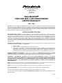
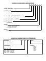
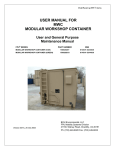
1
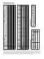
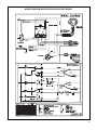
Service & Parts Manual
WallMaster ® Thru-the-Wall
WS08B10A-C
WS10B10A-C
WS14B10A-C
PM
WS10B30A-C
72
Power
Cool
Fan
Speed
Mode
®
Money Saver
Fan Only
Clock
On/Off
Timer
Hour
Set
Start Time
Stop Time
Temp/Hour
WS13B30B-C
WS16B30A-C
WE10B33A-B
WE13B33B-B
WE16B33A-B
WY10B33A-B
WY13B33A-B
WM-Svc-Prts-07 (3-07)
TABLE OF CONTENTS
Warranty .....................................................................................................................................................3
Routine Maintenance ................................................................................................................................4
Unit Identification ......................................................................................................................................5
Performance Data .....................................................................................................................................6
Electrical Data ...........................................................................................................................................7
Functional Component Definitions .........................................................................................................8
Electronic Controls ...................................................................................................................................9
Rotary Controls .......................................................................................................................................10
Refrigeration Sequence of Operation ...................................................................................................11
Sealed Refrigeration Repairs ........................................................................................................... 12-13
Refrigerant Charging ..............................................................................................................................13
General Troubleshooting.................................................................................................................. 14-20
Wiring Diagrams ................................................................................................................................ 21-25
Parts Diagram ..........................................................................................................................................26
Parts Lists .......................................................................................................................................... 27-29
2
Friedrich Air Conditioning Company
P.O. Box 1540
San Antonio, TX 78295
210.357.4400
www.friedrich.com
WALLMASTER£
THRU-THE-WALL AIR CONDITIONERS
LIMITED WARRANTY
FIRST YEAR
ANY PART: If any part supplied by FRIEDRICH fails because of a defect in workmanship or material within twelve months from
date of original purchase, FRIEDRICH will repair the product at no charge, provided room air conditioner is reasonably accessible
for service. Any additional labor cost for removing inaccessible units and/or charges for mileage related to travel by a Service
Agency that exceeds 25 miles one way will be the responsibility of the owner. This remedy is expressly agreed to be the exclusive
remedy within twelve months from the date of the original purchase.
SECOND THROUGH FIFTH YEAR
SEALED REFRIGERANT SYSTEM: If the Sealed Refrigeration System (defined for this purpose as the compressor, condenser
coil, evaporator coil, reversing valve, check valve, capillary, filter drier, and all interconnecting tubing) supplied by FRIEDRICH in
your Room Air Conditioner fails because of a defect in workmanship or material within sixty months from date of purchase,
FRIEDRICH will pay a labor allowance and parts necessary to repair the Sealed Refrigeration System; PROVIDED FRIEDRICH will
not pay the cost of diagnosis of the problem, removal, freight charges, and transportation of the air conditioner to and from the
Service Agency, and the reinstallation charges associated with repair of the Sealed Refrigeration System. All such cost will be the
sole responsibility of the owner. This remedy is expressly agreed to be the exclusive remedy within sixty months from the date of the
original purchase.
APPLICABILITY AND LIMITATIONS: This warranty is applicable only to units retained within the Fifty States of the U.S.A., District
of Columbia, and Canada. This warranty is not applicable to:
1.
2.
3.
Air filters or fuses.
Products on which the model and serial numbers have been removed.
Products which have defects or damage which results from improper installation, wiring, electrical current
characteristics, or maintenance; or caused by accident, misuse or abuse, fire, flood, alterations and/or misapplication
of the product and/or units installed in a corrosive atmosphere, default or delay in performance caused by war,
government restrictions or restraints, strikes, material shortages beyond the control of FRIEDRICH, or acts of God.
OBTAINING WARRANTY PERFORMANCE: Service will be provided by the FRIEDRICH Authorized Dealer or Service
Organization in your area. They are listed in the Yellow Pages. If assistance is required in obtaining warranty performance, write
to: Room Air Conditioner Service Manager, Friedrich Air Conditioning Co., P.O. Box 1540, San Antonio, TX 78295-1540.
LIMITATIONS:
THIS WARRANTY IS GIVEN IN LIEU OF ALL OTHER WARRANTIES. Anything in the warranty
notwithstanding, ANY IMPLIED WARRANTIES OF FITNESS FOR PARTICULAR PURPOSE AND/OR MERCHANTABILITY
SHALL BE LIMITED TO THE DURATION OF THIS EXPRESS WARRANTY. MANUFACTURER EXPRESSLY DISCLAIMS AND
EXCLUDES ANY LIABILITY FOR CONSEQUENTIAL OR INCIDENTAL DAMAGE FOR BREACH OF ANY EXPRESSED OR
IMPLIED WARRANTY.
NOTE: Some states do not allow limitations on how long an implied warranty lasts, or do not allow the limitation or exclusion of
consequential or incidental damages, so the foregoing exclusions and limitations may not apply to you.
OTHER: This warranty gives you specific legal rights, and you may also have other rights which vary from state to state.
PROOF OF PURCHASE: Owner must provide proof of purchase in order to receive any warranty related services.
All service calls for explaining the operation of this product will be the sole responsibility of the consumer.
All warranty service must be provided by an Authorized FRIEDRICH Service Agency, unless authorized by FRIEDRICH prior to
repairs being made.
(10-04)
3
ROUTINE MAINTENANCE
NOTE: Units are to be inspected and serviced by qualified service personnel only.
Routine maintenance is required annually or semi-annually, depending upon annual usage.
1. Clean the unit air intake filter at least every 250 to 300 fan hours of operation or when the unit’s indicator light is on if
so equipped. Clean the filters with a mild detergent in warm water and allow to dry thoroughly before reinstalling.
2.
The indoor coil (evaporator coil), the outdoor coil (condenser coil) and base pan should be inspected periodically (yearly
or bi-yearly) and cleaned of all debris (lint, dirt, leaves, paper, etc.). Clean the coils and base pan with a soft brush and
compressed air or vacuum. If using a pressure washer, be careful not to bend the aluminium fin pack. Use a sweeping
up and down motion in the direction of the vertical aluminum fin pack when pressure cleaning coils. Cover all electrical
components to protect them from water or spray. Allow the unit to dry thoroughly before reinstalling it in the sleeve.
NOTE: Do not use a caustic coil cleaning agent on coils or base pan. Use a biodegradable cleaning agent and degreaser.
Inspect the indoor blower housing, evaporator blade, condenser fan blade, and condenser shroud periodically (yearly or
bi-yearly) and clean of all debris (lint, dirt, mold, fungus, etc.) Clean the blower housing area and blower wheel with an
antibacterial / antifungal cleaner. Use a biodegradable cleaning agent and degreaser on condenser fan and condenser
shroud. Use warm or cold water when rinsing these items. Allow all items to dry thoroughly before reinstalling them.
3.
Periodically (at least yearly or bi-yearly): inspect all control components, both electrical and mechanical, as well as the
power supply. Use proper testing instruments (voltmeter, ohmmeter, ammeter, wattmeter, etc.) to perform electrical
tests. Use an air conditioning or refrigeration thermometer to check room, outdoor and coil operating temperatures.
Use a sling psychrometer to measure wet bulb temperatures indoors and outdoors.
4.
Inspect the surrounding area (inside and outside) to ensure that the units’ clearances have not been compromised or
altered.
5.
Inspect the sleeve and drain system periodically (at least yearly or bi-yearly) and clean of all obstructions and debris.
Clean both areas with an antibacterial and antifungal cleaner. Rinse both items thoroughly with water and ensure that
the drain outlets are operating correctly. Check the sealant around the sleeve and reseal areas as needed.
6.
Clean the front cover when needed. Use a mild detergent. Wash and rinse with warm water. Allow it to dry thoroughly
before reinstalling it in the chassis.
4
FRIEDRICH ROOM MODEL NUMBER CODE
W
S
08
B
1
0
B
1st DIGIT - FUNCTION
W = Thru-The-Wall, WallMaster Series
2nd DIGIT - TYPE
S = Straight Cool
E = Electric Heat
Y = Heat Pump
3rd & 4th DIGITS - APPROXIMATE BTU/HR (Cooling)
Heating BTU/HR capacity listed in Specifications/Performance Data Section
5th DIGIT - ALPHABETICAL MODIFIER
6th DIGIT - VOLTAGE
1 = 115 Volts
3 = 230-208 Volts
7th DIGIT
0 = Straight Cool & Heat Pump Models
ELECTRIC HEAT MODELS
3 = 3 KW Heat Strip, Nominal
8th DIGIT
Major Change
RAC SERIAL NUMBER IDENTIFICATION GUIDE
Serial Number
Decade Manufactured
L=0
C=3
F=6
A=1
D=4
G=7
B=2
E=5
H=8
Year Manufactured
A=1
D=4
G=7
L
J=9
K=0
C
G
R
00001
Production Run Number
Product Line
R = RAC
B=2
E=5
H=8
P = PTAC
C=3
F=6
J=9
E = EAC
Month Manufactured
A=Jan D=Apr G=Jul
B=Feb
V = VPAK
K=Oct
H = Split
E=May H=Aug L=Nov
C=Mar F=Jun
J=Sept M=Dec
5
6
Cooling
Capacity
BTU/h
8000
10000
13500
10000/10000
12500/12000
15800/15000
10000/10000
12500/12000
15800/15000
10100/9800
12500/12100
Model #
WS08B10A
WS10B10A
WS14B10A
WS10B30A
WS13B30B
WS16B30A
WE10B33A
WE13B33B
WE16B33A
WY10B33A
WY13B33A
25
28
28
25
29
28
27
29
28
27
29
—
—
—
—
—
—
11000/9100
11000/9100
11000/9100
8100/7800
10400/10000
Heating
Capacity
BTU/h
55
53
52
53
52
51
54
52
51
54
52
E(in)
125V - 15A
250V - 15A
250V - 20A
WS08B10A, WS10B10A,
WS14B10A
WS10B30A, WS13B30A,
WS16B30A
WE10, WE13, WE16
WY10, WY13
Model Numbers
Circuit Rating
Breaker
or T-D Fuse
55
51
52
57
50
53
52
51
53
52
51
6 - 20P
6 - 15P
5 - 15P
Plug Face
(NEMA#)
115
115
115
230/208
230/208
230/208
230/208
230/208
230/208
230/208
230/208
Volts Rated
127
128
128
131
128
121
126
127
121
126
127
61
68
63
68
57
54
82
64
57
66
64
Suction
Temp
Wall
Outlet
Appearance
6.8
8.7
12.0
4.6/5.0
6.3/6.7
7.8/8.5
4.6/5.0
6.3/6.7
7.8/8.5
4.6/4.8
6.4/6.8
Cooling
Amps
165
176
179
179
174
154
180
180
174
180
180
CONDENSER
TEMP.
Discharge
E (out)
DEG. F
Temp
EVAPORATOR
TEMP. DEG. F
Installation Information
55
52
52
55
51
52
53
52
52
53
52
WS08B10A
WS10B10A
WS14B10A
WS10B30A
WS13B30B
WS16B30A
WE10B33A
WE13B33B
WE16B33A
WY10B33A
WY13B33A
Discharge Temp.
Air
Drop F.
EVAPORATOR AIR
TEMP. DEG. F
762
954
1415
1005/996
1404/1379
1756/1705
1005/996
1404/1379
1756/1705
1013/976
1389/1352
Cooling
Watts
102
105
99
106
100
99
99
103
100
99
103
Liquid
Temp
18
16
14
16
13
18
16
13
18
16
16
—
—
—
—
—
—
3550/2950
3550/2950
3550/2950
857/821
1182/1136
—
—
—
—
—
—
16.0/14.7
16.0/14.7
16.0/14.7
3.9/4.0
5.4/5.7
281
293
297
289
295
315
289
295
315
225
300
Heating
Watts
87
79
82
77
78
74
82
80
74
82
80
Heating
Amps
25
24
28
23
30
32
31
29
30
31
29
WSC Sleeve
Chassis
Model
Width
27"
26 1/2"
Height
16 3/4"
15 3/4"
Depth
16 3/4"
21"
23"
–
Depth
with
Front
Energy
Efficiency
Ratio
EER
7.1
9.0
12.4
4.6
6.5
7.7
4.6
15.2
6.5
15.7
6.5
16.1
4.6
4 / 15.2
6.5 5.6 / 15.7
10.5
10.5
9.5
10.0/10.0
8.9/8.7
9.0/8.8
10.0/10.0
8.9/8.7
9.0/8.8
10.0/10.0
9.0/9.0
R-22 REF.
7 1/2"
–
Minimum
Extension
Into Room
1.3
2.4
3.3
2.1
3.3
4.2
2.1
3.3
4.2
2.5
3.2
Moisture
Removal
Pints/Hr.
36.2
45.0
58.0
26.0
27.4
35.0
45.0
27.4
35.0
26.0
27.4
257
248
293
235
281
292
225
274
281
225
260
9/16"
–
Minimum
Extension
Outside
245
245
295
260
280
290
260
280
290
230
280
Room
Side Air
Circulation
20.5
22.0
44.9
22.5
35.2
47.6
38.0
35.0
35.2
38.0
35.0
Amps
Locked Charge in Evap
Heat Rotor Amps OZ.
CFM
ELECTRICAL RATINGS
SubAmps
Cooling Suction Discharge Cool
Sleeve Dimensions
Super
Heat
OPERATING
PRESSURES
15
15
15
15
15
15
20
20
20
20
20
17 1/4"
–
27 1/4"
–
Thru-the-wall
Finished Hole
Height
Width
93
103
112
101
109
119
103
111
121
107
116
Net Weight
Lbs.
1100
1100
1300
1100
1300
1421
1074
1318
1305
1074
1200
Motor 60 Hertz
RPM
Amps
BREAKER
FUSE
PERFORMANCE DATA
* Rating Conditions: 80 degrees F, room air temp. & 50% relative humidity, with 95 degree F, outside air temp & 40% relative humidity
Calculate the heat loss of the space to be heated. As long as the heat loss does not exceed the resistance heating capacity rating of the unit, the heating performance will be satisfactory. Change-over
from heat pump operation to resistance operation on models indicated is automatic at a preset outside ambient temperature of approximately 35°F. If condensate disposal is desired, an optional drain
kit is available. DEFROST CONTROL: Initiated at 20°F (outdoor coil temperature) and terminated at 43°F (outdoor coil temperature). During defrost, the compressor stops and the electric heat starts,
then operates with the fan to maintain indoor comfort. Below 43°F, the unit remains in electric heat mode. During electric heat mode, the unit will achieve the following ratings: 11000/9100 BTU/h,
16.0/14.7 amps, and 3550/2950 watts. DEFROST DRAIN: Drain automatically opens at approximately 50°F in outdoor base pan for defrost condensate disposal.
ELECTRICAL DATA
Wire Size
Use ONLY wiring size recommended for
single outlet branch circuit.
Fuse/Circuit
Use ONLY type and size fuse or HACR
Breaker
circuit breaker indicated on unit’s rating
plate. Proper current protection to the unit
is the responsibility of the owner.
Grounding
Receptacle
Unit MUST be grounded from branch
circuit through service cord to unit, or
through separate ground wire provided on
permanently connected units. Be sure that
branch circuit or general purpose outlet is
grounded.
ELECTRIC SHOCK HAZARD.
Turn off electric power before service or installation.
All electrical connections and wiring MUST be
installed by a qualified electrician and conform to the
National Electrical Code and all local codes which
have jurisdiction.
Failure to do so can result in property damage,
personal injury and/or death.
The field supplied outlet must match plug on
service cord and be within reach of service
cord. Do NOT alter the service cord or plug.
Do NOT use an extension cord. Refer to
the table above for proper receptacle and
fuse type.
The consumer - through the AHAM Room Air Conditioner Certification Program - can be certain
that the AHAM Certification Seal accurately states the unit’s cooling and heating capacity rating,
the amperes and the energy efficiency ratio.
7
FUNCTIONAL COMPONENTS
A. Mechanical components
Bellows condensate valve
Temperature-sensitive valve that opens up to drain off condensate water when the outside temperature falls below 40°F
and closes when the outside temperature reaches 58°F.
Plenum assembly
Diffuser with directional louvers used to direct the conditioned airflow.
Blower wheel
Attaches to the indoor side of the fan motor shaft and is used for distributing unconditioned, room side air though the heat
exchanger and delivering conditioned air into the room.
Slinger fan blade
Attaches to the outdoor side of the fan motor shaft and is used to move outside air through the condenser coil, while
slinging condensate water out of the base pan and onto the condenser coil, thus lowering the temperature and pressures
within the coil.
B. Electrical components
Thermostat
Used to maintain the specified room side comfort level
System switch
Used to regulate the operation of the fan motor, the compressor or to turn the unit off. For troubleshooting, refer to the
wiring diagrams and schematics in the back of this service manual.
Capacitor
Reduces line current and steadies the voltage supply, while greatly improving the torque characteristics of the fan motor
and compressor motor.
MoneySaver® switch
When engaged, it sends the power supply to the fan motor through the thermostat, which allows for a cycle-fan operation.
Fan Motor
Dual-shafted fan motor operates the indoor blower wheel and the condenser fan blade simultaneously.
Solenoid
Used to energize the reversing valve on all heat pump units.
Heating element
Electric resistance heater, available in 3.3, 4.0 or 5.2 kW on select TwinTemp® models.
Heat anticipator
Used to provide better thermostat and room air temperature control.
C. Hermetic components
Compressor
Motorized device used to compress refrigerant through the sealed system.
Reversing valve
A four-way switching device used on all heat pump models to change the flow of refrigerant to permit heating or cooling.
Check valve
A pressure-operated device used to direct the flow of refrigerant to the proper capillary tube, during either the heating or
cooling cycle.
Capillary tube
A cylindrical meter device used to evenly distribute the flow of refrigerant to the heat exchangers (coils.)
8
SYSTEM CONTROL PANEL
(“WS” Models)
Figure 6: System Control Panel
Activating Error Code Mode (Submode of Test Mode)
Unit must be in Test Mode to enter Error Code Mode
1.
PM
72
Power
Cool
Fan
Speed
Mode
Money Saver®
Fan Only
Clock
Timer
On/Off
Set
Hour
Start Time
Stop Time
Temp/Hour
Activate Error Code Mode by pressing the “TIMER
ON/OFF” button on XQ & WS models. LED for the
“TIMER ON/OFF” will flash 1bps while Error Code
Mode is active. Pressing the “TEMP/HR + ” button will
display 00. Consecutive presses will scroll through all
error codes logged. Press the “TEMP/HR - ” button
to see the reverse order of all error codes logged.
When the end of logged error codes is reached the
temperature set point will appear.
IMPORTANT
Error Codes are cleared from the log by exiting from Error
Code Mode. To exit on XQ & WS models, press Timer On/
Off button. Or unplug unit to exit Error Code Mode. Plug
unit in after 5 seconds to resume normal operation of unit.
ERROR CODE LISTINGS
TESTING THE ELECTRONIC CONTROL
CHECKING ROOM TEMPERATURE
1. Check the room temperature at the electronic control
pad by pressing at the same time the “FAN SPEED”
button and the temperature “UP” button on XQ & WS
models.
2. The indoor temperature will display for 10 seconds.
Indoor temperature can be viewed in all modes,
including the TEST mode. The display can be changed
back to SET temperature by pressing any key, except
the ON/OFF button, or after 10seconds has elapsed.
ACTIVATING TEST MODE
Activate test mode by pressing at the same time the “MODE”
button and the temperature “DOWN” button on XQ & WS
models. LEDs for Hour, Start, and Stop will blink 1bps while
Test Mode is active.
Test Mode has duration of 90 minutes. Test Mode
can be activated under any conditions, including Off.
Test Mode is cancelled by pressing the On/Off button,
unplugging the unit, or when the 90 minutes is timed
out. All settings revert to the factory default settings of
Cool, 75 degrees F, Timer and Set Hour features are
nonfunctional.
Test Mode overrides the three-minute lockout, all delays
for compressor and fan motor start / speed change, and
no delay when switching modes.
E1
SHORT CYCLE SITUATION:
Defined as
compressor powered on before the three minute
time delay ten times in one hour. Investigate and
correct short cycling problem.
E2
KEYBOARD STUCK ERROR: If key button(s)
are pressed continuously for twenty seconds or
more. If MODE key is stuck, unit will default to
cool. Exit Error Code Mode to see if error “E2”
is no longer displayed and unit is functioning.
Replace board if “E2” still displays after exiting
Error Code Mode.
E3
FROST PROBE OPEN: Normal operation is
allowed. Ohm frost probe. Replace probe if ohm
value not read. If ohm value present replace
board.
E4
FROST PROBE SHORT:
allowed. Replace probe.
E5
INDOOR PROBE OPEN: Control assumes
indoor ambient temperature is 90 degree F and
unit will operate. Ohm indoor probe. Replace
probe if ohm value not read.
E6
INDOOR PROBE SHORT: Control assumes
ambient temperature is 90 degree F and unit will
operate. Replace probe.
Normal operation
NOTE: All Error Code displays for Frost & Indoor Probe
will allow unit to operate. Unit may or will ice up if faulty
components not replaced.
Test Mode default settings are ON, Money Saver, 60
degrees F, and High fan speed.
9
Frost Probe Sensor: Disables compressor at 35 degrees
F +/- 3 degrees F
Indoor Probe Sensor: Control range is 60 degrees F to 90
degrees F +/- 2 degrees F
Indoor temperature will be displayed by pressing:
(XQ / WS Units) The Fan Speed button and the Temp Up
button.
The indoor temperature will be displayed for 10 seconds.
The display will change back to the Set Point temperature by
pressing any key button except for the On/Off button. The
indoor temperature can be viewed in all modes, including
test mode.
Keep Alive: The electronic control has a memory to retain
all functions and status as set up by the user in the event
of a power failure. Once power is restored to the unit
there is a two second delay before the fan comes on and
approximately three minutes delay before the compressor
is activated, providing that the mode was set for cooling and
the set point temperature has not been met in the room.
SYSTEM CONTROL SWITCH
(“WE” & “WY” Models)
An eight position switch is used to regulate the operation
of the fan motor, compressor and electric heater.
The unit can be operated in cooling or heating mode with
the compressor or electric heater on and the fan motor
operating on low, medium or high speed.
SYSTEM CONTROL SWITCH - TEST
Disconnect leads from control switch. Turn control to position being tested (see Figure 8). There must be continuity
as follows:
1. “Off” Position-no continuity between terminals.
2. “Lo Cool” Position-between terminals “C” and “3”,
“C2” and “2”, “LO” and “M/S”, “AR” and “5”.
3. “Med Cool” Position-between terminals “C” and “3”,
“C2” and “2”, “M” and “M/S”, “AR” and “5”.
4. “Hi Cool” Position-between terminals “C” and “3”,
“C2” and “2”, “H” and “M/S”, “AR” and “5”.
5. “Hi Heat” Position-between terminals “C” and “1”,
“C2” and “4”, “H” and “M/S”, “AR” and “5”.
6. “Med Heat” Position-between terminals “C” and “1”,
“C2” and “4”, “M” and “M/S”, “AR” and “5”.
7. “Lo Cool” Position-between terminals “C” and “1”,
“C2” and “4”, “LO” and “M/S”, “AR” and “5”.
8. “Fan Only” Position-between terminals “L1”, “M”
and “2”.
Figure 8: System Control Switch
(Heat Pump & Electric Heat Models)
The fan motor can also be operated independently on
medium speed. See switch section as indicated on
decorative control panel, in Figure 7.
Figure 7: System Control Panel
Fan
Only
Low
Heat
Med
Heat
High
Heat
NOTE:
Units will operate in constant fan in the cooling mode and
auto fan in the heating mode.
Off
Low
Cool
Med
Cool
High
Cool
! Allow 3 min. between restarts
10
MAX
HEAT
MAX
COOL
REFRIGERATION SYSTEM SEQUENCE OF OPERATION
A good understanding of the basic operation of the refrigeration system is essential for the service technician. Without
this understanding, accurate troubleshooting of refrigeration
system problems will be more difficult and time consuming,
if not (in some cases) entirely impossible. The refrigeration
system uses four basic principles (laws) in its operation they
are as follows:
1.
“Heat always flows from a warmer body to a cooler
body.”
2. “Heat must be added to or removed from a substance
before a change in state can occur”
3. “Flow is always from a higher pressure area to a lower
pressure area.”
4.
“The temperature at which a liquid or gas changes state
is dependent upon the pressure.”
The refrigeration cycle begins at the compressor. Starting
the compressor creates a low pressure in the suction line
which draws refrigerant gas (vapor) into the compressor.
The compressor then “compresses” this refrigerant, raising
its pressure and its (heat intensity) Temperature.
The refrigerant leaves the compressor through the discharge
line as a hot high pressure gas (vapor). The refrigerant enters
the condenser coil where it gives up some of its heat. The
condenser fan moving air across the coil’s finned surface
facilitates the transfer of heat from the refrigerant to the
relatively cooler outdoor air.
When a sufficient quantity of heat has been removed from
the refrigerant gas (vapor), the refrigerant will “condense”
(i.e. change to a liquid). Once the refrigerant has been
condensed (changed) to a liquid it is cooled even further by
the air that continues to flow across the condenser coil.
The RAC design determines at exactly what point (in the
condenser) the change of state (i.e. gas to a liquid) takes
place. In all cases, however, the refrigerant must be totally
condensed (changed) to a liquid before leaving the condenser
coil.
The refrigerant leaves the condenser coil through the
liquid line as a warm high pressure liquid. It next will pass
through the refrigerant drier (if so equipped). It is the
function of the drier to trap any moisture present in the
system, contaminants, and large particulate matter.
The liquid refrigerant next enters the metering device. The
metering device is a capillary tube. The purpose of the
metering device is to “meter” (i.e. control or measure) the
quantity of refrigerant entering the evaporator coil.
In the case of the capillary tube this is accomplished
(by design) through size (and length) of device, and the
pressure difference present across the device.
Since the evaporator coil is under a lower pressure (due to
the suction created by the compressor) than the liquid line,
the liquid refrigerant leaves the metering device entering
the evaporator coil. As it enters the evaporator coil, the
larger area and lower pressure allows the refrigerant to
expand and lower its temperature (heat intensity). This
expansion is often referred to as “boiling”. Since the unit’s
blower is moving Indoor air across the finned surface of
the evaporator coil, the expanding refrigerant absorbs
some of that heat. This results in a lowering of the indoor
air temperature, hence the “cooling” effect.
The expansion and absorbing of heat cause the liquid
refrigerant to evaporate (i.e. change to a gas). Once the
refrigerant has been evaporated (changed to a gas), it is
heated even further by the air that continues to flow across
the evaporator coil.
The particular system design determines at exactly what
point (in the evaporator) the change of state (i.e. liquid to a
gas) takes place. In all cases, however, the refrigerant must
be totally evaporated (changed) to a gas before leaving
the evaporator coil.
The low pressure (suction) created by the compressor
causes the refrigerant to leave the evaporator through the
suction line as a cool low pressure vapor. The refrigerant
then returns to the compressor, where the cycle is
repeated.
Refrigerant System Components
Suction
Line
Discharge
Line
Evaporator
Coil
Condenser
Coil
Compressor
Metering
Device
Refrigerant Drier
Liquid
Line
SEALED REFRIGERATION SYSTEM REPAIRS
IMPORTANT
ANY SEALED SYSTEM REPAIRS TO COOL-ONLY
MODELS REQUIRE THE INSTALLATION OF A
LIQUID LINE DRIER. ALSO, ANY SEALED SYSTEM
REPAIRS TO HEAT PUMP MODELS REQUIRE THE
INSTALLATION OF A SUCTION LINE DRIER.
11
SEALED REFRIGERATION SYSTEM
REPAIRS
EQUIPMENT REQUIRED:
1. Voltmeter
HERMETIC COMPONENT REPLACEMENT
The following procedure applies when replacing components in the sealed refrigeration circuit or repairing
refrigerant leaks. (Compressor, condenser, evaporator,
capillary tube, refrigerant leaks, etc.)
1.
Recover the refrigerant from the system at the process tube located on the high side of the system by
installing a line tap on the process tube. Apply gauge
from process tube to EPA approved gauges from
process tube to EPA approved recovery system.
Recover CFCs in system to at least 5%.
2.
Cut the process tube below pinch off on the suction
side of the compressor.
3.
Connect the line from the nitrogen tank to the suction
process tube.
4.
Drift dry nitrogen through the system and unsolder
the more distant connection first. (Filter drier, high
side process tube, etc.)
5.
Replace inoperative component, and always install a
new filter drier. Drift dry nitrogen through the system
when making these connections.
6.
Pressurize system to 30 PSIG with proper refrigerant
and boost refrigerant pressure to 150 PSIG with dry
nitrogen.
1. Evacuation from both the high side and low side of
the system simultaneously.
7.
Leak test complete system with electric halogen leak
detector, correcting any leaks found.
2. Introducing refrigerant charge into high side of the
system.
8.
Reduce the system to zero gauge pressure.
9.
Connect vacuum pump to high side and low side of
system with deep vacuum hoses, or copper tubing.
(Do not use regular hoses.)
2. Ammeter
3. Ohmmeter
4. Vacuum Pump (capable of 200 microns or less
vacuum.)
5. Acetylene Welder
6. Electronic Halogen Leak Detector (G.E. Type H-6 or
equivalent.)
7. Accurate refrigerant charge measuring device such
as:
a. Balance Scales - 1/2 oz. accuracy
b. Charging Board - 1/2 oz. accuracy
8. High Pressure Gauge - (0 - 400 lbs.)
9. Low Pressure Gauge - (30 - 150 lbs.)
10. Vacuum Gauge - (0 - 1000 microns)
EQUIPMENT MUST BE CAPABLE OF:
3. Accurately weighing the refrigerant charge actually
introduced into the system.
4. Facilities for flowing nitrogen through refrigeration
tubing during all brazing processes.
12
10.
11.
Evacuate system to maximum absolute holding pressure of 200 microns or less. NOTE: This process can
be speeded up by use of heat lamps, or by breaking
the vacuum with refrigerant or dry nitrogen at 5,000
microns. Pressure system to 5 PSIG and leave in
system a minimum of 10 minutes. Release refrigerant, and proceed with evacuation of a pressure of
200 microns or less.
Break vacuum by charging system from the high side
with the correct amount of refrigerant specified. This
will prevent boiling the oil out of the crankcase.
NOTE: If the entire charge will not enter the high
side, allow the remainder to enter the low side in
small increments while operating the unit.
12.
Restart unit several times after allowing pressures
to stabilize. Pinch off process tubes, cut and solder
the ends. Remove pinch off tool, and leak check the
process tube ends.
ROTARY COMPRESSOR SPECIAL
TROUBLESHOOTING AND SERVICE
Basically, troubleshooting and servicing rotary compressors is the same as on the reciprocating compressor with
only a few exceptions.
1.
Because of the spinning motion of the rotary, the
mounts are critical. If vibration is present, check the
mounts carefully.
2.
The electrical terminals on the rotary are in a different order than the reciprocating compressors. The
terminal markings are on the cover gasket. Use your
wiring diagram to insure correct connections.
REFRIGERANT CHARGE
1. The refrigerant charge is extremely critical. Measure charge carefully - as exact as possible to the
nameplate charge.
2.
SPECIAL PROCEDURE IN THE CASE OF MOTOR
COMPRESSOR BURNOUT
1. Recover all refrigerant and oil from the system.
2.
Remove compressor, capillary tube and filter drier
from the system.
3.
Flush evaporator condenser and all connecting
tubing with dry nitrogen or equivalent, to remove
all contamination from system. Inspect suction and
discharge line for carbon deposits. Remove and
clean if necessary.
4.
Reassemble the system, including new drier strainer
and capillary tube.
5.
Proceed with processing as outlined under hermetic
component replacement.
The correct method for charging the rotary is to
introduce liquid refrigerant into the high side of the
system with the unit off. Then start compressor and
enter the balance of the charge, gas only, into the
low side.
The introduction of liquid into the low side, without
the use of a capillary tube, will cause damage to
the discharge valve of the rotary compressor.
NOTE: All inoperative compressors returned to
Friedrich must have all lines properly plugged with
the plugs from the replacement compressor.
13
TROUBLESHOOTING TOUCH TEST CHART: TO SERVICE REVERSING VALVES
Tube to OUTSIDE
COIL
LEFT Pilot
Capillary Tube
RIGHT Pilot
Capillary Tube
1
2
3
4
5
6
Hot
as (1)
*TVB
TVB
Cool
as (2)
*TVB
TVB
Tube to INSIDE
COIL
SUCTION TUBE to
Compressor
VALVE
OPERATING
CONDITION
DISCHARGE TUBE
from Compressor
NORMAL FUNCTION OF VALVE
Normal Cooling
Hot
Cool
Cool
as (2)
Normal Heating
Hot
Cool
Hot
as (1)
NOTES:
* TEMPERATURE OF VALVE BODY
** WARMER THAN VALVE BODY
POSSIBLE CAUSES
CORRECTIONS
MALFUNCTION OF VALVE
Check Electrical circuit and coil
Check refrigeration charge
Valve will not
shift from cool
to heat.
Valve will not
shift from cool
to heat.
Starts to shift
but does not
complete
reversal.
Apparent
leap in heating.
Hot
Cool
Hot,
as (1)
*TVB
Repair electrical circuit.
Defective coil.
Replace coil.
Low charge.
Repair leak, recharge system.
Pressure differential too high.
Recheck system.
Hot
Pilot valve okay. Dirt in one bleeder hole.
Hot
Cool
Cool,
as (2)
Hot,
as (1)
*TVB
*TVB
Hot
Cool
Cool,
as (2)
Hot,
as (1)
Hot
Hot
Warm
Cool
Cool,
as (2)
Hot,
as (1)
*TVB
Warm
Hot
Warm
Warm
Hot
*TVB
Hot
Deenergize solenoid, raise head pressure,
reenergize solenoid to break dirt loose.
If unsuccessful, remove valve, wash
out. Check on air before installing. If no
movement, replace valve, add strainer to
discharge tube, mount valve horizontally.
Piston cup leak
Stop unit. After pressures equalize, restart
with solenoid energized. If valve shifts,
reattempt with compressor running. If still
no shift, replace valve.
Clogged pilot tubes.
Raise head pressure, operate solenoid to
free. If still no shift, replace valve.
Both ports of pilot open. (Back seat port
did not close).
Raise head pressure, operate solenoid to free
partially clogged port. If still no shift, replace
valve.
Defective Compressor.
Replace compressor
Not enough pressure differential at start
of stroke or not enough flow to maintain
pressure differential.
Check unit for correct operating pressures
and charge. Raise head pressure. If no
shift, use valve with smaller port.
Body damage.
Replace valve
Hot
Warm
Warm
Hot
Hot
Hot
Both ports of pilot open.
Raise head pressure, operate solenoid. If
no shift, use valve with smaller ports.
Hot
Hot
Hot
Hot
*TVB
Hot
Body damage.
Replace valve
Valve hung up at mid-stroke. Pumping
volume of compressor not sufficient to
maintain reversal.
Raise head pressure, operate solenoid. If
no shift, use valve with smaller ports.
Both ports of pilot open.
Raise head pressure, operate solenoid. If no
shift, replace valve.
Piston needle on end of slide leaking.
Operate valve several times, then recheck.
If excessive leak, replace valve.
Pilot needle and piston needle leaking.
Operate valve several times, then recheck.
If excessive leak, replace valve.
Pressure differential too high.
Stop unit. Will reverse during equalization
period. Recheck system
Clogged pilot tube.
Raise head pressure, operate solenoid to
free dirt. If still no shift, replace valve.
Dirt in bleeder hole.
Raise head pressure, operate solenoid.
Remove valve and wash out. Check on air
before reinstalling, if no movement, replace
valve. Add strainer to discharge tube.
Mount valve horizontally.
Hot
Hot
Hot
Hot
Hot
Hot
Hot
Cool
Hot,
as (1)
Cool,
as (2)
*TVB
*TVB
Hot
Cool
Hot,
as (1)
Cool,
as (2)
Hot
Cool
Hot,
as (1)
Cool,
as (2)
** WVB ** WVB
*TVB
*TVB
Cool
Hot,
as (1)
Cool,
as (2)
Hot
Cool
Hot,
as (1)
Cool,
as (2)
Hot
*TVB
Piston cup leak.
Stop unit. After pressures equalize, restart
with solenoid deenergized. If valve shifts,
reattempt with compressor running. If it
still will not reverse while running, replace
the valve.
Hot
Cool
Hot,
as (1)
Cool,
as (2)
Hot
Hot
Defective pilot.
Replace valve.
Warm
Cool
Warm,
as (1)
Cool,
as (2)
Warm
*TVB
Defective compressor.
Replace compressor
Hot
Will not shift
from heat to
cool.
14
Cool,
as (2)
No voltage to coil.
Hot
*TVB
COOLING ONLY ROOM AIR CONDITIONERS: TROUBLESHOOTING TIPS
Problem
Compressor
does not run
Problem
Fan motor
does not run
Problem
Does not cool or
only cools slightly
Possible Cause
Action
Low voltage
Check voltage at compressor. 115V & 230V
units will operate at 10% voltage variance
T-stat not set cold enough or
inoperative
Set t-stat to coldest position. Test t-stat & replace if inoperative
Compressor hums but cuts off on
B10 overload
Hard start compressor. Direct test compressor.
If compressor starts, add starting components
Open or shorted compressor
windings
Check for continuity & resistance
Open overload
Test overload protector & replace if inoperative
Open capacitor
Test capacitor & replace if inoperative
Inoperative system switch
Test for continuity in all positions. Replace if
inoperative
Broken, loose or incorrect wiring
Refer to appropriate wiring diagrams to check
wiring
Possible Cause
Action
Inoperative system switch
Test switch & replace if inoperative
Broken, loose or incorrect wiring
Refer to applicable wiring diagram
Open capacitor
Test capacitor & replace if inoperative
Fan speed switch open
Test switch & replace if inoperative
Inoperative fan motor
Test fan motor & replace if inoperative (be sure
internal overload has had time to reset)
Possible Cause
Action
Undersized unit
Refer to industry standard sizing chart
T-stat open or inoperative
Set to coldest position. Test t-stat & replace if
necessary
Dirty filter
Clean as recommended in Owner's Manual
Dirty or restricted condenser or
evaporator coil
Use pressure wash or biodegradable cleaning
agent to clean
Poor air circulation
Adjust discharge louvers. Use high fan speed
Fresh air or exhaust air door open
on applicable models
Close doors. Instruct customer on use of this
feature
Low capacity - undercharge
Check for leak & make repair
Compressor not pumping properly
Check amperage draw against nameplate. If
not conclusive, make pressure test
15
Problem
Unit does not run
Problem
Evaporator coil
freezes up
Problem
Compressor runs
continually & does
not cycle off
Problem
Possible Cause
Fuse blown or circuit tripped
Power cord not plugged in
Plug it in
System switch in "OFF" position
Set switch correctly
Inoperative system switch
Test for continuity in each switch position
Loose or disconnected wiring at
switch or other components
Check wiring & connections. Reconnect per
wiring diagram
Possible Cause
Action
Dirty filter
Clean as recommended in Owner's Manual
Restricted airflow
Check for dirty or obstructed coil. Use
pressure wash or biodegradable cleaning
agent to clean
Inoperative t-stat
Test for shorted t-stat or stuck contacts
Short of refrigerant
De-ice coil & check for leak
Inoperative fan motor
Test fan motor & replace if inoperative
Partially restricted capillary tube
De-ice coil. Check temp. differential (delta T)
across coil. Touch test coil return bends for
same temp. Test for low running current
Possible Cause
Action
Excessive heat load
Unit undersized. Test cooling performance &
replace with larger unit if needed
Restriction in line
Check for partially iced coil & check
temperature split across coil
Refrigerant leak
Check for oil at silver soldered connections.
Check for partially iced coil. Check split across
coil. Check for low running amperage
T-stat contacts stuck
Check operation of t-stat. Replace if contacts
remain closed.
T-stat incorrectly wired
Refer to appropriate wiring diagram
Possible Cause
T-stat contacts stuck
T-stat does not turn T-stat set at coldest point
unit off
Incorrect wiring
Unit undersized for area to be
cooled
16
Action
Replace fuse, reset breaker. If repeats, check
fuse or breaker size. Check for shorts in unit
wiring & components
Action
Disconnect power to unit. Remove cover
of t-stat & check if contacts are stuck. If so,
replace t-stat
Turn to higher temp. setting to see if unit
cycles off
Refer to appropriate wiring diagrams
Refer to industry standard sizing chart
Problem
Compressor runs
for short periods
only. Cycles on
overload
Problem
T-stat does not
turn unit on
Problem
Noisy operation
Problem
Water leaks into
the room
Possible Cause
Action
Overload inoperative. Opens too
soon
Check operation of unit. Replace overload if
system operation is satisfactory
Compressor restarted before
system pressures equalized
Allow a minimum of 2 minutes to allow
pressures to equalize before attempting to
restart. Instruct customer of waiting period
Low or fluctuating voltage
Check voltage with unit operating. Check for
other appliances on circuit. Air conditioner
should be in separate circuit for proper voltage
& fused separately
Incorrect wiring
Refer to appropriate wiring diagram
Shorted or incorrect capacitor
Check by substituting a known good capacitor
of correct rating
Restricted or low air flow through
condenser coil
Check for proper fan speed or blocked
condenser
Compressor running abnormally
hot
Check for kinked discharge line or restricted
condenser. Check amperage
Possible Cause
Action
Loss of charge in t-stat bulb
Place jumper across t-stat terminals to check if
unit operates. If unit operates, replace t-stat.
Loose or broken parts in t-stat
Check as above
Incorrect wiring
Refer to appropriate wiring diagram
Possible Cause
Action
Poorly installed
Refer to Installation Manual for proper
installation
Fan blade striking chassis
Reposition - adjust motor mount
Compressor vibrating
Check that compressor grommets have not
deteriorated. Check that compressor mounting
parts are not missing
Improperly mounted or loose
cabinet parts
Check assembly & parts for looseness,
rubbing & rattling
Possible Cause
Action
Evaporator drain pan overflowing
Clean obstructed drain trough
Condensation forming on base pan
Evaporator drain pan broken or cracked.
Reseal or replace
Poor installation resulting in rain
entering the room
Check installation instructions. Reseal as
required
Condensation on discharge grille
louvers
Clean the dirty evaporator coil. Use pressure
wash or biodegradable cleaning agent to clean
Chassis gasket not installed
Install gasket, per Installation manual
Downward slope of unit is too
steep
Refer to installation manual for proper
installation
17
Problem
Water "spitting"
into room
Problem
Excessive moisture
Problem
T-stat short cycles
Problem
Prolonged off
cycles (automatic
operation)
Problem
Outside water
leaks
18
Possible Cause
Action
Sublimation:
When unconditioned saturated,
outside air mixes with conditioned
air, condensation forms on the
cooler surfaces
Ensure that foam gaskets are installed in
between window panes & in between the
unit & the sleeve. Also, ensure that fresh
air/exhaust vents (on applicable models) are in
the closed position & are in tact
Downward pitch of installation is
too steep
Follow installation instructions to ensure that
downward pitch of installed unit is no less than
1/4" & no more than 3/8"
Restricted coil or dirty filter
Clean & advise customer of periodic cleaning
& maintenance needs of entire unit
Possible Cause
Action
Insufficient air circulation thru area
to be air conditioned
Adjust louvers for best possible air circulation
Oversized unit
Operate in "MoneySaver" position
Inadequate vapor barrier in
building structure, particularly
floors
Advise customer
Possible Cause
Action
T-stat differential too narrow
Replace t-stat
Plenum gasket not sealing,
allowing discharge air to short
cycle t-stat
Check gasket. Reposition or replace as
needed
Restricted coil or dirty filter
Clean & advise customer of periodic cleaning
& maintenance needs of entire unit
Possible Cause
Action
Anticipator (resistor) wire
disconnected at t-stat or system
switch
Refer to appropriate wiring diagram
Anticipator (resistor) shorted or
open
Disconnect plus from outlet. Remove resistor
from bracket. Insert plug & depress "COOL"
& "FAN AUTOMATIC" buttons. Place t-stat to
warmest setting. Feel resistor for temperature.
If no heat, replace resistor
Partial loss of charge in t-stat bulb
causing a wide differential
Replace t-stat
Possible Cause
Action
Evaporator drain pan cracked or
obstructed
Repair, clean or replace as required
Water in compressor area
Detach shroud from pan & coil. Clean &
remove old sealer. Reseal, reinstall & check
Obstructed condenser coil
Use pressure wash or biodegradable cleaning
agent to clean
Fan blade/slinger ring improperly
positioned
Adjust fan blade to 1/2" of condenser coil
HEAT / COOL ROOM AIR CONDITIONERS: TROUBLESHOOTING TIPS
Problem
Room temperature
uneven
(Heating cycle)
Problem
Possible Cause
Heat anticipator (resistor) shorted
(on applicable models)
Disconnect power to unit. Remove resistor
from t-stat bulb block. Plus in unit & allow to
operate. Feel resistor for heat. If not heat,
replace resistor
Wide differential - partial loss of
t-stat bulb charge
Replace t-stat & check
Incorrect wiring
Refer to appropriate wiring diagram. Resistor
is energized during "ON" cycle of compressor
or fan.
Possible Cause
Refer to appropriate wiring diagram
Defrost control timer motor not
advancing (applicable models)
Check for voltage at "TM" & "TM1" on timer. If
no voltage, replace control
Defrost control out of calibration
(applicable models)
If outside coil temperature is 25°F or below,
& preselected time limit has elapsed, replace
defrost control
Defrost control contacts stuck
If contacts remain closed between terminals
"2" & "3" of the defrost control after
preselected time interval has passed, replace
control
Defrost control bulb removed from
or not making good coil contact
Reinstall & be assured that good bulb to coil
contact is made
Possible Cause
Exhaust or fresh air door open
Does not heat
adequately
Action
Incorrect wiring
Unit will not defrost
Problem
Action
Action
Check if operating properly. Instruct customer
on proper use of control
Dirty filter
Clean as recommended in Owner's Manual
Unit undersized
Check heat rise across coil. If unit operates
efficiently, check if insulation can be added
to attic or walls. If insulation is adequate,
recommend additional unit or larger one
Outdoor t-stat open (applicable
models)
T-stat should close at 38°F. Check continuity
of control. If temperature is below 38F, replace
control
Heater hi-limit control cycling on &
off
Check for adequate fan air across heater.
Check control for open at 160°F & close at
150°F
Shorted supplementary heater
Ohmmeter check, approx. 32-35 ohms
Incorrect wiring
Check applicable wiring diagram
19
Problem
Unit cools when
heat is called for
Problem
Cooling adequate,
but heating
insufficient
20
Possible Cause
Action
Incorrect wiring
Refer to applicable wiring diagram
Defective solenoid coil
Check for continuity of coil
Reversing valve fails to shift
Block condenser coil & switch unit to cooling.
Allow pressure to build up in system, then
switch to heating. If valve fails to shift, replace
valve.
Inoperative system switch
Check for continuity of system switch
Possible Cause
Action
Heating capillary tube partially
restricted
Check for partially starved outer coil. Replace
heating capillary tube
Check valve leaking internally
Switch unit several times from heating to
cooling. Check temperature rise across
coil. Refer to specification sheet for correct
temperature rise
Reversing valve failing to shift
completely; bypassing hot gas
Deenergize solenoid coil, raise head pressure,
energize solenoid to break loose. If valve fails
to make complete shift, replace valve.
WIRING DIAGRAM: MODELS WS08B10A-C, WS10B10A-C,
WS14B10A-C, WS10B30A-C, WS13B30C
21
WIRING DIAGRAM: MODELS WS16B30A-C
22
WIRING DIAGRAM: MODELS WE10B33A-B, WE13B33B-B
23
WIRING DIAGRAM: MODELS WE16B33A-B
24
WIRING DIAGRAM: MODELS WY10B33A-B, WY13B33A-B
25
26
46A
39
48
6
44
43
47
1
41
2
Electro
Mechanical
Control Box
and Controls
1
46
8
For Heat & Cool
Models Only
43
39
45
41
13
5
Electronic
Control Box
and Controls
18
27
19
20
12
25
26
31
32 30
7
16
17
14
WS, WE & WY SERIES CHASSIS PARTS
WALLMASTER PARTS 2007
* Part Not Shown
1
1
1
1
1
WY13B33A-B
WY10B33A-B
WE16B33A-B
1
1
WE13B33B-B
1
1
WE10B33A-B
WS16B30A-C
1
1
1
1
1
1
1
1
1
1
1
1
1
1
1
1
1
1
1
1
1
1
1
1
1
1
1
1
1
1
1
1
1
1
1
1
1
1
1
1
1
1
1
1
1
1
1
1
1
1
1
1
1
1
1
1
WE16B33A-B
WS16B30A-C
1
1
1
1
WE13B33B-B
1
WE10B33A-B
1
1
1
1
1
1
1
WY13B33A-B
25022032
61824400
60308101
61828200
61562832
62199700
62199701
62199702
62199703
62199704
62102300
62103300
62103303
62103305
62103400
62103401
62103402
62103500
62103501
03760513
03760547
01390000
03760550
03760511
03760548
1
WS13B30B-C
1
WS10B30A-C
1
CODE
WY10B33A-B
REVERSING VALVE and SOLENOID
CHECK VALVE
FILTER DRIER
SUCTION DRIER
COMPRESSOR
COMPRESSOR
COMPRESSOR
COMPRESSOR
COMPRESSOR
COMPRESSOR
EVAPORATOR COIL
EVAPORATOR COIL
EVAPORATOR COIL
EVAPORATOR COIL
CONDENSER COIL
CONDENSER COIL
CONDENSER COIL
CONDENSER COIL
CONDENSER COIL
CAPILLARY TUBE
CAPILLARY TUBE
CAPILLARY TUBE
CAPILLARY TUBE
CAPILLARY TUBE
CAPILLARY TUBE
1
WS13B30B-C
REFRIGERATION SYSTEM PARTS
10
11
*
*
12
12
12
12
12
12
13
13
13
13
14
14
14
14
14
*
*
*
*
*
*
1
WS10B30A-C
61921198
61921199
61826606
25043302
61350314
61764507
61764519
61764528
61764554
61764555
61764556
61080533
61080569
61080535
61080540
61080526
61080537
60500327
60500326
60500325
60607204
61871470
61871471
61871472
61871473
61871474
62101210
25022032
WS14B10A-C
ELECTRONIC BOARD
ELECTRONIC BOARD
REMOTE CONTROL
THERMOSTAT
THERMOSTAT, DEF.
OVERLOAD
OVERLOAD
OVERLOAD
OVERLOAD
OVERLOAD
OVERLOAD
CAPACITOR
CAPACITOR
CAPACITOR
CAPACITOR
CAPACITOR
CAPACITOR
SUPPLY CORD
SUPPLY CORD
SUPPLY CORD
SWITCH SYS. 8 POS.
FAN MOTOR
FAN MOTOR
FAN MOTOR
FAN MOTOR
FAN MOTOR
HEATER
SOLENOID and REVERSING VALVE
WS08B10A-C
1
1
*
1
2
3
3
3
3
3
3
4
4
4
4
4
4
5
5
5
6
7
7
7
7
7
8
9
230V
WS14B10A-C
ELECTRICAL PARTS
115V
WS10B10A-C
PART NO.
WS10B10A-C
DESCRIPTION
WS08B10A-C
REF
1
1
1
1
1
1
1
1
1
1
1
1
1
1
1
1
1
1
1
1
1
1
1
1
1
1
1
1
1
1
1
1
1
1
1
1
1
1
1
1
1
1
1
1
1
1
1
1
1
1
1
331
331
350
120
122
190
190
190
190
190
190
150
150
150
150
150
150
220
220
220
130
110
110
110
110
110
210
240
500
510
480
480
600
600
600
600
600
600
400
400
400
400
410
410
410
410
410
471
471
471
471
471
471
27
WALLMASTER PARTS 2007
1
WY13B33A-B
1
1
WY10B33A-B
1
1
1
WE16B33A-B
1
1
1
WE13B33B-B
START KIT
SLEEVE (ONLY)
GRILLE, STAMPED
1
1
1
WE10B33A-B
*
55
57
62102000
62101500
60610604
62100600
62100601
62102100
62100914
62100915
61606219
60179903
62101901
61028900
91400400
61715800
60640600
60640500
91003000
62100002
62100802
62101107
61911605
60865900
61900500
61925001
60865811
61607005
62103205
61612705
61612805
61613205
61578101
60846020
61717301
61841919
WS16B30A-C
SHROUD, CONDENSER
FAN BLADE, COND.
BLOWER WHEEL, EVAP.
BLOWER FRONT
BLOWER FRONT
SCROLL
BASE PAN
BASE PAN
BASE PAN ASLY.
BELLOWS,DRAIN VALVE
DRAIN PAN, ASSY.
GROMMET, comp.
BOLT, comp.
COUNTER WEIGHT
RETAINER CUP,FAN MTR
GROMMET,FAN MTR
NUT,FAN MTR
PANEL, CTRL. MOUNT
BRACKET CONRTOL
ESCUTCHEON, HTG/COOL
KNOBS, CRTL.
HOLDER, AIR FILTER
HOLDER, THERMOSTAT
HOLDER, THERMISTER
FILTER, AIR
FRONT COMPLETE
FRAME HOOD
GRILLE, INTAKE
GRILLE, EXHAUST
END CAP, GRILLE
WEATHER SEAL GASKET
HARDWARE, SCREWS
GASKET, CHASSIS
CARTON
CODE
WS13B30B-C
16
17
18
19
19
20
25
25
25
26
27
*
*
*
30
31
32
39
41
43
44
*
*
*
45
*
46
47
48
53
*
*
*
*
230V
WS10B30A-C
CHASSIS PARTS
115V
WS14B10A-C
PART NO.
WS10B10A-C
DESCRIPTION
WS08B10A-C
REF
1
1
1
1
1
1
1
1
1
1
1
1
1
1
1
1
1
1
1
1
1
1
1
1
1
1
1
1
1
1
1
1
1
1
1
1
1
1
1
1
1
1
1
1
1
1
1
1
1
1
1
1
3
3
2
3
3
3
1
1
1
2
2
1
1
1
1
3
3
2
3
3
3
1
1
1
2
2
1
1
1
1
3
3
2
3
3
3
1
1
1
2
2
1
1
1
1
3
3
2
3
3
3
1
1
1
2
2
1
1
1
1
3
3
2
3
3
3
1
1
1
2
2
1
1
3
3
2
3
3
3
1
1
1
3
3
2
3
3
3
1
1
1
3
3
2
3
3
3
1
1
1
3
3
2
3
3
3
1
1
1
3
3
2
3
3
3
1
1
1
3
3
2
3
3
3
1
1
2
2
2
2
2
2
1
1
1
1
1
1
1
1
1
1
1
1
1
1
1
1
1
1
1
1
1
1
1
1
1
1
1
1
1
1
1
1
1
1
1
1
1
1
1
1
1
1
1
1
1
1
1
1
1
1
1
1
1
1
1
1
1
1
1
1
1
1
1
1
1
1
1
1
1
1
1
1
1
1
1
1
1
1
1
1
1
1
1
1
1
1
1
1
1
1
1
1
1
1
1
1
1
1
1
1
1
1
1
1
1
1
1
1
1
1
1
1
1
1
1
1
720
710
700
742
742
777
730
730
730
801
840
790
791
999
999
999
999
999
999
760
761
756
999
999
754
750
750
772
773
999
999
999
780
999
1
1
1
1
1
1
1
1
1
1
1
1
1
1
1
1
1
1
1
1
1
1
1
1
160
770
771
OPTIONAL ACCESSORIES
* Part Not Shown
28
61008903
61603611
61603011
1
1
1
1
1
1
1
1
1
WS - WE - WY SERIES SLEEVE PARTS
REF
1
2
3
4
DESCRIPTION
SLEEVE ASSEMBLY
PANEL, WEATHER INNER
GRILLE, LOUVERED
PANEL, WEATHER OUTER
PART NO.
61603611
61603201
61603011
61603303
1
1
1
1
1
1
1
1
1
1
1
1
1
1
1
1
1
1
1
1
1
1
1
1
1
1
1
1
1
1
1
1
1
1
1
1
1
1
1
1
1
1
1
1
WS, WE & WY SERIES SLEEVE PARTS
4
2
1
3
29
Friedrich Air Conditioning Co.
Post Office Box 1540 • San Antonio, Texas 78295-1540
4200 N. Pan Am Expressway • San Antonio, Texas 78218-5212
(210) 357-4400 • FAX (210) 357-4480
www.friedrich.com
Printed in the U.S.A.
WM-Svc-Prts-07 (3-07)