1
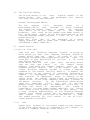
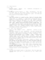
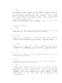
"DAYNER"
USER MANUAL
Table of Contents
Introduction: Product Overview
Page
1
1
1
1.0
The "Chassis" System
1.1 The Desktop Chassis
1. 2 The Studio Chassis
2.0
The
2 .1
2.2
2.3
2 .4
2.5
2.6
2.7
2.8
2.9
2 .10
3.0
The "In-line" Module
3 .1 Output section
3 . 2 Input section
3 . 3 Equalizer section
3 . 4 Aux send section
3 . 5 Monitor section
3 . 6 Assign section
3 .7 Channel section
3 .8 Input/output jacks
6
6
7
8
9
10
11
11
12
4.0
The "Split" Module
4 .1 Output section
4 . 2 Input section
4 . 3 Equalizer section
4 .4 Aux send section
4 . 5 Assign section
4 . 6 Channel section
4 . 7 Input/output jacks
13
13
14
15
16
17
18
19
5.0
The "Optional" Modules
5.1 The "Tape/Effects Return module
5 . 2 The "Patchbay" module
5 . 3 The "Blank" module
20
20
20
20
6.0
The "Operation" (How to use)
21
7.0
Installation; Electrical
27
"Master" Module
LED indicators
Oscillator
Talkback volume/talkback mic
Aux masters
PFL mode
Master monitor section
Talkback switch
Solo/afl LED indicator
Phones
Master inputs/outputs
2
2
2
2
2
3
3
4
4
4
4
8 . 0 Installation; Audio
28
9.0
33
Trouble Shooting
10 . 0 Specifications
34
1
D&R Dayner Series
Recording Console
1.0
INTRODUCTION
1.1
PRODUCT OVERVIEW
The D&R DAYNER Series console is extremely compact, user
friendly, and incorporates innovative ideas to simplify
multitrack recording. Utilizing five different frames, (21,
31, 42, 59, and 84), five types of modules to choose from,
and a
comprehensive master
module (which will mount
anywhere in the chassis), you can customize the Dayner
Series to fit your system needs. One of the more popular
features of this series is the "Floating Subgroup System"
which allows you to create subgroups where you need them
as opposed to a fixed location. This feature also allows the
user to have as many (summed) outputs as desired, which
are limited only by the amount of input modules in a given
frame. With three main types of input modules available,
features such as: "fader reverse" and "split Eq" (on the
In-line modules only) and the Split module (which can be
used as a regular mic/line module or a subgroup module) are
just some of the new innovative ideas that D&R uses to
approach the conflicting needs an engineer faces during the
recording or mixing session.
The basic idea behind the DAYNER is to have an input for
every signal source, be it a microphone, a line level
signal, tape input/output or effect return. Although the
DAYNER can be used . for sound reinforcement or broadcast,
this manual will deal mainly with using the DAYNER in
multitrack recording applications. However, we will make
remarks throughout this manual where sound reinforcement and
broadcast applications apply. The DAYNER has many features
that make "live" or broadcast mixing worry free. To become
familiar with all the facilities of the DAYNER, we advise
you to read this manual very carefully and thoroughly. It
will provide you with important information about
the
installation, operation, and servicing of your DAYNER.
Thank you for selecting the D&R DAYNER SERIES. The Dayner is
the result of a console designed on the cutting edge of
technology.
D&R Electronica b.v.
Rijnkade 15B
1382 GS Weesp
The Netherlands
2
The Dayner Chassis
1.0 The "Chassis" System
The D&R
Design Team
had a real challenge when the
requirement was to design a console that would allow the
master module or any modules to be mounted in any open
space in the frame in any order. On top of all that,
they were asked to make the module connector system and
meters follow any possible combination. In designing the
Dayner Series, they exceeded
not only D&R's high
standards, but designed
the first totally modular
console chassis. The Dayner Chassis System allows you to
custom order your Dayner configured to your needs. If
you want the master section (or modular patchbay) in the
middle, right end, or left end, no problem. This also
allows you to mix and match the three types of input
modules and optional modules to fit your particular
situation.
1.1
The Desktop Chassis
The Dayner Series Desktop model is available in five
different chassis sizes; 21,
31, 42, 59, and 84
position. The frame is fabricated heavy steel with
welded seems. Each chassis includes the master section,
internal cable harness, and rackmount power supply (two
supplies come with the 59 and 84 chassis'). In
configuring any Dayner console, remember to deduct three
module spaces for the master section.
1.2
The Studio Chassis
When D&R first designed the Dayner Series (in 1985), it
was only available in the desktop version. Although many
24 and 32 track digital and analog studios use the
desktop model, D&R still had constant requests from
major studio owners to build a cabinet with legs or
pedestal base. Many studio engineers and their clients
like the sound and functions of the Dayner, however,
they wanted the look of a more expensive console.
Through the joint efforts of D&R USA and the D&R factory
design team, the Dayner Studio chassis was introduced in
1987. The Studio chassis is available in a 42, 59, or 84
position chassis. Included in this version is deeper,
thicker wood ends, the "sleek looking" swept back legs,
deeper, thicker armrest, cable trough, and backdoors to
conceal the wiring. The studio chassis is shipped with
the legs disassembled. Twenty minutes is required for
assembly.
3
Ml
DAYNER
- 18;
+ IB;
'[
I"
level
o o
•)<J:
a
io
O
IO
O -:»o
ma5tG r'uutput
1 o u t p u t s £?
Q
10
O
D
a
a
4
I
I
5
e
I
I
7
B
I
I
o o
TO
Q
a
3
o o
10
Q
O
O
2-1 ra ck B £- track C
I
I
O
O
O-O
2-t.raukA C R M - a l t
I
CRM
o o
10
O
I
0^~0
O
power
O
a•'
Q
o
10
OF o ^
•
10
^ ^ ^ ^ ^
i
1
2
3
4
c
O OH
• * * au<a
O
1D
• * •
O channel
TO t o
D*• •"
o
s
-J
3-trackB
n
n—
4
2x C R M output:
headphone
3x 2 t r a c k ret.
balanced X L R
2.0
Master Module
The Dayner master module contains all the electronics for
the summing of
the
left/right signals, aux master
section, a single frequency oscillator, talkback section,
subgroup amps, 3 tape returns as well as the Control Room
Monitor section. The width of this module is 90mm (3 times
the width of a channel module).
2.1. a. +18v
b. -18v
c. +48v
These three LEDs indicate that power is present on the
voltage rails throughout the Dayner chassis. +/- 18 Volt
for the electronics and +48
Volt phantom powering for
condenser microphones and direct injection boxes.
2.2. a.b. Oscillator
The DAYNER has a single frequency, low distortion, phase
shift type oscillator which produces a lKhz sine wave tone.
The level can be adjusted via the (2.b) control.
Switch (2.a) routes the oscillator
signal
to all mix
busses in the
DAYNER.
To provide the channel output
with the sine-wave, it is necessary to activate one of
the from sub switches on the output section of each
module. Use the trim control for
fine
adjustment
of
each
channel. Because the meters on the Dayner Series
are all peak ballistics, they should read -10 on the
channel output meters when the (2.b) control is wide open.
If you measured the +4 output of the channel or master,
it would
read
1.23
volts on an AC volt meter. The LED
meter is actually reading -6 on the scale, however, there is
no LEDs between -3 and -10. All other outputs, such as aux
outputs and master left/right outputs only receive the tone
if their associated master controls are opened.
Another function of the tone switch is to DIM the control
room monitor speakers by 20db.
2.3
talkback volume
The built in electret microphone can be adjusted in level
and is permanently routed to the Aux 1 and 2 busses
optional to Aux 3 thru 8). To avoid feedback the talkback
(switch 7 on drawing) also dims the C.R.M. output by 20dB.
2.4
aux masters 1 thru 8
These 8 controls are the aux master
levels
to
the 8
aux outputs. Every output
has
an associated A.F.L.
(after fade listen) switch to solo and meter the signal.
5
5
channel to pfl mode
The Dayner Series has
a
dual
function
solo system.
This switch activates
the pfl (pre fade listen) mode
to all channels allowing you to hear
the
input
signal
before he fader, mute
switch, and channel insert when
you push a channel solo or monitor solo switch. When you
listen under these conditions, the signal in the pfl mode
will be in mono (both speakers). With this switch in the
up position, the solo system allows
you
to listen to
the signal after the channel insert (solo in place), fader,
and panpot in stereo. In this condition you could solo
signals
after
you insert signal processing such as
limiter/-compressors or equalizers.
Example: When monitoring the solo system in stereo, you
could solo all the drum tracks and
hear them where they
are in the stereo image and at the same volume they are
in the stereo mix.
6
Monitor Section
This section of the Dayner lets you monitor individual
channels in mono or stereo, the master mix, the aux outputs
and playback three external stereo machines.
6. a.b.
2 track a and b
These
two
switches
allow
you
to
stereo machine a or b.
These
could
machines,
stereo mastering machines,
cassette recorders.
playback either
be
for
DAT
CD players, or
6. c. mono
Switch 6.c allows you to listen to your control room
speakers in mono and do a mono compatibility check of
the stereo signal. This
is
a
good
feature
for
checking
for phase cancellations. Summing the left/right
monitor channels will not affect the main stereo output.
6. d. 2 track c
Switch 6.d will allow you to playback a third two track
machine (DAT, CD player, cassette, etc).
6. e. CRM (Control Room Monitor)
The CRM control adjusts
the
outgoing
signal
to the
main monitoring amplifier. This signal can be either the
output of the solo system, the master left/right outputs or
an external (2 track) signal. The nominal outgoing level is
+4dBu.
6
2.6. f, alt
This switch allows you to switch an alternative (near field)
monitor speaker amplifiers.
2.7
talkback
This is
a
conventional
talkback switch which routes
the talkback to the Aux 1 and 2 busses. At the same time it
dims the C.R.M. output by
20dB
to
avoid feedback. An
electronic delay in the
activating
of
the
electret
microphone avoids mechanical noise when the
talkback
switch is pushed. Routing to aux 3-8 is optional.
2.8
solo/afl LED
If anywhere in the
console a
solo/a.f.1. button is
activated, this LED lights.
You
hear the selected
signal instead of what's being feed to the C.R.M.
2.9. a.b. phones
This section has
a
high
powered stereo headphone
amplifier with volume control and stereo phone jack. You
hear the crm signal on your headphones. It is suitable for
600 Ohms head phones.
2.10 Master Inputs/Outputs
This section of the DAYNER provides all the connections
with the external equipment, such
as signal processors,
headphone amps, power amps, and power supply.
2.10.a.b.
stereo master outputs
These
two
XLR
connectors
are the master
outputs.
Electronic balanced +4dBu. -lOdBv by jumpersetting.
2.11.a.b.c.d.
mix
auxiliary outputs
These 8 outputs are from the aux masters
and allow
connection to the headphone monitor (cue) amps and/or
signal processors. A mating 1/4" mono plug can be used.
2.12.a.
two track B
This jack is a stereo input
for returning stereo machine
B, which could be a DAT machine, CD player, or cassette
recorder for playback (switchable on master section). The
mating plug is a 1/4" stereo plug, tip is left, ring is
right, and sleeve is ground for both. Level setting with
internal jumper +4dBu or -lOdBv.
7
2.12.b.
two track C
This jack is a stereo input for returning stereo machine
C, which could be a DAT machine, CD player, or cassette
recorder for playback (switchable on master section). The
mating plug is a 1/4" stereo plug, tip is left, ring is
right, and sleeve is ground for both. Level setting with
internal jumper +4dBu or -lOdBv.
2.13.a.b.
master inserts
These 2 jacks are
right inserts. The
provided to insert
stereo devices into
master faders.
devoted
to
the
master
left and
level is OdBu. These 2 inserts are
limiters, aural exciters, or other
the stereo mix immediately before the
2.14.a. 2 track A
This jack is a stereo input
for returning stereo machine
A, which could be a
stereo
mastering machine, DAT
machine, CD player, or cassette
recorder for playback
(switchable on master section). The mating plug is a 1/4"
stereo plug, tip is left, ring is right, and sleeve is
ground for both. Level only +4dBu for professional master
machines.
2.14.b. alt
This alternate monitor output
is
for
sending
the
stereo signal out to a separate power amp for small
speakers such as Auratones. The alt switch on the master
will switch between the small and large speakers (outputs to
two stereo amps).
Nominal level is +4dBu. Tip is left, ring is right, and
sleeve is ground for both.
2.15 C.R.M.
This is the stereo output of the Control Room Monitor and
is used to drive the inputs of a power amp for your control
room monitor speakers. Nominal level is +4dBu. Tip is
left, ring is right, and sleeve is ground for both. Do
not plug 8 ohm headphones into this output. You may use
only those with a 600 ohm impedance or above.
2.16 power
The DAYNER is
powered
from
an
external
heavy duty
power supply. The supply voltages of +/- 18 Volt and +48
Volt are fused on the front panel of the
power supply.
The master section
has three LED indicators when the
voltages are present. The power supply is connected to the
console via a 5 pin XLR type connector. This connector is
only used with 21, 31 or 42 frame sizes. The 59 and 84
frames have power connectors mounted on the backside of the
frame.
2.17
Ground post
This is the main ground post for the entire console.
8
from
,M •« P-J
-?Pl
—•
-•
o
to
BO
Ik
£5-
U,.|T]J
9
3.0
The "In-line" Module
The In-line module is our
most
popular module in the
Dayner Series.
The
next
few paragraphs will explain
its many functions and features.
Channel LED Bargraph Meters
The six
segment
L.E.D.
bargraph
meter
is
a
peak-reading device
that
conforms
to world standards
for attack and release times. It reads
the
outgoing
level which is on the output jack of
the
channel
backplate. This could be the channel post-fader signal or
the group output signal (if you have depressed one of the
floating subgroup output switches 1 a-b-c or d, see 3.1
Output Section).
Note: The
first
LED
in
the
bargraph
is a power
supply indicator. When it reads -6dB (-10dB ledbars) it is
callibrated (+4dBu/-10dBu out).
3.1
Output Section
3.1.a.b.c.d. from subs
Used with the "Floating Subgroup
System" to assign to
which output you want your subgroup assigned. Module #1
output would feed the
input
of track #1 on your
multitrack and module #48 output would feed the
input
of
track #48 on your multitrack (if you have
a
48 track
Sony Digital machine).
Black switch caps are
odd
(pan
left) and white switch
caps are even (pan right)
on
the
channel assign
panpots, (just above the channel faders). Refer to the
"channel assign" section. The In-line module
uses our
unique "Floating Subgroup System" to create a subgroup
anywhere in the console and only where it is needed. The
upper section of the channel is completely dedicated to
outputs
or subgrouping. When one of the a-b-c-d (from
sub) switches
is depressed, (refer to drawing on the
facing page) the channel output signal is coupled to the
output of one of the eight subgroup buss amps (located in
the master section).
In
the odd modules (black switch
caps) are
subgroups
1-3-5-7
only
and
in
the even
modules (white switch caps) are subgroups 2-4-6-8 only. If
no "from sub" switch is
depressed,
the
output is
normalled to the post fader channel amplifier (ie. direct
out). Refer to the "routing" section of this manual for
a more in-depth understanding of the "Floating Subgroup
System". Each channel output has an adjustable
output
trim control
(1-e) with a gain of 6dB and cut of 15dB.
The normal position for this control is set at 12:00.
Center detend is provided.
3.1.e.
trim
Output trim (volume) of the direct output on that channel.
If any "from subs" switch is activated on this channel, it
would be a (summed) subgroup volume control.
10
3.2
Input Section
3. 2.a. +48v
Phantom power
switch
direct injection boxes.
for
condenser
microphones
or
3.2.b. pad
Using this switch inserts a
20dB
attenuation
into the
mic input amp. If the signal source is too loud, you use
this in conjunction with the mic/line gain
to allow you
more control on the channel faders.
3.2.c. phase
Use this switch to reverse the
phase of any mic input
coming from a mic or signal that may be out of phase with
other mics or signals. A good way to check for "out of
phase" is to push the mono switch on the master section
and listen closely to the mix.
If you hear " something
that sounds strange or completely missing in your mix,
push the phase switch on those channels suspected. If
the sound returns or sounds better, that channel was out
of phase with the others. You can have an acoustical phase
cancellation as well when using multiple mics on the
same
signal
such
as
drums, vocals, horns, strings, etc.
Physically moving mics inches will in most cases correct
an acoustical phase cancellation.
3.2.d. gain (very important)
This is the single
most
important
control on your
console.
When this control is set properly,
you can achieve the
very best signal to noise ratio and get the most headroom
needed for high quality recordings. After plugging
in a
mic, push the "channel to pfl mode" switch on the master
section. Now push the solo
switch
just
above
the
channel fader on the channel you're setting,
(with the
channel fader off). Turn the gain control clockwise until
you see a "0" output level on the master meters. Now slide
up the channel fader to "0".
Remember, if the signal source gets louder or softer, you
may have to go back and check this setting. The volume can
also change if you boost or cut
in the equalizer section.
Be sure the signal being miked stays the same volume when
you start recording, or you'll need to go back and do all
this again.
IT'S IMPERATIVE TO DO
THIS WITH EVERY MICROPHONE INPUT
OR LINE INPUT TO ACHIEVE THE HIGH QUALITY AND SPECS D&R
PRODUCTS ARE KNOWN FOR.
NOTE: Do not use the output meter on the same module for
setting levels. It will read higher.
3.2.e. line
Switches the channel input to line level. The line input has
its own input jack and is controlled by the (dual) Gain
control.
11
2. f. remix
Switches the tape
return
from the monitor section to
the channel input (controlled by channel
fader)
and at
the same time switches the mic or line input into the
monitor section controlled by the
monitor
pot.
This
gives you double the inputs in mix. This is effective
for effect returns or virtual tracks (live tracks,
ie.
midi synchronised tracks).
Refer to paragraph 3.3.f
(split
EQ) for EQ in the
monitor section of the in-line module.
3
Equalizer Section
3.a.
high
Boost or cut 16dB at 12,000Hz shelving (boost
same amount at all frequencies above 12,000Hz).
3.b.
or cut the
hf mid
Boost or cut 16dB bell curve sweepable from 500Hz to
10,000Hz with a width of 1.5 octaves.
The top control is
boost or cut and bottom control is the frequency sweep.
3.c.
If mid
Boost or cut 16dB bell
curve
sweepable from 50Hz to
1,000Hz with a bandwidth of 1.5 octaves.
The top control
is boost or cut and bottom control is the frequency sweep.
3.d.
low
Boost or cut 16dB at
60
same amount below 60Hz).
Hz
shelving (boost or cut the
3 . e . eq
Switches the equalizer in or out of the circuit allowing a
comparison of with or without EQ.
3.f.
split
Pushing this switch allows
you
to
actually
split
the equalizer into two sections. The high and low shelving
bands will switch to the monitor section and the two
sweepable mids will switch
to
the
channel fader,
allowing you to have equalization on both inputs, on the
same module, at the same time. The EQ switch must be
activated also.
12
3.4 Aux Send Section
3.4.a.
aux 1-2
The top control is aux send
1 and bottom control is aux
send 2. This pair of aux sends are most commonly used
for cue sends (stereo headphones), top
control being
left or cue 1 and bottom control being right or cue 2.
Aux sends 1 and 2 can be used as effect sends in the mixing
session.
3.4.b. post:
This switch allows you to choose
from where aux 1 and 2
get their signal. In the up
position (pre) the signal
comes from before the fader and in the down position
(post) the signal comes from after the fader. It's a good
idea to use the pre position when using aux 1 and 2 for cue
or headphones so when changing the monitor
levels
you
won't affect the headphone mix.
3.4.C.
aux 3-4:
Aux 3-4 can be used as effect sends or as two separate
independent mixes or a stereo mix for headphones. Standard
from the factory, these aux sends get their signal from the
monitor section, however, you can switch them to the channel
by the "aux to channel" switch (3.5.a.) and you can change
permanently from the monitor section to the prefade channel
or the postfade channel with solderless jumpers on the
circuit board.
3.4.d. aux 5-6:
Aux 5-6 is identical to
to the aux 7-8 busses.
3.4.e.
aux
3-4, only they are switchable
7-8
When
you
activate
this
switch,
you move the
concentric aux 5/6 controls (double controls) from feeding
aux busses 5 & 6 or aux busses 7 & 8.
13
5
Monitor Section
5.a.
aux to channel
This switch will allow all aux sends to get their signal
from the channel fader, except those who are permanently set
with the jumper settings.
5.b.
tape
This switch will
choose
from where the monitor gets
it's signal. In the up position
(source), the channel
fader feeds the monitor and in the down position (tape),
the tape return feeds the monitor.
5.c.
pan
This control will pan the
signal
in
section between the left/right stereo image
mix buss.
5.d.
mute
This switch will
module.
5.e.
the
monitor
on the stereo
turn
the
monitor
section
off
on that
solo
This switch will allow you
to hear only the signal in
the monitor section. Depending upon what position the
"channel to pfl mode" switch (located in
the master
section) is in, you may hear the signal mono pre fade
(monitor level) listen or stereo in place following the
panpot.
5.f.
mon (monitor)
This controls the volume
in
the monitor
section of
that channel. It gets it's signal
depending on what
position the tape switch is in. In
the
up position
(source), the channel fader feeds the monitor and in the
down position (tape), the tape return feeds the monitor.
5.g.
fdr/rev (fader reverse)
This switch will allow
you
to
swap places with the
channel fader and the monitor pot.
In the down position,
the channel fader
controls
the
monitor
section and
the monitor pot controls the output of the channel to
the direct out or summed output to the multitrack. Now
those producers can play with the faders without affecting
the signal going to the tape machine. This feature is
also useful when you need fader control on something in the
monitor section at the same time fader control was not
needed on what is in the channel.
14
3.6
Assign Section
3.6.a.
channel pan
This control allows you to place the signal anywhere in
the stereo image, which feeds
the mix busses
or the
subgroups buss assigns.
3.6.b.
1-2
This switch allows you to assign to subgroups 1 & 2.
3.6.C.
3-4
This switch allows you to assign to subgroups 3 & 4.
3.6.d. 5-6
This switch allows you to assign to subgroups 5 & 6.
3.6.e.
7-8
This switch allows you to assign to subgroups 7 & 8.
3 . 6.f. mix
Assigns the channel to the stereo mix busses.
3.7
Channel Section
3.7.a.
mute
Breaks the signal flow on the entire channel.
3.7.b.
solo
Allows you to hear the
channel only on your monitor
speakers in mono prefade listen
(pfl)
mode
or in place
stereo mode, depending on what position
the channel to
pfl mode switch
(located on the master section) is in.
15
3.8
Input/Output Jacks
3.8.a.
mic input
This is the balanced XLR
input
for
condenser
or
dynamic microphones, This input can become a balanced
line input if desired. Contact the D&R Technical Support
Department or details.
3.8.b.
line input
LINE INPUT is used
for
plugging in the outputs of
digital reverbs, digital delays,
drum machines, samplers,
keyboards, CD players, cassette machines or any other
line level outputs.
3.8.c.
channel insert
CHANNEL INSERT is used to
patch
(prefade)
channel,
any
signal
processing
equipment
compressor/limiters, equalizers, etc. Level OdBu.
3.8.d.
into the
such as
tape send
TAPE SEND is used as a
summed output of any channel. It
will appear as a direct out of the channel until you push
one of the "from subs" switches. At that time, you send the
subgroup buss
that is being sent
via the subgroup
assignment switches (just below the channel panpots)
to
the
input
of your multitrack tape machine. Refer to
Assign section 4.5 and "Subgrouping". Levels: Tip = -lOdBV
Ring = +4dBu.
3.8.e.
tape return
TAPE
RETURN
is
used
for
plugging the output of
your multitrack tape machine or the outputs of any effects
such as digital delays, digital reverbs, aural exciters,
etc. this track or effect will now appear in the monitor
section if the tape switch is down. If you push down the
remix switch, this track or effect will
now
appear in
the
channel
and be controlled by the channel fader. The
microphone input or line input will now
appear
in the
monitor
section of
the same module. This will be
controlled by the monitor pot and manned onto the stereo
mix buss. This allows you to mix two signals completely
independent of each other on the same module.
Levels: Tip = -lOdBV, Ring = +4dBu.
16
trom
*uba
i/e
D
tdmixL—l
pad
.D-
*—no
10
!«•/ I
gmup I
I
I
\ x hl9h
Ik
10-
IOO
1k
•
•
-10
£fer
p—d-1
£^
a
1D
—«-Q 1
Q^
a
ID
BUXB-|~|
o
10
L
R
Lmb
1
CH
17
CHAN
CHAN
r«t.
Send
C2)
M D
DQVNER-PQTCH
®
«»rth
(•)
earth
Example
of
patch
PPNEL
connect Ions
Opt L o n !
non- I n t e r r u p t .
send-j acki
c o n n e c t only
t h e t Lp
1
2
3
s
6
7
8
9
10
11
12
13
1S15
16
ring
tip
ring
tip
ring
tip
ring
tip
ring
tip
ring
tip
ring
tip
ring
tip
ring
tip
ring
tip
ring
tip
ring
tip
ring
tip
ring
tip
ring
tip
ring
tip
1
2
3
"r
G
6
7
8
9
18
11
12
13
1"r
15
16
Fing
tip
ring
tip
ring
tip
ring
tip
r ng
t P
r
t
r
t
r
t
r
t
r
t
r
t
r
t
r
t
r
t
r
t
r
ng
P
ng
P
ng
P
ng
P
ng
P
ng
P
n
9
P
n
9
P
n
9
P
ng
P
n
9 INTERNAL
MIRINB
OF
JRCKS
t p
CHQN Send
CHAN r e t u r n
4.0
The "Split" Module
The "Split" module
is
not
unlike most
split format
input modules with the exception
of
a
couple of
features. As you read this section, these features will
become prevalent.
Channel LED Bargraph Meters
The six
segment
L.E.D.
bargraph
meter
is
a
peak-reading device that conforms
to
world
standards
for
attack and release times. It reads the outgoing
level which is on the output jack of
the
channel
backplate. This could be the channel post-fader signal or
the group output signal (if you have depressed one of the
floating subgroup output switches 1 a-b-c or d, see 4.1
Output Section).
Note: The first LED
in
the
bargraph
is
a
power
supply indicator. When the channel output is +4dBu/-10dBV,
the ledbar reads -6dB (-10dB led burns).
4.1
Output Section
4.1.a.b.c.d.
from subs
The Split Module uses
our
unique "Floating Subgroup
System" to create a subgroup anywhere in the console and
only where it is needed. This is a simple
and efficient
way of using subgroups. The upper
section
of the
channel is completely dedicated to subgrouping. When one of
the a-b-c-d (from sub) switches is depressed, (refer to
drawing on facing page) the channel output signal is
coupled to
the output of one of the eight subgroup buss
amps
(located
on
one
of
the circuit boards in the
master section). In the odd modules (black switch caps)
are subgroups 1-3-5-7
only
and
in
the even modules
(white switch caps)
are 2-4-6-8 only. If no "from sub"
switch is depressed, the output is normalled to the post
fader channel amplifier
(ie. direct out). Refer to
the "assign" section 4.5 of this
manual
for
a
more
in-depth understanding of the "Floating Subgroup System".
4.I.e.
trim
Each channel output
has
an
adjustable output trim
control (1-e) with a gain of 6dB and cut of 15dB. The
normal position for this control is set at 12:00.
4.1.f. sub to mix
The "sub to mix" switch (1-f) sends the channel output
signal to the stereo mix buss (odd channels to
the left
and even channels to the right). This
could be the
subgroup signal or the channel output. CAUTION:
There are
two ways of routing signals to the stereo mix busses;
from the output section (sub to mix) (on Split modules
only) or assigning the channel to the mix (switch 5-f). Be
careful not to choose both, for
it will increase the output gain by approximately 6 dB.
18
4.2
Input Section
The channel can operate in
either
microphone or line
input mode.
The
microphone
input
is
a electronic
balanced, transformerless design. The input-impedance is
greater than 2 Kohms, which will not cause any loading
effects on todays studio microphones. The line
input;
which
can
be used or effect returns, digital recorder
playback, CD players, or any line level device, has an
input
impedance
greater than 0 Kohms, which is high
enough
to
interface with
all available peripheral
equipment.
4.2.a. +48v
The +48
Volt
switch
routes
power to condenser
microphones, Direct injection boxes,
or any
device
requiring "phantom power". When using dynamic microphones
or any other equipment not requiring phantom power, the
phantom power switch should be in the off or up position.
4.2.b. pad
Pushing the pad switch inserts 20dB of attenuation into the
input of the microphone amp. This could be necessary when
modern condenser microphones are used in close proximity to
musical instruments.
Even direct
injection boxes are
capable of providing high level signals. The pad switch
also raises the input impedance, providing a balanced line
input when needed.
NOTE: With special orders, we can increase the pad to 30dB
and the impedance as well, to
provide for balanced,
switched mic/line inputs.
4.2.c.
gain
The microphone input gain can be varied between 20dB and
55dB of gain. The 20dB pad increases the control range to
55dB. Thee line input gain
can be varied between -20dB
and +20db. One control varies both sets of electronics.
Both the
mic and
line inputs have their own input
connectors. The mic input is balanced on an XLR type
connector. The line input on a mono jack connector. The
line/group switch must be in the down position to activate
the line input thus turning off the microphone input.
4.2.d. phase
The phase reverse switch reverses the wiring of the mic
input only. In most cases it is the mic signal that's out
of phase with another microphone.
19
4.2.e.
line/group
The line input is activated by pushing the line/group
switch. The line input
can
also
be
used
when the
entire module (fader, full EQ,
and
all
aux send
busses) is required to return the output of a "Floating
Subgroup". An external patch must be made between the
channel output and the line input of the same module.
Refer to the "Subgrouping" section. The cable for this is
special made. CAUTION: DO NOT USE A NORMAL PATCH CORD FOR
THIS PATCH. Refer to the Section 4.7 for details.
4.3
Equalizer Section
The Dayner equalizer stands
out
by
virtue of its
effective design. Utilizing
a
proven
(partly passive)
circuit only found on
"high
cost"
consoles,
it has
four sections to control the entire audio spectrum.
4.3.a.
high
16dB of boost or cut is
available
at 12kHz, with a
shelving curve, which means; when the desired amount of
boost or cut is reached the curve
shelves
from
that
frequency on (everything above 12kHz is the same).
4.3.b.
freq (frequency for mid 1)
This control selects the center-frequency of the mid 1
section. It sweeps from 1kHz to 11kHz.
4.3.C.
mid 1
This control has 16dB of
boost or cut with a "bell"
shaped curve. Having reached your maximum or minimum amount
of boost or cut (control 3.c) of the selected frequency
(control 3.b), the amplitude response returns to zero on
either side of that selected frequency. The bandwidth of
the bell curve is fixed at 1.5 octaves.
4.3.d.
freq (frequency for mid 2)
This control selects the centre-frequency of the mid 2 band.
It sweeps from 80Hz to 1kHz.
4.3.e.
mid 2
This control has 16dB of boost or cut with a "bell" shaped
curve. Having reached your maximum or minimum amount of
boost or cut (control 3.e) of the selected frequency
(control 3.d), the amplitude response returns to zero on
either side of that selected frequency. The bandwidth of
the bell curve is fixed at 1.5 octaves. This controls does
the same as the mid 1 control (3.c) but now for the selected
frequencies of the mid 2 frequency sweep.
20
3 . f. low
The low control has a shelving characteristic just like the
high (3.a) control. 16dB of boost or cut is available at
60Hz. (Boost or cut of all frequencies below 60Hz).
NOTE: The eq. section can be easily modified to increase or
decrease the frequency range of each band to best suit your
individual needs.
Contact
the
D&R
Customer Support
Department for details.
3.g.
eq on
The equalizer section can be switched in
comparing equalized or unequalized signals.
4
or
out
for
Auxiliary Section
There are 5 aux send controls and 8 aux busses. The
following
paragraphs
will
describe the use of this
section. The 8 master gain controls (for all 8 aux busses)
are located in the master section.
4.a.b.c.
aux 1,2, and post
Auxiliary sends 1 and 2 are normally pre-fader but can be
switched post-fader if desired. They are intended to be used
as stereo headphone sends during the recording session and
effect sends in the remix or virtual tracking session.
These aux sends are wired post EQ, post insertion point,
and post channel mute. In a live sound situation, these aux
sends could be used as stage monitor feeds.
4.d.e.
aux 3/4
Aux send 3 is normally wired post-fader on the P.CB. but
can be changed easily by rerouting the associated zero ohm
resistors. This option is available from D&R, however, if
you choose to perform this modification, please contact the
D&R Customer Support Department for assistance. The output
of Aux send 3 can be routed to aux send buss 4 by pushing
the associated push-button (4 e). Aux buss 4 is also
post-fader wired.
4.f.g.h.i.
aux 5-8
Aux sends 5 through 8 are exactly the same as Aux send 3
and 4 in wiring and possibilities. All normally post-fader
but easily changeable to pre-fader.
21
4.5
Assign Section
The channel input signal can be routed to any or all of the
8 subgroup busses as well as the stereo mix busses byselecting the relevant routing push-buttons.
4.5.a. pan
This control (with a 4.5 dB loss at its center point) pans
the signal between the odd and even subgroup busses as well
as the left and right master busses, when selected.
4.5.b.c.d.e.f.
(routing the input)
Selection of any routing button assigns the channel signal
via the pan-pot to a pair of output groups, or to the
stereo mix. EXAMPLE: To assign a channel to buss 1, you
would press the 1-2
(5.b) switch and turn the panpot
fully counter-clockwise or to assign to buss 2 you would
pan fully clockwise. Now that you know how to assign to the
subgroup busses, we can now move on to the exciting world of
"Floating Subgroups".
Subgrouping
Due to the innovative D&R Technical Design Team, subgrouping
may never be the same. Enter the "Floating Subgroup System".
The idea behind it is having subgroup amplifiers only where
you need them. This means; there are no summing amps
preceding every channel output. But with the "Floating
Subgroup System" it is still possible to subgroup signals
before they are sent to the channel outputs. The DAYNER has
8 subgroup amplifiers which are physically located on one
of the printed circuit boards in the master section. All
signals coming from the channel routing 1 thru 8 (5.b thru
f) are mixed in the subgroup amps and sent back via 8 busses
to the output section (from subs) of each channel. With the
routing buttons, you send signals to the subamps and with
the "from sub" buttons you receive signals from the subamps.
In this way you can select which channel output to receive
the subgroup signals. You can even send the subgroup signals
to more than one output. To record a stereo image, it was
necessary to give the
odd
numbered
channel modules
(1-3-5-7-9-11 etc.) the output from subamps 1-3-5-7 only,
and give the even channel modules (2-4-6-8-10
etc.)
subgroup outputs 2-4-6-8 only. Stereo subgroups must be made
in pairs of 2. The Trim control can adjust balance while the
sub to mix routing push button can route this whole subgroup
signal to the master left/right busses. NOTE: Odd numbered
channels to the left master and even numbered channels to
the right master outputs.
22
EXAMPLE: Let's say you have a Dayner with 48 input modules
and a 48 track machine. The kick drum is on module 1 and
the snare is on module 2. You would not assign these inputs
because they will feed directly to tracks 1 and 2 on the
Recorder.
Now, input modules 3,4,5, and 6, each have toms and you want
to record a stereo mix of them on tracks 3 and 4. No
problem! Use the assign switches 1-2 on each of those inputs
(3 thru 6) and pan
each input where you would like it
placed in the stereo image. Now go to the output section of
modules 3 and 4 and press the 1-2 "from subs" switches. The
output jacks on the rear of modules 3 and 4 are feeding
tracks 3 and 4 on the Recorder, now you would go to the
monitor section of tracks 1-2-3-4 on your Dayner (monitor
section of In-line module or Tape/Effects Return module)
and track one will be kick, track .two will be snare, and
tracks three and four will be a stereo mix of all the toms.
If for some odd reason, you may want to send all those toms
to tracks 47 and 48 at the same time you are sending them to
tracks 3 and 4, no problem! Just go to the output section
of modules 47 and 48 and press the "from subs" 1-2 switches.
If now you are really confused, just call our Customer
Support Department for assistance.
Channel Section
a. mute
The channel mute switch (with a green LED indicator) mutes
the entire channel as well as all auxiliary sends, with the
exception of the signal to the insert jack. The mute switch
does not affect the p.f.l. signal coming from the channel
(if the "channel to pfl mode" is activated in the master
section).
b.
solo
The Dayner has a dual function solo system; pre fade listen
or in place stereo. It is possible to solo; before the
fader, after the insert jack, and before the mute switch if
you press the "channel to pfl mode" switch (located on the
master section) before activating any solo or pfl switch.
For "In Place Stereo" solo, the "channel to pfl mode"
switch must be in the up position. This would be a solo
after the insert point, fader, and pan pot which is of
course affected by the channel mute switch. A solo LED
indicator in the master section, together with the channel
solo LED indicator, denotes a channel solo switch is
activated.
Channel Fader (not drawn)
The channel fader has a slide length of 100mm and is
designed to give an exceptionally smooth feel in operation.
23
4.7
Input/Output Jacks
4.7.a.
mic input
This is the balanced XLR input for condenser or dynamic
microphones. This input can become a balanced line input if
desired. Contact the D&R Technical Support Department for
details.
4.7.b. line input
The line input is unbalanced, (balanced is optional). This
input has a sensitivity of -20dB maximum to infinity. The
input impedance (lOKohms) will allow proper interface of
any line outputs of tape recorders or signal processors.
4.7
SPECIAL PATCH CORD:
This cord is for patching out of the channel output (on the
In-line or Split Module) to the line input of the same
module. Line in end: Mono plug, tip + and sleeve ground.
Channel out end: Stereo plug, ring + and sleeve ground. NO
CONNECTION TO THE TIP.
4.7.c.
output
This is the output of the channel. The tip has a nominal
level of -lOdB and the ring +4dB. One of the two output
levels must be left unconnected. The -lOdB signal is for
equipment such as Fostex and the +4dB signal is for
equipment such as Studer. The output signal is after the
channel fader unless you have activated one of the "from
subs" switches which would send a subgroup out that output.
4.7.d.
group insert
The group insert, ring as the send, tip as the return, and
sleeve is the ground for both, will allow you to patch a
signal processor on the subgroup. This insert can also be
used as an effect input with the trimpot as the level pot
and the "sub to mix" switch in the down position (in the
output section) as a way of routing the effect to the
master. Odd channels to the left, even channels to the
right.
4.7.e. chan. insert
The channel insert immediately precedes the channel fader.
Ring is the send, tip is the return and sleeve is the
ground for both. In/out level is OdB.
This concludes the section on the Dayner Series "Split"
module. For installation or hook-up instructions, refer to
the last section of this manual.
24
ft
o
10
poat
QJ
. N ^ ^ X . pan
affect R
0
L
.N^^/.lauel
O
IO
a
•xa
£b
o
post
ip
I ^-
- > * _ _ • . pan
efface' 1 '
o
L
-X..
/ leva I
&
Oi
O
10
poet
I U
ft.
o
L
effect"
. X _ X leval
mute I
11"1
I
|~
&
O
TO
Post
I I
CL
0
L
effect
-*C
O
B
-• level
IO
5.0
"Optional" Modules
5.1
Tape/Effect return module
This module is the most cost effective way of returning tape
tracks, effect returns, drum machines, keyboards, or any
other line level device needed on the mix. Each module has
four returns with a volume control, pan pot, mute switch
solo switch, and two aux sends (switchable pre/post). Each
return feeds the stereo mix busses. All four inputs are
electronically balanced.
5.2
Patchbay module
The Patchbay modules of the DAYNER SERIES contain 16
breakjacks per module. These are wired to a 32 pin Molex
connector on the back of the module. This way of external
wiring allows several different
configurations; simple
in/out in
one jack; inserts in one jack with break
contacts; separate send returns between jack 1 and 2, or
between jack from module 1 and jack 1 from module 2. The
break contact wiring is designed so that the break contacts
are always paralleled, avoiding noise and interruption
after extensive use. The Molex connectors on the back panel
are male. The female mating connectors are supplied with
the patch module and can be wired to meet your specific
needs. The 32 pins are wired to the tip and the ring of
the 16 jacks, while the break contacts of the jacks are
permanently shorted. To use jack 1 as an ordinary channel
insert, connect the tip to the tip of a channel insert and
the ring to the ring of that same channel insert. Now you
have moved the channel insert from the back of the console
to an accessible jack of the patch module. Many configurations can be realized in this way. Before we show you
detailed drawings on some configurations, it is necessary to
know how to ground the patch panel jacks. On the back of
the patch module you will find a ground terminal. This must
be wired externally to the master ground terminal (located
on the back of the master module). Every connection from
the channel to the patch module must be grounded only on
the channel side. Cut the shield on the patch module side
and only connect the wire (or wires) to the tip and/or ring
of the associated patchbay jack. External equipment inputs
must be grounded on the patch ground terminal, lifting the
shield on the input of the external equipment. It is wise
to wire all the external equipment inputs to one patch
panel and the output to an adjacent module. Now connect all
the shields to the output ground of the external equipment.
Always connect one end of the shields only. We will later
explain more about wiring and shielding.
5.3
Blank module
The Dayner Blank module is 30mm wide and is mounted with
two threaded machine screws.
It comes with a blank
backplate. It is possible to order special width (120mm)
Blank or Patchbay modules. Ask a representive from D&R.
25
6.0
"Operation" (How to use)
The DAYNER is designed to be the perfect answer for MIDI Studios
where you do mostly virtual recording or in a morestandard
recording studio with up to 48 tracks of analog or digital
recording. To get more familiar with the DAYNER we shall discuss
the whole recording process and divide it into 5 basic sequences.
Sequence 1 through 4 are for the more conventional recording
studio and sequence 5 is for the MIDI studio.
1
The Session
Recording from microphone or line input onto the multitrack
machine. This could be from one or more channels at the time.
2
The Playback
In this mode you would listen
multitrack machine.
3
to what
has been
recorded on the
The Overdubb
Overdubbing is listening to already recorded tracks and recording
on empty tracks, until all tracks are filled.
4
The Remix
Playing of all recorded tracks together with signal processing
equipment and all that is necessary to create the final mixdown.
5
The MIDI or Virtual Tracking
Programmed keyboards, drum machines, reverbs, effects, Aunt Betty
singing, and who knows what else, all at the same time direct to
your DAT Machine, two track master machine, or cassette deck.
SEQUENCE 1: The Session
RECORD
This is the beginning of a session. All input channels are placed
in the mic mode by leaving the line/group (mic/line on the
in-line module) switch in the up position if the microphone input
is to be used in this channel. Phantom powering is applied if
necessary. The EQ switch should be in the up position unless you
should desire some EQ on that mic. The signal flows through the
fader and is available postfader at the back of the channel on
the output jack which can feed the input to your multitrack
recorder. The LED bargraph reads the outgoing signal.
26
MICROPHONE/LINE GAIN
The amount of gain required may depend on the type of
microphone, the sound pressure level, and the distance
between the sound source and microphone. A 20dB pad can be
inserted where levels are too hot. When the line/group
(line/mic on In-line Module) switch is activated, the same
gain control varies the gain of the separate electronics for
the line input.
MONITORING
The Dayner Series gives you a couple of different ways of
monitoring your multitrack recorder. The most cost effective
way is to use Tape/Effect Return modules to monitor and
playback the tracks. This module has four balanced inputs,
each with a volume control, panpot, two aux sends (for a
stereo headphone mix), a mute switch and a solo switch. The
only drawback with using these modules for monitoring is;
when you need to go into remix, you will need to unplug the
tape return jacks from these modules and plug them into the
standard mic/line modules we call the Split Module (from
split format).
Another way of monitoring your multitrack is with the In-line
module. This format is a little more expensive, however, it
offers many features and
functions
found on consoles
typically costing several times more. The major difference
between this module and the Split module is; it has its own
monitor section on the module which allows the user to have
two usable inputs, both with EQ, both being able to send to
the aux busses, both with their own volume control, panpots,
mutes, and solos, all at the same time.
MULTIPLE MODULES ASSIGNED TO ONE OR TWO TRACKS
When more than one microphone or line signal has to be
recorded on a single track or in stereo on two tracks, a
submix facility will be required. This can be done easily on
the DAYNER by way
of
the internal floating subgroup
amplifiers located on one of the master section printed
circuit boards. Simply route to one of the 8 subgroups by
activating a channel routing switch on as many input modules
as required. Decide on which track you wish to record these
signals and activate the related "from sub" switches on the
output section of that channel. The channel metering will
show the subgroup level which can be overall changed by the
trim controls. To monitor these tracks on the In-Line
modules, the tape switch in the monitor section should be in
the up position to monitor pre-tape (console out) and in the
down position to monitor post-tape). For more detailed
instructions, refer to paragraph section 3.6 a,b,c,d,e, and
f, Assign and Subgrouping.
27
INSERT CHANNEL/GROUP
For high dynamic range types of inputs, a signal processor
such as a compressor/limiter can be inserted in the channel
or even in the group insert (Split Module only), if an entire
group signal needs to be processed.
HEADPHONE(CUE)
During recording it is essential that the talent hear an
independent mix of what the engineer and producer is hearing.
Headphone mixes are
usually
derived
from
pre fader
auxiliaries. In the DAYNER Aux 1 and 2 are ideal for this
purpose. For that reason, the talkback is routed to these
busses. The best way to build a mix for the headphones is to
have the monitor section of the In-line module feed aux
busses 1 and 2.
If
your Dayner is a split format
configuration, (Split Input Modules on the left and Tape
Return Modules on the right),
you would send to the
headphones via the aux send pots on the Tape Return Modules.
EFFECT SENDS
All unused aux sends can be used to send signals to signal
processors such as the D&R "Qverb" 16 Bit Digital Reverb,
effects processors, and digital delays. The Aux sends are
usually post fader to always keep the right balance between
untreated and treated signals.
EFFECTS RETURNS
In todays modern recording or MIDI studios, there is a demand
for many effect returns. For that reason, D&R has designed a
couple of modules to allow the user to customize the effects
returns. The most cost efficient way of returning effects is
with the Tape/Effect Return Module. This module has four
separate balanced returns, each with; a volume control,
panpot, mute switch, solo switch, and two aux sends with a
pre/post switch. The aux sends are used to send the effects
returns out to the headphones when you are using aux 1 and 2
for cue sends. The use of this module is normally with the
less important effects not needing EQ on the returns or not
needing to assign to the "Floating Subgroup System". Each
return on this module feeds the left/right stereo mix buss.
The next way of returning effects is with the Split Input
Module. Returning into the line input jack, you would have
fader level control, panpot, buss assigns with the "Floating
Subgroup System", full EQ, and all eight aux send busses.
Most Dayner owners use this module to return their most
important digital reverbs and effects processors. The Split
Input Module could also be used as a subgroup module allowing
you to subgroup several tracks or virtual inputs in a mix.
28
SEQUENCE 2: The Playback
Multitrack Playback
The Dayner Series gives you a couple of different ways of
monitoring your multitrack recorder. The most cost effective
way is to use Tape/Effect Return modules (each module has
four balanced inputs) to monitor and playback the tracks.
Each input has a volume control, panpot, two aux sends with a
pre/post switch (for a stereo headphone mix), a mute switch
and a solo switch. The only drawback with using these modules
for monitoring is; when you need to go into remix, you will
need to unplug the tape return jacks from these modules and
plug them into the standard mic/line modules we call the
Split Module (the term Split comes from the split format).
Another way of monitoring your multitrack is with the In-line
module. This format is a little more expensive, however, it
offers many features and
functions
found on consoles
typically costing several times more. The major difference
between this module and the Split module is; it has its own
monitor section on the module which allows the user to have
two usable inputs, both with EQ, both being able to send to
the aux busses, both with their own volume control, panpots,
mutes, and solos all at the same time.
SEQUENCE 3: The Overdubb
Multitrack Synchronizing
Overdubbing is the process of building up a recording track
by track while listening to previously recorded tracks. If
your Dayner is a split format configuration (Split Input
Modules for inputs and
Tape/Effect Return Modules for
monitoring the playback), you will need to do most of your
sync switching from the tape machine or remote. If you have
just recorded 10 music tracks and now would like to add the
vocal track, put all 10 tracks on your tape machine in
sel/rep or sync and put the track you wish to overdubb vocal
in input. Now you should hear the tracks along with the
vocal. After you record the vocal, put the vocal track into
sync or sel/rep and listen. If that track was oke, put the
next track into input you wish to record or overdubb. On each
of the returns on the Tape/Effect Return module is two aux
send pots. These are used for sending a stereo headphone mix
to the talent.
If your Dayner has an In-line Module for each track of the
multitrack, you will find it much easier to overdubb. In the
monitor section of the In-line Module, you push all tape
switches down and do all your sync switching from the tape
machine or remote. The headphone mix would be done on the aux
send 1 and 2 busses. Aux 1 and 2 always get their signal from
the monitor section unless you activate the "aux to channel"
switch. That makes all aux busses get their signal from the
channel fader. It is best to activate the pre switch on the
aux 1 and 2 sends of each channel you wish to use for
headphones. By doing that, you can change the monitor level
control on any of the tape monitors without affecting the
headphone mix.
29
SEQUENCE 4: The Remix
Multitrack Mixing
Remix is the process of combining all recorded tracks
together with (keyboards and drum machines for MIDI), signal
processing and sending the mix to a two track master machine,
DAT machine or cassette machine. On the In-Line Module, you
must push the remix switch down. This routes the tape return
to the channel input and routes the mic/line inputs to the
monitor section of the module. At this point, you can use
either a mic or line input into the monitor and it will
automatically feed the stereo mix buss. This gives you two
inputs per module in mixdown. You can activate the EQ Split
switch and have the high and low shelving sections of the
equalizer on the monitor and the two sweepable mids on the
channel. Remember to also activate the EQ switch. Remember to
only activate the remix switch on the channels that need to
be mixed. This allows you to have any extra channels to use
as effect returns or for virtual tracks with full eq and
subgrouping (if desired). All incoming signals can be routed
to the stereo mix busses through the mix switches in the
assignment section of each module. Subgroups can be made as
desired in the same way as during recording. You can have aux
sends 1 thru 4 getting their signal from the monitor section
of the module while aux sends 5 thru 8 get their signal from
the channel fader. If you activate the "aux to channel"
switch, all aux sends get their signal from the channel now.
Solderless jumpers allow you to customize your aux sends.
Call our Customer Support Department for details. Most Dayner
owners use several Split Input Modules for effects returns,
however, you can use the Tape/Effect Return Modules for
returning your effects. A popular configuration for a sixteen
track recording studio would be:
1 DC31 Chassis (holds 28 modules and master).
16 DIM Dayner In-line Modules (for 16 tracks).
8 DSM Dayner Split Modules (for
inputs, mic inputs, or subgroups).
2 DRM Dayner Effect
for effects).
Return Modules
effects
returns,
line
(with 4 returns on each
2 DBM Dayner Blank Modules (can add 2 other modules later).
This configuration would give you a total of 48 inputs in
mix. If you would like to expand to a twenty four track
recording studio, just move up to a larger chassis (the DC42
chassis) and add 8 more In-line Modules and 3 more blank
modules.
30
SEQUENCE 5: The MIDI or Virtual Tracking.
Virtual Tracks: The MIDI Setup
In most MIDI studios you will see an 8 track tape machine
rather than a 16 or 24 track. Most all of the music
production is programmed on a sequencer using MIDI keyboards,
drum machines, or any other MIDI equipment. Because of this,
you only need tape tracks for vocals and some instruments not
adequately reproduced on keyboards today. If you have a
multitrack tape recorder in the MIDI studio, you would use
one of the tracks to print a time code (SMPTE or MIDI code).
This would allow your sequencer to keep your keyboards, drum
machine, and all other MIDI equipment in sync with each
other. Most all MIDI studios purchase the Dayner for the
following reasons;
1.
You can custom order the Dayner to fit your exact
requirements (D&R will load it your way).
2.
Five different chassis sizes (from 18 to 81 positions).
3.
Digital quality specs (with that many inputs, it MUST be
quiet).
4.
You can customize your own patchbay (todays standard
patchbays are too limited for MIDI).
5.
D&Rs "Floating Subgroup System" allows any input module
to be a subgroup, anywhere in the chassis.
6.
The Dayner has 8 aux send busses for all those effects
in todays MIDI room.
A popular configuration for
would be:
a
State
of the Art MIDI studio
1 DC59 Chassis (will hold up to 56 modules).
46 DSM Dayner Split Input Modules (for keyboards, drum
machines, effects returns,
subgroups, and line/mic
inputs).
8 DIM Dayner In-line Modules (for 8 track tape recorder).
2 DRM Dayner Effects Return Modules (four returns on
each module).
This configuration would
during mixdown. You can
your special needs. The
tape machine, however,
studios with 16, 24, and
give you 70 virtual track inputs
download any Dayner console to fit
above example uses an eight track
the Dayner is currently in MIDI
32 tracks as well.
31
7.0
Installation; Electrical
7.1
Local Electrical Voltage
Before switching on the D&R power supply, check the AC
voltage of the supply by looking at the sticker on the back
of the 19" housing. This should be 110 volts for areas with
AC voltages from 100 to 120 Volts and 220 Volts for areas
with 220 to 240 volts. The main fuse should be 6.3 amp,
20mm (fast blow) for 110 Volt service and 3.15 Amp, 20mm
(fast blow) for areas only providing 220 Volts. The Phantom
power supply fuse should be a 1 amp (fast blow). The +/- 18
Volt power fuses should be 6.3 amp, 20mm (fast blow). If you
loose one or more of the power supply LED indicators
(located on the master section), turn the power supply off
and check the fuses on the front panel of the rackmount
power supply. DO NOT RELY ON THE VOLTAGE INDICATORS ON THE
FRONT PANEL OF THE POWER SUPPLY for checking fuses. If after
you replace any fuse with the proper size, turn the power
supply on and check the three LED indicators on the master
section again. If you are still missing one or more of the
power rails, turn the power supply off and call the D&R
Technical Support Department. Do not replace the fuse with
any other type, as this could become a safety hazard, and
will void the warranty.
7.2
Electrical Wiring Procedures
To take full advantage of the excellent signal to noise
ratio of the DAYNER it is necessary to carefully read this
part of the manual. Hum, radio frequency interference,
buzzes, and instability are often caused by improper wiring
and inferior grounding systems. Sometimes the incoming
electrical ground is not adequate and a separate technical
ground must be installed for the audio equipment. Your
electric power company will provide you with all the local
electrical codes and safety regulations. There are some
ground rules to follow. All signals in a studio are
referenced to ground. This ground must be clean and free of
noise. A central point should be decided for the main ground
point and all grounds should start from this
point. This
is commonly known as a "star grounding system". In some
instances, your electrical contractor has daisy chained the
ground and that is not suitable for your studio. The best
way is to run a separate ground wire from each outlet and a
separate shield for al your equipment. A separate wire from
all the equipment racks to the starpoint is nice to have in
cases
where
the
ground
on the a/c outlet is not
satisfactory. The starpoint should be located at the rear of
the console or equipment rack. Install separate "clean and
dirty" a/c outlets. The "clean" ones are for audio equipment
and the "dirty" ones are for lighting, air-conditioning,
freezers, etc. Do not mix up these two sorts of outlets.
A/C interference can be isolated by introducing an isolation
transformer for the clean outlets. Ground the transformer
directly to the technical ground or as close as possible to
the incoming ground. All equipment must be located as far
as possible
from the
main breaker panel. Unbalanced
equipment may need to be isolated from the rack to
avoid ground loops.
32
8.0
Installation; Audio
8.1
Interface CRM Levels
The DAYNER is ready to interface
with all available
equipment in its standard
configuration
(refer
to
section 8.7).
One point
of attention must be made
concerning the
C.R.M. output. This output delivers a
nominal +4dBU level which is sometimes too high for power
amps rated at 300mV sensitivity for full output. In some
cases, an input attenuator at the power amps input is
needed to reduce this +4dBU level up to 12dB.
Contact the D&R Technical Support Department for details.
8.2
The Initial Hookup
First, connect the rackmount power supply (2 supplies come
with the 59 or 84 chassis) to the console. All faders,
monitors, and effect returns must be in the down or off
position. The next steps should be followed in the order
they are printed to assure the best signal to noise ratio
for your system.
a. Connect the C.R.M. outputs (located on the master module
backplate) to the inputs of your control room speaker power
amps. Now turn the console power supply on, then turn the
power amp on and check for any hum, buzz or interference.
Slowly turn the C.R.M. control clockwise until wide open
while still listening for excessive noise or hum. At this
point, you should only hear a faint hiss. If everything is
oke, then continue. If any hum or excess noise is present,
stop and try different ground situations or lifting of
shields until your system is clean.Now procede on to step b.
b. Before making any other connections, turn each monitor
pot to the 3 o'clock position, with the tape switch down on
each monitor section. Now connect the multitrack outputs to
the tape return jacks on the backplate of each In-line
module (line inputs if using Split
modules) (refer to
General Audio Installation, section 8.0). Check for hum or
noise after each track is hooked up. The hiss will built up
a little with each track. Then connect the tape send
output jacks to the inputs of the multitrack.
Carefully
listen for excessive noise or hum. If by hooking up an input
or output you get excessive noise or hum, stop and try to
find the corrective action before proceding. DO NOT HOOK UP
ALL SIXTEEN OR TWENTY FOUR TRACKS AND THEN LISTEN. You might
need to rewire the entire cable harness to make the system
as clean as possible.
c. Next connect the stereo tape recorders (inputs and
outputs), stereo headphone amp, and all signal processors,
making sure you check for excessive hum or noise with each
input or output.
33
8.3
Shielding/Grounding of Audio Equipment
The shield of any audio connection should be connected at
one end only. If not, ground loops and high frequency
crosstalk could result. Connect the shield (as a general
rule) to the signal source (output) of anything. In high
R.F. area's it is wise to ground the other end of the
shield wire via a O.Oluf capacitor. This will short circuit
the R.F. but will not affect audio frequencies.
8.4
Typical Interface Situation Table
Output
Input
Connect shield .
Unbalanced
Unbalanced
Unbalanced
Balanced
Balanced
Balanced
Differential
Differential
Differential
Unbalanced
Balanced
Differential
Unbalanced
Balanced
Differential
Unbalanced
Balanced
Differential
output
output
output
input
output
input
output
output
output
Balanced (in the above illustration) means transformer
balanced, while differential is electronically balanced.
There are some cases which met better results in practice.
Connect one circuit at a time and check for excess hum or
noise. When running any balanced microphones, use two
conductor shielded audio cables and connect both conductors
at both ends, and connect the shield at both ends. When
running line level cables, use two conductor shielded cable
and
follow
the
instructions
in the "General Audio
Installation" (section 8.0). The only exception to this rule
is patch cords, (these grounds are tied together in the
console). We
know the proper interfacing of all the
different equipment is
difficult,
but
once properly
installed the results will be clean and noise free. It is
important to understand the term "BALANCED" doesn't mean
the input or output is PROFESSIONAL. The single factor
that "usually" determines whether something is "pro" or not
is the level of the input or output (+4dBu is considered
professional and -lOdBv is considered semi-pro). Because
many semi-pro tape machines produce pro specs, D&R builds
into most console series the ability to interface with
both levels.
34
8.5
Connecting the In-line Module
Description
Connector
Connect
XLR
Pin 1 : Shield
Pin 2 : Hot +
Pin 3 : Com -
1/4" Mono Jack
Tip : Hot
Ring : N/C
Sleeve : Ground
Mic Input Balanced
Line Input
NOTE: With special orders, we can increase the pad to 30dB
and the
impedance as well, to provide for, switched
balanced mic/balanced line inputs.
Channel Insert
1/4" Stereo Jack
Tip : Return
Ring : Send
Sleeve : Ground
Tape Send
1/4" Stereo Jack
Tip : -lOdBv
Ring : +4dBu
Sleeve : Ground
Tape Return
1/4" Stereo Jack
Tip
Ring
Sleeve
-lOdBv
+4dBu
Ground
Use -lOdBv connections for Fostex type equipment and +4dBu
connections for Studer or Sony Types.
LINE INPUT is used for plugging in the outputs of digital
reverbs, digital delays, drum machines, samplers, keyboards,
CD players, cassette machines or any line level outputs.
CHANNEL INSERT is used to patch (prefade) into the channel,
any signal processing
equipment such as compressor/limiters, equalizers, etc.
TAPE SEND is used as a summed output of any channel. It will
appear as a direct out of the channel until you push one of
the "from subs" switches. At that time, you send the
subgroup buss that is being sent
via
the subgroup
assignment switches (just below the channel panpots) to the
input of your multitrack tape machine. (Refer to section
3.5 the Assign and "Subgrouping").
35
TAPE RETURN is used for plugging the output of your
multitrack tape machine or the outputs of any effects such
as digital delays, digital reverbs, aural exciters, etc.
this track or effect will now appear in the monitor section
if the tape switch is down. If you push down the remix
switch, this track or effect will now appear in the channel
and be controlled by the channel fader. The microphone input
or line input will now appear in the monitor section of the
same module. This will be controlled by the monitor pot and
panned onto the stereo mix buss. This allows you to mix two
signals completely independent of each other on the same
module.
8.6
Connecting the Split Module
Description
Connector
Mic Input Balanced
Line Input
Connect
XLR
1/4" Stereo Jack
Pin 1
Pin 2
Pin 3
Shield
Hot +
Com -
Tip
Ring
Sleeve
Hot
N/C
Ground
NOTE: With special orders, we can increase the pad to 30dB
and the
impedance as well, to provide for, switched
balanced mic/balanced line inputs.
Channel Insert
level: OdB
Group Insert
Level
Output
8.7
Tip
Ring
Sleeve
Return
Send
Ground
Tip
Ring
Sleeve
Return
Send
Ground
Tip
Ring
Sleeve
-lOdBv
+4dBu
Ground
OdB
1/4" Stereo Jack
Connecting the Master Module
Aux outputs:
level : +4dBu
tip : +hot
ring : no connection
sleeve : signal ground
Inserts:
level : OdB
tip : return
ring : send
sleeve : signal ground
36
L/R master out level : -10/+4 (jumpers)
shield
pin 1
(balanced)
+ hot
pin 2
- com
pin 3
Stereo
Tape A
Tape B
Tape C
returns level :
= +4dB
= -10/+4dB (jumpers)
= -10/+4dB (jumpers)
C.R.M./CR.M.alt
Power (XLR):
pin
pin
pin
pin
pin
tip : left
ring : right
sleeve : ground
level : +4dBU (1.22 Volt)
tip : left out
ring : right out
sleeve : ground
ground
+18 Volt
-18 Volt
phantom
ground
37
Trouble Shooting
It is essential to study the signal flow chart carefully.
Only in this way can you isolate problems. By following the
signal through input and output jacks, it is possible to
locate the problem. If you are unable to isolate the
problem, contact the D&R Technical Support Department for
advice. If the technical staff is unable to correct the
problem over the phone, D&R will send out a replacement
module the same day. Many problems can be found by logical
thinking and simply replacing socketed integrated circuits.
Removing a Module
Turn off the power supply. Remove the 2 module retaining
screws, which will allow you to carefully withdraw the
module from the console. First lift the fader side of the
module and remove the front flatcable connector (near
fader) and then lift further upwards. Then remove the
second flatcable connector and unplug the 3 pin connector
(from the XLR input). Now extender cables can be connected
(if ordered). The master section can be lifted in the
same way, but we advise that the master section only be
serviced by qualified personal. The patch panel has no
flatcable wiring underneath.
38
Specifications
INPUTS:
Microphone inputs: Balanced 2k0hm
C.M.R.R. at 50 Hz -76dB
Sensitivity: -80 dBu for +4 dBu output.
Signal to noise ratio: -129 dB. Pad: -20 dB.
Line inputs: Unbalanced lOkOhm (Balanced optional)
Sensitivity: -20dBu max.
Signal to noise ratio: -90 dBu.
Inserts: Unbalanced 0 dBu/lOkOhm.
Tape inputs: +4 dBu/-10 dBV at lOkOhm.
Effect inputs: Balanced -20 dBu/lOkOhm
Two track inputs: +4 dBu/-10 dBV.
OUTPUTS:
Channel/Group outputs: +4 dBu at 750 Ohm.
-10 dBV at 680 Ohm.
Left/Right masters: +4 dBu Balanced at 75 Ohm
Aux 1 thru 8: +4 dBu at 75 Ohm.
C.R.M.: +4 dBu at 100 Ohm.
Noise: (master fader down) -92 dB.
(master fader up) -84 db (16 channels)
Specifications continued on next page.
39
EQUALIZATION:
In-line Module:
+/- 16
+/- 16
+/- 16
+/- 16
dB
dB
dB
dB
at 12kHz Shelving
from 500 Hz - 10kHz Sweepable
from 50 Hz - 1kHz Sweepable
at 60 Hz Shelving
Split Module:
+/+/+/+/-
dB
dB
dB
dB
at 12kHz Shelving
from 1kHz - 11kHz Sweepable
from 80 Hz - 1kHz Sweepable
at 60 Hz Shelving
16
16
16
16
OVERALL:
Nominal operating level: 0 dBu (0.775 mV)
Frequency response: 20-20,000 Hz +/- 0.025 dB.
Harmonic distortion: less than 0.039% at all levels
Max gain through mixer: 80 dB.
Crosstalk: channel to channel 84 dB at 1kHz.
Mic/line crosstalk: 90 dB at 1kHz.
Max output: +22dBu into 2k0hm.
Headroom: 22 dB above nominal level.
Specifications continued on next page.
40
DIMENSIONS:
31 Chassis: 10" x 34" x 38"
42 Chassis: 10" x 34" x 51"
59 Chassis: 10" x 34" x 71"
84 Chassis: 10" x 34" x 102"
42 Studio Chassis: 35" x 36" x 53"
59 Studio Chassis: 35" x 36" x 73"
84 Studio Chassis: 35" x 36" x 104"
WEIGHT:
31 Chassis full: 132 lbs.
42 Chassis full: 169 lbs.
59 Chassis full: 242 lbs.
84 Chassis full: 338 lbs.
42 Studio Chassis full
250 lbs
59 Studio Chassis full
345 lbs
84 Studio Chassis full
438 lbs
ELECTRICAL:
Power requirements: (USA)
110 volts AC
60 cycles
Power supply rails: (USA)
+18 volts DC
-18 volts DC
+48v Phantom
(6.3
amp main fuse)
6.3 amp fuse
6.3 amp fuse
2.0 amp fuse
Although the fuses are European sizes (20mm), your local
Radio Shack generally keeps them in stock. NEVER USE A
LARGER FUSE THAN WHAT THE SPECIFICATIONS CALL FOR!
41
In this manual we've tried to give you an oversight of
all the possibilities the DAYNER Series has to offer. If
you have any questions, do not hesitate to contact the
D&R Customer Support Department. With the DAYNER Series,
there is no limit to your creativity. We wish you many
years of enjoyable mixing.
Best regards,
D. de Rijk
President, D&R Holland
This manual was written by Duco de Rijk, Gregg Jampol,
and Paul Westbrook. We hope you find it usefull and easy
to understand. As always, we are open to any suggestions
on this manual or any D&R product.
42