1
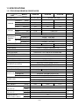
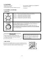
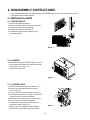
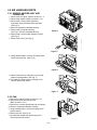
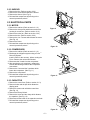
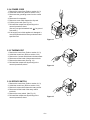
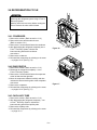
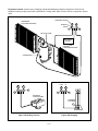
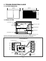
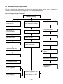
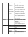
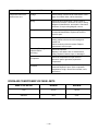
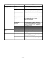
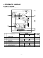
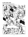
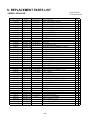
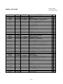
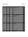
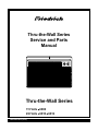
Thru-the-Wall Series
Service and Parts
Manual
Thru-the-Wall Series
115 Volts UE08
230 Volts UE10 UE12
UE08/UE10/UE12 (05/05)
CONTENTS
2.4 REFRIGERATION CYCLE..............................9
2.4.1 CONDENSER ........................................9
2.4.2 EVAPORATOR ......................................9
2.4.3 CAPILLARY TUBE.................................9
1. PREFACE
1.1 SAFETY PRECAUTIONS ...............................2
1.2 INSULATION RESISTANCE TEST.................2
1.3 SPECIFICATIONS ..........................................3
1.4 FEATURES .....................................................4
1.5 CONTROL LOCATIONS .................................4
3. TROUBLESHOOTING GUIDE
3.1 OUTSIDE DIMENSIONS...............................12
3.2 PIPING SYSTEM ..........................................12
3.3 TROUBLESHOOTING GUIDE......................13
2. DISASSEMBLY INSTRUCTIONS
2.1 MECHANICAL PARTS....................................5
2.1.1 FRONT GRILLE .....................................5
2.1.2 CABINET................................................5
2.1.3 CONTROL BOX .....................................5
2.2 AIR HANDLING PARTS..................................6
2.2.1 ORIFICE, HEATER ASSY AND TURBO FAN .........6
4. SCHEMATIC DIAGRAM
4.1 CIRCUIT DIAGRAM ......................................18
5. EXPLODED VIEW ..................................19
6. REPLACEMENT PARTS LIST .......20
2.2.2 FAN ........................................................6
2.2.3 SHROUD................................................7
2.3 ELECTRICAL PARTS .....................................7
2.3.1 MOTOR..................................................7
2.3.2 COMPRESSOR .....................................7
2.3.3 CAPACITOR ..........................................7
2.3.4 POWER CORD ......................................8
2.3.5 THERMOSTAT ......................................8
2.3.6 ROTARY SWITCH .................................8
1. PREFACE
This SERVICE MANUAL provides various service information, including the mechanical and electrical
parts etc. This room air conditioner was manufactured and assembled under a strict quality control system.
The refrigerant is charged at the factory. Be sure to read the safety precautions prior to servicing the unit.
1.1 SAFETY PRECAUTIONS
1.2 INSULATION RESISTANCE TEST
1. When servicing the unit, set the ROTARY SWITCH
or POWER SWITCH to OFF(O) and unplug the
power cord.
2. Observe the original lead dress.
If a short circuit is found, replace all parts which
have been overheated or damaged by the short
circuit.
3. After servicing the unit, make an insulation
resistance test to protect the customer from being
exposed to shock hazards.
1. Unplug the power cord and connect a jumper
between 2 pins (black and white).
2. The grounding conductor (green or green & yellow)
is to be open.
3. Measure the resistance value with an ohm meter
between the jumpered lead and each exposed
metallic part on the equipment at all the positions
(except OFF or O) of the ROTARY SWITCH or
POWER SWITCH.
4. The value should be over 1MΩ.
—2—
1.3 SPECIFICATIONS
1.3.1 FOR UE08A13B/UE10A33B/UE12A33B
MODELS
ITEMS
UE12A33B
9,800/10,000
11,400/11,700
(W)
830
1,040/1,060
1,210/1,250
RUNNING CURRENT (A)
7.5
5.2/4.7
6.2/5.8
E.E.R.
10.0
9.4
9.4
(Btu/h)
INPUT
(Btu/W.h)
(Btu/h)
3,850
9,200/11,200
(W)
1,230
2,900/3,500
RUNNING CURRENT (A)
10.7
14.0/15.3
CAPACITY
INPUT
INDOOR (°C)
OPERATING COOLING
OUTDOOR (°C)
TEMPERAINDOOR (°C)
TURE
HEATING
OUTDOOR (°C)
REFRIGERANT (R-22) CHARGE(g)
380(13.2 OZ)
26.7 (DB)
19.4 (WB)
35 (DB)
23.9 (WB)
21.1 (DB)
15.6 (WB)
8.3 (DB)
6.1 (WB)
440(15.5 OZ)
470(16.6 OZ)
2 ROW 11 STACKS LOUVEREDFIN TYPE
2 ROW 17 STACKS, L-BENDED TYPE
2 ROW 12 STACKS
EVAPORATOR
CONDENSER
TURBO FAN
FAN, INDOOR
PROPELLER TYPE FAN WITH SLINGER-RING
FAN, OUTDOOR
1/ 2/ 2
FAN SPEEDS (FAN/COOLING/HEATING)
6 POLES
FAN MOTOR
OPERATION CONTROL
ROTARY SWITCH
ROOM TEMP. CONTROL
THERMOSTAT
VERTICAL LOUVER (RIGHT & LEFT)
AIR DIRECTION CONTROL
HORIZONTAL LOUVER (UP & DOWN)
TOP-DOWN
CONSTRUCTION
1.2KW, 115V
ELECTRIC HEATER
COMPRESSOR
PROTECTOR
REMARK
1Ø, 208/ 230V, 60Hz
8,000
CAPACITY
HEATING
UE10A33B
1Ø, 115V, 60Hz
POWER SUPPLY
COOLING
UE08A13B
3.5KW, 208/230V
EXTERNAL OVERLOAD PROTECTOR
INTERNAL THERMAL PROTECTOR
FAN MOTOR
ELECTRIC HEATER
FUSE LINK, BIMETAL THERMOSTAT
1.6m (3 WIRE WITH GROUDING)
POWER CORD
ATTACHMENT PLUG (CORD-CONNECTED TYPE)
SPLASHED BY FAN SLINGER
DRAIN SYSTEM
73/33
80/36
NET WEIGHT
(lbs/kg)
DIMENSION
(inch)
2421/32 x 1413/32 x 1921/32
(W x H x D)
(mm)
626 x 366 x 499
SLEEVE DIMESION
(inch)
257/8 x 1517/32 x 1623/32
(W x H x D)
(mm)
656 x 394 x 425
SLEEVE DEPTH
(inch)
20
WITH FRONT GRILLE
(mm)
510
—3—
81/37
OPTIONAL
PART
1.4 FEATURES
• Designed for cooling only.
• Built in adjustable THERMISTOR and THERMOSTAT.
• Powerful and quiet cooling.
• Top-down chassis for the simple installation and service.
• Washable one-touch filter.
• Compact size.
1.5 CONTROL LOCATIONS
• OPERATION
Off
Fan Only
Low Cool
High Cool
Low Heat
High Heat
- Turns the air conditioner off.
- The low fan speed operation without cooling (heating).
- Cooling with the low speed fan operation.
- Cooling with the high speed fan operation.
- Heating with the low speed fan operation.
- Heating with the high speed fan operation.
Turn the Temperature Knob to the desired setting. The central position is a normal
setting for average conditions. You can change this setting, if necessary, in
accordance with your temperature preference.
The thermostat automatically controls cooling or heating, but the fan runs
continuously whenever the air conditioner is in operation. If the room is too warm,
turn the thermostat control clockwise. If the room is too cool, turn the thermostat
control counterclockwise.
CAUTION
A slight burning odor may come from the unit
when first switching to HEAT after the cooling
season is over. This odor, caused by fine dust
particles on the heater, will disappear quickly.
This is normal operation.
When the air conditioner has been operating in the
cooling or heating mode and is turned off or set to the fan
only position, wait at least 3 minutes before resetting to
the cooling operation again.
• VENTILATION
Push the lever to the "CLOSE" position to cool, heat or recirculate room air only.
Pull the lever to the "OPEN" position to exhaust smoke or stale air from the room.
This feature is best used in conjunction with the FAN ONLY position.
PULL OPEN / PUSH CLOSE
—4—
2. DISASSEMBLY INSTRUCTIONS
— Prior to disassembling the unit, make sure that the POWER switch is set to OFF and the power cord is
unplugged from the wall receptacle.
2.1 MECHANICAL PARTS
2.1.1 FRONT GRILLE
1. Open the inlet grille downward.
2. Remove the screw which fastens the front grille.
3. Pull the front grille from the right side.
4. Remove the front grille. (See Fig. 1)
5. Re-install the component by referring to the
removal procedure.
Figure 1
2.1.2 CABINET
1. After disassembling the FRONT GRILLE, remove
the 9 screws which fasten the cabinet at the both
sides and the top. (See Fig. 2)
Keep these for later use.
Figure 2
2.1.3 CONTROL BOX
1. Remove the front grille. (Refer to section 2.1.1)
2. Remove the screw which fasten the control
box. (See Fig. 3)
3. Pull the control box from the barrier.(See Fig.3)
4. Discharge the capacitor by placing a 20,000 ohm
resistor across the capacitor terminals.
5. Disconnect two wire housings in the control box.
6. Pull the control box forward completely.
7. Re-install the components by referring to the
removal procedure. (See Fig. 3)
(Refer to the circuit diagram found on pages
29~30 in this manual and on the control box.)
Figure 3
—5—
2.2 AIR HANDLING PARTS
2.2.1 ORIFICE, HEATER ASSY AND
TURBO FAN
1. Remove the front grille. (Refer to section 2.1.1)
2. Remove the cabinet. (Refer to section 2.1.2)
3. Remove the 2 screws which fasten the
evaporator at the left side and the right side.
(See Fig. 4)
4. Move the evaporator sideward carefully.
5. Remove the 2 terminals carefully
(See Fig. 5, Electric Heater Model only)
6. Remove the 4 screws which fasten the orifice.
(See Fig. 5)
7. Remove the orifice. (See Fig. 5)
Figure 4
Figure 5
8. Using handheld pliers, remove the clamp which
secures the turbo fan. (See Fig. 6)
Figure 6
9. Remove the turbo fan with pliers or your hand,
without touching blades. (See Fig. 7)
10. Re-install the components by referring to the
removal procedures, above.
Figure 7
2.2.2 FAN
1. Remove the cabinet. (Refer to section 2.1.2)
2. Remove the brace and shroud cover.
(Refer to section 2.2.1)
3. Remove the 6 screws which fasten the condenser.
4. Move the condenser sideways carefully.
5. Using handheld pliers, remove the clamp which
secures the fan.
6. Remove the fan. (See Fig. 8)
7. Re-install the components by referring to the
removal procedures, above.
Figure 8
—6—
2.2.3 SHROUD
1. Remove the fan. (Refer to section 2.2.2)
2. Remove the screw which fastens the shroud.
3. Remove the shroud. (See Fig. 9)
4. Re-install the components by referring to the
removal procedures, above.
2.3 ELECTRICAL PARTS
2.3.1 MOTOR
1. Remove the cabinet. (Refer to section 2.1.2)
2. Remove the clamp cord and disconnect the wire
housing in control box. (Refer to section 2.1.3)
3. Remove the turbo fan. (Refer to section 2.2.2)
4. Remove the fan. (Refer to section 2.2.2)
5. Remove the 4 or 2 screws which fasten the motor.
(See Fig. 10)
6. Remove the motor.
7. Re-install the components by referring to the
removal procedures, above.
Figure 9
Figure 10
2.3.2 COMPRESSOR
1. Remove the cabinet. (Refer to section 2.1.2)
2. Discharge the refrigerant system using a FreonTM
Recovery System.
Install a valve for the recovery, before venting the
Freon. Remove the valve when finished.
3. Disconnect the 3 leads from the compressor.
4. After purging the unit completely, unbraze the
suction and discharge tubes at the compressor
connections.
5. Remove the 3 nuts and the 3 washers which
fasten the compressor. (See Fig. 11)
6. Remove the compressor.
7. Re-install the components by referring to the
removal procedures, above.
Figure 11
2.3.3 CAPACITOR
1. Remove the control box. (Refer to section 2.1.3)
2. Remove knobs and the tips which fasten the
display panel.
3. Remove 2 screws and unfold the control box.
(See Fig. 12)
4. Remove the Rotary Switch.
5. Remove the screw and the clamp which fastens
the capacitor. (See Fig. 12)
6. Disconnect all the leads on the capacitor terminals.
7. Re-install the components by referring to the
removal procedures, above.
Figure 12
—7—
2.3.4 POWER CORD
1. Remove the control box. (Refer to section 2.1.3)
2. Unfold the control box. (Refer to section 2.3.3)
3. Disconnect the grounding screw from the control
box.
4. Disconnect 2 receptacles.
5. Remove a screw which fastens the clip cord.
6. Pull the power cord. (See Fig. 13)
7. Re-install the components by referring to the
removal procedure, above.
(Use only one ground-marked hole, , for ground
connection.)
8. If the supply cord of this appliance is damaged, it
must be replaced with the factory-authorized and
specified cord.
Figure 13
2.3.5 THERMOSTAT
1. Remove the control box. (Refer to section 2.1.3)
2. Unfold the control box. (Refer to section 2.3.3)
3. Remove the 2 screws which fasten the thermostat.
4. Disconnect all the leads of thermostat terminals.
5. Remove the thermostat. (See Fig. 14)
6. Re-install the components by referring to the
removal procedures, above.
Figure 14
2.3.6 ROTARY SWITCH
1. Remove the control box. (Refer to section 2.1.3)
2. Unfold the control box. (Refer to section 2.3.3)
3. Remove 2 screws which fasten the rotary switch.
4. Disconnect all the leads of the rotary switch
terminals.
5. Remove the rotary switch. (See Fig. 15)
6. Re-install the components by referring to the
removal procedure, above.
Figure 15
—8—
2.4 REFRIGERATION CYCLE
CAUTION
Discharge the refrigerant system using a FreonTM
Recovery System.
Install a valve for the recovery before venting the
Freon. Remove the valve when finished.
2.4.1 CONDENSER
1. Remove the cabinet. (Refer to section 2.1.2)
2. Remove the brace and the shroud cover.
(Refer to section 2.2.1)
3. Remove the 5 screws which fasten the condenser.
4. After discharging the refrigerant completely into a
FreonTM Recovery System, unbraze the
interconnecting tube at the condenser
connections.
5. Remove the condenser.
6. Re-install the components by referring to the notes
– on pages 13-14. (See Fig. 16)
Figure 16
2.4.2 EVAPORATOR
1. Remove the cabinet. (Refer to section 2.1.2)
2. Discharge the refrigerant completely – into a
FreonTM Recovery System.
3. Remove the 2 screws which fasten the evaporator
at the left side and the right side.
4. Move the evaporator sideward carefully and then
unbraze the interconnecting tube at the evaporator
connectors.
5. Remove the evaporator.
6. Re-install the components by referring to the notes
– on pages 13-14. (See Fig. 17)
Figure 17
2.4.3 CAPILLARY TUBE
1. Remove the cabinet. (Refer to section 2.1.2)
2. After discharging the refrigerant completely – into
a FreonTM Recovery System, unbraze the
interconnecting tube at the capillary tube.
3. Remove the capillary tube.
4. Re-install the components by referring to the notes
– on page 13-14.
—9—
NOTES
— Replacement of the refrigeration components
1. When replacing the refrigeration components, be
sure todischarge the refrigerant system using
a FreonTM recovery System.
Install a valve for the recovery before venting the
Freon. Remove the valve when finished.
2. After discharging the unit completely, remove the
desired component, and unbrace the pinch-off
tubes.
3. Solder service valves into the pinch-off tube ports,
leaving the valves open.
4. Solder the pinch-off tubes with Service valves.
5. Evacuate as follows.
1) Connect the vacuum pump, as illustrated Fig.
18A.
2) Start the vacuum pump, slowly open manifold
valves A and B with two full turns
counterclockwise and leave the valves closed.
The vacuum pump is now pulling through valves
A and B up to valve C by means of the manifold
and entire system.
CAUTION
If high vacuum equipment is used, just crack
valves A and B for a few minutes, then open
slowly with the two full turns counterclockwise.
This will keep oil from foaming and being
drawn into the vacuum pump.
3) Operate the vacuum pump for 20 to 30 minutes,
until 600 microns of vacuum is obtained. Close
valves A and B, and observe vacuum gauge for
a few minutes. A rise in pressure would
indicate a possible leak or moisture remaining in
the system. With valves A and B closed, stop
the vacuum pump.
4) Remove the hose from the vacuum pump and
place it on the charging cylinder. See Fig. 18B.
Open valve C.
Discharge the line at the manifold connection.
5) The system is now ready for final charging.
6. Recharge as follows :
1) Refrigeration cycle systems are charged from the
High-side. If the total charge cannot be put
in the High-side, the balance will be put in the
suction line through the access valve which you
installed as the system was opened.
2) Connect the charging cylinder as shown in Fig. 18B.
With valve C open, discharge the hose at the
manifold connection.
3) Open valve A and allow the proper charge to
enter the system. Valve B is still closed.
4) If more charge is required, the high-side will not
take it. Close valve A.
5) With the unit running, open valve B and add the
balance of the charge.
a. Do not add the liquid refrigerant to the Lowside.
b. Watch the Low-side gauge; allow pressure to
rise to 30 lbs.
c. Turn off valve B and allow pressure to drop.
d. Repeat steps B and C until the balance of the
charge is in the system.
6) When satisfied the unit is operating correctly,
use the pinch-off tool with the unit still running
and clamp on to the pinch-off tube. Using a tube
cutter, cut the pinch-off tube about 2 inches from
the pinch-off tool. Use sil-fos solder and solder
pinch-off tube closed. Turn off the unit, allow it to
set for a while, and then test the leakage of the
pinch-off connection.
—10—
Equipment needed: Vacuum pump, Charging cylinder, Manifold gauge, Brazing equipment. Pinch-off tool
capable of making a vapor-proof seal, Leak detector, Tubing cutter, Hand Tools to remove components, Service
valve.
COMPOUND GAUGE
CONDENSER
(HIGH PRESSURE SIDE)
MANIFOLD
GAUGE
A
B
CAPILLARY TUBE
SEE INSETS
BELOW
EVAPORATOR
(LOW PRESSURE SIDE)
COMPRESSOR
LOW
HI
A
B
B
A
EXTERNAL
VACUUM PUMP
CHARGING
CYLINDER
C
Figure 18A-Pulling Vacuum
Figure 18B-Charging
—11—
3. TROUBLESHOOTING GUIDE
3.1 OUTSIDE DIMENSIONS
24-21/32"
(626mm)
14-13/32"
(366mm)
19-21/32"
(499mm)
3.2 PIPING SYSTEM
CONDENSER COILS
FAN
CAPILLARY TUBE
MOTOR
COMPRESSOR
TURBO FAN
EVAPORATOR COILS
: REFRIGERANT FLOW
Following is a brief description of the important components and their functions in the refrigeration system.
Refer to Fig.19 to follow the refrigeration cycle and the flow of the refrigerant in the cooling cycle.
ROOM AIR CONDITIONER
CYCLE OF REFRIGERATION
EVAPORATOR COILS
CONDENSER COILS
COMPLETE LIQUID
BOIL OFF POINT
COOLED
AIR
SUCTION LIME
COOL LOW PRESSURE VAPOR
VAPOR INLET
HOT
DISCHARGED
AIR
ROOM AIR HEAT LOAD
MOTOR
OUTSIDE COOLING
AIR FOR REFRIGERANT
PASS THROUGH
COMPRESSOR
OIL
LIQUID
PRESSURE
DROP
LIQUID OUTLET
(LIQUID REFRIGERANT)
HIGH PRESSURE VAPOR
LIQUID PEFRIGERANT
CAPILLARY TUBE
Figure 19
—12—
LOW PRESSURE VAPOR
3.3 TROUBLESHOOTING GUIDE
In general, possible trouble is classified in two causes.
The one is called Starting Failure which is caused from an electrical defect, and the other is Ineffective Air
Conditioning caused by a defect in the refrigeration circuit and improper application.
Unit is running but cooling is ineffective
Ineffective Cooling
Check cold air circulation
for smooth flow.
Check outdoor coil
(heat exchanger) & the fan
operation.
Dirty indoor coil
(Heat exchanger)
Check gas leakage.
Malfunction of fan
Repair gas leak.
Clogged air filter
Replacement of unit if the
unit is beyond repair.
Check heat load increase.
Unexpected residue
Overloaded Circuit
Check inside gas pressure.
Obstruction at air outlet
Adjusting of refrigerant
charge
Stop auto air-swing
Malfunction of compressor
Correct above troubles
Replacement of
compressor
Check clogging in
refrigeration circuit.
Repair clogging in
refrigeration circuit.
Satisfactory operation with
temperature difference of
inlet & outlet air ; 18-26°F
—13—
Fails to Start
Check power source.
Check circuit breaker
and fuse.
Check control switch
setting.
Gas leakage at feeler bulb
of thermostat
Check control switch.
Only compressor fails to
start.
Only fan fails to start.
Improper wiring.
Drop in power voltage.
Improper thermostat setting
Defect of fan motor
capacitor.
Defective compressor
capacitor.
Loose terminal connection.
Check capacitor.
Irregular motor resistance
( ).
Irregular motor insulation
( ).
Improper wiring
Replacement.
Replacement of fan motor
Irregular motor resistance ( )
Regular but fails to start
Irregular motor insulation ( )
Replacement of compressor
(locking of rotor, metal)
Replacement of compressor
(Motor damaged)
—14—
COMPLAINT
Fan motor will not run.
CAUSE
REMEDY
No power
Check voltage at outlet. Correct if none.
Power supply cord
Check voltage to rotary switch. If none, check
power supply cord. Replace cord if circuit is open.
Rotary switch
Check switch continuity. Refer to wiring diagram
for terminal identification. Replace switch if
defective.
Wire disconnected or
connection loose
Connect wire. Refer to wiring diagram for terminal
identification. Repair or replace loose terminal.
Capacitor (Discharge
capacitor before testing.)
Test capacitor.
Replace if not within ±10% of manufacturer's
rating. Replace if shorted, open, or damaged.
Will not rotate
Fan blade hitting shroud or blower wheel hitting
scroll. Realign assembly.
Units using slinger ring condenser fans must
have 1/4 to 5/16 inch clearance to the base. If it is
hitting the base, shim up the bottom of the fan
motor with mounting screw(s).
Check fan motor bearings; if motor shaft will not
rotate, replace the motor.
Fan motor runs
intermittently
Revolves on overload.
Check voltage. See limits on page 18. If not within
limits, call an electrician.
Test capacitor.
Check bearings. Does the fan blade rotate freely?
If not, replace fan motor.
Pay attention to any change from high speed to
low speed. If the speed does not change, replace
the motor.
Fan motor noise.
Grommets
Check grommets; if worn or missing, replace them.
Fan
If cracked, out of balance, or partially missing,
replace it.
Turbo fan
If cracked, out of balance, or partially missing,
replace it.
Loose set screw
Tighten it.
Worn bearings
If knocking sounds continue when running or
loose, replace the motor. If the motor hums or
noise appears to be internal while running,
replace motor.
—15—
COMPLAINT
Compressor will not run,
but fan motor runs.
CAUSE
REMEDY
Voltage
Check voltage. See the limits at the bottom of this
page. If not within limits, call an electrician.
Wiring
Check the wire connections, if loose, repair or
replace the terminal. If wires are off, refer to wiring
diagram for identification, and replace. Check wire
locations. If not per wiring diagram, correct.
Rotary
Check for continuity, refer to the wiring diagram
for terminal identification. Replace the switch if
circuit is open.
Thermostat
Check the position of knob If not at the coldest
setting, advance the knob to this setting and
restart unit.
Check continuity of the thermostat. Replace
thermostat if circuit is open.
Capacitor (Discharge
capacitor before
servicing.)
Check the capacitor.
Replace if not within ±10% of manufacturers
rating. Replace if shorted, open, or damaged.
Compressor
Check the compressor for open circuit or
ground. If open or grounded, replace the
compressor.
Check the compressor overload, if externally
mounted. Replace if open. (If the compressor
temperature is high, remove the overload, cool it,
and retest.)
Overload
ROOM AIR CONDITIONER VOLTAGE LIMITS
NAME PLATE RATING
MINIMUM
MAXIMUM
115V
103.5V
126.5V
208/230V
187V
253V
—16—
COMPLAINT
Compressor cycles
on overload.
Insufficient cooling or
heating
Excessive noise.
REMEDY
CAUSE
Voltage
Check the voltage. See the limits on the preceding page. If not within limits, call an electrician.
Overload
Check overload, if externally mounted.
Replace if open. (If the compressor temperature
is high, remove the overload, cool, and retest.)
Fan motor
If not running, determine the cause. Replace if
required.
Condenser air flow
restriction
Remove the cabinet. Inspect the interior surface
of the condenser; if restricted, clean carefully
do not damage fins
s. Clean the interior
base before reassembling.
Condenser fins
(damaged)
If condenser fins are closed over a large area
on the coil surface, head pressures will increase,
causing the compressor to cycle. Straighten the
fins or replace the coil.
Test capacitor.
Check the terminals. If loose, repair or replace.
Check the system for a restriction.
If restricted, clean or replace.
Close if open.
Determine if the unit is properly sized for the area to
be cooled.
Check the set screw or clamp. If loose or missing,
correct. If the blower or fan is hitting air guide,
rearrange the air handling parts.
Remove the cabinet and carefully rearrange tubing
not to contact cabinet, compressor, shroud, and
barrier.
Capacitor
Wiring
Refrigerating system
Air filter
Exhaust damper door
Unit undersized
Blower or fan
Copper tubing
—17—
4. SCHEMATIC DIAGRAM
4.1 CIRCUIT DIAGRAM
• MODEL : UE08A13B/UE10A33B/UE12A33B
POWER INPUT
BK(BR)
(Plain)
ROTARY SWITCH
GN/YL
RD
8
7
2
1
WH(BL)
(Ribbed)
6
L
BL
4
H
BK
BL
BK
MOTOR
3
OR(BR)
2
1
CAPACITOR
YL
BL
YL
OR(BR)
F
THERMOSTAT
H
C
WH
4
C
5
BK
RD
RD
L
R
7
COMP
S
C
BR(YL)
BK
BK
C
RD
RD
H
BL
BL
O.L.P
RD
RD
FUSE LINK
WIRING DIAGRAM
NO.
DESCRIPTION
6
HEATER
BI-METAL
THERMOSTAT
8
3854AR3563D
PART NO.
UE08A13B
6411A20048F
UE10A33B
UE12A33B
6411A20048L
Q'TY
REPER SET MARKS
1
1
POWER CORD
2
ROTARY SWITCH
3
FAN MOTOR
67303019
4
CAPACITOR
67300714
5
THERMOSTAT
6
COMPRESSOR
67301625
67301623
2525UKHK2AA
1
7
OVERLOAD PROTECTOR
67301411
67301413
6750U-L039A
1
8
ELECTRIC HEATER
67301411
67300502
67303010
1
4681A20041M
67300711
1
1
67300404
—18—
1
67310100
1
5. EXPLODED VIEW
• MODEL: UE08A13B/UE10A33B/UE12A33B
E
G
130900
749180
147582-1
147582-2
147581
Co
ol
Ene
Savrgy
er
Fan
F1
F2 LOW
F3 MED
HIGH
MO
Tim
er
TIM
152302
'F
TE
DE
MP
ER
FA
SP N
EE
D
PO
WE
435301
R
135312
352390
135313
D
559010
349001
349480
148000
753010
F
W48602
753011
149980
354210
346811
554031
130410
349600
359012
249950
W48602
A
269310
266003
C
35211A
352113
B
567502
137215
554160
264110
352115
W0CZZ
149410
552111
—19—
550140
6. REPLACEMENT PARTS LIST
R: Service Parts
N: Non Service parts
• MODEL: UE08A13B
LOCATION NO.
130410
130900
135312
135313
137215
147581
147582-1
147582-2
147900
148000
149410
149980
152302
249950
264110
266003
269310
330720
346811
349480
349600
352113
35211A
352380
352390
354210
359012
435301
435301
550140
552111
554031
554160
559010
567502
749180
749740
753010
753011
W0CZZ
W38581
W48602
W54101
W5410C
MODEL
FRIEDRICH #
UE08A13B
67302917
UE08A13B
67303705
UE08A13B
67306006
UE08A13B
67306104
UE08A13B
67305504
UE08A13B
67306203
UE08A13B
67306252
UE08A13B
67306253
UE08A13B
UE08A13B
67303903
UE08A13B
67304102
UE08A13B
67303111
UE08A13B
67304304
UE08A13B
UE08A13B
UE08A13B
67300502
UE08A13B
67300404
UE08A13B
UE08A13B
67303019
UE08A13B
67303406
UE08A13B
67303607
UE08A13B
67400175
UE08A13B
67400174
UE08A13B
UE08A13B
67302720
UE08A13B
67302416
UE08A13B
67302608
UE08A13B
67307203
UE08A13B
UE08A13B
67305001
UE08A13B
67302217
UE08A13B
67303317
UE08A13B
67301625
UE08A13B
67303202
UE08A13B
67301411
UE08A13B
67303504
UE08A13B
UE08A13B
UE08A13B
67310101
UE08A13B
67300714
UE08A13B
UE08A13B
67302500
UE08A13B
UE08A13B
DESCRIPTION
BASE ASSEMBLY,SINGLE
CABINET
GRILLE ASSEMBLY,FRONT(SINGLE)
GRILLE,INLET
PANEL ASSEMBLY,CONTROL
LOUVER,HORIZONTAL
LOUVER,VERTICAL
LOUVER,VERTICAL
BARRIER,SINGLE
BRACE
KNOB ASSEMBLY
SHROUD
FILTER(MECH),A/C
CONTROL BOX ASSEMBLY,SINGLE
POWER CORD ASSEMBLY
SWITCH,ROTARY
THERMOSTAT ASSEMBLY
SCROLL
MOTOR ASSEMBLY,SINGLE
ORIFICE
MOUNT,MOTOR
TUBE ASSEMBLY,DISCHARGE SINGLE
TUBE ASSEMBLY,SUCTION SINGLE
AIR GUIDE
AIR GUIDE ASSEMBLY
EVAPORATOR ASSEMBLY,FIRST
FAN,TURBO
GRILLE,REAR
GRILLE,REAR
ISOLATOR,COMP
TUBE ASSEMBLY,CAPILLARY
CONDENSER ASSEMBLY,BENT
COMPRESSOR
FAN ASSEMBLY,AXIAL
O.L.P
FRAME
GUIDE
HEATER ASSEMBLY,ELECTRIC
HEATER,ELECTRIC
CAPACITOR,DRAWING
SHEET (MECH),VINYL
CLAMP,SPRING
INSULATION,ARTIRON
INSULATION,PE
—20—
QTY
1 R
1 R
1 R
1 R
1 R
1 R
1 R
1 R
1 R
1 R
1 R
1 R
1 R
1 R
1 R
1 R
1 R
1 R
1 R
1 R
1 R
1 R
1 R
1 R
1 R
1 R
1 R
1 R
1 R
1 R
1 R
1 R
1 R
1 R
1 R
1 R
1 R
1 R
1 R
1 R
1 R
1 R
1 R
1 R
R: Service Parts
N: Non Service parts
• MODEL: UE10A33B
LOCATION NO.
130410
130900
135312
135313
137215
147581
147582-1
147582-2
147900
148000
149410
149980
152302
249950
264110
266003
269310
330720
346811
349600
352113
352115
35211A
352380
352390
354210
359012
435301
435301
550140
552111
554031
554160
559010
567502
749180
749740
W0CZZ
W38581
W48602
W54101
W5410C
MODEL
FRIEDRICH #
UE10A33B
UE10A33B
67303705
UE10A33B
67306005
UE10A33B
67306104
UE10A33B
67305504
UE10A33B
67306203
UE10A33B
67306252
UE10A33B
67306253
UE10A33B
UE10A33B
67303903
UE10A33B
67304102
UE10A33B
67303111
UE10A33B
67304304
UE10A33B
UE10A33B
UE10A33B
67300502
UE10A33B
67300404
UE10A33B
UE10A33B
67303010
UE10A33B
67303607
UE10A33B
67400181
UE10A33B
67302010
UE10A33B
67400180
UE10A33B
UE10A33B
67302720
UE10A33B
67302416
UE10A33B
67302608
UE10A33B
67307201
UE10A33B
UE10A33B
67305001
UE10A33B
67302214
UE10A33B
67303316
UE10A33B
67301623
UE10A33B
67303202
UE10A33B
67301413
UE10A33B
67303504
UE10A33B
UE10A33B
67300711
UE10A33B
UE10A33B
67302500
UE10A33B
UE10A33B
DESCRIPTION
BASE ASSEMBLY,SINGLE
CABINET
GRILLE ASSEMBLY,FRONT(SINGLE)
GRILLE,INLET
PANEL ASSEMBLY,CONTROL
LOUVER,HORIZONTAL
LOUVER,VERTICAL
LOUVER,VERTICAL
BARRIER,SINGLE
BRACE
KNOB ASSEMBLY
SHROUD
FILTER(MECH),A/C
CONTROL BOX ASSEMBLY,SINGLE
POWER CORD ASSEMBLY
SWITCH,ROTARY
THERMOSTAT ASSEMBLY
SCROLL
MOTOR ASSEMBLY,SINGLE
MOUNT,MOTOR
TUBE ASSEMBLY,DISCHARGE SINGLE
TUBE ASSEMBLY,EVAPORATOR IN
TUBE ASSEMBLY,SUCTION SINGLE
AIR GUIDE
AIR GUIDE ASSEMBLY
EVAPORATOR ASSEMBLY,FIRST
FAN,TURBO
GRILLE,REAR
GRILLE,REAR
ISOLATOR,COMP
TUBE ASSEMBLY,CAPILLARY
CONDENSER ASSEMBLY,BENT
COMPRESSOR SET
FAN ASSEMBLY,AXIAL
O.L.P
FRAME
GUIDE
CAPACITOR,DRAWING
SHEET (MECH),VINYL
CLAMP,SPRING
INSULATION,ARTIRON
INSULATION,PE
—21—
QTY
1 R
1 R
1 R
1 R
1 R
1 R
1 R
1 R
1 R
1 R
1 R
1 R
1 R
1 R
1 R
1 R
1 R
1 R
1 R
1 R
1 R
1 R
1 R
1 R
1 R
1 R
1 R
1 R
1 R
1 R
1 R
1 R
1 R
1 R
1 R
1 R
1 R
1 R
1 R
1 R
1 R
1 R
R: Service Parts
N: Non Service parts
• MODEL: UE12A33B
LOCATION NO.
130410
130900
135312
135313
137215
147581
147582-1
147582-2
147900
148000
149410
149980
152302
249950
264110
266003
269310
330720
346811
349600
352113
352115
35211A
352380
352390
354210
359012
435301
550140
554031
554160
559010
567502
749180
749740
753010
W0CZZ
W38581
W48602
W54101
W5410C
MODEL
FRIEDRICH #
UE12A33B
67302918
UE12A33B
67303705
UE12A33B
67306005
UE12A33B
67306104
UE12A33B
67305504
UE12A33B
67306203
UE12A33B
67306252
UE12A33B
67306253
UE12A33B
UE12A33B
67303903
UE12A33B
67304102
UE12A33B
67303111
UE12A33B
67304304
UE12A33B
UE12A33B
UE12A33B
67300502
UE12A33B
67300404
UE12A33B
UE12A33B
UE12A33B
67303606
UE12A33B
UE12A33B
UE12A33B
UE12A33B
UE12A33B
67302720
UE12A33B
UE12A33B
67302608
UE12A33B
UE12A33B
67305001
UE12A33B
67303318
UE12A33B
UE12A33B
67303202
UE12A33B
UE12A33B
67303504
UE12A33B
UE12A33B
UE12A33B
67300711
UE12A33B
UE12A33B
67302500
UE12A33B
UE12A33B
DESCRIPTION
BASE ASSEMBLY,SINGLE
CABINET
GRILLE ASSEMBLY,FRONT(SINGLE)
GRILLE,INLET
PANEL ASSEMBLY,CONTROL
LOUVER,HORIZONTAL
LOUVER,VERTICAL
LOUVER,VERTICAL
BARRIER,SINGLE
BRACE
KNOB ASSEMBLY
SHROUD
FILTER(MECH),A/C
CONTROL BOX ASSEMBLY,SINGLE
POWER CORD ASSEMBLY
SWITCH,ROTARY
THERMOSTAT ASSEMBLY
SCROLL
MOTOR ASSEMBLY,SINGLE
MOUNT,MOTOR
TUBE ASSEMBLY,DISCHARGE SINGLE
TUBE ASSEMBLY,EVAPORATOR IN
TUBE ASSEMBLY,SUCTION SINGLE
AIR GUIDE
AIR GUIDE ASSEMBLY
EVAPORATOR ASSEMBLY,FIRST
FAN,TURBO
GRILLE,REAR
ISOLATOR,COMP
CONDENSER ASSEMBLY,BENT
COMPRESSOR SET
FAN ASSEMBLY,AXIAL
O.L.P
FRAME
GUIDE
HEATER ASSEMBLY,ELECTRIC
CAPACITOR,DRAWING
SHEET (MECH),VINYL
CLAMP,SPRING
INSULATION,ARTIRON
INSULATION,PE
—22—
QTY
1 R
1 R
1 R
1 R
1 R
1 R
1 R
1 R
1 R
1 R
1 R
1 R
1 R
1 R
1 R
1 R
1 R
1 R
1 R
1 R
1 R
1 R
1 R
1 R
1 R
1 R
1 R
1 R
1 R
1 R
1 R
1 R
1 R
1 R
1 R
1 R
1 R
1 R
1 R
1 R
1 R
FRIEDRICH AIR CONDITIONING CO.
Visit our web site at www.friedrich.com
Post Office Box 1540 • 4200 N. Pan Am Expressway • San Antonio, Texas 78295-1540
• (210) 357-4400 • FAX (210) 357-4480
P/NO.:3828A20040G
Printed in the U.S.A
UE08/UE10/UE12 (05/05)