1
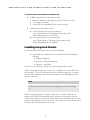
medTester 5000C Automated Biomedical Equipment Test System Field Upgrade Installation Instructions PN 2245628 April 2005 2005 Fluke Corporation, All rights reserved. Printed in USA All product names are trademarks of their respective companies M E D T E S T E R 5 0 0 0 C F I E L D U P G R A D E I N S T A L L A T I O N I N S T R U C T I O N S medTester 5000C Field Upgrade Installation Instructions These instructions tell you how to perform an instrument firmware upgrade to a medTester 5000C and how to install optional modules into a Fluke Biomedical medTester 5000C. Note If you ordered more than one module and/or upgrade, you have received more than one set of these instructions. But you can perform all installations at the same time with one set of instructions. Before You Begin In these instructions, upgrade means that you are bringing up to date the firmware in your medTester 5000. Upgrading involves replacing firmware integrated circuits (ICs). Enabling modules means that you are installing software from diskettes to your medTester in order to make medTester modules available for use. In some cases you need to install additional ICs that work with specific medTester 5000C modules. These are the modules for Expanded Memory, and medCheck. You have received all of the parts necessary to perform the installation yourself and to enable individual medTester 5000C modules. If you have already had Fluke Biomedical upgrade your medTester or install modules at the factory, you are receiving the module installation disks in the event that you need to reinstall the modules later. Please save these instructions with your installation disks. Your instrument is ready to use. 1 M E D T E S T E R 5 0 0 0 C F I E L D U P G R A D E I N S T A L L A T I O N I N S T R U C T I O N S NOTE: IMPORTANT When upgrading your 5000C firmware, all memory for test records and checklists will be erased. Process all current medTester test records first. For example, upload them to your compatible CMMS or print them. Note If you are installing a medTester 5000C firmware Upgrade; and Modules 4 or 7; install your ICs before enabling the module(s). Module Identification Modules are identified by number according to the following table: Module Number Module Name 2 RS-232/PRINTER 3 100 RECORDS 4 EXPANDED MEMORY 5 WAVES/EXTENDED TEST 6 DATA TRANSFER 7 MEDCHECK 8 DEFIBRILLATOR 9 IV PUMP 10 CMMS INTERFACE 11 ESU 12 SPO2 13 TRANSCUTANEOUS PACER 14 NIBP 2 M E D T E S T E R 5 0 0 0 C F I E L D U P G R A D E I N S T A L L A T I O N I N S T R U C T I O N S Module and Upgrade Parts Check that you have received the following parts with your module or upgrade: Firmware Upgrade • 2 IC RAM chips (40-pin devices, labeled U20 and U21) Modules 2, 3, 5, 6, 8, 9, 10, 11, 12, 13, and 14 • Installation disk, 1 for each module Module 4 Expanded Memory • Installation disk • IC RAM (32-pin device without label) Module 7 medCheck • Installation disk • 4 IC RAMs (32-pin device without label) Note If you are upgrading your medTester 5000C firmware, and your medTester currently includes medCheck, then your medCheck Module does not include the four (4) RAM ICs because they are already in your medTester. However, you may have received the installation disk in the event you need to reinstall it. Required Equipment for Upgrade/Modules To install a medTester 5000 firmware upgrade or to enable a medTester 5000C module, you need: For a -medTester 5000C Firmware Upgrade or to install modules that contain ICs (integrated circuits) • a knife (not needed if the quality sticker has previously been removed); • a Phillips screwdriver, #2-type; • an IC removal tool (not needed for instruments with lever handle IC sockets). 3 M E D T E S T E R 5 0 0 0 C F I E L D U P G R A D E I N S T A L L A T I O N I N S T R U C T I O N S To install modules that include an installation disk • an IBM-compatible personal computer with: 9 Microsoft Windows Operating Systems (95, 98, 2000, or XP); 9 a 3.5" floppy disk drive; 9 a serial port (or compatible USB to serial converter). • a medTester-to-PC interface cable: 1. If your computer has a 25-pin serial port: use a 25-pin female to 25-pin female null-modem cable (Fluke Biomedical part no. 2392186). 2. If your computer has a 9 pin serial port: use a 25-pin female to 9-pin female, null-modem cable (Fluke Biomedical part no. 2200102). Installing Integrated Circuits Use the procedures described in this section for installing: 1. Any modules that include ICs to be installed inside the instrument, including: • Firmware Upgrade • Module 4: Expanded Memory • Module 7: medCheck If you are not installing ICs, skip to the section Enabling Modules below. All ICs (integrated circuits) have a notch, dot, or dimple on one end. This is the end with pin 1. All the ICs referenced here are oriented so that pin 1 is towards the rear of the instrument. Note the notch marked on the PCB (printed circuit board) on that end. Note Always orient an IC correctly when installing it or you could damage it. All ICs are referenced by a U number (U20, U21, etc.). The U numbers are marked on the PCB. When installing an IC, make sure all the pins go into the socket holes and none are stuck out or bent under. If the instrument doesn't work correctly after installing an IC, check that it is the correct IC, that all the pins are in the holes, and that the orientation is correct. 4 M E D T E S T E R 5 0 0 0 C F I E L D U P G R A D E I N S T A L L A T I O N I N S T R U C T I O N S IC Removal and Installation Description There are two types of IC sockets which you may encounter—one that is plain, and one that has a lever handle. ICs are removed or installed as follows: Plain Socket IC Removal • Hook the IC removal tool under each end of the IC, and pull it out of the socket, OR • Insert a small flat-bladed screwdriver under alternate ends, and carefully pry them up until the IC comes out. Plain Socket IC Installation • Press the IC into the socket firmly. Lever Handle IC Socket Removal • Hold down the IC firmly with a finger, and • Pull the lever up. Remove the IC by hand. Lever Handle IC Socket Insertion • Make sure the lever is up. • Insert the IC by hand. • Push the lever to one side to lock in the IC. 5 M E D T E S T E R 5 0 0 0 C F I E L D U P G R A D E I N S T A L L A T I O N I N S T R U C T I O N S IC Installation Procedure This section describes the procedure you can use to install ICs. It includes instructions for the disassembly of the medTester 5000, replacement and installation of ICs, testing of your IC installation, and reassembly. Note This is your authorization to remove the Quality seal and to open the instrument case to install legitimately purchased upgrades and modules. DANGER—UNPLUG THE INSTRUMENT POWER CORD! Service should only be performed by qualified personnel. There are dangerous voltages present inside this instrument. Always unplug the power cord before opening the case. Never plug in the power cord while the case is open. Disassembly Disassembly involves opening the medTester case in order to access ICs. To disassemble: 1. Peel off the Quality seal sticker that seals the case halves together. Discard it. 2. Remove the nine (9) screws and lockwashers holding the top case to the bottom case. There are four (4) on top, two (2) in the front, and three (3) in the back. 3. Pull the case halves apart. Pull the top half forward while turning it upside down and lay it down. There are cables connecting the two halves together. Take notice of these—if they come apart, you will know how to put them back together. 4. Remove the six (6) screws holding the metal shield to the digital PCB (printed circuit board). 6 M E D T E S T E R 5 0 0 0 C F I E L D U P G R A D E I N S T A L L A T I O N I N S T R U C T I O N S Install Integrated Circuits 1. For a medTester 5000C Firmware Upgrade, remove IC U20 and U21 on the digital PCB, and install the new U20 and U21 (40-pin devices with labels). 2. For Modules 4 (Expanded Memory) and 7 (medCheck), install all the RAM ICs (32-pin devices without labels) that you have received in the next available positions—U23, U24, U25, U26, U27, in that order. Test the Installation 1. Fold the two case halves back together temporarily, closing the case. 2. Plug in the instrument, turn on the power: A. For a Firmware Upgrade an initialization will be performed automatically. B. Calibration is not affected by this initialization, so the instrument remains calibrated. C. The instrument should display a startup message, then display MAIN MENU 1. D. Test the RAMs: From MAIN MENU 1, press F5 UTIL, then RIGHT arrow, then F2 DIAG, then F4 MEMORY, then F2 RAM. The indicated RAM ICs should test GOOD: • All instruments: U22 • With Module 4 Expanded Memory: U23 • With Module 7 medCheck: U24, U25, U26, and U27 • Press Esc enough times to return to MAIN MENU 1. Reassembly Reassemble the instrument now. 1. You should have temporarily closed the case. With the unit unplugged, now open the case again by unfolding the top case and laying it down. 2. Attach the shield to the digital PCB with the six (6) screws. These are the steel screws without lockwashers. 3. Make sure all cables are still in place. If they have slipped off, reconnect them firmly. 7 M E D T E S T E R 5 0 0 0 C F I E L D U P G R A D E I N S T A L L A T I O N I N S T R U C T I O N S 4. Fold the case halves back together. Attach the top case to the bottom case with the nine (9) screws and lockwashers. These are the stainless steel screws. Enabling Modules Perform the steps described below for installing Modules 2 through 14. You need to install each module from its separate diskette. Installation requires running a program on an IBM-compatible personal computer. Note You MUST install the modules that you have received in numerical order, starting with Module 2, or the lowest numbered module you have. Installing modules in numerical order will lead to a successful installation. 1. Use the medTester 5000C COM1 port. 2. Decide on a computer COM port—(COM1 through COM4). 3. Decide on a baud rate—(300, 600, 1200, 2400, 4800, 9600, or 19200). 4. To change the medTester baud rate from MAIN MENU 1: A. Press F5 UTIL, then F1 BAUD; B. Select the COM1 port; C. Press F4 BAUD until the desired baud rate is displayed; D. Press F5 STORE; Press Esc twice to return to MAIN MENU 1. Note If Module 2 (RS-232/Printer) has not yet been installed, the medTester baud rate is not selectable and can not be adjusted. It is permanently set to 9600. After you install Module 2, you can change the baud rate. 5. Connect the computer COM port to the medTester COM1 port (medTester to PC null modem serial cable). 8 M E D T E S T E R 5 0 0 0 C F I E L D U P G R A D E I N S T A L L A T I O N I N S T R U C T I O N S 6. Run the computer in DOS mode (command prompt). Note If running Windows 95 or 98, with the mouse you can click and hold the Start button, then select Programs and MS-DOS Prompt. If running Windows 2000 or XP, with the mouse click the Start button, select Programs, Accessories, and Comnmand Prompt. 7. Insert the diskette into the computer's 3.5" floppy disk drive. 8. At the DOS prompt type this command: A:\INSTALL port baud <Enter> Where A is the floppy disk drive letter, A or B, and port is the computer COM port, 1 through 4, and baud is the selected baud rate: 300, 600, 1200, 2400, 4800, 9600, or 19200. Here’s an example of this command: A:\INSTALL 1 9600<Enter> 9. The program will install (enable) the module in the medTester. The computer should display MODULES SUCCESSFULLY LOADED. Note: If you have problems or get a different message, you can read the README file by typing A:README<Enter> for suggestions. Modules are customized for each instrument and can only be installed on the instrument with that specific serial number. Some modules need prerequisite modules to be installed first. Module 2 3 4 5 6 7 8 9 10 11 12 13 14 MODULE PREREQUISITE REQUIREMENTS Description Prerequisite RS232 / Printer None 100 Record Storage Module 2 Expanded Record Storage Modules 2 & 3 Waveforms / Extended Testing Modules 2 & 3 Data Transfer Modules 2 & 3 MedCheck Modules 2, 3, & 4 DEFIB Autosequences Modules 2,3, & 4 IVPUMP Autosequences Modules 2,3, & 4 Competitive CMMS Interface Modules 2,3,4,6 & 7 ESU Autosequences Modules 2,3, & 4 SPO2 Autosequences Modules 2,3, & 4 PACER Autosequences Modules 2,3, & 4 NIBP Autosequences Modules 2,3, & 4 9 M E D T E S T E R 5 0 0 0 C F I E L D U P G R A D E I N S T A L L A T I O N I N S T R U C T I O N S 7. To install more than one module, repeat steps seven (7) through nine (9) for each module which has an installation disk. Install them in numerical order. 8. If necessary, return to Windows from Command Prompt by typing: EXIT<Enter> at the DOS prompt. Confirming Module Installation 1. Turn the medTester 5000 power off to reset the microprocessor. 2. Turn the medTester 5000 power on. Check that the startup message shows the correct instrument serial number and the correct firmware version number. 3. Push F5 UTIL, then right arrow, then F3 MODULES. At this point, each press of F5 NEXT will sequentially scroll through each installed module allowing you to confirm the modules installed in the medTester 5000. 10