1
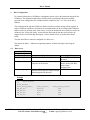
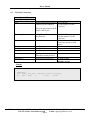
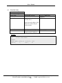
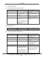
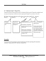
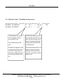
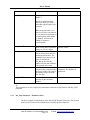
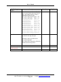
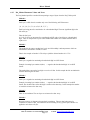
A Sierra Monitor Company
Driver Manual
(Supplement to the FieldServer Instruction Manual)
FS-8700-78 Dart
APPLICABILITY & EFFECTIVITY
Effective for all systems manufactured after January 18, 1999
Instruction Manual Part Number FS-8700-78
2/20/2003
Driver Manual
TABLE OF CONTENTS
1
2
3
4
5
6
7
Dart Driver Description ................................................................................................................1
1.1 Performance Issues................................................................................................................1
Driver Scope of Supply ................................................................................................................2
2.1 Supplied by Sierra Monitor for this driver ...............................................................................2
2.2 Provided by user....................................................................................................................2
Hardware Connections .................................................................................................................3
3.1 Hardware Configuration – Dart Present...................................................................................4
Basic Configuration .....................................................................................................................5
4.1 Data Arrays...........................................................................................................................5
4.2 Client Side Connections .........................................................................................................6
4.3 Client Side Nodes..................................................................................................................7
4.4 Client Side Map Descriptors ..................................................................................................8
4.4.1
FieldServer Specific Map Descriptor Parameters ..............................................................8
4.4.2
Timing Parameters..........................................................................................................8
4.4.3
Driver Specific Map Descriptor Parameters......................................................................8
4.4.4
Map Descriptor: Example 1 – Read all possible data .......................................................11
4.4.5
Map of How Data Aire Device Data is stored in a Data Array..........................................12
4.4.6
Unit Types ...................................................................................................................17
4.4.7
Map Descriptor: Example 2 – Writing a Set-Point ..........................................................19
4.4.8
Map Descriptor: Example 3 – Writing multiple points using one message. .......................20
Chapter 5...................................................................................................................................21
Advanced Topics .......................................................................................................................23
6.1 Additional Driver Specific Map Descriptor Parameters ..........................................................23
6.1.1
DA_Func Parameter - Permitted values..........................................................................24
6.1.2
DA_Field Parameter - Permitted values.........................................................................25
6.1.3
DA_Method Parameter Values and Notes.......................................................................27
6.1.4
Advanced Example 1 : ..................................................................................................28
6.1.5
Advanced Example 2....................................................................................................29
6.1.6
Advanced Map Descriptor: Example 3 - Using the 'special' parameter.............................30
6.1.7
Advanced Map Descriptor: Example 4 - Using the 'DA_Assoc' parameter. ......................31
6.1.8
Map Descriptor: Example 5 - Using a special / diagnostic command. ...............................32
6.2 Related Documents..............................................................................................................34
6.3 Troubleshooting Tips ...........................................................................................................34
6.3.1
Bad Values...................................................................................................................34
6.3.2
Dead Nodes..................................................................................................................34
6.3.3
Ignored Messages .........................................................................................................34
6.4 Writing data to Dap Devices ................................................................................................35
Revision Change Notices............................................................................................................36
7.1 Rev1.06a-Rev0 Changes from previous releases....................................................................36
FieldServer Technologies 1991 Tarob Court, Milpitas, California 95035 (408) 262-2299 fax: (408) 262-9042
Visit our website: www.fieldserver.com
E-mail: [email protected]
Page Index
Driver Manual
1
Dart Driver Description
The Dart Driver is designed for connection to a Data Air Coporation Dart Device.
The Dart device is a active element on a network of Data Air devices such as DAP panels. It
manages the devices and provides co-ordination and supervision. In performing these duties the
Dart device polls all the devices on the network for all the data. The Dart is capable of ‘echoing’
the responses from these devices on one of its RS232 ports. This driver is designed to listen
passively to these echoes and store device data. In addition the driver can send messages
(containing set point data, for example,) directly to individual devices on the network.
The FieldServer is connected to the RS232 serial port of the Dart. The Fieldserver can read and
write but active polling must be minimized as in reduces the amount of time that the DART
spends controlling the networked devices. The driver operates primarily as a passive client
listening to echoes of the data being polled by the DART. The DART must be set to ‘Echo’ mode
on the front panel of the Dart for the driver to operate correctly. There is no alternative to this
essential but manual setup-step.
The driver may be configured very simply (See example 1 in section 4 of the manual). In addition
a number of advanced configurations are possible. The manual is divided to separate the basic
and advanced topics.
The driver supports the common message formats for common Data Aire devices. A list of the
supported messages is provided in the manual. The driver cannot be used to configure or read the
status of a DART device itself.
The information that follows describes how to expand upon the factory defaults provided in the
configuration files included with the FieldServer.
1.1
Performance Issues
Several factors outside FieldServer’s control make for slow communications with Data Aire
devices. The Data Aire communications is based on a very low baud rate. In addition intermessage timing constraints and overhead requirements for active messages in a Dart
configuration add significant time to each transaction.
When a used with a DART device, writing to a set point (or other variable) may take up to 8
seconds to complete the transaction. The results of the write will not be seen until the DART has
timed-out back into control mode and echoes the new data to the Fieldserver. This could take
several minutes if there are many devices on the loop and will take at least 30 seconds.
When writing continuously, with DART configurations, the minimum time interval between
successive writes is 2 minutes and with non-DART configurations is 1.8 seconds.
FieldServer Technologies 1991 Tarob Court, Milpitas, California 95035 (408) 262-2299 fax: (408) 262-9042
Visit our website: www.fieldserver.com
E-mail: [email protected]
Page 1
Driver Manual
2
2.1
Driver Scope of Supply
Supplied by Sierra Monitor for this driver
RS485 connection adapter
Driver Manual.
2.2
Provided by user
Data Aire Dart and documentation
RS232 cable for the loop network
FieldServer Technologies 1991 Tarob Court, Milpitas, California 95035 (408) 262-2299 fax: (408) 262-9042
Visit our website: www.fieldserver.com
E-mail: [email protected]
Page 2
Driver Manual
3
Hardware Connections
Hardware
FieldServer Technologies 1991 Tarob Court, Milpitas, California 95035 (408) 262-2299 fax: (408) 262-9042
Visit our website: www.fieldserver.com
E-mail: [email protected]
Page 3
Driver Manual
3.1
Hardware Configuration – Dart Present
When a DART device is connected to the Data Aire field devices then the Fieldserver is connected to the
serial port of the DART. The DART must be set to ‘Echo’ mode. This is done on the front panel of the
DART.
FieldServer Technologies 1991 Tarob Court, Milpitas, California 95035 (408) 262-2299 fax: (408) 262-9042
Visit our website: www.fieldserver.com
E-mail: [email protected]
Page 4
Driver Manual
4
Basic Configuration
For a detailed discussion on FieldServer configuration, please refer to the instruction manual for the
FieldServer. The information that follows describes how to expand upon the factory defaults
provided in the configuration files included with the FieldServer (See “.csv” files on the driver
diskette).
The configuration file tells the FieldServer about its interfaces, and the routing of data required. In
order to enable the FieldServer for Dart Driver communications, the driver independent FieldServer
buffers need to be declared in the “Data Arrays” section, the destination device addresses need to be
declared in the “Client Side Nodes” section, and the data required from the servers needs to be
mapped in the “Client Side Map Descriptors” section. Details on how to do this can be found
below.
The Dart Serial Driver cannot be configured as a data server.
Note that in the tables, * indicates an optional parameter, with the bold legal value being the
default.
4.1
Data Arrays
Section Title
Data_Arrays
Column Title
Data_Array_Name
Function
Provide name for Data Array
Data_Format
Provide data format. Each data array can
only take on one format.
Data_Array_Length
Number of Data Objects. Must be larger
than the data storage area required for the
data being placed in this array.
Legal Values
Up to 15 alphanumeric
characters
FLOAT, BIT, UInt16,
SInt16, Packed_Bit, Byte,
Packed_Byte,
Swapped_Byte
1-10,000
Example
//
Data Arrays
//
Data_Arrays
Data_Array_Name,
DA_AI_01,
DA_AO_01,
DA_DI_01,
DA_DO_01,
Data_Format,
UInt16,
UInt16,
Bit,
Bit,
Data_Array_Length
200
200
200
200
FieldServer Technologies 1991 Tarob Court, Milpitas, California 95035 (408) 262-2299 fax: (408) 262-9042
Visit our website: www.fieldserver.com
E-mail: [email protected]
Page 5
Driver Manual
4.2
Client Side Connections
Section Title
Connections
Column Title
Port
Function
Specify which port the device is
connected to the FieldServer
Legal Values
P1-P8, R1-R2
(P1-P8) requires 232/485
converter.
This is the port connected to the
DART’s RS232 port.
Secondary_Port*
Using a Dart ? Do not specify
this parameter.
Baud*
Specify baud rate
Parity*
Data_Bits*
Stop_Bits*
Protocol
Specify parity
Specify data bits
Specify stop bits
Specify protocol used
Either keyword may be used.
Specify hardware handshaking
Time between internal polls
Handshaking*
Poll Delay*
P1-P8, R1-R2
(R1-R2) requires 232/485
converter.
2400 (Others available but
Daire only operates at 2400
baud.)
None
8
1
Dart
None
0-32000 seconds
default 1 second
Example
//
Client Side Connections
Connections
Port, Parity, Data_Bits, Stop_Bits, Protocol, Poll_Delay
P1,
2400 , None,
8,
1, Dart
, 0.100s
FieldServer Technologies 1991 Tarob Court, Milpitas, California 95035 (408) 262-2299 fax: (408) 262-9042
Visit our website: www.fieldserver.com
E-mail: [email protected]
Page 6
Driver Manual
4.3
Client Side Nodes
Section Title
Nodes
Column Title
Node_Name
Function
Provide name for node
Node_ID
This is not the node address of
the Dart device !
Legal Values
Up to 32 alphanumeric
characters
1-259
Specify the node address of the
DAP device whose data you
wish to monitor.
Protocol
Port
Specify protocol used
Specify which port the Dart is
connected to the FieldServer
Dart
P1-P8, R1-R2
Example
//
Client Side Nodes
Nodes
Node_Name, Node_ID, Protocol, Port
Unit1,
1,
Dart ,
P1
FieldServer Technologies 1991 Tarob Court, Milpitas, California 95035 (408) 262-2299 fax: (408) 262-9042
Visit our website: www.fieldserver.com
E-mail: [email protected]
Page 7
Driver Manual
4.4
4.4.1
Client Side Map Descriptors
FieldServer Specific Map Descriptor Parameters
Column Title
Map_Descriptor_Name
Function
Name of this Map Descriptor
Data_Array_Name
Name of Data Array where data
is to be stored in the
FieldServer
Starting location in Data Array
Data_Array_Location
Function
Function of Client Map
Descriptor
Legal Values
Up to 32 alphanumeric
characters
One of the Data Array names
from “Data Array” section
above
0 to maximum specified in
“Data Array” section above
RDBC, WRBC, WRBX,
Passive
The use of the WRBX keyword
is recommended for DART
configurations as
communications are minimized.
4.4.2
Timing Parameters
Column Title
Scan_Interval
4.4.3
Function
Rate at which data is polled
Legal Values
>0.1s
Driver Specific Map Descriptor Parameters
Column Title
Node_Name
Function
Name of Node to fetch data
from
Legal Values
One of the node names
specified in “Client Node
Descriptor” above
Length
Length of Map Descriptor
Address
Starting address of read block
1 The length must always be
set to one.
Not required for client
configuration. This parameters
is used in simulation
configuration only.
The following parameters apply only to the Dart Driver.
DA_Func*
Tell the driver to poll the device Everything
for all the data that is available.
The data is device specific.
See table 4.4.3.1 for a map of
how the data is stored in the
Other uses of this parameter are Fieldserver data arrays
permitted. These uses are
discussed in the Advanced
Topics section of this manual.
FieldServer Technologies 1991 Tarob Court, Milpitas, California 95035 (408) 262-2299 fax: (408) 262-9042
Visit our website: www.fieldserver.com
E-mail: [email protected]
Page 8
Driver Manual
DA_Field
Only required when the
function is a write (wrbc) or
when the map descriptor is
associated with a write by
means of the DA_Assoc
parameter value.
See Table 4.4.3.3 for a list of
permitted values.
This is the name of the data
field whose value you wish to
set in the device.
DA_Assoc
Other uses of this parameter are
permitted. These uses are
discussed in the Advanced
Topics section of this manual.
Use to associate passive map
descriptors with an active map
descriptor.
Any positive integer.
Using this parameter you
associate multiple fields with
one wrbc map descriptor, thus
reducing writing multiple
values to one device using just
one message.
FieldServer Technologies 1991 Tarob Court, Milpitas, California 95035 (408) 262-2299 fax: (408) 262-9042
Visit our website: www.fieldserver.com
E-mail: [email protected]
Page 9
Driver Manual
FieldServer Technologies 1991 Tarob Court, Milpitas, California 95035 (408) 262-2299 fax: (408) 262-9042
Visit our website: www.fieldserver.com
E-mail: [email protected]
Page 10
Driver Manual
4.4.4
Map Descriptor: Example 1 – Read all possible data
Map_Descriptor_Name, Data_Array_Name, Data_Array_Offset, Function, node_name, Address, Length, DA_Func
Read_Node_01,
DA_01
,0
, passive , Unit1
,0
, 1300 , Everything
The driver waits
passively for the
Dart to echo
data from the
devices.
No Scan Interval. The
driver will process data as
fast as the Dart can serve
it.
FieldServer Technologies 1991 Tarob Court, Milpitas, California 95035 (408) 262-2299 fax: (408) 262-9042
Visit our website: www.fieldserver.com
E-mail: [email protected]
Page 11
Driver Manual
4.4.5
Map of How Data Aire Device Data is stored in a Data Array
In the example of 4.4.1 the Fieldserver listens passively for all possible data from the device called ‘unit1’
and stores the data in an array called ‘DA_01’.
The data that is obtained from ‘unit1’ is dependent on the type of device. Irrespective of the device type
the arrangement of data, stored in DA_01, is fixed. If a data field cannot be obtained from ‘unit1’ then
the array is left with a zero value for that data field.
Table 4.4.5.1: Array Locations of ‘Everything’
In the following table the array location indicates the offset in the data array at which a data field can be
found. (This offset is relative to the offset specified in the map descriptor.) The columns headed 2,3 …
indicate the unit types for which the data fields are available. For example: The field ‘d_temp’ can be read
from unit types 2,5,6,7,9 but not from any of the other unit types. It is beyond the scope of this manual to
describe each field and to indicate valid ranges. Such information should be obtained from the Data Aire
Corporation.
‘x’ Indicates Read only
‘X’ Indicates a point that can be read & written.
‘w’ Indicates a write only point.
Array
Num
Location Method Elements
1
1
1
2
1
1
Data Field
Zone
Inhibit
2 3 4 5 6 7 8 9 14 15 Message Type
w w w w w w w w w Dap-Config
w w w w w w w w w Dap-Config
3
4
1
unitType
x x x x x x x x x x Dap-Unit
4
5
6
7
23
39
40
41
42
43
57
58
59
60
61
62
2
2
2
3
3
1
1
1
1
4
2
2
2
2
1
1
1
1
1
8
8
1
1
1
1
14
1
1
1
1
1
1
temp
hum
d_temp
mode
hold
cs_on
hs_on
valvePCT
hVlvPCT
errors
hiTemp
loTemp
hiHum
loHum
chilled_water
compressor_config
x
x
x
x
x
x
x
x
x
x
x
x
x
x
x
x
x
x
x
x
x
x
x
x
x
x
x
x
x
x
x
x
x
x
x
x
x
x
x
x
x
x
x
x
x
x
x
x
x
x
x
x
x
x
x
x
x
x
x
x
x
x
x
x
x
x
x
x
x
x
x
x
x
x
x
x
x
x
x
x
Dap-Stat
Dap-Stat
Dap-Stat
Dap-Stat
Dap-Stat
Dap-Stat
Dap-Stat
Dap-Stat
Dap-Stat
Dap-Stat
Dap-Stat
Dap-Stat
Dap-Stat
Dap-Stat
Dap-Stat
Dap-Stat
FieldServer Technologies 1991 Tarob Court, Milpitas, California 95035 (408) 262-2299 fax: (408) 262-9042
Visit our website: www.fieldserver.com
E-mail: [email protected]
Page 12
Driver Manual
63
64
65
66
67
68
69
70
71
72
1
1
1
1
1
1
1
1
1
1
1
1
1
1
1
1
1
1
1
1
heat_strip_config
hum_config
csUtilPct
hsUtilPct
valveUtilPct
humUtilPCT
alrm_select_1
alrm_select_2
alrm_select_3
alrm_select_4
x
x
x
x
x
x
x
x
x
x
x
x
x
x
x
x
x
x
x
x
x
x
x
x
x
x
x
x
x
x
x
x
x
x
x
x
x
x
x
x
x
x
x
x
x
x
x
x
x
x
Dap-Stat
Dap-Stat
Dap-Stat
Dap-Stat
Dap-Stat
Dap-Stat
Dap-Stat
Dap-Stat
Dap-Stat
Dap-Stat
73
3
56
bitErrors
x
x x x
x
Dap-Stat
185
186
187
188
189
190
191
192
193
194
195
196
197
198
218
258
259
260
261
1
1
1
1
1
1
1
1
1
1
1
1
1
4
6
1
2
2
1
1
1
1
1
1
1
1
1
1
1
1
1
1
20
10
1
1
1
1
runtime_c1
runtime_c2
runtime_c3
runtime_c4
runtime_ht1
runtime_ht2
runtime_ht3
runtime_hum
runtime_evap
runtime_cond
runtime_dehum
runtime_esc
runtime_cwc
errors
errage
version
tmbmair
tmbhum
tmbairdb
6
3
13
80
runtimes (as array)
bitErrors
x
x
x
x
x
x
x
x
x
x
x
x
x
x
x
x
x
x
x
x
x
x
x
x
x
x
x
x
x
x
x
x
x
x
x
x
x
x
x
x
x
x
x
x
x
x
x
x
x
x
x
x
x
x
x
x
x
x
x
x
x
x
x
x
x
x
Dap-Xtra
Dap-Xtra
Dap-Xtra
Dap-Xtra
Dap-Xtra
Dap-Xtra
Dap-Xtra
Dap-Xtra
Dap-Xtra
Dap-Xtra
Dap-Xtra
Dap-Xtra
Dap-Xtra
Dap-Xtra
Dap-Xtra
Dap-Xtra
Dap-Xtra
Dap-Xtra
Dap-Xtra
262
314
x
x
x
x
x
x
x
x
x
x
x
x
x
x
x
x
x
x
x
x
x
x
474
478
479
480
481
482
483
484
485
486
4
1
1
1
4
4
4
4
4
4
1
1
1
1
1
1
1
1
1
1
adj_rate
alrm_delay_1
alrm_delay_2
alrm_delay_3
alrm_enable_1
alrm_enable_2
alrm_enable_3
alrm_select_1
alrm_select_2
alrm_select_3
X
X
X
X
X
X
X
X
X
X
X
X
X
X
X
X
X
X
X
X
X
X
X
X
X
X
X
X
X
X
x
x
x
x
x
x
x
x
x
x
x
x
x
x
x
x
x
x
x
x
x
x
Dap-Xtra
Dap-Xtra
Dap-Menu
Dap-Menu
Dap-Menu
Dap-Menu
Dap-Menu
Dap-Menu
Dap-Menu
Dap-Menu
Dap-Menu
Dap-Menu
FieldServer Technologies 1991 Tarob Court, Milpitas, California 95035 (408) 262-2299 fax: (408) 262-9042
Visit our website: www.fieldserver.com
E-mail: [email protected]
Page 13
Driver Manual
487
488
489
490
491
492
493
494
495
496
497
498
499
500
501
502
503
504
505
506
507
508
509
510
511
512
513
514
515
516
517
518
1
1
1
2
1
1
1
2
1
1
1
1
1
2
2
1
1
2
1
1
1
1
1
2
1
1
1
1
1
2
2
1
1
1
1
1
1
1
1
1
1
1
1
1
1
1
1
1
1
1
1
1
1
1
1
1
1
1
1
1
1
1
1
1
chilled_water
compressor_config
c_mode
fire_lim
heat_strip_config
hi_cal
hi_h_cal
hi_t_lim
humid_config
h_calib
lead_lag
loc_h_deadband
loc_h_setpt
loc_t_dband
loc_t_setpt
lo_cal
lo_h_lim
lo_t_lim
main_int
passwd_a
passwd_b
rst_mode
s_delay
t_calib
voice
vvrg
cat1
cat2
cat3
d_calib
lo_d_lim
ptc
519
520
521
522
523
524
525
526
527
528
529
530
531
532
2
2
4
4
4
2
4
4
4
2
2
2
2
1
1
1
1
2
2
1
1
1
1
1
1
1
1
1
supplyT
returnT
coolOn1
coolOn2
coolOn3
valvePct
pumpsOn
condOn
modFail
hiSupT
loSupT
hiRetT
loRetT
csUtilPct1
X
X
X
X
X
X
X
X
X
X
X
X
X
X
X
X
X
X
X
X
X
X
X
X
X
X
X
X
X
X
X
X
X
X
X
X
X
X
X
X
X
X
X
X
X
X
X
X
X
X
X
X
X
X
X
X
X
X
X
X
X
X
X
X
x
x
x
x
x
x
x
x
x
x
x
x
x
x
x
x
x
x
x
x
x
x
x
x
x
x
x
x
X
X
X
X
X
X
X
X
X
X
X
X
X
X
X
X
X
X
X
X
X
X
X
X
X
X
X
X
X
X
X
X
Dap-Menu
Dap-Menu
Dap-Menu
Dap-Menu
Dap-Menu
Dap-Menu
Dap-Menu
Dap-Menu
Dap-Menu
Dap-Menu
Dap-Menu
Dap-Menu
Dap-Menu
Dap-Menu
Dap-Menu
Dap-Menu
Dap-Menu
Dap-Menu
Dap-Menu
Dap-Menu
Dap-Menu
Dap-Menu
Dap-Menu
Dap-Menu
Dap-Menu
Dap-Menu
Dap-Menu
Dap-Menu
Dap-Menu
Dap-Menu
Dap-Menu
Dap-Menu
x
x
x
x
x
x
x
x
x
x
x
x
x
x
Chiller-Stat
Chiller-Stat
Chiller-Stat
Chiller-Stat
Chiller-Stat
Chiller-Stat
Chiller-Stat
Chiller-Stat
Chiller-Stat
Chiller-Stat
Chiller-Stat
Chiller-Stat
Chiller-Stat
Chiller-Stat
FieldServer Technologies 1991 Tarob Court, Milpitas, California 95035 (408) 262-2299 fax: (408) 262-9042
Visit our website: www.fieldserver.com
E-mail: [email protected]
Page 14
Driver Manual
533
534
535
536
584
1
1
1
3
1
1
1
1
48
1
csUtilPct2
csUtilPct3
valveUtilPct
errors
mode
x
x
x
x
x
x
x
x
x
x
x
x
x
x
x
Chiller-Stat
Chiller-Stat
Chiller-Stat
Chiller-Stat
Chiller-Stat
585
596
676
6
3
6
11
80
10
runtimes
errold
errage
x x
x x
x x
x
x
x
Chiller-Xtra
Chiller-Xtra
Chiller-Xtra
854
855
856
857
858
859
860
861
862
863
864
865
866
867
868
869
870
871
872
873
874
875
879
883
887
888
889
890
891
892
893
894
895
896
897
898
4
4
2
4
2
4
4
4
2
2
4
2
2
1
4
1
1
1
4
4
1
4
4
4
4
4
4
1
1
2
4
4
4
4
1
1
1
1
1
1
1
1
1
1
1
1
1
1
1
1
1
1
1
1
1
1
1
4
4
4
1
1
1
1
1
1
1
1
1
1
1
1
adjust_rate
auto_ack
aux_setpt
backup_mods
backup_setpt
cmota
comp_type
ptc
hi_r_lim
hi_s_lim
LL_policy
lo_r_lim
lo_s_lim
main_int
mods_configd
network_ID
op_1_delay
op_2_delay
op_1_message
op_2_message
password
relay_mask_0
relay_mask_1
relay_mask_2
restart_mode
reverse_valve
sc_alarm_on
start_delay
supply_dband
supply_setpt
temp_scale
valve_voltage
voice
water_valve
return_cal
supply_cal
x
X
X
X
X
X
X
X
X
X
X
X
X
X
X
X
X
X
X
X
X
X
X
X
X
X
X
X
X
X
X
X
X
X
X
X
x
X
X
X
X
X
X
X
X
X
X
X
X
X
X
X
X
X
X
X
X
X
X
X
X
X
X
X
X
X
X
X
X
X
X
X
Chiller-Menu
Chiller-Menu
Chiller-Menu
Chiller-Menu
Chiller-Menu
Chiller-Menu
Chiller-Menu
Chiller-Menu
Chiller-Menu
Chiller-Menu
Chiller-Menu
Chiller-Menu
Chiller-Menu
Chiller-Menu
Chiller-Menu
Chiller-Menu
Chiller-Menu
Chiller-Menu
Chiller-Menu
Chiller-Menu
Chiller-Menu
Chiller-Menu
Chiller-Menu
Chiller-Menu
Chiller-Menu
Chiller-Menu
Chiller-Menu
Chiller-Menu
Chiller-Menu
Chiller-Menu
Chiller-Menu
Chiller-Menu
Chiller-Menu
Chiller-Menu
Chiller-Menu
Chiller-Menu
x
X
X
X
X
X
X
X
X
X
X
X
X
X
X
X
X
X
X
X
X
X
X
X
X
X
X
X
X
X
X
X
X
X
X
X
FieldServer Technologies 1991 Tarob Court, Milpitas, California 95035 (408) 262-2299 fax: (408) 262-9042
Visit our website: www.fieldserver.com
E-mail: [email protected]
Page 15
Driver Manual
899
900
901
902
903
904
905
906
907
908
909
910
911
912
913
914
915
916
917
918
919
920
921
922
923
924
925
926
927
928
929
930
931
932
933
934
950
966
982
998
1014
1030
1046
1062
1078
1079
1080
4
1
1
1
1
4
4
4
4
4
4
4
4
4
4
4
4
2
4
2
4
1
2
4
2
1
4
2
1
2
2
1
2
1
4
3
3
3
3
3
3
3
3
3
4
4
4
1
1
1
1
1
1
1
1
1
1
1
1
1
1
1
1
1
1
1
1
1
1
1
1
1
1
1
1
1
1
1
1
1
1
1
16
16
16
16
16
16
16
16
16
1
1
1
adj_rate
alrm_delay_1
alrm_delay_2
alrm_delay_3
alrm_delay_4
alrm_select_1
alrm_select_2
alrm_select_3
alrm_select_4
ant-enable
autoflush_time
auto_ack
comp_config
control_type
c_mode
da_volts
dehum_on
d_calib
esaver_supp_comp
fire_lim
heater_config
hi_h_lim
hi_t_lim
humid_config
h_calib
h_dband
lead_lag
lo_d_lim
lo_h_lim
lo_t_lim
main_int
network_id
nom_h_setpt
password
ptc
relay_1_mask_0
relay_1_mask_1
relay_1_mask_2
relay_2_mask_0
relay_2_mask_1
relay_2_mask_2
relay_3_mask_0
relay_3_mask_1
relay_3_mask_2
reverse_valve
rst_mode
sc_alarms
X
X
X
X
X
X
X
X
X
X
X
X
X
X
X
X
X
X
X
X
X
X
X
X
X
X
X
X
X
X
X
X
X
X
X
X
X
X
X
X
X
X
X
X
X
X
X
X
X
X
X
X
X
X
X
X
X
X
X
X
X
X
X
X
X
X
X
X
X
X
X
X
X
X
X
X
X
X
X
X
X
X
X
X
X
X
X
X
X
X
X
X
X
X
X
X
X
X
X
X
X
X
X
X
X
X
X
X
X
X
X
X
X
X
X
X
X
X
X
X
X
X
X
X
X
X
X
X
X
X
X
X
X
X
X
X
X
X
X
X
X
X
X
X
X
X
X
X
X
X
X
X
X
X
X
X
X
X
X
X
X
X
X
X
X
X
X
X
X
X
X
X
X
X
X
X
X
X
X
X
X
X
X
X
X
X
X
X
Dap80-Menu
Dap80-Menu
Dap80-Menu
Dap80-Menu
Dap80-Menu
Dap80-Menu
Dap80-Menu
Dap80-Menu
Dap80-Menu
Dap80-Menu
Dap80-Menu
Dap80-Menu
Dap80-Menu
Dap80-Menu
Dap80-Menu
Dap80-Menu
Dap80-Menu
Dap80-Menu
Dap80-Menu
Dap80-Menu
Dap80-Menu
Dap80-Menu
Dap80-Menu
Dap80-Menu
Dap80-Menu
Dap80-Menu
Dap80-Menu
Dap80-Menu
Dap80-Menu
Dap80-Menu
Dap80-Menu
Dap80-Menu
Dap80-Menu
Dap80-Menu
Dap80-Menu
Dap80-Menu
Dap80-Menu
Dap80-Menu
Dap80-Menu
Dap80-Menu
Dap80-Menu
Dap80-Menu
Dap80-Menu
Dap80-Menu
Dap80-Menu
Dap80-Menu
Dap80-Menu
FieldServer Technologies 1991 Tarob Court, Milpitas, California 95035 (408) 262-2299 fax: (408) 262-9042
Visit our website: www.fieldserver.com
E-mail: [email protected]
Page 16
Driver Manual
4.4.6
1081
1082
1083
1084
1085
1086
1
2
1
2
4
4
1
1
1
1
1
1
s_delay
t_calib
t_dband
t_setpt
valve_config
voice
1100
1101
1102
1103
1104
1105
1106
1107
1108
1109
1110
1111
1
1
1
1
1
1
1
1
1
1
1
1
1
1
1
1
1
1
1
1
1
1
1
1
1112
1113
1114
1
1
1
1
1
1
X
X
X
X
X
X
X
X
X
X
X
X
X
X
X
X
X
X
X
X
X
X
X
X
Dap80-Menu
Dap80-Menu
Dap80-Menu
Dap80-Menu
Dap80-Menu
Dap80-Menu
sensor_1_name
sensor_1_units
sensor_1_type
sensor_1_min_val
sensor_1_max_val
sensor_1_cal
sensor_2_name
sensor_2_units
sensor_2_type
sensor_2_min_val
sensor_2_max_val
sensor_2_cal
x
x
x
x
x
x
x
x
x
x
x
x
x
x
x
x
x
x
x
x
x
x
x
x
Dap80-Analog
Dap80-Analog
Dap80-Analog
Dap80-Analog
Dap80-Analog
Dap80-Analog
Dap80-Analog
Dap80-Analog
Dap80-Analog
Dap80-Analog
Dap80-Analog
Dap80-Analog
sensor_1_input
sensor_2_input
sensor_3_input
x x Dap80-Channels
x x Dap80-Channels
x x Dap80-Channels
Unit Types
When the driver reads everything from a device it must first obtain the device’s unit type so that it
can determine what other data is available. Once the unit type is obtained then the driver updates
the ‘Unit-Type’ field visible on the node screen of the RUIDebug program. The unit type is also
available in the data array defined in table 4.4.5.1.
The following table lists the unit type that can be processed by this driver.
Unit Type
Numeric Unit Type
"-"
0
"1"
1
"2"
2
"3"
3
"4'
4
"5"
5
"6"
6
Description
Unknown/unavailable/un-initialized
044 data logger
046 expanded DAP
046 2 mod chiller
046 3 mod chiller
048 DAP, 80-character display
049 DAP, 16-character display
FieldServer Technologies 1991 Tarob Court, Milpitas, California 95035 (408) 262-2299 fax: (408) 262-9042
Visit our website: www.fieldserver.com
E-mail: [email protected]
Page 17
Driver Manual
"7"
7
"8"
8
"9"
9
"10"
10
"11"
11
"12"
12
"13"
13
"E"
14
"F"
15
080 DAP II, no relay expansion
080 Chiller II
080 DAP II, with relay expansion
Not Defined
Not Defined
Not Defined
Not Defined
080 DAP II, with analog module
080 DAP II, with relay and analog
FieldServer Technologies 1991 Tarob Court, Milpitas, California 95035 (408) 262-2299 fax: (408) 262-9042
Visit our website: www.fieldserver.com
E-mail: [email protected]
Page 18
Driver Manual
4.4.7
Map Descriptor: Example 2 – Writing a Set-Point .
A Data Aire device cannot be written to until it has been read. This is a limitation of the Data Aire protocol. This means that you configuration cannot
consist only of wrbc map descriptors. It should consist of a at least a map descriptor like example 1for every unit that you wish to write to.
Map_Descriptor_Name, Data_Array_Name, Data_Array_Offset, Function, node_name, Address, Length, DA_Field , Scan_Interval
Write_SP_01
, DA_SETPOINTS , 0
, wrbc , unit1
,0
,1
, nom_h_setpt , 120.0s
The setpoint is
obtained from this data
array.
Always leave the
address set to zero and
the length as one.
Specify the data field you wish to write.
Pick from table 4.5.1. Ensure that the
keyword can be written to the unit type
identified as unit1.
Example. If unit1 is a Chiller then the
above map descriptor will not function
correctly as it can only be used to write
to unit types 7,9,14,15.
This is how often the data will be
written to the device.
Slow the scan interval down. The
dart will only take control of the
devices when the network has been
idle for at least 50 seconds. If you
generate polls too often then the dart
will never exercise control.
Reccomendation
Use wrbx instead of wrbc. This causes the driver to generate the command message only when the setpoint changes which in turn minimizes
communications. Using this method the DART’s control mode is interrupted the least.
FieldServer Technologies 1991 Tarob Court, Milpitas, California 95035 (408) 262-2299 fax: (408) 262-9042
Visit our website: www.fieldserver.com
E-mail: [email protected]
Page 19
Driver Manual
4.4.8
Map Descriptor: Example 3 – Writing multiple points using one message.
Map_Descriptor_Name, Data_Array_Name
, Data_Array_Offset, Function, node_name, Address, Length, DA_Field
Write_MapDesc_1, DA_ SETPOINTS, 0
Write_MapDesc_1, DA_SETPOINTS , 1
A 'Write' and a passive to the same node.
This write will update two fields, the
nom_h_setpt and the t_setpt.
The write MapDesc. Must precede the
passive.
This method is only appropriate if you plan
to continuosly write to the devices. If you
intend to write on change using the wrbx
function then use multiple map descriptors
that are not associated and give each one a
wrbx.
, wrbc,
, passive,
unit1 , 0
unit1 , 0
1,
1,
, DA_Assoc, Scan_Interval
nom_h_setpt , 2
t_setpt
, 2
, 120.0s
Associate the passive map descriptor to the
active (wrbc) map descriptor. In this way the
driver will use only one message to write to
the device. The message will be built using
both map descriptors. This method reduces
the communication load.
The association is made using the DA_Assoc
parameter. Use unique positive integers.
Omitting the DA_Assoc parameter when
using ‘passive’ map descriptors will produce
ambiguous results.
FieldServer Technologies 1991 Tarob Court, Milpitas, California 95035 (408) 262-2299 fax: (408) 262-9042
Visit our website: www.fieldserver.com
E-mail: [email protected]
Page 20
Driver Manual
5
Chapter 5
This Chapter is blank.
FieldServer Technologies 1991 Tarob Court Milpitas, California 95035 (408) 262-6611 fax: (408) 262-9042
Visit our website: www.sierramonitor.com
E-mail: [email protected]
Page 21
Driver Manual
6
Advanced Topics
6.1
Additional Driver Specific Map Descriptor Parameters
What happens if you want to poll for one specific type of data more frequently than others ? What if you
want more control of the location of where data is stored ? What happens if you want to do diagnostic
polls … ?
To be able to achieve solutions to any of these types of questions the driver offers advanced configuration
by adding to and extending the map descriptors specific to the Dart Serial Driver.
Column Title
DA_Func*
DA_Field*
Function
Specifies the Data Aire
Command/Query function to be
used. Use a function
appropriate to the type of slave
(DAP/Chiller/DAP80) and the
type of data required.
Legal Values
Numeric/Text.
Specifies the data field to be
retrieved from the slave device.
This is a text field.
Salves are only capable of
responding with a data
composite consisting of many
data fields. You use this
parameter to specify which
parameter is you wish to have
extracted from the data
composite.
See section 6.1.1 for a list of
possible values.
See section 6.1.2 for a list of
possible values as well as Table
4.4.5.1
Note 1 .
DA_Assoc*
Use to associate passive map
descriptors with an active map
descriptor. In some case you
may have a read (rdbc)
addressing the same node as a
write (wrbc). Both the read and
write may have associated map
descriptors. This field is used to
make the association. Give the
rdbc & passives map
descriptors associated with the
rdbc the same value (any
number) and give the wrbc and
its passive map descriptors
Any positive integer.
FieldServer Technologies 1991 Tarob Court Milpitas, California 95035 (408) 262-6611 fax: (408) 262-9042
Visit our website: www.sierramonitor.com
E-mail: [email protected]
Page 23
Driver Manual
another value for DA_Assoc.
Da_Freq
Used only for connection to
DART’s.
Specify in milliseconds the
interval at which you want a
wrbc/rdbc map descriptor to be
executed.
When using wrbc/rdbc’s to a
dart device set the scan interval
to 5.0s and set this parameter to
a number greater than 180000
(3 minutes). An interval of
300000 (5 minutes is
recommended).
DA_MethodΨ
DA_BytcntΨ
DA_OffsetΨ
DA_ElecntΨ
Specifies the extraction method.
Such as Hex-ASCII to decimal
number in 10's of a degree,
Specifies the number of bytes
that are to be processed by the
method specified above. For
method#6 which processes an
array of elements the
DA_Bytcnt specifies the
number of bytes that constitute
each element of the array.
An offset into the data
composite that is returned when
the slave is polled. The offset is
the number of bytes from the
first data byte.
Number of elements that are
produces by the extraction
method.
See section 6.3 for a list of
possible values.
>= 1
0 to the length of the data
composite. No validation is
performed.
>= 1
Ψ:
These parameters are only required for custom data extractions not provided for with DA_Field
parameter.
6.1.1
DA_Func Parameter - Permitted values.
The driver supports a limited subset of the Dart Poll & Response Functions. The selection
of the sub-set is based on the identification of useful & practical functions.
FieldServer Technologies 1991 Tarob Court Milpitas, California 95035 (408) 262-6611 fax: (408) 262-9042
Visit our website: www.sierramonitor.com
E-mail: [email protected]
Page 24
Driver Manual
IN addition to the ‘Everything’ keyword indicated in chapter 4 the following specific
query functions are implemented.
Func.
‘1’
‘2’
'3'
'4'
'5'
'6'
'7'
'8'
'A'
'B'
'C'
‘D”
'E'
'G'
'H'
Description
Driver Parameter
Protocol Id.
DART Config Query DA_Func = dart-config
49
Dart Psswd Query
DA_Func = dart-password
50
DAP Config Command DA_Func = dap-config
51
DAP Log Query
DA_Func = dap-log
52
DAP Unit-Type Query DA_Func = dap-unit
53
DAP Stat Query
DA_Func = dap-stat
54
DAP Xtra Query
DA_Func = dap-xtra
55
DAP Menu Query
DA_Func = dap-menu
56
Chiller Stat Query
DA_Func = chiller-stat
65
Chiller Xtra Query
DA_Func = chiller-xtra
66
Chiller Menu Query
DA_Func = chiller-menu
67
Dart Status
DA_Func = dart-status
68
DAP80 Menu Query DA_Func = dap80-menu
69
DAP Analog Query
DA_Func = dap80-analog
71
DAP Channels Query DA_Func = dap80_channles
72
Each of the above queries returns a complex set of data consisting of many sub-fields.
Contact Data-Aire for a complete listing of the data composite returned.
The following special / diagnostic functions are also implemented.
Driver Parameter
DA_Func = All-Listen
DA_Func = Ack
DA_Func = Dart-Transparant
DA_Func = Dart-Opaque
DA_Func = Test-Echo
DA_Func = Test-No-Echo
DA_Func = Unit-Talk
Protocol Id.
11
6
2
3
16
15
13
With the exception of the Unit-Talk command, these are nodeless commands.
When using any of these special commands no other DA_* fields need be specified.
The operation of these functions is as follows ;
All-Listen instructs the all units in the network to switch their relays to the listen position.
Those units already in the listen position will do nothing. Those in the talk position will
first echo the all-listen command and then switch their relays to the listen position. A
pause of 0.15 seconds is required after the transmission of this command, to allow the
units time to switch their mechanical relays.
6.1.2
DA_Field Parameter - Permitted values.
Legal values depend on the value of DA_Func.
FieldServer Technologies 1991 Tarob Court Milpitas, California 95035 (408) 262-6611 fax: (408) 262-9042
Visit our website: www.sierramonitor.com
E-mail: [email protected]
Page 25
Driver Manual
DA_Field Legal
Values
All
Description
The whole data record returned by the
slave is stored in the data array byte for
byte. The number of bytes written is
dependent of the DA_Func.
DA_Func=dart-password Bytes =231
DA_Func=dart-config
Bytes =41
Data Format
DA_Func
Bytes
DA_Func=dap-config
Bytes =4
DA_Func=dap-log
Bytes =240
DA_Func=dap-unit
Bytes =1
DA_Func=dap-stat
Bytes =68
DA_Func=dap-xtra
Bytes =124
DA_Func=dap-menu
Bytes =103
DA_Func=chiller-stat Bytes =54
DA_Func=chiller-xtra Bytes =104
DA_Func=chiller-menu Bytes =89
DA_Func=dap80-menu
Bytes =138
DA_Func=dart-status
Bytes = 9
DA_Func=dap80-analog Bytes =36
DA_Func=dap80-channels Bytes=12
Special
Indicates that a user defined extraction is
specified in the map descriptor.
When this value is specified as the
DA_Field value then
DA_Method,DA_Bytcnt,DA_Offset,DA_
Elecnt must also be specfied.
See Table 4.4.5.1 for all
other keywords.
FieldServer Technologies 1991 Tarob Court Milpitas, California 95035 (408) 262-6611 fax: (408) 262-9042
Visit our website: www.sierramonitor.com
E-mail: [email protected]
Page 26
Driver Manual
6.1.3
DA_Method Parameter Values and Notes
The DA_Method specifies a method for interpreting a range of bytes when the DA_Field=special.
Method 1:
Each byte is valid when its contains only one of the following ASCII characters.
{ 0, 1, 2, 3, 4, 5, 6, 7, 8, 9, A, B, C, D, E, F }
Each byte being parsed is considered to be a hexadecimal digit. The most significant digit is the
left most byte.
Thus the four bytes
30 31 32 33 (hex) are interpreted by regarding the ASCII value of each byte as a hexadecimal
digit. Thus we interpret the 4 bytes as the hexadecimal number 0123 and the decimal value is
equal to 291.
Method 2
This method is the same as method one but is used for humidity's and temperatures which are
transmitted as the number of tenths of a unit.
Thus in the example of method 1. The 4 bytes yield the decimal number 29.1 °F/%.
Method 3
Each byte is regarded as containing a hexadecimal digit in ASCII format.
Example: incoming byte contains 41(hex). -> regard as the hexadecimal digit 'A' in ASCII
format.
The method then converts the hex digit to a series of 8 bits. In this example the bits are 00001010
with the msb being the left most.
Method 4
Each byte is regarded as containing a hexadecimal digit in ASCII format.
Example: incoming byte contains 41(hex). -> regard as the hexadecimal digit 'A' in ASCII
format. The decimal value of the this digit is written to the data array. In this example the number
10 would be written to the data array.
Method 5
There is no translation. The raw bytes are written to the data array.
Method 6
Processes an array of elements using method 1 translation. The raw data being parsed is
considered to consist of DA_elecnt elements each consisting of DA_bytecnt bytes. Method 1 is
applied to each cluster of bytes.
FieldServer Technologies 1991 Tarob Court Milpitas, California 95035 (408) 262-6611 fax: (408) 262-9042
Visit our website: www.sierramonitor.com
E-mail: [email protected]
Page 27
Driver Manual
6.1.4
Advanced Example 1 :
Map_Descriptor_Name, Data_Array_Name, Data_Array_Offset, Function, node_name, Address, Length, DA_Func, DA_Field, Scan_Interval
A1,
DA_AI3,
0,
rdbc,
Node_A, 0,
1,
dap-stat,
temp
,5
A2,
DA_AI3,
1,
passive, Node_A, 0,
1,
dap-stat,
hum
,5
A3,
DA_AI3,
2,
passive, Node_A, 0,
1,
dap-stat,
d_temp
,5
A4,
DA_AI3,
3,
passive, Node_A, 0,
1,
dap-stat,
hiTemp
,5
A5,
DA_AI3,
4,
passive, Node_A, 0,
1,
dap-stat,
loTemp
,5
A6,
DA_AI2,
0,
passive, Node_A, 0,
1,
dap-stat,
cs_on
,5
A7,
DA_AI2,
1,
passive, Node_A, 0,
1,
dap-stat,
hs_on
,5
It would be
sensible for
DA_AI3 to be an
array of FLOATs
because the temps
and humidity’s
return real
numbers with one
digit after the
decimal point.
All these map
descriptors address
Node_a therefore
only one map
descriptor needs to
read (rdbc) the node.
The remaining map
descriptors can be
passive (thus
optimizing
communications.)
All these map
descriptors read
their data from
the same slave.
Slave is a DAP
and we are
reading status
information.
These
parameters need
to be typed in
exactly as
specified in this
manual. They
are case
sensitive.
The format of
the data
extracted
depends on the
parameter.
DA_AI2 could be
any type of array
other than BIT
because the values
returned for these
FieldServer Technologies 1991 Tarob Court Milpitas, California 95035 (408) 262-6611 fax: (408) 262-9042
Visit our website: www.sierramonitor.com
E-mail: [email protected]
Page 28
The scan time
is only
important for
the active map
descriptor.
Driver Manual
6.1.5
Advanced Example 2
The DAP-II Status query returns 14 bytes of errors & status information. The arrangement and meaning of these bytes is defined by the Data Aire
Corporation and is also dependent on the type of DAPII module being polled.
Map_Descriptor_Name, Data_Array_Name, Data_Array_Offset, Function, node_name, Address, Length, DA_Func, DA_Field,
A1,
DA_AI1,
0,
rdbc,
Node_A,
0,
1,
dap-stat, errors
A2,
DA_DI1,
1,
passive, Node_A, 0,
1,
dap-stat, bitErrors
The 'errors' key
word returns 14
bytes, thus we
DA_AI1 should be
a BYTE array.
Each byte will
have values 0-15
to represent the
value of the bits in
each byte.
The bitErrors
extracts the same
data from the DAP
but presents it as a
series of 14x8 bits.
Thus make
Slave is a DAP
and we are
reading status
information.
Scan_Interval
,5
,5
BitErrors is a synonym for errors. The
data is extracted using a different data
format.
Data arrangement and meaning of each
error is defined by Data Aire Corp.
Example: Bit 24 is a LOW TEMP
WARNING for DAPII-044/8/9 units.
Example: Bit 09 is a HUMIDITY
SENSOR PROBLEM for a DAPII-080
unit.
FieldServer Technologies 1991 Tarob Court Milpitas, California 95035 (408) 262-6611 fax: (408) 262-9042
Visit our website: www.sierramonitor.com
E-mail: [email protected]
Page 29
Driver Manual
6.1.6
Advanced Map Descriptor: Example 3 - Using the 'special' parameter.
Map_Descriptor_Name, Data_Array_Name, Data_Array_Offset, Function, node_name, Address, Length, DA_Func, DA_Field, DA_Method
,DA_Bytcnt, DA_Offset, DA_Elecnt Scan_Interval
A1,
DA_AI3,
0,
rdbc, Node_A,
0,
1,
dap-stat,
special,
1
4,
10,
1,
5
It would be
sensible for
DA_AI3 to be an
array of FLOATs
because extraction
method(=1)
returns a floating
point number.
You can use
specials as rdbc
and passive map
descriptors.
Performs a DAP
status query
Once you use
the parameter
'special' you
must specify the
additional
parameters.
From the data bytes
returned by the slave,
See table
6.3
for
descriptions
on how these
extraction
methods work.
extract 4 bytes
starting at
byte 10
and
apply method 1
to convert the bytes
before writing them to
the FieldServer data
FieldServer Technologies 1991 Tarob Court Milpitas, California 95035 (408) 262-6611 fax: (408) 262-9042
Visit our website: www.sierramonitor.com
E-mail: [email protected]
Page 30
Driver Manual
6.1.7
Advanced Map Descriptor: Example 4 - Using the 'DA_Assoc' parameter.
Map_Descriptor_Name, Data_Array_Name, Data_Array_Offset, Function, node_name, Address, Length, DA_Func,
A1,
A2,
A3,
A4,
A8,
A9,
DA_AI3,
DA_AI3,
DA_AI3,
DA_AI3,
DA_AI4,
DA_AI4,
A 'Read' and some
passive map
descriptors to
extract other data
fields from the
same read.
(optimizes
communications)
Read must precede
the passive's.
0,
1,
2,
3,
0,
1,
rdbc,
passive,
passive,
passive,
wrbc,
passive,
Node_A,
Node_A,
Node_A,
Node_A,
Node_A,
Node_A,
0,
0,
0,
0,
0,
0,
1,
1,
1,
1,
1,
1,
dap80-menu,
dap80-menu,
dap80-menu,
dap80-menu,
dap80-menu,
dap80-menu,
DA_Field,
DA_Assoc, Scan_Interval
All
,
alrm_delay_1,
alrm_delay_2,
alrm_delay_3,
nom_h_setpt,
t_setpt ,
1
1
1
1
2
2,
,5
,5
,5
,5
,5
5
DA_Assoc associates
the passives with the
correct active map
descriptor.
A 'Write' and a
passive to the
same node. This
write will update
two fields, the
nom_h_setpt
and the t_setpt.
Potential
confusion for
the FieldServer
because the
node and the
DA_Func's are
the same for all
the map
descriptors.
The write map
desc. Must
precede the
passive.
Solve this
problem using
DA_Assoc.
Thus Map Descriptors
A2,3,4 are associated
with A1 because the
value of DA_Assoc=1
for all these map
descriptors.
Thus Map
DescriptorsA89is
associated with A8
because the value of
DA_Assoc=2 for both
these map descriptors.
FieldServer Technologies 1991 Tarob Court Milpitas, California 95035 (408) 262-6611 fax: (408) 262-9042
Visit our website: www.sierramonitor.com
E-mail: [email protected]
Page 31
Driver Manual
6.1.8
Map Descriptor: Example 5 - Using a special / diagnostic command.
Map_Descrip tor_Name, Scan_Interval, Data_Array_Name
A1,
1.0s,
A data array must
be associated with
the map descriptor
even though it will
not be used. It
may be any data
type.
, Data_Array_Offset, Function, node_name, Address, Length, DA_Func,
UNUSED_ARRAY,
This command
is sent only
once. If you
need to do this
periodically then
change this to a
wrbc.
0
, wrb
, No_node, 0,
1,
All-Listen,
Must connect this map descriptor to a node whose node_id is
zero. For example.
Nodes
Node_Name, Node_ID, Protocol, Port
Unit1,
0,
Daire,
R1
FieldServer Technologies 1991 Tarob Court Milpitas, California 95035 (408) 262-6611 fax: (408) 262-9042
Visit our website: www.sierramonitor.com
E-mail: [email protected]
Page 32
This is a special
/ dianostic
command. It
causes a one
byte message to
be sent.
Driver Manual
FieldServer Technologies 1991 Tarob Court Milpitas, California 95035 (408) 262-6611 fax: (408) 262-9042
Visit our website: www.sierramonitor.com
E-mail: [email protected]
Page 33
Driver Manual
6.2
Related Documents
The driver as specified in this manual is based on Data Aire Poll and Response Protocol
Revision 3.2 dated 4 Nov 1997.
The driver is compliant with a later release of the specification Revision 3.7 - 21 JUN
00.
6.3
6.3.1
Troubleshooting Tips
Bad Values
In the event that the driver cannot correctly decode the raw bytes it will generally write an value
which indicates bad data. In most cases the indicating value is -1 or 65535 (depending on data
type). When setting bits for status fields the driver will not write new data to the array if the
incoming byte is invalid. Look in the error log for indication of this type of problem.
Example. Valid ASCII digits are 0..9,A..F. If a byte is being parsed and an hex digit is expected
but not found then the driver considers this an errors and writes the bad value indication OR
produces an error message when the bad value indication cannot be used.
6.3.2
Dead Nodes
When a node is absent or dies it is possible that the Dart may go idle and stop communicating
with all other nodes. This problem is not related to the driver but to the Data Aire devices.
6.3.3
Ignored Messages
The driver reports ignored messages. These are messages sent by a DAP/DART for which the
driver cannot find a map descriptor to store the message. This does not mean the driver is not
working. It means that a message which contains data that the driver/you are not interested in is
being discarded.
The current version of the driver ignores a few messages relating to the status of the DART
device. Later versions of the driver will be capable of storing these messages and the number of
ignored messages will decrease.
FieldServer Technologies 1991 Tarob Court Milpitas, California 95035 (408) 262-6611 fax: (408) 262-9042
Visit our website: www.sierramonitor.com
E-mail: [email protected]
Page 34
Driver Manual
6.4
Writing data to Dap Devices
The variables in a DAP device are not individually addressable . When a DAP device is read a
data composite is returned. The driver extracts the data you require. When data is written to a
DAP device it is not possible to write a value to one individual data element such as a
temperature setpoint. Rather, the DAP devices requires the complete data composite (all its
variables, states, settings) be written at once. This makes the setting of a setpoint a complex
operation for the driver.
It involves the following steps
i. Read the device, obtain a complete set of data and store (internally in the driver.).
ii. Use this stored data to form the basis for a write. Modify the data with the data
the user wishes to set.
iii. Write the modified data composite back to the DAP device.
You can see that to complete a 'write' operation successfully, we must first read the device
successfully. If the read has not been completed then the write operation will be abandoned. The
driver prints messages to the error logs and records a NODE_OFFLINE stat each time that it
attempts to write but is unable to.
The DAP-Config command is an exception to the above notes. A read is not required. The Dap
Config command is used to turn off/on DAP units. The Command uses two consecutive array
elements. The first is the zone, the second is the inhibit command. Valid zones are 0-63.
If any inhibit bit (bits 0-5) is set then the unit will not run. If bits 0 to 5 are off then the unit will
run. Bits 6& 7 are used for display only on the DAP panel.
0x01 - Inhibit Cooling
0x02 - Inhibit Heating
0x04 - Inhibit Humid
0x08 - Inhibit Dehumidification
0x10 - Inhibit fan
0x20 - Reserved
0x40 - Network Standby - Display on panel (only has no effect on unit)
0x80 - Network off inhibit is active - display only - no effect on operation
This function should be used as a wrbc/x. When the driver encounters this command it reads the
associated data array, loads the two elements found at the array offset into the message and
transmits the message. The driver does not set any data array elements to confirm that the
command concluded successfully.
FieldServer Technologies 1991 Tarob Court Milpitas, California 95035 (408) 262-6611 fax: (408) 262-9042
Visit our website: www.sierramonitor.com
E-mail: [email protected]
Page 35
Driver Manual
7
Revision Change Notices
Revision Number Format Explained:
1.05a Rev0
Indicates Driver
release this release
of the manual
corresponds to.
7.1
Revisions to the manual. Each
time that the driver release
number changes the manual
revision is set to zero.
Rev1.06a-Rev0 Changes from previous releases
This is the first release of this driver since its separation from a combined Dart/Dap driver.
Previously this manual was identified as the “Data Aire user Manual Rev1.05a Rev2”
FieldServer Technologies 1991 Tarob Court Milpitas, California 95035 (408) 262-6611 fax: (408) 262-9042
Visit our website: www.sierramonitor.com
E-mail: [email protected]
Page 36