1
HDP700 Series Card Printer Technical
Service and Maintenance Manual
HDP700 Series Card Printer Technical
Service and Maintenance Manual
Notices
This manual is intended for use by service and maintenance personnel who desire more technical information than is contained in the online
User's Guide. It contains diagnostics, calibration, and parts replacement procedures. Refer to the online User's Guide, included with the printer, for
instructions on general setup, installing supplies and standard operation.
The information in this document is subject to change without notice.
NO WARRANTY OF ANY KIND WITH REGARD TO THIS MATERIAL, INCLUDING, BUT NOT LIMITED TO, THE IMPLIED WARRANTIES OF
MERCHANTABILITY AND FITNESS FOR A PARTICULAR PURPOSE.
No liability is assumed for errors contained herein or for incidental damages in connection with the furnishing, performance, or use of this material.
This document contains proprietary information, which is protected by copyright. All rights are reserved. No part of this document may be
photocopied, reproduced, or translated into another language without prior written consent.
Patent Pending
Trademark Acknowledgements
PolyGuard and SmartGuard (TM) are trademarks of FARGO Electronics, Inc.
FARGO is a registered trademark of FARGO Electronics, Inc.
IBM is a registered trademark of International Business Machines Corporation.
Windows is a registered trademark of Microsoft Corporation.
All other trademarks are the property of their respective owners.
FARGO Electronics, Incorporated
6533 Flying Cloud Drive
Eden Prairie, Minnesota 55344 U.S.A.
(952) 941-9470 (phone)
(800) 459-5636 (toll free)
(952) 941-7836 (fax)
www.fargo.com
© 2001 FARGO Electronics, Inc. All Rights Reserved
SL1132, Edition 3.0, No. 091001.
Table of Contents
SPECIFICATIONS .............................................................................................................. 1-1
Regulatory Compliances ............................................................................................... 1-1
Agency Listings ............................................................................................................ 1-2
Technical Specifications ................................................................................................ 1-2
GENERAL TROUBLESHOOTING ...................................................................................... 2-1
2.1
Contacting FARGO Technical Support ............................................................... 2-1
2.2
LCD Display Messages ..................................................................................... 2-2
2.3
Communications Errors ..................................................................................... 2-4
2.3.1
System does not meet requirements ......................................................... 2-4
2.3.2
A driver or application is conflicting with the FARGO driver ......................... 2-4
2.3.3
Using an inadequate data cable................................................................ 2-4
2.3.4
Interference from an external device......................................................... 2-4
2.3.5
Cannot print from application.................................................................... 2-4
2.3.6
Parallel port mode set incorrectly .............................................................. 2-4
2.3.7
Inadequate hard drive space .................................................................... 2-4
2.4
Card Feed Errors .............................................................................................. 2-6
2.4.1
Two or more cards are feeding at the same time or cards
are feeding improperly ...................................................................... 2-6
2.4.2
Card is stalling on or at the feed rollers...................................................... 2-6
2.4.3
Card jamming on the Flipper Table ........................................................... 2-6
2.4.4
Printer is unable to align flipper ................................................................. 2-6
2.4.5
Card feeds improperly off the Flipper Table ............................................... 2-6
2.5
Encoding Errors ................................................................................................. 2-7
2.5.1
No ENC Response .................................................................................. 2-7
2.5.2
No Mag Encoder...................................................................................... 2-7
2.5.3
Mag Encode Failed .................................................................................. 2-7
2.5.4
Card Jam: Mag ........................................................................................ 2-7
2.5.5
No Smart Encoder ................................................................................... 2-7
2.5.6
Smart Encode Failed ............................................................................... 2-7
2.5.7
Card Jam: Smart ..................................................................................... 2-7
2.5.8
Unable to read encoded data.................................................................... 2-7
2.5.9
Data intended for the magnetic stripe was printed on the card .................... 2-8
2.6
Printing Process Errors ..................................................................................... 2-9
2.6.1
Aligning Ribbon Error............................................................................... 2-9
2.6.2
Print Ribbon ............................................................................................ 2-9
2.6.3
Print Ribbon Out ...................................................................................... 2-9
2.6.4
Wrong Print Ribbon.................................................................................. 2-9
2.6.5
Head Lift ................................................................................................. 2-9
2.6.6
Printer pausing between panels ................................................................ 2-9
2.6.7
Printhead Temp..................................................................................... 2-10
2.6.8
Printer Open.......................................................................................... 2-10
2.7
Transfer Process Errors .................................................................................. 2-11
2.7.1
Transfer Film Drive Error........................................................................ 2-11
2.7.2
Laminator Cooling Error ......................................................................... 2-11
2.7.3
Card Jam .............................................................................................. 2-11
2.7.4
Temperature Timeout............................................................................. 2-12
2.7.5
Transfer Lift ........................................................................................... 2-12
2.8
Output Errors .................................................................................................. 2-13
2.8.1
Cards feed into the Output Stacker, but are not lifted up into place............ 2-13
2.9
Diagnosing Image Problems............................................................................ 2-14
2.9.1
Pixel Failure .......................................................................................... 2-14
2.9.2
Card Surface Debris .............................................................................. 2-14
2.9.3
Incorrect Image Darkness ...................................................................... 2-15
2.9.4
Ribbon Wrinkle ...................................................................................... 2-16
2.9.5
Excessive Resin Printing........................................................................ 2-17
2.9.6
Incomplete Resin Printing....................................................................... 2-17
2.9.7
HDP Film Wrinkle .................................................................................. 2-18
2.9.8
Incomplete Transfer............................................................................... 2-19
2.9.9
Image Placement ................................................................................... 2-20
2.9.10
Poor Image Quality ................................................................................ 2-21
2.9.11
Image Washout on Film ......................................................................... 2-21
2.9.12
Registration problems ............................................................................ 2-22
2.9.13
Image Skewed on the Card .................................................................... 2-22
PRINTER ADJUSTMENTS ................................................................................................. 3-1
Safety Messages .......................................................................................................... 3-1
3.1
Fine Tuning the Card Separator Adjustment Assembly........................................ 3-2
3.2
Using FARGO HDP Technology to Print on Alternate Card Stocks....................... 3-2
3.3
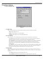
Device Options Tab .......................................................................................... 3-5
3.3.1
Ribbon Type............................................................................................ 3-5
3.3.2
Color Matching ........................................................................................ 3-5
3.3.3
Resin Dither ............................................................................................ 3-6
3.3.4
Print Both Sides ....................................................................................... 3-6
3.3.5
Split 1 Set of Ribbon Panels ..................................................................... 3-6
3.3.6
Print Back Side Only ................................................................................ 3-6
3.3.7
Rotate Front 180 Degrees ........................................................................ 3-6
3.3.8
Rotate Back 180 Degrees ........................................................................ 3-6
3.3.9
Disable Printing ....................................................................................... 3-6
3.3.10
Buffer Single Card ................................................................................... 3-6
3.4
Image Color Tab ............................................................................................... 3-7
3.5
Image Transfer Tab .......................................................................................... 3-8
3.5.1
Image Position......................................................................................... 3-8
3.5.2
Transfer Dwell Time and Temperature ...................................................... 3-9
3.5.3
Flattener Temperature ............................................................................. 3-9
3.6
K Panel Resin Tab .......................................................................................... 3-10
3.6.1
Defining an Area .................................................................................... 3-12
3.7
Magnetic Encoding ......................................................................................... 3-15
3.7.1
Overview............................................................................................... 3-15
3.7.2
Encoding Mode/ Coercivity/ Magnetic Track Selection.............................. 3-15
3.7.3
Magnetic Track Options ......................................................................... 3-16
3.7.4
Verification ............................................................................................ 3-16
3.7.5
Shift Data Left ....................................................................................... 3-16
3.7.6
ISO Track Locations .............................................................................. 3-16
3.7.7
Sending Track Information...................................................................... 3-17
3.8
Card Tab........................................................................................................ 3-19
3.8.1
Card Size.............................................................................................. 3-19
3.8.2
Card Type ............................................................................................. 3-19
3.8.3
Orientation ............................................................................................ 3-20
3.8.4
Copies .................................................................................................. 3-20
3.8.5
Test Print .............................................................................................. 3-20
3.8.6
About .................................................................................................... 3-20
3.9
Cleaning the Printer ........................................................................................ 3-20
3.9.1
Cleaning the Printhead........................................................................... 3-20
3.9.2
3.9.3
3.9.4
Cleaning the Platen Rollers .................................................................... 3-20
Clean the Inside of the Printer................................................................. 3-21
Clean the Cleaning Rollers ..................................................................... 3-21
PARTS REPLACEMENT .................................................................................................... 4-1
4.1
Removing the Covers........................................................................................ 4-3
4.1.1
Print Station Cover................................................................................... 4-3
4.1.2
Front Transfer Cover................................................................................ 4-3
4.1.3
Rear Transfer Cover ................................................................................ 4-3
4.1.4
Base Module Cover ................................................................................. 4-4
4.1.5
Card Input Hopper Cover ......................................................................... 4-4
4.1.6
Card Output Hopper Cover ....................................................................... 4-5
4.1.7
Back Cover ............................................................................................. 4-5
4.2
Replacing the Control Panel Assembly Components........................................... 4-6
4.3
Replacing the Printhead Assembly Components................................................. 4-7
4.3.1
Printhead (D840854)................................................................................ 4-7
4.3.2
Fan Assembly (840134) ........................................................................... 4-7
4.3.3
Head Force Spring (840272) .................................................................... 4-8
4.3.4
Ribbon Deflector (D840638) ..................................................................... 4-8
4.4
Replacing the Print Station Components ............................................................ 4-9
4.4.1
O-Rings (140212) .................................................................................... 4-9
4.4.2
Ribbon Sensor Board Assembly (140407) ............................................... 4-10
4.4.3
Encoder Wheel (810492)........................................................................ 4-10
4.4.4
Ribbon Sensor Array Assembly (840108) ................................................ 4-11
4.4.5
Ribbon Supply Motor Assembly (D840980) ............................................. 4-11
4.4.6
Ribbon Take-Up Motor Assembly (D840980) ........................................... 4-12
4.4.7
Headlift Motor Assembly (840131) .......................................................... 4-12
4.4.8
Ribbon Supply Encoder Sensor Assembly (D840982) .............................. 4-13
4.4.9
Headlift Sensor Assembly (D840983) ...................................................... 4-13
4.5
Replacing the Transfer Station Components..................................................... 4-14
4.5.1
Film Drive O-Rings (140212) .................................................................. 4-14
4.5.2
Encoder Wheel (810492)........................................................................ 4-14
4.5.3
Stepper Motor Assembly (840123) .......................................................... 4-15
4.5.4
Lamination Supply Encoder Sensor Assembly (840135)........................... 4-15
4.5.5
Lamination Take-Up Encoder Sensor Assembly (840136) ........................ 4-16
4.5.6
Lower Film Sensor Assembly (840199) ................................................... 4-16
4.5.7
Upper Film Sensor Assembly (D841023) ................................................. 4-17
4.5.8
Print Platen Roller (840319) ................................................................... 4-17
4.5.9
Transfer Peel Off Bar Assembly (840253) ............................................... 4-18
4.5.10
Ribbon Drive Hub (840324) .................................................................... 4-18
4.5.11
Transfer Station Assembly (840152) ....................................................... 4-19
4.5.12
Lamination Assembly (840159)............................................................... 4-20
4.5.13
Transfer Lift Switch (840142) .................................................................. 4-21
4.5.14
Transfer Lift Motor (840132) ................................................................... 4-21
4.6
Replacing Belt Driven Base Module Components ............................................. 4-23
4.6.1
Drive Belt – Platen Roller to Card Feed Roller (220071) ........................... 4-23
4.6.2
Drive Belt – Card Feed Roller to Card Feed Roller (220082) ..................... 4-23
4.6.3
Stepper Motor Assembly (840164) .......................................................... 4-24
4.6.4
Compound Grooved Pulley (8402328) .................................................... 4-25
4.6.5
Pinch Roller Spring Plate-Front (840354) ................................................ 4-25
4.6.6
Pinch Roller Spring Plate-Back (840354) ................................................. 4-26
4.6.7
Drive Belt – Tensioner to Platen Roller (F000003).................................... 4-26
4.6.8
Drive Belt – Stepper Motor to Tensioner (F000004).................................. 4-27
4.6.9
Main Pulley – Front (D850190) ............................................................... 4-27
4.6.10
Main Pulley – Back (D850190)................................................................ 4-28
4.6.11
Belt (F000018)....................................................................................... 4-29
4.6.12
Base Module (840151)........................................................................... 4-29
4.7
Replacing the Gear Driven Base Module Components ...................................... 4-31
4.7.1
Drive Belt – Platen Roller to Card Feed Roller (220071) ........................... 4-31
4.7.2
Drive Belt – Card Feed Roller to Card Feed Roller (220082) ..................... 4-31
4.7.3
Stepper Motor Assembly (840164) .......................................................... 4-32
4.7.4
Pinch Roller Spring Plate - Front Input Side (840354)............................... 4-33
4.7.5
Pinch Roller Spring Plate - Front Output Side (840354)............................ 4-33
4.7.6
Pinch Roller Spring Plate - Back Output Side (840354) ............................ 4-34
4.7.7
Pinch Roller Spring Plate – Back Input Side (840354) .............................. 4-34
4.7.8
Main Pulley (D850190)........................................................................... 4-35
4.7.9
Gear – Card Transport (760330) ............................................................. 4-35
4.7.10
Compound Gear (D841032) ................................................................... 4-36
4.7.11
Base Module (840151)........................................................................... 4-36
4.8
Replacing the Card Input Hopper Components ................................................. 4-38
4.8.1
Flipper Table Home Sensor Board Assembly (140407) ............................ 4-38
4.8.2
Card Low Sensor Board Assembly (140407) ........................................... 4-38
4.8.3
Card Feed Belt (220082)........................................................................ 4-39
4.8.4
Cleaning Roller Drive Idler Gear (760401) ............................................... 4-39
4.8.5
Card Feed Gear (810271) ...................................................................... 4-40
4.8.6
Encoding Feed Motor Assembly (840100) ............................................... 4-41
4.8.7
Cleaning Roller Assembly (840102) ........................................................ 4-42
4.8.8
Flipper Table Position Stepper Motor (840124) ........................................ 4-42
4.8.9
Card Feed Motor Assembly (840198) ...................................................... 4-42
4.8.10
Clutch Spring (840285) .......................................................................... 4-43
4.8.11
Card Sensor Assembly – Flipper Table (D840624)................................... 4-43
4.8.12
Card Feed Sensor (D840625)................................................................. 4-44
4.8.13
Magnetic Encoder Head (840104)........................................................... 4-44
4.8.14
Encoder Card Sensor (140407) .............................................................. 4-45
4.9
Replacing the Power Assembly Components.................................................... 4-46
4.9.1
Power Switch (120011) .......................................................................... 4-46
4.9.2
Power Cord Receptacle (130067) ........................................................... 4-46
4.9.3
Main Print Board (A000030) ................................................................... 4-47
4.9.4
Lamination Board (140402) .................................................................... 4-47
4.9.5
Power Supply (150240) .......................................................................... 4-48
4.10
Replacing the Output Stacker Components ...................................................... 4-48
4.10.1
Output Stacker (D840590)...................................................................... 4-48
4.10.2
Stacker Full Sensor (140407) ................................................................. 4-49
4.10.3
Stacker Lift Motor (840130) .................................................................... 4-49
PACKING YOUR HDP700 CARD PRINTER ........................................................................ 5-1
BOARD LEVEL DIAGNOSTICS .......................................................................................... 6-1
6.1
Board Errors ..................................................................................................... 6-1
6.1.1
EE Memory Error ..................................................................................... 6-1
6.1.2
EE Checksum Error ................................................................................. 6-1
6.1.3
DRAM Memory Error................................................................................ 6-1
6.1.4
RAM Memory Error.................................................................................. 6-1
6.1.5
FPGA...................................................................................................... 6-1
6.1.6
Update Firmware Now ............................................................................. 6-1
6.2
Sensor Testing ................................................................................................. 6-2
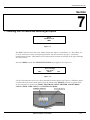
LCD ON-LINE MENU NAVIGATION.................................................................................... 7-1
7.1
Entering the LCD On-Line Menu and Selecting an Option ................................... 7-1
7.2
Print Test Image ............................................................................................... 7-3
7.3
Setup Printer .................................................................................................... 7-4
7.3.1
Preparing to adjust the Print Offset, Transfer TOF, and Transfer EOF ......... 7-4
7.3.2
Adjusting the Transfer Tension ................................................................. 7-5
7.3.2
Aligning the Print Offset ............................................................................ 7-5
7.3.3
Setting the Transfer TOF.......................................................................... 7-6
7.3.4
Setting the Transfer EOF.......................................................................... 7-7
7.3.5
Adjusting the Film Drive ........................................................................... 7-8
7.3.6
Adjusting the Ribbon Tension ................................................................... 7-8
7.3.7
Adjusting the Ribbon Drive ....................................................................... 7-8
7.3.8
Adjusting the Transfer Temperature.......................................................... 7-8
7.3.9
Setting the Flattener Temperature............................................................. 7-8
7.3.20
Setting the Printhead Resistance .............................................................. 7-9
7.3.21
Adjusting the Image Darkness .................................................................. 7-9
7.3.22
Changing the Encoder Settings ................................................................ 7-9
7.3.23
Setting the Magnetic TOF....................................................................... 7-10
7.3.15
Adjusting the Flipper Offset .................................................................... 7-11
7.3
Show Error Count ........................................................................................... 7-11
7.4
Show Card Count ........................................................................................... 7-11
7.5
System Upgrade ............................................................................................. 7-12
FIRMWARE UPDATES ..................................................................................................... A-1
A.1 - The Firmware Updater Application Program .......................................................... A-1
A.2 - Downloading Firmware Updates ........................................................................... A-1
A.3 - Updating Your Printer's Firmware ......................................................................... A-2
A.3.1
To update the Main Firmware: ................................................................. A-2
A.3.2
To update the LCD Firmware: .................................................................. A-3
FARGO Electronics Inc.
Section
1
Specifications
Regulatory Compliances
FCC
The Card Printer complies with the requirements in Part 15 of the FCC rules for a Class B
digital device. These requirements are designed to provide reasonable protection against harmful
interference in a residential installation. If, however, operation of this equipment in a residential
area causes unacceptable interference to radio and TV reception, the operator is required to take
whatever steps are necessary to correct the interference.
UL
The Card Printer is listed under UL 1950 INFORMATION TECHNOLOGY EQUIPMENT.
File Number
E145118, Volume 1, Section 15.
CSA
The printer manufacturer has been authorized by UL to represent the Card Printer as CSA
Certified under CSA Standard 22.2.
File Number
E145118.
TÜV-GS
The Card Printer has been tested and complies with IEC950 and bears the TÜV-GS mark.
License Number
S9971826.
ITS-EMC
The Card Printer has been tested and complies with EN55022 Class B: 1995 and EN70082-1:
1997 standards for EMI emissions.
License Number
J99032510.
Based on the above testing, the printer manufacturer certifies that the Card Printer complies
with all current EMC directives of the European Community and has placed the CE mark on the
Card Printer.
HDP700 Series Card Printer
1-1
FARGO Electronics Inc.
Agency Listings
Safety Standards
UL 1950, CSA C2.2 No.950-95 and TüV-GS (EN 60950 A1-A4, A11).
Emissions Standards
CE, FCC, CRC c1374, BSMI, ITS (EN 55022 Class B:1995, FCC Class B, EN 70082-1:1997).
Technical Specifications
Printing Method
HDP™ Dye-Sublimation/Resin Thermal Transfer.
Printing Resolution
300 dpi (11.8 dots/mm).
Colors
Up to 16.7 million colors and 256 shades per pixel.
Print Speed-Batch Mode
Approximately 35 seconds (YMC with transfer).
Approximately 41 seconds (YMCK with transfer).
Approximately 60 seconds (HDP720, dual-sided YMCKK with transfer).
Accepted Standard Card Size
CR-80: 3.375 in. x 2.125 in. (85.6mm x 54mm).
CR-90: 3.63 in. x 2.37 in. (92mm x 60mm).
CR-100: 3.88 in. x 2.63 in. (98.5mm x 67mm).
Print Area
Over-the-edge on all accepted standard card sizes.
Maximum Accepted Card Width Range
2.95 in. to 2.33 in. (54mm to 67mm).
Maximum Accepted Card Length Range
3.375 in. to 3.88 in. (85.6mm to 98.5mm).
Accepted Card Thickness
.030 in. (30 mil) to .060 in. (60 mil) (.762mm to 1.524mm).
Accepted Card Types
ABS, PVC, PET, PETG, proximity and smart cards.
Card Capacity
250 cards (30 mil); auto or manual feed.
Memory
8 MB RAM; expandable to 32 MB RAM.
Display
User-friendly, four-line LCD display with Soft key Control Pad.
Software Drivers
Windows 95/ 98/ ME/ NT/ 2000.
1-2
HDP700 Series Card Printer
FARGO Electronics Inc.
System Requirements
IBM-PC or compatible. Windows 95/ 98/ ME/ NT/ 2000. Pentium™ class 133 MHz computer with 32
MB of RAM or higher, 200 MB free hard disk space or higher, and ECP parallel port with DMA
access.
Interface
Centronics parallel, IEEE-1284 Compliant
Operating Temperature
65ºF to 80ºF (18ºC to 27ºC).
HDP Film Storage Temperature
77ºF (25ºC) or lower for no longer than 1.5 years.
Humidity
20% to 80% Non-Condensing.
Dimensions
14.3 in. H x 26.1 in. W x 14.3 in. D (363mm x 663mm x 363mm).
Weight
70 lbs. (31.8kg).
Supply Voltage
100 to 240 V ac.
Supply Frequency
50 Hz/60 Hz.
HDP700 Series Card Printer
1-3
FARGO Electronics Inc.
1-4
HDP700 Series Card Printer
FARGO Electronics Inc.
Section
2
General Troubleshooting
2.1 Contacting FARGO Technical Support
If you have read the suggested Sections of the Technical Service and Maintenance Manual and were unable to
find the answer(s) to your question(s), contact the FARGO Technical Support Group by phone at (952) 941-0050
or by fax at (952) 941-1852 for assistance.
Or, contact FARGO Technical Support via the Web:
http://www.fargo.com/tech_support/contact_tech_support.asp
Position a phone near the printer and computer so we can help troubleshoot the printer. Please have a self-test
and a sample card ready when you call FARGO Technical Support.
HDP700 Series Card Printer
2-1
FARGO Electronics Inc.
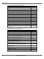
2.2 LCD Display Messages
The LCD display shows the current status of the printer. Please refer to the following tables for a complete list
and cause of all possible LCD messages. Note that these tables display the LCD messages in alphabetical order.
If the LCD message is communicating an error or requires an action, these tables will also offer a solution to
what should be done.
LCD Messages
Table 2-1
Message
Add Cards
Aligning Film
Aligning Ribbon
Card Jam
Card Jam: Flipper
Card Jam: Mag
Card Jam: Smart
Card Jam: Transfer
Cards Low
Data Input
Data Timeout
Door/Lever Unlocked
DRAM Memory Error
EE Checksum Error
EE Memory Error
Ejecting Used Card
Film Out
Film (upper)
Film (lower)
Film Sensing
Flipper Alignment
FPGA
FPGA Load Fail
FPGA Timeout
Head Lift
Head Resistance Error
Head Voltage Error
Initializing
Mag Encode Failed
Multiple Cards Fed
No ENC Response
No MAG Encoder
No SMART Encoder
Output Hopper Full
Pause...
Print Data
2-2
Cause / Solution
Indicates there is not an adequate supply of cards in the Card Input Hopper.
If this appears as a prompt, the HDP Film is self-aligning to the proper position for
printing. If this appears as an error see Section 2.7.1.
If this appears as a prompt, the print ribbon is self-aligning to the proper position for
printing. If this appears as an error see Section 2.6.1.
A card is jammed in the Transfer Station or card flipping area of the printer. See
Section 2.7.3.
A card is jammed in the card flipping area of the printer. See Section 2.4.3.
A card is jammed in the magnetic encoding area of the printer. See Section 2.5.4.
A card is jammed in the smart card encoding area of the printer. See Section 2.5.7.
A card is jammed in the Transfer Station of the printer. See Section 2.7.3
Indicates there is not an adequate supply of cards in the Card Input Hopper
The print data sent to the printer is corrupt or has been interrupted. Refer to Section
2.3.
The print data sent to the printer is corrupt or has been interrupted. Refer to Section
2.3.
You are trying to print with the Front Access Door open or the Release Lever in the
unlocked position. See Section 2.6.8.
The printer's memory module is bad or not installed properly. See Section 6.1.3
Permanent circuit board memory is bad. See Section 6.1.1.
Permanent circuit board memory is bad. See Section 6.1.2.
The system firmware has detected a card already in the printer and is ejecting it.
The HDP Film has run out. Install new Film, and press RESUME to continue.
The HDP Film is not installed properly, or has run out, jammed, broken, or been
damaged. See Section 2.7.1.
The printer was unable to sense the HDP Film properly while printing. See Section
2.7.1.
Unable to align flipper. See Section 2.4.4.
An unexpected hardware error has occurred. See Section 6.1.5.
An unexpected hardware error has occurred. See Section 6.1.5.
An unexpected hardware error has occurred. See Section 6.1.5.
The printer was unable to raise or lower the Printhead. See Section 2.6.5.
Please enter a value for head resistance in the LCD Printer Setup menu. See Section
7.3.20.
A hardware fault has prevented setting the correct Printhead voltage. See Section
7.3.20.
Indicates the printer is beginning its startup system check.
The magnetic stripe was not encoded properly. See Section 2.5.3.
Two or more cards fed from the Card Hopper. See Section 2.4.1.
There is no response from the encoder control module. See Section 2.5.1.
You are trying to send encoding data, but the printer is not configured with this
encoder type. See Section 2.5.2.
You are trying to send encoding data, but the printer is not configured with this
encoder type. See Section 2.5.6.
The output stacker is full of cards; empty the output stacker to avoid a jam.
Indicates the printer is paused.
The print data sent to the printer is corrupt or has been interrupted. Refer to Section
HDP700 Series Card Printer
FARGO Electronics Inc.
Print Ribbon
Print Ribbon Out
Print Timeout
Printer Open
Program Exception
RAM Memory Error
Realigning Film
Smart Encode Failed
Starting Self-test
Printhead Temp
Temperature Timeout
Testing Memory
Transfer Cooling
Transfer Lift
Transfer Timeout
Transfer Warming
Unable To Feed Card
Update Firmware Now
Wrong Print Ribbon
2.3
The print ribbon is not installed properly, or has run out, jammed, broken, or been
damaged. See Section 2.6.3.
The print ribbon has run out.
The printer was unable to complete the print process. See Section 2.3.
You are trying to print with the Print and/or Transfer Station open. See Section 2.6.8.
The system firmware has detected an error while attempting to process the current
print job. See Section 2.3.
The printer's memory module is bad or not installed properly. See Section 6.1.4.
Indicates the printer is aligning the HDP Film to the proper position for printing.
Usually occurs after the printer has finished a print job.
The card's smart chip was not encoded properly. See Section 2.5.6.
Indicates the self-test print is preparing to print.
The Printhead temperature regulator is not functioning properly. See Section 2.6.7.
The Transfer Roller is unable to reach the optimum temperature. See Section 2.7.4.
Indicates the printer's memory is being tested.
The printer's Transfer Roller is cooling to the proper temperature. See Section 2.7.2.
The printer was unable to raise or lower the transfer roller. See Section 2.7.5.
The printer was unable to complete image transfer. See Section 2.7
The Transfer Roller is warming to the proper temperature. See Section 2.7.2
The printer is unable to feed a card from the Card Hopper. See Section 2.4.1
The system firmware MUST be updated. See Section 7.5.
The print ribbon installed in the printer does not match the ribbon type selected in the
printer driver. See Section 2.6.4
SmartGuard™ Error / Status Messages
These messages only apply if you are using the printer's optional SmartGuard Security Feature.
Table 2-2
Message
Cause / Solution
Access Card Deleted
The data on the SmartGuard Access Card was successfully deleted. Press the OK
button to continue.
The SmartGuard data has successfully been encoded onto the SmartGuard Access
Card. Press the OK button to continue.
To delete the SmartGuard Access Card data, press the YES button. To cancel the
deletion process, press the NO button.
You are trying to print without the SmartGuard Access Card inserted. Insert a valid
SmartGuard Access Card.
To duplicate the SmartGuard Access Card, remove the valid access card, and insert a
blank access card. Then, press the COPY button to complete duplication or press
CANCEL to cancel duplication.
The SmartGuard Access Card is invalid or is inserted backwards or up side down.
Insert a valid SmartGuard card or reinsert the card properly with the chip end down
and facing you.
You have entered an invalid SmartGuard password. Re-enter the correct password
using any of the standard keyboard characters.
Indicates the printer is reading the data from the SmartGuard Access Card.
The SmartGuard Security Feature has successfully been disabled. You no longer need
to insert an access card to operate the printer. Press the OK button to continue.
All data has successfully been encoded onto the SmartGuard Access Card. The
SmartGuard Security Feature now protects the printer. From now on, you must insert
a valid access card to operate the printer. Press the OK button to continue.
Indicates the SmartGuard Access Card is being encoded.
Access Card Ready
Delete Card Data?
Insert Access Card
Insert New Card
Invalid Access Card
Invalid Password
Reading Access Card
SmartGuard Disabled
SmartGuard Enabled
Writing Access Card
HDP700 Series Card Printer
2-3
FARGO Electronics Inc.
2.3 Communication Errors
Symptom(s): Incorrect output, communications error on PC or printer, stalling, no response from
printer, no job printed, “paper out” error.
2.3.1 System does not meet requirements.
Confirm that the system meets the minimum requirements.
•
IBM-PC or compatible.
•
Windows 95/98/ME/NT/2000
•
Pentium™ class 133 MHz computer with 32 MB of RAM or higher.
•
200 MB free hard disk space or higher.
•
ECP parallel port with DMA access.
2.3.2 A driver or application is conflicting with the FARGO driver.
Close the software program and check the printer driver. Reboot the computer. Make sure the printer
driver is installed correctly. (Especially if an obsolete driver was recently removed.) Be sure the correct
setup options within the printer driver are selected. Confirm that the driver is current by checking at
www.fargo.com.
2.3.3 Using an inadequate data cable.
Use a double-shielded parallel cable, no longer than six feet in length. Data transmission failure can
be attributed to a long or faulty parallel cable. Radio frequency interference (RFI) may be the cause if
black resin text appears smeared (or is too dark), colors are misregistered, or the output is garbled. A
double-shielded, I-EEE 1284 compliant cable will reduce the effect of radio emissions from computers,
monitors, and other equipment that may broadcast RFI.
2.3.4 Interference from external device.
Do not use an A/B switch box or other peripheral in line with the parallel cable. If using a switch box
or other peripheral, remove it while testing communication between the computer and the printer. If
needed, replace it once the cause of the interference is determined not to be the switch box or
peripheral. Alternatively, a second parallel port may be added into the computer if a second printer is
required.
2.3.5 Cannot print from application.
•
Print a self test from the printer as described in Section 7.2 to ensure that the printer itself is
functioning properly.
•
Print the Windows test page that is located in the General tab of the driver.
•
Use WordPad (a Windows 95/ 98/ ME/ NT/ 2000 word processing program in the Accessories
Program Group). Open the program and type: “This is a Test.” then, go to File on the menu bar and
select Print.
2.3.6 Parallel port mode set incorrectly.
Ensure that the Parallel port is set to Enhanced Communication Port (ECP) mode. The port mode can
be determined by checking the Device Manager tab in the System Control panel. If the port mode is
not set to ECP, it will need to be changed in the computers BIOS. Refer to the computer manual for
instructions on how to change Parallel Port Mode.
2-4
HDP700 Series Card Printer
FARGO Electronics Inc.
2.3.7 Inadequate hard drive space.
A large amount of temporary files on your computer can cause communications errors. Temporary files
can be found by following these directions:
•
Search for all folders called “TEMP”. Once found, clear the contents of the folders.
•
If using Windows 95/98/ME/2000 run the system utility Disk Defragmenter found in the
Accessories folder of the Start Menu.
•
Use a disk cleanup utility such as Disk Cleanup found in the System Tools folder of the Start
menu, or a third party application.
HDP700 Series Card Printer
2-5
FARGO Electronics Inc.
2.4 Card Feed Errors
Symptom: Cards don’t feed from input hopper, cards jam in flipper or transfer Section, or LCD Errors.
2.4.1 Two or more cards are feeding at the same time or cards are not feeding properly
•
Remove the stack of cards. Ensure that the cards are not sticking together. Manually separate
them if needed. Remember not to touch the surface of the card. Dirt or oil from hands will impair
quality.
•
Slide the left wall of the Input Hopper to the proper location. The wall of the card hopper should be
within .030” (.75mm) of the stack of cards.
•
When loading cards, it is important that the Card Thickness Adjustment Knob be set accordingly
to ensure the printer feeds only one card at a time.
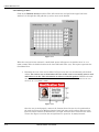
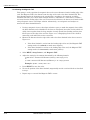
1. Open the Front Access Door.
2. Locate the Card Thickness Adjustment Knob.
3. Adjust this knob to the setting that matches
card thickness. See Figure 2-1. For fine scale
changes, see Adjusting the Card Separator
Flap in Section 3.1. The adjustment knob
controls the position of the printer's internal
Card Separator which is designed to
accommodate a range of card thickness
surrounding the given card thickness settings.
•
Figure 2-1
The Cleaning Rollers may be dirty or not
installed correctly. If the Cleaning Rollers are dirty or not installed correctly, the card may slip or
jam. Refer to Section 3.9.4 for instructions on how to clean the Cleaning Roller.
•
Inspect the Card Feed Roller Motors for proper operation. See Section 2.4.2
2.4.2 Card is stalling on or at the feed rollers
•
Use the arrows on the LCD panel to move the card forward or backward to free it.
•
Inspect the Card Feed Roller Motors for proper operation.
1.
Leave the power ON and open the Print and Transfer Stations.
2.
Press the FORWARD button to advance the card or the BACK button to reverse the card.
Use these buttons to move the card through the printer.
2.4.3 Card jamming on the Flipper Table
A card is jammed in the card flipping area of the printer. To clear the jam, see Section 2.7.3 for
information.
2.4.4 Printer is unable to align flipper
•
Open the Front Access Door and ensure that there are no obstructions.
•
Test the Flipper Table Home Sensor (140407) by entering the FLIPPER OFFSET in the PRINTER
SETUP menu on the LCD display. Without making any adjustment, press the SELECT button.
This should cause the Flipper Table to attempt to home itself.
•
Test the Flipper Table Home Sensor (140407) as described in Section 6.2. If sensor is not working,
replace as described in Section 4.8.11
2.4.5 Card feeds improperly off the Flipper table
Confirm that the Flipper Table Home Sensor is functioning as described in Section 2.4.4. If the Flipper
Table Home Sensor (140407) is functioning properly, adjust the FLIPPER OFFSET as described in
Section 7.3.24.
2-6
HDP700 Series Card Printer
FARGO Electronics Inc.
2.5 Encoding Errors
Symptom: No output encoded, unable to read encoded data on card, LCD error occurs.
2.5.1 No ENC Response
•
Ensure that the two wires to J62 on Lamination Board are properly seated. Check the wires to
ensure that they are plugged in properly.
•
The cable between the Print and Lamination Board may be bad. Replace the cable and see if the
error repeats itself.
•
The Lamination Board may be bad. Replace the Lamination Board as described in Section 4.9.4
and see if the error repeats itself.
2.5.2 No MAG Encoder
The printer is receiving encoding data, but the printer is not configured with this encoder type.
If this message appears and the printer is equipped with a Magnetic Encoder, refer to Section 7.3.22 to
change the encoder settings. If the encoding data was sent in error, check your software user’s manual
for encoding instructions.
2.5.3 Mag Encode Failed
The magnetic stripe was not encoded properly. Check to ensure that the cards are loaded with the
magnetic stripe facing down and towards the back of the printer. If cards are loaded properly, verify
your driver settings as described in Section 3.7.
2.5.4 Card Jam: Mag
A card is jammed in the magnetic encoding area of the printer. Clear the jam as described in Section
2.7.3. Ensure that the cards are feeding into the encoding module properly, if it is not, see Section 2.4.5
for instructions on how to adjust the flipper offset.
2.5.5 No SMART Encoder
The printer is receiving encoding data, but the printer is not configured with this encoder type.
If this message appears and the printer is equipped with a Smart Encoder, refer to Section 7.3.22 to
change the encoder settings. If the encoding data was sent in error, check your software user’s manual
for encoding instructions.
2.5.6 Smart Encode Failed
The card's smart chip was not encoded properly. Check to ensure that the cards are loaded with the
smart chip facing up and away from the Input Hopper Door.
2.5.7 Card Jam: Smart
A card is jammed in the smart card encoding area of the printer. Clear the jam as described in Section
2.7.3. Ensure that the card is feeding into the encoding module properly, if it is not; see Section 2.4.5
for instructions on how to adjust the flipper offset.
2.5.8 Unable to read encoded data
•
Check to ensure that the cards are loaded properly with the magnetic stripe facing down and
towards the back of the printer.
•
Check to ensure that the card is encoded with magnetic data by using a magnetic imager or
developer solution.
•
Use WordPad (a Windows 95/ 98/ ME/ NT/ 2000 word processing program in the Accessories
Program Group). Open the program and type: “~1%JULIEANDERSON^1234567890?” then, go to
File on the menu bar and select Print. The printer should then feed a card into the encoder and
magnetically encode it.
HDP700 Series Card Printer
2-7
FARGO Electronics Inc.
•
Ensure that the coercivity of the cards matches the setting in the driver.
•
Compare the settings for the card reader to the settings in the driver.
•
Ensure that the magnetic stripe on the card is free of scratches or voids.
2.5.9 Data intended for the magnetic stripe was printed on the card.
2-8
•
Confirm that the application is formatting the magnetic string correctly. See Section 3.7.7.
•
Use WordPad (a Windows 95/ 98/ ME/ NT/ 2000 word processing program in the Accessories
Program Group). Open the program and type: “~1%JULIEANDERSON^1234567890?” then, go to
File on the menu bar and select Print. The printer should then feed a card into the encoder and
magnetically encode it.
HDP700 Series Card Printer
FARGO Electronics Inc.
2.6 Printing Process Errors
2.6.1 Aligning Ribbon Error
•
Ensure that the ribbon is loaded properly and completely seated on the hubs.
•
Check to make sure the marks on the ribbon are complete.
•
Check motor operation by ensuring that the ribbon moves in both forward and backward directions
on power up.
•
Remove the back cover and locate the connector labeled J65 on the main board. Check the voltage
for each of the 5 ribbon sensors where they connect to the main board. With a multimeter, ground
the negative lead to the chassis and put the positive lead on pins 3, 5, 7, 9, and 11 of J65 on the
main board. Place a RibbonTraq™ mark over the ribbon sensor. The voltage should be less than 1
VDC. Remove the RibbonTraq mark from the ribbon sensor. The voltage should be greater than 4
VDC. Replace the sensor if the voltages are incorrect.
•
The Ribbon may be out, install a new ribbon, and press the RESUME button to continue.
•
The Ribbon may be jammed, clear the jam and reboot the printer.
•
The Ribbon may be broken, repair by taping the ribbon back on to the take-up core. Press the
RESUME button to continue or CANCEL to reset the printer.
2.6.2 Print Ribbon
The Print Ribbon is not installed properly, or has run out, jammed, broken, or been damaged. See the
remainder of Section 2.6 for details.
2.6.3 Print Ribbon Out
The Print Ribbon has run out. Install a new ribbon, and press RESUME to continue.
2.6.4 Wrong Print Ribbon
The Print Ribbon installed in the printer does not match the ribbon type selected in the printer driver.
Press RESUME to continue the print job, or press CANCEL to end the current print job and change
the Ribbon type in the driver as described in Section 3.3.1
2.6.5 Head Lift
The printer was unable to raise or lower the Printhead.
Press the RESUME button to retry. If the headlift does not rotate, check the Headlift Motor to ensure
that it is running. If the headlift motor is not running, replace the Headlift Motor as described in
Section 4.4.8. If the head cycles but does not stop at the position every time, check the Headlift Sensor
as described in Section 6.2. If the headlift sensor is failing, replace as described in Section 4.4.9.
2.6.6 Printer pausing between panels
•
The Printhead Fan is not operating properly. Confirm that the fan operates correctly. Upon power
up, the fan should run momentarily and shut off. Verify that the fan is plugged into the Main Print
Board properly on J67.
•
Check the Printhead fans for pinched wires. Inspect the wires that are routed under the top cover
and through to the back of the board to ensure that they are not pinched.
•
The thermal regulator on the Printhead may have failed. Remove the Printhead and reseat cable
connections. If problem persists, replace with a new Printhead as described in Section 4.3.1.
•
Data may not be received by the printer at the speed that it requires. See Section 2.3.
Note:
The Printhead Fan will run backwards if it is plugged in backwards. This will prevent proper cooling of the
Printhead.
HDP700 Series Card Printer
2-9
FARGO Electronics Inc.
2.6.7 Printhead Temp
The Printhead temperature regulator is not functioning properly.
•
Reboot the printer. If the problem persists, remove the Printhead and ensure that the Printhead
Cables are seated properly. If necessary, the back cover may need to be removed to verify the
Printhead Cable connection to the Main Print Board.
•
If after checking the Printhead Cable connection at both the Printhead and the Main Print Board,
(the error is still displayed on startup) replace the Printhead as described in Section 4.3.1.
•
Confirm that the cooling fan above the Printhead is operating properly. Upon power up, the fan
should run momentarily and shut off. If problem persists, install a new Printhead. If problem still
remains, replace the Main Print Board. See Section 4.9.3 for instructions.
2.6.8 Printer Open
The printer is operating with the Print and/or Transfer Station open. Ensure that both the Print and
Transfer Stations are completely closed and that the release lever is secured.
If the Print and Transfer Stations are completely closed, check the sensor (1404107) as described in
Section 6.2.
2-10
HDP700 Series Card Printer
FARGO Electronics Inc.
2.7 Transfer Process Errors
2.7.1 Transfer Film Drive Error
•
•
Lower Film Sensor may have failed. Check the voltage for the Film Sensor where it connects to the
Lamination Board.
1.
Place a Film mark over the Film Sensor. The voltage should be less than 1 VDC.
2.
Remove the Film mark from the Film Sensor. The voltage should be greater than 4 VDC.
3.
Replace the sensor if the voltages are incorrect.
Upper Film Sensor may be out of calibration. Calibrate the sensor as described below.
1.
Position the Transfer Film so that the clear portion is between the slotted optical sensor.
2.
Turn the potentiometer on the sensor board with a small slotted screwdriver until the LED
on the board turns on.
3.
Back the potentiometer off until the LED just turns off
•
A wire may be broken off of the motor. There are two motors that drive the Transfer Film. Verify
that both motors are connected to J66 on the Lamination Board. Disconnect the motors; a 9 VDC
battery connected to the motor leads should make it turn. If the motors do turn, verify the wire
connections at the motor and replace or solder as needed.
•
The Print or Lamination Board may have failed. Replace the Print Board as described in Section
4.9.3. Replace the Lamination Board as described in Section 4.9.4.
2.7.2 Laminator Cooling Error
The LCD indicates a Laminator Cooling error for an extended period of time.
1.
Driver Settings may be too extreme. Run a self-test from the printer as described in Section
7.3. This will cause the Laminator to attempt to operate at the default temperature.
2.
Transfer Temp setting may be too high. Check the Transfer Temp setting in the LCD setup
menu to ensure that the setting matches the label on the back of the printer. If it does not,
follow the instructions in Section 7.3.8 to adjust the Transfer Temp setting.
3.
The Thermocouple may have failed. To check the Thermocouple, use a multimeter to check
the leads across the Thermocouple Control C111 on the Lamination Board. The voltage
should be equal to the desired temperature (degrees C) divided by 100 with an accuracy of +/10 degrees C. If the correct value is not retuned, the Thermocouple may need to be replaced.
4.
The Lamination Board may be bad. Replace the Lamination Board as described in Section
4.9.4.
2.7.3 Card Jam
•
•
Card may be blocked or restricted in the Transfer Station. To continue printing with the same card
1.
Start by leaving the power ON and opening the Print Station and Transfer Station.
2.
Press the FORWARD button to advance the card or the BACK button to reverse the card.
Try not to move the card too far from where it was just before the jam occurred. Once the jam
is cleared, close the printer, and press the RESUME button to resume printing.
Card may be blocked or restricted in the Transfer Station. To remove the jammed card from the
printer
1.
Start by leaving the power ON and opening the Print Station and Transfer Station.
2.
Use the FORWARD and BACK buttons to manually eject the card. Then, close the printer.
The LCD Display will then display a prompt to either press the RESUME button or the
CANCEL button.
HDP700 Series Card Printer
2-11
FARGO Electronics Inc.
3.
Press the CANCEL button to reboot the printer and cancel all jobs from the printer memory.
All current print jobs will be canceled and will need to be resent from the computer.
2.7.4 Temperature Timeout
•
Run a self-test as described in Section 7.2. If no error occurs, the settings in driver may be too high
or too low. See Section 3.5 for instructions of how to adjust the transfer settings.
•
The Transfer Roller is unable to reach the optimum temperature. Turn the printer OFF and ON to
reset, and try reprinting. If the problem persists, see Section 2.7.2 to test the Thermocouple.
2.7.5 Transfer Lift
The printer is unable to determine the placement of the Lamination Roller. Check to ensure that the
Transfer Lift Motor is running. Disconnect the motor from the Lamination Board. A 9 VDC battery
connected to the motors’ leads may be used for testing. If the motor does turn, replace the Transfer Lift
sensor as described in Section 4.5.13. If the motor does not turn, replace the Transfer Lift Motor as
described in Section 4.5.14.
2-12
HDP700 Series Card Printer
FARGO Electronics Inc.
2.8 Output Errors
2.8.1 Cards feed into the Output Stacker, but are not lifted up into place.
•
Check operation by resetting the printer and visually confirming that the stacker cycles on powerup.
•
Verify that the wires (840121) from the Output Stacker are connected properly and are well seated
in the wire harness.
•
Ensure that the Output Stacker is set to the correct card size. Slide the wall of the Output Stacker
to the correct card size.
•
Test the operation of the Stacker Lift Motor by disconnecting the cable connector, and connecting a
9V battery to the wires. If the motor does not turn, replace the motor. If the motor does turn, the
Lam Board may need to be replaced as described in Section 4.9.4
HDP700 Series Card Printer
2-13
FARGO Electronics Inc.
2.9 Diagnosing Image Problems
2.9.1 Pixel Failure
Symptom: A thin line or scratch travels the entire length of the card.
•
Check the card stock for scratches; replace the cards if necessary.
•
Examine the Printhead for visible damage.
•
Clean the Printhead as described in Section 3.9.1.
•
Clean the Cleaning Rollers as described in Section 3.9.4.
•
Clean the Platen Rollers as described in Section 3.9.2.
2.9.2 Card Surface Debris
Symptom: Prints have "spots" (white or colored voids) and/or dust on them.
2-14
•
Be sure the cards are clean and stored in a dust-free environment. Cards with embedded
contaminants in the surface should not be used.
•
Clean the inside of the printer as described in Section 3.9.3.
•
Clean the Cleaning Rollers as described in Section 3.9.4.
•
Clean the Platen Rollers as described in Section 3.9.2.
HDP700 Series Card Printer
FARGO Electronics Inc.
2.9.3 Incorrect Image Darkness
Symptom: Printed cards are too dark or too light.
•
Run a self test as described in Section 7.2. This will ensure that the issue is not with the driver
settings.
•
Adjust the Dye-Sub Intensity setting within the Image Color tab of the printer driver as
described in Section 3.4
•
Correct the Image Darkness as described in Section 7.3.21.
HDP700 Series Card Printer
2-15
FARGO Electronics Inc.
2.9.4 Ribbon Wrinkle
Symptom: Printed cards have off-colored lines or streaks on them.
2-16
•
Confirm that the printer is using the most current driver from http://www.fargo.com.
•
Reduce the Dye-Sub Intensity setting within the Image Color tab of the printer driver as
described in Section 3.4.
•
Reduce the Image Darkness as described in Section 7.3.21.
•
Adjust the Ribbon Tension as described in Section 7.3.6.
•
Adjust Printhead Bracket Adjustment Screws. These can be found on the backside of the
Printhead. See drawing D840854. Loosen both of the screws and adjust the bar slightly outward.
Tighten the screws and print a self-test.
•
Check the Printhead and Printhead Mounting Bracket for debris and burrs.
HDP700 Series Card Printer
FARGO Electronics Inc.
2.9.5 Excessive Resin Printing
Symptom: Black resin text and barcodes appear smeared or too thick.
•
Reduce the Resin Heat setting within the Image Color tab of the printer driver as described in
Section 3.4.
•
Reduce the Image Darkness as described in Section 7.3.21.
2.9.6 Incomplete Resin Printing
Symptom: Black resin text and barcodes appear faded or too light.
•
Increase the Resin Heat setting within the Image Color tab of the printer driver as described in
Section 3.4.
•
Increase the Image Darkness as described in Section 7.3.21.
HDP700 Series Card Printer
2-17
FARGO Electronics Inc.
2.9.7 HDP Film Wrinkle
Symptom: HDP Film is creased or wrinkled on the printed card.
Note
HDP Film wrinkle will appear clear, or look as though the entire image is wrinkled. Alternatively, ribbon
wrinkle will appear as assorted colors.
2-18
•
Align the edge of the HDP Film with the Transfer Station red alignment arrows to ensure the Film
is tracking properly.
•
Decrease the Transfer Temperature setting within the Image Transfer tab of the printer
driver as described in Section 3.2.2.
•
Decrease the Transfer Temperature through the LCD as described in Section 7.3.8.
•
Adjust Film Tension
1.
In increments of one, lower the Film Tension through the LCD Setup Menu and print a
card.
2.
If, after several adjustments, the film wrinkle appears worse return the Film Tension to the
original setting and adjust the Film Tension up in increments of one.
3.
If still no change after the fourth adjustment, having made changes to the Film Tension by
a total of 4 points, go back to the original Film Tension value.
4.
Lower the Film Drive by one and repeat steps 1-3 until the film wrinkle is alleviated.
HDP700 Series Card Printer
FARGO Electronics Inc.
2.9.8 Incomplete Transfer
Symptom: Printed image has ragged edges; HDP Film seems to have peeled off.
•
Increase the Transfer Temperature setting within the Image Transfer tab of the printer driver
as described in Section 3.2.2.
•
Increase the Transfer Temperature through the LCD as described in Section 7.3.8.
•
Ensure that the Lamination Roller makes uniform contact with the card. Confirm that the
Lamination Roller moves up and down freely and that the Thermocouple wire does not restrict
movement.
•
If incomplete transfer is limited to the leading edge, the Transfer Tension is set too high.
Decrease the Transfer Tension through the LCD as described in Section 7.3.2.
•
If incomplete transfer is limited to the trailing edge, the Transfer Tension is set too low. Increase
the Transfer Tension through the LCD as described in Section 7.3.2.
HDP700 Series Card Printer
2-19
FARGO Electronics Inc.
2.9.9 Image Placement
Symptom: Printing is cut off or is not centered on the card, or a white border appears.
2-20
•
Verify that the HDP Film spools are wound evenly. If the spools are wound unevenly, replace the
roll of HDP Film.
•
Align the edge of the HDP Film with the Transfer Station’s red alignment arrows manually to
ensure the Film is tracking properly.
•
Verify that the Ribbon and Film are properly seated on both sides. The hubs’ axels should rotate as
you rotate the spool. If not, replace the hubs as described in Section 4.5.11.
•
Verify that the Dancer Rollers spin freely by opening the top and middle modules and manually
spinning the Dancer Rollers.
•
Confirm that the correct Card Size option is selected in the printer driver setup. Improper card
size settings will place the image in the wrong area of the card.
•
Confirm that the card is feeding straight into the print Section; if it is not, check to ensure that the
Card Size Knob in the base module is set to the proper card size.
•
Confirm that the Flattener is not impeding the card by manually feeding a card into the printer
using the FORWARD and BACK buttons on the display. The card should move freely under the
Flattener. If the card is hitting the Flattener, adjust the height of the Flattener by loosening the
two screws that hold the Flattener.
•
Verify that the upper and middle modules are seated properly and are completely locked down.
HDP700 Series Card Printer
FARGO Electronics Inc.
•
Use the Image Position option within the Image Transfer tab of the printer driver as described
in Section 3.5.1 to precisely center the image.
•
Make sure that the Platen Roller is clean. If unsure, follow the procedure for cleaning the Platen
Roller in Section 3.9.2.
•
See Print Offset, Transfer Tension, Transfer TOF (Top of Form), and Transfer EOF (End
of Form) Alignment in Section 7.3 to adjust the printer through the LCD.
•
Verify that the Peel-Off Bar and the Ribbon Peel bar height is correct. From the front of the HDP
Card Printer, the Peel-Off Bar on the input side (see drawing 840159) should be flush with the
frame; the Ribbon Peel Bar on the output side should have a 3/16-in. (4.5mm) gap between the
frame and the Ribbon Peel Bar. To try and remedy the offset printing, raise the bar higher off of
the card 0.005 inches by loosening the screws for the Peel-Off Bar and carefully raising both sides
the same amount. The Peel-Off Bar assembly should be equidistant from the frame at both ends.
•
Adjust the Ribbon Tension by +1 and print a sample card. If symptoms appear better, continue
adjusting until image placement is correct. If symptoms appear worse, adjust the Ribbon
Tension by –1 and print a self-test. If this makes the image placement look better, continue
adjusting until image placement is correct.
•
Verify Platen Roller Drive Belts. The small belt is tensioned by a spring and the large belt should
be tensioned by hand to approximately the same tension as the short belt.
2.9.10 Poor Image Quality
Symptom: Photos on the cards look pixilated or grainy.
Good
•
Bad
Use high-resolution, 24-bit color images. Always capture an image at a 24-bit color setting, at 300
dpi, and at the same size at which it will be printed on the card whether capturing with a scanner
or digital camera. If a small or low-resolution image is stretched or "blown up", a pixilated or
grainy effect will occur when printing.
2.9.11 Image Washout on Film
Symptom: Image appears to not be completely printed on Film.
•
Verify that the upper and middle modules are seated properly and are completely locked down.
•
Remove the Printhead and reinstall. If problem persists, replace the Printhead
•
Printhead pressure may be too low. Check the Printhead path to ensure there are no obstructions
and that the springs and cam are in the proper location. The lobe of the cam should be in the up
position when not printing. See drawing 840160.
•
Increase Image Darkness by increments of five as described in Section 7.3.21
•
If printing with non-FARGO cards, try reprinting with FARGO cards.
HDP700 Series Card Printer
2-21
FARGO Electronics Inc.
2.9.12 Registration problem
Symptom: Colors are shifted slightly in the image creating colored edges or poor resolution.
•
Upper Film Sensor is not in calibration
1.
Position the HDP Film so that a clear portion is between the slotted optical sensor.
2.
Turn the potentiometer on the sensor board with a small slotted screwdriver until the LED
on the sensor board turns on.
3.
Back the potentiometer off until the LED just turns off
•
Printhead pressure is too high or too low. Remove the Printhead as described in Section 4.3.1 and
bend the two metal springs slightly toward the back of the upper module. Reinstall the Printhead
and print a test card. If registration does not get better, remove the Printhead and bend the two
metal springs away from the upper module slightly. Reinstall the Printhead and print a self-test.
•
Adjust the Ribbon Tension by +1 and print a sample card. If symptoms appear better, continue
adjusting until registration problems are gone. If symptoms appear worse, adjust the ribbon
tension by –1 and print a self-test. If symptoms appear better, continue adjusting until registration
problems are gone.
•
Loosen the screws that hold the Film Drive Motor located in the middle module and pull the motor
back against the belt. See drawing 840152. Hold the motor there and tighten the screws that hold
the motor in place in this new position.
2.9.13 Image Skewed on the Card
Symptom: The self-test image appears skewed on the card.
2-22
•
Film is tracking sideways. Open the lamination station and reload the Transfer Film so that Film
moves straight onto spool. In extreme cases, it may be beneficial to remove the old Film from the
take-up spool and reattach the Film in the proper location on the spool.
•
Peel-Off Bar is not straight. The Peel-Off Bar should be equidistant from the Lamination Assembly
frame at both ends. Adjust if necessary as described in Section 2.9.9.
•
The card may be fed into the Transfer Station askew. Interrupt the transfer process to ensure that
the card has fed properly into the Transfer Station. If the card has been fed skewed, ensure that
the card size knob is set to the correct card size. Once the card size has been confirmed, manually
feed a card into the printer using the FORWARD and BACK soft key buttons on the display.
Position the card next to the spring loaded Card Pusher and ensure that the Card Pusher is
applying pressure to the card.
HDP700 Series Card Printer
FARGO Electronics Inc.
Section
3
Printer Adjustments
This Section covers the replacement of key components of the card printer. Be sure to reverse the
disassembly steps to reassemble the card printer.
Safety Messages
Procedures and instructions in this Section may require special precautions to ensure the safety of the
personnel performing the operations. Information that raises potential safety issues is indicated by a
warning symbol (as shown below).
Refer to the following safety messages before performing an operation preceded by this symbol.
DANGER
Failure to follow these installation guidelines can result in death or serious injury. Always remove the power
cord prior to performing repair procedures, unless otherwise specified. Make sure only qualified personnel
perform these procedures.
Procedures and instructions in this Section may require special precautions to ensure the safety of the
personnel performing the operations. Information that raises potential electrostatic safety issues is indicated
by a warning symbol (as shown to the below).
Refer to the following safety messages before performing an operation preceded by this symbol.
CAUTION
This device is electrostatically sensitive. It may be damaged if exposed to static electricity discharges. Be sure
to observe all established electrostatic discharge (ESD) procedures while handling cables in or near the
Circuit Board and Printhead Assemblies. Always wear an appropriate personal grounding device, such as a
wrist strap with integral resistor, connected to an ESD ground to avoid potential damage.
IMPORTANT
Always remove the HDP Ribbon and Cards from the printer before making any repairs, unless otherwise
specified. Take jewelry off of fingers and hands and be sure to thoroughly cleanse hands to remove oil and
debris before working on the printer.
HDP700 Series Card Printer
3-1
FARGO Electronics Inc.
3.1 Fine-Tuning the Card Separator Adjustment Assembly
(D840995)
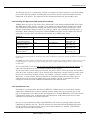
The height of the Card Input Guide may need to be fine-tuned to accommodate a specific card
thickness. The example given below describes adjusting the Card Input Guide for a 30-mil card.
Refer To Drawing 840156.
Tools Needed
.005 in. Feeler Gauge (Or a single sheet of paper)
Card (of appropriate thickness)
Place the card in the Card Input Hopper with the trailing edge of the card over the center line of the
outside Feed Roller.
1.
Position the Feeler Gauge (or sheet of paper) on top of the card and just under the Card
Separator.
2.
Locate the Card Thickness Adjustment Knob.
3.
Adjust this knob to the setting that most closely matches the thickness of your card.
4.
Locate the Card Separator Adjustment Assembly (840101).
5.
Move the Height Adjustment Thumb Screw up and down until the gauge just touches the
clear rubber.
•
If the gap above the card is too small, the card will not feed.
•
If the gap above the card is too large, multiple cards may feed.
NOTE
After completing this adjustment, be sure to test it. First, feed a card with a few cards in the hopper. Then,
place a full stack of cards in the Card Input Hopper and feed a few cards. Continue to adjust the Card
Separator Adjustment Assembly if needed.
®
™
™
3.2 Using FARGO High Definition Printing (HDP ) Technology to Print on Alternate Card
Stocks
3.2.1 Selecting the Right Cards and Optimizing the HDP Print Process
HDP technology has many advantages over direct-to-card printing where unique card materials and
card surfaces are concerned. In order to optimize the HDP Card Printer’s capabilities for customers
using cards with hard-to-print surfaces, we recommend you evaluate your customer’s card stock
selection BEFORE delivery of their printer, and consult with them to determine optimal printer driver
settings.
There is a great deal of variability in cards based on:
3-2
•
Different surface textures and different sources of raw materials – may require different HDP
Film transfer parameters.
•
Varied methods of assembling IC smart cards and proximity cards – particular adhesives used to
glue a smart chip to a plastic card may react differently to a lamination roller’s pressure and
temperature.
•
Cleanliness of card stock – The HDP process does not eliminate the need to use clean card stock.
The best-looking card always starts with the cleanest card surface. Dirt and debris on a card can
show up as blemishes on the card surface and may reduce the life of the image itself.
HDP700 Series Card Printer
FARGO Electronics Inc.
For all these reasons, it is important to evaluate a customer’s card stock selection as part of the selling
process. This will help optimize the HDP print process for the specific card and maximize customer
satisfaction in the printer. The remainder of this document describes how this should be done.
3.2.2 Selecting The Appropriate HDP Printer Driver Settings
FARGO offers two types of PVC cards: glossy UltraCard™ cards and matte-finished HDP-PVC Cards.
The HDP printer driver software (version 1.3.0 or higher) has default Transfer Temperature, Dwell
Time and Flattener Temperature settings that deliver the best transfer for these card types. These
defaults automatically configure based on the card type, ribbon type, and whether printing single- or
dual-sided. Before printing, if using these standard FARGO card types, check to make sure that the
appropriate card type option selected from the Card Tab of the HDP printer driver:
Table 3-1
Card/Ribbon Type
UltraCards-Glossy PVC
+ non-H panel ribbon
HDP Cards-Matte PVC +
non-H panel ribbon
UltraCards-Glossy PVC
+ H panel ribbon (2)
HDP Cards-Matte PVC +
H panel ribbon (2)
Transfer Temp
175º
Transfer Time
2 seconds/inch
195º
2 seconds/inch
175º
2 seconds/inch
175º
2 seconds/inch
Flattener Temp(1)
Dual Side: 75º
Single Side: 90º
Dual Side: 75º
Single Side: 90º
Dual Side: 75º
Single Side: 90º
Dual Side: 75º
Single Side: 90º
(1)
Based on 30-mil card thickness. For thinner cards, reduce the Flattener temperature; increase the Flattener temperature for
thicker cards.
(2)
YMCKH panel ribbon provides a "Heat Seal" panel that aids in transferring to matte-finished cards and requires a lower
transfer temperature. Note that only matte-finished cards with a surface roughness (Ra) of 60 micro inches or less are
recommended.
It is very important to note that not all card types will be accommodated by these default settings. In
some cases experimentation may be needed to find the proper settings.
For the cases where custom settings are required, the printer driver's Card Type option also includes a
"Custom 1" and "Custom 2" option. These settings allow designating a unique Card Type name, which
then saves custom Image Transfer settings. For example, "Custom 1" could b e changed to read as
"My Cards". Custom transfer settings would then be available whenever this Card Type option is
selected and saved each time the printer driver setup window is closed. To determine the proper
settings for custom card stock, FARGO recommends the Tape Adhesion Test.
3.2.3 Tape Adhesion Test
If printing to a card other than UltraCard or HDP-PVC, FARGO cannot be certain which transfer
temperature and dwell time work best. Optimal transfer settings may vary from card type to card
type. It is important to use sufficient time and temperature to transfer HDP Film to the card to ensure
a long lasting, durable card. Inadequate time and temperature could produce cards that are more
vulnerable to accelerated wear and dye migration.
One way to test the adhesion quality of the HDP Film to the card is by printing sample cards and
completing an adhesive tape test. The IPC (Institute for Interconnecting and Packaging Electronic
Circuits) outlines a pressure sensitive tape test (test manual Section 3.7, number 1, IPC-TM-6503.7.1D) that evaluates adhesion quality.
HDP700 Series Card Printer
3-3
FARGO Electronics Inc.
Begin by selecting either "UltraCards-Glossy PVC" (if the
card is glossy) or "HDP Cards-Matte PVC" (if the card has
a buff, matte finish), and print a test card.
Next, apply a strip of ½” (12mm) wide Scotch-type clear
adhesive tape (such as 3M brand 600), at least 2” (50mm)
long, firmly across the surface of the card, pressing out all
air bubbles with a fingertip. Remove the tape by smoothly
and rapidly (approximately 2 inches/second (50mm/sec))
pulling it up at a perpendicular, angle to the card. The IPC
recommends a minimum of three tests for each card type
evaluation.
Visually examine the card and the strip of tape pulled
from the card, to see if any portion of the HDP Film was
removed from the card. (If any residue such as oil or
grease from fingertips is present on the card surface, the
evaluation results may be affected.) If particles of the
printed, transferred HDP Film pull away from the card,
and adhere to the tape, this indicates inadequate adhesion
of the HDP Film to the card, and that increased heat and
dwell times are necessary. Samples 1, 2, and 3 show a
representation of the level of adhesion you should expect.
Sample 1 is an absolute failure and sample 3 is an
absolute pass. Sample 2 shows that very slight transfer to
the tape can be acceptable without sacrificing overall
image durability on matte finish cards.
If the tape test indicates inadequate adhesion, increase the
heat setting by 5 degrees, print another card, and try the
tape test again. Once the temperature has been increased
4 times (20 degrees), reset temperature to default and
increase the dwell time by .5 second. Repeat this until
adequate adhesion. Note that if you are printing to a
matte- surfaced card, it is advantageous to use FARGO's
YMCKH ribbon. This ribbon provides a "Heat Seal" panel
that allows for improved adhesion to non-glossy PVC
surfaces. For best results, be sure that the cards you are
using have a surface roughness (Ra) of 60 micro inches or
less. This information should be available from the card
manufacturer.
1
FAIL:
Significant
transfer to tape
2
PASS:
Very slight
transfer to tape
3
PASS:
Absolutely NO
transfer to tape
Figure 3-1
3-4
HDP700 Series Card Printer
FARGO Electronics Inc.
Printer Driver Options
3.3 Device Options Tab
Figure 3-2
3.3.1 Ribbon Type
Used to match the ribbon type selection with the ribbon type that is loaded in the printer.
YMC- Yellow, Magenta, Cyan
YMCK – Yellow, Magenta, Cyan, Resin Black
YMCKH- Yellow, Magenta, Cyan, Resin Black, Heat Seal
3.3.2 Color Matching
Allows selection of the Color Matching option that best fits the requirements of the print job.
Select None if interested in print speed rather than print color, if color correcting the image for
printing has already been done, or if using third party Color Matching software.
Select Algebraic to allow the printer driver to make very simple, fast, color balance adjustments.
This option gives a natural-looking image without slowing down the processing speed of the
printer driver. It also allows further customization of the printed color of the cards through the
Image Color tab.
Select Monitor to allow the printer driver to make color corrections similar to the Algebraic option
but through a more complex color matching algorithm. This option shifts colors more radically so
the colors in the image will more closely match how they appear on screen.
3.3.3 Resin Dither
This option only affects those objects printed on the backside of a card with the resin black panel of a
YMCK or YMCKK print ribbon. Select the appropriate dither method according to the type of image to
be printed.
Select Photo if printing photo quality images with resin.
Select Graphics if printing lower quality images (i.e. clipart, logos, etc.) with resin.
HDP700 Series Card Printer
3-5
FARGO Electronics Inc.
3.3.4 Print Both Sides (HDP720 only)
Select this option to automatically print on both the front and backside of a card. This option can be
selected in conjunction with any application program that supports a multiple-page document, duplex
printing. In other words, the program must be able to send down two or more separate pages to be
printed within the same document.
For example, to print a full-color ID format on the front of the card and monochrome text or bar codes
on the back, simply create the full-color front side of the card on page 1 of the document and the
monochrome back side on page 2. The printer driver will always place all odd numbered pages on the
front side of the card and all even numbered pages on the back side.
3.3.5 Split 1 Set of Ribbon Panels (HDP720 only)
Select this option to automatically print full-color on the front of a card and resin black on the back of
a card using either of the Full-Color YMCK or YMCKK print ribbons. Selecting this option provides
the most economical means of printing a dual-sided card since a single set of ribbon panels is
essentially "split" to print both the front and backsides of a card. If using a YMCK ribbon type, the
front of the card is printed with the ribbon's YMC panels and the back is printed with the K panel. If
using a YMCKK ribbon type, the front of the card is printed with the YMCK panels and the back is
printed with the second K panel. Note that this option is automatically enabled when the YMCKK
ribbon type is selected. Also, note that the Print Both Sides option is automatically enabled when this
option is selected.
3.3.6 Print Back Side Only (HDP720 only)
Select this option to print only onto the backside of a card. This option allows for conveniently printing
the backside of preprinted cards that also must have their magnetic stripe or smart card chip encoded.
Be sure to load cards in the usual fashion. Note that when this option is selected, the Print Both Sides
option is automatically disabled.
Note
When attempting to print a two-page document, if Print Back Side Only is selected, the first page of the
document will print on the backside of the card. The second page of the document will then be printed
on the back of a second card.
3.3.7 Rotate Front 180 Degrees
This option rotates the image on the front of the card 180 degrees when printed. This option is often
used to change the position of the printed image in relation to the set location of a card's magnetic
stripe or smart chip.
3.3.8 Rotate Back 180 Degrees (HDP720 only)
This option rotates the image on the back of the card 180 degrees when printed. This option is often
used to change the position of the printed image in relation to the set location of a card's magnetic
stripe or smart chip.
3.3.9 Disable Printing
Selecting this option disables the printing capabilities of the printer, yet still allows the printer to
encode cards. This option is useful to encode or re-encode preprinted cards without wasting additional
time, effort, or printing supplies. When this option is selected, no print data will be sent to the printer,
while all encoding instructions will be sent according to how they are configured within the software.
3.3.10 Buffer Single Card
Select this option to force the printer's memory to buffer, or hold, only one print job at a time. This
option should be selected only if printing to multiple printers sharing print jobs over a
network. In this case, this option ensures all printers evenly share all print jobs. When this option is
not selected, the printer's memory will buffer as many print jobs as it can until the printer's memory is
full. This is ideal for most applications where printers are not networked together.
3-6
HDP700 Series Card Printer
FARGO Electronics Inc.
3.4 Image Color Tab
Figure 3-3
When the Algebraic color matching option is selected, this option allows control of the Contrast and
Gamma of the printed image, as well as the individual color balance of Yellow, Magenta, and Cyan.
See Figure 3-3. When the None or Monitor option is selected, only the Dye-Sub Intensity and Resin
Heat sliders will display.
To control the overall darkness and lightness of the dye-sub printed image, adjust the Dye-Sub
Intensity slide by clicking and dragging the slide's box. Moving the slide to the left causes less heat to
be used in the printing process, thus generating a lighter print. Moving the slide to the right causes
more heat to be used, thus generating a darker print. This slide only affects those images printed with
dye-sublimation ribbon panels (YMC).
To control the amount of heat the printer uses when printing with the resin black panel, adjust the
Resin Heat slide. Moving the slide to the left causes less heat to be used in the printing process,
causing resin images to be lighter or less saturated. Moving the slide to the right causes more heat to
be used, causing resin images to be darker or more saturated. This control can be helpful for finetuning the sharpness of resin text and bar codes.
To return all options to their factory settings, click on the Default button.
HDP700 Series Card Printer
3-7
FARGO Electronics Inc.
3.5 Image Transfer Tab
Figure 3-4
3.5.1 Image Position
The Image Position controls allow the position of the image on a card to be adjusted. To adjust the
Image Position values, click on the Vertical and Horizontal adjustment arrows. When adjusting these
values, keep in mind that cards always remain in the same position as they travel through the printer,
regardless of image orientation. The Card Illustration shown in the Image Position box will flip and
rotate according to selection of Portrait, Landscape, or Rotate 180 Degrees. See Figure 3-5. Note, the
outline around the illustration will always remain in the same landscape orientation.
Figure 3-5
Figure 3-6 represents how the printed image will move in relation to the fixed card position as positive
and negative image placement values are entered.
3-8
HDP700 Series Card Printer
FARGO Electronics Inc.
Figure 3-6
The Vertical adjustment moves the image toward the rear of the printer if a positive number is
entered and toward the front of the printer if a negative number is entered. The Horizontal
adjustment moves the image toward the card output side of the printer if a positive number is entered
and toward the card input side of the printer if a negative number is entered. The maximum value for
the Vertical and Horizontal adjustments is ±100 pixels (10 pixels = 0.03" (.8mm)).
3.5.2 Transfer Dwell Time and Temperature
The Image Transfer option also allows control of the Transfer Dwell Time and Transfer
Temperature. See Figure 3-4. These settings control the speed and temperature at which printed
images are transferred from the HDP Film to the card. Depending on the card type, these settings may
vary. The printer driver automatically optimizes these settings according to the selection made in the
Card Type option. Any changes made to the dwell time and temperature settings will be saved for the
selected Card Type option upon exiting the printer driver setup in the printers control panel. To
return to the factory default settings for the selected Card Type, click on the Default button. See
Figure 3-4.
If using cards that differ from the Card Type Glossy-PVC or Matte-PVC options, select one of the
Card Type Custom options, then adjust the dwell time and temperature settings manually to ensure
proper image transfer.
To determine the appropriate settings for the card stock, set the Transfer Dwell Time and Transfer
Temperature to the default settings. Then, print a card. If the HDP Film is not transferring properly,
adjust these settings accordingly. Once the Film is transferring properly, perform a final durability
test called the "Tape Test." For instructions on how to do a tape test, see Section 3.2.3.
3.5.3 Flattener Temperature
The Flattener Temperature control sets the temperature of the printer's built-in Card Flattener.
Depending on the card type, this setting may vary. If using the standard UltraCard-Glossy or HDP
Card-Matte PVC Card Type option, the printer driver automatically optimizes this setting according to
whether printing single or dual-sided cards. In general, single-sided prints require a hotter Flattener
temperature. If using another type of card stock, it may be necessary to adjust this setting to optimize
the flatness of the cards. Any changes made to the Flattener temperature will be saved upon exiting
the printer driver setup. To return to the factory default setting, simply click on the Default button.
See Figure 3-4.
HDP700 Series Card Printer
3-9
FARGO Electronics Inc.
3.6 K Panel Resin Tab
Figure 3-7
This option controls where the resin black (K) panel of a full-color ribbon is printed. Note that if
printing with a ribbon type that does not have a K panel, such as the YMC ribbon type, all K Panel
Resin options will be grayed out. Resin black text is desirable due to its sharp, saturated color, and
resin black barcodes are required to ensure readability when scanned by an infrared barcode reader.
The printer driver will automatically print all TrueType black text and TrueType barcodes only with
the resin black (K) panel of the print ribbon by default.
If printing black text or barcodes that are not TrueType fonts or black graphics, select one of the three
options listed under "Print All Black With K Panel." See Figure 3-7. The printer driver will print
areas of the image where it finds black coloring with the print ribbon's resin black (K) panel as
specified by each of the following options:
1.
Select the Full Card option to print the resin black (K) panel for all black found within all
areas of the image. See Figure 3-8.
Figure 3-8
3-10
HDP700 Series Card Printer
FARGO Electronics Inc.
2.
Select the Defined Area(s) option to print the resin black (K) panel for all black found only
in an area or areas defined. See Figure 3-9.
Figure 3-9
3.
Select the Undefined Area(s) option to print the resin black (K) panel for all black found
only in the space outside the areas defined. See Figure 3-10.
Figure 3-10
HDP700 Series Card Printer
3-11
FARGO Electronics Inc.
3.6.1 Defining an Area
Click on the Defined Area(s) check box. This will activate the card grid in the upper half of the
window. It is through this card grid that up to five areas can be defined.
Figure 3-11
When the card grid is first activated, a small black square will appear at its default size of .2" x .2"
(5mm x 5mm) and at its default location in the lower left-hand corner (0,0). This square represents the
first defined area.
1.
Determine the area of the card to define. In Figure 3-12, this area is indicated by the dashed
outline. The easiest way to determine the size of this area is to actually print a card,
and look at it in the same orientation as when it exits the printer. Measure the total
area, and enter those dimensions into the dimension boxes. Note the minimum size an area
can be is .2" x .2" (5mm x 5mm).
Figure 3-12
Once the area is sized properly, measure the location where this area is to be positioned on
the card. See Figure 3-13. Measure from the lower left corner of the card up and over to the
lower left corner of where the defined area is to begin, and enter these values into the X and
Y boxes. See Figure 3-14. Note the card grid lines are spaced at .2” (5mm) intervals.
3-12
HDP700 Series Card Printer
FARGO Electronics Inc.
Figure 3-13
Figure 3-14
To define another area, click on the Defined Area up arrow. Another .2" x .2" (5mm x 5mm)
area will appear in the lower left-hand corner. See Figure 3-15. This is the location in which
all newly defined areas will first appear. Up to 5 areas can be defined. Additional areas
cannot be added until the most recently created area has been moved or sized. For this
reason, size and position each area as it is created. Use the Defined Area arrows to navigate
back and forth from area to area. The active area will always be highlighted with a dotted
outline. To delete an area, use the Defined Area arrows to select the area, and click on the
Delete button. If all areas are deleted, the K Panel Resin options will automatically be
deselected.
HDP700 Series Card Printer
3-13
FARGO Electronics Inc.
Figure 3-15
Select between the Print YMC Under K and Print K Only options. See Figure 3-15. When the Print
YMC Under K option is selected, all black in the designated areas will print with the Yellow (Y),
Magenta (M), and Cyan (C) ribbon panels directly beneath the resin black (K) panel. Select this option
if printing resin black text or barcodes onto a colored background to provide a more gradual transition
between the two.
When the Print K Only option is selected, all black in the designated areas will print only with the
resin black (K) panel. Select this option if printing resin black onto a white background to maximize
the sharpness of printed text and barcodes.
3-14
HDP700 Series Card Printer
FARGO Electronics Inc.
3.7 Magnetic Encoding Tab
Figure 3-16
These options only apply if the printer has an optional Magnetic Stripe Encoding Module installed.
Select this tab to display options for controlling the magnetic stripe encoding process. The following
describes these options and the printer's magnetic encoding process.
3.7.1 Overview
The HDP Card Printer can be purchased with one of two types of factory-installed Magnetic Stripe
Encoding Modules. The first, most common type is an ISO Standard encoding module with a dualcoercivity (high or low) encoding head. The second is a JIS II Standard encoding module commonly
used in Japan.
By default, the printer driver is set to encode according to ISO standards onto high-coercivity magnetic
stripes. To change the encoding mode, coercivity setting, or to modify the ISO standards for tracks 1, 2,
and 3, modify the following Magnetic Encoding options accordingly.
3.7.2 Encoding Mode / Coercivity / Magnetic Track Selection
The ISO option provides encoding capability for either high- or low-coercivity cards on tracks 1, 2, and
3 and is the industry's standard mode of magnetic encoding. Use the Coercivity option to select the
type of magnetic stripe that matches your card type.
•
High Coercivity = 2750-4000 Oersted (FARGO’s High Coercivity UltraCards are 2750Oe)
•
Low Coercivity = 300 Oersted
If the application being used requires customization of the standard ISO encoding process, use the
Magnetic Track Selection option to specify which track is to be configured through the Magnetic
Track Options.
Although the default ISO Magnetic Track Options should be correct for most applications, these
options can be customized if the application requires it. Please note that all options must be changed
separately for each of the three individual tracks. To set these options back to the ISO standard
HDP700 Series Card Printer
3-15
FARGO Electronics Inc.
settings once they have been changed, simply select the Default button for each of the separate
tracks.
Use the Encoding Mode option to specify which magnetic encoding standard to use. The JIS II option
provides encoding compatibility with the JIS C 6220 Type II cards commonly used in Japan. When the
JIS II mode is selected, only track 2 will be encoded. Note that no encoding customization options are
available with the JIS II mode.
Note:
A JIS II Magnetic Head must be installed in the printer to use any of the JIS II options in the driver.
3.7.3 Magnetic Track Options
Use these options to customize the ISO encoded data format for each of the magnetic stripe's three
tracks. Remember that each track must be customized independently of the other two. Specify which
of the three tracks to customize by selecting one of the three track options. After making the required
selection, the Magnetic Track Options box displays the current set of customization options for the
selected track.
3.7.4 Verification
This option instructs the printer to verify that all magnetic data has been correctly encoded on each
card. If the Auto Eject 1st Error option is selected, the printer will automatically eject a card
containing magnetic data that cannot be verified. Only the first misverified card will be automatically
ejected. If a second consecutive card cannot be verified, the printer will signal an error and go into
manual eject mode. The auto eject option is the most direct means of dealing with misverified cards,
but may be undesirable if batch printing since misverified blank cards are ejected into the same stack
as verified printed cards. For this reason, a Manual Eject Each Error option is also provided. When
this option is selected, the printer will signal an error on its LCD display stating that the magnetic
data could not be verified. When this occurs, press the CANCEL soft key to manually eject the
misverified card.
With either of these options, the number of verification retries may be specified. A range of 1-5 retries
is available. This option is helpful since magnetic stripe verification can sometimes require more than
a single pass.
3.7.5 Shift Data Left
The Shift Data Left option is applied to all tracks when selected. This option shifts the recorded
magnetic data to the left-hand side of the card's magnetic stripe. This is useful in situations that
require cards to be readable with insert type readers
3.7.6 ISO Track Locations
The magnetic encoding module encodes onto tracks in accordance with an ISO 7811-2 magnetic stripe.
See Figure 3-17 for track locations.
Figure 3-17
3-16
HDP700 Series Card Printer
FARGO Electronics Inc.
3.7.7 Sending Track Information
Magnetic track data is sent in the form of text strings from the application software to the printer
driver. In order for the printer driver to differentiate between magnetic track data and the rest of the
printable objects, specific characters must be added to the magnetic data to be encoded. These specify
the data that is to be encoded, the tracks to encode, and mark the start and stop of the data string. In
some cases, these specific characters are automatically added to the string of track data by ID software
applications. In most cases, the user must manually add these characters to the string of magnetic
track data. If these characters are not added to the track data, the text intended for the magnetic track
will appear as printed text on the card. To avoid this, track information must be entered as follows.
When entering track data, the "~" (tilde) character is entered first, followed by the track number (1, 2,
or 3) on which the data should encode. This is followed by the data to be encoded. The first character of
this data string must be the track's specific Start Sentinel (SS) and the last character must be the
specific End Sentinel (ES). The characters or data in between the SS and ES can include all of the
valid characters specific to each track. The number of these characters, however, is limited by each
track's maximum character capacity. When segmenting track data, the appropriate Field Separator
(FS) must be used. Table 3-3 shows the SS, ES, FS, and the valid characters defined for each track.
Sample String
Track 1: ~1%JULIEANDERSON^1234567890?
Track 2: ~2;1234567890987654321?
Track 3: ~3;1234567890987654321?
Table 3-2
Start Sentinel End Sentinel
Field Separator
Track 1
%
?
^
Track 2
;
?
=
Track 3
;
?
=
HDP700 Series Card Printer
Valid Characters
ASCII 32-95
(See Table 3-3)
ASCII 48-63
(See Table 3-3)
ASCII 48-63
(See Table 3-3)
Maximum
Number of
Characters
78
39
106
3-17
FARGO Electronics Inc.
Table 3-3 – ASCII Chart
ASCII
Output
ASCII
Value Character
Value
32
33
34
35
36
37
38
39
40
41
42
43
44
45
46
47
48
49
50
51
52
53
54
3-18
Space
!
"
#
$
%
&
'
(
)
*
+
,
.
/
0
1
2
3
4
5
6
55
56
57
58
59
60
61
62
63
64
65
66
67
68
69
70
71
72
73
74
75
76
77
Output
Character
ASCII
Value
Output
Character
ASCII
Value
Output
Character
7
8
9
78
79
80
81
82
83
84
85
86
87
88
89
90
91
92
93
94
95
96
97
98
99
100
N
O
P
Q
R
S
T
U
V
W
X
Y
Z
[
\
]
^
_
`
a
b
c
d
101
102
103
104
105
106
107
108
109
110
111
112
113
114
115
116
117
118
119
120
121
122
123
e
f
g
h
I
j
k
l
m
n
o
p
q
r
s
t
u
v
w
x
y
z
{
:
;
<
=
>
?
@
A
B
C
D
E
F
G
H
I
J
K
L
M
HDP700 Series Card Printer
FARGO Electronics Inc.
3.8 Card Tab
Figure 3-18
3.8.1 Card Size
Select the appropriate card size option. Three standard card sizes are available: CR-80, CR-90, and
CR-100. The dimensions of the total print area for each card size will appear in the Print Width and
Print Length boxes. Notice that these print area dimensions are .04" (1mm) larger than the actual
card size. This is so the printer can over print images to ensure they will appear edge-to-edge when
transferred to the card. For this reason, when designing a card format, always set the card size or page
size within the card design program to the exact Print Length and Width dimensions listed in the
printer driver.
If using a card size that varies from the CR-80, CR-90, or CR-100, select the Custom option and enter
the dimensions of the card into the Print Width and Print Length boxes. Be sure to add .04" (1mm) to
each dimension to ensure edge-to-edge printing.
3.8.2 Card Type
Select the appropriate card type according to the composition of the card stock. Select UltraCardsGlossy PVC if using FARGO UltraCard stock or any other similar card stock. Select HDP CardsMatte PVC if using FARGO HDP Card stock or any other similar card stock. The printer driver uses
this information to automatically determine the proper dwell time and temperature for the image
transfer process. If the appropriate option is not selected, the wrong dwell time and temperature may
be used during the image transfer process, which may result in poor adhesion of the HDP Film or
warping of the card.
If using a card stock other than those listed, use the Custom 1 and Custom 2 options to save custom
dwell time, dwell temperature, and Flattener temperature controls on the Image Transfer tab. See
Figure 3-4. To do this, click on the Custom 1 or Custom 2 options and enter a name for the card stock.
Then, go to the Image Transfer tab and adjust the dwell time and temperature sliders to the
appropriate settings. These settings will be saved for the custom card type when the printer driver
setup window is closed.
HDP700 Series Card Printer
3-19
FARGO Electronics Inc.
3.8.3 Orientation
Select either Portrait or Landscape. Selecting Portrait causes the card to print in a vertical
orientation. Selecting Landscape causes the card to print in a horizontal orientation. See Figure 3-18.
3.8.4 Copies
Specifies the number of copies to be printed.
3.8.5 Test Print
This option sends a self-test print to the printer. A Full-Color YMC, YMCK, or YMCKK print ribbon
must be installed. This test print procedure can be helpful in ensuring that the computer is effectively
communicating with the printer, and that the printer is functioning properly.
3.8.6 About
Clicking this button opens a dialog box containing the copyright and version information about this
printer driver software.
3.9 Cleaning the Printer
3.9.1 Clean the Printhead.
This should be done every time the print ribbon is changed to maintain consistent print quality.
1.
Remove watches, rings, bracelets, and other jewelry.
2.
Open the Print Station.
3.
Use a Printhead Cleaning Pen from the Printer Cleaning Kit to firmly wipe back and forth
across the surface of the Printhead. See Figure 3-19.
4.
Close the Print Station once the Printhead is completely dry.
Figure 3-19
3.9.2 Clean the Platen Rollers.
3-20
1.
Leave the printer power ON and open the Print and Transfer Stations.
2.
Remove the print ribbon and HDP Film.
3.
Locate the Print Platen Roller. See Figure 3-20.
HDP700 Series Card Printer
FARGO Electronics Inc.
Figure 3-20
4.
Use a Cleaning Pad from the Printer Cleaning Kit to wipe the roller clean.
5.
Locate the Transfer Platen Roller. See Figure 3-21.
Figure 3-21
6.
Use a Cleaning Pad from the Printer Cleaning Kit to wipe the roller clean. Press the
FORWARD and BACK buttons to move the roller back and forth while cleaning.
7.
Replace the printing supplies and close the Print and Transfer Stations after the rollers are
clean and completely dry.
3.9.3 Clean the Inside of the Printer.
1.
Open the Print Station and Transfer Station.
2.
Remove the print ribbon and HDP Film from the printer.
3.
Use a can of compressed air to blow out all visible areas of the printer interior. If you do not
have a can of compressed air, use a Cleaning Pad from the Printer Cleaning Kit to wipe out
all visible areas inside the printer. Remove any debris that may be inside. Be extremely
careful not to let any alcohol drip inside the printer!
4.
Re-install the printing supplies.
5.
Close the Print and Transfer Stations.
3.9.4 Clean the Cleaning Rollers.
1.
Open the Front Access Door of the printer.
2.
Depress the Cleaning Roller Lock.
3.
Pull the Cleaning Roller Assembly out of the printer.
HDP700 Series Card Printer
3-21
FARGO Electronics Inc.
4.
Clean the rollers with one of the adhesive-backed Cleaning Cards from the Printer Cleaning
Kit. Remove the card's adhesive backing paper and slide the card between the rollers until
all dust particles are removed. See Figure 3-22. Be sure to flip the Cleaning Card over to
clean both the top and bottom Cleaning Rollers. Alternatively, placing the assembly under
lukewarm water may clean the Cleaning Roller. Ensure that the Cleaning Roller Assembly is
completely dry before reinstalling into the printer.
Figure 3-22
5.
3-22
Once cleaned, replace the Cleaning Roller Assembly and close the Front Access Door.
HDP700 Series Card Printer
FARGO Electronics Inc.
Section
4
Parts Replacement
This Section guides you through the replacement of key components of the card printer. Be sure to
reverse the disassembly steps to reassemble the card printer.
Safety Messages
Procedures and instructions in this Section may require special precautions to ensure the safety of the
personnel performing the operations. Information that raises potential safety issues is indicated by a
warning symbol (as shown to the below).
Refer to the following safety messages before performing an operation preceded by this symbol.
DANGER
Failure to follow these installation guidelines can result in death or serious injury. Always remove the power
cord prior to performing repair procedures, unless otherwise specified. Make sure only qualified personnel
perform these procedures.
Procedures and instructions in this Section may require special precautions to ensure the safety of the
personnel performing the operations. Information that raises potential electrostatic safety issues is indicated
by a warning symbol (as shown to the below).
Refer to the following safety messages before performing an operation preceded by this symbol.
CAUTION
This device is electrostatically sensitive. It may be damaged if exposed to static electricity discharges. Be sure
to observe all established Electrostatic Discharge (ESD) procedures while handling cables in or near the
Circuit Board and Printhead Assemblies. Always wear an appropriate personal grounding device, such as a
high quality wrist strap grounded to avoid potential damage.
IMPORTANT
Always remove the HDP ribbon, HDP Film and cards from the printer before making any repairs, unless
otherwise specified. Remove jewelry from hands and wash them.
HDP700 Series Card Printer
4-1
FARGO Electronics Inc.
Table 4-1 HDP Main Board Cable Connections
HDP Main Board-210401
Spare Single Dir Driver
1-2 Head Lift Motor; 3-4 Ribbon Take-up Motor; 5-6 Ribbon Supply Motor
(840119)
Print Stepper Motor
Transfer Film Supply Motor
Printhead Cable (840143)
Printhead Fan
Open (Factory Use Only)
Open (Factory Use Only)
RAM Memory (080229)
Open (Factory Use Only)
Spare
LCD Display Panel (D840517)
Power Supply (D840515)
Lamination Board Power (D840516)
Communications to Mag/Lamination Board
RibbonTraq™ Sensor (D840509)
1-4 Upper Film Encoder Sensor; 5-8 Upper Film Sensor (840111)
Lamination Fan 1 (840119)
Open (Factory Use Only)
Spare
Serial Communication Port
1-4 Ribbon Supply Encoder; 5-8 Print Head Position Sensor; 9-12 Top Cover
Sensor (840113)
Location
J19
J21
J24
J20
J29
J39
J44
J45
J52
J56
J57
J58
J61
J62
J49
J65
J66
J67
J68
J69
J70
J64
Table 4-2 HDP Lamination Board Cable Connections
HDP Lamination Board-210402
Spare DC
Lamination Roller Thermocouple
Flattener Thermocouple
Lamination Fan 2
Communications to the Print Board
DC Bi-Dir Spare
1-4 Flipper/Encoding Card Feed Stepper Motor; 5-8 Flipper Table Rotation
Stepper Motor; 9-10 Card Feed Motor (840120)
Open (Factory Use Only)
Flipper Table Sensor (D840687)
Flattener Fan (D840688)
Laminate and Flattener Heater (840116)
1-4 Card Position Sensor; 5-8 Dancer Down Sensor;
9-12 Dancer Up Sensor (840110)
5-8 Stacker Lift Sensor; 9-12 Stacker Full Sensor (840115)
1-4 Card Input Sensor; 5-8 Flipper Table Home Sensor;
9-12 Cards Low Sensor; 13-16 Encoder Card Sensor (840114)
1-4 Film Take-up Encoder Sensor; 5-8 Lower Film Sensor; 11-12 Transfer
Lift Sensor (840112)
1-2 Lam Lift Motor; 3-4 Film Take-up Sensor (840118)
DC Output Hopper
Laminator Stepper (840122)
Power From Print Board
Magnetics Daughter Board Connector
4-2
HDP700 Series Card Printer
Location
J19
J35
J70
J40
J51
J52
J53
J56
J58
J60
J61
J62
J63
J64
J65
J66
J67
J68
J56
JP1
FARGO Electronics Inc.
4.1 Removing the Covers
A cover, or a combination of covers, will need to be removed to access the part(s) to be replaced.
4.1.1 Print Station Cover
Refer To Drawing 840155
Tools Needed
Phillips-head Screwdriver
1.
Turn off the printer and unplug the power cord from the printer.
2.
Open the Front Access Door.
3.
Push the Release Lever down to unlock it.
4.
Lift the Print Station up and back.
5.
Remove the four screws (F000034) from the Print Station Cover of the printer.
6.
Lower the Print Station back into position.
7.
Lift the Print Station Cover off of the printer.
4.1.2 Front Transfer Cover
Refer To Drawing 840155
Tools Needed
Phillips-head Screwdriver
1.
Turn off the printer and unplug the power cord from the printer.
2.
Open the Front Access Door.
3.
Push the Release Lever down to unlock it.
4.
Lift the Print Station up and back.
5.
Bring the Transfer Station up and forward.
6.
Remove the four screws (F000034) from the Front Cover.
7.
Lift off the Front Cover.
4.1.3 Rear Transfer Cover
Refer To Drawing 840152
Tools Needed
Torx T-10 Screwdriver
1.
Turn off the printer and unplug the power cord from the printer.
2.
Open the Front Access Door.
3.
Push the Release Lever down to unlock it.
4.
Lift the Print Station up and back.
5.
Bring the Transfer Station up and forward.
HDP700 Series Card Printer
4-3
FARGO Electronics Inc.
6.
Remove the screws (F000169) from the Rear Transfer Cover.
7.
Lift off the Rear Transfer Cover.
4.1.4 Base Module Cover
Refer To Drawing 840155
Tools Needed
Phillips-head Screwdriver, Torx T-10 Screwdriver
1.
Turn off the printer and unplug the power cord from the printer.
2.
Open the Front Access Door.
3.
Push the Release Lever down to unlock it.
4.
Lift the Print Station up and back.
5.
Bring the Transfer Station up and forward.
6.
Remove the four screws (F000034) from the Front Transfer Station Cover.
7.
Lift off the Front Transfer Station Cover.
8.
Remove the two screws (F000034) from the bottom of the Base Module Cover.
9.
Open the Front Access Door of the Card Input Hopper and the Card Output Hopper Door.
NOTE
If the printer is equipped with an Output Stacker, the entire Card Output Hopper Cover will need to be
removed as described in Section 4.1.6.
10. Remove the screws (F000169) from each side of the Base Module Cover.
11. Rotate the Transfer Station to a 45° angle.
12. Pull the Base Module Cover carefully up and out of the printer.
4.1.5 Card Input Hopper Cover
Refer To Drawing 840155
Tools Needed
Phillips-head Screwdriver, Torx T-10 Screwdriver
4-4
1.
Turn off the printer and unplug the power cord from the printer.
2.
Open the Front Access Door.
3.
Detach the LCD Interface Cable (D840517) from the HD7XXX User Interface Board
Assembly (140403). See Drawing 840168.
4.
Remove the six screws from the bottom edge of the Card Input Hopper Cover and the three
screws from the inside edge of the cover (on the right side) of the printer.
5.
Lift the Card Input Hopper Cover off of the printer.
HDP700 Series Card Printer
FARGO Electronics Inc.
4.1.6 Card Output Hopper Cover
Refer To Drawing 840155
Tools Needed
Phillips-head Screwdriver
1.
Turn off the printer and unplug the power cord from the printer.
2.
Remove the six screws from the bottom edge of the Card Input Hopper Cover and the three
screws from the inside edge of the cover (on the right side) of the printer.
3.
Lift the Card Output Hopper Cover off of the printer.
4.1.7 Back Cover
Refer To Drawing 840161
Tools Needed
Phillips-head Screwdriver
1.
Turn off the printer and unplug the power cord from the printer.
2.
Remove the five screws from the Back Cover of the printer.
3.
Tilt the Back Cover outwards from the printer.
HDP700 Series Card Printer
4-5
FARGO Electronics Inc.
4.2
Replacing the Control Panel Assembly Components
Follow the procedures in this Section to replace the Control Panel
Assembly components: SmartGuard Ribbon Cable (24000111), SmartGuard PCB Assembly (140311), and
the HD7XX User Interface Board Assembly (140403).
Refer To Drawing 840168
Tools Needed
Phillips-head Screwdriver, Torx T-10 Screwdriver
1.
Turn off the printer and unplug the power cord from the printer.
2.
Open the Front Access Door.
3.
Detach the LCD Interface Cable (D840517) from the HD7XXX User Interface Board
Assembly (140403).
4.
Remove the five screws from the base of the Card Input Hopper Cover and remove the other
four screws from inside the print station.
5.
Lift the Card Input Hopper Cover off of the printer.
6.
Turn the Card Input Hopper Cover on its side.
7.
Disconnect the SmartGuard Ribbon Cable (24000111) from the SmartGuard PCB Assembly
(140311).
8.
Remove the five screws (F000176) that secure the Control Panel Bezel to the Card Input
Hopper Cover.
Note:
Stop here if only the SmartGuard Ribbon Cable is being replaced; attach the new SmartGuard™ Ribbon
Cable to the SmartGuard PCB Assembly and the HD7XXX User Interface Board Assembly.
Continue with step 9 to replace the SmartGuard Assembly or the HD7XX User Interface Board Assembly.
9.
Remove the two screws (F000170) that attach the SmartGuard PCB Assembly to the HD7XX
User Interface Board Assembly.
10. Remove the SmartGuard PCB Assembly from the HD7XX User Interface Board Assembly.
Note:
Stop here if only the SmartGuard PCB Assembly (140311) is being replaced; attach the new SmartGuard
PCB Assembly to the HD7XXX User Interface Board Assembly.
Continue with step 11 to replace the HD7XX User Interface Board Assembly.
11. Remove the four screws that attach the HD7XX User Interface Board Assembly to the
Control Panel Bezel.
12. Remove the HD7XX User Interface Board Assembly.
4-6
HDP700 Series Card Printer
FARGO Electronics Inc.
4.3 Replacing the Printhead Assembly Components
Follow the procedures in this Section to replace the Printhead Assembly components.
4.3.1 Printhead
(D840854)
Refer To Drawing 840160
Tools Needed
None
1.
Turn off the printer and unplug the power cord from the printer.
2.
Open the Front Access Door.
3.
Push the Release Lever down to unlock it.
4.
Lift the Print Station up and back.
5.
Stand at the front of the printer and locate the tab on the back right of the Printhead.
6.
Push up on the tab to disengage the Printhead.
7.
Disconnect the two sets of cables on the back of the Printhead. Carefully use a standard
screwdriver if necessary for leverage.
8.
Reconnect the two white cables attached to the new Printhead.
9.
Install the new Printhead in the printer.
NOTE
Be sure the Printhead can move freely. If it does not, the cable may be tied up too high; adjust it so the
Printhead moves freely.
10. Locate the Printhead Setting Number on the Printhead. The number reads R=XXXX. Be sure
to record this number for later use.
11. Enter this number into the Printhead Resistance option of the Printer Setup menu of
the LCD; if this number is not entered, the printer will generate a Head Resistance Error
when it is turned ON. See Printhead Resistance in Section 7.3.20 for detailed steps.
4.3.2 Fan Assembly
(840134)
Refer To Drawing 840160
Tools Needed
Short-handle Phillips-head Screwdriver, Torx T-10 Screwdriver
1.
Turn off the printer and unplug the power cord from the printer.
2.
Open the Front Access Door.
3.
Push the Release Lever down to unlock it.
4.
Lift the Print Station up and back.
5.
Remove the four screws (F000034) from the Print Station Cover of the printer.
6.
Lower the Print Station back into position.
HDP700 Series Card Printer
4-7
FARGO Electronics Inc.
7.
Lift the Print Station Cover off of the printer.
8.
Remove the two screws (F000169) that secure the Fan to the printer.
9.
Unplug the cable connector.
10. Take the Fan Assembly from the printer.
4.3.3 Head Force Spring — 2
(840272)
Refer To Drawing 840160
Tools Needed
Phillips-head Screwdriver, Torx T-10 Screwdriver
1.
Turn off the printer and unplug the power cord from the printer.
2.
Open the Front Access Door.
3.
Push the Release Lever down to unlock it.
4.
Lift the Print Station up and back.
5.
Remove the four screws (F000034) from the Print Station Cover of the printer.
6.
Lower the Print Station back into position.
7.
Lift the Print Station Cover off of the printer.
8.
Stand at the front of the printer and locate the tab on the back right of the Printhead
(220252).
9.
Push up on the tab and remove the Printhead.
10. Use a Torx T-10 screwdriver to remove the screw (F000172) from the Head Force Spring.
11. Remove the Head Force Spring from the printer.
4.3.4 Ribbon Deflector
(D840638)
Refer To Drawing 840160
Tools Needed
Phillips-head Screwdriver, Torx T-10 Screwdriver
4-8
1.
Turn off the printer and unplug the power cord from the printer.
2.
Open the Front Access Door.
3.
Push the Release Lever down to unlock it.
4.
Lift the Print Station up and back.
5.
Remove the two screws (F000170).
6.
Remove the Ribbon Deflector from the printer.
HDP700 Series Card Printer
FARGO Electronics Inc.
4.4
Replacing the Print Station Components
Follow the procedures in this Section to replace the Print Station components.
4.4.1 O-Rings
(140212)
Headlift Drive O-Ring
Refer To Drawing 840153
Tools Needed
Phillips-head Screwdriver, Small Standard Screwdriver
1.
Turn off the printer and unplug the power cord from the printer.
2.
Open the Front Access Door.
3.
Push the Release Lever down to unlock it.
4.
Lift the Print Station up and back.
5.
Remove the four screws (F000034) from the Print Station Cover of the printer.
6.
Lower the Print Station back into position.
7.
Lift the Print Station Cover off of the printer.
8.
Use the small standard screwdriver to remove the Retaining Ring (140061) from the Pulley
Gear Combo (760287).
9.
Slide the Pulley Gear Combo from the shaft.
10. Remove the O-Ring.
Ribbon Drive O-Ring Behind the Encoder Wheel (810492)
Refer To Drawing 840153
Tools Needed
Phillips-head Screwdriver, Small Standard Screwdriver
1.
Turn off the printer and unplug the power cord from the printer.
2.
Open the Front Access Door.
3.
Push the Release Lever down to unlock it.
4.
Lift the Print Station up and back.
5.
Remove the four screws (F000034) from the Print Station Cover of the printer.
6.
Lower the Print Station back into position.
7.
Lift the Print Station Cover off of the printer.
8.
Use the standard screwdriver to take the Retainer Clip (897144) from the Encoder Wheel
(810492).
9.
Remove the Washer (130997) from the Encoder Wheel.
HDP700 Series Card Printer
4-9
FARGO Electronics Inc.
10. Slide the Encoder Wheel gently off of the shaft.
11. Use the small standard screwdriver to remove the Retaining Ring (140061) from the Pulley
Gear Combo (760287).
12. Slide the Pulley Gear Combo from the shaft.
13. Remove the O-Ring.
4.4.2 Ribbon Sensor Board Assembly
(140407)
Refer To Drawing 840153
Tools Needed
Phillips-head Screwdriver, Torx T-10 Screwdriver
1.
Turn off the printer and unplug the power cord from the printer.
2.
Open the Front Access Door.
3.
Push the Release Lever down to unlock it.
4.
Lift the Print Station up and back.
5.
Remove the four screws (F000034) from the Print Station Cover of the printer.
6.
Lower the Print Station back into position.
7.
Lift the Print Station Cover off of the printer.
8.
Remove the two screws (130971) from the Sensor Board.
9.
Disconnect the cable from the Sensor Board.
10. Remove the Sensor Board from the printer.
4.4.3 Encoder Wheel
(810492)
Refer To Drawing 840153
Tools Needed
Phillips-head Screwdriver, Small Standard Screwdriver
4-10
1.
Turn off the printer and unplug the power cord from the printer.
2.
Open the Front Access Door
3.
Push the Release Lever down to unlock it.
4.
Lift the Print Station up and back.
5.
Remove the four screws (F000034) from the Print Station Cover of the printer.
6.
Lower the Print Station back into position.
7.
Lift the Print Station Cover off of the printer.
8.
Use the standard screwdriver to take the Retainer Clip (897144) from the Encoder Wheel.
9.
Remove the Washer (130997) from the Encoder Wheel.
HDP700 Series Card Printer
FARGO Electronics Inc.
4.4.4 Ribbon Sensor Array Assembly
(840108)
Refer To Drawing 840153
Tools Needed
Phillips-head Screwdriver, Small Standard Screwdriver, Torx T-10 Screwdriver
1.
Turn off the printer and unplug the power cord from the printer.
2.
Open the Front Access Door.
3.
Push the Release Lever down to unlock it.
4.
Lift the Print Station up and back.
5.
Remove the four screws (F000034) from the Print Station Cover of the printer.
6.
Lower the Print Station back into position.
7.
Lift the Print Station Cover off of the printer.
8.
Use the small standard screwdriver to remove the Retaining Ring (140061) from the Ribbon
Transfer Roller (840318) to allow for clearance.
9.
Remove the screws (F000190) from each end of the Ribbon Sensor Array.
10. Remove the screws (F000190) from the top sides of the four 1x1 Cross Members (840239).
11. Take the Ribbon Sensor Array Assembly from the printer.
12. Disconnect the cable connector from the Ribbon Sensor Array Board.
4.4.5 Ribbon Supply Motor Assembly
(D840980)
Refer To Drawing 840153
Tools Needed
Phillips-head Screwdriver, Torx T-10 Screwdriver
1.
Turn off the printer and unplug the power cord from the printer.
2.
Open the Front Access Door.
3.
Push the Release Lever down to unlock it.
4.
Lift the Print Station up and back.
5.
Remove the four screws (F000034) from the Print Station Cover of the printer.
6.
Lower the Print Station back into position.
7.
Lift the Print Station Cover off of the printer.
8.
Stand at the back of the printer and Remove the two screws (F000169) that secure the
Ribbon Supply Motor Assembly.
9.
Disconnect the cable connector.
HDP700 Series Card Printer
4-11
FARGO Electronics Inc.
4.4.6 Ribbon Take-Up Motor Assembly
(D840980)
Refer To Drawing 840153
Tools Needed
Phillips-head Screwdriver, Torx T-10 Screwdriver
1.
Turn off the printer and unplug the power cord from the printer.
2.
Open the Front Access Door.
3.
Push the Release Lever down to unlock it.
4.
Lift the Print Station up and back.
5.
Remove the four screws (F000034) from the Print Station Cover of the printer.
6.
Lower the Print Station back into position.
7.
Lift the Print Station Cover off of the printer.
8.
Stand at the back of the printer and remove the two screws (F000172) that secure the Ribbon
Take-Up Motor Assembly.
9.
Disconnect the cable connector.
4.4.7 Headlift Motor Assembly
(840131)
Refer To Drawing 840153
Tools Needed
Phillips-head Screwdriver, Torx T-10 Screwdriver
1.
Turn off the printer and unplug the power cord from the printer.
2.
Open the Front Access Door.
3.
Push the Release Lever down to unlock it.
4.
Lift the Print Station up and back.
5.
Remove the four screws (F000034) from the Print Station Cover of the printer.
6.
Lower the Print Station back into position.
7.
Lift the Print Station Cover off of the printer.
8.
Stand at the back of the printer and Remove the two screws (F000169) that secure the
Headlift Motor Assembly.
9.
Disconnect the cable connector.
10. Feed the cable out through the access hole.
4-12
HDP700 Series Card Printer
FARGO Electronics Inc.
4.4.8 Ribbon Supply Encoder Sensor Assembly
(D840982)
Refer To Drawing 840153
Tools Needed
Small Standard Screwdriver, Phillips-head Screwdriver, Torx T-10 Screwdriver
1.
Turn off the printer and unplug the power cord from the printer.
2.
Open the Front Access Door.
3.
Push the Release Lever down to unlock it.
4.
Lift the Print Station up and back.
5.
Remove the four screws (F000034) from the Print Station Cover of the printer.
6.
Lower the Print Station back into position.
7.
Lift the Print Station Cover off of the printer.
8.
Use the small standard screwdriver to remove the Retainer Clip (897144) from the Encoder
Wheel (810492).
9.
Take the Washer (130997) from the Encoder Wheel (810492).
10. Guide the Encoder Wheel (810492) gently off of the shaft.
11. Remove the two screws (F000172) from the Ribbon Supply Encoder Sensor Assembly.
12. Disconnect the cable connector.
13. Remove the Ribbon Encoder Sensor Assembly.
4.4.9 Headlift Sensor Assembly
(D840983)
Refer To Drawing 840153
Tools Needed
Phillips-head Screwdriver, Torx T-10 Screwdriver
1.
Turn off the printer and unplug the power cord from the printer.
2.
Open the Front Access Door.
3.
Push the Release Lever down to unlock it.
4.
Lift the Print Station up and back.
5.
Remove the four screws (F000034) from the Print Station Cover of the printer.
6.
Lower the Print Station back into position.
7.
Lift the Print Station Cover off of the printer.
8.
Remove the two screws (F000169) that secure the Headlift Sensor Assembly.
9.
Disconnect the cable connector.
10. Feed the cable out through the access hole.
HDP700 Series Card Printer
4-13
FARGO Electronics Inc.
4.5
Replacing the Transfer Station Components
4.5.1 Film Drive O-Rings
(140212)
Refer To Drawing 840152
Tools Needed
Phillips-head Screwdriver, 1.5 mm Allen Wrench, Small Standard Screwdriver
1.
Turn off the printer and unplug the power cord from the printer.
2.
Open the Front Access Door.
3.
Push the Release Lever down to unlock it.
4.
Lift the Print Station up and back.
5.
Rotate the Transfer Station outward.
6.
Remove the two screws (F000169) from the Rear Transfer Cover.
7.
Lift off the Rear Transfer Cover.
8.
Loosen the setscrew on the blue hand wheel and lift the wheel off.
9.
Take the washer (130997) from the Encoder Wheel (810492).
10. Guide the Encoder Wheel (810492) gently off of the shaft.
11. Use the small standard screwdriver to remove the retaining ring (140061) from the gear
(760288).
12. Slide the gear (760288) from the shaft.
13. Remove the O-ring.
4.5.2 Encoder Wheel — 2
(810492)
Refer To Drawing 840152
Tools Needed
Torx T-10 Screwdriver, Small Standard Screwdriver, 1.5mm Allen Wrench
4-14
1.
Turn off the printer and unplug the power cord from the printer.
2.
Open the Front Access Door.
3.
Push the Release Lever down to unlock it.
4.
Lift the Print Station up and back.
5.
Rotate the Transfer Station outward.
6.
Remove the two screws (F000169) from the Rear Transfer Cover and lift off the Rear
Transfer Cover.
7.
Loosen the set screw on the blue hand wheel and lift the wheel off.
8.
Remove the Washer (130997) from the Encoder Wheel.
HDP700 Series Card Printer
FARGO Electronics Inc.
9.
Slide the Encoder Wheel gently off of the shaft. Be sure the new Encoder Wheel sits straight
on the shaft and does not rub against the optical sensor.
4.5.3 Stepper Motor Assembly
(840123)
Refer To Drawing 840152
Tools Needed
Phillips-head Screwdriver, Torx T-10 Screwdriver
1.
Turn off the printer and unplug the power cord from the printer.
2.
Open the Front Access Door.
3.
Push the Release Lever down to unlock it.
4.
Lift the Print Station up and back.
5.
Rotate the Transfer Station outward.
6.
Remove the two screws (F000169) from the Rear Transfer Cover.
7.
Lift off the Rear Transfer Cover.
8.
Disconnect the cable connector.
9.
Loosen the two screws that secure the belt tensioner (D840864).
10. Remove the four screws (F000191) that secure the Stepper Motor.
11. Take the Stepper Motor out of the printer.
4.5.4 Lamination Supply Encoder Sensor Assembly
(840135)
Refer To Drawing 840152
Tools Needed
Phillips-head Screwdriver, Torx T-10 Screwdriver
1.
Turn off the printer and unplug the power cord from the printer.
2.
Open the Front Access Door.
3.
Push the Release Lever down to unlock it.
4.
Lift the Print Station up and back.
5.
Rotate the Transfer Station outward.
6.
Remove the two screws (F000169) from the Rear Transfer Cover.
7.
Lift off the Rear Transfer Cover.
8.
Remove the two screws (F000191) from the Lamination Supply Encoder Sensor Assembly.
9.
Disconnect the cable connector.
10. Remove the Lamination Supply Sensor Assembly from the printer.
HDP700 Series Card Printer
4-15
FARGO Electronics Inc.
4.5.5 Lamination Take-Up Encoder Sensor Assembly
(840136)
Refer To Drawing 840152
Tools Needed
Phillips-head Screwdriver, Torx T-10 Screwdriver
1.
Turn off the printer and unplug the power cord from the printer.
2.
Open the Front Access Door.
3.
Push the Release Lever down to unlock it.
4.
Lift the Print Station up and back.
5.
Rotate the Transfer Station outward.
6.
Remove the two screws (F000169) from the Rear Transfer Cover.
7.
Lift off the Rear Transfer Cover.
8.
Remove the two screws (F000191) from the Lamination Take-Up Encoder Sensor Assembly.
9.
Disconnect the cable connector.
10. Remove the Lamination Take-Up Encoder Sensor Assembly from the printer.
4.5.6 Lower Film Sensor Assembly
(840199)
Refer To Drawing 840152
Tools Needed
Phillips-head Screwdriver, Small Standard Screwdriver, Torx T-10 Screwdriver
1.
Turn off the printer and unplug the power cord from the printer.
2.
Open the Front Access Door.
3.
Push the Release Lever down to unlock it.
4.
Lift the Print Station up and back.
5.
Bring the Transfer Station up and forward.
6.
Remove the four screws (F000169) from the Front Cover.
7.
Lift off the Front Cover.
8.
Remove the two screws (F000034) from the Rear Transfer Cover.
9.
Lift off the Rear Transfer Cover.
10. Use the small standard screwdriver to remove the Retaining Ring (140061) from the
Transfer Ribbon Roller (840318) to allow for clearance.
11. Remove the screws (F000170) from each end of the Ribbon Sensor Array.
12. Remove the screws (F000170) from the top sides of the four 1 x 1 Cross Members (840239).
13. Take the Ribbon Sensor Array Assembly from the printer.
14. Disconnect the cable connector from the board.
15. Remove the two screws from the Ribbon Sensor Board.
4-16
HDP700 Series Card Printer
FARGO Electronics Inc.
4.5.7 Upper Film Sensor Assembly
(D841023)
Refer To Drawing 840152
Tools Needed
Phillips-head Screwdriver, Torx T-10 Screwdriver
1.
Turn off the printer and unplug the power cord from the printer.
2.
Open the Front Access Door.
3.
Push the Release Lever down to unlock it.
4.
Lift the Print Station up and back.
5.
Bring the Transfer Station up and forward.
6.
Remove the four screws (F000034) from the Front Cover.
7.
Lift off the Front Cover.
8.
Remove the screw (F000191) that holds the bracket (D840122) in place.
9.
Disconnect the cable connector from the board.
10. Remove the three screws (F000191) from the sensor board.
4.5.8 Print Platen Roller
(840319)
Refer To Drawing 840152
Tools Needed
Phillips-head Screwdriver, Standard Screwdriver, 1.5 mm Allen Wrench
1.
Turn off the printer and unplug the power cord from the printer.
2.
Open the Front Access Door.
3.
Push the Release Lever down to unlock it.
4.
Lift the Print Station up and back.
5.
Bring the Transfer Station up and forward.
6.
Remove the four screws (F000034) from the Front Cover.
7.
Lift off the Front Cover.
8.
Remove the two screws (F000034) from the Rear Transfer Cover.
9.
Lift off the Rear Transfer Cover.
10. Use the standard screwdriver to remove the Retaining Ring (140065) and Ribbon Roller
Bearing (760219) from the front side of the Platen Roller.
11. Loosen the two screws that secure the belt tensioner (D840864).
12. Remove the pulley (F000006).
13. Take off the Ribbon Roller Bearings (760219) that secure the shaft to the printer frame.
HDP700 Series Card Printer
4-17
FARGO Electronics Inc.
NOTE
The plastic Head Location Guide (840246) and Spring (F000007) are positioned on the shaft; take care to keep
track of them for installation of the new Platen Roller.
Examine the new Platen Roller to ensure that it is free from surface defects before installing it. Be sure to
install the wide metal neck of the shaft at the front end of the Platen Roller. Once the new Platen Roller
Assembly is installed, evacuate the mid- Section of the printer with canned air to remove dust and debris.
4.5.9 Transfer Ribbon Peel Off Bar Assembly
(D840698)
Refer To Drawing 840159
Tools Needed
Torx T-10 Screwdriver
1.
Turn off the printer and unplug the power cord from the printer.
2.
Open the Front Access Door.
3.
Push the Release Lever down to unlock it.
4.
Lift the Print Station up and back.
5.
Rotate the Transfer Station outward.
6.
Remove the two screws (F000191).
7.
Take the Peel Off Bar out of the printer.
NOTE
From the front of the HDP Card Printer, the Peel-Off Bar on the input side should be flush with the frame; the
Ribbon Peel Bar on the output side should have a 3/16-in. (4.5mm) gap between the frame and the Ribbon
Peel Bar.
4.5.10 Ribbon Drive Hub — 2
(840324)
Refer To Drawing 840152
Tools Needed
Phillips-head Screwdriver, Torx T-10 Screwdriver, Standard Screwdriver
4-18
1.
Turn off the printer and unplug the power cord from the printer.
2.
Open the Front Access Door.
3.
Push the Release Lever down to unlock it.
4.
Lift the Print Station up and back.
5.
Bring the Transfer Station up and forward.
6.
Remove the four screws (F000034) from the Front Cover.
7.
Lift off the Front Cover.
8.
Remove the two screws (F000034) from the Rear Transfer Cover.
HDP700 Series Card Printer
FARGO Electronics Inc.
9.
Lift off the Rear Transfer Cover.
10. Use the standard screwdriver to remove the Retaining Ring (140009).
11. Take off the Ribbon Driven Hub.
4.5.11 Transfer Station Assembly
(840152)
Refer To Drawing 840152
Tools Needed
Phillips-head Screwdriver, Standard Screwdriver, Torx T-10 Screwdriver, Wire Cutter
1.
Turn off the printer and unplug the power cord from the printer.
2.
Open the Front Access Door.
3.
Push the Release Lever down to unlock it.
4.
Move the Print Station up and back; bring the Transfer Station
up and forward.
5.
Remove the four screws (F000034) from the Front Cover; lift off the Front Cover.
6.
Remove the two screws (F000034) from the Rear Transfer Cover.
7.
Lift off the Rear Transfer Cover.
8.
Open the Front Access Door of the Card Input Hopper.
9.
Detach the LCD Interface Cable (D840517) from the HD7XXX User Interface Board
Assembly (140403).
10. Remove the five screws from the base of the Card Input Hopper Cover and remove the other
four screws from inside the print station.
11. Lift the Card Input Hopper Cover from the printer
12. Remove the four screws from the Card Output Hopper Cover along the base and the three
screws from inside the print station.
13. Lift the Card Output Hopper Cover from the printer.
14. Ensure that the cable labels are secure and disconnect the cables.
15. Cut the brown Thermocouple wire; be sure to note the path of the wire.
16. Remove the c-clips from the hinge pins; take out the hinge pins.
17. Remove the screw from the Gas Spring (840366); take off the Washers (130283 and 140040).
18. Lift the Transfer Station Assembly carefully from the printer.
NOTE
Feed the brown Thermocouple wire of the new assembly through the first two grommet holes. Then, secure the
connector end of the wire to a long-handle screwdriver. Use the screwdriver to guide the wire through the
printer to the HDP Lamination Board. See Table 4-1 for connection location (J35, pins 3 and 4).
NOTE
Ensure that the Lamination Roller (of the new Transfer Station Assembly) moves up and down freely and
that the cable does not hold it up.
HDP700 Series Card Printer
4-19
FARGO Electronics Inc.
4.5.12 Lamination Assembly
(840159)
Refer to drawing 840159
Tools Required
Torx T-10 Screwdriver, Wire Cutter, 1.5 mm Allen Wrench
1.
Turn off the printer and unplug the power cord from the printer.
2.
Open the Front Access Door.
3.
Push the Release Lever down to unlock it.
4.
Move the Print Station up and back
5.
Bring the Transfer Station up and forward.
6.
Remove the four screws (F000034) from the Front Cover and lift off the Front Cover.
7.
Remove the two screws (F000169) from the Rear Transfer Cover.
8.
Lift off the Rear Transfer Cover.
9.
Loosen the set screw on the blue hand wheel and lift the wheel off.
10. Remove the Washer (130997) from the Encoder Wheel.
11. Slide the Encoder Wheel gently off of the shaft.
12. Remove the C-clip from the idler gear and remove the idler gear.
13. Remove the C-clip from the combination pulley/gear and remove the combination
pulley/gear.
14. Remove the two screws from the rear side of the Transfer module that hold the Lamination
assembly.
15. Cut the wire tie on the front side of the Transfer module.
16. Remove the two screws from the front of the Transfer module that hold the Lamination
assembly.
17. Cut the wire to the Thermocouple.
18. Disconnect all wires that run to the Lamination assembly.
19. Remove the Lamination assembly.
NOTE
Feed the brown Thermocouple wire of the new assembly through the first two grommet holes. Then, secure the
connector end of the wire to a long-handle screwdriver. Use the screwdriver to guide the wire through the
printer to the HDP Lamination Board. See Table 4-1 for connection location (J35, pins 3 and 4).
4-20
HDP700 Series Card Printer
FARGO Electronics Inc.
4.5.13 Transfer Lift Switch
(840142)
Refer to drawing 840159
Tools Required
Torx T-10 Screwdriver, Wire Cutter, 1.5 mm Allen Wrench, Phillips-head Screwdriver
1.
Turn off the printer and unplug the power cord from the printer.
2.
Open the Front Access Door.
3.
Push the Release Lever down to unlock it.
4.
Move the Print Station up and back
5.
Bring the Transfer Station up and forward.
6.
Remove the four screws (F000034) from the Front Cover
7.
Lift off the Front Cover.
8.
Remove the two screws (F000169) from the Rear Transfer Cover.
9.
Lift off the Rear Transfer Cover.
10. Loosen the setscrew on the blue hand wheel; lift off the blue hand wheel.
11. Remove the Washer (130997) from the Encoder Wheel.
12. Slide the Encoder Wheel gently off of the shaft.
13. Remove the C-clip from the idler gear and remove the idler gear.
14. Remove the C-clip from the combination pulley/gear and remove the combination
pulley/gear.
15. Remove the two screws from the rear side of the Transfer module that hold the Lamination
assembly.
16. Cut the wire tie on the front side of the Transfer module.
17. Remove the two screws from the front of the Transfer module that hold the Lamination
assembly.
18. Disconnect all wires that run to the Lamination assembly.
19. Remove the Lamination assembly.
20. Remove the screw (130972) that holds the Transfer Lift Switch.
21. Unplug the cable connector.
4.5.14 Transfer Lift Motor
(840132)
Refer to drawing 840159
Tools Required
Torx T-10 Screwdriver, Wire Cutter, 1.5 mm Allen Wrench, Phillips-head Screwdriver
1.
Turn off the printer and unplug the power cord from the printer.
2.
Open the Front Access Door.
HDP700 Series Card Printer
4-21
FARGO Electronics Inc.
3.
Push the Release Lever down to unlock it.
4.
Move the Print Station up and back
5.
Bring the Transfer Station up and forward.
6.
Remove the four screws (F000034) from the Front Cover.
7.
Lift off the Front Cover.
8.
Remove the two screws (F000034) from the Rear Transfer Cover.
9.
Lift off the Rear Transfer Cover.
10. Remove the C-clip from the idler gear; remove the idler gear.
11. Remove the C-clip from the combination pulley/gear; remove the combination pulley/gear.
12. Remove the two screws from the rear side of the Transfer module that hold the Lamination
assembly.
13. Cut the wire ties on the front side of the Transfer module.
14. Remove the two screws from the front of the Transfer module that hold the Lamination
assembly.
15. Disconnect all wires that run to the Lamination assembly.
16. Remove the Lamination assembly.
17. Remove the screws (F000172) that hold the Transfer Lift Motor.
18. Disconnect the cable connector.
4-22
HDP700 Series Card Printer
FARGO Electronics Inc.
4.6
Replacing the Belt Driven Base Module Components
Follow the procedures in this Section to replace the Belt Driven Base Module components.
4.6.1 Drive Belt – Platen Roller to Card Feed Roller (Front)
(220071)
Refer To Drawing 840151
Tools Needed
Torx T-10 Screwdriver, Phillips-head Screwdriver, 1.5 mm Allen Wrench
1.
Turn off the printer and unplug the power cord from the printer.
2.
Open the Front Access Door.
3.
Push the Release Lever down to unlock it.
4.
Lift the Print Station up and back.
5.
Bring the Transfer Station up and forward.
6.
Remove the four screws (F000034) from the Front Transfer Station Cover.
7.
Lift off the Front Transfer Station Cover.
8.
Remove the two screws (F000034) from the bottom of the Base Module Cover.
9.
Open the Door of the Card Input Hopper and the Card Output Hopper Door.
10. Remove the two screws (F000034) from each side of the Base Module Cover.
11. Rotate the Transfer Station to a 45° angle.
12. Pull the Base Module Cover carefully up and out of the printer.
13. Loosen the two Allen-head screws on the middle Pulley (F000006).
14. Take the Pulley from the shaft.
15. Remove the Belt from the printer.
NOTE
Ensure that the new Belt is pulled taut and securely in place; if the Belt is not tight, the printer will not
function properly.
4.6.2 Drive Belt – Card Feed Roller to Card Feed Roller
(220082)
Refer To Drawing 840151
Tools Needed
Phillips-head Screwdriver, Torx T-10 Screwdriver, 1.5 mm Allen Wrench
1.
Turn off the printer and unplug the power cord from the printer.
2.
Open the Front Access Door.
3.
Push the Release Lever down to unlock it.
4.
Lift the Print Station up and back.
HDP700 Series Card Printer
4-23
FARGO Electronics Inc.
5.
Bring the Transfer Station up and forward.
6.
Remove the four screws (F000034) from the Front Transfer Station Cover.
7.
Lift off the Front Transfer Station Cover.
8.
Remove the two screws (F000034) from the bottom of the Base Module Cover.
9.
Open the Front Access Door of the Card Input Hopper and the Card Output Hopper Door.
10. Remove the two screws (F000172) from each side of the Base Module Cover.
11. Rotate the Transfer Station to a 45° angle.
12. Pull the Base Module Cover carefully up and out of the printer.
13. Loosen the two Allen-head screws on the middle Pulley (F000006).
14. Take the Pulley (F000006) from the shaft.
15. Remove the Belt from the printer.
NOTE
Ensure that the new Belt is pulled taut and securely in place; if the Belt is not tight, the printer will not
function properly.
4.6.3 Stepper Motor Assembly
(840164)
Refer To Drawing 840151
Tools Needed
Phillips-head Screwdriver, Torx T-10 Screwdriver
1.
Turn off the printer and unplug the power cord from the printer.
2.
Remove the screws from the Back Cover of the printer.
3.
Tilt the Back Cover outwards from the printer.
4.
Remove the four screws that secure the Rear Bracket (D850208) to the printer.
5.
Detach the cables running to the board.
6.
Remove the screw from the Gas Spring (840366) and take off the Washers (130283 and
140040).
7.
Set the Back Cover carefully aside.
8.
Remove the screw from the linkage.
9.
Loosen the two screws from the belt tensioner, extend the spring and then tighten the screws
on the tensioner to relax the tension on the belts.
10. Remove the belt from the stepper motor pinion.
11. Remove the three screws from the stepper motor bracket.
12. Disconnect the cable connector.
13. Remove the Stepper Motor Assembly from the printer.
4-24
HDP700 Series Card Printer
FARGO Electronics Inc.
4.6.4 Compound Grooved Pulley
(840328)
Refer To Drawing 840151
Tools Needed
Standard Screwdriver, Torx T-10 Screwdriver
1.
Turn off the printer and unplug the power cord from the printer.
2.
Remove the screws from the Back Cover of the printer.
3.
Tilt the Back Cover outwards from the printer.
4.
Remove the four screws that secure the Rear Bracket (D840585) to the printer.
5.
Detach the cables running to the board.
6.
Remove the screw from the Gas Spring (840366) and take off the Washers (130283 and
140040).
7.
Set the Back Cover carefully aside.
8.
Loosen the screws to the idler pulley.
9.
Relieve tension from the belts and remove them.
10. Use the standard screwdriver to remove the Retaining Ring (140062) from the Compound
Grooved Pulley.
11. Take the Pulley from the shaft.
4.6.5 Pinch Roller Spring Plate-Front -- 2
(840354)
Refer To Drawing 840151
Tools Needed
Phillips-head Screwdriver, Torx T-10 Screwdriver
1.
Turn off the printer and unplug the power cord from the printer.
2.
Open the Front Access Door.
3.
Push the Release Lever down to unlock it.
4.
Lift the Print Station up and back.
5.
Bring the Transfer Station up and forward.
6.
Remove the four screws (F000034) from the Front Transfer Station Cover.
7.
Lift off the Front Transfer Station Cover.
8.
Remove the two screws (F000034) from the bottom of the Base Module Cover.
9.
Open the Front Access Door of the Card Input Hopper and the Card Output Hopper Door.
10. Remove the two screws (F000034) from each side of the Base Module Cover.
11. Rotate the Transfer Station to a 45° angle.
12. Pull the Base Module Cover carefully up and out of the printer.
13. Remove the screw from the Spring Plate.
HDP700 Series Card Printer
4-25
FARGO Electronics Inc.
14. Take the Spring Plate from the printer.
4.6.6 Pinch Roller Spring Plate-Back -- 2
(840354)
Refer To Drawing 840151
Tools Needed
Long-handled, magnetic Phillips-head Screwdriver, Torx T-10 Screwdriver
1.
Turn off the printer and unplug the power cord from the printer.
2.
Remove the screws from the Back Cover of the printer.
3.
Tilt the Back Cover outwards from the printer.
4.
Remove the four screws that secure the Rear Bracket (D840585) to the printer.
5.
Detach the cables running to the board.
6.
Remove the screw from the Gas Spring (840366) and take off the Washers (130283 and
140040).
7.
Set the Back Cover carefully aside.
8.
Remove the screw from the Spring Plate
9.
Take the Spring Plate from the printer.
4.6.7 Drive Belt-Tensioner to Platen Roller
(F000003)
Refer To Drawing 840151
Tools Needed
Standard Screwdriver, Torx T-10 Screwdriver, Phillips-head Screwdriver
1.
Turn off the printer and unplug the power cord from the printer.
2.
Remove the screws from the Back Cover of the printer.
3.
Tilt the Back Cover outwards from the printer.
4.
Remove the four screws that secure the Rear Bracket (D840585) to the printer.
5.
Detach the cables running to the board.
6.
Remove the screw from the Gas Spring (840366) and take off the Washers (130283 and
140040).
7.
Set the Back Cover carefully aside.
8.
Loosen the two screws to the tensioner.
9.
Pull the tensioner back against spring to relieve tension from the belt.
10. Remove the belt from the pulley.
4-26
HDP700 Series Card Printer
FARGO Electronics Inc.
NOTE
Ensure that the new Belt is pulled taut and securely in place; if the Belt is not tight, the printer will not
function properly.
4.6.8 Drive Belt-Stepper Motor to Tensioner
(F000004)
Refer To Drawing 840151
Tools Needed
Torx T-10 Screwdriver, Phillips-head Screwdriver
1.
Turn off the printer and unplug the power cord from the printer.
2.
Remove the screws from the Back Cover of the printer.
3.
Tilt the Back Cover outwards from the printer.
4.
Remove the four screws that secure the Rear Bracket (D840585) to the printer.
5.
Detach the cables running to the board.
6.
Remove the screw from the Gas Spring (840366) and take off the Washers (130283 and
140040).
7.
Set the Back Cover carefully aside.
8.
Loosen the two screws to the tensioner.
9.
Pull the tensioner back against spring to relieve tension from the belt.
10. Remove the screw from the linkage
11. Remove the two screws from the stepper motor bracket.
12. Disconnect the cable connector.
13. Remove the Stepper Motor Assembly from the printer.
14. Take the Belt from the printer.
NOTE
Ensure that the new Belt is pulled taut and securely in place; if the Belt is not tight, the printer will not
function properly.
4.6.9 Drive Pulley – Front -- 3
(D850190)
Refer To Drawing 840151
Tools Needed
Torx T-10 Screwdriver, Standard Screwdriver, 1.5mm Allen Wrench, Phillips-head Screwdriver
1.
Turn off the printer and unplug the power cord from the printer.
2.
Open the Front Access Door.
3.
Push the Release Lever down to unlock it.
4.
Lift the Print Station up and back.
HDP700 Series Card Printer
4-27
FARGO Electronics Inc.
5.
Bring the Transfer Station up and forward.
6.
Remove the four screws (F000034) from the Front Transfer Station Cover.
7.
Lift off the Front Transfer Station Cover.
8.
Remove the two screws (F000034) from the bottom of the Base Module Cover.
9.
Open the Front Access Door of the Card Input Hopper and the Card Output Hopper Door.
10. Remove the two screws (F000034) from each side of the Base Module Cover.
11. Rotate the Transfer Station to a 45° angle.
12. Pull the Base Module Cover carefully up and out of the printer.
13. Loosen the set screws on the pulleys.
14. Remove the Drive Pulleys (D850190) and belts from the shaft simultaneously.
4.6.10 Drive Pulley — Back -- 2
(D850190)
Refer To Drawing 840151
Tools Needed
Torx T-10 Screwdriver, Standard Screwdriver, 1.5mm Allen Wrench, Phillips-head Screwdriver
1.
Turn off the printer and unplug the power cord from the printer.
2.
Remove the screws from the Back Cover of the printer.
3.
Tilt the Back Cover outwards from the printer.
4.
Remove the four screws that secure the Rear Bracket (D840585) to the printer.
5.
Detach the cables running to the board.
6.
Remove the screw from the Gas Spring (840366) and take off the Washers (130283 and
140040).
7.
Set the Back Cover carefully aside.
8.
Loosen the two screws from the belt tensioner.
9.
Pull the tensioner back against spring to relieve tension from the belt and tighten the screws
to hold the tensioner in place.
10. Remove the screw from the linkage
11. Use a standard screwdriver to remove the clip from the pulley
12. Remove the belts from the pulleys.
13. Pull the Drive Pulley (D850190) from the printer.
4-28
HDP700 Series Card Printer
FARGO Electronics Inc.
4.6.11 Belt
(F000018)
Refer To Drawing 840151
Tools Needed
1.5 mm Allen Wrench, Torx T-10 Screwdriver, Phillips-head Screwdriver
1.
Turn off the printer and unplug the power cord from the printer.
2.
Remove the screws from the Back Cover of the printer.
3.
Tilt the Back Cover outwards from the printer.
4.
Remove the four screws that secure the Rear Bracket (D840585) to the printer.
5.
Detach the cables running to the board.
6.
Remove the screw from the Gas Spring (840366) and take off the Washers (130283 and
140040).
7.
Set the Back Cover carefully aside.
8.
Pull the tensioner back against spring to relieve tension from the belt and tighten the screws
to hold the tensioner in place.
9.
Use the standard screwdriver to remove the clip from the idler drive pulley.
10. Remove the belt from the idler gear and the platen drive pulley.
11. Use the standard screwdriver to remove the clip from the platen roller shaft.
12. Take the Pulley (F000006) and the belt from the shaft.
13. Loosen the two Allen-head screws on the middle Pulley (F000006).
14. Remove the pulley from the shaft.
15. Remove the belt from the printer.
NOTE
Ensure that the new Belt is pulled taut and securely in place; if the Belt is not tight, the printer will not
function properly.
4.6.12 Base Module
(840151)
Refer To Drawing 840151
Tools Needed
Torx T-10 Screwdriver, Standard Screwdriver Phillips-head Screwdriver
16. Turn off the printer and unplug the power cord from the printer.
17. Remove the screws from the Back Cover of the printer.
18. Tilt the Back Cover outwards from the printer.
19. Remove the four screws that secure the Rear Bracket (D840585) to the printer.
20. Detach the cables running to the boards.
HDP700 Series Card Printer
4-29
FARGO Electronics Inc.
21. Remove the screw from the Gas Spring (840366) and take off the Washers (130283 and
140040).
22. Set the Back Cover carefully aside.
23. Open the Front Access Door.
24. Push the Release Lever down to unlock it.
25. Lift the Print Station up and back.
26. Remove the four screws (F000034) from the Print Station Cover of the printer.
27. Lower the Print Station back into position.
28. Lift the Print Station Cover off of the printer.
29. Lift the Print Station up and back.
30. Bring the Transfer Station up and forward.
31. Remove the four screws (F000034) from the Front Transfer Station Cover.
32. Lift off the Front Transfer Station Cover.
33. Remove the two screws (F000034) from the bottom of the Base Module Cover.
34. Remove the six screws from the bottom edge of the Card Input Hopper Cover and the three
screws from the inside edge of the cover (on the right side) of the printer.
35. Detach the LCD Interface Cable (D840517) from the HD7XX User Interface Board Assembly
(140403).
36. Lift the Card Input Hopper Cover off of the printer.
37. Remove the four screws from the bottom edge of the Card Output Hopper Cover and the
three screws from the inside edge of the cover (on the left side) of the printer.
38. Lift the Card Output Hopper Cover off of the printer.
39. Remove the screws (F000034) from each side of the Base Module Cover.
40. Rotate the Transfer Station to a 45° angle.
41. Pull the Base Module Cover carefully up and out of the printer.
42. Remove the Print Module by removing the screws on either side of the Cross Member.
43. Spread the side plates and lift out the Print Module
44. Remove the screws from the base plate that hold the Base Module in place.
45. Lift the Base and Transfer Modules from the Printer.
46. Remove the screw from the Gas Spring (840366) and take off the Washers (130283 and
140040) on the base module.
47. Remove the c-clips from the hinge pins; take out the hinge pins.
48. Disconnect the wires that run to the Transfer Module.
4-30
HDP700 Series Card Printer
FARGO Electronics Inc.
4.7
Replacing the Gear Driven Base Module Components
Follow the procedures in this Section to replace the Gear Driven Base Module components.
4.7.1 Drive Belt – Platen Roller to Card Feed Roller
(220071)
Refer To Drawing 840151
Tools Needed
Torx T-10 Screwdriver, Phillips-head Screwdriver, Standard Screwdriver
1.
Turn off the printer and unplug the power cord from the printer.
2.
Open the Front Access Door.
3.
Push the Release Lever down to unlock it.
4.
Lift the Print Station up and back.
5.
Bring the Transfer Station up and forward.
6.
Remove the four screws (F000034) from the Front Transfer Station Cover.
7.
Lift off the Front Transfer Station Cover.
8.
Remove the two screws (F000034) from the bottom of the Base Module Cover.
9.
Open the Front Access Door of the Card Input Hopper and the Card Output Hopper Door.
10. Remove the two screws (F000034) from each side of the Base Module Cover.
11. Rotate the Transfer Station to a 45° angle.
12. Pull the Base Module Cover carefully up and out of the printer.
13. Use the standard screwdriver to remove the push-on clips from all of the pulleys.
14. Remove the pulleys and belt that connects the card feed rollers.
15. Remove the pulleys and belt from the printer.
NOTE
Ensure that the new Belt is pulled taut and securely in place; if the Belt is not tight, the printer will not
function properly.
4.7.2 Drive Belt – Card Feed Roller to Card Feed Roller
(220082)
Refer To Drawing 840151
Tools Needed
Phillips-head Screwdriver, Torx T-10 Screwdriver, Standard Screwdriver
1.
Turn off the printer and unplug the power cord from the printer.
2.
Open the Front Access Door.
3.
Push the Release Lever down to unlock it.
HDP700 Series Card Printer
4-31
FARGO Electronics Inc.
4.
Lift the Print Station up and back.
5.
Bring the Transfer Station up and forward.
6.
Remove the four screws (F000034) from the Front Transfer Station Cover.
7.
Lift off the Front Transfer Station Cover.
8.
Remove the two screws (F000034) from the bottom of the Base Module Cover.
9.
Open the Front Access Door of the Card Input Hopper and the Card Output Hopper Door.
10. Remove the two screws (F000034) from each side of the Base Module Cover.
11. Rotate the Transfer Station to a 45° angle.
12. Pull the Base Module Cover carefully up and out of the printer.
13. Use the standard screwdriver to remove the push-on clips from the pulleys.
14. Remove the pulleys and belt that connects the card feed rollers.
NOTE
Ensure that the new Belt is pulled taut and securely in place; if the Belt is not tight, the printer will not
function properly.
4.7.3 Stepper Motor Assembly
(840164)
Refer To Drawing 840151
Tools Needed
Phillips-head Screwdriver, Torx T-10 Screwdriver
1.
Turn off the printer and unplug the power cord from the printer.
2.
Remove the screws from the Back Cover of the printer.
3.
Tilt the Back Cover outwards from the printer.
4.
Remove the four screws that secure the Rear Bracket (D850208) to the printer.
5.
Detach the cables running to the board.
6.
Remove the screw from the Gas Spring (840366) and take off the Washers (130283 and
140040).
7.
Set the Back Cover carefully aside.
8.
Remove the screw from the linkage.
9.
Remove the two screws from the stepper motor bracket.
10. Disconnect the cable connector.
11. Remove the Stepper Motor Assembly from the printer.
4-32
HDP700 Series Card Printer
FARGO Electronics Inc.
4.7.4 Pinch Roller Spring Plate-Front Input Side
(840354)
Refer To Drawing 840151
Tools Needed
Phillips-head Screwdriver, Torx T-10 Screwdriver, 1.5mm Allen Wrench
1.
Turn off the printer and unplug the power cord from the printer.
2.
Open the Front Access Door.
3.
Push the Release Lever down to unlock it.
4.
Lift the Print Station up and back.
5.
Bring the Transfer Station up and forward.
6.
Remove the four screws (F000034) from the Front Transfer Station Cover.
7.
Lift off the Front Transfer Station Cover.
8.
Remove the two screws (F000034) from the bottom of the Base Module Cover.
9.
Open the Front Access Door of the Card Input Hopper and the Card Output Hopper Door.
10. Remove the two screws (F000034) from each side of the Base Module Cover.
11. Rotate the Transfer Station to a 45° angle.
12. Pull the Base Module Cover carefully up and out of the printer.
13. Remove the screw from the Spring Plate.
14. Take the Spring Plate from the printer.
4.7.5 Pinch Roller Spring Plate-Front Output Side
(840354)
Refer To Drawing 840151
Tools Needed
Phillips-head Screwdriver, Torx T-10 Screwdriver
1.
Turn off the printer and unplug the power cord from the printer.
2.
Open the Front Access Door.
3.
Push the Release Lever down to unlock it.
4.
Lift the Print Station up and back.
5.
Bring the Transfer Station up and forward.
6.
Remove the four screws (F000034) from the Front Transfer Station Cover.
7.
Lift off the Front Transfer Station Cover.
8.
Remove the two screws (F000034) from the bottom of the Base Module Cover.
9.
Open the Front Access Door of the Card Input Hopper and the Card Output Hopper Door.
10. Remove the two screws (F000034) from each side of the Base Module Cover.
11. Rotate the Transfer Station to a 45° angle.
HDP700 Series Card Printer
4-33
FARGO Electronics Inc.
12. Pull the Base Module Cover carefully up and out of the printer.
13. Remove the screw from the Spring Plate.
14. Take the Spring Plate from the printer.
4.7.6 Pinch Roller Spring Plate-Back Input Side
(840354)
Refer To Drawing 840151
Tools Needed
Torx T-10 Screwdriver
1.
Turn off the printer and unplug the power cord from the printer.
2.
Remove the screws from the Back Cover of the printer.
3.
Tilt the Back Cover outwards from the printer.
4.
Remove the four screws that secure the Rear Bracket (D840585) to the printer.
5.
Detach the cables running to the board.
6.
Remove the screw from the Gas Spring (840366) and take off the Washers (130283 and
140040).
7.
Set the Back Cover carefully aside.
8.
Remove the screw from the Spring Plate.
9.
Take the Spring Plate from the printer.
4.7.7 Pinch Roller Spring Plate-Back Output Side
(840354)
Refer To Drawing 840151
Tools Needed
Torx T-10 Screwdriver, 1.5mm Allen Wrench
4-34
1.
Turn off the printer and unplug the power cord from the printer.
2.
Remove the screws from the Back Cover of the printer.
3.
Tilt the Back Cover outwards from the printer.
4.
Remove the four screws that secure the Rear Bracket (D840585) to the printer.
5.
Detach the cables running to the board.
6.
Remove the screw from the Gas Spring (840366) and take off the Washers (130283 and
140040).
7.
Set the Back Cover carefully aside.
8.
Remove the screw from the Spring Plate.
9.
Take the Spring Plate from the printer.
HDP700 Series Card Printer
FARGO Electronics Inc.
4.7.8 Drive Pulley — Back -- 2
(D850190)
Refer To Drawing 840151
Tools Needed
Torx T-10 Screwdriver, Standard Screwdriver
1.
Turn off the printer and unplug the power cord from the printer.
2.
Remove the screws from the Back Cover of the printer.
3.
Tilt the Back Cover outwards from the printer.
4.
Remove the four screws that secure the Rear Bracket (D840585) to the printer.
5.
Detach the cables running to the board.
6.
Remove the screw from the Gas Spring (840366) and take off the Washers (130283 and
140040).
7.
Set the Back Cover carefully aside.
8.
Use the standard screwdriver to hold back the locking tab on the drive gear while pulling it
from the shaft.
9.
Use the standard screwdriver to remove the retaining clip
10. Pull the Drive Pulley (D850190) from the printer.
4.7.9 Gear - Card Transport --2
(760330)
Refer To Drawing 840151
Tools Needed
Torx T-10 Screwdriver, Standard Screwdriver
1.
Turn off the printer and unplug the power cord from the printer.
2.
Remove the screws from the Back Cover of the printer.
3.
Tilt the Back Cover outwards from the printer.
4.
Remove the four screws that secure the Rear Bracket (D840585) to the printer.
5.
Detach the cables running to the board.
6.
Remove the screw from the Gas Spring (840366) and take off the Washers (130283 and
140040).
7.
Set the Back Cover carefully aside.
8.
Use the standard screwdriver to hold back the locking tab on the drive gear while pulling it
from the shaft.
9.
Remove the gear from the printer.
HDP700 Series Card Printer
4-35
FARGO Electronics Inc.
4.7.10 Compound Gear
(D841032)
Refer To Drawing 840151
Tools Needed
Torx T-10 Screwdriver, Standard Screwdriver
1.
Turn off the printer and unplug the power cord from the printer.
2.
Remove the screws from the Back Cover of the printer.
3.
Tilt the Back Cover outwards from the printer.
4.
Remove the four screws that secure the Rear Bracket (D840585) to the printer.
5.
Detach the cables running to the board.
6.
Remove the screw from the Gas Spring (840366) and take off the Washers (130283 and
140040).
7.
Set the Back Cover carefully aside.
8.
Remove the screw from the linkage.
9.
Use the standard screwdriver to hold back the locking tab on the drive gear while pulling it
from the shaft.
10. Remove the gear from the printer
11. Remove the two screws from the stepper motor bracket.
12. Disconnect the cable connector.
13. Remove the Stepper Motor Assembly from the printer.
14. Use the standard screwdriver to remove the retaining clip.
15. Pull the Drive Gear from the printer.
4.7.11 Base Module
(840151)
Refer To Drawing 840151
Tools Needed
Torx T-10 Screwdriver, Standard Screwdriver
4-36
1.
Turn off the printer and unplug the power cord from the printer.
2.
Remove the screws from the Back Cover of the printer.
3.
Tilt the Back Cover outwards from the printer.
4.
Remove the four screws that secure the Rear Bracket (D840585) to the printer.
5.
Detach the cables running to the boards.
6.
Remove the screw from the Gas Spring (840366) and take off the Washers (130283 and
140040).
7.
Set the Back Cover carefully aside.
8.
Open the Front Access Door.
HDP700 Series Card Printer
FARGO Electronics Inc.
9.
Push the Release Lever down to unlock it.
10. Lift the Print Station up and back.
11. Remove the four screws (F000034) from the Print Station Cover of the printer.
12. Lower the Print Station back into position.
13. Lift the Print Station Cover off of the printer.
14. Lift the Print Station up and back.
15. Bring the Transfer Station up and forward.
16. Remove the four screws (F000034) from the Front Transfer Station Cover.
17. Lift off the Front Transfer Station Cover.
18. Remove the two screws (F000034) from the bottom of the Base Module Cover.
19. Remove the six screws from the bottom edge of the Card Input Hopper Cover and the three
screws from the inside edge of the cover (on the right side) of the printer.
20. Detach the LCD Interface Cable (D840517) from the HD7XX User Interface Board Assembly
(140403).
21. Lift the Card Input Hopper Cover off of the printer.
22. Remove the four screws from the bottom edge of the Card Output Hopper Cover and the
three screws from the inside edge of the cover (on the left side) of the printer.
23. Lift the Card Output Hopper Cover off of the printer.
24. Remove the screws (F000034) from each side of the Base Module Cover.
25. Rotate the Transfer Station to a 45° angle.
26. Pull the Base Module Cover carefully up and out of the printer.
27. Remove the Print Module by removing the screws on either side of the Cross Member.
28. Spread the side plates and lift out the Print Module
29. Remove the screws from the base plate that hold the Base Module in place.
30. Lift the Base and Transfer Modules from the Printer.
31. Remove the screw from the Gas Spring (840366) and take off the Washers (130283 and
140040) on the base module.
32. Remove the c-clips from the hinge pins; take out the hinge pins.
33. Disconnect the wires that run to the Transfer Module.
HDP700 Series Card Printer
4-37
FARGO Electronics Inc.
4.8
Replacing the Card Input Hopper Components
Follow the procedures in this Section to replace the Card Input Hopper components.
4.8.1 Flipper Table Sensor Board Assembly
(140407)
Refer To Drawing 840156
Tools Needed
Phillips-head Screwdriver, Torx T-10 Screwdriver
1.
Turn off the printer and unplug the power cord from the printer.
2.
Open the Front Access Door.
3.
Detach the LCD Interface Cable (D840517) from the HD7XXX User Interface Board
Assembly (140403).
4.
Remove the five screws from the base of the Card Input Hopper Cover and remove the other
four screws from inside the print station.
5.
Lift the Card Input Hopper Cover off of the printer.
6.
Remove the three screws that secure the pulley cover and remove.
7.
Remove the two screws (F000169) that secure the Flipper Table Home Sensor.
8.
Disconnect the Flipper Table Home Sensor Cable.
4.8.2 Card Low Sensor Board Assembly
(140407)
Refer To Drawing 840156
Tools Needed
Phillips-head Screwdriver, Torx T-10 Screwdriver
1.
Turn off the printer and unplug the power cord from the printer.
2.
Open the Front Access Door.
3.
Detach the LCD Interface Cable (D840517) from the HD7XXX User Interface Board
Assembly (140403).
4.
Remove the five screws from the base of the Card Input Hopper Cover and remove the other
four screws from inside the print station.
5.
Lift the Card Input Hopper Cover off of the printer.
6.
Remove the three screws that secure the hopper side plate (840217).
7.
Remove the three screws from the Pillow Block assembly (0840684) and pull the assembly
towards the back of the printer until free.
8.
Remove the hopper side plate from the printer.
9.
Remove the two screws (F000169) that secure the Card Low Sensor.
10. Disconnect the Card Low Sensor Cable.
4-38
HDP700 Series Card Printer
FARGO Electronics Inc.
4.8.3 Card Feed Belt
(220082)
Refer To Drawing 840156
Tools Needed
Phillips-head Screwdriver, Small Standard Screwdriver, Torx T-10 Screwdriver
1.
Turn off the printer and unplug the power cord from the printer.
2.
Open the Front Access Door.
3.
Detach the LCD Interface Cable (D840517) from the HD7XXX User Interface Board
Assembly (140403).
4.
Remove the five screws from the base of the Card Input Hopper Cover and remove the other
four screws from inside the print station.
5.
Lift the Card Input Hopper Cover off of the printer.
6.
Remove C-clip from the one-way pulley (840215)
7.
Slip the Belt off of the Card Feed Pulley (840212).
8.
Remove the pulley (840215) from the shaft
4.8.4 Cleaning Roller Drive Idler Gear — 2
(760401)
Refer To Drawing 840156
Tools Needed
Phillips-head Screwdriver, Small Standard Screwdriver, Torx T-10 Screwdriver
1.
Turn off the printer and unplug the power cord from the printer.
2.
Open the Front Access Door.
3.
Detach the LCD Interface Cable (D840517) from the HD7XXX User Interface Board
Assembly (140403).
4.
Remove the five screws from the base of the Card Input Hopper Cover and remove the other
four screws from inside the print station.
5.
Lift the Card Input Hopper Cover off of the printer.
6.
Remove the screws from the Back Cover of the printer.
7.
Tilt the Back Cover outwards from the printer.
8.
Remove the screws from the back plate and move it far enough to allow access to the back of
the hopper assembly.
9.
Use the small standard screwdriver to remove the Retaining Ring (140062) from the Idler
Gear.
10. Slide the Idler Gear from the shaft.
HDP700 Series Card Printer
4-39
FARGO Electronics Inc.
4.8.5 Card Feed Gear — 3
(810271)
Card Feed Gear on the Flipper Table / Encoder Feed Motor (840100)
Refer To Drawing 840156
Tools Needed
Phillips-head Screwdriver, Torx T-10 Screwdriver, 1.5mm Allen Wrench
1.
Turn off the printer and unplug the power cord from the printer.
2.
Open the Front Access Door.
3.
Detach the LCD Interface Cable (D840517) from the HD7XXX User Interface Board
Assembly (140403).
4.
Remove the five screws from the base of the Card Input Hopper Cover and remove the other
four screws of the printer.
5.
Lift the Card Input Hopper Cover off of the printer.
6.
Remove the cover from the Encoder Feed Motor.
7.
Loosen the three screws (130315) from the belt tensioner.
8.
Remove the pulley in front of the Card Feed Shaft Gear.
9.
Slide the Card Feed Gear from the shaft.
Card Feed Gear on the Card Feed Motor Assembly (840198)
Refer To Drawing 84015
Tools Needed
Small Standard Screwdriver, Phillips-head Screwdriver, Torx T-10 Screwdriver
4-40
1.
Turn off the printer and unplug the power cord from the printer.
2.
Open the Front Access Door.
3.
Detach the LCD Interface Cable (D840517) from the HD7XXX User Interface Board
Assembly (140403).
4.
Remove the five screws from the base of the Card Input Hopper Cover and remove the other
four screws from inside the print station.
5.
Lift the Card Input Hopper Cover off of the printer.
6.
Use the small standard screwdriver to remove the Retaining Ring (140062) from the Card
Feed Shaft Gear.
7.
Remove the three screws (130315) from the Card Feed Motor Assembly.
8.
Lift the Card Feed Motor Assembly from the printer.
9.
Slide the Card Feed Gear from the shaft.
HDP700 Series Card Printer
FARGO Electronics Inc.
Replacing the Card Feed Shaft Gear on the Cleaning Roller Assembly (840102)
Refer To Drawing 840156
Tools Needed
Phillips-head Screwdriver, Snap-Ring Tool, Torx T-10 Screwdriver
1.
Turn off the printer and unplug the power cord from the printer.
2.
Open the Front Access Door.
3.
Detach the LCD Interface Cable (D840517) from the HD7XXX User Interface Board
Assembly (140403).
4.
Remove the five screws from the base of the Card Input Hopper Cover and remove the other
four screws (on the right side) of the printer.
5.
Lift the Card Input Hopper Cover off of the printer.
6.
Remove the C-Ring.
7.
Slide the Card Feed Shaft Gear from the shaft.
4.8.6 Encoding Feed Motor Assembly
(840100)
Refer To Drawing 840156
Tools Needed
Phillips-head Screwdriver, Torx T-10 Screwdriver
1.
Turn off the printer and unplug the power cord from the printer.
2.
Open the Front Access Door.
3.
Detach the LCD Interface Cable (D840517) from the HD7XXX User Interface Board
Assembly (140403).
4.
Remove the five screws from the base of the Card Input Hopper Cover and remove the other
four screws from inside the print station.
5.
Lift the Card Input Hopper Cover off of the printer.
6.
Push the Release Lever down.
7.
Remove the cover from the Encoding feed motor.
8.
Remove the two screws (130315) from the Encoding Feed Motor.
9.
Remove the O-ring from the Feed Motor.
10. Lift the Encoding feed motor from the printer.
HDP700 Series Card Printer
4-41
FARGO Electronics Inc.
4.8.7 Cleaning Roller Assembly
(840102)
Refer To Drawing 840156
Tools Needed
None
1.
Open the Front Access Door.
2.
Press the tab on the Cleaning Roller Assembly
3.
Pull the Cleaning Roller Assembly from the printer.
4.8.8 Flipper Table Position Stepper Motor
(840124)
Refer To Drawing 840156
Tools Needed
Phillips-head Screwdriver, Torx T-10 Screwdriver
1.
Turn off the printer and unplug the power cord from the printer.
2.
Open the Front Access Door.
3.
Detach the LCD Interface Cable (D840517) from the HD7XXX User Interface Board
Assembly (140403).
4.
Remove the five screws from the base of the Card Input Hopper Cover and remove the other
four screws from inside the print station.
5.
Lift the Card Input Hopper Cover off of the printer.
6.
Remove the screws from the Back Cover of the printer.
7.
Tilt the Back Cover outwards from the printer.
8.
Remove the screws from the back plate and move it far enough to allow access to the back of
the hopper assembly.
9.
Disconnect the Stepper Motor Cable connection.
10. Remove the two screws (130314) that secure the Stepper Motor.
11. Lift the Stepper Motor carefully from the printer.
4.8.9 Card Feed Motor Assembly
(840198)
Refer To Drawing 840156
Tools Needed
Small Standard Screwdriver, Phillips-head Screwdriver, Torx T-10 Screwdriver
4-42
1.
Turn off the printer and unplug the power cord from the printer.
2.
Open the Front Access Door.
3.
Detach the LCD Interface Cable (D840517) from the HD7XXX User Interface Board
Assembly (140403).
HDP700 Series Card Printer
FARGO Electronics Inc.
4.
Remove the five screws from the base of the Card Input Hopper Cover and remove the other
four screws (on the right side) of the printer.
5.
Lift the Card Input Hopper Cover off of the printer.
6.
Use the small standard screwdriver to remove the Retaining Ring (140062) from the Card
Feed Shaft Gear.
7.
Remove the three screws (130315) from the Card Feed Motor Assembly.
8.
Lift the Card Feed Motor Assembly from the printer.
4.8.10 Clutch Spring
(840285)
Refer To Drawing 840156
Tools Needed
Phillips-head Screwdriver, Small Standard Screwdriver
1.
Turn off the printer and unplug the power cord from the printer.
2.
Open the Front Access Door.
3.
Detach the LCD Interface Cable (D840517) from the HD7XXX User Interface Board
Assembly (140403).
4.
Remove the five screws from the base of the Card Input Hopper Cover and remove the other
four screws from inside the print station.
5.
Lift the Card Input Hopper Cover off of the printer.
6.
Use the small standard screwdriver to remove the Retaining Ring (140062) from the one-way
Pulley (840215).
7.
Slide the one-way pulley from the shaft.
8.
Slide the Clutch Spring (840285) from the shaft.
4.8.11 Card Sensor Assembly-Flipper Table
(D840624)
Refer To Drawing 840156
Tools Needed
1.5mm Allen Wrench, Phillips-head Screwdriver, Torx T-10 Screwdriver
1.
Turn off the printer and unplug the power cord from the printer.
2.
Open the Front Access Door.
3.
Detach the LCD Interface Cable (D840517) from the HD7XXX User Interface Board
Assembly (140403).
4.
Remove the five screws from the base of the Card Input Hopper Cover and remove the other
four screws from inside the print station.
5.
Lift the Card Input Hopper Cover off of the printer.
6.
Loosen the belt tensioner
7.
Remove the pulley from the front of the printer.
HDP700 Series Card Printer
4-43
FARGO Electronics Inc.
8.
Slide the card feed gear off the roller shaft.
9.
Use the standard screwdriver to remove the retaining clip from the shaft.
10. Slide the brass bushing off the roller shaft.
11. Depress the interior bushing on the front side of the flipper table against the spring.
12. Push the flipper table towards the back of the printer.
13. Push the side of the flipper table that is towards the front of the printer downward to release
it from the drive roller shaft.
14. Once the Flipper Table is clear of the roller shaft, pull it towards the front of the printer to
release it from the alignment posts.
15. Remove the two screws (F000169) that secure the Sensor Assembly.
16. Disconnect the cable connector.
4.8.12 Card Feed Sensor
(D840625)
Refer To Drawing 840156
Tools Needed
Phillips-head Screwdriver, Torx T-10 Screwdriver
1.
Turn off the printer and unplug the power cord from the printer.
2.
Open the Front Access Door.
3.
Detach the LCD Interface Cable (D840517) from the HD7XXX User Interface Board
Assembly (140403).
4.
Remove the five screws from the base of the Card Input Hopper Cover and remove the other
four screws from inside the print station.
5.
Lift the Card Input Hopper Cover off of the printer.
6.
Remove the Cleaning Roller Assembly to allow access to the sensor assembly.
7.
Remove the two screws (F000191) that secure the sensor assembly.
8.
Disconnect the cable connector.
4.8.13 Magnetic Encoder Head
(840104)
Refer To Drawing 840156
Tools Needed
Torx T-10 Screwdriver, Standard Screwdriver
4-44
1.
Turn off the printer and unplug the power cord from the printer.
2.
Open the Front Access Door.
3.
Detach the LCD Interface Cable (D840517) from the HD7XXX User Interface Board
Assembly (140403).
HDP700 Series Card Printer
FARGO Electronics Inc.
4.
Remove the five screws from the base of the Card Input Hopper Cover and remove the other
four screws from inside the print station.
5.
Lift the Card Input Hopper Cover off of the printer.
6.
Remove the two screws (F000191) that secure the access plate to the base of the printer.
7.
Use the standard screwdriver to remove the two c-clips from the posts.
8.
Remove the springs
9.
Disconnect the cable connector
10. Lift the Magnetic Encoder Head from the printer.
4.8.14 Encoder Card Sensor
(140407)
Refer To Drawing 840156
Tools Needed
Torx T-10 Screwdriver, 7/32 in. Nut driver
1.
Turn off the printer and unplug the power cord from the printer.
2.
Remove the two screws from the access panel on the underside of the baseplate.
3.
Remove the two nuts that hold the sensor in place.
4.
Disconnect the cable connector.
HDP700 Series Card Printer
4-45
FARGO Electronics Inc.
4.9
Replacing the Power Assembly Components
Follow the procedures in this Section to replace the Power Module components.
4.9.1 Power Switch
(120011)
Refer To Drawing 840161
Tools Needed
Torx T-10 Screwdriver, Needle Nose Pliers, Phillips-head Screwdriver
1.
Turn off the printer and unplug the power cord from the printer.
2.
Remove the screws from the Back Cover of the printer.
3.
Tilt the Back Cover outwards from the printer.
4.
Remove the two screws (130314) from the Power Supply Cover.
5.
Remove the Power Supply Cover.
6.
Unplug the Power Supply Cable, the black wires leading into the white plug on the top of the
board.
7.
Use the Needle Nose Pliers to unplug the cables that run to the Power Switch and the Line
Filter
NOTE
The cable connectors labeled D840511 goes to the top two connectors; cable D840512 goes to the lower two
connectors for the Line Filter.
8.
Depress and hold the tabs on the top and bottom of the Power Switch.
9.
Push the Power Switch out of the printer.
4.9.2 Power Cord Receptacle
(130067)
Refer To Drawing 840161
Tools Needed
Torx T-10 Screwdriver, Needle Nose Pliers, Phillips-head Screwdriver
4-46
1.
Turn off the printer and unplug the power cord from the printer.
2.
Remove the screws from the Back Cover of the printer.
3.
Tilt the Back Cover outwards from the printer.
4.
Remove the two screws (130314) from the Power Supply Cover.
5.
Remove the Power Supply Cover.
6.
Unplug the Power Supply Cable.
7.
Use the Needle Nose Pliers to unplug the cables that run to the Line Filter (130067). Remove
the Ground Screw (D840510).
HDP700 Series Card Printer
FARGO Electronics Inc.
8.
Remove the two screws (130971) and nuts (130985) located on each side of the outside of the
Power Cord Receptacle.
9.
Remove the Power Cord Receptacle.
4.9.3 Main Print Board
(A000030)
Refer To Drawing 840161
Tools Needed
Torx T-10 Screwdriver, Phillips-head Screwdriver
1.
Turn off the printer and unplug the power cord from the printer.
2.
Remove the screws from the Back Cover of the printer.
3.
Tilt the Back Cover outwards from the printer.
4.
Unplug the cable connections to the Main Board.
5.
Remove the five screws (F000169) that secure the Main Board to the Rear Bracket
(D840585).
6.
Take the Main Board from the printer.
NOTE
Refer to Table 4-1 for cable connections.
4.9.4 Lamination Board
(140402)
Refer To Drawing 840161
Tools Needed
Torx T-10 Screwdriver, Phillips-head Screwdriver
1.
Turn off the printer and unplug the power cord from the printer.
2.
Remove the screws from the Back Cover of the printer.
3.
Tilt the Back Cover outwards from the printer.
4.
Unplug the cable connections to the Lamination Board.
5.
Remove the four screws (F000169) that secure the Lamination Board.
6.
Lift the Lamination Board from the printer.
NOTE
Refer to Table 4-1 for cable connections.
HDP700 Series Card Printer
4-47
FARGO Electronics Inc.
4.9.5 Power Supply
(150240)
Refer To Drawing 840161
Tools Needed
Torx T-10 Screwdriver, Phillips-head Screwdriver
1.
Turn off the printer and unplug the power cord from the printer.
2.
Remove the screws from the Back Cover of the printer.
3.
Tilt the Back Cover outwards from the printer.
4.
Remove the two screws (130314) from the Power Supply Cover.
5.
Unplug the Power Supply Cable, the black wires leading into the white plug on the top of the
board.
6.
Remove the cables from the power switch and the power plug.
7.
Remove the four screws (130984) that secure the Power Supply.
8.
Take the Power Supply from the printer.
4.10 Replacing the Output Stacker Components
4.10.1 Output Stacker
(D840590)
Refer to Drawing D840590
Tools Needed
Phillips-head Screwdriver, Torx T10 Screwdriver
4-48
1.
Turn off the printer and unplug the power cord from the printer.
2.
Remove the four screws from the bottom edge of the Card Input Hopper Cover and the three
screws from the inside edge of the cover (on the left side) of the printer.
3.
Lift the Card Output Hopper Cover off of the printer.
4.
Remove the two screws from both sides of the Output Stacker.
5.
Remove the screw from the base of the Output Stacker.
6.
Disconnect the cable connectors.
7.
Lift the Output Stacker from the Printer
HDP700 Series Card Printer
FARGO Electronics Inc.
4.10.2 Stacker Full Sensor
(140407)
Refer to Drawing D840590
Tools Needed
Phillips-head Screwdriver, Torx T10 Screwdriver
1.
Turn off the printer and unplug the power cord from the printer.
2.
Remove the four screws from the bottom edge of the Card Input Hopper Cover and the three
screws from the inside edge of the cover (on the left side) of the printer.
3.
Lift the Card Output Hopper Cover off of the printer.
4.
Remove the two screws from the sensor.
5.
Disconnect the cable connector.
4.10.3 Stacker Lift Motor
(840130)
Refer to Drawing D840590
Tools Needed
Phillips-head Screwdriver, Torx T10 Screwdriver
1.
Turn off the printer and unplug the power cord from the printer.
2.
Remove the four screws from the bottom edge of the Card Input Hopper Cover and the three
screws from the inside edge of the cover (on the left side) of the printer.
3.
Lift the Card Output Hopper Cover off of the printer.
4.
Remove the o-ring from the motor.
5.
Remove the two screws that hold the motor in place.
6.
Disconnect the wires from the Stacker Lift Motor.
7.
Lift the motor from the printer.
HDP700 Series Card Printer
4-49
Belt Driven Base Module Components
Gear Driven Base Module Components
FARGO Electronics Inc.
4-50
HDP700 Series Card Printer
FARGO Electronics Inc.
Section
5
Packing your HDP700 Card Printer
Follow these instructions to pack the card printer for transport.
1.
Clean the inside of the printer with deionized air; wipe it down with a lint-free cloth.
2.
Clean the Printhead with a Printhead pen.
3.
Insert the cardboard dancer stiffener into the base module.
4.
Lock the Release Lever to secure the latch mechanism.
5.
Pack the printer in the original carton and packing materials.
Be sure to enclose any necessary paperwork, test cards, etc.
HDP700 Series Card Printer
5-1
FARGO Electronics Inc.
5-2
HDP700 Series Card Printer
FARGO Electronics Inc.
Section
6
Board Level Diagnostics
6.1 Board Errors
6.1.1 EE Memory Error
An error has occurred in the permanent circuit memory. Reboot the printer. If the problem
persists, the Main Print Board will need to be replaced as described in Section 4.9.3. As an
alternative to replacing the Main Print Board, the chip U16 (080239) may be replaced. FARGO
recommends that only a qualified electronics technician perform this procedure.
6.1.2 EE Checksum Error
An error has occurred in the permanent circuit memory. Reboot the printer. If the problem
persists, the Main Print Board will need to be replaced as described in Section 4.9.3. As an
alternative to replacing the Main Print Board, the chip U16 (080239) may be replaced. FARGO
recommends that only a qualified electronics technician perform this procedure.
6.1.3 DRAM Memory Error
An error has occurred in the removable memory module (SIMM). Reboot the printer. If the
problem persists, remove the rear cover and ensure that the SIMM (080229) is seated properly.
If the memory module is not seated properly, remove the board and reinstall. If the installation
appears correct, and the error persists, the SIMM (080229) on the Main Print Board will need to
be replaced.
6.1.4 RAM Memory Error
An error has occurred in the permanent circuit memory. Reboot the printer. If the problem
persists, the Main Print Board will need to be replaced as described in Section 4.9.3. As an
alternative to replacing the Main Print Board, the chip U17 (080229) may be replaced. FARGO
recommends that only a qualified electronics technician perform this procedure.
6.1.5 FPGA
An unexpected hardware error has occurred. Reboot the printer. If the problem persists, the
Main Print Board will need to be replaced as described in Section 4.9.3. As an alternative to
replacing the Main Print Board, the chip U2 (080066) may be replaced. FARGO recommends
that only a qualified electronics technician perform this procedure.
6.1.6 Update Firmware Now
The system firmware MUST be updated for one of the following reasons:
• A previous firmware update was unsuccessful.
• Program data is corrupt.
• The printer model does not correspond with the installed firmware model number.
• The revision number of the firmware does not match on all system components.
See Appendix A for instructions on how to update the Firmware.
HDP700 Series Card Printer
6-1
FARGO Electronics Inc.
6.2 SENSOR TESTING
Check the voltage to determine if a sensor is working.
Test the voltage of each sensor using ground (GRD = Chassis) to the correct pin on each
connector. See Table 6-1. Block a slot sensor with a card. Cover a reflective sensor with a card.
To troubleshoot the ribbon sensor, use the RibbonTraq marks on the ribbon and Film to cover
the ribbon and Film sensors. The numbers indicate the location on J65. See Table 6-1. Open the
upper module to find the Ribbon Sensor orientation; the numbers indicate the location on J65.
Table 6-1 Sensor Location and Voltages
Sensor
Upper Film Sensor
Upper Film Encoder
Lower Film Sensor
Lower Film Encoder
Card Position Sensor
Ribbon Encoder
Flipper Table Card Sensor
Flipper Table Sensor
Card Hopper Sensor
Card Input Sensor
Printhead lift Sensor
Transfer Lift Sensor
Lower Dancer Sensor
Upper Dancer Sensor
Ribbon Sensor (4)
Ribbon Sensor (3)
Ribbon Sensor (2)
Ribbon Sensor (1)
Latch Open Sensor
Printer Open Sensor
Stacker Full Sensor
Location
J66
J66
J65
J65
J62
J64
J58
J64
J64
J64
J64
J62
J62
J62
J65
J65
J65
J65
J69
J64
J63
(4)
(3)
Pin
8
4
8
4
4
4
4
8
12
4
8
2
8
12
3
5
7
9
4
12
12
Board
Print
Print
Lam
Lam
Lam
Print
Lam
Lam
Lam
Lam
Print
Lam
Lam
Lam
Print
Print
Print
Print
Lam
Print
Lam
(5)
Low Range VDC
Covered .17 -.9
Unblocked .17 -.9
Covered .17 -.9
Unblocked .17 -.9
Unblocked .17 -.9
Unblocked .17 -.9
Unblocked .17 -.9
Covered .17 -.9
Covered .17 -.9
Unblocked .17 -.9
Unblocked .17 -.9
Open 0
Covered .17 -.9
Covered .17 -.9
Covered .17 -.9
Covered .17 -.9
Covered .17 -.9
Covered .17 -.9
Covered .17 -.9
Covered .17 -.9
Covered .17 -.9
(2)
(1)
Figure 6-1 Layout of sensors on Ribbon Senor array
6-2
HDP700 Series Card Printer
High Range VDC
Uncovered 3.8-3.5
Blocked 3.8-3.5
Uncovered 3.8-3.5
Blocked 3.8-3.5
Blocked 3.8-3.5
Blocked 3.8-3.5
Blocked 3.8-3.5
Uncovered 3.8-3.5
Uncovered 3.8-3.5
Blocked 3.8-3.5
Blocked 3.8-3.5
Closed +3.3
Uncovered 3.8-3.5
Uncovered 3.8-3.5
Uncovered 3.8-3.5
Uncovered 3.8-3.5
Uncovered 3.8-3.5
Uncovered 3.8-3.5
Uncovered 3.8-3.5
Uncovered 3.8-3.5
Uncovered 3.8-3.5
FARGO Electronics Inc.
Section
7
7.1 Entering the LCD Menu and Selecting an Option
Ready
HDP7XX (v X.X.X)
MENU
Figure 7-1
The MENU option is above the center softkey button. See Figure 7-3 and Figure 7-1. This allows you
to access several test, setup, and reporting functions. The tree structure on page 7- 4 shows the
available menu options. A description of each option and its function is included on the pages following
the on-line menu.
Press the MENU button. The SELECT FUNCTION screen appears. See Figure 7-2.
HELP
SELECT FUNCTION
[Print Test Image]
Setup Printer
SELECT
EXIT
Figure 7-2
Use the scroll buttons to move up or down through the menu options. See Figure 7-3. Brackets appear
on either side of the active menu option. Press the button below SELECT to choose an option. There
are five categories to choose from: PRINT TEST IMAGE, SETUP PRINTER, SHOW ERROR
COUNT, SHOW CARD COUNT, and SYSTEM UPGRADE.
Figure 7-3
HDP700 Series Card Printer
A-1
FARGO Electronics Inc.
Figure 7-4
A-2
HDP700 Series Card Printer
FARGO Electronics Inc.
7.2
Print Test Image
Choose PRINT TEST IMAGE to select a preset test image. These images help to determine if the
printer is functioning properly. Scroll to the desired test image from the SELECT TEST IMAGE
options and press the SELECT.
Gray/Align YMCK for HDP710 Gray/Align YMC/K for
HDP720
This card is used to determine image placement and confirm
that the printer is working properly. The image consists of
sixteen grayscale boxes and alignment arrows. Refer to Section
7.3 for adjusting image placement. Although the boxes are gray,
they are composed from a composite of YMC color panels.
Figure 7-5
Color/Resin YMCK
This card is used to determine image placement and confirm
that image colors are properly reproduced and the resin panel is
printing properly. Image consists of twelve spot colors, YMC and
RGB, as well as gray density bars and thin resin lines.
Figure 7-6
Color Bars YMC
This card is used to confirm that image colors are properly
reproduced. Image consists of sixteen graduated steps of RGB
and YMCK. This print will provide maximum image size, giving
complete card coverage on a CR-80 sized card.
Figure 7-7
Card Count
This card is used to view counts for Card Count (CC), Pass
Count (PC), and Transfer Count (TC).
Figure 7-8
Card Count is the total number of cards the printer has
produced. Pass Count is the total number of print passes made
by the Printhead; a pass is measured each time a single ribbon
panel is printed or passes beneath the Printhead. Transfer
Count is the total number of times the printer transfers an
image to a card.
HDP700 Series Card Printer
A-3
FARGO Electronics Inc.
7.3 Setup Printer
The printer parameters found in Setup Printer are preset at the factory and should not need to be
changed unless an issue develops.
IMPORTANT
These settings are optimized at the factory and will rarely need to be changed.
Do not alter these settings unless directed to do so by FARGO Technical Support or instructions in this
Service Manual; changing these settings may negatively affect printer output. Located on the back of the
printer is a label that states the factory defaults for all settings, along with the printer serial number. Should
you experience problems with the printer, these values can be used to reset the printer.
NOTE
If you would like to adjust Print Offset, Transfer Temperature, Flattener Temperature, or Image
Darkness, attempt to make these changes through the printer driver Image Transfer and Image Color
controls prior to changing the internal printer settings.
The following four procedures must be performed as a single alignment process: Transfer Tension,
Print Offset, Transfer TOF, and Transfer EOF. The goal of these procedures is to align the printed
image and the HDP Film precisely with the edges of the card. When aligned properly,
the edge of the card will fall directly between all of the Outer and Inner Alignment Arrows.
General information to know about this process follows:
The numbers being entered for the settings are measured in pixels. The number of pixels is equal to
the measurement in inches multiplied by 300. For example, 0.100 in. multiplied by 300 equals 30
pixels.
(0.1 x 300 = 30)
The alignment test image is designed for setting these parameters.
Be sure to run this test after each adjustment. Run the Alignment Test Image by selecting the
following options: MENU, PRINT TEST IMAGE, and GRAY/ALIGN YMC.
All HDP images must have an extra 0.04 in. (1mm) over bleed on all sides of the card. The Outer
Alignment Arrows should fall in this area when the image is properly centered; they will be left off of
the card when transferred. Refer to Figure 7-7.
Choose MENU, Setup Printer, and the setting to be changed. Change the value and press SELECT
to save the value. If the settings are lost due to replacing the Main Print Board, set the starting values
to the settings listed on the label on the back of the printer.
7.3.1 Preparing to Adjust the Print Offset, Transfer TOF, and Transfer EOF
Before starting the alignment procedures, you must first establish a baseline from which to start your
adjustments.
A-4
1.
Select MENU, Setup Printer,
2.
Select Print Offset
3.
Set to +40 and press SELECT
4.
Select Transfer TOF
5.
Set to +60 and press SELECT,
6.
Select Transfer EOF
7.
Set to –90 and press SELECT
HDP700 Series Card Printer
FARGO Electronics Inc.
7.3.2 Adjusting the Transfer Tension
This procedure positions the image correctly on the card. Refer to Section 7.3.1 for proper
sequence.
1.
Choose MENU, Print Test Image, and Gray/Align YMC to print a test card.
2.
Record the Transfer Tension value on the test card last printed.
3.
Examine the test card.
4.
Select MENU, Setup Printer, and Transfer Tension.
NOTE
Reducing the Transfer Tension too much may cause slack in the Film take-up; this will be evidenced by a
wrinkling noise and extra Film take-up during the release phase. Increase the Transfer Tension if this occurs.
There may be a snapping or clunking sound during Film take-up if it is too tight. Errors may occur in either
case.
5.
Press SELECT to save the value.
6.
Print a test card as described in step 1.
7.
Repeat steps 1 to 7 until the Film is applied smoothly to the card — without wrinkles or
creases.
7.3.3 Aligning the Print Offset
This procedure positions the image correctly on the HDP Film. Refer to Section 7.3.1 for proper
sequence.
1.
Choose MENU, Print Test Image, and Gray/Align YMC to print a test card.
2.
Examine the test card. The open end of the Outer Alignment Arrows should appear at the
edge of the Film (shown below as a dotted line). If your test card does look like Figure 7-9, go
to step 5 to adjust the Print Offset.
3.
Select MENU, Setup Printer, and Print Offset.
4.
Record the Print Offset value on the test card last printed.
Figure 7-9
5.
Measure the distance from the top edge of the transferred area to the top edge of the inward
pointing arrows.
6.
Calculate the Print Offset value
HDP700 Series Card Printer
A-5
FARGO Electronics Inc.
Inches: 40 – (Distance x 300):
Millimeters: 40 – (Distance x 11.8):
Example: Inches: 40 – (.020 x 300) = 34:
7.
Adjust the Print Offset value.
8.
Press SELECT to save the value.
9.
Print a test card as described in step 1.
10. Repeat steps 1 to 9 until the test image is correctly positioned. Refer to Figure 7-2.
NOTE:
If further adjustment is needed, decrease the Print Offset value to move the printed image
toward the leading edge of the card; increase the Print Offset value to move the printed image
toward the trailing edge of the card. Remember, ±30 pixels will move your image 0.100 in. or
3.84mm.
7.3.4 Setting the Transfer TOF
This procedure positions the HDP Film correctly on the leading edge of the card. Refer to Section
7.3.1 for proper sequence.
A-6
1.
Choose MENU, Print Test Image, and Gray/Align YMC to print a test card.
2.
Examine the test card. The Inner Alignment Arrows should appear at the edge of the leading
edge; the Outer Alignment Arrows should not appear on the card, but are shown here for
clarity. If your test card does not look like Figure 7-7, go to step 5 to adjust the Transfer
TOF.
3.
Record the Transfer TOF value on the test card last printed.
4.
Select MENU, Setup Printer, and Transfer TOF.
HDP700 Series Card Printer
FARGO Electronics Inc.
Figure 7-10
5.
Measure the distance from the leading edge of the card to the leading edge of the transferred
image.
6.
Calculate the Transfer TOF value for inches or mm.
Inches: 60 – (Measurement x 300):
Millimeters: 60 – (Measurement x 11.8).
Example: Inches: 60 – (.050 x 300) = 45:
7.
Adjust the Transfer TOF value.
8.
Press SELECT to save the value.
9.
Print a test card as described in step 1.
10. Repeat steps 1 to 9 until the test image is correctly positioned.
7.3.5 Setting the Transfer EOF
This procedure controls the point on the card at which the Transfer Roller lifts, and ceases
transfer. Refer to Section 7.3.1 for proper sequence.
1.
Choose MENU, Print Test Image, and Gray/Align YMC to print a test card.
2.
Examine the test card. The Inner Alignment Arrows should appear at the trailing edge, and
the Outer Alignment Arrows should not appear on the card. If your test card does not look
Figure 7-7, go to step 5 to adjust the Transfer EOF.
3.
Record the Transfer EOF value on the test card last printed.
4.
Select MENU, Setup Printer, and Transfer EOF.
5.
Measure the distance from the trailing edge of the card to the trailing edge of the image
transfer.
6.
Calculate the Transfer EOF value for inches or mm.
Inches: -90 + (Measurement x 300)
Millimeters:-90 + (Measurement x 11.8).
Example: Inches: -90 + (.050 x 300) = -105
7.
Adjust the Transfer EOF value. Decrease the Transfer EOF value to move the end of the
transferred image toward the leading edge of the card; increase the Transfer EOF value to
move the end of the transferred image toward the trailing edge of the card. Remember, ±30
pixels will move the transferred image 0.100 in. (3.84mm.)
8.
Press SELECT to save the value.
9.
Print a test card as described in step 1.
10. Repeat steps 1 to 9 until the test image is correctly positioned.
Refer to Figure 7-10.
NOTE
If the inner alignment arrows are not printing on the card — but are just off the edge — decrease the
Print Offset setting by two or three pixels. The entire inner alignment arrow will not show up on the
card. More important is that the card shows equal amounts of the arrows.
HDP700 Series Card Printer
A-7
FARGO Electronics Inc.
7.3.6 Adjusting the Film Drive
The Film Drive sets the baseline for the Film Tension and should not be adjusted by the reseller or end
user.
7.3.7 Adjusting the Ribbon Tension
This procedure controls the tension of the color ribbon during printing. It will adjust the image
placement, but the Ribbon Tension may also be adjusted if ribbon wrinkle is appearing on the card.
NOTE
Be sure the Transfer Tension, Print Offset, Transfer TOF, and Transfer EOF are set properly before
adjusting the Ribbon Tension.
1.
Choose MENU, Print Test Image, and Gray/Align YMC to print a test card.
2.
Examine the test card.
3.
Select MENU, Setup Printer, and Ribbon Tension.
4.
Record the Ribbon Tension value on the test card.
5.
Adjust the Ribbon Tension value if needed.
6.
Press SELECT to save the value.
7.
Print a test card as described in step 1.
8.
Repeat steps 1 to 7 until the test image is correctly positioned or ribbon wrinkle is alleviated.
Refer to Figure 7-10.
7.3.8 Adjusting the Ribbon Drive
The Ribbon Drive sets the baseline for the Ribbon Tension and should not be adjusted by the reseller or
end user.
7.3.9 Adjusting the Transfer Temperature
A-8
1.
Choose MENU, Print Test Image, and Gray/Align YMC to print a test card.
2.
Examine the test card.
3.
Select MENU, Setup Printer, and Transfer Temperature.
4.
Record the Transfer Temperature value on the test card last printed.
5.
Adjust the Transfer Temperature value. Decrease the Transfer Temperature setting if
the HDP Film appears to be creasing or wrinkling on the printed card. Increase the
Transfer Temperature setting if the printed image has ragged edges where the HDP Film
seems to have peeled off. To ensure adequate transfer, see Section 3.2.2 (Tape Adhesion Test),
6.
Press SELECT to save the value.
7.
Print a test card as described in step 1.
8.
Repeat steps 1 to 7 until the Film transfers correctly to the card.
HDP700 Series Card Printer
FARGO Electronics Inc.
7.3.10 Setting the Flattener Temperature
The Flattener Temperature controls the heat of the Flattener. The Flattener will straighten a card
after the image has been transferred to it. This may be adjusted from the LCD Menu or from the
Image Transfer tab of the driver
7.3.11 Setting the Printhead Resistance
1.
Locate the Printhead Setting Number on the bottom of the Printhead. The number reads
R=XXXX.
2.
Select MENU, Setup Printer, and Printhead Resistance.
3.
Input the Printhead Setting Number.
Note
The Printhead Resistance setting in the LCD Setup changes in increments of 50. To select the proper
resistance value, choose the setting that is closest to the value on the Printhead.
4.
Press SELECT to save the value.
7.3.12 Adjusting the Image Darkness
1.
Choose MENU, Print Test Image, and Gray/Align YMC to print a test card.
2.
Examine the test card.
3.
Select MENU, Setup Printer, and Image Darkness.
4.
Record the Image Darkness value on the test card last printed.
5.
Enter a negative value to lighten the printed image; input a positive value to darken the
printed image.
NOTE
Be sure to make adjustments in small increments of ± 4, to avoid over-adjusting this setting. For
example, the ribbon may jam or break if the setting is too high.
6.
Press SELECT to save the value.
7.
Print a test card as described in step 1.
8.
Repeat steps 1 to 7 until the image darkness is correct.
7.3.13 Changing the Encoder Settings
This selection allows the user to modify the encoder settings. These settings would need to be
changed when the Print Board is replaced, or if the printer is upgraded to include an encoder.
•
Mag: None or Installed.
•
Smart: None or Installed.
•
Prox: None or Installed.
1.
Select MENU, Setup Printer, and Encoder Settings.
2.
Change the desired option as needed.
Example: Adding a Mag Encoder change MAG from None to Installed.
3.
Press SELECT to save the value.
HDP700 Series Card Printer
A-9
FARGO Electronics Inc.
7.3.14 Setting the Magnetic TOF
This setting is used to position the magnetic data at the correct distance from the leading edge of the
card. The Magnetic TOF is the distance from the edge of the card to the Start Sentinel (SS). The
Start Sentinel marks the beginning of the encoded data. According to the magnetic recording
standard (ISO 7811), the correct Start Sentinel distance is 0.293 inches ± 0.020 inches (7.44 mm ±
0.51 mm) from the leading edge of the card. To measure this distance, the data must be made visible
using a magnetic viewer or developer solution. Alternatively, use a magnetic card analyzer to
measure the Start Sentinel distance.
1.
If using a magnetic viewer or developer solution or spray to make the magnetic data visible,
the Start Sentinel can be identified as the first set of magnetic lines (first one-bit) which are
visibly closer together than the large number of evenly spaced lines (leading zero-bits) that
fill the space to the edge of the card. See Figure 7-11. A magnifying device with a built-in
measuring scale makes this easier to measure.
2.
Measure the distance from the edge of the card to the Start Sentinel in the data as seen in
Figure 7-11.
•
If the Start Sentinel is too far from the leading edge of the card, the Magnetic TOF
setting needs to be reduced (or made more negative).
•
If the Start Sentinel is too close to the leading edge of the card, the Magnetic TOF
setting needs to be increased (or made more positive).
3.
Select MENU, Setup Printer, and Magnetic TOF.
4.
Adjust the setting by the amount determined by the following formula:
(0.293 inches - measured SS distance (inches)) x 300 steps per in.,
or
(7.4 mm - measured SS distance (millimeter)) x 11.8 steps per mm.
Example: (0.293 – 0.284) x 300 = 2.7
A-10
5.
Press SELECT to save the value.
6.
To test the position of the Start Sentinel, magnetically encode a card and check as described
in step 1.
7.
Repeat steps 1 to 6 until the Magnetic TOF is correct.
HDP700 Series Card Printer
FARGO Electronics Inc.
Figure 7-11
7.3.15 Adjusting the Flipper Offset
7.3
1.
Select MENU, Setup Printer, and Flipper Offset.
2.
Change the setting in small increments if the card is not feeding correctly.
A negative adjustment will lower the side of the Flipper Table closest to the Exit Hopper.
3.
Press SELECT to save the value.
Show Error Count
SHOW ERROR COUNT is a useful tool for troubleshooting the printer. It keeps a log of up to 255
errors and tracks how many times specific errors occur. This helps determine if certain errors are
occurring more than others and may pinpoint an area in the printer requiring attention.
Use the scroll buttons to move through the Exception Log. Press the RESET button to clear the
existing error log and start a new log. Note that the error log will stop logging errors once it has
reached its error occurrence limit of 255. See Interpreting LCD Display Messages in Section 4 for
information about these messages.
ERROR LOG START
Type of Error
Occurrences: X (Number of times).
ERROR LOG END
7.4
Show Card Count
Choose SHOW CARD COUNT to view counts for Card Count (CC), Pass Count (PC), and
Transfer Count (TC).
Card Count is the total number of cards the printer has produced.
Pass Count is the total number of print passes made by the Printhead; a pass is measured each
time a single ribbon panel is printed or passes beneath the Printhead.
HDP700 Series Card Printer
A-11
FARGO Electronics Inc.
Transfer Count is the total number of times the printer transfers an image to a card.
7.5
System Upgrade (Firmware Upgrade)
This option is used to upgrade the printer firmware. To upgrade, select SYSTEM UPGRADE. The
LCD will prompt: Are you sure you want to continue? Select YES to begin the System Upgrade,
select NO to return to the READY screen.
NOTE
See Appendix A: Firmware Update for detailed instructions for upgrading the system firmware.
A-12
HDP700 Series Card Printer
FARGO Electronics Inc.
Appendix
A
Firmware Updates
The firmware is the internal software, which controls all aspects of the printer's operation. New firmware
versions may be released containing enhancements, such as improved reliability, added features, or better print
quality. New firmware updates can be downloaded from the Internet and loaded into your printer through its
parallel interface port – no chip replacement is needed. Refer to the instructions in this Section to download and
install firmware updates.
A.1 The Firmware Updater Application Program
The Firmware Updater application program is the software required to send firmware updates from your
computer to your printer. To download and install the Firmware Updater from this site, refer to the following
steps:
1.
Go to FARGO Electronics Technical Support Web site: http://www.fargo.com/tech_support/
2.
Click on the Firmware Updater Program link.
3.
Click OK, when prompted to “Save this Program to Disk” and then select a folder in which to
save the Updater file.
4.
Once the file has been downloaded, navigate to the location where the file was saved. The
Firmware Updater program has been compressed for ease of downloading. To decompress
the file, double-click on the UPDATER.EXE icon
5.
Double-click on the SETUP.EXE file to launch the Firmware Updater Setup Program
6.
Follow the on-screen instructions to complete installation. Once installed, the "Firmware
Updater" icon will appear in the Start / Programs / FARGO folder.
7.
Select the icon seen in Figure A-1 to open the Firmware Updater application program.
Figure A-1
A.2 Downloading Firmware Updates
Refer to the following steps to download firmware updates:
1.
Go to FARGO Electronics Technical Support Web site: http://www.fargo.com/tech_support/
2.
Click on the firmware file link labeled for your specific printer model.
3.
Click OK, when prompted to “Save this Program to Disk” and then select a folder in which to
save the Update file.
HDP700 Series Card Printer
A-13
FARGO Electronics Inc.
4.
Once the file has been downloaded, navigate to the location where the file was saved. The
Firmware Update file has been compressed for ease of downloading. To decompress the file,
double-click on the HDP7XXF.EXE icon
A.3 Updating the Printer's Firmware
It is important to note that there are two types of firmware for certain FARGO printer models, the Main
Firmware and the LCD Firmware, each of which has a slightly different update process. If the printer model
has two types of firmware available for download from the Web site, be sure to use the appropriate procedure for
each. If the printer model only shows a single type of firmware available for download, use only the Main
Firmware update procedure.
A.3.1 To update the Main Firmware:
1.
From the Firmware Updater program, click the Select Update File button.
2.
Go to the folder, in which you saved the update file, select it, and click Open. The file name,
location, and version will appear in the Firmware Updater window as seen is Figure A-2.
Figure A-2
A-14
3.
Click the Select Printer button and select the specific FARGO printer model, then click
OK.
4.
At this time, the printer must be prepared to receive the firmware update file. To
do this, make sure the printer is powered ON and in its READY mode. Then, press the
printer's MENU button.
5.
Use the scroll buttons to scroll down to the System Upgrade option, and press SELECT.
The printer will ask if you would like to continue. Press YES.
6.
The printer will restart into the System Upgrade mode. Verify that the interface cable is
securely connected to both the printer and your computer, and press the START button. The
printer will wait up to 60 seconds to receive the firmware update before timing out. The clock
will be indicated on the LCD display.
7.
From the Firmware Updater software, click the Send Update button. The Sending Update
To Printer dialog box will appear as in Figure A-3.
HDP700 Series Card Printer
FARGO Electronics Inc.
Figure A-3
The Firmware update will now take a few minutes. Check the printer's LCD for the status. When the
update is complete, the LCD will indicate if the update was successful. If "UPGRADE SUCCESSFUL"
is displayed, click Exit on the "Sending Update to Printer" dialog screen. Press the printer's EXIT
button. When prompted, turn the printer power OFF for a few seconds and then back ON to complete
the update process. As the printer restarts, you will see the new firmware version appear on the LCD.
If the upgrade was not successful, the LCD will display “UPGRADE FAILED” or “UPGRADE
FIRMWARE NOW” on boot up. If you receive this message, try updating the firmware again.
A.3.2 To update the LCD Firmware:
1.
Make sure the printer is powered ON, connected to your PC, and in its READY mode.
2.
From the Firmware Updater program, click on the Select Update File button.
3.
Go to the folder, in which you saved the update file, select it, and click Open. The file name,
location, and version will appear in the Firmware Updater window as seen in Figure A-4.
Figure A-4
4.
Click on the Select Printer button and select your specific FARGO printer model, then click
OK.
5.
Click on the Send Update button. The Sending Update To Printer dialog box will appear as
seen in Figure A-5.
HDP700 Series Card Printer
A-15
FARGO Electronics Inc.
Figure A-5
The Firmware update will now take a few minutes. Check the printer's LCD for the status. When the
update is complete, the LCD will indicate if the update was successful. If "UPGRADE SUCCESSFUL"
is displayed, click Exit on the "Sending Update to Printer" dialog screen. Press the printer's EXIT
button. When prompted, turn the printer power OFF for a few seconds and then back ON to complete
the update process. As the printer restarts, you will see the new firmware version appear on the LCD.
If the upgrade was not successful, the LCD will display “UPGRADE FAILED” or “UPGRADE
FIRMWARE NOW” on boot up. If you receive this message, try updating the firmware again.
A-16
HDP700 Series Card Printer