1
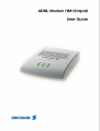
ADSL Modem HM121dp/di - User Guide
Copyright
This manual is published by Ericsson AB, without any warranty. Improvements and changes to this manual necessitated by
typographical errors, inaccuracies of current information, or improvements to programs and/or equipment, may be made by
Ericsson AB at any time and without notice. Such changes will, however, be incorporated into new editions of this manual.
All rights reserved.
© Ericsson AB 2003
© Ericsson AB 2003
All rights reserved
Contents
1
Introduction
5
1.1
About this Guide
5
1.2
1.3
About ADSL
About the ADSL Modem HM121dp/di
1.3.1 Protocol and Device Driver Selection
Package Contents
System Requirements
LED Indicators
5
6
6
7
8
8
1.4
1.5
1.6
2
Installation Procedure
2.1
2.2
2.3
2.4
3
Before You Start
Driver Installation
Connect the Modem
Installation Program Group
9
9
9
15
16
Accessing the Internet
17
3.1
17
18
18
18
19
19
20
21
3.2
4
Page
Using LAN Driver
3.1.1 In Windows 98, 98SE and ME
3.1.2 In Windows 2000
3.1.3 In Windows XP
Using WAN Driver
3.2.1 In Windows 98, 98SE and ME
3.2.2 In Windows 2000
3.2.3 In Windows XP
Verifying your ADSL Connection
22
4.1
4.2
Using the ADSL Modem icon
Using the Modem Control Panel
4.2.1 Physical Link
4.2.2 System Information
4.2.3 Configuration
22
22
22
23
24
5
Customizing Communication Settings
26
6
Uninstalling and Updating Modem Software
28
6.1
6.2
28
30
7
8
Software Uninstall
Updating Modem Software
Troubleshooting
32
7.1
7.2
7.3
32
32
32
The USB Cable Connected First
The Modem is not Detected by Your System
Checking Modem Status
Important Information
EN/LZT 108 6429 R1
May 2003
34
3 (47)
8.1
8.2
8.3
Product Care and Maintenance
Licence Agreement
8.2.1 Licence
8.2.2 Term
8.2.3 Limited Warranty
8.2.4 Intended Use
8.2.5 Limitation of Liability
8.2.6 Governing Law
Regulatory Information
8.3.1 Europe
8.3.2 USA
8.3.3 Caution
8.3.4 Environmental Information
8.3.5 Intended Use
Glossary
4 (47)
34
34
34
35
35
35
36
36
37
37
39
43
43
44
45
EN/LZT 108 6429 R1
May 2003
Introduction
1
Introduction
1.1
About this Guide
This User Guide provides general information about the installation of the Ericsson
ADSL Modem HM121dp/di in a PC/Windows environment, as well as information
about day-to-day use of the modem.
You can learn more about unfamiliar or technical terms by consulting the "Glossary"
in this guide.
The following chapters are included in this guide:
1.2
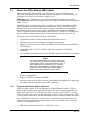
•
Chapter 1 - "Introduction" provides features of the HM121dp/di as well as a brief
description of ADSL and protocol and device driver selection.
•
Chapter 2 - "Installation Procedure" describes the steps for installing and
connecting the HM121dp/di in a PC/Windows environment.
•
Chapter 3 - "Accessing the Internet" provides instructions about how to access
the Internet when using either the LAN or WAN device driver.
•
Chapter 4 - "Verifying your ADSL Connection" describes how to use the ADSL
Modem icon and the Control Panel of the modem to configure and check the
performance of the HM121dp/di and the ADSL connection.
•
Chapter 5 - "Customizing Communication Settings" provides steps for altering
the ATM Virtual Path ID (VPI), ATM Virtual Circuit ID (VCI), Encapsulation
type and/or Modulation type values previously defined.
•
Chapter 6 - "Uninstalling and Updating Modem Software" describes the
procedure for uninstalling the modem software and also how to update to a new
version of the modem software.
•
Chapter 7 - "Troubleshooting" provides information about how to verify your
modem installation and also some tips and solutions for resolving some of the
problems that might encounter while installing or using your modem.
•
Chapter 8 - "Important Information" provides information about License
Agreement and Regulatory Information.
•
The "Glossary" includes abbreviations and explanations to technical terms used in
this guide.
About ADSL
The ADSL (Asymmetric Digital Subscriber Line) technology provides high-speed
data access across regular phone lines (copper wires) by making use of previously
unused frequency bandwidth above the voice band. By placing the ADSL signal
above the frequency of the voice signal, ADSL service is able to coexist on the same
line with your telephone service. ADSL is symmetric in the sense that it provides a
higher data rate in the downstream (receive) direction than in the upstream (transmit)
direction. Asymmetric operation is ideal for typical home and small office use where
files and information are downloaded more frequently than uploaded.
The HM121dp/di is capable of supporting the following DSL standards: ANSI T1.413
Issue 2, ITU G.992.1 (G.DMT), ITU G.992.2 (G.lite), and ITU G.992 Annexes A, B
and C as applicable.
EN/LZT 108 6429 R1
May 2003
5 (47)
Introduction
1.3
About the ADSL Modem HM121dp/di
The Ericsson ADSL Modem HM121d comes in two versions: HM121dp and
HM121di. Both products offer the same features, but they rely on different types of
telephone line in order to provide the ADSL service.
HM121dp offers ADSL service over POTS (Plain Old Telephone System) lines,
while HM121di uses ISDN (Integrated Services Digital Network) lines to provide the
ADSL service.
The HM121dp/di is easily connected to a USB port on the PC via a standard USB
cable (supplied). The modem uses power from the PC via the USB cable, which
eliminate the need of a power cable and AC adapter. An intuitive self-installation
wizard then guides the user step-by-step through the entire software installation
process. When new features and updates of the modem's software are available, they
may be added by simply loading a new version of the device driver onto the PC.
The main features of the HM121dp/di are listed below:
•
•
•
Compliant with Universal Serial Bus Specification Revision 1.1.
USB bus-powered; an external power supply is not required.
Supports two device drivers: Microsoft NDIS 4.0 WAN Miniport and NDIS 4.0
LAN Miniport.
•
Compatible with T1.413 i2, G.DMT, and G.lite compliant CO DSLAM
equipment.
•
Up to 8 Mbps downstream and at least 640 Kbps upstream for full-rate operation.
Note:
The actual rate depends on the copper category of
your telephone wire, distance from the central office
and the type of ADSL service subscribed to. Also, if
other USB devices are attached to your computer
sharing the fixed bandwidth of USB controller, the
performance of the USB modem will be slightly
influenced and thus effects the actual speed.
•
•
•
1.3.1
Protocol and Device Driver Selection
ADSL modems employ ATM (Asynchronous Transfer Mode) framing. ATM is a
protocol that divides packets into small fixed sized cells for rapid transmission over
high-speed networks. The ATM protocol allows various types of traffic (e.g. data,
voice, and video) to be securely and efficiently carried over the same network. ATM
is being widely deployed by telecommunications carriers in their backbone networks.
Several different protocols are used on top of ATM. The protocol required in your
configuration depends on the equipment deployed by your ADSL service provider.
There are several possibilities:
•
6 (47)
Software upgradeable.
Support for PPP over Ethernet (PPPoE).
Includes a Microsoft Windows control panel monitoring program for configuring
the adapter and checking the status of the connection.
PPP (Point to Point Protocol) over ATM (RFC 2364)
EN/LZT 108 6429 R1
May 2003
Introduction
PPP provides session setup, user authentication (login), and encapsulation for
upper layer protocols such as IP (Internet Protocol). The use of PPP makes the
modem appear as a dial-up modem to the operating system and Dial-Up
Networking is used to establish a connection.
•
Bridged Ethernet over ATM (RFC 1483B) / Routed IP over ATM (RFC 1483R).
This protocol makes the modem appear as a LAN (Local Area Network) device to
the operating system.
•
Classical IP over ATM (RFC 1577)
This is another LAN alike protocol for IP address and ATM address mapping.
•
PPP (Point to Point Protocol) over Ethernet (RFC 2516)
This protocol, commonly called PPPoE, allows multiple computer users on an
Ethernet to share a common ADSL connection to the Internet.
For the HM121dp/di there are two types of device drivers available: WAN and LAN
which both support the ATM protocol.
1.4
•
WAN driver
This driver causes the modem to resemble a dial-up modem. Call establishment is
performed through Dial-Up Networking. This driver supports PPP over ATM
(RFC 2364) with PVC connections. PPP over Ethernet (RFC 2516) is embedded
into this driver.
•
LAN driver
This driver makes the modem appear as a LAN or Ethernet device. The
connection establishment is automatic. This driver supports Bridged Ethernet over
ATM (RFC 1483B) and Routed IP over ATM (RFC 1483R) with PVC
connections. Classical IP over ATM (RFC 1577) is also supported by this driver.
PPPoE is supported via third party software when implemented with a LAN
driver. After installing the LAN driver, follow the installation instructions
provided with the third party PPPoE software. The third party software will search
for existing drivers and Internet connection will be made through the third party
software. You will be required to enter your User name and Password.
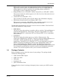
Package Contents
Before installation, please check the items of your package. The package should
include the following items:
•
•
•
•
•
ADSL Modem HM121dp/di
ADSL Line cable
USB cable
Installation CD
Quick Installation Guide
If any of the above items is missing or damaged, please contact your ADSL modem
provider.
EN/LZT 108 6429 R1
May 2003
7 (47)
Introduction
Note:
Your package may also include other materials
provided by your ADSL operator.
1.5
System Requirements
In order to successfully connect and install the HM121dp/di to your PC, please check
the following requirements with your equipment:
1.6
•
•
•
Pentium II 233 MHz or above
At least 32 MB RAM (64 MB recommended)
Microsoft Windows 98/98SE/Me/2000/XP. For Windows 98/98SE the Windows
Installation CD may be required.
•
•
•
20 MB of free hard disk space.
CD-ROM drive.
One available USB port.
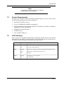
LED Indicators
There are three LED (Light Emitting Diodes) indicators located on top of the modem
which indicate the ADSL connection status. These LEDs indicate the current state of
the modem, and a description is provided in the table below:
LED
Status
Description
USB
On
Power On
Off
Power off or Suspend mode
Flashing
ADSL line is "training" to achieve the optimum transmission rate.
Solid
ADSL link is established and ready for use.
Off
No signal.
Flashing
Transmitting or receiving data
Off
No data traffic
ADSL
DATA
8 (47)
EN/LZT 108 6429 R1
May 2003
Installation Procedure
2
Installation Procedure
The step-by-step instructions in this chapter guides you through the complete
installation procedure for all supported operating systems. Notes will indicate when
operating system specific differences occur.
The installation procedure is divided into two steps:
2.1
•
Driver installation;
Installation of driver and, if required, user parameter input.
•
Connect the modem;
The physical cable connections.
Before You Start
Prior to installing the driver, consult with your ISP or system administrator about the
connection type and collect related information. You will be prompted for these
information during installation.
Connection Type
Encapsulation and Multiplexing method
Network Information
LAN
RFC 1577 Classical IPoATM
TCP/IP information:
RFC 1483 IPoATM Bridged LLC Encapsulation
- IP address
RFC 1483 IPoATM Bridged VC Encapsulation
- Subnet mask
RFC 1483 IPoATM Routed LLC Encapsulation
- DNS
RFC 1483 IPoATM Routed VC Encapsulation
- Gateway
RFC 2364 PPPoATM LLC Encapsulation
Internet Account information:
RFC 2364 PPPoATM NULL Encapsulation
- User name
RFC 2516 PPPoE Encapsulation
- Password
WAN
In addition you need the following information:
•
•
2.2
Modulation (Transmission Standards): T1.413, Multimode, G.Lite or G.DMT
The values of VPI and VCI
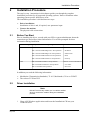
Driver Installation
Note:
DO NOT connect any cables yet. You will be notified
when to connect the modem during the installation
process.
1
Close ALL Windows applications and insert the Installatioin CD into your
CD-ROM drive.
EN/LZT 108 6429 R1
May 2003
9 (47)
Installation Procedure
From Windows Start menu, select Run and type D:\setup.exe (where D: is the
letter of your CD-ROM drive) and press Enter.
10 (47)
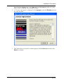
2
A "License Agreement" is displayed. Click Accept to proceed. Decline will exit
the setup program.
3
The "Select Service Provider" window appears. With Advanced selected, click
Next> to continue.
EN/LZT 108 6429 R1
May 2003
Installation Procedure
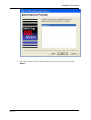
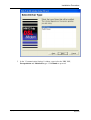
4
The "Select Driver Type" window appears. Select the driver type and click
Next>.
EN/LZT 108 6429 R1
May 2003
11 (47)
Installation Procedure
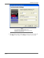
5
12 (47)
In the "Communication Settings" window, enter/select the VPI, VCI,
Encapsulation and Modulation type. Click Next> to proceed.
EN/LZT 108 6429 R1
May 2003
Installation Procedure
Note:
The Encapsulation types that appear in the
drop-down list vary depending upon the type of driver
selected in the previous step.
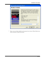
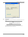
6
When the "Ready to Install" window appears, you may review your settings and
click <Back to make changes or click Next> to accept the current settings.
EN/LZT 108 6429 R1
May 2003
13 (47)
Installation Procedure
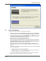
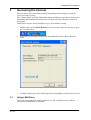
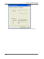
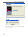
7
14 (47)
Drivers are now being installed, and a progress bar is shown. When finished, you
will be notified to connect the modem:
EN/LZT 108 6429 R1
May 2003
Installation Procedure
2.3
Connect the Modem
Connect the modem according to the following instructions:
1
2
Connect one end of the provided ADSL Line cable to the modem's LINE port.
Connect the other end to the ADSL service port (splitter/filter or phone outlet).
Connect the square plug of the provided USB cable to the USB port on the back
of the modem. Connect the flat plug to the USB port on your PC. This port is
most likely marked with the standard USB symbol.
Important Notes on attaching other USB Devices:
If you are going to attach other USB devices, such as USB mouse, keyboard or
hub, please plug them to your PC before connecting the modem. Otherwise, the
pre-attached USB modem will consume a fixed bandwidth and the remaining
bandwidth will not be enough for other USB devices.
If this is the case, you will se an error message warning you that the USB
controller bandwidth is exceeded. The additional USB device may not function
properly.
For example, your modem is attached already and you need to add an USB mouse
to your PC. In this case:
•
•
3
Unplug the modem to release the bandwidth.
Plug the USB mouse to your PC and then re-plug the modem. The modem
will now adjust to use the remaining bandwidth.
As soon as the USB cable is connected to the PC, the "Found New Hardware"
dialog is shown and the installation of the drivers proceeds.
EN/LZT 108 6429 R1
May 2003
15 (47)
Installation Procedure
Note:
Windows 98. At this point there may be a need for
you to insert the Windows Installation CD to install
some Microsoft network components. Insert the CD in
the disk drive, and click OK, if prompted.
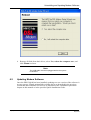
2.4
4
The system must be rebooted to have the new settings take effect, therefore the
"Reboot" window appears:
5
Remove all disks from their drives, select Yes, reboot the computer now, and
click Close to reboot.
Installation Program Group
The modem software installation procedure created a program group on your PC
which is reached from the Start menu by selecting Programs -> HM121dp/di DSL
Modem. This program group provides shortcusts to:
16 (47)
•
Configure - which opens the "Communication Settings" window from which you
can view and change configuration settings.
•
Uninstall - the Uninstallation program (described in the "Uninstalling and
Upgrading Modem Software" chapter).
EN/LZT 108 6429 R1
May 2003
Accessing the Internet
3
Accessing the Internet
The way how to access the Internet differs depending on the settings your ADSL
service provider is using.
The "Control Panel" provides information about which driver type that is used in your
installation and from that information you can proceed to the respective sections in
this chapter.
Follow these steps to check which driver type your modem is using:
3.1
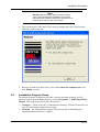
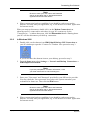
1
Double-click on the ADSL Modem icon (two arrows) in the system tray to open
the "Control Panel":
2
Select the "System Info" tab and read the information in the "Driver Release"
field:
3
Continue reading one of the following sections depending on which driver is used.
Using LAN Driver
The LAN driver makes the modem appear as a LAN or Ethernet device and the
connection establishment is automatic.
EN/LZT 108 6429 R1
May 2003
17 (47)
Accessing the Internet
If you have not been provided any IP settings from your ISP/service provider, you can
directly access the Internet by using a web browser.
If your ISP/service provider has provided you with IP settings (for instance IP address,
subnet mask and default gateway), and/or explicitly stated that DHCP is not used, you
have to change your PCs network configuration before you can access the Internet.
Follow the steps below to change your PCs network configuration:
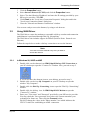
3.1.1
In Windows 98, 98SE and ME
1
2
3
4
5
6
From the Start menu select Settings -> Control Panel and double-click on the
Network icon.
Select the "TCP/IP protocol" together with "HM121dp/di DSL Modem" and click
the Properties button.
Select the IP Address tab.
Select "Specify an IP address" and enter the IP settings provided by your
ISP/service provider. Click OK.
Click OK in the "Network" dialog box and close the Control Panel.
Some configuration files may be copied to your hard disk and if a "Settings
Changes" message asks you to restart your PC, you should answer Yes.
You are now ready to access the Internet, by using a web browser.
3.1.2
In Windows 2000
1
2
3
4
5
6
7
From the Start menu select Settings -> Control Panel and double-click on the
Network and Dial-up Connections.
Double-click on the Local Area Connection icon for the "HM121dp/di DSL
Modem". Be sure to choose the correct one, if you have several dial up icons.
Click the Properties button.
Select Internet Protocol (TCP/IP) and click the Properties button.
Select "Specify an IP address" and enter the IP settings provided by your
ISP/service provider. Click OK.
Click OK in the "Local Area Connection Properties" dialog box and click Close
in the "Local Area Connection Status" dialog box.
Close the "Network and Dial-up Connections" window.
You are now ready to access the Internet, by using a web browser.
3.1.3
In Windows XP
1
2
18 (47)
From the Start menu select Control Panel and
double-click on the Network Connections (Classic View)
or
double-click on the links Network and Internet Connections followed by
Network connections (Category View).
Double-click on the Local Area Connection icon for the "HM121dp/di DSL
Modem". Be sure to choose the correct one, if you have several dial up icons.
EN/LZT 108 6429 R1
May 2003
Accessing the Internet
3
4
5
6
7
Click the Properties button.
Select Internet Protocol (TCP/IP) and click the Properties button.
Select "Use the following IP address" and enter the IP settings provided by your
ISP/service provider. Click OK.
Click Close in the "Local Area Connection Properties" dialog box and in the
"Local Area Connection Status" dialog box.
Close the "Network and Internet Connections" window.
You are now ready to access the Internet, by using a web browser.
3.2
Using WAN Driver
The WAN driver causes the modem to reassemble a dial-up modem and connection
establishment is performed through Dial-Up Networking.
The WAN driver also includes support for PPPoE (Point-to-Point Protocol over
Ethernet).
Follow the steps below to make a dial-up connection to access the Internet.
Note:
You have to use this method every time you want to
access the Internet.
3.2.1
In Windows 98, 98SE and ME
1
2
3
4
5
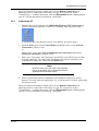
Double-click on the shortcut icon HM121dp/di Dial-up PPP Connection on
your PCs desktop to open the "Connect To" window. Now, proceed to step 5.
If you do not have the shortcut icon on your desktop, proceed to step 2.
Double-click on the icon My Computer on your PCs desktop to open the
window "My Computer".
Double-click the Dial-Up Networking icon to open the "Dial-Up Networking"
window.
Double-click the dial-up icon for HM121dp/di DSL Modem to open the
"Connect To" window.
Enter your "User name" and "Password" provided by your ISP/service provider.
You may check the "Save password" box to have the system remember your
credentials for future use. Then click the Connect button.
DO NOT change the values in the "Phone number" box which indicates the
VPI/VCI values for establishing an ADSL connection
EN/LZT 108 6429 R1
May 2003
19 (47)
Accessing the Internet
Note:
Be sure to enter your User name and Password
exactly as provided, that is, distinguish between
uppercase and lowercase letters.
6
When a connection has been established, you should be ready to access the
Internet. You may start your application, e.g. a web browser or E-mail application
for Internet access.
When you want to disconnect, double-click on the Modem Connection icon
(showing two PCs connected to each other) in your PCs system tray. In the
"Connected to ..." window that opens, click the Disconnect button. Shutting down
your PC will also disconnect your dial-up connection.
3.2.2
In Windows 2000
1
Double-click on the shortcut icon HM121dp/di Dial-up PPP Connection on
your PCs desktop to open the "Connect To" window. Now proceed to step 3.
2
If you do not have the shortcut icon on your desktop, proceed to step 2.
From the Start menu select Settings -> Network and Dial-up Connections ->
HM121dp/di DSL Modem.
Note:
If you are prompted for "Location Information", enter
your area code and then exit the dialog box.
3
Enter your "User name" and "Password" provided by your ISP/service provider.
You may check the "Save password" box to have the system remember your
credentials for future use. Then click the Dial button.
Note:
Be sure to enter your User name and Password
exactly as provided, that is, distinguish between
uppercase and lowercase letters.
4
20 (47)
When a connection has been established, you should be ready to access the
Internet. You may start your application, e.g. a web browser or E-mail application
for Internet access.
EN/LZT 108 6429 R1
May 2003
Accessing the Internet
When you want to disconnect, double-click on the Modem Connection icon
(showing two PCs connected to each other) in your PCs system tray. In the
"Connected to ..." window that opens, click the Disconnect button. Shutting down
your PC will also disconnect your dial-up connection.
3.2.3
In Windows XP
1
2
3
Double-click on the shortcut icon HM121dp/di Dial-up PPP Connection on
your PCs desktop to open the "Connect To" window. Now proceed to step 3.
If you do not have the shortcut icon on your desktop, proceed to step 2.
From the Start menu select Control Panel and double-click on the Network
Connections (Classic View)
or
double-click on the links Network and Internet Connections followed by
Network Connections (Category View).
Enter your "User name" and "Password" provided by your ISP/service provider.
You may check the "Save password" box to have the system remember your
credentials for future use. Then click the Dial button.
Note:
Be sure to enter your User name and Password
exactly as provided, that is, distinguish between
uppercase and lowercase letters.
4
When a connection has been established, you should be ready to access the
Internet. You may start your application, e.g. a web browser or E-mail application
for Internet access.
When you want to disconnect, double-click on the Modem Connection icon
(showing two PCs connected to each other) in your PCs system tray. In the
"Connected to ..." window that opens, click the Disconnect button. Shutting down
your PC will also disconnect your dial-up connection.
EN/LZT 108 6429 R1
May 2003
21 (47)
Verifying your ADSL Connection
4
Verifying your ADSL Connection
When the installation procedure has been completed, you can use the Control Panel to
view the current modem status regarding performance and ADSL connection.
4.1
Using the ADSL Modem icon
During driver installation, an ADSL Modem monitoring program is also installed on
your system. Whenever you start Windows, the utility is launched automatically with
its icon loaded in your system tray to indicate whether the physical connection
between your USB modem and the ISP is up or down:
If the ADSL Modem icon does not appear in your system tray, you can manually start
the utility by double-clicking the ADSL Modem HM121dp/di icon in the Control
Panel. This opens the Modem Control Panel and launches the utility icon at the same
time.
The ADSL Modem icon consists of two arrows. The upward arrow indicates data is
being transmitted whereas the downward arrow indicates data is being received. The
arrows are flashing yellow alternatively to indicate that trianing is in progress.
To identify the connection status, you can also move the cursor over the icon to see
the pop-up text as the following examples:
The physical link over the ADSL line is essential before you make a connection to
your ISP or corporate networks. If your ADSL connection fails, contact your ISP or
system administrator for troubleshooting.
4.2
Using the Modem Control Panel
When your ADSL session is active, you can view specific information on your ADSL
link. Double-click on the ADSL Modem icon (two arrows) in the system tray to open
the Control Panel.
The Modem Control Panel consists of three tabs as described in the following
sections.
4.2.1
22 (47)
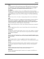
Physical Link
The "Physical Link" tab of the Control Panel views the current state of the modem and
the ADSL connection, as shown in the example below. When this window is open, the
information is updated every 2 seconds.
EN/LZT 108 6429 R1
May 2003
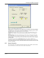
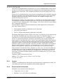
Verifying your ADSL Connection
Figure 17: Control Panel - Physical Link tab
State indicates TRAINING when the ADSL line is "training" to achive the optimum
transmission rate. Once the line is trained the indication is changed to DATA. When
no ADSL signal is present the indication is NO SIGNAL.
Modulation shows the ADSL mode used. The setting is determined by the service
offered by your ADSL service provider and is normally either T1.413, G.Dmt or
G.Lite.
Data Rate(kbps) shows the transmission rate. The value for "Transmit" shows the
speed (kbps) from your computer to the ISP/service provider (uploading), while the
value for "Receive" shows the speed from the ISP/service provider to your computer
(downloading).
The indicator (circle) below Link Status blinks green when the ADSL line is
"training" to achieve the optimum transmission rate, and turns solid green when the
line is trained and ready for use. Individual flashing yellow indicators show the "Data
Activity" separately.
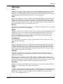
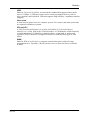
4.2.2
System Information
The "System Info" tab includes information about the release number of the modem
driver and firmware as well as the version of the Control Panel.
EN/LZT 108 6429 R1
May 2003
23 (47)
Verifying your ADSL Connection
Figure 18: Control Panel - System Info tab
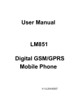
4.2.3
Configuration
The "Configuration" tab of the Control Panel views communication settings for your
modem.
Note:
The information displayed on the "Configuration" tab
differs depending on which driver type that is used in
your installation.
When using the LAN driver, you are able to view the Encapsulation type and
VPI/VCI values as shown in the example below:
24 (47)
EN/LZT 108 6429 R1
May 2003
Verifying your ADSL Connection
If you are using the WAN driver, only the Modulation type will be displayed.
EN/LZT 108 6429 R1
May 2003
25 (47)
Customizing Communication Settings
5
Customizing Communication Settings
Once the ADSL Modem HM121dp/di and software have been installed, the
communication settings may be easily updated by performing the following steps.
Note:
The communication settings should only be changed if
you have received new information from your ADSl
service provider
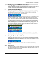
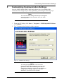
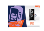
1
2
From your PC desktop click Start -> Programs -> HM121dp/di DSL Modem
-> Configure.
The "Communication Settings" window appears:
Figure 20: Communication Settings
Note:
The settings displayed in the "Communication
Settings" window differs depending on which driver
type that is used in the installation (in the above
example, the LAN driver is used). The possibilities to
change specific settings might also have been
disabled by your ADSL service provider.
26 (47)
EN/LZT 108 6429 R1
May 2003
Customizing Communication Settings
3
4
Make the necessary changes to the VPI, VCI, Encapsulation type and/or
Modulation Type and click the Next> button.
The system must be rebooted to have the new settings take effect, therefore the
"Reboot" window will appear. Remove all disks from their drives, select "Yes,
reboot the computer now" and click Close to reboot.
EN/LZT 108 6429 R1
May 2003
27 (47)
Uninstalling and Updating Modem Software
6
Uninstalling and Updating Modem Software
6.1
Software Uninstall
The HM121dp/di is a hot swapable USB device. You may plug it in and out without
powering down your computer. However, this does not mean that both driver and
software are removed when plugging out the USB device. Should you need to remove
the HM121dp/di driver and software, follow the steps below:
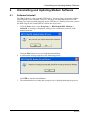
1
28 (47)
Click the Start menu, select Programs -> HM121dp/di DSL Modem ->
Uninstall. A message is displayed, asking you to confirm the removal of the
modem software:
2
Click the Yes button to proceed with the uninstallation.
A notification message appears as the following picture:
3
Click OK to start the uninstallation.
The uninstallation now starts and a progress bar is displayed during the process:
EN/LZT 108 6429 R1
May 2003
Uninstalling and Updating Modem Software
4
When the below notification message appears, unplug the modem from your PC
and click OK.
5
The system must be rebooted to have the new settings take effect, therefore the
"Reboot" window appears:
EN/LZT 108 6429 R1
May 2003
29 (47)
Uninstalling and Updating Modem Software
6
Remove all disks from their drives, select Yes, reboot the computer now, and
click Close to reboot.
Note:
The USB cable must be unplugged before the system
is rebooted.
6.2
Updating Modem Software
Once the HM121dp/di has been installed, updating to a new version of the software is
an easy process. Simply uninstall the existing drivers as described in the previous
section and then install the new drivers as described in the "Installation procedure"
chapter in this manual or in the provided Quick Installation Guide.
30 (47)
EN/LZT 108 6429 R1
May 2003
Uninstalling and Updating Modem Software
Note:
Before you uninstall the driver, view the current
configuration via Start -> Programs -> HM121dp/di
DSL Modem -> Configure. Write down your modem
settings, e.g. VPI/VCI values, encapsulation, etc. You
will need to provide these information when installing
the new driver.
EN/LZT 108 6429 R1
May 2003
31 (47)
Troubleshooting
7
Troubleshooting
This chapter provides some tips and solutions for resolving some of the problems that
might encounter while installing or using your modem.
7.1
The USB Cable Connected First
If the USB cable is connected between the modem and the PC before the Installation
CD is inserted, the "Add/Found New Hardware Wizard" will start indicating that new
drivers are required. If this is the case, follow the steps below:
7.2
1
Disconnect the USB cable from the PC.
2
Click Cancel in the "Add/Found New Hardware Wizard" window to exit the
wizard.
3
Remove and insert the Installation CD again to start the modem installation
procedure.
The Modem is not Detected by Your System
If the installation procedure fails due to that the modem cannot be detected by your
system, try the following:
Cause
Solution
The modem is not connected properly to the USB Check that the modem and the USB cable are
port, the USB port may be faulty or the modem is connected properly to the USB port.
not installed properly.
Disconnect the USB cable from the modem, wait
for some seconds before reconnecting it.
Restart the computer.
If possible, verify that the USB cable is not faulty
by connecting it to another USB device.
Remove the previous installation (uninstall),
disconnect the USB cable and reinstall the modem
according to instructions in the "Installation
Procedure" chapter or in the provided Quick
Installation Guide.
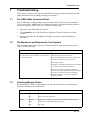
7.3
Checking Modem Status
By observing the LEDs on your modem you can check if the device is functioning
properly according to the table below:
LED
Status
Description
USB
On
Power On
Off
Power off or Suspend mode
Flashing
ADSL line is "training" to achieve the optimum transmission rate.
Solid
ADSL link is established and ready for use.
Off
No signal.
ADSL
32 (47)
EN/LZT 108 6429 R1
May 2003
Troubleshooting
LED
Status
Description
DATA
Flashing
Transmitting or receiving data
Off
No data traffic
The Control Panel can also be used to view the current state of the ADSL connection.
Follow the steps below to access the Control Panel:
1
Double-click on the ADSL Modem icon (two arrows) in your PC's system tray.
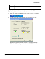
2
When the Control Panel windows appears, select the "Physical Link" tab:
State indicates TRAINING when the ADSL line is "training" to achieve the
optimum transmission rate. Once the lines is trained the indication is changed to
DATA. If no ADSL signal is present the indication is NO SIGNAL.
EN/LZT 108 6429 R1
May 2003
33 (47)
Important Information
8
Important Information
8.1
Product Care and Maintenance
Note:
This is guidelines for safe and efficient use. Read this
information before using your Ericsson ADSL Modem
HM121dp/di.
Your ADSL Modem HM121dp/di is a highly sophisticated electronic device. To get
the most out of your modem, be sure to read the following text about product care,
safety and efficient use.
Do not expose the product to liquid or moisture.
Do not expose the product to extreme temperatures, neither hot nor cold.
Do not expose the product to lit candles, cigarettes, cigars, open flames, etc.
Do not drop, throw or try to bend the product. Rough treatment may damage the
product.
Do not attempt to disassemble your product; the warranty is no longer valid if the
warranty seal has been broken. The product does not contain consumer serviceable
components. Service should only be performed by Certified Service Centres.
Do not allow children to play with the modem as it contains small parts that could be
detached and create a choking hazard.
Avoid using this telephone equipment during an electrical storm. There may be a
remote risk of electric shock from lightning.
Use only original Ericsson components and replacement parts. Failure to do so may
result in performance loss, damage to the product, fire, electric shock or injury, and
will invalidate the warranty.
Treat the product with care, keep it in an clean and dust free place. Use only a soft,
damp cloth to clean the product.
8.2
Licence Agreement
This is a legal agreement, Agreement, between you Licensee, the recipient of the
enclosed Software in modem, on compact disc, diskette or any other media and any
upgrades thereof, and Ericsson AB, the Vendor. By opening the sealed software
package and/or using the software you are agreeing to be bound by the terms of this
Agreement.
8.2.1
34 (47)
Licence
The Licensee is hereby granted a non-transferable, non-exclusive, restricted right and
license to use the software included herein, Software. However, the Software licensed
hereunder may be delivered in an inseparable package also containing other software
programs than the Software.
You may: (a) use the enclosed Software on a single Ericsson product; (b) make copies
of the Software solely for purposes of backup. The copyright notice must be
reproduced and included on a label on any backup copy.
EN/LZT 108 6429 R1
May 2003
Important Information
You may not: subject to when applicable, the EC Council Directive of May 14, 1991
on the legal protection of computer programs (91/250/EEG) ("Software Directive"
Article 6) distribute copies of this Software or its documentation to others; modify,
rent, lease or grant your rights to this Software to third parties (except in the event the
Ericsson product containing an item of Software is transferred to a third party and
provided the transferee agrees in writing to be bound by the terms of this License
Agreement; translate, reverse engineer, decompile, disassemble or otherwise alter the
Software or its documentation or disclose any information designated as confidential
or proprietary at the time of disclosure or, by nature, is confidential or proprietary.
You may not: furnish any software or support material into any country in violation of
national export control regulation.
8.2.2
Term
Your license remains effective from the date of receipt until terminated. You can
terminate it at any other time by destroying the Software together with all copies of
the Software in any form. Your license will also automatically terminate without
notice if you fail to comply with any term or condition of this Agreement. Upon any
termination you must destroy all copies of the Software in any form.
8.2.3
Limited Warranty
Vendor warrants the media, on which the Software is provided, to be free of defects in
materials and workmanship under normal use for ninety (90) days after the date of
receipt. The Vendor's and its suppliers' entire liability and your exclusive remedy
under this warranty (which is subject to you returning the Software to an certified
reseller with a copy of your receipt) will be, at Vendor's option, to replace the disc(s)/
diskette(s) or refund the purchase price for the Software and terminate this
Agreement.
Except for the above express limited warranties, Vendor and its suppliers make and
you receive no warranties or conditions either express, implied, statutory or otherwise
and Vendor and its suppliers specifically disclaim any implied warranties of
merchantability and fitness for a particular purpose. Vendor does not warrant that the
Software will be uninterrupted or error free. You assume the responsibility for the
selection of the program and hardware to achieve your intended results; and for the
installation, use and results obtained from the Software.
Some jurisdictions do now allow limitations on duration of an implied warranty, so
the above limitation may not apply to you.
8.2.4
Intended Use
The Software shall be used in accordance with the instructions and for its intended use
and purpose only. The software or part of it is not permitted to be used in form
example life support systems, nuclear facility applications, missile technology,
chemical or biologized industry or of flight navigation or communication of air,
ground support equipment or other similar business, if failure to perform on behalf of
the software in any way, could result in personal injury, death, damage to tangibles or
environmental damage.
EN/LZT 108 6429 R1
May 2003
35 (47)
Important Information
8.2.5
Limitation of Liability
If no event shall Vendor or its suppliers be liable for any indirect or consequential
losses or damages whatsoever including loss of data, loss of business, loss of profits,
business interruption or personal injury arising out of the use of or inability to use this
Software. Vendor and its suppliers entire liability under this Agreement shall be
limited to the amount actually paid by Licensee for the Software.
8.2.6
Governing Law
The validity, construction and performance of this Agreement shall be governed by
the laws of Sweden.
36 (47)
EN/LZT 108 6429 R1
May 2003
Important Information
8.3
Regulatory Information
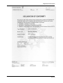
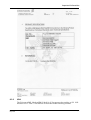
8.3.1
Europe
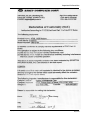
8.3.1.1 Declaration of Conformity
EN/LZT 108 6429 R1
May 2003
37 (47)
Important Information
38 (47)
EN/LZT 108 6429 R1
May 2003
Important Information
8.3.2
USA
The Ericsson ADSL Modem HM121dp/di is cULus approved according to UL 1950
and also to FCC Part 15 and Part 68 as described in the following sections.
EN/LZT 108 6429 R1
May 2003
39 (47)
Important Information
Note:
This information is only applicable for units sold for the
U.S. market.
8.3.2.1 UL Required Information
When using your telephone equipment, basic safety precautions should always be
followed to reduce the risk of fire, electric shock and injury to persons, including the
following:
1
2
3
Do not use this product near water, for example, near a bathtub, washbowl, and
kitchen sink or laundry tub, in a wet basement or near a swimming pool.
Avoid using a telephone (other than a cordless type) during an electrical storm.
There may be a remote risk of electric shock from lightning.
Do not use the telephone to report a gas leak in the vicinity of the leak.
CAUTION! To reduce the risk of fire, use only No. 26 AWG or larger
telecommunication line cord.
CAUTION! Always disconnect all telephone lines from the wall outlet before
servicing or disassembling this equipment. For use only with UL Listed Personal
Computer.
8.3.2.2 FCC Required Information
8.3.2.2.1 FCC Part 15
This device complies with Part 15 of the FCC Rules. Operation is subject to the
following two conditions: (1) This device may not cause harmful interference, and (2)
this device must accept any interference received, including interference that may
cause undesired operation.
This equipment has been tested and found to comply with the limits for a Class B
digital device, pursuant to part 15 of the FCC Rules (Code of Federal Regulations
Title 47, Telecommunications (CFR 47)). These limits are designed to provide
reasonable protection against harmful interference when the equipment is operated in
a residential installation.
This equipment generates, uses, and can radiate radio frequency energy and, if not
installed and used in accordance with these instructions, may cause harmful
interference to radio or television reception. However, there is no guarantee that
interference will occur in a particular installation. If this equipment does cause
harmful interference to radio or television, which can be determined by turning the
equipment off and on, the user is encouraged to eliminate the interference by one or
more of the following measures:
40 (47)
•
•
Reorient or relocate the receiving antenna of the affected equipment.
Increase the separation between the ADSL Modem HM121d and the affected
equipment.
•
Connect the ADSL Modem HM121d power supply to an outlet on a circuit
different from that to which the affected equipment is connected.
EN/LZT 108 6429 R1
May 2003
Important Information
•
Consult your service provider or an experienced radio/TV technician for help.
EN/LZT 108 6429 R1
May 2003
41 (47)
Important Information
42 (47)
EN/LZT 108 6429 R1
May 2003
Important Information
8.3.2.2.2 FCC Part 68
The Federal Communications Commission (FCC) has established Rules which permit
this device to be directly connected to the telephone network. Standardized jacks are
used for these connections. This equipment should not be used on party lines or coin
phones.
If this device is malfunctioning, it may also be causing harm to the telephone network;
this device should be disconnected until the source of the problem can be determined
and until repair has been made. If this is not done, the telephone company may
temporarily disconnect service.
The telephone company may make changes in its technical operations and procedures;
if such changes affect the compatibility or use of this device, the telephone company
is required to give adequate notice of the changes. You will be advised of your right to
file a complaint with the FCC.
If the telephone company requests information on what equipment is connected to
their lines, inform them of:
•
•
•
The telephone number to which this unit is connected.
The USOC jack required.
The FCC Registration Number (indicated on the label).
The Ringer Equivalence Number (REN). Note that if several devices are connected on
the same line, the RENs must not add up to more than 5.0. This REN figure is
important to your telco and can be found on the equipment's FCC compliance label.
In case of operational problems, disconnect your unit by removing the modular or
multi-connector plug from the telco's jack. If your regular phone still works properly,
your modem has a problem and must remain disconnected and (officially) serviced or
returned for repairs. If upon the above disconnection your regular phone still has
problems, notify your telco that they may have a problem. If problem is still found in
premises wiring not telco-installed, you are subject to a service charge. If a fault is
found in telco-installed wiring, you may still be subject to a service call charge.
Unless otherwise noted in the User's Manual (e.g. fuses, etc), user may not under any
circumstances (in our out of warranty) attempt any service adjustment, or repairs on
this unit. It must be returned to the factory or authorized U.S. service agency for all
such work. Locations and phone number orf factory or authorized U.S. service points
are as following:
Company: ASKEY International Corp.
Address: 1751 Yeager Ave, La Verne, CA 91750, USA
Tel: 909-596-5180
8.3.3
Caution
Changes or modifications to this product not autorized by te manufacturer could void
your authority to operate the equipment and invalidate approvals.
8.3.4
Environmental Information
Maximum environmental values during use:
•
•
Temperature: 0oC to +40oC
Humidity: 5% to 85% RH, non-condensing.
EN/LZT 108 6429 R1
May 2003
43 (47)
Important Information
8.3.5
44 (47)
Intended Use
The HM121dp/di is intended for indoor public and private use.
EN/LZT 108 6429 R1
May 2003
Glossary
Glossary
ADSL
Short for Asymmetric Digital Subscriber Line, a technology that allows more data to
be sent over existing copper telephone lines (POTS). ADSL support data rates of
fromm 1.5 to 9 Mbps when receiving data (known as the downstream rate) and from
16 to 640 Kbps when sending data (known as the upstream rate).
ATM
Short for Asynchronous Transfer Mode, a network technology based on transferring
data in cells or packets of a fixed size. The cell used with ATM is relatively small
compared to units used with older technologies. The small, constant cell size allows
ATM equipment to transmit video, audio, and computer data over the same network,
and assure that no single type of data hogs the line.
Device
Any machine or component that attaches to a computer. Examples of devices include
disk drives, printers, mice, and modems.
DHCP
Short for Dynamic Host Configuration Protocol, a protocol for assigning dynamic IP
addresses to devices on a network. With dynamic addressing, a device can have a
different IP address every time it connects to the network. In some systems, the
device's IP address can even change while it is still connected. Many ISP's use
dynamic IP addressing for dial-up users.
Downstream
The direction of a downstream signal is from the ISP/service provider to the user's
computer (downloading).
DSL
Short for Digital Subscriber Line, which is a data communications technology that
transmits information over the existing copper telephone lines (POTS). DSL takes
existing voice cables that connect customer premises (CPE) to the phone company's
central office (CO) and turns them into a high-speed digital linke. There are many
types of DSL and ADSL is one of them.
DSLAM
Short for Digital Subscriber Line Access Multiplexer, a mechanism at a phone
company's central location that links many customer DSL connections to a single
high-speed ATM line.
When the phone company receives a DSL signal, an ADSL modem with a POTS
splitter detects voice calls and data. Voice calls are sent to the PSTN, and data re sent
to the DSLAM, where it passes through the ATM to the Internet, then baack through
the DSLAM and ADSL modem before returning to the customer's PC.
Firmware
Software (programs or data) that has been written onto read-only memory (ROM).
Firmware is a combination of software and hardware.
G.dmt
A kind of asymmetric DSL technology, based on DMT modulation, that offers up to 8
megabits per second downstream bandwidth, 1.544 Megabits per second upstream
bandwidth. "G.dmt" is actually a nickname for the standard officially known as
ITU-T Recommendation G.992.1.
EN/LZT 108 6429 R1
May 2003
45 (47)
Glossary
G.lite
A kind of asymmetric DSL technology, based on DMT modulation, that offers up to
1.5 megabits per second downstream bandwidth, 384 Kilobits per second upstream,
does not usually require a splitter and is easier to install than other types of DSL.
"G.lite" is a nickname for the standard officially known as G.992.2.
IP address
An identifier for a computer or device on a TCP/IP network. Networks using the
TCP/IP protocol route messages based on the IP address of the destination. The format
of an IP address is a 32-bit numeric address written as four numbers separated by
periods. Each number can be zero to 255. For example, 1.160.10.240 could be an IP
address.
ISP
Short for Internet Service Provider, a company that provides access to the Internet.
LAN
Short for Local Area Network, a computer network that spans a relatively small area.
Most LANs are confined to a single building or group of buildings and connect
workstations and personal computers. However, one LAN can be connected to other
LANs over any distance via telephone lines and radio waves. A system of LANs
connected in this way is called a wide-area network (WAN).
There are many different types of LANs, where Ethernet being the most common for
PCs.
LED
Short for Light Emitting Diode, a type of control lamp on devices that indicates the
status of a device.
Password
A secret series of characters that enables a user to access a file, computer, or program.
On multiuser systems, each user must enter his or her password before the computer
will respond to commands.
POTS
Short for Plain Old Telephone Service, which refers to the standard telephone service
that most homes use. The POTS network is also called the Public Switched Telephone
Network (PSTN).
PPP
Short for Point-to-Point Protocol, a method of connecting a computer to the
Internet. PPP sends the computer's TCP/IP packets to a server that puts them onto the
Internet.
T1.413
The American National Standards Institute (ANSI) standard for asymmetric digital
subscriber line using discrete multitone modulation, which the G.dmt standard is
based on.)
TCP/IP
Short for Transmission Control Protocol / Internet Protocol, the suite of
communication protocols used to connect hosts on the Internet.
Upstream
The direction of an upstream signal is from the user's computer to the ISP/service
provider (uploading).
46 (47)
EN/LZT 108 6429 R1
May 2003
Glossary
USB
Short for Universal Serial Bus, an external bus standard that supports data transfer
rates of 12 Mbps. A USB port can be used to connect peripheral devices, such as
mice, modems, and keyboards. USB also supports Plug-and-Play installation and hot
plugging.
User name
A name used to gain access to a computer system. User names (and often passwords)
are required in multiuser systems.
VPI and VCI
A VPI (Virtual Path Identifier) is an 8-bit field while VCI (Virtual Channel
Identifier) is a 16-bit field in the ATM cell header. A VPI identifies a link formed by
a virtual path and a VCI identifies a channel within a virtual path. A unique and
separate VPI/VCI identifier is assigned in advance to indicate which type of cells
follow.
WAN
Short for Wide Area Network, a computer network that spans a relatively large
geographical area. Typically, a WAN consists of two or more local-area networks
(LANs).
EN/LZT 108 6429 R1
May 2003
47 (47)