1
HM220d ADSL Modem User Guide
HM220d ADSL Modem
User Guide
© Ericsson Mobile Communications AB 2000
All rights reserved
Copyright
This manual is published by Ericsson Mobile Communications AB, without any warranty. Improvements and changes to this manual
necessitated by typographical errors, inaccuracies of current information, or improvements to programs and/or equipment, may be
made by Ericsson Mobile Communications AB at any time and without notice. Such changes will, however, be incorporated into new
editions of this manual.
All rights reserved.
© Ericsson Mobile Communications AB
Trademark Identification Statements
ACROBAT is a registered trademark of Adobe Systems Incorporated .
ACROBAT READER is a registered trademark of Adobe Systems Incorporated.
MICROSOFT INTERNET EXPLORER is a trademark of Microsoft Corporation.
ERICSSON is a registered trademark of Telefonaktiebolaget L M Ericsson.
MICROSOFT, MICROSOFT WINDOWS and MICROSOFT WINDOWS NT are registered trademarks of Microsoft Corporation.
NETSCAPE is a registered trademarks of Netscape Communications Corporation.
WINDOWS CE, WINDOWS and WINDOWS NT are registered trademarks of Microsoft Corporation.
VIRATA is a registered trademark of Virata Corporation. All other trademarks, such as product and service names, are owned by
Virata or by third parties.
2 (87)
EN/LZT1083982 R4
2000-12-07
EN/LZT1083982 R4
2000-12-07
3 (87)
Innehåll
sida
1
Introduction
1.1
About this User Guide
1.1.1 Typographic conventions
1.2
About the HM220d ADSL modem
1.3
Package contents
1.4
Placement of the modem
1.4.1 Wall mounting instructions
1.5
Filter installation
2
Installation using Ethernet (for Windows 95 or higher PCs)
2.1
System requirements
2.2
Connecting equipment
2.3
Configuring the PC
10
10
11
12
3
Installation using USB (for Windows 98 PCs)
3.1
System requirements
3.2
Connecting equipment
3.3
Installing USB drivers
3.4
Configuring the PC
14
14
15
16
22
4
Installation using USB (for Windows 2000 PCs)
4.1
System requirements
4.2
Connecting equipment
4.3
Installing USB drivers
4.4
Configuring the PC
24
24
25
26
32
5
Configuring the modem
5.1
Accessing the modem's web pages
5.2
Auto configuration
5.3
Manual configuration
5.3.1 Routed/PPPoA mode
5.3.2 Routed/RFC1483 mode
5.3.3 Bridged/RFC1483 mode
5.4
Change configuration
5.5
Advanced settings
34
34
38
42
44
50
55
58
60
4 (87)
7
7
7
7
8
8
9
9
EN/LZT1083982 R4
2000-12-07
5.6
5.7
5.8
5.5.1 LAN
5.5.2 Routed
5.5.3 DHCP
5.5.4 Bridged
5.5.5 Customized
5.5.6 Management
Product Information
Status
Update the software
60
61
62
63
63
63
64
65
65
6
Operation
6.1
Modem LED indicator description
6.2
PipeLock
6.3
Operational states
6.3.1 Power-up diagnostics
6.3.2 Initialization
6.3.3 Operational
6.3.4 PipeLock mode
6.3.5 Access restricted
6.3.6 Power cycle
66
66
67
68
68
68
69
69
69
69
7
Technical reference
7.1
Factory default configuration
7.2
Specification of the HM220d ADSL modem
70
70
71
8
Trouble shooting
8.1
Configuring your PC when not using DHCP
8.2
Reset the modem to factory default configuration
72
72
74
9
Important information
9.1
Product care and maintenance
9.2
Licence agreement
9.2.1 Licence
9.2.2 Term
9.2.3 Limited warranty
9.2.4 Intended use
9.2.5 Limitation of liability
9.2.6 Governing law
9.3
Regulatory information
9.3.1 Safety Standards
9.3.2 Power Supply
75
75
75
76
76
76
77
77
77
77
77
77
EN/LZT1083982 R4
2000-12-07
5 (87)
9.3.3
9.3.4
Glossary
6 (87)
CE Requirement
USA
77
77
80
EN/LZT1083982 R4
2000-12-07
Introduction
1
Introduction
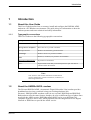
1.1
About this User Guide
This User Guide describes how to connect, install and configure the HM220d ADSL
modem in a PC/Windows environment. The guide also gives information on how the
modem operates and some technical and safety information.
1.1.1
Typographic conventions
This User Guide uses the following typographic conventions:
Example
Convention
View
Menus are printed in boldface.
Message Source Templates
Menu choices are printed in boldface
"Message Browser"
Windows are denoted by quotation marks.
GUI Design
Window choices are printed in boldface.
Next
Buttons (in windows) are printed in Arial boldface.
Subscription Administration
Hyperlinks are underlined.
<host>
Angle brackets mean that you should replace this part with what is
indicated within the brackets.
Note:
Text written in this manner indicates that what follows
presents clarification, specific instructions, comments, or
interesting information.
1.2
About the HM220d ADSL modem
The Ericsson HM220d ADSL (Asymmetric Digital Subscriber Line) modem provides
broadband services into your home using your existing telephone line.
Ericsson's HM220d ADSL modems comes in two versions: HM220dp and HM220di.
Both products offer the same features, but they do relay on different types of phone lines
to provide the ADSL service. HM220dp offers ADSL service over the Plain Old
Telephone System or POTS lines, while HM220di uses the Integrated Services Digital
Network or ISDN lines to provide the ADSL service.
EN/LZT1083982 R4
2000-12-07
7 (87)
Introduction
The overwhelming majority of telephone connections in the world are based on POTS. If
you have a "normal" or analog telephone in your home, HM220dp is the right modem for
you. On the other hand, if you have an ISDN or digital phone, you will need HM220di. If
you are not sure which version is the right one for you, please contact your service
provider.
The modem sends and receives very high-speed signals via the regular telephone
network, using Discrete Multi-tone (DMT) Digital Subscriber Line (DSL) transmission.
HM220d utilizes the expanded capacity of ADSL-ready telephone lines to handle
Internet and multimedia data, while allowing you to make and receive phone calls on the
same line.
When installing the HM220d ADSL modem, you have the option of connecting it to your
computer with either a USB connection (if supported by your computer) or an Ethernet
connection. The plug-and-play aspect of USB simplifies installation, requiring only a
cable plug-in and the installation of a driver (supplied on the CD-ROM). An Ethernet
connection, which requires that a Network Interface Card (NIC) be installed on your
computer, allows you to connect multiple computers to a single modem.
Once you are connected, a simple press of the PipeLock button (located on top of the
modem) guarantees the security of your computer. When PipeLock is activated, the
modem remains logged on to the network, but direct communication between your
computer and the outside world is blocked. This prevents outsiders from gaining access to
any information on your computer, even when you are not there. To resume Internet
access, simply press the PipeLock button again.
Time and technological development never stand still. Ericsson will keep you updated
with the latest technology, and let you download the latest software update.
1.3
Package contents
Your package should contain all the components listed below. If anything is missing or
damaged, please contact the dealer/service provider from whom the equipment was
purchased.
•
•
•
•
•
•
•
1.4
The HM220d ADSL modem
A power supply adapter with connecting cable
Telephone/ADSL cable
Ethernet cable
USB cable
Quick Guide
CD-ROM containing the printable User Guide and other utilities.
Placement of the modem
The HM220d ADSL modem can be mounted to the wall, or simply placed on a flat
surface.
8 (87)
EN/LZT1083982 R4
2000-12-07
Introduction
Pick a location for the HM220d ADSL modem that:
1.4.1
•
•
•
enables you to view the LEDs on top of the modem
allows you to reach and press the PipeLock button on top of the modem
is close to a power outlet, phone jack, and the computer (PC) to facilitate connections
to these devices
•
•
does not restrict air flow around the modem
allows plenty of room for cables to be routed from the back of the modem without
crimping the cables
Wall mounting instructions
The modem is mounted to the wall using two screws and the two mounting slots on the
bottom of the unit.
Follow the step-by-step instructions below to mount the modem to the wall:
1
2
1.5
Insert and secure screws to the wall at a distance of 100 mm (3,9"). If needed, drill
holes and insert plastic anchors or toggles first.
The screws should not be secured flush to the wall. Leave a gap of approximately
1/4" from the wall surface to the bottom of the screw head.
Slip the HM220d ADSL modem slots over the screw heads and pull down until the
unit is seated securely. A slight adjustment to the screws may be necessary to provide
a snug fit to the wall.
Filter installation
To maintain normal phone service, a special filter may need to be installed at your home.
This filter, sometimes called a splitter, splits the voice (phone) signal from the ADSL
(data) signal.
Set-up and installation charges for ADSL service typically include the filter installation.
If you are not sure if a filter needs to be installed, contact your service provider.
EN/LZT1083982 R4
2000-12-07
9 (87)
Installation using Ethernet (for Windows 95 or higher PCs)
2
Installation using Ethernet (for Windows 95 or
higher PCs)
This chapter describes the installation and configuration process using the Ethernet
interface in Windows 95 (or higher) PCs.
The Ethernet interface is used for those computers which do not have a USB interface, or
for networking multiple computers on the same broadband line.
This requires a Network Interface Card (NIC). The NIC must be installed in the computer
and the computer must be configured for TCP/IP. When this option is used, a standard
Ethernet cable carries data between the modem and the computer. An Ethernet interface,
used in conjunction with a hub, allows you to link up multiple computers to a single
HM220d ADSL modem.
2.1
System requirements
To successfully connect and install the HM220d ADSL modem to the Ethernet
connection you will need the following:
•
•
•
•
•
•
An ADSL-ready telephone line
133 MHz Processor and 16 MB RAM.
10Base-T Network Interface Card
CD-ROM drive
Windows® 95 or higher.
Internet browser - Internet Explorer 4.06 (or higher) or Netscape Navigator 4.5 (or
higher).
From the package you will need the following:
•
•
•
•
10 (87)
The modem
Telephone/ADSL cable
Ethernet cable
The power supply adapter with connecting cable.
EN/LZT1083982 R4
2000-12-07
Installation using Ethernet (for Windows 95 or higher PCs)
2.2
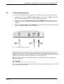
Connecting equipment
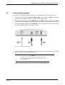
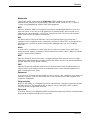
To connect your HM220d ADSL modem via the Ethernet interface, follow these steps:
1
2
3
Connect one end of the Telephone/ADSL cable to the modem's ADSL port and the
other end to the ADSL service port (wall jack or splitter/filter).
Connect one end of the Ethernet cable to the ETHERNET port on the back of the
modem and connect the other end to the Ethernet 10Base-T network card on your
computer.
Connect the Power cable to the POWER connector on the back of the modem. Plug
the power supply adapter into a power source.
Figur 1: Connect via Ethernet interface
Assuming the modem has been connected properly, the modem will enter the power-up
diagnostics state and verify the integrity of the hardware and software. Please refer to
chapter 6.3 Operational states, for further information. When this happens all of the LEDs
(light-emitting diodes) on top of the modem will turn ON briefly.
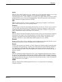
When the Power, Ethernet and ADSL LEDs have turned solid yellow, the modem is
ready for operation.
Figur 2: LED symbols for Power, Ethernet and ADSL
If not, check that the cables have been securely connected to both the modem, PC, ADSL
service port and power source.
EN/LZT1083982 R4
2000-12-07
11 (87)
Installation using Ethernet (for Windows 95 or higher PCs)
2.3
Configuring the PC
To be able to access the modem's built in web pages, the IP address for the PC must be
on the same IP net as the modem. A recommended way is to configure the PC as a DHCP
client and use the DHCP server in the modem to get a correct IP address.
If you are unsure how your PC is configured you can use the following instructions to
check, and maybe change, your settings.
Check TCP/IP settings:
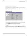
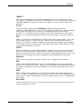
1
From the Start menu select Settings then Control Panel.
2
Double click on the Network icon and the "Network" dialog box appears:
Figur 3: Network dialog box
3
Select the TCP/IP protocol (together with the name of the type of physical network
adapter installed in your PC). See the above example.
4
5
Click the Properties button and the "TCP/IP Properties" dialog box will appear.
Select the IP Address tab and verify that "Obtain an IP address automatically" is
selected. If not, then select this button and click OK.
You are now back in the "Network" dialog box. Click OK.
Close the Control Panel window.
If you made any changes, some configuration files will be copied on your hard disk
and if a "Settings Changes" message asks if you wish to restart your computer you
should answer Yes.
6
7
8
12 (87)
EN/LZT1083982 R4
2000-12-07
Installation using Ethernet (for Windows 95 or higher PCs)
By following the next steps you can verify that your PC now has got a new IP address
from the modem's DHCP server.
Check IP configuration:
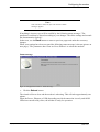
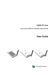
1
From the Start menu select Run... .
2
Type winipcfg and click OK. The "IP Configuration" dialog box appears:
Figur 4: IP Configuration dialog box
3
4
5
From the scroll down menu at the top, select the Ethernet adapter according to the
above example.
Verify that the "IP Address" is within the range 192.168.254.1 to 192.168.254.253.
If the "IP Address" field is empty or not within the specified range, click the
Release All button and then the Renew All button. Verify the "IP Address" again
according to step 4.
6
Click OK to close the "IP Configuration" dialog box.
Now, you are ready to configure your modem as described in chapter 5 - Configuring the
modem.
EN/LZT1083982 R4
2000-12-07
13 (87)
Installation using USB (for Windows 98 PCs)
3
Installation using USB (for Windows 98 PCs)
This chapter describes the installation and configuration process using the USB interface
in Windows 98 PCs.
Many computers today are shipped with a Universal Serial Bus (USB) port. With a USB
port, a Network Interface Card is not required, but a specific USB driver must be installed
on the computer. The USB drivers required for the HM220d ADSL modem is provided
on the CD-ROM, and is installed during the installation phase. This driver facilitates
communication between the modem and the computer. Unlike an Ethernet connection, a
USB connection does not allow for more than one computer to be linked to the modem.
3.1
System requirements
To successfully connect and install the HM220d ADSL modem to the USB interface you
will need the following:
•
•
•
•
•
An ADSL-ready telephone line
133 MHz Processor and 16 MB RAM.
USB port
CD-ROM drive
Windows® 98 (Windows installation CD might be required when installing the USB
driver).
•
Internet browser - Internet Explorer 4.06 (or higher) or Netscape Navigator 4.5 (or
higher).
From the package you will need the following:
•
•
•
•
•
14 (87)
The modem
Telephone/ADSL cable
USB cable
The power supply with connecting cable
The CD-ROM disk.
EN/LZT1083982 R4
2000-12-07
Installation using USB (for Windows 98 PCs)
3.2
Connecting equipment
To connect your HM220d ADSL modem via the USB interface, follow these steps:
1
2
3
Connect one end of the Telephone/ADSL cable to the modem's ADSL port and the
other end to the ADSL service port (wall jack or splitter/filter).
Connect the square plug of the USB cable to the USB port on the back of the modem
and connect the rectangular plug of the cable to the USB port on the back of your PC.
Connect the Power cable to the POWER connector on the back of the modem. Plug
the power supply adapter into a power source.
Figur 5: Connect via USB interface
4
Once the cables are connected, the PC will automatically search for the correct USB
driver, specific to your operating system.
Note:
The USB drivers are located on the CD-ROM disk that is
provided with the modem package. Insert the disk in your
PC's CD-ROM drive.
Follow the instructions in the next section to install the USB drivers.
EN/LZT1083982 R4
2000-12-07
15 (87)
Installation using USB (for Windows 98 PCs)
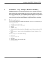
3.3
Installing USB drivers
Two USB drivers will be installed in two successive steps; one for USB and one for the
Ethernet emulation of USB. Follow these steps to install the USB drivers:
16 (87)
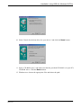
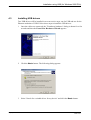
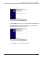
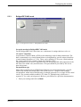
1
Once the cables are connected, the "New hardware found" dialog is shown for a few
seconds and then the Add New Hardware Wizard appears:
2
Click the Next> button. The following dialog appears:
3
Select "Search for the best driver for your device" and click the Next> button.
EN/LZT1083982 R4
2000-12-07
Installation using USB (for Windows 98 PCs)
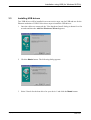
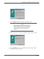
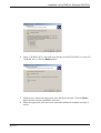
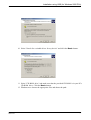
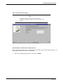
4
Select "CD-ROM drive" and make sure that the provided CD-ROM is in your PCs
CD-ROM drive. Click the Next> button.
5
Windows now locates the appropriate files and shows the path. Click the Next>
button and the software installation will start.
When the appropriate files have been copied the installation complete message is
shown:
6
EN/LZT1083982 R4
2000-12-07
17 (87)
Installation using USB (for Windows 98 PCs)
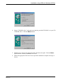
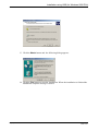
8
Click the Finish button. Windows 98 will now continue to the next phase of the
installation.
The "New hardware found" dialog is now shown for a few seconds and then the Add
New Hardware Wizard starts searching once again for the new driver for "Ericsson
HM220d Virtual NIC":
9
Click the Next> button. The following dialog appears:
7
18 (87)
EN/LZT1083982 R4
2000-12-07
Installation using USB (for Windows 98 PCs)
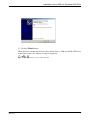
10 Select "Search for the best driver for your device" and click the Next> button.
11 Select "CD-ROM drive" and make sure that the provided CD-ROM is in your PCs
CD-ROM drive. Click the Next> button.
12 Windows now locates the appropriate files and shows the path:
EN/LZT1083982 R4
2000-12-07
19 (87)
Installation using USB (for Windows 98 PCs)
13 Click the Next> button and the software installation will start.
Note:
At this point there may be a need for you to insert the
Windows installation CD. This CD was included in the
original package of your PC and you used it to set up your
system. There may be a need to install some Microsoft
network components on the PC from the Windows
iinstallation CD. Insert the CD in the disk drive if
prompted.
14 When all files have been copied the installation complete message is shown:
15 Click the Finish button. The "System Settings Change" dialog will appear.
16 Click Yes to restart your computer.
20 (87)
EN/LZT1083982 R4
2000-12-07
Installation using USB (for Windows 98 PCs)
When the driver installation has been done and the Power, USB and ADSL LEDs have
turned solid yellow, the modem is ready for operation.
Figur 16: LED symbols for Power, USB and ADSL
EN/LZT1083982 R4
2000-12-07
21 (87)
Installation using USB (for Windows 98 PCs)
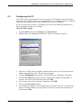
3.4
Configuring the PC
To be able to access the modem's built in web pages, the IP address for the PC must be
on the same IP net as the modem. A recommended way is to configure the PC as a DHCP
client and use the DHCP server in the modem to get a correct IP address.
If you are unsure how your PC is configured you can use the following instructions to
check, and maybe change, your settings.
Check TCP/IP settings:
1
From the Start menu select Settings then Control Panel.
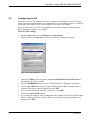
2
Double click on the Network icon and the "Network" dialog box appears:
Figur 17: Network dialog box
3
Select the TCP/IP protocol togheter with Ericsson HM220d Virtual NIC driver
according to the above example.
4
5
Click the Properties button and the "TCP/IP Properties" dialog box will appear.
Select the IP Address tab and verify that "Obtain and IP address automatically" is
selected. If not, then select this button and click OK.
You are now back in the "Network" dialog box. Click OK.
Close the Control Panel window.
If you made any changes, some configuration files might be copied on your hard disk
and if a "Settings Changes" message asks if you wish to restart your computer you
should answer Yes.
6
7
8
22 (87)
EN/LZT1083982 R4
2000-12-07
Installation using USB (for Windows 98 PCs)
By following the next steps you can verify that your PC now has got a new IP address
from the modem's DHCP server.
Check IP configuration:
1
From the Start menu select Run... .
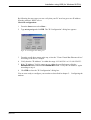
2
Type winipcfg and click OK. The "IP Configuration" dialog box appears:
Figur 18: IP Configuration dialog box
3
4
5
From the scroll down menu at the top, select the "Virata Virtual Bus Ethernet driver"
according to the above example.
Verify that the "IP Address" is within the range 192.168.254.1 to 192.168.254.253.
If the "IP Address" field is empty or not within the specified range, click the
Release All button and then the Renew All button. Verify the "IP Address" again
according to step 4.
6
Click OK to close the "IP Configuration" dialog box.
You are now ready to configure your modem as described in chapter 5 - Configuring the
modem.
EN/LZT1083982 R4
2000-12-07
23 (87)
Installation using USB (for Windows 2000 PCs)
4
Installation using USB (for Windows 2000 PCs)
This chapter describes the installation and configuration process using the USB interface
in Windows 2000 PCs.
Many computers today are shipped with a Universal Serial Bus (USB) port. With a USB
port, a Network Interface Card is not required, but a specific USB driver must be installed
on the computer. The USB driver required for the HM220d ADSL modem is provided on
the CD-ROM, and is installed during the installation phase. This driver facilitates
communication between the modem and the computer. Unlike an Ethernet connection, a
USB connection does not allow for more than one computer to be linked to the modem.
4.1
System requirements
To successfully connect and install the HM220d ADSL modem to the USB interface you
will need the following:
•
•
•
•
•
•
An ADSL-ready telephone line
133 MHz Processor and 16 MB RAM.
USB port
CD-ROM drive
Windows® 2000
Internet browser - Internet Explorer 4.06 (or higher) or Netscape Navigator 4.5 (or
higher).
From the package you will need the following:
•
•
•
•
•
24 (87)
The modem
Telephone/ADSL cable
USB cable
The power supply adapter with connecting cable
The CD-ROM disk.
EN/LZT1083982 R4
2000-12-07
Installation using USB (for Windows 2000 PCs)
4.2
Connecting equipment
To connect your HM220d ADSL modem via the USB interface, follow these steps:
1
2
3
Connect one end of the Telephone/ADSL cable to the modem's ADSL port and the
other end to the ADSL service port (wall jack or splitter/filter).
Connect the square plug of the USB cable to the USB port on the back of the modem
and connect the rectangular plug of the cable to the USB port on the back of your PC.
Connect the Power cable to the POWER connector on the back of the modem. Plug
the power supply adapter into a power source.
Figur 19: Connect via USB interface
4
Once the cables are connected, the PC will automatically search for the correct USB
driver, specific to your operating system.
Note:
The USB drivers are located on the CD-ROM disk that is
provided with the modem package. Insert the disk in your
PC's CD-ROM drive.
Follow the instructions in the next section to install the USB drivers.
EN/LZT1083982 R4
2000-12-07
25 (87)
Installation using USB (for Windows 2000 PCs)
4.3
Installing USB drivers
Two USB drivers will be installed in two successive steps; one for USB and one for the
Ethernet emulation of USB. Follow these steps to install the USB drivers:
26 (87)
1
Once the cables are connected, the "Found new hardware" dialog is shown for a few
seconds and then the Found New Hardware Wizard appears:
2
Click the Next> button. The following dialog appears:
3
Select "Search for a suitable driver for my device" and click the Next> button.
EN/LZT1083982 R4
2000-12-07
Installation using USB (for Windows 2000 PCs)
4
Select "CD-ROM drive" and make sure that the provided CD-ROM is in your PCs
CD-ROM drive. Click the Next> button.
5
Windows now locates the appropriate files and shows the path. Click the Next>
button and the software installation will start.
When the appropriate files have been copied the installation complete message is
shown:
6
EN/LZT1083982 R4
2000-12-07
27 (87)
Installation using USB (for Windows 2000 PCs)
7
8
9
28 (87)
Click the Finish button. Windows 2000 will now continue to the next phase of the
installation.
The "Found new hardware" dialog is now shown for a few seconds and then the
Found New Hardware Wizard starts once again:
Click the Next> button. The following dialog appears:
EN/LZT1083982 R4
2000-12-07
Installation using USB (for Windows 2000 PCs)
10 Select "Search for a suitable driver for my device" and click the Next> button.
11 Select "CD-ROM drive" and make sure that the provided CD-ROM is in your PCs
CD-ROM drive. Click the Next> button.
12 Windows now locates the appropriate files and shows the path:
EN/LZT1083982 R4
2000-12-07
29 (87)
Installation using USB (for Windows 2000 PCs)
13 Click the Next> button and the following dialog appears:
14 Click the Yes button to start the installation. When the installation is finished the
installation complete message is shown:
30 (87)
EN/LZT1083982 R4
2000-12-07
Installation using USB (for Windows 2000 PCs)
15 Click the Finish button.
When the driver installation has been done and the Power, USB and ADSL LEDs have
turned solid yellow, the modem is ready for operation.
Figur 31: LED symbols for Power, USB and ADSL
EN/LZT1083982 R4
2000-12-07
31 (87)
Installation using USB (for Windows 2000 PCs)
4.4
Configuring the PC
To be able to access the modem's built in web pages, the IP address for the PC must be
on the same IP net as the modem. A recommended way is to configure the PC as a DHCP
client and use the DHCP server in the modem to get a correct IP address.
If you are unsure how your PC is configured you can use the following instructions to
check, and maybe change, your settings.
Check TCP/IP settings:
1
From the Start menu select Settings then Control Panel.
2
3
Double click on the Network and Dial-up Connections. A new view appears
including icons for Local Area Connections.
Double click on the Local Area Connection icon for the Ericsson HM220d Virtual
NIC driver. If you have several icons be sure you choose the right one. The "Local
Area Connection Status" dialog box appears.
4
Click the Properties button to open the "Local Area Connection Properties" dialog
box:
Figur 32: Local Area Connection Properties dialog box
5
Select "Internet Protocol (TCP/IP)" according to the above example.
6
Click the Properties button and the "Internet Protocol (TCP/IP) Properties" dialog
box will appear.
Verify that "Obtain an IP address automatically" is selected. If not, then select this
button and click OK.
7
32 (87)
EN/LZT1083982 R4
2000-12-07
Installation using USB (for Windows 2000 PCs)
8
9
You are now back in the "Local Area Connection Properties" dialog box. Click OK.
Click Close in the "Local Area Connection Status" dialog box and close the
Network and Dial-up Connections window.
By following the next steps you can verify that your PC now has got a new IP address
from the modem's DHCP server.
Check IP configuration:
1
2
3
4
From the Start menu select Programs -> Accessories -> Command Prompt. The
"Command Prompt" window appears.
Type ipconfig and verify that the "IP Address" is within the range 192.168.254.1
to 192.168.254.253.
If the "IP Address" is not within the specified range, type ipconfig/release
and when the C:\> appears again type ipconfig/renew
Verify the "IP Address" again according to step 2.
Close the "Command Prompt" window.
Now you are ready to configure your modem as described in chapter 5 - Configuring the
modem.
EN/LZT1083982 R4
2000-12-07
33 (87)
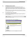
Configuring the modem
5
Configuring the modem
The configuration of the HM220d ADSL modem is done either by using the
Configuration Wizard or a flat structure. The Configuration Wizard is available in five
languages: English, Français, Deutsch, Español and Português. Everything is done by
using a web browser (Internet Explorer 4.01 or higher / Netscape Navigator 4.5 or higher)
and accessing the web-based, graphical interface that comes installed on the modem
itself.
The HM220d ADSL modem is shipped from the factory with particular default settings.
However, you may need to change some of them depending on what service your Internet
Service Provider (ISP) is providing.
5.1
Accessing the modem's web pages
Access the modem's web pages by starting your web browser and enter the IP address of
the modem - http://192.168.254.254 -in the "Location" or "Address" area where you
enter web page addresses.
Figur 33: Enter the IP address of the modem
The HM220d ADSL modem's "Welcome" page appears.
Figur 34: Welcome page
34 (87)
EN/LZT1083982 R4
2000-12-07
Configuring the modem
This is the opening page of the HM220d ADSL modem's local web pages.
Click on the Wizard button, in the left column, to start the Configuration Wizard
(available in five languages) which walks you through the configuration process step by
step (recommended the first time).
Use the Product Info and Status buttons to see views of the current status of the
modem and other product information. Described in section 5.6 - Product Information
and 5.7 - Status.
The Advanced Settings button will bring up a new window including all parameters
that can be set. This view can be used when reconfiguring the modem or just checking the
settings. Described in section 5.5 - Advanced settings.
•
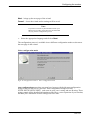
Click on the Wizard button to enter the Configuration Wizard.
Select language
Figur 35: Configuration wizard - Select language
This is the first page of the Configuration Wizard where you select which language English, Français, Deutsch, Español or Português - you wish the information to be
presented to you.
All pages in the Configuration Wizard have the same buttons at the bottom:
Help - brings up a help window
Back - takes you back to the previous page of the wizard
EN/LZT1083982 R4
2000-12-07
35 (87)
Configuring the modem
Next - brings up the next page of the wizard
Cancel - closes the wizard and no settings will be saved.
Note:
If you have received any documentation from your
ISP/service provider, please have this at hand when
carrying out the configuration process.
•
Select the appropriate language and click on Next.
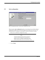
The configuration process is available in two different configuration modes as shown on
the next page in the wizard.
Select configuration mode
Figur 36: Configuration wizard - Select configuration mode
Auto configuration means that you must have been provided with auto configuration
strings from your ISP/service provider. Auto configuration strings look like
XXXX-XXXX-XXXX-XXXX and come in pairs; one A string and one B string. These
strings contain all the detailed information needed for a correct operation of your modem,
and then just a minimum of other settings has to be done.
36 (87)
EN/LZT1083982 R4
2000-12-07
Configuring the modem
Manual configuration should be used if auto configuration strings have not been
provided, which means that the configuration is done more or less manually. In this mode
you have to enter, or change, some more settings.
•
Select the appropriate configuration mode and then click Next.
The Auto configuration is described in the next section and the Manual configuration in
section 5.3 - Manual configuration.
EN/LZT1083982 R4
2000-12-07
37 (87)
Configuring the modem
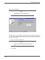
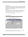
5.2
Auto configuration
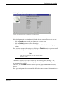
Figur 37: Configuration wizard - Enter the auto configuration strings
When using the Auto configuration mode you must have been provided with auto
configuration strings (one A and one B string) by your ISP/service provider. The
following pictures will guide you through the wizard and explain the settings.
•
Enter your A and B auto configuration strings.
Note:
You have to enter the strings exactly the way they are
written in the documentation from your ISP/service
provider, e.g. the "-"-characters must be entered. The
letters "l" and "O" are not placed in the strings, so any
character that looks like a zero is a zero and a one is a one.
•
38 (87)
Click on Next.
EN/LZT1083982 R4
2000-12-07
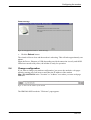
Configuring the modem
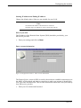
Enter account information
Note:
This page might not be shown depending on which
operating mode your service provider is using.
Figur 38: Configuration wizard - Enter account information
The Point-to-Point protocol (PPP) is used by the modem to establish connections over
the ADSL ATM network and when a connection is made your account is identified by
your User name and Password. This account information should have been provided by
your ISP/service provider.
•
Enter your User Name and Password.
Note:
You have to enter your User name and Password exactly as
provided, i.e. distinguish between uppercase and lowercase
letters.
•
EN/LZT1083982 R4
2000-12-07
Click on Next.
39 (87)
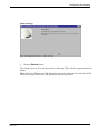
Configuring the modem
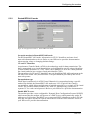
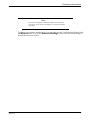
Finishing the modem setup
Figur 39: Configuration wizard - Finishing the modem setup
This is the last page in the wizard and it includes all your settings. Review the list and:
•
click the Back button to make any changes on previous pages
•
click the Finish button to confirm all settings
•
click the Cancel button to close the Configuration Wizard without saving any
settings.
When you have accepted the settings (by clicking the Finish button) the parameters will
be set and a check is performed that their values are correct.
Note:
This will take a while, but just wait until the "Status
message" appears.
If anything is incorrect you will be notified by the following status message: "The
parameters could not be altered according to your changes. Check the settings and consult
the documentation for help".
In that case, use the Back button to return to previous pages and make the necessary
changes.
When your settings have been accepted the following status message is shown (picture on
next page): "The parameters have been set. Press 'Reboot' to reboot the modem".
40 (87)
EN/LZT1083982 R4
2000-12-07
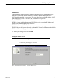
Configuring the modem
Status message
Figur 40: Configuration wizard - Status message
•
Click the Reboot button.
The wizard will now close and the modem is rebooting. This will take approximately one
minute.
When the Power, Ethernet or USB (depending on which connection is used), and ADSL
LEDs have turned solid yellow, the modem is ready for operation.
EN/LZT1083982 R4
2000-12-07
41 (87)
Configuring the modem
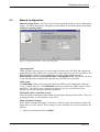
5.3
Manual configuration
Manual configuration is used if you have not been provided with any auto configuration
strings. The following pictures will guide you through the wizard and explain the settings.
Select the operating mode
Figur 41: Configuration wizard - Select operating mode
Operating mode
ADSL modems operate in one of several modes determined by the DSLAM (equipment
at the ISP side of the ADSL line), central office setup and also by the service offered. The
HM220d ADSL modem can be configured to operate in three different modes:
Routed/PPPoA (default), Routed/RFC1483 or Bridged/RFC1483. Which one you need
to use depends on the configuration specified by your ISP/service provider.
ADSL mode
The HM220dp modem can work in four different ADSL modes: Multimode (default),
T1.413, G.Dmt and G.Lite. The HM220di model can work in two ADSL modes: G.Dmt
and DTAG. The ADSL-mode depends on what services you are offered and your
ISP/service provider must provide this information.
Modem IP address and Subnet mask
These IP addresses belongs to the modem itself and have factory default values. They can
be changed if they are not suitable in your LAN.
Make customized settings
If the "Make customized settings?" checkbox is ticked, a page with optional settings will
appear later on in the wizard. These settings are not required to be set for operation of the
modem.
•
42 (87)
Enter your settings and click on Next.
EN/LZT1083982 R4
2000-12-07
Configuring the modem
If you have chosen the Routed/PPPoA mode, continue reading the next section. For
Routed/RFC1483 mode, go on to section 5.3.2 and for Bridged/RFC183 mode, go on to
section 5.3.3.
EN/LZT1083982 R4
2000-12-07
43 (87)
Configuring the modem
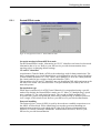
5.3.1
Routed/PPPoA mode
Figur 42: Configuration wizard - Routed/PPPoA mode
Set up the modem in Routed/PPPoA mode
For the Routed/PPPoA mode, information on VP/VC identifiers and some local network
information has to be set. Refer to your ISP/service provider documentation when
entering values or changing default settings.
VP and VC identifiers
Asynchronous Transfer Mode (ATM) is the technology used for data transmission. The
data is transmitted over virtual channels that are designated by specific unique identifiers
(virtual channel identifiers or VCIs). There can be multiple VCIs in one virtual path and
the virtual path also has a unique virtual path identifier (VPI).
The parameters for VP and VC should be one pair identifying DSLAM (equipment at the
ISP side of the ADSL line) and ISP router. This pair should be provided by the access
network operator.
Encapsulation type
When data is transferred via ATM Virtual Channels it is encapsulated using a specific
method. By default, the Routed/PPPoA mode uses VC Mux (VC Multiplexing), which
uses a separate VC for each carried protocol. The second available method is LLC
(Logical Link Control) encapsulation, which allows multiplexing of multiple protocols
over a single ATM virtual circuit. Refer to your ISP/service provider documentation.
Password handling
The Point-to-Point protocol (PPP) is used by the modem to establish connections over
the ADSL ATM network. When identifying your modem (password handling) an
authentication protocol is used which can be either PAP (Password Authentication
Protocol) or CHAP (Challenge-Handshake Authentication Protocol). Refer to your
ISP/service provider documentation.
44 (87)
EN/LZT1083982 R4
2000-12-07
Configuring the modem
Enable DHCP server
The modem provides a user-configurable Dynamic Host Configuration Protocol (DHCP)
which means that the modem will operate as a DHCP server and dynamically assign IP
addresses to LAN nodes. The DHCP server supports DHCP client hosts on the LAN side
only and will ignore all DHCP requests which arrive from the WAN interface. Refer to
your ISP/service provider documentation.
Enable NAT
The modem also supports Network Address Translation (NAT) which translates IP
addresses from private internal addresses to globally unique external addresses.
NAT should be enabled for most users. For users who have a public IP address, NAT
may be disabled. If you are not sure, ask your ISP/service provider.
•
Enter your settings and click on Next.
Set up the DHCP server
Note:
This page is only shown if you selected "Enable DHCP
server" on the previous page in the wizard.
Figur 43: Configuration wizard - Set up the DHCP server
The DHCP server supplies IP addresses on your local network. You have to supply a
range of numbers that the modem can hand out to your computer.
EN/LZT1083982 R4
2000-12-07
45 (87)
Configuring the modem
Starting IP address and Ending IP address
Change the default values if they are not suitable for your LAN.
Note:
The "Modem IP address" MUST NOT be within the
specified range, but MUST be on the same IP sub network.
DNS of your ISP
The IP address of the Domain Name System (DNS) should be provided by your
ISP/service provider.
•
Enter your settings and click on Next.
Enter account information
Figur 44: Configuration wizard - Enter account information
The Point-to-Point protocol (PPP) is used by the modem to establish connections over
the ADSL ATM network and when a connection is made your account is identified by
your User name and Password. This account information should have been provided by
your ISP/service provider.
•
46 (87)
Enter your User name and Password.
EN/LZT1083982 R4
2000-12-07
Configuring the modem
Note:
You have to enter your User name and Password exactly as
provided, i.e. distinguish between uppercase and lowercase
letters.
•
Click on Next.
Alter the customized settings
Note:
This page is only shown if you ticked the "Make
customized settings?" checkbox on a previous page in the
wizard.
Figur 45: Configuration wizard - Alter the customized settings
System name, Location and Contact person
The system information are for identifying your modem, when accessing it remotely, e.g.
with support from your ISP/service provider.
•
EN/LZT1083982 R4
2000-12-07
Enter your identifying parameters and click on Next.
47 (87)
Configuring the modem
Finishing the modem setup
Figur 46: Configuration wizard - Finishing the modem setup
This is the last page in the wizard and it includes all your settings. Review the list and:
•
click the Back button to make any changes to previous pages
•
click the Finish button to confirm all settings
•
click the Cancel button to close the Configuration Wizard without saving any
settings.
When you have accepted the settings (by clicking the Finish button) the parameters will
be set and a check is performed that their values are correct.
Note:
This will take a while, but just wait until the "Status
message" appears.
If anything is incorrect you will be notified by the following status message: "The
parameters could not be altered according to your changes. Check the settings and consult
the documentation for help".
In that case, use the Back button to return to previous pages and make the necessary
changes.
When your settings have been accepted the following status message is shown (picture on
next page): "The parameters have been set. Press 'Reboot' to reboot the modem".
48 (87)
EN/LZT1083982 R4
2000-12-07
Configuring the modem
Status message
Figur 47: Configuration wizard - Status message
•
Click the Reboot button.
The wizard will now close and the modem is rebooting. This will take approximately one
minute.
When the Power, Ethernet or USB (depending on which connection is used), and ADSL
LEDs have turned solid yellow, the modem is ready for operation.
EN/LZT1083982 R4
2000-12-07
49 (87)
Configuring the modem
5.3.2
Routed/RFC1483 mode
Figur 48: Configuration wizard - Routed/RFC1483 mode
Set up the modem in Routed/RFC1483 mode
For the Routed/RFC1483 mode, information on VP/VC identifiers and some local
network information has to be set. Refer to your ISP/service provider documentation
when entering values or changing default settings.
VP and VC identifiers
Asynchronous Transfer Mode (ATM) is the technology used for data transmission. The
data is transmitted over virtual channels that are designated by specific unique identifiers
(virtual channel identifiers or VCIs). There can be multiple VCIs in one virtual path and
the virtual path also has a unique virtual path identifier (VPI).
The parameters for VP and VC should be one pair identifying DSLAM (equipment at the
ISP side of the ADSL line) and ISP router. This pair should be provided by the access
network operator.
Encapsulation type
When data is transferred via ATM Virtual Channels it is encapsulated using a specific
method. By default, the Routed/RFC1483 mode uses LLC (Logical Link Control)
encapsulation, which allows multiplexing of multiple protocols over a single ATM virtual
circuit. The second available method is VC Mux (VC Multiplexing), which uses a
separate VC for each carried protocol. Refer to your ISP/service provider documentation.
Enable DHCP server
The modem provides a user-configurable Dynamic Host Configuration Protocol (DHCP)
which means that the modem will operate as a DHCP server and dynamically assign IP
addresses to LAN nodes. The DHCP server supports DHCP client hosts on the LAN side
only and will ignore all DHCP requests which arrive from the WAN interface. Refer to
your ISP/service provider documentation.
50 (87)
EN/LZT1083982 R4
2000-12-07
Configuring the modem
Enable NAT
The modem also supports Network Address Translation (NAT) which translates IP
addresses from private internal addresses to globally unique external addresses.
NAT should be enabled for most users. For users who have a public IP address, NAT
may be disabled. If you are not sure, ask your ISP/service provider.
Enable DHCP client
If DHCP client is enabled the modems DHCP client will request the IP address and
subnet mask for the modems WAN interface.
WAN IP address and WAN subnet mask
The IP address and subnet mask for the modems WAN interface. The values should be
specified by your ISP/service provider. (If the DHCP client is enabled these parameters
will be set automatically by the modem).
•
Enter your settings and click on Next.
Set up the DHCP server
Note:
This page is only shown if you selected "Enable DHCP
server" on the previous page in the wizard.
Figur 49: Configuration wizard - Setup the DHCP server
EN/LZT1083982 R4
2000-12-07
51 (87)
Configuring the modem
The DHCP server supplies IP addresses on your local network. You have to supply a
range of numbers that the modem can hand out to your computer.
Starting IP address and Ending IP address
Change the default values if they are not suitable for your LAN.
Note:
The "Modem IP address" MUST NOT be within the
specified range, but MUST be on the same IP sub network.
DNS of your ISP
The IP address of the Domain Name System (DNS) should be provided by your
ISP/service provider.
•
Enter your settings and click on Next.
Alter the customized settings
Note:
This page is only shown if you ticked the "Make
customized settings?" checkbox on a previous page in the
wizard.
Figur 50: Configuration wizard - Alter the customized settings
52 (87)
EN/LZT1083982 R4
2000-12-07
Configuring the modem
System name, Location and Contact person
The system information are for identifying your modem, when accessing it remotely, e.g.
with support from your ISP/service provider.
•
Enter your identifying parameters and click on Next.
Finishing the modem setup
Figur 51: Configuration wizard - Finishing the modem setup
This is the last page in the wizard and it includes all your settings. Review the list and:
•
click the Back button to make any changes to previous pages
•
click the Finish button to confirm all settings
•
click the Cancel button to close the Configuration Wizard without saving any
settings.
When you have accepted the settings (by clicking the Finish button) the parameters will
be set and a check is performed that their values are correct.
EN/LZT1083982 R4
2000-12-07
53 (87)
Configuring the modem
Note:
This will take a while, but just wait until the "Status
message" appears.
If anything is incorrect you will be notified by the following status message: "The
parameters could not be altered according to your changes. Check the settings and consult
the documentation for help".
In that case, use the Back button to return to previous pages and make the necessary
changes.
When your settings have been accepted the following status message is shown (picture on
next page): "The parameters have been set. Press 'Reboot' to reboot the modem".
Status message
Figur 52: Configuration wizard - Status message
•
Click the Reboot button.
The wizard will now close and the modem is rebooting. This will take approximately one
minute.
When the Power, Ethernet or USB (depending on which connection is used), and ADSL
LEDs have turned solid yellow, the modem is ready for operation.
54 (87)
EN/LZT1083982 R4
2000-12-07
Configuring the modem
5.3.3
Bridged/RFC1483 mode
Figur 53: Configuration wizard - Bridged/RFC1483 mode
Set up the modem in Bridged/RFC1483 mode
For the Bridged/RFC1483 mode there are a minimum of settings that have to be set.
VP and VC identifiers
Asynchronous Transfer Mode (ATM) is the technology used for data transmission. The
data is transmitted over virtual channels that are designated by specific unique identifiers
(virtual channel identifiers or VCIs). There can be multiple VCIs in one virtual path and
the virtual path also has a unique virtual path identifier (VPI).
The parameters for VP and VC should be one pair identifying DSLAM (equipment at the
ISP side of the ADSL line) and ISP router. This pair should be provided by the access
network operator.
Encapsulation type
When data is transferred via ATM Virtual Channels it is encapsulated using a specific
method. By default, the Bridged/RFC1483 mode uses LLC (Logical Link Control)
encapsulation, which allows multiplexing of multiple protocols over a single ATM virtual
circuit. The second available method is VC Mux (VC Multiplexing), which uses a
separate VC for each carried protocol. Refer to your ISP/service provider documentation.
•
EN/LZT1083982 R4
2000-12-07
Enter your settings and click on Next.
55 (87)
Configuring the modem
Alter the customized settings
Note:
This page is only shown if you ticked the "Make
customized settings?" checkbox on a previous page in the
wizard.
Figur 54: Configuration wizard - Alter the customized settings
System name, Location and Contact person
The system information are for identifying your modem, when accessing it remotely, e.g.
with support from your ISP/service provider.
•
56 (87)
Enter your identifying parameters and click on Next.
EN/LZT1083982 R4
2000-12-07
Configuring the modem
Finishing the modem setup
Figur 55: Configuration wizard - Finishing the modem setup
This is the last page in the wizard and it includes all your settings. Review the list and:
•
click the Back button to make any changes to previous pages
•
click the Finish button to confirm all settings
•
click the Cancel button to close the Configuration Wizard without saving any
settings.
When you have accepted the settings (by clicking the Finish button) the parameters will
be set and a check is performed that their values are correct.
Note:
This will take a while, but just wait until the "Status
message" appears.
If anything is incorrect you will be notified by the following status message: "The
parameters could not be altered according to your changes. Check the settings and consult
the documentation for help".
In that case, use the Back button to return to previous pages and make the necessary
changes.
When your settings have been accepted the following status message is shown (picture on
next page): "The parameters have been set. Press 'Reboot' to reboot the modem".
EN/LZT1083982 R4
2000-12-07
57 (87)
Configuring the modem
Status message
Figur 56: Configuration wizard - Status message
•
Click the Reboot button.
The wizard will now close and the modem is rebooting. This will take approximately one
minute.
When the Power, Ethernet or USB (depending on which connection is used), and ADSL
LEDs have turned solid yellow, the modem is ready for operation.
5.4
Change configuration
If you want to change your modem configuration, just access the modem's web pages
again by starting your web browser and enter the IP address of the modem
http://192.168.254.254 in the "Location" or "Address" area where you enter web page
addresses.
Figur 57: Enter the IP address of the modem
The HM220d ADSL modem's "Welcome" page appears.
58 (87)
EN/LZT1083982 R4
2000-12-07
Configuring the modem
Note:
If you have changed the default IP address of the modem,
you have to enter the new IP address to access the modem's
web pages.
To change your modem configuration, you can either use the Configuration Wizard (click
the Wizard button) or select the Advanced Settings button. The Advanced settings is
described in the next section.
EN/LZT1083982 R4
2000-12-07
59 (87)
Configuring the modem
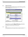
5.5
Advanced settings
Instead of going through the Configuration Wizard, you have the option to view all the
parameters that can be changed in one view. From the modem's Welcome page, click the
Advanced Settings button to bring up this view:
Figur 58: Advanced settings
This view includes two new buttons - Save and Cancel. When you have made any
changes and want to save them, use the Save button. The Cancel button will restore
your settings to its former state and no changes will be saved.
The information is divided into sections, as described below.
5.5.1
60 (87)
LAN
The "Modem IP address" and "Subnet mask" belong to the modem. The parameters have
default settings and should only be changed if these are not suitable in your LAN.
EN/LZT1083982 R4
2000-12-07
Configuring the modem
ADSL modems operate in one of serveral modes determined by the DSLAM (equipment
at the ISP side of the ADSL line), central office setup and also by service offered. The
HM220d ADSL modem can be configured to operate in three different "Operating
modes": Routed/PPPoA (default), Routed/RFC1483 or Bridged/RFC1483. Which one
you need to use depends on the configuration specified by your ISP/service provider.
The "ADSL mode" depends on what services you are offered and your ISP/service
provider must provide this information. The HM220dp model can work in four different
ADSL modes which are Multimode (default), T1.413, G.Dmt, and G.Lite. The HM220di
model can work in two different ADSL modes which are G.Dmt and DTAG.
5.5.2
Routed
This section is only shown if either "Routed/PPPoA" or "Routed/RFC1483" operating
mode is selected in the previous LAN section.
The information differs some between the Routed/PPPoA and Routed/RFC1483 mode.
Password handling, User name and Password is only valid for Routed/PPPoA mode.
DHCP client, WAN IP address and WAN Subnet mask are used in Routed/RFC1483
mode.
When the modem operates in Routed mode it sends packets from node to node based on
IP addresses. An IP address can be viewed as a modifiable identifier that is mapped to the
MAC address of network node. The IP address of a node may change dynamically or by
user configuration. Therefore, there are protocols and databases on the network that must
keep track of the IP address assignments for the nodes on the local area network (LAN).
For the Routed mode, information on VP/VC identifiers and some local network
information has to be set.
The "VP and VC identifiers" refer to the technology, Asynchronous Transfer Mode,
ATM, used for data transmission. The data is transmitted over virtual channels that are
designated by specific unique identifiers (Virtual Channel Identifiers or VCIs). There can
be multiple VCIs in one virtual path and the virtual path also has a unique Virtual Path
Identifier, VPI.
The parameters for VP and VC should be one pair identifying DSLAM (equipment at the
ISP side of the ADSL line) and ISP router. This pair should be provided by the access
network operator.
"Encapsulation type" is the specific method used when data is transferred via ATM
Virtual Channels. For Routed/PPPoA operating mode, the default value for the modem is
VC Mux (VC Multiplexing), which uses a separate VC for each carried protocol. For
Routed/RFC1483 operating mode the default value is LLC (Logical Link Control)
encapsulation, which allows multiplexing of multiple protocols over a single ATM virtual
circuit. Refer to your ISP/service provider documentation.
Password handling refers to the Point-to-Point protocol (PPP) which is used by the
modem to establish connections over the ADSL ATM network. When identifying your
modem (password handling) an authentication protocol is used which can be either PAP
(Password Authentication Protocol) or CHAP (Challenge-Handshake Authentication
Protocol). Refer to your ISP/service provider documentation.
EN/LZT1083982 R4
2000-12-07
61 (87)
Configuring the modem
The modem also supports Network Address Translation (NAT) which translates IP
addresses from private internal addresses to globally unique external addresses. NAT
should be enabled for most users. For users who have a public IP address, NAT may be
disabled. If you are not sure, ask your ISP/service provider.
If "DHCP client" is enabled the modem's DHCP client will request the IP address and
subnet mask for the WAN interface. Removing the need to manually configure those
parameters.
If "DHCP client" is not enabled the WAN IP address and Subnet mask have to be set
manually. The parameters should be provided by your ISP/service provider.
"User name" and "Password" should be provided by your ISP/service provider. This is
your account information that identifies your modem when a connection is made.
5.5.3
DHCP
This section is only shown if either "Routed/PPPoA" or "Routed/RFC1483" operating
mode is selected in the previous LAN section.
The modem provides a user-configurable Dynamic Host Configuration Protocol (DHCP)
which means that the modem will operate as a DHCP server and dynamically assign IP
addresses to LAN nodes. The DHCP server supports DHCP client hosts on the LAN side
only and will ignore all DHCP requests which arrive from the WAN interface.
You have to supply a range of addresses (Starting IP address and Ending IP address) that
the modem can hand out to your computer.
Note:
The "Modem IP address" MUST NOT be within the
specified range, but MUST be on the same IP sub network.
The IP address of the Domain Name System (DNS) should be provided by your
ISP/service provider.
62 (87)
EN/LZT1083982 R4
2000-12-07
Configuring the modem
5.5.4
Bridged
This section is only shown if "Bridged/RFC1483" operating mode is selected in the
previous LAN section.
When the modem operates in Bridged mode, it is the MAC address of the sending and
receiving computers or devices (nodes) on the network that determine where to send data
packets between LAN segments. The MAC address is a unique identifier that is
programmed into the network interface card installed in a network node. Bridging is a
simple transmission scheme and there is little software management involved in the
sending of packets. Packets are simply forwarded from one node to the next.
For the Bridged/RFC1483 mode, only a minimum of parameters have to be set.
The "VP and VC identifiers" refers to the technology, Asynchronous Transfer Mode,
ATM, used for data transmission. The data is transmitted over virtual channels that are
designated by specific unique identifiers (Virtual Channel Identifiers or VCIs). There can
be multiple VCIs in one virtual path and the virtual path also has a unique Virtual Path
Identifier, VPI.
The parameters for VP and VC should be one pair identifying DSLAM (equipment at the
ISP side of the ADSL line) and ISP router. This pair should be provided by the access
network operator.
"Encapsulation type" is the specific method used when data is transferred via ATM
Virtual channels. For Bridged/RFC1483 operating mode, the default value for the modem
is LLC (Logical Link Control) encapsulation, which allows multiplexing of multiple
protocols over a single ATM virtual circuit. The second available method is VC Mux
(VC Multiplexing), which uses a separate VC for each carried protocol. Refer to your
ISP/service provider documentation.
5.5.5
Customized
The customized settings contain information on "System name", "System location" and
"System contact person". This system information is used for identifying your modem
when accessing it remotely, e.g. with support from your ISP/service provider.
5.5.6
Management
The OAM, Operation and Maintenance capability in the ADSL modem provides
Performance and Fault management for the ATM network connections. The HM220d
ADSL modem provides support for OAM Loopback cells, Fault Management and
Continuous continuity monitoring. The OAM support is provided both on Virtual Paths
(OAM F4 Table) and Virtual Channels (OAM F5 Table). The settings for the OAM
parameters should be defined by the ISP/service provider.
The ATM Forum ILMI protocol support exchange of configuration information between
interconnected ATM devices, such as an ADSL modem and a DSLAM. The setting for
this parameter should be defined by the ISP/service provider.
The trap destination IP is the IP address to where the modem should send the SNMP
trap messages. The setting for this parameter should be defined by the ISP/service
provider.
EN/LZT1083982 R4
2000-12-07
63 (87)
Configuring the modem
5.6
Product Information
From the modem's Welcome page, click the Product Info button to get the following
view:
Figur 59: Product information
This page contains information on your HM220d modem and the ADSL site at the ISP.
64 (87)
EN/LZT1083982 R4
2000-12-07
Configuring the modem
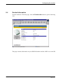
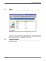
5.7
Status
From the modem's Welcome page, click the Status button to get the following view:
Figur 60: Status
This view gives you the current status of the ADSL interface. Click on the links below
the table to get the status of the different modem interfaces. The parameters shown and
the different interface views are updated every 10th second.
5.8
Update the software
Ericsson will keep you updated with the latest technology, and let you download the
latest software update.
EN/LZT1083982 R4
2000-12-07
65 (87)
Operation
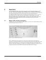
6
Operation
Once the HM220d ADSL modem has been properly connected and configured, simply
open your Internet browser and you are instantly on-line. No logon procedures are
necessary. The modem should be left on at all times; there is no need to turn it on and off,
since PipeLock guarantees your security when you are not using the Internet.
The HM220d ADSL modem operates automatically and will rarely, if ever, require any
intervention from you. There are some special features of the modem, such as the
PipeLock, with which you should be familiar. You may also want to know more about
the modem LEDs, which indicate the current operating state and provide useful
diagnostic information.
6.1
Modem LED indicator description
Looking at the top of the HM220d ADSL modem, you will see five light-emitting diodes
(LEDs) along the left side of the unit.
Figur 61: LEDs on HM220d ADSL modem
These LEDs indicate the current state of the modem and provide useful diagnostic
information. Although the functions of the LEDs depend upon the operational state of the
modem, the general purpose of each is described in the table below. Each LED can be
ON (lit), OFF (unlit), flashing at a certain rate or blinking periodically to indicate activity.
The general purpose of each LED is described in the table on the next page.
66 (87)
EN/LZT1083982 R4
2000-12-07
Operation
Symbol
Text
Description
Power
The Power LED indicates whether or not there is power to the modem.
USB
The USB LED indicates the status of the link (USB) between the modem
and your computer.
After the Power-up Diagnostics and Initialization have completed, the
LED will turn solid yellow,
and then begin to flash yellow when there is activity on the link.
Ethernet
The Ethernet LED indicates the status of the link (Ethernet) between the
modem and your
computer. After the Power-up Diagnostics and Initialization have
completed, the LED will turn
solid yellow, and then begin to flash yellow when Ethernet traffic is
flowing.
ADSL
The ADSL LED will flash yellow while the DSL line is training to get the
optimum transmission
rate. When the line is trained, the LED turns solid yellow.
PipeLock
The PipeLock LED indicates whether or not the PipeLock feature is
currently activated.
Tabell 2: Description of LEDs on HM220d ADSL modem
6.2
PipeLock
Ericsson's unique PipeLock technology enables you to suspend communication between
the modem and your computer with the touch of a button. This provides added security
when the modem is not in use. When PipeLock is activated, the modem remains logged
on, but direct communication between your computer and your service provider is
blocked. Since PipeLock does not interrupt communication between the modem and the
service provider network, a second touch of the button instantly restores communication.
To activate PipeLock, simply press the PipeLock button located to the right on top of
the modem.
Figur 62: PipeLock button
EN/LZT1083982 R4
2000-12-07
67 (87)
Operation
Press the button again to instantly regain Internet access. The PipeLock LED will indicate
whether PipeLock is activated (LED lit) or not (LED unlit) at any time.
Figur 63: PipeLock LED symbol
The PipeLock status will be retained if the modem is reset or if the power is interrupted.
That is, if PipeLock is activated just prior to a power interruption or reset, it will return to
the active state when the power-up diagnostics are complete.
6.3
Operational states
As the HM220d ADSL modem is powered up and goes through its startup and operation
phases, there are a number of different operational states that it may pass through. Each
of these states and its associated LEDs are described in the following sections.
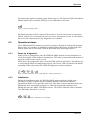
6.3.1
Power-up diagnostics
In the Power-up Diagnostics state, the HM220d ADSL modem executes diagnostics to
verify the integrity of the hardware and software. This state is entered when the modem is
first powered up or after a power cycle.
When Power-up Diagnostics starts, all of the LEDs will turn ON briefly. This allows you
to verify that all LEDs are functioning properly. The Power LED will remain ON and the
remaining LEDs will remain OFF while the diagnostics routine completes.
Figur 64: LED symbols for Power, USB, Ethernet, ADSL and PipeLock
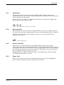
6.3.2
Initialization
During the Initialization state, the HM220d ADSL modem performs all the steps
necessary to register with the system, including finding a downstream channel,
registering with the service provider, and so on. This state is entered when the Power-up
Diagnostics state successfully completes or when the downstream channel is lost.
During this state, the ADSL LED flashes slowly. The USB or Ethernet LED is normally
ON, and blinks when there is activity.
Figur 65: LED symbols for USB, Ethernet and ADSL
68 (87)
EN/LZT1083982 R4
2000-12-07
Operation
6.3.3
Operational
The Operational state is entered when the HM220d ADSL modem completes the
initialization process and is ready to begin sending and receiving data. This is the normal
state of operation for the modem.
During this state, the ADSL and USB/Ethernet LEDs are normally ON, flashing when
there is activity on the respective link.
Figur 66: LED symbols for USB, Ethernet and ADSL
6.3.4
PipeLock mode
When PipeLock is activated, it blocks communication between your computer and your
service provider, thus preventing outsiders from accessing information on your computer.
The PipeLock LED is ON when the PipeLock feature is activated and OFF when
PipeLock is deactivated.
Figur 67: PipeLock LED symbol
6.3.5
Access restricted
When in the Access Restricted state, the HM220d ADSL modem will complete
initialization and respond to Management traffic, but will not allow data transfer between
your computer and your service provider. This is an indication that the service provider is
not allowing your modem on the system. When the LEDs indicate an Access Restricted
state, you should contact your service provider.
During this state, the ADSL LED flashes slowly. The USB/Ethernet LED is normally
ON, and blinks when there is activity.
6.3.6
Power cycle
When a fatal error has occurred you should perform a power cycle by unplugging the
power connector and then reconnect it again after 30 seconds.
EN/LZT1083982 R4
2000-12-07
69 (87)
Technical reference
7
Technical reference
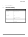
7.1
Factory default configuration
The table below shows the default settings of your modem.
Configurable item
Default settings
Operating mode
Routed/PPPoA
Ethernet interface
IP address: 192.168.254.254
Subnet mask: 255.255.255.0
VP/VC identifiers
None (operator specific)
Encapsulation type
VC Mux
Password handling
CHAP
DHCP server
Enabled
Starting IP address: 192.168.254.1
Ending IP address: 192.168.254.253
NAT
Enabled
DNS
None (operator specific)
ADSL mode
Multimode (HM220dp)
G.Dmt (HM220di)
70 (87)
EN/LZT1083982 R4
2000-12-07
Technical reference
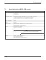
7.2
Specification of the HM220d ADSL modem
Description
Dimensions
Height: 47 mm
Width: 168 mm
Depth: 205 mm
Environment (climat)
Normal operating range: Temperature ±0 to +40oC. Humidity 5 to 90% RH
Transport: Temperature -40 to +70oC. Humidity 5 to 100% RH.
Storage: Temperature -25 to +55oC. Humidity 5 to 100% RH.
Power consumption
9 Watts
Colour
Off white
ADSL Standards
HM220dp (POTS) - Multimode, T1.413, G.Dmt and G.Lite.
HM220di (ISDN) - G.Dmt and DTAG
Bit rate
Downstream: up to 8 Mbps
Upstream: up to 864 kbps
Note:
Service provider may limit available bandwidth.
Interfaces
Ethernet: 10 Base-T RJ45 connector
USB: USB Series B connector
ADSL: Standard RJ11 telephone connector
EN/LZT1083982 R4
2000-12-07
71 (87)
Trouble shooting
8
Trouble shooting
8.1
Configuring your PC when not using DHCP
When accessing the modem's built-in web pages and the Configuration wizard, your
computer should be configured to use DHCP as described in previous sections.
If your settings, according to information from your ISP/service provider, does not
include the use of DHCP you have to reconfigure your PC again before you can access
the modem.
Follow the step-by-step instructions below to configure your computer to not using
DHCP.
Installation using Ethernet in Windows 95 (or higher) or USB in Windows 98:
1
From the Start menu select Settings -> Control panel. The "Control Panel" dialog
box will appear.
2
Double-click on the Network icon and the "Network" dialog box will appear.
Ethernet installation
72 (87)
USB installation (Windows 98)
3
Select the TCP/IP protocol according to the pictures above.
4
Click the Properties button and the "TCP/IP Properties" dialog box will appear.
EN/LZT1083982 R4
2000-12-07
Trouble shooting
5
Select the IP Address tab and select Specify and IP address.
6
7
8
9
Enter the IP address and Subnet mask and click on OK.
You are now back in the "Network" dialog box. Click OK.
Close the Control Panel window.
Some configuration files might be copied onto your hard disk and if a "Setting
Changes" message asks you if you wish to restart your computer you should answer
Yes.
Installation using USB in Windows 2000:
1
2
3
4
From the Start menu select Settings -> Control Panel.
Double click on the Network and Dial-up Connections. A new view appears
including icons for Local Area Connections.
Double click the Local Area Connection icon for the Ericsson HM220d Virtual
NIC driver. If you have several icons be sure you choose the right one. The "Local
Area Connection Status" dialog box appears.
Click the Properties button to open the "Local Area Connection Properties" dialog
box:
Figur 68: Local Area Connection Properties
5
Select "Internet Protocol (TCP/IP)" according to the above example.
6
Click the Properties button and the "Internet Protocol (TCP/IP) Properties" dialog
box will appear.
Select "Specify and IP address" and enter the IP addresses specified by your
ISP/service provider. Click OK.
You are now back in the "Local Area Connection Properties" dialog box. Click OK.
7
8
EN/LZT1083982 R4
2000-12-07
73 (87)
Trouble shooting
9
8.2
Click Close in the "Local Area Connection Status" dialog box and close the Network
and Dial-up Connections windows.
Reset the modem to factory default configuration
Failure to access your HM220d ADSL modem may occur if wrongly configured or
simply by forgetting the preconfigured IP address. You may end up in a situation where
restoring all of the original default is the only solution.
The following procedure will reset ALL of the modem's configurable values back to their
original defaults, including the IP address.
1
Unplug the power supply cable from the POWER connector on the back of the
modem.
2
3
Press the PipeLock button on the top of the modem and hold it down.
Reconnect the power supply cable and keep the PipeLock button pressed for at least
5 seconds before releasing it.
The modem will reboot and finally it will come back online with the original default
settings.
Reconfigure the modem according to the data supplied by your ISP/service provider.
Save your new configuration and reboot the modem.
4
5
6
74 (87)
EN/LZT1083982 R4
2000-12-07
Important information
9
Important information
9.1
Product care and maintenance
Note:
Guidelines for Safe and Efficient Use. Read this
information before using your HM220d ADSL modem.
Your HM220d ADSL modem is a highly sophisticated electronic device. To get the most
out of your modem, read this text about product care, safety and efficient use.
Do not expose your product to liquid or moisture.
Do not expose your product to extreme hot or cold temperatures.
Do not expose your product to lit candles, cigarettes, cigars, open flames etc.
Do not drop, throw or try to bend the product since rough treatment could damage your
product.
Do not attempt to disassemble your product, a broken warranty seal will void the
warranty. The product does not contain consumer serviceable components. Service
should only be performed by Certified Service Centres.
Do not use any other accessories than Ericsson originals. Failure to do so may result in
loss of performance, damage to the product, fire, electric shock or injury, and will void
the warranty.
Do not allow children to play with your modem since it contains small parts that could
become detached and create a choking hazard.
Avoid using this telephone equipment during an electrical storm. There may be a remote
risk of electric shock from lightning.
Use only the power transformer that came with the unit. Replacement transformers can be
obtained by contacting Ericsson.
Treat your product with care, keep it in an clean and dust free place. Only use a soft damp
cloth to clean your product.
9.2
Licence agreement
This is a legal agreement, Agreement, between you Licensee, the recipient of the
enclosed Software on compact disc, diskette or any other media and any upgrades
thereof, and Ericsson Mobile Communications AB, the Vendor. By opening the sealed
software package and/or using the software you are agreeing to be bound by the terms of
this Agreement.
EN/LZT1083982 R4
2000-12-07
75 (87)
Important information
9.2.1
Licence
The Licensee is hereby granted a non-transferable, non-exclusive, restricted right and
licence to use the software included herein, Software. However, the Software licensed
hereunder may be delivered in an inseparable package also containing other software
programs than the Software.
You may: (a) use the enclosed Software on a single Ericsson product; (b) make copies of
the Software solely for purposes of backup. The copyright notice must be reproduced and
included on a label on any backup copy.
You may not: subject to when applicable, the EC Council Directive of May 14, 1991 on
the legal protection of computer programs (91/250/EEG) ("Software Directive" Article 6)
distribute copies of this Software or its documentation to others; modify, rent, lease or
grant your rights to this Software to third paries (except in the event the Ericsson product
containing an item of Software is transfered to a third party and provided the transferee
agrees in writing to be bound by the terms of this Licence Agreement; translate, reverse
engineer, decompile, disassemble or otherwise alter the Software or its documentation or
disclose any information designated as confidential or proprietary at the time of
disclosure or, by nature, is confidential or proprietary.
9.2.2
Term
Your licence remains effective from the date of receipt until terminated. You can
terminate it at any other time by destroying the Software together with all copies of the
Software in any form. Your licence will also automatically terminate without notice if
you fail to comply with any term or condition of this Agreement. Upon any termination
you must destroy all copies of the Software in any form.
9.2.3
Limited warranty
Vendor warrants the media, on which the Software is provided, to be free of defects in
materials and workmanship under normal use for ninety (90) days after the date of
receipt. The Vendor's and its suppliers' entire liability and your exclusive remedy under
this warranty (which is subject to you returning the Software to an certified reseller with a
copy of your receipt) will be, at Vendor's option, to replace the disc(s)/ diskette(s) or
refund the purchase price for the Software and terminate this Agreement.
Except for the above express limited warrranties, Vendor and its suppliers make and you
receive no warranties or conditions either express, implied, statutory or otherwise and
Vendor and its suppliers specifically disclaim any implied warranties of merchantability
and fitness for a particular purpose. Vendor does not warrant that the Software will be
uninterrupted or error free. You assume the responsibility for the selection of the program
and hardware to achieve your intended results; and for the installation, use and results
obtained from the Software.
Some jurisdictions do now allow limitations on duration of an implied warranty, so the
above limitation may not apply to you.
76 (87)
EN/LZT1083982 R4
2000-12-07
Important information
9.2.4
Intended use
The Software shall be used in accordance with the instructions and for its intended use
and purpose only. The software or part of it is not permitted to be used in form example
life support systems, nuclear facility applications, missile technology, chemical or
biologized iindustry or of flight navigation or communication of air, ground support
equipment or other similar business, if failure to perform on behalf of the software in any
way, could result in personal injury, death, damage to tangibles or environmental damage.
9.2.5
Limitation of liability
If no event shall Vendor or its suppliers be liable for any indirect or consequential losses
or damages whatsoever including loss of data, loss of business, loss of profits, business
interruption or personal injury arising out of the use of or inability to use this Software.
Vendor and its suppliers entire liability under this Agreement shall be limited to the
amount actually paid by Licensee for the Software.
9.2.6
Governing law
The validity, construction and performance of this Agreement shall be governed by the
laws of Sweden.
9.3
Regulatory information
9.3.1
Safety Standards
The HM220d ADSL high speed modem is cULus approved according to UL 1950.
9.3.2
Power Supply
The HM220d ADSL high speed modem is equipped with an external power supply
adapter of 120 VAC/60 Hz converting to 12 VDC/1A unregulated output voltage.
The supplied adapter has the following output specifications:
•
•
12 VDC unregulated output voltage.
Maximum 1A output current.
9.3.3
CE Requirement
Hereby, Ericsson Mobile Communications AB, declares that this HM220d ADSL high
speed modem, is in conformity with the essential requirements and other relevant
provisions of the R&TTE directive 1999/5/EC.
9.3.4
USA
This information is only applicable for units sold for the U.S. market.
EN/LZT1083982 R4
2000-12-07
77 (87)
Important information
Note:
The HM220d ADSL high speed modem is for use only with
AC/DC Adapter Ericsson Model BML 901 92/2 and
minimum AWG 26 cable required for telecommunications
connection.
Note:
In the event of equipment malfunction, replace only with
AC/DC Adapter Ericsson Model BML 901 92/2.
9.3.4.1
Declaration of Conformity
9.3.4.1.1
FCC Part 15
This device complies with Part 15 of the FCC Rules. Operation is subject to the following
two conditions: (1) This device may not cause harmful interference, and (2) this device
must accept any interference received, including interference that may cause undesired
operation.
This equipment has been tested and found to comply with the limits for a Class B digital
device, pursuant to part 15 of the FCC rules (Code of Federal Regulations Title 47,
Telecommunications (CFR 47)). These limits are designed to provide reasonable
protection against harmful interference when the equipment is operated in a residential
installation. This equipment generates, uses, and can radiate radio frequency energy and,
if not installed and used in accordance with these instruction, may cause harmful
interference to radio or television reception. However, there is no guarantee that
interference will occur in a particular installation. If this equipment does cause harmful
interference to radio or television, which can be determined by turning the equipment off
and on, the user is encouraged to eliminate the interference by one or more of the
following measures:
78 (87)
•
•
Reorient or relocate the receiving antenna of the affected equipment.
Increase the separation between the HM220d ADSL modem and the affected
equipment.
•
Connect the HM220d ADSL modem power supply to an outlet on a circuit different
from that to which the affected equipment is connected.
•
Consult your service provider or an experienced radio/TV technician for help.
EN/LZT1083982 R4
2000-12-07
Important information
9.3.4.1.2
FCC Part 68
The Federal Communications Commission (FCC) has established Rules which permit this
device to be directly connected to the telephone network. Standardized jacks are used for
these connections. This equipment should not be used on party lines or coin phones.
If this device is malfunctioning, it may also be causing harm to the telephone network;
this device should be disconnected until the source of the problem can be determined and
until repair has been made. If this is not done, the telephone company may temporarily
disconnect service.
The telephone company may make changes in its technical operations and procedures; if
such changes affect the compatibility or use of this device, the telephone company is
required to give adequate notice of the changes. You will be advised of your right to file a
complaint with the FCC.
If the telephone company requests information on what equipment is connected to their
lines, inform them of:
•
•
•
EN/LZT1083982 R4
2000-12-07
The telephone number to which this unit is connected.
The USOC jack required.
The FCC Registration Number (indicated on the label).
79 (87)
Glossary
Glossary
ADSL
Short for Asymmetric Digital Subscriber Line, a new technology that allows more data to
be sent over existing copper telephone lines (POTS). ADSL supports data rates of from
1.5 to 9 Mbps when receiving data (known as the downstream rate) and from 16 to 640
Kbps when sending data (known as the upstream rate). ADSL requires a special ADSL
modem.
ATM
Short for Asynchronous Transfer Mode, a network technology based on transferring data
cells or packets of a fixed size. The cell used with ATM is relatively small compared to
units used with older technologies. The small, constant cell size allows ATM equipment
to transmit video, audio and computer data over the same network, and ensures that no
single type of data hogs the line. ATM creates a fixed channel, or route, between two
points whenever data transfer begins. This differs from TCP/IP, in which messages are
divided into packets and each packet can take a different route from source to destination.
Authentication
The process of identifying an individual, usually based on a username and password.
Authentication merely ensures that the individual is who he or she claims to be, but says
nothing about the access rights of the individual.
Bandwidth
The amount of data that can be transmitted in a fixed amount of time. For digital devices,
the bandwidth is usually expressed in bits per second (bps) or bytes per second.
Bridge
A device that connects two local area networks (LANs), or two segments of the same
LAN. Unlike routers, bridges are protocol independent. They simply forward packets
without analyzing and rerouting messages.
CHAP
Short for Challenge Handshake Authentication Protocol, a type of authentication in which
the authentication agent (typically a network server) sends the client program a key to be
used to encrypt the username and password. This enables the username and password to
be transmitted in an encrypted form to protect them against eavesdroppers.
Configuration
The way a system is set up, or the assortment of components that make up the system.
Configuration can refer to either hardware or software, or the combination of both. When
you install a new device or program, you sometimes need to configure it, which means to
define values of parameters (for software).
Data Interface Connection
The link that provides the communication channel between two or more devices,
allowing them to pass data to one another.
80 (87)
EN/LZT1083982 R4
2000-12-07
Glossary
Default
A value or setting that a device or program automatically selects if you do not specify a
substitute.
Device
Any machine or component that attaches to a computer. Examples of devices include disk
drives, printers, mice and modems.
DHCP
Short for Dynamic Host Configuration Protocol, a protocol for assigning dynamic IP
addresses to devices on a network. With dynamic addressing, a device can have a
different IP address every time it connects to the network. DHCP also supports a mix of
static and dynamic IP addresses. Dynamic addressing simplifies network administration
because the software keeps track of IP addresses rather than requiring an administrator to
manage the task. This means that a new computer can be added to a network without the
hassle of manually assigning it a unique IP address. Many ISPs use dynamic IP
addressing for dial-up users.
DNS
Short for Domain Name System (or Service), an Internet service that translates domain
names into IP addresses. Because domain names are alphabetic, they are easier to
remember. The Internet however, is really based on IP addresses. Every time you use a
domain name, therefore, a DNS service must translate the name into the corresponding IP
address. The DNS system is, in fact, its own network. If one DNS server does not know
how to translate a particular domain name, it asks another one, and so on, until the correct
IP address is returned.
Downstream
The direction of a downstream signal is from the headend to the user's computer.
Driver
A program that controls a device. A driver acts like a translator between the device and
programs that use the device.
DSLAM
A Digital Subscriber Line Access Multiplexer is a mechanism at a phone company's
central location that links many customer DSL connections to a single high-speed ATM
line. When the phone company receives a DSL signal, an ADSL modem with a POTS
splitter detects voice calls and data. Voice calls are sent to the PSTN, and data are sent to
the DSLAM, where it passes through the ATM to the Internet, then back through the
DSLAM and ADSL modem before returning to the customer's PC.
DSL
xDSL refers collectively to all types of Digital Subscriber Lines, the two main categories
being ADSL and SDSL. DSL technologies use sophisticated modulation schemes to pack
data onto copper wires. They are sometimes referred to as last-mile technologies because
they are used only for connections from a telephone switching station to a home or office,
EN/LZT1083982 R4
2000-12-07
81 (87)
Glossary
not between switching stations. xDSL is similar to ISDN in as much as both operate over
existing copper telephone lines (POTS) and both require the short runs to a central
telephone office. However, xDSL offers much higher speeds.
DTAG
One of two ADSL modes that the HM220di ADSL modem can operate in. DTAG is a
proprietary ADSL mode used on ISDN lines mainly in Germany.
Encapsulation
A technology that enables one network to send its data via another network's
connections.
Ethernet
A Local Area Network (LAN) protocol which is one of the most widely implemented
LAN standards.
Gateway
A combination of hardware and software that links two different types of networks.
G.Dmt/ISDN
One of two ADSL modes that the HM220di ADSL modem can operate in.
Asymmetric Digital Subscriber Line full rate according to the ITU G992.1 Annex B
standard, which allows the ADSL line to support up to 8 Mbps downstream and 864 kbps
upstream. G.Dmt/ISDN ADSL is used to cooperate with a ISDN telephone line and
requires that a device called a ISDN splitter be installed at the subscriber or business
premises.
G.Dmt/POTS
One of four ADSL modes that the HM220dp ADSL modem can operate in.
Asymmetric Digital Subscriber Line full rate according to the ITU G992.1 Annex A
standard, which allows the ADSL line to support up to 8 Mbps downstream and 864 kbps
upstream. G.Dmt/POTS ADSL is used to cooperate with a POTS telephone line and
requires that a device called a POTS splitter be installed at the subscriber or business
premises.
G.Lite
One of fourADSL modes that the HM220dp ADSL modem can operate in.
Asymmetric Digital Subscriber Line, according to the ITU G992.2 Annex A standard. A
lower-speed version of ADSL that eliminates the need for the telco to install and
maintain a premises-based POTS splitter.
Hub
A common connection point for devices in a network. Hubs are commonly used to
connect segments of a LAN. A hub contains multiple ports.
Internet
A global network connecting millions of computers. There are a variety of ways to access
the Internet and one way can be to gain access through a commercial Internet Service
Provider (ISP).
82 (87)
EN/LZT1083982 R4
2000-12-07
Glossary
IP
Abbreviation of Internet Protocol, pronounced as two separate letters. IP specifies the
format of packets, also called datagrams, and the addressing scheme. Most networks
combine IP with a higher-level protocol called Transport Control Protocol (TCP), which
establishes a virtual connection between a destination and a source. IP by itself is
something like the postal system. It allows you to address a package and drop it in the
system, but there is no direct link between you and the recipient. TCP/IP, on the other
hand, establishes a connection between two hosts so that they can send messges back and
forth for a period of time.
IP-address
An identifier for a computer or device on a TCP/IP network. Networks using the TCP/IP
protocol route messages based on the IP address of the destination. The format of an IP
address is a 32-bit numeric address written as four numbers separated by periods. Each
number can be zero to 255. For example, 1.160.10.240 could be an IP address. Within
isolated network, you can assign IP addresses at random as long as each one is unique.
However, connecting a private network to the Internet requires using registered IP
addresses (called Internet addresses) to avoid duplicates.
ISDN
Short for Integrated Services Digital Network, an international communications standard
for sending voice, video and data over digital telephone lines or normal telephone wires.
ISP
Short for Internet Service Provider, a company that provides access to the Internet. In
addition to serving individuals, ISPs also serve large companies, providing a direct
connection from the company's networks to the Internet. ISPs themselves are connected
to one another through Network Access Points (NAPs).
LAN
Short for Local Area Network which is a computer network that spans a relatively small
area. Most LANs are confined to a single building or group of buildings. Most LANs
connect workstations and personal computers and each node (individual computer) has its
own CPU with which it executes programs. There are many different types of LANs,
where Ethernet being the most common for PCs.
LED
Short for Light Emitting Diode, an electronic device that lights up when electricity is
passed through it.
MAC address
Short for Media Access Control address, a hardware address that uniquely identifies each
node of a network.
Modem
Acronym for MOdulator-DEModulator. A modem is a device or program that enables a
computer to transmit data over telephone lines. Computer information is stored digitally,
whereas information transmitted over telephone lines is transmitted in the form of analog
waves. A modem converts between these two forms.
EN/LZT1083982 R4
2000-12-07
83 (87)
Glossary
Multimode
One of four ADSL modes that the HM220dp ADSL modem can operate in. In
multimode the modem will automatically detect the ADSL mode (T1.413, G.Dmt or
G.Lite) using handshaking with the DSLAM equipment.
NAT
Short for Network Address Translation, an Internet standard that enables a local area
network (LAN) to use one set of IP addresses for internal traffic and a second set of
addresses for external traffic. A NAT box located where the LAN meets the Internet
makes all necessary IP address translations.
NIC
An abbreviation of Network Interface Card, an expansion board you insert into a
computer so the computer can be connected to a network. Most NICs are designed for a
particular type of network, protocol and media, although some can serve multiple
networks.
Node
A node can be a computer or some other device, such as a printer. Every node has a
unique network address, sometimes called a Data Link Control (DLC) address or Media
Access Control (MAC) address.
NSP
Short for Network Service Provider, a company that provides Internet access to ISPs.
Sometimes called backbone providers, NSPs offer direct access to the Internet backbone
and the Network Access Points (NAPs).
PAP
Short for Password Authentication Protocol, the most basic form of authentication, in
which a user's name and password are transmitted over a network and compared to a
table of name-password pairs.
Password
A secret series of characters that enables a user to access a file, computer or program. On
multiuser systems, each user must enter his or her password before the computer will
respond to commands.
Plug-and-play
Refers to the ability of a computer system to automatically configure expansions boards
and other devices. You should be able to plug in a device and play with it, without
worrying about configuration elements.
PipeLock
A security feature of the HM220d ADSL modem that temporarily blocks communication
between the computer and the service provider.
84 (87)
EN/LZT1083982 R4
2000-12-07
Glossary
POTS
Short for Plain Old Telephone Service, which refers to the standard telephone service that
most homes use. In contrast, telephone services based on high-speed, digital
communications lines, such as ISDN, are not POTS. The main differences between POTS
and non-POTS services are speed and bandwidth. The POTS network is also called the
Public Switched Telephone Network (PSTN).
PPP
Short for Point-to-Point Protocol, a method of connecting a computer to the Internet.
PPP is stable and provides error checking features.
Protocol
A agreed-upon format for transmitting data between two devices. From a user's point of
view, the only interesting aspect about protocols is that your computer or device must
support the right ones if you want to communicate with other computers. The protocol
can be implemented either in hardware or in software.
PSTN
Short for Public Switched Telephone Network which refers to the international telephone
system based on copper wires carrying analog voice data. This is in contrast to newer
telephone networks based on digital technologies, such as ISDN. Telephone service
carried by the PSTN is often called Plain Old Telephone Service (POTS).
Remote
Remote refers to files, devices and other resources that are not connected directly to your
workstation. Resources at your workstation are considered local.
Router
A device that connects any number of LANs. Routers use headers and a forwarding table
to determine where packets go, and they use ICMP (Internet Control Message Protocol)
to communicate with each other and configure the best route between any two hosts.
Very little filtering of data is done through routers and they do not care about the type of
data they handle.
SDSL
Short for Symmetric Digital Subscriber Line, a new technology that allows more data to
be sent over existing copper telephone lines (POTS). SDSL is called symmetric because
it supports the same data rates for upstream and downstream traffic. A similar technology
that supports different data rates for upstream and downstream data is called Asymmetric
Digital Subscriber Line (ADSL).
SNMP
Short for Simple Network Management Protocol, a set of protocols for managing
complex networks.
EN/LZT1083982 R4
2000-12-07
85 (87)
Glossary
10Base-T
One of several adaptations of the Ethernet standard for Local Area Networks (LANs).
The 10Base-T standard (also called Twisted Pair Ethernet) uses a twisted-pair cable with
maximum lengths of 100 metres. Cables in the 10Base-T system connect with RJ-45
connectors.
T1.413
One of four ADSL modes that the HM220dp ADSL modem can operate in.
Asymmetric Digital Subscriber Line full rate according to ANSI T1.413 Issue 2 standard,
which allows the ADSL line to support up to 8 Mbps downstream and 864 kbps
upstream. T1.413 ADSL is used to cooperate with a POTS telephone line and requires
that a device called a POTS splitter be installed at the subscriber's or business premises.
TCP
Short for Transmission Control Protocol, and pronounced as separate letters. TCP is one
of the main protocols in TCP/IP networks. Whereas the IP protocol deals only with
packets, TCP enables two hosts to establish a connection and exchange streams of data.
TCP guarantees delivery of data and also guarantees that packets will be delivered in the
same order in which they were sent.
TCP/IP
Short for Transmission Control Protocol/Internet Protocol, the suite of communications
protocols used to connect hosts on the Internet. TCP/IP uses several protocols, the two
main ones being TCP and IP. TCP/IP is built into the UNIX operating system and is used
by the Internet, making it the de facto standard for transmitting data over networks.
Upstream
The direction of an upstream signal is from the user's computer to the headend.
URL
Abbreviation of Uniform Resource Locator, the global address of documents and other
resources on the World Wide Web. The first part of the address indicates what protocol to
use, and the second part specifies the IP address or the domain name where the recourse
is located.
USB
Short for Universal Serial Bus, a new external bus standard that supports data transfer
rates of 12 Mbps. A single USB port can be used to connect up to 127 peripheral devices,
such as mice, modems and keyboards. USB also supports Plug-and-Play installation and
hot plugging.
User name
A name used to gain access to a computer system. User names (and often passwords) are
required in multiuser systems.
86 (87)
EN/LZT1083982 R4
2000-12-07
Glossary
VPN
Short for Virtual Private Network, a network that is constructed by using public wires to
connect nodes. For example, there are a number of systems that enable you to create
networks using the Internet as the medium for transporting data. These systems use
encryption and other security mechanisms to ensure that only authorized users can access
the network and that the data cannot be intercepted.
WAN
Short for Wide Area Network. A computer network that spans a relatively large
geographical area. Typically, a WAN consists of two or more Local Area Networks
(LANs). Computers connected to a WAN are often connected through public networks,
such as the telephone system.
Web browser
A computer program used for accessing the World Wide Web.
World Wide Web
World Wide Web (WWW) is a system of Internet servers that support specially formatted
documents. The documents are formatted in a language called HTML (HyperText
Markup Language) that support links to other documents, as well as graphics, audio and
video files. This means you can jump from one document to another simply be clicking
on hyperlinks.
EN/LZT1083982 R4
2000-12-07
87 (87)