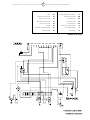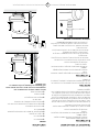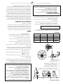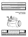
1
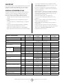
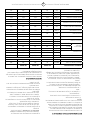
Operating Instructions and Owner’s Manual INSTRUCTIONS CAREFULLY: Read heatstar mr. heater READ and follow all instructions. Place instructions in BY eNERCO 2000ID a safe place for future reference. Do not allow anyone who has not read these instructions to assemble, light, adjust or operate the heater. Model Model 1000ID, 3000ID 1000ID, 2000ID 3000ID, 4000ID INDIRECT FIRED PORTABLE HEATER the information in this manual is not followed exactly, a fire or explosion WARNING: Ifmay result causing property damage, personal injury or loss of life. — Do not store or use gasoline or other flammable vapors and liquids in the vicinity of this or any other appliance. — Service must be performed by a qualified service agency. This is a vented portable heater. It uses air (oxygen) from the area in which it is used. Adequate combustion air and ventilation must be provided. Refer to page 5. ENERCO GROUP, INC., 4560 W. 160TH ST., CLEVELAND, OHIO 44135 • 800-251-0001 08/08 #50120 WARNING: WARNING: YOUR SAFETY IS IMPORTANT TO YOU AND TO OTHERS, SO PLEASE READ THESE INSTRUCTIONS BEFORE YOU OPERATE THIS HEATER. NOT FOR HOME OR RECREATIONAL VEHICLE USE WARNING: GENERAL HAZARD WARNING: FIRE, BURN, INHALATION, AND EXPLOSION HAZARD. KEEP SOLID COMBUSTIBLES, SUCH AS BUILDING MATERIALS, PAPER OR CARDBOARD, A SAFE DISTANCE AWAY FROM THE HEATER AS RECOMMENDED BY THE INSTRUCTIONS NEVER USE THE HEATER IN SPACES WHICH DO OR MAY CONTAIN VOLATILE OR AIRBORNE COMBUSTIBLES, OR PRODUCTS SUCH AS GASOLINE, SOLVENTS, PAINT THINNER, DUST PARTICLES OR UNKNOWN CHEMICALS. FAILURE TO COMPLY WITH THE PRECAUTIONS AND INSTRUCTIONS PROVIDED WITH THIS HEATER, CAN RESULT IN DEATH, SERIOUS BODILY INJURY AND PROPERTY LOSS OR DAMAGE FROM HAZARDS OF FIRE, EXPLOSION, BURN, ASPHYXIATION, CARBON MONOXIDE POISONING, AND/OR ELECTRICAL SHOCK. ONLY PERSONS WHO CAN UNDERSTAND AND FOLLOW THE INSTRUCTIONS SHOULD USE OR SERVICE THIS HEATER. IF YOU NEED ASSISTANCE OR HEATER INFORMATION SUCH AS AN INSTRUCTIONS MANUAL, LABELS, ETC. CONTACT THE MANUFACTURER. WARNING: The State of California requires the following warning: COMBUSTION BY-PRODUCTS PRODUCED WHEN USING THIS PRODUCT CONTAIN CARBON MONOXIDE, A CHEMICAL KNOWN TO THE STATE OF CALIFORNIA TO CAUSE CANCER AND BIRTH DEFECTS (OR OTHER REPRODUCTIVE HARM). Contents WARNING: WARNINGS................................................................................... 2 READ THE INSTRUCTIONS GIVEN IN THIS MANUAL BEFORE USING THE APPLIANCE. SPECIFICATIONS............................................................................ 3 • DO NOT USE GASOLINE, NAPHTHA OR VOLATILE FUELS. Safety devices........................................................................... 4 operation.................................................................................. 4 MAINTENANCE............................................................................. 5 • THE ELECTRICAL SYSTEM TO WHICH THE APPLIANCE IS CONNECTED MUST COMPLY WITH ALL SAFETY REGULATIONS IN FORCE. A RESIDUAL CURRENT CIRCUIT BREAKER MUST BE PROVIDED ON THE MAIN DISTRIBUTION BOARD. ventilation................................................................................ 5 TROUBLESHOOTING..................................................................... 6 wiring diagrams...................................................................... 7 parts list...................................................................................11 • UNPLUG THE HEATER BEFORE ATTEMPTING ANY SERVICE OR MAINTENANCE. • ALWAYS CHECK THE POWER SUPPLY CABLE BEFORE USE. IT MUST NOT BE BENT, CRUSHED, OR ANYWAY DAMAGED. • THE POWER SUPPLY CABLE MUST BE REPLACED ONLY BY QUALIFIED PERSONNEL. • ONLY USE AN ORIGINAL H07RN-F POWER CABLE WITH WATERPROOF PLUG. • DO NOT TOUCH THE EXHAUST GAS OUTLET. DANGER OF BURNS! ENERCO GROUP, INC. |Indirect Fired Portable Heater 2 Operating Instructions and Owner’s Manual Important to the heater requirements. Direct combustion heaters should only be used in well vented areas in order to avoid carbon monoxide poisoning. • The heater is installed near a chimney to take away the fumes (see “Ventilation” on page 5) and connected to an electrical switchboard. • When the heater is connected to a flue pipe, the flue pipe shall terminate in a vertical section at least two feet long and sufficient draft shall be created to assure safe and proper operation of the heater. • Never block air inlet (rear) or air outlet (front). • In case of very low temperatures add kerosene to the heating oil. • Make sure heater is always under surveillance and keep children and animals away from it; • Before starting the heater always check free rotation of ventilator fan. • Indirect fired units only can be connected to air ducts to distribute warm air, with respect to the max. static pressure declared (see “TECHNICAL SPECIFICATION” sheet). • Unplug heater when not in use. Before using the heater, read and understand all instructions and follow them carefully. The manufacturer is not responsible for damages to goods or persons due to improper use of units. General Recommendations This indirect-fired heater runs on diesel fuel. Those with direct combustion send hot air and the combustion products into the room, while those with indirect combustion are fitted with a flue to take the fumes away through the chimney. Always follow local ordinances and codes when using this heater: • Read and follow this owner’s manual before using the heater. • Use only in places free of flammable vapors or high dust content. • Never use heater in immediate proximity of flammable materials (the minimum distance must be 6 ft.). • Make sure fire fighting equipment is readily available. • Make sure sufficient fresh outside air is provided according mh 1000id hs 1000id mh 2000id hs 2000id mh 3000id hs 3000id hs 4000id [kBTU/h] 110 205 300 400 [cfm] 880 1,530 2,500 2,760 [kBTU/h] 91.9 174.9 254.4 335.6 [gal/h] 0.80 1.48 2.28 2.82 [lb/h] 5.53 10.35 15.07 20.07 1 1 1 1 TECHNICAL SPECIFICATIONS Heat input Air flow Fuel Type Diesel/Kerosene/#1-2 Fuel Oil Heat output Fuel consumption Phase Power supply Voltage [V] 120 120 120 120 Frequency [Hz] 60 60 60 60 [W] 520 785 1.240 1.440 [A] 5.76 8.30 11.40 13.20 [USgal/h] 0.60-80° S 1.00-45° W 1.20-45° W 1.50-45° W P1: 137 P1: 160 P1: 203 P2: 239 P2: 350 P2: 348 Electric consumption Nozzle Pump pressure Max static pressure Recommended max. temp. in the air duct Adjustment of combustion air flap Flue diameter [psi] 167 [in WC] 0.5 0.5 0.5 0.5 [°F] 250 250 250 250 [in] a=0.32 - - - N° - A=1.02 A=1.50 B=1.14 [in] 5.9 5.9 5.9 5.9 [in WC] 0.05 0.05 0.05 0.05 Tank capacity [gal] 10.8 17.2 27.7 35.7 Dimensions, L x W x H [in] 49.3x20.0x30.5 56.5x23.2x37.60 68.5x27.6x37.7 66.3x27.6x45.6 Net Weight [lb] 94 176 264 330 Compulsory flue draft ENERCO GROUP, INC. |Indirect Fired Portable Heater 3 Operating Instructions and Owner’s Manual Operation • The air inlet and outlet must never be blocked for any reason. • Install the heater on a flat, level floor in a steady postion. • It is forbidden to connect direct-fired heaters to air ducts. Before any attempt of starting the heater is made, check that your electrical supply conforms to the data on the model plate. Warning Control Board 1 3 4 2 • DO NOT USE GASOLINE, NAPHTHA OR VOLATILE FUELS. • STOP HEATER BEFORE ADDING FUELS. • ALWAYS FILL OUTDOORS AWAY FROM OPEN FLAME • DO NOT USE EXTERNAL FUEL SOURCE. • DO NOT OPERATE HEATER WHERE FLAMMABLE LIQUIDS OR VAPORS MAY BE PRESENT. • DO NOT START HEATER WHEN CHAMBER IS HOT • DO NOT START HEATER WHEN EXCESS FUEL HAS ACCUMULATED IN THE CHAMBER. • DO NOT PLACE COOKING UTENSILS ON TOP OF THE HEATER. • PLUG ELECTRICAL CORD INTO A PROPERLY GROUNDED THREE-PRONG RECEPTACLE. 5 ON 0 ON 1 RESET BUTTON WITH CONTROL LAMP 2 CONTROL LAMP 3 MAIN SWITCH 4 ROOM THERMOSTAT PLUG 5 POWER CORD The heater can only work automatically when a control device, such as for example a thermostat or a timer, is connected to the heater. Connection to the heater is made by removing the socket cover(4) and inserting the thermostat plug. To start the machine you must: •If connected to the thermostat, turn the switch to (ON + ); •If not connected to the thermostat, turn the switch to (ON). When unit is started for the first time or is started after the oil tank has been totally emptied, the flow of oil to the burner may be impaired by air in the circuit. In this case the control box will cut out the heater and it might be necessary to renew the starting procedure once or twice by depressing the reset button (1). Gap of Electrodes Should the heater not start, check that oil tank is full and depress reset button (1). X Should the heater still not work, please refer to chapter “OBSERVED FAULTS, CAUSES AND REMEDIES”. Y Stopping the Heater Z Set main switch (3) on “0” position or turn thermostat or other control device on lowest setting. The flame goes out and the fan continues to work for approx. 90sec. cooling the combustion chamber. Safety Devices Models X Y Z ID1000 .079 in .118 in .256 in ID2000 .158 in .098 in .158 in ID3000 .158 in .098 in .158 in ID4000 .158 in .098 in .158 in The unit is fitted with an electronic flame control box. In case of malfunction this box will cut in and stop the heater, at the same time the pilot lamp in the control box reset button (1) will light up. Heaters are also equipped with an overheat thermostat safety cutout which will stop the heater in case of overheating. This thermostat will reset automatically but you will have to depress button (1) on control box before being able to restart the heater. Clearances Transport The following minimum safety clearances from materials or objects in the surroundings of the heater must be ensured: Sides Top 2.5 ft. 6 ft. Warning Air Inlet 2.5 ft. Air outlet 12 ft. • Before making any attempt to restart heater find and eliminate reason of overheating. Before heater is moved it must be stopped and unplugged. Before moving the heater wait till it has totally cooled off and make sure oil tank cap is securely fixed. • Floors and ceilings must be made of fireproof materials in the room where the heater is operated. ENERCO GROUP, INC. |Indirect Fired Portable Heater 4 Operating Instructions and Owner’s Manual Description The hot air heaters with wheels must be wheeled. The suspended version which has no wheels must be transported with adequate machinery. A) Minimal 39” B) Minimal 39” Maintenance C) The shortest Preventive and regular maintenance will ensure a long trouble free life to your heater. D) The same or bigger than the smokes outlet diameter of heater E) Minimal 1m Warning 1) Anti-wind device provided with the heater • Never service heater while it is plugged in, operating or hot. Severe burns or electrical shock can occur. 2) Horizontal crossing with minimal upside angle pitch of 5° Every 50 hours of operation: disassemble filter and wash with clean oil, remove upper body parts and clean inside and ventilator with compressed air, check correct attachment of H.T. connectors to the electrodes and check H.T. cables, remove burner assembly, clean and check electrode settings, adjust according to scheme “GAP OF ELECTRODES”. 3) Chimney 8” x 8” of minimal inside measure 4) Chimney anti-explosion flap door 5) External seating wall 6) Chimney ending H shape N.B. Above recommendation indicative only. Have your installation checked by local authority. Flue Connections Diagram Ventilation C 6“ D 2 B 3 A 1 5 4 6 E C D 2 B A 5 ENERCO GROUP, INC. |Indirect Fired Portable Heater 5 Operating Instructions and Owner’s Manual 1 Troubleshooting TROUBLE Cause SOLUTION Motor does not start, no ignition No electrical current Check mains (should be 120 V – 1~ – 60 Hz) Check proper positioning and functioning of switch Check fuse Motor starts, no ignition or cuts out Wrong setting of room thermostat or other control Check correct setting of heater control. If thermostat, make sure selected temperature is higher than room temperature Thermostat or other control defective Replace control device Electrical motor defective Replace electrical motor Electrical motor bearings defective Replace electrical motor bearings Burned out condenser Replace condenser Electric ignitor defective Check connection of H.V. Ieads to electrodes and transformer Check electrodes setting (see scheme “GAP OF ELECTRODES”) Check electrodes for cleanliness Replace H.V. transformer Flame control box defective Replace control box Photocell defective Clean or replace photocell Not enough or no fuel at all at burner Check state of motor-pump plastic coupling Check fuel line system including fuel filter for possible leaks Clean or replace oil nozzle Solenoid defective Check electrical connection Check thermostat LI Clean or replace solenoid Motor starts, heater emits smoke Not enough combustion air Make sure air inlet and outlet are free Check setting of combustion air flap Clean burner disc Too much combustion air Check setting of combustion air flap Fuel contaminated or contains water Drain fuel in tank with clean fuel Air leaks in fuel circuit Check the seals on the ducts and the diesel filter Not enough fuel at burner Check pump pressure Clean oil filter Clean or replace fuel nozzle Too much fuel at burner Check pump pressure Replace nozzle Heater does not stop Solenoid Replace solenoid coil or complete solenoid If heater still not working properly, please revert to nearest authorized dealer. ENERCO GROUP, INC. |Indirect Fired Portable Heater 6 Operating Instructions and Owner’s Manual Wiring Diagram 1000ID Series Models Drawing Legend FU Fuse RV Control IT Transformer H.V. TA Room Thermostat LI1 Overheat Thermostat RE Relays EV1 Solenoid Valve 1° AP Control Box FO Photocell PA Air pressure control CO Condenser RF Heater filter MV Fan Motor FA Fan thermostat ST Electric pilot PE Ground ENERCO GROUP, INC. |Indirect Fired Portable Heater 7 Operating Instructions and Owner’s Manual Wiring Diagram 2000ID and 3000ID Series Models Drawing Legend FU Fuse 20A RV Control IT Transformer H.V. TA Room Thermostat plug LI1Overheat Thermostat RE Relay EV1 Solenoid Valve 1° AP Control Box EV2 Solenoid Valve 2° FA Fan thermostat FO Photocell PA Air pressure control CO Condenser RF Heated filter MV Fan Motor PA Air pressure switch STElectric pilot lamp PE Ground ENERCO GROUP, INC. |Indirect Fired Portable Heater 8 Operating Instructions and Owner’s Manual Wiring Diagram 4000ID Series Models Drawing Legend FU Fuse 20A TA Room Thermostat plug IT Transformer H.V. RE Relay LI1Overheat Thermostat AP Control Box EV1 Solenoid Valve 1° FA Fan thermostat EV2 Solenoid Valve 2° RF Heated filter FO Photocell CN Connector CO Condenser MV Fan Motor LI2Overheat safety thermostat STElectric pilot lamp RV PE Ground Control ENERCO GROUP, INC. |Indirect Fired Portable Heater 9 Operating Instructions and Owner’s Manual 1000ID Series Indirect-Fired Portable Heater B 62 35 51 52 63 72 49 64 50 53 54 55 71 48 81 65 70 03 47 01 46 66 45 68 56 57 44 67 69 43 58 59 04 02 37 61 60 36 39 35 34 32 42 06 33 30 41 40 38 31 82 B A 05 29 28 81 08 80 07 83 23 26 14 87 18 24 25 09 27 15 88 89 19 22 86 21 17 A 73 15 18 74 76 20 11 Optional 16 78 77 10 75 15 84 85 12 68 13 77 Operating Instructions and Owner’s Manual 10 ENERCO GROUP, INC. |Indirect Fired Portable Heater 1000ID Series Indirect-Fired Portable Heater Parts List no. 01 02 03 04 05 06 07 08 09 10 11 12 13 14 15 16 17 18 19 20 21 22 23 24 25 26 27 28 29 30 31 32 33 34 35 36 37 38 39 40 41 42 43 44 45 Stock No. Description g06075-9010 g06077 g06079 g06081 g06083-9010 g06085-9010 e10677-110 e11208 g06067 g06070-9010 t10207 m20402 p30165 i40330 i20104 t20239 g06104-9005 i40329 c30307 p20174-9005 c30319 p20175-9005 i40331 i30695 i30737 g06068-9005 g06099-9005 c30356 g06105-9005 g06106-9005 c10546 m20202 i25019 c30350 g00212 c30425 p50127 g06108-9010 e50101 g06087 e50102 g06072 p50126 e20508 e10308 Outlet cone Chimney Ø 150 Combustion chamber support Combustion chamber Upper body Lower body Motor 200Wwith condenser Condenser 20 µF Motor flange Fan protection ring Fan Ø300 18° Elastic Plate U42-032 Inlet grille Tube BP 1/4” FF L.420mm Nipple FE 1/4” MM Filter with cartridge Filter support Tube BP 1/4”FF L.260mm Protection cable Ø 35 Handle Plug Ø25 Foot Tube BP 1/4” F L.580mm Pascante L.150mm Nipple OT 1/4” M - M12x1.75M Power lead hook Fuel tank Drain plug Wheel axle Wheels axle support Wheel Ø 260 - Ø 25 Spring washer Ø20 Fuel tank OR Ø30 x 2.62 El. Components drawer Seal Control box cover Base Limit thermostat Blast tube Fan thermostat Sleeve Ø8 x Ø6 x 9.5 Electr. Components drawer Fuse holder Fuse (6x30) 10A ENERCO GROUP, INC. |Indirect Fired Portable Heater No. 46 47 48 49 50 51 52 53 54 55 56 57 58 59 60 61 62 63 64 65 66 67 68 69 70 71 72 73 74 75 76 77 78 79 80 81 82 83 84 85 86 87 88 89 11 Stock no. g06102 e50437 e20319 e20305 e11125 e10917-2 g06109 g06103 e40107 e40113 g06073 e10102-p e20640 e20665 e30443 e11030 t20339 i33001 p20526 i31034 e10248 g02076 i40192 e50306 e50307 e50308 c30352 t20429-1 t20118 t20117 i20115 e10513 e20953 e20954 i20325 i31130 i40332 c30319 t20241 t20242 t20201 t20234 t20206 t20212 Description Switch support Pressure switches HONEYWELL Terminal board Terminal board Relay finder 65.31 AC Transformer H.T. 818C 110V Transformer H.T. flange Support LANDIS LOA 21-24 base Control box LANDIS LOA 21-24 Plate for electrical components Switch 0 - 1 Thermostat plug 3P+T Drain plug El. wire with plug and cable fastener Lamp 230V Nozzle 0.60 GPH 80° S Nozzle support Burner flange Ø 80mm Nut M14 Electrode H.T. Cable connect 90° Micro pipe Ld. ph. UnitL&G QRB1A Fixing clamp Photo resistance flange Cable protection Ø15 Pump Danfoss BFP01 Solenoid spool BFP11-21 Danfoss Solenoid valve Danfoss Nipple FE 1/8” MM Coupling K1 Cable holder PG11 Ring nut PG11 Connection1/8” Conn. Straight Ø6 1/8” Silicone pipe Ø5x9 Rubber tap OR KIT oil filter Filter cartridge Oil filter 1/4” OR KIT oil filter Filter cartridge Filter housing Operating Instructions and Owner’s Manual 2000ID/3000ID Series Indirect-Fired Portable Heaters B 71 33 60 61 72 59 57 38 75 03 74 73 58 62 63 64 01 76 56 55 65 04 77 46 45 69 70 79 78 80 52 67 68 53 81 54 82 66 02 35 34 47 07 32 33 30 49 31 29 48 50 36 38 28 B 51 27 05 37 38 26 A 37 40 44 42 25 24 21 43 41 38 08 09 39 19 06 17 22 23 10 20 13 A 83 14 11 19 15 84 85 14 15 16 17 12 86 87 89 90 18 14 79 88 Operating Instructions and Owner’s Manual 12 ENERCO GROUP, INC. |Indirect Fired Portable Heater 2000ID/3000ID Series Indirect-Fired Portable Heater Parts List no. Stock No. 2000 01 G06113-9010 • G06114-9010 G06077 • 03 G06115 • G06116 G06117 G06119-9010 G06121-9010 G06123-9010 • E10678-110 E11230 G06125-9010 T10260 P30169 E20953 • • Cable holder PG11 Chimney Ø 150 43 E20954 • • Ring nut PG11 Combustion chamber support 44 C30307 • • Protection cable 035 45 E50102 • • Limit Thermostat Combustion chamber 46 M20107 • • Washer Ø5 x Ø15 x 1.5 47 E50101 • • • • • • • Fan Thermostat G06132 • • 49 G06133 • • 50 I40801 • 51 G06134 Motor 450W with condenser 52 Motor 750W with condenser 53 Condenser 40µF I40802 Blast tube Clip for flexible ducts Doppelmaterial-Schlauch L=170 mm • Doppelmaterial-Schlauch L=170 mm • • Air flap P50126 • • Electr. Components drawer E20508 • • Fuse holder 54 E10313 • • Fuse (6x30) 20A Condenser 40µF 55 G06102 • • SVvitch support Motor flange 56 E50437 • • Pressure switches HONEYWELL 57 E20319 • • Terminal board Fan Ø356 18° 58 E11125 • • Relay Finder 65.31 AC Fan Ø500 23° 59 E20305 • • Terminal board Inlet grille 60 E10917-2 • • Transfonner H.V. 818C 110V • • Description • 48 Lower body • Stock No. E50104 • T10261 12 Conn. Straight Ø6 1/8” 42 Cover inspection • G06126-9010 11 • • E11229 10 • • E10679-110 09 3000 I31130 Upper body • G06124-9010 08 2000 41 • G06122-9010 07 no. Outlet cone • G06120-9010 06 • • G06118 05 Description • 02 04 3000 61 G06109 • • Transfonner H.V. Flange 13 I40330 • • TuBe BP 1/4” FF L.420mm 62 G06103 • • Support 14 I20104 • • Nipplo FE 1/4” MM 63 E40107 • • LANDIS LOA 21-24 base 15 T20239 • • Oil pre-heaters filter 1/4” 64 E40113 • • Control box LANDIS LOA 21-24 16 G06104-9005 • • Filter support 65 G06073 • • Plate for electrical components 17 I40329 • • Tube BP 1/4” FF L.260mm 66 E10102-P • • Switch 0 -1 P20174-9005 • P30129 18 • P20176-9005 67 E20640 • • Thermostat plug 3P+T 68 E20665 • • Drain plug Plug Ø25 69 E30443 • • EI. wire with plug and cable fastener Foot 70 E11030 • • Lamp 230V 71 T20354 • Handle • 19 C30319 • 20 P20175-9005 • 21 I40331 • • Tube BP 1/4” F L.580mm 22 I30696 • • Pascante L.220mm 23 I30737 • • Nipplo OT 1/4” M - M12x1.75M 24 G06068-9005 • • Power lead hook 73 E10254 25 G06127-9005 • • Fuel tank 65 l 74 G06128-9005 • • Fuel tank 105 l 26 C30367 • • 27 G06105-9005 • P20177-9005 • • T20351 72 P10137 Nozzle 1,00 GPH 45° W • • P10138 Nozzle 1,20 GPH 45° W Burner’s head with electrodes • Burner’s head with electrodes • • Electrodes P10134 • • Electrodes stirrup 75 I33002 • • Nozzle support Drain plug 76 I30685 • • Washer diam. 14 Wheel axle 77 P20529 • • Burner flange 0 102mm • Wheels axle support 78 G02076 • • H.T. Cable connect. 90° 28 G06106-9005 • • Wheel Ø 260 - Ø 25 79 I40192 • • Micropipe 29 C10546 • • Spring washer Ø 25 80 E50306 • • Ld ph. Unit L&G QRB1A 30 M20202 • • Fuel tank 81 E50307 • • Fixing clamp 31 I25019 • • OR Ø30 x 2.62 82 E50308 • • Photoresistance flange 32 C30350 • • El. components drawer 83 T20439-1 • 33 G00213 • • Seal 34 C30425 • • Control box cover 84 T20118 • • Solenoid spool BFP 52E Danfoss 35 P50127 • • Base 85 T20129 • • Solenoid valve Danfoss (NO) G06130-9010 • 86 T20117 • • Solenoid valve Danfoss (NC) • Conn. Straight Ø6 1/8” 87 I20115 • • Nipplo FE 118” MM 88 E10513 • G06129-9005 36 G06131-9010 T20440-1 37 I31130 • • Silicone pipe Ø5x9 38 I40332 • • Connection 1/8” 39 I30325-1 • • Connection 1/8” 89 T20241 40 I20325 • • Connection 1/8” 90 T20242 ENERCO GROUP, INC. |Indirect Fired Portable Heater E10514 13 Pump Danfoss BFP 52E R3 • Pump Danfoss BFP 52E R5 Coupling K1 • Coupling K2 • • OR KIToil filter • • Filter cartridge Operating Instructions and Owner’s Manual 4000ID Series Indirect-Fired Portable Heaters 02 01 03 40 04 39 38 33 32 34 05 31 29 06 42 36 30 41 35 37 28 43 47 44 45 46 48 A 07 25 03 18 22 24 26 17 27 17 11 21 23 24 10 09 15 18 08 20 B 12 13 19 14 15 16 ENERCO GROUP, INC. |Indirect Fired Portable Heater 14 Operating Instructions and Owner’s Manual 4000ID Series Indirect-Fired Portable Heaters 38 58 59 57 56 60 61 62 21 86 55 54 53 97 52 63 64 94 86 51 50 65 48 21 C 93 66 49 22 92 68 67 54 98 A 47 69 46 45 91 87 90 71 72 73 70 88 89 74 79 78 76 75 77 C 80 94 82 81 96 95 83 84 86 76 85 ENERCO GROUP, INC. |Indirect Fired Portable Heater 15 Operating Instructions and Owner’s Manual 4000ID Series Indirect-Fired Portable Heater Parts List No. Stock No. Description No. Stock No. Description 01 G06156-9010 Outlet cone 34 G06165-9005 Fuel tank 135 I 02 G06157 Centrifuge air fan 35 C30367 Drain plug 03 E50767 Thermostat TY95A 105°C Campini 36 G06068-9005 Power lead hook 04 G06171 Combustion chamber support 37 G06166-9010 Base 05 G06158 Combustion chamber 38 G00214 EI. componets drawer 06 G06077 Chimney 0 150 39 C30425 Seal 07 G06159-9010 Upper body 40 P50127 Control box cover 08 G06160-9010 Cover inspection 41 E50102 Limit Thermostat 09 G06161-9010 Lower body 42 M20107 Washer 05 x 015 x 1,5 10 E10679-110 Motor 750W with condenser 43 E50104 Fan Thermostat 11 E11229 Condenser 80 µF 44 G06167 Blast tube 12 G06172-9010 Motor flange 45 M20408 Nut M5 13 T10261 Fan 0500 23° 46 G06133 Clip for flexible ducts 14 P30129 Inlet grille 47 M10244 Screw TCEI M5x14 15 C30328 Plug 030 48 140803 Air duct L=600 mm 16 P20182-9005 Handle 49 G06153 Electr. componets drawer 17 G06162-9010 Washer for Air duct 50 E20508 Fuse holder 18 C30307 Protection cable 0 35 51 E10313 Fuse (6x30) 20A 19 P50133 Crankcase 52 G06102 Switch support 20 P20181-9005 Wheels frame 53 E50437 Pressure switchesHONEYWELL 21 140333 Tube BP 1/4” FF L.200mm 54 140332 Silicone pipe 05x9 22 140330 Tube BP 1/4” FF L.420mm 55 E20319 Terminal board 23 130696 Pascante L.290mm 56 E11125 Relay Finder 65.31 AC 24 130737 Nipplo OT 1/4” M - M12x1,75 M 57 E20305 Terminal board 25 G06163-9005 Stirrup 58 E10917-2 Transformer H.T. 818C 110V 26 G06164-9005 Wheels support 59 G06109 Transformer H.T. flange 27 C10547 Pivotal wheel 60 G06103 Support 28 G06129-9005 Wheel axle 61 E40107 LANDIS LOA 21-24 base 29 G06151-9005 Wheels axle support 62 E40113 Control box LANDIS LOA 21-24 30 C10546 Wheel 0 260 - 0 25 63 G06073 Plate for electrical components 31 M20202 Spring washer 025 64 E10102-P Switch 0-1 32 125019 Drain plug 65 E20640 Thermostat plug 3P+T 33 C30350 OR 030 x 2,62 66 E20665 Drain plug ENERCO GROUP, INC. |Indirect Fired Portable Heater 16 Operating Instructions and Owner’s Manual 4000ID Series Indirect-Fired Portable Heater Parts List No. Stock No. Description 67 E30443 EI. wire with plug and cable fastener 68 E11030 Lamp 230V 69 T20353 Nozzle 1,50 GPH 45° W 70 P10137 Burner’s head with electrodes 71 E10254 Electrodes 72 P10134 Electrodes stirrup 73 133002 Nozzle support 74 P20529 Burner flange 0 102mm 75 G02076 H.T. Cable connect. 90° 76 140193 Micropipe L=800 mm 77 E50306 Ld ph. Unit L&G QRB1A 78 E50307 Fixing clamp 79 E50308 Photoresistance flange 80 T20439-1 Pump Danfoss BFP 52E R3 81 T20118 Solenoid spool BFP 52E Danfoss 82 T20129 Solenoid valve Danfoss (NO) 83 T20117 Solenoid valve Danfoss (NC) 84 120115 Nipplo FE 1/8” MM 85 E10513 Coupling K1 86 120104 Nipplo FE 1/4” MM 87 C10328 Leitungskanal 88 C10326 Spiral fan 89 G06168 Shutter for air regulation 90 T10262 Fan AP 160x55 F12,7 91 G06169-9005 Support fan and motor 92 E10677-110 Motor 200W with condenser 93 E11233 Condenser 20 IJF 94 T20239 Oil pre-heaters filter 1/4” 95 T20241 OR KIToil filter 96 T20242 Filter cartridge 97 G06170-9005 Filter support 98 131121 Conn. Straight 04,5 M5 Column intentionally left blank ENERCO GROUP, INC. |Indirect Fired Portable Heater 17 Operating Instructions and Owner’s Manual Operating Instructions and Owner’s Manual READ INSTRUCTIONS CAREFULLY: Read heatstar mr. Heater and follow all instructions. Place instructions in BY eNERCO 2000ID a safe place for future reference. Do not allow anyone who has not read these instructions to assemble, light, adjust or operate the heater. Model Model 1000ID, 3000ID 1000ID, 2000ID 3000ID, 4000ID WARNING: USE ONLY MANUFACTURER’S REPLACEMENT PARTS. USE OF ANY OTHER PARTS COULD CAUSE INJURY OR DEATH. REPLACEMENT PARTS ARE ONLY AVAILABLE DIRECT FROM THE FACTORY AND MUST BE INSTALLED BY A QUALIFIED SERVICE AGENCY. PARTS ORDERING INFORMATION: PURCHASING: Accessories may be purchased at any Mr. Heater/HeatStar local dealer or direct from the factory FOR INFORMATION REGARDING SERVICE Please call Toll-Free 800-251-0001 • www.enerco-mrheater.com Our office hours are 8:30 AM – 5:00 PM, EST, Monday through Friday. Email to: [email protected] Please include the model number, date of purchase, and description of problem in all communication. LIMITED WARRANTY The company warrants this product to be free from imperfections in material or workmanship, under normal and proper use in accordance with instructions of The Company, for a period of one year from the date of delivery to the buyer. The Company, at its option, will repair or replace products returned by the buyer to the factory, transportation prepaid within said one year period and found by the Company to have imperfections in material or workmanship. If a part is damaged or missing, call our Technical Support Department at 800-251-0001. Address any Warranty Claims to the Service Department, Enerco Group, Inc., 4560 W. 160TH ST., Cleveland, Ohio 44135. Include your name, address and telephone number and include details concerning the claim. Also, supply us with the purchase date and the name and address of the dealer from whom you purchased our product. The foregoing is the full extent of the responsibility of the Company. There are no other warranties, express or implied. Specifically there is no warranty of fitness for a particular purpose and there is no warranty of merchantability. In no event shall the Company be liable for delay caused by imperfections, for consequential damages, or for any charges of the expense of any nature incurred without its written consent. The cost of repair or replacement shall be the exclusive remedy for any breach of warranty. There is no warranty against infringement of the like and no implied warranty arising from course of dealing or usage of trade. This warranty will not apply to any product which has been repaired or altered outside of the factory in any respect which in our judgment affects its condition or operation. Some states do not allow the exclusion or limitation of incidental or consequential damages, so the above limitation or exclusion may not apply to you. This Warranty gives you specific legal rights, and you may have other rights which vary from state to state. Enerco Group, Inc. reserves the right to make changes at any time, without notice or obligation, in colors, specifications, accessories, materials and models. ENERCO GROUP, INC., 4560 W. 160TH ST., CLEVELAND, OHIO 44135 • 800-251-0001 Mr. Heater is a registered trademark of Enerco Group, Inc. © 2004, ENERCO GROUP, INC. All rights reserved ENERCO GROUP, INC. |Indirect Fired Portable Heater 18 Operating Instructions and Owner’s Manual 08/08 #50120 Guide d’utilisation et instructions de fonctionnement MR. HEATER Modèle 2000ID LISEZ SOIGNEUSEMENT LES INSTRUCTIONS : Lisez et observez toutes les instructions. Conservez les instructions pour vous y référer ultérieurement. Interdisez à quiconque n’ayant pas lu les présentes instructions d’assembler, d’allumer, de régler ou de faire fonctionner cet appareil de chauffage. Modèle 1000ID, 3000ID heatstar BY eNERCO 1000ID, 2000ID 3000ID, 4000ID AVERTISSEMENT: N’UTILISEZ QUE LES PIÈCES DE REMPLACEMENT DU FABRICANT. IL EST POSSIBLE DE SE PROCURER CES PIÈCES DIRECTEMENT DE L’USINE OU PAR L’ENTREMISE DES DÉTAILLANTS LOCAUX MR. HEATER/HEATSTAR. INFORMATIONS SUR LA COMMANDE DE PIÈCES : ACHAT : On peut se procurer les accessoires par l’entremise de tous les détaillants locaux Mr. Heater/HeatStar ou directement du fabricant POUR OBTENIR DES INFORMATIONS SUR LE SERVICE Appelez sans frais au 800-251-0001 • www.enerco-mrheater.com Nos heures d’ouverture sont de 8 h 30 à 17 h HNE, du lundi au vendredi. Adressez vos courriels à : [email protected] Veuillez indiquer le numéro du modèle, la date d’achat et la description du problème dans toutes vos communications avec nous. GARANTIE LIMITÉE L’entreprise garantit ce produit contre tout défaut de matériel ou de main-d’œuvre, dans des conditions d’utilisation normale et adéquate, conformément aux instructions de l’entreprise, pour une période d’un an à compter de la date de livraison à l’acheteur. L’entreprise réparera ou remplacera, à sa discrétion, les produits retournés port payé par l’acheteur au fabricant dans la période d’un an et jugés par l’entreprise comme présentant des défauts de matériel ou de maind’œuvre. Si une pièce est endommagée ou manquante, téléphonez à notre service de soutien technique au 800-251-0001. Adressez toute réclamation relative à la garantie à Service Department, Enerco Group, Inc., 4560 W. 160TH ST., Cleveland, Ohio 44135 États-Unis. Indiquez vos nom, adresse et numéro de téléphone ainsi que les détails de la réclamation. Indiquez-nous également la date d’achat et le nom et l’adresse du détaillant de qui vous avez acheté le produit. Ce qui est énoncé ci-dessus constitue la responsabilité totale de l’entreprise. Il n’existe aucune autre garantie, expresse ou tacite. Plus précisément, il n’y a aucune garantie concernant l’adéquation à une utilisation particulière ni aucune garantie concernant la qualité marchande. En aucun cas l’entreprise ne sera tenue responsable des retards causés par des défectuosités, ni des dommages indirects, ni des dépenses encourues sans son consentement écrit, quelle que soit leur nature. Le coût de la réparation ou du remplacement sera le seul recours possible en cas de violation de garantie. Il n’y a aucune garantie contre une transgression de ce genre ni aucune garantie tacite découlant des usages du commerce ou de la façon habituelle d’échanger. La présente garantie ne s’applique à aucun produit qui a été réparé ou modifié par d’autres que le fabricant si cela influe de quelque façon que ce soit sur l’état de l’appareil ou son fonctionnement, selon notre jugement. Certains États ou provinces ne permettent pas d’exclure ou de limiter les dommages indirects ou subséquents. Par conséquent, les limitations ou exclusions ci-dessus mentionnées ne vous concernent peut-être pas. La présente garantie vous accorde des droits juridiques précis, mais vous pourriez avoir d’autres droits qui varient selon la province ou l’État. Enerco Group Inc. se réserve le droit d’effectuer des modifications en tout temps, sans préavis ni obligation, aux couleurs, aux spécifications, aux accessoires, aux matériaux et aux modèles. ENERCO GROUP, INC., 4560 W. 160TH ST., CLEVELAND, OHIO 44135 É.-U. • 800-251-0001 Mr. Heater et HeatStar sont des marques de commerce déposées de Enerco Group, Inc. © 2003, Enerco Group Inc. Tous droits réservés. ENERCO GROUP, INC., 4560 W. 160TH ST., CLEVELAND, OHIO 44135 • 800-251-0001 08/08 #50120 4000ID Série Chauffage Portatif Indirect-tiré No. Stock No. Description 131121 98 G06170-9005 97 T20242 96 T20241 95 Filtre pre-chauffage 1/4" T20239 94 Condensateur 20 IJF E11233 93 E10677-110 92 G06169-9005 91 T10262 90 G06168 89 C10326 88 C10328 87 Nipplo FE 1/4" MM 120104 86 Accouplememt PI. K1 E10513 85 120115 84 T20117 83 T20129 82 T20118 81 T20439-1 80 E50308 79 E50307 78 E50306 77 140193 76 G02076 75 P20529 74 133002 73 P10134 72 E10254 71 P10137 70 T20353 69 E11030 68 E30443 67 Cable avec fiche et presse cable Lampe 230V Gicleur 1,50 GPH 45° W Tete brOleur avec electrodes Electrodes Etrier pour electrodes Support gicleur Bride BrOleur 0 102mm Conn. cable 90° H.T. Microtube L=800 mm Photoresis. L&G QRB1A Boucle de fixage Bride photoresistance Pompe Danfoss BFP 52E R3 Bobine EV BFP 52E Danfoss Electrovanne Danfoss (NO) Electrovanne Danfoss (NC) Nipplo FE 1/8" MM Canal du liaison Ecrou ventilateur Ciapet reglage air Ventilateur AP 160x55 F12,7 Support moteur et ventilateur Moteur 200W avec condensateur KIT OR filtre gasoil Cartouche filtre Support Raccord droit 04,5 M5 LA COLONNE A INTENTIONNELLEMENT QUITTÉ LE BLANC ENERCO GROUP, INC. |Chauffage portatif indirect-tiré 17 Le fait de Faire marcher des Instructions et le Manuel de Propriétaire 4000ID Série Chauffage Portatif Indirect-tiré No. Stock No. C30350 33 125019 32 M20202 31 C10546 30 G06151-9005 29 G06129-9005 28 C10547 27 G06164-9005 26 G06163-9005 25 130737 24 130696 23 140330 22 140333 21 P20181-9005 20 P50133 19 C30307 18 G06162-9010 17 P20182-9005 16 C30328 15 P30129 14 T10261 13 G06172-9010 12 E11229 11 E10679-110 10 G06161-9010 09 G06160-9010 08 G06159-9010 07 G06077 06 G06158 05 G06171 04 E50767 03 G06157 02 G06156-9010 01 Description Embout conique Ventilateur complet Thermostat TY95A 105°C Campini Protection chambre de combustion Chambre de combustion Cheminee 0 150 Carrosserie sup. Porte visite Carrosserie Inf. Moteur 750W avec condensateur Condensateur 80 IJF Bride support moteur Ventilateur 0500 23° Grille protection Bouchon 030 Poignee Rondelle pour gaine Prot. caoutchouc 0 35 Carter Chassis roues Tube BP 1/4" FF L.200mm Tube BP 1/4" FF L.420mm Pascante L.290mm Nipplo OT 1/4" M - M12x1,75 M No. Stock No. 34 35 36 37 38 39 40 41 42 43 44 45 46 47 48 49 50 51 52 53 54 55 56 57 59 Support roues 58 Etrier Roue pivotante 60 62 Support on essieu roues 61 Essieu Roue 0 260 - 0 25 Rondelle elastique 025 Bouchon de vidange OR 030 x 2,62 ENERCO GROUP, INC. |Chauffage portatif indirect-tiré 16 63 64 65 66 G06165-9005 C30367 G06068-9005 G06166-9010 G00214 C30425 P50127 E50102 M20107 E50104 G06167 M20408 G06133 M10244 140803 G06153 E20508 E10313 G06102 E50437 140332 E20319 E11125 Description Reservoir fuel 135 I Bouchon Crochet cable d'alimentation Base Coffret electrique Joint Couverture coffret electrique Thermostat bilame Limit Rondelle 05 x 015 x 1,5 Thermostat bilame Fan Gueulard Ecrou M5 Collier de fixation gaines Vis TCEI M5x14 Gaine L=600 mm Support coffret electrique Porte fusible Fusible (6x30) 20A Support pressostat Pressostats HONEYWELL Tuyau en silicone 05x9 Barrette de connection Relais Finder 65.31 AC Transformateur H.T. 818C 110V E10917-2 Barrette de connection E20305 G06109 G06103 E40107 E40113 G06073 E10102-P Support transformateur H.T. Support Support LANDIS LOA 21-24 Coffret LANDIS LOA 21-24 Plaqu support Interrupteur 0 - 1 Bouchon E20665 Fiche thermostat 3P+T E20640 Le fait de Faire marcher des Instructions et le Manuel de Propriétaire 4000ID Série Chauffage Portatif Indirect-tiré 38 59 58 21 56 60 61 62 57 86 54 55 97 53 94 64 86 63 52 48 65 50 21 C 51 22 93 92 66 49 67 54 68 98 47 A 91 46 45 69 90 87 71 72 88 73 70 89 79 74 78 77 C 76 75 80 82 81 94 86 83 84 96 95 85 76 15 ENERCO GROUP, INC. |Chauffage portatif indirect-tiré Le fait de Faire marcher des Instructions et le Manuel de Propriétaire 4000ID Série Chauffage Portatif Indirect-tiré 02 04 39 03 40 01 38 33 31 32 34 05 30 36 42 29 06 37 28 35 41 43 47 46 45 48 44 A 25 07 24 22 26 18 03 27 17 17 24 23 21 11 09 10 15 18 08 20 B 12 19 13 14 15 16 14 ENERCO GROUP, INC. |Chauffage portatif indirect-tiré Le fait de Faire marcher des Instructions et le Manuel de Propriétaire 2000ID/3000ID Série Chauffage Portatif Indirect-tiré G06113-9010 01 Stock No. no. G06077 02 G06117 G06104-9005 16 T20239 15 I20104 14 I40330 13 I30737 23 I30696 22 I40331 21 2000 3000 • Cheminée Ø 150 porte visite • • • • • • moteur 750W avec condensateur condensateur 80µF ventilateur Ø500 23° TuBe BP 1/4” FF L.420mm Nipplo FE 1/4” MM filtre pre-chauffage 1/4” support Tube BP 1/4” FF L.260mm bouchon Ø25 pied • • • • • • • G06128-9005 G00213 33 • • C30350 32 • • I25019 31 M20202 30 C10546 29 G06106-9005 28 • • • • • • • • • • • • • support on essieu roues roue Ø 260 - Ø 25 rondelle élastique Ø 25 réservoir fuel OR Ø30 x 2.62 no. 41 Stock No. I31130 E20954 43 E20953 42 44 C30307 M20107 E50102 45 E50101 2000 G06132 70 84 85 88 89 90 G06134 P50126 E20508 E10313 G06102 E50437 E20319 E11125 E20305 E10917-2 G06109 G06103 E40107 E40113 G06073 E10102-P E20640 E20665 E30443 E11030 P10137 E10254 P10134 I33002 I30685 P20529 G02076 I40192 E50306 E50307 E50308 T20439-1 T20118 T20129 T20117 I20115 E10513 T20241 T20242 3000 legende raccord droit Ø6 1/8” • • • • • • • • • • • embout fixe-cable PG11 embout PG11 prot. caoutchouch Ø 35 thermostat bilame limit rondelle Ø5 x Ø15 x 1.5 thermostat bilame fan • E50104 G06133 49 48 I40801 • • • • • • • • • • • • • • • • • • • • • • • • • • • • • • • • • • • • • • • • • • • • • • • • gueulard gaine L=170 mm déflecteur d’air support coffret éléctrique porte fusible fusible (6x30) 20A support pressostat pressostats HONEYWELL barrette de connection relais Finder 65.31 AC barrette de connection transformateur H.V. 818C 110V support transformateur H.V. Support Support LANDIS LOA 21-24 base coffret LANDIS LOA 21-24 plaqu support interrupteur 0 -1 fiche thermostat 3P+T bouchon câble avec fiche et pressee câble Lampe 230V gicleur 1,00 GPH 45° W • gicleur 1,20 GPH 45° W tête brûleur avec éléctrodes • • • • • • • • • • • • • • • • • • • • • tête brûleur avec éléctrodes éléctrodes étrier pour éléctrodes support gicleur rondelle diam. 14 bride brûleur Ø 102mm conn. câble 90° H.V. Microtube photoresis. L&G QRB1A boucle de fixage bride Photoresistance pompe Danfoss BFP 52E R3 • • • • • • • • • • pompe Danfoss BFP 52E R5 bobine E.V. BFP 52E Danfoss electrovanne Danfoss (NO) electrovanne Danfoss (NC) Nipplo FE 118” MM accouplement K1 • • • • collier de fixation gaines gaine L=170 mm • I40802 52 53 54 55 56 58 59 60 62 63 64 65 66 67 69 72 73 74 75 76 77 79 80 81 82 83 T20440-1 coffret éléctrique joint couverture coffret éléctrique raccord droit Ø6 1/8” E10514 tuyau en silicone Ø5x9 coude 1/8” T20354 T20351 Tube BP 1/4” F L.580mm Pascante L.220mm P10138 Nipplo OT 1/4” M - M12x1.75M crochet câble d’alimentation réservoir fuel 65 l réservoir fuel 105 l bouchon essieu • C30425 34 • • • coude 1/8” • • • I20325 I20325 86 87 • • • 46 47 • carrosserie sup. • • • 50 • carrosserie inf. • 51 • moteur 450W avec condensateur • • condensateur 40µF • • bride support moteur • 57 • ventilateur Ø356 18° • • grille protection • 61 • • • • • • Poignée • 68 • • • 71 • • • • • • • • C30367 78 • P50127 35 I31130 37 base • G06131-9010 I40332 38 legende • • Protection chambre de combustion • • chambre de combustion • G06118 G06119-9010 G06121-9010 G06123-9010 E10678-110 E11230 G06125-9010 T10260 P30169 I40329 17 C30319 19 G06068-9005 24 embout conique • G06114-9010 G06115 03 G06116 04 05 G06120-9010 06 G06122-9010 07 G06124-9010 08 E10679-110 09 E11229 10 G06126-9010 11 T10261 12 P30129 P20174-9005 18 P20176-9005 P20175-9005 20 P20177-9005 G06127-9005 25 G06105-9005 27 26 G06129-9005 G06130-9010 36 I30325-1 39 40 • • accouplement K2 KIT or filtre gasoil cartouche filtre coude 1/8” ENERCO GROUP, INC. |Chauffage portatif indirect-tiré 13 Le fait de Faire marcher des Instructions et le Manuel de Propriétaire 61 60 33 71 B 72 58 62 63 64 59 74 73 57 38 75 03 01 56 76 66 65 55 52 80 45 69 70 79 78 46 67 68 53 81 54 82 77 04 35 02 34 32 07 33 30 47 31 49 29 50 28 38 36 48 51 27 B 38 37 26 05 A 37 19 39 40 25 24 44 42 21 43 41 38 08 09 06 23 22 17 10 20 13 83 A 19 11 15 84 85 14 16 12 17 2000ID/3000ID Série Chauffage Portatif Indirect-tiré 18 90 89 14 86 87 14 15 88 79 Le fait de Faire marcher des Instructions et le Manuel de Propriétaire 12 ENERCO GROUP, INC. |Chauffage portatif indirect-tiré 1000ID Série Chauffage Portatif Indirect-tiré Bouchon e20665 59 Fiche thermostat 3P+T e20640 58 Interrupteur 0 - e10102-p 57 g06073 56 Coffret LANDIS LOA 21-24 e40113 55 Support LANDIS LOA 21-24 e40107 54 g06103 53 g06109 52 e10917-2 51 e11125 50 e20305 49 e20319 48 e50437 47 g06102 46 e10308 45 Porte fusible e20508 44 Support coffret éléctrique p50126 43 g06072 42 e50102 41 Gueulard g06087 40 Thermostat bilame Limite e50101 39 g06108-9010 38 Couverture coffret électrique p50127 37 Joint c30425 36 g00212 35 OR Ø 30 x 2,62 c30350 34 Réservoir fuel i25019 33 m20202 32 c10546 31 g06106-9005 30 g06105-9005 29 Bouchon c30356 28 Réservoir fuel g06099-9005 27 g06068-9005 26 i30737 25 i30695 24 Tube BP 1/4” F L.580mm i40331 23 Pied p20175-9005 22 c30319 21 p20174-9005 20 Prot. caoutchouc Ø 35 c30307 19 Tube BP 1/4” F L.580mm i40329 18 Tube BP 1/4” FF L.260mm g06104-9005 17 Filtre avec cartouche t20239 16 Nipplo FE 1/4” MM i20104 15 Tube BP 1/4” FF L.420mm i40330 14 Grille protection p30165 13 Plaque elastique U42-032 m20402 12 Ventilateur Ø 300 18° t10207 11 Anneau protection ventilateur g06070-9010 10 Bride support moteur g06067 09 Condensateur 20 µF e11208 08 Moteur 200W avec condensateur e10677-110 07 Carrosserie Sup. g06085-9010 06 Carrosserie Inf. g06083-9010 05 Chambre de combusion g06081 04 Protection chambre de combustion g06079 03 Cheminée Ø 150 g06077 02 Embout conique g06075-9010 01 Stock No. no. LEGENDE Poignée Bouchon Ø25 Pascante L. 150mm Nipplo OT 1/4” M - M12x1,75 M Crochet câble d’alimentation Essieu Support on essieu roues Roue Ø 260 - Ø 25 NO. 60 61 Stock No. e30443 e11030 LEGENDE Câble avec fiche et presse câble Lampe 230V t20212 89 Cartouche filtre t20206 88 KIT OR filtre gasoil t20234 87 t20201 86 t20242 85 KIT OR filtre gasoil t20241 84 Bouchon c30319 83 i40332 82 i31130 81 Coude 1/8” i20325 80 Embout PG11 e20954 79 Embout fixe-cable PG11 e20953 78 Accouplememt Pl K1 e10513 77 Nipplo FE 1/8” MM i20115 76 Electrovanne Danfoss t20117 75 Bobine E.V. BFP11-21 Danfoss t20118 74 Pompe Danfoss BFP01 t20429-1 73 Protection cable Ø 15 c30352 72 Bride photo resistance e50308 71 Boucle de fixage e50307 70 Photoreis. L&G QRB1A e50306 69 Micro tube i40192 68 Conn. câble 90° H.T. g02076 67 Éléctrode e10248 66 Ecrou M14 i31034 65 Bride Brûleur Ø 80mm p20526 64 Support gicleur i33001 63 Gicleur 0,60 GPH 80° S t20339 62 Raccord droit Ø 6 1/8” Tuyau en silicone Ø 5 x 9 Cartouche filtre Filtre gasoil 1/4” Cuve filtre Rondelle élastique Ø 20 Coffret éléctrique Base Thermostat bilame Fan Epaisseur Ø8 x Ø6 x 9.5 Fusible (6x30) 10A Support pressostat Pressostats HONEYWELL Barrette de connection Barrette de connection Relais Finder 65.31 AC Transformateur H.T. 818C 110V Support transformateur H.T. Support Plaqu support ENERCO GROUP, INC. |Chauffage portatif indirect-tiré 11 Le fait de Faire marcher des Instructions et le Manuel de Propriétaire 1000ID Série Chauffage Portatif Indirect-tiré 52 51 35 62 B 50 53 54 55 49 72 63 64 48 81 71 47 70 65 03 66 57 45 68 56 46 01 43 58 59 44 69 67 60 61 37 04 02 36 32 34 35 39 33 06 38 30 41 40 31 42 82 29 B A 05 28 81 80 08 26 23 83 07 27 24 18 87 25 09 14 19 89 88 15 22 73 A 21 86 17 16 77 78 15 76 20 11 Optional 10 75 18 74 15 12 85 84 77 68 13 Le fait de Faire marcher des Instructions et le Manuel de Propriétaire 10 ENERCO GROUP, INC. |Chauffage portatif indirect-tiré Wiring Diagram 4000 Series Models Dessin de la légende Lampe temoin d’alimentation ST Moteur du ventilator MV Condensateur CO Photoresistance FO Electrovanne 2° EV2 Electrovanne 1° EV1 Thermostat de surchauffe LI1 Transformateur H.T. IT Fusible 20A FU RV TA RE AP FA CN RF LI2 PE ENERCO GROUP, INC. |Chauffage portatif indirect-tiré Commutateur Prise thermostat d’ambiace Relais Coffret de securite Thermostat ventilateur Connecteur Filtre gasoil rechauff Thermostat de securite de surchauffe Terre 9 Le fait de Faire marcher des Instructions et le Manuel de Propriétaire Wiring Diagram 2000 and 3000 Series Models Dessin de la légende Lampe temoin d’alimentation ST Moteur du ventilator MV Condensateur CO Photoresistance FO Electrovanne 2° EV2 Electrovanne 1° EV1 Thermostat de surchauffe LI1 Transformateur H.T. IT Fusible 20A FU RV TA RE AP FA RF PA PE Commutateur Prise thermostat d’ambiace Relais Coffret de securite Thermostat ventilateur Filtre gasoil rechauff Pressostats air Optional Terre ENERCO GROUP, INC. |Chauffage portatif indirect-tiré 8 Le fait de Faire marcher des Instructions et le Manuel de Propriétaire Wiring Diagram 1000 Series Models Dessin de la légende Lampe temoin d’alimentation ST Moteur du ventilator MV Condensateur CO Photoresistance FO Electrovanne 1° EV1 Thermostat de surchauffe LI1 Transformateur H.T. IT Fusible 20A FU RV TA RE AP PA RF FA PE Commutateur Prise thermostat d’ambiace Relais Coffret de securite Pressostats air Optional Filtre gasoil rechauff Thermostat ventilateur Terre ENERCO GROUP, INC. |Chauffage portatif indirect-tiré 7 Le fait de Faire marcher des Instructions et le Manuel de Propriétaire ANOMALIES DE FONCTIONNEMENT CAUSES ET SOLUTIONS Le courant électrique n’arrive pas Le ventilateur ne démarre pas et la flamme ne s’allume pas Cause ANOMALIE DEFONCTIONNEMENT SOLUTION Vérifier les caractéristiques de l’installation electrique (120 V – 1~ – 60 Hz) Vérifier le fonctionnement et la position de i’interrupteur Vérifier l’efficacité du fusible Le ventilateur démarre et la flamme ne s’allume pas ou ne reste pas allumée Vérifier les branchements des câbles d’allumage aux électrodes et au transformateur L’allumage ne fonctionne pas Remplacer le condensateur Condensateur du moteur brûlé Remplacer les roulements Roulements du moteur bloqués Remplacer le moteur Bobinage du moteur brûlé ou interrompu Remplacer le dispositif de contrôle Dispositif de contrôle défectueux Vérifier que le réglage du dispositif de contrôle soit correct (par ex. la température choisie sur le thermostat doitêtre supérieureà la température du local) Mauvais réglage d’unéventuel dispositif de contrôle Vérifier la position des électrodes et leur distance selon le schéma “trou DES ELECTRODES” Vérifier que lesélectrodes soient propres Remplacer le transformateur d’allumage Contrôler l’efficacité du raccord moto-pompe Le fuel n’arrive pas au brûleur ou arrive en quantité insuffisante Nettoyer la cellule photo ou la remplacer La cellule photo ne fonctionne pas Remplacer le coffret Le coffret de contrôle de la flamme défectueux Contrôler qu’il n’y ait pas d’infiltrations d’air dans le circuit du fuel en vérifiant l’étanchéité des tuyaux et desjoints du filtre Nettoyer ou s’il le faut changer le gicleur L’électro-vanne ne fonctionne pas Contrôler le branchement électrique Contrôler le thermostat LI Nettoyer etéventuellement remplacer l’électrovanne Le ventilateur démarre et la flamme s’allume en produisant de la fumée L’air de combustion est insuffisant Enlever tous les obstacles ou obstructions à l’aspiration ouà la sortie de l’air Vérifier la position du volet de réglage de l’air Nettoyer le disque du brûleur Vidanger et remplacer par du fuel propre Le fuel utilisé est sale ou contient de l’eau Vérifier la position du volet de réglage de l’air L’air de combustion est excessif Nettoyer le filtre du fuel Vérifier la valeur de la pression de la pompe Quantité insuffisante de fuel au brûleur Vérifier l’étanchéité des tuyaux et du filtreà fuel Infiltrations d’air dans le circuit du fuel Quantité excessive de fuel au brûleur Nettoyer et remplacer le gicleur Vérifier la valeur de la pression de la pompe Subtituer le gicleur Le générateur ne s’arrête pas L’électrovanne ne ferme pas Remplacer le corps de l’électrovanne Si ces contrôles et ces solutions ne sont pas la cause du mauvais fonctionnement du générateur, veuillez contacter notre plus proche centre de vente – assistance autorisé ENERCO GROUP, INC. |Chauffage portatif indirect-tiré 6 Le fait de Faire marcher des Instructions et le Manuel de Propriétaire TRANSPORT ET DEPLACEMENT Attention • Avant de déplacer l’appareil il faut: • Arrêter le générateur en suivant les indications du paragraphe “ARRET”; • Débrancher l’alimentation en enlevant la fiche de la prise de courant; • Attendre que le générateur soit froid. Avant de soulever ou de déplacer le générateur il faut s’assurer que le bouchon du réservoir soit bien fixé. Le générateur peut être fourni dans une version mobile, muni de roues, ou dans une version suspendue, monté sur une structure de support avec des ancrages pour le fixage qui doit être effectué avec l’aide de cordes ou de chaines. Dans le premier cas, pour le transport il est suffisant de saisir le générateur par la poignée de soutien et de le faire glisser sur les roues. Dans le deuxième cas le soulèvement doit être effectué avec un chariot élévateur ou un équipement similaire. ENTRETIEN Pour que l’appareil fonctionne régulièrement, il est nécessaire de nettoyer périodiquement la chambre de combustion, le brûleur et le ventilateur. Ventilation LEGENDE A) Minimum 1 m B) Minimum 1 m C) Le plus court possible D) Egal superieur au diamètre de la cheminée du générateur E) Minimum 1 m 1) Accessoire anti-refoulement 2) Passage horizontal avec pente minimale vers le haut de 5° 3) Dimensions internes minimales de la cheminée de 20 x 20 cm 4) Clapet de visite anti-explosion 5) Mur extérieur 6) Activaleur de tirage N.B. Les schémas ci-dessus sont indicatifs et sans engagement de notre part. Nous vous prions de faire mettre votre installation en conformité par votre revendeur ou votre installeur. C Attention • Avant de commencer une quelconque opération d’entretien il faut: • Arrêter le générateur selon les indications du paragraphe “ARRET”; • Débrancher l’alimentation électrique en enlevant la fiche de la prise de courant; • Attendre que le générateur soit froid. D 2 B 3 A Toutes les 50 heures de fonctionnement il est nécessaire de: •Démonter la cartouche du filtre, l’extraire et la nettoyer avec du fuel propre; •Démonter la carrosserie externe cylindrique et nettoyer la partie interne et les pales du ventilateur; •Contrôler l’état des câbles et des connexions haute tension sur les électrodes; •Démonter le brûleur et en nettoyer les différentes parties, nettoyer les électrodes et régler leur distance en respectant les données du schéma “trou DES ELECTRODES”. 1 5 4 6 SCHÉMA DE FIXATION DE LA CHEMINÉE E C D 150 mm 2 B A 1 5 ENERCO GROUP, INC. |Chauffage portatif indirect-tiré 5 Le fait de Faire marcher des Instructions et le Manuel de Propriétaire Tableau de commande 1 3 4 2 5 ON 0 ON CABLE ELECTRIQUE 5 PRISE THERMOSTAT D’AMBIANCE 4 INTERRUPTEUR MARCHE-ARRET 3 LAMPE TEMOIN D’ALIMENTATION 2 BOUTON REARMEMENT AVEC LAMPE TEMOIN 1 •N’UTILISEZ PAS DE SOURCE DE COMBUSTIBLE EXTERNE. •NE FAITES PAS FONCTIONNER L’APPAREIL DE CHAUFFAGE SI DES VAPEURS OU DES LIQUIDES INFLAMMABLES RISQUENT D’ÊTRE PRÉSENTS. •NE DÉMARREZ PAS L’APPAREIL DE CHAUFFAGE SI LA CHAMBRE DE COMBUSTION EST CHAUDE. •NE DÉMARREZ PAS L’APPAREIL DE CHAUFFAGE SI UN SURPLUS DE COMBUSTIBLE S’EST ACCUMULÉ DANS LA CHAMBRE DE COMBUSTION. •NE PLACEZ PAS D’USTENSILES DE CUISSON SUR L’APPAREIL DE CHAUFFAGE. • BRANCHEZ LE CORDON ÉLECTRIQUE DANS UNE PRISE À TROIS TROUS ADÉQUATEMENT MISE À LA TERRE. Le générateur peut fonctionner en mode automatique uniquement lorsqu’un dispositif de contrôle est connecté (par ex. un thermostat ou une montre). La connexion au générateur doit être faite en retirant le couvercle de la prise (4) et en branchant la fiche du thermostat. Trou des electrodes Pour démarrer la machine: •si elle est pilotée par le thermostat, placer l’interrupteur sur la position (ON + ); •si elle n’est pas pilotée par le thermostat, placer l’interrupteur sur la position (ON). X Y A la première mise en service ou après la vidange totale du circuit du fuel, le flux du fuel au gicleur peut être insuffisant et causer l’intervention du coffret de contrôle de la flamme; le générateur alors s’arrête. Z Dans ce cas après avoir attendu une minute, pousser le bouton de réarmement et faire redémarrer l’appareil. 4 mm ID4000 4 mm ID3000 2,5 mm 4 mm ID2000 3 mm 2 mm ID1000 X Models Y 2,5 mm 2,5 mm Au cas où la machine ne fonctionnerait pas, les premières opérations à faire sont les suivantes: 1.Contrôler que le réservoir contienne encore du fuel; 2.Pousser le bouton de réarmement (1); 3.Si après ces opérations le générateur ne fonctionne pas, il faut consulter le paragraphe “ANOMALIES DE FONCTIONNEMENT, Z 6,5 mm 4 mm 4 mm 4 mm Déblayages ARRET Les déblayages de sécurité minimaux suivants du matériel ou des objets dans les environs du chauffage doivent être garantis : Côtés 2.5 ft. 6 Premiers ft. Arrivée Aérienne 2.5 ft. Issue aérienne 12 ft. • les Étages et les plafonds doit être fait du matériel ignifugé dans la pièce où le chauffage est fait marcher. • l’arrivée aérienne et l’issue ne doit jamais être bloqué pour aucune raison. • Installent le chauffage sur un appartement, l’étage de niveau dans un post-ion régulier. • Cela est interdit de raccorder des chauffages direct-tirés aux conduits de ventilation. AVERTISSEMENT : •N’EMPLOYEZ PAS D’ESSENCE, DE NAPHTE OU DE PRODUITS COMBUSTIBLES VOLATILS. •ARRÊTEZ L’APPAREIL DE CHAUFFAGE AVANT D’Y AJOUTER DU COMBUSTIBLE. •REMPLISSEZ TOUJOURS LE RÉSERVOIR À L’EXTÉRIEUR, LOIN D’UNE FLAMME NUE. 4 ENERCO GROUP, INC. |Chauffage portatif indirect-tiré Pour arrêter le fonctionnement du générateur il faut mettre l’interrupteur (2) sur la position “0” et agir sur le dispositif de contrôle, (parex., en réglant le thermostat sur une température plus basse). La flamme s’éteint mais le ventilateur continue de fonctionner pendant environ 90 secondes pour refroidir la chambre de combustion. DISPOSITIFS DE SECURITE Le générateur est muni d’un coffret électronique pour le contrôle de la flamme. En cas de mauvais fonctionnement ce coffret provoque l’arrêt du générateur et l’allumage de la lampe témoin du bouton de réarmement. Un thermostat de surchauffe intervient et provoque l’interruption de l’alimentation du fuel si le générateur surchauffe: le thermostat se réarme automatiquement quand la température de la chambre de combustion diminue jusqu’à rejoindre la valeur maximale admise. Avant de remettre en marche le générateur il faut trouver et éliminer la cause qui a produit la surchauffe (par ex. obstruction de l’entrée ou de la sortie de l’air, arrêt du ventilateur). Pour faire redémarrer le générateur il faut pousser le bouton de réarmement (1) et répéter les instructions spécifiques du paragraphe “MISE EN MARCHE”. Le fait de Faire marcher des Instructions et le Manuel de Propriétaire RECOMMANDATIONS GENERALES Les courses de chauffage Indirect-tirées fonctionnent au fuel. Les générateurs à combustion directe répandent dans l’air ambiant, de l’air chaud et les produits de la combustion, alors que les générateurs à combustion in-directe sont dotés d’un raccord permettant d’éliminer les fumées à tra-vers un conduit de cheminée. Les conditions d’installation et d’utilisation doivent respecter les normes et les lois en vigueur relatives à l’utilisation de l’appareil Il convient de s’assurer que: • les instructions contenues dans ce livret soient suivies scrupuleusement; • le générateur ne soit pas installé dans des locaux où il y aurait • des risques d’explosion ou d’incendie; •des matériaux inflammables ne soient pas déposés à côté de l’appareil (la distance minimum doit être de 2 mètres) •de mesures suffisantes de prévention anti-incendie aient été prévues •l’aération du local dans lequel se trouve le générateur soit garantie et suffisante pour les nécessités du générateur, et en particulier, pour le générateurs à combustion directe le renouvellement d’air doit être évalué enconsidérant que ce générateur envoie dans la pièce aussi bien de l’air chaud que les produits de combustion. TECHNICAL SPECIFICATIONS Puisance termique en entrée Débit d’air [kBTU/h] [cfm] •le générateur soit installé près d’une cheminée pour l’évacuation des fumées (voir paragraphe “PLAN DE MONTAGE DE LA CHEMINEE”) et relié à un coffret électrique. •il n’y ait pas d’obstacles ou d’obstructions à l’aspiration et à la sortie de l’air, tels que des toiles ou des couvertures étendues sur l’appareil ou sur les parois, ou des objets encombrants à côté du générateur. •du kérosène soit rajouté dans le réservoir si la température de la pièce est très basse. •le générateur soit contrôlé avant sa mise en marche et régulière- ment surveillé durant son utilisation; il faut éviter que des enfants ou des animaux non surveillés s’en approchent. •au début de chaque période d’utilisation, avant de brancher la fiche dans la prise électrique, contrôler que le ventilateur tourne librement. •à la fin de chaque période d’utilisation enlever la fiche de la prise de courant. MISE EN MARCHE Avant de mettre en marche le générateur et donc, avant de le brancher au réseau électrique d’alimentation, il faut contrôler que les caractéristiques du réseau électrique correspondent à celles écrites sur la plaque de fabrication. 205 110 mh 2000id hs 2000id mh 1000id hs 1000id 880 Type du Combustible Puisance termique en sortie Consommation Alimentation électrique mh 3000id hs 3000id 300 1.530 2.500 hs 4000id 400 2.760 Le gazole/Pétrole / * 1-2 Fuel [kBTU/h] 91,9 5,53 [lb/h] 0,80 [gal/h] Phase 1 [Hz] Fréquence [V] Tension Puissance électrique Gicleur Pression pompe 120 60 0,60-80° S [USgal/h] 5,76 [A] 520 [W] [psi] Pression statique max Temperature max dans la gaine Réglage du volet d’air comburant Diamètre sortie fumées Tirage minimum nécessaire [in WC] [°F] 167 0,5 250 5,9 [in] - N° a=0,32 [in] [in WC] [lb] Net Weight [in] Dimensions, L x P x H [gal] Capacité réservoir 0,05 10,8 49,3x20,0x30,5 94 ENERCO GROUP, INC. |Chauffage portatif indirect-tiré 3 174,9 254,4 1,48 2,28 10,35 15,07 1 1 120 120 60 60 785 1.240 8,30 1,00-45° W 11,40 1,20-45° W 0,5 0,5 P2: 350 P2: 239 P1: 160 P1: 137 250 250 - - A=1,02 A=1,5 5,9 5,9 0,05 0,05 17,2 56,5x23,2x37,60 27,7 68,5x27,6x37,7 176 264 335,6 2,82 20,07 1 120 60 1.440 13,20 1,50-45° W P1: 203 P2: 348 0,5 250 B=1,14 5,9 0,05 35,7 66,3x27,6x45,6 330 Le fait de Faire marcher des Instructions et le Manuel de Propriétaire AVERTISSEMENT : VOTRE SÉCURITÉ PERSONNELLE ÉTANT IMPORTANTE POUR TOUS, VEUILLEZ LIRE LES INSTRUCTIONS AVANT D’UTILISER CET APPAREIL DE CHAUFFAGE. AVERTISSEMENT GÉNÉRAL DE DANGER : LE NON-RESPECT DES MESURES DE PRÉVENTION ET INSTRUCTIONS FOURNIES AVEC CET APPAREIL DE CHAUFFAGE RISQUE DE CAUSER LA MORT, DES BLESSURES GRAVES ET DES DOMMAGES OU DES PERTES MATÉRIELLES RÉSULTANT D’INCENDIE, D’EXPLOSION, DE BRÛLURE, D’ASPHYXIE, D’INTOXICATION AU MONOXYDE DE CARBONE OU D’ÉLECTROCUTION. SEULES LES PERSONNES APTES À COMPRENDRE ET À RESPECTER LES INSTRUCTIONS DEVRAIENT UTILISER OU EFFECTUER L’ENTRETIEN DE CET APPAREIL DE CHAUFFAGE. SI VOUS AVEZ BESOIN D’AIDE OU D’INFORMATION AU SUJET DE L’APPAREIL DE CHAUFFAGE (MANUEL D’INSTRUCTIONS, ÉTIQUETTES, ETC.), VEUILLEZ COMMUNIQUER AVEC LE FABRICANT. AVERTISSEMENT : NON CONÇU POUR UNE UTILISATION DANS LA MAISON OU UN VÉHICULE RÉCRÉATIF. AVERTISSEMENT : DANGER D’INCENDIE, DE BRÛLURE, D’EXPLOSION ET D’INHALATION. CONSERVEZ LES MATÉRIAUX COMBUSTIBLES TELS QUE LES MATÉRIAUX DE CONSTRUCTION, LE PAPIER ET LE CARTON À UNE DISTANCE SÉCURITAIRE DE L’APPAREIL DE CHAUFFAGE COMME LE RECOMMANDENT LES INSTRUCTIONS. N’UTILISEZ JAMAIS L’APPAREIL DE CHAUFFAGE DANS UN LOCAL QUI CONTIENT OU RISQUE DE CONTENIR DES PARTICULES COMBUSTIBLES EN SUSPENSION DANS L’AIR OU DES PRODUITS TELS QUE DE L’ESSENCE, DES SOLVANTS, DU DILUANT À PEINTURE, DES PARTICULES DE POUSSIÈRE OU DES PRODUITS CHIMIQUES INCONNUS. L’État de la Californie exige que l’avertissement suivant soit fourni : AVERTISSEMENT : L’UTILISATION DE CET APPAREIL CRÉE DES SOUS-PRODUITS DE COMBUSTION CONTENANT DU MONOXYDE DE CARBONE, UN PRODUIT CHIMIQUE RECONNU PAR L’ÉTAT DE LA CALIFORNIE COMME CAUSE DE CANCER ET D’ANOMALIES CONGÉNITALES Contents AVERTISSEMENT : LISEZ LES INSTRUCTIONS DONNÉES DANS CE MANUEL AVANT LE FAIT D’UTILISER L’APPAREIL. • LE SYSTÈME ÉLECTRIQUE AUQUEL L’APPAREIL EST RACCORDÉ DOIT SE PLIER À TOUS LES RÈGLEMENTS DE SÉCURITÉ DANS LA FORCE. UN DISJONCTEUR ACTUEL RESTANT DOIT ÊTRE FOURNI SUR LE CONSEIL DE DISTRIBUTION PRINCIPAL. AVERTISSEMENTS......................................................................... 2 SPÉCIFICATIONS........................................................................... 3 Opération.................................................................................. 4 Artifices de sécurité................................................................ 4 ENTRETIEN.................................................................................... 5 ventilation................................................................................ 5 ANOMALIES DE FONCTIONNEMENT CAUSES ET SOLUTIONS........ 6 schémas de connexions......................................................... 7 IMPORTANT • VÉRIFIEZ TOUJOURS LE CÂBLE D’ALIMENTATION ÉLECTRIQUE AVANT L’UTILISATION. IL NE DOIT PAS ÊTRE TOURNÉ, ÉCRASÉ, OU NUI EN TOUT CAS . liste de parties.........................................................................11 • DÉBRANCHEZ LE CHAUFFAGE AVANT LE FAIT D’ESSAYER N’IMPORTE QUEL SERVICE OU MAINTENANCE. • LE CÂBLE D’ALIMENTATION ÉLECTRIQUE DOIT ÊTRE REMPLACÉ SEULEMENT PAR LE PERSONNEL QUALIFIÉ. • UTILISEZ SEULEMENT UN CÂBLE D’ALIMENTATION de H07RN-F ORIGINAL AVEC LA PRISE DE COURANT IMPERMÉABLE. Avant d’utiliser le générateur, nous vous prions de lire attentivement toutes les instructions pour l’emploi, mentionnées ci-après et d’en suivre scrupuleusement les indications. Le constructeur n’est pas responsable pour les dommages aux choses et/ou per-rès, sonnes dus à une utilisation impropre de l’appareil. • NE TOUCHEZ PAS L’ISSUE DE GAZ D’ÉCHAPPEMENT. LE DANGER DE BRÛLE! ENERCO GROUP, INC. |Chauffage portatif indirect-tiré 2 Le fait de Faire marcher des Instructions et le Manuel de Propriétaire Guide d’utilisation et instructions de fonctionnement MR. HEATER Modèle 2000ID LISEZ SOIGNEUSEMENT LES INSTRUCTIONS : Lisez et observez toutes les instructions. Conservez les instructions pour vous y référer ultérieurement. Interdisez à quiconque n’ayant pas lu les présentes instructions d’assembler, d’allumer, de régler ou de faire fonctionner cet appareil de chauffage. Modèle 1000ID, 3000ID heatstar BY eNERCO 1000ID, 2000ID 3000ID, 4000ID INDIRECT TIRÉ CHAUFFAGE PORTATIF ATTENTION: Si les informations dans ce manuel ne sont pas suivis exactement, un feu ou une explosion peuvent s’ensuivre en provoquant le dommage de propriété, la blessure personnelle ou la perte de vie. — Ne conserver pas ou utiliser de l’essence ou d’autres vapeurs inflammables et de liquides aux alentours de cela ou autre appareil. — Le service doit être exécuté par une agence de service qualifiée. C’est un chauffage portatif déchargé. L’air de combustion adéquat et la ventilation doivent être fournis. Faites allusion à la page 5. ENERCO GROUP, INC., 4560 W. 160TH ST., CLEVELAND, OHIO 44135 • 800-251-0001 08/08 #50120