1
&/2%7/2$ 3!&%49 #/.3)$%2!4)/.3
5.0!#+).'
3%26)#).' ).&/2-!4)/.
4ABLE OF #ONTENTS
IV
IV
V
VI
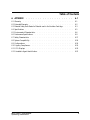
'%.%2!, $%3#2)04)/. 1.1 General Description
1-1
. . . . . . . . . . . . . . . . . . . . . . . . .
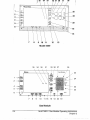
#/.42/,3 !.$ ).$)#!4/23 2.1 Front Panel . . . . . . . . . . . . . . . . . . . . . . . . . . . . .
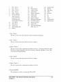
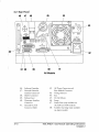
2.2 Rear Panel . . . . . . . . . . . . . . . . . . . . . . . . . . . . .
2-2
2-10
/0%2!4)/. 3.1
3.2
3.3
3.4
3.5
General Guidelines . . . . . . . . . . .
Initial Set Up . . . . . . . . . . . . .
Turning Power On . . . . . . . . . . .
Typical Operation . . . . . . . . . . .
Waveform Selection and Size . . . . . . .
3.5.1 Selection . . . . . . . . . . . .
3.5.2 Size . . . . . . . . . . . . . .
3.6 Gas-Trace Speed . . . . . . . . . . . .
3.7 Split Screen . . . . . . . . . . . . . .
3.8 Trend Time . . . . . . . . . . . . . .
3.9 Record . . . . . . . . . . . . . . .
3.10 Cal . . . . . . . . . . . . . . . .
3.11 Alarms . . . . . . . . . . . . . . .
3.12 Alarm Keys - Setting Alarms . . . . . .
3.12.1 Select, HI, and LO . . . . . . . .
3.12.2 Auto Set - Automatic Setting of Alarms
3.12.3 Audio - Mute . . . . . . . . . .
3.12.4 Audio - Volume . . . . . . . . .
3.13 Digital Displays . . . . . . . . . . .
3.14 Trend Displays . . . . . . . . . . . .
3.15 Sampling Flow Rate/O2 Cal Adjust Sequence
3.16 O2 Cell . . . . . . . . . . . . . . .
3.17 Sump . . . . . . . . . . . . . . .
3.18 Scrubber Cartridge . . . . . . . . . .
MULTINEX / Gas Module
Operating Instructions
.
.
.
.
.
.
.
.
.
.
.
.
.
.
.
.
.
.
.
.
.
.
.
.
.
.
.
.
.
.
.
.
.
.
.
.
.
.
.
.
.
.
.
.
.
.
.
.
.
.
.
.
.
.
.
.
.
.
.
.
.
.
.
.
.
.
.
.
.
.
.
.
.
.
.
.
.
.
.
.
.
.
.
.
.
.
.
.
.
.
.
.
.
.
.
.
.
.
.
.
.
.
.
.
.
.
.
.
.
.
.
.
.
.
.
.
.
.
.
.
.
.
.
.
.
.
.
.
.
.
.
.
.
.
.
.
.
.
.
.
.
.
.
.
.
.
.
.
.
.
.
.
.
.
.
.
.
.
.
.
.
.
.
.
.
.
.
.
.
.
.
.
.
.
.
.
.
.
.
.
.
.
.
.
.
.
.
.
.
.
.
.
.
.
.
.
.
.
.
.
.
.
.
.
.
.
.
.
.
.
.
.
.
.
.
.
.
.
.
.
.
.
.
.
.
.
.
.
.
.
.
.
.
.
.
.
.
.
.
.
.
.
.
.
.
.
.
.
.
.
.
.
.
.
.
.
.
.
.
.
.
.
.
.
.
.
.
.
.
.
.
.
.
.
.
.
.
.
.
.
.
.
.
.
.
.
.
.
.
.
.
.
.
.
.
.
.
.
.
.
.
.
.
.
.
.
.
.
.
.
.
.
.
.
.
.
.
.
.
.
.
.
.
.
.
.
.
.
.
.
.
.
.
.
.
.
.
.
.
.
.
.
.
.
.
.
.
.
.
.
.
.
.
.
.
.
.
.
.
.
3-1
3-2
3-3
3-4
3-9
3-9
3-9
3-10
3-10
3-11
3-11
3-12
3-12
3-14
3-15
3-15
3-16
3-16
3-17
3-18
3-18
3-20
3-20
3-20
i
3.19 Software Cartridge . . . . . . . . . . . . . . . . .
3.20 Intake and Exhaust Luers . . . . . . . . . . . . . . .
3.21 User Configuration . . . . . . . . . . . . . . . . .
3.21.1 User Configuration Mode . . . . . . . . . . . .
3.21.2 Typical Configuration Menu Sequence . . . . . . .
3.21.3 CO2/SaO2 Output Configuration . . . . . . . . .
3.22 Interfacing . . . . . . . . . . . . . . . . . . . .
3.22.1 With Datascope ACCUSAT . . . . . . . . . . .
3.22.2 Interfacing with the 3000 or 3000A Monitor . . . .
3.22.2.1 Software Compatibility : Multinex Plus / 3000 / 3000A
3.22.3 Connectors . . . . . . . . . . . . . . . . .
3.22.4 Interfacing to Personal Computers . . . . . . . . .
3.23 Optional Unit Configurations . . . . . . . . . . . . .
3.23.1 Units equipped with SaO2 (Model 4200) . . . . . .
3.23.2 Units Equipped with Anesthetic Agent (Model 4100ID)
3.24 SaO2 Sensor Selection . . . . . . . . . . . . . . . .
3.25 Performance Verification . . . . . . . . . . . . . . .
4ABLE OF #ONTENTS
.
.
.
.
.
.
.
.
.
.
.
.
.
.
.
.
.
.
.
.
.
.
.
.
.
.
.
.
.
.
.
.
.
.
.
.
.
.
.
.
.
.
.
.
.
.
.
.
.
.
.
.
.
.
.
.
.
.
.
.
.
.
.
.
.
.
.
.
.
.
.
.
.
.
.
.
.
.
.
.
.
.
.
.
.
.
.
.
.
.
.
.
.
.
.
.
.
.
.
.
.
.
.
.
.
.
.
.
.
.
.
.
.
.
.
.
.
.
.
.
.
.
.
.
.
.
.
.
.
.
.
.
.
.
.
.
.
.
.
.
.
.
.
.
.
.
.
.
.
.
.
.
.
3-20
3-20
3-21
3-21
3-24
3-25
3-25
3-25
3-26
3-26
3-27
3-29
3-29
3-29
3-30
3-31
3-36
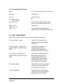
53%2 -!).4%.!.#% 4.1 Care and Cleaning of Monitor . . . . . . . . . . . . .
4.2 Replaceable Items . . . . . . . . . . . . . . . . . .
4.2.1 Catheters and Breathing Tube Adaptors . . . . . . .
4.2.2 O2 Cell . . . . . . . . . . . . . . . . . . .
4.2.3 Sump . . . . . . . . . . . . . . . . . . . .
4.2.4 Scrubber Cartridge . . . . . . . . . . . . . . .
4.2.5 Software Cartridge . . . . . . . . . . . . . . .
4.2.6 Fuses . . . . . . . . . . . . . . . . . . . .
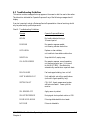
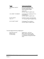
4.3 Troubleshooting Guidelines . . . . . . . . . . . . . .
4.4 Frequent "PURGING" Events due to Moisture in the Breathing
Circuit and/or Improperly Sized Accessories . . . . . . . .
.
.
.
.
.
.
.
.
.
.
.
.
.
.
.
.
.
.
.
.
.
.
.
.
.
.
.
.
.
.
.
.
.
.
.
.
.
.
.
.
.
.
.
.
.
.
.
.
.
.
.
.
.
.
.
.
.
.
.
.
.
.
.
.
.
.
.
.
.
.
.
.
.
.
.
.
.
.
.
.
.
4-1
4-1
4-2
4-2
4-3
4-3
4-4
4-4
4-5
. . . . . . . . . 4-8
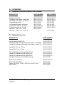
!##%33/2)%3 5.1 Standard Accessories . . . . . . .
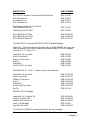
5.2 Optional Accessories . . . . . . .
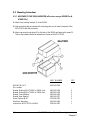
5.3 Mounting Instructions . . . . . .
5.3.1 Multinex to the 3000A Monitor
5.3.2 Multinex to Other Units . . .
5.3.3 Drawer Box Assembly . . . .
ii
.
.
.
.
.
.
.
.
.
.
.
.
.
.
.
.
.
.
.
.
.
.
.
.
.
.
.
.
.
.
.
.
.
.
.
.
.
.
.
.
.
.
.
.
.
.
.
.
.
.
.
.
.
.
.
.
.
.
.
.
.
.
.
.
.
.
.
.
.
.
.
.
.
.
.
.
.
.
.
.
.
.
.
.
.
.
.
.
.
.
.
.
.
.
.
.
.
.
.
.
.
.
.
.
.
.
.
.
.
.
.
.
.
.
5-1
5-1
5-4
5-4
5-5
5-6
MULTINEX / Gas Module
Operating Instructions
4ABLE OF #ONTENTS
!00%.$)8
6.1 Warranty . . . . . . . . . . . . . . . . . . . . . . .
6.2 Extended Warranty . . . . . . . . . . . . . . . . . . . .
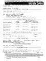
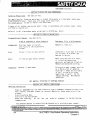
6.3 Material Safety Data Sheets for Material used in the Scrubber Cartridge
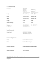
6.4 Specifications . . . . . . . . . . . . . . . . . . . . . .
6.5 Environmental Characteristics . . . . . . . . . . . . . . . .
6.6 Performance Specifications . . . . . . . . . . . . . . . . .
6.7 Safety Characteristics . . . . . . . . . . . . . . . . . . .
6.8 System Compatibility . . . . . . . . . . . . . . . . . . .
6.9 Configurations . . . . . . . . . . . . . . . . . . . . .
6.10 Agency Compliances . . . . . . . . . . . . . . . . . . .
6.11 CO2 Displays . . . . . . . . . . . . . . . . . . . . .
6.12 Anesthetic Agent Identification . . . . . . . . . . . . . . .
MULTINEX / Gas Module
Operating Instructions
.
.
.
.
.
.
.
.
.
.
.
.
.
.
.
.
.
.
.
.
.
.
.
.
.
.
.
.
.
.
.
.
.
.
.
.
.
.
.
.
.
.
.
.
.
.
.
.
.
.
.
.
.
.
.
.
.
.
.
.
.
.
.
.
.
.
.
.
.
.
.
.
6-1
6-2
6-3
6-5
6-6
6-8
6-17
6-18
6-18
6-19
6-20
6-21
iii
&/2%7/2$
This manual is intended to provide the information needed for proper operation of the Datascope
MULTINEX and GAS MODULE.
General knowledge of monitoring and an understanding of the features and functions of the
Datascope MULTINEX / GAS MODULE are prerequisites for its proper use.
DO NOT OPERATE THIS MONITOR BEFORE READING THESE INSTRUCTIONS.
Information for servicing this instrument is contained in the Datascope MULTINEX / Gas
Module Service Manual, Part No. 0070-00-0369. For additional information or assistance, please
contact an authorized Datascope representative in your area.
Federal Law restricts this device to sale by or on the order of a physician or other practitioner
licensed by state law to use or order the use of this device.
For external communication protocol see Service Manual Supplement: P/N 0070-00-0305,
MULTINEX Communication Protocol.
NOTE: In order to ensure the proper performance of your monitoring equipment and to prevent
the voiding of the warranty, it is recommended that only parts and accessories provided by
Datascope be used with your monitor.
3!&%49 #/.3)$%2!4)/.3
Please read and adhere to the following safety considerations regarding the use of this instrument.
7!2.).'3
Possible Explosion Hazard - This instrument is not explosion proof and should not be used in the
presence of flammable anesthetics.
Internal Electrical Shock Hazard - This unit does not contain any user-serviceable parts. Do not
remove instrument covers. Refer servicing to qualified personnel.
Trace Gas Hazard - A health hazard may exist when trace amounts of vaporized anesthetic agents are
chronically inspired by operating room personnel. (See Appendix A in NFPA 56A on Inhalation
Anesthetics.) During any procedure where such agents are employed, the MULTINEX / Gas Module
exhaust output should be connected to a medical gas-scavenging system.
Do not operate this monitor if: some or all of the displays fail to function properly, or the CRT
message "FAN FAILURE" occurs.
Insure that the total combined leakage currents do not exceed safe limits.
DO NOT change the voltage selector.
Use only MULTINEX / Gas Module software cartridges in this unit.
MULTINEX / Gas Module
Operating Instructions
v
#!54)/.3
NOTE: Prior to applying des. or sev., select agent id disabled mode, then select agent. Failure to
do so will cause erroneous CO2, N2O and agent readings.
Never place fluids on top of the monitor.
Always place the monitor on a flat, rigid surface.
Observe all CAUTION and WARNING labels.
Replace the fuses with specified type and rating.
Grounding reliability can only be achieved when the monitor is connected to an equivalant receptacle
marked "Hospital Grade".
RS232 DISCLAIMER - Connection of non-isolated devices to the RS232 Connector on this unit
may cause chassis leakage to exceed the specification standards.
EXTERNAL OXIMETER DISCLAIMER - Connection of non-isolated devices to the external
oximeter connector on this unit may cause chassis leakage to exceed the specificaiton standards.
5.0!#+).'
Remove the instrument from the shipping carton and examine it for signs of shipping damage. Save
all packing materials, invoice, and bill of lading. These may be required to process a claim with the
carrier. Check all materials against the packing list. Contact the Datascope Service Department
(800) 288-2121 for prompt assistance in resolving shipping problems.
vi
MULTINEX / Gas Module
Operating Instructions
3%26)#).' ).&/2-!4)/.
Datascope maintains a network of service representatives and factory-trained distributors. Prior to
requesting service, perform a complete operational check of the instrument to verify proper control
settings. If operational problems continue to exist, contact the Datascope Service Department (800)
288-2121 for assistance in determining the nearest field service location.
Please include the instrument model number, the serial number, and a description of the problem
with all requests for service.
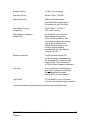
Any questions regarding the warranty should be directed to:
$OMESTIC /FFICE
Service Manager
Datascope Corp.
580 Winters Ave.
Paramus, NJ 07652
(800) 288-2121
)NTERNATIONAL /FFICES
Service Manager
Datascope B.V.
Dr. W van Royenstraat 8
P.O. Box 26
3870 CA Hoevelaken
Holland
Phone: 31(3325)44911
Fax: 31(3325)72974
Service Manager
Datascope GmbH
Zeppelinstraße 2-4
D-64625 Bensheim
Germany
Phone: 49(6251)1705-0
Fax: 49(6251)67877
Service Manager
Datascope Medical Co., Ltd.
Lakeview Court
Spitfire Close
Ermine Business Park
Huntingdon, England
Cambs PE186XR
Phone: 44 1 (480)433477
Fax: 44 1 (480)434051
Service Manager
Datascope S.A.R.L.
Immeuble Rond Point 93
65 Avenue DU General Gallieni
93100 Montreuil-sous-Bois
France
Phone: 33(1)45139150
Fax: 33(1)45139151
Copyright © Datascope Corp., 1992. Printed in USA. All rights reserved. Contents of this
publication may not be reproduced in any form without permission of Datascope Corp.
MULTINEX / Gas Module
Operating Instructions
vii
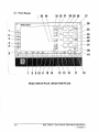
/0%2!4)/.
This section of the Operating Instructions provides general guidelines and step-by-step
instructions for the proper use of the MULTINEX / Gas Module.
Perform all instructions in the order given. Do not omit any instructions. Numbers in
parenthesis identify the controls and indicators previously described in Chapter 2, Controls
and Indicators.
'ENERAL 'UIDELINES
The MULTINEX / Gas Module calculates and displays Inspired O2, End-Tidal CO2,
Inspired CO2, Inspired and Expired N2O, and Respiration Rate.
Inspired and Expired Anesthetic Agent data is only available on units with Agent capability.
NOTE: Prior to applying des. or sev., select agent id disabled mode, then select agent. Failure
to do so will cause erroneous CO2, N2O and agent readings.
SaO2 and Pulse Rate data is only available on the 4000 Plus, 4000ID Plus and 4200 models.
Operation of the MULTINEX / Gas Module is based on breath-by-breath measurements via a
catheter and a breathing-tube adaptor.
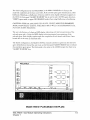
The 7-inch raster type CRT displays a maximum of three trace waveforms, trended data,
alarm limits, and user-messages.
Trace 1 always displays the CO2 waveform.
Trace 2 and Trace 3 are used to display the other available waveforms, i.e., N2O, Pleth, and
Cascaded CO2 (CO2DY). Trace 2 is always the Agent waveform on units with Agent capability.
Each trace area is outlined and scaled with it’s appropriate units.
MULTINEX / Gas Module Operating Instructions
Chapter 3
3-1
)NITIAL 3ET 5P
1. Set the front panel AC POWER ON/OFF switch (6) OFF.
2. Check the serial number label and confirm proper voltage configuration. If the instrument
voltage selection is not for your particular application, contact a Datascope Service
Representative or qualified hospital personnel.
3. If interfacing with other equipment, attach the appropriate interface cable(s) between the
MULTINEX / Gas Module rear panel INTERFACE connector and the corresponding
INTERFACE connector(s) on the peripheral instrument(s).
4. Attach the line cord to the ac power connector (42) on the MULTINEX and to a properly
grounded 3-wire ac receptacle. DO NOT use any adaptors to defeat the U-ground of the
cord set.
WARNING: Insure that the total combined leakage currents do not exceed safe limits.
5. Interface the supplied catheter with the breathing-tube adaptor. Follow the instructions
included in each package.
6. Attach the supplied catheter (with the breathing tube adaptor) to the sample connector
located on the front panel (18). Follow the instructions included in the catheter package.
7. Check for a clean sump. The sump is a disposable item that can be replaced if
contaminated. See Section 4.2.3, Sump.
8. Check the sump and O2 cell for tightness to avoid system leaks.
3-2
MULTINEX / Gas Module Operating Instructions
Chapter 3
4URNING 0OWER /.
1. Attach the catheter to the MULTINEX / Gas Module before turning the unit ON.
2. Turn the front panel ON/OFF switch (6) ON.
Observe the illumination of the CRT and digital displays and two audible beeps. The system
performs a self-test before proceeding with monitoring. If a problem exists a message will
appear identifying it. In some cases a prompt will ask the operator if they wish to continue
monitoring (of SaO2 only). See Section 4.3 for messages and responses.
O2 cell calibration is the next step in this process and takes two minutes to complete. During
O2 cell calibration, two or three flat traces appear on the screen with the message "O2CAL:
XXX", where XXX denotes the time remaining in seconds until the completion of the O2
Cal. After the O2 Cal is complete, the unit calibrates the gas channels and operation begins.
The agent channel is not operational for the first five minutes.
The unit is fully operational (reaches full specification) (including agent) after a 5-minute
warm-up period. Additional calibrations are recommended at 30 minutes and any time the
operator feels the need to re-calibrate (see drift specification).
WARNING: When using the MULTINEX / Gas Module prior to a warm-up period of 5
minutes, its accuracy may not meet specification.
WARNING: Evaporated alcohol or organic vapor will affect the reading of the Halothane, Enflurane
or Isoflurane display. Alcohol in the patient’s breath cannot be distinguished from an anesthetic agent. A
reading of the patient’s expired breath on the MULTINEX / Gas Module display should be taken before the
administration of an anesthetic agent to establish the presence of alcohol or organic agents.
MULTINEX / Gas Module Operating Instructions
Chapter 3
3-3
4YPICAL /PERATION
NOTE: The following sequence is presented only to describe to the operator a simple, straightforward method for using the multinex and does not take the place of other instructions
described in this manual.
1. Set Up
Connect an ac power cord to the AC Power Connector (42) and into an ac receptacle.
2. Catheter Connection
Attach the catheter to the Sample Connector (18). Attach an appropriate breathing tube
adaptor to the catheter.
3. Sensor Connection (Models with SaO2 option only)
Plug the appropriate Datascope SaO2 sensor into the Patient Connector (17).
4. Main Power Switch
Press the POWER ON/OFF switch (6) to the ON position.
The unit begins a "self-check" and a two minute calibration for the O2 cell, followed by a
calibration of the CO2, N2O and Agent channels.
Auto-calibration occurs during the first 5 minutes.
5. Agent Analysis
a. Agent ID Versions (Models 4000ID Plus, 4100ID Plus) Select the mode of agent
identification desired, AUTO, VERIFY or ID DISABLED, using AGENT ID MODE
(7). If VERIFY or ID DISABLED is selected, use AGENT SELECT (19) to indicate
the agent being delivered.
NOTE: When using Sevoflurane or Suprane, the ID DISABLED mode must be used.
The MULTINEX will not AUTO ID or VERIFY Sevoflurane or Suprane.
NOTE: Prior to applying des. or sev., select agent id disabled mode, then select agent.
Failure to do so will cause erroneous CO2, N2O and agent readings.
b. Agent Versions (Models 4000 Plus, 4100 Plus & Gas Module)
Use AGENT SELECT (19) to indicate the agent being delivered.
3-4
MULTINEX / Gas Module Operating Instructions
Chapter 3
6. Operation
The unit contains pre-programmed selections for trace size, speed, selection, trend display,
and alarms. The unit is ready to operate immediately after calibration.
To change any of these functions, press the appropriate key (see Sections 3.5, 3.6, 3.7, and
3.8 for more details).
a. Trace - Select:
• Press the appropriate key (Select - Trace 2 (3) or Select - Trace 3 (5)) to select the
desired trace.
• Trace 2 (3) - Displays cascaded CO2*, N2O, or PLETH (SaO2 versions only) waveform.
• Trace 3 (5) - Displays a CO2, N2O, or PLETH (SaO2 versions only) waveform.
NOTE: Trace 1 always displays a CO2 trace. Trace 2 always displays AGENT on units
that measure anesthetic agents.
b. Trace - Size:
• Press the appropriate key (Size - Trace 1 (1), Size - Trace 2 (2), or Size - Trace 3
(4)) to select the size of the trace.
c. Gas Trace Speed (8):
• Press to change the speed of all the displayed gases.
d. Split Screen (9):
• Press to change a portion of the waveform display to a trend presentation. Depressing
the key varies the proportion of the displayed waveform and trend.
e. Trend Time (10):
• Selects a time period for the display of trended data. Hold for 3 seconds to clear.
*Cascaded CO2 allows the CO2 waveform on trace 1 to be moved to Trace 2 or 3 as Trace 1 is
being updated.
MULTINEX / Gas Module Operating Instructions
Chapter 3
3-5
7. Alarms
a. Select (33):
• Press to display the alarm parameters on the screen.
• Change the alarm settings by pressing the HI (32) or LO (31) keys.
• Press SELECT (33) to index through the alarm selections. The alarms are set as
indicated on the display. The displayed limits disappear after 15 seconds.
• Upon violation or depression of the SELECT key (33), the limits are recalled on the
display.
b. Audio Mute (16):
• Press once to silence the audio tone of a violated alarm for two minutes.
• Depress twice within three seconds to cancel all audio alarms for two
minutes.
c. Audio Volume (15):
• Controls the sound level of the tone.
d. Auto Set (30):
• Press to automatically set the alarms (CO2, Pulse Rate, and Inspired Agent only)
based on the last five minutes of patient data. Hold for 3 seconds to reset alarms to
default settings.
e. Cal (13):
• This button can be used to manually calibrate the CO2, N2O and Agent channels
whenever needed (see drift specification). It is recommended that the unit be
calibrated once at 30 minutes and periodically after that. Note that the corresponding
data and displays do not update during a calibration.
• It is normal for the MULTINEX / Gas Module to automatically recalibrate on a
periodic basis, if the measurement bench starts to drift.
3-6
MULTINEX / Gas Module Operating Instructions
Chapter 3
8. Agent (units with Agent capability only)
a. Agent ID Mode (7)
• Selects the mode of agent identification (4000ID Plus & 4100ID Plus).
• If the AUTO mode is selected and no agent is present, the word "READY"
displays on the CRT above the agent trace area. Nothing is illuminated in the
agent display window (21). When an Agent is detected, the unit will replace the
"READY" message with the name of the Agent identified.
NOTE: Prior to applying des. or sev., select agent id disabled mode, then select
agent. Failure to do so will cause erroneous CO2, N2O and agent readings.
• If the VERIFY mode is chosen, the agent selected with the AGENT SELECT key
(19) is displayed on the CRT above the agent trace area. When the Agent identified
is the same as that selected for verification, a beep tone will be sounded and the
agent name listed on the CRT. Otherwise, the message "WRONG AGENT" will
appear.
NOTE: Prior to applying des. or sev., select agent id disabled mode, then select
agent. Failure to do so will cause erroneous CO2, N2O and agent readings.
• The DISABLE mode is used to disable the ID section and allows the Sevoflurane or
Suprane to be selected. These agents must be selected manually and cannot be
automatically identified.
b. Agent Select (19) (active in VERIFY and ID DISABLED Mode only):
• Indicates the selected anesthetic agent. Press AGENT SELECT (19)
until the selected agent is displayed on the CRT above Trace 2.
NOTE: N2O is selected for CRT display via user-configuration. See Section 3.19.
NOTE: When monitoring one agent and then changing to another, the agent trend
display will update for the new agent with a bar between the agent.
NOTE: Prior to applying des. or sev., select agent id disabled mode, then select agent.
Failure to do so will cause erroneous CO2, N2O and agent readings.
c. % End Tidal (22)
• Indicates end tidal concentrations of the selected agent (0-8%). Data updates at the
completion of each breath. If new breath data is the same as old breath data the
display flickers. Flickering indicates a new reading.
MULTINEX / Gas Module Operating Instructions
Chapter 3
3-7
d. % Inspired (20):
• Indicates inspired concentrations of the selected agent (0-8%). Data updates at the
completion of each breath. If new breath data is the same as old breath data the
display flickers. Flickering indicates a new reading.
9. SaO2
a. SaO2 (28)
• Indicates SaO2 concentrations in units of percent (0-99%). Data updates every two
seconds.
b. Pulse Rate (28):
• Indicates the SaO2 pulse rate in beats per minute (30-250). Data updates every two
seconds.
c. Beep Volume (14):
• Adjusts pulse volume level. Press to sound the beep at the present volume. Press
twice within three seconds to change the selected beep volume.
3-8
MULTINEX / Gas Module Operating Instructions
Chapter 3
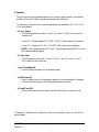
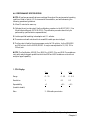
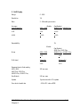
7AVEFORM 3ELECTION AND 3IZE
There are five front panel keys (1,2,3,4,5) that control the selection and sizes of the displayed
waveforms.
If a selected waveform is not valid for a particular monitor or if that selection already is
displayed on another trace, that selection is skipped and the next waveform in the sequence is
displayed.
3ELECTION
Trace 1 always displays the CO2 waveform.
Trace 2 indexes through the following choices (on non-agent units only): N2O, Pleth, CO2
Delay (Cascaded CO2), and Off. Agent units use Trace 2 to display Agent only.
Trace 3 indexes through Pleth, N2O, and Agent.
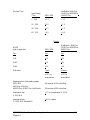
3IZE
The following is a list of the available size selections for the various traces.
CO2:
TORR:
%:
KPA:
N2O:
% Agent:
Trends**:
SaO2(%):
Pulse**:
Pleth:
Scale Range
0 - 80*,
0 - 10*,
0 - 10*,
0 - 40*,
0 - 20*,
0 - 40,
0 - 5,
0 - 5,
0 - 100,
0 - 8,
0 - 100
0 - 12
0 - 12
0 - 60
0-3
0 - 100
0 - 250*
1, 2, 4*, 8
* default values
** Trend SaO2 and Pulse are available on all models but the 4100 Plus, 4300 and the Gas
Module require external oximeters approved to work with MULTINEX. Trend only appears
when selected.
MULTINEX / Gas Module Operating Instructions
Chapter 3
3-9
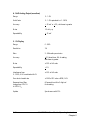
'AS4RACE 3PEED 1. Press Gas-Trace (8) to change the speed of the erase bar devoted to any gas measurements
(CO2, N2O, or Agent).
The setting changes the gas trace speed for all displayed gases, (individual settings for
different waveforms can not be made.)
The speed of the erase bar can be set to 1, 5, 10, 12.5*, or 25 mm/s.
The plethysmograph trace speed is fixed at 25 mm/s, regardless of the Gas Trace Speed
setting.
3PLIT 3CREEN 1. Press Split Screen (9) to change the proportion of the display dedicated to waveform data
and trended data.
Split Screen combinations are as follows:
Waveform/Trend (%)
100/0 (all waveform, no trend)
75/25*
50/50
25/75
0/100 (no waveform, all trend)
The selected split screen setting affects all displayed waveforms.
* default values
3-10
MULTINEX / Gas Module Operating Instructions
Chapter 3
4REND 4IME 1. Press Trend Time (10) to change the time scales for trend presentations.
The available time scales are as follows:
10 min, 30 min*, 1 hr, 2 hr, 4 hr, 8 hr, 12 hr
(Trend information is always maintained for each parameter, even when not displayed.)
The selected trend time is displayed to fit the trend space allocated by the split screen selection.
The Trend Time setting selection applies to all waveforms.
2. Press Trend Time for three or more seconds to clear the trend memory.
When changing alarm limits, a visible gap may appear in the SaO2 and Pulse Rate trend display.
This indicates that the data point for that position was not recorded.
NOTE: The SaO2 trend area displays two parameters, % SaO2 and Pulse Rate. The SaO2
waveform is a plethysmograph waveform.
2ECORD 1. Press Record (12) with the 2000RS set for "CO2" and "Auto" to print the real-time
capnogram and the available digital information.
To record real-time trend of CO2, the recorder should be set to run at 1 or 5 mm/min. and
CO2 selected.
Using the user configuration mode, % SaO2 can be super-imposed on the CO2 real-time
trend.
* default values
MULTINEX / Gas Module Operating Instructions
Chapter 3
3-11
#AL During MULTINEX / Gas Module operation, an internal calibration process can be
performed for CO2, N2O, and Agent.
1. Press Cal (13) to begin this calibration process.
WARNING: Parameters are not monitored during this calibration.
It is normal for the MULTINEX / Gas Module to automatically recalibrate on a periodic
basis, if the measurement bench begins to drift.
!LARMS
Visual alarm data is provided on the right side of the CRT. This data appears upon initial
power-up and disappears after 15 seconds.
Press SELECT (33) to recall alarm data at any time. Alarm data is also displayed when
AUTO SET (30) is pressed. This information is displayed for 15 seconds.
Alarm limits are considered violated if the displayed value equals or exceeds the upper limit
or is equal to or below the lower alarm limit.
Upon an alarm violation, alarm limits appear with the violated parameter highlighted.
The alarm limit visual indicators will remain until the alarm condition no longer exists.
3-12
MULTINEX / Gas Module Operating Instructions
Chapter 3
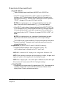
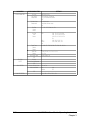
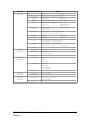
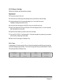
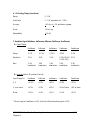
The following chart outlines the available alarm parameters, the low and high alarm ranges,
and the audio tones associated with the alarm violation.
Alarm Parameters, Range, and Audio Response
Displays on
Models
All
Parameter
Range
ETCO2 (Torr)
All
Inspired O2 (%)
All
Inspired CO2
(Torr)
Resp. Rate (bpm)
All
4000ID Plus
4000 Plus
4200
4000ID Plus
4000 Plus
4200
4000ID Plus
4000 Plus
4100 Plus
Gas Module
4000ID Plus
4000 Plus
4200
4000ID Plus
4000ID Plus
SaO2 (% SaO2)
Pulse Rate (bpm)
Inspired Agent (%)
Sensor Off
Check Sensor
No Pulse
Wrong Agent
Mixed Agent
Default
Audio Response
High - 20-80
Low - 0-60, Off
High - 40-95, Off
Low - 18, 20-80
High - 0-25,
Low - 0-25, Off
High - 5-95, Off
Low - 2-10, Off
High - 80-99, Off
Low - 50-85, Off
86-95, Off
Hi - 100-250, Off
Low - 30-99, Off
Units
Increments
5
5
5
5
5
5
5
1
1
5
1
5
5
80
Off
Off
18
15
Off
Off
2
Off
85
Off
Off
Continuous on violation
Continuous on violation
Beep 1/4 s; every 10 s
Continuous on violation
Beep 1/4 s;on violation
Beep 1/4 s; every 10 s
Beep 1/4 s; every 10 s
Beep 1/4 s; every 10 s
Continuous on violation
Continuous on violation
Continuous on violation
Continuous on violation
Continuous on violation
High - 0-20
Low - 0-3, Off
1
1
6
Off
Continuous on violation
Beep 1/4 s; every 10 s
n/a
n/a
n/a
n/a
n/a
n/a
n/a
n/a
n/a
4 second warning tone
4 second warning tone
2 beeps
NOTES:
• SaO2 and Pulse Rate alarms are not available when using an external oximeter.
Warning tones and SaO2 messages will also not be present.
• LED displays always flash once per second during each violation. Violated alarm
limit is displayed in reverse graphics on the CRT.
• CO2 alarms can also be set in % or KPa, but only to whole numbers (1%, 2%,
etc...).
• Alarm limits are considered violated if the displayed value equals or exceeds the
upper alarm limit or is equal to or below the lower alarm limit.
MULTINEX / Gas Module Operating Instructions
Chapter 3
3-13
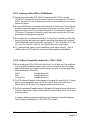
The MULTINEX / Gas Module alarms on all alarm limit violations and for the following
apnea conditions:
Breath not Detected During Normal Monitoring
after: 28-32 seconds
43-47 seconds
60 seconds
Audio Response
A 1/4 second audible alarm tone at the selected alarm
loudness
Two 1/4 second audible alarm tones at the selected alarm loudness
A 4 second audible alarm tone at maximum volume followed by a 16
second audible alarm tone at the selected alarm loudness. the total 20
seconds of alarm is modulated at 1 Hz.
If a valid breath is detected during this sequence the alarm timer and CRT message reset.
Initially, the apnea alarm is disabled until the unit detects two initial breaths.
NOTE: During a cal sequence apnea conditions are detected but, alarm is delayed until cal is
completed.
!LARM +EYS 3ETTING !LARMS
Six keys are used to control the alarm function of the MULTINEX / Gas Module. They are:
AUTO SET (30), SELECT (33), HI (32), LO (31), AUDIO MUTE (16), and AUDIO
VOLUME (15).
Alarms can be set manually by using the SELECT (33), HI (32), and LO (31) keys, or
automatically.
3-14
MULTINEX / Gas Module Operating Instructions
Chapter 3
3%, () AND ,/
The SELECT, HI, and LO keys are used to manually set the alarm limits.
1. Press SELECT (33) until the desired alarm parameter highlights in reverse graphics.
2. Press HI (32) until the desired high alarm limit appears.
3. Press LO (31) until the desired low alarm limit appears.
4. Press SELECT (33) to repeat the above-stated process for the remaining parameters.
If SELECT remains inactive for two seconds, the currently displayed alarm limits set
automatically.
!UTO 3ET !UTOMATIC 3ETTING OF !LARMS
The Auto Set feature can be used after collecting five minutes of patient data. The unit
automatically calculates alarm limits for CO2, Agent, and Pulse Rate, based on 20% above
and below the mean, and automatically updates the limit displays.
1. Press Auto Set (30) to automatically set the alarm limits.
The alarm limits are based on the most recent five minutes of patient data.
Each time AUTO SET (30) is pressed the alarm limits are recalculated based on the past four
minutes of patient data. Once set, the alarms are fixed and do not change until this key is
pressed again or when the limits are manually changed.
"AUTO ALARMS SET" is displayed on the screen for 20 seconds after all limits have been
set. The alarm data will be displayed on the right side of the CRT.
NOTE: Assure that the message "AUTO ALARMS SET" appears on the CRT. If the
message does not appear either five minutes of data is not available or alarms were not set.
Press AUTO SET (30) again or wait for data to accumulate.
MULTINEX / Gas Module Operating Instructions
Chapter 3
3-15
The alarms do not update with new data. To set new auto alarm values, press AUTO SET
(30) again. This can be done at any time during monitor use.
NOTE: The Pulse Rate Auto Alarms are set 2 and 8 seconds after the "AUTO ALARM
SET" message is displayed.
2. Press and hold AUTO SET (30) for 3 seconds to reset alarm limits to the default settings.
An "AUTO ALARMS RESET" message will appear on the CRT for 20 seconds.
!UDIO -UTE
The AUDIO MUTE (16) key is used to silence the audio tone produced by a violated alarm
limit.
1. Press AUDIO MUTE (16) to silence the audio tone. The alarm is muted for two minutes.
The message "MUTED" is displayed on the CRT during this time.
2. Press AUDIO MUTE (16) twice within three seconds to disable all the alarms for two
minutes. The message "ALL MUTED" is displayed on the CRT during this time.
Audio Mute is automatically canceled during the two minute time period if the parameters
come back within acceptable limits and if all the alarms have not been "ALL MUTED".
Violated alarm limits are displayed in reverse graphics and the corresponding LEDs are
flashed at a 1 Hz rate.
!UDIO 6OLUME
The AUDIO VOLUME key (15) is used to control the loudness of the alarm tone.
1. Press AUDIO VOLUME (15) to sound the tone at the present alarm volume.
2. Press AUDIO VOLUME twice within 3 seconds to change the alarm audio level.
A CRT display, to the left of the AUDIO VOLUME key, provides a visual indication of
audio loudness. The OFF selection is the only level which remains displayed.
The alarm volume range is: OFF, Low, Medium, and High. The default is set at Low.
The audio volume level is displayed for 15 seconds.
3-16
MULTINEX / Gas Module Operating Instructions
Chapter 3
$IGITAL $ISPLAYS
The digital displays for ETCO2, Inspired CO2, Inspired O2, and Respiration Rate are each
shown in a separate 2-digit, LED. The digital displays for Inspired and Expired N2O are each
shown in a separate 2-digit CRT display (when alarms not visible).
The MULTINEX / Gas Module will first display instantaneous readings of Inspired and Expired
CO2 (Mode A) until the detection of two valid breaths (Mode B). Updated values for all the
parameters are then displayed at the completion of each breath. (Breath completion is defined
by the CO2 channel). N2O and agent values synchronize with CO2.
The unit switches to Mode A whenever a breath is not detected for 30 seconds. Additionally,
Respiration Rate (23) is blank whenever a breath is not detected within a period of two times
the immediate previous breath rate period.
The unit can be user-configured to display CO2 values that are compensated for water vapor
and/or altitude (see section 3.21.1). When either of these options are selected, the CO2
header above Trace 1 changes as shown below:
Header Display
CO2
CO2W
PCO2
PCO2W
Compensation for Water Vapor?
No
Yes
No
Yes
Altitude?
Yes
Yes
No
No
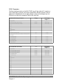
The Digital Displays chart, on pages 3-19 and 3-20, describes specific information for each
parameter.
The digital displays flicker upon breath completion if the updated data remains the same.
MULTINEX / Gas Module Operating Instructions
Chapter 3
3-17
4REND $ISPLAYS
Trend information for the gas parameters, CO2, N2O, and anesthetic agent, are displayed to
the right of their respective real time waveforms. A single vertical line can represent a single
breath, or the average of multiple breaths occurring over a period of time. The period of time
represented by a single vertical trend line depends on the SPLIT SCREEN trend percentage
and the TREND TIME selected.
Trend information for the SaO2 and pulse rate are displayed together on the right of the
plethysmograph waveform. As trend data accumulates the upper set of points represent the
SaO2 trend. The range of the SaO2 trend display is the entire vertical size of the rectangle
that encloses it, with the top line representing 100% SaO2, and the bottom line representing
60% SaO2.
The lower set of data represents the pulse rate trend. The range for this parameter is defined
similarly to the SaO2, with the top line representing 250 BPM and the bottom line
representing 0 BPM.
For all trend displays, the earliest information appears farthest to the right with the most
recent information appearing at the left of the trend partition.
3AMPLING &LOW 2ATE/ #AL !DJUST 3EQUENCE
1. To display the sampling flow rate, first press the ALARM SELECT key (33), then press the
RIGHT HIDDEN key (11). Use the ALARM HI key (32) to change the sampling flow
rate to another selection. The monitor will default to the originally displayed flow rate at
each power up unless changed in the user configuration mode.
2. The O2 CAL ADJUST +/- is a utility that enables the operator, while in the run mode, to
adjust the O2 display within the O2 accuracy tolerance.
To enter the O2 CAL ADJUST +/- mode, press the ALARM SELECT key (33), then press
the RIGHT HIDDEN key (11). Use the ALARM SELECT key to highlight O2 CAL
ADJUST +/-. Adjust O2 display by pressing the HI and/or LO keys to raise or lower the
displayed O2 reading at each power up.
3-18
MULTINEX / Gas Module Operating Instructions
Chapter 3
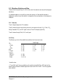
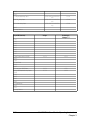
Digital Displays
Displays at end of
Indicates new
each breath in
breath but same
units of
breath data
display
0-1 %
flickers
0.1 KPA
1 TORR
Range
Display
ETCO2
0-76 TORR*
0-10%
0-10 KPA
2-digit
amber LED
Insp.
CO2**
0-76 TORR
0-10%
0-10 KPA
0-99%
2-digit
amber LED
0-98
breaths/min
0-99%
2-digit
amber LED
2-digit CRT
display
2-digit CRT
display
1 BPM
2-digit
amber LED
2-digit
amber LED
1%
Insp.
O2
Resp. Rate
Insp.
N2O
Exp.
N2O
0-99%
2-digit
amber LED
0-1 %
0.1 KPA
1 TORR
1%
1%
1%
Alarm Limit
Violation
Apnea Detection
display flashes
at 1 Hz
shows current
instantaneous level of
Exp’d CO2 (Mode A)
until detection of 2 new
valid breaths (Mode B)
display
blanks
display
flickers
display flashes
at 1 Hz
display
flickers
display flashes
at 1 Hz
display
flickers
display
flickers
display
flickers
display flashes
at 1 Hz
display
flickers
display
flickers
display flashes
at 1 Hz
display flashes
at 1 Hz
SaO2
0-99%
Agent ET
0-7%, Halothane
0-7.5%,Enflurane
0-7.5%,Isoflorane
0-20%,Desflurane
0-9%,Sevoflurane
Agent
Inspired
0-7%, Halothane
0-7.5%,Enflurane
0-7.5%,Isoflorane
0-20%,Desflurane
0-9%,Sevoflurane
2-digit
amber LED
.1%
Desflurane - .1%
(0-9.9%)
1% (10-20%)
display
flickers
display flashes
at 1 Hz
Pulse
Rate
30-250
BPM
2-digit
amber LED
1 BPM
display
flickers
display flashes
at 1 Hz
.1%
Desflurane - .1%
(0-9.9%)
1% (10-20%)
shows current
instantaneous level of
Insp. O2 (Mode A)
until detection of 2 new
valid breaths ( Mode B)
displays
blanks*
displays
blanks
shows current
instantaneous level of
Exp. N2O (Mode A)
until detection of 2 new
valid breaths ( Mode B)
shows current
instantaneous level of
Agent ET (Mode A)
until detection of 2 new
valid breaths ( Mode B)
displays
blanks
* Display also blanks if breaths are not detected within a period of two times the previous
breath rate period.
** CO2 readings can be compensated for water vapor and/or altitude via the user-configuration.
(See Section 3.21.1 and 6.4 for details)
MULTINEX / Gas Module Operating Instructions
Chapter 3
3-19
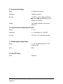
/ #ELL The O2 cell is used to determine the concentration of Inspired O2. Replace the O2 cell
whenever "--" appears in the O2 display following the power-up O2 Cal. See Section 4.4,
Replaceable Items.
3UMP The disposable sump is used to collect fluids that enter the unit. It should be checked after
each use. Replace or empty the sump when full. See Section 4.4, Replaceable Items.
3CRUBBER #ARTRIDGE The scrubber cartridge is used to accurately calibrate the CO2 channel on Agent units.
Replace the cartridge every 6 months or whenever a CRT message directs you to do so. See
Section 4.4, Replaceable Items.
3OFTWARE #ARTRIDGE The unit has incorporated, on the rear panel, a user-replaceable software cartridge. This
provides the operator with easy acess for software upgrade/replacement. Replace the cartridge
when necessary. See Section 4.4, Replaceable Items. NOTE: Ensure that the correct software
cartridge is being used with the model MULTINEX it is intended to be used with.
)NTAKE AND %XHAUST ,UERS The Intake Luer is used to sample room air to establish calibration accuracy for the various
gas sensors. Do not block or inhibit the flow of air through this port.
The Exhaust Luer is provided as a waste gas port, outputting to the scavenge gas input on
anesthesia machines. Do not block or inhibit the flow of gas, or pull a constant vacuum
greater than 1 mmHg.
3-20
MULTINEX / Gas Module Operating Instructions
Chapter 3
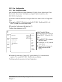
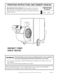
5SER #ONFIGURATION
5SER #ONFIGURATION -ODE
User-configuration menus for Display Parameters, CO2/SaO2 Output, Audio Control, Flow
Rate Control, Alarm Limits, Trace Options, and Agent Default are available on the
MULTINEX / Gas Module.
Access each of the above-stated menus through the Main Menu when in the User-Configuration
Mode.
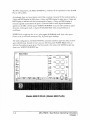
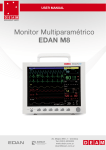
1. Press and hold SELECT (33) while turning the MULTINEX / Gas Module ON. Hold
SELECT pressed until the first beep is heard.
2. Choose User Configuration (left hidden key (7)).
The Main Menu displays on the CRT.
ALARMS
TRACE 1
SIZE
MAIN MENU
TRACE 2
SIZE
Display Parameters
CO2/SaO2 Output
SELECT
Enter
SELECT
HI
LOW
3. Press SELECT (33) to choose a
particular menu.
Audio Control
Flow Rate Control
TRACE 3
SIZE
Select
SELECT and ENTER are
displayed on the CRT next to the
Alarm SELECT (33) and HI (32)
keys.
AUTO
SET
Exit
AUDIO
MUTE
SELECT
AUDIO
VOLUME
4. Press "Enter" (HI (32) to access
menu choice.
5. Choose "Exit" in the menu to
obtain the previous menu
display.
6. Proceed to the main menu. Choose EXIT (right hidden key (11)) to resume normal
operation. The normal MULTINEX / Gas Module screen displays.
The following lists the menus found in User-Configuration.
MULTINEX / Gas Module Operating Instructions
Chapter 3
3-21
MAIN MENU
DISPLAY PARAMETERS
CO2/SaO2
OUTPUT
AUDIO CONTROL
FLOW RATE CONTROL
3-22
CONFIGURABLE ITEMS
SETTINGS
TORR, KPA, %, Exit
CO2 Units
CO2 at sea level (760mmHg)
CO2 Pressure
Compensation
CO2 at local barometric pressure
Exit
No compensation
CO2 Water Vapor
Compensation
Compensate for water vapor
Exit
1, 5, 10, 12.5, 25mm/sec, Exit
Gas Trace
Speed
Default
Gas Trace
CO2:
0-40 Torr, 0-5 KPA, 0-5%
Scale
0-80 Torr, 0-10 KPA, 0-10%
Default
0-100 Torr, 0-12 KPA, 0-12%
Exit
0-40, 0-60, 0-100, Exit
N2O:
AGENT:
0-2%, 0-4%, 0-8%*, Exit
Exit
Trend/Trace
0/100%, 25/75%, 50/50%, 75/25%, 100/0%, Exit
Partition
Default
Trend Time
10 min, 30 min, 1 hr, 2 hr, 4 hr, 8 hr,
Default
12hr, Exit
Disable, Enable, Exit
N2O Display Option
EXIT
CO2 Only
CO2/SaO2 Multiplexed
EXIT
Minimum Default Volume Off, Low, Exit
Audio Level Default
Low
High
Medium
Exit
EXIT
50 cc, 100 cc, 150 cc, 200 cc, Exit
MULTINEX / Gas Module Operating Instructions
Chapter 3
MAIN MENU
ALARM LIMITS
CONFIGURABLE ITEMS
InspCO2 (TORR)
InspN2O
InspAgent
SaO2
Pulse Rate
ETCO2 (TORR)
ExpN2O
ExpAgent
FIO2
Resp Rate
TRACE OPTION
(Agent Models)
TRACE OPTION
(Non-Agent Models)
EXIT
2 Trace Mode
3 Trace Mode
EXIT
2 Trace Mode
3 Trace Mode
AGENT DEFAULT
(Agent Models)
AGENT DEFAULT
(Agent Models)
EXIT
Agent Monitored
EXIT
Agent ID Mode
SETTINGS
HI SCALE
LO SCALE
00,05,10,15,20,25 00,05,10,15,20,25,OFF
Not Available
Not Available
00,01,02,03,04,05,06 ...20
00,01,02,03,OFF
OFF,80,81,82,83,84, 50,55,60,65,70,75,
85,86,87,...99
80,85,86,87,88,89,90
91,92,93,94,95
100,105,110,115,
OFF,30,35,40,45,50,
120,125,130,...250 55,60,...100
20,25,30,35,40,45, OFF,00,05,10,15,20,25,
50,55,60,65,70,75,80 30,35,40,45,50,55,60
Not Available
Not Available
Not Available
Not Available
OFF,40,45,50,55,60, 18,20,25,30,35,40,45,
65,70,75,80,85,90,95 50,55,60,65,70,75,80
OFF,05,10,15,20,25, OFF,02,03,04,05,
30,35,40,45,50,55,...90,95
06,07,08,09,10
CO2/Agent
CO2/Agent/Pleth
CO2/Agent/CO2 Delay
CO2/Pleth
CO2/N20
CO2/CO2 Delay
CO2/Pleth/N2O
CO2/N2O/Pleth
CO2/CO2 Delay/N2O
CO2/CO2 Delay/Pleth
ISO, HAL, ENF, DES, SEV
Verify ISO, Verify HAL, Verify ENF,
Auto ID, ID DISABLED
EXIT
MULTINEX / Gas Module Operating Instructions
Chapter 3
3-23
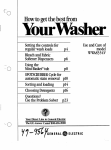
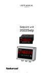
4YPICAL #ONFIGURATION -ENU 3EQUENCE
Shown below is a typical menu sequence for changing CO2 units from TORR to %.
1. Press SELECT (33) while turning the MULTINEX / Gas Module on.
2. Press left hidden key (7) to obtain Main Menu.
3. Press SELECT (33) until Display Parameter is displayed in reverse graphics.
ALARMS
TRACE 1
SIZE
MAIN MENU
TRACE 2
SIZE
Display Parameters
Select
Enter
CO2/SaO2 Output
SELECT
Audio Control
TRACE 3
SIZE
Exit
SELECT
4. Press ENTER (HI
(32)).
HI
LOW
AUTO
SET
Flow Rate Control
AUDIO
MUTE
SELECT
AUDIO
VOLUME
ALARMS
TRACE 1
SIZE
Display Parameters
TRACE 2
SIZE
CO2 Units
Select
Enter
Gas Trace Speed Default
SELECT
TRACE 3
SIZE
SELECT
SELECT
HI
LOW
Gas Trace Scale Default
AUTO
SET
Trend/Trace Partition Sekect
Trend Time Default
5. Press SELECT (33) and
choose CO2 Units.
6. Press ENTER (HI (32).
AUDIO
MUTE
Exit
AUDIO
VOLUME
ALARMS
TRACE 1
SIZE
Options
TRACE 2
SIZE
Torr
KPa
SELECT
%
TRACE 3
SIZE
Exit
Select
Enter
SELECT
7. Press SELECT (33) and
choose %.
HI
LOW
8. Press ENTER (HI (32)).
AUTO
SET
AUDIO
MUTE
SELECT
AUDIO
VOLUME
3-24
MULTINEX / Gas Module Operating Instructions
Chapter 3
#/3A/ /UTPUT #ONFIGURATION
This menu allows two selections:
• CO2 Only
• CO2/SaO2 Multiplexed
The output configuration refers to the CO2 analog output on pin 16 of the Datascope
Interface Connector (40).
When the CO2/SaO2 Multiplexed mode is selected, a pulse one tenth of a second long is
added to the CO2 waveform every 10 seconds. The height of the pulse shows the current
SaO2 value. Scaled at 1% SaO2 per mm., with a range of 60% to 100% SaO2.
)NTERFACING
The MULTINEX / Gas Module can interface with various equipment to provide the following
communication facilities to external devices:
• Analog outputs to compatible chart recorders
• Analog plethysmograph input from external oximeters
• Datascope Bus Connector for Datascope 2000RS (not applicable to Gas Module)
• Patient Data, Limits and Status to personal computers
7ITH $ATASCOPE !##53!4
An externally derived ACCUSAT plethsmograph can be displayed on the CRT of models
4300, 4100 Plus, Gas Module and 4100ID Plus.
1. Connect interface cable (0012-00-0547) between the MULTINEX / Gas Module rear
panel INTERFACE connector (40) and the interface connector on the rear panel of the
ACCUSAT.
2. Select PLETH on the MULTINEX / Gas Module.
NOTE: Models 4000ID Plus, 4000 Plus, and 4200 use an internal oximeter.
MULTINEX / Gas Module Operating Instructions
Chapter 3
3-25
)NTERFACING WITH THE OR ! -ONITOR
1. Connect the interface cable (0012-00-0547) between the MULTINEX rear panel
INTERFACE connector (40) and the interface connector on the rear panel of the 3000 or
3000A. See section 5.3 in the Operating Instructions for the procedure on how to mount
these units together.
2. When the 3000 Monitor is interfaced with Multinex Multi-Gas Monitor, the recorder will
annotate the monitored gases at the top edge of the strip chart recording. When CO2 is
selected as the source, an 11.5cm long recording strip of CO2 waveform (9.2 seconds for
12.5mm/sec, 115 seconds for 1mm/sec) is output along with time, date, and CO2 scale
annotated on the top edge of the recording.
3. When another source is selected (other than CO2), that source is recorded on a 52cm long
strip with the time, date, signal source specifics and scale on the top edge of the recording.
The full data stream is also printed: NIBP sys/map/dia, ET, SpO2, Resp Rate, FIO2, Insp
CO2, Exp CO2, Exp N2O, Insp N2O, Exp (Agent Name), Insp (Agent Name).
4. CO2 trend and Agent (generic) trend is available on screen display, whileCO2 (trace 3)
waveform option is NOT available. Recorder and Screen displays are independent.
3OFTWARE #OMPATIBILITY -ULTINEX 0LUS !
1. When interfacing a 3000 or 3000A with a Multinex Plus, (all other non-Plus, models are
fully compatible) the software revision of each monitor must be at or above the software
versions listed below. Incompatible software versions can result in improper agent labels
being annotated for DES and SEV.
3000A
3000
Multinex Plus
Datasette Revision D
Datasette Revision N
Datasette Revision Q
2. The 3000 software (Datasette) revision appears in the upper left corner of the LCD display
while in a service diagnostic screen, as "DS: (Rev Level)". Refer to the 3000 Service
Manual section 4.4.10 steps A-F for diagnostic screen access instructions.
3. The Multinex software (Datasette) revision is displayed in the lower left corner of the Service
Diagnostic Menu screen. Refer to the Multinex Plus Service Manual section 2.6 for screen
access instructions.
If necessary, software upgrades are available through Datascope. Contact the Datascope
Technical Support Department at 1-800-288-2121, for details.
3-26
MULTINEX / Gas Module Operating Instructions
Chapter 3
#ONNECTORS
The three interface connectors on the MULTINEX are, a 15-pin male sub-D connector, a
25-pin female sub-D connector, and a 24-pin female IEEE 488 style connector. Each pin
assignment is detailed below. Do not apply voltage to output pins as damage may occur.
Maximum non-destructive voltages are lised for each output pin.
15-pin Male Sub D (External Oximeter)
Voltage
Do Not Apply
Voltages >/=
RS-232C
RS-232C
RS-232C Limits
RS-232C Limits
0-1 V
0-1 V
+12.0 V
+12.0 V
0-1 V
0-1 V
0-1 V
0-1 V
0-1 V
+12.0 V
+12.0 V
+12.0 V
+12.0 V
+12.0 V
25-pin Female Sub D (PC Interface)
Voltage
Do Not Apply
Voltages >/=
1. Chassis Ground
2. TXD1 Transmit Data to external PC
3. RXD1 Receive Data to external PC
4. RTS1 Request to Send
5. CTS1 Clear to Send
6. N/C
7. Signal Ground
8. N/C
9. N/C
10. N/C
11. N/C
12. N/C
13. N/C
14. N/C
15. N/C
16. N/C
17. N/C
18. N/C
RS-232C
RS-232C
RS-232C
RS-232C
RS-232C
1. Chassis Ground
2. TXD3 Transmit Data to external oximeter
3. RXD3 Receive Data from external oximeter
4. N/C
5. N/C
6. N/C
7. Digital Reference
8. N/C
9. Respiration Rate analog output
10. Plethysmograph analog input from external oximeter equivalent to
0-100 % SaO2
11. CO2 Analog Output
12. N2O Analog Output
13. O2 Analog Output
14. Agent Analog Output
15. Analog Reference
MULTINEX / Gas Module Operating Instructions
Chapter 3
RS-232C Limits
RS-232C Limits
RS-232C Limits
RS-232C Limits
3-27
19. N/C
20. N/C
21. Plethysmograph Analog Output
22. % SaO2 Analog Output
23. Pulse Rate Analog Output
(4200, 4000 Plus & 4000ID Plus
only)
(4200, 4000 Plus & 4000ID Plus
only)
(4200, 4000 Plus & 4000ID Plus
only)
+12.0 V
+12.0 V
+12.0 V
24. N/C
25. Analog Reference
24-pin IEEE (Interface)
1. N/C
2. N/C
3. N/C
4. N/C
5. N/C
6. N/C
7. N/C
8. N/C
9. Digital Communications to 2000RS
10. N/C
11. N/C
12. Shield Ground
13. N/C
14. N/C
15. Control Line to 2000RS Motor
16. CO2/SAT Multiplexed Analog Output to
2000RS
17. N/C
18. N/C
19. N/C
20. N/C
21. Digital Reference
22. N/C
23. N/C
24. Analog Reference
3-28
Voltage
Do Not Apply
Voltages >/=
0 V, 5 V
+12.0 V
0 V, 5 V
0 - 1.2 V
+5.3 V
+14.0 V
MULTINEX / Gas Module Operating Instructions
Chapter 3
)NTERFACING TO 0ERSONAL #OMPUTERS
The MULTINEX / Gas Module allows users with properly equipped personal computers to
remotely access patient data, alarm limits and MULTINEX operational status over a wire
cable (not supplied). Personal computers must have RS232 serial communications capabilities
with the following characteristics:
• Format:ASCII
• Data Bits:8
• Stop Bits:1
• Parity Bit:None
• Baud Rate:2400
• Mark:-l0V
• Space:+l0V
Connection to the MULTINEX / Gas Module is done by wire cable connected to the 25-Pin
RS232 connector described in 3.20.2.
WARNING: Connection of non-insulated devices to the RS232 connector on this unit may cause chasis
leakage currents to exceed the specification standards. It is the user’s responsibility to ensure that leakage
currents do not exceed safe limits.
Refer to computer operator’s manual for specific wiring requirements.
Once properly connected and configured, the computer can request data by simple
commands. See Appendix for details on using the PC interface.
/04)/.!, 5.)4 #/.&)'52!4)/.3
5NITS %QUIPPED WITH 3A/
The additional features of the Model 4200 that are added to the basic unit are as follows:
1. The BEEP VOLUME key (14) is used to select the audible beep volume level. The default
setting for beep volume is LOW. If both the alarm and beep volume tones activate at the
same time, the alarm volume appears to be modulated on and off by the beep (at the
present volume).
Press BEEP VOLUME (14) to sound the beep at the present volume.
Press twice within 3 seconds to change the selected beep volume.
MULTINEX / Gas Module Operating Instructions
Chapter 3
3-29
2. A patient connector (17) for the oximeter probe.
3. A 2-digit, LED display (29) used to indicate SaO2 (0-99% SaO2 ).
4. A 3-digit, LED display (28) used to indicate pulse rate (30-250 beats per minute (bpm).
5. When either of the following messages appear above the CRT window associated with
PLETH, the SaO2 and Pulse Rate readings should not be used for patient management
purposes as the unit is not specified to work in these ranges.
"Pulse Rate <30"
"Pulse Rate >250"
6. The SaO2 warning tone will be present (see section 3.11).
5NITS %QUIPPED WITH !NESTHETIC !GENT
The additional features of the agent models that are added to the basic unit are:
1. A 2-digit, LED display (22) used to indicate End Tidal concentrations of the selected
agent (0-9.9%).
2. A 2-digit, LED display (20) used to indicate Inspired concentrations of the selected agent
(0-9.9%).
The display updates upon the completion of each breath. If new breath data is the same as
old breath data, the display flickers. Flickering indicates a new reading.
3. A momentary-action AGENT ID MODE key (7) is used to select the auto or verify mode
of operation for agent identification (4000ID Plus& 4100ID Plus only).
4. A momentary-action AGENT SELECT key (19) is used to indicate the selected anesthetic
agent (models 4000 Plus, 4100 Plus & Gas Module). This key also indicates the selected
anesthetic agent in the verify mode (models 4000ID Plus, 4100ID Plus).
Agent selections include Isoflurane, Halothane, and Enflurane. A red LED (21) indicates
which agent has been selected. The default setting is Isoflurane.
3-30
MULTINEX / Gas Module Operating Instructions
Chapter 3
3A/ 3ENSOR 3ELECTION
! )NTRODUCTION
A wide range of sensors are available for connection to the Datascope MULTINEX / Gas Module.
The sensors cover both short-term and long-term monitoring needs on patients ranging from
neonates to large adults.
The DATASENSOR is intended for short-term adult monitoring.
The FLEXISENSOR SD, available in five different sizes, provides both short-term and
long-term monitoring for large adults, adults, pediatrics, infants, and neonates. The
FLEXISENSOR SD is used when the DATASENSOR is not convenient or suitable.
The ear sensor is intended for long-term adult monitoring.
A range of disposable bandages are available for use with the FLEXISENSOR SDs. They are
available in 3 styles, SENSOR GUARD (used for large adults, adults and pediatrics), Coban
with SENSOR GUARD (used for infants) and LIGHTGUARD (used for neonates).
NOTE: Use only Datascope bandages with the Datascope FLEXISENSOR SDs.
Use of the sensors does not cause any penetration of the skin, nor is there any electrical
contact or transfer of excessive heat to the patient.
The sensor is composed of a light emitting diode (emitter) and a photodiode (detector). The
emitter discharges two colors (wave lengths) of light into the patient’s extremity (finger, toe,
ear). The detector receives that amount of light not absorbed by the blood or tissue
components. The MULTINEX / Gas Module then uses the relative absorption of the two
light wavelengths to compute and display SaO2 and Rate measurements.
The key benefits of the sensors are:
• Electrocautery Noise (ESU) Rejection
The sensor configuration of both the DATASENSOR and the FLEXISENSOR SD provide
uninterrupted monitoring and absence of false alarms during the use of ESU (ESU can be
set at any power level). This design prevents electro-surgical noise entering the monitor,
via the sensor, and interfering with unit operation.
• Monitoring Restless Patients
Motion artifact rejection is achieved in several ways.
1. The sensor design used with their recommended bandages assures a snug fit of the sensor
to the patient.
2. Light emitting diodes (LEDs) and detectors gather a strong signal from the patient.
MULTINEX / Gas Module Operating Instructions
Chapter 3
3-31
3. Software in the MULTINEX / Gas Module evaluates the shape of each pulse and
automatically rejects noisy and unreliable pulses.
4. When in the presence of motion, the software adjusts the "averaging-period", increasing it
to a maximum of 15 seconds during motion, and automatically reducing it during quiet
periods to obtain a fast response. This combination reduces the number of monitoring
interruptions and false alarms from patient motion.
• Tracking of Weak Peripheral Pulse Levels
Many patients suffer poor peripheral perfusion due to hypothermia, hypovolemia, reduced
cardiac output, etc. The MULTINEX is designed to automatically increase its gain to
track patients with poor peripheral perfusion.
• Rejection of Ambient Light
Many monitoring situations involve high levels of ambient light, i.e., operating room
lights, neonatal phototherapy, heat warmers, etc. The MULTINEX sensors, and bandages
each contribute to the rejection of ambient light. The monitor automatically measures and
corrects for high levels of ambient light. The enclosed design of the DATASENSOR
prohibits the interference of high levels of ambient light on adults with sensor operation.
And the opaque material used in the composition of the bandages, which are used with the
FLEXISENSOR SD, helps keep out ambient light.
• Patient Comfort
The FLEXISENSOR SD line is designed to work with a disposable bandage of three
styles (SENSOR GUARD, Coban and LIGHTGUARD) which conform comfortably
and safely to the particular patient’s anatomy.
• Can Be Re-sterilized (ETO sterilization - 3 times)
• Patient Isolation
• Ease of Application and Removal
3-32
MULTINEX / Gas Module Operating Instructions
Chapter 3
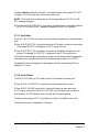
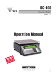
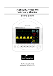
" 3ENSOR 3ELECTION AND !PPLICATION
Selection of a specific sensor is based on the patient’s size, physical condition, and expected
monitoring duration.
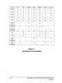
General guidelines for the selection of a sensor are provided in the Sensor Selection Table,
page 3-37.
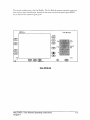
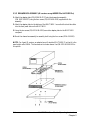
For optimal Datasensor and FLEXISENSOR® ensure that cable side is placed in the correct
position. See figures below.
Datasensor Placement
Flexisensor Placement
Detailed instructions for the application of a sensor to a patient are provided in each sensor
package.
# 3ENSOR #ONNECTION TO THE -5,4).%8
1. Align the cable connector on the sensor assembly with the SaO2 Connector (17) on the
MULTINEX.
2. Push the cable connector into the SaO2 Connector. Confirm that the cable
connector is securely in place.
NOTE: To obtain maximum cable use, do not twist the cable connector when
attaching to or disconnecting from the MULTINEX / Gas Module monitoring system.
MULTINEX / Gas Module Operating Instructions
Chapter 3
3-33
$ 3ENSOR )NSPECTION
Before use, always inspect sensors, cables, and connectors for damage, ie., cuts and abrasions.
Do not use the sensor, cable or connector if damaged. Replace with a good working sensor.
For long sensor life:
• Do not drop on the floor or give other sharp shocks to the sensor(s).
• Between use, store the sensors in the optional FLEXISENSOR SD Organizer, or coil the
sensor cable and store.
• Avoid running any cart, bed, or any piece of equipment over the sensor cable.
• Avoid strong pulls on the sensor cable (10 lbs/4kg).
• Watch for cracks in the DATASENSOR housing.
• Watch for cracks, cuts, rips, fogging, or signs of moisture in the FLEXISENSOR SD.
NOTE: For accessory part number information see Section 5.2, "Optional Accessories".
% 3ENSOR 0ERFORMANCE
For the BEST performance of all Datascope sensors:
• DO NOT PLACE any sensor on an extremity with an arterial catheter or blood pressure
cuff in place. Placement of an arterial catheter or blood pressure cuff on an extremity may
obstruct normal blood flow. False pulse rate information may result if the FLEXISENSOR
SD is placed on that same extremity. Place the sensor on the limb opposite the site of the
arterial catheter or blood pressure cuff.
• Encourage the patient to remain still. Patient motion may affect the sensor’s
performance. If it is not possible for the patient to remain still, replace the sensor bandage
on the FLEXISENSOR SD to assure good adhesion, or change the site of the
DATASENSOR.
• Check the DATASENSOR site every 2 hours and check the FLEXISENSOR SD site
every 8 hours on adults and every 4 hours on neonatal patients for indications of skin
abrasions, sensor displacement, sensor damage, or circulation impairment. Check the
sensor site every 4 hours if the ear clip is used. If necessary, remove and reapply the
sensor. If any of the above mentioned indications occur, immediately remove the sensor
and find an alternate site.
NOTE: Check the sensor site more frequently on infant and active patients.
3-34
MULTINEX / Gas Module Operating Instructions
Chapter 3
• Placement of the DATASENSOR may be difficult on patients with long fingernails or
artificial nails (over 1/4" long). Incorrect placement can also reduce the acquired sensor
signal, and therefore compromise performance. Select an alternate site (toe) or use a
FLEXISENSOR SD if the sensor can not be placed on the patient’s finger correctly or if
the fingernails interfere with the acquisition of a reliable signal.
• Use of the DATASENSOR is not recommended for long-term monitoring (4-6 hours).
Pressure from the spring mechanism on the DATASENSOR may cause minor skin
damage to the finger/toe used. For monitoring situations exceeding 4-6 hours, either
reposition the DATASENSOR every 2-4 hours to a different site (finger/toe) or use a
FLEXISENSOR SD with its appropriate bandage.
• Do not over-tighten the sensor bandages. Excessive pressure on the monitoring site can affect
SaO2 readings and may reduce readings below true SaO2. Excessive pressure can also result
in pressure necrosis and other skin damage.
• Sensor configuration provides uninterrupted monitoring in the following situations:
Electrocautery Noise - ESU rejection is designed into the sensors.
Motion Artifact - The monitor’s software adjusts the "averaging period" increasing it
during motion and reducing it during inactivity. This decreases the number of monitoring
interruptions and false alarms.
Weak Peripheral Pulses - The monitor’s gain is automatically increased to track pulses on
patients with decreased peripheral perfusion.
Sensors
Large
Adult
Adult (LA) (A)
Approximate
Patient Weight
Where Used
>80kg/
>176 lbs
Fingers,
Toes
Long or Short Term
Monitoring
ESIS
Reusable
Bandage Type
Pediatric
(P)
Infant
(I)
Neonate
(N)
Adult Ear Datasensor
(AE)
30 - 90kg/
10 - 40kg/
66 - 198 lbs 22 - 88 lbs
4.5 - 10kg/
10 - 22 lbs
Up to 5kg/
Up to 11 lbs
>40kg/
>88 lbs
Fingers,
Toes
Feet,
Palms, Big
Toes
Fingers,
Toes
40+ kg/
90+ lbs
Feet,
Adult Ear
Fingers,
Palms,
Toes
Heel,
Calf
Long &
Long &
Long &
Long &
Long &
Long &
Short Term
Short Term Short Term Short Term Short Term Short Term Short Term
Included
Included
Included
Included
Included
Included
Included
Yes Up to
20 Uses
Adhesive,
Disposable
Yes Up to
20 Uses
Adhesive,
Disposable
Yes Up to
20 Uses
Adhesive,
Disposable
Yes
6-Months
N/A
0998-000076-04
0683-000409-03
Yes Up to
20 Uses
NonAdhesive*,
Disposable
0998-000074-04
0683-000440
Yes Up to
20 Uses
N/A
0998-000076-05
0683-000409-02
Yes Up to
20 Uses
NonAdhesive*,
Disposable
0998-000074-03
0683-000415
0998-000074-05
N/A
0600-000026-xx
N/A
Part
Sensors 0998-000076-06
Numbers*
Bandages 0683-000409-01
SENSOR SELECTIONS
*See Accessories, Chapter 5, for more detailed information.
MULTINEX / Gas Module Operating Instructions
Chapter 3
3-35
0ERFORMANCE 6ERIFICATION
To ensure proper performance of the MULTINEX / Gas Module, a verification test should be
done by administering the MULTINEX Calibration Gas (Datascope Part Number
0683-00-0320) into the sample inlet and verifying performance to the specification. See the
figure below.
For safety reasons, the MULTINEX calibration gas contains Freon rather than one of the
three halogenated agents (Halothane, Enflorane, or Isoflorane). The ability of the
MULTINEX / Gas Module to directly measure Freon-22 was incorporated for calibration and
performance testing purposes.
Use the Freon mode (Test Mode) when verifying MULTINEX / Gas Module performance.
This test mode directly measures the contents of the MULTINEX cal gas.
Models with Agent Capability and ID Versions
1. Turn on the MULTINEX / Gas Module and wait 15 minutes for full warm-up.
2. Attach a sample catheter.
3. Press the ID Mode Key (7) to disable the ID function on units with Agent capability.
Press the Right Hidden Key (11) five times to enter the Freon Mode.
3-36
MULTINEX / Gas Module Operating Instructions
Chapter 3
The Freon ("TEST") mode is entered when all three agent selections are blank and Freon is
displayed above the agent trace.
4. Apply a steady stream of MULTINEX calibration gas.
The contents of the MULTINEX calibration gas is 60% N2O, 29% O2, 6% Freon-22,
and 5% CO2 (38 Torr). Verify that the MULTINEX / Gas Module numeric displays
reflect these values, plus or minus the specified accuracy, while in the Test Mode. See the
specifications in Chapter for the specified accuracy of each parameter.
5. For non-ID units, press the AGENT SELECT key (19) to exit the freon mode. For Agent
ID versions, press the "AGENT ID MODE" key (7) to return to normal operation.
MODELS 4200 and 4300
The MULTINEX Models 4200 and 4300 do not have a test mode for performance verification.
1. Turn on the MULTINEX and wait 15 minutes for full warm-up.
2. Attach a sample catheter.
3. After 15 minutes, press the "CAL" key (13) on the front panel.
4. When the "CAL IN PROGRESS" message disappears, apply a steady stream of
MULTINEX calibration gas into the sample catheter.
The contents of the MULTINEX calibration gas is 60% N2O, 29% O2, 6% Freon-22,
and 5% CO2 (38 Torr). Verify that the MULTINEX / Gas Module numeric displays
reflect these values, plus or minus the specified accuracy, while in the Test Mode. See the
specifications in Chapter 6 for the specified accuracy of each parameter.
MULTINEX / Gas Module Operating Instructions
Chapter 3
3-37
53%2 -!).4%.!.#%
This section of the manual outlines routine maintenance and general troubleshooting
guidelines.
The MULTINEX / Gas Module is designed for stable operation over long periods of time and
under normal circumstances should not require technical maintenance beyond that described
in this section. It is recommended that gas channel accuracy be checked once per year.
Contact qualified hospital personnel or Datascope for further information.
#ARE AND #LEANING OF -ONITOR
The instrument enclosure may be cleaned with a mild soap and water solution or ammoniated
window cleaner. DO NOT apply large amounts of liquid. DO NOT use abrasive cleaning
agents or organic solvents.
To prevent scratches on the front panel display screen, blow or carefully brush the dust and
dirt particles with a soft sponge or a fine, soft-haired brush. DO NOT use abrasives.
Fingerprints and stains may be removed by using a liquid lens cleaner and a soft cloth. DO
NOT wipe a dry screen or use alcohol or chlorinated hydrocarbon solvents.
2EPLACEABLE )TEMS
The following items are operator-replaceable:
• Catheters and Breathing Tube Adaptors
• O2 Cell
• Sump
• Scrubber Cartridge
• Software Cartridge
The replaceable O2 cell, sump, scrubber cartridge, catheters, breathing tube adaptors, and
external cables should be periodically inspected for signs of use or damage.
MULTINEX / Gas Module Operating Instructions
Chapter 4
4-1
#ATHETERS AND "REATHING 4UBE !DAPTORS
Replace the catheter and the endotrachial tube adaptor after each procedure. A package of 12
replacement catheters and breathing tube adaptors is available from Datascope Corp. and
authorized Datascope representatives. See Section 5.2, Optional Accessories.
Replacement
Prior to first use, sterilize the endotrachial tube adaptor by ETO sterilization, 12% ETO
140oF maximum.
NOTE: Use care when inspecting and storing these single-use items. The catheter and
endotrachial tube are fragile, Datascope can not assure that after first use, the catheters and
breathing tube adaptors will not deteriorate and therefore compromise MULTINEX / Gas
Module performance.
/ #ELL
Replace O2 cell when the O2 display shows "--" after initial power up O2 cal.
O2 cells are available from Datascope Corp. and authorized Datascope Representatives. See
Section 5.2, Optional Accessories.
Replacement can be made without opening the unit or making any internal or external
adjustments.
NOTE: Vent the new O2 cell for 24 hours prior to installation.
Replacement
1. Turn unit OFF.
2. Unplug the wire that protrudes from the rear panel to the O2 cell
3. Unscrew the O2 cell from the pneumatic connector.
4. Dispose the O2 cell and the rubber gasket in accordance with hospital procedure
5. Vent the new O2 cell for 24 hours prior to installation
6. Install a new rubber gasket and thread the new O2 cell onto the pneumatic connector.
7. Attach wire to the O2 cell.
8. Turn the unit ON. Observe the two minute O2 cell calibration.
4-2
MULTINEX / Gas Module Operating Instructions
Chapter 4
9. Verify that room air readings are 21%.
An O2 cell is required on the 4000ID Plus and 4100ID Plus models to achieve accurate CO2
readings.
3UMP
The disposable sump bottle can be cleaned or replaced at the conclusion of each monitor use
or when the sump fills. A package of 12 replacement sumps is available from Datascope
Corp. and from authorized Datascope Representatives. See Section 5.2, Optional Accessories.
Replacement
1. To remove, gently rotate the sump in a counter-clockwise direction.
2. Visually inspect the inside of the sump holder for liquid droplets and moisture. Dry with a
cotton swab if necessary.
3. Verify that the "O" ring seal remains inside the sump body.
4. Replace with a new sump. If a replacement is not available, clean the old sump in a soap
and water solution. DO NOT AUTOCLAVE. DO NOT GAS STERILIZE.
3CRUBBER #ARTRIDGE
Replace the scrubber cartridge, used on agent models when the cartridge turns a blue or
purple color or every 6 months. The date of first use should be written on the cartridge label
to determine when six months have elapsed. A package of 12 replacement cartridges is
available from Datascope Corp. and from authorized Datascope Representatives. See Section
5.2, Optional Accessories.
Replacement
1. Grasp the end of the cartridge and pull it straight out from the rear panel.
2. Write date of installation on label in area provided.
3. Push in the new cartridge until it reaches the stop.
NOTE: Failure to replace a depleted scrubber cartridge can result in large CO2 errors.
WARNING: Scrubber cartridge contains soda lime. Do not eat, breath in, or come in contact with
cartridge contents. Dispose of according to approved hospital procedure for soda lime. See Appendix,
Section 6.2, for the Material Safety Data sheets.
MULTINEX / Gas Module Operating Instructions
Chapter 4
4-3
3OFTWARE #ARTRIDGE
Replace the software cartridge anytime necessary.
Replacement
1. Disconnect power to the unit.
2. Unscrew the two retaining screws holding the top and bottom of the cartridge.
3. Use the handle and pull the cartridge straight out. Verify that the correct
Dattasette is being used with the unit.
4. Line up the new cartridge so the PROM chip is on the left side of unit.
5. Apply even pressure to the top and bottom of the cartridge and push it in until the metal
stop rests against the rear panel.
6. Tighten the two retaining screws to secure the cartridge.
7. Turn the MULTINEX / Gas Module ON. Verify basic operation by observing a successful
self test and by sampling a few breaths.
8. Return the old cartridge to Datascope Corp.
&USES
If replacement of a fuse is required, the unit should be referred to qualified service personnel,
as internal damage may be present. The correct fuse type and rating is shown below. Use only
the fuses supplied by Datascope Corp.
Line Voltage
90-132 V
198-264 V
4-4
Type
3AG
5 X 20 mm
Rating
T2.0A, 250 V
T1.0A, 250 V
Datascope P/N
0159-03-0015
0159-23-0001
MULTINEX / Gas Module Operating Instructions
Chapter 4
4ROUBLESHOOTING 'UIDELINES
This section contains messages that may appear on the screen to alert the user to take action.
Take the action indicated for Operator Response if any of the following messages should
display.
If service is required, contact a Datascope Service Representative. Internal servicing should
only be preformed by qualified personnel.
Chart 6 - Troubleshooting Guidelines
Message
Operator Response/Meaning
APNEA
No breaths detected during a
30-second period.
PURGING
No operator response needed;
unit clearing catheter obstruction.
OCCLUSION
Replace or clean catheter;
unit unable to clear catheter obstruction.
SUMP FULL
Sump bottle full; empty sump.
CAL IN PROGRESS
No operator response, normal operation;
unit performing auto-zero. It is normal
for the MULTINEX / Gas Module to
automatically recalibrate on a periodic basis.
FAN FAILURE
Fan has stopped rotating; turn unit off.
UNIT WARMING UP
Unit usable but not within specifications
(units with Agent capability only).
SYSTEM FAULT
CO2, N2O, Agent measurement system
self test unsuccessful. Power cycle the
monitor.
SO2 SENSOR OFF
Apply sensor to patient.
SO2 INTERFERENCE
Noisy signal due to patient motion or ESU.
PULSE LEVEL WEAK
Pulse signal detectable but not weak.
NO PULSE
Pulse not detactable.
MULTINEX / Gas Module Operating Instructions
Chapter 4
4-5
4-6
Message
Operator Response/Meaning
PULSE SEARCH
Temporary message while searching
for pulse.
CHECK SO2 SENSOR
Inadequate signal received by detector.
PULSE RATE <30
Pulse Rate detectable but less than
30 beats per minute.
PULSE RATE >250
Pulse Rate detectable but greater
than 250 beats per minute.
SaO2 UNCALIBRATED
SaO2 value displayed is below
specified accuracy rate.
SaO2 FAILURE
SaO2 self- test unsuccessful. Power
cycle the monitor.
DOWNLOADING
SaO2 program code being sent to
SaO2 PCBs.
FRONT PANEL KEY
BOARD IS NOT
CONNECTED
Power-up, self-test failure.
Unit needs service.
USER CONFIGURATION
ERROR-DEFAULT
CONFIGURATION
SELECT
The unit has detected an erroneous
change to the user configuration
and automatically selected a default
configuration.
FULL CALIBRATION
REQUIRED*
Power-up, self-test failure.
(Agent units with SaO2 only). Unit needs
to be recalibrated except for SaO2.
GAS MEASUREMENT
RESPONSE FAILURE*
Power-up, self-test failure
(units with Agent capability only)
GAS MEASUREMENT
SYSTEM SELF-TEST
FAILURE*
Power-up, self-test failure.
(units with Agent capability only)
READY
While in the agent auto ID mode,
unit is ready for agent identification
(units with Agent ID capability only).
MULTINEX / Gas Module Operating Instructions
Chapter 4
Message
Operator Response/Meaning
XXX WRONG AGENT
YYY
While in the confirmation mode,
indicates the agent detected, YYY,
does not agree with the agent
selected, XXX
(units with Agent ID capability only).
XXX AGENT ID DISABLED
Indicates agent ID is disabled and XXX is
the agent selected
(units with Agent ID capability only).
MIXED AGENTS
XXX, YYY
Indicates XXX agent is mixed with agent
YYY (units with Agent ID capability only).
NO ID: SELECT AGENT
Indicates agent ID is not working
(units with Agent ID capability only).
*For these messages the following message appears:
SELF TEST FAILURE-PRESS TRACE 1
TO CONTINUE
Operator query. Press Trace 1
SIZE to continue monitoring SaO2
If the only error is user configuration,
normal operation will begin with default
values.
MULTINEX / Gas Module Operating Instructions
Chapter 4
4-7
&REQUENT 052').' %VENTS DUE TO -OISTURE IN THE "REATHING
#IRCUIT ANDOR )MPROPERLY 3IZED !CCESSORIES
In the process of monitoring respiratory gases, moisture may appear in the sample line. This
moisture takes the form of either liquid or humidified gas coming from the patient circuit.
The Multinex / Gas Module incorporates a moisture elimination system that first separates
and then collects moisture typically found under normal conditions. This internal protection is
adequate to maintain the pneumatic integrity between preventive maintenance intervals.
When additional patient humidification requires using an external heated humidifier, consider
using combinations of external accessories as required. These accessories, hydrophobic filter
and Nafion tubing, are effective at limiting the excessive amount of liquid and humidity
that can overwhelm internal systems.
The hydrophobic filter (0378-00-0027) stops humidity and water from advancing into the
Multinex / Gas Module. This filter will occlude when saturated. For most economical and
effective use, place the external filter on the sample inlet (located on the front panel) of the
Multinex / Gas Module. Replace the filter when frequent "PURGING" messages begin to
appear. See the filter’s packaging information for complete usage instructions.
The external Nafion tubing (0008-00-0259) is an externally placed dehumidifying tube
that the patient sample passes through before entering the Multinex / Gas Module. Humidified
gas will be dehumidified to the ambient (outside) humidity level prior to it entering the
Multinex / Gas Module. This will allow the internal Nafion– tubing to liberate any remaining
humidity before advancing further inside the Multinex / Gas Module. For most economical
and effective use, place the Nafion– tubing between the sample line and the breathing circuit
connection. This will assure that the humidified patient sample is dehumidified before
condensing inside the length of the sample line.
Nafion– tubing begins to loose it’s properties when particles, accompanying the patient sample,
line the inner walls of the Nafion tubing. When the Nafion has reached the end of it’s
useful life, humidified patient sample is once again visible inside the sample tubing. See the
Nafion tubing’s packaging information for complete usage instructions. Using this device
results in fewer "PURGING" events.
A humidity trap is another device that controls the amount of humidity that enters the sample
line. This device is often referred to as a Heat/Moisture Exchanger (or HME). The HME
prevents the patient’s natural humidity and warmth from escaping into the breathing circuit
and sample line. The patient’s next inhalation delivers the previously exhaled moisture and
heat back to the patient’s lungs. Using this device results in fewer "PURGING" events.
Improperly sized sample lines also cause frequent "PURGING" events. The Multinex /
Gas Module is designed to use sample lines of a particular inner diameter and length. Smaller
tubing IDs or longer lengths will result in frequent "PURGING" events. Use Datascope
Sample Lines (0683-00-0405-XX) for best, and most reliable performance.
4-8
MULTINEX / Gas Module Operating Instructions
Chapter 4
Use appropriate accessories to reduce breathing circuit moisture, and install the Multinex
Preventive Maintenance Kit (0040-00-0128 or -0129) at regular intervals to reduce the
incidence of unscheduled service and the number of "PURGING" events.
MULTINEX / Gas Module Operating Instructions
Chapter 4
4-9
!##%33/2)%3
3TANDARD !CCESSORIES $OMESTIC AND %UROPEAN
DESCRIPTION
Standard Accessories Kit
1 Breathing Tube Adapter - Mask Elbow
1 Breathing Tube Adaptor - Straight Tee
1 Operating Instructions
1 Abbreviated Operating Instructions
1 Catheter Bore .050 dia., 10’ length
1 Catheter Bore .050 dia., 5’ length
Cable Assy., 3 CNDCT AC line 10’
Cable Assy., 3 CNDCT AC line 2.5 M
PART NUMBER
110 VAC
0020-00-0117-01
0683-00-0242-11
0683-00-0242-21
0070-00-0368
0070-00-0238
0683-00-0405-21
0683-00-0405-11
0012-25-0001
PART NUMBER
220 VAC
0020-00-0117-02
0683-00-0242-11
0683-00-0242-21
0070-00-0368
0070-00-0238
0683-00-0405-21
0683-00-0405-11
0012-25-0002
/PTIONAL !CCESSORIES
DESCRIPTION
O2 Cell
Interface Cable to 2000RS (5ft)
Package (12) Replacement Breathing Tube Adapters - Mask Elbow
Package (12) Replacement Breathing Tube Adapters - Straight Tee
PART NUMBER
0600-00-0002
0012-00-0271-02
0683-00-0242-12
0683-00-0242-22
Package (12) 10 ft. cat. .050 dia
Package (12) 5 ft. cat. .050 dia
0683-00-0405-22
0683-00-0405-12
Package (12) Replacement Sump Bottles (7.5ml)
Package (12) Replacement Sump Bottles (15ml)
Package (12) Replacement Sump Bottles (30ml)
Package (1) Replacement ACCUSORB Cartridges
0202-04-0001-12
0202-04-0002-12
0202-04-0003-12
0997-00-0222
Nasal Cannula (10 pieces)
Sample Cell (4200, 4300)
Sample Cell (4000ID, 4100ID, 4000ID Plus, 4100ID Plus)
Service Manual
0683-00-0424-10
0683-00-0420
0683-00-0419
0070-00-0250
MULTINEX / Gas Module Operating Instructions
Chapter 5
5-1
DESCRIPTION
PART NUMBER
MULTINEX Calibration Gas (Also used with Gas Module)
CO2 Calibration Gas
O2 Calibration Gas
N2O Calibration Gas
0683-00-0320
0683-00-0414
0683-00-0411
0683-00-0413
Gas Scavenging Adaptor Assy (19x19 tee
with hose and luer fitting)
Interface Cable to ACCUSAT
0997-00-0132
0012-00-0547
DATASENSOR w/3’ Cable
DATASENSOR w/12’ Cable
DATASENSOR Starter Kit
0600-00-0026-01
0600-00-0026-02
0020-00-0071-01
FLEXISENSOR S.D. Series with SENSOR GUARD Disposable Bandages:
Starter Kits: - Each kit includes one instrument cable, one FLEXISENSOR S.D. sensor and
(with the exception of the Adult Ear sensor) one package of SENSOR GUARD bandages
(24/pack LA, A, P; 12/pack I, N).
Large Adult (LA) non-sterile
Adult (A) non-sterile
Pediatric (P) non-sterile
Infant (I)
Neonate (N)
Adult Ear (AE)* non-sterile
0998-00-0094
0998-00-0093
0998-00-0092
0998-00-0083
0998-00-0090
0998-00-0091
FLEXISENSOR S.D. 3 Packs: - Contains 3 sensors of the same size.
Large Adult (LA) non-sterile
Adult (A) non-sterile
Pediatric (P) non-sterile
Infant (I)
Neonate (N)
Adult Ear (AE) non-sterile
Ear Clip
0998-00-0076-06
0998-00-0076-05
0998-00-0076-04
0998-00-0074-03
0998-00-0074-04
0998-00-0074-05
0380-00-0169
SENSOR GUARD Bandages:
Large Adult (LA) (3 packs of 24)
Adult (A) (3 packs of 24)
Pediatric (P) (3 packs of 24)
Infant (I) (36 bandages)
Neonatal Light Guard
0683-00-0409-01
0683-00-0409-02
0683-00-0409-03
0683-00-0415
0683-00-0440-03
* Adult Ear FLEXISENSOR is supplied with an ear clip and no bandage.
5-2
MULTINEX / Gas Module Operating Instructions
Chapter 5
DESCRIPTION
PART NUMBER
Instrument Cable
FLEXISENSOR S.D. Organizer
0012-00-0516-02
0683-00-0421
Cable Assembly, N200 Oximeter Interface
Cable Assembly, N100 Oximeter Interface
0012-00-0611
0012-00-0563
Fuse, 90-132V, 3GA, T2.0A, 250V
Fuse, 198-264V, 5x20mm, T1.0A, 250V
0159-03-0015
0159-23-0001
Preventive Maintenance Kits:
Kits include: O2 Cell, Nafion Tube, Sample Cell ACCUSORB Cartridge, Particle Filters,
and MULTINEX Cal Gas
4000ID, 4100ID, 4000ID Plus, 4100ID Plus
0040-00-0128
4200, 4300
0040-00-0129
MULTINEX / Gas Module Operating Instructions
Chapter 5
5-3
-OUNTING )NSTRUCTIONS
-5,4).%8 4/ 4(% ! -/.)4/2 ALL VERSIONS EXCEPT )$ 0LUS )$ 0LUS
1. Attach front stacking brackets (1) to the 3000A.
2. Align mounting tabs on brackets with mounting slots on the lower front panel of the
MULTINEX and slide into place.
3. Attach rear mounting brackets (2) to the back of the 3000A and fasten with screws (3).
Tabs on the brackets should be inserted into the rear of the MULTINEX.
PART NUMBER
MOUNTING KIT
Kit Includes:
Bracket, Stacking MULTINEX to 3000A Front
Bracket, Stacking MULTINEX to 3000A Rear
Bracket, Front Stacking
Bracket, Rear Stacking
Screw, Captive #4-40
Directions, Mounting
Instructions, MULTINEX to 3000A
5-4
QTY
0020-00-0058
0406-00-0479
0406-00-0478
0406-00-0451
0406-00-0477
0214-08-0001
0065-00-0060
0065-00-0061
2
2
2
2
4
1
1
MULTINEX / Gas Module Operating Instructions
Chapter 5
-5,4).%8 4/ /4(%2 5.)43
1. Select location for unit to be mounted onto the MULTINEX (left, center, right).
2. Fasten front stacking bracket (1) to the top of the MULTINEX.
3. Align the base of the peripheral unit with the mounting bracket and pull forward to lock
into place.
4. Attach rear mounting bracket (2) to the appropriate location and fasten with screw (3).
5. Lock peripheral unit into place. Unit should be unable to be rotated in any direction.
PART NUMBER
MOUNTING KIT
0020-00-0055
Kit Includes:
Bracket, Front Stacking
Bracket, Rear Stacking
Screw, Captive #4-40
Directions, Mounting
0406-00-0451
0406-00-0450
0214-08-0001
0065-00-0059
MULTINEX / Gas Module Operating Instructions
Chapter 5
QTY
3
3
3
1
5-5
$2!7%2 "/8 !33%-",9 ALL VERSIONS EXCEPT )$ 0LUS )$ 0LUS
1. Attach the adapter plate (P/N 0386-00-0137) onto the drawer box assembly
(P/N 0997-00-0257) using the four screws (P/N 0214-08-0003) supplied with the
assembly.
2. Attach the adapter plate to the bottom of the MULTINEX. Insure that the front tabs slide
into the front panel slots on the MULTINEX.
3. Using the two screws (P/N 0214-08-0002) secure the adapter plate to the MULTINEX
rear panel.
4. Mount the drawer box assembly to assembly shelf using the four screws (0214-08-0002).
NOTE: For Agent ID versions, an adapter box will raise the MULTINEX ID so that it is the
same height as the 3000A. This box does not include a drawer. Use P/N 0020-00-0061-02 for
this option.
5-6
MULTINEX / Gas Module Operating Instructions
Chapter 5
!00%.$)8
7ARRANTY
Datascope Corp. warrants that its products will be free from defect in workmanship and
materials for a period of one year from the date of purchase except that disposable or one-use
products are warranted to be free from defects in workmanship and materials up to a date one
year from the date of purchase, or the date of first use, whichever is sooner.
Datascope Corp. shall not be liable for any incidental, special, or consequential loss, damage
or expense directly or indirectly arising from the use of its products. Liability under this
warranty and the buyer’s exclusive remedy under this warranty, is limited to servicing or
replacing, at Datascope Corp’s option, at the factory or at an authorized Datascope Distributor any
product which shall under normal use and service appear to the Company to have been
defective in material or workmanship.
No agent, employee, or representative of Datascope Corp. has any authority to bind Datascope
Corp. to any affirmation, representation, or warranty concerning its products, and any
affirmation, representation, or warranty made by any agent, employee, or representative shall
not be enforceable by buyer.
This warranty is expressly in lieu of any other expressed or implied warranties, including any
implied warranty of merchantability or fitness, and of any other obligation on the part of the
seller.
Damage to any product or parts through misuse, neglect, accident or by affixing any nonstandard
accessory attachments, or by any customer modification voids this warranty. Datascope Corp.
makes no warranty whatever in regard to trade accessories, such being subject to the warranty
of their respective manufacturers.
A condition of this warranty is that this equipment or any accessories which are claimed to be
defective be returned when authorized by Datascope, freight prepaid to Datascope Corp.,
Paramus, New Jersey. Datascope Corp. shall not have any responsibility in the event of loss or
damage in transit.
The O2 Cells are warranted for six months, the SaO2 Datasensors are warranted for six
months, and the SaO2 Flexisensor SD’s are warranted for 30 days or first use, whichever
occurs first.
Accessory items such as Nafion, disk filters and sample cells are warranted for 90 days from
date of shipment.
The ACCUSORB cartridge is warranted for 30 days or first use, whichever occurs fits.
MULTINEX / Gas Module Operating Instructions
Chapter 6
6-1
%XTENDED 7ARRANTY
Datascope Corp. warrants that components within the monitor unit will be free from defects
in workmanship and materials for the number of years shown on the Datascope invoice. Under
this extended warranty, Datascope Corp. will repair or replace any defective component at no
charge for labor and/or materials. This extended warranty does not cover consumables such
as, but not limited to batteries, displays, external cables, sensors, the O2 cell, external tubing,
the sample cell, the sump or the Accusorb scrubber cartridge.
Recommended preventative maintenance, as prescribed in the service manual, is the
responsibility of the user, and is not covered by this warranty.
Except as otherwise provided herein, the terms, conditions and limitations of Datascope
Corp.’s standard warranty shall remain in effect.
6-2
MULTINEX / Gas Module Operating Instructions
Chapter 6
30%#)&)#!4)/.3
Dimensions:
4300, 4200
4100 Plus,
4000 Plus
Gas Module
4100ID Plus,
4000ID Plus
Height
6.5 in. (16.5 cm)
8.625in. (21.9cm)
Width
12 in. (30.5 cm)
12in. (30.5cm)
Length
19 in. (48.3 cm)
19in. (48.3cm)
Weight
25 lbs.
30 lbs.
Power Cord Length
10 ft.
10 ft.
Catheter
ft. (.050 "I.D.")
5 ft. (.050 "I.D.")
10 ft. (.050 "I.D.")
5 ft. (.050 "I.D.")
Power Requirements:
Voltage Input
90-132 VAC, 50/60 Hz,
198-264 VAC, 50/60 Hz
Maximum Leakage Current:
Chassis
less than 100 microamperes
Patient
less than 20 microamperes
Maximum Device SPL:
68 dBA (does not include audio output)
Power Consumption:
145 W maximum
MULTINEX / Gas Module Operating Instructions
Chapter 6
6-5
Analog Signal Specifications:
Output Impedance
120 ohms, max.
Output Stability
Compensation for capacitive loads up to
0.01 uF (5,000 ft of twisted pair cable)
Short Circuit Protection
At typical operating temperatures, output
can be shorted to ground indefinitely
Digital Signal Specifications:
Input Active Low
0.5 V max. at 1.0 mA
Input Active High
5.0 V + 1 V
Output Low Voltage
+ 0.5 V max. at 9 mA sink current
Output High Voltage
5.0 V +0 V, -1 V at 40 uA
%.6)2/.-%.4!, #(!2!#4%2)34)#3
Operating Temperature
10oC to 35oC*
Operating Humidity
85% max. non-condensing
Shock and Vibration
Meets ECRI (Dept. of Commerce
PB 296-892) Subclass B, device
Class 1 Environmental Test
Methods for Shock.
Shipping
Meets NTSA Test Procedure lA
(less than 100 lbs.)
Storage Temperature
-20o to +50oC**
*Operation between 25oC and 35oC for more than 5 continuous days may effect the life of
the O2 cell.
**Storage at 41oC to 50oC for more than 5 continuous days may effect the life of the O2 cell.
6-6
MULTINEX / Gas Module Operating Instructions
Chapter 6
Storage Humidity
0 to 85%, non-condensing.
Operating Altitude
Sea level -500 to 7,000 feet.*
Operating Attitude
Meets all stated performance
specifications while operating with
the rear feet on a rigid, flat surface.
Electrostatic Discharge
Susceptibility
CONFORMS TO IEC 801-2;
1991, Level 3 severity.
Electromagnetic Interference
Susceptibility
No malfunction occurs when the
device operates near any source
of EMI: including telemetry, radio
communications equipment, or electrosurgical devices where the field
strength and/or proximity to such
sources is a typical operating
environment for this type of device.
Tested per IEC 801-3.
Magnetic Interference
The unit produces less than 225
mGauss of magnetic interference when
and as measured 3/4" from any surface,
except the front. The front measures
</=1000 mGauss of magnetic interference.
Line Noise
The unit performs to the specifications
with +600 V random line interference.
(Recommended test instrument Berkley 3020 Line Noise Generator.)
Line Dropout
AC line dropouts of up to 40 ms every
10 s; will not interfere with system operation.
*Automatic calibration at desired altitude is assumed to achieve stated accuracy.
MULTINEX / Gas Module Operating Instructions
Chapter 6
6-7
0%2&/2-!.#% 30%#)&)#!4)/.3
NOTE: All performance specifications are achieved throughout the environmental operating
conditions listed in Section 1.3, Environmental Characteristics, and while observing the
following operational guidelines:
1. Allow 15 minutes for warm-up.
2. Calibrate the unit as instructed. See the calibration procedure in the MULTINEX / Gas
Module Service Manual, (0070-00-0250). (The calibration procedure should only be
performed by qualified service representatives.)
3. Use the specified breathing tube adaptor and I.D. catheter.
4. The maximum breath rate should not exceed 99 breaths per minute (bpm).
5. The flow rate is fixed by the microprocessor control at 150 mL/min. for the 4300/4200
and 200 mL/min for the 4100ID/4000ID. It may be user-adjusted for 50, 100, 150 or
200 mL/min.
NOTE: The Gas Module, 4000ID Plus, 4000 Plus, 4100ID Plus, and 4100 Plus models are
units with analytical agent capabilities while the 4200 and 4300 models are units without
analytical agent capability.
#/ $ISPLAY
Torr
%
KPa
Range
O - 76
0 - 9.9
O - 9.9
Resolution
1
0.1
0.1
Repeatability
(breath to breath)
+1
+ 0.1
+ 0.1
Rate
2 - 98 breaths per minute
6-8
MULTINEX / Gas Module Operating Instructions
Chapter 6
Accuracy (Torr)
Input Range
(Torr)
4200 / 4300
Gas Module / 4000 Plus
/ 4100 Plus / 4000IDPlus
/ 4100ID Plus
0 - 19.9
+ 1.5
+ 1.5
20 - 39.9
+ 2.0
+ 1.5
40 - 59.9
+ 2.5
+ 2.5
60 - 76.0
+ 3.0
+ 4.0
Models
NOISE
(peak to peak max)
4200 / 4300
Gas Module / 4000 Plus
/ 4100 Plus / 4000IDPlus
4100ID Plus
Torr
Torr
Torr
0-40
+0.2
+0.5
41-60
+0.2
+2.0
61-80
+0.2
+3.0
Drift (zero)
1 hour
24 hours
<0.5 Torr
or equivalent
<1.5 Torr
or equivalent
Response time to final reading models
4200, 4300
250 ms max at 150 cc/min flow
4000 Plus, 4100 Plus,
4000ID Plus, 4100ID Plus, Gas Module
250 ms max at 200 cc/min flow
Interference from
0 - 95% N20
+ 1 Torr (or equivalent %, KPA)
Interference from
0 - 100% H2O Saturated N2
<0.1%, relative.
MULTINEX / Gas Module Operating Instructions
Chapter 6
6-9
Interference from 5% to 95% O2
models
4200, 4300
+ 2 Torr
4000 Plus, 4100 Plus,
4000ID Plus, 4100ID Plus, Gas Module
compensated
Update
Upon 2nd breath completion
>5 Hz - before breath detection
Error due to breath rate
-.0015 of DC value x BPM
#/ !NALOG /UTPUT WAVEFORM
Range
0- lV
Scale Factors
0 - lV equivalent to 0 - 10%
Accuracy
+ 30 mV or + 5%, whichever is greater
Noise
<15mV p-p
Repeatability
+ 15mV
Interference from
0-95% N2O
+ 15mV
Interference from
0 - 100% H2O Saturated N2
+ 30mV
Interference from
5% CO2, 95% N2O
15 mV
Interference from
5% CO2, 95% O2
+ 30mV
6-10
MULTINEX / Gas Module Operating Instructions
Chapter 6
./ $ISPLAY
Range
0 - 99%
Resolution
1%
Rate
2 - 98 breaths per minute
Accuracy
Input Range (%)
Models
4200 / 4300
Gas Module /
4000ID Plus / 4100ID Plus
0-40
+3%
+2.5%
41-99
+5.0%
+6.0%
Repeatability
1%
Models
Noise
Drift (zero)
4200 / 4300
Gas Module /
4000 Plus / 4100 Plus
4000ID Plus / 4100ID Plus
+1%
+3%
1 hour(%)
24 hours(%)
2.0%
5.0%
Response time to final reading
4200, 4300
360 ms. max.
4000 Plus, 4100 Plus,
4000ID Plus, 4100ID Plus,
Gas Module
540 mx. max
Update
Synchronous with CO2 update.
Error due to breath rate
-.002 of DC value x BPM
MULTINEX / Gas Module Operating Instructions
Chapter 6
6-11
./ !NALOG /UTPUT WAVEFORM
Range
0 - 1.0V
Scale Factor
0 - 1.0V equivalent to 0 - 100%
Accuracy
+ 30 mV or + 5%, whichever is greater
Noise
15 mV p-p
Repeatability
+ 15 mV
/ $ISPLAY
Range
0 - 99%
Resolution
1%
Rate
2 - 98 breaths per minute
Accuracy
+ 3% absolute or 6% of reading,
whichever is greater
Noise
<0.5% of full scale
Repeatability
+ 1%
Interference from
0 - 100%, N2O combined with O2
<0.5% of full scale
Error due to breath rate
<0.005 of DC value x BPM, %O2
Response time (Step
change from 21% O2
to 100% O2
60 seconds to within 3 digits of
final reading.
Update
Synchronous with CO2
6-12
MULTINEX / Gas Module Operating Instructions
Chapter 6
/ !NALOG /UTPUT WAVEFORM
Range
0 - 1.0V
Scale Factor
0 - 1.0V equivalent to 0 - 100%
Accuracy
+ 30 mV or + 5%, whichever is greater
Noise
<15 mV pp
Repeatability
+ 15 mV
!NESTHETIC !GENT (ALOTHANE )SOFLOURANE %NFLURANE $ESFLURANE 3EVOFLURANE
A. Agent Display
Halothane
Enflurane
Isoflourane
Desflurane
Sevoflurane
Range
0-7%
0-7.5%
0-7.5%
0-20%
0-9%
Resolution
0.1%
0.1%
0.1%
0.1%(0-9.9%)
1%(10-20%)
0.1%
Rate
2-98
breaths/min
2-98
breaths/min
2-98
breaths/min
2-98
breaths/min
2-98
breaths/min
B. Accuracy (within 30 minutes of last cal)
Input Range (%)
Halothane
Enflurane
Isoflourane
Desflurane
Sevoflurane
0-5
±0.3%*
±0.2%
±0.2%
±0.2%
±0.2%
5 - max. value
±0.3%
±0.3%
±0.3%
±6% of value
±6% of value
Noise
±0.2%
±0.1%
±0.1%
±0.1%
±0.1%
*The Accuracy for Halothane is +0.3% for the first 60 minutes then goes to +0.2%.
MULTINEX / Gas Module Operating Instructions
Chapter 6
6-13
Halothane
Enflurane
Isoflourane
Desflurane
Sevoflorane
Response time to
final reading
500ms max
500ms max
500ms max
500ms max
500ms max
Update
Upon breath
completion
Upon breath
completion
Upon breath
completion
Upon breath
completion
Upon breath
completion
Repeatability
±0.1%
±0.1%
±0.1%
±0.1%
±0.1%
Drift
Included in above accuracy specifications.
C. Agent Identification - Models 4000ID Plus, 4100ID Plus
SOLITARY AGENT IDENTIFICATION
SENSITIVITY:
Halothane
Enflurane
Isoflourane
Minimum Concentration (@STP)
0.2%
0.2%
0.2%
Minimum single agent
detection time: (@STP)
15 seconds @ 200cc/min.
SECONDARY AGENT IDENTIFICATION (@STP)
THRESHOLD (after 15 minute warmup) 0.2%+5% of primary agent
Minimum secondary agent (@STP)
identification time:
30 seconds @ 200cc/min
!NESTHETIC !GENT !NALOG /UTPUT
(1 waveform for Agent selected for monitoring):
Range
0 - 1.0V
Scale Factor
0 - 1.0V equivalent to 0 - 10%
Accuracy
+ 30mV or + 5%, whichever is greater
Noise
<15mV p-p
Repeatability
+ 15mV
6-14
MULTINEX / Gas Module Operating Instructions
Chapter 6
2ESPIRATION 2ATE $ISPLAY
Range
2 - 98 breaths per minute
Resolution
1 breath per minute
Accuracy
+ 1 BPM or + 3% of reading, whichever
is greater with inspired/expired duty cycle
between 10% and 90%.
Update
Upon breath completion. Synchronous
with CO2.
2ESPIRATION 2ATE !NALOG /UTPUT $# LEVEL
Range
0 - 1.0V
Scale Factor
0 - 1.0 equivalent to 0 - 100 BPM
Accuracy
+ 10 mV or +3%, whichever is greater.
0LETHYSMOGRAPH !NALOG /UTPUT
Range
0 - 2.5V full scale output into 1K ohm
maximum load.
Scale
None
0LETH #24 $ISPLAY
Noise
1mm max.
MULTINEX / Gas Module Operating Instructions
Chapter 6
6-15
3A/ $ISPLAY
Range
0 - 99%
Resolution
1%
Update
Every 2 seconds
Accuracy (%)
270 - 100
60 - 69
0 - 59
<+2% SaO2 (1 S.D.)
<+4% SaO2 (1 S.D.)
Unspecified
Drift
none
Warm-up Time
15 sec.
Response Time to step change
of % SaO2 from 60 - 95%
(@ 72 bpm)
8 sec. to 95% of final value
3A/ !NALOG /UTPUT $# ,EVEL
Range
0 - 2.5V full scale output into 1k max. load
Resolution
40%/volt
Accuracy
+ 2% of full scale
0ULSE 2ATE $ISPLAY
Range
30 - 250 bpm
Resolution
1 bpm
Accuracy
+3 bpm or 3%, whichever is greater.
Update
Every 2 seconds
Response time to step change
of % SaO2 from 60 - 120 bpm
8 seconds to 95% of final value
6-16
MULTINEX / Gas Module Operating Instructions
Chapter 6
0ULSE 2ATE /UTPUT $# ,EVEL
Range
0 - 2.5 V full scale output into 1K max. load
Resolution
100 BPM/volt
Accuracy
+2% of full scale
!UDIO 3ETTINGS
Volume dBA SPL
High > / =72
Medium > / =64
Low > / =56
An internal non-volatile memory can be
set for a minimum alarm volume at OFF,
volume level 1
All recognized audio key depressions
generate a short tone at the low volume level.
3!&%49 #(!2!#4%2)34)#3
Risk currents per AAMI "Safe Current Limits for Electromedical Apparatus".
1. Source Current - Chassis
Less than 100uA measured from
chassis to ground through standard
AAMI load.
2. Source Current - Patient Circuit
(models 4000ID Plus, 4000 Plus and
4200)
Less than 10uA measured from
any lead of patient cable to
ground through standard AAMI
load at the connector or SaO2 sensor.
3. Sink Current - Patient Circuit
(models 4000ID Plus, 4000 Plus and
4200)
Less than 20uA measured from any
lead of patient cable to ground
through standard AAMI load in
series with 120K ohm resistance,
and isolated 120V/60 Hz voltage
at the connector or SaO2 sensor.
4. Isolation Voltage
1500V RMS at 60 Hz from any lead or
combination of patient leads to AC
hot or neutral for one minute.
5. Ground Resistance
Less than 0.1 ohm (110 volts) from
power connector U-blade to exposed
metal parts (0.2 ohm for 220V).
MULTINEX / Gas Module Operating Instructions
Chapter 6
6-17
3934%- #/-0!4)"),)49
All output signals (analog and digital) processed through the interface connectors, are
protected against short circuits to ground and can withstand normal static discharges as
detailed in Section 1.4, Performance Specifications.
The monitor, when connected to a 2000RS Recorder, provides a permanent record-keeping
of (not applicable for Gas Module):
• Inspired/Expired CO2 waveform recorded at 12.5 mm/s.
• Inspired/Expired CO2 real-time trend recorded at 1 or 5 mm/min.
• Inspired/Expired CO2 values in TORR.
• Inspired O2 values in percent.
• Breath Rate values in breaths/min.
• Inspired O2 values in percent
• Breath Rate values in breaths/min.
• SaO2 values in % SaO2
• Pulse Rate values in beats per minute.
The 2000RS Recorder prints all digital values on the chart border.
#/.&)'52!4)/.3
Model
#
Line
Voltage
(Vac)
Current
in
Amps
Frequency
(Hz)
Basic Features
Datascope
Part Number
4000ID Plus
90-132
1.6
50/60
CO2, N2O, Agent ID, SaO2
0998-00-0071-17
4000 Plus
90-132
1.6
50/60
CO2,N2O,O2,Agent,SaO2
0998-00-0071-13
4000ID Plus
198-264
0.8
50/60
CO2, N2O, Agent ID, SaO2
0998-00-0071-18
4000 Plus
198-264
0.8
50/60
CO2,N2O,O2,Agent,SaO2
0998-00-0071-14
4100ID Plus
90-132
1.6
50/60
CO2, N2O, O2, Agent ID
0998-00-0071-19
4100 Plus
90-132
1.6
50/60
CO2,N2O,O2,Agent
0998-00-0071-15
4100ID Plus
198-264
0.8
50/60
CO2, N2O, O2, Agent ID
0998-00-0071-20
4100Plus
198-264
0.8
50/60
CO 2,N2O,O2, Agent
0998-00-0071-16
4200
90-132
1.6
50/60
CO2,N2O,O2, SaO2
0998-00-0071-05
4200
198-264
0.8
50/60
CO2,N2O,O2,SaO2
0998-00-0071-06
4300
90-132
1.6
50/60
CO2,N2O,O2
0998-00-0071-07
4300
198-264
0.8
50/60
CO2,N2O,O2
0998-00-0071-08
Gas Module
90-132
1.6
50/60
CO2,N2O,O2,Agent
0998-00-0071-21
Gas Module
198-264
0.8
50/60
CO2, N2O,O2,Agent
0998-00-0071-22
6-18
MULTINEX / Gas Module Operating Instructions
Chapter 6
!'%.#9 #/-0,)!.#%3
The Datascope MULTINEX / Gas Module is designed to comply with the following agency
standards:
• CSA Standard C-22.2, No. 125
• LA County (UL 544 as a mandate)
• IEC 601-1 (on request for any model)
• VDE 871B (on request for any model)
• BS5724 (on request for any model)
Datascope maintains a policy of continual product improvement and reserves the right to
change materials and specifications without notice.
MULTINEX / Gas Module Operating Instructions
Chapter 6
6-19
#/ $ISPLAYS
Shown below are the optional display configurations available for the CO2 display. See
Section 3.21.1 for details on how to select the display configuration.
CO2 (TORR) Dry CO2 in TORR at sea level (760mmHg)
CO2 (%) Dry fractional CO2 in percent
CO2 (KPa) Dry CO2 in KPa at sea level (101.33 KPa)
CO2W (TORR) Wet CO2 in TORR at sea level (760mmHg)
CO2W (%) Wet fractional CO2 in percent
CO2W (KPa) Wet CO2 in KPa at local barometric pressure
PCO2 (TORR) Dry CO2 in TORR at local barometric pressure
PCO2 (KPA) Dry CO2 in KPa at local barometric pressure
PCO2W (TORR) Wet CO2 in TORR at local barometric pressure
PCO2W (KPa) Wet CO2 in KPa at local barometric pressure
6-20
MULTINEX / Gas Module Operating Instructions
Chapter 6
!NESTHETIC !GENT )DENTIFICATION
The MULTINEX 4000ID and 4100ID identify or confirm the presence of a single or
combination of vaporized anesthetic agents. Isoflurane, Enflurane or Halothane can be
identified by the MULTINEX.
Modes of Operation
A. Auto Identification Mode (Auto ID).
In this mode the MULTINEX identifies and measures any gas which is applied. When the
gas is changed by the anesthetist, the MULTINEX senses this and identifies the new gas. It
also qualifies the presence of a second agent of a lesser proportion, if present. The Auto ID
mode utilizes several CRT messages which advise the anesthetist of respiratory gas status. See
Section 4.3,
Troubleshooting Guidelines.
The MULTINEX ID will track agents above 0.2%. At the end of the case when the vaporizer
is off, the agent identified will remain for 30 minutes before the monitor displays READY.
B. Verify Mode
In this mode the anesthetist is required to select the anesthetic agent desired to be confirmed.
Once selected, the agent is confirmed and measured. If anesthetic agents are changed after the
initial selection, the new agent must be selected in order to continue monitoring (to be
confirmed). The confirmation mode utilizes several CRT messages which advise the
anesthetist of respiratory gas status. See Section 4.3, Troubleshooting Guidelines.
C. Manual Anesthetic Agent Selection (DISABLED mode)
This mode allows the unit to work with Sevoflurane and Desflurane, which can only be
selected manually. It also operates as the default mode in the event of a failed ID bench. The
MANUAL SELECT mode utilizes a single CRT message which alerts the anesthetist that the
MULTINEX is in the manual mode.
NOTE: Prior to applying des. or sev., select agent id disabled mode, then select agent.
Failure to do so will cause erroneous CO2, N2O and agent readings.
MULTINEX / Gas Module Operating Instructions
Chapter 6
6-21
Datascope Corp. 580 Winters Avenue, P.O. Box 5
Fax (201) 265-8562
Paramus, N.J. 07653-0005, U.S.A.
Tel. (201) 265-8800
Datascope B.V. DRS. V. van Royenstraat 8 3871 AN Hoevelaken P.O. Box 26 3870 CA Hoevelaken The Netherlands
Telephone 31-3495-44911 Fax 31-3495-34280
Printed in U.S.A.
0070-00-0368
REV A May 8, 1997