1
0291319
SE_A/RS
o:
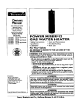
Gas Water Heater
Owners Manual
FOR POTABLE WATER HEATING
ONLY
NOT SUITABLE FOR SPACE HEATING
NOT FOR USE IN
MOBILE HOMES
MODEL
NUMBERS:
153.335200
153.335250
153.335251
153.335302
153.335350
153.335351
153.335400
153.335450
153.335451
153.335502
153.335550
153.335551
153.335600
153.335650
153.335651
153.335750
153.335751
153.335850
153.335851
153.335951
40
40
40
30
30
30
40
40
40
50
50
50
65
65
65
50
50
65
Gal.
Gal.
Gal.
Gal.
Gal.
Gal.
Gal.
Gal.
Gal.
Gal.
Gal.
Gal.
Gal.
Gal.
Gal.
Gal.
Gal.
Gal.
High Altitude
High Altitude
High Altitude
High Altitude
High Altitude
65 Gal.
40 Gal. L.P.
• Installation
• Operation
• Repair Parts
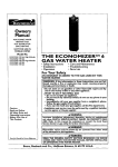
For Your Safety AN
ODORANT,S
ADDED
TOTHE
CAS
USED
BY THIS WATER
HEATER
WARNING:
If the information
in these
instructions are not followed exactly, a
fire or explosion may result, causing property damage, personal injury or dea]l_.
-Do not store or use gasoline or other
flammable
vapors affd liquids
in the
vicinity of this or any other appliance.
-WHAT TO DO IF YOU SMELL GAS
• Do not try to light any appliance.
• Do not to°uch any electrical switch; do
not use any phone in your building.
• Immediately
call your gas supplier
from a neigh_bor's phone. Follo'w the
gas supplierV's instrui:tions.
• if you can not reach your gas supplier,
call the fire department.
-Installation
and service must be performed by a qualified installer, service
agency or the gas supplier.
Save this Manual
for Future Reference.
k2
WARNING
Improper installation,
adjustment,
alteration, service or maintenance
can cause
DEATH, SERIOUS BODILY INJURY, OR
PROPERTY DAMAGE. Refer to this manual for assistance or consult the local Sears
Service Center or gas utility for further
information.
WARNING
0
Flammable vapors may be drawn by air
currents from other areas of the structure to this appliance.
WARNING
READ THE GENERAL SAFETY SECTION
BEGINNING
ON INSIDE COVER AND
THEN THIS ENTIRE MANUAL
BEFORE
INSTALLING
OR OPERATING
THIS
WATER HEATER.
Z
WARNING
Improper installation, adjustment, alteration, service or maintenance can cause DEATH, SERIOUS BODILY INJURY OR PROPERTY DAMAGE. Refer to this manual for assistanceor consult
your local Sears Service Center for further information.
WARNING
At the time of manufacture thiswater heater was provided with a
combination temperature-pressures relief valve certified by a
nationally recognized testing laboratory that maintains periodic
inspedion of produdion of listed equipment or materials,as meeting the requirements for Relief Valvesand Automatic Gas Shutoff
Devices for Hot Water Supply Systems,and the latest edition of
ANSI Z21.22 and the code requirementsof ASME. If replaced, the
valve must meet the requirementsof local codes,but not lessthan
a combination temperature and pressure relief valve certified as
meeting the requirements for Relief Valves and Automatic Gas
Shutoff Devices for Hot Water Supply Systems,ANSI Z21.22 by a
nationally recognized testing laboratory that maintains periodic
inspectionof produdion of listedequipment or materials. _
The valve must be marked with amaximum set pressurenot to
exceed the marked hydrostatic working pressure of the water
heater (150 Ibs:q./s in.) and a dischargecapacity not less.than the
water heater input rate as shown on the model rating plate.
(Electric heaters- watts divided by 1000 x 3415 equal BTU/Hr.
rate.)
Your local jurisdictional authority, while mandating the use of a
temperature-pressurerelief valve complyingwith ANSI Z21.22 and
ASME,may require a valve model different from the one furnished
with the waterheater.
Compliance with such local requirementsmust be satisfiedby-the
installer or end user of the water heater with a locally prescribed
temperature-pressurerelief valve installedin the designatedopening in the water heater in placeof the factory furnishedvalve.
For safe operation of the water heater,the relief valve must not be
removedfrom it's designatedopening or plugged.
The temperature-pressure reh'ef valve must be installed directly
into the fitting of the water heater designatedfor the relief valve.
Position the valve downward and provide tubing so that any discharge will exit only within 6 in(_hesabove, or at any distance
below the structural"floor.Be certain that no contact is made with
any live electrical part. The dischargeopening must not be blocked
or reduced in sizeunder any circumstances.Excessivelength, over
15 feet, or use of more than two elbows can causerestridion and
reduce the dischargecapacity of the valve.
No valve or other"obst'ructionis to be placed between the relief
valve and the tank. Do not connect tubing directly to discharge
drain unlessa 6" air gap is provided. To prevent bodily injury, haz'
....
a r d to life,
or property-damage,the
relief valve must be allowed to
dischargewater in quantitiesshould circumstancesdemand. If the
discharge pipe is not connected to a drain or other suitable
means, the water flow may causeproperty damage.
The Discharge Pipe:
--Must not Me smaller in size than the outlet pipe size of the
valve, or have any reducing couplings or other restridions.
--Must not be plugged or blocked.
--Must be of material listed for hot water distribution.
--Must be installed so as to allow complete drainage of both
the temperature-pressure relief valve, and the discl_argepipe.
--Must terminate at an adequate drain.
--Must not have any valve between the relief valve and tank.
WARNING
A fire can start if combustible materials such as clothing, cleaning
materials, or flammable liquids are placed against or next to the
water heater.
WARNING
WATER HEATERSEQUIPPED FOR ONE TYPE GAS ONLY: This
water heater is quipped for one type gas only. Check the model
ratingplate near the gascontrol valve for the corred Eas.DO NOT
USE"IHIS WATERHEATERWITH ANY GAS OTHEI_ THAN THE
ONE SHOWN ON THE MODEL RATING PLATE.Failureto usethe
corred gas can causeproblemswhich can result in DEATH, SERIOUS BODILY INJURY,OR PROPERTYDAMAGE. If you have any
questionsor doubtsconsultyourgassupplieror localutility.
WARNING
INSTALLATIONS IN AREAS WHERE FLAMMABLE LIQUIDS
(VAPORS) ARE LIKELYTO BE PRESENTOR STORED(GARAGES,
STORAGE,AND UTILITY AREAS,ETC):Flammableliquids(suchas
gasoline,solvents,propane (LP) or butane, etc.), all of which emit
flammable vapors, may be improperly stored or used in such
areas. The gas water heater pilot light or main burner can ignite
such vapors.The resultingflashback and fire can causedeath or
seriousburnsto anyone in the area, as well as pro_rty damage.
If installationin suchareas is your only option, then the installation must be accomplishedin a way that the pilot flame and main
burner flame are elevated from the floor at least 18 inches.While
thismay reducethe changesof flammable vaporsfrom a floor spill
being ignited, gasoline and other flammable substancesshould
never I_ storedor usedin the same room or area containinga gas
water heater or other open flame or sparkproducingappliance.
NOTE: Flammable vapors may be drawn by air (_urrentsfrom
other areasof the structureto the appliance.
WARNING
HOTTER WATERCAN SCALD:Water heatersare intendedto produce hot water. Water heated to a temperaturewhich will satisfy
clothes washing, dish washing, and other sanitizing needs can
scald and permanentlyinjure you upon contact. Some people are
more likely to be permanently injured by hot water than others.
These include the elderly, children, the infirm, or physically/mentally handicapped.If anyoneusinghot water in your home fits into
one of thesegroupsor if there is a local code or statelaw requiring a certain temperature water at the hot water tap, then you
must take specialprecautions.In addition to usingthe lowest possibletemperaturesettingthat satisfiesyour hot water needs,some
type of tempering device, such as a mixing valve, shouldhe used
at the hot water taps usedby thesepeople or at the water heater.
Mixing valvesare availableat plumbing supplyor hardwarestores.
Follow manufacturersinstructions for installation of the valves.
Before changing the factory setting on the thermostat, read the
"Temperature Regulation"sectionin this manual.
WARNING
BEFORELIGHTING [PROPANE (L.P.) GAS WATER HEATERS]:
Propane(LP.) gasis heavier than air. Should there be a leak in the
system, the gas will settle near the ground. Basements,crawl
spaces,skirtedareas under mobile homes(even when ventilated),
closetsand areasbelow ground level will serve aspocketsfor the
accumulationof this g as, Before
attempting
to light
or. relight• the
•
---_
water heater'spilot or turning on a nearby electrical light switch,
be absolutelysure there is no accumulated gasin the area. Search
for odor of gas by sniffing at _round level in the vicinity of the
appliance. If odor is detected, _'ollow stepsindicated at "For Your
Safety"on the coverpage of thismanual then leave the premises.
WARNING
Do not use this appliance if any part of it hasbeen under water.
Immediately call a SearsService Technicianto inspectthe appli.
ance and to replace the gas control or any part of the burner system which hasbeen underwater.
WARNING
;This water heater must not be installed directly on carpeting.
Carpetin.gmust be protected by a metal or woodpanel beneath
the appliance extending b.eyondthe full width and depth of the
appliance by at least 3 inches (76.2mm) in any direction, or if the
appliance !s installed inan a!coveor closet,the entire floor must
be covered by the panel. Failure to heed this warning may result
in a fire hazard.
WARNING
A gas water heater cannot operate properly without the correct
amount of air for combustion. Do not install in a confined area
such a closet, unlessyou provide air as shown in the "Locating
The New Water Heater" section. Never obstruct the flow of ventilation air. If you have any doubts or questionsat all, call your
gas company. Failure toprovide the proper amount of combustion air can result in a fire or explosion and can cause DEATH,
. SERIOUS BODILY INJURY, OR PROPERTYDAMAGE.
WARNING
If this water heater will be used in beauty shops,barber shops,
cleaning establishments,or self-servicelaundrieswith dry clean"ing equlpment, it is imperative that the water heater or water
heaters be installed so that combustion and ventilation air be
taken from outside these areas. Refer to the "Locating The New
Water Heater" section of thismanual and alsothe latest edition of
the National Fuel Gas Code, ANSI Z223.1, also referred to as
NFPA 54 for specificsprovided concerning air required.
WARNING
_VENTDAMPERS- Any vent damper, whether it is operated thermally or otherwise must be removed if its use inhibits proper
drafting of the water heater.
Thermally Operated Vent Dampers: Gas-fired water heaters having thermal efficiency in excessof 80% may producea relatively
low flue gas temperature. Such temperatures may not be high
enough to properly open thermally operated vent dampers. This
would causespillage of flue gasesandmay causecarbon monox'ide poisoning.
Vent dampers must bear evidence of certification as complying
with the latest edition of American National Standard ANSI
Z21.68 (ANSI Z21.66 & 67, respectively, cover electrically and
mechanically actuated vent dampers). Before installationof any
vent damper, consult your local SearsService Center or the gas
utility for further information.
WARNING
1. The appliance and its individual shutoff valve must be disconnected from the gassupply piping systemduring any pressure
testingof the gas systemat test pressuresin excessof '/2pound
per square inch (3.5kPa).
2. The appliance must be isolatedfrom the gassupplypiping system by closin.gits individual manual..shutoffvarve during any
pressure testing of the gas supply piping systemat test pressuresequal or lessthan _2pound per squareinch (3.5kPa).
WARNING
_!Soot build-up indicates a problem that requirescorrection before
further use. Turn "OFF" gas to water heater and leave "OFF"
until repairs are made, becausefailure to correct the causeof the
Sooting can result in a fire or explosion causing DEATH, SERIOUS BODILY INJURY,OR PROPERTYDAMAGE.
WARNING
The water heater with draft hood installed must be properly
vented to a chimney which terminates outdoors. Never operate
the water heater unlessit is vented to the outdoors and has adequate air supply to avoid risksof improper operation, explosion
or asphyxiateon.
WARNING
Obstructed or deteriorated vent systems may present a serious
health riskor asphyxiation.
WARNING
Chemical vapor corrosion of the flue and vent systemmay occur
if air for combustioncontains certain chemical val_rs. Spraycan
propellants, cleaning solvents, refrigerator and air conditioner
refrigerants, swimming pool chem|cals, calcium and sodium
chloride, waxes, bleach, and processchemicalsare typical compoundswhich are potentially corrosive.
WARNING
Minimum clearancesbetween the water heater and combustible
constructionare 1" at the sidesand rear, 4" at the front, and 6"
from the vent pipe. Clearance from the top of the jacket is 18"
on most models. Note that a lesser dimension may be a!lowed
on some models.Refer to the label on the water heater adjacent
to the gascontrol valve for all clearances.
WARNING
HYDROGEN GAS: Hydrogengascan be producedin a hot water
systemthat hasnot been usedfor a long period of time (generally two weeks or more). Hydrogen gas ts
_ extremely flammable
and explosive. To prevent the poss_ility of injury under these
conditions, we recommendthe hot water faucetbe opened for
several minutes at the kitchen sink before any electrfcal appliances which are connected to the hot water system are used
(such as a dishwasher or washing machine). If hydrogen gas is
present, there will probably be an unusualsoundsim]lar to a!r
escaping through the pipe as the hot water faucet is opened.
There must be no smokingor open flame near the faucet at the
time it is open.
WARNING
INSULATING JACKETS:When installing an external water heater
insulationjacket on a gas water heater:
a. DO NOT cover the temperature-pressurerelief valve.
b. DO NOT put insulationover any part of the top of the gas
water heater.
c. DO NOT put insulation over the gas control valve or gas control valve/burner cover,or any accessareas to the burner.
d. DO NOT let insulation around the gas water heater to get
within 8 inchesof the floor (air must get to the burner).
e. DO NOT cover or remove operating instructions, and safety
related warning labels and materials affixed to the water
heater.
Failure to heed this will result in the possibility of a fire or
explosion.
WARNING
Do not usethis appliance if any part of it has been under water.
Immediately call a SearsServiceTechmclan to inspect the appliance andto replace the gascontrol or any part of the burner system which hasbeen underwater.
CAUTION
WATER HEATERSEVENTUALLYLEAK: Installation of the water
heater must be accomplishedin such a manner that if the tank or
any connections should leak, the flow of water will not cause
damageto the structure. When such locations cannot be avoid.
ed, a suitable drain pan should be installed under the water
heater. Drain pansare available at your local Searsstore, Sucha
drain pan must be not greater than 11/_inches deepthave a minimum length andwidth of at least 2 inchesgreater than the water
heater dimensionsand must be .piped to an adequate drain. The
pan must not restrict combust,on air flow. Under no circumstances is the manufacturer or Sears to be held liable for any
water damagein connectionwith this water heater.
General Safety....................................................................................
_-_
Table of Contents ...............................................
............................................................
................
4
Introduction .............
...........................................................................................
5
SPepeCifica
tions ..........................................................................................
........
5
aring for the New Installation ................................................
...._
.................
s
Materiafs and Basic Tools Needed .............
_.............
_...................................
,........
6
Materials Needed ..................................................................................................................................................
Basic Tools ............................................................................................................................................................
6
6
Removing the Old Water Heater. ............................................................
7
Locating the New Water Heater .............................................................
8-9
Facts to Consider About Location ..........................................................................................................................
Combustion Air and Ventilation for Appliances Located in Unconfined Spaces .....................................................
Combustion Air and Ventilation for Appliances Located in Confined Spaces .........................................................
8
9
9
Installing the New Water Heater .............
,...................................................
lo-14
Water Piping ..........................................................................................................
..............................................
Temperature-Pressure Relief Valve .......................................................................................................................
Filling the Water Heater..: ....................................................................................................................................
Venting ................................................................................................................................................................
Gas Piping ...................................................................................................................................................
•........
Installation Checklist ...........................................................................................................................................
10
11
12
12
13
14
Lighting ...........................................................................................................
_s-_6
Temperature Regulation ............................................................................
lz
For Your Information .......
.............................................................................
;_a-19
Start Up Conditions ... ..........................................................................................................................................
I8
Condensation ....................................................................................................................................
"................ 18
Smoke/Odor ......................................................................................................................................................
18
Thermal Expansion .............................................................................................................................................
18
Strange Sounds ..................................................................................................................................................
18
Operational Conditions .........................
. .................... ....................................................................................
18-19
Smelly Water .....................................
_..........................................................................................................
18-19
"Air" In Hot Water Faucets ................................................................................................................................
19
High Temperature Shut Off System ....................................................................................................................
19
Not Enough or No Hot Water ............................................................................................................................
19
Water Is Too Hot ...........................
i ....................................................................
................................................
19
Periodic Maintenance
.................................................................................
2o-2_
Venting System Inspection ...................................................................................................................................
Burner Inspection ................................................................................................................................................
Burner Cleaning ..................................................................................................................................................
Propane (L.P.) Gas Control Valve & Burner Assembly Replacement Information ..................................................
Housekeeping ...........................................................................................................
. .........................................
Temperature-Pressure Relief Valve Operation ......................................................................................................
Tank Sediment Cleaning ................. •.....................................................................................................................
Draining ..............................................................................................................................................................
Drain Valve Washer Replacement ..............................................................................
_.........................................
Service ................................................................................................................................................................
20
20
20
20
20
21
21
21
21
21
F
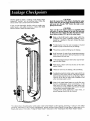
Leakage Checkpoints ..............................................................................
22
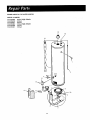
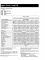
Repair Parts .............................................................................................
.................................. 24-31
IAI
._L..
vvarramv .....
................................................................................................
32
About Your
"!warranty
.............. .................................
,...........................................................................................
Sears Installation Policy .......................................................................................................................................
Sears Installation Warranty ...................................................................
.'..............................................................
32
32
32
WARNING
-""/hanK You
for purchasing a Sears water heater.
_roDerly installed and maintained, it should give you years of
rouble free service. If you should decide that you want the new
rater heater professionally installed by Sears call the local Sears
;ervice Center or any Sears store. They will arrange for prompt,
luality installation by Sears authorized contractors.
_bbreviations Found In This Instruction
Manual
A.G.A. - American Gas Association
,.N.S.I. - American National Standards Institute
J.F.P.A. - National Fire Prevention Association
This gas-fired water heater is design certified by the
American
Gas Association
Laboratories
under
American National Standards for Gas Water Heaters.
The installation
must conform with this manual, Local
Codes and with the latest edition of the National Fuel
Gas Code, ANSI Z223.1.
This publication is available from your local government or public library, gas company, or by writing
NFPA, Batterymarch Park, Quincy, MA 02269.
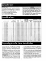
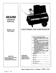
RECOVERY
MODEL
NUMBER
153.335200
153.335250
CAPACITY
TANK
IN GALLONS
40
40
OF
TYPE
GAS
NATURAL
NATURAL
153.335251
153.335302
40
30
153.335350
153.335351
DIMENSIONS
B.T.U.
RATE
35,000
35 O00
PER HOUR
I _._l_- tJAL_.
@ 90°F RISE
35.8
35.8
NATURAL
NATURAL
35,000
40,000
35.8
40.9
3" or 4"
3" or 4"
20"
- 16"
471/2''
57'/2"
30
30
NATURAL
NATURAL
40,000
40.000
40.9
40.9
3" or 4"
3" or 4"
16"
16"
57'/2"
57'/,."
153.335400
153.335450
153.335451
153.335502
40
40
40
50
NATURAL
NATURAL
NATURAL
NATURAL
40,000
40,000
40,000
40,000
40.9
40.9
40.9
40.9
3"
3"
3"
3"
4"
4"
4"
4"
18"
18"
18"
20 'I
58'/4"
581/4''
58'/4"
58"
153.335550
153.335551
153.335600
50
50
65
NATURAL
NATURAL
NATURAL
40,000
40,000
40,000
40.9
40.9
40.9
3" or 4"
3" or 4"
3" or 4"
20"
20"
22"
,,
58"
58"
59'/2"
....
153.335650
153.335651
65
65
NATURAL
NATURAL
40,000
40,000
40.9
40.9
3" or 4"
3I' or 4"
22"
"22"
59'/2"
591/2''
153.335750
153.335751
153.335850
153.335851
153.335951
50
50
65
65
40
NATURAL
NATURAL
NATURAL
NATURAL
PROPANE
52,500
52,500
50,000
50,000
40,000
53.7
53.7
51.2
51.2
40.9
4"
4"
4"
4"
3" or 4"
20"
20"
22"
22"
18"
583/4''
58¥4"
591/2'i
591/2"
",58'/4"
I
VENT
MINIMUM
PIPE
3" or 4 'I
3" or 4"
IN INCHES
or
or
or
or
....
Readthe "GeneralSafety"section,pages2 and 3 of this manual
first and then the entiremanualcarefully.If you don't follow the
safetyrules,the water heaterwill not operateproperly. It could
causeDEATH,SERIOUSBODILYINJURYAND/OR PROPERTY
DAMAGE.
This manualcontainsinstructionsfor the installation,operation,
and maintenanceof the gas-firedwater heater.It also contains
warnings through out the manual that ou must read and be
awareof. All warnings
Y
and all instructionsare
essentialto the
properoperationof the water heaterand your safety.Sincewe
cannotput everythingon the first few pages,READTHE ENTIRE
MANUAL BEFOREATTEMPTINGTO INSTALLOR OPERATE
THEWATER
HEATER.
Theinstallationmustconformwith the instructionsin this manual;
gascompanyrules;and LocalCodes,or in the absenceof Local
Codes,with the latestedition of the NationalFuelGascode,ANSI
Z223.1,also referredto as NFPA54. This publication is available
HEIGHT TO
DIAMETER JACKET TOP
20" .....
47'/2"
20"
47'/2"
,
.
,
"'
[
from yourlocal governmentor public library or gascompanyor
bywriting NFPA,BatterymarchPark,Quincy,MA 02269.
3. If after reading this manual you have any questionsor do not
understandany portionof the instructions,call the SearsService
Center.
4. Carefully plan the place where you are going to put the water
heater.Correctcombustion,vent action,andvent pipe installation
are very important in preventing death from possible carbon
monoxidepoisoningand fires.
Examinethe locationto ensurethewaterheatercomplieswith the
"Locatingthe NewWaterHeater' sectionin thismanual.
5. For California installation this water heater must be braced,
anchored,or strappedto avoid falling or movingduringan earthquake. See instructions for correct installation procedures.
Instructionsmay be obtainedfrom your local dealer, wholesaler,
public utilities or California Office of the StateArchitect,400 P
Street,Sacramento,
CA 95814.
Materials Needed
WM_
To simplify the installation Sears has available the installation parts shown below. You may or may not need all of
these materials, depending on your type of installation.
:
i
WATER HEATER STAND 24"x24"x18"
FOR USE WITH WATER HEATERS INSTALLED
IN RESIDENTIAL
GARAGES HAVING A DIAMETER 24" OR LESS AND A RATED CAPACITY
75 GALLONS OR LESS
i
COMPRESSION COUPLINGS
FOR CONNECTING TO
COPPER PLUMBING WITHOUT SWEAT SOLDERING
EXPANSION
TANKS FOR
THERMAL EXPANSION
CONDITIONS
AVAILABLE
IN 2 GALLON AND 5
GALLON CAPACITY
THROUGH
LOCAL SEARS
SERVICE CENTERES
VENT ELBOW
FLEXIBLE WATER
HEATER GAS CONNECTOR WITH
FITTINGS
Wi_
Heat
P,4attr
Tr_$
i
WATER HEATER
INSTALLATION
KIT WITH
FLEXIBLE CONNECTORS
FOR
3/4" GALVANIZED
OR
1/2"COPPER PLUMBING
VENT EXTENSION
WATER HEATER HEAT TRAPS
HELP REDUCE HEAT LOSS DUE
TO THERMAL SYPHONING
DRAIN PANS
AVAILABLE IN 20" DIAMETER FOR
WATER HEATERS HAVING
A DIAMETER 18"
OR LESS AND AVAILABLE IN 28" DIAMETER
FOR WATER HEATERS HAVING A DIAMETER
26" OR LESS
Basic Tools
You may or may not need all of these tools, depending on
your type of installation. These tools can be purchased at
your local Sears store.
Pipe Wrenches (2) 14"
Screwdriver
Tin Snips
6 Foot Tape of Folding Rule
Garden Hose
Drill
ADDITIONAL
TOOLS NEEDED
WHEN SWEAT SOLDERING
Tubing Cutters or Hacksaw
Propane Torch
SoffSolder
Solder Flux
Emery_Cloth
Wire Brushes
\
Pipe dope or Teflon Tape
HACKSAW
GARDEN
HOSE
6 FOOT
TAPE
_REWDRIVER
PIPE
WRENCH
3/4" WIRE
1
BRUSH
_BRUSH
PHILLIPS SCREWDRIVER.s...
_
f(__
TIN
PROPANE
TORCH
TUBING
C(JTI'ER
SNIPS
ROLL OF LEAD FREE
SOFT SOLDER
ROLL OF TEFLON TAPE
(USE ONLY ON WATER
CONNECTIONS)
PIPE DOPE (SQUEEZE TUBE)
(USE FOR WATER AND GAS CONNECTIONS)
ROLL OF EMERY
CLOTH
SOLDER FLUX
Q
Turn "OFF" the gas supply to the water heater.
WARNING
gas appliances is used, also shut "6FF"
{he _[asat each appliance. Leave all gas
appliances
_'OFF"
until serving
the water
If the mainshut
gas line
shutoff
all
heater installation
G
®
®
Q
Turn "OFF" the water to the water
heater. Some installations require
that the water be turned off to the
entire house.
Disconnect the vent pipe from the draft hood
where they connect to the water heater. In most
installations the vent pipe can be lifted off after
any screw or other attached devices are removed.
Dispose of the draft hood. The new water heater
has the draft hood which must be used for proper
operation.
O
a. lf you have copper piping to the
water heater, the two copper water
pipes can be cut with a hacksaw
approximately
four inches away
from where they connect to the
water heater. This will avoid cutting
off the pipes too short. Additional
cuts can be made later if necessary.
Disconnect the temperature-pressure relief valve drain line. When
the water heater is drained, disconnect the hose from the drain valve.
Close the drain valve. The water
heater is now completely disconnected and ready to be removed.
®
®
Q
iTh
Check again to
supply is "OFF"
Then disconnect
nection from the
make sure the gas
to the water heater.
the gas supply congas control valve.
Attach a hose to the water heater
drain valve and put the other end in
a floor drain or outdoors. Open the
water heater drain valve. Open a
nearby hot water faucet which will
relievepressure in the water heater
and speed draining.
WARNING
e water passin£ out of the drain valve may be
extremely hot 1_oavoid being scalded, make
sure all connec'tionsare tight and that the water
ow is directed away from any person.
If you have galvanized pipe to the
water heater, loosen the two galvanized pipes with a pipe wrench at
the union in each line. Also disconnect the piping remaining to
the water heater. These pieces
should be saved since they may be
needed when reconnecting
the
new water heater. Disconnect the
temperature-pressure relief valve
drain line. When the water heater
is drained, disconnect the hose
from the drain valve. Close the
drain valve. The water heater is
now completely disconnected and
ready to be removed.
CAUTION
Mineral buildup or ._edlmentmay haye accumulated
in the old water heater. This causes the water heater
to be much heavier than normal and this residue, if
spilled out, could cause stalnlng.
Facts to Consider About the
Location
You should carefully choose an indoor location for the
new water heater, because the placement is a very important consideration for the safety of the occupants in the
building and for the most economical use of the appliance. This water heater is not for use in mobile homes or
outdoor installation.
Whether replacing an old water heater or putting the
water heater in a new location, the following critical
points must be observed.
I. The location selected should be indoors as close as
practical
to the gas vent or chimney
to which
the
water heater vent is going to be connected,
and as
centralized
with the water piping system as possible.
The water heater, as all water heaters, will eventually
leak. Do not install without adequate drainage provisions where water flow will cause damage.
CAUTION
WATER HEATERS EVENTUALLY LEAK: Installation of the
water heater must be accomplished in such a manner that if
the tank or any connections should leak, the flow of water
will not cause damage to the structure. When such locations cannot be avoided, a suitable drain pan should be
installed under the water heater. Drain pans are available at
your local Sears store. Such a drain pan must be not greater
than 1'/2 inches deep, have a minimum length and width of
at least 2 inches greater than the water heater dimensions
and must be piped to an adequate drain. The pan must not
restrict combustion air flow. Under no circumstances is the
manufacturer or Sears to be held liable for any water damage in connection with this water heater.
WARNING
INSTALLATIONS IN AREAS WHERE FLAMMABLE LIQUIDS (VAPORS)
ARE LIKELY TO BE PRESENT OR
STORED (GARAGES, STORAGE AND UTILITY AREAS,
ETC): Flammable liquids (such as gasoline, solvents,
propane (LP) or butane, etc.) or other substances (such
as adhesives, etc.), all of which emit flammable vapors,
may be imiprroperly, stored, or used. in such areas: The.
gas water heater pdot hght or mare burner can ign,te
such vapors. The resulting flashback and fire can cause
death or serious burns to anyone in the area, as well as
ropertv damalze.
installation I_n such areas is your only option, then
the installation must be accomplished in a way that the
pilot flame and main burner flame are elevated from
the floor at least 18 inches. While this may reduce the
changes of flammable vapors from a floor spill being
ignited,
gasoline and other flammable
substances
should never be stored or used in the same room or
area containing a gas water heater or other open flame
or spark produi:ingappliance.
Also, the water heater; must be located and/or protected so it is not subject to physical damage by a moving
vehicle.
NOTE: Flammable vapors may be drawn by air currents
from other areas of the structure to the appliance.
WARNING
Propellants of aerosol sprays and volatile compounds,
(cleaners, chlorine based chemicals, refrigerants, etc.) in
addition to being highly flammable in many cases, will
also change to corroslve hydrochloric acid when exposed
to the combustion products ot the water heater. The
results can be hazardous, and also cause product failure.
2. The location selection must provide adequate clearances
for servicing and proper operation of the water heater.
WARNING
This water heater must not be installed directly on carpeting.
Zarpeting must be protected by a metal or wood panel beneath
he appliance extending beyond the full width and depth of the
ippliance by at least 3 inches (76.2mm) in any direction, or if
he appliance is installed in an alcove or closet, the entire floor
nust be covered by the panel. Failureto heed this warning may
'esultin a fire hazard.
WARNING
Minimum clearances between the water heater and combustible construction are 1" at the sides and rear, 4" at the
front, and 6" from the vent pipe. Clearance from the top of the
jacket is 18" on most models. Notethat a lesserdimensionmay
be allowed on some models. Refer to the label on the water
heater adjacent to the gascontrol valve on all clearances.
12" MAX.
-
f
VENTILATION
AIR O
I_ MIN.
OPENINGS
4" MIN.
TOP VIEW
OF CLOSET
WffHOUT
DOOR
6" MI"N.
_"
MAX.
TOP VIEW I" MIN.
OF CLOSET
WITH
DOOR
I
FRONT VIEW
OF DOOR
Ii 3'--;-
I ^lRoucr IIMJN.
AIR DUCT
WARNING
gaswater heater cannot operate properly without the corA
rect amount
of air for combustion.Do not install in a confined
Figures 1-5. Never obstruct the flow of ventilation air. If you
have any doubts or questions at all, call your gas company or
SearsService Center. Failure to provide the proper amount of
l area
such as
closet,
unless
youorprovide
airand
as can
shown
in
combustion
aira can
result
in a fire
explosion
cause
DEATH, SERIOUS BODILY INJURY,OR PROPERTYDAMAGE.
WARNING
If this water heater will be used in beauty shops,barber shops,
cleanin_ establishments,or self-servicelaundries with dry cleaning equipment, it is imperative that the water heater or water
heaters be installed so that combustionand ventilation air be
taken from outsidethese areas. Refer to the "LocatingThe New
Water Heater" section of thismanual andalso the latest edition
of the National Fuel Gas Code, ANSI Z223.1, also referredto as
NFPA54 for specificsprovided concerningair required.
Combustion Air and Ventilation
for Appliances Located in
UnconfinedSpaces
UnconfinedSpaceis a spacewhose volume is not lessthan 50
cubicfeet.per 1,000 .B.tu.per
hour of theaggregate input rating
of all appliancesinstalledin that space.Roomscommunicating
directlywith the space in which the appliances are installed,
through openingsnot furnished with doors, are considereda
part of the unconfinedspace
In unconfinedspacesin buildings, infiltrationmay be adequate
toprovide air for combustion,ventilation and dilution of flue
gases.However, in buildings of tight construction(for example,
weatherstripping, heavily insulated, caulked, vapor barrier,
etc.), additional air may need to be provided usingthe methods
described in Combustion Air and Ventilation for Appliances
Locatedin Confined Spaces,b.
1. When directly communicating with the outdoors, each
opening shall have a minimum free area of 1 square inch
per 4,000 BTU per hour of total input rating of all equipment in the enclosure. (See Figure 3.)
2. When communicating with the outdoors through vertical
ducts, each opening shall have a minimum free area of 1
square inch per 4,000 BTU per hour of total input rating
of all equipment in the enclosure. (SeeFigure 4.)
CHIMNEY
GAS
VENT
VENTUL.TION
Combustion Air and Ventilation
for Appliances Located in
Confined Spaces
Confined Spaceis a spacewhose volume is less than 50 cubic
feet per 1,000 Btu per hour of the aggregateinput rating of all
appliancesinstalled in that space.
a. ALLAIR FROM INSIDE BUILDINGS:
(SeePage8 Figure 1, and Figure2 below)
The confined space shall be provided with two permanent
openingscommunicating directly with an additional room(s)
of sufficient volume so that the combined volume of all
spacesmeets the criteria for an unconfined space. The total
input of all gas utilization equipment installed in the combined space s.hall be considered in making th s determination. Each opening shall have a minimum free area of one
squareinch per 1,000 BTU per hour of the total input rating
of all gas utilization equipment in the confined spade, but
not less than 100 square inches. One opening shall commence within 12 inches of the top and one commencing
within 12 inches of the bottom of the enclosure.
OR
LOUVERS
AIR OUTLET
WATER
HEATER
FURNACE
INLET AIR DUCT
I
Figure 4
l
(e_
1' abo_ _c_)
3. When communicating with the outdoors through horizontal ducts, each opening shall have a minimum free area of
1 square inch per 2,000 BTU per hour of total input rating
of all equipment in the enclosure. (SeeFigure 5.)
=_
_- .:
R
I Figure 5 [
4. When ducts are used, they shall be of the same cross-sectional area as the free area of the openings to which they
connect. The minimum short side dimension of rectangular
air ducts shall not be lessthan 3 inches. (SeeFigure 5.)
,-_i..:,::. i..
b. ALL,AIRFROM OUTDOORS: (see Figures 3-5)
The confined space shall be provided with two permanent openings, one commencing within 12 inches of the
top and One commencing within 12 inches from the bottom of the enclosure. The openings shall communicate
directly, or by ducts, with the outdoors or spaces (crawl or
attic) that freely communicate with the outdoors.
_qrulloH
,
Louvers and Grilles: In calculating free area, consideration
shall be given to the blocking effect of louvers, grilles or
screens protecting openings. Screens used shal| not be
smaller than 1/4inclh mesh. If the free area through a design
of louver or grille is known, it should be used in calculating the size opening required to provide the free area specified. If the design and free area is not known, it may be
assumedthat wood louvers will be 20-25 percent free area
and metal louvers and grilles will have 60-75 percent free
area. Louvers and grilles shall be fixed in the open position
or interlocked with the equipment so that they are opened
automatically during equipment operation.
,
Special Conditions Created by Mechanical Exhausting or
Fireplaces: Operation of exhaust fans, ventilation systems,
clothes dryers or fireplaces may create conditions requiring
special attention to avoid unsatisfactory operation of
installed gas utilization equipment.
LOUW_
WatePiping,
WARNING
HoI"rER WATERCAN SCALD:Water heatersare intendedto
produce hot water. Water heated to a teml_rature which
will satisfyclothes washing,dish washing,and other sanitizing needscan scaldand permanentlyinjure you upon contact. Somel_.ple are more likelyto be permanentlyinjured
by hot water than o!hers.Theseincludethe elderly,_ildren,
the infirm, or physically/mentallyhandicapped.If anyone
usinghot water in your homefits Into one of these groups or
if there is a local code or statelaw requiringa certain ternperature water at the hot water tap, then you musttake special precautions,in additionto usingthe lowestpossibletemperature settin_ that satisfiesyour hot water needs, some
type.of tempenngdevice,suchas a mixingvalve;shouldbe
used at the hot water taps used by.these p_. pie or at the
water heater.Mixing valvesare avadableat plumbing supply
or hardware stores.Follow manufacturers instructionsfor
installationof the valves.Beforechangingthe factory setting
on the thermostat,read the "Temperature Regulation"section in this manual.
This water heater shall not be connected
to any heating
systems or component(s)
used with a non-potable
water
heating appliance.
2. Look at the top cover of the water heater. The cold
water inlet is marked cold. Put two or three turns of
teflon tape around the threaded end of the threadedto-sweat coupling and around both ends of the 3/4"
threaded nipple. Using flexible connectors, connect
the cold water pipe to .the cold water inlet of the water
heater.
NOTE: This water heater is super insulated to minimize heat loss from the tank. Further reduction in
heat loss can be accomplished by insulating the hot
water lines from the water heater.
INSTALLATION COMPLETED USING
SEARS INSTALLATION KIT
SHUTOFF
VALVE
FLEXIBLEWATER
ECTORS
COLD INLET
WATER LINE
HOT OUTLET
TO HOUSE
THREADED TO
SWEAT COUPLING
If a water heater is installed in a closed water supply system; such as one having a back-flow preventer, check
valve, water meter with a check valve, etc.., in the cold
water supply; means shall be provided to control thermal
expansion. Contact the local utility or local Sears Service
Center on how to control this situation.
THREADED TO
3/4" THREADED
COUPLING
NOTE: To protect against untimely corrosion of hot and
cold wate_fittings,
it is strongly recommended that dielectric
unions or couplings I_e installed on this water
heater when connectedto
copper pipe.
COUPLING
t_l
i
_
TEMPERATUREPRESSURERELIEF
VALVE
_
DISCHARGE PIPE
(Do not cap
or plug)
The illustration shows the attachment of the water piping
to the water heater. The water heater is equipped with 3/4
inch water connections.
NOTE: If using copper tubing, solder tubing to an
adapter before attac]_ing the adaptor to the cola water
inlet connection. Do not solder the cold water supply
line directly to the cold water inlet. It will harm the iJip
tube and damage the tank.
1. Look at the top cover of the water heater. The water
outlet is marked hot. Put two or three turns of teflon
tape around the threaded end of the threaded-to-sweat
coupling and around both ends of the 3/4"threaded nipple. Using flexible connectors, connect the hot water
pipe to the hot water outlet on the water heater.
:LOOR DRAIN
10
Temperature-PressureRelief Valve
WARNING
WARNING
At the time of manufacture this water heater was provided
with a combination temperature-pressures relief valve certified by a nationally recognized testing laboratory that maintains periodic inspection of production of listed equipment
or materials, as meeting the requirements for Relief Valves
and Automatic Gas Shutoff Devices for Hot Water Supply
Systems,and the latest eoidon of ANSI Z21.22 and the code
requtrements of ASME. If replaced, the valve must meet the
requirements of local codes, but not lessthan a combination
temperature and pressure relief valve certified as meeting
the requirements for Relief Valves and Automatic Gas
Shutoff Devices for Hot Water Supply Systems,ANSI Z21.22
by a nationally recognized testing laborato_ that maintains
periodic inspection of production of listed equipment or
materials.
The valve must be marked with a maximum set pressure not
to exceed the marked hydrostatic working pressure of the
water heater (150 Ibs./sq. in.) and a discharge cai_city not
lessthan the water heater input rate as shown on the model
rating plate. (Electric heaters - watts divided by 1000 x 3415
equa| BTU/Hr. rate.)
Your local jurisdictional authority, while mandating the use
of a temperature-pressure relief valve complyingwith ANSI
Z21.22 and ASME, may require a valve moc'lel d_erent from
the one furnished with the water heater.
Compliance with such local requirements must be satisfied
by the installer or end user of the water heater with a locally
prescribed temperature-pressure relief valve installed in the
€leslgnated opening in the water heater in place of the factory furnished valve.
For safe operation of the water heater, the relief valve must
not be removed from it's designated opening or plugged.
The temperature-pressure relief valve must be installed
directly into the fittin_of the water heater designated for the
relief valve. Position t_e valve downward and provide tubing
sothat any discharge will exit only within 6 inches above, or
at any distance below the structural floor. Be certain that no
contact is made with any live electrical part. The discharge
opening must not be blocked or reduced in size under any
circumstances. Excessivelength, over 15 feet_ or use of more
than two elbows can cause restriction and reduce the
discharge capacity of the valve.
No valve or other obstruction is to be placed between the
relief valve and the tank. Do not connect tubing directly to
discharge drain unless a 6" air gap is provided. To prevent
bodily injury, hazard to life, or oroperty damage, the relief
valve must be allowed to discharge water in quantities
should circumstances demand. If the discharge pnpe is not
connected to a drain or other suitable means, t-hewater flow
may cause property damage.
The Discharlze Pipe:
.
_
'--Must not Ee smaller in size than the outlet pipe size of the
valve,
or have any reducing couplingsor other restriction.
---Must not be plumedor blocked.
_ust
be of mate_]'al listed for hot water distribution.
_ust be installed so as to allow complete drainage of both
the temperature-pressure relief valve, and the discharge
The temperature-pressure relief valve must be manually operated at least once a year. Caution should be
taken to ensure that (1) no one is in front of or around
the outlet of the temperature-pressure relief valve discharge line, and (2) the water manually discharged will
not cause any bodily injury or property damage
because the water may be extremely hot.
".
._-_!!
.
If after manually operating the valve, it fails to completely reset and continues to release water, immediately closethe cold water inlet to the water heater, follow the draining instructions, and replace the temperature-pressure relief valve with a new one.
..,_q
HOT
COLD
JRE-PRESSURE
RELIEFVALVE
(Do not cap or plug)
[]
6" AIR GAP
FLOOR DRAIN
RELIEF VALVE OPENING
ATTHETIMEOF MANUFACTURE,
THISWATERHEATERWASPROVIDED
WITHACOMBINATION
TEMPERATURE-PRESSURE
RELIEFVALVELISTED
ASCOMPLYING
WITHTHESTANDARD
FORRELIEFVALVES
ANDAUTOMATICGASSHUTOFFDEVICESFORHOTWATERSUPPLYSYSTEMS,
ANSI Z21.22.FOR SAFEOPERATIONOF THE WATERHEATER,THE
RELIEFVALVEMUSTNOTBEREMOVEDFROMITSDESIGNATED
POINT
OF INSTALLATION
OR PLUGGED.
YOURLOCALJURISDICTIONAL
AUTHORITY,
WHILEMANDATING
THEUSE
OF A TEMPERATURE-PRESSURE
RELIEFVALVECOMPLYING
WITHANSI
Z21.22ANDASME,MAYREQUIREA VALVEMODELDIFFERENTFROM
THEONEFURNISHED
WITHTHEWATERHEATER.
COMPLIANCE
WITHSUCHLOCALREQUIREMENTS
MUSTBE SATISFIED
BY THE INSTALLEROR END USEROF THE WATERHEATERWITHA
LOCALLYPRESCRIBEDTEMPERATURE-PRESSURE
RELIEFVALVE
INSTALLED
INTHEDESIGNATED
OPENINGIN THEWATER
HEATER.
SEEMANUALHEADING--"TEMPERATURE-PRESSURE
RELIEFVALVES"
FORINSTALLATION
ANDMAINTENANCE
OF RELIEFVALVE,DISCHARGE
LINEANDOTHERSAFETYPRECAUTIONS.
..
tner_nl_;va_eaatyana
_vd;bqe_edr_e
SHUTOFF
VALVE
relief valve and tan k.
11
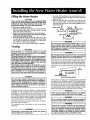
Filling the Water Heater
CAUTION
Never use this water heater unlessit is completely filled
with water. To prevent damage to the tank, the tank must
be filled with water. Water must flow from the hot water
faucet before turning "ON" gasto the water heater.
To fill the water heater with water:
1. Close the water heater drain valve by turning the handle to the right (clockwise). The drain valve is on the
lower front of the water heater.
2. Open the cold water supply valve to the water heater.
NOTE: The cold water supply valve must be left open
when the water heater is |rl use.
3. To insure complete fillin_ of the tank, allow air to exit
by opening the nearest hot water faucet. Allow water
to run unti/a constantflow is obtained. This will let air
out of the water heater and the piping.
4. Check all new water piping for leaks. Repairas needed.
Venting
WARNING
VENT DAMPERS- Any vent damper,whether it is operated
thermally or otherwisemust he removedif its useinhlbits
proper drafting of the water heater.
Thermally OperatedVent Dampers:Gas-firedwater heaters
having thermal efficiencyin excessof 80% may producea
relatively low flue gastemperature.SuchtemperaturesmaX
nut be high enoughto properly open thermally operated
v_nt dampers. Thlswould causespillageof flue gasesand
may causecarbon monoxidepoisoning.
Vent dampersmust bear evidenceof-certificati0n as complying with the latest edition of the American National
Standard ANSI Z21.68 (ANSI Z21.66 & 67, respectively,
cover electricallyand mechanically actuatedvent dampers).
Before installation of any vent damper, consult the local
SearsService Centeror gasutility for further information.
1. Place the draft hood legs in the receiving holes on the
top of the water heater. The legs will snap in the holes
to give a tight fit.
2. Place the vent pipe over the draft hood. With the vent
pipe in position, drill a small hole through both the
vent pipe and draft hood. Secure them together with a
sheet metal screw.
DRAFT HOOD
_r
VENE.w=,_
!
_rDRA
FT HOOD
!
HO.<"_
I
L_ VENT TO OUTDOORS
if-OR CHIMNEY
DRAFT _
WARNING
The water heaterwith draft hoodinstalledmustbe connected to a chimney which terminatesto the outdoors.Never
operatethe water heater unlessit is ventedto the outdoors
and hasadequateair supplyto avoidrisksof improperoperation, explosionor asphyxiation.
WARNING
diameterof thedrafthoodoutleton thewaterheater,andmust
I The vent pipefrom the water heatermustbe no lessthanthe
slopeupwardto the chimneyat least'/4inchperlinearfoot.
All vent gases must be completely vented to the outdoors
of the structure (dwelling). install only the draft hood provided with the new water heater and no other draft hood.
Vent pipes must be secured at each jointwith sheet metal
screws.
,,.,NC.
,sE
LINEAR FOOT
I
!
WARNING
VENT PIPEINSTALLATION
To insure proper ventingof this gas-firedwater heater,the
correctvent p}_oe
diametermustbe utilized.Any additionsor
deletionsof otEergasapplianceson a commonventwith this
waterheater may adverselyaffect the operationof the water
heater.Consultthe localSearsService(_enteror gasutility if
anysuch changesare planned.
There must be a minimum of 6 clearance betweensingle wa I
vent pipe and any combustible material. Fill and seal any clearance between single wall vent pipe and combustible material
with mortar mix, cement, or other noncombustible substance.
Forother than single wall, follow vent pipe manufacturer's
clearancespecifications.To insurea tight fit of the vent pipe in a brick
chimney,sealaround the vent pipe with mortar mix cement.
For proper venting in certain installations, a larger diameter
vent pipe may be necessary. Due to great variances in
installations, unforeseeable by the manufacturer of the
water heater, you must consult your gas company to aid
you in determining the proper venting for your water heater
from the vent tables in the latest edition of the National Fuel
Gas Code ANSI Z223.1, also referred to as NFPA 54.
Check the venting system for signs of obstruction or deterioration and replace if needed.
The combustion and ventilation air flow must not be
obstructed.
WARNING
/
Obstructed or deteriorated vent systems may present[
serious health risk or asphyxiation.
J 12
WARNING
and
combustiblematerial
will resultin afire hazard.
Failure
to have required clearancesbetween
vent piping
WARNING
I dangerous
Besurevent
flue
pipe
gases
isproperlyconnected
whichcould
causedeadlyasphyxiation.
to preventescapeof '1
WARNING
Chemicalvapor corrosionof the flue and vent systemmay
occurif air for combustioncontainscertainchemicalvapors.
Spraycan propellants,cleaning solvents,refrigeratorand air
conditionerrefrigerants,swimmingpool chen_icals,calcium
and sodiumchloride,waxes,bleachand processchemicals
are typicalcompoundswhichare potential|ycorrosive.
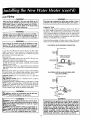
Gas Piping
WARNING
WARNING
Make sure the gassuppl!ed is the same type listed on the
model rating plate./ne Jme[ gas pressure must not exceed 14
inches water column [I/2 pound per square inch (3.5kPa)].
The minimum inlet gas pressure listed on the model rating
plate is for the purpose of input adjustment.
!
I resistant
se pipe to
joint
or teflon [Propane
tape marked
asgases.
being|
the compound
action of petroleum
(L.P.)]
SEDIMENT TRAP
A sediment trap shall be installed as close to the inlet of
the water heater as practical at the time of water heater
installation. The sediment trap shall be either a tee fitting
with a capped nipple in the bottom outlet or other device
recognized as an effective sediment trap. If a tee fitting is
used, it shall be installed in conformance with one of the
methods of installation shown below.
WARNING
If the gas control valve is subjected to pressuresexceeding '/2
i pound-per
square
inchin(3.5kPa),
damage
to the
gas con|rol valve could
result
a fire or the
explosion
from
leak|ng
gas.
Connecting the gas piping to the gas control valve of the water
heatercan be accomplishedby either of the two methodsshown.
WARNING
If the main gas line shutoff serving all gas appliances is used,
also turn "OFF" the gas at each appliance. Leave all gasappliancesshut oH until the water heater installation is complete.
L
GAS PIPING WITH
_[_GAS
A gas line of sufficient
size must be run to the water
heater. Consult the latest edition of National
Fuel Gas
Code ANSI Z223.1, also referred to as NFPA54 and the
gas company concerning pipe size.
There must be:
-A readily accessible manual shut off valve in the gas supply line serving the water heater, and
"A drip leg (sediment trap) ahead of the gas control valve
to help prevent dirt and foreign materials from entering
the gas control valve.
"A flexible gas connector or a ground joint union between
the shutoff val_,e and control valve to permit servicing of
the unit.
IlK
] I[_
VALVE
_J__
SUPPLY
PIPING
I
GROUND JOINT
UNION (Optional)
GAS
CONTROL
VALVE
T
6.
DRIP LEG
(Sediment
trap)
CAP
GAS PIPING WITH ALL BLACK IRON
TO GAS CONTROL
Standard Models are for installation
up to 3,300 feet
above sea level.
High Altitude Models are for installation from 3,300 to
5,500 feet above sea level.
Ifa standard model is installed above 3,300 feet or a high
altitude model is installed above 5,500 feet, the input rating must be reduced at the rate of 4 percent for each
1,000 feet above sea level. Contact
your local Sears
SeWice Center or gas ut I ty for further information.
PIPE
GAS SUPPLY PIPING
MANUAL]_-
I
SHUTOFF
ll_Ll
VALVE
_
"-_
GROUND
WARNING
6"
I
CONTROL
VALVE
GAS
_
I J DRIP LEG
H
WAR N IN G
BLACK PIPE
JOINT [t:::_
UNION.._
i,The appliance and its gas connection must be leak test- I
Led before placing the appliance in operation,
I
,
MANUAL
SHUTOFF
FLEXIBLE GAS CONNECTOR
LABELED
AS COMPLYING
WITH
ANSI STANDARDS
Be sureto check all the gas piping for leaks before lighting
the water heater. Use a soapy water solution, not a match
or open flame. Rinse off soapy solution and wipe dry.
.....
FLEXIBLE CONNECTOR
(Sediment trap)
CAP
WARNING
appliance and its individual shutoff valve must be discon|ned_ from the gas supply piping systemduring any pressure
llesting of that system at test pressures in excess of' I/2 pound
inch (3.5kPa).
_square
. .
ll_
appliance must be isolated from the gas supply piping sysJte_n_
by closing its individual manual shutoff valve during any
Ipressure testing of the gas supply piping system at test presqual to or lessthan 1/2pound per square inch (3.5kPa).
Contaminants in the gas lines may cause improper operation
of the gas control valve that may result in fire or explosion.
Before attaching the gas line be sure that all gas pipe is clean
on the inside. "to trap any dirt or foreign material in the gas
supplyline, a drip leg (sometimes caged a sediment trap)
mustbe incorporated-in the piping. The drip leg must De
readily accessible. Install in accordance with the "Gas
Piping_ section. Refer to the latest edition of the National
Fuel Gas Code, ANSI Z223.1, also referred to as NFPA 54.
13
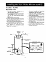
Installation
Checklist
BEFORELIGHTING THE PILOT:
6. Is there proper clearance between the water heater
and anything
that might catch fire? See the
"Locating the New water Heater" section.
7. Do you have adequate
ventilation
so that the
water
heater
will
operate
properly?
See
"Combustion
Air and Ventilation"
in the "Locating
the New Water Heater" section.
1. Check the gas lines for leaks.
a. Use a soapy water solution.
DO NOT test for gas
leaks using a match or open flame.
b. Brush the soapy water solution
on all gas pipes,
joints and fittings.
c. Check for bubbling soap, This means you have a
leak. Turn "OFF" gas and make the necessary
repairs.
d. Recheck for leaks.
e. Rinse off soapy solution and wipe dry.
2. Is the new temperature-pressure
relief valve properly
installed
and piped to an adequate
drain?
See
"Temperature-Pressure Relief Valve" section.
3. Are the cold and hot water lines connected
to the
water heater correctly? See "Water Piping" instructions
in the "Installing the New Water Heater" section.
4. Is the water heater completely
filled with water? See
"Filling" instructions
in the "Installing the New Water
Heater" section.
5. Will a water leak damage anything?
the New Water Heater" section,
8.
Is the draft hood vent piping properly secured? See
"Venting"
instructions
in the "Installing
the New
Water Heater" section.
9. Is there proper clearance
between the vent pipe
and anything
that might
catch on fire? See
"Venting"
instructions
in the "Installing
the New
Water Heater" section.
10. Is the vent pipe properly sloped and does the vent
terminate outdoors? See "Venting"
instructions in
the "Installing the New Water Heater" section.
11. Do you need to call your gas company to check
the gas pipe and its hookup?
See the "Locating
VENT PIPE TO
OUTDOORS
OR CHIMNEY
UNION
SHUTOFF
HOT
VALVE
COLD
DRAFT
HOOD
TEMPERATURE-PRESSURE
RELIEF VALVE
DISCHARGE PIPE
(Do not cap or plug)
GAS SUPPLY
SHUTOFF
VALVE
TEE
DRIP LEG
(Sediment trap)
PIPE CAP
6 INCH
DRAIN
VALVE
FLOOR
DRAIN
14
AIR GAP
WARNING
IEFORE LIGHTING [PROPANE (L.P.) GAS WATER
_EATERS]: Propane (L.P..) gas is heavier than air.
ihould,there be a leak in the system,the gas will settle
_ear the_rouna., uasements, crawl spaces, skirted
areas unaer mooue nomes (even when ventilated),
closets and areas below ground level will serve as
pockets for the accumuFation of this gas. Before
attempting to light or reli_ht the water heater's pilot or
turning on a nearby electr,cal light switch, be absolutely sure there is no accumulated gas in the area. Search
for odor of gas by sniffing at ground level in the vicinity of the appliance. If odor is detected, follow the steps
indicated at "For Your Safety" on the cover page of
this manual, then leave the premises.
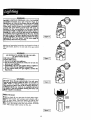
Figure 6 [
Lightingand operating instructions are located on front of
the water heater, above or to one side of the gas control
valve.
WARNING
• AN ODORANT
IS ADDED TO THE GAS USED
BY THIS WATER HEATER.
FOR YOUR SAFETY
IF YOU SMELL GAS:
I Figure 7 [
1. Do not try to light any appliance.
2. Do not touch any. electrical switch; do not use any
phone in your building.
3. Immediately call your gas supplier from a neighbor's
, p.hone. Follow the gas s-upplie"r"s instructions.
4. It you cannot reach your gas supplier, call the fire
department.
WARNING
[ Figure 8 ]
i DO NOT force the gas control
knob. Use only your
I ,lland to push it down to light the pilot, or to turn it to
I _ON", _OFF" or "PILOT".
Never use a tool such as a
I lever, wrench or pliers. Do not hit or damage the knob.
I A da_n-aged knol} may result in an explosion aid serii .ousinju_-y_lf you have problem turning the knob, call
th_thegas s_plsupplier
immediately
_! HECK FOR LEAKS
INNER
DOOR
_Be_re to check all your gas pipes for leaks before lighti!ng your water heater. Use a soapy water solution, not a
!thatch or open flame Check the factory gas fittings after
Pilot is lit and gas con'trol knob is still in "PILOT" position.
iT,h_en, check the fittings when the main burner is turned
ON".
Use a soapy water solution for this, too.
OUTER
DOOR
Figure 9 ]
15
FOR YOUR
SAFETY
READ
BEFORE
LIGHTING
If you do not follow these instructions exactly, a fire or explosion
I may result causing propertyWARNING
damage, personal injury or loss of life. I
This appliancehas a pilot whichmust be lightedby
hand.Whenlightingthepilot,followtheseinstructions
exactly.
BEFORELIGHTINGsmellall aroundtheappliancearea
for gas. Be sure to smell next to the floor because
somegasis heavierthanair and willsettleon thefloor.
WHATTODOIF YOUSMELLGAS
A,
B.
C.
• If you cannotreach your gas supplier,cell the fire
department,
r
Useonlyyourhandto pushin or turnthe gascontrol
knob.Never use tools,ff the knobwill not pushin or
turn byhand,don'ttry to repair it, cell a qualifiedservice technician.Forceor attemptedrepair mayresult
In a fire or explosion,
Do not usethis applianceff any part has beenunder
water.Immediatelycell a qualifiedservicetechnician
to inspectthe applianceand to replaceanypart of the
controlsystemand any gas controlwhichhasbeen
underwater.
D,
Do not touch any electric switch;do not use any
i phonein
o nottryto
lightanyappliance,
yourbuilding.
Immediatelycallyourgassupplierfrom a neighbor's
phone.Followthegassuppliers instructions.
LIGHTING
INSTRUCTIONS
9. Push in control knob all the way and hold down.
Immediatelylightthe pilot with a match.Continueto
hold control knob in for aboutone (1) minuteafter
the pilot is lit. Releaseknoband it will pop backup.
Pilot shouldremainlit. If it goes out, repeatsteps3
through8.
• If knobdoes not pop up whenreleased,stop andl
immediatelycall your service technicianor gasl
supplier.
• If the pilot will not stay lit after several tries,
1. STOP!Readthesafetyinformation
aboveon this label.
2. Removeouterdoor.
3. Set the thermostatto lowest setting by turning the
watertemperaturedialclockwise,(( _,) to itslowest
temperaturesetting (witharrowon dial)as shown.DO
NOT FORCE.
4. Turngascontrolknobclockw-ise _, _ to ",OFF"position. Knobcannotbe turned from 'PILOT to "OFF"
unlessknob is depressedslightly.DO NOT FORCE.
(Figure6,page15)
5. Waitfive (5) minutesto clear out any gas. If you then
smellgas, STOP!Follow B in the safety information
aboveon this label.If you don'tsmell gas, go to the
nextstep.
6. Remove(or open)inner door locatedbelowthe gas
controlunit.(Figure9, page15)
7. Findpilot-followmetaltube fromgas control.The pilot
islocatedontherighthandsideof theburner.
PILOT BURNER
depress_
_ and turn,the gascontrolknobclockwise
V
to' OFF andcell yourservicetechnician
or gassupplier.(Figure6, page15)
10. Replace(or close) inner door.Replaceouterdoor if
door does not cover gas controlon/offknobor temperatureadjustmentknob.(Figure9, page15)
11. At armslengthaway,turngascontrolknobcounterclockwise _
to the full "ON" position.
WARNING Do not use gas control knob to reg.
ulate gas flow, (Figure8, page15)
12. At arms length away,set the thermostatto desired
setting.The mark( • ) HOTindicativeof approximate
120°F is preferredstarting point. Some local laws
may requirea lowerstartingpoint.If hotterwateris
desired,seeinstructionmanualand"warning" below.
13.Replacetheouterdoorif notreplacedin step10.
_THERMOCOUPLE
8. If youdon'tsmellgas,turnknobon gascontrolcounter
clockwise_
_(_ to"PILOT"position.(Figure7, page15)
l Hotterwaterincreasesthe risk of scald injury.Beforechangingtemperaturesettingsee
WARNING
instructionmanual. j
TO TURN
OFF GAS TO APPLIANCE
2,Turngascontrolknobclockwise_')
to "OFF"position, Knobcannotbe turnedfrom "PILOT"to "OFF"
unlessknobis depressedslightly.DO NOT FORCE.
(Figure6, page15)
3. Replaceouterdoor(if removed),
1. Set the thermostatto lowestsetting by turningthe
watertemperaturedial clockwise(F_)
to its lowest
temperaturesetting(witharrowon dial) as shown.DO
NOT FORCE,
16
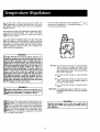
Turnthewatertemperature
dial clockwise(/"-_) to
decrease
thetemperature,
or counterclockwise
(_",_)
to increase
thetemperature.
Dueto the natureof the typicalgaswaterheater,the
watertemperature
in certainsituationsmayvaryup to
30°Fhigheror loweratthepointofusesuchas,bathtubs,
showers,
sink,etc.
Thismeans
thatwhenthetemperature
adjustment
dial is
setatthe markapproximating
120° F,theactualwater
temperature
at anyhot watertap could beas highas
150°For aslowas90°F.
Anywaterheater's
intended
purpose
isto heatwater.Hot
wateris neededfor cleaning(bodies,dishes,clothing).
Hotwaterwill present
a scaldhazard.Depending
onthe
timeelement,andthe peopleinvolved(normaladults,
Children,
toddlers,elderly,infirm,etc.)scaldingmay
occuratdifferenttemperatures.
WARNING
HOTTER WATER CAN SCALD: Water heaters are
ntended to produce hot water. Water heated to a temperature which will satisfy clothes washing, dish washng_ and other sanitizing needs can scald-and permalently injure you upon contact. Some people are more
ikely to be permanently injured by hot water than oth._rs.These include the elderly, children, the infirm, or
physically/mentally handicapped. If anyone using hot
water in your home fits into one of these groups or if
there is a local code or state law requiring a certain
temperature water at the hot water tap, then you must
take special precautions. In addition to using the lowest possibletemperature setting that satisfies your hot
Water needs, some type of tempering device, such as a
mixing valve, should be used atthe hot water taps used
by thesepeople or at the water heater.
Y HOT-Is a thermostat setting of approximately
120°F, which will supply hot water at the
most economical temperatures. The temperature adjustment knob can be turned lower
than "HOT" if desired.
A-Is a thermostat
130°F.
setting of approximately
B-Is a thermostat setting of approximately
140°E This is the lowest setting for supply of
hot water to dishwashers.
C-Is a thermostat
150°F.
WA R N ING
,
_e_er allow small children to usea hot water tap, or to
d_w their own bath water. Never leave a child or handin a bathtub or shower.
|_p ed ers0n unattended
setting of approximately
VERY HOT-Is a thermostat setting of 160°F. It is recommended that the dial be set lower whenever
possible.
p
of this water heater has been factory set at
position, to reduce the risk of scald injury. It is
and must be reset to the desired temperature
The mark (V) HOT indicative of approximately
the preferred starting point. Some states have a
for a lower setting. If you need hotter water,
_'directions for temperature adjustment, but beware
nings in this section.
WARNING
Should overheating occur or the gas supply fail to
shut off, turn "OFF" the manual gas control valve to
the appliance.
17
Start Up Conditions
CONDENSATION
Whenever the water heater is filled with cold water, a certain amount of condensation will form while the burner is
on. A water heater may appear to be leaking when in fact
the water is condensation. This usually happens when:
a. When a new water heater is filled with cold water
for the first time.
b. When gas burns and water vapor is produced in
water heaters, particularly high efficiency models
where flue temperatures are lower.
c. When you use large amounts of hot water in a short
time and the refill water is very cold.
sure relief valve is reached, the valve will relieve the
excess pressure. The temperature-pressure relief valve is
not intended for the constant relief of thermal expansion. This is an unacceptable condition and must be corrected.
It is recommended that any devices installed which could
create a closed system have a by-pass and/or the system
have an expansion tank to relieve the pressure built by
thermal expansion in the water system. Expansion tanks
are available for ordering through the Sears Service
Center. Contact the local plumbing inspector, water supplier, and/or the SearsService Center for assistance in controlling these situations.
Moisture from the products of combustion condense on
the cooler tank surfaces and form drops of water which
may fall onto the burner or other hot surfaces to produce
a "sizzling" or "frying" noise.
STRANGE
SOUNDS
Excessive condensation can cause pilot outage due to
water running down the flue tube onto the main burner
and putting out the pilot.
Possible noises due to expansion and contraction of some
metal parts during periods of heat-up and cool-down do
not represent harmful or dangerous conditions.
Because of the suddenness and amount of water, condensation water may be diagnosed as a "tank leak". After the
water in the tank warms up (about 1-2 hours), the condition should disappear.
Condensation causes sizzling and popping with the burner area during heating and cooling periods and should be
considered normal. See "Condensation" section.
Do not assume the water heater is leaking until there has
been enough time for the water in the tank to warm up.
Operational
An undersized water heater will cause more condensation. The water heater must be sized properly to meet the
family's demands for hot water including dishwashers,
washing machines and shower heads.
SMELLY WATER
In each water heater there is installed at least on anode
rod (see parts section) for corrosion protection of the tank.
Certain water conditions will cause a reaction between
this rod and the water. The most common complaint associated with the anode rod is one of a "rotten egg smell".
This odor is derived from hydrogen sulfide gas dissolved
in the water. The smell is the result of four factors which
must all be present for the odor to develop:
a. a concentration of sulfate in the supply water.
b. little or no dissolved oxygen in the water.
c. a sulfate redurLing bacteria within the water heater.
(This harmless bacteria is non-toxic to humans.)
d. an excess of active hydrogen in the tank. This is
caused by the corrosion protective action of the
anode.
Excessive condensation may be noticed during the winter
and early spring months when incoming water temperatures are at their lowest.
Good venting is essential for a gas fired water heater to
operate properly as well as to carry away products of
combustion and water vapor.
SMOKE/ODOR
It is not uncommon to experience a small amount of
smoke and odor during the initial start-up. This is due to
burning off of oil from metal parts, and will disappear in a
short while.
THERMAL
Conditions
Smelly water may be eliminated or reduced in some
water heater models by replacing the anode(s) with one
of less active material, and then chlorinating the water
heater tank and all hot water lines. Contact the local
water heater supplier for further information concerning
an Anode Replacement
Kit #9001453
and this
Chlorination Treatment.
EXPANSION
Water supply systems may, because of high line pressure,
frequent cut-offs, the effects of water hammer and others,
have installed devices such as pressure reducing valves,
check valves, back flow preventers, etc...to control these
types of problems. When these devices are not equipped
with an internal by-pass, and no other measures are taken,
the devices cause the water system to be closed. As water
is heated, it expands (thermal expansion) and closed systems do not allow for the expansion of heated water.
If the smelly water persists after the anode replacemer
and chlorination treatment, we can only suggest that con
tinuous chlorination and filtering conditioning equipmer
be considered to eliminate the water problem.
Do not remove the anode leaving the tank unprotecte(
By doing so, all warranty on the water heater tank
voided.
The water within the water heater tank expands as it is
heated and increases the pressure of the water system. If
the relieving point of the water heater's temperature-pres18
"AIR" IN HOT
WATER
NOT ENOUGH
FAUCETS
1. Check the manual gas shut off valve to be sure it is open.
2. Check the pilot flame. It may have gone out. All models
have an opening behind the outer door for viewing the
pilot.
3. If the pilot is not lit, follow the "Lighting" instructions in
this manual or located above the gas control valve on the
water heater to relight the pilot. If the water was extremely hot and is now cold, the high limit safety temperature
shut off may have put out the burner and pilot. If the high
temperature shut off activates, the gas control valve must
be replaced. Contact the Sears Service Center.
4. The gas control knob must be turned to the "ON" position.
5. The temperature adjustment dial may be set too low. See
the "Temperature Regulation" section.
6. The gas company can check the gas input to see if it is
correct. An underfired water heater will not heat water as
quickly.
7. Look for leaking or open hot water faucets. Make sure all
are closed.
8. The cold water inlet temperature may be colder during
the winter months. It will take longer to heat the water
and seem like less hot water.
9. If you cannot find what is wrong, call the 5ears Service
Center.
WARNING
HYDROGEN GAS. Hydrogen gas can be produced in a
hot water system that has not been used for a long period of time (generally two weeks or more). Hydrogen _as
is extremely flammable and explosive• To prevent the
_ibility
of injury under these conditions, we recomrnend the hot water faucet be opened for several minutes at the kitchen sink before any electrical appliances
which are connected to the hot water system are used
(such as a dishwasher or washing machine). If hydrogen
,as is present, there will probab|y be an unusual sound
imdar to air escaping through the pipe as the hot water
aucet is opened. There must be no smoking or open
lame near the faucet at the time it is open.
HIGH TEMPERATURE
SHUT
OFF SYSTEM
This water heater is equipped with an automatic gas shut
6if system. The high temperature shut off is built into the
g_s control valve. This system shuts off the gas supply to
the water heater burners when high water temperatures
_e present. It is non-resettable.
If the high temperature
shut off activates, the gas control valve must be replaced.
if this were to occur, turn "OFF" the entire gas supply to
[_e water heater. Contact the Sears Service Center.
[ihould
overheating
WATER IS TOO
HOT
1. The temperature adjustment dial may be set too high. See
the "Temperature Adjustment" section.
NOTE: A period of time is necessary after an adjustment
has been made for the water temperature to reach the
new temperature setting.
WARNING
occur or the gas supply fail to
Iishut off, turn "OFF -_' the manual gas control valve to
ibe appliance
lting
OR NO HOT WATER
2. If lower temperature settings will not lower the water
temperature, call the Sears Service Center.
System Inspection
Obstructions
and deteriorated
vent systems may pre-
. sent serious health riskWARNING
or asphyxiation.
i_tonce a year a visual inspection should be made of
!nting system. You should look for:
_structions which cou d cause improper venting. The
mbustion and ventilation
air flow must not be
gtructed.
:mage or deterioration which could cause improper
iting or leakage of combustion products.
_tedflakes around top of water heater.
WARNING
Be sure the ventpiping
is properly connected to prevent escape of dangerous flue gasses which could
cause deadly asphyxiation.
WARNING
__!!m[Calvapor corrosion of the flue and vent system may
_ur if air for combustion contains certain chemical vapors.
WARNING
If after inspection of the vent system you found sooting or
deterioration, something is wrong. Call the local gas utility
to correct the problem and clean or replace the flue and
venting before resuming operation of the water heater.
19
L.P. Gas Control Valve & Burner
AssemblyReplacementInformation
Burner Inspection
WARNING
Do not usethis applianceif any part of it has been under
water. Immediately call a Sears Service Technician to
inspectthe applianceand to replace the gascontrol or any
part of the burnersystemwhichhas been underwater.
WARNING
PROPANE (L.P.) GAS CONTROL VALVE AND BURNER
ASSEMBLY REPLACEMENT INFORMATION.
For Propane (L.P.) Gas Models Only:
At least once a year a visual inspection should be made
of the main burner and pilot burner. The drawing is for
your reference.
Your water heater is equipped with a Propane (L.P.)
gas control valve and a maln burner assembly with left
hand threads for the following fittings and their connections.
You should check for sooting which is not normal and
will impair proper combustion.
(1) The connection between the manifold and the gas
control valve (A to B) are left hand threads.
(2)
The connection between the main burner orifice
and the manifold (C to D) are left hand threads.
For ordering these replacement parts, please refer the
the II Repair Parts" sechon of this manual.
WARNING
Soot build-up indicates a problem that requires correction before further use. Turn "OFF" gas to water heater
and leave "OFF" until repairs are made, because failure to correct the cause of the sooting can result in a
fire causing DEATH, SERIOUS BODILY INJURY, OR
PROPERTY DAMAGE.
Burner Cleaning
In the event your burner needs cleaning, use the following
instructions:
if inspection of the burner shows that cleaning is required,_
turn the gas control knob clockwise (/,"_)
to the "OFF
position, depressing slightly.
Housekeeping
NOTE: The knob cannot be turned from "PILOT"
to
"OFF" unless knob is depressed slightly. DO NOT FORCE.
Vacuum around base of water
lint on a regular basis.
Loose deposits on or around the burner can be removed
by carefully using the hose of a vacuum cleaner inserted
through the access door of the water heater. If the burner
needs to be removed for additional cleaning, call the Sears
Service Center to remove and clean the burner and correct
the problem that required the burner to be cleaned.
heater for dust, dirt, and
WARNING
INSTALLED IN SUITABLE AREA: To insure sufficient ventilation and combustion air supply, proper clearances from
the water heater must be maintained. See "Locating the
New Water Heater" section. Combustible materials such as
clothing, cleaning materials, or flammable liquids, etc.
must not be placed against or adjacent to the water heater
which can cause a fire.
2O
mperature-Pressure
Refief
Draining
lye Operation
temperature-pressure
relief valve
ated at least once a year.
DISCHARGE
The water heater should be drained if being shut down
during freezing temperatures. Also periodic draining and
cleaning of sediment from the tank may be necessary.
1. Turn the gas control knob to the "OFF" position.
2. CLOSE the cold water inlet valve to the water heater.
3. OPEN a nearby hot water faucet and leave open to
allow for draining.
4. Connect a hose to the drain valve and terminate to an
adequate drain.
5. OPEN the water heater drain valve to allow for tank
draining.
NOTE: If the water heater is going to be shut down
and drained for an extended period, the drain valve
should be left open with hose connected allowing
water to terminate to an adequate drain.
6. Close the drain valve.
7. Follow instructions in the "Filling The Water Heater"
section.
8. Follow the lighting instructions in the "Lighting" section
to restart the water heater.
must be manually
PIPE
WARNING
_n checking the temperature-pressure relief valve
ration, make sure that (1) no one is in front of or
Jnd the outlet of the temperature-pressure relief
e dischargeline, and (2) that the water manually dis_gedwill not causeany property damagebecause the
er may be extremely hot.
fter manually operating the valve, it fails to completeeset and continues to release water, immed|ately
;e the cold water inlet to the water heater, follow the
ning instructions,and replace the temperature-prep
._relief valve with a new one.
Drain Valve Washer
Replacement
NOTE: For replacement, usea '%5"x "/," x %" thick washer
available at your nearest hardware store. For ordering
replacement washers,refer to the "Repair Parts" section.
1. Turn "OFF" gas supply to water heater.
2. Follow "Draining" instructions.
3. Turning counter clockwise, remove the hex cap below
the screw handle.
4. Remove the washer and put the new one in place.
5. Screw the handle and cap assembly back into the drain
valve and retighten using a wrench. DO NOT OVER
TIGHTEN.
6. Follow instructions in the "Filling The Water Heater"
section.
7. Check for leaks.
8. Follow the lighting instructions in the "Lighting " section to restart the water heater.
're to install and maintain a new properly listed tem:ure-pressure relief valve will release the manufactur_m any claim which might result from excessive temture or pressure.
WARNING
._temperature-pressurerelief valve on the appliance
}s or discharges periodically, this may be'due to
hal expansion. Your water heater may have _ check
._installed in the water line or a water meter with a
ck valve. Consult the SearsService Center for further
)rmation. Do not plug the temperature-pressure
_fvalve.
__HANDLE
AND
nk (Sediment) Cleaning
ment build-up on the tank bottom may create varying
rots of noise, and if left in the tank will cause prematank failure. In some water areas, you may not be
to drain all sediment deposits by simply draining the
. In these cases Mag Erad(part no. 3515) can be used
elp remove the sediment deposits. This may be
red from the Sears Service Center. For ordering, refer
e "Repair Parts" section.
Service
If a condition persists or you are uncertain about the
operation of the water heater, let a qualified person check
it out. Call the Sears Service Center.
21
Usethisguideto checka "Leaking"waterheater.Many
suspected"Leakers"arenot leakingtanks•Oftenthe
sourceofthewatercanbefoundandcorrected•
CAUTION
Read this manual first. Then before checking the water
heater make sure the gas supply has been turned _IOFF",
and never turn the gas "ON" before the tank is completely full of water.
If you arenot thoroughlyfamiliarwith
gascodesyour
•
,I
water heater, and safety practices, contact the Sears
Service Center to check the water heater.
CAUTION
Never use this water heater unless it
with water. To prevent damage to the
be filled with water. Water must flow
faucet before turning "ON" gas to the
O
is completely filled
tank, the tank must
from the hot water
water heater.
Water at the draft hood is water vapor which has
condensed out of the combustion products. This is
caused by a problem in the vent. Contact the Sears
Service Center•
O
Condensation may be seen on pipes in humid
weather or pipe connections may be leaking.
O
*The primary anode rod fitting may be leaking•
Q
Small amounts of water from temperature-pressure
relief valve may. be due to thermal expansion or high
water pressure in your area.
* The temperature-pressure
ing at the tank fitting.
Water from a drain
opened slightly.
O
relief valve may be leak-
valve may be due to the valve
*The drain valve may be leaking at the tank fitting.
Combustion productS contain water vapor which can
condense on the cooler surfaces of the tank. Droplets
form and drip into the fire or run on the floor. This is
common at the time of startup after installation and
when incoming water is cold.
O
®
Water in the water heater bottom or on the floor may
be from condensation, loose connections, or the
relief valve. DO NOT replace the water heater until
a full inspection of all possible water sources is made
and necessary corrective steps taken.
Leakage from other appliances, water lines, or
groundseepage should also be checked.
* To checl_ where threaded portion enters tank, insert Q-Tip between jacket opening and fitting. If cotton is wet, follow
"Draining" instructions in the "Periodic Maintenance" section and then remove fitting. Put pipe dope or teflon tape on the
threads and replace. Then follow "Filling the Water Heater" instructions in the "Installing the New Water Heater" section.
22
23
POWER MISER _ 8 GAS WATER HEATERS
MODEL
NUMBERS:
153.335200
153.335250
153.335251
153.335302
153.335350
153.335351
40
40
40
30
30
30
Gal. High Altitude
Gal.
Gal.
Gal. High Altitude
Gal.
Gal.
18
16
19
0
1
17
\
2
4
14
11
2O
6
24
dER MISER_
8 GAS WATER HEATERS
)EL NUMBERS:
40
40
40
30
30
30
Gal. High Altitude
Gal.
Gal.
Gal. High Altitude
Gal.
Gal.
MODEL
153.335200
153.335250
153.335251
PART DESCRIPTION
Temperature-Pressure
153.335350
Relief Valve
9000071L.9000071,/
9000071,t9000071_/
_'" 9000734 ,., / 9000734
9001829 _./'9001829
_'" 0270118 li /_270118L.0270118
t. /0270118
- " 9000058
19000058
_- t9000058-_
_9000058
9000071_/
90001829 v
Model Rating Plate 4Drain Valve
270118
9000058
Drain Valve Washer
('¥35"x '3/64"x l/a"thick)**
9001584
F145-0085./
Clip
Pilot Tubing w/Fittings
Burner Orifice
Manifold
Burner w/Pilot
Burner
Manifold Cover
Inner Door
Gas Control Valve
Temperature Adjustment Knob
Dip Tube Spacer/Washer
Dip Tube
Flue Baffle
Draft Hood
Restrictor Ring
Pilot
Pilot'Clip
Pilot Orifice
Manual
153.335302
153.335351
PART NUMBERS
Primary Anode Rod
Thermocouple
Thermocouple*
NUMBERS
t
/ 9001584
9001584 _ "9001584v
i
F145-0085
_ iF145-0085
F145-0085 v
42-9231 v
42-9231 _. /42-9231v
_ 42_231 _
9000278
9000278 _
9000278 _ t'K)00278_-- 0230141
/"0230141
0230130!
o23o182/
#40 .V
#37 1,,'
#37
V'
#37 V /
9001626 v / 9001665
/ 9001665J
9000739
F145-0096
' F145-0096
9000358
19000338_
9000281 _ "'9000281
F145-0842
IF145-0842l
F145-0697_
0530087
V
9001981
F145-0697_
0530087
0530087
0530087
i
F145-0089 _ /F145-0089
F145-0099 - /F145-0099_
_-45-0609:,
,F145-0089 " F145-0089ia
m45-0099145:0y9
0291319
3515
ese parts are also available at most Sears retail stores.
Iso available at most hardware stores.
Jaced only on return of damaged plate.
_t lllustrated
i'
i
,--9000058.
I
9000278
., 23o 2o
--
#33
9000739
9000358_
/9000281
_F145-0697_
IF145-0697
_.+
1
i
-_
I
_9001193
9000273
/9000275
F145-0609
l
%
.-F145-0089_
"F145-0099_
_"
WHEN ORDERING
REPAIR PARTS, ALWAYS GIVE THE
FOLLOWING
INFORMATION:
MODEL NUMBER
NAME OF ITEM
PART NUMBER
PART DESCRIPTION
THIS IS A REPAIR PARTS LIST, NOT A PACKING
25
/-
0530087
9001698_
The model number of your Gas Water Heater will be
found on the model rating plate located above the gas
control valve.
parts listed may be ordered from any Sears Service
ter and most Searsstores.
i j
9000703
_F145-0842_
/F145-0089_
/_145-0099_.
i
i
."1=145-0842
0530087
9001698
"
If the parts you need are not stocked locally, your order
will be electronically
transmitted to a Sears Repair Parts
Distribution
Center for handling.
v that you have purchased your Gas Water Heater,
_ld a need ever exist for repair parts or service, simply
act any SearsService Center. Be sure to provide all per_tfacts when you call or visit.
_
l"
"i9001584_
" 9000739
9001981
_
9001698_._
9001193
_
9000300_,,
1 9001193 "j
_ t9000273
u /,9000273
_ " 9000273
d/9000275
_ / 9000275
_ ! 9000275
9000300"11
9000273
/ 9000273
9000275
, 9000275
Mag-Erad
_9_0278.../0230120
'#33.
f145-0096 - "F145-0096_.
#
9000703 _
9000358 _ 19000358
9000358--19000281 _ _9000281
/ 9000281
,_F145-0842_145-0842
9000734
/_0270118
-'1_145-0085_. _.-145-0085_
42-9231_/
42-9231
/
F145-0697_ _F145-0697c
9oo1981f
9000300
19001584f
9000071_
"I
335200
335250
335251
335302
335350
335351
LIST.
i
POWER MISER_ 8 GAS WATERHEATERS
MODEL NUMBERS:
153.335400
153.335450
153.335451
153.335502
153.335550
153.335551
40 Gal. High Altitude
40 Gal.
40 Gal.
50 Gal. High Altitude
S0 Gal.
S0 Gal.
18
\
2
11
2O
.26
OWER MISER_
8 GAS WATER HEATERS
IODEL NUMBERS:
53.335400
53.335450
53.335451
53.335502
53.335550
53.335551
40
40
40
50
50
50
Gal. High Altitude
Gal.
Gal.
Gal. High Altitude
Gal.
Gal.
MODEL
KEY
NO.
1
2
153.335450
153.335400
PARTDESCRIPTION
Temperature-Pressure Relief Valve
Primary Anode Rod
3
Model Rating Plate i-
4
5
Drain Valve
Drain Valve Washer
thick)**
(17//32
I1 X
13/64
I'
X
VB 'l
6
7
8
9
Thermocouple Clip
Thermocouple*
Pilot Tubin B w/FittinBs
Burner Orifice
10
11
11
Manifold
Burner w/Pilot
Burner
12
13
14
Manifold Cover
Inner Door
Gas Control Valve
15
16
16
1:_
17
Temperature Adjustment Knob
Dip Tube Spacer/Washer
Dip Tube
Flue Baffle
!.18
.19
20
Draft Hood
Restrictor RinB
Pilot
Z#
#
_#
#
Pilot Clip
Pilot Orifice
Manual
Mag-Erad
153.335451
NUMBERS
153.335502
PART NUM[[_ERS
153.335550
/
/
153.335551
4;
,
_000071
9000071 _
00071V
9000071 I_' • 9000071 u /9000071
9000734_/4 9000734_ /9000734
,,"9000734
c_ 1
_/9000734
L _9000734
U
0270118
O27O118
0270118
0270118
0270118
0270118
9000058 \ /9000058
9000058
9000058 u 19000058 _-"
9000058l/
9001584 tj /_F_01584 L '/9001584
/9@1584 "_9001584 G /9001584 i_,145-0085
45-oo85
t
"_45-0085_ "_-_45-0085c -- 45-oo85cF145-0085_
/ 42-9231v
42-9231_.I
42-9231
_2-9231L., /42-9231t,,,
42-9231_"
,/9000278_
/9000278
/9000278 _
9000278 _. /9000278 L /9000278
0230141
0230120
0230120 _99_0!0141
0230120
0230120
#33
.
#33 _--_
#37 C/ _: #33
37 k...--90016261/
9_01626_ /9001626
1665.,v _9001665L., / 9001665_.,,, /
_.-F145-OO9&"
F145-0096 _, "1ff145-0096_ /
-_],45-0096£
9000703 /"
9000703t.,
--y
.-9000358-- ----9000358_- 9000358o, /_000358_
/9000358
L /9000358
9000281 It /9000281 • _000281
.9000281 _
/9000281i. ,, /9000281,/
F145-0842b /F145-0842_ "_4'5-0842_
"F145-O842L,-_1_45-084g_. /:145-0842_-_
_145-0697
/F.1,45-0697_ / F/I"i15-0697_"
F145-0697_.,JF]45-0697_ /F1_5-0697_
/'6530087
--_30087g,." _0530087_ / 0530087
0530087_ /0530087_
900169g_ "
9001698_
9001698j
9001698_
9001698tj
9O01698
9000516_" ' 9O00516 /9000516_-9000298
9000298 >
9000298 ,/
9000273
/9000273_
9000273 _.,/
9000273 lJ
-'900027 .., 00273
,.'9"000275_ _000275
9000275 _s'
_., /
9000275 _/9000275
/9000275_
....
F145'0609_1
.F145:0609
_ "1_45-0089x .,.I_1__0089 _._
F145-0089_ "_I'45-0089_ _i45-0089_'1_45-0089
F145-0099/'
_45-0099_
i Tt_eseparts are also available at most Searsretail stores.
)* Also available at most hardware stores.
..g_45-OO99t_-O099_
0291319 -3515
F145-009_
If the parts you need are not stocked locally, your order
will be electronically transmitted to a Sears Repair Parts
Distribution Center for handling.
Replaced
only on return of damaged plate,
Not Illustrated
The model number of your Gas Water Pleater will be
found on the model rating plate located above the gas
control valve.
_ow that you have purchased your Gas Water Heater,
ihould a need ever exist for repair parts or service, simply
10ntactany SearsService Center. Be sure to provide all per-
WHEN ORDERING
REPAIR PARTS, ALWAYS GIVE THE
FOLLOWING
INFORMATION:
MODEL NUMBER
NAME OF ITEM
PART NUMBER
PART DESCRIPTION
iJhentfacts when you call or vis t
_11parts listed may be ordered from any Sears Service
_ienterand most Searsstores.
THIS IS A REPAIR PARTS LIST, NOT A PACKING
27
LIST.
_ _
•
•
i
POWER MISER_
MODEL
¸•
8 GAS WATER HEATERS
NUMBERS:
153.335600
153.335650
153.335651
153.335750
153.335751
65
65
65
50
50
Gal. High Altitude
Gal.
Gal.
Gal.
Gal.
18
16
19
17
2
14
11
2O
28
WER MISER_
8 GAS WATER HEATERS
)DEL NUMBERS:
5.335600
3.335650
L335651
3.335750
3.335751
65
65
65
50
50
Gal. High Altitude
Gal.
Gal.
Gal.
Gal.
MODEL
KEY
NO.
1
Primary Anode Rod
Model Rating Plate ±
Drain Valve
5
Drain Valve Washer
(1%2"x 13/_,,x Vs"thick)**
Thermocouple
Clip
7
Thermocouple*
8
9
Pilot Tubing w/Fittings
Burner Orifice
10
11
Manifold
12
13
14
9000071
9000734
0270118
9000071
9000734
0270118
9000058
/ 9000058_
153.335651
Burner w/Pilot
Burner
Manifold Cover
Inner Door
9001584
9001584 i
F145-0085_
153.335751
153.335750
PA_T NUMBERs
Relief Valve
3
4
11
153.335650
PART DESCRIPTION
Temperature-Pressure
2
6
153.335600
NUMBERS
_9000071/
_" 9000734
0270118
_
/ 9000058
9000071
9000734
0270118
/9000071_
,_
/ 900073.,'4
0270118
v/9001584
F145-0085_/F145-0085_/F145-0085u_F145-0085_
42-9231V
,42-9231i,.'/
42-9231 _
_2-9231V/!
:_2-9231W
9000278_/9000278
_/9000278_
9000278 V /9000278_
0230120
0230120
0230124
0230124
0230130
#37
#33
#33
_ #30
/
#30
9001626L_
_/9001665_'_[301665_
F145-0096_ /9001711
/F145-0096 _9001711
_
F145-0096 g
.,
90003581,/
-
9000703v
-
9000281V
FI'45-0089_/F145-0089 _414_-0089 _ _PI S"OO81_
#
Pilot Clip
Pilot Orifice
Manual
#
Mag-Erad
2O
#
#
0530087
0530087
0530087
o >oo0
os oo 7, oo
/_,01982_'_ _ _001982 v
J
9000273
9000419_/9000419
i,,' / 9000273 _'/9000273
9000275
V
9000275
-
_ ,,,9000371
_
_000274
/9000275
_z_000297
/
F145-0609v
4
18
19
/
9000703._
F145-0697 L tF145-0697,/F145-0697_145-0697_--F145-0697,
9001982
9000516
/
9000358_
9000358 _/9'000358
_" 9000358
/ 9000281 _9000281
_-"9000281_9000281
/F145-0842_ -4_45-0842L_145-0842_-'F145-0842
Temperature Adjustment Knob
Dip Tube Spacer/Washer
Dip Tube
Flue Baffle
Draft Hood
Restrictor Ring
Pilot
17
i
e
F145-0842
16
16
_'_
1 _9001584V"
Gas Control Vaive
15
_/
9000058
_/9000058_
_"/9001584
/
_F145-0099---
/F 1145-0099_ ,,F_r_5-0099 _/_145-0099_
/
/
_" _0 0
_/9000274
_
_000297
_
F145-0609
/
__
F145-008_
_145-0099_
z
0291319
3515
If.the parts you need are not stocked locally, your order
will be electronically transmitted to a Sears Repair Parts
Distribution Center for handling.
These parts are also available at most Sears retailstores.
available at most hardware stores.
)laced only on return of damaged plate.
illustrated
The model number of your Gas Water Heater will be
found on the model rating plate located above the gas
control valve.
that you have purchased your Gas Water Heater,
a need ever exist for repair parts, or service, simply
any Sears Service Center. Be sure to provide all perfacts when you call or visit.
WHEN ORDERING
REPAIR PARTS, ALWAYS GIVE THE
FOLLOWING
INFORMATION:
MODEL NUMBER
NAME OF ITEM
PART NUMBER
PART DESCRIPTION
)arts listed may be ordered from any Sears Service
and most Searsstores.
THIS IS A REPAIR PARTS LIST, NOT A PACKING
29
LIST.
POWER MISER '-M8 GAS WATER HEATERS
MODEl.
NUMBERS:
153.335850
153.335851
153.335951
65 Gal.
65 Gal.
40 Gal. L.P.
18
16
19
l,
O
17
2
11
20
6
3O
NER MISER _8
GAS WATER HEATERS
)DEL NUMBERS:
1.335850
_,335851
i.335951
65 Gal.
65 Gal.
40 GaI. L._
MODEL NUMBERS
153.335850
KEY
NO.! PARTDESCRIPTION
1
2
3
4
.....
5
]
('7/3211
6
._..
8
9
.......
PA/RTNUMBERS
9000071 _ 9000071 Z./'9000071 o."
/9000734 _ -_J000734 v"
9000734
0270118
0270118
0270118 ,'
9000058 /
90000588" 9000058 ,I"
Temperature-Pressure Relief Valve
Primary Anode Rod
Model Ra!ing Plate f.
Drain Valve
Drain Valve Washer
thick)**
,
'10
X
13/(_II1
X
153.335851 153.335951
..
'/99001584_-t
9001584 ._,_001584
_F'145-0085
F145-0085_
-/i45-oo85 /'
42-9231 _. " 42-9231 _
42-9231
9000278 _,, 9000278
023O124 j 0230124
#30
+
#30 "v
9001711 _" ///90017i1_ /_(02135
J_
F1.45-0096L
_145-0096
1/611
Theim.ocguple Clip
Thermoc0uple*
Pilot Tubing w/Fittings
.............
Burner Orifice (See Note "A")
, oo278.
Manifol d (See Note "A")
........
.Burner w/P.ilqt
Burner
M.anifold'Cover.'.'
........
90003'58 I/ ,+9000358 _,
0oo28i .-9%oo28 .
Inner Door
9000281
"q14s-o842
Gas
Control
Valve
(See
Note
".A;')F145-0842_"
.-_1_45-1204L.1,4,.
45-0697
15
-/145-0870_
Temperature Adjustment Knob
F145-0697 z
16
0530087
Dip..Tube Spacer/Washer ........
. Q53..0087.
0_30087
"9_01698 "- +"
-_ _)001982_..+
!.6 .Dip Tube
9001982
17
Flue Baffle
9000299
/9000299
1 Y,-gO00516
11
11
12
13
9ooo7o3
_1900;35_Uj
....
18.
,,!,9
2O
#
#
#
#
Draft Hoo.d..
.Restri.ctor
.R.ing
Pilot
.pil0t Clip'
Pil0t Qrffice..
Manual
' '
II
I
i
i
I
I
I]
.
,
.. '.'i
90Q0274 V/_0. 00274t,/' 9C).00273///
9000297t/
9000297L-_'_)0027,5
L,"
............
- ' '
F14_-0609 '-/"
-,/"
.i .....
....
Mag-Erad
F145-0089[,_/F _5'0089L. -'F'1,A_-00.89_.-z
F,I.
45-0099. i,/145'0099"t"f"145,-01"00L ..
0291319 /
3515
k
ITE "A": For propane (L.P.)model(s) this part has left hand
If the parts you need are riot •stocked locally, your order
will be electronically transmitted to a Sears R#pair Parts
Dj6tribution Center for handling.
i?.
threads.
_eseparts are also available at most Searsretail stores.
Jso available at most hardwarestores.
iplaced only on return of damaged plate.
_t Illustrated
The model number of your Gas Water Heater will be
found on the model rating plate located above the gas
control valve,
that you have purchased your Gas Water Heater,
Jld a need ever exist for repair parts or service, simply
act any SearsService Center. Besure to provide all perit facts when you call or visit.
WHEN ORDERING REPAIR PARTS, ALWAYS GIVE THE
FOLLOWING
INFORMATION:
MODEL NUMBER
NAME OF ITEM
PART NUMBER
PART DESCRIPTION
arts listed may be ordered from any Sears Service
ier and most Searsstores.
THIS IS A REPAIR PARTS LIST, NOT A PACKING
31
LIST.
ON INSTALLATIONS NOT MADE BY SEARS AUTHORIZED CONTRACTORS:
1. Your Searswarranty applies to the product only.
2. Searsdoes not warrant the installation.
3. A charge will be made on service calls due to poor or
incomplete installation. These include:
a. Adjusting thermostat.
b. Lighting pilot.
c. Leaks in pipes or fittings.
About Your Warranty
Some warranties say that you must drain the tank once a
month. Your tank will last longer if you do this. Your Sears
warranty is good whether you drain the tank often or not.
We include a drain valve because:
1. Many plumbing codes require a drain valve.
2. Your water heater will continue to heat efficiently,
if a
small amount of water is drained each month. THE
PRICE OF YOUR
WATER
HEATER
DOES NOT
INCLUDE
A FREE CHECKUP
SERVICE CALL. ON
WATER HEATER INSTALLATIONS
ARRANGED
BY
SEARS, Sears warrants the installation.
This manual is in non-technical language. It may help
you avoid the cost of a needless service call, Many service calls really aren't needed. Such as when:
1. The gas is turned "OFF".
2. The pilot is out.
3. A gas or water leak is due to loose pipe or connections.
FULL ONE YEARWARRANTYON WATERHEATER
For one year from the date of purchase, when your Sears Kenmore water heater is installed and operated in
accordance with the instructions in this manual, Searswill:
1. Repair defects in material or workmanship in this water heater, free of charge.
2. Furnish and install a new current model water heater of equal capacity and quality, free of charge, if a leak
occurs in the tank.
LIMITEDWARRANTY ON TANKSTHAT LEAK
After one year and through 8 years from the date of purchase, if a leak occurs in the tank, Sears will furnish a
new current model water heater of equal capacity and quality. You will be charged for installation.
LIMITED WARRANTY ON PARTS
After one year and through 4 years from the date of purchase, when your Sears Kenmore water heater is installed
and operated in accordance with the information in this manual, if a part fails due to a failure in materials or
workmanship, Searswill furnish a replacement part free of charge. You will be charged for labor.
If the water heater is subjected to commercial, institutional, industrial or other non-residential use, the above
warranty coverage for tanks that leak is effective for 2 years from the date of purchase and the above parts warranty is effective for 1 year from the date of purchase.
To obtain warranty service, SIMPLY CONTACT THE NEAREST SEARSSTORE OR SEARSSERVICECENTER IN
THE UNITED STATES."This warranty applies only while this product is in use in the United States."
This warranty gives you specific legal rights and you may also have other rights which vary from state to state.
"SEARS, ROEBUCK AND
CO., Dept. 817 WA, Hoffman
Estates, IL 60179"
Sears Installation Policy
Sears Installation
All installation labor arranged by Sears shall be performed
in a neat, workmanlike manner in accordance with generally accepted trade practices. Further, all installations shall
comply with all local laws, codes regulations and ordinances. The customer shall also be protected, during
installation, by insurance relating to property damage,
Worker's Compensation and Public Liability.
In addition to any warranty extended to you on the Sears
merchandise involved, which warranty becomes effective
the date the merchandise is installed should the workmanship of any Sears arranged installation prove faulty within
one year, Sears will, upon notice from you, cause such
faults to be corrected at no additional cost to you.
Warranty
If you want this water heater professionally installed by Sears contact your Sears Salesperson. He will arrange for prompt,
quality installation by Sears authorized contractors.
Rev.4-93
0291319-00
32
Sears,Roebuckand Co., Hoffman Estates,IL 60179 U.S.A.