1
Owners
Manual
FOR POTABLEWATER
HEATING ONLY
NOT SUITABLEFOR
SPACEHEATING
NOT FOR USE IN
MOBILE HONES
Model
153.330401
153.330451
153.330501
153.330551
153.330701
153.330751
No.
40 Gal. High Altitude
40 Gal.
50 Gal. High Altitude
50 Gal.
75 Gal. High Altitude
75 Gal
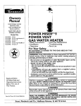
POWER
MISER !
O
GAS WATER
HEATER
• Safety Instructions
• Installation
• Operation
• Care and Maintenance
• Troubleshooting
• Parts List
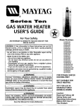
For Your Safety
AN ODORANT
IS ADDED
WATER HEATER
TO THE GAS USED
BY THIS
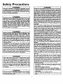
WARNING: If the information in these instructions are not fol"lowed exactly, a .fire or explosion may result, causing property
-damage, personal mlury or death.
-,,Do not store or use gas.oline or other flammable vapors and liquids in the vicinity of this or any other appliance.
-WHAT TO DO IF YOU SMELL GAS
-- : Do not try to light any appliance.
Do not touch any electrtcal switch; do not use any phone in your
building.
• Imme_ately
call your gas supplier from a neighbor's
phone.
Follow the gas supplier's]nstructions.
If you can not reach your gas supplier, call the fire department.
-Installation and service must be performed by a qualified installer,
service agency or the gas supplier.
Caution:
Read and Follow
•
AWARNING
]-
.
Improper installatmn, adjustment, alteration, service or mamtenancel
can cause DEATH, SERIOUS BODILY INJURY, OR PROPERTY DAM-|
AGE. Refer to th,s manual for assistance or consult the local Sears|
Service Center or gas utility for further information.
|
All Safety Rules and
Operating Instructions
Before First Use of
This Product.
_,WARNING
Flammable
vapors maybe
drawn
of the structure to this appliance•
Save this Manual for Future Reference.
Sears,
Roebuck
by air currents
from
_,WARNING
READ THE GENERAL SAFETY SECTION
BEGINNING
COVER AND THEN THIS ENTIRE MANUAL BEFORE
OR OPERATING THIS WATER HEATER.
and Co., Hoffman
Estates,
IL 60179
U.S.A.
other
areas
ON INSIDE
INSTALLING
Safety Precautions
•
_W,.ARNING
.
Impro.per installation, adjustment , alteration, service
or maintenance can cause DEATH, SERIOUS BODILY
INJURY, OR PROPERTY DAMAGE. Refer to this manuI al for assistance or consult your local Sears Service
[ Center for further information.
AWARNING
WATER HEATERS EQUIPPED FOR ONE TYPE GAS
ONLY: This water heater is equipped for one type gas
only. Check the model rating plate near the gas control
valve for the correct gas. DO NOT USE THIS WATER
HEATER WITH ANY GAS OTHER THAN THE ONE
SHOWN QN THE MODEL RATING PLATE. Failure to
usethe correct gascan causeproblem'swhich canresult in
DEATH, SERIOUS BODILY INJURY, OR PROPERTY
DAMAGE. If you have any questions or doubts consult
your gassupplieror localutility.
AWARNING
INSTALLATIONS IN AREAS WHERE FLAMMABLE LIQUIDS (VAPORS) ARE LIKELY TO BE PRESENT OR
STORED (GARAGES, STORAGE, AND UTILITY AREAS,
ETC): Flammable liquids (such as gasoline, solvents,
propane (LP) or butane, etc.), all of which emit flammable
vapors, may be improperly stored or used in such areas.
The gas water heater pilot light or main burner can ignite
such vapors. The resulting flashback and fire can cause
death or serious burns to anyone in the area, as well as
property damage.
If installation in such areas is your only option, then the
installation must be accomplishedin a way that the pilot
flame and main burner flame are elevated from the floor
at least 18 inches. While this may reduce the chancesof
flammable vapors from a floor spill being ignited, gasoline
and other flammable substancesshouldnever be stored or
used in the same room or area containing a gas water
heater or other open flame or spark producingappliance.
NOTE: Flammable vapors may be drawn by air currents
from other areasof the structure to the appliance.
AWARNING
If this water heater will be used in beauty shops, barber
shops, cleaning establishments, or self-service laundries
with dry cleaning equipment, it is imperative that the
water heater or water heaters be installed so that combustion and ventilation air be taken from outside these
areas. Refer to the "Facts to Consider About the
Location" section of this manual and also the latest edition of the National Fuel Gas Code, ANSI Z223.1, also
referred to as NFPA 54 for specificsprovided concerning
air required.
_.WARNING
]
A fire can start if co_Hals
such as clothing,|
cleaningmaterials, or flammable liquidsare placed against|
or next to the water heater.
/
_,WARNING
At the time of manufacture this water heater was provided with a combination temperature-pressures relief valve
certified by a nation.ally, recognized testing laboratory
that maintains penodlc inspection of production of listed
equipment or materials, as meeting the requirements for
Relief Valves and Automatic Gas Shutoff Devicesfor Hot
Water Supply Systems, and the latest edition of ANSI
Z21.22 and the code requirements of ASME. If replaced,
the valve must meet the requirements of local codes,but
not less than a combination temperature and pressure
relief valve certified as meeting the requirements for
Relief Valves and Automatic Gas Shutoff Devicesfor Hot
Water Supply Systems,ANSI Z21.22 by a nationally recognized testing laboratory that maintains periodic
inspection of production of listed equipment or
materials.
The valve must be marked with a maximum set pressure
not to exceed the marked hydrostatic working pressure
of the water heater (150 Ibs./sq. in.) and a discharge
capacity not less than the water heater input rate as
shown on the model rating plate. (Electric heaters watts divided by 1000 x 3415 equal BTU/Hr. rate.)
Your local jurisdictional authority, while mandating the
use of a temperature-prossure relief valve complying
with ANSI Z21.22 and ASME, may require a valve model
different from the one furnished with the water heater.
Compliance with such local requirements must be satisfied by the installer or end user of the water heater with
a locally prescribed temperature-pressure relief valve
installed in the designated opening in the water heater in
place of the factory furnished valve.
For safe operation of the water heater, the relief valve
must not b_ _OV---e'a'Trom_-'T_-'ed_g_aT_d_opening or
plugged...........................
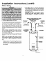
The temperature-pressure relief valve must be installed
directly into_he_fieein_f_the-weter heater designatedfor
the relief valve. Positionthe valve downward and provide
tubing so that any dischal_e-WHT_it only within 6 inches
above, or at any_dis.tancebe!ow the structural floor. Be
certain that no contact is made with any live electrical
part. The discharge.opening must not be blocked or
reduced in size under any circumstances. Excessive
length, over'30"feet,-or use of more than four elbows can
cause restriction and reduce the discharge capacity of
the valve.
No valve or other obstruction is to be placed between
the relief valve and the tank. Do not connect tubing
directly to dischargedrain unlessa 6 air gap is provided.
To prevent bodily injury, hazard to life, or property damage, the relief valve must be allowed to dischargewater
in quantities should circumstances demand• If the discharge pipe is not connected to a drain or other suitable
means, the water flow may causeproperty damage.
The Discharge Pipe:
Must not be smaller in size than the outlet pipe size of
the valve, or have any reducing couplings or other
restrictions.
Must not be pluggedor blocked.
Must be of material listed for hot water distribution.
Must be installed so as to allow complete drainage of
both the temperature-pressure relief valve, and the discharge pipe.
• Must terminate at an adequate drain.
• Must not have any valve between the relief valve and
tank.
?
Safety Precautions
_,WARNING
AWARNING
A gas water beater cannot operate properly without the
correct amount of air for combustion. Do not install in a
confined area such a closet, unless you provide air as
shown in the "Facts to Consider About the Location" section. Never obstruct the flow of ventilation air. If you have
any doubts or questions at all, call your gas company.
Failure to provide the proper amount of combustion air
can result in a fire or explosion and can cause DEATH
SERIOUS BODILY INJURY,OR PROPERTY DAMAGE.
This water heater must not be installed directly on carpeUng. Carpeting must be protected by a metal or wood
panel beneath the appliance extending beyond the full
width and depth of the appliance by at least 3 inches
(76.2mm) in any direction, or if the appliance is installed
in an alcove or closet,the entire floor must be covered b
the panel. Failure to heed this warning may result in i
fire hazard.
AWARNING
A, WARNING
VENT DAMPERS - Any vent damper, whether it is operat.
ed thermally or otherwise must be removed if its use
inhibitsproper drafting of the water heater.
Thermally Operated Vent Dampers: Gas-fired water
heaters having thermal efficiency in excess of 80% may
produce a relatively low flue gastemperature. Such temperatures may not be high enoughto properly open thermally operated vent dampers. This would causespillageof
flue gasesand may causecarbon monoxide poisoning.
Vent dampers must bear evidenceof certification as complying with the latest edition of American National
Standard ANSI Z21.68 (ANSI Z21.66 & 67, respectively,
cover electrically and mechanically actuated vent
dampers). Before installationof any vent damper, consult
your local Sears Service Center or the gas utility for further information.
HOTTER WATER CAN SCALD: Water heaters are
intended to produce hot water. Water heated to a tamperaturo which will satisfy clothes washing; dish washing,
and other sanitizing needs can scald and permanently
injure you upon contact. Some people are more likely to
be permanently injured by hot water than others. These
includethe eldedy, children, the infirm, or physically/mentally handicapped.If anyone usinghot water in your home
fits into one of these groups or if there is a local code or
state law requiring a certain temperature water at the hot
water tap, then you must take specialprecautions.In addition to usingthe lowest possibletemperature setting that
satisfiesyour hot water needs, a means such as a mixing
valve, shouldbe used at the hot water taps used by these
people or at the water heater. Mixing valvesare available
at plumbing supply or hardware stores. Follow manufacturers instructions for installation of the valves. Before
changingthe factory setting on the thermostat, read the
"Temperature Regulation" sectionin this manual.
_,WARNING
•The appliance and its individualshutoffvalvemust be disconnected from the gassupplypiping system during any
pressure testing of the gas system at test pressuresin
excessof ½ poundper squareinch (3.5kPa).
•The appliance must be isolatedfrom the gassupply piping system by closingits individual manual shutoffvalve
during any pressure testing of the gas supplypiping system at test pressuresequal or less than Y_pound per
squareinch (3.5kPa).
_,WARNING
Soot build-up indicates a problem that requires correction before further use. Turn "OFF" gas to water heater
and leave "OFF" until repairs are made, because failure
to correct the cause of the sooting can result in a fire or
explosion causing DEATH, SERIOUS BODILY INJURY,
OR PROPERTY DAMAGE.
_,WARNING
AWARNING
Chemical vapor corrosion of the flue and vent system
may occur if air for combustion contains certain chemical
vapors. Spray can propellants, cleaningsolvents,refrigerator and air conditioner refrigerants, swimming pool
chemicals, calcium and sodium chloride, waxes, bleach,
and process chemicals are typical compounds which are
potentially corrosive.
BEFORE LIGHTING [PROPANE (L.R) GAS WATER
HEATERS]: Propane (L.R) gas is heavier than air. Should
there be a leak in the system, the gaswill settle near the
ground. Basements, crawl spaces, skirted areas under
mobile homes (even when ventilated), closets and areas
below ground level will serve as pocketsfor the accumulation of this gas. Before attempting to light or relight the
water heater's pilot or turning on a nearby electrical light
switch, be absolutely sure there is no accumulated gas in
the ares Search for odor of gas by sniffingat ground level
in the vicinity of the appliance. If odor is detected, follow
steps indicated at "For Your Safety" on the cover page of
this manual then leavethe premises.
A, WARNING
i
Obstructed or deteriorated vent systems may present a
serioushealth risk or asphyxiation.
Safety Precautions continued on page 4
3
Safety Precautions
._,WARNING
ACAUTION
I
.....
WATER HEATERS EVENTUALLY LEAK: Installation of
the water heater must be accomplished in sucha manner
that if the tank or any connectionsshouldleak, the flow of
water will not causedamage to the structure. When such
locations cannot be avoided, a suitable drain pan should
be installed under the water heater, Drain pans are available at your local Sears store. Such a drain pan must be
not greater than 1% inchesdeep, have a minimum length
and width of at least 2 Inches greater than the water
heater dimensions and must be piped to an adequate
drain. The pan must not restrict combustion air' flow,
Under no circumstances is the manufacturer or Sears to
be held liable for any water damage in connection with
this water heater,
The water heater with draft hood installedmust be prep. [
erly vented to a chimney which termm.ates outdoors. I
Never operate the water heater unlessit is vented to the
outdoors and has adequate air supply.to avoid risks of
improper operation, explosionor asphyxiation.
AWARNING
Minimum clearancesbetween the water heater and combustibleconstruction are I" at the sidesand rear, 4" at the
front, and 6" from the vent pipe. Clearance from the top
of the jacket is 18" on most models. Note that a lesser
dimension may be allowed on some models. Refer to the
label on the water heater adjacent to the gascontrol valve
for all clearances.
.
&WARNING
[
Do not use this applianceif any part of.it has been under I
water. Immediately call a Sears Service Technician to [
inspectthe applianceand to replace the gascontrol or any
part of the burner systemwhich hasbeen under water.
_,WARNING
HYDROGEN GAS: Hydrogen gascan be produced in a hot
water system that has not been used for a long period of
time (generally two weeks or more). Hydrogen gas is
extremely flammable and explosive.To prevent the possibility of injury under these conditions,we recommend the
hot water faucet be opened for several minutes at the
kitchen sink before any electrical appliances which are
connectedto the hot water system are used(such as a dishwasher or washing machine). If hydrogen gas is present,
there will probably he an unusual sound similar to air
escaping through the pipe as the hot water faucet is
opened. There must be no smoking or open flame near
the faucnt at the time it is open.
a, WARNING
INSULATING JACKETS: When installing an external
water heater insulationjacket on a gaswater heater:
• DO NOT cover the temperature-pressure relief valve.
• DO NOT put insulation over any part of the top of the
gaswater heater,
• DO NOT put insulation over the gascontrol valve or gas
control valve/burner cover, or any access areas to the
burner.
• DO NOT let insulation around the gas water heater to
get within 8 inches of the floor (air must get to the
burner).
• DO NOT cover or remove operating instructions, and
safety related warning labelsand materials affixed to the
water heater.
Failure to heed this will result in the possibilityof a fire or
explosion.
4
Table of Contents
_c__oarety
Precautions .....................................................................................................
2_
Table of Contents .....................................................................................................
5
Customer Responsibilities ......................................................................................
6
Product Specincations .............................................................................................
6
Materials and Basic Tools Needed ........................................................................
7
Materials Needed ......................................................................................................................................................................
Basic Tools ................................................................................................................................................................................
7
7
Installation Instructions ..........................................................................................
g-_6
Removing the Old Water Heater ...............................................................................................................................................
Facts to Consider About the Location .......................................................................................................................................
8
9
Combustion Air and Ventilation for Appliances in Unconfined Spaces ...................................................................................
10
Combustion Air and Ventilation for Appliances in Confined Spaces .......................................................................................
10
Water Piping ...........................................................................................................................................................................
11
Temperature-Pressure Relief Valve................ _..........................................................................................................................
12
Filling the Water Heater ..........................................................................................................................................................
13
Venting ..............................................................................................................................................................................
13-14
Gas Piping ..........................................................................................................................................................................
14-15
Installation Checklist ..............................................................................................................................................................
16
Operatin_ Instructions ...........................................................................................
17-19
"'
Eighting
.............................................................................................................................................................................
_
Temperature Regulation ..........................................................................................................................................................
Service and Adjustment
......................................................................................................................
Taok (Sediment) Cleaning ......................................................................................................................................................
Venting System Inspection ......................................................................................................................................................
Burner Inspection ...................................................................................................................................................................
Burner Cleaning .....................................................................................................................................................................
Draining .................................................................................................................................................................................
Temperature-Pressure Relief Valve Operation ..........................................................................................................................
Drain ValveWasher Replacement ...........................................................................................................................................
Housekeeping .........................................................................................................................................................................
Service ....................................................................................................................................................................................
Troubleshooting
17-18
19
20-22
20
20
20
20
21
21
21
21
21
Guide ..........................................................................................
22-25
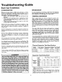
Start Up Conditions ...............................................................................................................................................................
Condensation .......................................................................................................................................................................
Smoke/Odor ............... ;.........................................................................................................................................................
Thermal Expansion .........................................................................................................................................................
Strange Sounds .....................................................................................................................................................................
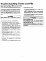
Operational Conditions .....................................................................................................................................................
Smelly Water .........................................................................................................................................................................
Air m Hot Water Faucets ...................................................................................................................................................
High Temperature Shut OffSysrem ......................................................................................................................................
Not Enough Hot Water ........................................................................................................................................................
Water is too Hot ...................................................................................................................................................................
LeakageCheckpoints ..............................................................................................................................................................
22
22
22
22-23
23
23-24
23
23
24
24
24
25
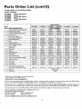
Parts Order List ........................................................................................................
26-27
Customer
Responsibilities
Thank You for
• This manual contains instructions for the installation, operation, and maintenance of the gas-fired water heater. It also
contains warnings through out the manual that you must read
and be aware of. All warnings and all instructions are essential
to the proper operation of the water heater and your safety.
Since we cannot put everything on the first few pages, READ
THE ENTIRE MANUAL BEFORE ATTEMPTING TO
INSTALL OR OPERATE THE WATER HEATER.
• The installation must conform with the instructions in this
manual; gas company rules; and Local Codes, or in the
absence of Local Codes, with the latest edition of the National
Fuel Gas code, ANSI Z223.1, also referred to as NFPA 54.
This publication is available from your local government or
public library or gas company or by writing NFPA,
Batterymarch Park,Quincy, MA 02269.
• If after reading this manualyou have any questions or do not
understand any portion of the instructions, call the Sears
Service Center.
• Carefully plan the place wheie you are going to put the water
heater. Correct combustion, vent action, and vent pipe installation are very important in preventing death from possible
carbon monoxide poisoning and fires.
Examine the location to ensure the water heater complies with
the "Facts to Consider about the Location" section in this
manual.
• For California installation this water heater must be braced,
anchored, or strapped to avoid falling or moving during an
earthquake. See instructions for correct installation procedures. Instructions may be obtained from your local dealer,
wholesaler, public utilities or California Office of the State
Architect, 400 P Street, Sacramento, CA 95814.
purchasinga
Sears water heater.
Properly installed and maintained, it should give you years of
trouble free service. If you should decide that you want the new
water heater professionally installed by Sears call the local Sears
Service Center or any Sears store. They will arrange for prompt,
quality installation by Sears authorized contractors.
.
Abbreviations Found In This ImtrucUon Manual
A.G.A. - American Gas Association
A.N.S.I. - American National Standards Institute
N.EP.A. - National Fire Protection Agency
AWARNING
This gas-fired water beater is design certified by the
American Gas Association Laboratories under American
National Standards for Gas Water Heaters. The installation must conform with this manual, Local Codesand with
the latest edition of the National Fuel Gas Code, ANSI
Z223.1.:
This publicationis availablefrom your localgovernmentor
public library, gas company, or by writing NFPA,
Batterymarch Park, Quincy,MA 02269.
• Read the "Safety Precautions" section, pages 2 through 4 of
this manual first and then the entire manual carefully. If you
don't follow the safety rules, the water heater will not operate
properly. It could cause DEATH, SERIOUS BODILY
INJURYAND/OR PROPERTY DAMAGE.
Product Specifications
DIMENSIONS IN INCHES
MODEL
NUMBER
TANK
CAPACITY
IN _NS
TYPE
OF
GAS
B.T.U.
RATE
RECOVERY RATE
GALS. PER HOUR
@90°F RISE
MINIMUM
VENT
PIPE
DIAMETER
153.330401
40
NATURAL
40,000
46.0
3" or4"
18"
60"
153.330451
153.330501
40
NATURAL
40,000
46.0
3" or 4"
18"
60"
50
NATURAL
40,000
46.0
3" or 4"
20"
59½"
153.330551
50
NATURAL
40,000
46.0
3" or4"
20"
59½"
153.330701
75
NATURAL
55,000
59.2
4"
24"
60"
153.330751
75
NATURAL
55,000
59.2
4"
24"
60"
HEIGHT TO
JACKET TOP
Materials
Materials
and Basic Tools Needed
Needed
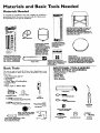
To simplify the installation Sears has available the installation
parts shown below. You may or may not need all of these materials, depending on your type of installation.
WATER HEATER STAND 24"x24"x 18"
FOR USE WITH WATER HEATERS
INSTALLED IN RESIDENTIAL
GARAGES HAVING A DIAMETER 24"
OR LESS AND A RATED CAPACITY 75
GALLONS OR LESS
i Water Heater
Installation
Kit
VENT
ELBOW
_.
EXPANSION
TANKS
FOR THERMAL
EXPANSION
CONDITIONS AVAILABLE IN
2 GALLON AND 5
GALLON CAPACITY
THROUGH
LOCAL
SEARS STORE OR
SERVICE CENTERS
WATER HEATER INSTALLATION KIT WITH FLEXIBLE CONNECTORS
FOR
314" OR 112" THREADED
OR COPPER PLUMBING
DRAIN PANS
f
VENT
WATER HEATER HEAT
TRAPS HELP REDUCE HEAT
LOSS DUE TO THERMAL
SYPHONING
PIPE
Basic Tools
AVAILABLE
IN 20" HAVING
DIAMETER
FOR
WATER
HEATERS
A DIAMETER 18" OR LESS AND AVAILABLE IN
28" DIAMETER FOR WATER HEATERS
HAVING A DIAMETER 26" OR LESS
ADDITIONAL
TOOLS NEEDED
WHEN SWEAT SOLDERING
You may or may not need all of these tools, depending on ycour
type of installation. These tools can be purchased at your local
Sears store.
•
•
•
•
•
•
•
FLEXIBLE WATER
HEATER GAS CONNECTOR WITH
FITTINGS
Pipe Wrenches (2) 14"
Screwdriver
Tin Snips
6 Foot Tape of Folding Rule
Garden Hose
Drill
Pipe dope or Teflon Tape
•
•
•
•
•
•
Tubing Cutters or Hacksaw
Propane Torch
Soft Solder
Solder Flux
Emery Cloth
Wire Brushes
HACKSAW
GARDEN
HOSE
6 FOOT
TAPE
j
SLOT-HEAD
PIPE
WRENCH
314" WIRE BRUSH
SCREWDRIVER
I/2" WIRE BRUSH
PHILLIPS
SCREWDRIVER
PROPANE
TORCH
TIN SNIPS
ROLL OF LEAD FREE
SOFT SOLDER
ROLL OF TEFLON TAPE
(USE ONLY ON WATER
CONNECTIONS)
PIPE DOPE (SQUEEZE TUBE)
(USE FOR WATER AND
GAS CONNECTIONS)
DRILL
ROLL OF EMERY
CLOTH
SOLDER FLUX
TUBING
CUTTER
?
Installation
Instructions
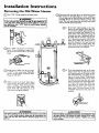
Removing the Old Water Heater
Turn "OFF"
the gas supply to the water heater.
AWARNING
o
If the main gas line shutoff serving all _
appliances is
used, also shut "OFF" the gas at each appliance. Leave all
gas appliances shut "OFF" until the water heater installa-
('_Disconnect
the vent pipe from the draft hood where
they connect to the water heater. In most installations
the vent pipe can be lifted offafter any screw or other
attached devices are removed. Dispose of the draft
hood. The new water heater has the draft hood which
must be used for proper operation.
®
t on s comp ete.
®
®
the water to the water
Turn "OFF"
heater. Some installations
require that
the water be turned off to the entire
house.
Check again to make sure the gas supply
is "OFF" to the water heater. Then disconnect the gas supply connection from
the gas control valve.
Q
Attach a hose to the water heater drain
valve and put the other end in a floor
drain or outdoors. Open the water heater
drain valve. Open a nearby hot water
faucet which will relieve pressure in the
water heater and speed draining.
AWARNING
]
The water passingou_ve
may be extremely ]
hot. To avoid being scalded make sure all connectionsare |
tight and that the water flow is directed away from anyI
person,
i
J
Q
a.
If you have copper piping to the water
heater, the two copper water pipes can
be cut with a hacksaw approximately 4"
away from where they connect to the
water heater. This will avoid cutting off
the pipes too short. Additional cuts can
be made later if necessary. Disconnect
the temperature-pressure
relief valve
drain line. When the water heater is
drained, disconnect the hose from the
drain valve. Close the drain valve. The
water heater is now completely disconnected and ready to be removed.
b. If you have galvanized pipe to the water
heater, loosen the two galvanized pipes
with a pipe wrench at the union in each
line. Also disconnect the piping remaining to the water heater. These pieces
should be saved since they may be needed when recofinecting
the new water
heater. Disconnect the temperature-pressure relief valve drain line. When the
water heater is drained, disconnect the
hose from the drain valve. Close the
drain valve. The water heater is now
completely disconnected and ready to be
removed.
A CAUTION
J
Mineral buildup or sediment may have accumulated in the J
old water heater. This causes the water heater to be much
heavier than normal and this residue, if spilled out, could
cause staining.
Installation
Instructions
Facts to Consider
Location
About the
You should carefully choose an indoor location for the new
water heater, because the placement is a very important consideration for the safety of the occupants in the building and for
the most economical use of the appliance. This water heater is
not for use in mobile homes or outdoor installation.
Whether
replacing an old water heater or putting the water
heater in a new location, the following critical points must be
observed.
The location selected should be indoors as close as practical
to the gas vent or chimney to which the water heater vent is
going to be connected, and as centralized with the water piping system as possible. The water heater, as all water heaters,
will eventually leak. Do not install without adequate
drainage provisions where water flow will cause damage.
A CAUTION
WATER HEATERS EVENTUALLY LEAK: Installationof the
water heater must be accomplishedin sucha mannerthat if
the tank or any connectionsshouldleak, the flow of water will
not causedamageto the structure.When suchlocationscannot be avoided,a suitable drain pan shouldbe installedunder
the water heater.Drain pansare availableat your localSears
store. Such a drain pan must be not greater than 1½ inches
deep,have a minimum length and width of at least 2 inches
greater than the water heater dimensionsand must be piped
to an adequatedrain.The pan mustnot restrictcombustionair
flow.Under no circumstances
isthe manufactureror Searsto
be held liable for any water damage in connectionwith this
water heater.
(cont'd)
• The location selection must provide adequate clearances for servicing and properoperation of the waterheater.
AWARNING
This water heater must not be installeddirectlyon carpeting.
Carpeting must be protected by a metal or wood panel
beneath the appliance extendingbeyondthe full width and
depth of the appliance by at least 3 inches(76.2mm) in any
direction,or if the appliance isinstalledin an alcoveor closet,
the entire floor mustbe coveredbythe panel.Failureto heed
this warningmay result.ina fire hazard.
AWARNING
Minimum clearancesbetween the water heater and combnstibleconstructionare I" at the sidesand rear, 4" at the
front, and 6"from thevent pipe.Clearancefrom the top of the
jacketis 18"on mostmodelgNote that a lesserdimensionmay
be allowed on somemodels.Refer to the label on the water
heateradjacent to the gascontrolvalvefor all dearances.
12"MA_
t
VEN'rILATION
AIR
OPENINGS O
+
_"
AWARNING
INSTALLATIONSIN AREASWHERE FLAMMABLELIQUIDS
VAPORS) ARE LIKELY TO BE PRESENT OR STORED
(GARAGES, STORAGE, AND UTILITY AREAS, ETC):
Flammableliquids(suchasgasoline,solvents,propane(LP) or
butane, etc.), all of which emit flammable vapors, may be
improperlystoredor usedin suchareas.The gaswater heater
pilot lightor main burnercan ignitesuchvapors.The resulting
flashback
and Erecancausedeathor seriousbumsto anyonein
the area,aswellaspmpertydamage.
If installationin suchareasis youronlyoption,then the installation must be accomplishedin a way that the pilot flame and
main burnerflameare elevatedfrom the floorat least18 incheg
While this may reducethe chancesof flammablevaporsfrom a
floorspillbeingignited,gasolineand otherflammablesubstances
shouldnever be stored or usedin the sameroom or area containinga gaswater heater or other openflameor sparkproducingappliance.
NOTE: Flammablevaporsmay be drawnby air currentsfrom
otherareasof the structureto the appliance.
AWARNING
Propellantsof aerosolspraysand volatilecompounds,(cleaners,chlorinebasedchemicals,refrigerants, etc.) in additionto
being highlyflammable in manycases,will alsochangeto corrosive hydrochloricacid when exposedto the combustion
,roducts of the water heater.The results can be hazardous,
_d alsocauseproductfailure.
FRONT VIE'vV
OF DOOR
OF CLOSET
WITHOUT
DOOR
MAX.
TOP VIEW I" NIN.
OF CLOSET
WITH DOOR
AIR DUCT
Figure I ]
AWARNING
A gaswater heater cannotoperate properlywithout the correct amount of air for combustion.Do not installin a confined
area sucha doset,unlessyou provideair asshowninthe "Facts
to Considerabout the Location"section.Never obstructthe
flow ofventilationair. If you haveanydoubtsor questions
at all,
callyourgascompany.Failureto providethe properamount of
combustionair can resultin a fire or explosionand cancause
DEATH,SERIOUSBODILYINJUR_,ORPROPERTYDAMAGE.
AWARNING
If this water heater will be usedin beauty shops,barbershops,
cleaning establishments,or self-servicelaundrieswith dry
cleaningequipment, it is imperativethat the water heater or
water heatersbe installedso that combustionand ventilation
air be taken from outsidetheseareag Refer to the "Facts to
ConsiderAbout the Location"sectionof this manual and also
the latestedition of the NationalFuelGas Code,ANSI Z223.1
also referredto as NFPA 54 for specifics
providedconcernin
air required.
Installation
InStructions (cont'd)
Combustion Air and Ventilation
for Appliances Located in
Unconfined Spaces
Uncon_qned Space is a space whose volume is not less than 50
cubic feet per 1,000 Btu per hour of the aggregate input rating
of all appliances installed in that space. Rooms comuiunicatin_
directly with the space in which the appliances are installed,
through openings not furnished with doors, are considered a
part of the unconfined space
In unconfined spaces in buildings, infiltration may be adequate
to provide air for combustion, ventilation and dilution of flue
gases. However, in buildings of tight construction (for example,
weather stripping, heavily insulated, caulked, vapor barrier, etc.),
additional air may need to be provided using the methods
described in Comb.ustion Air and Ventilation_ for Appliances
Located in Confined Spaces, b.
1. When directly communicating with the outdoolS, each opening shall have a minimum free area of 1 square inch per 4,000
BTU per hour of total input rating of all equipment in the
enclosure. (See Figure 3.)
2. When communicating with the outdoors through vertical
ducts, each opening shall have a minimum free area of 1
square inch per 4,000 BTU per hour of total input rating of
all equipment in the enclosure. (See Figure4.)
• CHIMNEY O_ _
VENT
Combustion Air and Ventilation
for Appliances Located in
Confined Spaces
Confined Space is a space whose volume is less than 50 cubic
feet per 1,000 Btu per hour of the aggregateinput rating of all
appliances installed in that space.
a. ALL AIR FROM INSIDE BUILDINGS:
(See Page 9 Figure 1, and Figure 2 below)
The confined space shall be provided with two permanent
openings communicating directly with an additional room(s)
of sufficient volume so that the combined volume of all
spaces meets the criteria for an unconfined space. The total
input of all gas utilization equipment installed in the combined space shall be considered in making this determination.
Each opening shall have a minimum free area of one square
inch per 1,000 BTU per hour of the total input rating of all
gas utilization equipment in the confined space, but not less
than 100 square inches. One opening shall commence within
12" of the top and one commencing within 12" of the bottom of the enclosure.
I Figure 4 ]
3. When communicating with the outdoors through horizontal
ducts, each opening shall have a minimum free area of 1
square inch per 2,000 BTU per hour of total input rating of
all equipment in the enclosure. (See Figure 5.)
4. When ducts are
area as the free
The minimum
shall not be less
b. ALL AIR FROM OUTDOORS:
(see Figures 3-5)
The confined space shall be provided with two permanent
openings, one commencing within 12" of the top and one
commencing within 12" from the bottom of the enclosure.
The openings shall communicate directly, or by ducts, with
the outdoors or spaces (crawl or attic) that freely communicate with the outdoors.
I Figure
.
3 1
10
used, they shall be of the same cross-sectional
area of the openings to which they connect.
short side dimension of rectangular air ducts
than 3". (See Figure 5.)
Louvers and Grilles: In calculating free area, consideration
shall be given to the blocking effect of louvers, grilles or
screens protecting openings. Screens used shall not be smaller
than ¼" mesh. If the free area through a design of louver or
grille is known, it should be used in calculating the size opening required to provide the free area specified. If the design
and free area is not known, it may be assumed that wood louvers will be 20-25 percent free area and metal louvers and
grilles will have 60-75 percent free area. Louvers and grilles
shall be fixed in the open position or interlocked
with the
equipment
so that they are opened automatically
during
equipment operation.
6. Special Conditions
Created by Mechanical Exhausting
or
Fireplaces: Operation
of exhaust fans, ventilation
systems,
clothes dryers or fireplaces may create conditions requiring
special attention to avoid unsatisfactory operation of installed
gas utilization equipment.
Installation
Water
Instructions
(cont'd)
Piping
•
AWARNING
HOTTERWATER CAN SCALD:.Water heatersam intendedto
producehot water. Water _
to a temperaturewhichwill
sat_fyclotheswashing,dishwashing,andother sanitizingneeds
canscaldand permanentlyinjureyou uponcontact.Some peo-I
pie aremore likelyto be permanentlyinjured byhot waterthan
others.Theseincludeth_ elder_ cin_lren,the infirm,or physically/mentallyhandicapped.
If anyoneusinghot waterin your home
Etsintooneofthesegroupsor ifthere isa localcodeor stateI_v
reclulrlng
a certaintemperature water at the hot water_ then
youmusttake specialprecaution_In additionto usingthe lowest
possible
temperaturesettingthat satisfiesyour hot water needs,
a meanssuchasa mixingvalve,shouldbe usedat the hotwater
tapsusedby thesepeopleor at the water heater.Mixingvalves
areavailableat plumbingsupplyor hardwarestore_ Followman.
ufacturers instructionsfor installationof the valves.Before
changingthe factory setting on the thermostat, read the
"Temperature Regulation"sectioninthis manual.
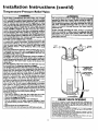
Look at the top cover of the water heater. The cold water
inlet is marked-cold. Put two or three turns of teflon tape
around the threaded end of the threaded-to-sweat coupling
and around both ends of the 3A"threaded nipple. Using flexible connectors, connect the cold water pipe to the coldwater
inlet of the water heater.
NOTE: This water heater is super insulated to minimize
heat loss from the tank. Further reductmn in heat loss
can be accomplished
by insulating
the hot water lines
from the water heater.
INSTALLATION
COMPLETED USING
"
SEARS INSTALLATION
KIT
This water heater shall not be connected to any heating systems or
component(s) used with a non-potable water beating appliance.
If a water heater is installed in a closed water supply system;
such as one having a back-flow preventer, check valve, water
meter with a check valve, etc.., in the cold water supply; means
shall be provided to control thermal expansion. Contact the
local utility or local Sears Service Center on how to control this
situation,
NOTE: To _protect against untimely corrosion of hot and
cold water fittings, it is strongly recommended that dl-electric unions or couplings be installed on this water heater
when connected to copper pipe.
FLEXIBLE WATER
CONNECTORS
HOT OUTLET
TO HOUSE
I
COLD INLET
WATER LINE
lg3
THREADED TO
SWEAT COUPLING
THREADED TO
SWEAT COUPLING
HEAT TRAP WITH
SECONDARY
IolA
_
I
_
]
_
314" THREADED
HEAT TRAp
ANODE
The illustration shows the attachment of the water piping to the
water heater. The water heater is equipped with ¾" water connections.
NOTE: If using copper tubing, solder tubing to an adapter
before attaching the adapter to the cold water inlet connection. Do not solder the cold water supply line directly to the
cold water inlet. It will harm the dip tube and damage the
tank.
•
--TEIqPERATUREPRESSURE
RELIEF VALVE
Look at the top cover of the water heater. The water outlet is
marked hot. Put two or three turns of teflon tape around the
threaded end of the threaded-to-sweat
coupling and around
both ends of the _A" threaded nipple. Using flexible connectors, connect the hot water pipe to the hot water outlet on
the water heater.
DISCHARGE
PIPE (Do not
cap or plug)
--6"
FLOOR DRAIN
11
AIR GAP
Installation
InstruCtions (cont'd)
Temperature-Pressure Relief Valve
A WARNING
&WARNING
At the time of manufacturethis water heater was provided
with a combinationtemperature-pressures
reliefvalvecertified
by a nationallyrecognizedtesting laboratorythat maintains
periodic mspec_onof productionof listedequipmentor materials, as meeting the requirements for Relief Valves and
AutomaticGasShutoffDevicesfor Hot Water SupplySystems,
and the latest edition of ANSI Z21.22 and the code requiremeritsof ASME.If replaced,the valvemustmeet the requirementsoflocalcodes,but not lessthan a combinationtemperature and pressurereliefvalvecertifiedas meetingthe requirements for ReliefValvesandAutomatic GasShutoffDevicesfor
Hot Water SupplySystems,ANSI Z21.22bya nationally recognized testinglaboratorythat maintainsperiodicinspectionof
productionof listedequipmentor material_
The valvemust be marked wit(1a maximum set pressurenot
to exceed the marked hydrostaticworking pressureof the
water heater (150 IbsJsq.in.) and a dischargecapacitynot less
than the water heater input rate asshownon the modelrating
plate. (Electric heaters - watts dividedby 1000 x 3415 equal
BTU/Hr. rate.)
Yourlocaljurisdictionalauthority,whilemandating the useof a
temperature-pressure
relief valvecomplyingwith ANSI Z21.22
and ASME, may requirea valvemodeldifferentfrom the one
furnishedwith the water heater.
Compliancewith suchlocal requirementsmustbe satisfiedby
the installeror enduser of the water heaterwith a locallyprescribedtemperature-pressure
reliefvalveinstalledin the designated openingin the water heater in placeof the factory furnishedvalve.
Forsafeoperationof the water heater,the relief valvemustnot
be removed from it'sdesignatedopeningor plugged.
The temperature-pressure
relief valvemust be installeddirectly
intothefittingofthe water heaterdesignated
for the reliefvalve.
Positionthe valvedownwardand providetubingsothat anydischargewill exit onlywithin 6 inchesabove,or at anydistance
belowthe structuralfloor. Be certainthat no contactis made
with any liveelectricalpart.The dischargeopeningmustnot be
blockedor reduced in sizeunder any circumstances.
Excessive
length,over 30 feet, or useof more than fourelbowscancause
restriction andreducethedischarge
capacityofthevalve.
No valveor otherobstructionisto be placedbetweenthe relief
valveand the tank. Do not connecttubingdi_ctly to discharge
drainunless
a 6"air gapisprovided.To preventbodilyinjury,hazard to life,or propertydamage,the relief valvemust be allowed
to discharge
waterin quantitiesshouldcircumstances
demand.If
the discharge
pipeis not connectedto a drainor other suitable
means,the waterflowmaycausepropertydamage.
The DischargePipe:
• Must not be smallerin size than the outlet pipesize of the
valve,or haveanyreducing couplings
or other restrlction_
• Mustnot bepluggedor blocked.
Mustbeof materiallistedfor hot waterdistribution.
Must be installedso as to allowcompletedrainageof both
the temperature-pressure relief valve, and the discharge
pipe.
Mustterminateat an adequatedrain.
Mustnot haveanyvalvebetweenthe reliefvalvaand tank.
The temperature-pressure relief valve must be manually
operated at least once a year. Caution shouldbe taken to
ensurethat (I) no one is in front of or aroundthe outlet of
the temperature-pressure reliefvalvedischargeline, and (2)
the water manually dischargedwill not cause any bodily
injury or property damage because the water may be
extremely hot.
ff after manually operating the valve, it fails.to completely
reset and continuesto release watar, immedmately
closethe
cold water inlet to the water heater, follow the draining
instructions,and replace the temperature-pressure relief
valvewith a new one.
HOT
COLD
SHUT OFF
VALVE
)_
PRESSURE
RELIEF VALVE
PIPE (Do not cap
or plug)
FLOOR DRAIN
RELIEFVALVEOPENING
At the timeof manufacture,this waterheaterwasprovided
with a combination
temperature-pressure
relief valvelistedascomplying
with the standard
for relief valves
andautomaticgasshut-offdevicesfor hot water supplysystems,
ANSI Z2}.22.For
safeoperation of the water heater,the relief valve must not be removed from its des-
Fgnated
pointofinstallation
or plugged.
Your localiurisdictional authority, while mandating the use of a temperature-pressure
relief valve complyingwith ANSI Z21.22 andASME, may require a valve model different from the one furnished with the water heater
Compliancewith suchlocal requirementsmust be satisfied by the instalieror end user
of the water heater with a locally prescribed temperature-pressure relief valve
instaJledin the designatedopeningin the water heater
See manual heading-"Temperature-Pressure Relief Valves"for installationand maintenance of relief valve, dischargeline, and other safety precautions.
]2
Installation
Filling the Water
Instructions
Heater
ACAUTION
For proper venting in certain installations, a largerdiameter vent
pipe may be necessary. Due to great variances in installations,
un-foreseeable by the manufacturer of the water heater, you must
consult your gas company to aid you in determining the proper
venting for your water heater from the vent tables in the latest
edition of the National Fuel Gas Code ANSI Z223.1, also
referred to as NFPA 54.
I
Never usethis water heat_' unlessit mcompletelyfilledwith I
wa_. To_ont
(cont'd)
dam_eto thetank,thetankmustbeelk_ I
with water. Water must flow from the hot water faucet
beforeturning "ON" gasto the water hea_.
To fill the water heater with water:
• Close the water heater drain valve by turning the handle to
the right (clockwise). The drain valve is on the lower front of
the water heater.
Open the cold water supply valve to the water heater.
NOTE: The cold water supply valve must be left open
when the water heater is in use.
To insure complete filling of the tank, allow air ro exit by
opening the nearest hot water faucet. Allow water to run
until a constant flow is obtained. This will let air out of the
water heater and the piping.
Check all new water piping for leaks. Repairas needed.
Check the venting system for signs of obstruction or deterioration and replace if needed.
The combustion and ventilation air flow must not be obstructed.
,
AWARNING
Ob .structedor deterioratedventsystemsmaypresenta serious
I healthrisk or asphyxiation.
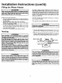
• Place the draft hood legs in the receiving holes on the top of
the water heater. The legs will snap in the holes to give a tight
fit.
• Place the vent pi.pe over the draft hood. With the vent pipe in
position, drill a small hole through both the vent pipe and
draft hood. Secure them together with a sheet metal screw.
Venting
_E,WARNING
VENT DAMPERS- Any vent damper, whether it is operated
thermally or otherwisemustbe remom_lif itsuseinhibitsproper draftingof the waterheater.
Thermally Operated Vent Damper_ Gas-firedwater heaters
havingthermal efEciencyin excessof 80%may producea rein.
tively lowfluegastemperature.Suchtemperaturesmaynot be
high enough to properly open thermally operated vent
damper_Thiswouldcausespillageof Iluegasesand maycause
carbonmonoxidepoisoning.
Vent dampersmust bear evidenceof certificationascomplying
with the latestedition of American National StandardANSI
Z21.68 (ANSI 7.21.66& 67, respectively,
coverelectricallyand
mechanicallyactuatedvent dampers).Beforeinstallationof any
ventdamper,consultyourlocalSearsServiceCenteror thegas
utilityfor further information.
DRAFT
HOOD
,
t
_VEN T,,,,]
ISCREV¢____I
DRAFTHOOD
_
DRAFT
HO_
TNTOOUTDOORS
OR
AWARNING
The water heater wit_lled
must be properlyI
vented to a chimneywhichterminatesoutdoors.Never operate the water heater unlessit isventedto the outdoorsand has
adequateair supplyto avoidrisksof improperoperation,explosionor esphyxiation.
[
AWARNING
To insure proper venting of this gas-firedwater heater, the
correctventpipe diameter must be utilized.Any additionsor
deletions of other gasapplianceson a commonvent with this
water heater may adverselyaffectthe operationof the water
heater.Consultthe localSearsServiceCenter or gasutility if
anysuchchangesare planned.
AWARNING
[
The vent pipefrom the water heater mustbe no lessthan the I
diameter of the draft hoed outlet on the water heater, and
must slopeupwardto the chimneyat least'/4inchper linear
foot
13
Installation
Instructions
(cont'd)
Gas Piping
Venting (cont'd)
All vent gases must be completdy vented to the outdoors of the
structure (dwelling). InstaU only the draft hood provided with
the new water heater and no other draft hood.
Vent pipes must be secured at each joint with sheet metal screws.
AWARNING
Make sore the gas suppliedis the same type listed on the
model rating plate. The inlet gas pressuremust not exceed
14 incheswater column ½ pound per squareinch(3.SkPa).
The minimum inlet gaspressurelisted on the model ratin
plate isfor the purposeofinput adj_
TO
CHIMNEY
AW.A.RNING
[
If the gascontrolvalveis subjectedto pressuresexceeding ½[
pound per square inch(3.SkPa),the damageto the gascon-[
VENT PIPE INSTALLATION
[ trel valvecouldresultin a Ere or explosionfrom leakingga_
There must be a minimfim of 6" clearance between single wall
vent pipe and any combustible material. Fill and seal any clearance between single wall vent pipe and combustible material
with mortar mix, cement, or other noncombustible substance.
For other than single wall, follow vent pipe manufacturer's dearance specifications. To insure a tight fit of the vent pipe in a
brick chimney, seal around the vent pipe with mortar mix
AWARNING
[
If the main gasline shutoffservingall gasappliancesis used,[
alsoturn "OFF" the gasat eachappliance.Leaveall gasappliancesshutoff untilthe water heater installationiscomplete.
cement.
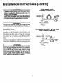
A gas line of sufficient size must be run to the water heater.
Consult the latest edition of National Fuel Gas Code ANSI
Z223.1, also referred to as NFPA54 and the gascompany concerning pipe size.
AWARNING
Failureto haverequired clearancesbetweenvent pipingand
combustiblematerial will resultin afire hazard.
There must be:
• A readily accessible manual shut offvalve in the gas supply line
serving the water heater, and
• A drip leg (sediment trap) ahead of the gas control valve to help
prevent dirt and foreign materials from entering the gas control
AWARNING
[
Be sure vent pipe is properlyconnectedto preventescapeof
dangerousflue gaseswhichcoud causedeadlyasphyxation.
valve.
• A flexible gas connector or a ground joint union between the
shutoffvalve and control valve to permit servicing of the unit.
Be sure to check all the gas piping for leaks before lighting the
water heater. Use a soapy water solution, not a match or open
flame. Rinse offsoapy solution and wipe dry.
AWARNING
Chemical vapor corrosionof the flue and vent system may
occurif air for combustioncontainscertain chemicalvapors.
Spray can propellants,cleaningsolvents,refrigerator and air
conditioner refrigerants, swimmingpool chemicals,calcium
and sodiumchloride,waxes,bleach,and processchemicalsare
typicalcompounds
whicharepotentially corrosive.
Standard Models are for installation up to 3,300 feet above sea
level.
High Altitude Models are for installation from 3,300 to 5,500
feet above sea level.
Ifa standard model is installed above 3,300 feet or a high altitude
model is installed above 5,500 feet, the input rating must be
reduced at the rate of 4 percent for each 1,000 feet above sea level.
Contact your local Sears Service Center or gas utility for forther
information.
AWARNING
The appliance and its gas connection must be leak tested
beforeplacngthe appliancein operation.
14
Installation
Instructions
(cont'd)
GAS PIPING WITH
FLEXIBLE CONNECTOR
AWARNING
• The applianceand itsindividualshutoffvalvemustbe disconnectedfrom the gassupplypiplng systemduringanypressure
testing of the gassystem at test pressuresin excessof
poundpersquare
inch(3.SkPa).
..
LOOP
• The appiiancemustbe isulatedfrom the gassuppiyIxl_ngsystem bydosingi_ individualmanualshutoff valveduringany
pressuretestingof the gassupplypipingsystemat trot pressuresequalor lessthan _ poundper squareinch(3.SkPa).
GAS
_'ONTROL
VALVE
GROUND
DRIP LEG
(Sedimenttrap)
AWARNING
[
Use pipe joint compound or teflon tape marked as being [
resistantto the acUonof petroleum [Propane(LR)] gase_ [
SEDIMENT
CAP
GAS PIPING WITH ALL BLACK
PIPE TO GAS CONTROL
TRAP
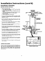
A sediment trap shall be installed as close to the inlet of the
water heater as practical at the time of water heater installation.
The sediment trap shall be either a tee fitting with a capped nipple in the bottom outlet or other device recognized as an effective sediment trap. Ifa tee fitting is used, it shall be installed in
conformance with one of the methods of installation shown
below.
GROUND JOINT "_
IRON
BLACK PIPE
GAS
CONTROL
VALVE
Connecting the gas piping to the gas control valve of the water
heater can be accomplished by either of the two methods shown.
3 min._
AWARNING
Contaminantsin the gaslinesmay causeimproper operation
of the gascontrolvalve that may resultin fire or explosion.
Beforeattachingthe gasline be sure that all gaspipeisclean
on the inside.To trap any dirt or foreign material in the gas
supplyline, a drip leg (sometimes called a sediment trap)
must be incorporated in the piping. The drip leg must be
readily accessible.Installin accordancewith the "Gas Piping"
section.Refer to the latest edition of the National Fuel Gas
Code, ANSI 7.223.1,also referred to as NFPA 54.
15
(Se_D'RmIPntLEt_ap)t
j CAP
Installation
Instructions
(cont'd)
Installation Checklist
BEFORE LIGHTING
THE PILOT:
Check the gas lines for leaks.
a. Use a soapy water solution. DO NOT test for gas leaks
usinga match or open flame.
b. Brush the soapy water solution on all gas pipes, joints and
fittings.
c. Check for bubbling soap. This means you have a leak.
Turn OFF _ gas andmake the necessary repairs.
d. Recheck for leaks.
e. Rinse offsoapy solution and wipe dry.
VENT PIPE TO
OUTDOORS
OR CHIMNEY
HOT
COLD
SHUTOFF VALVE
UNION
HOT-
• COLD
Is the new temperature-pressure relief v_ve properly installed
and piped to an adequate drain? See Temperature-Pressure
Relief Valve section.
2
• Are the cold and hot water lines'connected to the water
heater correctly? See "Water Pip_ng" instructions in the
c
.
Installat . on Instruct . ons . section.
PRESSURE
RELIEF VALVE
GAS SUPPLY
• Is the water heatercompletely filled with water? See _Filling"
instructions in the Installation Instructions.
• Will a water leak damage anything?
Consider About the Location section.
DISCHARGE PIPE
(Do not cap or plug)
See the "Facts to
SHUTOFF
VALVE
• Is there proper clearance between the water heater and anything that m!ght catch fire?See the "Facts to Consider About
the Location section.
TEE,
DRIP LEG
• Do you have adequate ventilation so that the water heater
will operate properly? See _Corabustion Air and Ventilation"
in the "Facts to Consider About the Location" section,
DRAIN VALVE
TRAP)
PIPE CAP
6 INCH AIR GAP
•
Is the draft hood vent piping properly secured? See _Venting"
instructions in the "Installation Instructions" section.
•
Is there proper clearance between the vent pipe and anything
that might catch on fire? See "Venting" instructions
in the
"Installation Instructions" section.
"
•
Is the vent pipeproperty
sloped and does the vent terminate
outdoors?
See "Venting"
instructions
in the "Installation
Instructions" section.
FLOOR DRAIN
• Do you need to call your gas company to check the gas pipe
and its hookup?
CHECK
FOR LEAKS
Be sure to check all your gas pipes for leaks before lighting your
water heater. Use a soapy water solution, not a match or open
flame. Check the factory gas fittings after pilot is lit and gas control knob is still in "PILOT" position. Then, check the fittings
when the main burner is turned "ON". Use a soapy water solution for this, too.
MODEL RATING PLATE
16
Operating
Instructions
Lighting
AWARNING
BEFORELIGHTING PROPANE(L.R)GAS WATER HEATERS:
Propane(LR) gasis beevierthan air. Shouldti_re be a le_k in
the system,the gaswill settle near the ground.Basements,
crawl spaces,skirtedareas under mobile homes (evenwhen
ventilated),closetsand areasbelowgroundlevelwill serveas
pocketsfor the accumulationof this 8_ Beforeat_emFdngto
light or mlight the water heater'spilot or turningon a nearby
electricaJlightswitch, be abeolutelysum there isno accumulated gasin the are_ Searchfor odor of gasby mimngst ground
level in the vicinityof the appliance.If odor is detected,follow
stepsindicatedat "For YourSafety"on the coverpageofthis
manualthenleavethe premise_
I Figure 6 ]
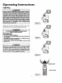
Lighting and operating instructions are located on front of the
water heater, above or to one side of the gas control valve.
AWARNING
AN ODORANT IS ADDED TO THE GAS USED
BY THIS WATER HEATER.
FOR YOUR SAFETY
IF YOU SMELLGAS:
Do not try to lightany appliance.
Do not touch any electTicalswitch;do not useany phonein
your building.
Immediatelycallyour gassupplier from a neighbor'sphone.
Followthe gassuppiier_instruct_n_
If you cannot reach your gas supplier, call the fire
department.
Figure 7 }
_,WARNING
DO NOT force the gascontrol knob. Use only your handto
pushit downto light the pilot, or to turn it to "ON", "OFF"
or "PILOT". Never usea tool suchas a lever,wrenchor plier_ Do not hit or damage the knob. A damagedknob may
resultin an explosionand serious injury.If you haveproblem
turningthe knob, callthe gassupplierimmediately.
Figure 8 ]
OUTER
Figure 9 }
17
DOOR
Operating
Instructions
Lighting
label
on the water
FOR YOUR
SAFETY
heater
(cont'd)
as it appears
READ
above
BEFORE
the thermostat
LIGHTING
WARNING
If you do not follow these Instructions exactly, a fire or explosion
may result causing property damage, personal injury or loss of life.
A.
This appliancehas a pilot which must be lightedby
hand.Whenlightingthepilot,followtheseinstructions
• If you cannot roachyour gas supplier,call the fire
department.
C. Use onlyyourhandto pushin or turnthe gascontrol
knob. Neverusetools. If the knobwill not pushin or
turnby hand,don'ttry to repairit, cell a qualifiedservice technician.Forceor attemptedrepairmay result
in a fire or explosion.
D. Do not use this applianceif any part has beenunder
water. Immediatelycall a qualifiedsel'vicetechnician
to inspectthe applianceandto replaceanypartof the
controlsystem and any gas controlwhichhas been
underwater.
exactly.
B. BEFORELIGHTINGsmellall aroundthe appliancearea
for gas. Be sure to smell next to the floor because
somegasis heavierthanair andwill settleonthefloor.
WHATTODO IF YOUSMELLGAS
• D.onot tryto lightanyappliance.
• Do not touch any electric s_kitch;do not use any
phonein yourbuilding.
• Immediatelycall yourgas supplierfroma neighbor's
phone.Followthe gassupplier'sinstructions.
LIGHTING
INSTRUCTIONS
1.STOP!Readthe safetyinformationaboveon thislabel.
2. Removeouterdoor.
3. Set the thermostat to lowest settinq.by turning the
watertemperaturedial clockwise,(,'- _,) to its lowest
temperaturesetting(witharrowon dial)as shown.DO
NOT FORCE,
9. Push in control knob all the way and hold down.
Immediatelylight the pilotwith a match.Continueto
hold control knob in for about one (1) minuteafter
the pilot is lit. Releaseknoband it will pop beck up.
Pilot shouldremainlit. If if goes out, repeatsteps3
through8.
• If knobdoes not pop up whenreleased,stop and
immediatelycall your service technicianor gas
supplier.
• If the pilot will not stay lit after several tries,
depressand turn the gascontrolknobclockwise
4. Turngas controlknobclockwise_PI to "OFF" position. Knob cannotbe turned from "PILOT" to "OFF"
unlessknob is depressedslightly.OO NOT FORCE.
(Fi_lure6,page 17)
5. Walt five (5) minutesto c!e.a,r
out any gas. If you then
I Follow B in the safetyinformation
smell 9as, STOP.
above on this label. If you don't smell gas, go to the
nextstep.
6. Remove(or open) inner door locatedbelow the gas
controlunit.
7. Find pilot-followmetaltube fromgas control,The pilot
is locatedonthe righthandsideof theburner,
PILOT BURNER
_,_
_
_' ) to "OFF" andcall yourservicetechnician
or gassupplier.(Figure6, page17)
10. Replace(or close) innerdoor.Replaceouterdoor if
door does not cover gascontrolon/off knobor temperatureadjustmentknob.(Figure9, page17)
11. At arms lengthaway,turngascontrolknobcounterclockwise_
to thefull "ON" position. Warning
do not use gas control knob to regulate gas
flow. (Figure8, page17)
12. At arms length away,set the thermostatto desired
setting.The mark( • ) HOTindicative of approximate
120°F is preferred starting point. Some local laws
may requirea lowerstartingpoint. If hotterwateris
desired,see instructionmanualand "warning" below.
13. Replacetheouterdoorif notreplacedin step10.
THERMOCOUPLE
8. ff you don't smellgas, turn knob ongas control counter
clockwise_#-,_l_,)
to "PILOT"position. (Figure 7, page17)
WARNING
Hotter water increasesthe risk of scald injury. Beforechangingtemperaturesetting see instructionmanual.
TO TURN
OFF GAS TO APPLIANCE
1. Set the thermostat to lowest setting byturning the
2. Turn gas control knob clockwise _)
to "OFF"
position. Knob cannot be turned from "PILOT" to
"OFF" unless knob is depressedslightly.DO NOT
FORCE.
3. Replaceouterdoor(if removed).
watertemperaturedial clockwise(F-"_) to its lowest
temperaturesetting(with arrowon dial)as shown.DO
NOT FORCE,
]8
Operating
Temperature
Instructions
(cont'd)
Regulation
Turn the water temperature dial clockwise Lff'_)
to decrease
the temperature, or counterclockwise (€" _) to increase the
temperature.
Due to the nature of the typical gas water heater, the water temFoerature in certain situations may vary up to 30°F higher or
wet at the point of use such as, bathtubs, showers, sink, etc.
This means that when the temperature adjustment dial is set at
the mark approximating 120°F, the actual water temperature at
any hot water tap could be as high as 150°F or as low as 90°E
Any water heaters intended purpose Is to heat water. Hot ware
is needed for cleaning (bodies, dishes, clothing). Hot water will
present a scald hazard. Dejpending on the time element, and the
people involved (normaladults,
children, toddlers, elderly,
infirm, etc.) scalding may occur at different temperatures.
AWARNING
HOTTER WATERCAN SCALD:Water heatersare intendedto
producehot water.Water heated to a temperaturewhichwill
satisfyclotheswashing,dishwashing,and othersanitizingneeds
canscaldand permanentlyinjureyou uponcontact.Somepeople are more likelyto be permanentlyinjuredbyhot waterthan
others.Theseincludethe elderly,children,theinfirm,or physicallylmentally handicapped.
If anyoneusinghot water in your home
fitsintooneofthesegroupsor ifthere isa localcodeor statelaw
requiringa certaintemperaturewater at the hot water tap,then
you musttake specialprecautions.
In additionto usingthe lowest
possible
temperaturesetting that satisfies
your hot water needs,
a meanssuchasa mixingvalve,shouldbe usedat the hot water
tapsusedby thesepeopleor at the water heater.Mixingvalves
areavailableat plumbingsupplyor hardwarestore_Followmanufacturers instructionsfor installation of the valves.Before
changingthe factory setting on the thermostat, read the
"Temperature Regulation"sectioninthis manual.
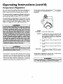
PILOT
LIGHTING - Set here before lighting pilot.
• HOT-
Is a thermostat setting of approximately
120°F, which will supply hot water at the
most economical temap,eratures.The temperature adjustment knob can be turned lower
than _HOT" if desired.
A - Is a thermostat
130°E
setting of approximately
B -Is
setting
a thermostat
140°E
C - ls a thermostat
150°E
AWARNING
Never allow small childrento usea hot water tap, or to draw
their own bathwater. Never leavea childor handicappedpersonunattendedin a bathtub or shower.
of approximate|y
setting of approximately
VERY HOT - Is a thermostat setting of 160°E It is recommended that the dial be set lower whenever
possible.
NOTE: Water temperature range of 120°--140°F
mended by most dishwasher manufacturers.
The thermostat of this water heater has been factory set at its
lowest position, to reduce the risk of scald injury. It is adiustable
and must be reset to the desired temperature setting. The mark
(•) HOT indicative of approximately
120°F is the preferred
starting point. Some states have a requirement
for a lower setting. If you need hotter water, follow directions for temperature
adjustment, but beware of the warnings in this section.
recom-
AWARNING
1
Should overheatingoccur or the gassupplyfail to shut off,
I turn "OFF" the manualgascontrolvalveto the appliance.
I
19
Service and Adjustment
Tank (Sediment)
Burner Inspection
Cleaning
Sediment build-up on the tank bottom may create varying
amounts of noise, and if left in the tank will cause premature
tank failure. In some water areas, you may not be able to drain
all sediment deposits by simply draining the tank. In these cases
Mag Erad (part no. 23600) can be used to help remove the sediment deposits. This may be ordered from theSears Service
Center. For ordering, refer to the _Parts Order List section.
AWARNING
I
Do not .usethis applianceif anypart of it .hL.s
beenunderwatt.
Immediately.call a SearsService Technictanto inspectthe
applianceand to replacethe gascontrol or any part of the
burnersystemwhichhasbeenunderwater.
At least once ayear a visual inspection should be made of the
main burner andpilot burner. The drawing is for your reference.
Venting System Inspection
You should check for sooting which is not normal and will
impair proper combustion.
At least once a year a visual inspection ihould be made of the
venting system. You should look for:
.
• Obstructions which could cause improper venting. The combustion and ventilation air flow must not be obstructed.
Damage or deterioration which could cause improper venting orleakage of combustion products.
Rusted flakes around top of water heater.
_E,WARNING
Chemical vapor corrosionof the flue and vent systemmay
occurif air for combustioncontainscertain chemicalvapors.
Spraycan propellants,cleaningsolvents,refrigerator and air
conditionerrefrigerants, swimming pool chemicals,calcium
and sodiumchloride,waxes,bleach,and processchemicalsam
typicalcompoundswhicham potentiallycorrosive.
_,WARNING
Soot build-upindicatesa problem that requirescorrection
beforefurther use.Turn '_FF" gasto water heater and leave
"OFF" until repairsam made, becausefailureto correctthe
causeof the sootingon result in a fire or explosioncausing
DEATH, SERIOUS BODILY INJURY, OR PROPERTY
DAMAGE.
AWARNING
Obstructed or deterioratedventsystemsmaypresenta serious
healthrisk or asphyxiation.
Burner
I
In the event your burner needs cleaning, use the following
instructions:
AWARNING
]
Be sure the vent pip_onnected
to prevent|
escape of dangerousflue gasseswhich could causedeadlyI
asphyxiation.
Cleaning
If inspection of the burner shows that cleaning is required, turn
the gas control knob clockwise (ff"_)
to the "OFF" position,
depressing slightly.
J
NOTE: The knob cannot be turned from PILOT' to OFF
unless knob is depressed sfighfly. DO NOT FORCE.
AWARNING
]
If after inspectionof _you
found sooting or|
deterioration,something iswrong. Call the localgasutilityto |
correctthe problemand dean or replace the flue and venting|
beforeresuming operationofthe water heater.
I
Loose deposits on or around the burner can be removed by carefully using the hose of a vacuum cleaner inserted through the
access door of the water heater. If the burner needs to be removed
for additional cleaning, call the Sears Service Center to remove
and clean the burner and correct the problem that required the
burner to be cleaned.
20
Service and Adjustment
(cont'd)
Draining
The water heater should be drained if being shut down during
freezing temperatures. Also periodic draining and cleaning of
sediment from the tank may be necessary.
_,WARNING
When checking the temperature-pressure relief valve opera_
tion, make sure that (I) no one is in front of or around the
outlet of the t_mperatu_-pressum relief valve discharge line,
and (2) that the water manually discharged will not cause any
property damage becanse the water may be extremely hot.
If after manually operating the valve, it fails to completely
reset and continues to release water, immediately close the
cold water inlet to the water heater, follow the draining
instructions, and replace the temperature-pressure
relief
valve with a new one.
Turn the gas control knob to the "OFF" position.
CLOSE the cold water inlet valve to the water heater.
• OPEN a nearby hot water faucet and leave open to allow for
draining.
• Connect a hose to the drain valve and terminate to an
adequate drain.
• OPEN the water heater drain valve to allow for tank
draining.
NOTF_ If the water heater is going to be shut down and
drained for an extended period, the drain valve should be
left open with hose connected allowing water to terminate
to an adequate drain.
• Close thedrain valve.
• Follow instructions in the "Filling The Water Heater"
section.
• Follow the lighting instructions in the "Lighting" section to
restart the water heater.
Temperature-Pressure
Valve Operation
Drain Valve Washer
Replacement
NOTE: For replacement,
use a _%2" x :_'." x ¼" thick washer
available at your nearest hardware store. For ordering replacement washers, refer to the "Parts Order List" section.
Relief
The temperature-pressure relief valve must be manually operated
at least once a year.
•
section.
Check for leaks.
Follow the lighting instructions
restart the water heater.
TEMPERATURE-PRESSURE
REL;
Follow_OFF"
"Draining"
instructions.
Turn
gas supply
to water heater.
Turning counter clockwise, remove the hex cap below the
screw handle.
Remove the washer and put the new one in place.
Screw the handle and cap assembly back into the drain valve
and retighten using a wrench. DO NOT OVER TIGHTEN.
Follow instructions
in the "Filling The Water Heater"
in the "Lighting"
section to
VALVE
"_AND CAP
ASSEMBLY
WASHER
DISCHARGE
PIPE
Housekeeping
Failure to install and maintain a new properly listed temperature-pressure relief valve will release the manufacturer from any
claim which might result from excessive temperature or pressure.
Vacuum around base of water heater for dust, dirt, and lint on a
regular basis.
Combustible
materials such as clothing, cleaning materials, or
flammable liquids, etc. must not be placed against or adjacent to
the water heater.
To insure sufficient ventilation and combustion air supply, proper clearances from the water heater must be maintained at all
times.
AWARNING
If the temperature-pressure relief valve on the appliance
weepsor dischargesperiodically, this may be due to thermal
expansion. Your water heater may have a check valve
installedin the water line or a water meter with a check
valve. Consultthe SearsServiceCenter for further information. Do not plugthe temperature-pressurerelief valve.
Service
Before calling for repair service, read the Start Up Conditions
and Operational
Conditions
found in the Troubleshooting
Guide of this manual.
If a condition persists or you are uncertain about the operation
of the water heater, let a qualified person check it out.
Contact SEARS
(1-800-469-4663).
21
Repair
Services
at 1-800-4-MY-HOME
Troubleshooting
Guide
Start Up Conditions
CONDENSATION
SMOKE/ODOR
Whenever the water heater is filled with cold water, a certain
amount of condensation will form while the burner is on. A
water heater may appear to be leakin_when in fact the water is
condensation. This usually happens wnen:
• When a new water heater is filled with cold water for the
first time.
• When gas burns and water vapor is produced in water
heaters, particularly high efficiency models where flue temperatures arelower.
When you use large amounts of hot water, in a short time
and the refill water Is very cold.
It is not uncommon to experience a small amount of smoke and
odor during the initi_ start-up. This is due to burning offof oil
from metal parts, and will disappear in a short while.
THERMAL
EXPANSION
Water supply systems may, because of high line pressure, frequent cut-offs, the effects of water hammer and others, have
installed devices such as pressure reducing valves, check valves,
back flow preventers, etc. to control these types of problems.
When these devices are not equipped with an internal by-pass,
and no other measures are taken, the devices cause the water system to be closed. As water is heated, it expands (thermal expansion) and closed systems do not allow for the expansion of heated water.
Moisture from the products of combustion
condense on the
cooler tank surfaces and form drops of water ".which may fall
onto the burner or other hot surfaces to produde a "sizzling" or
"frying" noise.
The water within the water heater tank expands as it is heated
and increases the pressure of the water system. If the relieving
point of the water heater's remperature-pressure relief valve is
reached, the valve will relieve the excess pressure. The temperature-pressure relief valve is not intended for the constant
relief of thermal expansion. This is an unacceptable condition
and must be corrected.
Excessive condensation
can cause pilot outage due to water running down the flue tube onto the main burner and putting out
the pilot.
Because of the suddenness and amount of water, condensation
water may be diagnosed as a "tank leak". After the water in the
tank warms up (about 1-2 hours), the condition should
disappear.
It is recommended that any devices installed which could create
a closed system have a by-pass and/or the system have an expansion tank to relieve the pressure built by thermal expansion in
the water system. Expansion tanks are available for ordering
through the Sears Service Center. Contact the local plumbing
inspector, water supplier, and/or the Sears Service Center for
assistance in controlling these situations.
Do not assume the water heater is leaking until there has been
enough time for the water in the tank to warm up.
An undersized water heater will cause more condensation.
The
water heater must be sized properly
to meet the family's
demands for hot water including dishwashers, washing machines
and shower heads.
Thermal
Excessive condensation
may be noticed during the winter and
early spring months when incoming water temperatures
are at
their lowest.
Good venting is essential for a gas fired water heater to operate
properly as well as to carry away products of combustion
and
water vapor.
Expansion
Tank Specifications
Model
Number
Tank Capacity
In Gallons
Dimensions in Inches I Pipe Fitting
Diameter
Length : On Tank
153.331020
2
5
153.331050
AWARNING
8 inches
llinches
12_ inches]
14_inehes
i
_" Male
_"Male
Expansion Tank Sizing Chart
HOTTER WATER CAN SCALD:Water heatersareintendedto
producehot water. Water heated to a temperaturewhichwill
satisfyclotheswashing,dishwashing,and other sanitizingneeds
canscaldand permanently injureyou uponcontact.Somepeople are more likelyto bepermanentJyinjured by hot waterthan
others,These includethe elderly,children,the infirm,or physicab
lylmentally handicapped.
If anyoneusinghot waterin yourhome
fitsintooneofthesegroupsor ifthere isa localcodeor statelaw
requiringa certaintemperaturewater at the hot water ta_ then
you musttakespecialprecautions.
In additionto usingthe lowest
mssibletemperature settingthat satisfies
yourhot water needs,
a meanssuchasa mixingvalve,shouldbeusedat the hot water
tapsusedbythese people or at the water heater.Mixingvalves
areavailableat plumbingsupplyor hardwarestores.Followmanufacturers instructionsfor installationof the valves.Before
changing the factory setting on the thermostat, read the
'*l"emperotureRegulation"sectionin this manual.
Expansion
Tank
Capacity
Needed
Inlet*
Water
Pressure
30
40psi
50psi
60psi
70psi
80psi
2
2
2
2
2
Water Heater Capacity (Gallons)
I
40
50
2
2
2
2
5
2
2
5
5
5
*Highest recorded inlet water pressure
regulated water pressure.
i
66
5
5
5
5
5
in a 24 hour period
82
5
5
5
5
5
or
NOTE:
Expansion
tanks are pre-charged
with a 40 psi air
charge. If the inlet water pressure is higher than 40 psi, the
expansion tanks air pressure must be adjusted to match that
pressure, but must not be higher than 80 psi.
22
Troubleshooting
Guide (cont'd)
Operational
HOT
COLD
WATE_HEAT_
SMELLY
O)
COLD WATER
INLET FITTING
pRESSURE
REDUCING
VALVE
Conditions
WATER
In each glasslined water heater there is installed at least one
anode rod (see parts section) for corrosion protection of the
tank. Certain water conditions will cause a reaction between this
BY-PASS
(t)
rod and the water. The most common complaint assodated with
the anode rod is one of a rotten egg smell. This odor is derived
from hydrogen sulfide gas dissolved in the water. The smell is
the result offuur factors which must all be present for the odor
to develop:
EXPANSION
TANK
_)
PRESSUREGAUGE
a. a concentration of sulfate in the supply warer.
b. little or no dissolved oxygen in the water.
c. a sulfate reducing bacteria within the water heater. - (This
harmless bacteria is non-.toxic to humans.)
d. an excess of active hydrogen in the tank. This is caused by
the corrosion protective action of the anode.
INLET C
WATER
SHUTOFF
RECOMMENDED INSTALLATION
(VERTICAL MOUNTING)
FLOOR,CEIUNG
JOLT,ETC.
WATER HEATER
COLD WATER
INLET FITTING
HOT
Smelly water may be eliminated or reduced in some water heater
models by replacing the anode(s) with one of less active material,
and then chlorinating the water heater tank and all hot water
lines. Contact Sears Service for further information concerning
an Anode Replacement Kit #9001453 and this Chlorination
Treatment.
COLD
lfthe smelly water persists after the anode replacement and chlorination treatment, we can only suggest that continuous chlorination and filtering conditioning equipment be considered to
eliminate the water pmblem.
STRAPPING
o)
PRESSURE
REDUCING
VALVE WITH
BY-PASS
O)
Do not remove the anode leaving the tank unprotected.
doing so, all warranty on the water heater tank is voided.
INLET COLD
WATER
SHUTOFF
EXIPANSION
"AIR"
IN HOT WATER
By
FAUCETS
AWARNING
(2)
HYDROGEN GAS: Hydrogen gas can be produced in a hot
water system that has not been used for a long period of time
(generally two weeks or more). Hydrogen gas is extremely
flammable and explosive. To prevent the possibility of injury
under these conditions, we recommend the hot water faucet
be opened for several minutes at the kitchen sink before any
electrical applianceswhich are connected to the hot water system are used (such as a dishwasher or washing machine). If
PRESSUREGAUGE
ALTERNATE RECOMMENDED
INSTALLATION
(HORIZONTAL MOUNTING)
STRANGE
hydrogengas is present, there will probably be an unusual
soundsimilarto air escapingthrough the pipeasthe hot water
faucet is opened. There must be no smoking or open flame
SOUNDS
Possible noises due to expansion and contraction of some metal
parts during periods of heat-up and cool-down do not represent
harmful or dangerous conditions.
near the lancet at the time it is open.
Condensation
causes sizzling and popping with the burner area
during heating and coolin_ periods and should be considered
normal. See "Condensation
section.
23
Troubleshooting
Operational
HIGH
Conditions
TEMPERATURE
SHUT
Guide (cont'd)
(cont'd)
OFF SYSTEM
WATER
This water heater is equipped with an automatic gas shut offsystem. The high temperature shut off is built into the gas control
valve. This system shuts off the gas supply to the water heater
burners when high water temperatures are present. It is nonresetrable. If the high temperature shut off activates, the gas control valve must be replaced. If this were to occur, turn OFF the
entire gas supply to the water heater. Contact the Sears Service
Center.
I
NOTE: A period of time is necessary after an adjustment
has been made for the water temperature to reach the new
temperature setting.
• If lower temperature settings will not lower the water temperature, call the Sears Service Center.
_,WARNING
Due to the nature of the typical gas water heater, the
water temperature in certain situations may be hotter
than the thermostat setting.
Short, frequent draws of hot water - especiallywith very
coldincoming water - can shockthe thermostat into brief
operation resulting in hotter and hotter layers of water
closerto the top of the tank.
Changes in hot water usage patterns or raising the temperature differential between the cut-on of the thermostat and the cold water temperature will usuallyeliminate
the problem.
turn "OFF" the manual gascontrol valveto the appli_, ce.
ENOUGH
OR NO HOT WATER
•
Check the manual gas shut offvalve to be sure it is open.
•
Check the pilot flame. It may have gone out. All models have
an opening behind the outer door for viewing the pilot.
•
If the pilot is not lit, follow the "Lighting" instructions in this
manual or located above the gas control valve on the water
heater to relight the pilot. If the water was extremely hot and is
now cold, the high limit safety temperature shut off may have
put out the burner and pilot. If the high temperature shut off
activates, the gas controlvalve
must be replaced. Contact the
Sears Service Center.
•
The gas control knob must be turned to the _ON" position.
•
The temperature adjustment dial may be set too low. See the
'Temperature Regulat'on" section.
HOT
• The temperature adjustment.dial may be set too high. See the
"TemperatureAdjustment section.
.
_,WARNING
Should overheatingoccur or the gassupplyfail to shut off,
NOT
IS TOO
• The gas company can check the gas input to see if it is correct.
An underflred water heater will not heat water as quickly.
• Look for leaking or open hot water faucets. Make sure all are
closed.
• The cold water inlet temperature
may be colder during the
winter months. It will take longer to heat the water and seem
like less hot water.
• If you cannot find what is wrong, call the Sears Service Center.
24
Troubleshooting
Guide (cont'd)
Leakage Checkpoints
Use this guide to check a "Leaking"water heater. Many suspect- ed "Leakers" are not leaking tanks. Often the source of the water
can be found and corrected.
•
_,CAUTION
Read this manual fi_
checking the water
heater make sure the gas supply has been turned
J"OFF", and never turn the gas "ON" before the tank is J
I completely full of water.
I
If you are not thoroughly
familiar with your local gas codes,
your water heater, and safety ptacdces, contact the
Center to check the water heater.
ACAUTION
N..ev.eruse this water heater unlessit is completely filled
with water. To prevent damage to the tank, the tank i
must be filled with water; Water must flow from the hot
water faucet before turning "ON" gas to the water
I heater"
i
"
I
O
Water at the draft hood is water vapor which has
condensed out of the combustion products. This is caused
by a problem in the vent. Contact the Sears Service Center.
O
*Condensation may be seen on pipes in humid weather or
pipe connections may be leaking.
O'The
O
primary anode rod fitting may be leaking.
Small
amounts
the temperature-pressure
relief valve
may ofbewater
due from
to thermal
expansion
or high
water pressure in your area,
o'The the tank
temperature-pressure
fitting.
O
O'The
O
O
relief valve may be leaking at
Water from a drain valve may be due to the valve opened
slightly.
drain valve may be leaking at the tank fitting.
Combustion
can
condense on product_
the cooler contain
surfaces water
of thevapor
tank.which
Droplets
form and drip into the fire or run on the floor. This is
common at the time ofstartup after installation and when
incoming water is cold.
Water in the water heater bottom or on the floor may be
from condensation,
loose connections, or the relief valve.
DO NOT replace the water beater until a full inspection
of all possible water sources is made and necessary
corrective steps taken. Leakage from other appliances,
water lines, or ground seepage should also be checked.
NOTE: To check where threaded portion enters tank,
insert cotton swab between jacket opening and fitting.
If cotton is wet, follow "Draining" instructions in the
"Service and Adjustment" section and then remove
fitting. Put pipe dope or teflon tape on the threads
and replace. Then follow "Filling the Water Heater"
instructions in the Installation Instructions section.
25
Parts Order
List
POWER MISER TM 10 GAS WATER HEATERS
MODEL
153.330401
153.330451
153.330501
153.330551
153.330701
153.330751
NUMBERS:
40
40
50
50
75
75
Gal. High Altitude
Gal.
Gal. High Altitude
Gal.
Gal. High Altitude
Gal
2O
18
19
14
26
Parts Order
POWER MISER
TM
List (cont'd)
10 GAS _rATER HEATERS
MODEL NUMBERS:
153.330401
153.330451
153.330501
153.330551
153.330701
153.330751
KEY
NO.
1
2
3
4
5
6
7
40
40
50
50
75
75
Gal. High Altitude
Gal.
Gal. High Altitude
Gal.
Gal. High Altitude
Gal
153.330401
153.330451
PART DESCRIPTION
Temperature-Pressure
Primary Anode Rod
Cold Inlet Nipple
Drain Valve
Relief Valve
(Heat Trap)
Drain Valve Washer
('%2" x 'Y." x ¼" thick)**
Model Ratin_ Plate
Pilot
9000071
9000734
9000071
9000734
9000948
9000254
9001584
0270118
9000284
Model Numbers
153.330501
153-330551
PART NUMBERS
9000071
9000071
153-330701
153-330751
9000734
9000734
9000071
9000734
9000071
" 9000734
9000948
9000254
9000948
9000254
_000948
9000254
9000948
9000254
9000948
9000254
9001584
0270118
9000284
9001584
0270118
9001584
0270118
9000284
9000284
9001584
0270118
9000284
9001584
0270118
9000284"
4233900
42 33900
42 33900
9000278
0230144
#29
9002621
8
Thermocouple*
42 33900
42 33900
4233900
9
10
9000278
0230141
#36 (HA)
9002615
9000278
0230120
#33
9002615
9000278
9000278
0230141
#36 (HA)
0230120
#33
11
Pilot Tubing w/Fitrings
Burner Orifice
(Drill Size)
Manifold
9002617
9002617
9000278
0230160
#31 (HA)
9002621
12
Burner
9002411
9002411
9002411
9002411
9002411
9002411
13
Manifold
9002494
9002494
9002494
9002494
9002494
9002494
14
Inner Door
9000281
9000281
9000281
9000281
9000281
9000281
15
Gas Control
Valve
F145-1277
F145-1277
F145-1277
F145-1277
F145-1277
F145-1277
16
Temperature
Adjustment
F145-1280
F145-1280
F145-1280
F145-1280
F145-1280
F145-1280
17
18
Restrictor Ring
Dip Tube
9001208
9002444
9001208
9002444
9001208
9001208
9002443
9002443
9000297
9002444
9000297
9002444
Cover
Knob
19
Flue Baffle
9000944
9000944
9000945
9000945
9001452
9001452
20
Draft Hood
9000273
9000273
9000273
9000273
9000274
9000274
21
9001792
9001792
9001792
9001792
9001792
9001792
#
Secondary Anode Rod and
Hot Outlet Nipple (Heat Trap)
Manual
#
Mag-Erad
0002915250
23600
* These parts are also available at most Sears retail stores.
*" Also available at most hardware stores.
tReplaced only on return of damaged plate.
Now that you have purchased your Gas Water Heater, should a need ever exist for repair parts or service, simply contact any SEARS Service
Center or call 1-800-4-MY-HOME
(1-800-469-4663).
Be sure to provide pertinent facts when you call or visit.
All parts listed may be ordered from any SEARS Service Center, most SEARS stores and by calling 1-800-366-PART (1-800-366-7247).
If the
parts you need are not stocked locally, your order will be electronically transmitted to a SEARS Repair Parts Distribution Center for handling.
The model number
of your Gas Water Heater will be found on the model rating plate located near the gas control valve.
WHEN ORDERING
REPAIR PARTS, ALWAYS GIVE THE
FOLLOWING
INFORMATION:
MODEL NUMBER
PART DESCRIPTION
PART NUMBER
NAME OF ITEM.
THIS IS A REPMR PARTS LIST, NOT A PACKING LIST
27
Warranty
a. Adjustingthermostat.
b. Lighting pilot.
c. Leaksin pipes or fittings.
d. Improper venting
e. Condensation
About Your Warranty
THE PRICE OF YOUR WATER HEATER DOES NOT INCLUDE
A FREE CHECKUP SERVICECALL. On Water Heater Installations
Arranged BySears,Searswarrants the installation.
ON INSTALLATIONS NOT MADE BY SEARS AUTHORIZED
CONTRACTORS:
1. YourSearswarranty appliesto the product only.
2. Searsdoesnot warrant the installation.
3. A charge will be made on service calls due to poor or incomplete
installation.These indude:
This manual is in non:technical language. It may help you avoid the
cost of a needlessservicecall. Manyservice callsreallyarent needed.
Such aswhen:
1. The gas is turned "OFF".
2. The pilot is out.
3. A gas orwater leak is due to loosepipe orconnections.
LIMITED WARRANTY ON TANKS THAT LEAK
Through ten (10) years from the date of purchase, ifa leak occursin the tank, Sears will furnish, free of charge, a new current model water
heater of closest available capacity and quality. If purchaser does not qualify for free installation as provided in the One Year Limited Labor
Warranty below, there x¢lllbe a charge for installation.
If the replacement water heater ofdosest availablecapacity and quality does not meet current applicable government standards, there will be
a charge for the difference in price between the replacement which does not meet government standards and one which does meet government standards
If the water heater is subjected to commercial, institutional, or industrialuse or use in residences of two families or more, the abovewarranty
coverage for tanks that leak is effective for two years from the date of purchase and the Limited Warranty On Parts below is effective for one
year from the date of purchase.
LIMITED WARRANTY ON PARTS
Through ten (10) years from the date of purchase,when your SearsKenmorewater heater is installedand operated in accordancewith the
instructions in this manual, if a part fails due to a failurein materialsorworkmanship,Searswill furnish a replacementpart free of charge.
If purchaserdoes not qualifyfor free installation asprovided in the One YearLimitedLaborWarranty below,there will be a chargefor
installation.
ONE YEAR LIMITED LABOR WARRANTY ON WATER HEATER
When your SearsKenmorewater heareris installedby Searsor itslicensedsubcontractorand is operated in accordancewith the instructions
in this manual, Searswill, for oneyearfrom the date of purchase:
Install, freeof charge,the replacementwater heater as providedby the aboveLimitedTankLeakWarranty.
Repair,freeof charge,defectsin materialsorwod_nanship of the water heater asprovided by the aboveLimitedWarrantyon Parts.
To obtain warranty service, SIMPLY CALL 1-800-4-MY-HOME (1-800-469-4663).
in the United States.
This warranty applies only while this product is in use
This warranty gives you specific legal rights and you may also have other rights which vary from state to state.
SEARS, ROEBUCK AND CO., Dept. 817 WA, Hoffman Estates, 1L 60179
Sears Installation
Warranty
Sears Installation Policy
In addition to any warranty extended to you on the Sears merchandise
involved, which warranty becomes effective the date the merchandise is
installed should the workmanship of any Sears arranged installation
prove faulty within one year, Sears will, upon notice from you, cause
such faults to be corrected at no additional cost to you. If you want this
heater professionally installed by Sears contact your Sears Salesperson.
They will arrange for prompt, quality installation.
delivereddirectlytoyourhome
Call6 am- 11 prn(CST),7 daysaweek
Forthe1-800-366-PART
repairor replacement
paitsyouneed
All installation labor arranged by Sears shall be performed in a neat,
workmanlike manner in accordance with generally accepted trade practices. Further, all installations shall comply with all local laws, codes
regulations and ordinances. The customer shall also be protected, during installation, by insurance relating to property damage, Worker's
Compensation and Public Liability.
If you want this water heater professionally installed by Sears contact
your Salesperson. They will arrange for prompt, quality installation by
Sears authorized contractors.
Call24 hoursa day,7 daysaweek
'1-800-4-MY-HOME
I
_.ARS
i
Forin-home
majorbrandrepairservice
(r-soo-4os-4ssa)
(1-800-366-7278)
"ihe
Service
Slde
ofSea_
The model number of your water heater is found on the model rating plate on the front of the waterheater.
I 1-98
Sears, Roebuck
and Co., Hoffman
Estates,
IL 60179
U.S.A.
0002915250-0