1
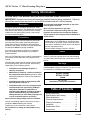
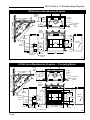
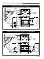
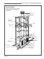
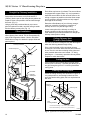
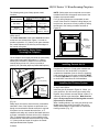
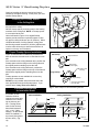
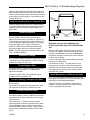
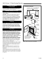
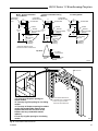
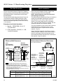
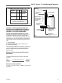
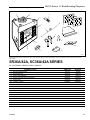
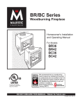
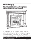
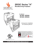
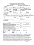
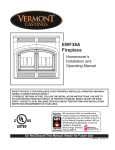
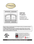
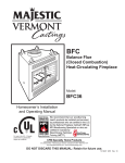
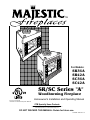
™
12345678901234567890123456789012123456
12345678901234567890123456789012123456
12345678901234567890123456789012123456
12345678901234567890123456789012123456
12345678901234567890123456789012123456
12345678901234567890123456789012123456
12345678901234567890123456789012123456
12345678901234567890123456789012123456
12345678901234567890123456789012123456
12345678901234567890123456789012123456
12345678901234567890123456789012123456
12345678901234567890123456789012123456
12345678901234567890123456789012123456
12345678901234567890123456789012123456
12345678901234567890123456789012123456
12345678901234567890123456789012123456
12345678901234567890123456789012123456
12345678901234567890123456789012123456
12345678901234567890123456789012123456
12345678901234567890123456789012123456
12345678901234567890123456789012123456
12345678901234567890123456789012123456
12345678901234567890123456789012123456
12345678901234567890123456789012123456
12345678901234567890123456789012123456
12345678901234567890123456789012123456
12345678901234567890123456789012123456
12345678901234567890123456789012123456
12345678901234567890123456789012123456
12345678901234567890123456789012123456
12345678901234567890123456789012123456
12345678901234567890123456789012123456
12345678901234567890123456789012123456
12345678901234567890123456789012123456
12345678901234567890123456789012123456
12345678901234567890123456789012123456
12345678901234567890123456789012123456
12345678901234567890123456789012123456
12345678901234567890123456789012123456
12345678901234567890123456789012123456
12345678901234567890123456789012123456
12345678901234567890123456789012123456
12345678901234567890123456789012123456
12345678901234567890123456789012123456
12345678901234567890123456789012123456
12345678901234567890123456789012123456
12345678901234567890123456789012123456
12345678901234567890123456789012123456
12345678901234567890123456789012123456
12345678901234567890123456789012123456
12345678901234567890123456789012123456
12345678901234567890123456789012123456
12345678901234567890123456789012123456
12345678901234567890123456789012123456
12345678901234567890123456789012123456
12345678901234567890123456789012123456
12345678901234567890123456789012123456
12345678901234567890123456789012123456
12345678901234567890123456789012123456
12345678901234567890123456789012123456
12345678901234567890123456789012123456
12345678901234567890123456789012123456
12345678901234567890123456789012123456
12345678901234567890123456789012123456
12345678901234567890123456789012123456
12345678901234567890123456789012123456
12345678901234567890123456789012123456
12345678901234567890123456789012123456
12345678901234567890123456789012123456
12345678901234567890123456789012123456
12345678901234567890123456789012123456
12345678901234567890123456789012123456
12345678901234567890123456789012123456
12345678901234567890123456789012123456
For Models:
SR36A
SR42A
SC36A
SC42A
SR/SC Series "A"
Woodburning Fireplace
For use in U.S./Canada
Underwriter's Laboratories Report No. MH6018
Homeowner's Installation and Operating Manual
CFM Specialty Home Products
410 Admiral Blvd. • Mississauga, Ontario, Canada L5T 2N6 • 905-670-7777
www.majesticproducts.com • www.vermontcastings.com
DO NOT DISCARD THIS MANUAL: Retain for future use.
7412948 2/04 Rev. 14
SR/SC Series "A" Woodburning Fireplace
Safety Information
PLEASE READ THIS MANUAL BEFORE INSTALLING AND USING FIREPLACE.
IMPORTANT: Read all instructions and warnings carefully before starting installation. Failure to
follow these instructions may result in a possible fire hazard and will void the warranty.
Description
The SR/SC Series "A" fireplaces are solid fuel, woodburning premium fireplaces. The SR36A/42A are radiant
clean-face models and the SC36A/42A are circulating
models with removable grilles (louvres). Both models
are fully insulated fireplaces.
Precautions
CFM Specialty Home Products fireplaces and component parts have been highly tested and will operate
safely when installed in accordance with instructions
provided in this manual. Carefully read and understand
all instructions before beginning installation.
If you notice any damage to fireplace or component
parts, immediately report damage to your Majestic
Fireplaces dealer.
Only use CFM Specialty Home Products components or
the warranty will be voided and a fire hazard may be
created.
CFM Specialty Home Products warranty will be voided
by and CFM Specialty Home Products disclaims any
responsibility for the following actions:
• Installation of any damaged fireplace or
chimney component;
• Modification of fireplace, chimney assembly or
any component parts thereof; (except for chase
flashings as detailed in Chimney Top installation
instructions).
• Installation other than as instructed by CFM
Specialty Home Products; or
Do not install combustible materials on any of the
black fireplace surround.
Burn only solid wood fuel or gas logs.
Do not install a solid fuel burning insert or other
products not specified for use with this fireplace.
These fireplaces are not approved for installation in
mobile homes.
Proposition 65 Warning: Fuels used in gas,
woodburning or oil fired appliances, and the products
of combustion of such fuels, contain chemicals known
to the State of California to cause cancer, birth defects
and other reproductive harm.
California Health & Safety Code Sec. 25249.6
Drafts
The fireplace should not be located in areas that create
drafts (ie: frequently opened doors and central heating
air inlets/outlets) that hamper the normal flow of air into
the fire.
Gas Logs
If you plan to install a gas log, the gas line should be
installed before framing the fireplace. The gas line must
be installed by a certified gas line installer.
SR36A / SR42A
SC36A / SC42A
Listed
UL / ULc127
Standard for Factory Built Fireplaces
• Installation and/or use of any component part
not manufactured or approved by CFM Specialty Home Products in combination or
assembly with a Majestic Fireplaces fireplace
system, notwithstanding any independent
testing laboratory or other third party approval
of such component parts or accessory.
Any such action may possibly cause a fire hazard.
Consult local building codes to ensure that you are in
compliance before installing the fireplace.
Fireplaces must be vented to the out-of-doors.
Do not obstruct or modify air inlets/outlets in any
manner.
2
Table of Contents
Safety Information . . . . . . . . . . . . . . . . . . 2
Specifications and Framing . . . . . . . . . . . 3
Parts Identification . . . . . . . . . . . . . . . . . . 5
Chimney Requirements . . . . . . . . . . . . . . 6
Planning Information . . . . . . . . . . . . . . . . 7
Installation . . . . . . . . . . . . . . . . . . . . . . . . 8
Replacement Parts . . . . . . . . . . . . . . . . 19
Accessories . . . . . . . . . . . . . . . . . . . . . . 20
7412948
SR/SC Series "A" Woodburning Fireplace
SR36A Series Woodburning Fireplace
22" (559mm)
Rough
Opening
Depth
48¹⁄₂" (1232mm)
¹⁄₂" (13mm)
22¹⁄₂"
(572mm)
11" Dia.
(279mm)
8¹⁄₄"
(210mm)
8" Dia.
(203mm)
⁵⁄₈" Recessed
(16mm) Nailing
Flange
68
¹⁄₂
" ( ⁵⁄₈"
17 (1
40 6m
m m
m )
)
87
6m
"(
34
¹⁄₂
48¹⁄₂" (1232mm)
m
)
22"
(559mm)
¹⁄₂"
Rough Opening Width 41"
(1041mm)
Rough
Opening
Height
39⁵⁄₈"
(1006mm)
Outside
Air
7¹⁄₂"
(191mm)
Gas Line
Access
36"
(914mm)
14⁵⁄₈"
(372mm)
11"
(279mm)
8"
(203mm)
7¹⁄₂"
(191mm)
43³⁄₄"
(1111mm)
3"
(76mm)
15 ³⁄₈"
(391mm)
24"
(610mm)
22³⁄₄"
(578mm)
Gas Line
Access
7³⁄₄"
(197mm)
40"
(1016mm)
Electrical
Access
FP589
Fig. 1 SR36A Series specifications and framing.
SC36A Series Woodburning Fireplace — Circulating Model
8¹⁄₄"
22¹⁄₂"
(572mm) (210mm)
22"
(559mm)
Rough
Opening
Height
Rough Opening Width 41"
(1041mm)
11" Dia.
(279mm)
8" Dia.
(203mm)
⁵⁄₈" Recessed
(16mm) Nailing
Flange
68
¹⁄₂"
¹⁄₂
" ( ⁵⁄₈
17 " (
40 16
m mm
m )
)
m
87
6m
"(
¹⁄₂
34
48¹⁄₂" (1232mm)
)
48¹⁄₂" (1232mm)
¹⁄₂" (13mm)
22" (559mm)
Rough
Opening
Depth
39⁵⁄₈"
(1006mm)
7¹⁄₂"
(191mm)
Outside Air
Gas Line
Access
36"
(914mm)
14⁵⁄₈"
(372mm)
11"
(279mm)
8"
(203mm)
7¹⁄₂"
(191mm)
43³⁄₄"
(1111mm)
15³⁄₈"
(391mm)
3"
(76mm)
38¹⁄₄"
(971mm)
24"
22³⁄₄"
(578mm) (610mm)
Gas Line
Access
7³⁄₄"
(197mm)
35¹⁄₂" (902mm)
40" (1016mm)
1³⁄₄"
(45mm)
Electrical Access
FP590
Fig. 2 SC36A Series specifications and framing.
7412948
3
SR/SC Series "A" Woodburning Fireplace
SR42A Series Woodburning Fireplace
26¹⁄₄"
(667mm)
Rough
Opening
Depth
50" (1270mm)
¹⁄₂" (13mm)
11" Dia.
(279mm)
8¹⁄₄"
22¹⁄₂"
(210mm)
(572mm)
22"
(559mm)
8" Dia.
(203mm)
m
)
4m
9 1 ⁵⁄ ₈
m " (1
m 6
) m
91
"(
Rough
Opening
Height
17
36
¹⁄ ₂
"(
¹⁄₂"
Rough Opening Width 47"
(1194mm)
70
50" (1270mm)
m
)
⁵⁄₈" Recessed
(16mm) Nailing
Flange
7¹⁄₂"
(191mm)
43³⁄₄"
(1111mm)
39⁵⁄₈"
(1006mm)
Outside
Air
7¹⁄₂"
(191mm)
Gas Line
Access
14⁵⁄₈"
(372mm)
11"
(279mm)
8"
(203mm)
42"
(1067mm)
3"
(76mm)
15⁵⁄₈"
(397mm)
22³⁄₄"
(578mm)
24"
(610mm)
Gas Line
Access
7³⁄₄"
(197mm)
46"
(1168mm)
Electrical
Access
FP591
Fig. 3 SR42A Series specifications and framing.
SC42A Series Woodburning Fireplace — Circulating Model
8¹⁄₄"
22¹⁄₂"
(210mm)
(572mm)
22"
(559mm)
¹⁄₂"
70
¹⁄₂
" ( ⁵⁄₈
17 " (
91 16
m mm
m )
)
36
"(
91
4m
m
)
50" (1270mm)
50" (270mm)
¹⁄₂" (13mm)
26¹⁄₄"
(667mm)
Rough
Opening
Depth
Rough
Opening
Height
7¹⁄₂"
(191mm)
43³⁄₄"
(1111mm)
39⁵⁄₈"
(1006mm)
7¹⁄₂"
(191mm)
Outside Air
Gas Line
Access
42"
(1067mm)
14⁵⁄₈"
(372mm)
11"
(279mm)
8"
(203mm)
Rough Opening Width 47"
(1194mm)
15³⁄₈"
(391mm)
3"
(76mm)
Electrical Access
11" Dia.
(279mm)
8" Dia.
(203mm)
⁵⁄₈" Recessed
(16mm) Nailing
Flange
38¹⁄₄"
(971mm)
24"
22³⁄₄"
(578mm) (610mm)
Gas Line
Access
7³⁄₄"
(197mm)
38" (965mm)
46" (1168mm)
1³⁄₄"
(45mm)
FP592
Fig. 4 SC42A Series specifications and framing.
4
7412948
SR/SC Series "A" Woodburning Fireplace
Chase Installation
Insulation methods shown are optional
for cold climate, not a requirement for
unit operation.
Termination Cap
Storm Collar
Pan Flashing
Batt Insulation
(cut out around
fiestop)
Draftstop
Firestop
Ceiling Level
Standoff
Surround
Damper Control
Nailing Flange
Gas Line Access
(both sides)
Gas Line Knockout
(both sides)
Screen
Electrical Access
Grate
Firebox
Outside Air Cover Plate
Metal Safety Strips
(1, 2 or 3 pieces)
FP554
Fig. 5 Fireplace and chase parts identification.
7412948
5
SR/SC Series "A" Woodburning Fireplace
Chimney Requirements - Offset Installations
OFFSET
CHIMNEY FLUE EXIT
RISE
CHIMNEY
SECTION
IWF282
B
A
D
E
6 FT.
G
30˚
RETURN
ELBOW
30˚
OFFSET
ELBOW
RISE
C
H
OFFSET
30˚
RETURN
ELBOW
30˚
OFFSET
ELBOW
B
30˚ Elbow Offsets
G
SKCS8
SUPPORT
H
HEARTH
FLOOR
Example 1
Example 2
Example 3
Notes: G + H cannot exceed 20 feet.
Air Space Clearances: SK8 (2-wall) = 1¹⁄₂" and "S" Series (3-wall) = 2"
IWF269
Illustration Key
The following safety rules apply to offset
installations (letters correspond with
illustration above):
C. The chimney cannot be more than 30˚
(45˚ in Canada) from the vertical plane in
any installation*.
A. Height of the chimney is measured
from the hearth to the chimney exit.
D. The maximum length of the angled run
of the total chimney system is 20 feet. (G
plus H cannot exceed 20 feet.)
SR/SC36A
Maximum:
90'0"
Minimum:
Without Elbows 12' 6"
With 2 Elbows* 14' 6"
With 4 Elbows* 21' 0"
E. A chimney support (Model SKCS8) is
required every 6 feet of angled run of
chimney. Chimney supports are required
for every 30 feet and 60 feet (SK8 pipe)
or 20 feet and 40 feet (3-wall pipe) of
vertical chimney height above the hearth.
SR/SC42A
90'0"
12' 6"
14' 6"
21' 0"
B. Do not use more than 4 elbows per
chimney.
Attach the straps of the return (top) elbow
to a structural framing member.
The offset (first) elbow of any pair does
not have straps.
* In Canada, two (2) SK845 are allowed.
Determine the offset distance of your
chimney arrangement from the centerline
of the fireplace to the centerline of the
chimney where it is to pass through the
first ceiling.
NOTE: This offset distance may not be
your full offset distance. See Examples 2
and 3.
1' 1¹⁄₂' 3' 4'
Chimney
Support
ELBOW
0
1
0
2
1
0
2
0
0
1
0
0
1
0
0
0
0
0
0
0
0
0
0
0
0
0
0
0
0
0
0
0
0
0
0
0
0
0
0
0
0
0
0
0
0
0
0
0
0
0
0
0
1
1
1
1
1
1
1
1
1
1
1
1
2
2
2
2
2
2
2
2
2
2
2
2
3
3
3
3
0
0
1
0
1
0
1
0
1
0
1
0
1
0
1
0
1
0
1
0
1
0
1
0
1
0
1
0
1
0
1
0
1
0
1
0
1
0
1
0
0
0
0
0
0
1
0
0
1
0
0
2
0
1
2
0
1
3
0
2
3
1
2
0
1
3
0
2
3
1
2
0
1
3
0
2
3
1
2
0
0
0
0
0
0
0
0
1
0
1
1
0
1
1
0
2
1
0
2
1
0
2
1
3
2
1
3
2
1
3
2
4
3
2
4
3
2
4
3
5
Offset
Rise
3"
8¹⁄₄"
11¹⁄₄"
13¹⁄₂"
16¹⁄₂"
20¹⁄₄"
21³⁄₄"
26¹⁄₄"
28¹⁄₂"
31¹⁄₂"
34¹⁄₂"
37¹⁄₂"
41¹⁄₂"
45"
47¹⁄₄"
51"
53¹⁄₄"
56¹⁄₄"
59¹⁄₄"
62¹⁄₄"
64¹⁄₂"
68¹⁄₄"
70¹⁄₂"
74¹⁄₄"
78"
81"
84"
87"
89¹⁄₄"
93"
95¹⁄₄"
99¹⁄₄"
101¹⁄₄"
104¹⁄₄"
107¹⁄₄"
110¹⁄₄"
114"
117³⁄₄"
120"
123³⁄₄"
11"
20"
25¹⁄₄"
29¹⁄₄"
34¹⁄₄"
40³⁄₄"
43¹⁄₂"
51¹⁄₄"
55¹⁄₄"
60¹⁄₄”
65¹⁄₂"
70³⁄₄"
77³⁄₄"
83³⁄₄"
87¹⁄₂"
94"
98"
103¹⁄₄"
108¹⁄₂"
113¹⁄₂"
117¹⁄₂"
124"
128"
134¹⁄₂"
140³⁄₄"
146"
151¹⁄₄"
156¹⁄₂"
160¹⁄₄"
166³⁄₄"
170³⁄₄"
177³⁄₄"
181³⁄₄"
186¹⁄₄"
191¹⁄₂"
196³⁄₄"
203¹⁄₄"
209³⁄₄"
213¹⁄₂"
220"
Fig. 6 Chimney system requirements.
6
7412948
SR/SC Series "A" Woodburning Fireplace
Planning Information
Preplanning an installation is very important to ensure
safety and to save time and money. An installer must
predetermine where a fireplace will be set and how the
chimney system will be run.
Mounting The Fireplace
1. A flat combustible surface.
2. A raised wooden platform.
3. A concrete block or other solid object placed beneath each of the four (4) corners of the fireplace.
The fireplace must be spaced 1/2" (13mm) from a
combustible back wall and 1/2" (13mm) from a combustible side wall or support. (Page 14, Fig. 20)
Planning the Chimney Run
L1
L1
MODEL SK
2 WALL CHIMNEY
SK81
SK818
SK83
SK84
TOTAL
LENGTH
(LT)
11¹⁄₂"
17¹⁄₂"
35¹⁄₂"
47¹⁄₂"
6. A guy wire stabilizer is required for chimneys
extending more than 6' (1.8m) above a roof line.
The Ten Foot Rule
A fireplace may only be mounted on the following
surfaces:
LT
5. No more than 2 offsets (4 total 30° elbows in U.S./
or 2 total 45° elbows in Canada) per fireplace may
be used.
INSTALLED
LENGTH
(L1)
10¹⁄₂"
16¹⁄₂"
34¹⁄₂"
46¹⁄₂"
WF288
Major U.S. building codes specify a minimum chimney
height above the roof top. The “Ten Foot Rule” is a fire
safety rule and not a draft rule. To ensure proper draft,
it is recommended that you always meet or exceed the
“Ten Foot Rule,” especially when installing a termination on a high pitch roof. (Fig. 8)
The key points of the "Ten Foot Rule" are:
1. If the horizontal distance from the chimney to the
peak of the roof is 10' (3m) or less, the top of the
chimney must be at least 2' (610mm) above the
peak of the roof, but never less than 3' (914mm) in
height above the highest point where it passes
through the roof.
2. If a horizontal distance from the chimney to the peak
of the roof is more than 10' (3m), a chimney height
reference point is established on the surface of the
roof a distance of 10' (3m) from the chimney in a
horizontal plane. The top of the chimney must be at
least 2' (610mm) above the reference point, but
never less than 3' (614mm) in height above the
highest point where it passes through the roof.
Fig. 7 Installed lengths of chimney sections.
Determine how the chimney will be run, length of run
and chimney components required to complete the
job. (Fig. 6) Never install a chimney below minimum
heights.
0 To 10’
2’ Min.
3’
Min.
In planning a chimney system, it is important to know:
2’ Min.
3’
Min.
1. The height of a chimney is measured from the
hearth to the exit point on the termination.
2. A chimney cannot be offset more than 30° from a
vertical plane.
3. A chimney may run straight up or it may be necessary to offset it to avoid obstructions.
0 To 10’
Reference
Point
AC246
Fig. 8 Ten Foot Rule illustration.
4. The maximum length of an angled run (total chimney system) is 20' (6m).
7412948
7
SR/SC Series "A" Woodburning Fireplace
Installation
Chimney Supports
The chimney system is supported by the fireplace for
vertical chimney heights less than 30' (9m) above the
hearth. Chimney supports are required if the vertical
height exceeds 30' (9m) with SK8 chimneys or 20'
(6m) with 3-wall chimneys. Locate chimney supports
at ceiling holes or other structural framing at 30' (9m)
(SK8) or 20' (6m) (3-wall) heights. Spacing between
chimney supports must not exceed 30' (9m) (SK8) or
20' (6m) (3-wall). Use Chimney Support Model
SKCS8. (NOTE: The SKCS8 can not be mounted
directly to the fireplace.) Support provided by elbow
straps fulfills the support requirement only if they are
spaced as previously described. (A chimney support is
2¹⁄₂" (64mm) long when installed.)
Angled chimney runs require a support every 6' (1.8m)
in addition to the elbow straps. Chimney supports are
used for this function. (Fig. 9)
Chase Installation
A chase is a vertical boxlike structure which encloses
the fireplace and/or chimney. Chases are typically built
on the outside of the house with fireplace opening cut
into the outer wall of a room. (Page 5, Fig. 5)
If you need help in determining fireplace location or
how the chimney system should be run, contact your
Majestic Fireplaces dealer for assistance.
Insulating Fireplace Enclosure for
Cold Climates
If you live in a cold climate, it is not required but
highly recommended that you insulate fireplace enclosure to eliminate cold air penetration
as much as possible.
Insulate base of fireplace with a noncombustible
insulation rated for a minimum of 300°F. Insulating is very important for outside wall installations over a concrete slab. If fireplace is installed on a platform, insulation should be
placed on top of the platform before fireplace is
set. (Fig. 10)
When a fireplace is installed in a chase or on an
outside wall, enclosure should be treated like
any outside wall in a home. Insulation should be
installed on the inside wall as well as the
outside wall(s). In a chase, it is also a good idea
to install a firestop at the first ceiling level above
the fireplace and enclose the chase with
sheeting material. Insulation may then be
installed above sheeting material to assure the
space around the fireplace is totally protected.
(Fig. 5)
When installing the chimney, DO NOT caulk
between outer pipe and firestop. It is vital that
some air be allowed to flow through this very
thin gap.
CAUTION: WHEN INSTALLING A FIREPLACE IN AN INSULATED ENCLOSURE, BE
SURE ALL REQUIRED AIR SPACES ARE
MAINTAINED. (Page 14, Fig. 20)
Chimney
Support Strap
SKCS8
FP284
Fig. 9 Chimney support installation
8
7412948
SR/SC Series "A" Woodburning Fireplace
Framing
Option For Circulating Models Only —
Framing can be constructed before or after the fireplace is set in place, however, most installers build the
frame before setting the fireplace.
Frame fireplace with 2 x 4 lumber or heavier materials.
Refer to framing dimensions in Figures 1, 2, 3 or 4 for
basic fireplace specifications.
NOTE: Framing should be positioned to accommodate wall covering and fireplace facing material.
Installing Electrical Wire
(for Circulator Models)
If a circulating fireplace is to be installed, run the 120
VAC, 60 Hz wiring to the left side of installation.
Wiring must be completed before the fireplace is
secured and finish material applied.
Remove the cover plate and electrical knockout on the
lower left side of the fireplace and set aside. Follow the
instructions on Page 10 for proper wiring and installation of the EB1.
If the fan kit is not being installed with the fireplace, it
is highly recommended that 120 VAC supply be made
available since someone may elect to install a blower
at a later date.
EB1 (Receptacle) Hook-Up
• Wiring should be installed by a certified
electrician.
• Turn off circuit breaker before wiring models.
Once fireplace is secured, complete wiring the fan
kit. Remove knockout in the center of the back of
the EB1 and install listed cable clamps. Feed
electrical wire through listed cable clamp leaving
approximately six (6) inches of wire exposed
through the EB1. Secure listed cable clamp to the
wire.
Attach white wire from power source to one (1)
wire of receptacle and secure with nut. Attach
black wire from power source to the other wire of
receptacle and secure with nut. Be sure nuts are
secured tightly.
Secure EB1 assembly to inside of electrical box
coverplate using two screws. Attach cover to face
of the EB1 while being careful to position excess
wire completely within the EB1, then attach
coverplate to fireplace.
Install Fan Kit Assembly
Refer to optional Model FK12 fan kit assembly
installation instructions for field installation.
Hard Flat
Surface
Chimney Setup
Since you have already preplanned the chimney run,
you should know exactly how the installation is to be
accomplished — how much pipe is required, the
number of elbows, if any, and type of termination to
be used.
CAUTION: REPORT TO YOUR DEALERS ANY
PARTS DAMAGED IN SHIPMENT, SPECIFICALLY
CHECK THE END CONNECTION OF CHIMNEY
SECTIONS AND ELBOWS.
Insulation
Platform
FP555
Fig. 10 Insulating between platform and fireplace.
7412948
NOTE: Fireplaces may use CFM Corporation model
SK8, or Model S (three wall) chimney systems. The
SR/SC Series "A" Fireplace will accept the SK8
chimney system as is; but a TWABR adapter collar is
required when using the Model S (triple wall) chimney system. The installation procedure described in
this manual applies only to the SK8 system. Either
chimney system may be used, but may not be
mixed.
9
SR/SC Series "A" Woodburning Fireplace
Straight-Up Chimney Installation
To mark the centerline of the flue, put the fireplace in
final position and measure out from the wall: 9¹⁄₄"
(235mm). Mark a spot on the ceiling directly above the
fireplace. Draw a line parallel to the back wall through
this mark. (Fig. 11)
Using a plumb bob positioned directly over center
point of fireplace flue collar, mark the ceiling to establish the chimney center point. (Fig. 11)
Offset Installation
In order to clear an obstruction, it may be necessary to
offset chimney from vertical. This is accomplished by
using CFM Corporation elbows. Use the 30° Offset
Elbow table on Page 6 to determine proper offset and
parts required.
Each offset requires two (2) elbows. The second elbow
is equipped with support straps. It is very important to
install the second elbow in each offset as close to the
ceiling or support as possible so that the elbow straps
can be secured to framing members to help support
the weight of the chimney.
Determine offset distance of your chimney arrangement from centerline of fireplace to centerline of
chimney where it is to pass through ceiling.
Locate center point of the chimney on ceiling as
though a straight up chimney arrangement is to be
used. Measure your offset dimension from straight up
chimney center point on ceiling.
Ceiling Chimney Hole/
Possible Obstructions
The size of the hole in ceiling will vary with the angle at
which the chimney passes through ceiling.
Chimney Centerline
Drive a nail up through ceiling at marked chimney
center point. Go to floor above and see where hole will
be cut. Check to see where existing ceiling joists and
other possible obstructions are located...i.e. wiring,
plumbing etc... If necessary, reposition chimney and/or
fireplace to avoid obstructions.
Actual Centerpoint
9¹⁄₄"
(235mm)
Cutting the Hole
Cover fireplace collar opening and cut proper sized
chimney hole in chimney. The SK8 pipe allows you to
run pipe through a typical 16” on center joist without
cutting joists.
Plumb Line
Framing the Ceiling Hole
Plumb Bob
Frame the ceiling chimney hole as shown in Figure 12.
It is good practice to use framing lumber that is the
same size as the ceiling joists; this is a requirement at
attic level.
Imaginary
Centerpoint
Existing
Ceiling Joist
AB
AB
Chimney Hole
FP556
Fig. 11 Locate centerline of chimney with plumb line.
Ceiling
New
Framing Members
A "SK" Series framing = 14¹⁄₂" X 14¹⁄₂" (368 x 368mm)
B "S" Series framing = 17¹⁄₂" X 17¹⁄₂" (445 x 445mm)
FP551
Fig. 12 Typical frame for ceiling chimney hole.
10
7412948
SR/SC Series "A" Woodburning Fireplace
The following table gives firestop spacer model
numbers:
Angle of Chimney at Ceiling
Vertical
30°
SKFS2A
SKFS6A
14¹⁄₂" x 14¹⁄₂"
14¹⁄₂" x 25¹⁄₂"
(368mm x 368mm) (368mm x 648mm)
8" Flue
FS2A
FS6A
"S" Series 3-Wall
17¹⁄₂" x 17¹⁄₂"
17⁷⁄₈" x 29⁵⁄₈"
(445mm x 445mm) (454mm x 753mm)
Size of Chimney
8" Flue
"SK" Series
NOTE: Safety strips are not required over noncombustible floors where all supports at the base of the
fireplace are noncombustible.
Four (4) nailing flanges are incorporated on each
corner of the surround. Bend the nailing flanges out,
level the box, then secure it firmly in place by nailing
the flanges to the framing members as shown in
Figure 15.
Fig. 13 Ceiling chimney hole sizes necessary for installing
firestop spacer.
The inside dimension of the frame must be the same
as the hole size selected from Figure 13 in order to
provide required the 1¹⁄₂" (38mm) of air space between
the outside diameter of the chimney and the edges of
the framed ceiling hole.
Nail Top
Standoffs
Nail SideNailing
Flanges
Positioning, Safety Strips,
Securing the Fireplace
Slide fireplace into position.
Lift the fireplace front slightly and slide the metal safety
strips under front bottom edge about 1¹⁄₂" (38mm),
allowing the remainder to extend in front of firebox.
Overlap strips at least 1/2" (13mm) to provide a
positive joint. (Flat safety strips are packed with fireplace.)
Metal Safety
Strips
(1, 2 or 3 pieces)
FP549
Fig. 15 Fasten fireplace in position.
Installing Outside Air Kit
An outside air kit is installed in all SR/SC Series
Fireplaces. If desired, or if local codes mandate the
use of an air kit, then an AK-MST is required to
complete the installation (from air kit to the outdoors).
If the outside air kit is to be used, the AK-MST MUST
be installed BEFORE the fireplace is enclosed. Refer
to the AK-MST instructions for field installation.
Installing the Chimney System
Fireplace
1¹⁄₂"
1/2" Min.
Overlap
Platform
"Z" Safety
Strip
(not
supplied)
Hearth Ext.
FP557
Fig. 14 Safety strip installation.
(Fig. 14)
Safety strips are used to ensure that any combustible
materials in front of the fireplace are protected even
though a noncombustible hearth extension is required.
Start by attaching the first chimney section to the collar
on top of the fireplace.
Install the pipe as pictured in Figure 16. When you
get a good lock, you will hear the pipe clearly snap
together. Once sections are snap-locked in place, it is
extremely difficult to get them apart. Make sure the
pipe is firmly snapped and locked together as each
pipe section is mounted.
When installing elbows, only outer pipe will snap- lock.
Middle pipes simply slide into position. Be sure to
always attach straps on upper elbow to a structural
framing member. (Fig. 17)
If fireplace is to be elevated above the floor, a “Z”
shaped metal safety strip must be fabricated and used
to protect combustible surfaces in front of the fireplace.
This “Z” shaped safety strip is not provided but must
be fabricated of metal with each horizontal leg at least
1¹⁄₂" (38mm) wide and equal in length to the metals
strips provided with the fireplace.
7412948
11
SR/SC Series "A" Woodburning Fireplace
Continue installing the pipe as required until pipe is
installed up through the ceiling. At this point, you must
install a firestop spacer.
Pipe Section
Pipe
Rim
UP
Installing the Firestop Spacer
in the Ceiling Hole
Hem
Lance
Pipe
Rim
A firestop spacer is used to keep pipe spaced properly
and required for safety.
Nail the firestop spacer (at each corner) to the framing
members of the ceiling hole. NOTE: A firestop spacer
is not required at the roof.
Hole sizes listed in Figure 13 for angled firestop
spacers provide minimum required air space to chimney pipe for ceiling thickness up to 8" (203mm). When
combined thickness of ceiling material, ceiling joists
and flooring material exceeds 8" (203mm), adjustments
must be made in framing to assure that minimum air
spaces to chimney are maintained.
FP558
Fig. 16 Install pipe, listening for the snap-lock to fasten.
Proper Firestop Spacer Installation
Figure 18 shows different installation procedures for
both an area that is an attic and an area that is not an
attic.
Elbow Strap
If the area above the ceiling is not an attic, position the
firestop spacer with the flange on the ceiling side and
the angled portion extending up into the hole.
If the area above the ceiling is an attic, position the
firestop spacer with the flange on the top of the framed
hole and the angled portion extending down into the
hole.
Support Structure
Elbow Strap
(must be tight)
Ceiling Hole
Framing
Angled Strap
Firestop spacers are not available for nor are they
required on vertical walls.
DO NOT put any sealant around the area where the
outer pipe slides through the firestop spacer. If you
seal this area, it may cause a fire hazard.
Canadian Requirements
for Insulation Shield
In Canada, an attic
insulation shield is
required to prevent attic
insulation from contacting the chimney section. Framing dimensions for the chimney
hole should measure
14¹⁄₂" x 14¹⁄₂" (368 x
368mm). An attic shield
MUST be installed on
top of attic joists (above
the floor level). (Fig.
19)
Angle Firestop
Chimney Support Strap
(must be tight)
FP270/271
Fig. 17 Attach straps to a structural framing member.
Ceiling Installation
Attic Installation
Nails (4)
Joist
Firestop
Spacer
Firestop
Spacer
Joist
Nails (4)
FP593
Fig. 18 Installing firestop spacer.
12
7412948
SR/SC Series "A" Woodburning Fireplace
Install the attic insulation shield with the flanges on its
base extending down into the framing hole. Nail each
corner of attic insulation shield to the framing members
of the ceiling hole using 8d nails. Attic shields are not
required at the roof.
Attic
Insulation
Shield
Nails
(4 required)
Continue Installing Pipe to Complete Run
Continue attaching pipe sections to complete system
to next level always being careful that the pipe is firmly
snapped locked in place before proceeding to next
pipe section.
Attic
Joist
Chimney Supports
If chimney supports are required, they are installed the
same as elbows. Nail chimney support straps to
adjacent structural framing, as shown on, Page 8, Fig.
9. Bend straps as necessary and make sure they are
secure so they will support the weight of the chimney.
A chimney support is 2¹⁄₂" (64mm) long when installed. Consider this dimension when determining
how many straight chimney sections are needed.
NOTE: Chimney supports are generally used in long
runs in a chase installation.
Additional Ceilings
If you encounter additional ceilings, repeat same steps
required for first ceiling installation. Refer to firestop
illustration on Page 12, Figure 18.
Penetrating the Roof
Run pipe to roofline. Since the chimney system must
be vented to the out-of-doors, you must use an
approved termination.
If a chase is used, refer to the installation manual
provided with the termination cap.
Locate Chimney Centerpoint On Roof
Use same procedure detailed in locating centerpoint of
the flue system.
Drive a nail up through roof at the center point. This
will determine center point on outside of the roof.
Ceiling
Base
Flanges
FP263
Fig. 19 Attic shield installlation (Canadian requirement).
WARNING: DO NOT PACK REQUIRED AIR
SPACES WITH INSULATION OR OTHER MATERIALS.
Mark an outline of the roof hole around the center of
the point nail. NOTE: Hole dimensions given in the
chimney top installation instructions are horizontal
dimensions; therefore, the hole size must be marked
on the roof accordingly.
Cover the opening of the installed chimney so debris
cannot get into the system.
Cut and frame the hole. It is good practice to use
framing lumber that is the same size as the rafters.
Install the frame securely because the chimney top
and flashing anchored to the frame must be able to
withstand heavy winds.
Install Remainder of Chimney Sections
Since you have already preplanned the height of your
termination according to the Ten Foot Rule, continue to
install pipe to the predetermined height.
Check the chimney top installation instructions for
details on how high above the roof top the chimney
sections (all pipes) should extend.
Cut and Frame Roof Hole
Size of roof hole varies with the type of chimney
termination installed. Refer to installation instructions
provided with the chimney termination to find correct
size of roof hole.
There must be a 1¹⁄₂ (38mm) air space between
outermost portion of chimney sections and any adjacent combustible surfaces. (Combustible surfaces
include burnable materials such as: ceiling members,
joists, flooring, combustible insulation and roof structures.)
7412948
13
SR/SC Series "A" Woodburning Fireplace
Installing Top Housing
or Termination
Air Space Clearances
Combustible framing material MUST NOT
penetrate AIR SPACE (shaded areas).
Follow the installation instructions provided with the
chimney termination you have selected.
Installing Chimney In a Chase
Refer to Page 5, Figure 5 for an illustration of a typical
chase installation.
CAUTION: Treatment of firestop spacers and construction of chase may vary with type of building.
These instructions are not a substitute for local building codes. You must check your local building codes
to determine specific requirements for your city or
state. NOTE: Other building materials may be required in addition to Firestop Spacers.
1¹⁄₂"
Standoff
¹⁄₂" air space
to sides
Front View
Finishing
CAUTION: All joints between the finished wall and the
fireplace surround (top/sides) must be sealed with
noncombustible material to prevent cold air leakage
into the room. Only noncombustible material may be
applied to the facing of the fireplace surround. (Black
painted area) (Fig. 20)
Side View
Firestop
¹⁄₂" Air
Space
to Back
Wall
Shield
¹⁄₂" Air
Space
to Sides
Finish Wall
Finish the wall with material of your choice. Do not
install a combustible mantel shelf less than 12"
(305mm) from the top of the fireplace opening for
radiant models and 12" (305mm) from top of grille
opening for circulating models. Do not install a
mantel face plate less than 6" (159mm) from top of
fireplace opening for radiant models and 6"
(159mm) from top of grille opening for circulating
models. (Fig. 22) If a combustible material is used
below a flat mantel shelf, consult your local building
codes for minimum clearance from top of fireplace
opening to bottom of mantel shelf.
Only noncombustible
material may be applied
as facing to the black
fireplace surround.
0" Clearance
to Floor
Hearth
Extension
FP559
Fig. 20 Minimum clearances to combustibles.
All joints (top, bottom and sides) where wall or decorative facing material meets fireplace surround must be
completely sealed with a noncombustible material.
(Figs. 21 and 22)
NOTE: No side wall protection is required for fireplaces installed at 45° to two (2) side walls (corner
installation).
Often a decorative surround or vertical portion of the
mantel is desired. If this is constructed of any combustible material it must be within the safe zone indicated
in Figure 23.
14
7412948
SR/SC Series "A" Woodburning Fireplace
Mantel Clearance - Radiant
Model - No Noncombustible
Facing Material
Combustible
Mantel and
Trim
12"
(305mm)
Max.
1¹⁄₂"
(38mm)
Mantel Clearance - Radiant Model
- with Noncombustible Facing
Material
Combustible
Mantel and Trim
12"
Standoff
(305mm)
Noncombustible Min.
Material
Radiant
Surround
Face
*
6"
(159mm)
Min.
12"
(305mm)
Max.
Finished Wall
1¹⁄₂"
(38mm)
Header
12"
(305mm)
Min.
Combustible
Mantel and Trim
12"
(305mm)
Max.
Finished Wall
Mantel Clearance Circulating Model
1¹⁄₂"
(38mm)
Header
Standoff
Noncombustible
Material
Noncombustible
Facing Material
Radiant
Surround
Face
12"
(305mm)
Min.
Header
Standoff
Noncombustible
Material
6"
(159mm)
Min.
Circulating
Front
Fireplace
Opening
Fireplace
Opening
Finished Wall
Fireplace
Opening
* Minimum width from top of
surround to bottom of screen rail
¹⁄₂"
Top View
Fireplace
Front
2 x 4 Stud
Finished Wall
Must be sealed with
Noncombustible
Material
FP531a
Fig. 21 Mantel clearances.
Face Plate
*
1¹⁄₂"
Ref.
*12" from top of fireplace opening for
radiant models
12" from top of grille opening for circulating
models
**6" from top of fireplace opening for radiant
models (Noncombustible material must
separate the black face surround of the
fireplace and any combustible mantel
material)
6" from top of grille opening for circulating
models
**
Combustible materials are
permitted within a shaded area
shown in Figure 23 titled
Minimum Wall Clearances.
MA81
Fig. 22 Combustible mantle clearances.
7412948
15
SR/SC Series "A" Woodburning Fireplace
Side Wall Protection
Hearth Installation
Adjacent combustible side walls that are within the
minimum dimensions shown in Figure 23 of fireplace
opening must be protected with CFM Corporation Wall
Shield Model SP40 or a specifically built wall shield
described below.
A hearth extension is required to protect a combustible
floor in front of the fireplace. Refer to Figure 23 for
minimum dimensions and mounting detail.
The special wall shield design described in Figure 20
is an alternate method of adding protection to side
walls and can be used in place of the SP40 with the
same wall clearances specified for the SP40. Rt must
=1.85 minimum.
The hearth extension described in Figure 23 must be a
durable noncombustible material with a minimum
(total) Rt value of 1.09; refer to Figure 24 for examples. The overall height (above a combustible
floor), depth and width must be as indicated, with the
extension centered to the fireplace opening.
Examples of wall shield insulation:
NOTE: Hearth Extension must not cover the air
inlet opening of a fireplace.
The top of insulation must be covered with a noncombustible decorative covering or a piece of .018”
minimum sheet metal, to protect hearth extension
material. (Fig. 23)
1. Manville - CERAFORM 126, K=.27,
1/2 inches thick
2. CFM Corporation - EH2416, K = .458,
1 inch thick required.
Secure the hearth extension to the floor to prevent
shifting, using trim molding or other similar means at
three (3) outer edges. Seal crack between the fireplace hearth and hearth extension with a noncombustible material. (Figs. 23 and 25)
Minimum Hearth Extension Dimensions
Minimum Wall Clearances
(for On-Site Construction)
WITH
Noncombustible
Surround Facing
WITHOUT
Noncombustible
Surround Facing
Shaded area starts
1/2" away from
edge of unit.
4" BRICK
(Example material)
H
G
4"
E
C**
SIDE
WALL
FIREBOX
OPENING
F**
J
E D
A - Min. clearance
to combustible
perpendicular wall
SIDE
B - Min. clearance
WALL
to combustible
perpendicular wall when
using noncombustible wall shield*
Combustible material permitted within shaded area.
Noncombustible
wall shield requires 1" CFM Corporation
*
EH2416 insulation (minimum R Value = 1.85) between
decorative noncombustible rigid covering and combustible wall.
Minimum height and width is 40" x 40".
** Dimension/degree of angle will vary depending on thickness
of noncombustible surround facing.
SR/SC36A
SR/SC42A
A
B
16"
12"
406mm 305mm
20"
12"
508mm 305mm
G
C
48°
D
41°
42°
35°
May install
noncombustible
decorative
covering
OR .018" min.
sheet metal
Seal cracks
between the
fireplace
and hearth
extension with
noncombustible
material
FIREPLACE
HEARTH
4" MIN.
COMBUSTIBLE
FLOOR
E
18"
457mm
18"
457mm
F
14"
356mm
14"
356mm
MINIMUM
INSULATION
VALUE "R"
G
7³⁄₄"
197mm
11¹⁄₂"
292mm
Safety strips
must overlap
¹⁄₂" minimum
H
J
16"
48"
406mm 1219mm
20"
61¹⁄₂"
508mm 1562mm
FP594
Fig. 23 Combustible side wall protection and hearth extension dimensions.
16
7412948
SR/SC Series "A" Woodburning Fireplace
COMMON MATERIALS AND FACTORS
MATERIAL
K*
R
Wall Covering
MINIMUM
THICKNESS
Noncombustible
Decorative
Facing
EH2416
(CFM Corporation)
0.458 1.09
Common Brick 5.0
0.10
Side View
0.50 in.**
2 x 4 Header
(Do not notch
at standoffs)
Seal all cracks
between fireplace
surround and wall
materials with
noncombustible
material
5.46 in.**
R Value is for ¹⁄₂ inch.
* Units of K = BTU/SQ FT/HR/ßF/IN
** Thickness of Listed Material
Noncombustible
Decorative
Covering
FP533ADD
Fig. 24 Hearth extension material factors.
WARNING: HEARTH EXTENSION MUST BE
INSTALLED IN ACCORDANCE WITH FIGURE 23
AND MUST NOT COVER THE BOTTOM FRONT
OPENING OF THE CIRCULATING MODEL.
Alternate noncombustible materials may be used
providing the (total) thermal resistance (Rt value) of
the alternate material employed is greater than or
equal to R = 1.09. Thermal resistance (R) or thermal
conductivity (K), may be obtained from manufacturer
of the material. Factors are related by the formula K =
1/R.
Hearth Extension
Insulation
FP550
Seal crack between
fireplace and hearth
extension with
noncombustible
material
Safety Strips
Must be overlapped 1/2"
minimum
Fig. 25 Sealing gaps.
T = given thickness
R = thermal resistance for a given thickness (T)
K = thermal conductivity
Noncombustible material with a lower R value may be
used, provided thickness of material is sufficiently
greater to maintain an equivalent (total) thermal
resistance (Rt).
Example of Determining Hearth Extension
Equivalents
To determine the thickness required for any new
material:
NEW
required
thickness
K of new material (per inch)
=
x
K of listed material (per inch)
thickness
of listed
material
Example for Common Brick
T (new) = 5.0/0.458 x 0/50 in. = 5.46 in. (new required
thickness).
7412948
17
SR/SC Series "A" Woodburning Fireplace
Installing Line for Gas Logs
Fireplace Top View
Hole in Outer Casing
CFM Specialty Home Products fireplaces are designed
to accept a 1/2" (13mm) gas line for installation of an
approved gas appliance. (CFM Specialty Home
Products manufactures a wide variety of gas logs for
use in CFM Specialty Home Products fireplaces.)
Gas Line
Tube
Be sure to have the appliance installed in accordance
with building codes.
1"
Min.
Ceramic
Knockout
Gas connection may enter from either left or right side
of the fireplace.
Locate appropriate gas line in the outer casing of
fireplace and remove insulation from gas line tube.
(Fig. 26)
From inside the fireplace, locate the knockout on the
firebrick -- be sure you are on the appropriate or "gas
line" side of the fireplace. Using a flat bladed screwdriver or small chisel and hammer, carefully tap around
the knockout until it loosens and falls out.
Install 1/2" (13mm) certified gas pipe through opening.
After gas pipe installation is complete, use insulation
that was removed from gas line tube to repack space
around the pipe. Material should be inserted from
outside of the fireplace and packed tightly to totally
seal between the pipe and tube.
NOTE: Gas pipe should not come in contact with
any wood structures until it has reached a point at
least one (1) inch away from fireplace side.
NOTE: When installing an ANSI Z21.11.2 ventless
appliance the finishing material used for the mantel
must be rated at 250°F or greater.
BTU input of a gas appliance installed in fireplace
should be rated less than 100,000 BTU/Hr.
Gas pipe installation is intended for connection to a
decorative gas appliance only when (1.) incorporating
an automatic shutoff device and (2.) complying with
the Standard for Decorative Gas Appliances for
Installation in Vented Fireplaces (ANSI Z21.60) or
CSA draft requirements for Gas-Fired Log Lighters for
Woodburning Fireplaces (Draft No. 4, August 1993).
Supply
Line
Repack
Insulation
1/2"
Hole in
Casing
Ceramic
Knockout
(Both sides)
FP560
Fig. 26 Gas line access.
CAUTION: WHEN USING DECORATIVE
GAS APPLIANCE, FLUE DAMPER MUST
BE SET IN FULLY OPEN POSITION. IF
YOU HAVE GLASS DOORS ON THE
FIREPLACE, THEY MUST ALSO BE
FULLY OPENED.
WARNING: DO NOT OPERATE AN
UNVENTED GAS LOG SET IN THIS
FIREPLACE WITH THE CHIMNEY REMOVED.
WARNING: WHEN INSTALLING AN
UNVENTED AS LOG SET, THE CFM
Corporation MODEL AH3244BK OR
AH3244PB 4" ADJUSTABLE HOOD
MUST BE USED.
Decorative gas appliance should be installed in
accordance with the National Fuel Gas Code, ANSI
Z223.1 (latest edition).
If installing an unvented gas log set, refer to statement below:
Only unvented gas logsets which have been found to
comply with the Standard for Unvented Room Heaters,
ANSI Z21.11.2, are to be installed in this fireplace.
18
7412948
SR/SC Series "A" Woodburning Fireplace
1
9
2
11
b
4
6
c
d
3
a
e
5
8
12
14
13
7
10
948
CFM Specialty Home Products reserves the right to make changes in design, materials, specifications, prices and discontinue colors and products at any time,
without notice.
SR36A/42A, SC36A/42A SERIES
For units FB40RO, GB40RO, FB40CO, GB40CO
1.
2.
3.
4.
5.
6a.
6b.
6c.
6d.
6e.
7.
8.
9.
10.
11.
12.
13.
14.
Item/Model Number
Damper Weld Assembly
Damper Bracket
Screen Rod Assembly
Screen Assembly (two per fireplace)
Screen Pulls
Firebrick - Hearth
Firebrick - Rear
Firebrick - Right Side
Firebrick - Left Side
Firebrick - Ashlip
Top Brick Retainers (three per fireplace)
Cable Clips (two per fireplace)
Outer Collar Assembly (SK8 Chimney)
Nailing Flange - Bag of 4 w/screws
Top Grille Assembly (SC Only)
Grille Assembly (SC Only)
Basket Grate
O.S.A. Assy.
7412948
SR/SC36A
RP199
3030176
3030126
20005487
5584139
20005621
20005627
20005626
20002625
20005619
3030172
7512135
3030143
2253160
3041143
0056034
3041130
20003076
SR/SC42A
RP199
3030176
3032112
20005631
5584139
20005421
20005462
20005461
20005460
20005418
3030172
7512135
3030143
2253160
3035131
3035130
3041130
20003076
19
SR/SC Series "A" Woodburning Fireplace
Accessories
The following accessories for this appliance are available from your local Majestic Fireplaces distributor. Should you
need additional information beyond what your distributor can furnish, contact: CFM Specialty Home Products, 410
Admiral Blvd., Mississauga, Ontario, Canada L5T 2N6, Attn: Technical Services.
CAUTION: This fireplace and chimney assembly is a highly engineered system, and, as such, must be
operated only with CFM Specialty Home Products approved components. If you use an unapproved component to make any modifications, you may create a possible fire hazard and will void the CFM Specialty
Home Products warranty. In addition, such action may void the coverage provided by the owner’s insurance.
Accessory
Glass Door — Standard
Description
Bi-Fold door set
Brushed Brass finish
Black finish
Polished Brass finish
Pewter finish
Model Number
36GDKBBSR (SR/SC36A)
42GDKBBSR (SR/SC42A)
36GDKBKSR (SR/SC36A)
42GDKBKSR (SR/SC42A)
36GDKDBSR (SR/SC36A)
42GDKDBSR (SR/SC42A)
36GDKSSR (SR/SC36A)
42GDKSSR (SR/SC42A)
Fan Kit
Provides forced air flow
FK12
Variable Speed Control
Provides speed adjustment of fans
SCVS
Outside Air Termination
Completes connection from air kit to out-of-doors
AK-MST
Chimney Adapter
Converts fireplace to 3-wall system
TWABR
Hearth Extension Insulation
Provides hearth extension floor protection
EH2416
Grate SR/SC36A/42A
Holds firewood in firebox
RSBG36
Hearth Patch Compound
Patch cracks in hearth
HPC-1
Contact your Majestic Fireplaces distributor or dealer for finishing
Marble and Mantels, available in a wide selection of styles.
20
7412948
SR/SC Series "A" Woodburning Fireplace
Chimney Components
U.S.
Component
Description
Model Number
Round Top Termination
Top used to terminate chimney at roof.
(Flashing not included.)
RLTSK8
Round Top Termination Extended
Top used to terminate chimney at chase.
(Flashing not included.)
RLTSK8L
Flashing
Metal finishing required around Contemporary
Termination to prevent rain leakage.
8-6-12 with 8" flue:
0-6/12 pitch
8-12-12 with 8" flue:
6/12-12/12 pitch
Square Termination
Housing
Top housing of simulated brick pattern
available in red, tan or white. Appropriate
adapter required. Flashing included.
S20B (R, T, W)
Must also include:
PLTSK8 or SLTSK8
Adapter Kit
Unites Square Termination with chimney
pipe (required).
CF8CA
Housing Extensions
Extends Square Termination on steep
pitched roofs.
202036
Square Chase Termination
Housing used to terminate chimney through
a chase top. Appropriate adapter required.
(Flashing not included.)
CT100
Adapter Kit
Unites Square Chase Termination with chimney
pipe (required).
CTSK
Chase Top Housing
Low profile pyramid-style chimney cap used to
terminate chimney through a chase. Includes
adapter. (Flashing not included.)
PLTSK8
Chase Top Housing
Square chimney cap used to terminate chimney
through a chase. Terra Cotta Masonry. Includes
adapter. (Flashing not included.)
SLTSK8
SK8 Chimney Sections
Pipe used to build 8" (SK8) flue systems.
SK81 (1' Long)
SK818 (1¹⁄₂' Long)
SK83 (3' Long)
SK84 (4' Long)
SK8 Chimney Elbows
Elbow used to create an offset in an 8"
chimney system. Only 30˚ elbows available.
Packaged 2 per carton (offset and return).
SK830-2
Firestop
Required at each floor level of chimney
SKFS2A —
installation. (Plus attic on multi-story installation.)
(8" straight flue)
SKFS6A —
(8" 30˚ inclined flue)
Chimney Support
Used to support chimney for each of: 30' vertical
height and 6' of angled chimney run.
7412948
SKCS8
21
SR/SC Series "A" Woodburning Fireplace
(Chimney Components con't.)
Canada
Component
22
Description
Model Number
Chimney Collar Enclosure
Installs on the "over the chimney collar" of the
fireplace; provides outside air to assist in cooling
the chimney system.
CCE-SK
Attic Insulation Shield
Used to prevent insulation from coming in
contact with the chimney system.
AIS-SK
SK8 Chimney Sections
Used to build chimney systems exposed above
roof.
45˚ Chimney Elbows
Provides 45˚ offset and return. For Canadian
SK845/2
installations only. For use with SK8 chimney only.
(Maximum use of 2, or 1 pair.)
SK818CAN (1¹⁄₂' Long)
SK84CAN (4' Long)
7412948
SR/SC Series "A" Woodburning Fireplace
™
LIMITED WARRANTY & 30 YEAR PROTECTION PLAN
For MAJESTIC FIREPLACES® PRE-ENGINEERED Fireplace Systems
CFM Specialty Home Products warrants its MAJESTIC
FIREPLACES® Pre-Engineered Fireplace (“Fireplace”) and the
CFM Specialty Home Products supplied firegrate, glass doors,
outside air system, fan motor, and liners to be free from defects
in material or workmanship, as follows:
A. Fireplace and Chimney Components: (exclusive of CFM
Specialty Home Products-supplied firegrate, glass doors, outside
air system, fan motor, and liners all of which are covered by
separate warranties under paragraphs B through D below): At its
option for a period of thirty (30) years from the date the Fireplace
is installed, CFM Specialty Home Products will;
(1) For a period of five (5) years from the date the Fireplace is
installed, CFM Specialty Home Products, at its option, will repair
or replace any defective part without charge.
(2) Thereafter, through the 10th year after the date the
Fireplace is installed, if replacement parts are available, CFM
Specialty Home Products will provide a replacement for any
defective part without charge for the part itself. The consumer
must pay for everything else other than the part.
(3) Thereafter, through the 30th year after the date the
Fireplace is installed, if replacement parts are available,CFM
Specialty Home Products will provide a replacement for any
defective part at a cost to the consumer of CFM Specialty Home
Products then current list price, FOB CFM Specialty Home
Products factory.
B. Firegrate, Glass Doors, Outside Air System:
For a period of 90 days from the date the Fireplace is installed
CFM Specialty Home Products, at its option, will provide a
replacement for any defective part, without charge for the part
itself, FOB CFM Specialty Home Products factory, (The consumer must pay for everything else other than the part,).
C. Fan Motor:
(1) For a period of one (1) year from the date the Fireplace is
installed, CFM Specialty Home Products, at its option, will repair
or replace any defective part without charge.
(2) Thereafter, through the 30th year after the date the
Fireplace is installed CFM Specialty Home Products, at its
option, if replacement parts are available, will provide a replacement for any defective part at a cost to the consumer of CFM
Specialty Home Products then current list price, FOB CFM
Specialty Home Products factory.
D. Liners (Refractory or Metal):
(1) For a period of two (2) years from the date the Fireplace is
installed, CFM Specialty Home Products, at its option, will repair
or replace any defective part without charge.
(2) Thereafter, through the 30th year after the date the
Fireplace is installed CFM Specialty Home Products, if replacement parts are available, will provide a replacement for any
defective part at a cost to the consumer of CFM Specialty Home
Products then current list price, FOB CFM Specialty Home
Products factory.
This warranty is subject to the following conditions and limitations:
(1) This warranty is extended only to a Fireplace installed in
the continental United States, the state of Alaska and Canada;
only if and so long as the Fireplace is installed according to the
installation instructions furnished with the Fireplace, and
operated at all times under normal conditions, use and service
7412948
according to the operative instructions furnished with the
Fireplace, and only if and so long as the Fireplace is not
removed from its original installation.
(2) This warranty is non-transferrable, and is made to the
original owner, provided that the purchase was made through an
authorized supplier of the Company.
(3) The sole and exclusive remedies for breach of any
warranties hereunder shall be for the repair, replacement or
provision of a replacement part at CFM Specialty Home Products
then current list price, FOB CFM Specialty Home Products
factory, for any defective part as specified in paragraphs A
through D.
(4)CFM Specialty Home Products shall not be liable for
damage from any smoking of a MAJESTIC FIREPLACES PreEngineered Fireplace System related to environmental geographic conditions (such as, for example, nearby structures or
roof peaks, trees, hills, or mountains), inadequate ventilation, or
negative air pressure in the place where the Fireplace system is
installed, related to any mechanical system (such as, for
example, furnaces, fans, air conditioners, clothes dryers, etc.)
(5) Except as otherwise expressly specified in paragraphs A
through D, NONE OF THESE WARRANTIES COVER, AND
CFM SPECIALTY HOME PRODUCTS SHALL NOT BE RESPONSIBLE FOR, ANY CONSTRUCTION, INSTALLATION,
LABOR, TRANSPORTATION OR OTHER COSTS OR EXPENSES ARISING FROM A DEFECTIVE PART, ITS REPAIR OR
REPLACEMENT OR OTHERWISE, NOR SHALL CFM SPECIALTY HOME PRODUCTS IN ANY EVENT BE RESPONSIBLE
FOR ANY INDIRECT, INCIDENTAL OR CONSEQUENTIAL
DAMAGES EXCEPT TO THE EXTENT REQUIRED BY LAW.
Some states do not allow the exclusion or limitation of incidental
or consequential damages, so this exclusion or limitation may not
apply to you.
NO IMPLIED WARRANTIES, INCLUDING THE IMPLIED
WARRANTIES OF MERCHANTABILITY AND FITNESS FOR A
PARTICULAR PURPOSE, SHALL REMAIN IN EFFECT AFTER
THE EXPIRATION OF THE WARRANTIES SET FORTH IN
PARAGRAPHS A THROUGH D. Some states do not allow
limitations on how long an implied warranty lasts, so this
limitation may not apply to you.
In order to obtain performance of any of the above warranty
obligations write to CFM Specialty Home Products at this
address:
CFM Specialty Home Products
410 Admiral Blvd.
Mississauga, Ontario, Canada L5T 2N6
Attention: Director of Warranty Services
Since local building requirements may vary greatly throughout
the country, users of CFM Specialty Home Products products
should determine in advance whether there are any building
code restrictions on the use of a specific product. CFM SPECIALTY HOME PRODUCTS MAKES NO REPRESENTATION
OR WARRANTY REGARDING, AND SHALL NOT BE RESPONSIBLE FOR, ANY BUILDING CODE COMPLIANCE.
The foregoing warranties give you specific legal rights and you
may also have other rights which vary from state to state.
23
CFM Specialty Home Products
410 Admiral Blvd. • Mississauga, Ontario, Canada L5T 2N6 • 905-670-7777
www.majesticproducts.com • www.vermontcastings.com