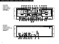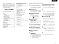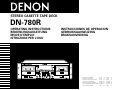
1
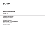
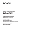
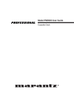
STEREO CASETTE TAPE DECK
DN-780R
OPERATING INSTRUCTIONS
BEDIENUNGSANLEITUNG
MODE D’EMPLOI
ISTRUZIONI PER L’USO
INSTRUCCIONES DE OPERACION
GEBRUIKSAANWIJZING
BRUKSANVISNING
FOR ENGLISH READERS
FÜR DEUTSCHE LESER
POUR LES LECTEURS FRANCAIS
PER IL LETTORE ITALIANO
PARA LECTORES DE ESPAÑOL
VOOR NEDERLANDSTALIGE LEZERS
FOR SVENSKA LÄSARE
PAGE
SEITE
PAGE
PAGINA
PAGINA
PAGINA
SIDA
5
14
23
32
41
50
59
~
~
~
~
~
~
~
PAGE
SEITE
PAGE
PAGINA
PAGINA
PAGINA
SIDA
13
22
31
40
49
58
67
CAUTION
SAFETY INSTRUCTIONS
1.
Read Instructions – All the safety and operating instructions
should be read before the product is operated.
2.
Retain Instructions – The safety and operating instructions
should be retained for future reference.
CAUTION: TO REDUCE THE RISK OF ELECTRIC SHOCK, DO NOT REMOVE COVER
3.
Heed Warnings – All warnings on the product and in the
operating instructions should be adhered to.
(OR BACK). NO USER SERVICEABLE PARTS INSIDE. REFER SERVICING
TO QUALIFIED SERVICE PERSONNEL.
4.
Follow Instructions – All operating and use instructions
should be followed.
The lightning flash with arrowhead symbol, within an equilateral triangle, is intended to
alert the user to the presence of uninsulated “dangerous voltage” within the product’s
enclosure that may be of sufficient magnitude to constitute a risk of electric shock to
persons.
5.
Cleaning – Unplug this product from the wall outlet before
cleaning. Do not use liquid cleaners or aerosol cleaners.
6.
Attachments – Do not use attachments not recommended
by the product manufacturer as they may cause hazards.
7.
Water and Moisture – Do not use this product near water –
for example, near a bath tub, wash bowl, kitchen sink, or
laundry tub; in a wet basement; or near a swimming pool;
and the like.
8.
Accessories – Do not place this product on an unstable cart,
stand, tripod, bracket, or table. The product may fall,
causing serious injury to a child or adult, and serious
damage to the product. Use only with a cart, stand, tripod,
bracket, or table recommended by the manufacturer, or
sold with the product. Any mounting of the product should
follow the manufacturer’s instructions, and should use a
mounting accessory
recommended by the
manufacturer.
RISK OF ELECTRIC SHOCK
DO NOT OPEN
The exclamation point within an equilateral triangle is intended to alert the user to the
presence of important operating and maintenance (servicing) instructions in the literature
accompanying the appliance.
WARNING: TO
PREVENT FIRE OR SHOCK HAZARD, DO NOT EXPOSE THIS
APPLIANCE TO RAIN OR MOISTURE.
CAUTION:
1. Handle the power supply cord carefully
Do not damage or deform the power supply cord. If it is
damaged or deformed, it may cause electric shock or
malfunction when used. When removing from wall outlet,
be sure to remove by holding the plug attachment and not
by pulling the cord.
2. Do not open the top cover
In order to prevent electric shock, do not open the top cover.
If problems occur, contact your DENON dealer.
3. Do not place anything inside
Do not place metal objects or spill liquid inside the cassette
tape deck. Electric shock or malfunction may result.
Please, record and retain the Model name and serial number of
your set shown on the rating label.
Model No. DN-780R
Serial No.
This device complies with Part 15 of the FCC Rules.
Operation is subject to the following two conditions : (1)
This device may not cause harmful interference, and (2) this
device must accept any interference received, including
interference that may cause undesired operation.
This Class B digital apparatus meets all requirements of the
Canadian Interference-Causing Equipment Regulations.
Cet appareil numérique de la classe B respecte toutes les
exigences du Règlement sur le matériel brouilleur du Canada.
9.
A product and cart
combination should be
moved with care. Quick
stops, excessive force,
and uneven surfaces may
cause the product and cart
combination to overturn.
11. Power Sources – This product should be operated only
from the type of power source indicated on the marking
label. If you are not sure of the type of power supply to
your home, consult your product dealer or local power
company. For products intended to operate from battery
power, or other sources, refer to the operating instructions.
12. Grounding or Polarization – This product may be equipped
with a polarized alternating-current line plug (a plug having
one blade wider than the other). This plug will fit into the
power outlet only one way. This is a safety feature. If you
are unable to insert the plug fully into the outlet, try
reversing the plug. If the plug should still fail to fit, contact
your electrician to replace your obsolete outlet. Do not
defeat the safety purpose of the polarized plug.
ANTENNA
LEAD IN
WIRE
GROUND
CLAMP
ANTENNA
DISCHARGE UNIT
(NEC SECTION 810-20)
ELECTRIC
SERVICE
EQUIPMENT
GROUNDING CONDUCTORS
(NEC SECTION 810-21)
GROUND CLAMPS
POWER SERVICE GROUNDING
ELECTRODE SYSTEM
(NEC ART 250, PART H)
NEC - NATIONAL ELECTRICAL CODE
15. Outdoor Antenna Grounding – If an outside antenna or
cable system is connected to the product, be sure the
antenna or cable system is grounded so as to provide some
protection against voltage surges and built-up static
charges. Article 810 of the National Electrical Code,
ANSI/NFPA 70, provides information with regard to proper
grounding of the mast and supporting structure, grounding
of the lead-in wire to an antenna discharge unit, size of
grounding conductors, location of antenna-discharge unit,
connection to grounding electrodes, and requirements for
the grounding electrode. See Figure A.
16. Lightning – For added protection for this product during a
lightning storm, or when it is left unattended and unused
for long periods of time, unplug it from the wall outlet and
disconnect the antenna or cable system. This will prevent
damage to the product due to lightning and power-line
surges.
17. Power Lines – An outside antenna system should not be
located in the vicinity of overhead power lines or other
electric light or power circuits, or where it can fall into such
power lines or circuits. When installing an outside antenna
system, extreme care should be taken to keep from
touching such power lines or circuits as contact with them
might be fatal.
18. Overloading – Do not overload wall outlets, extension
cords, or integral convenience receptacles as this can result
in a risk of fire or electric shock.
10. Ventilation – Slots and openings in the cabinet are provided
for ventilation and to ensure reliable operation of the
product and to protect it from overheating, and these
openings must not be blocked or covered. The openings
should never be blocked by placing the product on a bed,
sofa, rug, or other similar surface. This product should not
be placed in a built-in installation such as a bookcase or rack
unless proper ventilation is provided or the manufacturer’s
instructions have been adhered to.
FIGURE A
EXAMPLE OF ANTENNA GROUNDING
AS PER NATIONAL
ELECTRICAL CODE
13. Power-Cord Protection – Power-supply cords should be
routed so that they are not likely to be walked on or pinched
by items placed upon or against them, paying particular
attention to cords at plugs, convenience receptacles, and
the point where they exit from the product.
19. Object and Liquid Entry – Never push objects of any kind
into this product through openings as they may touch
dangerous voltage points or short-out parts that could
result in a fire or electric shock. Never spill liquid of any
kind on the product.
20. Servicing – Do not attempt to service this product yourself
as opening or removing covers may expose you to
dangerous voltage or other hazards. Refer all servicing to
qualified service personnel.
21. Damage Requiring Service – Unplug this product from the
wall outlet and refer servicing to qualified service personnel
under the following conditions:
a) When the power-supply cord or plug is damaged,
b) If liquid has been spilled, or objects have fallen into the
product,
c) If the product has been exposed to rain or water,
d) If the product does not operate normally by following
the operating instructions. Adjust only those controls
that are covered by the operating instructions as an
improper adjustment of other controls may result in
damage and will often require extensive work by a
qualified technician to restore the product to its normal
operation,
e) If the product has been dropped or damaged in any way,
and
f) When the product exhibits a distinct change in
performance – this indicates a need for service.
22. Replacement Parts – When replacement parts are required,
be sure the service technician has used replacement parts
specified by the manufacturer or have the same
characteristics as the original part.
Unauthorized
substitutions may result in fire, electric shock, or other
hazards.
23. Safety Check – Upon completion of any service or repairs
to this product, ask the service technician to perform safety
checks to determine that the product is in proper operating
condition.
24. Wall or Ceiling Mounting – The product should be mounted
to a wall or ceiling only as recommended by the
manufacturer.
25. Heat – The product should be situated away from heat
sources such as radiators, heat registers, stoves, or other
products (including amplifiers) that produce heat.
2
ENGLISH DEUTSCH
FRANCAIS
FRONT PANEL
FRONTPLATTE
PANNEAU AVANT
PANNELLO FRONTALE
PANEL DELANTERO
VOORPANEEL
FRONT PANELEN
ITALIANO
ESPAÑOL
NEDERLANDS
SVENSKA
!6 !4 !7 !8 !9 @3 @2 @1 @0
!9 !8 !7 !4 !6
q w e r t y u o !1 !22 !3 y t
i !0
REAR PANEL
RÜCKWAND
PANNEAU ARRIERE
IL PANNELLO POSTERIORE
PANEL TRASERO
ACHTERPANEEL
BAKSIDAN
@4 @5 @6 @4 @5 @7 @8 @9 #2
3
#0
#1
e !5
ENGLISH DEUTSCH
FRANCAIS
ITALIANO
• DECLARATION OF CONFORMITY
We declare under our sole responsibility that this
product, to which this declaration relates, is in conformity
with the following standards:
EN60065, EN55013, EN55020, EN61000-3-2 and
EN61000-3-3.
Following the provisions of 73/23/EEC, 89/336/EEC and
93/68/EEC Directive.
• ÜBEREINSTIMMUNGSERKLÄRUNG
Wir erklären unter unserer Verantwortung, daß dieses
Produkt, auf das sich diese Erklärung bezieht, den
folgenden Standards entspricht:
EN60065, EN55013, EN55020, EN61000-3-2 und
EN61000-3-3.
Entspricht den Verordnungen der Direktive 73/23/EEC,
89/336/EEC und 93/68/EEC.
• DECLARATION DE CONFORMITE
Nous déclarons sous notre seule responsabilité que
l’appareil, auquel se réfère cette déclaration, est
conforme aux standards suivants:
EN60065, EN55013, EN55020, EN61000-3-2 et
EN61000-3-3.
D’après les dispositions de la Directive 73/23/EEC,
89/336/EEC et 93/68/EEC.
ESPAÑOL
NEDERLANDS
• DECLARACIÓN DE CONFORMIDAD
Declaramos bajo nuestra exclusiva responsabilidad que
este producto al que hace referencia esta declaración,
está conforme con los siguientes estándares:
EN60065, EN55013, EN55020, EN61000-3-2 y EN610003-3.
Siguiendo las provisiones de las Directivas 73/23/EEC,
89/336/EEC y 93/68/EEC.
SVENSKA
NOTE ON USE / HINWEISE ZUM GEBRAUCH /
OBSERVATIONS RELATIVES A L’UTILISATION / NOTE SULL’USO
NOTAS SOBRE EL USO / ALVORENS TE GEBRUIKEN / OBSERVERA
• EENVORMIGHEIDSVERKLARING
Wij verklaren uitsluitend op onze verantwoordelijkheid
dat dit produkt, waarop deze verklaring betrekking heeft,
in overeenstemming is met de volgende normen:
EN60065, EN55013, EN55020, EN61000-3-2 en
EN61000-3-3.
Volgens de bepalingen van de Richtlijnen 73/23/EEC,
89/336/EEC en 93/68/EEC.
• ÖVERENSSTÄMMELSESINTYG
Härmed intygas helt på eget ansvar att denna produkt,
vilken detta intyg avser, uppfyller följande standarder:
EN60065, EN55013, EN55020, EN61000-3-2 och
EN61000-3-3.
Enligt stadgarna i direktiv 73/23/EEC, 89/336/EEC och
93/68/EEC.
• DICHIARAZIONE DI CONFORMITÀ
Dichiariamo con piena responsabilità che questo
prodotto, al quale la nostra dichiarazione si riferisce, è
conforme alle seguenti normative:
EN60065, EN55013, EN55020, EN61000-3-2 e EN610003-3.
In conformità con le condizioni delle direttive 73/23/EEC,
89/336/EEC e 93/68/EEC.
QUESTO PRODOTTO E’ CONFORME
AL D.M. 28/08/95 N. 548
• Avoid high temperatures.
Allow for sufficient heat dispersion when
installed on a rack.
• Vermeiden Sie hohe Temperaturen.
Beachten Sie, daß eine ausreichend
Luftzirkulation gewährleistet wird, wenn das
Gerät auf ein Regal gestellt wird.
• Eviter des températures élevées
Tenir compte d’une dispersion de chaleur
suffisante lors de l’installation sur une
étagère.
• Evitate di esporre l’unità a temperature alte.
Assicuratevi che ci sia un’adeguata
dispersione del calore quando installate
l’unità in un mobile per componenti audio.
• Evite altas temperaturas
Permite la suficiente dispersión del calor
cuando está instalado en la consola.
• Vermijd hoge temperaturen.
Zorg voor een degelijk hitteafvoer indien het
apparaat op een rek wordt geplaatst.
• Undvik höga temperaturer.
Se till att det finns möjlighet till god
värmeavledning vid montering i ett rack.
CAUTION
• The ventilation should not be impeded by covering the ventilation openings with items, such as newspapers, table-cloths,
curtains, etc.
• No naked flame sources, such as lighted candles, should be placed on the apparatus.
• Please be care the environmental aspects of battery disposal.
• The apparatus shall not be exposed to dripping or splashing for use.
• No objects filled with liquids, such as vases, shall be placed on the apparatus.
• FOR CANADA MODEL ONLY
CAUTION
TO PREVENT ELECTRIC SHOCK, MATCH WIDE BLADE
OF PLUG TO WIDE SLOT, FULLY INSERT.
4
• POUR LES MODELE CANADIENS
UNIQUEMENT
ATTENTION
POUR ÉVITER LES CHOCS ÉLECTRIQUES,
INTERODUIRE LA LAME LA PLUS LARGE DE LA FICHE
DANS LA BORNE CORRESPONDANTE DE LA PRISE ET
POUSSER JUSQU’ AU FOND.
• Handle the power cord carefully.
Hold the plug when unplugging the cord.
• Gehen Sie vorsichtig mit dem Netzkabel um.
Halten Sie das Kabel am Stecker, wenn Sie
den Stecker herausziehen.
• Manipuler le cordon d’alimentation avec
précaution.
Tenir la prise lors du débranchement du
cordon.
• Manneggiate il filo di alimentazione con cura.
Agite per la spina quando scollegate il cavo
dalla presa.
• Maneje el cordón de energía con cuidado.
Sostenga el enchufe cuando desconecte el
cordón de energía.
• Hanteer het netsnoer voorzichtig.
Houd het snoer bij de stekker vast wanneer
deze moet worden aan- of losgekoppeld.
• Hantera nätkabeln varsamt.
Håll i kabeln när den kopplas från el-uttaget.
• Keep the set free from moisture, water, and
dust.
• Halten Sie das Gerät von Feuchtigkeit,
Wasser und Staub fern.
• Protéger l’appareil contre l’humidité, l’eau et
lapoussière.
• Tenete l’unità lontana dall’umidità, dall’acqua
e dalla polvere.
• Mantenga el equipo libre de humedad, agua
y polvo.
• Laat geen vochtigheid, water of stof in het
apparaat binnendringen.
• Utsätt inte apparaten för fukt, vatten och
damm.
• Unplug the power cord when not using the
set for long periods of time.
• Wenn das Gerät eine längere Zeit nicht
verwendet werden soll, trennen Sie das
Netzkabel vom Netzstecker.
• Débrancher le cordon d’alimentation lorsque
l’appareil n’est pas utilisé pendant de
longues périodes.
• Disinnestate il filo di alimentazione quando
avete l’intenzione di non usare il filo di
alimentazione per un lungo periodo di tempo.
• Desconecte el cordón de energía cuando no
utilice el equipo por mucho tiempo.
• Neem altijd het netsnoer uit het stopkontakt
wanneer het apparaat gedurende een lange
periode niet wordt gebruikt.
• Koppla ur nätkabeln om apparaten inte
kommer att användas i lång tid.
* (For sets with ventilation holes)
• Do not obstruct the ventilation holes.
• Die Belüftungsöffnungen dürfen nicht
verdeckt werden.
• Ne pas obstruer les trous d’aération.
• Non coprite i fori di ventilazione.
• No obstruya los orificios de ventilación.
• De ventilatieopeningen mogen niet worden
beblokkeerd.
• Täpp inte till ventilationsöppningarna.
• Do not let foreign objects in the set.
• Keine fremden Gegenstände in das Gerät
kommen lassen.
• Ne pas laisser des objets étrangers dans
l’appareil.
• E’ importante che nessun oggetto è inserito
all’interno dell’unità.
• No deje objetos extraños dentro del equipo.
• Laat geen vreemde voorwerpen in dit
apparaat vallen.
• Se till att främmande föremål inte tränger in i
apparaten.
• Do not let insecticides, benzene, and thinner
come in contact with the set.
• Lassen Sie das Gerät nicht mit Insektiziden,
Benzin
oder
Verdünnungsmitteln
in
Berührung kommen.
• Ne pas mettre en contact des insecticides,
du benzène et un diluant avec l’appareil.
• Assicuratevvi che l’unità non venga in
contatto con insetticidi, benzolo o solventi.
• No permita el contacto de insecticidas,
gasolina y diluyentes con el equipo.
• Laat geen insektenverdelgende middelen,
benzine of verfverdunner met dit apparaat in
kontakt komen.
• Se till att inte insektsmedel på spraybruk,
bensen och thinner kommer i kontakt med
apparatens hölje.
• Never disassemble or modify the set in any
way.
• Versuchen Sie niemals das Gerät
auseinander zu nehmen oder auf jegliche Art
zu verändern.
• Ne jamais démonter ou modifier l’appareil
d’une manière ou d’une autre.
• Non smontate mai, nè modificate l’unità in
nessun modo.
• Nunca desarme o modifique el equipo de
ninguna manera.
• Nooit dit apparaat demonteren of op andere
wijze modifiëren.
• Ta inte isär apparaten och försök inte bygga
om den.
ENGLISH
Thank you very much for purchasing the DENON
component stereo cassette tape deck.
DENON proudly presents this advanced tape deck to
audiophiles and music lovers as a further proof of
DENON’s non-compromising pursuit of the ultimate in
sound quality. The high quality performance and easy
operation are certain to provide you with many hours
of outstanding listening pleasure.
— TABLE OF CONTENTS —
FEATURES ………………………………………………5
NAMES AND FUNCTIONS OF PARTS …………5 ~ 7
CASSETTE TAPES………………………………………8
AUTOMATIC TAPE SELECTION………………………8
PLAYBACK……………………………………………8, 9
RELAY PLAY ………………………………………8
TWIN OUTPUT ……………………………………8
MUSIC SEARCH SYSTEM ………………………8
POWER ON PLAYBACK …………………………9
RECORDING ………………………………………9, 10
PROPER RECORDING LEVEL ……………………9
REC/REC MUTE AND REC PAUSE BUTTON …9
AUTO-STANDBY …………………………………10
TWIN RECORDING ………………………………10
RELAY RECORDING ……………………………10
SYNCHRONIZED OPERATION …………………10
DUBBING………………………………………………11
MANUAL DUBBING ……………………………11
MEMORY STOP ………………………………………11
PRESET FUNCTION …………………………………11
DOLBY B AND C NOISE REDUCTION SYSTEM …12
DOLBY HX-PRO HEADROOM
EXTENSION SYSTEM ………………………………12
MAINTENANCE ………………………………………12
TROUBLESHOOTING ………………………………13
SPECIFICATIONS ……………………………………13
Please check to make sure the following items are
included with the main unit in the carton:
(1) Operating Instructions…………………………1
(2) Operating Instructions (Applications) ………1
(3) Connection Cords………………………………4
(4) Service Station List ……………………………1
NAMES AND FUNCTIONS OF PARTS
q
Power Operation Switch (POWER)
w
Master/Slave Switch
FEATURES
2 19-inch Rack Mountable
2 Independent Input/Output
2 Dolby B & C Noise Reduction Systems
(A/B Independent)
2 Dolby HX-Pro Headroom Extension System
2 Twin Recording and Relay Recording
2 Relay Playback
2 TS MIC Jacks on Front Panel
2 Cascade Recording and Playback
2 Synchronized Recording
2 RS232C Serial Control Port
2 Parallel Remote Control
2 2-Speed Dubbing
2 Quick Auto Reverse
2 Speed Control of Approximately ±12%
(A/B Independent)
2 Computer Controlled Mechanism
2 Computing Tape Counter with 4-Digit Readout and
Memory Stop
2 Music Search System
2 FL Peak Level Meters
2 Auto Tape Selector
2 Memory Back-up
2 Auto-standby
2 XLR Input/Output Kit (Option)
(Model Name :ACD-780)
e
Press once to turn the power on, and once more
to turn the power off.
The deck remains in a stand-by (non-operative)
mode for approximately 2 seconds after it is
switched on.
For normal operation, set this to “OFF”.
Set the switch to “MASTER” or “SLAVE” when
using the DN-780R together with other DN780Rs.
!0
!1
Dubbing Speed Buttons
(DUBBING SPEED)
Pressing the NORMAL button starts regular
speed dubbing from deck A to deck B. Press the
HIGH button to perform dubbing at double
speed. See page 11.
Tape Speed Control (TAPE SPEED)
y
Input Level Control (INPUT LEVEL)
u
Headphone Level Control
i
Use this knob to vary the tape speed. The speed
can be varied within a range of approximately
±12% according to the position of the tape
speed control knob.
!2
Use this to adjust the output level of the
headphones.
Use this to select the headphone’s output signal.
Auto Gain Control Switch of Mic
(MIC AGC)
Microphone Jacks (MIC)
Connect the microphone to this jack for
microphone mixed recording.
MIC signals will be mixed with the line input
signals.
Accepts an unbalanced (TS Type) microphone
with 1/4” mono jacks.
When a microphone is only connected to the
L/MONO jack, the recording will be monaural.
Connect to both the L and R jacks for stereo
recording.
NOTE :
To prevent noise, set the MIC MODE switch !2
to “off” when connecting microphones to the
MIC jacks.
This knob adjusts the recording input level. It
affects the level in both channels. See page 9.
Headphone Select Switch
(PHONES SELECT)
For private music enjoyment without disturbing
others, or for monitoring a recording, a
headphone set may be connected to this jack.
Use a headphone with an impedance rating of 8
to 1200 Ω/ohms. Signal are output according to
the position of the PHONES SELECT switch i.
OFF : The level is adjusted with the MIC LEVEL
control !3.
ON : The level is adjusted automatically according
to the level of the microphone input signal.
Select the Dolby NR type that suits the
recording.
t
Headphone Jack (PHONES)
Selects the microphone level adjustment
method.
Dolby NR Switch (DOLBY NR)
OFF : Recording without Dolby NR
B:
Recording with Dolby NR type B
(The “ ” indicator will light up.)
C:
Recording with Dolby NR type C
(The “
” indicator will light up.)
r
o
!3
Microphone Mode Switch (MIC MODE)
OFF : Turns the microphone input off.
LINE : When in the tape play, record or
recording pause mode, the sound input
to the microphone is output from the
LINE OUT jack. The sound input to the
microphone is not recorded.
REC : Microphone mixed recording is performed.
Microphone Input Level Control
(MIC LEVEL)
Adjust the level of the Microphone inputs.
A:
The Deck A’s signals are output to the
headphones.
MIX : The MIX signals of Deck A and Deck B are
output to the headphones.
B:
The Deck B’s signals are output to the
headphones.
5
ENGLISH
!4
@2
Tape Transport Buttons
0 ,1
Play Button
Press to playback tape.
2
Stop Button
Press to stop the tape in any mode.
6
Fast Rewind Button
Press for fast rewind.
7
Fast Forward Button
Press for fast forwarding.
Rec/Rec Mute Button
Press the Rec/Rec Mute button ( 4 ) and Play button ( 0 , 1 )
simultaneously to start recording. If only the Rec/Rec Mute
button ( 4 ) is pressed, the deck enters the recording pause
mode. Pressing this button in the recording pause mode will
start Auto Rec Mute, and a 5-second silent space is recorded
onto the tape. See page 9.
Display
Reverse Mode Indicator
Deck A Tape Counter
Deck A Peak Level Meter
4
3
Rec Pause Button
Press this button to enter the recording pause mode from the
recording or recording mute mode. This button can only be used
during recording. See page 9.
Deck B Tape Counter
Deck B Peak Level Meter
Deck A Dolby NR
Indicator
Deck B Dolby NR
Indicator
Deck A Memory
Indicator
Deck B Memory
Indicator
• Synchronized Indicator
• Infrared Remote
Control Indicator
Deck A
Tape Transport
Indicator
Twin Rec
Indicator
Lights when deck B is
selected with the RC IN
control jack.
Deck B
Tape Transport
Indicator
Dubbing Speed Indicator
Lights when deck A is selected with the RC IN control jack.
!5
Input Select Switch of Deck B
(INPUT SELECT)
!9
Select the audio input to the Deck B (DECK A,
LINE A, LINE B).
!6
!7
Cassette Compartment Cover
If the cover is not closed completely, the tape
transport buttons will remain inoperative.
Counter Memory Button
(COUNTER MEMO)
When this button is pressed during forward tape
travel ( 1 ), fast rewinding ( 6 ) will stop
automatically at the tape counter position
“‚‚‚‚”.
When this button is pressed during reverse tape
travel ( 0 ), fast forwarding ( 7 ) will stop
automatically at the tape counter position
“‚‚‚‚”. See page 11.
!8
@0
@1
Eject Button ( 5 )
Press this button to open the cassette
compartment cover. When the tape is running,
press the Stop ( 2 ) button first to stop tape
transport, then press the Eject ( 5 ) button.
@3
Select the type of tape transport. The reverse
mode can be set to
(one side),
(continuous playback), RELAY (relay playback),
CASCADE (continuous recording/playback on
multiple units is possible).
@4
Twin Recording Button (TWIN REC)
@5
Cascade Control Jacks (CASCADE)
Deck A, B Line Input Jacks (LINE IN)
These are unbalanced inputs using RCA type
jacks.
Use them to input signals to be recorded on a
tape.
#0
Serial Control Port (RS232C)
Deck A, B Line Output Jacks
(LINE OUT)
Connect these for continuous operation on
multiple units.
When the REV. MODE button @0 is set to
“CASCADE”, the start signal is output from this
output jack once operation of Deck B is finished.
This is serial remote connector.
Applicable connector : 9-pin D-sub (male)
Baud rate : 9600 bps
Pin layout
Pin No.
1
These are unbalanced outputs using RCA type
jacks.
@6
Counter Reset Button
(COUNTER RESET)
Press this button to reset the tape counter to
zero.
@7
Deck A Line Output Select Switch
(DECK A OUTPUT SEL.)
@8
6
2
7
Selects the signal to be output from the Deck A
output jacks.
3
A:
The Deck A signal is output.
A+B : Both the Deck A and Deck B signals are
output.
4
Deck A Line Input Through Jacks
(THRU)
The signal input to the DECK A LINE IN jacks is
output unchanged.
External Synchronized Control Jacks
(EXT. SYNC.)
Connect these for synchronized recording.
6
@9
This sensor receives the infrared light transmitted
from the wireless remote control unit.
This product dose not come with remote control
unit.
Reverse Mode Button (REV. MODE)
Pressing this button will set both deck A and B
to the recording pause mode. See page 10.
Remote Control Sensor
(REMOTE SENSOR)
I/O
_
NC
_
TxD
O
_
NC
RxD
8
9
5
GND
Signal Name
NC
I
_
NC
_
NC
_
S. GROUND
_
ENGLISH
#1
#2
Parallel Remote Control Port
(PARALLEL)
This is a parallel remote connector.
Applicable connector : 25-pin D-sub (male)
Connecting signal layout
RC IN control Jack
This is a stereo mini jack for wired remote control.
1. Circuit Diagram
R001
R002
200 Ω/ohms 30 Ω/ohms
NOTE : All input is active low.
Pin No.
1
I/O
_
Signal Name
FG
15
3
16
4
17
5
18
6
19
7
TWIN REC
I
A COUNTER RESET
I
A REWIND
I
B COUNTER MEMO
I
B FAST FORWARD
I
REVERSE MODE
I
DUBBING HIGH
I
B REC
I
B REWIND
I
A REC PAUSE
I
A PLAY FORWARD
I
I/O
Signal Name
20
_
14
2
Pin No.
A STOP
8
21
9
22
10
23
11
24
12
25
13
I
L _ CH
A PLAY REVERSE
I
DUBBING NORMAL
I
A REC
Command common
I
_
B COUNTER RESET
I
R _ CH
B REC PAUSE
I
φ3.5 STEREO MINI PLUG
B PLAY FORWARD
I
B STOP
I
B PLAY REVERSE
I
A FAST FORWARD
I
A COUNTER MEMO
I
SW101
B RESET
13
12
11
9
10
8
7
6
5
4
3
2
1
A6
B7
SW003
STOP
PAUSE
F _ PLAY
SW004
SW005
FF
REW
SW006
SW007
REC/
REC MUTE
R _ PLAY
SW008
DECK A/B
GND
L-CH : Vcc (5 VOLT)
R-CH : SIGNAL
GND
SW001 ~ 008 : Momentary Contact
SW101, 102 : Toggle Switch
SW 008 DECK A/B
DECK SELECTOR button
Press this button to select either
Deck A or Deck B to be controlled.
2. Operation with Parallel Connections
A number of DN-780R units can be simultaneously operated in parallel with 1 button.
Operation with parallel connections can be used with a maximum of 5 units.
Connection of 6 or more units will lead to indicator operation.
3. Cable Length
The longer the length of the cable, the more susceptible the system will be to the effects of external noise.
Keep cable lengths to 2 m or less.
Do not locate equipment that produces electrical noise in the vicinity of the cable.
Doing so might lead to incorrect operation due to the noise.
25
24
23
22
21
20
19
18
17
16
15
DUBBING HIGH
SW002
• Do not connect the left channel of the plug (Vcc) with R001 (200 Ω/ohms) in the second and subsequent units.
• Use resistors having a tolerance of with ±5%.
Use of resistors having a poorer tolerance will cause incorrect operation.
• Never short circuit the left-channel line (Vcc). Doing so will damage the main unit.
9
22
22
11
22
10
B6
SW001
SW102
A4
A1
A0
R004
R005
R006
R007
R008
62 Ω/ohms 110 Ω/ohms 160 Ω/ohms 270 Ω/ohms 560 Ω/ohms
Second and Subsequent Units
Use the connection example in the diagram below as reference for connecting a parallel remote controller
to the DN-780R.
B1
First Unit
R003
43 Ω/ohms
TWIN REC
22
2
5. Pressing more than one button of the wired remote control box at the same time (for combined operations)
is not possible.
A music search operation will not result from pressing the Play (1) and Fast Forward (7), or Play (0) and
Rewind (6) buttons at the same time.
12
22
B0
21
22
DUBBING NORMAL
23
22
24
22
13
B3
B2
25
3
22
A MEMO
22
4
22
A7
15
16
A RESET
22
5
22
22
17
22
18
B MEMO
22
6
22
7
22
22
19
22
REV. MODE
B4
A3
20
22
A2
8
22
4. Do not disconnect or connect the remote control plug during operation of the unit.
The pins of the plug might cause a short circuit of the pins inside the jack which can stop the operation.
6. Pressing a button of the wired remote control box and a button of the main unit, DN-780R, (for combined
operations) is not possible.
Note on Connecting the Remote Control Box
When multiple sets are connected to a single remote control box, the other sets may operate erroneously
when this set’s power is turned on off or when the cord is connected or disconnected from the remote control
jack.
Turn off the remote control box’ toggle switched (SW101, 102, ...) when turning this set’s power on or off or
when connecting or disconnecting the cord from the remote control jack while other sets are connected to the
remote control box.
7
ENGLISH
CASSETTE TAPES
2 Handling Precautions
• C-120 cassette tapes
C-120 cassette tapes are not recommended as
they use a very thin tape base which may become
tangled around the capstan or pinch roller.
• Tape Slack
Before putting a tape into the deck, take up any
slack with a pencil or your finger tip. This
precaution prevents the tape from becoming
entangled around the capstan or pinch roller.
A
PLAYBACK
2 Storage Precautions
• Do not store cassette tapes in a place where they
will be subject to:
• Extremely high temperature or excessive
moisture
• Excessive dust
• Direct sunlight
• Magnetic fields (near TV sets or speakers)
• To eliminate tape slack, store your cassettes in
cassette cases with hub stops
2 Accidental Erasure Prevention
• All cassettes have erasure prevention tabs for each
side. To protect valuable recordings from accidental
or inadvertent erasure, remove the tab for the
appropriate side with a screwdriver or another tool.
• To record on a tape whose erasure prevention tabs
have been removed, cover the tab holes with
adhesive tape.
• The operations described below apply to deck A
and deck B alike.
• The numbers in the illustration below depict the
order in which operation steps are carried out.
q Press the POWER switch q to the ON ( ¢ )
position.
w Press the Eject ( 5 ) button !9 to open the cassette
compartment cover !6.
e Load the cassette tape and close the cassette
compartment cover !6.
r When listening to a tape that has been recorded
with Dolby noise reduction, set the DOLBY NR
switch e to match the system used at the time of
recording.
t Select the type of tape transport with the REV.
MODE button @0.
Mode
Indicator
To listen to one side only
To listen to repeat playback of
both sides
To listen to continuous playback
of both sides and both decks.
Erasure prevention tab for
side A
Erasure prevention tab for side B
AUTOMATIC TAPE SELECTION
This Stereo Cassette Deck contains an automatic tape
selector which automatically selects the optimum
bias and equalization for the tape in use.
This is accomplished by detection of the tape type
detections holes in the cassette housing.
• If a tape without tape type detection holes is
used, the deck will be set for normal tapes.
Detection holes
for metal tape
Detection holes
for chrome tape
8
RELAY
or
CASCADE
y Press the Play ( 0 or 1 ) button !4 to begin
playback. The Play ( 0 or 1 ) indicator will light
during playback.
u Press the Stop ( 2 ) button !4 to stop the playback.
• If different types of Dolby noise reduction are
used for record and playback, playback response
will be adversely effected.
• When power is turned off during tape transport,
it may not be possible to remove the cassette
by pressing the Eject ( 5 ) button !9.
In this case, turn on power again before you
press the Eject ( 5 ) button !9.
2 RELAY PLAY (continuous playback of the tapes
in deck A and deck B)
• Load a cassette tape into deck A and B, and set the
DOLBY NR switch correctly on deck A and B.
• In the relay play mode, the Deck A and Deck B play
signals are output from the DECK A LINE OUT
jacks.
q REV. MODE button @0 set to “RELAY”.
w Press the Play ( 0 or 1 ) button !4 of the deck
you first wish to listen to. The Play ( 0 or 1 )
indicator of the deck playing back the tape will
light up.
e To stop relay play, press the Stop ( 2 ) button !4
of the deck currently playing the tape.
• The number of cycles for relay playback can be
selected (1, 5 or 10).
For details, refer to “PRESET FUNCTION”
(page 11). When playback starts from deck B,
when switching to deck A, the first deck A
playback cycle will be counted as the second
cycle. The completion of cycles will always be
at the opposite side of the tape in deck B.
• If the playback deck has been switched, be
sure to start playback in the forward direction
(1).
NOTE :
In the relay play mode, it is not possible to perform
the play operations simultaneously on Decks A and
B. If one of the decks is set to the play mode while
the other deck is already in the play mode, playback
is performed on the deck that has just been set to
the play mode and stops on the other deck.
2 TWIN OUTPUT
With the DN-780R, it is possible to play tapes
simultaneously on decks A and B and output their
signals at the same time.
When both decks A and B are played, the signals for
deck A are output from the DECK A LINE OUT jacks,
and the signals from deck B are output from the DECK
B LINE OUT jacks..
• The DECK B LINE OUT jacks are exclusively for the
deck B signals.
• The DECK A LINE OUT jacks are for both the deck
A and deck B signals when deck A line output
select switch set to “A+B”.
• Use the DECK A LINE OUT jacks when connecting
one of the sets of line outputs to a receiver or
amplifier.
ENGLISH
2 MUSIC SEARCH SYSTEM
The music search system detects blank sections
(lasting for at least 4 seconds) between selections in
order to locate the beginning of selections in the
forward or reverse direction.
1. To advance from the current selection to the
beginning of the next selection (CUE) :
Press the Play ( 1 ) button simultaneously with
the Fast Forward ( 7 ) button. Press the Play
( 0 ) button simultaneously with the Rewind
( 6 ) button.
The deck will skip the rest of the current selection
and automatically resume play from the beginning
of the next selection.
2. To repeat playback from the beginning of the
current selection (REVIEW) :
Press the Play ( 1 ) button simultaneously with
the Rewind ( 6 ) button. Press the Play ( 0 )
button simultaneously with the Fast Forward
( 7 ) button.
The deck will rewind the tape to the beginning of
the current selection and automatically resume
play from that point.
This is very convenient for repeating playback of
the current selection.
Notes on Music Search Operation :
The search functions operates by detecting
comparatively long, blank sections approximately 4 to
5 seconds long, in between recorded selections.
Therefore, the system may not operate normally in
the following cases:
• Recordings with discontinuous speech or
conversation.
• Recordings with long periods of pianissimo (softly
played music).
• Blank sections with a high level of noise.
• Blank sections shorter than 4 seconds.
• If noise-emitting appliances, such as electric razors,
drills, refrigerators, etc., are operated nearby.
• REVIEW close to the beginning of the program or
CUE close to the ending.
2 POWER ON PLAYBACK
Playback starts automatically when the power is
turned on.
• Playback is performed according to the reverse
mode set when the power was turned off.
• Playback is performed even if a cassette tape is
only loaded in one deck.
• Playback always starts in the “1” tape travel
direction.
• When tapes are loaded in both Deck A and Deck B,
playback starts from Deck A.
• The power on playback function can be set with
the “PRESET FUNCTION” (page 11).
RECORDING
• The operations described below apply to deck A
and deck B alike.
q Press the POWER switch q to the ON ( ¢ )
position.
w Load the cassette tape !9, !6.
(Check that the erasure prevention tabs of the
cassette housing have not been broken off.)
e Select the Dolby NR type that suits the recording.
r Select the type of tape transport with the REV.
MODE button @0.
Mode
Indicator
To record on only one side
To continuously record on both
sides
,
RELAY
or
CASCADE
t Press the Rec/Rec Mute ( 4 ) button !4 to set the
recording pause mode. The 4 3 indicator will light
up.
y Adjust the recording level with the INPUT LEVEL
control y while watching the Peak Level Meter.
u Recording starts when the Play ( 0 or 1 ) button
!4 for the direction indicated by the flashing tape
travel indicator ( 0 or 1 ) is pressed. If the other
Play ( 0 or 1 ) button !4 is pressed, the direction
of tape travel changes.
The Play ( 0 or 1 ) and the 4 indicator will light
during recording.
i To stop recording, press the Stop ( 2 ) button !4.
o To pause the recording, press the Rec Pause ( 3 )
button !4. Press the Play ( 0 or 1 ) button !4 to
resume recording.
NOTE :
For Deck B, the input source can be selected.
Select the desired line input beforehand using the
INPUT SELECT switch.
DECK A : The sound playing on Deck A can be
recorded. (Refer to “MANUAL DUBBING”
(page 11)).
LINE A : The sound input to the DECK A LINE IN
jacks can be recorded.
LINE B : The sound input to the DECK B LINE IN
jacks can be recorded.
Caution :
Be careful not to erase important recordings by
mistake. Inadvertent start of recording will happen
in the following cases:
1. If the Play ( 0 or 1 ) button is pressed while the
4 indicator lights, recording starts.
2. If the Play ( 0 or 1 ) button and Rec/Rec Mute
( 4 ) button are pressed at the same time,
recording starts.
The best way to avoid accidental erasure is to break
off the two erasure prevention tabs on the cassette
housing.
2 PROPER RECORDING LEVEL
A too high recording level can saturate the tape and
cause distortion. On the other hand, if the recording
level is set too low, soft passages will be marked by
residual noise. A proper recording level is the most
important factor for making well balanced recordings.
Guideline for maximum recording level
Type I (Normal)
+3 dB level on peaks
Type II (CrO2)
+3 dB level on peaks
Type IV (Metal)
+3 dB level on peaks
Note :
The optimum recording level differs depending on
the program source and the type of tape used.
2 REC/REC MUTE AND REC PAUSE BUTTONS
1. To record a 5-second blank section during
recording:
Press the Rec/Rec Mute ( 4 ) button. A 5-second
blank will be recorded and the deck will enter the
recording standby mode.
2. To record a 5-second blank section during the
recording standby mode:
Press the Rec/Rec Mute ( 4 ) button from the
recording standby mode. A 5 second blank will be
recorded and the deck will enter the recording
standby mode again.
3. To cancel recording of blank space:
Press the Rec Pause ( 3 ) button. Blank space
recording will be cancelled and the deck enters
the recording standby mode.
4. To extend the blank section with another 5
seconds or more:
Simply press the Rec/Rec Mute ( 4 ) button and
the blank section will be increased with another 5
seconds.
9
ENGLISH
2 AUTO-STANDBY
This function is extremely convenient when conducting
relay recording, relay playback, twin recording or tape
copying.
• When the Fast Rewind ( 6 ) and Rec Pause ( 3 )
buttons are pressed simultaneously while in the
stop mode and the tape is set to play in the forward
direction ( 1 ), the tape is rewound to the
beginning, then played to the end of the leader
tape and stopped automatically at the beginning of
the magnetic tape.
• When the Fast Forward ( 7 ) and Rec Pause ( 3 )
buttons are pressed simultaneously while in the
stop mode and the tape is set to play in the reverse
direction ( 0 ), the tape is fast-forwarded to the
end, then played in the reverse direction to the end
of the leader tape and stopped automatically at the
beginning of the magnetic tape.
• The Play ( 0 or 1 ) indicator flashes during the
auto-standby mode.
Caution :
If recording is started after using the auto standby
function with a recorded tape, the sound of the
previous recording may not be completely erased.
In such cases, rewind the tape before starting to
record.
10
2 TWIN RECORDING (simultaneous recording on
deck A and deck B)
This is a convenient feature for recording the same
program source onto two tapes at the same time.
• This function records the source input to the DECK
A LINE IN jacks.
• Input the source you want to record to the DECK A
LINE IN jacks.
• Load cassette tapes into both deck A and B. Set
the DOLBY NR switch (Deck A only) and REV.
MODE button.
• In the twin recording mode, only the recording
monitor signal of the DECK A LINE OUT jacks is
output.
q Press the TWIN REC button @1. The
indicator will light up and both decks will enter the
recording pause mode.
w Adjust the INPUT LEVEL-A control y for the best
recording input levels while watching the Peak
Level Meter.
e Press the Play ( 0 or 1 ) button !4 (deck A or B)
to start twin recording.
r To stop twin recording, press the Stop ( 2 ) button
!4 of each deck.
• By pressing the both deck A and B Rec Pause ( 3 )
button !4, the recording pause or recording mute
mode on both decks can be set automatically.
• To set the twin recording mute mode from the twin
recording pause mode, press the Rec/Rec Mute
(4) button on both deck A and B for at least 0.5
seconds.
• The relay or cascade mode cannot be set with the
REV. MODE button when in the twin recording
mode.
2 RELAY RECORDING (continues recording from
deck A to deck B)
To record a long program, start recording on deck A,
and when both sides of the tape in deck A have been
recorded, the relay recording feature continues to
record on the tape in deck B.
• This function records the source input to the DECK
A LINE IN jacks.
• Load cassette tapes into decks A and B, and set
the DOLBY NR switch both deck A/B.
q REV. MODE button @0 set to “RELAY”.
The RELAY indicator will light.
Recording Order
Deck A
Side facing you
/ Opposite side
Deck B
Side facing you
/ Opposite side
w Adjust the INPUT LEVEL control y of both deck A
and B for the best recording input level while
watching the Peak Level Meter.
e Press the Rec/Rec Mute ( 4 ) button !4 of deck A
to set the recording pause mode.
r Press the Play ( 0 or 1 ) button !4 of deck A to
start relay recording.
t To stop relay recording, press the Stop ( 2 ) button
!4 of the deck that is recording.
If recording has been switched from Deck A to
Deck B, be sure to start recording in the forward
direction (1).
NOTE :
In the relay recording mode, it is not possible to
perform the recording operations simultaneously on
Decks A and B. Nothing happens if the recording
operation is performed on one of the decks while
the other deck is already in the recording mode.
2 SYNCHRONIZED OPERATION
• The synchro function can be used when the DN780R is used together with a Denon product
equipped with an EXT. SYNC. IN/OUT jack.
• Twin recording in sync with another DN-780R is
possible.
• Use a single RCA cable to connect the units’ EXT.
SYNC. OUT jacks with the units’ EXT. SYNC. IN
jacks.
q Press the TWIN REC button @1 on one of the
units.
The twin recording command is output from the
EXT. SYNC. OUT jack and the other unit is set to
the twin recording mode.
w Press the Play ( 0 or 1 ) button !4 on one of the
units.
The play command is output from the EXT. SYNC.
OUT jack and twin recording also starts on the
other unit.
e Press the Stop ( 2 ) button !4 on one of the units.
The stop command is output from the EXT. SYNC.
OUT jack and the other unit is also set to the stop
mode.
ENGLISH
DUBBING (from deck A to deck B)
q Press the POWER switch q to the ON ( ¢ )
position.
w Load the cassette tape to be played in deck A and
the one to be recorded in deck !9, !6.
e Select the type of tape transport with the REV.
MODE button @0.
Reverse
mode
Operation
Dubbing is performed only for one
side.The decks stop when either
deck A or B reaches the end of the
tape.
The tape direction is reversed on
each deck when they reach the end
of the tape. (This is convenient for
dubbing to a tape with a different
length.)
RELAY
or
CASCADE
During dubbing of the side facing
you, the deck that first reaches the
end of the tape will stand by until the
other deck reaches the end of the
tape, then both decks will reverse
the tape direction together.
(Depending on the manufacturer, the
length of tapes having the same
recording time may differ somewhat.
Setting this mode permits the
arrangement of the beginning portion
of the opposite side of the tape.)
r To begin normal speed dubbing, press the
DUBBING SPEED NORMAL button r. The DUB
indicator will light at this time.
To high speed dubbing, press the DUBBING
SPEED HIGH button r.
The HIGH indicator will light at this time.
t To stop dubbing, press the Stop ( 2 ) button !4 of
deck A or deck B.
MEMORY STOP
• When dubbing, the recording level and the Dolby
NR coding will be the same as those of the
playback tape, regardless of the positions of the
INPUT LEVEL control and the DOLBY NR switch.
• When listening to the playback sound during
normal speed dubbing, set the DOLBY NR switch
to match the Dolby NR system with which the
playback tape was recorded. This will assure
correct sound reproduction, but does not affect the
recording.
• The playback sound cannot be heard during high
speed dubbing.
• Operation using the Rec/Rec Mute ( 4 ) and Rec
Pause ( 3 ) buttons of deck B is permitted during
normal speed dubbing.
• Buttons other than the Stop ( 2 ) button cannot be
used during high speed dubbing.
• In the normal speed dubbing mode, play signals are
only output from the DECK A LINE OUT jacks. In
the high speed dubbing mode, no sound is output.
2 MANUAL DUBBING
• With this function, the signal played on Deck A can
be recorded manually on the tape in Deck B.
• The manual dubbing function is also used to record
the signal of the Deck A tape with which the
microphone input signal has been mixed onto the
tape in Deck B.
q Perform steps e to t in the “PLAYBACK”
section on Deck A.
w Perform steps w to t in the “RECORDING”
section on Deck B. Set to Deck B INPUT SELECT
switch to Deck A.
e Set deck A to the play mode and adjust the
recording level using the INPUT LEVEL-B control
y.
r Connect microphones to the MIC jacks !1 and set
the MIC MODE switch !2 to the “REC” mode.
t Set the microphone input level with the MIC
INPUT LEVEL control !3. Also set the MIC AGC
switch !0 to “ON”.
y Start playback on Deck A and recording on Deck
B.
NOTE :
This operation is not possible if the reverse mode is
set to RELAY or CASCADE.
To prevent noise, set the MIC MODE switch to
“off” when connecting microphones to the MIC
jacks.
1. MEMORY STOP Operation
(1) During recording or playback, the Memory
Stop feature can be used to locate a particular
point on the tape. Press the COUNTER
MEMO button at the desired point.
(2) The MEMO indicator lights.
(3) When the Rewind ( 6 ) button is pressed
during forward tape travel ( 1 ), or the Fast
Forward ( 7 ) button is pressed during
reverse tape travel ( 0 ), the tape is rapidly
rewound (or advanced) until the counter
indication of “‚‚‚‚” is reached.
2. Display Back-up
The COUNTER VALUE, MEMO, DIRECTION and
REV. MODE functions are protected for
approximately one month by a memory back-up.
Once the back-up period is up, the MEMO
settings are set to off, the DIRECTION setting is
set to 1, and the counter is reset to “‚‚‚‚”.
• The Memory Stop feature will rewind or forward
the tape to within _5 counts in the forward ( 1 )
direction (from “‚‚‚‚” to “_‚‚‚fi”) and to within
+5 counts in the reverse ( 0 ) direction (from
“‚‚‚‚” to “‚‚‚fi”).
• The Memory Stop function operation independently
in both directions for deck A and deck B.
Caution :
If the memory stop operation is performed after
repeated fast-forwarding or rewinding, the tape may
not stop at the proper position.
PRESET FUNCTION
• Use these functions to preset the DN-780R’s
operation modes. These presets are stored in
permanent memory, so they are not cleared even
when the power is turned off.
• The preset procedure can be performed in the stop
mode of both the deck A and deck B.
q Press the Stop ( 2 ) button !4 on Deck A and the
Stop ( 2 ) button !4 and REV. MODE button @0 on
Deck B simultaneously.
w Press the Play ( 1 ) button !4 on Deck A and
select the preset item.
Preset items :
1) Setting of number of cycles for “
” or
“RELAY MODE”
2) Setting of power on play mode (on or off)
3) Setting of infrared remote control codes to be
received
4) Infrared remote control sensor setting (on or
off)
e Press the Play ( 1 ) button !4 on Deck B to
change the settings.
1) Number of cycles for the relay mode
“Loop 01” : Stop relay play after 1 cycle.
*“Loop 05” : Stop relay play after 5 cycles.
“Loop 10” : Stop relay play after 10 cycles.
2) Power on play setting (on/off)
“P-on P on” : Power on play on
*“P-on P oFF” : Power on play off
3) Infrared remote control codes to be received
*“rc dnon”: Receive Denon codes.
“rc rc-5”: RC-5 codes can be received.
4) Infrared remote control sensor setting (on/off)
*“ir on”: Accept infrared remote control
signals.
“ir oFF”: Do not accept infrared remote
control signals.
“*” indicates the default setting.
r The preset mode is canceled when the Stop ( 2 )
button !4 on Deck A or Deck B is pressed. The
settings are written at this time.
11
ENGLISH
DOLBY B AND C NOISE REDUCTION SYSTEM
2 The Dolby noise reduction system substantially
reduces the tape background noise (hiss) inherent
in the cassette medium. Dolby B NR is most
widely in use. However Dolby C NR is a much
more recent development and represents
significant improvements over Dolby B NR.
2 Tape background noise consists primarily of high
frequency information, which is particularly
annoying during soft passages. The Dolby NR
system increases the level of low volume midand high-frequency signals during recording and
reduces the level of these signals by an identical
amount during playback. As a result, the playback
signal is identical to the original source, but the
level of background noise generated by the tape is
greatly reduced.
2 The operating principle of Dolby C NR is similar to
that of Dolby B NR except for the encoding
/decoding response curves. The noise reduction
effect obtained with Dolby C NR is up to 20 dB,
compared to 10 dB with Dolby B NR. In addition,
Dolby C NR uses an anti-saturation network and
spectral skewing circuitry for a significant
improvement in the dynamic range of the mid- to
high-frequencies.
DOLBY HX-PRO HEADROOM EXTENSION SYSTEM
This deck is equipped with the Dolby HX-PRO
headroom extension system. Since the system
functions automatically during recording, no switching
operation or adjustment is required. The system is
effective with any type of Normal, CrO2 and Metal
tape.
The Dolby HX-PRO headroom extension system
functions during recording to raise the saturation level
in the treble range. Therefore, most of the treble
range components distorted or lost during recording
on conventional cassette decks are more faithfully
recorded on the new DENON cassette deck.
12
Features of the Dolby HX-PRO Headroom
Extension System
(1) Performance of Normal and CrO2 tapes can be
improved to very close of that offered by Metal
tape.
(2) The dynamics in the treble range are improved
significantly.
(3) Since no decoding is necessary during playback,
the improved sound can be enjoyed on any type of
tape deck, including portable players and car audio
systems.
(4) The system functions whether the Dolby B/C NR
system is engaged or not.
MAINTENANCE
2 Head cleaning
After long usage, tape coating or dust may adhere
to the heads, causing deterioration of sound.
Therefore, the parts depicted in the illustration
should be cleaned regularly. Use a cotton swab
moistened with a tape head cleaning solution
(such as alcohol).
NOTES :
1. Some cleaning cassettes on the market have a
strong abrasive effects and may scratch the
heads. Always use cotton swabs instead of
cleaning cassettes.
2. Since the use of metal tape is apt to collect
more dust on the heads, the heads should be
cleaned more often to enjoy the best possible
sound.
2 Cleaning the Pinch Rollers and Capstans
If the pinch rollers or capstans accumulate dust,
tape transport may become unstable, as a result
from slippage, during recording or playback. The
tape can also be damaged if it gets entangled in
the capstan.
Clean these parts with a cotton swab or a soft
cloth moistened with a tape head cleaning solution
(such as alcohol).
2 Demagnetizing the Heads
The heads will become magnetized after long
usage or if strongly magnetized objects are
brought near them. The result is a generation of
noise, loss of the high frequency range, and in
extreme cases erasure of treble components on
pre-recorded tapes in combination with added
noise.
Thus, the heads should be demagnetized at regular
intervals. (Head demagnetizers are separately
available from your dealer.)
2 How to Demagnetize the Tape Heads
1. Turn off the power.
2. Turn on the demagnetizer while it is at least 30
cm away from the heads. Bring the demagnetizer
near the heads and slowly move it in small
circles four or five times in front of each head,
making sure you do not touch them.
3. Slowly move the demagnetizer away and turn
it off when it is at least 30 cm away from the
heads.
ENGLISH
TROUBLESHOOTING
SPECIFICATIONS
Check the following before you draw the conclusion that your Stereo Cassette Deck is malfunctioning.
1. Are all the connections correct?
2. Are all system components being operated correctly in accordance with the operating instructions?
3. Are the speakers and amplifier/receiver functioning correctly?
If the tape deck still does not function properly, check the symptom against the list below. If the symptom does
not correspond to the check list, please contact your DENON dealer.
Type
Problem
Cause
Power cord is disconnected.
Tape is loose.
Cassette is not loaded properly.
Defective cassette.
Remedy
Tape does not run.
•
•
•
•
Tape is not recorded when Rec/Rec
Mute (4) button is pressed.
• No cassette is loaded.
• Erase prevention tabs are broken
off.
• Load cassette.
• Cover holes with adhesive tape.
Sound is warbled or distorted.
• Heads, capstan or pinch roller are
dirty.
• Tape is wound too tight.
• Clean them.
• Recording input level is too high.
• Tape is worn out and has “dropouts”.
•
•
•
•
Check power cord.
Tighten tape with a pencil, etc.
Load cassette properly.
Replace cassette.
• Fast forward or rewind to loosen
tape winding.
• Adjust recording input level.
• Replace tape.
• Tape is worn.
• Heads, capstan or pinch roller are
dirty.
• Heads are magnetized.
• Recording input level is too low.
• Replace tape.
• Clean them.
High frequency range (treble) is
emphasized.
• DOLBY NR switch is set
improperly.
• Set DOLBY NR switch properly.
High frequency range (treble) is
lost.
• Heads are dirty.
• Tape is worn.
• Clean them.
• Replace tape.
The cassette tape cannot be
removed.
• If the POWER switch is turned
off either during recording or
playback and the unit is stopped,
there may be cases when the
cassette cannot be removed,
even if the Eject ( 5 ) button is
pressed.
• Turn the POWER switch ON ( ¢ )
again, and then press the Stop
( 2 ) button.
• Now, press the Eject ( 5 ) button
to remove the cassette tape.
Excessive noise.
• Demagnetize heads.
• Adjust recording input level.
Heads
Motors
Tape Speed
Variable (PLAY)
Fast Forward,
Rewind Time
Recording Bias
Overall S/N Ratio
(at 3% THD level)
Overall Frequency
Response
Channel Separation
Wow & Flutter
Input Sensitive
LINE
MIC
Output Level
LINE
PHONES
Power Supply
Power Consumption
Dimensions
Mass
Installation
Vertical tape loading; 4-track 2-channel
stereo double cassette deck
Recording/playback head (hard parmalloy) x 2
Erase head (Double-gap ferrite) x 2
Capstan (DC servo motor) x 2
Real (DC motor) x 2
4.8 cm/sec.
Approx. ±12%
Approx. 110 sec. with a C-60 cassette
Approx. 105 kHz
Dolby C NR on: more than 74 dB (CCIR/ARM)
20 ~ 18,000 Hz ±3 dB (at –20 dB, Metal tape)
More than 40 dB (at 1 kHz)
0.06% WRMS, ±0.14% w. peak
50 mV (input level maximum)
Input impedance : 240 kΩ/kohms unbalanced
0.775mV (mic level maximum)
775 mV (0 dB)
(with 47 kΩ/kohms load, recorded level of 200 pwb/mm)
7 mW output level at maximum (33 Ω/ohms)
U.S.A.,Canada and Taiwan R.O.C. models : 120 V AC±10%, 60Hz
Europian models : 230 V AC±10%, 50Hz
33W
483 (W) x 134 (H) x 275 (D) mm
6.5 kg (14 lbs 5 oz)
19-inch rack mountable (3U)
For improvement purposes, specifications and design are subject to change without notice.
Dolby noise reduction and HX Pro headroom extension manufactured under license from Dolby Laboratories
Licensing Corporation. HX Pro originated by Bang & Olufsen.
“DOLBY”, the double-D symbol
and “HX PRO” are trademarks of Dolby Laboratories Licensing Corporation.
13
16-11, YUSHIMA 3-CHOME, BUNKYOU-KU, TOKYO 113-0034, JAPAN
Telephone: (03) 3837-5321
Printed in Japan 511 3918 000
STEREO CASSETTE TAPE DECK
DN-780R
APPLICATIONS
Expanded Function Operating Procedures
ENGLISH
Expanded Function Operating
Multiple units of the DN-780R can be used together for longer recording and play times, simultaneous recording
and other functions.
2 CASCADE OPERATION
The synchronized recording can be used when the DN-780R is used in combination with other units.
• Use a single RCA cable to connect the units’ CASCADE OUT jacks with the units’ CASCADE IN jacks.
• Refer to figure 2 on page 10 to connect the equipment.
• When the first and last units are connected as shown in figure 1 on page 10, recording and playback are
performed endlessly. Note that in the recording mode, previous recordings are overwritten.
• Use a single RCA cable to connect the units’ EXT. SYNC. OUT jacks with the units’ EXT. SYNC. IN jacks.
• If the first and last units are not connected, operation stops at the last unit.
CASCADE PLAYBACK
a Load the cassette tapes you want to play in both decks of all the units and make sure the Dolby NR modes
are properly set.
s Use the REV. MODE button @0 to set the reverse mode of all the units to “CASCADE”.
d Press the Deck A Play (0 or 1) button !4 on unit 1. Playback starts.
• Once playback on Deck A ends, Deck B starts playing.
• Once playback on Deck B ends, playback starts in the forward direction on unit 2’s Deck A.
✽ In the cascade playback mode, the playing signals of decks A and B are output from the Deck A Line
Output jacks.
f Playback stops when the Stop (2) button !4 on the deck currently playing is pressed.
CASCADE RECORDING
• Use RCA cables to connect the units’ THRU jacks wit the units’ Deck A Line Input jacks.
• This function can be used when up to 20 units of the DN-780R are connected.
a Load cassette tapes on which nothing is recording into both decks of all the units and set the Dolby NR modes.
Adjust the recording level for both Deck A and Deck B.
s Use the REV. MODE button @0 to set the reverse mode of all the units to “CASCADE”.
d Press the Rec/Rec Mute (4) button !4 on Deck A of all the units.
✽ Check that all Decks A are set to the recording pause mode.
✽ Also set the direction of tape travel at this time.
f Press the Deck A Play (0 or 1) button !4 on unit 1. Recording starts.
• Once recording on Deck A ends, recording starts on Deck B.
• Once recording on Deck B ends, recording starts on Deck A of the next unit.
• Deck A is set to the recording pause mode on unit on which recording has ended.
✽ With cascade recording, the source input to the Deck A Line Input jacks is recorded.
✽ Cascade recording stops if Deck A of any of the units is set to anything other than the recording pause
mode.
g Recording stops when the Stop (2) button !4 on the deck currently recording is pressed.
After doing this, press the Stop (2) buttons !4 on all the decks.
2
2 SYNCHRONIZED RECORDING
• Refer to figure 1 on page 10 to connect the equipment.
• Use RCA cables to connect the units’ THRU jacks wit the units’ Deck A Line Input jacks.
• This function can be used when up to 20 units of the DN-780R are connected.
✽ Set the infrared remote sensors of all the units to “OFF” when using this function. Also set the same
infrared remote control codes for all the units. (Refer to 3) and 4) under “PRESET FUNCTION” in the
separate operating instructions.)
Failure to make these settings could result in malfunction.
a Set the first unit’s Master/Slave switch w to MASTER, the other units Master/Slave switches w to SLAVE.
s Load the master (source) tape in Deck A of the first (Master) unit. Load unrecorded cassette tapes into all the
other (Slave) decks.
d Set the units’ reverse modes.
: Recording stops after one side.
: For all decks, once recording on side A is completed, recording starts on side B.
RELAY or
CASCADE : If there is a difference of less than 30 seconds in the time at which the side A tape ends are
detected for all the decks, recording starts on side B of all the decks at the same time.
✽ Be sure to set all the connected units to the same reverse mode.
f Press the TWIN REC button @1 on the first unit.
• On the first unit (the one set to the master mode), Deck B is set to the recording pause mode and “DUB”
and “A+B” light.
• For the units set to the slave mode, both Deck A and Deck B are set to the recording pause mode, “A+B”
lights, and the level meter and Dolby indicator turn off.
g Press the DUBBING SPEED button r to select the copying speed.
NORMAL : Recording is performed at the normal speed.
HIGH
: Recording is performed at double the normal speed.
h Press the first unit’s Play (0 or 1) button !4 Recording starts on all the connected units.
✽ When recording a master tape recorded in Dolby NR, the slave tapes are recorded in the same Dolby NR
mode as the master tape.
✽ The recording level is the same as the recording level for the master tape.
✽ Sound is output during recording, regardless of the copying speed.
NOTES:
• Use tapes of the same times (lengths) as far as possible.
• Do not operate the Master/Slave switches w during synchronized recording. If a Master/Slave
switch w is operated, that unit stops.
j Press the Stop (2) button !4 on the first unit to stop recording on all the connected units.
ENGLISH
Figure 1
Figure 2
unit 1
R
unit 1
L
L
L
R
R
unit 2
R
L
unit 2
R
L
L
L
R
unit 3
R
L
3
unit 3
R
CASCADE RECORDING
R
L
16-11, YUSHIMA 3-CHOME, BUNKYOU-KU, TOKYO 113-0034, JAPAN
Telephone: (03) 3837-5321
Printed in Japan 511 3936 008
206