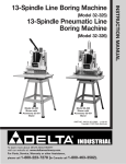
1
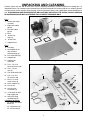
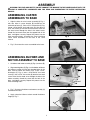
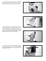
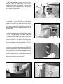
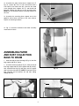
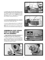
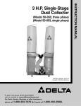
(Model 50-851)
PART NO. 902114 - 07-01-02
Copyright © 2002 Delta Machinery
To learn more about DELTA MACHINERY
visit our website at: www.deltamachinery.com.
For Parts, Service, Warranty or other Assistance,
please call
1-800-223-7278 (In Canada call 1-800-463-3582).
INSTRUCTION MANUAL
2 H.P. Single-Stage
Dust Collector
GENERAL SAFETY RULES
Woodworking can be dangerous if safe and proper operating procedures are not followed. As with all machinery, there
are certain hazards involved with the operation of the product. Using the machine with respect and caution will
considerably lessen the possibility of personal injury. However, if normal safety precautions are overlooked or ignored,
personal injury to the operator may result. Safety equipment such as guards, push sticks, hold-downs, featherboards,
goggles, dust masks and hearing protection can reduce your potential for injury. But even the best guard won’t make
up for poor judgment, carelessness or inattention. Always use common sense and exercise caution in the workshop.
If a procedure feels dangerous, don’t try it. Figure out an alternative procedure that feels safer. REMEMBER: Your
personal safety is your responsibility.
This machine was designed for certain applications only. Delta Machinery strongly recommends that this machine not
be modified and/or used for any application other than that for which it was designed. If you have any questions relative
to a particular application, DO NOT use the machine until you have first contacted Delta to determine if it can or should
be performed on the product.
Technical Service Manager
Delta Machinery
4825 Highway 45 North
Jackson, TN 38305
(IN CANADA: 505 SOUTHGATE DRIVE, GUELPH, ONTARIO N1H 6M7)
WARNING: FAILURE TO FOLLOW THESE RULES MAY RESULT IN SERIOUS PERSONAL INJURY
1. FOR YOUR OWN SAFETY, READ INSTRUCTION
MANUAL BEFORE OPERATING THE TOOL. Learn the
tool’s application and limitations as well as the specific
hazards peculiar to it.
2. KEEP GUARDS IN PLACE and in working order.
3. ALWAYS WEAR EYE PROTECTION. Wear safety
glasses. Everyday eyeglasses only have impact resistant
lenses; they are not safety glasses. Also use face or dust
mask if cutting operation is dusty. These safety glasses
must conform to ANSI Z87.1 requirements. Note:
Approved glasses have Z87 printed or stamped on them.
4. REMOVE ADJUSTING KEYS AND WRENCHES. Form
habit of checking to see that keys and adjusting wrenches
are removed from tool before turning it “on”.
5. KEEP WORK AREA CLEAN. Cluttered areas and
benches invite accidents.
6. DON’T USE IN DANGEROUS ENVIRONMENT. Don’t
use power tools in damp or wet locations, or expose them
to rain. Keep work area well-lighted.
7. KEEP CHILDREN AND VISITORS AWAY. All children
and visitors should be kept a safe distance from work area.
8. MAKE WORKSHOP CHILDPROOF – with padlocks,
master switches, or by removing starter keys.
9. DON’T FORCE TOOL. It will do the job better and be
safer at the rate for which it was designed.
10. USE RIGHT TOOL. Don’t force tool or attachment to
do a job for which it was not designed.
11. WEAR PROPER APPAREL. No loose clothing, gloves,
neckties, rings, bracelets, or other jewelry to get caught in
moving parts. Nonslip footwear is recommended. Wear
protective hair covering to contain long hair.
12. SECURE WORK. Use clamps or a vise to hold work
when practical. It’s safer than using your hand and frees
both hands to operate tool.
13. DON’T OVERREACH. Keep proper footing and
balance at all times.
14. MAINTAIN TOOLS IN TOP CONDITION. Keep tools
sharp and clean for best and safest performance. Follow
instructions for lubricating and changing accessories.
15. DISCONNECT TOOLS before servicing and when
changing accessories such as blades, bits, cutters, etc.
16. USE RECOMMENDED ACCESSORIES. The use of
accessories and attachments not recommended by Delta
may cause hazards or risk of injury to persons.
17. REDUCE THE RISK OF UNINTENTIONAL STARTING.
Make sure switch is in “OFF” position before plugging in
power cord. In the event of a power failure, move switch
to the “OFF” position.
18. NEVER STAND ON TOOL. Serious injury could occur if
the tool is tipped or if the cutting tool is accidentally
contacted.
19. CHECK DAMAGED PARTS. Before further use of the
tool, a guard or other part that is damaged should be
carefully checked to ensure that it will operate properly and
perform its intended function – check for alignment of
moving parts, binding of moving parts, breakage of parts,
mounting, and any other conditions that may affect its
operation. A guard or other part that is damaged should be
properly repaired or replaced.
20. DIRECTION OF FEED. Feed work into a blade or
cutter against the direction of rotation of the blade or cutter
only.
21. NEVER LEAVE TOOL RUNNING UNATTENDED.
TURN POWER OFF. Don’t leave tool until it comes to a
complete stop.
22. STAY ALERT, WATCH WHAT YOU ARE DOING, AND
USE COMMON SENSE WHEN OPERATING A POWER
TOOL. DO NOT USE TOOL WHILE TIRED OR UNDER
THE INFLUENCE OF DRUGS, ALCOHOL, OR
MEDICATION. A moment of inattention while operating
power tools may result in serious personal injury.
23. MAKE SURE TOOL IS DISCONNECTED FROM
P O W E R S U P P LY w h i l e m o t o r i s b e i n g m o u n t e d ,
connected or reconnected.
24. THE DUST GENERATED by certain woods and wood
products can be injurious to your health. Always operate
machinery in well ventilated areas and provide for proper
dust removal. Use wood dust collection systems whenever
possible.
SAVE THESE INSTRUCTIONS.
Refer to them often and use them to instruct others.
2
ADDITIONAL SAFETY RULES FOR
DUST COLLECTORS
WARNING: FAILURE TO FOLLOW THESE RULES MAY RESULT IN SERIOUS PERSONAL INJURY.
1. DO NOT OPERATE THIS MACHINE until it is
assembled and installed according to the instructions.
14. DO NOT use the dust collector as a toy. DO NOT
use near or around children.
2. OBTAIN ADVICE FROM YOUR SUPERVISOR,
instructor, or another qualified person if you are not
familiar with the operation of this machine.
15. DO NOT insert fingers or foreign objects into the
dust intake port or discharge port. Keep hair, loose
clothing, fingers, and all body parts away from openings
and moving parts of the dust collector.
3. FOLLOW ALL WIRING CODES and recommended
electrical connections.
16. DO NOT use with any opening blocked; keep
openings free of dust, lint, hair, and anything that may
reduce air flow.
4. DO NOT leave the dust collector plugged into the
electrical outlet. Unplug dust collector from the outlet
when not in use and before servicing, changing bags,
unclogging and cleaning.
17. NEVER use the dust collector without the dust
collection bag in place and properly secured.
5. ALWAYS turn all controls “OFF” before unplugging
the dust collector.
18. ALWAYS use intake cover to cover dust port when
the dust collector is not in use or mounted to a
supporting surface for storage.
6. TO REDUCE THE RISK OF ELECTRICAL SHOCK,
do not use on wet surfaces. Do not expose to rain. Store
indoors.
19. PERIODICALLY INSPECT dust bag for any cuts,
rips or tears. NEVER operate the dust collector with a
damaged bag or vacuum hose.
7. DO NOT use the dust collector to pick up
flammable or combustible liquids, such as gasoline.
NEVER use the dust collector near any flammable or
combustible liquids.
20. USE EXTRA CARE when cleaning on stairs.
21. TURN THE MACHINE “OFF” AND DISCONNECT
THE MACHINE from the power source before installing
or removing accessories, before adjusting or changing
set-ups, or when making repairs.
8. USE the dust collector to pick up wood materials
only. DO NOT use the dust collector to pick up metal
shavings, metal dust, or metal parts.
22. TURN THE MACHINE “OFF”, disconnect the
machine from the power source, and clean the
table/work area before leaving the machine. LOCK THE
SWITCH IN THE “OFF” POSITION to prevent
unauthorized use.
9. NEVER use the dust collector to dissipate fumes
or smoke. NEVER pick up anything that is burning or
smoking, such as cigarettes, matches or hot ashes.
10. DO NOT pull the dust collector by the power cord.
NEVER allow the power cord to come in contact with
sharp edges, hot surfaces, oil or grease. Do not place
anything over the top of the power cord.
23. ADDITIONAL INFORMATION regarding the safe
and proper operation of this tool is available from the
Power Tool Institute, 1300 Summer Avenue, Cleveland,
OH 44115-2851. Information is also available from the
National Safety Council, 1121 Spring Lake Drive, Itasca,
IL 60143-3201. Please refer to the American National
Standards Institute ANSI 01.1 Safety Requirements for
Woodworking Machines and the U.S. Department of
Labor OSHA 1910.213 Regulations.
11. DO NOT unplug the dust collector by pulling on the
power cord. ALWAYS grasp the plug, not the cord.
12. DO NOT handle the plug or dust collector with wet
hands.
13. REPLACE a damaged cord immediately. DO NOT
use a damaged cord or plug. If the dust collector is not
operating properly, or has been damaged, left outdoors
or has been in contact with water, take it to an
Authorized Service Center for service.
SAVE THESE INSTRUCTIONS.
Refer to them often
and use them to instruct others.
3
UNPACKING AND CLEANING
Carefully unpack the tool and all loose items from the shipping container(s). Remove the protective coating from all
unpainted surfaces. This coating may be removed with a soft cloth moistened with kerosene (do not use acetone, gasoline
or lacquer thinner for this purpose). After cleaning, cover the unpainted surfaces with a good quality household floor paste
wax. ILLUSTRATIONS ARE REPRESENTATIVE ONLY AND MAY NOT DEPICT THE ACTUAL COLOR, LABELING
OR ACCESSORIES AND MAY BE INTENDED TO ILLUSTRATE TECHNIQUE ONLY
Fig. 2
1 - Blower and motor
assembly
2 - Eight-hole rubber
gasket
3 - Ten-hole rubber
gasket
4 - Base
5 - Intake Port
Caps (3)
6 - Intake Ports
7 - Support Drum
Fig. 3
8 - Filter bag
9 - Locking bands for
filter and dust
collection bags (2)
10 - Dust collection bag
11 - Support rod
12 - Support rod
extension
13 - 5/16 - 18 x 5/8
hex head screws (48)
14 - 5/16 - 18 hex
nuts (6)
15 - 5/16 lockwashers (48)
16 - 5/16 x 7/8 O.D.
flat washers (26)
17 - M4.2 x 12 sheet
metal screws (4)
18 - Drum supports (2)
19 - Dust chute
20 - Swivel caster
assemblies (4)
21 - “U” bracket for filter
bag support rod
22 - Lower Dust Bag
retaining Clips (4)
* Hardware not shown
* - 1/4-20x5/8" Hex Head
Screws (8)
* - 1/4" Lockwashers (8)
* - 1/4"-20 Hex Nuts (8)
1
6
7
2
3
5
4
Fig. 2
19
11
22
20
8
12
21
17
16
9
14
10
13
Fig. 3
4
15
18
ASSEMBLY
WARNING: FOR YOUR OWN SAFETY, DO NOT CONNECT THE MACHINE TO THE POWER SOURCE UNTIL THE
MACHINE IS COMPLETELY ASSEMBLED AND YOU READ AND UNDERSTAND THE ENTIRE INSTRUCTION
MANUAL.
ASSEMBLING CASTER
ASSEMBLIES TO BASE
B
1. Align the holes in swivel caster assembly (A) Fig. 4,
with four holes in caster bracket (B) located on the
underside of base (C). Place a 5/16" lockwasher (E) Fig.
4 onto a 5/16-18x5/8" hex head screw (D), then place a
5/16" flat washer (F) onto the hex head screw. Insert the
hex head screw through the hole in the wheel caster,
thread the hex head screw into the tapped hole in the
base, and tighten securely. Repeat this process for the
three remaining holes. Assemble the three remaining
swivel caster assemblies to the base in the same
manner.
C
F
A
E
D
Fig. 4
2. Fig. 5, illustrates the caster assembled to the base.
ASSEMBLING BLOWER AND
MOTOR ASSEMBLY TO BASE
Fig. 5
1. Set blower and motor assembly (A) Fig. 6, on base (B).
2. Align mounting holes (C) Fig. 6, at the bottom of blower
and motor assembly (A) with four threaded holes in the
base, three of which are shown at (D). Place a 5/16"
lockwasher (F) Fig. 6, onto a 5/16-18x5/8" hex head
screw (E), then a 5/16" flat washer (G) onto the hex head
screw. Insert the hex head screw through the hole in the
motor assembly, thread the screw into the hole in the
base, and tighten securely. Repeat this process for the
three remaining holes.
A
B
C
D
D
E
F
G
Fig. 6
3. Fig. 7, illustrates the blower and motor assembly (A)
fastened to the base.
H
4. Apply a bead of silicone sealant around the blower
flange (H) Fig. 7.
A
Fig. 7
5
5. Place ten-hole rubber gasket (J) Fig. 8, on blower
flange (H). Align holes in gasket with mounting holes in
blower flange and press gasket onto flange as shown.
J
H
Fig. 8
K
A
J
6. Align mounting holes in chute (K) Fig. 9, with holes
in gasket (J), which was assembled in STEP 5. Place a
5/16" lockwasher onto a 5/16-18x5/8" hex head screw,
insert screw through the chute and gasket, thread the
screw into the motor assembly, and tighten securely.
Repeat this process for the 9 remaining holes.
Fig. 9
K
A
Fig. 10
7. Apply a bead of silicone sealant around flange of
chute (K) Fig. 11. Align holes in eight-hole gasket (M)
Fig. 11, with mounting holes in chute (K) and press gasket
into place as shown.
M
K
Fig. 11
6
8. Align mounting holes in drum (N) Fig. 12, with
gasket (M), which was assembled in STEP 7. Place a
5/16" lockwasher onto a 5/16-18x5/8" hex head screw,
insert screw (P) Fig. 13 through chute (K), thread screw
into drum (N) and tighten securely. Repeat this process
for the seven remaining holes.
N
K
M
Fig. 12
9. Assemble “U” bracket (R) Fig. 14, to side of drum
(N). Place a 5/16" lockwasher then a 5/16" flat washer
onto the 5/16-18x5/8" hex head screw. Insert the hex
head screw through the hole (S) in the “U” bracket and
the hole in the drum, thread a 5/16-18 hex nut onto the
screw and tighten securely. Repeat this process for the
remaining hole.
10. Align two mounting holes in the top of drum support
arm (T) Fig. 15, with two pre-drilled holes in drum (N).
Place a 5/16" lockwasher then a 5/16" flat washer onto
a 5/16-18x5/8" hex head screw, insert the hex head
screw through the hole (V) in drum support and drum.
Thread a 5/16-18 hex nut onto the hex head screw.
Repeat this process for the remaining hole. NOTE: Do
not completely tighten mounting hardware at this time.
K
P
Fig. 13
11. Attach the lower dust bag retaining clip (A) Fig. 14A,
to the dust collector drum. Align the two holes (B) in the
retaining clip (A) Fig. 14A, with the two holes in the drum.
Insert a 1/4-20x5/8" hex head screw through the holes in
the retaining clip and the holes in the drum. Place a 1/4"
flat washer onto the screws, and thread 1/4-20 hex nut
on the screws and tighten securely. Repeat this process
for the three remaining sides of the drum.
S
R
N
Fig. 14
N
B
A
T
V
Fig. 14A
Fig. 15
7
N
12. Assemble the other end of drum support arm (T)
Fig. 16, to base (B). Place a 5/16" lockwasher onto a
5/16-18x5/8" hex head screw (W), insert the hex head
screw through drum support arm (T), and thread into
base (B). Repeat this process for the remaining hole.
NOTE: Do not completely tighten mounting hardware at
this time.
T
B
13. Assemble the remaining drum support arm to the
opposite side of drum and base in the same manner.
Tighten all mounting hardware.
W
Fig. 16
14. Fig. 17, illustrates the blower and motor assembly
mounted to the base.
ASSEMBLING FILTER
AND DUST COLLECTION
BAGS TO DRUM
1. Hook the loop on top of filter bag (A) Fig. 18, into filter
bag support rod (B) as shown.
2. Assemble extension rod (C) Fig. 19, onto the end of
filter bag support rod (B). Raise support rods (B) and (C),
with attached filter bag (A) and place end of support
rods into holes of bracket (D). NOTE: Flared end of filter
bag extension rod will prevent the rod from sliding
through bracket.
Fig. 17
B
A
B
A
C
D
Fig. 18
Fig. 19
8
A
F
3. Position open end of filter bag (A) Fig. 20, over
upper lip of support drum (E). Insert locking band (F) Fig.
20, through the loops of filter bag (A) and fasten with
clamp (G) as shown in Fig. 21. NOTE: Make certain
locking band (F) Fig. 20, is positioned in the channel of
drum (E) before fastening clamp (G) Fig. 21.
F
G
E
Fig. 20
G
4. Pull up on each retaining clip (A) Fig. 22, and insert
the dust collection bag (B) underneath each retaining clip
to hold the dust collection bag in place.
5. Place the locking clamp (C) Fig. 22 around dust
collection bag and dust collector drum and lock in place.
NOTE: Make certain locking clamp is positioned in the
channel of the dust collector drum before locking clamp.
Fig. 21
ASSEMBLING DUST INTAKE
PORT TO BLOWER AND
MOTOR ASSEMBLY
C
A
1. MAKE CERTAIN THE DUST COLLECTOR IS
DISCONNECTED FROM THE POWER SOURCE.
2. Align the four holes in the dust intake port (A) Fig.
23, with the mounting holes in the lip of flange (B) of
blower assembly, and fasten with four sheet metal
screws (C). Fig. 24, illustrates the dust intake ports (A)
assembled to the blower assembly.
B
Fig. 22
A
B
A
C
Fig. 23
Fig. 24
9
3. Three dust intake port caps (D) Fig. 25, are supplied
with the dust collector. NOTE: These caps should be
inserted into the intake ports as shown, when they are
not in use.
WARNING: DO NOT INSERT FINGERS
OR ANY FOREIGN OBJECT INTO THE DUST INTAKE
PORTS WHEN UNIT IS OPERATING.
D
Fig. 25
CONNECTING MACHINE TO POWER SOURCE
ELECTRICAL CONNECTIONS
A separate electrical circuit should be used for your
tools. This circuit should not be less than #12 wire and
should be protected with a 20 amp time lag fuse. Use
proper extension cords. Make sure your extension cord
is in good condition and is a 3-wire extension cord
which has a 3-prong grounding type plug and a 3-hole
receptacle which will accept the tool’s plug. When using
an extension cord, be sure to use one heavy enough to
carry the current of the tool. An undersized cord will
cause a drop in line voltage, resulting in loss of power
and overheating. Fig. 25A, shows the correct gauge to
use depending on the cord length. If in doubt, use the
next heavier gauge. The smaller the gauge number, the
heavier the cord. Have a certified electrician repair or
replace damaged or worn cord immediately. Before
connecting the motor to the power line, make certain the
switch is in the “OFF” position and be sure that the
electric current is of the same characteristics as
stamped on the motor nameplate. All line connections
should make good contact. Running on low voltage will
damage the motor.
MINIMUM GAUGE EXTENSION CORD
RECOMMENDED SIZES FOR USE WITH STATIONARY ELECTRIC TOOLS
Ampere
Rating
Volts
Total Length
of Cord in Feet
0-6
0-6
0-6
0-6
240
240
240
240
up to 50
50-100
100-200
200-300
18 AWG
16 AWG
16 AWG
14 AWG
6-10
6-10
6-10
6-10
240
240
240
240
up to 50
50-100
100-200
200-300
18 AWG
16 AWG
14 AWG
12 AWG
10-12
10-12
10-12
10-12
240
240
240
240
up to 50
50-100
100-200
200-300
16 AWG
16 AWG
14 AWG
12 AWG
12-16
12-16
12-16
240
240
240
up to 50
50-100
14 AWG
12 AWG
GREATER THAN 100 FEET NOT RECOMMENDED
Fig. 25A
SINGLE PHASE
INSTALLATION
GROUNDED OUTLET BOX
The motor rating of the Model 50-851 Dust Collector is
2 HP, 230 Volt, Single Phase. Before connecting your
dust collector to an electrical power system, be sure the
electrical system agrees with the motor rating of the
tool.
The power cord is equipped with a plug that has two flat,
current-carrying prongs in tandem and one round or “U”
shaped, longer ground prong. This is used only with the
proper mating 3-conductor grounding type receptacle
as shown in Fig. 26.
When the 230 Volt three-prong plug on your machine is
plugged into a grounded 3-conductor receptacle, the long
ground prong on the plug contacts first so the machine
is properly grounded before electricity reaches it.
WARNING: MAKE CERTAIN THE RECEPTACLE IN
QUESTION IS PROPERLY GROUNDED. IF YOU ARE
NOT SURE, HAVE A QUALIFIED ELECTRICIAN CHECK
THE RECEPTACLE.
CURRENT CARRYING
PRONGS
GROUND PRONG
Fig. 26
10
Gauge of
Extension Cord
OPERATING CONTROLS
ON/OFF SWITCH
The “on/off” switch is located on the side of the motor.
To turn the dust collector “ON”, push the start button
(A) Fig. 27. To turn the dust collector “OFF”, push stop
button (B).
A
LOCKING SWITCH
IN THE “OFF” POSITION
B
IMPORTANT: When the machine is not in use, the switch
(A) Fig.18 should be locked in the OFF position using a
padlock with a 3/16" diameter shackle to prevent
unauthorized use.
Fig. 27
MAINTENANCE
WARNING: Before any maintenance or service is performed, be sure that the unit is disconnected from the power
source to prevent accidental starting.
MOTOR MAINTENANCE
Removing dust and dirt: Blow off motor with low pressure air to remove dust or dirt. Air pressure above 50 P.S.I. should
not be used, as high pressure may damage insulation and blow dirt under loosened tape. The operator performing this
cleaning function should always wear appropriate eye protective goggles. Built-up dust can cause excessive insulation
temperatures, thereby affecting motor life.
ACCESSORIES
A complete line of accessories is available from your Delta Supplier, Porter-Cable · Delta Factory Service Centers, and
Delta Authorized Service Stations. Please visit our Web Site www.deltamachinery.com for a catalog or for the
name of your nearest supplier.
WARNING: Since accessories, other than those offered by Delta, have not been tested
with this product, use of such accessories could be hazardous. For safest operation, only
Delta recommended accessories should be used with this product.
PARTS, SERVICE OR WARRANTY ASSISTANCE
All Delta Machines and accessories are manufactured to high quality standards and are serviced by a network of PorterCable · Delta Factory Service Centers and Delta Authorized Service Stations. To obtain additional information regarding
your Delta quality product or to obtain parts, service, warranty assistance, or the location of the nearest service outlet,
please call 1-800-223-7278 (In Canada call 1-800-463-3582).
Two Year Limited Warranty
Delta will repair or replace, at its expense and at its option, any Delta machine, machine part, or machine accessory which
in normal use has proven to be defective in workmanship or material, provided that the customer returns the product
prepaid to a Delta factory service center or authorized service station with proof of purchase of the product within two
years and provides Delta with reasonable opportunity to verify the alleged defect by inspection. Delta may require that
electric motors be returned prepaid to a motor manufacturer’s authorized station for inspection and repair or replacement.
Delta will not be responsible for any asserted defect which has resulted from normal wear, misuse, abuse or repair or
alteration made or specifically authorized by anyone other than an authorized Delta service facility or representative. Under
no circumstances will Delta be liable for incidental or consequential damages resulting from defective products. This
warranty is Delta’s sole warranty and sets forth the customer’s exclusive remedy, with respect to defective products; all
other warranties, express or implied, whether of merchantability, fitness for purpose, or otherwise, are expressly
disclaimed by Delta.
Printed in U.S.A.
11
PORTER-CABLE • DELTA SERVICE CENTERS
(CENTROS DE SERVICIO DE PORTER-CABLE • DELTA)
Parts and Repair Service for Porter-Cable • Delta Machinery are Available at These Locations
(Obtenga Refaccion de Partes o Servicio para su Herramienta en los Siguientes Centros de Porter-Cable • Delta)
ARIZONA
Tempe 85282 (Phoenix)
2400 West Southern Avenue
Suite 105
Phone: (602) 437-1200
Fax: (602) 437-2200
CALIFORNIA
Ontario 91761 (Los Angeles)
3949A East Guasti Road
Phone: (909) 390-5555
Fax: (909) 390-5554
San Leandro 94577 (Oakland)
3039 Teagarden Street
Phone: (510) 357-9762
Fax: (510) 357-7939
COLORADO
Arvada 80003 (Denver)
8175 Sheridan Blvd., Unit S
Phone: (303) 487-1809
Fax: (303) 487-1868
FLORIDA
Davie 33314 (Miami)
4343 South State Rd. 7 (441)
Unit #107
Phone: (954) 321-6635
Fax: (954) 321-6638
Tampa 33609
4538 W. Kennedy Boulevard
Phone: (813) 877-9585
Fax: (813) 289-7948
GEORGIA
Forest Park 30297 (Atlanta)
5442 Frontage Road,
Suite 112
Phone: (404) 608-0006
Fax: (404) 608-1123
ILLINOIS
Addison 60101 (Chicago)
400 South Rohlwing Rd.
Phone: (630) 424-8805
Fax: (630) 424-8895
Woodridge 60517 (Chicago)
2033 West 75th Street
Phone: (630) 910-9200
Fax: (630) 910-0360
MARYLAND
Elkridge 21075 (Baltimore)
7397-102 Washington Blvd.
Phone: (410) 799-9394
Fax: (410) 799-9398
MASSACHUSETTS
Braintree 02185 (Boston)
719 Granite Street
Phone: (781) 848-9810
Fax: (781) 848-6759
Franklin 02038 (Boston)
Franklin Industrial Park
101E Constitution Blvd.
Phone: (508) 520-8802
Fax: (508) 528-8089
MICHIGAN
Madison Heights 48071 (Detroit)
30475 Stephenson Highway
Phone: (248) 597-5000
Fax: (248) 597-5004
MINNESOTA
Minneapolis 55429
5522 Lakeland Avenue North
Phone: (763) 561-9080
Fax: (763) 561-0653
Cleveland 44125
8001 Sweet Valley Drive
Unit #19
Phone: (216) 447-9030
Fax: (216) 447-3097
MISSOURI
North Kansas City 64116
1141 Swift Avenue
P.O. Box 12393
Phone: (816) 221-2070
Fax: (816) 221-2897
OREGON
Portland 97230
4916 NE 122 nd Ave.
Phone: (503) 252-0107
Fax: (503) 252-2123
St. Louis 63119
7574 Watson Road
Phone: (314) 968-8950
Fax: (314) 968-2790
PENNSYLVANIA
Willow Grove 19090
520 North York Road
Phone: (215) 658-1430
Fax: (215) 658-1433
NEW YORK
Flushing 11365-1595 (N.Y.C.)
175-25 Horace Harding Expwy.
Phone: (718) 225-2040
Fax: (718) 423-9619
NORTH CAROLINA
Charlotte 28270
9129 Monroe Road, Suite 115
Phone: (704) 841-1176
Fax: (704) 708-4625
OHIO
Columbus 43214
4560 Indianola Avenue
Phone: (614) 263-0929
Fax: (614) 263-1238
TEXAS
Carrollton 75006 (Dallas)
1300 Interstate 35 N, Suite 112
Phone: (972) 446-2996
Fax: (972) 446-8157
Houston 77055
West 10 Business Center
1008 Wirt Road, Suite 120
Phone: (713) 682-0334
Fax: (713) 682-4867
WASHINGTON
Auburn 98001(Seattle)
3320 West Valley HWY, North
Building D, Suite 111
Phone: (253) 333-8353
Fax: (253) 333-9613
Authorized Service Stations are located in many large cities. Telephone 800-438-2486 or 731-541-6042 for assistance locating one.
Parts and accessories for Porter-Cable·Delta products should be obtained by contacting any Porter-Cable·Delta Distributor, Authorized
Service Center, or Porter-Cable·Delta Factory Service Center. If you do not have access to any of these, call 800-223-7278 and you will
be directed to the nearest Porter-Cable·Delta Factory Service Center. Las Estaciones de Servicio Autorizadas están ubicadas en muchas
grandes ciudades. Llame al 800-438-2486 ó al 731-541-6042 para obtener asistencia a fin de localizar una. Las piezas y los accesorios
para los productos Porter-Cable·Delta deben obtenerse poniéndose en contacto con cualquier distribuidor Porter-Cable·Delta, Centro
de Servicio Autorizado o Centro de Servicio de Fábrica Porter-Cable·Delta. Si no tiene acceso a ninguna de estas opciones, llame al
800-223-7278 y le dirigirán al Centro de Servicio de Fábrica Porter-Cable·Delta más cercano.
CANADIAN PORTER-CABLE • DELTA SERVICE CENTERS
ALBERTA
Bay 6, 2520-23rd St. N.E.
Calgary, Alberta
T2E 8L2
Phone: (403) 735-6166
Fax: (403) 735-6144
BRITISH COLUMBIA
8520 Baxter Place
Burnaby, B.C.
V5A 4T8
Phone: (604) 420-0102
Fax: (604) 420-3522
MANITOBA
1699 Dublin Avenue
Winnipeg, Manitoba
R3H 0H2
Phone: (204) 633-9259
Fax: (204) 632-1976
ONTARIO
505 Southgate Drive
Guelph, Ontario
N1H 6M7
Phone: (519) 836-2840
Fax: (519) 767-4131
QUÉBEC
1515 ave.
St-Jean Baptiste,
Québec, Québec
G2E 5E2
Phone: (418) 877-7112
Fax: (418) 877-7123
1447, Begin
St-Laurent, (Montréal),
Québec
H4R 1V8
Phone: (514) 336-8772
Fax: (514) 336-3505
The following are trademarks of PORTER-CABLE·DELTA (Las siguientes son marcas registradas de PORTER-CABLE S.A.): Auto-Set®,
BAMMER®, B.O.S.S.®, Builder’s Saw®, Contractor’s Saw®, Contractor’s Saw II™, Delta®, DELTACRAFT®, DELTAGRAM™, Delta Series
2000™, DURATRONIC™, Emc²™, FLEX ®, Flying Chips™, FRAME SAW ®, Homecraft ®, INNOVATION THAT WORKS ®, Jet-Lock ®,
JETSTREAM®, ‘kickstand®, LASERLOC®, MICRO-SET®, Micro-Set®, Midi Lathe™, MORTEN™, NETWORK™, OMNIJIG®, POCKET
CUTTER®, PORTA-BAND®, PORTA-PLANE®, PORTER-CABLE®&(design), PORTER-CABLE®PROFESSIONAL POWER TOOLS, Posi-Matic®,
Q-3®&(design), QUICKSAND®&(design), QUICKSET™, QUICKSET II®, QUICKSET PLUS™, RIPTIDE™&(design), SAFE GUARD II®, SAFELOC®, Sanding Center®, SANDTRAP®&(design), SAW BOSS®, Sawbuck™, Sidekick®, SPEED-BLOC®, SPEEDMATIC®, SPEEDTRONIC®,
STAIR EASE®, The American Woodshop®&(design), The Lumber Company®&(design), THE PROFESSIONAL EDGE®, THE PROFESSIONAL
SELECT ®, THIN-LINE™, TIGER ®, TIGER CUB ®, TIGER SAW ®, TORQBUSTER ®, TORQ-BUSTER ®, TRU-MATCH™, TWIN-LITE ®,
UNIGUARD®, Unifence®, UNIFEEDER™, Unihead®, Uniplane™, Unirip®, Unisaw®, Univise®, Versa-Feeder®, VERSA-PLANE® , WHISPER
SERIES®, WOODWORKER’S CHOICE™.
Trademarks noted with ™ and ® are registered in the United States Patent and Trademark Office and may also be registered in other
countries. Las Marcas Registradas con el signo de ™ y ® son registradas por la Oficina de Registros y Patentes de los Estados Unidos y
también pueden estar registradas en otros países.
Printed in U.S.A.