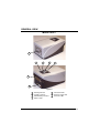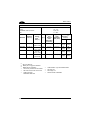
1
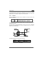
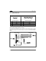
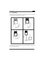
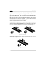
Matrix-1000™ Reference Manual Matrix-1000™ REFERENCE MANUAL DATALOGIC S.p.A. Via Candini 2 40012 - Lippo di Calderara di Reno Bologna - Italy Matrix-1000™ Reference Manual Ed.: 10/2004 ALL RIGHTS RESERVED Datalogic S.p.A. reserves the right to make modifications and improvements without prior notification. Datalogic shall not be liable for technical or editorial errors or omissions contained herein, nor for incidental or consequential damages resulting from the use of this material. Product names mentioned herein are for identification purposes only and may be trademarks and or registered trademarks of their respective companies. Datalogic S.p.A. 2000 - 2004 12/10/04 CONTENTS REFERENCES ............................................................................................. v Conventions .................................................................................................. v Reference Documentation ............................................................................ v Service, Support and Warranty ..................................................................... v SAFETY PRECAUTIONS............................................................................ vi Power Supply................................................................................................vi compliance label ...........................................................................................vi GENERAL VIEW ........................................................................................ vii GUIDE TO INSTALLATION ...................................................................... viii 1 1.1 1.2 1.3 1.4 1.5 GENERAL FEATURES ................................................................................ 1 Introduction ................................................................................................... 1 Description .................................................................................................... 2 Model description.......................................................................................... 4 Available Accessories ................................................................................... 4 Application Examples.................................................................................... 5 2 2.1 2.2 2.2.1 2.3 2.3.1 2.3.2 2.3.3 2.3.4 2.3.5 2.4 2.5 2.6 2.6.1 2.6.2 INSTALLATION............................................................................................ 7 Package Contents......................................................................................... 7 Mechanical Installation.................................................................................. 8 Mounting Matrix-1000™.............................................................................. 10 Electrical Connections................................................................................. 11 Power Supply.............................................................................................. 14 RS485 Half-Duplex Main Interface.............................................................. 15 Auxiliary RS232 Interface............................................................................ 17 Input............................................................................................................ 19 Outputs ....................................................................................................... 21 User Interface ............................................................................................. 22 Positioning .................................................................................................. 23 Typical Layouts ........................................................................................... 25 Point-to-Point .............................................................................................. 25 Multiplexer................................................................................................... 26 3 3.1 3.2 3.3 3.3.1 3.4 3.4.1 SOFTWARE CONFIGURATION ................................................................ 27 VisiSet™ System Requirements ................................................................. 27 Installing VisiSet™ ...................................................................................... 27 Startup ........................................................................................................ 28 VisiSet™ Options........................................................................................ 29 Configuration............................................................................................... 31 Edit Reader Parameters.............................................................................. 32 iii 3.4.2 3.5 3.6 Calibration................................................................................................... 35 Image Capture and Decoding ..................................................................... 39 Statistics...................................................................................................... 40 4 4.1 MAINTENANCE ......................................................................................... 41 Cleaning...................................................................................................... 41 5 5.1 TROUBLESHOOTING................................................................................ 42 General Guidelines ..................................................................................... 42 6 TECHNICAL FEATURES ........................................................................... 46 GLOSSARY................................................................................................ 49 INDEX ......................................................................................................... 51 iv REFERENCES CONVENTIONS This manual uses the following conventions: "User" refers to anyone using a Matrix-1000™ reader. "Reader" refers to the Matrix-1000™ reader. "You" refers to the System Administrator or Technical Support person using this manual to install, configure, operate, maintain or troubleshoot a Matrix-1000™ reader. REFERENCE DOCUMENTATION For further details refer to: the VisiSet™ Help On Line, Matrix Reading Methods, Matrix Host Mode Programming, Matrix SW Parameter Guide, provided as supplementary documentation on CD-ROM. SERVICE, SUPPORT AND WARRANTY Datalogic provides several services as well as technical support through its website. Log on to www.datalogic.com/services and click on the links indicated for further information including: · Datalogic Services - Warranty Extensions and Maintenance Agreements · Downloads - Software Downloads, Manuals and Catalogues · Contact Us - Listing of Datalogic Subsidiaries and Quality Partners · Authorised Repair Centres v SAFETY PRECAUTIONS For installation, use and maintenance it is not necessary to open the reader. POWER SUPPLY ATTENTION: READ THIS INFORMATION BEFORE INSTALLING THE PRODUCT - This product is intended to be installed by Qualified Personnel only. This product is intended to be connected to a UL Listed Computer which supplies power directly to the reader or a UL Listed Direct Plug-in Power Unit marked LPS or “Class 2”, rated 10 to 30 V, minimum 1 A. COMPLIANCE LABEL TO EN60825-1:2001 vi GENERAL VIEW Matrix-1000™ 1 4 6 5 7 3 2 Figure A 1 2 3 4 Reading Window Auxiliary Interface Main/Auxiliary Interface Main Tx LED 5 6 Good Read LED 7 Power On LED External Trigger LED vii GUIDE TO INSTALLATION The following can be used as a checklist to verify all of the steps necessary for complete installation of the Matrix-1000 compact 2D reader. 1) Read all information in the section "Safety Precautions" at the beginning of this manual. 2) Correctly mount the reader using the bracket provided (sub-pars. under 2.2). 3) Position the reader at the correct reading distance according to your model (par. 2.5). 4) Make electrical connections to your Matrix-1000™ reader by either: a) b) 5) Connecting the test cable to the Matrix-1000™ reader (par.2.4). Providing correct and complete system cabling according to the signals necessary for the layout of your application. • Layout: Point-to-point or Multidrop, etc. (sub-pars: 2.6); • Cabling: Power, Main RS485, Auxiliary RS232, External Trigger Input and Output (sub-pars. under 2.3). Configure the Matrix-1000™ reader by installing and running VisiSet™ from the CD-ROM provided onto the configuration PC (pars. 3.1, 3.2, 3.3). See the Rapid Guide to Configuration in the VisiSet™ Help On Line. The main steps are: a) Select the codes to be read b) Set-up the communication parameters c) Define data formatting parameters d) Fine tune your Matrix-1000™ reader using the VisiSet™ Calibration Tool (par. 3.4.2). Specific VisiSet™ parameter details are also available in the Help On Line. 6) Exit the configuration program and run your application. The installation is now complete. viii GENERAL FEATURES 1 1.1 1 GENERAL FEATURES INTRODUCTION Matrix-1000 is an area CCD reader for industrial application using 2D, 1D, stacked and postal codes. Matrix-1000 uses imaging technology and provides complete reading system functions by integrating: lighting system, image acquisition, image processing, decoding and communication into a single compact unit. This technology intrinsically provides omni-directional reading. Standard Application Program A Standard Application Program is factory-loaded onto Matrix-1000. This program controls code reading, data formatting, serial port, and many other operating and control parameters. It is completely user configurable from a Laptop or PC using the dedicated configuration software named VisiSet™ provided on CD-ROM with the reader. There are different programmable operating modes to suit various code reading system requirements. A Calibration Tool is provided to verify the exact positioning of the reader and to maximize its reading performance. Programmability If your requirements are not met by the Standard Application Program, Custom Application Programs can be requested at your local Datalogic distributor. 1 Matrix-1000™ 1 1.2 DESCRIPTION Some of the main features of this reader are given below: • Decoding of most popular linear and stacked barcodes, 2D code symbologies and postal codes • Omni-directional reading • Frame rate up to 30 frames/sec (1800 frames/min) • Moving code reading • Calibration Tool to verify exact code positioning in the Field of View and to maximize the reading performance • Parameter configuration via Windows-based VisiSet™ software • Different operating modes to suit various application requirements • User-defined database of acquisition recipes (parameter sets) • Verifier option with a user-defined match code database • Diagnostic software tools • 2 serial communication interfaces • General purpose optocoupled I/Os • Supply voltage ranges from 10 to 30 Vdc The reader is contained in a magnesium alloy housing; the mechanical dimensions are 121 x 73 x 57 mm and it weighs about 330 g. The protection class of the enclosure is IP64; therefore the reader is particularly suitable for industrial environments where protection against harsh external conditions is required. 2 GENERAL FEATURES 1 Electrical connection of Power, serial interfaces and I/O signals is provided through a 25-pin connector (see Figure A, 3). In addition there is a 9-pin Auxiliary interface connector for reader configuration (see Figure A, 2). The following indicators are located on the top of the reader: PWR red LED indicates that the reader is connected to the power supply (see Figure A, 7); TRIG yellow LED indicates external trigger activity (Figure A, 6); for details refer to par 2.3.4; READ red LED signals successful code decoding (Figure A, 5). It is also used to signal successful startup. At power on this LED turns on and after a few seconds turns off. If the startup is not successful, this LED remains on. COM green LED indicates data transmission on the main serial interface (Figure A, 4). 3 Matrix-1000™ 1 1.3 MODEL DESCRIPTION The Matrix-1000 reader is available in different versions according to the Optical Characteristics. MATRIX - 10X1 Optics 2 = High Density (HD) 3 = Standard Density (SD) 4 = Low Density (LD) 5 = Medium Range (MR) 1.4 AVAILABLE ACCESSORIES Order no. 93A051190 93A051200 93A051210 93ACC1510 93A301000 93A301030 93A301010 93A301040 93ACC1718 93ACC1719 93ACC1720 93A201090 4 Accessory CAB-6001 CAB-6002 CAB-6005 C-BOX 100 C-BOX 300 C-BOX 310 C-BOX 400 C-BOX 410 PG6002 PG6001 PG6000 GFC-MATRIX-1000 Description cable to C-BOX100 1 m cable to C-BOX100 2 m cable to C-BOX100 5 m passive connection box Connection box PROFIBUS Connection box PROFIBUS with display Connection box DeviceNet Connection box DeviceNet with display AC/DC power supply unit (US) AC/DC power supply unit (UK) AC/DC power supply unit (EU) 90° deflection mirror GENERAL FEATURES 1.5 1 APPLICATION EXAMPLES The Matrix-1000™ wide choice of fields of view and high performance of decoding libraries allow the reading of many small codes (see 96 vial application in Figure 1) as well as deformed and / or overprinted codes also when they are damaged or printed on high reflective surfaces (see Figures 2, 3, 4). Figure 1 - 96-vial Rack with DataMatrix Codes to Track Each Vial Throughout its Biomedical Analysis Process Figure 2 - Unidose Flow-Pack with PDF417 Code Figure 3 - Overprinted Barcode Readable by Matrix-1000™ also Through the Envelope Window Film 5 1 Matrix-1000™ Figure 4 - Barcode Printed on Curved Surface Readable by Matrix-1000™ in spite of Image Optical Distortion The Matrix-1000™ is particularly suitable for applications requiring an array of readers to cover a very large reading area (see Figure 5). Figure 5 - Ten readers connected to a Datalogic MX4000 through a multidrop network. 6 INSTALLATION 2 2.1 2 INSTALLATION PACKAGE CONTENTS Verify that the Matrix-1000 reader and all the parts supplied with the equipment are present and intact when opening the packaging; the list of parts includes: Matrix-1000 reader Quick Reference Guide Test chart Matrix family CD-ROM Auxiliary port connector cover Mounting kit • Mounting screws and washers (4 ea.) • Mounting bracket Figure 6 - Package Contents 7 Matrix-1000™ 2 2.2 MECHANICAL INSTALLATION Matrix-1000 can be installed to operate in different positions. The eight screw holes (M4 x 5) on the body of the reader are for mechanical fixture (Figure 7). The diagram below gives the overall dimensions of the reader and may be used for its installation. Refer to paragraph 2.5 for correct positioning. 57 [2.24] = mm [inch] M4 x 5 n°4 57 [2.24] 121 [4.76] 28.1 [1.11] = 73 [2.87] 57 [2.24] 18.1 [0.71] 57 [2.24] 4 [0.16] M4 x 5 n°4 Figure 7 - Overall Dimensions 8 INSTALLATION 2 73 [2.87] 95 [3.74] .2 Ø4 7] .1 [Ø0 37 [1.46] 15 [0.59] 47.5 [1.87] 2 [0.08] 47.5 [1.87] 95 [3.74] 2 8. ] Ø .32 0 [Ø 4.2 [0.17] mm [inch] Figure 8 - Mounting Bracket Dimensions 9 Matrix-1000™ 2 2.2.1 Mounting Matrix-1000™ Using the Matrix-1000™ mounting bracket you can obtain vertical shift and rotation of the reader as shown in the diagram below: Figure 9 - Positioning with Mounting Brackets 10 INSTALLATION 2.3 2 ELECTRICAL CONNECTIONS The Matrix-1000 reader is equipped with a 25-pin male D-Sub connector for connection to the power supply and input/output signals. The details of the connector pins are indicated in the following table: 1 13 14 25 Figure 10 - 25-pin male D-Sub Connector 25-pin male D-sub connector pinout Pin 1 Name SHIELD 2 RTX485+ 4 RTX485- 7 3,5 20 SGND NC RXAUX 21 TXAUX 8, 22 11, 12 16 17 18 19 6, 10 14, 15, 24 9,13 23, 25 NC NC OUT 3 + OUT 3 EXT_TRIG A EXT_TRIG B NC NC VS GND Function Cable shield internally connected by capacitor to the chassis Rx or Tx data of RS485 Half Duplex Main Interface positive pin Rx or Tx data of RS485 Half Duplex Main Interface negative pin Reference GND of RS485 Half Duplex Main Interface Received data of RS232 Auxiliary Interface (referred to GND) Transmitted data of RS232 Auxiliary Interface (referred to GND) Not connected Not connected Configurable digital output 3 - positive pin Configurable digital output 3 - negative pin External trigger (polarity insensitive) External trigger (polarity insensitive) Not connected Not connected Supply voltage - positive pin Supply voltage - negative pin 11 Matrix-1000™ 2 There is also a separate 9-pin female D-sub connector for the Auxiliary port connection with the following pinout: 1 5 9 6 Figure 11 - 9-pin female D-Sub Connector 9-pin female D-sub connector pinout Pin Name 2 3 5 1,4,6,7,8,9 TXAUX RXAUX GND N.C. CAUTION Function Transmitted data of RS232 Auxiliary Interface Received data of RS232 Auxiliary Interface Reference GND of RS232 Auxiliary Interface Not connected Do not connect GND and SGND to different (external) ground references. GND and SGND are internally connected through filtering circuitry which can be permanently damaged if subjected to voltage drops over 0.8 Vdc. In order to meet EMC requirements: • connect the reader chassis to the plant earth ground by means of a flat copper braid shorter than 100 mm; • connect the main interface cable shield to pin 1 of the 25-pin connector; • use two clip-on ferrite sleeves (type Stewart 28A2029-0A0 or equivalent) on the main interface cable near the reader 25-pin connector. 12 INSTALLATION 2 C-BOX pinout for Matrix-1000™ The table below gives the pinout of the C-BOX 100 terminal block connectors. Use this pinout when the Matrix-1000™ reader is connected by means of the C-BOX 100: C-BOX 100 Terminal Block Connectors Power 1, 3, 5 2, 4, 6 7, 8 20, 40 27 28 29, 30 31, 33 32, 34 36 21, 22 23, 24 25 26 35 37 38, 39 11, 15 12, 16 17 18 10, 14, 19 9, 13 VS GND EARTH GROUND Reserved Inputs EXT TRIG A (polarity insensitive) EXT TRIG B (polarity insensitive) NC NC NC NC Outputs NC NC OUT 3+ OUT 3Auxiliary Interface TX AUX RX AUX GND Main Interface RS485 Half-Duplex RTX485+ RTX485NC NC SGND RS485 Cable Shield 13 Matrix-1000™ 2 2.3.1 Power Supply Power is supplied to the reader through the pins provided on the 25-pin connector (see Figure 12): USER INTERFACE MATRIX VS GND SHIELD 9/13 23/25 V+ (10 - 30 Vdc) V- (Ground) 1 Figure 12 - Power Supply Connection The allowed supply voltage range is 10 to 30 Vdc. 14 CHASSIS INSTALLATION 2.3.2 2 RS485 Half-Duplex Main Interface The RS485 half-duplex (3 wires + shield) interface is available for polled communication protocols. It can be used for multidrop connections with a Datalogic Multiplexer, (see Figure 13 and par. 2.6.2). The following pins of the 25-pin connector are used for RS485 half-duplex communication: Pin Name Function 2 RTX485+ Transmitted/received data (+) 4 RTX485- Transmitted/received data (-) 7 SGND* Main reference ground *SGND is internally connected to the GND through a filtering circuit. MATRIX MULITPLEXER 2 RTX485+ RTX485SGND 4 7 RTX485+ RTX485RS485REF 1 SHIELD Earth Ground Figure 13 - RS485 Half-duplex Connections 15 Matrix-1000™ 2 The figure below shows a multidrop configuration with Matrix-1000™ readers connected to a Multiplexer. max. 2 m. 120 Ohm 1 MATRIX 2 #x (up to 31) 4 7 1 MATRIX 2 #1 4 7 max. 1200 m. 1 MATRIX 2 #0 4 7 three wires + shield RTX485+ MULTIPLEXER RTX485RS485REF SHIELD Earth Ground 120 Ohm Figure 14 - Matrix-1000™ Multidrop Connection to a Mutiplexer 16 INSTALLATION 2.3.3 2 Auxiliary RS232 Interface The RS232 auxiliary interface is available for Point-to-Point connections. When it is connected to the host computer it allows both transmission of code data and reader configuration by VisiSet™. Its communication parameters (baud rate, data bits, etc.) can be defined by the user. For more details refer to the "Communication" folder in the VisiSet™ Help On Line. The RS232 interface is available on both Matrix-1000™ D-sub connectors with the following pinouts: 9-Pin 2 3 25-Pin 21 20 5 23 Name TXAUX RXAUX Function Transmitted data Received data GND Ground MATRIX USER INTERFACE 20 RXAUX TXAUX GND 21 23 TXD RXD Ground 1 Earth Ground SHIELD Figure 15 - RS232 Interface Connections Using 25-pin Connector MATRIX USER INTERFACE 3 RXAUX TXAUX GND 2 5 TXD RXD Ground Figure 16 - RS232 Interface Connections Using 9-pin Connector 17 2 Matrix-1000™ When the auxiliary interface is permanently connected as part of the system cabling, it is recommended to use the 25-pin connector and connect the cable shield as shown in Figure 15. Avoid simultaneous connection to 25-pin and 9-pin signals of the auxiliary RS232 interface. CAUTION 18 INSTALLATION 2.3.4 2 Input An opto-coupled and polarity insensitive input is available on the 25-pin connector. The pinout is the following: Pin Name Function 18 EXT_TRIG A External trigger (polarity insensitive) 19 EXT_TRIG B External trigger (polarity insensitive) When current flows through the EXT_TRIG input, the yellow LED (Figure A, 6) is on. The External Trigger can be used in One Shot Mode or in Phase Mode. Its main functions are: • acquisition trigger in One Shot Mode • phase-ON/phase-OFF command in Phase Mode • match code storage command. This input can be driven by either a PNP or NPN type command. The connections are indicated in the following diagrams: Polarity insensitive input assure full functionality even if pins A and B are exchanged. NOTE Vext MATRIX 30 Vdc Max. USER INTERFACE + V OUT A VCC ~ I in - + ~ B GND Figure 17 - Input PNP Command Using External Power 19 Matrix-1000™ 2 MATRIX USER INTERFACE VS 9 + V OUT A VCC ~ - + ~ B GND GND 25 Figure 18 - Input PNP Command Using Matrix-1000 Power MATRIX Vext USER INTERFACE 30 Vdc Max. VS VCC A + V ~ - + ~ OUT B GND Figure 19 - Input NPN Command Using External Power MATRIX USER INTERFACE VS 9 A VCC + V ~ - + ~ B GND OUT GND 25 Figure 20 - Input NPN Command Using Matrix-1000 Power The electrical features of the input are: INPUT Open Closed 20 | V AB | Min. 0V 4.5 V | V AB | Max. 2V 30 V I IN Max. 0 mA 10 mA INSTALLATION 2 An anti-disturbance filter (debouncing) is implemented on the input, and is software programmable. The input active state can be defined by the user as well. Refer to the digital I/O folder in the VisiSet™ Help On Line for further details. 2.3.5 Outputs One optocoupled general purpose output is available on the 25-pin connector. The pinout is the following: Pin Name Function 16 17 OUT3+ OUT3- Configurable digital output 3 - positive pin Configurable digital output 3 - negative pin It is typically used to signal the data collection result. It can also be used to control an external lighting system The idle state, the activation/deactivation events and the other configuration parameters can be defined by the user. Refer to the Digital I/O folder in the VisiSet™ Help On Line for further details. MATRIX USER INTERFACE Vext 30 Vdc max + V Out I Load - Figure 21 - Open Collector Output Connection The electrical features of the output are the following: OUTPUT Open Closed ILoad 0 mA 10 mA VOut 30 Vdc Max 1.8 Vdc Max PD = VOut × IoLoad = 170 mW Max. 21 Matrix-1000™ 2 2.4 USER INTERFACE RS232 PC-side connections 1 5 1 6 14 9 25 25-pin male connector 9-pin male connector Pin 2 3 5 7 8 13 Name RX TX GND RTS CTS Pin 3 2 7 4 5 Name RX TX GND RTS CTS How To Build A Simple Interface Test Cable: The following wiring diagrams show a simple test cable including power, external (push-button) trigger and PC RS232 COM port connections. Test Cable for Matrix1000™ 25-pin D-sub female 9-pin D-sub female 21 TXAUX 2 RX 20 RXAUX 3 TX 5 GND 23 GND 13 VS 25 GND MATRIX1000™ 9 VS 18 EXT TRIG+ 19 EXT TRIG- Power Supply VS (10 – 30 VDC) Power GND Trigger Figure 22- Test Cable 22 PC INSTALLATION 2.5 2 POSITIONING Position the reader so that the distance from the reading window to the code surface is that indicated in the figure below for your model. SD HD FOV 25 x 19 mm (0.19 x 0.75 in) focus distance 115 mm (4.52 in) focus distance 155 mm (6.10 in) FOV 34 x 26 mm (1.34 x 1.02 in) code surface code surface MR LD FOV 54 x 40 mm (2.13 x 1.57 in) FOV 95 x 70 mm (3.74 x 2.75 in) focus distance 210 mm (8.26 in) focus distance 110 mm (4.33 in) code surface code surface Figure 23 - Positioning Special models with different FOV and focus distance are available on request. Refer to your local Datalogic distributor. 23 Matrix-1000™ 2 Matrix-1000 is able to decode code labels at a variety of angles, however significant angular distortion may degrade reading performance. When mounting Matrix-1000, take into consideration these ideal label position angles: Pitch 10° to 20° and Tilt 0°. Note: Since Matrix-1000 is omni-directional on the code plane, e Pitch and Skew angles have the same significance with respect to the code plane. To simplify therefore, we will use Pitch to describe both these angles. Follow the suggestions below for the best orientation: The Pitch angles are represented by the values P and S in Figure 24. Position the reader in order to avoid the direct reflection of the light emitted by the Matrix-1000 reader; it is advised to assure at least 10° for one of these angles. In some cases, such as low contrast or low illumination, it can be useful to use a Pitch angle = 0°. Figure 24 - Pitch angles The Tilt angle is represented by the value T in Figure 25. Matrix-1000 can read labels with any tilt angle. Figure 25 - Tilt angle 24 INSTALLATION 2.6 2 TYPICAL LAYOUTS The following typical layouts refer to system hardware configurations. However, they also require the correct setup of the software configuration parameters. Dotted lines in the figures refer to optional hardware configurations within the particular layout. 2.6.1 Point-to-Point In this layout the data is transmitted to the Host on the Matrix-1000 aux serial interface. Parameter configuration can always be accomplished using the Matrix-1000 auxiliary interface. When either Phase Mode or One Shot operating mode are used, the reader can be activated by an external event (for example a pulse from a photoelectric sensor) when the object enters its reading zone. CAB-600X C-BOX 100 Matrix-1000™ Local Host P.S. PG6000 Auxiliary Interface (Local Echo) External Trigger Figure 26 - Point-to-Point Layout 25 Matrix-1000™ 2 2.6.2 Multiplexer Each reader is connected to a MX4000 through a multidrop network. Before proceeding with the connection it is necessary to select the MUX32 communication protocol and the multidrop address for each reader. 1 0 31 Matrix-1000™ Power MX4000 C-BOX 100 C-BOX 100 C-BOX 100 Multidrop Network - Main Interface Auxiliary Interface (Local Echo) External Trigger Host Figure 27 - Multiplexer Layout The Aux serial interface of each reader can be used for configuration purposes, using VisiSet™, or in Local Echo communication mode to control the single device operation. 26 SOFTWARE CONFIGURATION 3 3 SOFTWARE CONFIGURATION Software configuration of your Matrix-1000 reader can be accomplished by VisiSet™ through the Matrix-1000 auxiliary serial interface. 3.1 VISISET™ SYSTEM REQUIREMENTS To install and run VisiSet™ you should have a Laptop or PC that meets or exceeds the following: • Pentium processor • Win 95/98/2000, NT 4.0 or XP • 32 MB Ram • 5 MB free HD space • one free RS232 serial port with 115 Kbaud • SVGA board (800x600) or better using more than 256 colors 3.2 INSTALLING VISISET™ To install VisiSet™, proceed as follows: 1. Turn on the Laptop or PC that will be used for configuration (connected to the Matrix-1000 auxiliary port). 2. After Windows finishes booting, insert the CD-ROM provided. 3. Launch VisiSet™ installation by clicking Install VisiSet™. 4. Follow the instructions in the installation procedure. 27 Matrix-1000™ 3 3.3 STARTUP After completing the mechanical and electrical connections to Matrix-1000, you can begin software configuration as follows: 1. Power on the Matrix-1000 reader. Wait for the reader startup. The system bootstrap requires a few seconds to be completed. The reader automatically enters Run Mode. 2. Run the VisiSet™ program. 3. Press Connect on the VisiSet™ menu bar. The PC will automatically connect to the Matrix-1000 reader. Upon connection, Matrix-1000 exits Run Mode and displays the Main Menu on VisiSet™ with all the commands necessary to monitor your reader's performance. You can select these commands using the mouse or by pressing the key corresponding to the letter shown on the button. See Figure 28. Menu Bar Commands Window Terminal Window Status Bar Figure 28 - Main Window 28 SOFTWARE CONFIGURATION 3.3.1 3 VisiSet™ Options The Options item from the VisiSet™ menu (see Figure 28) presents a window allowing you to configure: − the logging function (Log) − VisiSet™ window properties (Environment) − VisiSet™ serial communication (Communication) Figure 29 - Options - Log 29 Matrix-1000™ 3 Figure 30 - Options - Environment Figure 31 - Options - Communication 30 SOFTWARE CONFIGURATION 3.4 3 CONFIGURATION Once connected to Matrix-1000 as described in par. 3.3, you can modify the configuration parameters as follows: 1. Press the Calibration Tool button from the Main Menu. Matrix-1000™ will download its permanent memory configuration parameters with the default values (if it is the first time) to VisiSet™. The Calibration Tool window will be displayed together with the Parameter Setup window working in Interactive Mode (see par. 3.4.1 and par. 3.4.2). 2. Edit the Matrix-1000 configuration parameters according to your application requirements. 3. Use the Calibration Tool to fine tune the reading performance. See par. 3.4.2. 4. Close the Calibration Tool window and disable the Interactive Mode by pressing the interactive button. 5. Save the new configuration to the reader permanent memory by pressing the Send button. 6. Close the Parameter Setup window and press Disconnect on the VisiSet™ menu bar (see Figure 28) or launch Run Mode from the VisiSet™ Main menu. Disconnect exits closing communication between Matrix-1000 and VisiSet™, and causes Matrix-1000 to enter Run Mode. The disconnected reader serial port is now available for other purpose. Run command does not close communication between Matrix-1000 and VisiSet™, and causes Matrix-1000 to enter Run Mode. In this case the reader output messages are displayed on the VisiSet™ terminal and the statistics are displayed in the Statistics window (Statistics enabled). 31 Matrix-1000™ 3 3.4.1 Edit Reader Parameters The Parameter Setup window displays the configuration parameters grouped in a series of folders. Each parameter can be modified by selecting a different item from the prescribed list in the box, or by typing new values directly into the parameter box. By right clicking the mouse when positioned over the name of a specific Parameter or Group, a pop-up menu appears allowing you to directly manage that particular parameter or group. You can View the selected value for each parameter. You can Restore the default value of each parameter or of all the parameters of a group. Get properties gives information about the parameter in the form of a pop-up hint that describes the default value and the range/list of valid values. The Short help gives information about the parameter in the form of a pop-up hint. Parameter Group Single group/parameter management (right click) Parameter Figure 32 - Editing Parameters 32 SOFTWARE CONFIGURATION 3 Parameters to verify/modify: Operating mode Sets the parameters which customize the reader operating mode starting from three main modes: One-shot: acquires a single image based on the selected value for the Acquisition Trigger and Delayed Triggers. Continuous: continuously acquires images with a rate up to 30 frames per second depending on the decoding time. Phase Mode: acquires images during the reading phase depending on the selected value for the Acquisition Trigger and Delayed Triggers. The Phase-ON and Phase-OFF events mark respectively the beginning and end of the reading phase. Calibration Calibrates the acquisition parameters to maximize the reading performance (see par. 3.4.2) Communication Configures the parameters relative to each serial port regarding the transmission, message formatting and string receiving. Any change to the VisiSet™ communication port parameters (baud rate, data bits, etc.) is effective as soon as the reader is disconnected from VisiSet™. Decoding Sets the decoding parameters shared by several code symbologies. 1D & Codes 2D, Postal Sets the characteristics of the code symbologies to be read. Data Collection Defines the code-collection parameters and the output message format. Digital I/O Configures the reader input/output parameters. Verifier Sets the verifier mode to compare the read code to a userdefined database. Miscellaneous Sets the reader name and the saved image format. 33 3 Matrix-1000™ When all the configuration parameters are set correctly, save them to the Matrix1000 reader by pressing the Send button. See Figure 32. For successive configuration of other readers or for backup/archive copies, it is possible to save the configuration onto your PC by selecting the Save pars to file option from the File menu. Load pars from file (available in the File menu) allows you to configure a reader from a previously saved configuration file. 34 SOFTWARE CONFIGURATION 3.4.2 3 Calibration VisiSet™ provides a Calibration Tool to maximize the reading performance by tuning the acquisition parameters and the time of the delayed triggers. By selecting the Calibration Tool from the VisiSet™ Main Menu (F), the following window appears together with the Parameter Setup window: Figure 33 - Calibration OK This tool provides a "real-time" image display while Matrix-1000™ is reading. It also gives immediate results on the performance of the installed Matrix-1000™ reader. The Parameter Setup window works in Interactive Mode in order to cause each parameter setting to be immediately effective. NOTE If you want to save the temporary configuration to permanent memory, you must first close the Calibration Tool window. Then, you must disable the Interactive Mode and select the Permanent Memory option from the Send pars to reader item in the Parameter menu. 35 Matrix-1000™ 3 The following examples show some of the typical conditions occurring during the installation: Figure 34 - Example Under Exposure: Too Dark Under-exposure: To correct this result it is recommended to change the following parameters in their order of appearance: 1. 2. increase the Exposure Time (x 10 µs) increase the Gain In general, a longer exposure time corresponds to a lighter image but is susceptible to blurring due to code movement. Exposure time is also limited by the Internal Lighting mode parameter. Longer esposure times can be set if the power strobe level is lowered. NOTE 36 High gain settings may produce a grainy image that may affect the decoding process. SOFTWARE CONFIGURATION 3 Figure 35 - Example Over Exposure: Too Light Over-exposure: To correct this result it is recommended to change the following parameters in their order of appearance: 1. 2. decrease the Gain decrease the Exposure Time (x 10 µs) 37 Matrix-1000™ 3 Figure 36 - Example out of FOV Moving code out of the Field of View: To correct this result and have the code completely visible in the F.O.V., it is possible to follow one or both the procedures listed below: • reposition the reader • use the Delayed Trigger by tuning the Delay Time (x 100 µs) 38 SOFTWARE CONFIGURATION 3.5 3 IMAGE CAPTURE AND DECODING By using the Capture image and Decode last image functions from the VisiSet™ Main menu, you can get information about the image decodable codes in terms of Symbology, encoded Data, Position and Orientation, Decode Time and AIM Quality Indicators. Figure 37 - Capture and Decoding Functions 39 Matrix-1000™ 3 3.6 STATISTICS Statistics on the reading performance can be viewed by enabling the Statistics parameter and selecting the View stats item in the File menu. One of three different windows appears depending on the operating mode. Refer to the VisiSet™ Help On Line for more details. Figure 38 - Code Statistics 40 MAINTENANCE 4 4.1 4 MAINTENANCE CLEANING Clean the reading window (see Figure A, 1) periodically for continued correct operation of the reader. Dust, dirt, etc. on the window may alter the reading performance. Repeat the operation frequently in particularly dirty environments. Use soft material and alcohol to clean the window and avoid any abrasive substances. 41 Matrix-1000™ 5 4 5 5.1 TROUBLESHOOTING GENERAL GUIDELINES • When wiring the device, pay careful attention to the pin number of the signals and whether you are referring to the 25-pin connector or to the C-BOX 100 spring clamp connectors. • If you need information about a certain reader parameter you can refer to the VisiSet program help files. Either connect the device and select the parameter you’re interested in by pressing the F1 key, or select Help/Contents/Matrix Configuration from the command menu. • If you’re unable to fix the problem and you’re going to contact your local Datalogic office or Datalogic Partner or ARC, we suggest providing (if possible): Application Program version, Parameter Configuration file, Serial Number and Order Number of your reader. You can get this information while VisiSet™ is connected to the reader: the Application Program version is shown in the Terminal Window; the Parameter Configuration can be saved on a .ini file applying the File/Save pars to file command in the Parameter Setup window; Serial Number and Order Number can be get applying the respective command in the Tools menu. TROUBLESHOOTING GUIDE Problem Suggestion Power ON: the “PWR” LED is not lit. • • • • • • After Power ON: the "READ" LED is lit or blinking without any code in front of the reader and the connection to VisiSet™ fails. 42 • Is power connected? If using a power adapter (like PG6000), is it connected to wall outlet? If using rail power, does rail have power? If using C-BOX 100, does it have power (check switch and LED)? Check if you are referring to the 25-pin connector or to the C-BOX 100 spring clamp connectors. Measure Voltage either at pin 13 and pin 25 (for 25-pin connector) or at spring clamp 1 and 2 (for C-BOX 100). Contact your local Datalogic office or Datalogic Partner or ARC. TROUBLESHOOTING 5 TROUBLESHOOTING GUIDE Problem Suggestion One Shot or Phase Mode: no image is displayed in Visiset™ Calibration Tool window while your trigger source is working. • • • • One Shot or Phase Mode using the External Trigger input: the ”TRIG” LED is not blinking while the External Trigger is switching. • • • • • • • One Shot mode using the External Trigger input: the ”TRIG" LED is correctly blinking but no image is displayed in VisiSet™ Calibration Tool window. Phase Mode using the External Trigger input: the ”TRIG" LED is correctly blinking but no image is displayed in VisiSet™ Calibration Tool window. • • • • • In the Operating Mode folder check the settings of Phase-ON, Acquisition Trigger and PhaseOFF parameters. In Digital I/O folder set the echo of Phase or Acquisition Trigger on a reader output (if it is available) and in Run Mode check if the reader correctly receives your trigger and repeats it on the output. If this doesn't happen, check the Trigger source cabling. In the Digital I/O folder check the EXTERNAL TRIGGER\Debouncing parameter setting. Is the Phase frequency lower than the maximum frame rate? Check if you are referring to the 25-pin connector or to the C-BOX 100 spring clamp connectors. Is the sensor connected to the EXT TRIG input? Is power supplied to the photo sensor? For NPN configuration, is power supplied to one of the two EXT TRIG signals (A or B)? For PNP configuration, is one of the two EXT TRIG signals grounded (A or B)? Are the photo sensor LEDS (if any) working correctly? Is the sensor/reflector system aligned (if present)? In the Operating Mode folder check the Acquisition Trigger parameter setting. In the Digital I/O folder check the EXTERNAL TRIGGER\Debouncing parameter setting. In the Operating Mode folder check the settings of Phase-ON, Acquisition Trigger and PhaseOFF parameters. In the Digital I/O folder check the EXTERNAL TRIGGER\Debouncing parameter setting. Is the Phase frequency lower than the maximum frame rate? 43 Matrix-1000™ 5 4 TROUBLESHOOTING GUIDE Problem Suggestion One Shot or Phase Mode using serial trigger source: no image is displayed in Visiset™ Calibration Tool window while your trigger source is transmitted on the reader serial port. • • • • Phase Mode: no result is transmitted by the reader at the end of the phase collection. • • In the Operating Mode folder check the settings for Phase-ON, Acquisition Trigger and Phase-OFF parameters. Are the COM port parameters (Baud Rate, Parity, Data Bits, Stop Bits, Handshake) correctly assigned? In the communication folder, check the settings of Phase-ON String, Acquisition Trigger String and Phase-OFF String parameters. Is the serial trigger source correctly connected? In the Operating Mode folder check the Phase-OFF parameter setting. In the Data Collection folder check the settings for the COLLECTION, DATA FORMAT and STATISTICS parameter groups. Reading: the reader always transmits the No-Read Message • Position the reader as described in par. 2.5 and through the VisiSet™ Calibration Tool: Tune the DELAYED TRIGGERS, if the moving code is out of the reader field of view; Set the Continuous Operating Mode if no external trigger source is available; Tune the ACQUISITION RECIPE to improve the code image quality; Check the parameter setting in Decoding, 2DCodes, 1Dcodes, and Postal Codes folders; View the full resolution code image to check the printing or marking quality. Communication: reader is not transmitting anything to the host. • • Is the serial cable wiring correct? Are the host serial port settings the same as the reader serial port settings? Communication: data transferred to the host are incorrect, corrupted or incomplete. • Are the host serial port settings the same as the reader serial port settings? In VisiSet Communication folder check the settings of Header and Terminator parameters. In VisiSet™ Data Collection folder, check the settings of DATA FORMAT parameter group. • • 44 TROUBLESHOOTING 5 TROUBLESHOOTING GUIDE Problem Suggestion How do I obtain my reader Serial Number? • • • How do I obtain my reader Order Number? • • The reader Serial Number consists of 9 characters: one letter, 2 numbers, another letter followed by 5 numbers. The reader Serial Number is printed on a label that is affixed on the bottom case near the reading window. The Serial Number can also be obtained by selecting Tools/Get reader serial number from the command menu in VisiSet. A dedicated window will appear. The reader Order Number consists of 9 numbers. The reader Order Number can be obtained by selecting the Tools/Get reader order number from the command menu in VisiSet. A dedicated window will appear. 45 Matrix-1000™ 6 6 TECHNICAL FEATURES ELECTRICAL FEATURES Power Supply voltage Power consumption Communication Interfaces Main Serial Interface RS485 half-duplex Auxiliary Serial Interface RS232 10 to 30 Vdc 4 W max.; 2.5 W typical 2400 to 115200 bit /s 2400 to 115200 bit /s Input External Trigger Max. voltage Max. input current Opto-coupled and polarity insensitive 30 Vdc 10 mA Output VOut (ILoad = 0 mA) VOut (ILoad = 10 mA) PD = VOut × ILoad 30 Vdc Max. 1.8 Vdc Max. 170 mW Max. OPTICAL FEATURES Image Sensor Image format Lighting System Wavelength Max LED Output Power LED Safety class Matrix CCD VGA (640x480) LED array 630 ~ 670 nm 0.7 mW Class 1 to EN60825-1 USER INTERFACE LED indicators 46 PWR, TRIG, READ, COM TECHNICAL FEATURES 6 SOFTWARE FEATURES READABLE CODE SYMBOLOGIES 1-D and stacked • • • PDF417 Standard Code 128 (EAN 128) Code 39 (Standard and Full ASCII) • Interleaved 2 of 5 • • • Codabar Code 93 EAN-8/13 - UPC-A/E (including Addon 2 and Addon 5 2D • Data Matrix ECC 200 POSTAL • Australia Post • Royal Mail 4 State Customer • Kix Code • Japan Post OPERATING MODE • • PLANET POSTNET, POSTNET (+BB) • POSTNET + PLANET, POSTNET (+BB) + PLANET CONFIGURATION MODE By means of VisiSet™ configuration software PARAMETER STORAGE Permanent memory (Flash) ONE-SHOT, CONTINUOUS, PHASE MODE ENVIRONMENTAL FEATURES Operating temperature Storage temperature Max. humidity Vibration resistance Shock resistance Protection class 0 to 40 °C (32 to 104 °F) -20 to 70 °C (-4 to 158 °F) 90% non condensing IEC 68-2-6 test FC 1.5 mm; 10 to 55 Hz; 2 hours on each axis IEC 68-2-27 test EA 30 G; 11 ms; 3 shocks on each axis IP64 MECHANICAL FEATURES Dimensions Weight Material 121 x 73 x 57 mm (4.76 x 2.87 x 2.24 in.) 330 g. (13.40 oz.) Magnesium alloy 47 Matrix-1000™ 6 READING FEATURES Frame rate up to 30 frames / sec Pitch 10° - 35° Readable codes per frame up to 100 Tilt 0° - 360° Focus Distance mm (in) 1021 HD 115 (4.52) 25 × 19 (0.98 × 0.75) 653 Typ. Linear and Stacked Code Resolution mm (mils) 0.10 (4) 1031 SD 155 (6.10) 34 × 26 (1.34 × 1.02) 478 0.15 (6) 0.25 (10) 135 (5.31) 180 (7.08) 1041 LD 110 (4.33) 300 0.20 (8) 0.38 (15) 90 (3.45) 140 (5.51) 1051 MR 210 (8.26) 170 0.30 (12) 0.60 (24) 150 (5.90) 250 (9.84) MODELS (1) (2) (3) • • • 48 Field of View (1) mm (in) 54 x 40 (2.13 × 1.57) 95 × 70 (3.74 × 2.75) ppi (2) @ focus distance Pixels per inch @ focus distance Measurement conditions: Test chart: provided with the reader Still code at the center of the FOV Code symbology: Data Matrix ECC 200 • • • • Typ. 2D Code Resolution mm (mils) Reading Distance (3) mm (in) min. max. 0.19 (7.5) 105 (4.13) 125 (4.92) Code resolution: Typ. 2D Code Resolution Tilt angle: 45° Pitch angle: 15° Decode mode: Predictable GLOSSARY Barcode A pattern of variable-width bars and spaces which represents numeric or alphanumeric data in machine-readable form. The general format of a barcode symbol consists of a leading margin, start character, data or message character, check character (if any), stop character, and trailing margin. Within this framework, each recognizable symbology uses its own unique format. BIOS Basic Input Output System. A collection of ROM-based code with a standard API used to interface with standard PC hardware. Bit Binary digit. One bit is the basic unit of binary information. Generally, eight consecutive bits compose one byte of data. The pattern of 0 and 1 values within the byte determines its meaning. Bits per Second (bps) Number of bits transmitted or received per second. Byte On an addressable boundary, eight adjacent binary digits (0 and 1) combined in a pattern to represent a specific character or numeric value. Bits are numbered from the right, 0 through 7, with bit 0 the low-order bit. One byte in memory can be used to store one ASCII character. Decode To recognize a barcode symbology (e.g., Codabar, Code 128, Code 3 of 9, UPC/EAN, etc.) and analyze the content of the barcode scanned. EEPROM Electrically Erasable Programmable Read-Only Memory. An on-board non-volatile memory chip. Flash Non-volatile memory for storing application and configuration files. Host A computer that serves other terminals in a network, providing services such as network control, database access, special programs, supervisory programs, or programming languages. 49 Light Emitting Diode (LED) A low power electronic light source commonly used as an indicator light. It uses less power than an incandescent light bulb but more than a Liquid Crystal Display (LCD). RAM Random Access Memory. Data in RAM can be accessed in random order, and quickly written and read. IP Address The terminal’s network address. Networks use IP addresses to determine where to send data that is being transmitted over a network. An IP address is a 32-bit number referred to as a series of 8-bit numbers in decimal dot notation (e.g., 130.24.34.03). The highest 8-bit number you can use is 254. Transmission Control Protocol/Internet Protocol (TCP/IP) A suite of standard network protocols that were originally used in UNIX environments but are now used in many others. The TCP governs sequenced data; the IP governs packet forwarding. TCP/IP is the primary protocol that defines the Internet. 50 INDEX A Accessories; 4 Application Examples; 5 C C-BOX pinout for Matrix-1000™; 13 Configuration; 31 Calibration; 35 Edit Reader Parameters; 32 E Electrical Connections; 11 Auxiliary RS232 Interface; 17 Inputs; 19 Outputs; 21 Power Supply; 14 RS485 Half-Duplex Interface; 15 G General View; vii Glossary; 49 Guide to Installation; viii L Layouts; 25 Multiplexer; 26 Point-to-Point; 25 M Maintenance; 41 Cleaning; 41 Mechanical Installation; 8 Model description; 4 Mounting Matrix-1000™; 10 P Package Contents; 7 Positioning; 23 Power Supply; vi R Reference Documentation; v S Safety Precautions; vi Software Configuration; 27 Installing VisiSet™; 27 Startup; 28 VisiSet™ Options; 29 Statistics; 40 T Technical Features; 46 Troubleshooting; 42 51 DATALOGIC S.p.A., Via Candini, 2 40012 - Lippo di Calderara Bologna - Italy dichiara che declares that the déclare que le bescheinigt, daß das Gerät declare que el MATRIX-1XXX e tutti i suoi modelli and all its models et tous ses modèles und seine modelle y todos sus modelos sono conformi alle Direttive del Consiglio Europeo sottoelencate: are in conformity with the requirements of the European Council Directives listed below: sont conformes aux spécifications des Directives de l'Union Européenne ci-dessous: der nachstehend angeführten Direktiven des Europäischen Rats: cumple con los requisitos de las Directivas del Consejo Europeo, según la lista siguiente: 89/336/EEC EMC Directive e and et und y 92/31/EEC, 93/68/EEC emendamenti successivi further amendments ses successifs amendements späteren Abänderungen succesivas enmiendas Basate sulle legislazioni degli Stati membri in relazione alla compatibilità elettromagnetica ed alla sicurezza dei prodotti. On the approximation of the laws of Member States relating to electromagnetic compatibility and product safety. Basée sur la législation des Etates membres relative à la compatibilité électromagnétique et à la sécurité des produits. Über die Annäherung der Gesetze der Mitgliedsstaaten in bezug auf elektromagnetische Verträglichkeit und Produktsicherheit entsprechen. Basado en la aproximación de las leyes de los Países Miembros respecto a la compatibilidad electromagnética y las Medidas de seguridad relativas al producto. Questa dichiarazione è basata sulla conformità dei prodotti alle norme seguenti: This declaration is based upon compliance of the products to the following standards: Cette déclaration repose sur la conformité des produits aux normes suivantes: Diese Erklärung basiert darauf, daß das Produkt den folgenden Normen entspricht: Esta declaración se basa en el cumplimiento de los productos con la siguientes normas: EN 55022, August 1994: LIMITS AND METHODS OF MEASUREMENTS OF RADIO DISTURBANCE CHARACTERISTICS OF INFORMATION TECHNOLOGY EQUIPMENT (ITE) EN 61000-6-2, October 2001: ELECTROMAGNETIC COMPATIBILITY (EMC). PART 6-2: GENERIC STANDARDS – IMMUNITY FOR INDUSTRIAL ENVIRONMENTS Lippo di Calderara, 14/09/2004 Ruggero Cacioppo Quality Assurance Supervisor