1
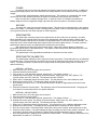
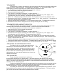
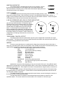
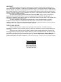
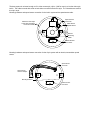
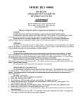
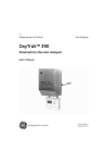
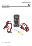
Dakota Digital
SERIES II
VFD DIGITAL INFORMATION SYSTEM
The latest in digital technology for the
motorcycle enthusiast.
INSTALLATION AND OPERATION MANUAL
Please read this before beginning installation or wiring.
MODEL HLY-2000
SPEEDOMETER/TACHOMETER
INFORMATION SYSTEM
Dakota Digital
3421 W. Hovland Ave.
Sioux Falls, SD 57107
Phone: (605) 332-6513
FAX: (605) 339-4106
POWER
Connect the red wire from the main harness to accessory power from the ignition switch. In addition to
powering the display system, this is also where the low voltage detection circuit monitors the electrical system
voltage.
A good quality, solid state ignition switch should be used. The contacts on a mechanical “bar” switch
can bounce due to the vibration and cause the system to momentarily loose power and reset itself.
Never connect this to a battery charger alone. It needs to have a 12 volt battery connected to it.
Battery chargers have an unregulated voltage output that will cause the system to not operate properly.
GROUND
The black wire is the main ground for display system. This should be connected directly to the negative
cable on the battery. Connecting to a tank or frame ground can cause a weak or intermittent ground connection.
A poor ground connection can cause improper or erratic operation.
SPEEDOMETER
The speed input connector plugs into the speed sensor to tell how fast you are traveling. On cable
driven applications, the external sensor connects to the speedometer cable and provides the electric signal.
The sensor is normally bolted directly to the bottom of the speedometer, but can also be remote mounted. The
sensor has a 5/8” course thread fitting that accepts mid-80’s and earlier cables directly. For newer cycles the
speedometer cable will need to be replaced with one having the correct fitting.
With transmissions having the built-in electric sensor, a three-wire harness adapter connects the
transmission speed sensor to the speedometer. This system will also accept most after-market inductive, Halleffect, or ground switch sensors.
The speedometer is fully adjustable and calibration is discussed in a later section.
SPEEDOMETER CALIBRATION
The speedometer calibration is done using the function (trip) switch. The speedometer can be calibrated
two different ways. The first method is to place the unit in auto-cal mode and drive exactly one mile (one km for
metric). The second method is to place the unit in adjust mode and the speed reading can be moved up or
down while driving.
1.
2.
3.
4.
5.
6.
7.
8.
1.
2.
9.
10.
3.
4.
5.
6.
7.
METHOD 1, AUTOCAL
Make sure the key is off so the gauge is not powered.
Press and hold the function switch.
Turn the key on. With the switch still held, start the bike. The display will show “ -- “.
Release the function switch. The display will switch between “AUtO” (auto cal), “AdJ” (adjust), “CYL”
(cylinder select), and “SEt” (shift bar). The odometer will show “SELECt”
When “AUtO” is displayed press the function switch. This will place the unit in auto calibration mode.
Release the function switch. The odometer display will show all zeroes.
Drive exactly one mile (or 1km). The odometer will show the number of signal pulses received from the
speed sensor.
Press and release the function switch. The calibration value will be calculated and stored. The gauge will
now restart in normal mode with the new speed calibration.
METHOD 2, ADJUST SPEED
Make sure the key is off so the gauge is not powered.
Press and hold the function switch.
Turn the key on. With the switch still held, start the bike. The display will show “ -- “.
Release the function switch. The display will switch between “AUtO” (auto cal), “AdJ” (adjust), “CYL”
(cylinder select), and “SEt” (shift bar). The odometer will show “SELECt”
When “AdJ” is displayed press the function switch. This will place the unit in calibration adjustment mode.
Release the function switch. The display shows the speed and the odometer will show “AdJUSt”
Drive at a known speed. Following another vehicle that is driving at a constant, known speed can do this.
Press the function switch. The speed reading will begin increasing until the function switch is released. The
next time the function switch is pressed, the speed reading will begin decreasing until it is released.
Once the speedometer is reading correct release the function switch. The new calibration will be saved if no
adjustments are made for 7-10 seconds.
TACHOMETER
The tachometer is used by connecting the yellow wire from the main harness to the negative side of the
coil or to an ignition module tach output. The tachometer is adjustable for 1, 2, or 8 cylinder settings. The 1
cylinder setting is used for single-fire ignition systems without a buffered tach output.
The following instructions are used to set the tachometer calibration:
1. Make sure the key is off so the gauge is not powered.
2. Press and hold the function switch.
3. Turn the key on so the gauge is powered. The display will show “ -- “.
4. Release the function switch. The display will switch between “AUtO” (auto cal), “AdJ” (adjust), “CYL”
(cylinder select), and “SEt” (shift bar). The odometer will show “SELECt”
5. When “CYL” is displayed press the function switch. This will place the unit in the tach calibration mode.
6. Release the function switch. The display will switch between “1CYL”, “2CYL”, and “8CYL”. The tach bar will
light up two bars above the corresponding number.
7. When the desired setting is displayed, 1, 2, or 8, press the function switch. The display will show “tACH”.
8. Release the function switch. The system will now start up normally with the new setting.
TACHOMETER RED LINE/SHIFT INDICATOR
A single bar will light up to indicate a shift point or red line. The rpm where the bar lights up is user
selectable and can be turned off completely if desired. The bar is factory set to about 5000 rpm.
The following instructions are used to set the tachometer warning bar:
1. Make sure the key if off so the gauge is not powered.
2. Press and hold the function switch.
3. Turn the key on so the gauge is powered. The display will show “ -- “.
4. Release the function switch. The display will switch between “AUtO” (auto cal), “AdJ” (adjust), “CYL”
(cylinder select), and “SEt” (shift bar). The odometer will show “SELECt”
5. When “SEt” is displayed press the function switch. This will place the unit in the shift/red line set mode.
6. Release the function switch. The bar display will start at 2 and begin moving up. After it reaches the top it
will go out and then start back at 2.
7. When the desired rpm setting is displayed press the function switch. To disable this feature, press the
function switch while the bar is not displayed. The display will show “tACH” once the new setting is stored.
8. Release the function switch. The system will now start up normally with the new setting.
Tach
warn
TURN SIGNAL & HIGH BEAM INDICATORS
The right turn, left turn, and high beam indicators are
activated by 12 volts at their respective hook-up wires. The
right turn signal wire is green, the left turn signal wire is orange,
and the high beam wire is purple. These can be connected to
the same wires that the indicator lights are connected to. The
display system wire colors may not match the wire colors in your
electrical wire harness.
Left
Turn
Right
Turn
High
Beam
TRIP ODOMETER
The trip odometer is activated by the push button
function switch supplied with your display system. The button mounts into the opening for the analog
speedometer trip reset that is located on the right side of your speedometer housing (left side on 1995 and
newer). Connect one wire from the function switch to a ground terminal and connect the other wire to the
white/blue wire from the display system.
Pressing and releasing the button will toggle the display from the odometer to the trip odometer or from
the trip odometer to the odometer. Pressing and holding the button while the trip odometer is displayed will
reset the trip odometer. The trip odometer will read from 0 to 999.9 miles.
The sealed push button function switch supplied with the system will operate the trip odometer. It can
be mounted into the hole where the trip reset handle was on your original speedometer. The function switch
goes on the inside and the sealed switch cap attaches from the outside.
NEUTRAL INDICATOR
The neutral indicator is activated when the blue wire is grounded. Connect
this wire to the neutral switch or to the negative side of the neutral indicator light.
When the indicator is activated, a bar on either side of the odometer display will move
up and down as shown in the diagram.
NIGHT DIMMING
Your display system has a dimming feature that dims the display intensity. Normally the system is at full
brightness for daytime viewing. When the brown wire has 12 volts the display intensity will be reduced. A
toggle or on/off push button switch can be connected to this wire if this feature is desired. To have the system
at full brightness all of the time leave the brown wire disconnected.
LOW OIL PRESSURE AND LOW VOLTAGE INDICATORS
The low oil pressure warning is activated when the
gray wire is grounded and there is a tachometer signal.
Connect this wire to the oil pressure switch or the negative
side of the oil warning light. The low voltage warning is
activated when the voltage at the red power wire drops
below 11 volts and there is a tachometer signal. The
warning message will be displayed in the odometer area.
Press the function switch will clear the warning and return
the mileage reading for 30 seconds. If there is both a low
voltage and low oil warning at the same time, the low oil will
be displayed.
TURN SIGNAL CANCEL OUTPUT
The display system also has a speed output signal for cycles equipped with an automatic turn signal
cancel module. The white wire from the main harness should be connected to the module where the wire from
the original analog speedometer was connected.
WIRING
In order to ensure that there are no problems with voltage drops causing the system to shut down, a
heavy duty, solid state ignition switch is recommended. Also, the black wire should be connected directly to the
negative battery terminal to avoid erratic operation due to a poor ground connection.
The wire color code for the main display system harness is as follows:
RED
+12 volt with key on
BLACK
ground (connect directly to battery)
YELLOW
tachometer signal
PURPLE
high beam indicator
ORANGE
left turn indicator
GREEN
right turn indicator
BLUE
neutral indicator
GRAY
oil warning
WHITE/BLUE function (trip select/reset) switch
WHITE
turn signal cancel signal (to auto cancel module)
BROWN
night dimming
Speedometer connection varies depending on the year and model of the cycle. Using different speed
adapter kits the speedometer can read a speedometer cable, a stock electric transmission speed sensor, or an
aftermarket gear-tooth sensor. Each adapter kit connects to the speedometer using the three pin connector on
the bottom of the system.
The cable adapter accepts a 5/8” thread fitting and can be mounted to the bottom of the system using
the supplied bracket or remote mounted. Cycles that have a metric-threaded speedometer cable will need to
have the cable modified or replaced.
The adapter harness for using a stock transmission speed sensor converts the triangular connector to
the in-line connector on the speed/tach system.
The gear-tooth sensor kit consists of a two-terminal sensor and a harness to connect it to the
speed/tach system. The sensor needs to be mounted within 1/8” of the teeth on a final drive gear.
WARRANTY
All DAKOTA DIGITAL instruments are warranted free of defects in material and workmanship for 3
years from the date of purchase. In the event of a problem with one of our products within the warranty period,
DAKOTA DIGITAL will replace or repair the instrument at no charge. (The decision to repair or replace is solely
that of DAKOTA DIGITAL. DAKOTA DIGITAL is not responsible for shipping costs of products returned under
warranty or for labor charges for product installation and removal.) This warranty becomes invalid if the product
is misused, altered or installed incorrectly.
For warranty coverage, you must first call to receive an RMA#. Ship the product transportation
prepaid via UPS or insured Parcel Post. A copy of the original invoice or dated bill of sale along with a
description of the defect is also required. Make sure that the RMA number is clearly visible on the outside of the
package as well as inside on the paper work.
The above warranties, both expressed and implied, do not cover damages caused by improper
installation, misuse, abuse, fire, unauthorized modifications, floods or acts of God, or reimbursement of
customer or shop time. The extent of the warranty is limited only to the product and does not cover any loss or
damage to vehicle, equipment, or non-DAKOTA DIGITAL products.
SERVICE AND REPAIR
DAKOTA DIGITAL offers complete service and repair of its product line. In addition, technical
consultation is available to help you work through any questions or problems you may be having installing one
of our units.
Should you ever need to send the unit back for repairs, please package the product in a good quality
box along with plenty of packing material. Ship the product by UPS or insured Parcel Post. Be sure to include
your RMA#, a complete description of the problem, your full name and address (street address preferred), and a
telephone number where you can be reached during the day. A return authorization number (RMA#) for
products being return for repair is required. Do not send any money. We will bill you for the repair charges.
Dakota Digital
3421 W. Hovland Ave.
Sioux Falls, SD 57107
Phone: (605) 332-6513
FAX: (605) 339-4106
The base system is universal enough to fit in either a new-style, clip-in (1995 or newer) or into the older style,
bolt-in. The rubber mounts with studs on both sides are used for the bolt-in style. The L-brackets are used for
the clip in style.
Mounting hardware and speed sensor connection for the bolt-in system with a speedometer cable.
Attach the foam tape
to the case just below
the chrome bezel.
Speed Sensor
Connector
Cable Driven
Speed Sensor
Rubber
Mounting
Studs
Main Harness
Connector
Mounting hardware and speed sensor connection for the clip-in system with an electric, transmission speed
sensor.
Speed Sensor
Connector
Speed Sensor
Harness Adapter
Mounting Brackets
Main Harness
Connector