1
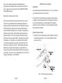
User’s Handbook
TA100/TD101
SmarTach Plus / SmarTach Plus Diesel
Caution: Read this first !
INDEX
CAUTION: Read this First
Page 1
OVERVIEW
Page 2
SHORT INSTRUCTIONS
Page 4
DETAILED INSTRUCTIONS
Battery and Auto Power Off
Page 6
Page 6
TACHOMETER FUNCTION
Display sequence overview
Setting Number of Cylinders
Setting Number of Cycles
Special Considerations
Taking Tach Readings
Page 7
Page 7
Page 7
Page 8
Page 10
Page 11
ANALYZER FUNCTION
Safety Note
Taking IP Readings
Diagnostic Using IP Readings
Special Considerations
Page 13
Page 13
Page 13
Page 15
Page 17
SPECIAL CASES
Shielded Spark-Plug Wires
Inboard Marine Engines
Motorcycles, Ski-doos and Jet-Skis
DIESEL (Model with Diesel adapter)
Short Instructions
Detailed Instructions
Page 19
Page 19
Page 19
Page 20
Page 21
Page 21
Page 22
CARE OF YOUR SMARTACH +
Page 26
THE SMARTACH PLUS IS DESIGNED TO TEST VEHICLES
WHILE THE MOTOR IS OPERATING, SO IT IS IMPORTANT
THAT ALL SAFETY PRECAUTIONS ARE CAREFULLY
OBSERVED, INCLUDING THE FOLLOWING: BEFORE
STARTING THE MOTOR, ENSURE THAT TRANSMISSION IS
IN PARK OR NEUTRAL, EMERGENCY BRAKE IS SET AND
VEHICLE EXHAUST IS VENTED OUTSIDE THE SERVICE
BAY. AVOID CONTACT WITH MOVING PARTS (COOLING
FAN AND DRIVE BELTS) AND HOT COMPONENTS (EXHAUST
SYSTEM). WHEN CHECKING THE SPARK SYSTEM, USE A
CLEAN RUBBER GLOVE TO HOLD THE SMARTACH PLUS
BY ITS PLASTIC BOX. AVOID TOUCHING THE SMARTACH
PLUS ANTENNA WHILE IT IS CONNECTED TO A SPARK
WIRE OR WHILE PROBING ANY PART OF THE SECONDARY
IGNITION SYSTEM.
Page 1
TACHOMETER AND SPARK ANALYZER
OVERVIEW
The SmarTach+ is a professional pocket sized instrument
which combines a tachometer function with the ability to provide information on the voltages found in the spark-plug wires
of spark ignition motors.
Unlike any other tachometer, the SmarTach+ does not need
contact with any part of the motor or a clear view of rotating
parts, to display the rotational speed of the motor in revolutions per minute (RPM). The SmarTach+ works by sensing
radio transmissions from the motor’s ignition system and analyzing these signals with a powerful microprocessor to display
the motor’s RPMs digitally on its Liquid Crystal Display screen.
To display motor RPMs just raise the vehicle’s hood and operate the SmarTach+ while holding it above the ignition wires.
Depending on the position of the ignition wires, it may be possible to lay down the SmarTach+ on some convenient place
near the motor, for example on top of the air-filter.
To check the voltages in the spark-plug wires, just “hook” each
spark-plug wire in turn using the sensor hook on the end of the
SmarTach’s antenna. Read the approximate kilovolts in each
wire on the digital display screen and look for any unusual voltages.
gested and inaccessible situations found under the hoods of
newer models.
When checking the performance of the secondary ignition
system with the SmarTach+ it is usually easy to find and hook
spark-plug wires to locate any malfunctioning wires or sparkplugs. The alternative of removing all spark- plugs and wires
for visual inspection could be very time consuming.
Technical Characteristics:
•
•
•
•
•
•
•
•
Display: 4-1/2 Digits, w/Low Battery indicator
Tachometer Range: 200 to 19,999 RPM ± 0.5%
Cylinders Range: 1, 2, 3, 4, 5, 6, 8, 10 and 12.
Cycles (Strokes) Range: 2 and 4.
Ignition Peak Voltage Range: 0 to 39.9 Kvolt
Power supply: 9 Volt alkaline battery,
Battery life (approx.): 200 hours of continuous operation.
Power saving: Auto Power Off.
The “no wires, no clips, no connections” feature of the SmarTach+ allows the technician to obtain RPM readings immediately, without the need to study where to connect the instrument.
This is a great time saver when dealing with the often conPage 2
Page 3
SHORT INSTRUCTIONS
Spark Analyzer Function/Short Instructions
You are encouraged to read ALL of this instruction book before starting to use your SmarTach+. However, for those who
don’t wish to do this, abbreviated instructions are as follows:
1. Be safe. Use rubber gloves for this test.
Open battery drawer at back of unit. Factory supplied battery is stored in reversed disconnected position. Remove, turn
around and connect the battery.
2. Hold instrument by its box and extend the antenna.
3. Do not touch antenna during tests.
4. Hook antenna sensor over a spark-plug wire, near to
the plug.
Tachometer Function/Short instructions.
5. Read approximate voltage of ignition pulse peak in
kilovolts (KV).
1. Hold instrument by its box and extend the antenna.
6. Repeat for all spark-plug wires and compare results to
locate and identify problems.
2. Do not touch antenna during tests.
3. Press TACH button repeatedly to select correct number of
cylinders.
7. Instrument will switch off automatically after use.
4. Pause.
5. When rotating “cycles” symbol appears, press TACH again
if necessary to choose 2 or 4 cycle systems. (Use 2 cycle
setting for DIS distributorless ignition systems).
6. After setting cycles, wait for 0000 display to appear.
7. Hold antenna about one foot above the ignition system.
Read motor speed in revolutions per minute (RPM).
Instrument switches off automatically after use.
Page 4
Page 5
BATTERY
DETAILED INSTRUCTIONS
TACHOMETER FUNCTION
Overview of the set up display sequence
The SmarTach+ is powered by an alkaline 9 volt battery. A
battery is supplied (reversed) in the battery compartment. Just
turn it around and connect it. The battery is good for hundreds
of tests but will eventually need to be replaced when the ‘LO
BAT ‘ sign starts flashing in the top left corner of the display.
To replace the battery, slide open the drawer at the back of the
instrument and replace the battery with a 9 volt alkaline battery
from a quality manufacturer such as Duracell (Part # MN1604)
or equivalent.
AUTO POWER OFF
The SmarTach+ incorporates an Automatic Battery Shut-Off
system. This means the unit will switch off its own power
about ONE MINUTE after the last button has been pressed,
or about ONE MINUTE after the last signal has been received
(RPM or Ignition Peak Voltage). Because of this, no OFF
switch is necessary, and none is provided.
1. Press the button marked TACH and observe the display
as it moves through the complete display sequence. The
first display will show a number followed by the letters
CYL for “cylinders”. Example: “4 CYL” or “8 CYL”.
2. After two seconds the display will change to show a
rotating symbol with the number 2 or the number 4. This
refers to 2 cycle or 4 cycle motor systems. After two more
seconds, the display will change again to show “0000”.
This “0000” display will be held until an ignition signal is
received.
3. If no reading is performed within one minute, the unit will
shut-off automatically, and the display will go blank. To
repeat the display sequence just press the TACH
button again.
Setting the number of cylinders:
The first press of the TACH button powers up the tester and
displays the setting for the number of cylinders of the last motor tested. If the number of cylinders displayed is correct for
your next test, no action is required.
If the number of cylinders displayed is not correct for the engine you are going to test, the setting must be changed.
To change the setting, quickly press the TACH button again.
The cylinder display will change. Keep pressing TACH
Page 6
Page 7
repeatedly or hold down the TACH button until the correct
display is obtained. Repeated quick button pressing is faster
than holding down the button. Your choice of cylinders is:
1CYL, 2CYL, 3CYL, 4CYL, 5CYL, 6CYL, 8CYL, 10CYL
and 12CYL.
This list of available cylinder settings will repeat if you continue
to press TACH after 12CYL.
In order to be speedy in normal (experienced) use, the time
available to make a selection of cylinders is arranged to be
short. You must be quick in pressing the TACH button when
changing the cylinder settings.
If you hesitate too long in making your choice of cylinders, the
display will switch to the next setting selection which is the
choice of 2 or 4 cycle type ignition systems. If this happens before you have finished setting the correct number of cylinders,
just wait until the display switches to the “0000” reading. As
soon as you see the “0000” display, press the TACH button
again to resume your cylinder selection.
It is necessary to set the correct ignition cycle on the display by
pressing the TACH button to switch between 2 and 4.
If you hesitate too long in making a change of cycles, the display will switch to the “0000” reading. If this happens while an
incorrect cycle number is displayed, just press TACH once and
wait while the display switches back to the setting you made
for cylinders and then switches to the cycle selection again. At
this point one quick press of the TACH button will change to
the correct cycle number.
After setting cycles, the display will switch to “0000”. This
means that the SmarTach+ is now ready and listening to
receive signals from the engine’s ignition system. If no signals
are received within one minute, the SmarTach+ power supply
will automatically switch off and the display will go blank. If
this happens, your settings of cylinders and cycles are not lost
because they are preserved in the SmarTach+ memory.
The settings memory means that when you switch on again
(by pressing TACH once quickly), it will not be necessary to set
the instrument again, unless you are going to test a different
type of engine.
Setting the numbers of cycles (strokes):
After you have set the correct number of cylinders, stop pressing TACH and wait. After two seconds the display will switch
to the next function, which is the selection of ignition system
types. You will see a rotating symbol signifying “cycles”, followed by the numbers 2 or 4. These numbers refer to two
or four cycle ignition systems (sometimes referred to as “two
stroke” or “four stroke” systems).
Page 8
The settings memory feature is useful when a technician is
mostly working on one type of engine, because his usual settings (the last ones set when the instrument switched off) are
memorized and will come up again when the instrument is
switch on.
Page 9
Special Considerations
is indicating a speed of about 1200 RPM it should be reset to
the 2-cycle setting for a distributorless system.
Until a few years ago it was simple to decide whether the cycle
setting should be at 2 or 4. With few exceptions, only some
motorcycles, lawnmowers and outboard motors would have
needed a 2 cycle setting on the SmarTach+. Most motor vehicles use 4-stroke engine in which the ignition system supplies
pulses to the plugs ONLY near the tops of the compression
strokes. This means that each cylinder receives a spark pulse
every second revolution of the crankshaft.
Today, many of the newer vehicles employ DISTRIBUTORLESS IGNITION SYSTEMS (DIS) where each plug is fired
every time its piston approaches TDC (Top Dead Center). In
these systems, a plug fires not only near the top of the compression stroke, but also again a second time near the top of
the exhaust stroke. This second spark is sometimes referred
to as the waste spark because it performs no useful function.
Because the SmarTach+ detects ALL spark pulses, if the
SmarTach+ is set at 4-cycle, it will show correct RPMs on the
traditional distributor systems, but will show TWICE the correct
RPMs on a motor with a distributorless ignition system. For this
reason, when setting up the SmarTach+ to test a motor having
a distributorless ignition system you must set the cycles at 2,
although the motor is operating on a 4-stroke cycle.
In case of doubt concerning whether or not the motor is “distributorless”, an experienced technician will easily detect an
incorrect cycle setting by taking a reading at idle speed. Most
motors are set to idle at about 600 RPM and the sound of this
idle speed is familiar to the experienced ear. If the SmarTach+
Page 10
After set-up of the SmarTach+ for cylinders and cycles, check
the instrument’s display. If it shows “0000” you are ready to
start. If the display has switched off, press TACH briefly to
switch on again and wait while the display switches through
“cylinders” and “cycles” to show “0000”.
(Note that when the SmarTach+ switches off, the last settings
for “cylinders” and “cycles” are retained in the instrument’s
memory and will appear again when it is powered up again)
Taking tachometer readings
1. To take RPM readings after the set-up has been com
pleted, extend the instrument antenna and hold the
SmarTach+ by its plastic case. Do not touch the antenna.
2. Place the end of the antenna near (but without touching) a
place were the spark-plug wires are grouped together, like
a distributor cap, coil packs, etc. At this point the display
should show “0000”, as the signals from the ignition
systems are overloading the instrument.
3. Move the antenna slowly away from its position, until you
obtain a steady RPM reading. If you do move the antenna
quickly, the instrument will be unable to adjust to the rapid
changes, and as a consequence it will not provide steady
readings if any at all.
4. After obtaining the first reading, you may want to continue
to move the antenna further away, in order to locate the
Page 11
SmarTach+ in a more comfortable position or to a conve
nient resting place (i.e. air filter, etc.). If while doing it, the
display start to shows “0000”, then you have moved the
antenna to a distance or place in which the signal has
become too weak to be detected by the instrument. Try to
move the antenna closer to the ignition system or
try rotating the SmarTach+, until the RPM reading is
reestablish.
Note:
In a few cases where the ignition system is partially shielded
by metal parts, the working range of the SmarTach+ will be
more restrictive. it also may be necessary to move the SmarTach+ closer to the spark-plug wires to get a reading.
If the antenna is placed too close to the spark system, the signals may overload the instruments and the display will switch
to “0000”. Just move the antenna further away to resume
readings. If you decide to lay the SmarTach+ down on a
nearby resting place to have both hands free to make adjustments, please make sure that the antenna is not touching any
metal part and that motor vibrations cannot cause the SmarTach+ to move or fall.
Because the instrument’s microprocessor is making continuous
mathematical averages, the display will be interrupted during
rapid acceleration or deceleration. The display will resume
when a fairly steady speed is re-established. The SmarTach+
has the capability of reading motor speeds up to 19,999 RPM,
which cover all possible needs in piston engines.
SPARK ANALYZER FUNCTION
In addition to its primary function as a tachometer, the SmarTach+ has the ability to indicate the relative strength of the
ignition pulses in spark-plug wires.
SAFETY NOTE! Secondary ignition systems are capable of
generating very high voltages which are potentially dangerous.
Many automotive technicians will have experienced electrical
shocks from ignition systems and most of these experiences
may have been no more than unpleasant “jolts”. However,
under certain conditions, shocks from ignition systems can be
dangerous and even lethal.
The degree of severity of ignition shocks can vary depending
on several factors including how well the person is grounded
and the person’s health condition.
It is always advisable to take all available precautions to avoid
electrical shocks when working around ignition systems. The
best way to ensure safety is to wear clean undamaged electrically insulating gloves. We strongly recommend this procedure
at all times when using the SmarTach+ in its Spark Analyzer
mode. BE SAFE.. NOT SORRY !
Taking IP Readings
To check the balance of the spark system proceed as follows:
1. Put on a pair of clean undamaged insulating rubber gloves.
2. Extend the antenna of the SmarTach+ and hold the
instrument only by its plastic box. Do not hold or touch the
antenna during the test.
3. Press the PEAK button. The display will show IP (for
Ignition Peak) and “0.0”
Page 12
Page 13
4. The end of the antenna is provided with a special sensor
which is designed to hook over spark-plug wires. This
sensor can be rotated on the antenna to more easily fit to
the wires. Hook this sensor on the spark-plug wire for
number one cylinder, as near a possible to the spark plug.
Pull gently on the antenna at right angles to the spark-plug
wire to seat the wire in the groove of the sensor.
5. Observe the IP (Ignition Peak) reading of the display.
Some jumping of the readings is normal and reflects actual
changes in the peak voltages of the ignition system.
6. Record or memorize the average reading. Repeat the test
for each of the spark-plug wires of the motor and note
any readings that are significantly higher or lower than
the average.
7 Ignition problems usually increase with motor speed and
may not show at idle speed. We recommend that the
spark analyzer test be made at increased motor RPMs,
equivalent to highway speeds, typically about 3,000
RPM.. Do not exceed maximum permissible (“red-line”)
motor speeds. Make all voltage test at about the same
motor speeds. Use the SmarTach+ tachometer function
to check the RPM.
Each reading is approximately equivalent to the peak voltage
present in the core of the spark-plug wire at the point you have
“hooked”. This reading is proportional to the kilovolts (KV)
required for the coil to initiate a spark across the plug gap, or
elsewhere in a defective system.
Page 14
Diagnostic using the Ignition Peak readings
It is normal for readings on different spark wires to vary slightly
due to small variations in the contact area between the sensor hook and thickness of insulation of the wire. The contact
position of the sensor on the spark wire can also cause some
variation, for example, if the sensor is put on the spark wire
nearer to the distributor or to the DIS coil, slightly higher voltages readings will result.
Conversely, if the sensor is placed nearer to the spark plug on
the same wire, slightly lower voltage readings will result. This
is due to voltage drop along the wire caused by the resistance
of the wire. For diagnostic purposes, the attention should be
focused on SIGNIFICANT DIFFERENCES in readings caused
by problems in the engine or the ignition system itself. For example, on a six cylinder engine, the following varying readings
would be considered as NORMAL because the differences are
NOT SIGNIFICANT.
CYLINDER #1 #2
READING 22.1 23.0
#3
22.6
#4
21.9
#5
22.8
#6
22.5
The above readings are quite close to each other, so no likely
problems are indicated. By contrast, the following varying
readings show ABNORMAL SIGNIFICANT DIFFERENCES in
cylinder #3 and #6.
CYLINDER #1
#2
#3
READING 22.3 21.9 10.4
#4
22.8
#5
22.9
#6
35.6
Except for cylinder #3 which is significantly LOW, and cylinder
#6 which is significantly HIGH, other cylinders are normal. Possible problems are to be suspected at cylinders #3 and #6.
Page 15
Common Causes of Low Voltage Readings
Low voltage readings could be caused by any one of the following problems, or a combination of more than one of these
problems:
the plug and the test point.
•
Lean mixture. Most likely due to inoperative injector or
restriction in fuel injector.
•
Lean mixture due to vacuum leak.
•
•
•
Shorted or dirty spark plug gap.
Dirty spark plug insulator allowing spark “tracking” across
insulator .
Carburetor Engines
•
•
Shorted spark-plug wire.
•
Short circuit, disconnection or partial disconnection
between the distributor (or DIS coil) and spark-plug wire .
•
•
Rich mixture. Most likely due to leaking fuel injector.
Differences between cylinders due to rich or lean mixtures are
unlikely in single carburetor engines except for the possibility
of a lean mixture caused by a leaking gasket between the
cylinder head and the inlet manifold. However, in multi-carburetor engines, an imbalance between carburetors could cause a
difference in readings between the groups of cylinders served
by each carburetor.
Spark plug gap too small.
Broken core in spark plug wire. Break is located between
the distributor (or DIS coil) and the test point.
Low cylinder compression pressure. Could be caused by
leaking valve(s), worn piston rings, blown cylinder head
gasket, etc.
Common Causes of High Voltage Readings
High voltage readings could be caused by any one of the following problems, or a combination of more than one of these
problems:
• Spark plug gap too wide.
•
Spark plug wire cap loose on spark plug terminal or totally
disconnected.
•
Broken core in spark plug wire. Break is located between
Page 16
Special considerations:
Spark-Plug Wires
Due to variations in insulation and core resistance of sparkplug wires from different manufacturers the spark analyzer
cannot be used to accurately read the exact voltage in a sparkplug wire. What it can do, is show by comparison, which wires
are operating at a higher or lower voltage than the remainder of
the wires in the engine. However, it can only do this when the
spark wires are identical. If an engine has been fitted with a
variety of dissimilar wires the usefulness of the spark analyzer
will be reduced.
Page 17
DIS Ignition Systems
SPECIAL CASES
Distributorless ignition systems (DIS) may cause significant
differences in Spark Analyzer readings. DIS fires spark-plugs
with both negative and positive pulses and there may be a
wide difference in voltages between the positive and negative
pulses.
Shielded Spark-Plug Wires
For this reason, when performing the Ignition Peak test on DIS
systems, the comparison should only be made between sparkplug wires with the same polarity, either positive or negative.
Unbalanced voltage readings between wires of different polarity may not indicate a problem in this type of ignition systems.
Some vehicles may be fitted with aftermarket “high performance” spark wires. These wires have solid copper cores and
are shielded by metal jackets which prevent transmission of
the radio signals. The SmarTach+ antenna needs to receive
these transmissions in order to perform its tachometer and
spark analyzer functions.
Depending on the efficiency of the shielding it may be possible
to make some assessment of spark voltages sufficient to see
any out of balance situations. In the tachometer mode it is
possible in some cases to pick up a signal if the sensor hook is
used right on the spark wire. However this will give an inaccurate reading because the SmarTach+ will be reading only one
cylinder, whereas you have set the unit for multicylinders. In
case you wish to read RPMs in this way, it is permissible
to do so providing you first set the “CYLINDERS” to 1.
Often it is possible to read RPMs with shielded spark-plug
wires by holding the antenna over the distributor. This way,
the antenna can sense all the sparks and there is no need to
change the “CYLINDER”setting.
Inboard Marine Engines
Many inboard marine engines are supplied from the factory
with shielded spark-plug wires, because of the risk of explo-
Page 18
Page 19
sions due to sparks tracking around damaged wires.
This practice will interfere with the normal use of the SmarTach+. Please see the comments under SHIELDED SPARKPLUG WIRES (above).
Motorcycles, Ski-Doos and Jet Skis
Some of these machines may have motors which are “shoehorned” into a substantial frame so that frame members effectively split the radio transmissions from different plug wires
and the SmarTach+ antenna cannot receive transmissions
from all the wires simultaneously. If possible, try holding the
antenna close to a point where all the spark-plug wires are
grouped together. If this is not possible consider how many
cylinders the antenna cannot detect. Typically this will be half
the cylinders. For example, in a 4 cylinder motorcycle with
a transverse crankshaft, 2 cylinders will be to the left of the
frame and 2 cylinders to the right. When making tests while
standing on the right side of the bike it is likely that the antenna will only detect the transmissions from the two cylinders
on the right. In this case, just set the SmarTach+ to the “2CYL”
setting to start reading correct RPMs.
SMARTACH+ D (Diesel)
OVERVIEW
If you purchased the model SmarTach+ D, it is very important
you read the instructions in this section.
Your SmarTach+ D can measure the speed of diesel engines
in addition to all the measurements of the regular SmarTach+.
It is recommended that you read the SmarTach+ Detailed
Instructions of this handbook first, to become familiar with the
basic method of operation.
SHORT INSTRUCTIONS
1. Clamp the sensor clamp onto a clean unpainted section of
any diesel injection pipe. Do not over tighten the thumb
screw. (see Fig. 1)
Fig. 1 Piezo Sensor Clamp Set Up
Page 20
Page 21
2. Clip the alligator ground clip on the sensor wire onto a
clean unpainted section of the same injection pipe.
pipe. The clamp must make a good electrical connection to
the pipe.
3. Check that battery in the SmarTach+ D is connected.
•
4. Insert the jack plug on the sensor wire into the female jack
connector on the SmarTach+ D.
5. Set the correct engine cycles (4-Stroke or 2-Stroke) by
pressing the TACH button until the correct number is
displayed. Display will then switch to “0000”.
6. Connect the forked terminal to the sensor clamp. Start the
diesel engine and the RPMs will be immediately displayed
on the screen.
7. If no RPMs are displayed check for firm clean connections
at the sensor clamp and the ground clip. If this does not fix
the problem, read sections 2. and 3. in the full instructions
that follow. Do not try to fix a problem by extra tightening of
the thumb screw on the clamp!
8. The SmarTach+D switches off automatically if no signals
are received after one minute.
DIESEL TACH DETAILED INSTRUCTIONS
Please be sure to read the first section of this user’s handbook,
to become familiar with the basic operation of the SmarTach+,
before to proceed with this section.
1. Open the battery drawer at the back of the SmarTach+ D.
Remove, turn around, and connect the clip to the factory
supplied battery.
Scrape and sandpaper the pipe if necessary. If you do
not wish to do this you could wrap a piece of kitchen
type aluminum foil, such as Reynolds Wrap, around the
pipe and clamp the sensor over this foil. Make the foil
wrap long
enough to allow placing of the alligator
ground clip
on the same piece of foil. Use of aluminum
foil will often fix problems due to bad electrical connections between the sensor clamp and the injection pipe.
•
Do not over tighten the clamp . Use of excessive force
or tools such as pliers to tighten the clamp will result in
damage to the piezo crystal and void the guarantee.
Replacement clamps are expensive!
3. Clip the alligator ground clamp (on the end of the connecting wire) onto the same pipe, below or above the sensor
clamp. If this is not convenient, clip the ground clamp to
any other good ground point on the engine.
•
Important Note: If you have used the aluminum foil
method of attaching the clamp (described in 2. above) it
is essential that the alligator ground clamp is clipped to
the same piece of aluminum foil.
4. Pick up the male stereo jack plug (at the opposite end of
the connecting wire) and insert this plug fully into the
female connector on the SmarTach+D. This connector is
located close to the antenna at the top of the
SmarTach+ D box.
2. Fit the sensor to a clean unpainted section of an injection
Page 22
Page 23
•
•
Note: When you insert the stereo jack plug into the
connector, the microprocessor in the SmarTach+ D
automatically switches into the diesel mode. This means
that settings needed for checking gasoline engines, such
the number of cylinders, are no longer required. Also,
operation of the PEAK button will be ignored.
It follows that you must remove this jack plug before
using the unit to check gasoline engines.
5. Press the SmarTach+ button marked TACH. The screen
will display a rotating symbol with a number which will be
either a 2 or a 4 (these numbers refer to whether the diesel
is a 2-stroke or a 4-stroke) .
6. You must set these numbers correctly before taking RPM
readings. To change these cycle numbers, push the TACH
button again quickly while the rotating cycle symbol is
displayed. If the rotating symbol display has switched to
“0000” before you have made a correction , just press the
TACH button again to return to the cycle setting display.
7. After setting the cycles the display will switch to “0000”.
8. Locate the forked terminal at the end of the sensor wire
(near to the alligator ground clip) and push it under the flat
head of the connector pin at the corner of the piezo sensor
clamp. This connector pin is the one with a coil spring.
You will see that this spring presses a conical washer
Page 24
against the flat pin head. The forked terminal must be
inserted between this washer and the flat pin head. Hook
up is now complete.
9. MAKE SURE THAT THE VEHICLE IS NOT IN GEAR AND
THAT THE EMERGENCY BRAKE IS SET. IF TESTING
IS BEING DONE INDOORS MAKE SURE THAT ALL
EXHAUST EMISSIONS ARE PIPED OUTSIDE. CHECK
THAT ALL PERSONNEL ARE CLEAR OF ROTATING
PARTS OR HOT AREAS.
10. You may now start the diesel engine.
11. Press the TACH button once briefly. Watch the screen to
confirm that the cycle setting is still correct. After showing
the cycle setting the screen will switch to showing engine
RPMs.
•
The SmarTach+ D will continue to show RPMs as long as
pulses are being received from the piezo sensor.
The SmarTach+ D will switch off automatically if no signals
are received for one minute, for example, when the diesel
engine has stopped for more than one minute, or some fault in
the sensor system causes a loss of pulses for more than one
minute. To power up the SmarTach+ D again, just press the
TACH button.
NOTE: Incorrect setting of the “cycles” can result in RPM readings that are half the correct speed or twice the correct speed
. When first setting up, listen to the diesel at idling speed
and compare with the RPM reading on the SmarTach+ D. If
the reading seems much too high or much too low, check the
“cycles” setting.
Page 25
CARE OF YOUR SmarTach+
Your SmarTach+ is a precision instrument and should be
treated as such. Damage caused by mistreatment is not covered by the warranty.
Keep the tester in its box when not in use and do not store in
areas subject to dampness or severe heat or cold. Very cold
temperatures will cause permanent black marks on the liquid
crystal display. This is not covered under warranty. Do not
use the tester in the rain. If the tester should accidentally get
wet, dry it off with a clean paper towel before storing it in its
box.
Protect the tester from contact with any solvents. NEVER
clean it with a solvent or petroleum based mediums such as
gasoline, because these chemicals may attack the plastic
parts. Never use an abrasive cleaner. Cleaning should be
limited to wiping with a clean damp paper towel with a small
amount of soap if required. Dry the tester thoroughly after any
cleaning.
The SmarTach+ is a sealed instrument and contains no user
serviceable parts other than the battery which can be replaced
by opening the drawer on the back of the tester.. Opening
other parts of the SmarTach+ will void the warranty.
Page 26
YOUR ONE YEAR WARRANTY
With the exception of the battery, your SmarTach+ is warranted against defects of material or workmanship which
develop within a period of one (1) year following the date of
purchase by the original owner. Proof of date of purchase
will be required when applying for repair or replacement under
guarantee. For this reason we strongly suggest that you keep
your sales receipt safely in your SmarTach+ storage box.
In the event that a fault develops in the SmarTach+ please
return it to your dealer who will arrange repair or replacement.
The manufacturer will either repair or replace the tester (at
the manufacturer’s option) free of charge providing that the
SmarTach+ is still under warranty. If the warranty has expired,
there will be a repair charge payable to your dealer when you
pick-up the repaired tester. When a unit has been repaired or
replaced under warranty, the replacement tester will continue
the warranty period of the original tester for six (6) months after
the date of replacement or until the original warranty expires,
whichever is the longest period. This warranty shall not apply
to any defect, failure or damage caused by improper use or
inadequate maintenance or care.
The manufacturer shall not be obligated to provide service under this warranty or to repair damage resulting from attempts
by unauthorized persons to repair or service the tester, other
than to replace the battery; or to repair damage resulting from
improper use. Specifically if there is evidence of an attempt to
open the SmarTach+ the warranty is void.
Page 27
ANY IMPLIED WARRANTIES ARISING OUT OF THE SALE
OF THE SMARTACH PLUS INCLUDING BUT NOT LIMITED
TO IMPLIED WARRANTIES OF MERCHANTABILITY AND
FITNESS FOR A PARTICULAR PURPOSE ARE LIMITED IN
DURATION TO THE ABOVE ONE (1) YEAR PERIOD, THE
MANUFACTURER SHALL NOT BE LIABLE FOR LOSS OF
USE OF THE TESTER OR OTHER INCIDENTAL OR CONSEQUENTIAL DAMAGES, EXPENSES, OR ECONOMIC LOSS
OR FOR ANY OTHER CLAIM OR CLAIMS FOR SUCH DAMAGES, EXPENSES OR ECONOMIC LOSS.
Some jurisdictions do not allow limitations on how long implied
warranties last or the exclusion of or limitation of incidental or
consequential damages, so the above may not apply to you.
NOTES
Page 28
Page 29
TA100M9605
© Copyright 1993-2001 General Technologies Corp.
Printed in Canada


![AI metro 3200 deutsch 0-1 [Converted].ai](http://vs1.manualzilla.com/store/data/006791316_1-c478ebdf343a8300a17282b5d1eeb3fa-150x150.png)