1
OWNER'S
MANUAL
MODEL
NO.
580.327270
®
CUSTOMER
HELPLINE
_'-\.
-\\
I-soo-===-3136
HOURS:
l
Mon. - Fri. 8 a.m. to 5 p.m
(CST)
I
CAUTION:
'
LRead and Follow
all SafetyRule s L
andlnstructions
Before Operating
This Equipment
...........
L. SEARS'
L
ROEBUCK
Part No. 99372 Revision I (4/2/96)
120 VOLT / 2500 WATT
•
Assembly
•
Operation
•
Customer
°
Service
•
Repair Parts
and
CO.,
Responsibilities
and Adjustment
__
HoffmanEstates,..tL
_ 60179U,S,A,
SAFETY RULES
_
TACT SPARK PLUG, TO PREVENT ACCIDENTAL STARTING WHEN SETTING UP, TRANSPORTING,
AUTION: ALWAYS DISCONNECT SPARK PLUG WIRE AND PLACE WiRE WHERE IT CANNOT CON"
ADJUSTING
OR MAKING.
REPAIRS
TO YOUR
GENERATOR,
_#1_
:: IMPORTANT
THISGENERATOR
IS DESIGNED FOR OUTDOOR USE ONLY. USING THIS GENERATOR INSIDE ANY BUILDING OR
ENCLOSURE, INCLUDING THE GENERATOR COMPARTMENT OFA RECREATIONAL VEHICLE (RV)_ IS DANGEROUS.
FIRE OR AN EXPLOSION MAY RESULT. ,NO USER PERFORMED MODIFICATIONS, INCLUDINGIVENTING
OF EXHAUST
AND!OR COOLING VENTILATION, WILL ELIMINATE THE DANGER.
•
•
•
•
•
•
•
If this unit is used for backup power in the event of
a utility power failure, take the following steps: BEFORE CONNECTING THE GENERATORTO
AN
ELECTRICAL SYSTEM OPEN THE MAIN CtR,
CUlT BREAKER OR MAIN SWITCH SERVING
THE SYSTEM TO ISOLATE THE GENERATOR
SYSTEM FROMTHE ELECTRIC UTILITY. FAIL,
URE TO ISOLATE THE GENERATOR AND UTILITY SYSTEMS MAY RESULT IN DAMAGE TO
THE GENERATOR AND MAY ALSO RESULT IN
INJURY OR DEATH TO ELECTRIC UTILITY
WORKERS DUE TO BACKFEED OF ELECTRICAL ENERGY.
This generator supplies dangerously high electrical
voltages. Use care to preventextremely hazardous
and possibly lelhal electrical shock. Never permit
any unqualified person(s) _ operate or service the
unit.
DO NOT operate this equipment in the rain, while
standing in water, while barefoot, or while hands or
feet are wet. Dangerous electrical shock will result
The spark arrestor muffler can become ex_'emely
hot. DO NOT operate this equipment in areas where
combustible material such as grass, leaves or paper
products can come in contact with the muffler.
Maintain all v.iring, extension cords, etc., in good
condilJon. Worn, bare, frayed, or otherwise damaged wiring and cord sets may cause dangerous
electrical shock and may also result in damage to
equipment and/or property.
The National Etectrcal Code requires thatthe generator be propedy connected to an approved earth
ground. Local electrical codes may also require
proper grounding of the unit See ASS E MB LY secOon for more grounding information.
Wire gauge sizes of wiring and cord sets must be
large enough to handle the maximum electrical load
to v_nich they ,will:be: subjected; Most devices.re-,
quire cord sets rated 125 AC volts at 20 to 30 .....
amperes or 250:AC ,volts at 20 amps (or greater)..: _
Some devices may require a higher or lower ra_ng_ ....
Refer to the Owner's manual of the eleCtrcal device
for the manufacturer's, recommendations.
Cord
•sets that are too small in diameter or too long will
overheat; become damagedand:maycause: prop-.,
erty damage and/or electrical shock.
The genera_r engine,_c0nsumes oxygenand gives
off DEADLY:_carbon monoxide gas through itsex-"
• haust system:;_-'This.dangerous,:gas, if breathed in
LOOK
MEANS
FOR THIS SYMBO:L
"ATTENTION!!!
sufficient concentrations, ican; cause unconsciousness or even death. Operate this equiprr_nt outdoors only, in vveUventilated; areas v_ere exhaust
gases cannot accumutate:andendanger people or
animals.
The engineexhaustf..romthis product
contains chemicals Knownm the State
of California to cause cancer, birth
defects,or other reproductiveharm.
I I
•
•
•
•
•
•
I'111'
III
e,_ DONOT use the unitifit has, been damaged. Repair
, 'or :replace :all damaged i:or :defeclJve .components
before .you run the unit.
I
DO NOT permit children to operate or service the
generator.
Q
Read you_ Owner's Manual carefully. Only persons
who are familiar with these safety rules and have
been propedy instructed:in the use of this product
: shoutdbe _permitted:to: use 1he product
TO' POINT OUT IMPORTANT
BECOME
I'll
Gasoline is extremely FLAMMABLE and its vapors
are EXPLOSIVE.
Comply wit_ all la_ regulating
the storage and handling of gasoline. DO NOT
permit smoking, open flames, sparks or heat in the
vicinity while handling gasoline.
Avoid spilling
gasoline on a hot engine. DO NOT fill fuel tank
while engine is running or hot. Clean offany spilled
gasoline before starting engine.
DO NOT fill fuel tank completely full. _,Jlowroom at
top of tank for fuel expansion or fuel may expand
and overftowonto a hot engine.
Drain all gasoline from tank before transporting,your
generator inside your car or other vehicle.
DO NOT store the generator with fuel in tank where
gasoline vapors might reach an open flame, spark,
or pilot light, as on a furnace, water heater, dryer,
etc. FIRE or an EXPLOSION might result.
DONOT insertany objector toolthrough cooling air
slots or openings of the engine or generator, even
if the engine is not running; Damage to the unit or
personal injury" may result.
DO NOT attempt to change the engine governed
speed.. Factory se_ngs are correct when you receive the unit. Excessively high engine speeds may
result in injury or damage to'equipment
ALERT!!!
SAFETY
YOUR SAFETY
PRECAUTIONS.
IS INVOLVED."
IT
I
I
CONGRATULATIONS on your purchase of a Sears Craftsman Generator.
it has been designed, engineered and
manufactured to give you the best possible dependability
and performance.
Should you experience any problem you cannot easily
remedy, please contact your nearest Sears Service Center/Department or call the 1-800 number listed in this manual. We have competent, well-trained technicians and the
proper tools to service or repair this unit
Please read and retain this manual. The instruc_ons wilt
enable you to assemble and maintain your generator properly. Alvvays observe the 'SAFETY RULES."
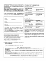
PRODUCT
SPE CIFICATIONS
Generator Specifications
RATED :MAXIMUM
POWER.
2500 Watts (2.5 kW)
RATED VOLTAGE
120 Volts a-c
RATED MAXIMUM
LOAD)CURR ENT
20.8 a-c amperes
RATE DFRE OU EN CY
60 Hz at 3600 rpm
PHASE
Single Phase
MODEL
NUMBER
E ngine Specifications
580.327270
SERIAL
NUMBER
DATE OF
PURCHASE
NANCE
DtSPLAC E ME NT
10.49 Cu. in. (172cc)
SPARK PLUG: Type:
Champion RJ-8C or
or equivalent
0.030 inch (0.76mm)
GASOLINE CAPACITY
3 U.S. quarts
OIL (1-I/4 U.S. pints)
SAE 30 oi!
In the State of California a spark arrestor is required by law
(Section 4442 of the California Public Resources Code).
Other states may have similar lav, s. Federal laws applyon
federal lands.
NOTE: If you equip your generator
with a spark arreslor
muffler, the spark arrestor must be maintained
in effective
working order by the ov_er/operator.
AG R E E ME NT
A Sears Maintenance Agreement is available on this product Contact your nearest Sears store for details.
CUSTOMER
5 at 3600 rpm
Set Gap to:
THE MODEL AND SERIAL NUMBERS WILL BE
FOUND ON A DECAL ATTACHED TO THE GENERATOR STATOR CAN.
YOU SHOULD RECORD BOTH SERIAL NUMBER
AND DATE OF PURCHASE AND KEEP IN A SAFE
PLACE FOR FUTURE REFERENCE.
MAINTE
RATED HORESPOWER
You can order a spark
Service Centsr.
arrestor
muffler
through
your Sears
RESPONSIBILITIES
•
Read and observe the safety rules.
•
Fotlowregular schedule in maintaining, caring for and
using your generator.
•
Followtheinstructionsunder'Maintenance"and
age"sections of this Ovvqer's Manual.
FULLTWO
"Stop
YEAR
WARRANTY
For two years from the da_e of purchase, Sears will repair any defect in material or workmanship in this generator
at no charge.
If the generator is used for commercial or rental purposes, this werranty applies for only ninety days from the
date of purchase:
Warranty-.service is available by returning the generator to the nearest SEARS SERVICE CENTER/DE PARTMENT throughout the United States,
This warranty gives you specific legal rights and you mayalsohave:other
rights; which vary from state to state.
SEARS, ROEBUCK AND CO., DePartment 817 WA, Hoffman Estates, IL 60179
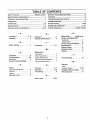
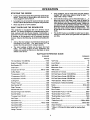
TABLE OF CONTENTS
SAFETY RULES ....._. ................. :.............. INSIDE COVER
MAINTENANCE AGR EE MENT ;;..;.,.;...;.;......... ......... ......17
SERVICE RECOMMENDATIONS
PRODUCT SPECIFICATIONS
TROUBLESHOOTING
........................... ............ 1
................................
10_
POINTS .;....................... ;...:;....
WARRANTY
..............................................
:.....................
1
WIRING DIAGRAM .......................................................
OPERATION ....... ,.................................
................. •..... 3-6
RE PAIR PARTS ............................ ;.......................... 14-20
......................... .......... ,.i ................... 7-8
E MISSIONS WAR RANT'( ............... ,....... ................ 21-22
PARTS ORDERING ........................... ,....... BACK COVER
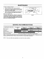
MAINTENANCE.
SERVICE AND ADJUSTMENTS
...............................
-AAir Cleaner .............
Assembly : ...............
9-10
Gasoline .................
Grounding Wing Screw .....
-BBefore Starting ............
S
-G7, 8
4
5
4
L
4
Lubrication ..............
5,7
-MMa inte nance
Agreement ..................
-CCarburetor ...............
Circuit Breakers ..........
Cord Sets ................
Customer Responsibilities
9
5,6
5
...
1
Cleaning
generator.
9
7
Speed ......................
EtecVical Loads ...........
9
5
Oil Level ................
Operation ...............
Overloading
..............
7
7
7
5, 7
3-6
6
-pParts, repair ...........
-T-
7
-O-
E ngine
Carburetor adjusVnent .........
Oit level .....................
Safety Rules ......
inside cover
Service and Adjustments
Carburetor ..................
9
Engine Speed ................
9
Service Recommendations...
9
Specifications ..............
1
Starling Engine ............
5
Stopping Engine ............
6
Storage ..................
9
1
; ;.......,.
Engine maintenance ...........
General Recommendations .....
Generator Mainl_nance........
-E-
13
12-20
Troubleshooting
...........
10
-WWarranty
Parts.......................
1
Emission Convol .........
18-19
Wattage Reference Guide .... 6
Wiring Diagram ...........
11
•
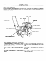
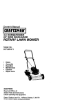
OPERATION
KNOW
YOUR
GENERATOR
R E:AD THiS OWN ER'S MAN UAL AN D SAFE _IR ULE s BE F0R E oP E RATING YOUR G ENE F_AT(3R. Compare i_e i_i
ittustra_onsV_th your generator, to familiarize yourself with 1he locations of various controls and adjustments. Save this
manual for future reference.
FUEL TANK
5 H.P. ENGINE
1
MUFFLER
GUIDE
AIR CLEANER
CIRCUIT
PRIMER SWITCH
CARBURETOR
DUPLEX RECEPTACLES
120 VOLTS 'I_UPLEX" RECEPTACLES -- May be used
to supply electrical power for the operalJon of 120 volts at
20 amps a-c, single phase, 60 Hz, a-c electrical ligh_ng,
applicance, tool and motor loads.
20-AMP A-C CIRCUIT BREAKER m Protects 1he generator against electrical overload. Breaker is "push to reset"
type.
RECOIL STARTER -ally,
Used for sl_rlJngthe engine manu-
AIR CLEANER -- Fit_ers intake air as it is drav_ l_rough
the engine.
FUEL TANK -- Tank holds l_ree U.S. auarts of unleaded
' gas0iine_
" 5 H.P. ENGINE -- Provides the power needed to generate
2400, v_tts of AC output.
3
OPERATION
Your a-c generator was completely assembled at the factory,: itis ready for use after it has been propetivserviced"
with the recommended lubricating oitand fuel.
IF YOU HAVE ANY:PROBLEMS WITH THE ASSE MBLy:
OF YOUR GENERATOR, PLEASE CALL THE GENERATOR HELPLtNE AT 1-800-222-3136.
the grounding lug and 10 an earth-driven copper or brass
;grounding<rod:,.(eleclrode)' pm._des_:adequate protection
_againstelectrical: shock (Fig:, 2L However, local-code,_.
..may!ivary vwide!y; Consult_with a ,local electrician for,
grounding requirements in your area.
IMPORTANT:
ANY ATTEMPT TO RUN THE ENGINE
..BEFORE tT HAS BEEN SERVICED WITH THE RECOMMENDED OIL WILL RESULT iN AN ENGINE FAILURE.
TO REMOVE
GENERATOR
FROM
CARTON
*
Set.the carton on a fiat rigid surface with__H!S SIDE
UP* arrows poin*Jng upward.
:_.
-
Carefully open the top flaps of shipping carton.
-
Cut down corners atone end of shipping carton and lay
that side of carton down flat
•
Remove packing material, carton fillers, etc.
-
Remove generator from shipping carton,
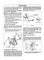
TO ADJUST
GUIDE
-w%9
SCREW --
L.J
GROUNDING ROD
HANDLE
FIG.2
Your generator is equipped with a Wneel kit for easy
manuevedng.
After you remove the generator from the
carton you complete the following tasks to ready 10 generator for use:
...........
•
Loosen knobs ofthe guide handle as shown in Fig. t,
•
Raise the guide handle as also shov_q in Fig. 1 and
_ghten the knobs lO hold the handle in place.
Proper grounding of generator will help
shock in the event of a ground fault
generator or in connected electrical
grounding also helps dissipate static
often builds up in ungrounded devices.
prevent electrical
condition in the
devices, Proper
electricity, which.,
IF YOU HAVE ANY PROBLEMS OPERATING YOUF_
GENERATOR,
PLEASE
CALL THE GENERATOR
HELPLtNE AT 1-800-222-3136.
BEFORE
STARTING
ENGINE
Add Oil:
Place generator on a level surface and remove oil fil!plug.
Fill with SAE 30 detergent oil to point of overflowing for oil
fill plug (Fig. 3). POUR SLOWLY. DO NOT OVERFILL.
Oil capacity of engine is 21 ounces (.62 Liters or 1-1/4 U.S.
)ints).
OIL FILL
PLUG
FIG. t
GROUNDING
THE GENERATOR.
.RG:31 .........
.The Na_tionalElectricat Code requires that. the frame and
external electrically conductive parts of this generator b_,
propedvconnected to. an approved earth ground_,-Loca!I
elec_cal.:codes _mm/_atsOrequir.e,pr.oper grounding of the
unit. For that purpose, a GROUNDING LUG is provided
on the control panel (Fig. 2). Generally,. connecting a No.
12 AWG (American WIre Gauge) stranded copper wire to
When_oilsumpis,futl,:install and tighten oil fill ptug.,Use
:no special:additives _th recommended oils. ""
4
OPERATION
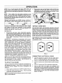
NOTE: Use of multi-viscosity oils above 40OF (4cC) will
result in high oil consumption andpossibtemenginedamage.
Use 5W-30 when Operating the generator in weather below.
32q =.....
o
-.
Grasp star_er grip and pull slo_y until you feel some
resistance. Let rope.retum $1ovvly,_,
Then pull cord out
with rapid full;arm stroke. Let rope return slov_y. Do not
let rope "snap back" against starter, +.
NOTE: W1_en adding oil to the engine .crankcase in the
future, use only high qualitydetergent
oil rated +with AP!.
service classification SF, SG, or SH, ratedSAE ;30 weight.
Select the oil's viscosity grade :according to your expected
operating temperature,
Althoughmulti-viscosity:oils
(5W30) improve starting incold weather, these mullJ+viscosity oils _1t result in incolder5W30
" 3,20
'
!
FIG. 4
warmer
SAE30
120-VOLT
creased oil consumption when used above 32 ° F, Check
your engine oil level more frequendy to avoid possible
damage fTom runnign low on oil, Oil sump capacity is 21
ounces (,62 Liters or 1-1/4 U.S+ pin++s).
•
Fill fuel tank _th clean, fresh, UNLEADED gasoline,
Leaded regular grade gasoline may also be used. DO
NOT USE PREMIUM GASOLINE, DO NOT MIX OIL
WTH GASOLINE. BE CAREFUL NOTTO OVERFILL
FUEL TANK. Allow about 1/4-inch of tank space for
expansion.
IMPORTANT:
EXPERIENCE INDICATES THAT ALCOHOL+BLENDED FUELS (CALLED GASOHOL) CANAT+
TRACT MOISTURE WHICH LEADS TO SEPARATION
AND FORMATION
OF ACIDS DURING STORAGE.
ACIDIC GAS CAN DAMAGE THE FUEL SYSTEM OF AN
ENGINE WHILE 1N STORAGE.
TO AVOID ENGINE
PROBLEMS WHEN USING GASOHOL, EMPTY THE
FUEL SYSTEM BEFORE STORAGE PERIODS OF 30
DAYS OR LONGER. DRAIN THE GAS TANK, START
THE ENGINE AND LETtT RUN UNTIL THE FUEL LINES
AND CARBURETOR ARE EMPTY, USE FRESH FUEL
NEXT SEASON. SEE STORAGE INSTRUCTIONS FOR
ADDITIONAL INFORMATION. NEVER USE ENGINE OR
CARBURETOR CLEANER PRODUCTS IN THE FUEL
TANK OR PERMANENT DAMAGE MAY OCCUR.
Keep extension cords as short as possible, preferably less
than 15 feet long to prevent voltage drop and possible
overhea_ng of wires.
FIG. 6
CONNECTING
NOTE: DO NOTUSE GASOLINE CONTAINING METHANOL (WOOD ALCOHOL), You can use gasolines containing 10% ethanol or grain alcohol. See STORAGE INSTRUCTIONS for more informalJon.
THE
ENGINE
Unplug all electrical loads from generator receptacles before starting the engine. Never start or stop engine v_th
electrical devices plugged into panel receptacles and
turned on.
*
Move engine convol lever to '*START" position (Fig+4).
-
Press the primer bulb three times. Wait
each time you press the primer..
CORDSETS
Use only high quality, wall-insulated, exl_nsion cords _th
the generator's 120-volt"duplex" type electrical receptacles
(Fig. 6), Checkthe ratings of all ex_nsion cords before you
use them. Extension cord sets used should be rated 125
volts at 20 a-c amps or greaterfor most electrical devices,
Some devices, however, may not require 1his type of extension cord. Check the owner's manuals of those devices
for the manufacturer's recommendations.
Add Gasoline:
TO START
FIG: $
2:seconds
NOTE_ The primer may beneeded to restarta- vvarme ngine
after a _Sho_'shutd0wn: _
5
ELECTRICAL
LOADS
-
Use this generator to operate 120 volt, single phase,
60 Hz, a-c lighlJng, appliance, tool and motor loads.
-
DO NOT connect 240 volts.to 120 volts duplex outlets.
•
DO NOT connect any 3-phase loads to-panel receptacles.
Q
DO NOT connect any 50 Hz loads to.the generator.
O
Add up rated watts of aft lights, +toot, +appliance and
motor loads,you are powering at:one time. This total
should NOT be greater than (a) generator's rated wattage capacity, or (b) circuit breaker rating of the recaptacle supplying powar. See 'l_on'tOverload_the Generator" on Page 6,
OPERATION
STOPPING
THE ENGINE
Unplug all electrical loads from generator panel receptacles. Never start or stop engine with electrical devices plugged in and lumed on.
•
Let engine run at no-load for several minutes to stabi..... lize the internal temperatures of engine and generator.
=
If the appliance, tool or motor does not give wattage,
multiply 120 volts times ampere rating to deter
_e
v_tts (volts x amps =watts).
*
Some electric motors, such as induction types, re_ ,,re
about two and a half times more watts of power for
starting than for running. This surgeofpowerlasts only
a fewseconds when starting such motors. Make sure
you allow for this high starting wattage when selecting
electrical devices to connect to your generator, First,
figure the watts needed to startthe largestmotor. Add
to that figure the running watts of all other connected •
loads.
=
The GUIDE below is provided to assist you in determining how rnany items your generator can operate at
one time.
•
•.
Move stoP'lever'to *OFF" position.
DON'T
OVERLOAD
THE
GENERATOR
This': generator is equipped with one 20-amp circuit
breaker. The duplex receptacle is protected against elec_cat ovedoad with the 20-amp breaker. Overloading a
generator in excessof its rated wattage capacity can result
in damage to the generator and to connected electrical
devices. Observe the following, lo prevent overloading the
unit:
e
Add up the total watlzge of all electrical devices to be
connected at one time. This total should NOT be
greater than the generator's wattage capacity.
•
The rated wattage of lights can be taken from light
bulbs. The rated wattage of tools, appliances and
motors can usually be found on a data plate or decal
affixed to the device.
WATTAGE
REFERENCE
GUIDE
RUNNING
RUNNING
WATTS
WATTS
*Air Conditioner (12,000 Btu) ...... _.............................
1700
*Jet Pump ...............................................................
"30
Battery Charger (20 amp) ............................................
500
Belt Sander (3") .........................................................
1000
Lav_ Mower .............................................................
Chain Saw .................................................................
Microwave Oven .........................................................
1200
YO
Light Bulb ...................................................................
_00
700
Circular Saw (6-1/23 .................... ,................. 800 to 1000
ffVlilk Cooler ...............................................................
Coffee Maker .............................................................
1000
Oil Burner on Furnace .................................................
*Compressor (1 HP) ....... ,..........................................
2000
Oil Fired Space Heater (140,000 Btu)......................... 400
*Compressor (3/4 HP) ...............................................
1800
Oil Fired Space Heater (85,000 Btu) ...........................
225
*compressor
(1/2 HP) ...............................................
1400
Oil Fired Space Heater (30,000 Btu) .............................
50
Curling Iron ..................................................................
700
*Paint Sprayer, Airless (1/3 HP) ..................................
600
_Deep Freeze ..............................................................
500
Paint Sprayer, Airless (handheld) ...............................
150
Disc Sander (9") ........................................................
1200
Radio ..................................................................
1100
300
50 to 200
Edge Trimmer ........................... ................... ;............... 500
Electric Nail Gun ............................................ -.......... 1200
4Refrigerator ................................................................
600
Slow Cooker .................................................................
200
Etectric Range (one element) .................................... 1500
E le ctri(_Skillet.:. J..... .............................. ..................... 1250
"Submersible Pump (1-1/2 HP) ....................... .......... 2800
*Furnace Fan (lf3 HP)
-'Submersible Pump (1/2 HP) ....................................
'
1200
*Submersible Pump (1 HP) ................. i....... .............. 2000
1500
Hair Dryer ..................................................................
1200
Ha nd Ddtl(1 ");_:..:_,,i;.,,:...... .........:. ...... .:. ...... ,............. 1100
Sump Pump .._
................
..............................
600
_a bleSaw (I0")..
....
..
...............................
_.,1750
to2000
Hand Drill (i/2") i'..i'_:.. .............. :..................... 750 tO t000
Television
...................
:..........................
...........
200 to 500
Ha.nd Ddl! {3/8.3 ,.i.,_:_._.
...... ,...- ....................................
Weed Trimmer ;.._
......
_...............................
,..............
500
_..500
Hand Drill (1/4") ...................... ............... _....... ........L.......250
Hedge Trimmer ........................................................
i_450
*,_Ji0w 2-i/2times_ihel;iiSted
.vices.
watZSfor starting the_
MAINTENANCE
GENERAL
RECOMMENDATIONS
The Owner/Operator is responsible for making sure that all
periodic maintenance tasks are completed on a timely
basis; thatall discrepancies are corrected; and that the unit
is kept clean and properly stored. Never operate a damaged or defective generator.
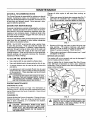
G E NE RATOR
MAINTE
Change oil while engine is still warm from running, se
follows:
......
=
Clean area around oil drain plug, remove plug (Fig. 7)
and drain oil completely into a suitable container.
When oil has drained, insta!l and tighten oil drain plug.
OIL DRAIN PLUG
\
NANCE
Generator maintenance consists of keeping the unit clean
and dry. Operate and store the unit in a clean dry environment where it will not be exposed to excessive dust, dirt,
moisture or any corrosive vapors. Cooling air slots in the
generator must not become clogged with snow, leaves or
any other foreign material.
Check the cleanliness of the generator frequenl]y and clean
when dust, dirt, oil, moisture or other foreign substances
are visible on its exterior surface.
NOTE: We DO NOT recommend\d using a garden hose
to clean the generator. Water can enter the engine fuel
system and cause problems, in addition, if water enters the
generator through cooling air slots, some of the water will
be retained in voids and cracks of the rotor and stator
winding insulation. Water and dirt build-up on the generator
internal windings will eventually decrease the insulation
resistance of these windings.
TO CLEAN
THE GENERATOR:
o
Use a damp cloth to wipe exterior surfaces clean.
O
Use a soft, bristle brush to loosen caked on dirt, oil, etc.
o
A vacuum cleaner may be used to pick up loose dirt
and debris.
FIG. 7
"
Remove oil fill plug and insert a clean fill funnel into
plug opening.
Fill engine crankcase with recommended oil until oil level is at point of overflowing.
About 21 ounces is required. POUR SLOWLY.
•
When engine crankcase is filled to proper level. Install
and tighten oil fill plug.
SERVICE AIR CLEANER
Your engine will not run properly and may be damaged if
you run it using a dirty air cleaner.
Clean or replace the air cleaner paper fil'0er(Fig. 8) once
every 100 hours of operation or once a year, whichever
comes first. Clean or replace more often if operating under
dusty or dirty conditions.
Low pressure air (not to exceed 25 psi) may be used
to blowavvay dirt. inspectcooling air slots and opening
on the generator. These openings must be dirt clean
and unobsl_ucted.
A
CAUTION: NEVER INSERTANY OBJECT OR TOOL
THROUGH THE AIR COOLING SLOTS, EVEN IF
THE ENGINE IS NOT RUNNING, DAMAGE TO THE
UNIT OR PERSONAL INJURY MAY RESULT.
ENGINE
COVE R
MAINTENANCE
CHECKING
OIL LEVEL
KNOB
See OPERATION section on Page 4 for information on
checking oit level. Oil level should be checked before each
use or at least every five hours of operation. Keep oil level
maintained.
CHANGING
OIL
Change oil after first 2 hours of operation. Change oil eve ry
50 hours thereafter. If you are using your generator under
dirty or dusty conditions, or in extremely hot weather,
change oil more often.
CAUTION:
DISCONNECT
SPARK
PLUG FROM
WIRE
FROM SPARK
PLUG AND KEEP
IT AWAY
SPARK PLUG. DO THIS EVERY TIME YOU PERFORM ANY MAINTENANCE ON THE ENGINE OR
THE GENERATOR.
FIG. 8
_'_
CAUTION: NEVER RUN THIS UNIT WlTHOUTTHE
COMPLETE AIR CLEANER SYSTEM INSTALLED
ON THE ENGINE. THIS COULD RESULT IN PREMATURE WEAR TO THE ENGINE.
MAINTENANCE
To clean or replace air cleaner:
•
Remove air cleaner cover; remove paper filter, ....
•
Clean air filter by tapping it gendy on s solid surface.
If the filter is too dirty, replace it with a new one,
Dispose of the oil filter properly.
•
Clean air cleaner cover then insert newpaper, filter into
cover and assemble to the base of the air cleaner.
REPLACE SPARK PLUG
•
:
Change the spark plug every 100 hours of operation or
once each ,lear, whichever comes first. This will help your
engine to start easier and run better. Replace wit_ Champion R C-J8 or equivalent type spark plug, Set spark plug
gap (Fig, 9) to 0.030 inch (0.76ram).
SERVICE
MAINTENANCE
OPERATION
FIG.9
RECOMMENDATIONS
25 Hours or Every
Season
Season
100 Hours or Every
Season
Check Oil Levee
Change Oil
X
Service Air Filter
Replace or Clean Spark Plug
Prepare Unit for S!_rage
X
Prepare unit for s_orage if!t
_ remain idle for mor e than 30 days.
NOTE 1: Change oil and oil filter after first 2 hours of operalJon and then ever,/50 hours 1hereafter.
operating under heavy load or in dusty or dirty environment or in high ambient temperature.
NOTE 2: Clean more often when operalJng the unit under dirty or dusty conditions.
8
Change
sooner when
......
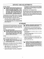
SERVICE
ENGINE
AND ADJUSTMENTS
o
SPEED
CAUTION:ATENGINE
SPEED WAS
JUSTED
THE FACTORY
ANDPROPERLY
SHOULD ADREQUIRE NO ADDITIONAL ADJUSTMENT. DO NOT
ATTEMPT TO CHANGE ENGINE SPEED. IF YOU
BELIEVE THE ENGINE ISRUNNING TOO FAST OR
TOO SLOW, TAKE YOUR GENERATOR TO
AUTHORIZED SERVICE (3ENTER FOR REPAIR
AND ADJUSTMENT. CHANGING ENGINE GOVERNED SPEED WILLVOIDrENG1NE WARRANTY.
ADJUSTING
High engine speeds are dangerous and increase the
risk of personal injury or damage to equipment,
•
Lowengine speeds impose a heavy load on the engine
when sufficient engine power is not available and may
shorten engine life.
THE CARBURETOR
The carburetor of your generator set is preset atthe factory.
DO NOT TAMPER WITH THE CARBURETOR as this will
void the warranty for the emission con_'ol system. If your
generator is to be used at an altitude above 5,000 feet,
consult with a Sears Authorized Service Facility regarding
high altitude jet_ng changes.
Your generator runs at a constant speed. This constant
operating speed is maintained by a mechanical, flyv_ight
type, fixed speed governor._ DO NOT try to adjust the
governed speed setlJngfor the following reasons:
•
The generator will supply correct rated AC frequenm¢
and voltage onlyatthe proper speed. Some connected
electrical devices could be damaged by incorrect freque ncy andior voltage.
STORAGE
The generator should be stared at least once every seven
days and allowad to run at least 30 minutes. If this cannot
be done and you must store the unit for more than 30days,
use me following information as a guide to prepare it for
storage.
STORAG
E INSTR
CAUTION:
SPRAYENGINE
FROM SLOWLY.
SPARK PLUG
HOLE WHEN AVOID
CRANKING
•
Install spark plug. Do not connect spark plug wire.
o
Clean dirt, oil and grease from cylinder, cylinder head,
fins, blower housing, rotating screen and muffler area.
GE NE RATOR
UCTIONS
=
WARNING:
NEVER STORE
WITHPOORLY
FUEL tN
THE TANK INDOORS
OR INENGINE
ENCLOSED,
VENTILATED AREAS, WHERE FUMES CAN
REACH AN OPEN FLAME SPARK OR PILOT LIGHT
AS ON A FURNACE, WATER HEATER, CLOTHES
DRYER OR OTHER GAS FURNACE,
Clean the generator as outlined on Page 7 (_Fo Clean
the Generator').
•
Check that cooling air slots and openings on generator
are open and unobstructed.
OTHER STORAGE TIPS
ENGINE
•
DO not store gasoline
•
e
Replace your gasoline
can if it starts to rust.
and/or dirt in your gasoline can cause problems
you use it with this unit.
o
Store in clean and dry area.
Run engine for about five minutes to warm it.
NOTE: lfyou did use "gasohol," drain fuel tank, then run
engine until engine stops from lack of fuel.
I
Ait
A
TAINER OUTDOORS, AWAY FROM OPEN FLAME.
WARNING:
DRAIN FUEL INTO APPROVED
CONBE SURE ENGINE
IS COOL.
NOTE: Using a fuel additive such as Sears Craftsman
Fuel Stabilizer, or an equivalent, will prevent gum deposits
from forming in _e generator's fiJel system.
While engine is still warm° drain oil from crankcase.
Refill with fresh oil. See BEFORE STARTING ENGINE on Page 5 for oil recommendations.
•
Remove spark plug and pour about I ounce (30ml) of
engine oil into cylinder, Crank slov_y to distIibute oil.
Rust
when
DANGER; STORAGE COVER IS FLAMMABLE. DO
NOT PLACE THE STORAGE COVER OVER A HOT
GENERATOR. LETTHE UNIT COOL FOR A SUFFICIENT TIME BEFORE PLACING THE COVER ON
THE UNIT. tF YOU PLACE THE COVER ON THE
UN1T BEFOREGENERATOR
ISCOOL,THE COVER
COULD START ON FIRE.
®
o
from one season to another.
9
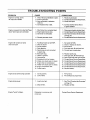
TROUBLESHOOTING
PROBLEM
Engine is running, but no
AC output is available,
POINTS
CAUSE
1.
CORRECTION
One of the circuit breakers is open.
2. Faultin generator.
3, Poor conneclion or defective
cord set.
4. Connected device is bad.
1, Reset circuit breaker.
2. Contact Sears Service Department.
3. Check and repair.
4. Connect another device that is
in good condition,
Engine runs good at no-load but'bogs
down" when loads are connected
Engine WIUnot start; or starts
and runs rouah.
Engine shuts down during operalion
Engine lacks power.
Engine "hunts"or falters.
1. Short circuit in a connected load.
2. Engine speed is too slow.
3. Generator is overloaded.
1. Disconnect shorted electrical load.
2. Contact Sears Service Department
3. See `Don_ Overload the Generator
4. Shored generator circuit
4_
1.
2.
3.
4.
5.
RuntStop Switoh setto STOP.
Dirty air cleaner
Out of gasoline.
Stale gasoline.
Spark plug wire not connected
6.
7.
8,
9.
to spark plug.
Bad spark plug.
Water in gasoline.
Overchoking.
Excessively rich fuel mixture.
on Page 10,
Contact Sears Service Depar_nent,
!. Setswitch to RUN.
2. Clean or replace air cleaner.
3, Fill fuel tank,
4. Drain gas tank; fill with fresh fuel.
5. Connect wire _ospark plug.
6.
7.
8.
9.
Replace spark plug.
Drain gas tank; fill with fresh fuel.
Open choke fully and crank engine.
Contact Sears Service Department.
10.
11.
12.
t3.
14.
intake valve stuck open or closed.
Engine has lost compression.
Intake valve stuck open or closed.
Engine compression lost
Failed batt_w,
!0. Contact Sears Service DeparVnent_
t !. Contact Sears Service Department_
t2. Contact Sears Service Department _
t3.
t4,
Contact Sears Service Department,
Replace battery.
1.
2.
Out0f gasoline.
Lowoil level.
1.
Fill fue! tank.
2.
Fill crankcase to proper level.
1. Load is too high.
1. See "Don't Overload _he Generator*
on Page 10.
2. Dirty air filter,
2. Replace air filter.
Carburetor is running too rich
or too leanl
]0
Contact Sears Service Department.
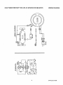
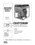
CRAFTSMAN
2500
WATT
DELUXE
AC
GENERATOR
580.327270
WIRING
DIAGRAM
=<
'{Z
C
{3
Z
n--
i
o
="
11
Drawing
No. 93438
CRAFTSMAN
2500
WAll"
A-C
GENERATOR
580. 327270
REPAIR
_P
o=
/
"7
p,,,
co
P_
_o
co
o'J
L
03
io
03
to
Drawing
No. 99373
12
PARTS
CRAFTSMAN
2500
ITEM
I
2
3
4
5
PART NO,
99369
95902 :
85652
143.53621
86292
6
75475
7
85651
8
t0
tl
t2
22129
38150
91824
66365-F
13
14
15
91820
65791
24420
16
19
66825B
86308D
20
2!
22264
66849
23
68759
24
25
26
77247
72092
91825
27
29
30
67451
51715
74908
3!
32
86494
84242
WATT
A-C
GENERATOR
580. 327270
DESCRIPTION
ENG|NE-SHP TECUMSEH (1 REQ.)
BASE, MOUNTING (1 REQ.)
VIBRATION MOUNT-ALT. (2 REQ.)
GROUND WIRE (t REQ.)
CAPSCREW,
SELF DRILLER #10
{1 REQJ
SCREW, PAN HD. MACH.
M4-0,7 x t0 (2 REQ.)
MOUNT, VIBRATION-ENGINE
(2 REQ.)
LOCK WASHER-M8 (6 REQ.}
WASHER, FLAT-#8 (2 REQ.)
STATOR ASSEMBLY (1 REQ.)
HOUSING, ENGINE ADAPTOR
(1 REQ.)
ROTOR ASSEMBLY (1 REQ.)
BEARING, BALL (1 REQ.)
BOLT, ROTOR-5/16"-24 x 6.25
(1 REQ.)
CARRIER, REAR BEARING (1 REQ.)
BOLT, STATOR M6-1.00 x 85MM
(4 REQ.)
LOCK WASHER-NO.8 (2 REQ.)
SCREW(TAPTITE)-MS-0.80
x 16ram
(2 REQ.)
RECEPTACLE-120VOLTS
AC, 20A
(1 REQ.)
BREAKER, CtRCUIT-20A (1 REQ.)
PANEL, RECEPTACLE (t REQ.)
BRUSH &BRIDGE RECTIFIER
( t R EQ.)
FLAT WASHER-[SPECIAL] (! REQ3
NUT, HEX, M4-0.7 (2 REQ.)
SCREW(TAPTITE)-M5-0.80
x l(_nm
(4REQJ
SCREW, M6-I.0 x 16 W1NG (1REQ.)
GROMMET RBC (2 REQJ
13
ITEM
33
PART NO.
86307
34
67022
35
36
45771
26850
37
38
22145
22769.
45
47
48
49
50
51
52
53
93639
93728
99377
98247
97082
81895
97178
97912
54
989568
55
98956A
56
57
58
98955
87841
39253
59
60
61
62
63
64
65
52858
22246
25391
49808
91094
75402
99368
66
67
96049
99541
REPAIR
PARTS
DESCRIPTION
CAPSCREW, HEX HD (4 REQ.)
5/16 -24 x 3/4 SEMS
GROMMET, BEARING CARRIER
(1 REQ:)
M8_1.25 HEX NUT (6 REQ.)
WASHER, SHAKE-PROOF M6-1/4
(2 REQ.)
FLAT WASHER-MS (4 REQ.)
WASHERi SHAKE PROOF #10
(1 REQ.)
DECAL, DANGER-ENGLISH
(1 REQ.)
AXLE, WHEEL 12REQ-)
DECAL, LOGO (1 REQ.)
DECAL, CONTROL PANEL (1 REQ.)
POSlTIONER, HANDLE (2 REQ.)
CAP PLUG, 3/4" SQUARE (4 REQ,)
KNOB, HANDLE (2 REQ.)
BOLT, CARRIAGE-t/4-20"
x 2-I/4"
(2 REQ.)
LEG & FOOT SUPPORT ASSEM,
LEFT SIDE (t REQ.)
LEG & FOOT SUPPORT ASSEM.
RIGHT SIDE (1 REQ.)
HANDLE (1 REQ.)
VIBRATION MOUNT-LEG (2 REQ.)
SCREW, HEX HD. CAPSC,
M8-1.25 x 20 LONG (6 REQ.)
NUT, FLANGE-MS-.1.25 (6 REQ.)
LOCKWASHE R-5/8" (2 REQ,)
NUT, JAM-5/8"- 18 (2 REQ,)
WASHER, FLAT-M12 (2 REQ.)
WHEEL, 8" DIA, (2 REQ.)
PUSH NUT-l/2" DtA. (2 REQ.)
PLATE, ANTI SCRATCH
AND WEAR (2 REQ.)
DECAL, 1-800NUMBER (1 REQ.)
DECAL, START INSTRUCTIONS
(1 REG.)
Drawing No. 99373
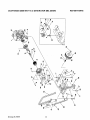
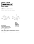
CRAFTSMAN
CRAFTSMAN
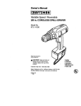
2500 WATT A-C G E NE RATOR
4-CYCLE ENGINE 143.965011
580.327270
REPAIR
161
/
'_30
287
Drawing No. 99625
14
PARTS
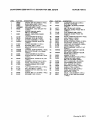
CRAFTSMAN
CRAFTSMAN
ITEM
1
2500 WATT A-C GENERATOR
4-CYCL E E NGINE 143.965015
PART NO.
36768
REPAIR
580.327270
DESCRIPTION
ITEM
Cylinder
(includes
2. 20, 72& 125)
11 req.]
Dowel Pin (2 req.)
Washer
11 req.)
Governor
Rod
Governor
Lever 11 reqo)
Governor
Laver Clamp 11 req.)
No+ 8-32 x 5116" Hex Screw 11 req+)
Extension
Spring (1 reqJ
Oil Seal (1 req.)
126
157
158
159
130
130A
135
160
151
163
154
155
PART
No.
Std. Intake Valve 11 req.|
O.S. Intake Valve (1 req.)
5116-18 x 1-1/2" Screw (7 req.)
5/18-!8
x 2-41t64"
Screw 11 req.)
34645
31672
31673
316649
650913
35624A
Spark Plug |RJ-17LM|
|1 req,|
Valve Spring (2 req,)
Lower Valve Spring Cap 12 req.)
Push Rod Guide 11 rsq,)
26727
28277
15
3O589
16
17
36618
36700
18
660548
19
3675O
2o
326oo
25
25A
26
36621
36622
3O200
Air Baffler 11 req,)
Air Baffle (1 reqJ
#10-24 x 9/16"Screw
30
35
36
34734A
29826
29918
37
29216
Crankshaft
(1 req.I
Screw, #10-32 x 3/4" 1t req.)
Look Washer
(1 req.)
Look Nut, #10-32
( 1 req.)
160
!61'
161A
173 _
3663(_
6510(_
651012
36675
38
40
29642
35544A
35545A
35546
Retaining
Ring |1
Piston Pin & Ring
Piston, Pin & Ring
Piston, Pin & Ring
Piston & Pin Assy.
Piston & Pin Assy.
Piston & Pin Assy.
178
192
184
165
200
203
204
650862
660451
26756
36631
36747
31342
206
207
610973
36632
209
215
650821
36638
223
224
238
650451
36581
28820
Oil Dipper (1 req.)
Camshaft
[BCR] (1 req.)
Blower Housing
Ext. |1 req.)
Screw,
It4"-20
x 5/8" 11 req.I
No+ 10-24 x 9116" Screw (1 req.)
239
240
245
250
251
27272A
36633
36046
36635
660686
Cylinder
252
650621
Cy_iner Cover Assy. (t req,)
Oil Drain Plug {2 req.)
Oil Seal 11 req,)
Governor
Shaft (1 reqJ
253
254
260
261
36701
36702
36812
- 651008
Flat Washer
(t req,}
Governor
Gear (1 req.,
261A
262
660621
651008
Governor
Spool I1 req.)
1/4-20 x 1-1t4" Screw (7 req .)
275
277
36641
651009
Flywhee|
Flywheel
Beileviite
2t_
287
290
35_
0
30705
292
300
26460
36812
41
35541
35542
35543
42
35547A
35546A
35549
43
45
20381
32875A
46
48
48
326t0A
35616
36611
50
60
36620
36623
64
650378
65
69
30200
36624
70
72
36761
27642
75
2846O
80
81
30574A
30593A
82
83
30591
36O57
86
65O488
89
90
610961
611205
92
93
lO0
650815
650816
34443A
t01
610118
102
103
110
651007
650814
36767
111
111A
112
1 t3
611207
611212
35967
650960
! 19
36738
120
125
36739
36471
36472
rsq.)
Sat (Std.)
Set {0.01 O,S.)
Set (0.02 O_S.)
{STD,)
(0.01 O.S.)
10.020.S).
Piston
Piston
Ring
Ring
Piston
Piston
Ring Set 10.02 O.S.)
Pin Retaining
Ring (1 req.)
Connecting
Connecting
Valve Lifter
Set {ST[:).)
Set 10.01 O.S.|
Rod Asey. 11 req.)
Rod Bolt (1 req.)
11 req.|
Cover
Gasket
{1 req.)
inct_ No. 81)
Key 11 req.)
11 req.)
Washer
(1 req.)
Flywheet
Nut {I req.)
Solid State Ignidon
11 req.|
DE SCRIPTION
293145
2_L315C
650912
2
14
(2 reqo)
PARTS
66(_14
36629
36626
Rocker
Arm Stud |2 req,)
Rocker
Arm (2 req,}
1/4"-28 Null2 req.)
Push Rod (2 req.)
Rocker Arm Cover Gasket
Rocker
1/4"-20
Stud .(2 req J
B_'eether
Tube
11 req,)
1/4"-20 Nut 12 req,)
I/4-20
x 1" Screw (2req.)
Carburetor
Gasket (1 req,I
Intake Pipe 11 req.)
Control
Bracket
A_sembly
Throttle
Link {1 req.)
#10-32
x 1/2" Screw
(2req.|
Control
5/16-18
Knob |1 req.)
x 1" Screw (2 req.)
Intake Pipe Gasket 11 req,)
#10-32
x 1/2" Screw 12 req.)
Air Cleaner
Gasket (1 req,}
Air Cleaner
Body (tncL 2391 [1 req.|
Air Cleaner
Filter 11 rsq.|
Air Cleaner
Cover (1 raq.)
Wing Nut 11 req.)
#10-32 X 112" Screw
(I req.)
Compression
Release
11 req,}
Compression
Release
Spring 11 req.|
Fuel Tank & Blower Housing
11 req.}
1f4;29
x 31tW
#10-32
1/4-20
Muffler
I/4-20
x 112" Screw (1 req,}
x 31164" Screw |2 teq.)
11 req.)
x 2-9132" Screw 12 req ,)
Screw
| 1 req ,}
Starter
Cup (I req.}
Rivet lean be purchased
Fuel
Fue!
Fuel
Ground
Wire _1 req.)
Lowell
Sensor
(1 req.)
Low Oil Indicator
Light I1 req.)
Low Oil Sensor
Gasket 11 req.)
Torx T-25 #10-24 x 5/8" Screw {4 req.)
325
341
370A
370B
370C
29443
36644
36261
33107
36260
Cylinder
Cylinder
Exhaust
Exhaust
37(]K
380
3_0
400
36695
640017
590736
36716A
Starter Decal (1 req.}
Carburetor
[incl. No.
416
36OB5
Spark ,A.tresting
Screen
[optional]
11 req.)
417
600
660760
•661013
15
11 req.)
Fuel Cap (1 req.|.
Oil Fill Plug (1 reqj
Spacer
11 req.)
Wire Clip 11 req.)
38246
27625
34080
{1 req,)
locally)
Line 11 req.)
Line Clamp (1 req.)
Tank & Blower Housing
301
311
313
Gasket {t req.|
11 req.)
[Std, incl, 151] (1 req,)
[I132" OS, incl. 151]
11 req.)
Compression
Spring 11 req.}
5-40x
7116" Screw 11 req.|
Terminal
Assembly
{1 req.)
Spark Plug Cover (1 req.|
Solid State Mounting
Stud 12 req.}
No. 10-24 x 1" Torx Screw (2 req.)
Head
Head
Valve
Valve
11 req,|
Arm Cover 11 reqJ
x 31/64" Screw {2 req.)
Fuel Tank Bracket 11 req.I
Lubrication
Decal (1 reqJ
Control
Decal 11 req.|
Primer Decal {1 req.|
Rewind
Gasket
1841 11 req.)
Starter
11 req.)
Set _1 req.)
#8-22 x 3/1B_ Screw
Washer
11 reqo)
andCover
[optional]
,,
{1 req.)
Drawing No. 99625
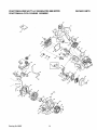
CRAFTSMAN
CRAFTSMAN
2500 WATT A-C GENERATOR
4-CYCLE ENGINE 143.965015
REPAIR
580.327270
/
13
_8
6__
_6
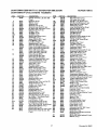
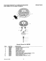
Re wind Starter No. 590736
ITE M
1
2
3
4
5
6
7
8
11
12
13
PART
NO.
590599A
5906O0
590696
590601
590697
590698
590699
590700
590687,
590535
590701
Drawing No. 99625
DESCRIPTION
_
PIN, SPRING [included No.,4] (1 REQ.)
WASHER (1 REQ.)
RETAINER (1 REQ.)
WASHER (1 REQ.)
..SPRING, BRAKE (1 REQ.)
DOG, STARTER (2 REQ.)
SPRING, DOG (2 REQ.)
PULLEYAND REWIND SPRING ASSEMBLY (1 REQ.)
HOUSING ASSEMBLY,_STARTER (1 REQ,)
ROPE, STARTER (1 REQ.)
HANDLE ASSEMBLY, STARTER (1 REQ.)
"
16
PARTS
CRAFTSMAN
2500
WATT
CRAFTSMAN
4-CYCLE
A-C
ENGINE
GENERATOR
REPAIR
580327270
PARTS
143.965015
20
I
1
-30
_
37
_
36
_37
44/_
40
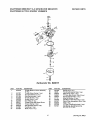
Carburetor
ITEM
1
2
4
5
6
7
16
17
18
20
25
27
PART NO.
631615
631767
631184
631183
631036
650506
632164
'650417
630766;
640O18
631867
631024
J_
No. 640017
DESCRIPTION
Throttle Shaft and Lever Assembly
(1 req.)
Thro_e Return Spring (1 reqJ
Dust Seal Washer (1 reqJ
Dust Seal [thtottJe} (1 req,)
Thm_e Shutter (1 req.)
Shutter Screw (1 req,)
Fuel Fitting (1 reqj
ThrotUe Crack/idle Speed Screw
TensionSpring (1 req.)
Idle Restricmr Screw (I req.)
FloatBov_ (t req.) '.
...... •
Shaft, Float (t req.)
17
ITEM
31
35
36
37
PART NO,
631022
36045
640019
632547
4O
640015
44
47
48 •
28
29
30
27110
630748
631027
632019
631028
631021
DESCRIPTION
Spring Clip (1 req.)
Primer Bulb/retainer Ring (1 req.)
Main Nozzle Tube (1 req.)
_O" Ring, Main Nozzle Tube (2 req.)
High Speed Bowl Nut {1 req.)
Bo_Nut Washer (1 req.)
Idle Mixture Wett Welch Ptug (1 req.}
Welch Plug, Atmospheric Vent (! req.)
Float (t req.)
' "0" Ring;'Float BOwt-!_-body {1 req.)
Inlet Needle, Seat & Spring Clip_
-Iincl:No,.31}_]
req.) '
"
Drawing No. 99625
FOR CALIFORNIA
CALIFORNIA
RESIDENTS ONLY WHEN SEEKING SERVICE
EMISSION
YOUR
WARRANTY
CONTROL WARRANTY
RIGHTS
AND
IN CALIFORNIA
STATEMENT
OBLIGATIONS
The Califomia Air Resources Board and Sears Roebuck and Co., USA (Sears), are pleased to explain the
emissions control system warranty on your 1995 and later lawn and garden equipment engine. In California new
utility and lawn and garden equipment engines must be designed, built, and equipped to meet the State's stringent
anti-smog standards. Sears must warrant the emission control system on your lawn and garden equipment
engine for the periods of time listed below provided there has been no abuse, neglect, or improper maintenance
of your lawn and garden equipment engine.
Your emission control system includes parts such as the carburetor and the ignition system.
Where a warrantable condition exists, Sears wilt repair your lawn and garden equipment engine at no cost to
you. Expenses covered under warranty include diagnosis, parts, and labor.
MANUFACTURER'S
WARRANTY
COVERAGE
The 1995 and later utility and lawn and garden equipment engines are warranted for two years, If any emission
related part on your engine (as listed below) is defective, the part will be repaired or replaced by Sears.
OWNER'S
WARRANTY
RESPONSiBILiTIES
As the lawn and garden equipment engine owner, you are responsible for the performance of the required
maintenance listed in your Owner's Manual. Sears recommends that you retain all receipts covering maintenance
on your lawn and garden equipment engine, but Sears cannot deny warranty solely for the lack of receipts or for
your failure to ensure the performance of all scheduled maintenance.
As the lawn and garden equipment engine owner, you should be aware that Sears may deny you warranty
coverage if your lawn and garden equipment engine or a part of it has failed due to abuse, neglect, improper
maintenance, unapproved modifications, or the use of parts not made or approved by the odginal equipment
manufacturer.
You are responsible for presenting your lawn and garden equipment engine to a Sears authorized repair center
as soon as a problem exists. Warranty repairs should be completed in a reasonable amount of time, not to exceed
30 days.
If you have any questions regarding your warranty rights and responsibilities, you should contact your nearest
authorized service center or catt Sears at 1-800-473-7247.
WARRANTY
COMMENCEMENT
DATE
The warranty period begins on the date the lawn and garden equipment engine isdelivered to the original, end-use
purchaser,
LENGTH
OF COVERAGE
Sears warrants to the initialowner and each subsequent purchaser that the engine is free from defects in materials
: and workmanship which cause the failure of a warranted part f_)ra period of two years.
•
I_8