1
MODEL NO.
536.797561
..................................
Caution:
Read and Follow
All Safety Rules
and Instructions
Before Operating
This Equipment
i
Part No 324779
lliH
lllllllllli,i,llll,lll
.............
_'L'Ul'lLl==
_
--
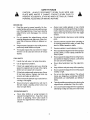
9 iNCH =3.0 HORSEPOWER
EDGER/TRIMMER
=
=
•
°
•
SEARS, ROEBUCK
i
Assembly
Operation
Customer Responsibilities
Service and Adjustments
Repair Parts
AND CO., Hoffman Estates, IL 60179 U.S.A.
_
,,,,,,, ,,, ,, ,,,,,,
ii
,,,llmll
SAFETY
CAUTION:
PLACE
ALWAYS
WIRE
WHERE
RULES
DISCONNECT
IT CANNOT
PREVENT
ACCIDENTAL
STARTING
PORTING,
ADJUSTING
OR MAKING
SPARK
CONTACT
WHEN
PLUG
WIRE
SPARK
SETTING-UP,
PLUG
AND
TO
'TRANS-
REPAIRS,.
BEFORE USE
e
Read the owner's manual carefully Be thoroughly familiar with the controls and the proper
use of the edgedtrimmer. Know how to stop the
edger/trimmer
and disengage the controls
quickly.
o
Always wear safety glasses or eye shields
during operation orwhile performing an adjustment or repairto protectyour eyes from foreign
objects that may be thrown from the edger/
trimrner_
e
Do not operate the edger!trimmer
without
wearing adequate outer garments. Wear footwear that wilt improve footing on slippery surfaces.
®
Do not put hands or feet near or under rotating
parts.
®
Exercise extreme caution when operating on
or crossing gravel drives, walks, or roads.. Stay
alert for hidden hazards or traffic.
•
Exercise cautiQn to avoid slipping or falling
®
Never operate the edgefltrimmer without proper
guards, plates, or other safety protective devices in place.,
•
Never operate the edger/trimmer at high transport speeds on sfippery surfaces. Look behind
and use care when backing.
®
Keep the area of operation clear of all persons,
particularly small children and pets_
=
Thoroughly inspect the area where the edger/
trimmer is to be used and remove all foreign
objects.
FU EL SAFETY
e
Handle fuel with care; it is highly flammable,.
®
Use an approved container.
e
e
Check fuel supply before each use, allowing
space for expansion as the heat of the engine
and/or sun can cause fuel to expand.
Never allow bystanders
mer,
®
Keep children and pets away while operating.
®
Never operate the edgerttnmmerwithout
visibility or light°
e
Do not run the engine indoors. The exhaust
fumes are dangerous (containing CARBON
MONOXIDE, an ODORLESS and DEADLY
e
Fill fuel tank outdoors with extreme care. Never
fill fuel tank indoors. Replace fuel tank cap
securely and wipe up spilled fuel,
®
®
Never remove the fuel tank cap or add fuel to a
running or hot engine.
Never store fuel or edger/trimmer with fuel in
the tank inside a building where fumes may
reach an open flame.
OPERATING SAFETY
Never allow children or young teenagers to
operate the edger/trimmer,
Keep them away
while it is operating. Never allow adults to
operate the edger/trimmer without proper ir_struction.
near the edger!trim-
good
GAS),.
®
Take all possible precautionswhen
leaving the
edgerttrimmer unattended. Stop the engine.
e
Do not overload the edgerttrimmer capacity by
attempting to edge too deep at too fast a rate.
SAFETY
RULES
SAFE STORAGE
o
Always refer to the owner's manual storage
section for important details if the edger/trimmer is to be stored for an extended period.
•
Never leave the edger/trimmer with fuel in the
fuel tank inside abuilding where ignition sources
are present such as water and space heaters,
clothes dryers, andthe like+.Allow the engine to
cool before placing in any enclosure_
®
®
Stop the blade whenever you leave the operating position. Also, stop the engine and disconnect the spark plug wire before unclogging the
blade and when making any repairs, adjustments, or inspections.
e
When cleaning, repairing, or inspecting, shutoff the engine and make certain all moving
parts have stopped+
a
Never attempt to make any adjustments while
the engine is running (except when specifically
recommended by the manufacturer)..
Keep the edger/trimmer in safe working condition+ Check all fasteners at frequent intervals
for proper tightness,.
REPAIRIADJUSTMENTS
SAFETY
®
After striking a foreign object, stop the engine
(motor). Remove the wire from the spark plug,
and keep the wire away from the plug to
prevent accidental starting. Thoroughly inspect
the edger/trimmer for any damage, and repair
the damage before restarting and operating
the edgedtrimmer..
®
If the edger/trimmer
should start to vibrate
abnormally, stop the engine (motor) and check
immediately for the cause+ Vibration is generally a warning of troubieo
i
A
,_j_
iii
ii i i iiil.+
i
i
iiii
iii
iii
i ii,lml,,ll,ull
i
I
LOOK FOR THIS SYMBOL TO POINT OUT
IMPORTANT SAFETY PRECAUTIONS.
IT I
MEANS--ATTENTION!!! BECOME ALERT!!!_
i
3
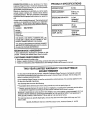
PRODUCT SPECIFICATIONS
CONGRATULATIONS on your purchase of a Sears
Craftsman Edger/Trimmer. It has been designed, engineered and manufactured to give you the best possible
dependability and performance.
Should you experience any problem you cannot easity
remedy, please contact your' nearest Sears Service
CentedDepartment. We have competent, well-trained
technicians and the proper tools to service or repair this
unit.
....
/
i1'
I
filL"
.........
"
.............
HORSEPOWER:
3.0 hp
DISPLACEMENT:
9.06 cu. in.
(148 c.c)
GASOLINE
Please read and reta{nthis manual. The instructions will
enable you to assemble and maintain your edger/trimmer properly. Always observe the.,SAFETY RUL.ES."
MODEL
NUMBER
i
CAPACITY:
1.0 qt.
Unleaded
(Regular)
LUBRICATION:
21 oz.
SAE 30
536.797561
SERIAL
NUMBER
DATE OF
PURCHASE
SPARK
(GAP
,
PLUG :............. ....... Champion
.030 in.)
CJ-8 or
Equivalent
THE MODEL AND SERIAL NUMBERS WILL BE
FOUND ON A DECAL ON THE FRAME OF THE
EDGER/TRIMMER BEHIND THE ENGtNE_
YOU SHOULD RECORD BOTH SERIAL NUMBER
AND DATE OF PURCHASE AND KEEP IN A SAFE
PLACE FOR FUTURE REFERENCE°
MAINTENANCE
AGREEMENT
A Sears Maintenance Agreement is available on this
product,,Contact your nearest Sears Store for=details.
CUSTOMER
RESPONSIBILITIES
e Read and observe the safety njleso
e Follow a regular schedule in maintaining, caring for and using your edger/trimmer,
e Follow the instructions under"Maintenance" and "Storage" sections of this owner's manual
_::
I/I
,,,
iiI
It
....................
iiiiiiiiiii/
/
.........
11111
TWO YEAR LIMITED WARRANTY ON CRAFTSMAN
EDGER/TRIMMER
For two years from the date of purchase, when this Craftsman Edger/Trimmer is maintained, lubricated
and tuned-up according to the instructionsin the owner's manual, Sears willrepair, free of charge, any
defect in material and workmanship.
Ifthis Craftsman Edger/[rimmer is used for commercial or rental purposes, this warranty applies for only
90 days from the date of purchase.
This warranty does not cover the following:
® Expendable items which become worn during normal use, such as spark plugs, etc=
e Repairs necessary because of operator abuse or negligence, including bent crankshafts and the faifure
to maintain the equipment according to the instructionscontained in the owner's manual
WARRANTY SERVICE IS AVAILABLE BY RETURNING THE CRAFTSMAN EDGER/TRIMMER TO THE
NEAREST SEARS SERVICE CENTER/DEPARTMENT IN THE UNITED STATES THIS WARRANTY
APPLIES ONLY WHILE THIS PRODUCT IS IN USE IN THE UNITED STATES.
This warranty gives you specific legal rights, and you may also have other rights which may vary from
state to state..
SEARS, ROEBUCK AND CO. D/817WA, Sears Tower, Hoffman Estates, tL 60179
4
""
,_,_,,,,,,,,,
_,,_,_,,_,
,i j
i
,i
,
i,u
,_=,,=,,L_,=_,=
SAFETY
a_gCES
U,lU
TABLE O
............................................
...................
i
ii
,,
.................
lUlUU
CONTE ....TS
TROUBLE
SHOOTING
..................................... 16
STORAGE ................................................................ 17
REPAIR PARTS
2_3
PRODUCT
SPECIFICATIONS
..............................4
CUSTOMER
RESPONSIBILITIES
......4, 12-13
WARRANTY .............................................................
4
TABLE
(EDGER/TRIMMER)
........................................18-20
REPAIR PARTS (ENGINE) ...................... 21-23
PARTS ORDERING/SERVICE
.........
Back Cover
...................................................................
5-7
OF CONTENTS
ASSEMBLY
OPERATION
SERVICE
...................................... 5
................................................. 8-11
AND ADJUSTMENTS
...............14-'t 5
............
......................
i ii
BLY
..............................
CONTENTS
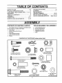
OF SHIPPING
CARTON
TOOLS
22211-
1 - 9inchEdgerfrrimmercompletefyassembledexcept
for the control rod, handles and wheels
1 - Control Rod
1 - Owner's Manual (Not Shown)
1 - Parts Bag
1 - Upper Handle Assembly
i - Lower Handle Assembly
3- Wheels
CONTENTS
i
OF PARTS
REQUIRED
u
,u,l,l,lu
ii
lUll
....................
FOR ASSEMBLY
1/2 inch Wrenches and
9/t6 inch Wrenches or
Adjustable Wrenches
Flatblade Screwdriver
Knife
BAG (shown
actual
2 - Hair Pins
2 - 5116-18 x 1-114 inch
Hex Head Screws
i
lU
size)
6 - 5/16-18 Hex Nuts
© i........
ill
...........
4 - 5/16-18 x 5f8 inch Hex
Head Wide Flange Screws
1 - 1.05 inch long Spacer
(front wheel assembly)
1 - 3t8-16 Hex Head
Wide Flange Locknuls
@
t'1
li
1 - 5t16-18 x 3-114 inch
Hex Head Screw
1 - ,70 inch long Spacer
(left rear wheel assembly)
@ 11 -I
1 - 1.39 tnch long Spacer
(front wheel assembly)
I - 3/8-16 x 1,,40 inch
Shoulder Boll
1 - Cotter Pin
@
1.5/16-18
Wide Range Locknut
2 - 11/32 x 11/16 Inch
Flatwashers
(front wheet assembly)
I - 1/2 x 3/4 inch Flatwasher
(right rear wheel assembly)
u, uu
5
i ul
_.,..,JJ
i
i
.................
::
HIIIIIIIIIIII
III
II
II I'll
I
I
_
I
. I:
............................
'1
'
---.
ASS
1'
III
'
III
II
I'I"
:::
I
III
L
..........................
IIILIIIlll
I
:
...........
:
...........
...........
::
I rl"/'
.....
..........
:
IIII
I LI
LY
"
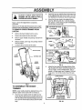
CAUTION: ALWAYS WEAR SAFETY
GLASSES OR EYE SHIELDS WHILE
ASSEMBLING EDGER!TRIMMER.
::
"
:
III
IIIIIIIIIII
IIII
" .......................
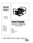
Q
Attach the right rear wheel to the wheel support rod
of the edger/trimmer (See Fig 2A) with a 1/2 x 3/4
inch flatwasher and cotter pin (found in parts bag)..
o
Attach the left rear wheel to the edger/trimmer
(See Fig, 2B) with a 3/8-16 x 1A0 inch shoulder
bolt, spacer (_70 inch long) and 3/8-16 wide flange
Iocknut (found in parts bag).
:
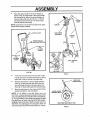
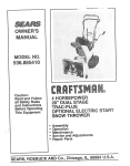
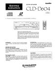
Figure I shows the edger/trimmer completely
assembled
Reference to the right and left hand side of the edger/
trimmer is from the operator's positionbehind the unit..
TO REMOVE EDGER/TRIMMER
FROM
(_)
(VIEW FROM RIGHT SIDE)
FLATWASHER
COTTER
PIN
CARTON
®
Remove the lower'handle from the carton.
e
Remove the control rod from the carton
®
Remove upper handle and packing material from
the carton.
WHEEL
WHEEL SUPPC)RT ROD
(_) (VIEW FROM
Remove wheels, parts bag and packing material
from tile carton
WHEEL _
SHOULDER
Cut down all fourcorners of the carton_
IJLIIIII I I I
IIIII
WIDE FLANGE
...........................
SPACER
LOCi(NUT
Io7O
INCHLONG)
CLUTCH LEVER
_
(VIEW FROM
SPACER
(1,39 INCH LONG)
UPPER
HANDLE
'_......,
CONTROL ROD
5f16-18 HEX
WIDE FLANGI
LOCKNUT
SCREW
WHEEL"
LOWER
HANDLE
STARTER
HANDLE
FLATWASHER
ACER
(!,,05 !NCH LONG
FIG. 2
O
BLADE
GUARD
Attach the front wheel to the edger/trimmer (See
Fig.,2C) with a 5/16-18 x 3-1/2 inch hex head screw,
two (2) 11/32 X 11/16 inch flatwashers, one (t)
spacer (1.05 inch long), one (t) spacer (139 inch
long) and a 5/16-18 hex locknut (found in parts
bag): ......................................
LOWER HANDLE
5116-18
HEX HEAD
LOCKNUTS
5f16-18
HF-.XHEAD
LOCKNUTS
BLADE
FIG. 1
TO ASSEMBLE
THE EDGER/
TRIMMER
NOTE: Lower handle should be attached first as it is
difficult to attach lower handle with the wheels on
®
Place the lower handle inside the edger/trimmer
frame (See Fig_3A) and secure inplace with four(4)
5/16-!8 x 5/8 inch hex head wide flange screws and
four (4) 5/16-18 hex head iocknuts (found in parts
bag)..
5/16-18 X 5f8 INCH
HEX HEAD WIDE
FLANGE SCREWS
IIII
I
iii I,
FIG, 3A
6
...........
T_
Illlllll
I
I'11'
II1!]
!
ffll'lJ
I
I
'1
I
'1'11'
I
I
,,,i
ASSI I li LY
e
Place the upper handle on the lower handle as
shown in Fig. 3B. A1ign hotes in the upper handle
with the top set of holes in the lower handle and
secure in place with two (2) 5/16-18 x t-1/2 inch
hex head screws and two (2) 5/16-18 hex head
Iocknuts (found in parts bag)
CLUTCH
LEVER
NOTE: Clutch lever is on the left hand side of the upper
handle when properly instatted_
HAIR PIN
LEVER
FIRST DEPTH
SELECTION
CONTROL
ROD
HAIR PIN
QUILL
SUPPORT
ARM
QUILL
SUPPORT
ARM
SPACER
Fig. 4 inset
FIG, 3B
FIG. 4
•
Insert one end of the control rod from left to right
through the hole in the clutch fever(See Fig 4) and
attach with a hair pin (found in the parts bag)
o
Place the clutch lever in the first depth selection
(See Fig. 4) and insertthe other end oi the control rod through the hole in the quill support arm
(See Fig. 4) Attach with hairpin (found in parts bag)
•
Move the clutch lever to the rearmost (NEUTRAL)
position and latch in See note below
LOWER HANDLE
MOUNTING BOLTS
NOTE: if it is difficult to get the clutch lever into
NEUTRAL, it may be necessary to loosen the four screws
and nuts holding the lower handle to the frame (See Fig
5).. Pry up (forward) on the handle only enough to allow
the clutch lever to freely enter the NEUTRAL position..
Retighten nuts and screws. When the clutch lever is in
NEUTRAL the Quill Support Arm should be within 1/4
inch of the spacer and screw behind it (See Fig 4 inset)
VIEW FROM RIGHT SIDE OF UNIT
FIG, 5
7
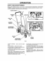
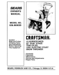
KNOW YOUR EDGER/TRIMMER
READ THIS OWNER'S
MANUAL AND SAFETY
RULES BEFORE OPERATING
YOUR EDGER/
TRIMMER,
Compare the iUustrationswith your edgerttrimmer to familiarize yourself witt_the locationof various
controlsand adjustments,. Save this manual for future reference
CLUTCH LEVER
MUFFLER
ROD
INDEX LEVER
FUEL FILL
CAP
BLADE
THROTTLE CONTR(
STARTER
REAR
WHE!
REAR VIEW OF ENGINE
OIL FILL
CAP
BLADE
GUARD
ADJUSTABLE
FRONT WHEEL
FIG, 6
THROTTLE CONTROL - Used to control the engine
speed,
BLADE GUARD - Used to prevent stones or other material from being thrown at the operator.
CHOKE CONTROL - Used to start the engine
ADJUSTABLE FRONT WHEEL - Front wheel is adjustable from side-to-side for balance.. Also, can be adjusted
down for curb-hopping (to level edgedtrimmer when
edging along a curb),.
STARTER HANDLE - The engine on this edger/trimmer
is equipped with an easy pull recoi1starter
CLUTCH LEVER - Used to start and stop the blade and
control the depth of cut.
INDEX LEVER - Permits adjustment from the edging
(vertical) position to trimming (horizontal) position To
change position, pull the index lever and rotate the quill
assembly to the desired angle or position
ADJUSTABLE REAR WHEEL - Right rear wheel is
adjustable for curb-hopping (to level edger/trimmer when
edging along a curb)..
..........................
.
i
iiiiii i
iiii
OPE
i
,
i
1,171
.........
0
.........................
.
i
.......".':'T".
"'
,.,,,
_ ,,_L
The operation o! this edger/trimmer Canresult in foreignobjects being thrown into the
eyes, which can result in severe eye damager Always wear safety glasses or eye
shields while operating the edger/trimmer,
We recommend standard safety glasses or Wide Vision Safety Mask for over your
glasses
CAUTION: KEEP AWAY FROM THE ROTATING BLADE. THE BLADE CAN CAUSE
INJURY.
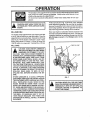
FILL/ADD OIL:
The engine on this edger/trimmer was shipped with little
or no oil. Add oil before you start the engine. Place the
edger/trimmer on a level surface. Remove the oil fill cap
(See Fig 8). Fill the engine crankcase to point of overflowing using about 21 ounces (1-1/4 pts) of Sears SAE
10W-30 motor oil or equivalent Reinstall the oil fill cap..
Fill the fuel tank (See Fig_7) with clean, fresh, unleaded
grade automotive gasoline. Be sure that the container
you pour the gasoline from is clean and free from dust or
other foreign particles Never use gasoline that may be
stale from long pedods of storage in the container
Never use engine or carburetor cleaner products in the
fuel tank or permanent damage may occur You may use
a gasoline stabilizer for extended storage (see the Engine Storage paragraph in the Storage section of this
manual).
J
UI
J
L
FUEL
FILL GAS:
AND CAUTION MUST BE USED WHEN
CAUTION: GASOLINE IS FLAMMABLE
HANDLING OR STORING IT. DO NOT
FILL FUEL "I'ANK WHILE EDGER/TRIMMER IS
RUNN1NG_HOT, OR WHEN EDGER/TRIMMER IS
tN AN ENCLOSED AREA. KEEP AWAY FROM
OPEN FLAME, ELECTRICAL SPARK, AND DO
NOT SMOKE WHILE FILLING THE FUEL TANK.
NEVER FILL FUEL TANK COMPLETELY; BUT
FILL THE TANK TO WITHIN 1/4 -1/2 INCH FROM
THETOPTO PROVIDE SPACE FOR EXPANSION
OF FUEL° ALWAYS FILL FUELTANK OUTDOORS
AND USE A FUNNEL OR SPOUT TO PREVENT
SPtLLING_ MAKE SURE TO WIPE UP ANY
SPILLED FUEL BEFORE STARTING THE ENGINE.
STORE GASOLINE IN A CLEAN, APPROVED
CONTAINER_ AND KEEP THE CAP IN PLACE ON
THE CONTAINER. KEEP GASOLINE IN A COOL,
WELL VENTILATED PLACE; NEVER IN THE
HOUSE. NEVER BUY MORE THAN A 30 DAY
SUPPLY OF GASOLINE 70 ASSURE VOLATILITY°GASOLINE IS INTENDED TO BE USED AS A
FUEL FOR INTERNAL COMBUSTION ENGINES;
THEREFORE, DO NOT USE GASOLINE FOR ANY
OTHER PURPOSE. SINCE MANY CHILDREN LIKE
THE SMELL OF GASOLINE, KEEP IT OUT OF
THEIR REACH BECAUSE THE FUMES ARE
DANGEROUS TO INHALE, AS WELL AS BEING
EXPLOSIVE.
........................................
i
,,
FILL CAP
OIL FILL CAP
FIG. 7
|
WHILE'THE
ENGINEFILL
IS RUNNING
ORTANK
HOT. I
CAUTION: NEVER
THE GAS
IMMEDIATELY WIPE OFF ANY SPILLED I
GASOLINE BEFORE ATTEMPTING TO
START THE ENGINE_
I
Ill
I
L'_I
_
/
II
I
I IIIIIIlU"I
I
I
I
I
II
O
........................
CHECK
Ill'
illll,,,,,meul
e
•
_lln'
i,iiiii
"".
OF CONTROLS
.......................
o
All controls should be checked for proper function before
servicing or starting the engine
e
H
RAT
i
PRE-USE
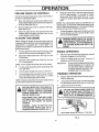
IIII
Move the clutch lever to all six (6) positions in the
selector plate, Make surethe clutch leversnaps into
all six (6) holes (See Fig 6).
NOTE: The cutting blade speed is controlled by the
engine speed.. To reducethe cutting blade speed, push
down on the throttle control lever.. To increase the blade
speed, push up on the throttle control lever..
Move the index lever to afi six notches in the index
plate (See Fig..6)..
Return the clutch lever to the rearmost hole in the
selector plate and return the index lever' to the
vertical (deeper notch) position
To stop the engine, make sure the clutch lever is all
the way back (or' up) and move the throttle control
lever to the STOP position.
•
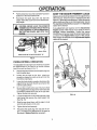
TO START THE ENGINE
i
Pull the clutch lever all the way back (or up) to the
rearmost hole to raise and disengage the blade.
o
Move the throttle control lever (See Fig. 6) to the
RUN position..
o
Move the choke control lever (See Fig 6) to the
FULL choke postion.
.....
To start engine, grasp the starter handle firmlywith
your right hand.
e
Hold the upper handle firmly with your left hand
e
PulIup sharply onthe recoil starter handie DONOT
allow the starter rope to snap back, let it rewind
slowly while holding the starter handle.
m
:
EDGING
:
I I
II IIII
IIII u
ii II
OPERATION
e
Start the engine and move the clutch lever forward
(or down) to engage the cutting blade
e
Select the edging depth you need There are 5
selections up to 2-3/4 inches deep
IMPORTANT:
NOTE: A warm engine should not need to be choked
•
• _1 ll,ll=,ll=
CAUTION: NEVER LEAVE THE EDGER/
TRIMMER UNATTENDED WHILE _,HE ENGINE IS RUNNING. ALWAYS DISENGAGE
THE CUTTING BLADE AND STOP THE
ENGINE,
Before starting the engine, be sure you have read and
understood allthe instructionson thepreceding pages The
edger/trimmer is equipped with a recoil starter. The
operation of the engine is controlled by the throttle and
choke control levels
o
When the engine starts, move the choke control to
the OFF speed position To increase the engine
speed, push the throttle control lever' up. To decrease the engine speed pull the throttle control
down
TRIMMING
IFVERY DEEP EDGINGIS REQUIRED,
WE RECOMMEND THATA SHALLOW
CUT BE MADE FIRST, THEN CUTS
AT GREATER DEPTHS UNTIL THE
DESIRED DEPTH IS OBTAINED..
OPERATION
Stop the engine and disconnect the spark plug wire
from the spark plug
NOTE: It will take a few pulls on the starter handle to feed
gas from the fuel tank to the carburetor
Loosen the tee knob (See Fig, 8) on the front wheel
arm and slide the wheel all the way to the rightside
e
CAUTION: NEVER RUN THE ENGINE INDOORS OR IN A POORLY VENTILATED
AREA. ENGINE EXHAUST CONTAINS
CARBON MONOXIDE, AN ODORLESS
GAS AND DEADLY GAS.
Tighten the tee knob securely.,
CAUTION: THE FRONT WHEEL MUST BE
IN TIlE EXTREME RIGHT POSITION TO
PREVENT THE BLADE FROM STRIKING
WHEEL WHILE IN TRIMMING POSITION.
KEEP HANDS, FEET, HAIR AND LOOSE
CLOTHING AWAY FROM ANY MOVING
PARTS ON THE ENGINE OR EDGER!
TRIMMER.
WARNING - AVOID THE MUFFLER AND
SURROUNDING AREAS (SEE FIGo 6),
TEMPERATURES MAY EXCEED 150° F.
TEE KNOB
FRONT WHEEL SHOWN ALL THE WAY TO THE RIGHT
FIG. 8
t0
OPERATION
Li
®
J
ill i
ii
ii,l,ll IlL
....
.......
CAUTION: NEVER LEAVE THE EDGER/!
TRIMMER UNATTENDED WHILE THE ENGINEIS RLINNING.ALWAYSDISENGAGE
THE CUTTING BLADE AND STOP THE
ENGINE ...........
LEVER
IN THE
NOI'CH
MARKED
CLEAN
section of this manual.
If any adjustments are required, see the Adjustments/
Repairs section of this manual_ If any parts are worn or
damaged, replace immediately_ Contact the nearest
SEARS Store or Service Center for proper original parts,
as shown in the Repairs Parts section of this manual
Make repairs as instructed in the AdjustmentstRepatrs
section of this manual
i
!
!
I
\
INDEX LEVER
INDEX
'_.................
Always remove thedirt and debris from the edger!trimmer
after each use,,Check for loose or damaged parts after
eachuse Tightenanyloosefasteners Checkthecontrols
often to make sure they are functioningproperly See the
Pre-Use Check of Controls paragraph In the Operation
Reconnect the spark plug wire and start the
engine, Move the clutch lever to the desired trimming height
A
_,
u_==
Ill I I"""l,lll_J
'
KEEP THE EDGER/TRIMMER
Pulithe index lever out of its notch (See Fig 9) and
position it in the notchmarked "90"
o
_
"90"
FIG. 9
CURB-HOPPING
OPERATION
The adjustable front and right rear wheel feature permit
the edger/trimmer to be used on an uneven surface
(such as a curb) as shown in Fig 10
®
Stop the engine and disconnect the spark plug wire
from the spark plug
o
Loosen the tee knob on the front wheel arm
enough to release the notch on the arm from the
front of the main frame..
®
Lower the front wheel to a position that places the
edger!trimmer level with the left rear wheel on the
uneven (curb) surface
g
Be sure that a notch on the rear of the front wheel
arm engages the front edge of the main frame and
the wheel is pushed all the way to the right side
Tighten the tee knob securely
®
Loosen the tee knob on the inside right rear of the
main frame that secures the wheel support rod
(See Fig. 10)
e
Slide the rear wheel down until the edger is level
when the left wheel is on the curb
o
Tighten the tee knob securely.
Q
Reconnect the spark plug wire and start the engine The depth of cut adiustment is the same as
described in Edging Operation paragraph
TEE
KNOB
BLADE
GUARD
WHEEL
SUPPORT
ROD
TEE
KNOB
FRONT
WHEEL
ARM
\
FIG. 10
1!
..........
CUSTOMER
..............
:
RESPONSIBILITIES
..................
JL,,
llll,
i,
iu llllll
,,,,ui
ii
,,,,,,,,,,,ill
i
......
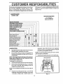
in thismanual, The followingMaintenance Check List is
supplied to assist the operator properly maintain the
edgerttrimmer
The warranty on this edger/trimmer does not cover items
that have been subjected to operator abuse or negligence. To receive full value from the warranty, the
operator must maintain the edger/trimmer as instructed
MAINTENANCE
CHECK LIST
SERVICE
RECORD
FILL IN DATES
AS YOU COMPLETE
REGULARSERVICE
BEFORE STORAGE
BEGINNING EACH SEASON
:_-VERY25 HOU RS OF-USE
i EVERY 10 HOURS OF USE
EVERY 5 HOURS OF USE
FREQUENTLY
BEFORE EACH USE
AFTER FIRST 2 HOURS OF USE
Check Engine Oil Level
Change Engine Oil
Tighten All Screws and Nuts
Check Blade Wear/Damage
®
®
®
,,,,_
®
®
® O
®
®
Replace Air Cleaner Filter
Check Spark Plug
_
!® ............
Lubricate all Pivot Points
.......
l_uSricat_:Wh_l
Q
_les
,,,,,,,, ,,,,
.....
i
®
®i
i®
, ,,,,
,, ....
equivalent Sears SAE 30 motor oil or equivalent
may be used as an acceptable substitute Reinstall
the oil _l cap and tighten securety.
LUBRICATION
®
Apply light machine oil after each 25 hours of use to
all moving parts, particularly the wheels.
e
The oilin the crankcase must be changed after the
first 2 hoursof operation and after each 25 hours of
use thereafter.
NOTE: The quill assembly bearings are factory sealed
and will require no lubrication.
o
NOTE: If the edger/trimmer is being used in sandy or
dusty areas, change the oil more frequently to prevent premature engine wear,
VIEW
To change the crankcase oil:
e
Disconnect the spark plug wire from the spark plug
®
Remove the oil drain plug (See Fig. 11) and drain
the oil into a flat pan After drafffing all the oil,
reinstall the oil drain securely.
Reconnect the spark plug wire on the spark plug.
NOTE: The oil will drain more freely when the engine is
warm.
Remove the oil fill cap (See Fig. 6), and fil! the
crankcase to the point of overflowing, using about
1-1/4 pints of Sears SAE 10-W30 motor oil or
12
FROM
REAR
CUSTOM
a
ESPON
:::
ii
ii
LiT!
,11, ,111
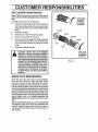
AIR CLEANER MAINTENANCE
i
i
.....
"......................................
Replace the filter once a year; more often under dusty or
dirty cond_ionso DO NOT attempt to clean or oil the air
filter.
Disconnect the spark plugwire from the spark plug,
o
Turn the cover (See Fig,,9) tothe left (counterclockwise) and re move the cover and the air filter from the
flange.
Discard the air litter,
o
@
@
RETAINER
Push the cover firmly against the flange and turn it
to the right (clockwise) as far as it will go (See Fig.,
12)., Be sure the retainers are locked around the
flange,
COVER
SLOT
TAB
CAUTION: NEVER RUN THE ENGINE
WITHOUT THE AIR CLEANER ELEMENT
INSTALLED. A DEFECTIVE AIR CLEANER
CAN RESULT IN LOSS OF ENGINE POWER
AND CAN CAUSE EXCESSIVE WEAR OR
DAMAGE TO THE ENGINE COMPONENTS
IF DIRT OR DUST IS PERMITTED TO ENTER THE ENGINE THROUGH THE CARBURETOR. A DAMAGED AIR CLEANER,
OR ONE THAT IS CLOGGED WITH DUST
OR DIRT SHOULD BE REPLACED IMMEDIATELY,
ii ii
............
.....
FILTER
Clean the cover and the flange thoroughly.
Insert the new air filter into the cover.
i ii ill
i
FLANGE
Reconnect the spark plug wire,,
::::_
......
ii
TURN COVER
TO THE LEFT
(COUNTERCLOCKWISE)
TO REMOVE
To install a new air filter, do the following:
e
iii1,11111111
ii i i mill
TURN COVER
TO THE RIGHT
(CLOCKWIS_
TO INSTALL
FIG. 12
.
SPARK PLUG MAINTENANCE
Clean the spark plug and reset the gap periodically,,
Clean the area around the spark plug base, before
removal, to prevent dirt from entering into the engine.
Replace the spad_ plug if the electrodes are pitted or
burned or if the porcelain is cracked_ Clean the spark plug
by carefully scraping the electrodes (do not sand blast or
use a wire brush). Be sure the spark plug is clean and lree
ot foreign material. Check the electrodes gap with a wire
feeler gauge and reset to ,035i1 necessary,, If a newspark
plug is needed, refer to the Engine Operation and
Maintenance manual for the properreplacement spark
plugo
Before reinstallingthe spark plug,coatthe threads lightly
with graphite or light oil to insure easy instatlation and
removal. Tighten the spark plug firmly intothe engine. If
a torque wrench is available, torque the spark plugto 15
foot- pounds,
13
i LI
SE
.....
_
CE
i
i
iiiill
ADJUST
CAUTi0N:i_c)
NOT ATTEMPT
TO
SHARPEN THIS BLADE. YOU COULD
CAUSE DAMAGE TO THE BLADE WH ICH
COULD RESULT IN BREAKAGE AND
POSSIBLE USER OR BYSTANDER
INJURY,
CAUTION: ALWAYS STOP THE ENGINE
AND DISCONNECT THE SPARK PLUG
WIRE BEFORE MAKING ANY REPAIRS
TO THE EDGER/TRIMMERo
V-BELT
TS
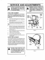
REPLACEMENT
Your edger/trimmer is equipped with a V-belt made of a
special compound. If the belt becomes worn or breaks,
replace it with an original equipment belt as shown in
the Repair Parts section of this manual NEVER USE A
SUBSTITUTE.
®
Disconnect the spark plug wirefrom the spark plug
e
Pull the clutch lever back (or up) to release the
tension from the belt
e
Remove the two top screws from the engine pulley
cover (See Fig !0) and remove the cover.
ENGINE
PULLEY
COVER
ENGINE
PULLEY
COVER
SCREWS
SPACER
ENGINE
PULLEY
NOTE: Make sure you do not lose the spacer on the rear
screw,
e
Remove the front screw securing the belt guide
(See Fig t0) to the engine Then loosen the rear
screw and swing the belt guide away from the belt
e
Remove the three (3) screws from the front belt
guard (See Fig 11)..
e
Remove the belt from the engine and quill assembly
pulleys and install the new belt,
®
lnstal! and secure front belt guard
e
Secure the belt guide loosened earlier-
e
Reinst allthe engine pu Iley cover and reconnect the
spark plug wire
BLADE
FRONT
SCREW
V-BELT
BELT
GUIDE
FIG. 10
REPLACEMENT
The cutting blade is subject to wear and damage such as
nicks anddents This willnot generally affect itsfunction
This blade is specially designed to not require sharpening,,DO NOT ATTEMPT TO SHARPEN THiS BLADE
The blade is reversible. If the nicks and dents are
excessive, remove the blade, turn itaround and reinstall
This will provide a fresh cutting edge Ifwomordamaged
the blade should be replaced
BELT J
GUARD
BELT
GUARD
SCREWS
CAUTION:
WHEN REMOVING
OR
TIGHTENING THE BLADE NUT, ALWAYS
USE THE METHOD SHOWN IN FIGURE
12oTHE HOLDING WRENCH MUST ALWAYS BE POSITIONED ON THE NUT
BEHIND THE CUTTING BLADE_
FIG. 11
14
REAR
SCREW
SERVICE AN .....ADJUST
...................
,_
:
.
ii
iin
III
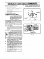
To replace the blade, do the following:
e
Disconnect the spark plug wire
e
Remove the hex Iocknut and flatwasher (See Fig
12) securing the blade to the drive shaft.
e
Remove the blade,,
®
lnstallthe new blade, flatwasher and locknut Torque
nut to 35 foot ibs
e
Reconnect the spark piing wire
CARBURETOR
IMPORTANT
e
i
iii
....
.....
E TS
iiiii i
:
:
,.
".....
_
ADJUSTMENT
NEVER ATTEMPT TO CHANGE THE
MAXIMUM ENGINE SPEED, EXCESSIVE SPEEDS CAUSED BY BY-PASSING THE GOVERNOR CAN CAUSE
DAMAGE TO THE ENGINE.
WRENCH
HEX
BLADE
LOCKNUT
FIG, 12
i|1
IDLE SPEED
ADJUSTMENT NEEDLE
CARBURETOR
THE NEEDLES AND/OR SEATS CAN
BE DAMAGED IF OVERTtGHTENED
HIGH
CAUTION: USE EXTREME CARE WHEN
MAKING ADJUSTMENTS THAT REQUIRE
THE ENGINE TO BE RUNNING. KEEP
HANDS,
FEET, HAIR AND LOOSE
CLOTHING AWAY FROM ANY MOVING
PART,
O
Turn the high-speed and the idie_speedadjustment
needles counterclockwise one (1)turn This adjustment will allow the engine to be started
o
Start the engine and move the throttle controt lever
to FAST position and allow the engine to warm up
o
Turn the high-speed adjustment needle counterclockwise until the engine starts to cut oil Note the
position of the high-speed adjustment needle
iiiiiii
Adjust the idte_speed adjustment needle in the
same manner asthe high-speed adjustment needle
Turn the high-speed adjustment needle (See Fig,
13) clockwise to "finger tight" only Use a regular
screwdriver to turn the idle speed adjustment needie
clockwise,,
IMPORTANT.
SPEED
ADJUSTMENT NEEDLE
± i
i
, ,_,., ,.
FIG. 13
Turn the high-speed adjustment needle clockwise
untiithe engine starts to cut o{f Note the position of
the high-speed adjustment needle
Turn the high-speed adjustment needle half way
between the two cut off points
o
ii
TIGHTENING
WRENCH
Never make unnecessary adjustments to the carburetor
The carburetor was set at the tactory to operate eifeciently for most applications° However, if adjustments are
required, we recommend that you contact a competent
repairman such as at a Sears Service Center, if you feel
that you are competent to make the carburetor adjustments, do the following:
e
iiii
Move the throttle control lever to the idle speed
15
i i,i1,,,,,
,i, ,i
..... I
i
l i,
i,w/iu,J,
TROU
_
LESHOOTI ........
G..................
...................................................................
TROUBLE
Stale fuel
Difficult starting
ii
Engine runs erratically
CORRECTION
CAUSE
i
i
Drain fuel tank. Filt with fresh fuel,,
i
i N,iilli_li
liiilliiii,i
ii
i
iiiiii
i,
ii
i
i
i]Hi
u
"
Defective spark plug
Clean and re-gap spark plug,,
Clogged fuel filter
Replace fuel filter
Blocked fuel line or empty fuel tank
Clean fuel line; check gas tank_
.........
, ,,,
,,,
,,,,,1,1,1,
II
I
I_I
HI_IIIII
.........
L
LII
IIIIILILILIIJ
,u
Carburetor out of adjustment
Have carburetor' adjusted_
Fouled spark plug
Clean and adjust gap
iii/,_,l,,,
j,,
:: ......................... ,i
i
i
Clogged air cleaner
Tap clean or replace air cleaner
Jammed due to foreign object
CLearobstruction,
Loose blade
Tighten blade retaining nut
Defective V-bett
Replace the V-bett.
Defective quitt bearings
Replace the bearings.
Blade fails to cut
properly
Damaged or worn blade
Reverse blade or replace blade,.
Excessive vibration
Loose parts
Stop engine immediately, tighten all bolts If
vibrationcontinues, take the unit intothe
nearest SEARS Service Center_
Cutting blade fails to
turn
16
;:;
7
,,t,,tt,,,j
it
tt
, _tj
i
it
,,,i
!,
You can keep your engine in good operating condition during storage by:
EDGER/TRIMMER INDOORS OR IN AN
CAUTION:
NEVER STORE YOUR
ENCLOSED, POORLY VENTILATED
AREA IF GASOLINE REMAINS IN THE TANK,
FUMES MAY REACH AN OPEN FLAME, SPARK
OR PILOT LIGHT FROM A FURNACE, WATER
HEATER, CLOTHES DRYER, CIGARETTE, ETC°
To prevent engine damage ( if edger/trimmer is not used
for more than 30 days) follow the steps below.
ENGINE
o
If you do not want to remove gasoline, a fuel
stabilizer (such as Sears Craftsman fuet stabilizer
No 33500) may be added to any gasoline left in the
tank to minimize gum deposits and acids tf the tank
is aimost empty, mix stablilizer with fresh gasoline
in a separate container and add some to the tank
ALWAYS FOLLOW INSTRUCTIONS ON STABILIZER CONTAINER. THEN RUN ENGINE AT
LEAST 10 MINUTES AFTER STABILIZER IS
ADDED TO ALLOW MIXTURE TO REACH CARBURETOR. STORE EDGER/TRIMMER tN A SAFE
PLACE. SEE WARNING ABOVE,
O
Store the edgerltrimmer in the wheels-down, operating position If the edger/trimmer is stored in any
other position, oil from the crankcase could enter
the cylinder, causing a service problem
®
Lubricating the piston/cylinder area This can be
done by first removing the spark plug and squirting
clean engine oil intothe spark plug hole..Then cover
the spark plug hole with a rag to absorb oil spray..
Next, rotate the engine by pulling the starter twoor
three times,. Finafly, reinstall spark plug and attach
spark plug wire.
STORAGE
Clean the edger!trimmer thoroughly; remove all
debris and wipe the unit dry
Gasoline must be removed ortreated to prevent gum
deposits from forming in the tank, filter, hose, and
carburetor during storage, Also during storage, alcohol blended gasoline that uses ethanol or methanol (sometimes called gasohol)attracts water, it acts
on the gasoline to form acids which damage the
engine=
To remove gasoline, run the engine until the tank is
empty and the engine stops
Changing oil
EDGER/TRIMMER
STORAGE
o
•
Inspect the edger/trimmer for worn or damaged
parts and tighten all loose hardware.
Oitall points described in the Ltibrication paragraph
in the Maintenance section of this manual
Store the edger/trimmer in a protected area and
cover for additional protection,.
IMPORTANT:
17
AYEARLY CHECKUP OR TUNEUP BY
A SEARS SERVICE CENTER tS A
GOOD WAY OF ENSURING THAT
YOUR EDGER/TRIMMER WILL
PROVIDE MAXIMUM PERFORMANCE
FOR THE NEXT SEASON..
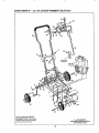
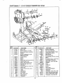
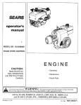
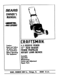
CRAFTSMAN
9"-
3.0 H.P. EDGER/TRIMMER
536.797561
14
20
13
9
23
Raf. Item 32
On Page 21
38
21
18
28
12
30
38
26
10
NOTE: ALWAYS USE ORIGINAL
EQUIPMENT PARTS Use of service/
replacement parts other than original
parts may void your warranty
ALL UNNUMBERED
ITEMS ARE INTERCHANGEAB_
WITH OPPOSITE SIDE
18
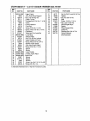
CRAFTSMAN
9" - 3.0 H.P. EDGER/TRIMMER
REFo
NO.
PART NO.
I
2
3
4
5
6
7
8
9
10
11
t2
13
t4
15
t6
17
18
19
2O
21
22
23
24
25
26
27
28
29
3O
323534-854
6852
120376
5717t
120230
8082
51615
51376
122027
180735
1203 93
315197
580330-853
310054
55273
310294
122007
6842
56924
122027
45222
25644
308253-853
310050-853
580292-853
5'1887
310715
2968
51333
48148
REF.
NO.
PART NAME
31
32
33
34
35
36
37
38
39
40
41
42
Edger Frame
Arm, Front Wheet Support
* Nut, 5/t6-18 Reg Hex
Plastic T-Knob
* Carriage Bolt, 5/16-18 x 1-1/4 in
Ctevis
* Pushnut Washer
Pivot Rod
Screw, 5/16-t8 x 1_1/4 In
* Screw, HHC 5/16-18 x 3_1t4 In.
* Ratwasher
Wheel and Tire Assembly
Lever Strap
Selector Plate
Nut, 5/'16-18 Hex Locknut
Upper Handle and Foam
* Screw,HHC 5/16-18 x 3/4 inn
Bracket, Curb Hopper
Grip, Hand Depth Adjust
* Screw, 5116-18 x 1.-1/4 In.
Spacer
Spring
Lower Handle
Handle, Depth Adjust
Control Rod
Spacer
Spacer
Washer
Screw, Hex Wd Ft 5/16-18 x 5/8
* Screw, 3/8=16 x 1 In,
w_
(*) Standard Hardware Items - May Be Purchased Locally.
19
536.797561
PART NO.
45171
36368
t499
310053
121913
1502
312548
51888
310896
121222
31O716
324779
PART NAME
Nut, Hx Wd FI Lock 3/8-16 Thd
Hairpin
Nut, Hex 3t8-16 Thd
Stud
Screw, 1/4-20 x 1-1/4 In_
Nut, Lock 1t4-20 Thd,
Decal Height Adjust
Spacer
Wheel Support Rod
Cotter Pin
Shoulder Bolt, 3/8-16 Thdo
Owner's Manual
(Not Illustrated)
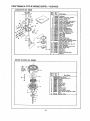
CRAFTSMAN
9"-
3.0 H.P. EDGER/TRIMMER
37
536.797561
t0
11
2
40
1
3
4
!
"t9
t8
REF. I
REF,
NO.
1
2
3
4
5
PARTNO.
31478t
181608
313011
320353
314794
6
7
8
9
10
1t
12
13
14
15
16
t7
18
19
20
2t
22
308155
308237
53407
173030
309300
181624
308254
308262
274654
305634
41t666
32668
43846
48697
120371
4935
2968
PART NAME
__
Pulley, Half
Screw, 5/16-24 x 1.0 HHC
Screw and Washer Assembly
Retainer
Engine, Craftsman 4 Cycle
Model 143814032
Torsion Spring
Spacer
Spacer
Screw, HHC, 5/16-18 x 3-314 In..
Engine Pulley Cover
Screw, HHC, 5/t6-24 x 3 In
Shoulder Boil, 3/8-16 Thd
Belt Guard
Locknut, Reg Hex 1/2-20 Thd
Pulley, Half
Screw, Tap, #10-16 x 112 In
V-Belt
Ball Bearing
Drive Shaft
Nut, 1/2-20 Thd
Shield Washer
Flatwasher
NO,
23
24
25
26
27
28
29
3O
31
32
33
34
35
36
37
38
39
40
41
42
43
i44
2O
PARTNO,
I 323500
I
1498
I 324860
i 315233
I 320222
1499
i
I 126211
I
88716
l
46023
1 308501
I 120396
I 308243
!308154-854
;
35075
: 315095
308466
312561
45602
1501
324476
324475
120393
PART NAME
Quill Arm Assembly
Nut, 5/16_18 Reg Hex
Decal, Blade Rotation, Edger
Compression Spring
Blade Guard
Nut, 5/16-18 Thd,
Carriage Bolt, 5/16-18 x 5/8 In
Blade
Nut, Wide Flange, 1/2-20 "l-hd_
Quill Support Assembly
Ftatwasher, _531x1.06x 095
Deflector
Strap
Hi-Pro Key
Spacer
Index Lever
Decal ,Angle Indicator
Flatwasher
Flatwasher, _203 x .56 x _040
Decal, Warning Edger Blade
Decal, Danger Blade, Edger
Flatwasher, 344x 69x 065
CRAFTSMAN
4 CYCLE ENGINE MODEL: 143.814032
r
iNo. i Z%.
i 2
3
4
5
6
7
8
9
10
11
12
13
14
15
16
17
29
9
11
18
19
14
20
21
22
23
24
25
26
27
28
29
P_Name
6322O8
l 631615
I 631767
Carburetor
Shaft Et Lever Assy+, Throttle
Spring, Throttle return
631O36 Shutter, ThrotlJe
_ 650506 Screw, Thmttte _ Choke shutter
j 63O766 Spring, idle regulating screw
650417
Screw, idle regulating
31841
Shaft _ Lever Assy.o Choke
63O735 Spring, Choke poshioning
Shutter, Choke
631562 Screw, Idle edjusm_ent
63O738 Sprig, Adjustment screw
63O739 Washer, Adjustment screw
°630740
"0".. Ring, Adjustment screw
63O737 Screw, Main adjustment
"630748
Plug, Welch
632164
FKting, Fuel
"630746
Plug, Welch
631049
Spring, Needle valve
630742
Gasket, Needle valve seat
"630932_ Inlet Needle, Seat, Gasket _ Spring
GASSy,
(lncL Nos, 18 r= 191
630750
asker, Diaphragm
*630978 Diaphragm Assy,, [IncL No,, 21}
63O751 Cover, IOiaphragm
65O545 Screw, Pan flex hd,, 6-32 x 3/8
632042 Spring, Choke return
631184 Washer, Flat
631971 Seal, Dust
631183 Washer, Felt
631893 Repair Kit {includes items
marked *)
REWIND STARTER NO. 590642A
ReL
_o.
1
2
5
6
7
8
9
10
11
12
13
_2
21
Part
No.
Part
Name
_90642AStarter, Rewind
5905_A Pin, Sp=ing (lncL
5OO6O0Washer
590615
5906O1
59O598
590616
590617
590618
590619
No_ 4)
Retainer
Washer
Spring, Brake
Dog, Stz_rter
Spring, Dog
Pulley
Spr_ng, Rewind
S90620 Cover, Spring
59O643 Housing Assy., Starter
590535 Rope, Starter (Length 98" _ 9/64"
dia.)
59O452 Handle, Starter
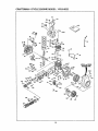
CRAFTSMAN
4 CYCLE
ENGINE
MODEL:
143.814032
131
75
\
MODELandSERIAL
NUMBERSHERE
370A
f
172
178
39O
22
/
327
D
CRAFTSMAN
[ l_ef.
! No.
P,
!
'
2
14
15
16
17
I8
19
20
25
25A
25B
26
3O
4O
4O
4O
41
41
41
42
42
42
43
45
46
48
4.9
50
60
65
66
69
70
.72
75
8O
81
82
83
84
86
89
9O
92
93
100
!02
103
110
119
120
125
125
126
126
130
131
!32
Part
No.
34708A
26727
28277
31334
31336
31335
650548
34593
32600
t33342
1650139
t30332
650561
4 CYCLE
ENGINE
MODEL:
143.814032
., I Ref.
Part
Na'ne
Cylinder Assy.. (Incl. Nos. 2, 20 e 72)
Pin, Dowel
Washer, Rat
Rod, Governor
Lever, Governor
Clamp, Governor lever
Screw, Hex washer hdo, 8-32 x 5116
Spring, Extension
Seal, Oil
Baffle, Blower housing
Screw, Fil, hd. Sems, 8-32 x 1/2
Locknut, Hex "Keps", 8-32
Screw, Hex washer hd. Durlok, 1/4-20
x 5/8
35902
CrankshaftAssy.
34514
Piston, Pin 8, Ring Assy. (Std.) (tncL
Nos,.41.42 Et 43)
34515
Piston, Pin _ Ring Assy. (,010 oversize) (incl. Nos, 41, 42 6" 43)
34516
Piston, Pin _ Ring Ass'y. (.020 over_
size) {tnc!. Nos. 41, 42 8` 48)
325388 Piston _ Pin Assy. (StdJ (Incl. No. 43)
32548B Piston 8- Pin Assy_ (oo10oversize)
(tncL No. 431
32549B Piston 8` Pin Assy. (.020 oversize)
(Incl, No. 43)
28986
Ring Set, Piston (Std.)
28987 Ring Sat, Piston(,010 oversize)
28988 Ring Set, P;ston(,020 oversize)
20381 Ring, Pistonpin retaining
30963B Rod Assy., Connecting (incl. Nos. 46
e 49)
32610A Bolt, Connectingrod
27241
Lifter, Valve
28594
Dipper, Oi!
33149A Camshaft (CompressionRelease)
29745
Extension, Blowerhousing
650128
Screw, Hex hd. Seres, 10-24 x 1/2
650751
Screw,
Hex hd. w/conical sprlng
washer, 1/4-20 x 7/16
"27677A Gasket, Cylindercover
35863
Cover, Cylinder{Incl. Nos_75, 80. 311
312)
27642
Plug, Pipe (1/4-18)
26208
Seal, Oil
30574
Shaft, Mechanical governor
305.90A Washer, Flat
30591
Gear, Governor (lncL No. 8t)
30588A Spool, Governor
29193
Ring, Retaining
65O488
Screw, Hex hd. Seres, 1/4-20 x 1_1/4
610961
Key, Flywheel
611080
Flywheel
650815
Washer, Betleville
650816
Nut, Flywheel
34443A Solid State Assy°
65O872
Stud, Solid state mounting
65O814
Screw, Torx To15 hex washer hd.
Seres, 10-24x 1
35182
Wire, Ground
29953C Gasket, Cylinderhead
30579A Head, Cylinder(Incl. No. 131)
29313C Valve, Exhaust(Std.) (Incl. No. 151)
29315C Valve, Exhaust (1/32" overJsize)(Incl.
NoD 151)
29314B Valve, Intake {Std.) |Incl. NoD151)
29315C Valve, Intake (t/32" oversize) (IncL
No. 151)
6021A Screw, Hexflange hd., 5/16-18 x 1-i/2
650694A Screw, Hex flange halo5/16-18 x 2
650708
Washer, Flat
r No,
Pazt
No.
I 13S
33636
150
151
169
170
171
172
173
174
178
179
182
t84
185
185
2OO
2O3
2O4
2O6
215
223
224
238
239
245
249
25O
260
261
274
275
2T/
284A
285
287
29O
292
298
300
301
31t
312
313
327
339
340
345
352
353
i
370AI
370B l
370C1
380
390
400
Part Name
PIug, Spark (Champion J-eC or
equivalent)
31672 Spdng, Valve
31673
Cap, Valve spring
"27234A Gasket, Breather
27666 Body, Valve cover
314t0
Element, Breather
34146 Cover, Breather
35350 Tube, Breather
650128 Screw, Hex hd. Seres, 10-24 x t/2
29752 Nut 8` Lockwasher,1/4-28
30593 Clip, Groundwire
6201
Screw, Hex hd, 1/4.28 x 7/8
"31688A Gasket, Carburetor
34597 Pipe, Intake
31341 Link, Governorto thmttte
133858A Control Assy., Speed (IncL Nos. 203
thpJ 206, 25A Et25B)
31342
Spring, Compression
B505€9
Screw, FiL hd., 5-40 x 7/16
610973
Terminal Assy.
32410
Knob, Speed control
65O451
Screw, Hex hd. Seres, 1/4-20 x t
*32649A Gasket, Intake to cylinder
65O932
Screw, Hex washer hd shoulder,
10-32 x 49/64
34338 Gasket, Air cleaner
35O66 Fitter, Air cleaner {paped
35797 Collar, Air cleaner
35065 Cover, Air cleaner
35585 Housing, Blower
29212 Screw, Hex hd. Beans,1/4-28 x 7/16
"3008tA Gasket, Exhaust
3O996 Muffler
650493 Screw, Hex hd..Same, 1/4`20 x 1-3/4
30997 Cover, Muffler
65O665 Screw, Hexwasher hd_thread cutting,
1/4-15 x 7/8
34694
Cup, Starter
650884 Screw, Hex washer hd., 8-32 x 1/2
29774 Line, Fuel
26460 Clamp, Fuel line
6_665
Screw, Hex washerhdothreadcutting,
1/4-15 x 718
32660A Tank Assy, Fuel{lncL Nos. 292 Et301)
33O32 Cap Assy., Fuel
27625
Plug Assy., Oil {IncL No, 312)
*29673 Gasket, O!: plug
34080 Spacer, Flywheel key'
35392 Plug, Starter
28212 Spacer, Tank bracket
32661
Bracket, Fuel tank mounting
32664 Baffle, Heat
35883 Exten-_sion,
Baffle
650884 Screw, Hex washer hd.., 8-32 x 1/2
34346
Decal, Lubrication
34150
Decal/Choke
35344
Decal, Throttle
632208
Carburetor (Incl, No. 184)
590642A Starter, Rewind
33233A Gasket Set (Incl. items marked °)
RPM Setting:
Low Speed: t700-2000
High Speed: 3300-3600
=
i
*indicates Parts Includedin
Gaskst Set, RefoNo.,400.
I
f in original production, the speed centre! assembly is riveted to the blower housing baffled Replacement speed control assembly
and nuls for mounting,, Replacement baffle has threaded holes.
23
_nctudos screws
CRRFrSMRN®
OWNER'S
MANUAL
9 INCH3.0 HORSEPOWER
EDGER/3"RIMMER
MODEL NO.
536,797561
Each
EDGER/fRtMMER
NUMBER
has
on a model
its own
plate on the frame
behind
the engine.
Each
ENGINE
found
on the BLOWER
Always
mention
has its own
All parts may
Roebuck
and
Retail Stores.
MODEL
NUMBER
HOUSING.
these MODEL
requesting
service
EDGER/TRIMMER_
or
Repair
NUMBERS
Parts
for
when
your
be ordered through any Sears,
Compady
Service
Centers
and
WHEN ORDERING
REPAIR PARTS,
GIVE THE FOLLOWING INFORMATION:
HOW TO ORDER
REPAIR PARTS
MODEL
ALWAYS
* PRODUCT- "EDGERff'RIMMER"
* MODEL NUMBER - 536,797561
* ENGINE MODEL NUMBER - 143.814032
* PART NUMBER
* PART DESCRIPTION
"Your Sears merchandise has added value when you
consider that Sears has service units nationwide staffed
with Sears trained technicians. °Professional technicians
specifically trained on Sears Products, having the parts,
tools and equipment to insure that we meet our pledge
to you_ we service what we sell"
............
llll
j
ill
i
L
ll/llll
SEARS, ROEBUCK AND CO. , Hoffman Estates, IL 60179
324779 08f24/92
Printed in U_S.Ao