1
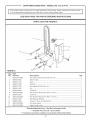
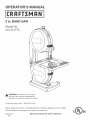
9 in. BAND SAW
Model No.
315.214770
_1_ WARNING: To reduce the risk of injury,
the user must read and understand the
operator's manual before using this product.
Customer
HeUp Line: 1-800-932-3188
Sears, Roebuck and Co., 3333 BeverUy Rd., Hoffman
Visit the Craftsman web page: www.sears.com!craftsman
983000-577
8-04
Save this manual
Estates, IL 60179 USA
for future
reference
[] Warranty ..........................................................................................................................................................................
2
[] Introduct(on .....................................................................................................................................................................
2
[] General Safety Rules ....................................................................................................................................................
3-4
[] Symbols ........................................................................................................................................................................
5-6
[] Electrical ..........................................................................................................................................................................
7
[] Glossary of Terms ............................................................................................................................................................
8
[] Features ......................................................................................................................................................................
9-10
[] Tools Needed .................................................................................................................................................................
11
[] Loose Parts List .............................................................................................................................................................
11
[] Assembly ..................................................................................................................................................................
12-18
[] Operation ..................................................................................................................................................................
18-20
[] Maintenance .............................................................................................................................................................
21-22
[] Troub(eshoot(ng .............................................................................................................................................................
23
[] Exploded View and Parts L(st ........................................................................................................................................
24
[] Parts Order(ng/Serv(ce .....................................................................................................................................
FULL ONE YEAR WARRANTY
ON CRAFTSMAN
Back Page
TOOL
(f this CRAFTSMAN
tool falls to give complete satisfaction within one year from the date of purchase, RETURN (T TO
THE NEAREST SEARS STORE OR SEARS SERV(OE CENTER IN THE UN)TED STATES, and Sears w(l( repair (t, free
of charge.
(f this CRAFTSMAN
of purchase.
too( is used for commercia( or renta( purposes, this warranty applies for on(y 90 days from the date
This warranty gives you specific legal rights, and you may a(so have other rights which vary from state to state.
Sears, Roebuck
and Oo., Dept. 817WA, Noffrnan Estates, (L 60179
This too( has many features for making its use more p(easant and enjoyab(e. Safety, performance, and dependability
have been given top priority in the design of th(s product making it easy to maintain and operate.
_
WARMNG:Readandunderstand
all
instructions. Failuretofollowallinstructions
listedbelow,
mayresultin electricshock,fireand/orserious
personalinjury.
READ ALL mNSTRUCTmONS
[] KNOW YOUR POWER TOOL. Read the operator's
manual carefully. Learn the applications and limitations
as well as specific potential hazards related to this too!.
[] GUARD AGAINST ELECTRICAL SHOCK by
preventing body contact with grounded surfaces.
For example: pipes, radiators, ranges, refrigerator
enc!osures.
[] KEEP GUARDS iN PLACE and in working order. Never
operate the tool with any guard or cover removed.
Make sure all guards are operating properly before
each use.
[] REMOVE ADJUSTING KEYS AND WRENCHES.
Form habit of checking to see keys and adjusting
wrenches are removed from tool before turning it on.
[] KEEP THE WORK AREA CLEAN. Cluttered work
areas and work benches invite accidents.
[] DO NOT USE IN DANGEROUS ENWRONMENTS. Do
not use power tools near gasoline or other flammable
liquids, in damp or wet locations or expose them to
rain. Keep work area well lighted.
[] KEEP CHILDREN AND WSJTORS AWAY. All visitors
should wear safety glasses and be kept a safe distance
from work area.
[] MAKE WORKSHOP CNILDPROOF with padlocks,
master switches, or by removing starter keys.
[] DO NOT FORCE THE TOOL. it will do the job better
and safer at the rate for which it was designed.
[] USE THE RIGHT TOOL. Do not force the tool or
attachment to do a job for which it was not designed.
[] USE THE PROPER EXTENSION CORD. Make sure
your extension cord is in good condition. When using
an extension cord, be sure to use one heavy enough to
carry the current your product will draw. An undersized
cord will cause a drop in line voltage resulting in toss of
power and overheating. A wire gage size (A.W.G.) of at
least 16 is recommended for an extension cord 25 feet
or less in length, if in doubt, use the next heavier gage.
The smaller the gage number, the heavier the cord.
[] WEAR PROPER APPAREL. Do not wear loose
clothing, neckties, or jewelry that can get caught in the
tool's moving parts and cause personal injury. Nonslip
footwear is recommended when working outdoors.
Wear protective hair covering to contain long hair.
[] ALWAYS WEAR SAFETY GLASSES WITH SIDE
SHIELDS. Everyday eyeglasses have only impactresistant lenses; they are NOT safety glasses.
[] SECURE WORK. Use clamps or a vise to hold work
when practical, it's safer than using your hand and it
frees both hands to operate tool.
[] DO NOT OVERREACH. Keep proper footing and
balance at all times.
[] MAINTAIN TOOLS WITH CARE. Keep tools sharp
and clean for best and safest performance. Follow
instructions for lubricating and changing accessories.
[] DISCONNECT ALL TOOLS. When not in use, before
servicing, or when changing attachments, blades, bits,
cutters, etc., aNtools should be disconnected from
power source.
[] REDUCE THE RISK OF UNINTENTIONAL
STARTING. Be sure switch is off when plugging in.
[] USE RECOMMENDED ACCESSORIES. Consult the
operator's manual for recommended accessories. The
use of improper accessories may cause risk of injury.
[] NEVER STAND ON TOOL. Serious injury could occur
if the tool is tipped or if the blade is unintentionally
contacted.
[] CHECK DAMAGED PARTS. Before further use of
the tool, a guard or other part that is damaged should
be carefully checked to determine that it wil! operate
properly and perform its intended function. Check for
alignment of moving parts, binding of moving parts,
breakage of parts, mounting and any other conditions
that may affect its operation. A guard or other part that
is damaged must be properly repaired or replaced by
an authorized service center to avoid risk of personal
injury.
[] DIRECTION OF FEED. Feed work into a blade or
cutter against the direction or rotation of the blade or
cutter only.
[] NEVER LEAVE TOOL RUNNING UNATTENDED.
TURN POWER OFF. Do not leave too! until it comes to
a complete stop.
[] DO NOT ABUSE CORD. Never carry too! by the cord
or yank it to disconnect from receptacle. Keep cord
from heat, oi!, and sharp edges.
[] PROTECT YOUR LUNGS. Wear a face or dust mask if
the cutting operation is dusty.
[] PROTECT YOUR NEARtNG. Wear hearing protection
during extended periods of operation.
[] BLADE COASTS AFTER TURN OFF.
[] KEEP TOOL DRY, CLEAN, AND FREE FROM
OIL AND GREASE. Always use a clean cloth when
cleaning. Never use brake fluids, gasoline, petroleumbased products, or any solvents to clean tool.
[] INSPECT TOOL CORDS AND EXTENSION CORDS
PERIODICALLY and, if damaged, have repaired by a
qualified service technician. Stay constantly aware of
cord location and keep it well away from the rotating
wheel.
[] NEVER USE IN AN EXPLOSIVE ATMOSPHERE.
Normal sparking of the motor could ignite fumes.
[] USE ONLY OUTDOOR EXTENSION CORDS with
approved ground connection that are intended for use
outdoors and so marked.
[] BE SURE THE BLADE PATH IS FREE OF NAILS.
inspect for and remove nails from lumber before
cutting.
[] AVOIDAWKWARD
OPERATIONS
ANDHANDPOSITIONSwherea suddenslipcouldcauseyourhand
to moveintothe blade.ALWAYS
makesureyouhave
goodbalance.
[] ALLOWTHEMOTORTO COME UP TO FULL SPEED
[] BEFORE CHANGING THE SETUP, REMOVING COVERS, GUARDS, OR BLADES, unplug the saw and remove the switch key.
[] KEEP BLADES CLEAN, SHARP, AND WtTH SUFFiCIENT SET. Sharp blades minimize stalling and kickbacks.
before starting a cut to avoid binding or stalling.
[] DO NOT USE TOOL iF SWITCH DOES NOT TURN iT
ON AND OFF. Have defective switches replaced by an
authorized service center.
[] ALWAYS TURN OFF SAW before disconnecting it to
avoid accidental starting when reconnecting to a power
[] REPLACEMENT PARTS. All repairs, whether electrical
or mechanical, should be made by a qualified service
technician at an authorized service center.
[] DO NOT OPERATE THiS TOOL WHILE UNDER THE
INFLUENCE OF DRUGS, ALCOHOL OR ANY MEDICATION.
[] WHEN SERViCiNG USE ONLY iDENTiCAL REPLACEMENT PARTS. Use of any other parts may
create a hazard or cause product damage.
[] STAY ALERT AND EXERCISE CONTROL. Watch
what you are doing and use common sense. Do not
operate tool when you are tired. Do not rush.
[] MAKE SURE WORK AREA HAS AMPLE LIGHTING
to see the work and that no obstructions will interfere
with safe operation BEFORE performing any work using the saw.
[] SAVE THESE INSTRUCTIONS. Refer to them fiequently and use them to instruct other users. If you
loan someone this tool, loan them these instructions
also.
[] MAINTAIN PROPER ADJUSTMENT OF BLADE TEN-
source.
[] KEEP HANDS AWAY FROM CUTTING AREA. Do
not hand hold pieces so small that your fingers go
under the blade guard. Do not reach underneath work
or in blade cutting path with your hands and fingers
for any reason.
[] NEVER CUT MORE THAN ONE PIECE AT A TiME or
stack more than one workpiece on the saw table at a
time.
[] FIRMLY CLAMP OR BOLT the saw to a stable, level
workbench or table. The most comfortable table height
is approximately waist height.
[] DO NOT FEED THE MATERIAL TOO QUICKLY. Do
not force the workpiece against the blade.
SION, BLADE GUIDES, AND THRUST BEARINGS.
[] ADJUST UPPER GUIDE TO JUST CLEAR WORKPIECE.
[] HOLD WORKPIECE
[] USE ONLY CORRECT BLADES. Use the right blade
size, style, and cutting speed for the material and the
type of cut. Blade teeth should point down toward the
table.
FRMLY AGAINST TABLE.
WARNING:. Some dust created by power sanding, sawing, grinding, drilling, and other construction
activities contains chemicals known to cause cancer, birth defects or other reproductive harm. Some
examples of these chemicals are:
[] BEFORE MAKING A CUT, BE SURE ALL ADJUSTMENTS ARE SECURE.
[] ALWAYS SUPPORT LARGE WORKPIEOES while
cutting to minimize risk of blade pinching and kickback. Saw may slip, walk, or slide while cutting large or
heavy boards.
[] DO NOT REMOVE JAMMED CUTOFF PIECES unti!
blade has stopped.
[] NEVER START THE TOOL when the blade is in contact with the workpiece.
[]
lead from lead-based paints,
[]
crystalline silica from bricks and cement and other
masonry products, and
[]
arsenic and chromium from chemically-treated
lumber.
Your risk from these exposures varies, depending on
how often you do this type of work. To reduce your
exposure to these chemicals, work in a well ventilated
area, and work with approved safety equipment, such
as those dust masks that are specially designed to
filter out microscopic particles.
[] NEVER TOUCH BLADE or other moving parts during
use.
WARNING:
The blade guides have been preset at the factory. These settings are functional for some applications.
We recommend that you check and adjust blade guide settings before first use of the saw. Refer to "ADJUSTING
THRUST BEARINGS, BLADE GUIDE SUPPORT, AND BLADE GUIDES" procedures explained in the ADJUSTMENTS section of this operator's manual.
4
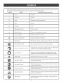
Someof the followingsymbolsmaybe usedonthis tool. Pleasestudythemandlearntheirmeaning.Proper
interpretation
ofthesesymbolswinallowyouto operatethetool betterandsafer.
SYMBOL
NA!Vi
E
DESJG NATION/EXPLANATION
V
Volts
Voltage
A
Amperes
Current
Hz
Hertz
Frequency (cycles per second)
W
Watt
Power
Minutes
Time
Alternating Current
Type of current
Direct Current
Type or a characteristic
No Load Speed
Rotational speed, at no load
Class HConstruction
Double-insulated
Per Minute
Revolutions, strokes, surface speed, orbits etc., per minute
Wet Conditions Alert
Do not expose to rain or use in damp !ocations.
Read The Operator's Manual
operator's
manual
before
To reduce the
risk of
injury,using
user this
mustproduct.
read and understand
Eye Protection
Always wear safety goggles or safety glasses with side
shields and a full face shield when operating this product.
Safety Alert
Precautions that involve your safety.
No Hands Symbol
Failure to keep your hands away from the blade will result in
serious personal injury.
No Hands Symbol
Failure to keep your hands away from the blade will result in
serious personal injury.
min
_L,
no
.../rain
No Hands Symbol
®
of current
construction
Failure to keep your hands away from the blade will result in
serious personal injury.
No Hands Symbol
Failure to keep your hands away from the blade wil! result in
serious personal injury.
Hot Surface
To reduce the risk of injury or damage, avoid contact with
any hot surface.
5
Thefol!owingsignalwordsandmeanings
areintendedto explainthe levelsofriskassociated
withthisproduct.
SYMBOL
SIGNAL
MEANING
DANGER:
hdicates an imminently hazardous situation, which, if not avoided, wil!
result in death or serious injury.
WARNING:
hdicates a potentially hazardous situation, which, if not avoided, could
result in death or serious injury.
CAUTmON:
hdicates a potentially hazardous situation, which, if not avoided, may
result in minor or moderate injury.
CAUTION:
(Without Safety Alert Symbol) Indicates a situation
property damage.
that may result in
SERVmCE
Servicing requires extreme care and knowledge and
should be performed only by a qualified service technician. For service we suggest you return the product to
your nearest AUTHORIZED SERWOB CENTER for repair.
When servicing, use only identical replacement parts.
_
_
WARNING: To avoid serious personal injury, do not
attempt to use this product until you read thoroughly
and understand completely the operator's manual.
Save this operator's manual and review frequently for
continuing safe operation and instructing others who
may use this product.
WARNING:
The operation of any power tool can result in foreign objects being thrown into your eyes, which
can result in severe eye damage. Before beginning power tool operation, always wear safety
goggles or safety glasses with side shields and a full face shield when needed. We recommend
Wide Vision Safety Mask for use over eyeglasses or standard safety glasses with side shields.
Always use eye protection which is marked to comply with ANSI Z87.1.
SAVE THESE iNSTRUCTiONS
EXTENSION
CORDS
SPEED
Use only 3-wire extension cords that have 3-prong
grounding plugs and 3-pole receptacles that accept the
tool's plug. When using a power tool at a considerable
distance from the power source, use an extension cord
heavy enough to carry the current that the tool will draw.
An undersized extension cord will cause a drop in line
voltage, resulting in a loss of power and causing the motor
to overheat. Use the chart provided below to determine
the minimum wire size required in an extension cord. Only
round jacketed cords listed by Underwriter's Laboratories
(UL) should be used.
"*Ampere rating (on tool faceplate)
0-2,0
2.1-3,4
Cord Length
3,5-5.0
5.1W,0
7.1-12,0
12.1-16,0
Wire Size (A.W.G.)
25'
16
16
16
16
14
14
50'
16
16
16
14
14
12
100'
16
16
14
12
10
--
**Used on 12 _uge o20 amp cimuit.
NOTE: AWG = American Wf_ Gauge
When working with the tool outdoors, use an extension
cord that is designed for outside use. This is indicated by
the letters "WA" on the cord's jacket.
Before using an extension cord, inspect it for loose or
exposed wires and cut or worn insulation.
_
WARMNG:
Keep the extension cord clear of the
working area. Position the cord so that it will not get
caught on lumber, tools or other obstructions while
you are working with a power tool. Failure to do so
can result in serious personal injury.
WARNING:
AND WIRING
The no-load speed of this too! is approximately 3,000
sfpm. This speed is not constant and decreases under
a load or with lower voltage. For voltage, the wiring in a
shop is as important as the motor's horsepower rating. A
line intended only for lights cannot properly carry a power
tool motor. Wire that is heavy enough for a short distance
wil! be too light for a greater distance. A line that can
support one power tool may not be able to support two
or three tools.
GROUNDING
INSTRUCTIONS
In the event of a malfunction or breakdown, grounding
provides a path of least resistance for electric current to
reduce the risk of electric shock. This tool is equipped with
an electric cord having an equipment-grounding
conductor and a grounding plug. The plug must be plugged into a
matching outlet that is properly installed and grounded in
accordance with all local codes and ordinances.
Do not modify the plug provided. If it will not fit the outlet,
have the proper outlet installed by a qualified electrician.
Improper connection of the equipment-grounding conductor can result in a risk of electric shock. The conductor
with insulation having an outer surface that is green with or
without yellow stripes is the equipment-grounding
conductor. If repair or replacement of the electric cord or
plug is necessary, do not connect the equipmentgrounding conductor to a live terminal.
Check with a qualified electrician or service personnel if
the grounding instructions are not completely understood,
or if in doubt as to whether the tool is properly grounded.
Repair or replace a damaged or worn cord immediately.
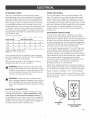
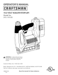
This toot is intended for use on a circuit that has an outlet
like the one shown in figure 1. It also has a grounding pin
like the one shown.
Check extension cords before each
use. If damaged replace immediately. Never use tool
with a damaged cord since touching the damaged
area could cause electrical shock resulting in serious
injury.
ELECTRICAL
®
CONNECTION
This tool is powered by a precision built electric motor.
It should be connected to a power supply that is 120
volts, 60 Hz, AC only (normal household current)° Do
not operate this too! on direct current (DC). A substantial
voltage drop will cause a loss of power and the motor will
overheat. If the saw does not operate when plugged into
an outlet, double check the power supply.
®
GROUNDING
PiN
COVER OF GROUNDED
OUTLET BOX
Fig. 1
Anti=KickbackPawls(radialarm
and table saws}
A device which, when properly installed and maintained,
is designed to stop the workpiece from being kicked back
toward the front of the saw during a ripping operation.
Arbor
Non=Through Cuts
Any cutting operation where the blade does not extend
completely through the thickness of the workpiece.
A cutting operation made with the blade at any angle
other than 90 ° to the table surface.
Push Blocks and Push Sticks
Devices used to feed the workpiece through the saw
blade during cutting operations. A push stick (not a push
block) should be used for narrow ripping operations.
These aids help keep the operator's hands well away from
the blade.
Chamfer
A cut removing a wedge from a block so the end (or part
of the end) is angled rather than at 90 ° .
Pilot Hole (drill presses}
A small hole drilled in a workpiece that serves as a guide
for drilling large holes accurately.
Compound Cut
A cross cut made with both a miter and a bevel angle.
Resaw
A cutting operation to reduce the thickness of the workpiece to make thinner pieces.
The shaft on which a blade or cutting tool is mounted.
Bevel Cut
Crosscut
A cutting or shaping operation made across the grain or
the width of the workpiece.
Cutter Head {planers and jointers)
A rotating piece of adjustable blades. The cutter head
removes material from the workpiece.
Dado Cut
A non-through cut which produces a square-sided notch
or trough in the workpiece (requires a special blade).
Featherboard
A device used to help control the workpiece by guiding it
securely against the table or fence during any ripping
operation.
FPM or SPM
Feet per minute (or strokes per minute), used in reference
to blade movement.
Freehand
Performing a cut without the workpiece
fence, miter gauge, or other aids.
being guided by a
Gum
A sticky, sap-based residue from wood products.
Heel
Alignment of the blade to the fence.
Kerf
The matedal removed by the blade in a through cut or the
slot produced by the blade in a non-through or partial cut.
Kickback
A hazard that can occur when the blade binds or stalls,
throwing the workpiece back toward operator.
Leading End
The end of the workpiece pushed into the tool first.
Miter Cut
A cutting operation made with the workpiece at any angle
to the blade other than 90 °.
Resin
A sticky, sap=based substance that has hardened.
Revolutions Per Minute (RPM)
The number of turns completed by a spinning object in
one minute.
Ripping or Rip Cut
A cutting operation along the length of the workpiece.
Riving Knife/Spreader/Splitter
(table saws}
A metal piece, slightly thinner than the blade, which helps
keep the kerf open and also helps to prevent kickback.
Saw Blade Path
The area over, under, behind, or in front of the blade. As
it applies to the workpiece, that area which win be or has
been cut by the blade.
Set
The distance that the tip of the saw blade tooth is bent (or
set) outward from the face of the blade.
Snipe (planers}
Depression made at either end of a workpiece by cutter
blades when the workpiece is not properly supported.
Throw=Back
The throwing back of a workpiece usually caused by the
workpiece being dropped into the blade or being placed
inadvertently in contact with the blade.
Through Sawing
Any cutting operation where the blade extends completely
through the thickness of the workpiece.
Workpiece or Material
The item on which the operation is being done.
Worktable
Surface where the workpiece rests while performing a
cutting, drilling, planing, or sanding operation.
PRODUCT
SPECmFmCATmONS
Blade Width ...............................................
1/8 in. to 3/8 in.
Blade Length ......................................................
59-1/4 in.
Frame to Blade Capacity .............................................
9 in.
Cutting Thickness Capacity ................................
3-1/8 in.
Table Size ........................................ 11-3/8 in. x 11-3/8 in.
Table Ti}t .................................................................
input ...........................
120 Volt, 60Hz, AC Only, 2.3 Amps
No Load Speed .............................................. 3,000 SFPM
Overal! Dimensions ........... 19-1/2 in. x 12-1/2 in. x 28 in.
Net Weight ...............................................................
Dust Port ..............................................................
37 Ibs.
1-3/4 in.
0 ° - 45 °
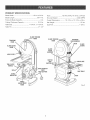
BLADETENSION
KNOB
BLADETENSION
KNOB
TRACKING
KNOB
TRACKING
VIEW WINDOW
BLADE
GUARD
BLADE GUIDE
KNOB
BLADE
GUIDE
SUPPORT
LOCKLEVER
SWITCH
AND
SWITCHKEY
OUBTEXHAUBT
PORT
AND ADAPTER
SCALE
SCALE
INDICATOR
SAW BLADE
SAW TABLE
LATCH
ANGLE
AOJUBTMENT
KNOB
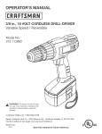
Fig. 2
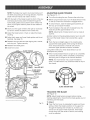
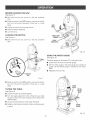
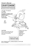
KNOW YOUR
BAND SAW
Saw Blade
The band saw comes with a standard saw blade installed.
See Figure 2.
Before attempting to use this product, familiarize yourself
with all operating features and safety rules.
Two extra saw blades are included with the loose parts.
Angle Adjustment
Knob
Tilts the saw table for bevel cutting.
The band saw has a square 11-3/8 in. aluminum saw table
with tilt control for maximum accuracy. The throat plate,
installed in the saw table at the factory, allows for blade
clearance.
Saw Table
Blade Guard
Protects the operator from coming in contact with the
blade.
Scale
Blade Guide Support
Helps keep the blade from twisting during operation.
Indicator
Switch and Switch Key
Your band saw has an easy access power switch. To lock
in the OFF position, remove the yellow switch key. Place
the key in a location inaccessible to children and others
not qualified to use the tool.
Blade Guide Knob with Lock Lever
Use the blade guide knob and lock lever to adjust the
blade guide assembly to keep the blade from twisting or
breaking. Always lock the blade guide assembly in place
before turning on the band saw.
Blade Tension
and Scale
The scale and scale indicator show the angle or degree
the saw table is tilted for bevel cutting.
Table Lock Handle
Loosening the table lock handle allows the saw table
to be tilted at different angles. Tightening the table lock
handle locks the saw table in place.
Knob
Controls blade tension when changing blades and making
adjustments for various sawing applications.
Dust Exhaust Port and Adapter
A 1-3/4 in. dust exhaust port makes dustless cutting possible by blowing the dust away from the user. Attach the
adapter to the dust exhaust port when using a dust collection system or shop vac.
Tracking
Knob
Adjusts tracking to keep blade centered on the wheels.
Tracking View Window
The tracking view window makes tracking adjustments
easier to see.
Latch
Easy-open latches allow front cover to be opened for
making adjustments.
10
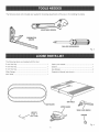
Thefollowingtools(notincluded)areneededforcheckingadjustments
ofthesawor forinstallingtheblade:
ADJUSTABLE
WRENCH
PHiLLiPS$OREWORIVER
Fig. 3
The following items are included with the tool:
1
Table Lock Handle ............................................................
1
4 mm Hex Key ..................................................................
1
Washer .............................................................................
!
5 mm Hex Key ..................................................................
1
Saw Blades ......................................................................
2
Miter Gauge ......................................................................
!
Operator's Manual (not shown) ........................................
!
Saw Table .........................................................................
!
3 mm Hex Key ..................................................................
HEXKEY
(3 ram, 4
__
WASHER
mm, Bmm)
Fig. 4
11
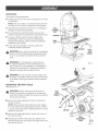
UNPACKING
Thisproductrequiresassembly.
[] Carefully
lift sawfromthecartonandplaceit on a level
worksurface.
NOTE:Thistoolis heavy.Toavoidbackinjury,lift with
yourlegs,notyourback,andget helpwhenneeded.
[] hspectthetoolcarefullyto makesurenobreakage
or
damageoccurredduringshipping.
[] Donotdiscardthepackingmaterialuntilyouhave
carefullyinspectedandsatisfactorily
operatedthetool.
[] Thesawisfactorysetforaccuratecutting.After
assembling
it, checkforaccuracy,ffshippinghas
influenced
thesettings,refertospecificprocedures
explainedinthis manual.
[] ff anypartsaredamagedor missing,pleasecall
1-800-932-3188
forassistance.
_
TABLE
ALIGNING
BOLT
TABLE
LOCK
HANDLE
WARNING:If anypartsaremissing,do notoperate
thistooluntilthe missingpartsarereplaced.Failure
to do socouldresultin possibleseriouspersonal
injury.
WARNING:Donotattemptto modifythistool
or createaccessories
notrecommended
foruse
withthistool.Anysuchalterationor modification
is
misuseandcouldresultina hazardous
condition
leadingto possibleseriouspersonalinjury.
Fig.5
_ll WARNING:Donotconnect
ttoopower
supplyuntil
assemblyis complete.Failure
complycouldresult
inaccidentalstartingandpossibleseriouspersonal
injury.
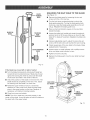
MOUNTING
THE SAW TABLE
See Figures 5 - 6.
_
TABLE
LOCK
HANDLE
WARNING:
Always make sure the band saw is
securely mounted to a workbench or an approved
work stand. Failure to heed this warning can result in
serious personal injury.
[] Remove the angle adjustment knob from the side of
the saw housing.
NOTE: Take care when removing the nut and washer
from the center of the angle adjustment knob. There is
a spring in the center that is released after the nut and
washer are removed.
[] Remove the table aligning bolt, washer, and wing nut
from the saw table.
ANGLE
ADJUSTMENT
KNOB
[] Standing at the front of the band saw, slide the saw
table through the slot moving from the right side of the
saw table to the left.
12
[] Hnsert
thewasheronthethreadedendof thetabletock
handle.Thetablelockhandleis springloadedand
is releasedbypullingthehandleawayfromthesaw
housing.Tightenthesawtableto thesawhousingby
ratchetingthetablelockhandleclockwiseor byfinger
tighteningthetablelockhandle.
[] Reattach
the angleadjustmentknobusingthespring,
washer,
andnut.
[] Reattach
thetablealigningbolt,washer,andwingnut
to thesawtable.
NOTE:Thewingnutgoesbelowthe sawtable.
CLAMPmNG
MOUNTmNG
[] Follow the last three steps in the section Mounting
Band Saw to Workbench.
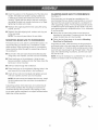
BAND SAW TO WORKBENCH
See Figure 7.
Hfthe band saw is to be used as a portable tool, it is
recommended that you fasten it permanently to a mounting board that can easily be clamped to a workbench or
other supporting surface. The mounting board should be
of sufficient size to avoid tipping of saw while in use. Any
good grade plywood or chipboard with a 3/4 in. thickness
is recommended.
[] Mount saw to board using holes in saw base as a
template for hole pattern. Locate and mark the holes
where the band saw is to be mounted.
BAND SAW 3"0 WORKBENCH
Hfthe band saw is to be used in a permanent location, we
recommend that you secure it to a workbench or other
stable surface. When mounting the saw to a workbench,
holes should be drilled through the supporting surface of
the workbench.
Hflag bolts are used, make sure they are long enough to
go through holes in the saw base and material the saw is
being mounted to. Hfmachine bolts are being used, make
sure bolts are tong enough to go through holes in the saw
base, the material being mounted to, and the lock washers and hex nuts.
[] Each hole in the saw base should be bolted securely
using bolts, lock washers, and hex nuts (not included).
NOTE: Htmay be necessary to countersink hex nuts and
washers on bottom side of mounting board.
[] Place band saw on the workbench. Using the saw
base as a pattern, locate and mark the holes where the
band saw is to be mounted.
[] Drill four holes through the workbench.
[] Place band saw on the workbench aligning holes in the
saw base with the holes drilled in the workbench.
[] Hnsert all four bolts (not included) and tighten securely
with lock washers and hex nuts (not included).
NOTE: AI! bolts should be inserted from the top. Hnstall
the lock washers and hex nuts from the underside of
the bench.
Supporting surface where band saw is mounted should
be examined carefully after mounting to insure that no
movement during use can result. Hfany tipping or walking is noted, secure workbench or support surface before
beginning cutting operation.
Fig. 7
13
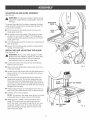
ADJUSTmNG
See Figure 8.
BLADE
GUmDE ASSEMBLY
WARNING: To avoid personal injury, maintain proper
adjustment of blade tension, blade guides, and thrust
bearings.
BLADE GUIDE
KNOB
To prevent the blade from twisting or breaking, the blade
guide assembly should always be set approximately 1/8
in. above the workpiece.
[] Turn the lock lever counterclockwise
blade guide assembly.
to unlock the
LOCK
LEVER
[] As a guide, use a scrap piece of the same wood you
are about to cut to set the height of the blade guide
assembly. Adjust blade guide assembly by turning the
blade guide knob.
[] Lock blade guide assembly in place by turning the lock
lever clockwise.
[] Always lock the blade guide assembly in place before
turning on the band saw.
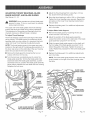
mNSTALUNG
AND ADJUSTmNG
THE BLADE
See Figures 9 - 10.
_
WARNING:
Always wear safety goggles or safety
glasses with side shields to protect your eyes while
uncoiling band saw blades. Failure to heed this
warning could result in a serious eye injury.
[] Loosen and remove the wing nut and table aligning
bolt from the saw table.
Fig. 8
[] Remove the saw table before opening the front cover
of the saw housing.
[] Loosen the two set screws that hold the blade guard in
place using the 4 mm hex key provided, then remove
the blade guard.
[] Turn the lock lever counterclockwise to unlock the
blade guide assembly. Turning the blade guide knob
(clockwise raises the blade guide assembly; counterclockwise lowers it), position the blade guide assembly
about halfway between the saw table and saw housing.
Retighten the lock lever.
SETSCREWS
[] Release blade tension by loosening the 8 mm hex nut
then turning the blade tension knob counterclockwise.
[] Carefully remove the old blade.
NOTE: The spring on the upper wheel allows the wheel
to be pulled down for easier removal of the blade.
\
[] Wearing gloves, carefully uncoi! the blade at arm's
length. If the new blade was oiled to prevent rusting, it may need to be wiped to keep the oil from your
workpiece. Carefully wipe in the same direction the
teeth are pointing so the rag does not catch on the
teeth of the saw blade.
14
WING
NUT
SAW
TABLE
TABLE ALIGNING
BOLT
Fig. 9
[]
[]
[]
[]
[]
[]
[]
NOTE:Theblademayneedto beturnedinsideout if
theteetharepointinginthe wrongdirection.Holdthe
bladewithbothhandsandrotateit inward.
Withtheteethof thebladetowardthefrontof thesaw
andfacingdownward,placethe bladethroughthe
lowerbladeguidesandaroundthelowerwheel.Pull
downontheupperwheelto placethesawbladeon
thewheel.
Slowlyturnthe upperwheelto therightor clockwise
byhandto centerthebladeonthe rubbertires.
Adjustthebladetension.Checkor adjustthe blade
tracking.
Adjustbothupperandlowerbladeguidesandthrust
bearings.
Seepage16.
Reattach
thesawtableandthealigningbolt,washer,
andwingnut.T(ghtensecurely.
Reattach
the bladeguard.
Closefrontcover.
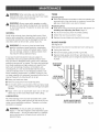
ADJUST(NG
BLADE
TENS(ON
See Figures 10- 11.
[] Turn off and unplug the saw. Remove the switch key.
[] Before using the band saw, turn the blade tension knob
on the top of the saw clockwise to engage tension.
[] To check tension, raise the blade guide assembly a(l
the way up to expose the blade.
[] Push the blade to the side w(th moderate force; the
blade should flex approx(mately 1,/8 in.
NOTE: Adjustments
anytime.
of blade tension can be made at
Another method of checking blade tension has to do with
the sound the blade makes when plucked like a guitar
str(ng.
[] Pluck the back straight edge on the coasting side
opposite the blade guides while turning the tension
knob. Sound should be a musical note. Sound
becomes h(gher pitched as tension increases.
Using either method to check blade tension can be
developed with practice.
[] Never increase blade tension so tight as to completely
compress the spring. When completely compressed,
the spr(ng can no longer act as a shock absorber.
NOTE: Too much tension may cause the Made to
break. Too little tens(on may cause the blade to sl(p on
the wheels.
WHEEL
8mm NEXNUT
BLADE GU)DE
ABBEMBL¥
TO iNCFtEABE
TENBION
BAW BLADE
LOWEB
BLADE
GU(DEB
BLADETENB(0NKNOB
TRACK(NG
F(g. 11
THE BLADE
See Figure 12.
NOTE: Adjust blade tension properly before making
tracking adjustments. Check that the blade guides are not
interfering with the blade.
To Adjust:
Fig.10
[] Open the front cover by releasing the upper and lower
latches. Watch the b(ade's position on the upper tire
through the tracking view window as, by hand, you
slowly turn the upper whee( clockwise. (f the Made
moves away from the center of the tire, the tracking
must be adjusted.
15
SQUARING
BLADE
THE SAW TABLE
TO THE BLADE
See Figure 13.
KNOB
[] Remove the blade guard by loosening the two set
screws with the 4 mm hex key.
[] Turn the lock lever counterclockwise to unlock the
blade guide assembly. Turning the blade guide knob
clockwise, raise the blade guide assembly as far as it
wil! go. Retighten the blade guide knob.
[] Place a small combination
beside the blade.
BLADE
ON
square on the saw table
[] Loosen the table lock handle and rotate the angle adjustment knob to tilt the saw table up or down to align
table 90 ° to blade (0 ° position). Retighten the table lock
handle.
WHEEL
[] Using an adjustable wrench, adjust the zero stop set
screw unti! the set screw just touches the saw housing.
[] Check squareness of the saw table to the blade. Make
readjustments if necessary.
BLADE TF{ACKING
KNOB
[] Loosen screw on scale indicator with a phillips screwdriver and align scale indicator to zero.
[] Tighten all screws securely.
[] Replace the blade guard once the saw table has been
squared.
Fig. 12
ff the bmade has moved meftor right of center:
[] Turn the blade tracking knob (clockwise if blade has
moved left and counterclockwise if blade has moved
right) while turning the wheel by hand unti! the blade
moves back and rides in the center of the tire.
[] Check the position of the blade on the tower tire. The
blade should be completely on the tire. If not, adjust
the tracking until the blade is on both tires.
[] Rotate the upper wheel by hand in a clockwise
direction for a few more turns. Make sure the blade
BLADE
stays in the same location on the tires. Readjust, if
necessary, until blade is tracking properly.
[] Close front cover and relatch.
NOTE: The 1,/8 in. blade may not track properly in the
center of the wheel. It may be better to track this blade on
the back half of the upper wheel.
16
ADJUSTING
THRUST BEARINGS, BLADE
GUIDE SUPPORT, AND BLADE GUIDES
[] Adjust the thrust bearings first. Using the 4 mm hex
key, loosen the thrust bearing screw.
See Figures 14- 16.
[] Move the thrust bearing to within 1/64 in. of the blade.
Tighten the thrust bearing screw securely. Repeat this
procedure on the lower thrust bearing located below
the saw table.
_
WARNING:
Never operate saw without blade guard
secured in place. To do so could result in possible
serious personal injury.
[] Replace the blade guard if no additional adjustments
are to be made.
The upper and lower blade guides and thrust bearings
support the band saw blade during cutting operations.
The adjustment of the guides and bearings should be
checked whenever a different blade is installed.
To Adjust
To Adjust Thrust Bearings:
The thrust bearings support the
during cutting. The blade should
bearings when you stop cutting.
upper and lower thrust bearings
BmadeGuide Support:
[] Remove the blade guard by loosening the two set
screws with the 4 mm hex key.
[] Adjust the position of the blade guide assembly.
Loosen the bottom screw on the right side of the blade
guide assembly using the 4 mm hex key.
back edge of the blade
not contact the thrust
Htis important that both
be adjusted equally.
[] Slide the upper blade guide support on the shaft unti!
the front edge of the blade guides are about 1/64 in.
behind the gullet of the blade. Tighten the screw securely. Repeat this procedure for the lower blade guide
support.
NOTE: The thrust bearing screw is the upper cap screw
located on the right side of the blade guide assembly. Htis
the lower cap screw on the right side of the saw housing
below the saw table for the lower bearing.
[] Remove the blade guard by loosening the two set
screws with the 4 mm hex key.
[] Turn the lock lever counterc!ockwise to unlock the
[] Replace the blade guard if no additional adjustments
are to be made.
NOTE: The lower blade guide support screw is the top
screw located on the right of the saw housing under
the table.
blade guide assembly. Turning the blade guide knob
(c!ockwise raises the blade guide assembly, counterclockwise lowers it), position the blade guide assembly
about halfway between the saw table and saw housing.
Retighten the lock lever.
BLADE GUIDE
SUPPORT SCREW
BLADE
GUIDE
ASSEMBLY
THRUST
BEARING
B_LADE GUIDE
LOWER BLADE
GUIDE SUPPORT
THRUSTBEARING
BLADE GUIDE
SUPPORT SCREW
BLADE GUARD REMOVED
FOR CLARIFICATIONONLY
Fig. 14
Fig. 15
17
BLADE
GUIDE
ASSEMBLY
"reAdjust BladeGuides:
Thebladeguideshelpkeepthebladefromtwistingand
binding.Thebladewillberuinedifthe bladeteethhitthe
bladeguideswhileusingthe bandsaw.Thesetofteeth
andthesharpened
edgeofteethwillbedamagedby hittingthebladeguides.Properadjustment
of theupperand
lowerbladeguideswillpreventthisfromhappening.
[] Removethebladeguardby loosening
thetwo screws
setwiththe4 mmhexkey.
[] Loosenthetwobladeguidesupportscrewsthatlock
the upperbladeguides.Slidethetwoguidesto within
1/32in. oftheblade.Donotpinchthe blade.Make
sureoneguideis notfurtherawayfromthe blade
thantheother.Retighten
thetwo bladeguidesupport
screwssecurely.
[] Replace
the bladeguardif noadditionaladjustments
areto bemade.
[] Repeatthisprocedure
onthelowerbladeguides
locatedunderthesawtable.
_
WARNING:
Do not allow familiarity with tools to
make you careless. Remember that a careless fraction of a second is sufficient to inflict severe injury.
_1
WARNING: Always wear safety goggles or safety
glasses with side shields when operating tools.
Failure to do so could result in objects being thrown
into your eyes resulting in possible serious injury.
UPPER BLADE
GUIDE SUPPORT
THRUST
BEARING
SCREW
BLADE GUIDE8
BLADE GUIDE
8UPPORTBCREW
BLADE GUARD REMOVED
FOR CLARIFI{?,ATION
ONLY
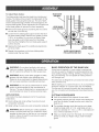
BASIC OPERATION
SAW
This band saw is designed to cut wood and wood compo:
sition products only.
Before starting a cut, watch the saw run. If you experience
excessive vibration or unusual noise, stop immediately.
Turn the saw off, remove the switch key, and unplug the
saw. Do not restart until locating and correcting the problem.
APPLiCATiONS
This product has been designed only for the purposes
listed below:
CUTTmNG PROCEDURES
[] Hold the workpiece firmly against the saw table.
[] Use gentle pressure and both hands when feeding the
work into the blade. Do not force the work; allow the
blade to cut.
[] Scroll cutting and circle cutting of wood and wood
composition products
_
OF THE BAND
Fig. 16
A band saw is basically a "curve cutting" machine that
can also be used for straight-line cutting operations like
cross cutting, ripping, mitering, beveling, compound cut:
ting, and resawing. It is not capable of making inside or
non-through cuts.
WARNING:
Do not use any attachments or accessories not recommended by the manufacturer of
this tool. The use of attachments or accessories not
recommended can result in serious personal injury.
[] Relief cutting of wood and wood composition
L
products
[] The smallest diameter circle that can be cut is determined by blade width. A 1/4 in. wide blade will cut a
minimum diameter of 1-1/2 in.; a 1/8 in. wide blade will
cut a minimum diameter of 1/2 in.
WARNING:
Before starting any cutting operation,
clamp or bolt the band saw to a workbench. Never
operate the band saw on the floor or in a crouched
position. Failure to heed this warning can result in
serious personal injury.
[] Keep your hands away from the blade. Do not handle
pieces so small your fingers will go under the blade
guard.
18
[] Avoidawkwardoperationsandhandpositionswhere
a suddenslipcouldcauseseriousinjuryfromcontact
withtheblade.Neverplacehandsinbladepath.
[] Useextrasupports(tables,sawhorses,blocks,etc.)
whencuttinglarge,small,or awkwardworkpieces.
[] Neverusea personasa substitutefora tableextensionor asadditionalsupportfora workpiece
thatis
longeror widerthanthe basicsawtable.
[] Whencuttingirregularly
shapedworkpieces,
planyour
workso it willnot pinchthe blade.Forexample,a
pieceofmoldingmustlieflatonthesawtable.Workpiecesmustnottwist,rockor slipwhilebeingcut.
Whenbackinguptheworkpiece,
the blademaybindin
thekerf(cut).Thisis usuallycausedbysawdustclogging
thekerforwhenthe bladecomesoutoftheguides.Htfhis
happens:
[] Waituntilthesawhascometo a fullandcomplete
stop.
[] PlacetheswitchintheOFFpositionthenremovethe
switchkeyfromthe switchassembly,.
Storekeyina
safeplace.
[] Unplugthesawfromthe powersource.
[] Wedgethe kerfopenwitha fiatscrewdriver
or wooden
wedge.
[] Openfrontcoverandturntheupperwheelby hand
whilebackingupthe workpiece.
REMOVING
MATERIAL
[] Place the switch in the OFF position, remove the
switch key from the switch assembly.
[] Unplug the saw from the power source before removing jammed material.
AVOmDmNG mNJURY
[] Make sure saw is level and does not rock. Saw should
always be on a firm, leve! surface with plenty of room
for handling and properly supporting the workpiece.
[] Bolt saw to the support surface to prevent slipping,
walking, or sliding during operations like cutting long,
heavy boards.
[] Turn saw off, remove switch key, and unplug cord from
the power source before moving the saw.
[] Do not remove jammed cutoff pieces until blade has
come to a full and complete stop.
[] Choose the right size and style blade for the material
and type of cut you plan to do.
[] Make sure that the blade teeth point down toward the
saw table, that the blade guides, thrust bearings, and
blade tension are properly adjusted, that the blade
guide knob is tight, and that no parts have excessive
play.
[] To avoid accidental blade contact, minimize blade
breakage, and provide maximum blade support, always adjust the blade guide assembly to just clear the
workpiece.
[] Use only recommended accessories.
RELmEF CUTS
Relief cuts are made when an intricate curve (too small a
radius for the blade) is to be cut. Cut through a scrap section of the workpiece to curve in pattern line then carefully
back the blade out. Several relief cuts should be made for
intricate curves before following the pattern line as sections are cutoff of curve "relieving" blade pressure.
SCROLL
JAMMED
Never remove jammed cutoff pieces until the blade has
come to a full and complete stop.
[] With the exception of the workpiece and related support devises, clear everything off the saw table before
turning the saw on.
[] Properly support round materials such as dowel rods
or tubing because they have a tendency to roll during
a cut causing the blade to "bite." To avoid this, always
use a "V" block or clamp workpiece to a miter gauge.
CUTTmNG
For general type scroll cutting, follow the pattern lines by
pushing and turning the workpiece at the same time. Do
not try to turn the workpiece while engaged in the blade
without pushing it, the workpiece could bind or twist the
blade.
[] Before removing loose pieces from the saw table, turn
saw off and wait for all moving parts to stop.
19
BEFORE
LEAVING THE SAW
See Figure 17.
[] Wait until the saw has come to a full and complete
stop.
[] Place the switch in the OFF position, remove the switch
key from the switch assembly. Store key in a safe
place.
[] Unplug the saw from the power source.
[] Make workshop childproof.
[] Lock the shop.
LOCKING
THE SWITCH
See Figure 17.
[] Wait until the saw has come to a full and complete
stop.
Fig. 18
USING THE MITER GAUGE
See Figure 19.
The miter gauge can be turned 45 ° to the right or left.
/
[] Loosen the lock knob on the miter gauge.
[] With the miter gauge in the miter gauge slot, rotate the
gauge unti! the desired angle is reached on the index
scale.
[] Retighten the lock knob.
SWITCH
KEY
Fig. 17
[] Place the switch in the OFF position, remove the switch
key from the switch assembly. Store key in a safe
place.
TiLTiNG
LOCK
KNOB
THE TABLE
MITER
GAUGE
8LOT
See Figure 18.
[] Loosen the table lock handle slightly.
[] Turn the angle adjustment knob, tilting the saw table
toward the front of the saw housing unti! it reaches the
desired angle.
[] Using the scale indicator, check angle markings.
[] Retighten the table lock handle to hold saw table securely
MITEB
GAUGE
in place.
Fig. 19
2O
WARNING:Whenservicing,useonlyidentical
replacement
parts.Useofanyotherpartmaycreate
a hazardorcauseproductdamage.
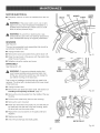
_k
T(RES
Cleaning tires:
[] Pitch and sawdust accumulates on tires and needs to be
removed with a fine wire brush or a piece of wood. Do
not use a sharp knife or any kind of solvent.
WARNING:
Always wear safety goggles or safety
glasses with side sMelds during power tool operation
or when blowing dust. Hfoperation is dusty, also wear
a dust mask.
RepJacing tires:
[] Open front cover and remove saw blade. See section on
hstalling and Adjusting the Blade, page !4.
GENERAL
[] Pry the worn tire away from the wheel carefully.
Avoid using solvents when cleaning plastic parts. Most
plastics are susceptible to damage from various types of
commercial solvents and may be damaged by their use.
Use clean cloths to remove dirt, carbon dust, etc.
[] Stretch the new tire around the wheel.
[] Replace the saw blade and close the front cover.
BLADE
GUmDES
See Figure 20.
_
WAF{NJNG: Do not at any time let brake fluids,
gasoline, petroleum-based products, penetrating
oils, etc. come in contact with plastic parts. Chemicals can damage, weaken or destroy plastic which
may result in serious personal injury.
Blade guides may become rounded and worn during use.
[] Unplug the band saw.
[] Remove the blade guides and file or grind flat.
[] Replace blade guides when filing or grinding has worn
them down and they can no longer be properly secured
in place.
Hthas been found that electric tools are subject to
accelerated wear and possible premature failure when
they are used on fiberglass boats, sports cars, wallboard,
spackling compounds, or piaster. The chips and gdndings
from these materials are highly abrasive to electric too!
parts such as bearings, brushes, commutators, etc.
Consequently, it is not recommended that this too! be
used for extended work on any fiberglass material, wailboard, spackling compounds, or piaster. During any use
on these materials it is extremely important that the tool is
cleaned frequently by blowing with an air jet.
UPPER BLADE
GUIDE SUPPORT
[] Keep your band saw clean.
[] Remove sawdust from the inside frequently.
THRUST
BEARING
SCREW
[] Do not allow pitch to accumulate on the saw table, blade
guides, or thrust bearings. Clean them with gum and pitch
remover.
[] Apply a thin coat of automobile type wax to the saw
table's top so the wood slides easily while cutting.
L
BLADEGU(DES
LUBRICATION
BLADE GUIDE
SUPPORT SCREW
All of the beadngs in this tool are lubricated with a sufficient amount of high grade lubricant for the life of the unit
under normal operating conditions. Therefore, no further
lubrication is required.
BLADE GUARD REMOVED
FOR CLARIFICATIONONLY
WARNING:
To ensure safety and reliability, all
repairs -- with the exception of the externally accessible brushes -- should be performed by a qualified
service technician at a Sears store to avoid risk of
personal injury.
21
Fig. 20
MOTOR/ELECTRmCAL
TiRE
[] Frequently vacuum or blow out sawdust from the motor.
_
WARNING:
Hfthe power cord is worn, cut or damaged in any way, have it replaced immediately by a
qualified service technician. Failure to do so could
result in serious personal injury.
_
WARNING:
To avoid fire or electrocution, reassemble electric parts with only identical replacement
parts. Reassemble exactly as originally assembled.
WASHER
BRUSH
SCREW
LOWER
WHEEL
f
BRUSHES
See Figure 21.
The saw has accessible brush assemblies that should be
periodically checked for wear.
[] Unplug the band saw.
J
[] Remove the screw and washer then pull the brush off.
Fig. 21
[] Place the new brush in the groove with the plastic tabs
under the saw housing.
[] Retighten using the washer and screw.
DRIVE BELT
See Figures
_
22 - 23.
NUT
AND
WASHER
WARNING:
To prevent accidental starting that
could cause possible serious personal injury, turn
off the saw, remove the switch key, and unplug the
saw before working on the band saw.
Due to wear or breakage, the drive belt may need to be
replaced. The drive belt is located behind the lower wheel
of the band saw.
[] Unplug the band saw.
[] Remove the saw blade and set it aside. See section on
hstaiiing
and Adjusting
Fig. 22
the Blade, page 14.
[] Remove the nut and washer from the middle of the saw
housing.
[] Pull the lower wheel away from the saw housing.
[] Remove the worn drive belt.
[] Place new drive belt on the pulley. As you slide the pul=
ley shaft back into the hole in the saw housing, place
the drive belt over the motor pulley.
[] Replace the nut and washer on the pulley shaft and
retighten.
[] Replace saw blade.
DRIVEBELT
[] Check thrust bearings and blade guides.
MOTORPULLEY
Fig. 23
22
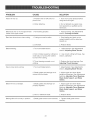
PROBLEM
CAUSE
SOLUTmON
Motor will not run.
1. Problem with On-Off switch or
power cord.
1. Have worn parts replaced before
using band saw again.
2. Motor defective.
2. Do not attempt any repair. Have
tool repaired by a qualified service
technician.
Blade does not run in the approximate
center of the upper wheel,
1. Not tracking properly.
1. Adjust tracking. See Adjustments
section, Tracking the Blade.
Band saw slows down when cutting.
1. Cutting too small a radius.
1. Stop feeding and back up the
material slightly unti! the band saw
speeds up.
2. Dull blade.
2. Replace blade.
1. Too much blade tension.
1. Adjust tension. See Adjustments
section, Adjusting Blade Tension.
2. Kink in blade caused by cutting too
smal! radius or turning the material
too fast when cutting.
2. Use correct cutting technique. See
section, Operation.
3. Thrust bearings scarred or not
rotating.
3. Replace the thrust bearings. See
Adjusting Thrust Bearings.
1. Too much blade tension.
1. Adjust tension. See Adjustments
section, Adjusting Blade Tension.
2. Blade guides and bearings are in
contact with the blade,
2. Adjust upper and lower blade
guides and bearings. See Adjustments
sections, Adjusting Thrust Bearings,
Blade Guide Support, and Blade
Guides.
1. Blade guides and bearings not
properly adjusted,
1. Adjust upper and lower blade
guides and bearings. See Adjustments
sections, Adjusting Thrust Bearings,
Blade Guide Support, and Blade
Guides.
2. Worn or defective blade.
2. Replace blade.
1. Blade guide screws have loosened.
1. Tighten blade guide screws
securely.
Blade breaking.
Saw is noisy when running.
Blade will not cut straight.
Blade guides will not stay in position.
23
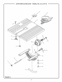
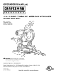
24
CRAFTSMAN
BAND
SAW-
MODEL
NO. 315.214770
._
3
!9
18
17
15
8
FIGURE
A
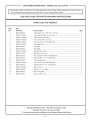
25
_,
CRAFTSMAN
SEE BACK
BAND
SAW-
MODEL
NO. 315.214770
PAGE FOR PARTS ORDERING
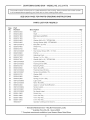
PARTS L_ST FOR F{GURE
Key
No.
_NSTRUCT_ONS
A
Pa_
Number
Description
1
BS90105900
Table (290 mmx
2
089120100014
Throat Plate (38 mmx 38 mm) ..............................................................
1
3
089120100805
Miter Gauge Assembly ..........................................................................
1
4
089120100018
* Hex Screw (M5 x 25 ram) ......................................................................
1
5
089120100026
* Washer (M5 x 9) **STD851005
1
6
089120100019
* Wing Nut (M5) ........................................................................................
1
7
BS90105800
* Nut (M6) .................................................................................................
2
8
BS90108200
* Bolt (M6) .................................................................................................
1
9
089120100900
Qty
290 mmx 22 mm) ......................................................
..............................................................
1
Angle Scale Labe! ..................................................................................
1
10
BS90105100
* Bolt (M6 x 16 ram) ..................................................................................
4
11
BS90105200
* Spring Washer (M6) **STD852006 .........................................................
4
12
BS90105300
13
BS90105400
* Washer (M6 x 12) **STD851006 .............................................................
Trunnion Bracket ....................................................................................
4
1
14
089120100700
15
BS90105500
16
Table Locking Handle Assembly ............................................................
1
* Washer (M10 x 18) **STD851010 ...........................................................
1
089120100025
Bevel Knob .............................................................................................
1
17
BS90108400
Spring (1 x 15 x 28L) ..............................................................................
1
18
BS90108500
* Nylon Nut (M6) .......................................................................................
1
19
BS90107400
* Washer (M6 x 18) ...................................................................................
1
* Standard Hardware item - May Be Purchased Locally
** Available From Div. 98 = Source 980.0
*** Complete
assortment
available
26
at your Nearest Sears Retail Store
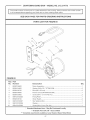
CRAFTSMAN
I
BAND
SAW-
MODEL
NO. 3i5.214770
he model number wil! be found on a pla_e
in a!! correspondence regarding your band saw or when ordering repair parts.
SEE BACK
PAGE FOR PARTS ORDERING
model number
_NSTRUCT_ONS
PARTS UST FOR NGURE
B
1
NGURE
B
Key
No.
Part
Number
1
BS90106800
2
3
B890104800
BS90106700
4
BS90108000
5
6
7
BS90103900
089120100024
BS90108100
8
9
10
Description
Qty
Motor Assembly .........................................................................................
1
Washer (M8 x 22) **STD851008 .................................................................
Bolt (MS x 25 mm) .....................................................................................
2
2
Power Cord (SJP18AWG!3c!6ft)
................................................................
1
*
Screw (M4 x 10 mm Flat Hd.) ....................................................................
Fixing Plate ................................................................................................
Strain Relief ................................................................................................
2
1
2
089120100037
089120100036
*
Star Washer (M4) .......................................................................................
Washer .......................................................................................................
1
1
089120100035
*
Screw (M4 x 6 mm Pan Hd.) ......................................................................
1
*
*
• Standard
Hardware
• * Available
•** Complete
assortment
item - May Be Purchased
From Div. 98 = Source
available
980°0
at your Nearest
27
Locally
Sears Retail Store
CRAFTSMAN
I
BAND
SAW-
MODEL
NO. 3i5.214770
he model number wil! be found on a pla_e
in a!! correspondence regarding your band saw or when ordering repair parts.
SEE BACK
PAGE FOR PARTS ORDERING
PARTS
model number
_NSTRUCT_ONS
UST FOR F_GURE C
11
13
F_GURE C
Key
No.
Part
Number
Description
Qty
1
2
089120100006
BS90102400
* Hex Socket Head Screw (M5 x 8 mm) ..........................................................
Blade Guide ....................................................................................................
2
1
3
BS90101700
Gear ................................................................................................................
1
4
BS90101600
Bracket ...........................................................................................................
1
5
6
BS90101500
BS90101900
* Carriage Bolt (M6 x 66 mm) ...........................................................................
Pin ..................................................................................................................
1
1
Guide (B) .........................................................................................................
1
7
BS90102000
8
089120100032
* Hex Socket Head Screw (M5 x 15 mm) .........................................................
1
9
10
BS90102200
089120100005
Guide (A) .........................................................................................................
* Hex Socket Head Screw (M5 x 12 mm) .........................................................
1
2
11
BS90101800
* Bali Bearing (625ZZ) .......................................................................................
1
12
13
BS90102300
089120100905
Upper or Lower Guide Bracket ......................................................................
No Hands Label .............................................................................................
1
1
14
089120100906
Depth Scale Label ..........................................................................................
1
• Standard
Hardware
• * Available
•** Complete
assortment
item - May Be Purchased
From Div. 98 = Source
available
980°0
at your Nearest
28
Locally
Sears Retail Store
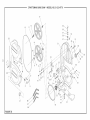
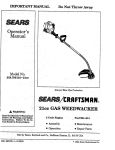
_"
CRAFTSMAN
BAND
SAW - MODEL
NO. 315.214770
12
10
11
12
\
59
51
\
31
62
5O
52
_
_
49
_
48
29
4
4
11
15
47
1\
46
22
\
18 19
65
38
27
42 /
67
66
FIGURE
O
43
44
CRAFTSMAN BAND SAW- MODEL NO. 3i5.214770
pla__e
The model number wil! be found on a
in a!! correspondence regarding your band saw or when ordering repair parts.
SEE BACK
PAGE FOR PARTS ORDERING
PARTS
Key
No.
Part
Number
model number
INSTRUCTIONS
LIST FOR F_GURE D
Description
Qty
1
BS90100100
* Screw (M4 x 8 mm) ................................................................................
9
2
BS90100200
* Washer (M4 x 8) **STD851004 .............................................................
12
3
4
089120100001
089120100002
Hinge ......................................................................................................
Cover ......................................................................................................
2
1
5
BS90100500
* Nut (M3) .................................................................................................
8
6
BS90100600
Retaining Spring ....................................................................................
2
7
BS90100700
Clamp Bracket .......................................................................................
2
8
9
089120100003
089120100004
* Screw (M3 x 6 mm) ................................................................................
Latch ......................................................................................................
8
2
10
BS90101000
*** Blade (1/4 in. x 59=1/4 in. x 0.012 x 6 TPI) .............................................
3
11
BS90101100
Retaining Ring ........................................................................................
2
12
BS90101200
Bali Bearing (6200ZZ) ............................................................................
4
13
14
BS90101300
BS90101400
Upper Wheel ..........................................................................................
Lower Wheel ..........................................................................................
1
1
15
089120100010
* Set Screw (M6 x 15 mm) ........................................................................
3
16
BS90105800
* Nut (M6) **STD840610 ...........................................................................
5
17
089120100028
* Star Washer (M6) ...................................................................................
3
18
089120100011
* Hex Socket Screw (M6 x 45 mm) ..........................................................
1
19
BS90105300
* Washer (M6 x 12) **STD851006 .............................................................
2
20
089120100027
Spring (2 x 14 x 12L) ..............................................................................
1
21
22
BS90103400
BS90103500
Special Washer (6 x 20 x 1.5T) ...............................................................
Shaft .......................................................................................................
1
1
23
BS90103600
Adjusting
Plate .......................................................................................
1
24
BS90103800
Switch (J=9301) ......................................................................................
1
25
26
BS90107000
BS90103700
27
BS90108700
Dust Port Adapter (OD63.5 x OD55 mm) ...............................................
1
28
29
089120100902
BS90104000
Warning Label ........................................................................................
Switch Plate ...........................................................................................
1
1
30
089120100031
* Screw (M4 x 12 mm Pan Hd.) ................................................................
1
31
32
089120100008
BS90104100
Aluminum Housing .................................................................................
Brush ......................................................................................................
1
1
33
BS90104500
Pulley .....................................................................................................
1
34
089120100029
* Screw (M5 x 15 mm Flat Hd.) ................................................................
3
35
BS90104300
Pulley .....................................................................................................
1
* Nut (M4) **STD840407 ...........................................................................
Elastic Pin ..............................................................................................
• Standard Hardware item - May Be Purchased Locally
• * Available From Divo 98 - Source 980.0
•** Complete
assortment
available
at your Nearest
3O
Sears Retail Store
8
1
CRAFTSMAN
I
BAND
SAW-
MODEL
NO. 3i5.214770
he model number wil! be found on a pla_e
in a!! correspondence regarding your band saw or when ordering repair parts.
SEE BACK
PAGE FOR PARTS ORDERING
PARTS
Key
No.
Pa_
Number
model number
_NSTRUCT_ONS
UST FOR F_GURE D
36
BS90104400
Description
Be It .........................................................................................................
Qty
1
37
BS90104600
Shaft .......................................................................................................
1
38
BS90101800
39
BS90101900
Bal! Bearing (625ZZ) ...............................................................................
Pin ...........................................................................................................
1
1
40
BS90104800
*
Washer (M8 x 22) **STD851008 .............................................................
2
41
BS90104900
*
Spring Washer (M8) **STD852008 ..........................................................
2
42
089120100012
*
43
BS90104900
Bolt (M8 x 22 mm) ..................................................................................
Wheel Tire ...............................................................................................
4
2
44
BS90104700
Base ........................................................................................................
1
45
089120100005
46
BS90106900
Hex Socket Screw (M5 x 12 mm) ...........................................................
Pointer ....................................................................................................
5
1
47
089120100021
Adjusting
1
48
BS90107500
Spring (1 x 12 x 18L) ...............................................................................
1
49
BS90107400
Washer (M6 x 18) **STD851006 .............................................................
1
50
089120100020
Lock Knob (M6) ......................................................................................
1
51
089120100022
Tracking Knob (M6) .................................................................................
1
52
BS90103100
Elevating Plate ........................................................................................
1
53
BS90108500
54
089120100023
55
089120100007
56
BS90102700
57
*
*
*
Knob .......................................................................................
Nylon Nut (M6) ........................................................................................
1
Tracking View Window ............................................................................
1
Tension Knob (M6 x 70) ..........................................................................
1
BS90102800
Washer (M6) ............................................................................................
Washer ....................................................................................................
1
2
58
BS90102900
Spring (3 x 24 x 28L) ...............................................................................
1
59
089120100903
Logo Label ..............................................................................................
1
60
089120100030
Nylon Nut (M5) ........................................................................................
3
61
BS90102300
62
089120100904
Upper or Lower Guide Bracket ...............................................................
Tension Label ..........................................................................................
1
1
63
089120100901
Data Plate ...............................................................................................
1
64
089120100905
No Hands Label ......................................................................................
1
65
BS90113800
Switch Key ..............................................................................................
1
66
BS90119800
3 mm Hex Key ........................................................................................
1
67
BS90119900
4 mm Hex Key ........................................................................................
1
68
BS90110000
5 mm Hex Key ........................................................................................
1
983000577
Operator's
1
*
Manual (not shown) .............................................................
* Standard Nardware item - May Be Purchased Locally
** Available From Div. 98 - Source 980.0
*** Complete
assortment
available
at your Nearest
31
Sears Retail Store
Your Home
For repair-in
your home-of all major brand appliances,
lawn and garden equipment, or heating and cooling systems,
no matter who made it, no matter who sold it!
For the replacement parts, accessories and
owner's manuals that you need to do-it-yourself.
For Sears professional installation of home appliances
and items like garage door openers and water heaters.
1-800-4-MY-HOME
Call anytime,
® (1-800-469-4663)
day or night (U.S.A. and Canada)
www.sears.com
www.sears.ca
Our Home
For repair of carry-in items like vacuums, lawn equipment,
and electronics, call or go on-line for the location of your nearest
Sears Parts & Repair Center.
1-800-488-1222
Call anytime,
day or night (U.S.A. only)
www.sears.com
To purchase a protection agreement (U.S.A.)
or maintenance agreement (Canada) on a product serviced
1-800-827-6655
(U.S.A.)
Para pedir servicio de reparaci6n
1-800-361-6665
Au Canada
a domicilio, y para ordenar piezas.
1-888-SU-HOGAR sM
....
Trademark
/ TivlTrademark
/ SMService
(Canada)
pour service en frangais:
1 -800- LE- FOYER Mc
( 1- 800_533_6937)
(1-888-784-6427)
® Registered
by Sears:
www.sears.ca
Mark of Sears,
Roebuck
® Marca Registrada / TM Marca de F&brica / SMMarca de Servicio de Sears,
MC Marque de commerce / MDMarque d_posCe de Sears, Roebuck and Co.
and Co.
Roebuck
and Co.
® Sears,
Roebuck
and Co.