1
USER MANUAL
uSign™
Signature Capture Module
Models uSign 100 & uSign 200
80084501-001-A
04-24-2007
uSign User Manual
FCC WARNING STATEMENT
This equipment has been tested and found to comply with the limits for a Class B digital
device, pursuant to Part 15 of FCC Rules. These limits are designed to provide
reasonable protection against harmful interference when the equipment is operated in a
commercial environment. This equipment generates, uses, and can radiate radio
frequency energy and, if not installed and used in accordance with the instruction
manual, may cause harmful interference to radio communications.
FCC COMPLIANCE STATEMENT
This device complies with Part 15 of the FCC Rules. Operation of this device is subject
to the following conditions: this device may not cause harmful interference and this
device must accept any interference received, including interference that may cause
undesired operation.
CANADIAN DOC STATEMENT
This digital apparatus does not exceed the Class B limits for radio noise for digital
apparatus set out in the Radio Interference Regulations of the Canadian Department of
Communications.
Le présent appareil numérique n’émet pas de bruits radioélectriques dépassant les
limites applicables aux appareils numériques de las classe B prescrites dans le
Réglement sur le brouillage radioélectrique édicté par les ministère des
Communications du Canada.
CE STANDARDS
An independent laboratory performed testing for compliance to CE requirements. The
unit under test was found compliant to Class B.
ID TECH is a registered trademark of International Technologies & Systems
Corporation. uSign, and Value through Innovation are trademarks of International
Technologies & Systems Corporation.
USB (Universal Serial Bus) Specification is Copyright by Compaq Computer
Corporation, Intel Corporation, Microsoft Corporation, and NEC Corporation. Windows,
Excel, & Notepad are registered trademarks of Microsoft Corporation.
Copyright © 2006, International Technologies & Systems Corp. All rights reserved.
Page 2 of 18
uSign User Manual
LIMITED WARRANTY
ID TECH warrants to the original purchaser for a period of 12 months from the date of
invoice that this product is in good working order and free from defects in material and
workmanship under normal use and service. ID TECH’s obligation under this warranty
is limited to, at its option, replacing, repairing, or giving credit for any product which has,
within the warranty period, been returned to the factory of origin, transportation charges
and insurance prepaid, and which is, after examination, disclosed to ID TECH’s
satisfaction to be thus defective. The expense of removal and reinstallation of any item
or items of equipment is not included in this warranty. No person, firm, or corporation is
authorized to assume for ID TECH any other liabilities in connection with the sales of
any product. In no event shall ID TECH be liable for any special, incidental or
consequential damages to purchaser or any third party caused by any defective item of
equipment, whether that defect is warranted against or not. Purchaser’s sole and
exclusive remedy for defective equipment, which does not conform to the requirements
of sales, is to have such equipment replaced or repaired by ID TECH. For limited
warranty service during the warranty period, please contact ID TECH to obtain a Return
Material Authorization (RMA) number & instructions for returning the product.
THIS WARRANTY IS IN LIEU OF ALL OTHER WARRANTIES OF
MERCHANTABILITY OR FITNESS FOR PARTICULAR PURPOSE. THERE ARE NO
OTHER WARRANTIES OR GUARANTEES, EXPRESS OR IMPLIED, OTHER THAN
THOSE HEREIN STATED. THIS PRODUCT IS SOLD AS IS. IN NO EVENT SHALL
ID TECH BE LIABLE FOR CLAIMS BASED UPON BREACH OF EXPRESS OR
IMPLIED WARRANTY OF NEGLIGENCE OF ANY OTHER DAMAGES WHETHER
DIRECT, IMMEDIATE, FORESEEABLE, CONSEQUENTIAL OR SPECIAL OR FOR
ANY EXPENSE INCURRED BY REASON OF THE USE OR MISUSE, SALE OR
FABRICATIONS OF PRODUCTS WHICH DO NOT CONFORM TO THE TERMS AND
CONDITIONS OF THE CONTRACT.
The information contained herein is provided to the user as a convenience. While every
effort has been made to ensure accuracy, ID TECH is not responsible for damages that
might occur because of errors or omissions, including any loss of profit or other
commercial damage, nor for any infringements or patents or other rights of third parties
that may result from its use. The specifications described herein were current at the
time of publication, but are subject to change at any time without prior notice.
ID TECH
10721 Walker Street
Cypress, CA 90630
(714) 761-6368
www.idtechproducts.com
Copyright © 2006, International Technologies & Systems Corp. All rights reserved.
Page 3 of 18
uSign User Manual
Table of Contents
1.0
Introduction.................................................................................................6
2.0
Features .....................................................................................................6
3.0
Model Designations ....................................................................................7
4.0
Installing uSign ...........................................................................................7
4.1
Communication Interface ........................................................................8
4.2
USB-CDC Setup ...................................................................................10
5.0
Terms & Abbreviations ...............................................................................7
6.0
Specifications ...........................................................................................10
6.1
Power requirement................................................................................10
6.2
Physical housing uSign 100 ..................................................................10
6.3
Physical housing uSign 200 ..................................................................11
6.4
LCD screen & Resistive touch pad .......................................................11
6.5
Communication interface ......................................................................11
6.6
LED.......................................................................................................11
6.7
Agency Approvals .................................................................................11
6.8
Electronics MTBF..................................................................................11
6.9
Electro-Static Discharges (ESD) ...........................................................11
6.10 Environmental .......................................................................................11
7.0
uSign commands description....................................................................13
7.1
Command protocol:...............................................................................13
7.2
System Commands...............................................................................13
7.2.1
Get firmware version......................................................................13
7.2.2
Get serial number ..........................................................................13
7.2.3
Get clip area ..................................................................................13
7.2.4
Set clip area...................................................................................13
7.2.5
Clear clip area................................................................................13
7.3
One byte commands.............................................................................14
7.3.1
Stop Capturing...............................................................................14
7.3.2
Start Capturing use FBP format 1..................................................14
7.3.3
Start Capturing use FBP format 2..................................................14
7.3.4
Turn red led on ..............................................................................14
7.3.5
Turn red led off ..............................................................................14
7.3.6
Clear CMP format mode data ........................................................14
7.3.7
Get data 0x00 ................................................................................14
7.3.8
Start Capturing use CMP format....................................................14
7.3.9
Reset points counter ......................................................................14
7.3.10 Get point counter high byte............................................................14
7.3.11 Get point counter low byte .............................................................14
7.3.12 Start Capturing use FBP format 0..................................................15
7.4
Multi-byte commands............................................................................15
7.4.1
Initialize device ..............................................................................15
7.4.2
Get PW120 Version .......................................................................15
7.4.3
Test device ....................................................................................15
7.4.4
Set CTS control .............................................................................15
7.4.5
Set interval between two points .....................................................15
Copyright © 2006, International Technologies & Systems Corp. All rights reserved.
Page 4 of 18
uSign User Manual
7.4.6
7.4.7
7.4.8
7.4.9
7.4.10
7.4.11
7.4.12
7.4.13
7.4.14
7.4.15
7.4.16
7.4.17
Get data 0x00 0x01 .......................................................................15
Calibrate the device .......................................................................15
Set offset position ..........................................................................15
Get data 0x01 ................................................................................15
Offset using control ........................................................................15
Stop Capturing...............................................................................16
Start Capturing use FBP format 1..................................................16
Clear display screen ......................................................................16
Draw line........................................................................................16
Draw hollow rectangle....................................................................16
Draw solid rectangle ......................................................................16
Draw text........................................................................................16
Table of Figures
Figure 1
Figure 2
Figure 3
Figure 4
Figure 5
New Hardware Wizard opening window.............................. 9
Browse for File ................................................................... 9
Installation Warning Message........................................... 10
Outline Drawing for uSign 100 .......................................... 17
Outline Drawing for uSign 200 .......................................... 18
Copyright © 2006, International Technologies & Systems Corp. All rights reserved.
Page 5 of 18
uSign User Manual
1.0
Introduction
The use of electronically captured signatures has become common for Point of Service
(POS) applications. Electronic signature capture reduces transaction time, eliminates
sorting & sending paper, provides convenient electronic storage & transmission, and
gives legal accountability (non-repudiation) for POS transactions.
uSign™ is an electronic signature capture device with a back lighted graphic LCD
display and touch sensitive screen that is the signature panel. Authors can view their
signatures in real time during the signing process. Signatures are compressed and
provided to a Host system for signature & data storage. The LCD display allows for
interactive text, which supports pen-tap commands and function selections. The
interactive Host operations allow selections and navigations through transactions with
just the stylus.
The LCD & touch sensitive screen are surrounded in a plastic housing. The housing
provides a tethered non-electronic stylus. The stylus is fastened to the housing in a way
to allow stylus replacement. A mounting plate secures the uSign housing to a counter
top or other mounting surface. An overlay covers and protects the signature area of the
uSign display. The overlay is removable allowing replacement if the signature area
becomes worn from stylus use. Customer specific front overlay designs are possible as
needed by an application.
There are two major uSign housing configurations. The first is a signature pad enclosed
in a stylish housing. This uSign is a POS System level product intended for signature
capture at a transaction counter. A convenient palm rest area below the signature
panel provides support during the signing process. The second configuration is an
OEM version with a smaller housing and intended for mounting to a vertical or near
vertical surface. Both products have the same internal components and operations.
2.0
Features
Electronic signature capture w Buffered signature capability
Sampling rate up to 190 dots per second
Real time signature capture with 5:1 compression
Raw data output available
Algorithms to filter spikes, provide Smoothing, & Calibration algorithms
Command & response driven operations through an API
Graphic display of signature during capture
Display graphics under Host control when not in signature process
Touch pad dot position matches LCD pixel locations
Operates with Windows 2000, XP, and Vista operating systems
Replaceable non-active tethered stylus
Resistive touch pad with transparent, replaceable protective overlay
The uSign 100 is UL listed; both uSign 100 & uSign 200 are RoHS compliant.
Copyright © 2006, International Technologies & Systems Corp. All rights reserved.
Page 6 of 18
uSign User Manual
3.0
Model Designations
uSign 100
uSign 200
IDUA-01x100 *
IDUA-01x500 *
* The “x” defines the communication interface, 2 = RS232 and 6 = USB-CDC.
4.0
Terms & Abbreviations
COM
Host
LCD
LED
mA
RS232
USB
VDC
5.0
Host communication port
Personal Computer, Terminal, or similar device
Liquid Crystal Display
Light Emitting Diode
Milli-Amperes of electrical current
Serial communications
Universal Serial Bus, serial communications
Volts Direct Current
Installing uSign
uSign is designed for an indoor environment. Locate the uSign where it is convenient to
operate and protected from heat or direct sunlight. Position the uSign so the signature
pad area is easy to reach and the immediate area is clear for authoring the signature.
The uSign housing has threaded inserts in the bottom and relief areas for hook & loop
fasteners. A metal mounting bracket with keyhole & screw mounting is mounted to the
back of the housing.
The uSign 100 with an RS232 interface uses a standard DB25 connector and is
supplied power with a 9VDC power adaptor. The uSign 200 with an RS232 interface
uses a standard DB9 connector and uses a 5VDC power adaptor. The input voltage on
the power adaptors may be limited; do not exceed the input voltage rating of the power
adaptor. Connect the power adaptor after the other connections are made. The uSign
having a USB communication interface receives power from the host through the USB
port.
For both interface types and when power is applied, the green & red LED on the uSign
are on for a moment, go off, and then the green is on and flashing. If the LED does not
light, check the connections and the availability of power from the power outlet. With
the green LED flashing, the LCD screen displays: “IDTECH uSign, Version x.xx.” When
the signature screen is touched or commands are received from a Host, the LED is
turned off and the screen is cleared for Host operations. The Green LED is controlled
and is on when uSign is in the capture mode; the red LED is host controlled.
The communication type can be RS232 or USB-CDC. Use the Communication
Interface section that corresponds with the interface of your uSign unit.
Copyright © 2006, International Technologies & Systems Corp. All rights reserved.
Page 7 of 18
uSign User Manual
5.1
Communication Interfaces
RS232
The uSign has a communication cable with a DB25 (100 Model) or DB-9 (200 Model)
connector that fits the computer serial (RS232) COM port connection. See the
Specifications, Interface Section for COM port settings.
Connect the RS232 connector to the PC and insure it is fully seated into the connector.
Connect the power adaptor output to the power input socket on the back of the DB
connector shell. Connect the power adaptor to the AC line power outlet.
USB
The USB interface is a Communication Device Class that opens a virtual COM Port,
which operates as though the COM was an RS232 device. The USB communication
uses the Windows USB-CDC driver included in Windows 2000 & XP operating systems.
ID TECH provides an INF file for use with the CDC driver. Note: Windows XP with
Service Pack 1 can cause intermittent problems; use Service Pack 2.
Connect the USB connector to the PC and insure it is fully seated into the jack. If the
LEDs do not light, check the connections and the availability of power from the Host.
When the USB connection is recognized by the operating system for the first time, a
Found New Hardware message is given. The operating system must install the uSign
INF setup file, {uSignUsbCDC.inf} for the system to communicate with the uSign.
Retrieve the uSignUsbCDC.inf and companion usbser.sys files from the ID TECH
website and save the files in a convenient location on the PC system.
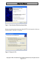
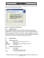
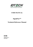
The New Hardware Wizard window appears. Follow the directions and the wizard
properly installs the INF setup information into the operating system. Select the “No,
not this time” button and Click Next > to continue. Then select the “Install from a list or
specific location (advanced)” button and Click Next > to continue.
Copyright © 2006, International Technologies & Systems Corp. All rights reserved.
Page 8 of 18
uSign User Manual
Figure 1 New Hardware Wizard opening window
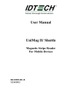
Browse and select the folder where the uSignUsbCDC.inf and companion usbser.sys
files are located. Click Next > to continue.
Figure 2 Browse for File
Copyright © 2006, International Technologies & Systems Corp. All rights reserved.
Page 9 of 18
uSign User Manual
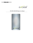
There is a warning window that the INF file is not registered; Click “Continue Anyway”.
Click Finish to complete the INF installation.
Figure 3 Installation Warning Message
5.2
USB-CDC Setup
The following steps provide a check on the USB-CDC COM port selected by the
operating system. This step is used only if there is a need to confirm operation and
possible to review the communication port number. Open the Windows Control Panel
and follow the selections: System, Hardware Tab, and Device Manager. Expand the
Port (COM & LPT) folder. There should be an item “IDTECH USB-RS232 uSign (COM
#)”, where # is a Port number. uSign is set-up and communicating.
6.0
Specifications
6.1
Power requirement
Voltage
Current
RS232 Power
USB Power
6.2
Physical housing uSign 100
Overall size
Display
uSign 100 is 9VDC and uSign 200 is 5VDC
150mA typical
AC adapter, center positive adaptor plug output
Host USB port
113mm wide
77.5mm high
31.5mm thick including back plate
3.3-inch diagonal signature area
Copyright © 2006, International Technologies & Systems Corp. All rights reserved.
Page 10 of 18
uSign User Manual
6.3
Physical housing uSign 200
Overall size
Display
6.4
129mm wide (5.1 in)
146mm length (5.75 in)
40mm thick including back plate (1.57 in)
3.3-inch diagonal signature area
LCD screen & Resistive touch pad
Touchpad
Display
Sampling Rate
Touchpad Resolution
Display Resolution
Overlay Screen
6.5
Communication interface
RS232
Baud rates
Default
USB
6.6
Resistive, transparent, pressure-sensitive screen
STN monochrome LCD
Up to 190 samples per second
up to 929 dpi
LCD Resolution: 192 x 64 dots
Removable/Field replaceable signature surface
1200 to 115200
9600 baud, data bits – 8, Parity – none, Stop bit – 1
2.0 Full Speed (Common Device Class)
LED
Two individual LEDs (one green & one red)
Signature Pad or Host controlled
6.7
Agency Approvals
FCC Class B, & CE,
The uSign 100 is UL Listed
The product is RoHS compliant.
6.8
Electronics MTBF
Electronics MTBF
6.9
200,000 POH, based on Bellcore standard.
Electro-Static Discharges (ESD)
The electronics must survive ESD of 4kV contact, and 8kV air discharge. Meets or
exceeds IEC 1000-4-2.
6.10
Environmental
Temperature ranges
Operating
1 to 45 C
Storage (sealed container) -10 to 70 C
Relative humidity
(34 to 113 F)
(14 to 158 F)
Copyright © 2006, International Technologies & Systems Corp. All rights reserved.
Page 11 of 18
uSign User Manual
10% to 95% non-condensing
Copyright © 2006, International Technologies & Systems Corp. All rights reserved.
Page 12 of 18
uSign User Manual
7.0
uSign commands description
(Version: 0.02 Date: 2007-03-19) Note: digits are given in little-endian format.
7.1
Command protocol:
Host to device: STX LenL LenH CommandData Lrc1 Lrc2 ETX
STX: 0x02. 1 byte.
LenL+LenH: sizeof(CommandData). 2 bytes.
CommandData: main command string. Several bytes needed.
Lrc1: Exclusive or of CommandData. 1 byte.
Lrc2: Sum of CommandData. 1 byte.
ETX: 0x03. 1 byte.
Device to Host: STX LenL LenH ResponseData Lrc1 Lrc2 ETX
STX: 0x02. 1 byte.
LenL+LenH: sizeof(ResponseData). 2 bytes.
ResponseData: main response string. Several bytes needed.
Lrc1: Exclusive or of ResponseData. 1 byte.
Lrc2: Sum of ResponseData. 1 byte.
ETX: 0x03. 1 byte
7.2
System Commands
7.2.1
Get firmware version
Command string: 78 01
Response string: IDTECH-USIGN V0.02
7.2.2
Get serial number
Command string: 78 02
Response string: Serial number
7.2.3
Get clip area
Command string: 7A 04 01
Response string: Clip area data (8 bytes)
Clip area is a rectangle coded as: left (2 bytes) + top (2 bytes) + right (2 bytes) + bottom
(2 bytes)
7.2.4
Set clip area
Command string: 7A 04 02 Clip area data( 8 bytes)
Response string: 0xE0
7.2.5
Clear clip area
Command string: 7A 08
Response string: 0xE0
Copyright © 2006, International Technologies & Systems Corp. All rights reserved.
Page 13 of 18
uSign User Manual
7.3
One byte commands
7.3.1
Stop Capturing
Command string: C0
Response string: C0
7.3.2
Start Capturing use FBP format 1
Command string: C1
Response string: C1
7.3.3
Start Capturing use FBP format 2
Command string: C2
Response string: C2
7.3.4
Turn red led on
Command string: C3
Response string: C3
7.3.5
Turn red led off
Command string: C4
Response string: C4
7.3.6
Clear CMP format mode data
Command string: C5
Response string: C5
7.3.7
Get data 0x00
Command string: C6 or D4 or D5
Response string: 00
7.3.8
Start Capturing use CMP format
Command string: C7
Response string: C7
7.3.9
Reset points counter
Command string: D0
Response string: D0
7.3.10
Get point counter high byte
Command string: D1
Response string: D1
7.3.11
Get point counter low byte
Command string: D2
Response string: D2
Copyright © 2006, International Technologies & Systems Corp. All rights reserved.
Page 14 of 18
uSign User Manual
7.3.12
Start Capturing use FBP format 0
Command string: D6
Response string: D6
7.4
Multi-byte commands
7.4.1
Initialize device
Command string: 28 10 00 00
Response string: DC 05
7.4.2
Get PW120 Version
Command string: 2A 10 00 00
Response string: 01 00
7.4.3
Test device
Command string: 52 12 00 00
Response string: 52 12
7.4.4
Set CTS control
Command string: 22 15 01 00 01(enable)/00(disable)
Response string: 01
7.4.5
Set interval between two points
Command string: 28 15 01 00 xx
Response string: 01
7.4.6
Get data 0x00 0x01
Command string: 2A 15 00 00
Response string: 00 01
7.4.7
Calibrate the device
Command string: 30 15 00 00
Response string: 01
7.4.8
Set offset position
Command string: 31 15 04 00 xx xx xx xx(offset point)
Response string: 01
7.4.9
Get data 0x01
Command string: 32 15 00 00
Response string: 01
7.4.10
Offset using control
Command string: 34 15 01 00 01(enable)/00(disable)
Response string: 01
Copyright © 2006, International Technologies & Systems Corp. All rights reserved.
Page 15 of 18
uSign User Manual
7.4.11
Stop Capturing
Command string: 40 30 00 00
Response string:
7.4.12
Start Capturing use FBP format 1
Command string: 41 30 00 00
Response string:
7.4.13
Clear display screen
Command string: 40 32 00 00
Response string:
7.4.14
Draw line
Command string: 43 32 08 00 X1(2 bytes) Y1(2 bytes) X2(2 bytes) Y2(2 bytes)
Response string:
Line is defined by two points: (x1,y1) --- (x2,y2)
7.4.15
Draw hollow rectangle
Command string: 50 32 08 00 Left(2 bytes) Top(2 bytes) Right(2 bytes) Bottom(2 bytes)
Response string:
7.4.16
Draw solid rectangle
Command string: 51 32 08 00 Left(2 bytes) Top(2 bytes) Right(2 bytes) Bottom(2 bytes)
Response string:
7.4.17
Draw text
Command string: 80 32 (String Length+6) 00 X position(2 bytes) Y position(2 bytes)
String Length(2 bytes) String
Response string:
Copyright © 2006, International Technologies & Systems Corp. All rights reserved.
Page 16 of 18
uSign User Manual
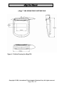
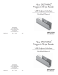
uSign™ 100 SIGNATURE CAPTURE PAD
Figure 4 Outline Drawing for uSign 100
Copyright © 2006, International Technologies & Systems Corp. All rights reserved.
Page 17 of 18
uSign User Manual
uSign™ 200 SIGNATURE CAPTURE PAD
Figure 5 Outline Drawing for uSign 200
Copyright © 2006, International Technologies & Systems Corp. All rights reserved.
Page 18 of 18