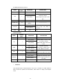
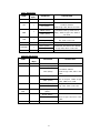
1
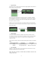
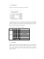
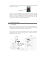
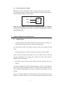
ENGLISH ONE-900 UHF RFID Reader User Manual TABLE OF CONTENTS 1. 1.1 1.2 1.3 1.4 1.5 THINGS TO START FROM................................................................ 1 Functions & Applications.............................................................. 1 Appearance Navigator................................................................... 1 Compliant Tags.............................................................................. 2 What Is In The Box......................................................................... 2 Other Accessories ......................................................................... 3 2. 2.1 2.2 2.3 2.4 QUICK CONFIGURATION GUIDE..................................................... 3 Start to Read .................................................................................. 3 Setup Frequency ........................................................................... 5 Data Upload.................................................................................... 5 Adjust Reading Ranges ................................................................ 6 3. QUICK INSTALLATION GUIDE......................................................... 7 3.1 Mount Reader................................................................................. 7 3.2 Control Peripherals via GPIOs ..................................................... 8 4. TROUBLE SHOORTING AND MAINTENANCE................................ 8 4.1 Troubleshooting ............................................................................ 8 4.2 Maintenance................................................................................... 9 5. SUPPLEMENTARY............................................................................ 9 5.1 Technical Specifications ............................................................... 9 5.2 Warranty ......................................................................................... 9 6. COMMUNICATION PROTOCOLS AND DATA FORMATS............. 10 6.1 Wiegand........................................................................................ 10 Output Waveform ..................................................................... 10 Data Formats............................................................................. 10 6.2 RS485.............................................................................................11 Upload ........................................................................................11 Download .................................................................................. 12 1. THINGS TO START FROM 1.1 Functions & Applications ONE-900 long range reader is a high performance integrated reader. It can read EPC G2 C1 passive tags at up to 10m, but with moderate size and weight. The reader is unique at working with not only EPC G2 C1 passive tags, but also our BGC series 2.4GHz active tags. The reader aims at providing an efficient and cost-effective solution for automatic vehicle identification. The dual-frequency reader resolves reading problems through car window tint/film by using active tags; also it enables most clients to use the lower cost passive tags. 1.2 Appearance Navigator Front View Back View Label Stud, Gasket, and Nuts for Mounting Removable Cover Status LEDs: 1 Red, 4 Blue Bottom View Power Interface Indicators Communication Interfaces, GPIOs 2.4G and 900M Settings -1- 1.3 Compliant Tags ONE-900 can read both standard EPC G2 C1 passive tags and our BGC series active tags. Notes: The manufacturer is not liable for ensuring reading results and compliance of the reader with tags from other suppliers. The manufacturer supplies the following tag models: Passive Tags (EPC G2 C1/ISO18000-6C) BMC-G2C-01 Active Tags BGC-S BGC-04 BGC-K Each model has several sub-models (e.g. BGC-04-12, BGC-04-70), which provides different reading distances when working with a reader. Please refer to our Active Tag Selection and Installation Guide to choose a suitable tag model. 1.4 What Is In The Box Reader CD 12V/5A (DC) Power Adaptor Please check the completeness of the standard accessories when the reader arrives. 2 1.5 Other Accessories Clients can fix a on their sites in any way they may see fit. Also clients are recommended to order a standard pole mounted bracket from the manufacturer to install the reader. Below is our mounted bracket. Parts 2. After Assembly QUICK CONFIGURATION GUIDE 2.1 Start to Read ONE-900 can work on three reading modes. By factory default, once a ONE-900 is connected to the appropriate power supply, it will begin to read tags continuously. Also the reader can be triggered to read by a loop detector or infrared detector. As shown on the left, clients can switch between constant and trigger mode easily on the reader’s panel. Notes: after switching the reading mode, the reader should restart to make the change takes effect. Otherwise, clients can also program the interrogator to read in response to commands. 3 Trigger Reading To enable this mode, the reader needs to be wired to a trigger (typically a loop detector or infrared detector) via its general inputs. There are two pairs of signal inputs on the reader: IN1+/IN1-, and IN2+/IN2-. Only IN1 ports are applicable for this function. For testing purposes, you may short IN1+ with IN1-, which will generate a valid trigger signal. Notes: when trigger signals varnish, ONE-900 will continue to read for 2 seconds. Installers can pull out the terminal blocks on the reader’s interfaces for easy wiring with external devices, and then insert back the terminal blocks to complete connection with the reader (shown below). Pull out terminal blocks Command Mode In this mode, ONE-900 will remain on standby until it receives a command from PC. For example, the PC sent a read command to a ONE-900, and then the reader will start to read and make a return to the PC. The command mode is to facilitate clients to integrate the reader. When a reader is working, it should emit LED and audio signals according to its operation status. Reader Operation Status LED Signals Audio Signals Standby Red Light Constant On No Reading Blue Light Keeps Flash Beep Once for Each Read Turn On/Off 2.4G ONE-900 is a hybrid reader. But the 2.4G reading function can be turned on or off by pushing the toggle switch 2 on the reader’s panel. Notes: after push the switch, the reader should be restarted to allow the new settings to take effect. 4 2.2 Setup Frequency ONE-900 can operate on either fixed frequency or FHSS mode. As shown above, switch 3, 6, 7, and 8 on the reader’s panel is to set the operating frequency of the reader. There are eight frequency channels available on the reader. It can be set to operate on any of the channels or automatically hops between channels. By default, the reader should operate on 922.625MHz. Chart: Frequency Channels Settings of ONE-900 Switch Position 3 6 7 8 Operating Frequency 1 0 0 0 920.625 MHz 1 0 0 1 921.125 MHz 1 0 1 0 921.625 MHz 1 0 1 1 922.125 MHz 1 1 0 0 922.625 MHz 1 1 0 1 923.125 MHz 1 1 1 0 923.625 MHz 1 1 1 1 0 2.3 Any 924.125 MHz Auto-hop between Channels Transmit Data ONE-900 can transmit data to a controller via wiegand (26/34), or to a PC via RS232 or RS485 interface. By default, ONE-900 should upload data via wiegand 26. Clients can set to use other interfaces in the example software provided by the manufacturer. Once the settings have been saved to the reader, the reader should be restarted to activate the settings. 5 Wiegand 26 There are clear interface definitions on the reader’s panel to enable connection with a controller. Wiegand 34 There are clear interface definitions on the reader’s panel to enable connection with a controller. RS232 If the reader is set to transmit data via RS232, it will upload data actively to an external device when it reads a tag. RS485 The reader can be set to upload data actively or passively via RS232 to external devices. With built-in RS485 protocols, a reader can connect to a controller or PC directly. Also multiple readers can be used to build a network. For more details about protocols and data formats, please refer to part 6. Please note that the maximum data transmission distances of the interfaces are different. Interface Maximum Data Devices Can Be Connected Transmission Distance Wiegand (26/34) 100m Controller RS232 10m PC RS485 1000m Controller, PC 2.4 Adjust Reading Ranges A standard ONE-900 reader can work with both EPC G2 C1 passive tags and active tags. With a passive tag, its reading range can be up to 10m, depending on tags and/or change the output power of the antenna. Its reading distances are more flexible on active tags. As there are more tag models selectable, also clients can adjust the ranges for 2.4G on the hardware easily. Below are further explanations on setting the reading ranges for 2.4G active tags. As mentioned in 1.3, each of our major active tag models has several sub-models, shown by suffix e.g. -12, -70. These sub-models enable a reader to have variable minimum and maximum adjustable ranges. For example, to present both BGC-S-12 and BGC-S-70 tags in front of a BG-245-K, the min. adjustable range for BGC-S-12, should be around 3-5m, while the min. adjustable range for BGC-S-40 can reach 20-30m. The maximum adjustable range on a -12 tag can be 15-20m, while on a -40 tag, it can make 40m and more. For parking applications, however, -12 series tags should fit for most systems. 6 On the same tag, clients can still set different reading ranges by rotating the embedded potentiometer in the reader. Potentiometer Clients can use a small screwdriver to rotate the potentiometer clockwise or counter clockwise, accordingly the reading range becomes longer or shorter. At the adjustable extreme, you can hear a low spring-like sound, after that, further rotation in the same direction would not change the reading range any more. There are around five valid rounds between the minimum and maximum adjustable position. 3. QUICK INSTALLATION GUIDE 3.1 Mount Reader ONE-900 can be mounted on either a pole or wall. The reader is equipped with a linear horizontal antenna with limited readable angle. It should be installed at a suitable height and angle towards the ground, so as to give the optimal performance. A series of factors can affect the reader installation height and angles, including the reading distance, width of the lane, types of vehicles, etc. The figure below shows a typical installation for your reference. 4m 15º-20º 50cm About 1.8m from the middle of the reader to the ground 7 30º-40º 3.2 Control Peripherals via GPIOs ONE-900 has 1 pair of relay outputs. Clients can program the reader to send close or open signals to the contact point when it reads a valid tag. In this way the reader is able to control a peripheral directly, e.g. barrier, alarm. OUT + Close OUT - Open Notes: the relay output can only control an equipment powered by maximum 110V/0.5A AC or 24V/1A DC power supply. To control a 220V equipment, an external relay should be used. 4. TROUBLE SHOORTING AND MAINTENANCE 4.1 Troubleshooting I push the switches on the reader but it does not work. Why is that? For example, I’ve switched off the 2.4G function, but it continues to read active tags. You must restart the reader after pushing a switch, so that the new settings can take effects. Why the blue LEDs on my reader never flash and the reader cannot read tags? Please check with its reading mode settings. Only at the constant mode, the reader will read tags automatically. At the trigger mode, however, the reader should receive a triggering signal to start reading. My reader can hardly read a tag or the distance shorter than expected, what is the reason? The reader is equipped with a linear horizontal polarization antenna. So tags should be placed in a way where its polarization direction is in line with that of the reader’s antenna. If you consider the reading ranges not so well on a tag, please rotate the tag by 90º and try again. Also in one of following situations, the reading distance can be shortened even there is no problem on the reader: tags are close to or have direct contact with human body, metal 8 screen, or liquid obstruct between reader and tags. Why the reading distance of my reader on windshield tags is so short in the open air? Windshield tags, as the name suggested, should be attached on window so as to get optimal reading effects. For simulation, you can fix a tag on a piece of glass with crystal tapes, and try again with the reader. 4.2 Maintenance There are a few tips to get the optimal performance out of the reader. Always use the power adaptor provided by the manufacturer, or consult the supplier for a compliant power adaptor from a third source. DO NOT disassemble the reader. If there is any problem on the device, please return the supplier for repairing. 5. SUPPLEMENTARY 5.1 Technical Specifications 5.2 Warranty Device Model ONE-900 Operating Frequency 920.5-924.5MHz and/or 2.4GHz Compliant Tags EPC G2 C1/ISO-18000-6C/BGC series Reading Range Passive tag: up to 10m Active Tag: depending on tags & adjustment Operating Mode Constant, trigger, command Antenna 1 integrated, linear horizontal Moving Tag Detection ≤40Km/h GPIOs 1 photo coupler input, 1 relay output Communication Interfaces Wiegand (26/34), RS232, RS485 Power Supply Operating Temperature Storage Temperature Humidity DC 12V, 5A -20℃ ~ +65℃ -40℃ ~ +85℃ 0 ~ 95% Environmental Sealing IP65, DC ground lightening proof Housing Size & Weight FRP + stain resistant aluminum 460×260×110mm , 3kg Memory No Please refer to the warranty policy for detailed terms and conditions. 9 6. COMMUNICATION PROTOCOLS AND DATA FORMATS Here we’ll explain further about the protocols that clients can use on a ONE-900 for data transmission and relevant data formats. 6.1 Wiegand Wiegand protocols are used to connect a reader with a wiegand controller. This interface supports one-way data transmission, namely, the reader can send data to the controller, but cannot receive data via wiegand ports. Wiegand interface contains two data lines and one ground line. For any binary data, e.g. 01010101B, the protocols send out 0 or 1 in separate lines. That is to say, the W0 line sends 0 only, and the W1 always sends 1. According to the data bits transmitted per frame, wiegand protocols have two types: wiegand 26 and wiegand 34. To ensure a controller to receive data via wiegand, the ground line of the reader should always be connected to the ground port of the controller, or the negative electrode of the power supply of the reader. Output Waveform The default pulse width time is 100us, pulse interval time is 1.0ms, and frame interval is no less than 800ms.The output waveforms can be changed in software. Data Formats Wiegand 26 This protocol transmits 26-bits data per frame, and only 24 bits among which are valid data. We define the 24 bits to correspond to the last three bytes of a tag ID. Details are as below: WIEGAND OUTPUT Bit0 PURPOSE Even Parity over Bit1 - Bit12 Bit1 - Bit12 ID[5] Bit13 - Bit24 ID[6] Notes: ID 5~7 equals to the last three bytes of a tag ID. 10 ID [7] Bit25 Odd Parity over Bit13 - Bit24 Wiegand 34 This protocol transmits 34-bits data per frame, and only 32 bits among which are valid data. We define the 32 bits to correspond to the last four bytes of a tag ID. Details are as below: WIEGAND OUTPUT Bit0 PURPOSE Even Parity over Bit1 - Bit16 Bit1 - Bit16 Bit17 - Bit32 ID[4] ID[6] ID[5] ID [7] Bit33 Odd Parity over Bit17 – Bit32 Notes: ID 4~7 equals to the last four bytes of a tag ID. 6.2 RS485 RS485 protocol enables a reader to communicate with a remote controller or PC. It supports two-way communication between the reader and external devices, or the reader can be set to transmit data one-way to an external device. Upload Here upload refers to data transmission from the reader to an external device. Upload includes data upload and command upload. Data upload is to deliver the tag ID or antenna data to a controller or PC, while command upload deals with the command and response between a reader and external devices. Data Packet A. RS485 General Protocol NAME LENGTH (Byte) DEFINITION DESCRIPTION STX 1 02H Start DATABLOCK 8 Tag ID/ Tag information (ASCII) ---------------------- LF 1 0AH ---------------------- CR 1 0DH ---------------------- ETX 1 03H End CHKSUM 1 BCCH BCCL 11 Exclusive-Or from STX to ETX B. RS485 Mulit-Antenna Protocol NAME LENGTH (Byte) STX 1 UIA DEFINITION DESCRIPTION 02H Start UIAH (ASCII) RS485 address is 0~FEH. FEH is broadcast address. 1 UIAL (ASCII) UIAH is high 4 bits, UIAL is low 4 bits. ANT 1 xx (ASCII) Antenna serial # DATABLOCK 16 Tag ID/ Tag information (ASCII) ------------------------ BCCH (ASCII) Exclusive-Or from STX to ETX. CHKSUM 1 ETX BCCL (ASCII) 1 03H BCCH is high 4 bits, BCCL is low 4 bits. End Command Packet NAME LENGTH STX (Byte) 1 UIA DEFINITION DESCRIPTION 09H Start UIAH (ASCII) RS485 address is 0~FEH. FEH is broadcast address 1 UIAL (ASCII) UIAH is high 4 bits, UIAL is low 4 bits. CMDH (ASCII) CMD 1 LEN 1 DATABLOCK 16 CHKSUM 1 CMDL (ASCII) Command is sent by PC/controller. CMDH is high 4 bits, CMDL is low 4 bits. LENH (ASCII) Length of datablcok. LENH is LENL (ASCII) high 4 bits, LENL is low 4 bits 30H (ASCII) Data of user BCCH (ASCII) Exclusive-Or from STX to ETX. BCCL (ASCII) BCCH is high 4 bits, BCCL is low 4 bits. ETX 1 0DH End Download Here download refers to data transmission from a PC or controller to a reader. Reader is able to receive the packet from PC/controller, when reader is in ‘Reply’ and ’Request’ mode. 12 ‘Reply’ Data Packet NAME LENGTH (Byte) STX 1 UIA 1 CMD 1 DESCRIPTION 0AH Start UIAH (ASCII) RS485 address is 0~FEH. FEH is UIAL (ASCII) CMDH (ASCII) CMDL (ASCII) LEN 1 DATABLOCK 16 CHKSUM 1 ETX DEFINITION 1 broadcast address UIAH is high 4 bits, UIAL is low 4 bits. Command is sent by reader. 01H is ‘Reply’. CMDH is high 4 bits, CMDL is low 4 bits. LENH (ASCII) Length of datablcok. LENH is high 4 LENL (ASCII) bits, LENL is low 4 bits. 30H (ASCII) Data of user BCCH (ASCII) Exclusive-Or from STX to ETX. BCCH BCCL (ASCII) is high 4 bits, BCCL is low 4 bits. 0DH End ‘Request’ Data Format NAME LENGTH (Byte) DEFINITION STX 1 0AH UIA 1 UIAH (ASCII) DESCRIPTION Start RS485 address is 0~FEH. FEH is broadcast address. UIAL (ASCII) UIAH is high 4 bits, UIAL is low 4 bits. CMD 1 CMDH (ASCII) CMDL (ASCII) LEN 1 LENH (ASCII) LENL (ASCII) DATABL 16 Tag ID/ Tag information (ASCII) 1 BCCH (ASCII) OCK CHKSUM BCCL (ASCII) Command is sent by reader. 02H is ‘Request’. CMDH is high 4 bits, CMDL is low 4 bits. Length of datablcok. LENH is high 4 bits, LENL is low 4 bits. Exclusive-Or from STX to ETX. BCCH is high 4 bits, BCCL is low 4 bits. ETX 1 0DH 13 End