1
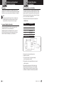
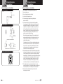
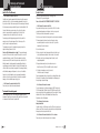
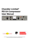
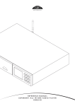
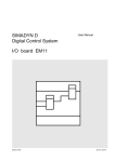
Introduction
Our Thanks to You and
FCC License Required
Our Thanks to You
•
Thank you for purchasing a Cobra amateur mobile radio. Properly used,
this Cobra product will give you many years of reliable service.
FCC License Required
Owner’s Manual
•
The United States Federal Communications Commission (FCC)
requires that users of the frequencies on which this radio
operates be licensed. See page 16 for licensing and other
FCC information.
The Cobra line of quality products includes:
CB Radios
microTALK® Radios
Radar/Laser Detectors
Safety Alert® Traffic Warning Systems
Handheld GPS Receivers
Mobile GPS Navigation Systems
HighGear® Accessories
CobraMarine™ VHF Radios
Power Inverters
AMATEUR 10 METER MOBILE RADIO
Accessories
200 GTL DX
Printed in Philippines
Part No. 480-217-P
Version A
© 2005 Cobra® Electronics Corporation
6500 West Cortland Street
Chicago, Illinois 60707 USA
www.cobra.com
A1 English
Nothing comes close to a Cobra®
English
Nothing comes close to a Cobra®
English
Controls and Indicators
Introduction
Introduction
Controls and Indicators
•
SWR /
S/RF
Dim /
SWR CAL
CW / FM / AM /
USB / LSB
Analog
Meter
Band
A/B/C/D
Microphone and Features
Microphone
Press-To-Talk
Button (PTT)
Dual 7
Segment
Frequency
Display
Six Digit
Frequency
Display
WARNING
RX / TX
Indicator
RISK OF ELECTRIC SHOCK.
DO NOT OPEN. DO NOT REMOVE
COVER OR BACK. NO USER
SERVICEABLE PARTS INSIDE.
REFER TO SERVICING TO
QUALIFIED SERVICE PERSONNEL.
Features
+10
KHz
NB / ANL
High/Low Power
R Beep
External
Speaker
Connector
Microphone
Connector
•
Antenna
Warning
Indicator
Microphone Gain
(center knob)
RF Gain
Off / On / Volume
(outer ring)
(center knob)
Squelch
(outer ring)
Clarifier
Continuous
Fine (center knob)
Wave Connector
Coarse (outer ring)
Frequency
Selector
Echo
(center knob)
SWR CAL
(outer ring)
Antenna
Connector
- -4341 Operating Frequencies
Allows operation on all
available frequencies.
- -4Antenna Warning Indicator
Illuminates when the antenna system
needs repair or adjustment.
- -4Dual Finals
Provides steady output power.
- -4Frequency Display
Large 6 digit numeric and
Dual 7 Segment displays on
the front of the unit.
- -430 Watts Output Power
Provides maximum
power on AM and FM
100 PEP SSB.
- -4Dual Power
Allows operation on Low and
High power.
- -4All Mode Operation
• Continuous wave
• Frequency or amplitude modulation
• Upper or lower sideband.
- -4SWR Calibration
Allows measurement and adjustment
of the antenna system.
- -4Echo Control
Allows control of echo effect.
- -4Large Analog Meter
Provides high visibility of
status meter.
- -4NightWatch™ Panel
Electroluminescent illumination of
front panel for night operation.
- -44 Pin Front Mic Connector
Allows convenient installation in-dash.
- -4Mic Gain Control
Allows increased voice clarity by
dynamically boosting microphone.
This Cobra radio has a superior receiver that includes an RF gain control and noise
blanker circuitry as well as an automatic noise limiter. The receiver also features
increased protection against cross modulation and strong adjacent signals.
Power Cord
Connector
A2 English
To obtain maximum performance, please read carefully the descriptions and
operating instructions in this manual.
A3 English
•
Contents
Introduction
Introduction
Our Thanks to You . . . . . . . . . . . . . . . . . . . . . . . . . . . . . . . . . . . . . . . . . . . A1
FCC License Required . . . . . . . . . . . . . . . . . . . . . . . . . . . . . . . . . . . . . . . . . A1
Controls and Indicators . . . . . . . . . . . . . . . . . . . . . . . . . . . . . . . . . . . . . . . . A2
Microphone . . . . . . . . . . . . . . . . . . . . . . . . . . . . . . . . . . . . . . . . . . . . . . . . . A3
Features . . . . . . . . . . . . . . . . . . . . . . . . . . . . . . . . . . . . . . . . . . . . . . . . . . . A3
Your Mobile Radio
Specifications . . . . . . . . . . . . . . . . . . . . . . . . . . . . . . . . . . . . . . . . . . . . . . . . 2
Included in this Package . . . . . . . . . . . . . . . . . . . . . . . . . . . . . . . . . . . . . . . . 4
Installation and Connection . . . . . . . . . . . . . . . . . . . . . . . . . . . . . . . . . . . . . . 5
Operation . . . . . . . . . . . . . . . . . . . . . . . . . . . . . . . . . . . . . . . . . . . . . . . . . . . . 8
Controls . . . . . . . . . . . . . . . . . . . . . . . . . . . . . . . . . . . . . . . . . . . . . . . . . . . . . 9
Frequency . . . . . . . . . . . . . . . . . . . . . . . . . . . . . . . . . . . . . . . . . . . . . . . . . . 12
Indicators . . . . . . . . . . . . . . . . . . . . . . . . . . . . . . . . . . . . . . . . . . . . . . . . . . 14
Microphone . . . . . . . . . . . . . . . . . . . . . . . . . . . . . . . . . . . . . . . . . . . . . . . . . 14
Operating to Receive . . . . . . . . . . . . . . . . . . . . . . . . . . . . . . . . . . . . . . . . . . 15
Operating to Transmit . . . . . . . . . . . . . . . . . . . . . . . . . . . . . . . . . . . . . . . . . 15
Maintenance . . . . . . . . . . . . . . . . . . . . . . . . . . . . . . . . . . . . . . . . . . . . . . . . 16
Government Regulatory Information . . . . . . . . . . . . . . . . . . . . . . . . . . . . . . 16
Alternate Microphones and Installation . . . . . . . . . . . . . . . . . . . . . . . . . . . . 17
ARRL Q Signals . . . . . . . . . . . . . . . . . . . . . . . . . . . . . . . . . . . . . . . . . . . . . . 20
Warranty
Warranty . . . . . . . . . . . . . . . . . . . . . . . . . . . . . . . . . . . . . . . . . . . . . . . . . . . 22
Trademark Acknowledgement . . . . . . . . . . . . . . . . . . . . . . . . . . . . . . . . . . . 22
Customer Assistance
Product Service . . . . . . . . . . . . . . . . . . . . . . . . . . . . . . . . . . . . . . . . . . . . . . 23
Accessories . . . . . . . . . . . . . . . . . . . . . . . . . . . . . . . . . . . . . . . . . . . . . . . . . 24
Order Form and Optional Accessories . . . . . . . . . . . . . . . . . . . . . . . . . . . . . 25
Nothing comes close to a Cobra®
1
Your Mobile Radio
Specifications
Specifications
•
General
Specifications
Specifications
•
Receiver
Frequency Range
28.0 to 29.7 MHz
Frequency Control
Phase Lock Loop (PLL) synthesizer
Frequency Stability
0.005%
Audio Frequency
Response
300 to 3,000 Hz
Operating
Temperature Range
-22°F to 122°F (-6°C to + 50°C)
Maximum Signal
to Noise Ratio
45 dB
Antenna Impedance
50 ohms
Antenna Connector
Standard SO 239 type
Microphone
Input Voltage
Current Drain
Size
65 dB
Plug-in dynamic with Press-To-Talk switch and coiled cord
AM/FM: 60 dB
SSB/CW: 70 dB
13.8 V DC nominal, 15.9 V max., 10.0 V min.
(positive or negative ground)
RF Gain Control (AGC)
40 dB – adjustable for optimum signal reception
Squelch
Adjustable – threshold less than 0.5 µV
Transmit: 8.0 A AM/FM
15A SSB@100W PEP
Receive (squelched): 0.5 A
Receive (maximum audio output): 1.2 A
Automatic Noise
Limiter (ANL)
Switchable
Noise Blanker (NB)
Switchable
Receive Indicators
Meter shows relative signal strength.
Receive LED glows green when receiving a signal.
23⁄8"(H) x 77⁄8"(W) x 103⁄4"(D)
[6cm (H) x 20cm (W) x 27.3cm (D)]
6.5 lbs.
Meter (3-in-1)
Illuminated – indicates relative output power,
received signal strength, and SWR.
Built-in Speaker
4 watts
Low – 4 watts AM/FM 12 watts SSB
High – 30 watts AM/FM 100 watts PEP SSB
Frequency Response
300 to 3,000 Hz
Frequency Tolerance
500 Hz
Transmit Distortion
2%
Spurious Harmonic
Emission
-65 dB
Output Indicators
Meter shows relative RF output power and SWR.
Transmit LED glows red when transmitter is in operation.
Antenna Warning LED
Glows red when SWR is greater than 3.0.
English
AM: 0.5 µV for 10 dB S/N
FM/SSB/CW: 0.25 µV for 12 dB S/N
Adjacent
Channel Rejection
Weight
Power Output
Sensitivity
Image Rejection
Transmitter
2
Your Mobile Radio
External Speaker
Power Output
4 watts into external speaker
External Speaker
(Not Supplied)
8 ohms
(Specifications subject to change without notice)
Nothing comes close to a Cobra®
3
Your Mobile Radio
Included in this Package
Included in this Package
Your Mobile Radio
•
You should find all of the following items in the package with your radio.
Installation and Connection
Installation and Connection
•
Refer to the illustration on page A2 for connection points on the back of the
unit while installing your radio.
- -4Location
Transceiver
Universal Mounting Bracket
Plan the location of the transceiver and microphone brackets before starting the installation.
Select a location that is convenient for operation and does not interfere with the driver or
passengers in the vehicle. In automobiles, the transceiver is usually mounted below the
dash panel, with the microphone bracket beside it.
- -4Mounting
Your mobile radio is supplied with a universal mounting bracket. When mounting the bracket
and radio to your car, make sure it is mechanically strong. Also provide a good electrical
connection to the chassis of the vehicle. Proceed as follows to mount the transceiver:
Operating Instructions
Microphone
Controls and Indicators
Introduction
Controls and Indicators
•
SWR /
S/RF
Dim /
SWR CAL
CW / FM / AM /
USB / LSB
Analog
Meter
+10
KHz
NB / ANL
High/Low Power
R Beep
External
Speaker
Connector
Band
A/B/C/D
Microphone
Connector
Off / On / Volume
(center knob)
Squelch
(outer ring)
Continuous
Wave Connector
Power Cord
Connector
A2 English
Microphone Bracket
Dual 7
Segment
Frequency
Display
Six Digit
Frequency
Display
RX / TX
Indicator
Antenna
Warning
Indicator
Microphone Gain
(center knob)
RF Gain
(outer ring)
Clarifier Fine
(center knob)
Coarse
(outer ring)
Frequency
Selector
Echo
(center knob)
SWR CAL
(outer ring)
- -4Mount the Transceiver
1. After you have determined the most convenient location in your vehicle, hold the mobile
radio with the mounting bracket in the exact location desired. If nothing will interfere
with mounting it in the desired position, remove the thumbscrews and use the
mounting bracket as a template to mark the holes for the mounting screws. Before
drilling the holes, make sure nothing behind the surface will be damaged or interfere
with the installation.
2. Connect the antenna cable plug to the standard receptacle (ANT) on the rear panel.
Most antennas are terminated with a type PL-259 plug and mate with the receptacle.
Antenna
Connector
3. Connect the red DC power input wire (with the fuse) to +13.8 V DC. This wire extends
from the rear panel. In automobile installation, connect directly to positive terminal
(red) of the vehicle's battery. We recommend that you install a fuse within six inches
of the battery.
4. Connect the black lead to -13.8 V DC to the negative (black) post of the battery.
5. Mount the microphone bracket on either side of the transceiver, using the two screws
supplied. When mounting in an automobile, place the bracket under the dash so the
microphone is readily accessible.
6. Attach the microphone cable to the connector on the face of the transceiver.
NOTE
If the radio is to be used to send Morse code, an optional telegraph
key will need to be connected to the CW Key Connector on the back
of the unit.
4
English
Nothing comes close to a Cobra®
5
Your Mobile Radio
Installation and Connection
Installation and Connection
- -4Ignition Noise Interference
Use of a mobile receiver at low signal levels is normally limited by the presence of
electrical noise. The primary source of noise in automobile installations is from the
generator and ignition system in the vehicle. Under most operating conditions, when
signal level is adequate, the background noise does not present a serious problem.
However, when extremely low-level signals are being received, the transceiver may
be operated with vehicle engine turned off. The unit requires very little current and
therefore will not significantly discharge the vehicle battery.
Your Mobile Radio
•
Even though your mobile radio has ANL and NB controls, in some installations ignition
interference may be high enough to make good communications impossible. The electrical
noise may come from several sources. Many possibilities exist and variations between
vehicles require different solutions to reduce the noise. Consult your Cobra dealer or a
two-way radio technician for help in locating and correcting the source of severe noise.
- -4Antenna
In addition to transmitter power, the antenna is an important factor affecting transmission
distance. Only a properly matched antenna system will allow maximum power transfer
from the 50 ohm transmission line to the radiating element. In mobile installations
(cars, trucks, etc.), an antenna system that is non-directional should be used.
A vertically polarized, quarter-wavelength whip antenna provides the most reliable
operation and greatest range. Shorter, loaded-type whip antennas are more attractive,
compact and adequate for applications where the maximum possible distance is not
required. Also, the loaded whips do not present the problems of height imposed by
a full quarter-wavelength whip.
Mobile whip antennas utilize the metal body of the vehicle as a ground plane.
When mounted at a corner of the vehicle, they are slightly directional, in the direction
of the body of the vehicle. For all practical purposes, however, the radiation pattern
is non-directional. The slight directional characteristic will be observed only at extreme
distances. A standard antenna connector (type SO 239) is provided on the transceiver
for easy connection to a standard PL 259 cable termination.
If the transceiver is not mounted on a metal surface, it is necessary to run a
separate ground wire from the unit to a good metal electrical ground in the vehicle.
6
English
Installation and Connection
Installation and Connection
- -4Tuning the Antenna for Optimum SWR
Because such a wide variety of base and mobile antennas are available, this section
will concern itself only with the usual types of mobile adjustable antennas.
•
Antenna length is directly related to signal frequency. Therefore, it must be
tuned to resonate optimally throughout the frequency range of the transceiver.
Lower frequencies require a longer antenna than higher frequencies.
Due to the various methods of adjusting antennas for proper SWR, we have
chosen what we think is the optimum method:
A. Antennas with adjustable screws (set screws).
1. Start with the antenna extended and tighten the setscrew lightly enough so
that the antenna can be lightly tapped with your finger for easy adjustment.
2. Set your mobile radio to your desired operating frequency or the center of
the range of frequencies you plan to use. Press the PTT (Press-To-Talk) switch,
and tap the antenna (making it shorter). The SWR meter will show a lower reading
each time the antenna is tapped. By continuing to shorten the antenna, you will
notice the SWR reading will reach a low point and then start rising again.
This means that you have passed the optimum point for the middle frequency.
3. Extend the antenna a short distance and again follow the procedure above.
4. When the lowest point has been reached, switch to 28.0 MHz and then
to 29.7 MHz and compare SWR readings. They should be almost equal.
B. Antennas that must be cut to proper length.
1. Follow the procedure as in A above, but adjust the length
by cutting in 1⁄8" increments until a good match is obtained.
2. Be very careful not to cut too much off the antenna at one time.
Once it is cut, it can no longer be lengthened.
3. The whip is easily cut by filing a notch all the way around,
then breaking the piece off with pliers.
NOTE
The proper setting is achieved when the SWR is 1.5 or below and when it has
the same reading for the low and high frequencies in the range you plan to use.
Nothing comes close to a Cobra®
7
Your Mobile Radio
Installation and Connection
and Operation
Installation and Connection
Your Mobile Radio
•
If you are having difficulties in adjusting your antenna, check the following:
1. All doors must be closed when adjusting the antenna.
2. Make sure the antenna base is grounded.
4. Try a different location on your car — keeping in mind the radiation pattern you want.
6. Try a different location in your neighborhood. Stay away from large metal objects
(metal utility or light poles, fences, etc.) when adjusting.
NOTE
The radio will operate into a SWR of 2 to 1 indefinitely and sustain an
SWR of 20 to 1 for a maximum of 5 minutes at rated operating conditions.
English
•
- -4RF Gain
Used to reduce the gain of the RF amplifier when receiving very strong signals.
- -4External Speaker
The external speaker jack (EXT) on the rear panel is used for remote receiver monitoring.
The external speaker should have 8 ohms impedance and be able to handle at least
four watts. When the external speaker is plugged in, the internal speaker is disabled.
8
- -4Off / On / Volume
Turn clockwise to apply power to the unit and to set the desired listening level.
During normal operation, the volume control is used to adjust the output level
obtained either at the transceiver speaker or the external speaker, if used.
This control is used to cut off or eliminate receiver background noise in the absence
of an incoming signal. For maximum receiver sensitivity, it is desired that the control be
adjusted only to the point where the receiver background noise or ambient background
noise is eliminated. Turn fully counterclockwise, then slowly clockwise, until the receiver
noise disappears. Any signal to be received must now be slightly stronger than the
average received noise. Further clockwise rotation will increase the threshold level
that a signal must overcome in order to be heard. Only strong signals will be heard
at the maximum clockwise setting.
5. Make sure the antenna is perfectly vertical.
There are 17 controls and 4 indicators on the front panel of your mobile radio.
These are shown in the illustration on page A2 which may be folded out for
reference when using this section.
Controls
- -4Squelch
3. Check your coaxial cable routing — it may be pinched where routed into the car.
Operation
Controls
- -4Microphone Gain
Adjusts the microphone gain in the transmit mode. This controls the gain to the extent
that full talk power is available several inches away from the microphone.
•
- -4CW / FM / AM / USB / LSB
Selects the mode of operation.
Nothing comes close to a Cobra®
9
Your Mobile Radio
Controls
Controls
- -4High Power
Places the transmitter in high power (30 watts) mode when the button is pressed to
the in position and in low power (4 watts) mode when the button is in the out position.
- -4SWR / S/RF
When this button is in the S/RF (out) position, the display meter swings proportionately
to the strength of the signal received or the output power being transmitted.
When the button is in the SWR (in) position, the standing wave ratio is measured
on the display meter.
Your Mobile Radio
•
Controls
Controls
- -4NB / ANL
When this button is in the ANL (in) position, only the automatic noise limiter in
the audio circuits is activated. When the button is in the NB/ANL (out) position,
the RF noise blanker also is activated. The RF noise blanker is very effective for
repetitive impulse noise such as ignition interference.
- -4Echo
This control is used to adjust the output level of the echo circuit. It is also
detented at the fully counter clockwise position to turn off the echo circuit.
- -4Dim / SWR CAL
Adjusts the NightWatch™ panel and meter brightness in steps from min. to max.
when this button is pressed and released repeatedly. The antenna warning LED is
not affected by this control.
- -4R Beep
When this button is pressed to the in position, the radio will insert a tone
(Roger beep) to indicate the end of each transmission as the Press-To-Talk
button on the microphone is released.
To place this control in the CAL position, press and hold the button. The SWR
function can then be calibrated on the display meter by adjusting the SWR CAL
control to move the needle to the calibration mark on the display meter face.
When the button is in the out position, the tone function will be off.
- -4SWR CAL
This control is used in conjunction with the DIM / SWR CAL button to calibrate the
standing wave ratio circuit to full scale on the display meter in preparation for measuring
the standing wave ratio that the antenna is presenting to the transceiver.
The standing wave ratio can be checked to insure that maximum power is being
radiated for the longest signal range. The antenna must be in good condition, properly
adjusted and matched to your transceiver. The SWR function of the display meter lets
you easily measure your antenna condition. To operate this function, select a frequency
near the middle of the range such as 28.850 MHz or the one you plan to use most.
With the power on, press and hold the DIM / SWR CAL button. Press and hold the
microphone Press-To-Talk button and, using the SWR CAL knob, adjust the meter
to the CAL position indicated on the display meter. Then, release the microphone
and DIM / SWR CAL buttons. Press the SWR / S/RF to the in position and again
press and hold the microphone Press-To-Talk button and read the SWR indicated.
Lower figures are the better, with 1 being ideal. Generally, readings up to 3 are
acceptable, but a reading greater than 3 indicates that you are losing radiated
power and antenna adjustment may be advisable. When finished, return the
SWR control to the minimum position.
10 English
•
- -4Clarifier
The clarifier function is used to make small adjustments in frequency
when using the radio in single sideband mode (USB or LSB). Thereby,
the receiver can be matched to the signal being received for the best
voice clarity at the speaker.
The outer ring makes coarser and the inner knob finer adjustments.
Both controls increase frequency when turned clockwise and decrease
it when turned counter-clockwise.
Nothing comes close to a Cobra®
11
Your Mobile Radio
Frequency
Your Mobile Radio
Frequency
•
Three controls and one indicator are used together to set and display the radio
frequency on which your mobile radio will receive and transmit signals. In this
connection, it is important to understand the frequency bands built into the unit
and the way they are displayed on the Dual 7 Segment Display.
The 10 meter frequency range is broken down into four bands on your
mobile radio. These are selected using the Band A / B / C / D knob.
Band
Frequency Range — MHz
A
28.000 – 28.495
B
28.500 – 28.995
C
29.000 – 29.495
D
29.500 – 29.700
Frequency
- -4Frequency Display
Receive and transmit frequencies are shown directly by the 6 digit numeric
display in 100 Hz increments.
Frequency Display
000000 00
6 Digit Numeric Display
Dual 7 Segment Display
•
Frequencies are also displayed on the Dual 7 Segment Display using a combination of
numerical figures and decimal points. The figures indicate the first two values after the
decimal point in the frequency, such as the 00 in 28.005 MHz. The right hand decimal point
in the display indicates whether the third value after the decimal point in the frequency is
0 or 5 — if the right hand decimal is visible on the display, the third value is 5; if it is not
visible, the third value is 0. The left hand decimal point in the display (between the two
figures) indicates whether the two values before the decimal point in the frequency are
28 or 29 — if the left hand decimal is visible on the display, the first two values are 29;
if it is not visible, the first two values are 28. Refer to the examples in the following table.
Frequency Display
Within each band, frequencies can be selected in 5 kHz or 10 kHz increments,
such as 28.005 MHz in Band A or 29.455 MHz in Band C. These are selected
using the Frequency Selector knob after the band has been chosen.
Frequency
Frequency
0 0
28.000
0 0.
28.005
0.0
29.000
0.0.
29.005
3 5
28.350
4 5.
28.455
2.5
29.250
6.3.
29.635
Channel Display
88
28/29 MHz
0/5 kHz
- -4Band A / B / C / D
This control selects the desired frequency band.
- -4Frequency Selector
This detented control is a 360º multi-position switch used to increase or
decrease the operating frequency in 5 or 10 kHz steps within the selected band.
- -4+10 kHz
When this button is in the out position, the operating frequency is increased or
decreased by 5 kHz with each click of the frequency selector knob. When the button
is in the in position, faster tuning is available because the operating frequency is
increased or decreased by 10 kHz with each click of the frequency selector knob.
12 English
Nothing comes close to a Cobra®
13
Your Mobile Radio
Indicators and Microphone
Indicators
- -4Analog Meter
The meter needle swings proportionally to the strength of the incoming signal
or RF output power in receive or transmit modes.
Your Mobile Radio
•
•
1. Be sure the power source, microphone and antenna are properly connected.
2. Turn the unit on by turning the volume knob clockwise and set the volume for a
comfortable listening level.
3. Set the CW / FM / AM / USB / LSB switch to the desired mode.
4. Set the RF gain control fully clockwise for maximum RF gain.
5. Listen to the background noise from the speaker, then turn the squelch ring slowly
clockwise until the noise just disappears (no signal should be present). Leave the
control at this setting. The squelch is now properly adjusted. The receiver will remain
quiet until a signal is actually received. Do not advance the control too far, or some
of the weaker signals will not be heard.
- -4RX / TX Indicator
This indicator glows green when in receive mode and red when in transmit mode.
- -4Antenna Indicator
This indicator glows red whenever the standing wave ratio is greater than 3 to 1.
6. Select the desired frequency with the band and frequency selector knobs.
7. Adjust other controls as desired.
•
The receive and transmit modes are controlled by the Press-To-Talk (PTT) switch
on the microphone. Press the switch to transmit, release it to receive. When transmitting,
hold the microphone two inches from the mouth and speak clearly in a normal voice.
To substitute for the supplied low-impedance (500 ohm) dynamic microphone,
see the alternate microphones and installation section on page 17.
Operating to Receive
To begin operating your radio:
When used to tune the antenna or monitor the quality of the coaxial cable and
RF electrical connections, the needle swings proportionally to the ratio of standing
wave voltage and RF output. If there is any degradation in these, due to humidity,
salt, spray, vibration or corrosion, the SWR meter reading will rise, thereby
indicating that a problem exists.
Microphone
Operating to Receive and
Transmit
Operating to Transmit
•
To transmit a signal:
1. Select the desired frequency for transmission if different from the one
chosen to receive.
2. Set the microphone gain knob fully clockwise.
3. If the frequency is clear, depress the Press-To-Talk switch on the
microphone and speak in a normal voice.
14 English
Nothing comes close to a Cobra®
15
Your Mobile Radio
Maintenance and Government
Regulatory Information
Maintenance
Your Mobile Radio
•
The transceiver is specifically designed for the environment encountered in mobile
installations. The use of all solid-state circuitry and its light weight result in high reliability.
Should a failure occur, however, replace parts only with identical parts. Do not substitute.
NOTE
If the performance described in the operation sections is not obtained, review
the installation instructions to insure that proper procedures were followed.
If a problem still exists, refer to the product service section on page 23.
Government Regulatory Information
This device complies with part 15 of the FCC Rules. Operation is subject to the
condition that this device does not cause harmful interference.
Transmitting using this radio requires an Amateur Radio License. If you live in the
United States, visit http://www.fcc.gov or http://www.arrl.org for further licensing
information. In Canada, visit http://strategis.ic.gc.ca or http://www.rac.ca/.
Alternate Microphones
and Installation
Alternate Microphones and Installation
•
For best results, the user should select a low-impedance dynamic type microphone
or a transistorized microphone. Transistorized-type microphones have a low output
impedance characteristic. The microphone must be provided with a four-lead cable.
The audio conductor and its shielded lead comprise two of the leads. The third lead
is for receive control, the fourth is for transmit control.
The microphone should provide the functions shown in the schematic below.
- -44 Wire Mic Cable
Pin Number
•
Mic Cable Lead
1
Grounding
2
Audio Lead
3
Transmit Control
4
Receive Control
Fig. 1 Cobra microphone schematic
If the microphone to be used is provided with pre-cut leads,
they must be revised as follows.
1. Cut leads so that they extend 7⁄16" beyond the plastic insulating
jacket of the microphone cable (see Fig. 2).
2. All leads should be cut to the same length. Strip the ends of each wire 1⁄8"
and tin the exposed wire.
Before beginning the actual wiring, read carefully the circuit and wiring
information provided with the microphone you select. Use the minimum
heat required in soldering the connections. Keep the exposed wire lengths
to a minimum to avoid shorting when the microphone plug is reassembled.
16 English
Nothing comes close to a Cobra®
17
Your Mobile Radio
Alternate Microphones
and Installation
Alternate Microphones and Installation
Your Mobile Radio
•
Alternate Microphones
and Installation
Alternate Microphones and Installation
•
To wire the microphone cable to the plug provided, proceed as follows:
Fig. 2 Microphone cable preparation
1. Remove the retaining screw.
2. Unscrew the housing from the pin receptacle body.
3. Loosen the two cable clamp retainer screws.
4. Feed the microphone cable through the housing, knurled ring and
washer as shown Fig. 3B.
5. The wires must now be soldered to the pins as indicated in the wiring table.
If a vise or clamping tool is available, it should be used to hold the pin receptacle
body during the soldering operation so that both hands are free to perform the
soldering. If a vise or clamping tool is not available, the pin receptacle body can
be held in a stationary position by inserting it into the microphone jack on the
front panel. The numbers of the pins of the microphone plug are shown in Fig 4,
as viewed from the back of the plug. Before soldering the wires to the pins,
pre-tin the wire receptacle of each pin of the plug.
Fig. 3 Microphone plug wiring
Be sure that the housing and the knurled ring of Fig. 3 are pushed back onto the
microphone cable before starting to solder. If the washer is not captive to the pin
receptacle body, make sure that it is placed on the threaded portion of the pin
receptacle body before soldering.
If the microphone jack is used to hold the pin receptacle during soldering operation,
best results are obtained when the connections to pins 1 and 3 are made first and
then the connections to pins 2 and 4. Use a minimum amount of solder and be
careful to prevent excessive solder accumulation on pins, which could cause a
short between the pin and the microphone plug housing.
Fig. 4 Microphone plug pin numbers viewed from rear of pin receptacle
3
2
4
1
6. When all soldering connections to the pins of the microphone are complete, push the
knurled ring and the housing forward and screw the housing onto the threaded portion
of the pin receptacle body. Note the location of the screw clearance hole in the plug
housing with respect to the threaded hole in the pin receptacle body. When the housing
is completely threaded into the pin receptacle body, a final fraction of a turn either
clockwise or counterclockwise may be required to align the screw hole with the
threaded hole in the pin receptacle body. When these are aligned, the retaining
screw is then screwed into place to secure the housing to the pin receptacle body.
7. The two cable clamp retainer screws should now be tightened to secure the
housing to the microphone cord. If the cutting directions have been carefully followed,
the cable clamp should secure to the insulation jacket of the microphone cable.
8. Upon completion of the microphone plug wiring, connect and secure the
microphone plug in the transceiver.
18 English
Nothing comes close to a Cobra®
19
Your Mobile Radio
ARRL Q Signals
ARRL Q Signals
Your Mobile Radio
•
ARRL Q Signals
ARRL Q Signals
The most commonly used are shown bold.
Some have slightly modified meanings in everyday usage.
QSD
Is my keying defective? Your keying is defective.
QSG
Shall I send ____ messages at a time? Send ____ messages at a time.
The official list follows.
QSK
Can you hear me between your signals and if so can I break in on your
transmission? I can hear you between my signals; break in on my transmission.
QSL
Can you acknowledge receipt? I am acknowledging receipt.
QSM
Shall I repeat the last message which I sent you, or some previous message?
Repeat the last message which you sent me (or message(s) number(s) ____).
QSN
Did you hear me (or ____) on ____ kHz? I did hear you (or ____) on ____ kHz.
QSO
Can you communicate with ____ direct or by relay?
I can communicate with ____ direct (or by relay through ____).
QRA
What is the name of your station? The name of your station is ____.
QRG
Will you tell me my exact frequency (or that of ____)? Your exact frequency
(or that of ____) is ____ kHz.
QRH
Does my frequency vary? Your frequency varies.
QRI
How is the tone of my transmission?
The tone of your transmission is ____ (1. Good, 2. Variable, 3. Bad).
QRJ
Are you receiving me badly? I cannot receive you. Your signals are too weak.
QRK
What is the intelligibility of my signals (or those of ____)?
The intelligibility of your signals (or those of ____) is ____
(1. Bad, 2. Poor, 3. Fair, 4. Good, 5. Excellent).
QSP
Will you relay to ____? I will relay to ____.
QST
General call preceding a message addressed to all amateurs
and ARRL members. This is in effect “CQ ARRL.”
QRL
Are you busy? I am busy (or I am busy with ____). Please do not interfere.
QSU
QRM
Is my transmission being interfered with? Your transmission is
being interfered with ____ (1. Nil, 2. Slightly, 3. Moderately,
4. Severely, 5. Extremely).
Shall I send or reply on this frequency (or on ____ kHz)?
Send or reply on this frequency (or ____ kHz).
QSV
Shall I send a series of Vs on this frequency (or on ____ kHz)?
Send a series of Vs on this frequency (or on ____ kHz).
QRN
Are you troubled by static? I am troubled by static ____ (1-5 as under QRM).
QSW
QRO
Shall I increase power? Increase power.
Will you send on this frequency (or on ____ kHz)?
I am going to send on this frequency (or on ____ kHz).
QRP
Shall I decrease power? Decrease power.
QSX
Will you listen to ____ on ____ kHz? I am listening to ____ on ____ kHz.
QRQ
Shall I send faster? Send faster (____ WPM).
QSY
QRS
Shall I send more slowly? Send more slowly (____ WPM).
Shall I change to transmission on another frequency?
Change to transmission on another frequency (or on ____ kHz).
QRT
Shall I stop sending? Stop sending.
QSZ
Shall I send each word or group more than once?
Send each word or group twice (or ____ times).
QRU
Have you anything for me? I have nothing for you.
QTA
Shall I cancel message number ____? Cancel message number ____.
QRV
Are you ready? I am ready.
QTB
QRW
Shall I inform ____ that you are calling on ____ kHz? Please inform ____
that I am calling on ____ kHz.
Do you agree with my counting of words? I do not agree with your
counting of words. I will repeat the first letter or digit of each word or group.
QTC
QRX
When will you call me again? I will call you again at ____ (on ____ kHz).
How many messages have you to send? I have ____
messages for you (or for ____).
QRY
What is my turn? Your turn is numbered ____.
QTH
What is your location? My location is ____.
QRZ
Who is calling me? You are being called by ____ (on ____ kHz).
QTR
What is the correct time? The correct time is ____.
QSA
What is the strength of my signals (or those of ____)?
The strength of your signals (or those of ____) is ____.
(1. Scarcely perceptible, 2. Weak, 3. Fairly Good, 4. Good, 5. Very Good).
QTV
Shall I stand guard for you? Stand guard for me.
QTX
Will you keep your station open for further communication with me?
Keep your station open for me.
QUA
Have you news of ____? I have news of ____.
QSB
20 English
Are my signals fading? Your signals are fading.
Nothing comes close to a Cobra®
21
Warranty
Warranty and Trademark
Acknowledgement
Limited Two-Year Warranty
- -4For Products Purchased in the U.S.A.
Cobra Electronics Corporation warrants that its Cobra radios, and the component
parts thereof, will be free of defects in workmanship and materials for a period of
two years from the date of first consumer purchase. This warranty may be enforced by
the first consumer purchaser, provided that the product is utilized within the U.S.A.
Customer Assistance
•
Product Service
Product Service
•
If you have any questions about operation or installing your new
Cobra product, or if you are missing parts…
Please call Cobra first! DO NOT RETURN THIS PRODUCT TO THE STORE!
- -4For Products Purchased in the U.S.A.
If your product should require service, please call at 800-638-3680 to obtain
a repair authorization number and the address to which to send your radio.
This will ensure the fastest turnaround time on your repair.
Cobra will, without charge, repair or replace, at its option, defective radios,
products or component parts, accompanied by proof of the date of first
consumer purchase, such as a duplicated copy of a sales receipt.
It will be necessary to furnish the following to have the product serviced and returned.
You must pay any initial shipping charges required to ship the product for
warranty service, but the return charges will be at Cobra’s expense, if the
product is repaired or replaced under warranty.
1. For warranty repair include some form of proof-of-purchase, such as
a mechanical reproduction or carbon of a sales receipt. If you send the
original receipt, it cannot be returned.
This warranty gives you specific legal rights, and you may also have other
rights which may vary from state to state.
2. Send the entire product.
Exclusions: This limited warranty does not apply: 1) To any product damaged
by accident; 2) In the event of misuse or abuse of the product or as a result of
unauthorized alterations or repairs; 3) If the serial number has been altered,
defaced or removed; 4) If the owner of the product resides outside the U.S.A.
3. Enclose a description of what is happening with the radio. Include a typed
or clearly printed name and address of where the radio is to be returned.
All implied warranties, including warranties of merchantability and fitness for
a particular purpose are limited in duration to the length of this warranty. Cobra
shall not be liable for any incidental, consequential or other damages; including,
without limitation, damages resulting from loss of use or cost of installation.
5. Ship prepaid and insured by way of a traceable carrier such as
United Parcel Service (UPS) or Priority Mail to avoid loss in transit.
4. Pack radio securely to prevent damage in transit. If possible, use the
original packing material.
6. If the radio is in warranty, upon receipt of your radio,
it will either be repaired or exchanged.
Some states do not allow limitations on how long an implied warranty lasts
and/or do not allow the exclusion or limitation of incidental or consequential
damages, so the above limitations may not apply to you.
Please allow approximately three to four weeks before contacting Cobra for status.
If the radio is out of warranty, a letter will automatically be sent informing you of
the repair charge or replacement charge.
- -4For Products Purchased Outside the U.S.A.
Please contact your local dealer for warranty information.
Trademark Acknowledgement
Cobra®, Nothing comes close to a Cobra® and the snake design are registered
trademarks of Cobra Electronics Corporation, USA. Cobra Electronics Corporation™
is a trademark of Cobra Electronics Corporation, USA.
•
- -4For Products Purchased in Canada
For out of warranty service, ship this product prepaid to: AVS Technologies Inc.,
2100 Trans Canada Hwy S., Montreal, Quebec, H9P 2N4. We reserve the right to
repair or replace the radio with an equivalent product. Please include the following
information: Date of Purchase, Model Number, Dealer Purchased From,
Dealer Address, Dealer Phone Number.
- -4For Products Used in Canada
Industry Canada Notice
Operation is subject to the following two conditions: 1) this device may not cause
interference, and 2) this device must accept any interference, including interference
that may cause undesired operation of this device.
- -4For Products Purchased Outside the U.S.A. or Canada
Please contact your local dealer for product service information.
22 English
Nothing comes close to a Cobra®
23
Customer Assistance
Accessories
Customer Assistance
Accessories
•
4 Pin Premium
Noise-Cancelling Microphone
Order Form and
Optional Accessories
Order Form
•
Name
4 Pin Premium
Noise-Cancelling Microphone
Address (No P.O. Boxes)
City
State/Province
Zip/Postal Code
Country
Telephone
Credit Card Number
HG M84
$74.95
HG M84W
Wood Grain
Type:
❒ Visa ❒ MasterCard ❒ Discover
Exp. Date
$74.95
Customer Signature
Dynamic
External Speaker
Noise Canceling
External Speaker
Amount
Noise Canceling With
Talk Back External Speaker
Shipping/Handling*
$10.00 or less. . . . . . . . . . $3.00
Item #
U.S. Cost Each
Qty
Amount
$10.01-$25.00 . . . . . . . . . $5.50
$25.01-$50.00 . . . . . . . . . $7.50
$50.01-$90.00 . . . . . . . . $10.50
$90.01-$130.00 . . . . . . . $13.50
$130.01-$200.00 . . . . . . $16.50
$200.01+. . . . . 10% of purchase
HG S100
$21.95
HG S300
$28.95
HG S500
$32.95
*For AK, HI and PR add
additional $26.95 for FedEx Next
Day or $10.95 for FedEx 2nd
Day. Excludes weekend and
holiday shipments.
Tax Table
Please allow two to three weeks
California. . 7.25%
for delivery in the U.S. Prices
Illinois . . . . 8.75%
subject to change without notice.
Indiana . . . 6%
U.S. Subtotal
Michigan . . 6%
Ohio . . . . . 6%
Wisconsin . 5%
(Tax if Applicable)
Shipping/Handling
Optional Accessories
The Cobra
line of quality
products includes:
Total
•
You can find quality Cobra products and accessories at your local
Cobra dealer, or in the U.S.A., you can order directly from Cobra.
CB Radios
microTALK® Radios
Radar/Laser Detectors
Safety Alert® Traffic
Warning Systems
Handheld GPS Receivers
Mobile GPS
Navigation Systems
HighGear® Accessories
CobraMarine™
VHF Radios
Power Inverters
Accessories
24 English
Ordering from U.S.A.
Call 773-889-3087 for pricing or visit www.cobra.com.
For credit card orders, complete and return this order
form to fax number 773-622-2269. Or call 773-889-3087
(Press 1 from the main menu) 8:00 a.m. to 6:00 p.m. CT,
Monday through Friday.
Make check or money order payable to:
Cobra Electronics, Attn: Accessories Dept.
6500 West Cortland Street, Chicago, IL 60707 USA
To order online, please visit our website: www.cobra.com.
Nothing comes close to a Cobra®
25
Introduction
Our Thanks to You and
FCC License Required
Our Thanks to You
•
Thank you for purchasing a Cobra amateur mobile radio. Properly used,
this Cobra product will give you many years of reliable service.
FCC License Required
Owner’s Manual
•
The United States Federal Communications Commission (FCC)
requires that users of the frequencies on which this radio
operates be licensed. See page 16 for licensing and other
FCC information.
The Cobra line of quality products includes:
CB Radios
microTALK® Radios
Radar/Laser Detectors
Safety Alert® Traffic Warning Systems
Handheld GPS Receivers
Mobile GPS Navigation Systems
HighGear® Accessories
CobraMarine™ VHF Radios
Power Inverters
AMATEUR 10 METER MOBILE RADIO
Accessories
200 GTL DX
Printed in Philippines
Part No. 480-217-P
Version A
© 2005 Cobra® Electronics Corporation
6500 West Cortland Street
Chicago, Illinois 60707 USA
www.cobra.com
A1 English
Nothing comes close to a Cobra®
English
Nothing comes close to a Cobra®
English