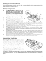
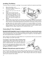
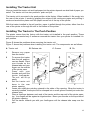
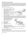
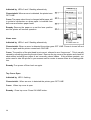
1
User’s Manual
Swift 90, Swift 120D and Swift 90x
Swift 240+ and Swift 240x
Swift 330+ and Swift 330x
1
Contents
Product Warranty ...................................................................................................................... 4
User Safety Instructions ........................................................................................................... 5
Introduction ................................................................................................................................ 6
About This Printer Manual .......................................................................................................... 6
What to do if you have problems .............................................................................................. 7
For the latest information ........................................................................................................... 7
http://www.citizen.co.uk ............................................................................................................... 7
Chapter 1 .................................................................................................................................... 8
Unpacking And Assembling Your Printer ................................................................................... 8
Unpacking The Printer ............................................................................................................... 8
Finding A Suitable Location ........................................................................................................ 8
Getting To Know Your Printer ...................................................................................................... 9
Printer Components ................................................................................................................... 9
Assembling The Printer ............................................................................................................. 9
Installing The Ribbon ............................................................................................................... 10
Connecting To Your Computer ................................................................................................. 10
Installing The Power Cable ...................................................................................................... 11
Chapter 2 .................................................................................................................................. 12
Paper Handling And Loading ................................................................................................... 12
Paper Types .............................................................................................................................. 12
Installing The Tractor Unit ........................................................................................................ 13
Installing The Tractor In The Push Position ............................................................................ 13
Installing The Tractor Unit In The Pull Position ....................................................................... 14
Setting The Paper Thickness ................................................................................................... 14
Adjusting The Paper Thickness Lever ..................................................................................... 15
Setting the Paper Select Lever ................................................................................................. 15
Paper Handling Summary Chart .............................................................................................. 15
Printing On Continuous Paper ................................................................................................. 16
Printing On Single Sheets ........................................................................................................ 16
Printing On Multi-Part Forms .................................................................................................... 17
Printing On Continuous Feed Labels ...................................................................................... 18
Printing On Envelopes ............................................................................................................. 18
Printing On Overhead Transparencies .................................................................................... 19
Special Paper Handling Features ............................................................................................ 19
Paper Parking ........................................................................................................................... 19
Paper Tear Off ........................................................................................................................... 20
Top Of Form Fine Adjustment - VTOP ...................................................................................... 21
Chapter 3 .................................................................................................................................. 22
The Control Panel .................................................................................................................... 22
Basic Operations ...................................................................................................................... 22
Changing The Appearance Of Text (The Mode Menu Groups) ............................................... 23
Changing The Font ................................................................................................................... 24
Changing The Text Pitch .......................................................................................................... 24
Changing The Style Of Printing ................................................................................................ 24
Power-On Settings ................................................................................................................... 25
Making A Print Out Of The Printer’s Default Settings ................................................................ 25
2
Changing The Default Settings ................................................................................................ 26
Menu Mode ............................................................................................................................... 27
Menu Functions ........................................................................................................................ 27
The Install Menu Group ............................................................................................................ 28
Tear-Off Postition Adjustments ................................................................................................. 29
Printer Self-Tests ...................................................................................................................... 29
Factory Default Settings ........................................................................................................... 30
The Buffer Memory ................................................................................................................... 30
Chapter 4 .................................................................................................................................. 31
Setting Up Your Printer To Work With Your Software ................................................................ 31
Microsoft® Windows® .................................................................................................................................................................................................. 31
IBM PCs Or Compatibles ......................................................................................................... 31
Choosing A Suitable Emulation ............................................................................................... 31
Codepages - International Characters .................................................................................... 32
Euro Currency Symbol ............................................................................................................. 32
Chapter 5 .................................................................................................................................. 33
Maintenance And Fault Finding ................................................................................................ 33
Problems And Solutions .......................................................................................................... 34
Error Messages And Their Causes ......................................................................................... 35
Chapter 6 .................................................................................................................................. 37
Printer Accessories .................................................................................................................. 37
RAM Modules ............................................................................................................................ 37
Automatic Sheet Feeder ........................................................................................................... 37
Installing The Automatic Sheet Feeder .................................................................................... 38
ASF Specification ...................................................................................................................... 39
Changing Between Continuous Forms And Single Sheets .................................................... 39
The Colour Kit ........................................................................................................................... 39
Using The Colour Kit ................................................................................................................ 40
The Printer Stand ...................................................................................................................... 40
The Serial interface .................................................................................................................. 40
Chapter 7 .................................................................................................................................. 43
Specifications for each printer .................................................................................................. 43
General Specifications ............................................................................................................. 44
3
Product Warranty
This product is covered by Citizen’s 2 year warranty for manufacturing defects. Please note that
items regarded as consumables, for example ribbons, where faults develop due to normal operational wear are not included. To obtain service under this warranty please return the product
in its original packaging to your supplier along with your purchase receipt.
The Citizen 2 year warranty is additional to your normal consumers rights.
Trademark Acknowledgements
Citizen:
Citizen Watch Co. Ltd. Japan, Citizen Systems Europe GmbH
Epson EX, FX, LQ:
Seiko Epson Corporation
IBM Personal Computer, IBM PC, IBM Proprinter:
International Business Machines Corporation
Microsoft, Windows:
Microsoft Corporation
NEC:
Nippon Electric Company
All rights reserved. No part of this publication may be reproduced, stored in a retrieval system or
transmitted in any form or by any mean, mechanical, photocopying, recording or otherwise,
without the prior written permission of Citizen Systems Europe. No liability is assumed with
respect to the use of the information contained herein. While every precaution has been taken in
the preparation of this manual, Citizen Systems Europe assumes no responsibility for errors or
omissions. Neither is any liability assumed for any damages resulting from the use of the
information contained herein.
Copyright 1999 © Citizen Systems Europe
http://www.citizen-europe.com
4
User Safety Instructions
1
2
3
4
5
•
•
•
•
6
7
8
9
10
11
12
•
•
•
•
Read all the enclosed unpacking and operating instructions and keep them for future
reference.
Follow all warnings and instructions marked on the product.
Do not use liquid or aerosol cleaners. Use a damp cloth with a small amount of detergent
to remove marks from the covers. For more persistent marks refer to your dealer for a
suitable cleaner.
Do not use this product near water. Switch the product off immediately if liquid is spilt
into it or if it has been exposed to rain or water.
The slots and openings on the product are provided for ventilation. To ensure reliable
operation of the product and to protect it from overheating, observe the following:
Do not block or cover the ventilation openings
Do not operate the product on a surface such as a bed, sofa or blanket as this may block
the openings and lead to overheating
Do not operate the product on or near a radiator or similar heat source
Do not enclose the product within an enclosure such as an acoustic hood without providing proper ventilation
Never push objects of any sort through the openings in the cover as they may touch
dangerous voltage points or short out parts which may result in a fire risk or an electric
shock.
Ensure that the local power supply is 220-240V at 50 Hz standards. If you are in any
doubt contact your dealer or a registered electrician.
Ensure that the power cable supplied with your printer matches the power cables of your
other computer equipment. If it does not, please contact your dealer or a registered
electrician.
Do not allow anything to rest on the power cable and do not position the product where
the power cable may be walked on.
Except as explained elsewhere in this manual, do not attempt to service the product
yourself. Opening or removing the covers may expose you to dangerous voltage points
or other risks and may invalidate your warranty. Refer all servicing to registered service
personnel. .
The mains plug on this equipment must always be used to disconnect the mains power
for servicing or repair. Please ensure that the socket outlet is installed near the equipment and is easily accessible.
Unplug this product from the power supply and refer servicing to registered personnel if:
The power cable or plug is damaged or frayed
The product has been exposed to rain or water or if liquid has been spilt into it
The product has been dropped or the cabinet damaged
The product exhibits a distinct change in performance, indicating a need for service
Warning: Attempts to service the printer yourself can be extremely dangerous and may also
further damage and invalidate the warranty.
Det matande vägguttaget skall placerat nära apparaten och vara lattátkomligt.
Stikkontakten skal placeres per apparatet og vare lettilgzngeligt.
5
Introduction
Thank you for purchasing this Citizen printer - you have made the right decision.
Citizen ranks amongst the top European printer manufacturers, producing innovative, high quality
printers backed by a worldwide organisation renowned for its reliable, precision engineered
products.
This manual covers a range of printer products, from 9-pin narrow carriage printers to 24-pin
wide carriage, high performance printing.
However, all machines in the range used the same set of features to operate the printer allowing
you to confidently operate any of our products. The printers are designed to be easy to setup,
operate and use and yet full of features and functions for those customers who need more
control.
About This Printer Manual
Chapter 1 tells you how to unpack and assemble your printer.
Chapter 2 describes the various paper handling facilities of the printer.
Chapter 3 describes the control panel and its functions.
Chapter 4 deals with the actual printing process and activating the printer from your computer
using popular commercial software packages.
Chapter 5 covers routine maintenance procedures and fault-finding, helping you to solve
common printer problems.
Chapter 6 gives you information on options and accessories for your printer
Chapter 7 details the full technical specifications of your printer.
We think you’ll find the manual and the printer functional and easy to use, but we will always be
glad to hear your comments so that we can improve our product where necessary.
6
What to do if you have problems
If you have any problems with your printer or require assistance in setting it up with your software we advise you to do the following:•
Read Chapter 4 and 5 of this user manual
•
Read the software driver documentation (if applicable)
•
Contact your local dealer from whom you purchased the printer.
•
Please visit our web site and take a look at the technical support pages. Details of this
are shown below
•
If you live in the United Kingdom, you can call our Printer Helpdesk on 0891 515 797.
Calls are charged at 50p per minute (correct at time of printing)
For the latest information
http://www.citizen-europe.com
Our web site contains the latest information on all our products. This will include updates
printer drivers, details of codepages currently supported by our printers and a comprehensive
FAQ (frequently asked questions) list.
In addition, there is a full distributor directory giving you details of a supplier nearest to you
and also details of suitable e-mail addresses or web sites that can provide and answer to your
enquiry.
7
Chapter 1
Unpacking And Assembling Your Printer
In this chapter, we’ll help you to set up your new printer. We’ll show you how to unpack your
printer and its components, as well as suggesting a suitable work location for it. We’ll also show
you how to install the ribbon and the power cable and how to connect the printer to your computer.
Unpacking The Printer
Lay the box on its side and slide the printer out by grasping the side packaging. As you unpack
your printer, set aside and save the packing materials. They have been specially designed to the
printer and will come in handy in case you ever need to transport it to a different location.
Are All Items Present? Having unpacked the printer and its component parts, check to see that
all the following items are there:
A
B
C
D
E
F
G
Printer
Single sheet guide
Power cable
Ribbon cartridge
Tractor feed unit
User manual
Paper feed knob (packaged
separately in box)
Are all Items Undamaged? Examine the printer and all the parts for obvious damage. If there
are any, contact your dealer or delivery agent immediately.
Installing The Paper Feed Knob To install the paper feed knob simply insert the cylinder end of
the knob with the four prongs into the paper knob opening on the right hand side of the printer.
Push the knob in gently until it engages. Then turn it to ensure the platen moves.
Finding A Suitable Location
Before you set up your printer you should think about the best location for it. But there are a few
considerations that can make life with your printer a lot easier:
•
•
•
•
•
8
Avoid areas subject to excessive heat (direct sunlight for example), humidity, dust or
grease
Provide a steady source of 220 to 240 volt electricity at 50 Hz
Choose a flat sturdy surface with enough room for the paper to flow freely into and out of
the printer
Position the printer so that connecting the power and computer cables will not interfere
with the paper flow
Do not put any objects on top of the printer, especially while printing as the extra weight
may cause the print head to jam
Getting To Know Your Printer
With the preliminaries out of the way let’s take a closer look at the printer components and the
paper controls to see what they do.
Printer Components
A
B
C
D
E
F
G
The power switch is used to turn the
printer on and off. It is at the left hand
side of the printer near the back. While
the printer is on, the top of the case may
feel warm to the touch. This is normal for
a high-speed printer and is nothing to
worry about.
The platen is the hard rubber roller that
carries the paper to the print head.
The paper feed knob is attached to the
platen. You can feed the paper and set its
position manually by turning this knob but only when no power is applied to the printer.
When the printer is on and off line you can feed the paper automatically by pressing the
line feed/form feed (LF/FF) or PARK/LOAD key - see Chapter 3.
The paper select lever is used to set the type of paper feed required, whether feed for
single sheets or tractor feed for continuous paper.
The paper thickness lever adjusts the print head to accommodate different paper
thicknesses and types of forms. It is located inside the printer, at the left hand side,
adjacent to the platen.
The tractor is the sprocket assemblies that feed continuous paper into the printer and
keep the paper properly aligned. Continuous paper, also called fan-fold, tractor feed or
pin-feed paper, is what you probably think of as computer paper. It consists of
continuous perforated sheets with holes punched along the sides.
The printer can accept optional modules to add more memory and a serial interface. It Is
located at the rear right hand side of the printer under the removable cover.
Assembling The Printer
Removing The Top Cover The top cover has two
basic positions. It is closed during printer operation
and open when you need to access the inside of
the printer. In order to install and change ribbons,
and make other adjustments to the printer, you’ll
need to open the hinged graduated plastic part, or
if it’s more convenient, remove the entire top cover.
This is ideally a two handed operation. After opening the graduated part gently lift the complete cover
away from the printer:
To replace it, insert the two bottom tabs on the cover into the slots on the printer case and lower
until it clips into position. You may need to push the cover down to ensure that it is correctly in
place.
9
Installing The Ribbon
The printer ribbon is enclosed in a cartridge. It is very easy to install and is carried out as follows:
1
2
3
4
5
6
7
Ensure the printer is off.
Remove the ribbon cartridge from
its packing materials.
Remove the top cover from the
printer.
Centre the print head by hand.
Holding the cartridge with the ribbon knob facing upwards, turn the
knob in the direction shown by the
arrow until the slack is taken up.
Make sure that the ribbon isn’t
twisted.
With the ribbon facing the back of the printer, place it in position between the print head
and the chrome ribbon guide (and on the ribbon cartridge itself). Ensure that the ribbon
knob is directly over the spindle projecting from the bottom of the printer. Gently push the
cartridge down until it clips into place. In practice it’s not quite as difficult as it sounds!
Move the print head side to side a few times to ensure that the ribbon drops into the
guiding grooves in front of the chrome ribbon guide and that it moves smoothly without
snagging. With the ribbon installed you can reinstall the top cover.
Connecting To Your Computer
Serial Or Parallel Connection? Your printer can be connected to your computer by either using
the parallel or an optional serial interface. The difference is that with a serial connection data is
sent to the printer one bit at a time, whereas a parallel connection allows several blocks of data
to be sent simultaneously. The choice depends on the type of computer you own and whether it
has other peripheral devices connected to it.
Most computers are designed for parallel transfer, as it is quicker than serial, but you can check
with your dealer if you wish to be certain.
Connecting To Your Printer Using A Parallel Cable
Connecting the cable to the printer is very simple. The
parallel interface connector is on the right side of the
printer, towards the back. The connector is tapered so
that you can only connect the cable one way; in other
words, it is impossible to connect up
it wrongly and risk
damaging your printer or computer.
Warning: Before making any connections make sure
that both the computer and the printer are turned off.
Move the small wire clamps out of the way and fit the cable connector to the connector on the
printer. The two should fit together with just a slight push. With the cable connected, press the
wire clamps into the notches on the cable socket. When fitting the other end to your computer
refer to your computer user manual.
10
Installing The Power Cable
The power cable fits into the socket located at the back of the printer on the right (viewed from the
back).
This socket has three prongs so that cable
will fit only one way. Make sure that power
switch is off before installing the power cable. Push the cable firmly into the socket
to make the connection secure.
The other end should be connected to a
standard mains power outlet socket.
11
Chapter 2
Paper Handling And Loading
Your printer offers great versatility in the kinds of paper you can use and the ways loading and
unloading them. This chapter discusses the details of these features in the following sections:
•
•
•
•
•
•
•
•
Paper types
Installing the tractor unit
Setting the paper thickness lever
Setting the paper select lever
Paper loading summary chart
Printing on continuous paper, single sheets, multi-part forms, labels, envelopes and
overhead transparencies
Quarter page printing
Special features - paper parking, paper tear-off and top of form fine adjustment
Paper Types
Your printer can handle many types of paper, including continuous paper, single sheets, multipart forms, labels and envelopes.
Continuous Paper Perforated paper is available in several widths. Your printer can handle any
continuous paper that is between 3¼ inches and 9¼ inches wide (this width does not include
the sprocket margin).
Single Sheets These can also vary in width and length. The paper guide can accommodate
paper as narrow as 7.2 inches and as wide as 10.1 inches.
Thick Paper Paper up to .007 inches thick feeds smoothly through this printer. This allows you
to use bond or ledger up to 100 gsm. However, for thicker papers you must adjust the printhead
away from the platen. See Setting the Paper Thickness Lever in this chapter for details.
Multi-Part Forms The printer can print on three-part forms (one original and two copies) with
the tractor mechanism in either the pull or push position. Four part forms require that the CPY
MODE menu is set ON. Multi-part forms, which have all layers of approximately the same
weight paper, give you the best printing results. Thinner paper layers provide better readability.
Labels Use only continuous labels. Always feed them through the bottom of the printer (with
the tractor in the pull position) for optimum printing results. Cut sheet labels and rear-feed
continuous labels make almost a full circle around the platen, causing labels to pop off occasionally. Also, you should never reverse feed labels through the printer.
Overhead Transparencies Prepare colour presentations on overhead transparencies using
the optional colour kit. Best results are obtained with darker colours (red, black, blue violet).
Only use the recommended dot matrix transparencies.
12
Installing The Tractor Unit
How you install the tractor unit and load paper into the printer depends on what kind of paper you
select. The tractor unit has two positions: push and pull.
The tractor unit is mounted in the push position at the factory. When installed, it fits snugly into
the rear of the printer. It works by gripping the edges of the continuous paper and pushing it
under and around the platen until the paper comes out of the top of the printer.
With the tractor installed in the pull position, paper is pulled through the printer, either from the
rear of the printer or through the slot in the bottom of the printer.
Installing The Tractor In The Push Position
The printer comes from the factory with the tractor unit installed in the push position. These
instructions are needed only if someone removed the tractor from your printer or installed it in
pull position.
Figure E shows the positions when removing the tractor unit
Figure F shows the positions when installing the tractor unit. The components are as follows:
A Tractor unit
1
2
3
4
5
6
7
B Release tab
C Groove
D Pin
Remove any paper
from the tractor.
To remove the tractor
from the pull position,
use two hands. Place
your thumbs on the
release tabs and your
fingers on the outside
of the printer case.
Press with your
thumbs and push the
tractor backwards.
The unit will lift up
easily.
Set the tractor unit
down in the rear
printer opening.
Locate two small pins pointing outward to the sides of the opening. When the tractor is
correctly installed, these pins will be clamped into a small groove located just under the
release tabs.
Place a forefinger between each end of the tractor and the rear wall of the printer opening. Your fingers will be against a ridged surface. Brace your thumbs on the top sides of
the printer opening.
Pull the tractor towards you with your forefingers until the release tabs snap over the
pins.
13
Installing The Tractor Unit In The Pull Position
Follow these instructions to install the tractor unit in the pull position:
A
B
C
D
E
F
Forward Notch
Front Pins
Half circle notch
Platform
Rear Pins
Spring Arm
1
2
Remove the top cover.
Remove any paper currently
loaded in the printer.
Place your thumbs on the release tabs located on both ends of the tractor unit. Grip the outside of the printer with
your fingers, push thumbs down and back. The tractor unit will pop backwards when it
releases from the push position.
Lift the tractor out with the metal crossbars.
Look at the tractor unit and locate the rear set of pins (E) on the right and left of the unit
and the notches (A) that hold the unit in position. On the printer itself, locate the front
pins (B) and the half-circle notch (C).
Using two hands, hold both ends of the tractor unit and position the tractor above the
central portion of the printer. The tractor feeders that grip the paper will be facing you and
the round crossbar will be above the square crossbar.
Rest the bottom of the spring arms (B) pin into the half circle notch (C). Keep the tractor
seated while you press downward from the tractor unit. The notches extending downwards from the tractor unit (A) will engage the two forward pins (B). When correctly
installed, the tractor unit clicks into place and feels very solidly attached. The tractor
feeders will be almost vertical.
Make sure the large paper select lever on the right-hand side of the printer is in the
forward (continuous forms) position.
3
4
5
6
7
8
Setting The Paper Thickness
Paper up to 0.007 inches thick will feed smoothly
through this printer. This allows you to use bond or
ledger up to 100 gsm. However, for thicker papers
you will need to adjust the printhead away from the
platen. For all other papers, keep the lever set to the
standard position. Remembering to make this small
adjustment gives you the best printing results.
Regardless of paper thickness, do not use a setting
closer to the platen than the standard position pointer
otherwise smudged output or and damage to the
printhead could result. See the table for the recommended paper thickness settings for the number of
copies you are using.
14
Adjusting The Paper Thickness Lever
You can find the paper thickness lever (A) by removing the top cover and looking inside the
printer opening at the far left end. The lever is mounted on a notched brace. Move the lever
toward the front of the printer for thicker papers. A small bump on the brace identifies the
standard location that is appropriate for most papers. Use the following tables to find the recommended setting for the type of paper you are using. You will see the numbers (-2 to +6) referred
to in the tables and on the brace of the paper thickness lever; they will help you locate the
correct lever position.
Paper Thickness Lever Position
Number Of Copies (Including Original)
-2
-1
0
+1
+2
+3
+4
+5
+6
Not used
Not used
1 or 2
3
4 or envelope
Envelope
Envelope
Envelope
Envelope
You’ll find that thicker paper feeds best when you use the bottom feeding feature of the printer.
Setting the Paper Select Lever
The paper select lever adjusts the printer for either continuous or single sheet paper If you look
closely at the lever, you’ll see what looks like a paper stack and single sheet next to the lever.
The lever is moved forward (to the paper stack) for continuous paper and back (to the single
sheet) for single sheets.
Paper Handling Summary Chart
The following table provides recommendations for the type of paper you are using, including
tractor unit position, paper feeding method, paper guide position, paper select lever and paper
thickness settings.
Paper Type
Tractor
Position
Paper Feed
Method
Paper Select
Lever
Paper Thickness
Lever
Continuos
Single Sheet
Multi-Copy
Labels
Envelopes
Push
Push
Pull
Pull
Push
Rear
Top
Bottom
Bottom
Top
Front
Back
Front
Front
Back
0
0
+1 or +2
+1
+2 - +6
*To print on 4-part paper, feed the paper from the bottom of the printer and set the CPY MODE
menu to ON.
When you install paper that is narrower than the capacity of the printer, place the paper near
side of the printer. The paper-out sensor is about two inches from the left edge of the printer and
the paper needs to cover it for successful operation.
15
Printing On Continuous Paper
Standard continuous feed paper can be fed from either the bottom or the rear. With rear feeding
you can take advantage of the printer’s special features of paper tear off, top of form fine adjustment and paper parking. You can stack the paper on the desk or table behind the printer (be sure
to allow space for the exiting paper so that it does not interfere with the incoming paper). With
bottom feeding you have convenient paper storage and less curling around the platen. We
recommend the push position.
Follow these steps to load continuous paper:
1
2
3
4
5
6
Be sure the tractor is mounted in the push
position. If it is not, use the instructions earlier in this Chapter to install it.
Move the paper select lever to the forward
(paper stack) position.
Unlock the levers on the tractor feeders and
adjust them to the approximate paper width.
See figure right.
Open the tractor feeder covers and place the
paper on the sprocket pins. Close the covers to clamp the paper.
Adjust the paper feeders until the paper is just taut between them, then relock the levers.
Install the paper guide/sheet separator in the sheet separator position. Do this by sliding
the small pins that point into the printer onto the L shaped channel openings on the
Outside of the printer guide extensions. Recline the paper guide backward. At the same
time slide the paper guide forward
slightly. Correctly installed, the paper guide lies flat on top of the
printer case above the paper.
A
B
C
D
E
Paper guide extension
Top cover (open)
Paper select lever
Paper guide/sheet separator
Paper holders
7
Move the paper holders (E) from
the sides into the middle of the
paper guide. This prevents your printed output from becoming accidentally jammed in
the paper guide on its way out of the printer.
Turn the printer on.
Press the PARK/LOAD key. This advances the paper to the starting print position.
8
9
Printing On Single Sheets
Single sheet feeding allows you to print on your company letterhead as well as many other types
of paper that are not available as continuous paper. It is a very easy procedure with the printer.
Follow these steps:
16
1
Be sure the tractor is in the
push position (if not, follow
the installation instructions
earlier in this chapter).
A
B
C
D
Paper guide extension
Paper holders
Paper guide
Paper select lever
2
Install the paper guide in the
upright position used for inserting paper. To do this,
hold the paper guide so that
the two corner extensions point downward into the printer. Slide the guide pins (A) onto
the L shaped channel slot. At the same time, position the paper guide forward slightly
allowing the pins to slip into the vertical channel. When installed correctly the paper
guide sits in an upright position.
Change the paper select lever (D) to the rear (single sheet) position. To use the paper
guide, simply move the left paper holder to the left as tar as it will go. This is the normal
position, however you can adjust it according to the size of paper you will be using. Insert
a sheet of paper and adjust the right paper holder to the paper width.
With the sheet of paper out of the printer, turn the printer on. The POWER light glows
and then flashes to indicate PAPER OUT.
a piece of paper head-in, face down, between the paper holders (as you would load
paper in a typewriter). Push the paper down gently to be sure it is all the way in.
Wait a brief time. The paper automatically feeds into the printer and stops when it reaches
the correct position for the starting line of print. The PAPER OUT light stops flashing.
Prepare to print by pressing the ON LINE key which illuminates the ON LINE light.
3
4
5
6
7
Your printer is now ready to receive data from your computer and print a document on single
sheets. The printer waits between pages for you to insert each new sheet and the control panel
reminds you to load paper by the POWER/PAPER OUT LED flashing.
Loading sheets repeatedly is faster and more efficient with the automatic sheet feeder. Read
more about them in Appendix C, Accessories.
Printing On Multi-Part Forms
Printing on multi-part forms uses the bottom feeding
method with the tractor in the pull position in order to
grip the exiting forms and pull them out. Feeding paper
in this way allows the forms almost straight through the
printer with minimal curling around the platen. However,
you will not be able to use the paper tear off, top of form
fine adjustment and paper parking features.
A
B
C
Recommended printer stand
Supply of forms feeds from below the printer
Tractor in the pull position
17
The printer is mounted on a printer stand allowing your supply of forms to sit below the printer
Follow these steps to load multi-part forms.
1
2
3
4
5
Be sure the tractor is in the pull position, if not, install it by following the instructions
earlier in this Chapter.
Turn the printer off before loading the forms from the bottom.
Remove the top cover.
Set the printer on its rear side.
Insert the forms through the slot in the bottom of the printer,
see below. Pull the forms through so that 4 or 5 inches
extend out of the printer. Make sure the paper covers the
paper out sensor.
A
B
C
Printer position for loading paper
Bottom feed continuous paper
Recommended printer stand
6
7
Set the printer right side up again.
Open the tractor feeder covers, position the forms on the
sprockets and close the covers. Be sure the paper is
straight. Adjust the distance between the tractor feeders, it
necessary by unlocking the lock levers and sliding the feeders until the paper is taut.
Relock the levers.
Move the paper select lever to the forward (paper stack) position.
Turn the paper feed knob clockwise until the second sheet of the forms s at the correct
starting print position. When printing with the tractor in the pull position, the first sheet of
the forms is unusable.
Set the paper thickness lever to +1 for 3-part forms, +2 for 4-part forms.
Replace the top cover, pressing on the push locations. The transparent part of the cover
rests against the tractor unit.
Turn the printer on.
If you are using 4-part forms, use the Setup mode to change CPY MODE to ON (see
Chapter 3.
8
9
10
11
12
13
Printing On Continuous Feed Labels
Printing on continuous feed labels uses the bottom feeding method with the tractor in the pull
position in order to grip the exiting labels and pull them out. Feeding media in this way allows
the labels to feed almost straight through the printer with minimal curling around the However,
you will not be able to use the paper tear off, top of form fine adjustment and paper parking
features. The printer should be mounted on a printer stand allowing your supply of labels to sit
below the printer.
Printing On Envelopes
Single sheet feeding allows you to print on No. 10, 6¾, 7¾ and DL size envelopes with a paper
weight of 45 to 75 gsm. For further details about paper types and specialist media, please
contact your supplier.
18
Printing On Overhead Transparencies
In addition to printing on paper, your printer can also print on overhead transparencies. You
should use transparencies specifically designed for dot matrix printers which have a slightly
rough surface rather than a smooth surface. Set the paper thickness lever to +1 and refer to the
section on “Printing on Single Sheets” earlier in this chapter.
Special Paper Handling Features
Your printer features a number of convenient functions for everyday paper handling
•
•
•
Paper parking
Paper tear-off - “zero” tear-off
Top of form fine adjustment - “VTOP” functions
First some background philosophy about the printer’s paper feeding method which should help
you to understand these special features.
The printer is designed with unique and sophisticated, yet easy-to-use paper movement features when continuous paper is used in the push tractor position. The printer has three paper
positions:
•
•
•
Parked
Top of form
Tear off
They operate sequentially using the PARK/LOAD key. With the printer off-line, the sequence is:
•
•
•
With paper in the parked position, pressing the PARK/LOAD key feeds the paper to the
top of form position
With paper in the top of form position pressing the PARK/LOAD key feeds the paper to
the tear off position
With paper in the tear off position pressing the PARK/LOAD key retracts the paper to the
park position
The sequence starts again if you press the PARK/LOAD key again.
Paper Parking
Paper Parking is a convenient feature that allows you to switch quickly between continuous feed
paper and single sheets. To use it, continuous paper must be fed in through the rear of the
printer with the tractor in the push position.
It works by backing the continuous paper out of the printer to where it is no longer touching the
platen. However, the paper remains in the tractor feeder, ready to feed into the printer.
To park your continuous paper and switch to single sheet mode:
1
2
With the print idle, tear off the continuous paper after the last page. Press the ON LINE
key to take the printer off line.
Press the PARK/LOAD key. The paper will feed backwards out of the printer. If the printer
is not at the top-of-form position, the paper will feed upwards first. In this case, press the
19
3
4
PARK/LOAD feed again.
Move the paper select lever on the right side of the printer to the rear setting (for single
sheets.
Individual cut-sheets can now be fed in to the printer.
When you are ready to switch back to continuous paper, follow these steps:
1
2
3
4
Eject a single sheet of paper (if one remains inserted) by taking the printer off line and
pressing the LF/FF key for 2 or 3 seconds.
Pull the paper select lever forward
Make sure that PAPER OUT is indicated. Then press the PARK/LOAD key. The paper in
the push tractor advances to the top if the form.
Press the ON LINE key to print again on continuous paper.
Paper Tear Off
The top cover of your printer has a tear bar at the rear edge. It allows you to tear off perforated
sheets quickly and smoothly, without wasting a sheet of paper. We have made it extra easy to
use this convenience by incorporating an automatic advance to the tear bar. This is the paper
tear off feature
Note: You must be printing on continuous
paper with the tractor unit in the push position to use this feature.
A Tear bar
B Top cover
C Rear feed paper
When your computer sends a form feed command and no further data, indicating the end
of a print job, the printer automatically advances the continuous paper up to the tear
bar and stops. All you have to do is reach
over and pull the paper across the tear bar.
When your computer sends more data to the printer, the paper retracts back down to the correct
printing position at the top of form and printing resumes as normal.
If the paper you are using does not advance to the perforations or misses the perforations by
about an inch, ensure that the “form length” (the length of the paper) is set correctly in both the
printer and your computer’s printer driver. Form length is set with the SET UP menu.
Note: Occasionally you may not want the paper to automatically advance to the paper tear off.
You can turn this feature off by changing the TEAR OFF option to OFF in the Set Up menu. The
default TEAR OFF setting is ON.
Paper Tear Off Adjustment The paper tear off position is adjusted at the factory for standard
continuous paper. Occasionally this position may not be suitable for the kind of paper you are
using. In these cases you can adjust the tear off position, please refer to Chapter 3.
20
Top Of Form Fine Adjustment - VTOP
This is also known as Variable Top Of Form or VTOP. You should never need to use the paper
feed knob for setting the top of form or feeding paper. The only time you need to use it is to clear
a paper jam.
All changes to the top of form can be made with the top of form fine adjustment feature. You can
make minute modifications to the top of form on continuous or single sheets by following these
steps:
1
2
3
4
5
6
7
With the printer on, set the paper select lever forward if you are using continuous paper
or backward if you are using single sheets.
Load paper into the push tractor or into the paper guide. If you are using single sheets the
paper automatically advances to the top of form, so skip the next step.
If you are using continuous paper press the PARK/LOAD key on the control panel.
Press the ON LINE key to set the printer on line.
Press and hold the PARK/LOAD key or the LF/FF key for 3
seconds. This step directly enters the function to change the
top of form position. However, if you have just finished a
print job and the paper is at the tear bar, this step first retracts the paper to the top of form position and into the top of
form adjusting function. The current setting is the factory setting, which is approximately 8mm from the edge of the paper
to the top of a normal height character.
Press the PARK/LOAD key to adjust the paper upwards in 1/
60 increments or you can press the LF/FF key to adjust the
paper downwards in 1/60 inch increments. The up arrow (A)
and down arrow (B) on the control panel remind you which
key moves the paper in which direction
Save your new top of form as the default setting by pressing
the QUIET/SAVE key on the control panel. Press the ON LINE
key to return to the online state.
You can set one VTOP for single sheets and another for continuous paper and save both settings. The printer senses which VTOP to use by the position of the paper select lever. This
convenience eliminates the need to change the top of form each time you switch between continuous paper and single sheets.
•
•
•
•
Print quality in the top half-inch of the page may not be as good as the rest of the page.
This depends on the type of paper used and the contents of the text or graphics printed.
Depending on the type of paper used, occasional paper feeding problems may occur.
Due to their characteristic thickness, envelopes
should not be used with VTOP settings of 12mm
or less. Paper feeding problems may occasionally occur.
To avoid paper feeding problems, we recommend that text or graphics should not be printed
in the first or last 1 inch of the first two lines of
the page.
21
Chapter 3
The Control Panel
Your printer has a wide range of functions enabling you to control such things as different
character sizes, fonts and styles, the positioning of the paper, and even how much noise the
printer makes. Although there are a large number of these functions, you will find that they are
very easy to use because of the unique design of the Command-Vue-III control panel.
The main control on the panel is the slide switch SW1.
This switch is used to select the four main types of printer
control:
Setup
Mode
Install
On Line
As you move SW1 up and down, the small display windows above the switch show a menu of commands or
options that you can choose in the selected mode. All
these functions are explained in detail in this chapter.
In most situations, you will never need to move the switch
from the “On Line” position. However, the main use of
the function switches beside each of the display windows
is to select the command or option shown in the display
window, though there are a few specialised functions that
require you to press several switches at the same time.
On the other side of each display window there is a function light or “LED”. These are used to tell you what the printer is doing. They are used in a
number of different ways, as you will learn later in this chapter, but the main use is to show
which of the options has been selected with the function switches. The function LEDs are also
used to signal error conditions: these are described in a later chapter.
When slide switch SW1 is in the MODE position, slide switch SW2 becomes free to use. As you
move slide switch SW2 to each position, a new range of options is revealed in the display
windows.
Note: Do not try to move slide switch SW2 unless slide switch SW1 is in the MODE position.
There are two more LEDs at the bottom of the control panel. The orange POWER/PAPER OUT
LED comes on when the power is turned on. The light then remains on until you turn the power
switch off, unless the printer runs out of paper, when it will start to blink.
The green ON LINE LED is lit when the printer is in on line mode and ready to receive and print
data from the computer. The ON LINE LED goes off if you switch the printer into off line mode.
Basic Operations
Before Switching On, check that you’ve set up your printer correctly, as described in Chapters 1
and 2.
22
When switching on, ensure the slide switch SW1 is set to the ON LINE position. The POWER/
PAPER OUT light will come on and the print head will initialise itself and move to the centre of
the platen. If there is no paper in the printer, the PAPER OUT/POWER light will begin to blink.
On Line When the printer is “on line”, it can receive data for printing. When it’s oft line, it’s under your control and printing is halted.
When the printer is “on line”, the LED next to the “on line window” will
be illuminated. Pressing the ON LINE button will switch the printer
between “on-line” and “off-line”.
Park/Load This is used when the printer is off line. It controls parking
and loading of paper to and from the push tractors, enabling the
usage of single sheets from either the insertion plate or the optional
sheet feeders.
Paper loading and other functions controlled by the PARK/LOAD function switch are described in Chapter 2.
The PARK/LOAD key is also used to set the VTOP position, also
described in Chapter 2
LF/FF This is short for “Line Feed” (moving the paper up by one line)
or “Form Feed” (feeding one page through the printer).
With SW1 in the On Line position, but the ON LINE LED off, pressing the LF/FF button once will
feed the paper up by one line.
Pressing and holding down the LF/FF button for about a second will perform a FORM FEED and
move the paper to the start of the next page.
The LF/FF key is also used for micro adjustment mode; see the VTOP section in Chapter 2.
Quiet/ Save In quiet mode the printing noise level is substantially reduced, though print speed
will be slower, it is operational in ON LINE or OFF LINE mode. To switch the printer to quiet
mode:
Quiet mode is enabled or disable by pressing the QUIET/SAVE key. The printer is in Quiet
mode when the LED is illuminated.
The Save function is used when the printer is in micro adjustment mode; see the VTOP section
in Chapter 2.
Changing The Appearance Of Text (The Mode Menu Groups)
When you set slide switch SW1 to MODE, slide switch SW2 becomes free and you can
move It to display four different menu groups. You can use these to change the way text is
printed.
If the printer is On Line, any changes to the appearance of the text will happen only after the
printer has printed the current line.
23
Changing The Font
To change the font:
1
2
3
Set slide switch SW1 to MODE.
Move slide switch SW2 to LQ or
LQ/DP to display one of the font
menus. LQ will display four letter
quality fonts; LQ/DP will display
two letter quality fonts, the draft
font and the high speed draft font.
If the current font is in the menu
you have displayed, the function
LED next to it will be lit, otherwise all the LEDs will be off.
Press the function switch next to
the font you require. The function
LED for that font will go on to
show it has been selected (if the
previous font was in the same
menu, its LED will go out).
The printer will now use the selected font until you change it again, switch off the printer, or the
font is changed by a software package, such as a wordprocessor, on the computer. If you want
to prevent the computer changing the font, please refer to the FONT LOCK option under the
STYLE menu, later in this section.
Changing The Text Pitch
To change the pitch:
1
2
3
Set slide switch SW1 to MODE.
Move slide switch SW2 to PITCH to display the pitch menu.
The options are 10 CPI (Pica, the default), 12 CPI (Elite), 15
CPI and Proportional. If you choose Proportional, the spacing between characters is adjusted according to their width,
giving a pleasing ‘typeset’ appearance to the text. The function LED next to the current pitch will be lit, and all the others
will be off.
Press the function switch for the pitch you require. The function LED next to the old pitch will go out, and the LED for the
new pitch will come on.
The printer will now use the selected pitch until you change it again,
switch off the printer, or pitch is changed by a software package,
such as a wordprocessor, on the computer.
Changing The Style Of Printing
Besides allowing you to set FONT LOCK temporarily, the style menu group allows you to select
a number of options for different styles of printing.
24
Move SW1 to the MODE position and SW2 to the STYLE position.
The top two functions on the style menu will change depending
upon the version of printer that you have. They are all described
below:
Quarter Printing This function allows up to four pages to be compressed on to one page. This is ideal for producing pocket-sized
booklets or previewing documents.
Copy Mode To make the print head strike harder when you are
using multi-part forms, you can enable copy mode.
Emphasised Mode To make the text appear bolder, enable this
function. It can be used to give a darker print with multi-part forms.
Expanded Mode This is used to stretch the printing in to either 5
cpi or 6 cpi
Font Lock When this setting is on, the printer ignores any commands from the computer to change the printer’s font. The printer
will carry on printing in the font you have set using the control panel.
To disable this function, ensure the FONT LOCK light is off.
Condensed Mode The causes the printer to print in condensed mode. If the “Text Pitch” (see
previous) is 10 cpi, the condensed version will be 17 cpi. With the printer in 12 cpi mode, the
condensed version will be 20 cpi.
Power-On Settings
When you switch on the power to your printer, it sets its many adjustable functions to predetermined settings. The printer has a memory in which it keeps these settings even when the printer
has been switch off.
The printer comes set up with a pre-determined set of “factory default settings” when you buy
the printer. However, you may need a different character set for a different language, for example, or prefer a different print style. In the following sections we explain how to print out a list of
the default settings, how to override them temporarily and how to change them so that the
printer is initialised with your own settings when you turn it on.
Note: Commercial software, such as wordprocessing packages, can use different settings in
the printer by sending it special commands. These software commands override the settings
made on the printer, unless you instruct the printer to ignore them using the FONT LOCK.
Making A Print Out Of The Printer’s Default Settings
You can always “reset” the printer to its factory options using the “Restore Factory Settings”
function shown later in this chapter. However, you may want to print out the printer’s default
settings for your reference.
1
Move switch SW1 to SETUP.
25
2
Press the PRINT button and hold it down until the printer begins to print (about 3
seconds). The printer will print out a table of all the values the printer settings can take,
with the current default value in filled and underlined print. The exact print out will vary
depending upon the version of printer you own:
Changing The Default Settings
You can change the printer’s current, default settings using the printer’s menu mode. The new defaults will then be used when you next
turn on the printer. To set the printer in menu mode:
1
2
3
Set slide switch SW1 to SETUP.
Press the MENU function switch and hold it down for about 3
seconds until the top three function LEDs begin to flash. The
printer will print out a heading and the first menu item with
the current default value shown by underlining.
Open the top cover so you can see the print head position.
The print out will be very similar to the default settings report except
that it will allow you to step through each line turn selecting your
required setting. The instructions printed in the first four lines of the
26
report explain which keys to use to make adjustments to the settings.
Menu Mode
1
2
3
4
The SELECT key moves the print head from one item to the next. Press it a few times
and the print head will move along each time to the next option. Repeatedly pressing the
SELECT key moves the head to the next option, eventually returning to the first option.
The SAVE key selects the item currently pointed to by the print head. This then becomes
the standard or default setting.
The MENU key moves on to the next menu item without saving the new value. If you do
not want to make any changes to the current menu item setting, press the MENU key.
Moving the SW1 switch exits from the SETUP position exits menu mode. The new
settings are NOT activated until the printer is switched off or the MENU key is held down
for 3 seconds.
Menu Functions
LANGUAGE The language used for the menu print out. Standard options include: English,
French, German, Italian, Spanish, Portuguese, Dutch.
RIBBON This option is used to specify the type of ribbon installed. The options are NORMAL,
or COLOUR. In some versions of printer, you can also select a BLACK FILM ribbon.
ASF Automatic Sheet Feeder. This is used to specify whether an automatic sheet feeder is
installed. The options are OFF, ASF for a paper feeder, or ASF + ENVELOPE for the ASF with
the envelope feeding facility.
EMULATION is used to set which emulation to use. The AUTO option will automatically try to
determine the correct emulation. However, in certain circumstances, you may need to be more
specific and choose from EPSON or IBM and, in some case, NEC.
FONT gives a choice of six letter-quality fonts, a DRAFT font for quick printing, and a high-speed
or HS-DRAFT font for even quicker printing. The exact letter quality font styles may vary for
specialist versions of this printer, but generally, they are as follows:
Font 1
Font 2
Font 3
CTZ Courier
CTZ Roman
CTZ Sanserif
Font 4
Font 5
Font 6
CTZ Prestige Elite
CTZ Script
CTZ Orator
PITCH sets the number of characters per inch (cpi). The options are 10 cpi (Pica, the default),
12 cpi (Elite), 15 cpi and proportional. If you choose proportional, the spacing between characters is adjusted according to their width, giving a pleasing ‘typeset’ appearance to the text.
FONT LOCK is used to make the printer ignore any font selection commands sent from the
computer. When FONT LOCK is set ON, all text will be printed using the font set on the printer.
If you want to use the facilities in a commercial software package, such as a wordprocessor, to
control the appearance of your text, you should leave FONT LOCK set OFF.
QUARTER PRINT sets the printer to print 4 small pages on a sheet. This function will not
appear on all version of the printer.
LINE SPACING is used to set the number of lines per inch to 6 (the default) or 8.
27
FORM LENGTH is used to set the size of paper in use. The standard options are 6 inches, 8
inches , 11 inches (“Letter”), 11.66 inches (“A4”), 12 inches or 14 inches (“Legal”).
PAGE SKIP is used to make the printer ‘skip over’ the perforations in continuous paper, leaving
a half inch margin above and below. Most software packages specify that this should be OFF
TEXT DIR or NLQ DIR and GRAPHIC DIR specify whether the print head prints when travelling
in both directions (BI-DIR) or only one (UNI-DIR). Bi-directional printing is faster; unidirectional
printing can improve the alignment of successive print lines where this is critical; for example,
for graphics.
AGM MODE (Alternate Graphics Mode) is only available when IBM emulation is selected: the
effect is to change all line spacing from the 24 pin values (n160, n/180 inch) to 9 pin values (n/
72, n/2 16 inch), thus enabling the use of 9 pin graphics on a 24 pin printer.
SLASH ZERO is used to make the zero character have a cross-slash (off by default).
CHARACTER SET for IBM or Epson emulations allows you to select alternative character sets
(“high-bit” graphics for IBM and italics for Epson).
INTL CHAR SET (international character set) and CODE PAGE functions allow you to select
from a choice of national language character sets. The list of nation language character sets is
always changing and we refer you to our web site for further information on this. Details of this
are shown at the beginning of the manual under the section “for the latest information”
OPTION RAM only appears when extra RAM is installed, where available. It enables you to
control whether the additional RAM is used to increase the print buffer or to hold downloaded
characters.
TEAR OFF allows easy tearing of continuous paper as the printer feeds the form to the perforations.
PAPER OUT allows you to enable or disable the paper-out sensor.
AUTO CR (Automatic Carriage Return) for IBM emulation, sets automatic carriage return ON
or OFF. Most software packages specify that it should be OFF.
AUTO LF (Automatic Line Feed) sets automatic line feed ON or OFF. Most software packages
specify that it should be OFF.
COPY MODE makes the print head strike harder. This gives clearer copies when printing multipart stationery, but decreases the print speed.
ENVELOPE is used to set the printer in envelope printing mode.
The Install Menu Group
The install menu group is displayed on the control panel when slide switch SW1 is set to INSTALL. It s used to enable envelope printing mode and to quickly configure the printer when it is
used with various optional accessories.
28
These can be saved as default by moving SW1 to the SETUP position and pressing the SAVE button for 3 seconds.
These functions provide quick and easy access to settings also detailed in the Default Settings and Menu Functions above.
COLOUR RIBBON With the printer off-line, this enables and disables the colour ribbon optional accessory. With the printer on-line,
this button can also be used to select the colour of printing that will
be used for future printouts.
FILM RIBBON When available, this allows the film ribbon to be
installed.
ASF MODE This allows the automatic sheet feeder to be enabled
and disabled.
ENVELOPE This switches the printer in to envelope mode when
used with an Automatic Sheet Feeder.
COPY MODE When available, this allows you to enable and disable the print-enhancement
copy mode for use with multi-part stationary.
Tear-Off Position Adjustments
The control panel can be used to make accurate adjustments to the “tear off” position for continuous push tractor stationary as follows:
1
2
3
4
5
6
Advance the paper to the tear off position by use of the PARK/LOAD button.
Set the slide switch SW1 to ON LINE.
Press and hold down the ON LINE and QUIET/SAVE function switches together for about
three seconds until the two function LEDs begin to flash.
Use the PARK/LOAD and LF/FF keys to move the cut position forwards or backwards
until the paper is in the correct position.
Press the SAVE function key to store the new position in the printer’s memory.
Move the slide switch SW1 to leave tear off position adjustment mode.
Printer Self-Tests
Your printer contains two self-tests which allow you to check that everything is operating correctly, and a hexadecimal dump feature which can be very useful for programmers. You can also
print out a demonstration page showing some of the printer’s features.
Printing (Slide) Self-Test Load the printer with paper, switch off the power, then hold down the
ON LINE switch while switching the printer on again. The printer will print out lines showing
most of the characters available. Switch the printer off to stop the test.
Maintenance Self-Test Load the printer with paper and switch off the power. then hold down
the ON LNE and LF/FF switches white you switch the printer on. The printer will print rows of Hs.
This test is normally used to check print alignment.
29
Hexadecimal Dump This is a very powerful feature, allowing you to check, for example, what
commands are being sent from the computer. Load the printer with paper, switch off the power,
then hold down the QUIET switch while switching the printer on again.
Printing The Font Print To print a demonstration page showing the printer’s features:
1
2
Move switch SW1 to SETUP
Press the PRINT and SAVE function switches together and hold them down until the
printer begins to print (about 3 seconds).
Factory Default Settings
You can reset your printer to its factory default settings by:
1
2
3
Set the slide switch SW1 to ON LINE
Press and hold down the PARK/LOAD, LF/FF and QUIET/SAVE buttons until the yellow
function LEDs flash
Turn the printer off and on again - alt defaults are now reset
The Buffer Memory
The printer’s internal memory capacity is known as the buffer. This is used to store data sent
from the computer before it is printed. The computer can then get on with other tasks while the
stored data is printed.
There may be occasions when you need to clear data still in the buffer: for example, if you
decide to stop printing a document before it’s finished. To clear the buffer memory, follow these
steps:
1
2
3
4
Set slide switch SW1 to the ON LINE position.
If necessary, press the ON LINE switch to take the printer off line.
Press QUIET function switch and hold it down for about three seconds. The function LED
will blink three times to show the buffer has been cleared.
Press the ON LINE switch to return the printer to the on line state.
Note: Using the QUIET switch to clear the printer’s buffer does not affect whether the printer is
in quiet or normal mode.
30
Chapter 4
Setting Up Your Printer To Work With Your Software
Your printer emulates three different types of printer. That is to say it understands three different
types of printer language. Depending upon the printer that you own, you will need to select an
emulation that is most suitable for your printer.
In many situations, a “printer driver” (the piece of software specifically designed to allow your
computer and printer to communicate) is available either with the printer when you purchased it
or from the dealer after purchase. If you cannot get a driver for your particular software package, please visit our web site, details of which are given at the front of this manual in the section
titled “For The Latest Information”
Microsoft® Windows®
Microsoft regularly release new versions of it highly successful Windows operating system.
Printer drivers for your printer are normally included with the original software supplied by Microsoft
and this is the first place you should look for a printer driver for your printer.
If you cannot find a driver in the original software package, you should initially speak to the
dealer who supplied you with the printer. Alternatively, please visit our web site, details of which
are given at the front of this manual in the section titled “For The Latest Information”
IBM PCs Or Compatibles
Most IBM and compatibles now use Windows operating systems as standard. Please refer to
the section above for more information on using your printer with Windows.
There are still, however, a number of other operating systems where printer drivers are not
readily available because the software was not designed with this method of printing in mind.
However, it is normally possible to use a “compatible emulation” (and alternative language)
instead of one of our specific drivers. Please read the following section for more information.
Choosing A Suitable Emulation
Swift 90 or 120D Swift 90x
Swift 240+ or 330+
Swift 240x or 330x
Citizen
Swift 90
Swift 90x
Swift 240 or 240+
Swift 240x
Citizen
Swift 9
Swift 9x
Swift 24 or 24e
Swift 24x
Epson
EX800
EX1000
LQ850
LQ2170
Epson
FX850
FX1170
LQ500
LQ2550
IBM
Proprinter III
Proprinter III/XL
Proprinter X24e
Proprinter XL24e
31
Codepages - International Characters
Your printer has a number of international character sets built in to the printer as standard.
Depending upon the version of printer you have - which is usually related to the country the
printer was sold in - will change the number and range of character sets available.
These character sets are called codepages and will include the more common “Western” characters, including accented characters used in French, German and Spanish languages, to name
but a few.
To find out what codepages your particular printer support, perform a Default Settings Report
as described in Chapter 3. This will list all available codepages.
In addition, printers contain codepages for Arabic, Cyrillic, Greek and Hebrew character sets
and languages with similarities to these.
As new character sets and codepages are constantly being developed, your printer may contain
more character sets than can be seen in this manual. It is our policy to introduce new codepages
as soon as standards have been confirmed.
For the latest details on what codepages are avialable in specific versions of printers, please
refer to the section at the beginning of the manual called “For The Latest Information”
Euro Currency Symbol
The new European Union symbol for the Euro Currency is provided in codepage “PC858” and
“ISO Latin 9”. If you are using the internal fonts of the printer, please ensure that your printer
supports this codepage and it is selected.
Also, ensure that the printer driver for your particular piece of software is “Euro enabled”.
If you are using Microsoft Windows, ensure that your version supports the Euro symbol. For the
latest information on Microsoft software or for updated information, we suggest you contact
Microsoft directly: refer to documentation supplied with your software for your nearest dealer.
32
Chapter 5
Maintenance And Fault Finding
Your printer requires very little routine maintenance. In fact, the best maintenance for the printer
is preventative. If you have followed the suggestions for locating it in an area free of excessive
dust and heat it will give you a long and trouble-free performance.
Periodic cleaning, replacement of the ribbon and, after a very long time, replacement of the print
head are about the only maintenance tasks you’ll need to carry out. We’ll cover these items in
this chapter. However, before carrying out any of these tasks make sure that the printer has
been switched off.
Cleaning Dirt and dust are the biggest enemies. The print head cover will keep most dirt from
the printer mechanism, but occasional cleaning to remove paper particles is a good idea.
To clean the inside of the printer, remove the top cover and ribbon as described in Chapter 1.
Then use a soft brush to remove lint and dust from the print head area, being careful not to
damage any of the cables and pulleys. Do not dust the circuit board area. The outside of the
printer case can be cleaned, when needed, with a damp cloth and non-abrasive cleaner.
Ribbon Cartridge The inked ribbon in the cartridge is a continuous loop and will print several
million characters before needing replacement. When printed characters begin to appear feint
it is time to replace the ribbon cartridge.
Replacing the ribbon is a simple matter of taking out the old cartridge and replacing it with a new
one. Before removing the old cartridge always turn off the power and allow the print head to cool
as it can be extremely hot. Then slide the print head to the left edge to avoid damage to the print
head cable. See the ribbon installation section in Chapter 1 for details.
Print Head The print head has a very long life. You will know that it needs replacement when
printed characters are feint, even with a new ribbon cartridge or if you see a feint line through the
printed characters. To replace the print head start by removing the top cover and the ribbon
cartridge. Unlock the print head by pressing the two plastic prongs at the top together, with the
thumb and forefinger. Pull up the print head, removing it from the head guide as shown.
Locate the print head cable and grasping it at the
print head end, free the
connectors from the print
head. This is also a good
time to clean the chrome
ribbon guide. It is removed
by pressing the side projections in the ribbon
grooves together with the
thumb and forefinger.
Then lift it out and clean
with a damp cloth.
Attach the cable connector to the new print head. Position the print head in the head guide and
press down until it clicks securely into place.
33
Problems And Solutions
The following are some of the common problems which you may encounter when using the
printer. By implementing the solutions suggested, you should be able to resolve them.
Printer Is “Dead” No Lights. No Action Make sure that it is plugged in. Check both ends of the
power cable. Make sure the power switch is turned on. Test the socket with another appliance to
make sure it is working, check the fuse in the plug attached to the power cable. The printer has
one fuse, located inside the printer case. Take your printer to any authorised Service Centre to
have the fuse checked and replaced if necessary.
Printer Switches On But Won’t Work Be sure that the printer cable is plugged into both the
printer and the computer. Make sure that there is paper inserted and the on line light is on.
Ensure that the top cover is firmly in place.
Printing Is Feint Be sure that the ribbon cartridge is installed correctly. It must be fitted securely
into place and the ribbon must pass between the print head and the ribbon mask. Adjust the
paper thickness lever (move it towards the rear of the printer). Replace the ribbon. Replace the
print head.
Printing Is Smudged The ribbon is in front of the ribbon mask. Remove it and then insert it
correctly. Adjust the paper thickness lever (move it towards the front of the printer).
You Selected A Font With The Control Panel But Your Printer Prints Something Else Your
software program has changed the printer’s settings (by sending an initialisation code when it
begins printing). Use the control panel keys to select the font print mode you want. These can be
protected using the FONT_LOCK item in the PRINT STYLE menu. Change the initialisation
string that your software sends (see your software manual). Turn the printer off line right after
your program begins printing, make your selection through the control panel and then put it
back on line.
Printing Starts Half Way Down A Page Turn the printer off and use the paper feed knob to
align the perforation between forms with the top of the print head or the tear off edge on the top
cover. Then turn the printer on. Don’t use the paper feed knob to move the paper when the
printer in on line as this makes the printer lose track of the paper location. Also, make sure you
advance the top of a form (turn the printer off line and hold down the LF/FF button) before you
turn the printer off or before starting to print one of your programs. The printer assumes that the
paper location at the start of a print is the “top of form” whether it’s true or not!
The Paper Jams Frequently When Using Continuous Forms Move the paper select lever to
the PIN position. Make sure that the incoming paper is straight and reasonably taught across
the tractors and the outgoing paper is straight. Be sure that the incoming paper is not sticking.
The Paper Jams When Doing Reverse Paper Feeds Be sure that the lid is shut correctly.
Don’t tear off continuous forms while you are printing. With wider paper the right edge of the first
page may not be flat against the platen. Increase the top margin or advance to the second sheet
before you start printing.
Misaligned Printing Or Irregular LQ Printing, Especially At The Ends Of Lines With Push
Tractor Or Friction Feed Be sure that the lid is correctly shut. Don’t tear off continuous forms
while you are printing. With wider paper the right edge of the first page may not be flat against
the platen, increase the top margin or advance to the second sheet before you start printing.
34
Print Quality Is Not As Good At The Top Of The First Sheet As It Is Lower Down The Page When
using push tractor feed, the first sheet can move sideways slightly until it reaches the top cover
and is guided by the small rollers. This may affect LQ print quality slightly. Try the following:
•
•
•
•
•
Make sure the top cover is correctly shut
Use pull tractor feed
Use friction feed
With push tractor feed, increase the top margin or advance to the second sheet before
you start printing
With wider paper, the right edge of the first page may not be flat against the platen.
Increase the top margin or advance to the second sheet before you start printing.
The Print Quality Is Not As Good At The Bottom Of The Sheet As On The Rest Of The
Sheet When using push tractor, the perforation can affect LQ print quality if you print too near it.
Try one of the following:
•
•
•
Use pull tractor feed
Use bottom feed
Use friction feed
Colours On The Colour Ribbon Become Mixed While some colour contamination is unavoidable, you can minimise it by using
unidirectional printing when you are overprinting different colours. This can be selected via the control panel in the Print Mode
category. Check on the control panel that the colour ribbon is
selected. Be sure that your software is installed to support colour.
If you are seeing horizontal coloured lines across your printout,
please adjust the colour mixing adjustment on the colour motor
as shown. Also, ensure that the colour ribbon is pushed down
firmly at both ends of its mountings.
The Printer Won’t Print Colour Even With A Colour Ribbon Installed Check on the control
panel that the colour ribbon is selected. Be sure that your software is installed to support colour.
Error Messages And Their Causes
Head hot error
Indicated by LEDs 3 and 4 flashing alternatively.
Characteristic When an error is detected the printer removes the cause by itself and automatically restarts printing.
Remedy Cooling of the head is performed to lower the temperature and the printer automatically returns to normal condition.
Paper Select Error
35
Indicated by LEDs 2 and 3 flashing alternatively
Characteristic When an error is detected, the printer turns
OFF LINE.
Cause The paper select lever is changed whilst paper still
in printer’s mechanism or when paper is inserted from
both rear and bottom paper feeds
Remedy Remove the paper or re-set the lever position
and the printer will resume operation.
Home error
Indicated by LEDs 1 and 2 flashing alternatively
Characteristic When an error is detected the printer goes OFF LINE. Power is turned off and
then on again and the printer comes back ON LINE.
Cause The position of the print head is not correct, referred to as a “home error”. This is usually
caused by something jamming the print head. Remove the top cover of the printer and check for
obstructions including torn paper or an incorrectly placed ribbon. If the problem persists, you
make need to take the printer to your nearest service centre to ensure there is no lasting problem.
Remedy Turn power off then back on again.
Top Cover Open
Indicated by LED 1 flashing
Characteristic When an error is detected the printer goes OFF LINE.
Cause When top cover is open
Remedy Close top cover. Press ON LINE button.
36
Chapter 6
Printer Accessories
Various options and accessories to improve printing performance and to make your job easier
may further enhance your printer. These are detailed in this chapter.
RAM Modules
On 24-pin printers, you can further increase the versatility of the printer by installing optional
RAM modules. These are placed in the module slot located in the options compartment at the
top right hand side of the printer, beneath the top cover. To access
the compartment slide the cover to the right.
To install the module, position it as shown (i.e., when standing in
front of the printer the module label is facing left). Push it into the
slot until it makes a secure connection and clicks into place. Don’t
force it if it doesn’t fit correctly. Instead remove the module and try
inserting it again.
The following precautions must be taken when installing and using modules:
•
•
•
•
Switch the printer power off when removing or installing
modules.
Do not bend the module or touch the connecting area on the back.
Do riot expose the module to direct sunlight or other temperature sources.
Ensure that the module is for the correct printer.
There are two types of module available: a 32K RAM module and a 128K RAM module
The function of optional RAM modules can be changed via the control panel to either increase
the internal receive buffer from 8K byte to 40/136K byte enabling your PC to quickly move to
another task or it can be used to download character data in IBM mode.
Automatic Sheet Feeder
The optional automatic sheet feeder (ASF) permits continuous printing on multiple cut sheets.
You can install the automatic sheet feeder without removing the tractor unit or paper if the tractor
unit is placed in the push tractor position.
Once you have installed the automatic sheet feeder you can change
from continuous forms to cut sheets without removing the automatic
sheet feeder.
Attaching The Hopper, Front Stacker And Front Short Wires The
automatic sheet feeder comes with three wires - the hopper, front
stack and front short. The hopper wire supports the unused paper at
the back; the front stacker wire supports the printed sheets and the
front short wire separates the feed paper with output paper when continuous forms are used without removing the automatic sheet feeder.
37
Attach these wires to the automatic sheet feeder by referring as follows:
1
2
3
Attach the hopper wire by inserting its end into the holes on the hopper support.
Attach the front stacker wire by squeezing its ends and inserting them into the slots on
the stacker bottom.
Attach the front short wire by expanding its ends and inserting them into the holes on the
wire connector.
Attaching The Front Cover Attach the front cover to the automatic sheet feeder as follows:
1
2
Hook the upper notches on both sides of the front cover
onto the upper pins inside the automatic sheet feeder.
Fit the front cover on the automatic sheet feeder and push
the cover at the bottom until the lower notches on both sides
of the front cover click into the lower pins inside the automatic sheet feeder.
Installing The Automatic Sheet Feeder
1
2
3
4
5
Open the rear half of the top cover.
Engage the notches on the bottom of both ends
of the automatic sheet feeder with the front pair
of triangle marked pins in the printer, then lower
the automatic sheet feeder in position.
Rest the rear half of the top cover on the front
cover of the automatic sheet feeder.
Set the paper select lever to the cut sheet.
Select ASF ON in the INSTALL mode, move SW1
to setup and press SAVE for three seconds to
save the ASF as default
Loading Paper Load a stack of single sheet paper on the automatic sheet feeder.
1
2
3
4
38
Move the paper loading lever on the sheet feeder forward (paper release position). This
will bring the pressure plates back into position with a click.
Adjust the left and right hoppers to the size of
the paper you are going to use.
Load the paper stack along the hoppers. Note:
Fan the paper stack fully to separate each
sheet and align the paper edges before loading the paper.
Move the paper loading lever backward (paper pressing position). The paper will be
pressed by the pressure plates. If the printer
receives data from the computer it will feed
the first sheet of paper to the TOF and start
printing automatically.
ASF Specification
Bin stacker capacity
Weight Size
60 (g/m²)
90(g/m²)
Capacity (sheets)
B5
A4
Letter Legal B4
120 120 120 100 84
82
82
82
65
54
Operating Temperature
+5 to +35ºC, No condensing, Relative Humidity 30 to 80%
Storage Temperature
-30 to +65ºC, No condensing, Relative Humidity 5 to 85%
Acoustic noise level
Paper feeding noise: less than 50dB(A)
Changing Between Continuous Forms And Single Sheets
Once you have installed the automatic sheet feeder by the procedures above, you can alternate
between continuous forms and single sheets easily.
Changing From Single Sheets To Continuous Forms You do not have to remove the sheet
feeder when using continuous forms. All you need to do is to set the paper select lever to the
position.
Changing From Continuous Forms To Single Sheets You do not have to remove the continuous forms from the tractors when printing on single sheets. You need only carry out the following
steps:
1
2
3
Turn the printer off line.
If the continuous form paper is in the tear off position, press the PARKILOAD key once;
if it is in the TOF position press the PARK/LOAD key twice. The paper will retract to the
parking position.
Set the paper select lever to the single sheet position.
The Colour Kit
The colour kit allows you to print in a wide range of colours, especially from graphical programs
such as Windows. You can use it via commercial software or with your own programs.
You will obviously need a colour ribbon with the colour kit, but
apart from replacing this ribbon and the usual cleaning and
maintenance your colour option should give you reliable and
trouble free service.
The colour kit consists of a colour ribbon cartridge and a motor driver colour unit.
Installing The Colour Kit To install the colour kit, simply follow these steps:
39
1
2
3
4
5
6
7
8
Turn the printer off and remove the top cover and the black ribbon cartridge.
Position the colour unit over the compartment at the right hand side of the printer as
shown above. Notice that the bottom of the colour unit has a slot that looks like an upside
down Y.
Slide the colour unit down to fit the Y over the bar. Make sure that the connection is
secure.
Fit the connector pins of the cable into the slot on the edge of the control panel
Slide the ribbon roller guide to the centre of the ribbon. Position the cartridge as illustrated and fit the roller guide over the print head. Note: Keep the ribbon taut with the
ribbon knob to make this job easier.
Click the tabs at each end of the ribbon cartridge into the corresponding slots. The cartridge should be secure but the whole
mechanism will tilt up and down. Don’t worry
about this - it is to enable colour printing.
Check that the ribbon is taut (but don’t tighten
it too much!). Replace the cover and turn on
the printer, ready for printing.
Set the ribbon to COLOUR in the INSTALL
menu, then move the slide switch to SETUP
and press SAVE for three seconds to install the option.
Using The Colour Kit
The colour option can be activated via the control panel on the top of the printer. You use the
control panel to scroll through all seven colours (the four basic and three mixed) including black.
The selection sequence is: black, red, blue, violet, yellow, orange, green. if you press the key
while the printer is on line it will complete the present line of print and then change to the next
colour in sequence for the following line. You can use a black ribbon without removing the colour
unit. If you are changing ribbons be sure to turn the printer off first.
The Printer Stand
There is an optional printer stand available. Made of
robust plastic construction, it matches the colour of
the printer. It consists of three pieces - a front piece
with a pocket for manuals and two side pieces. They
slot together at the front .
The printer is then fitted on top. The stand can also be
used to assist the insertion of paper into the bottom
feed slot (see Chapter 2).
The Serial interface
Serial Interface Specification The serial interface is standard on the Swift 120D printer. With
all other Swift printers, the interface is a user-installable option.
40
Serial Interface Setting Options The following available options can be set via the DIP switches
on the interface:
Baud Rate
Parity
Data Bit
Stop Bit
Protocol
19200, 9600, 4800, 2400, 1200. 600, 300 or 110
None, odd or even
8-bit or 7-bit data length
2-bit or 1-bit
XON / XOFF or DTR / DSR
Warning: Before you make any connection be sure that the power
to the printer and the computer is off.
Serial Interface Installation Serial interface installation is a
straightforward process. First lift the cover away from the IC card
compartment. Then take your serial interface unit, and holding it
facing out, plug the connector end into the connector socket in
the compartment, making sure that at the same time the supporting bars slip through the slots. With a cross-point screwdriver you complete the installation process by screwing the bars
to the printer.
Serial Interface Protocols The serial interface is configured through the DIP switches on the
interface. The serial interface offers two communication protocols: data ready and XON/XOFF.
The first is a hardware protocol and the second is a software protocol. These protocols help to
ensure that your computer doesn’t send information to the printer faster than it can print it.
To select a protocol you need to look at the manuals for the programs that you will be using with
your printer. They will tell you which serial protocol they use, select the same protocol for your
printer.
Dip Switch
Function
Switch Off
Switch On
3-1
3-2
3-3
3-4
3-5
3-6
3-7
3-8
Baud rate
Baud rate
Baud rate
Protocol
Data bit
Parity
Parity
Reserved (un-used)
See below
See below
See below
XON/XOFF protocol
8 bit
Parity check off
Even
Data ready protocol
7 Bit
Parity check on
Odd
Dip Switch
3-3
3-2
3-1
Baud Rate
ON
OFF
ON
OFF
ON
OFF
ON
OFF
ON
OFF
OFF
ON
ON
OFF
OFF
ON
ON
OFF
OFF
OFF
OFF
ON
ON
ON
19200 (not Swift 90,120D 90x)
9600
4800
2400
1200
600
300
110 or 150
41
The Data-Ready Protocol The data-ready protocol works by controlling the signals on pins of
the interface. The pin functions with the data-ready protocol are shown in below. The DTR pin
controls the flow of information to the printer.
When the remaining buffer capacity is less than 256 bytes the printer changes the DTR signal to
LOW. When the data in the buffer falls to below 256 bytes the signal is again changed to HIGH.
Your computer must stop sending information within 256 characters after the printer makes the
DTR signal LOW or the information that overfills that buffer will be lost.
When the printer goes on line the printer changes the DTR signal from LOW to HIGH to signal
to the computer that it is ready to receive information.
The XON/XOFF Protocol This is the simplest of the software protocols. When the printer’s
buffer fills up it sends the ASCII code XOFF (13 HEX) to the computer to tell it to stop sending
information. When there is again some room in the buffer the printer sends the ASCII code XON
(11 HEX) to the computer to tell it to resume sending information. If the computer doesn’t stop
sending information within 256 characters after it receives an XOFF code the information that
overfills the buffer will be lost.
The printer will send an XON code when it goes on line to get things started. It will send an
XOFF code to stop the computer from sending information if there is an error, such as running
out of paper.
Serial Interface Data Ready Protocol Pin Functions
Pin
Signal
Direction
Function
1
2
3
4
7
20
GND
TXD
RXD
RTS
GND
DTR
IN
OUT
OUT
Printer’s chassis ground
Not used
Carries data to the printer
High when the printer is on line
Signal ground
HIGH when the printer is ready to receive data
Pin functions With The XON/XOFF Software Protocols
Pin
Signal
Direction
Function
1
2
3
4
7
20
GND
TXD
RXD
RTS
GND
DTR
OUT
IN
OUT
OUT
Printer’s chassis ground
Carries data from the printer
Carries data to the printer
ON when the printer is ready to receive data
Signal ground
Turned ON when the printer is ready to receive data.
Signal Levels The serial interface uses standard RS232C signal levels as shown below
Signal Level
Input
Output
LOW (0 or mark)
HIGH (1 or space)
-25V to -3V
+3V to +25V
-12V
+12V
42
Chapter 7
Specifications for each printer
Swift90
Swift120D
Swift 90x
Swift 240+
Swift 240x
Swift 330+
Swift 330x
Number /Pins 9
9
24
24
24
24
Printing Speed (cps)
HS Draft 15 cpi
Draft 15 cpi
270
Draft 12 cpi
216
Draft 10 cpi
180
LQ 15 cpi
68
LQ 12 cpi
54
LQ 10 cpi
45
270
216
180
68
54
45
300
240
200
99
80
66
300
240
200
99
80
66
420
336
280
140
93
80
420
336
280
140
93
80
Columns 10cpi 80
136
80
136
80
136
Input buffer
Expansion
8 Kb
-
8 Kb
-
8 Kb
32 / 128 Kb
8 Kb
32 / 128 Kb
40 Kb
128 Kb
8 Kb
32 / 128 Kb
Fonts
HS Draft
Draft
LQ
Scalable LQ
1
1
6
-
1
1
6
-
1
1
6
2
1
1
6
2
1
1
6
2
1
1
6
2
Character Matrix (H x V)
LQ 10 cpi
24x18
Draft 10 cpi
12x9
24x18
12x9
36x24
12x24
36x24
12x24
36x24
12x24
36x24
12x24
Resolution
240x216
240x216
360x360
360x360
360x360
360x360
Line spacing
n/216”
n/216”
n/360”
n/360”
n/360”
n/360”
7.2”-10.1”
4.0”-10.1”
7.2”-16.1”
4.0”-16.1”
7.2”-10.1”
4.0”-10.1”
1+3
1+3
Paper
Single sheet
Continuous
Thickness
Weight
Copies
Lengths
7.2”-16.1”
7.2”-10.1”
4.0”-16.1”
4.0”-10.1”
<0.1 mm
80 - 100 gsm
1+4
1+4
1+4
6”, 8”, 11” (Letter), 1.66” (A4), 12”, 14” (Legal)
Noise Levels (dB(A)
Standard
47.5
Quiet
45
52
50
49
47
49.5
47.5
Mechanical
HxWxD mm
Weight Kg
143x604x338
7.8
136x405x320
5.2
143x604x338 136x405x320
7.8
5.3
136x405x320
5.2
49
47
7.2”-16.1”
4.0”-16.1”
1+4
49
47
143x604x338
7.9
43
General Specifications
Printing Method Impact Dot Matrix
Printing Direction
Bi-directional
standard, logic seeking (DP, LQ and graphics)
Uni-directional
selectable from control panel ( LQ and graphics)
Ribbon
Black
Colour
Standard
Option - user installable
Power
Voltage
Standby
Operation
180 - 264 Volts AC
10 Watts
70 Watts
Warranty
Printer warranty
Citizen’s unique 2 years, including the printhead
Repair
MTBF
MTTR
4000 hours, excluding life of printhead
20 minutes or less
Lifetime
Printhead life
Ribbon life
200 million stokes per wire
2 million characters (original black ribbon)
Interfaces
Parallel
RS232C
Approvals
Standard
Standard on Swift 120D.
Optional, user installable on all other models
EN60950, EN55022
All machines carry CE approval
Character sets
Epson mode
IBM Mode
Standard ASC11 plus 32 international characters
IBM characters and line and block graphics
Codepages
Please refer to chapter 4 for details
44