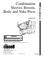
1
CSBBYMV
CAB438C
CAB438C
WARNING
Read and understand these instructions
before operating or servicing these machines.
Keep These Instructions for Future Reference.
(If this machine changes ownership, this manual must accompany machine.)
An LSG Company
831 South First Street, P.O. Box 32270
Louisville, KY 40232-2270
Phone: (502) 587-1292
Sales Fax: (502) 585-3625
Service/Parts Fax: (502) 681-1275
www.cissellmfg.com
Part No. AJ0976
March 2004
Installation
Combination
Sleever, Bosom,
Body and Yoke Press
Table of
Contents
Safety Information..............................................................................
Explanation of Safety Messages...........................................................
Important Safety Instructions ...............................................................
3
3
3
Operation.............................................................................................
Overall Dimensions and Connecting Data ...........................................
Dimensions and Specifications.............................................................
Utility Specifications ............................................................................
Electric .............................................................................................
Compressed Air ...............................................................................
Steam................................................................................................
Steam Return....................................................................................
Shipping Information .......................................................................
Materials Required...........................................................................
Receiving Inspection ............................................................................
Moving and Locating Press ..................................................................
Foundation Requirements.....................................................................
Uncrating ..............................................................................................
Anchoring and Leveling Press..............................................................
Items Shipped in Box............................................................................
Connecting Steam Supply and Returns ................................................
Connecting Air Service.........................................................................
Connecting Electrical Service...............................................................
Routing Blower Exhaust from Press.....................................................
Final Check-Out Procedures.................................................................
Buck Indexing Mechanical Check-Out............................................
Electrical Check-Out........................................................................
Steam Injection and Temperature Check-Out..................................
Break-In Adjustments ......................................................................
5
5
6
7
7
7
7
7
8
8
9
9
9
9
10
11
11
12
12
13
13
13
14
15
16
© Copyright 2004, Alliance Laundry Systems LLC
All rights reserved. No part of the contents of this book may be reproduced or transmitted in any form or by any
means without the expressed written consent of the publisher.
AJ0976
© Copyright, Alliance Laundry Systems LLC – DO NOT COPY or TRANSMIT
1
Notes
2
© Copyright, Alliance Laundry Systems LLC – DO NOT COPY or TRANSMIT
AJ0976
Safety Information
Explanation of Safety Messages
Important Safety Instructions
Precautionary statements (“DANGER,” “WARNING,”
and “CAUTION”), followed by specific instructions,
are found in this manual and on machine decals. These
precautions are intended for the personal safety of the
operator, user, servicer, and those maintaining the
machine.
Save These Instructions
DANGER
Indicates an imminently hazardous
situation that, if not avoided, will cause
severe personal injury or death.
WARNING
Indicates a hazardous situation that, if not
avoided, could cause severe personal
injury or death.
WARNING
Failure to install, maintain, and/or operate
this machine according to manufacturer’s
instructions may result in conditions
which can produce serious injury, death
and/or property damage.
NOTE: The WARNING and IMPORTANT
instructions appearing in this manual are not
meant to cover all possible conditions and
situations that may occur. It must be understood
that common sense, caution, and carefulness are
factors which CANNOT be built into this press.
These factors MUST BE supplied by the person(s)
installing, maintaining or operating the ironer.
Always contact your dealer, distributor, service agent,
or the manufacturer on any problems or conditions you
do not understand.
1. Read all instructions before using the press.
CAUTION
2. Refer to the GROUNDING INSTRUCTIONS in
the INSTALLATION manual for the proper
grounding of the press.
Indicates a hazardous situation that, if not
avoided, may cause minor or moderate
personal injury or property damage.
3. Do not allow children to play on or in the press.
Additional precautionary statements (“IMPORTANT”
and “NOTE”) are followed by specific instructions.
5. Do not install or store the press where it will be
exposed to water and/or weather.
IMPORTANT: The word “IMPORTANT” is used
to inform the reader of specific procedures where
minor machine damage will occur if the procedure
is not followed.
NOTE: The word “NOTE” is used to communicate
installation, operation, maintenance or servicing
information that is important but not hazard
related.
4. Do not reach into the press while the press is in
operation.
6. Do not tamper with the controls.
7. Do not repair or replace any part of the press, or
attempt any servicing unless specifically
recommended in the user-maintenance
instructions or in published user-repair
instructions that the user understands and has the
skills to carry out.
8. To reduce the risk of an electric shock or fire, DO
NOT use an extension cord or an adapter to
connect the press to the electrical power source.
9. Use press only for its intended purpose, finishing
garments.
10. ALWAYS disconnect the press from electrical
supply before attempting any service. Disconnect
the power cord by grasping the plug, not the cord.
AJ0976
© Copyright, Alliance Laundry Systems LLC – DO NOT COPY or TRANSMIT
3
Safety Information
11. Install the press according to the
INSTALLATION INSTRUCTIONS. All
connections for steam, electrical power and
grounding must comply with local codes and be
made by licensed personnel when required.
12. Replace worn power cords and/or loose plugs.
13. Never operate the press with any guards
and/or panels removed.
14. DO NOT operate the press with missing or
broken parts.
NOTE: The WARNINGS and IMPORTANT
SAFETY INSTRUCTIONS appearing in this
manual are not meant to cover all possible
conditions and situations that may occur. Common
sense, caution and care must be exercised when
installing, maintaining, or operating the press.
Any problems or conditions not understood should be
reported to the dealer, distributor, service agent or the
manufacturer.
15. DO NOT bypass any safety devices.
16. Failure to install, maintain, and/or operate this
press according to the manufacturer’s
instructions may result in conditions which can
produce bodily injury and/or property damage.
4
© Copyright, Alliance Laundry Systems LLC – DO NOT COPY or TRANSMIT
AJ0976
Operation
Overall Dimensions and
Connecting Data
2.75 in.
(70 mm)
BASE PAD (6 PLACES)
4 x 6 in. (102 x 152 mm)
ELECTRICAL
INLET
HEIGHT: 67 in. (1702 mm)
AIR INLET
1.375 in.
(35 mm)
4 in.
34 in.
(102 mm) (865 mm)
BASE
18.25 in.
(464 mm)
BASE
36.75 in.
(935 mm)
1.375 in.
(35 mm)
28 in.
(711 mm)
PLAN VIEW
MANUAL SPRAY
ASSEMBLY
STEAM IN AND
STEAM RETURN
LEFT END
GUARD
11 in.
(279 mm)
76 in.
(1932 mm)
AIR INLET
5.75 in.
(144 mm)
43 in.
(1091 mm)
20.63 in.
(525 mm)
103.88 in.
(2638 mm)
BASE
125.5 in.
(3188 mm)
1 in.
(25 mm)
STEAM INLET
4.13 in.
(106 mm)
2.75 in.
(76 mm)
5.38 in.
(134 mm)
10.88 in.
(272 mm)
34 in.
(864 mm)
BASE
RIGHT SIDE ELEVATION CAB414N
FRONT ELEVATION
CAB414N
Figure 1
AJ0976
© Copyright, Alliance Laundry Systems LLC – DO NOT COPY or TRANSMIT
5
Operation
Dimensions and Specifications
STANDARD BUCK – 18 in.
18 in.
(457 mm)
STANDARD, TAPERBODY, PULLOVER AND
STIFF BOSOM SHIRTS
36.875 in.
(937 mm)
SIZE 14-16
16 in.
(406.4 mm)
CAB687N
DIMENSIONS OF BUCK BEFORE PADDING IS APPLIED
NOTE: Actual pressing is 33.75 in. (318 mm) from top.
CAB84N
Figure 2
6
© Copyright, Alliance Laundry Systems LLC – DO NOT COPY or TRANSMIT
AJ0976
Operation
Utility Specifications
Electric
Voltage/Hertz/Phase
200/60/3
230/60/3
460/60/3
575/60/3
220/50/3
380/50/3
415/50/3
30.7
29.5
14.8
16.8
N/A
N/A
N/A
Circuit Breaker
50
50
25
30
N/A
25
25
Dual Element Fuse
60
60
30
35
N/A
30
30
24.5
23.6
11.8
13.4
N/A
11.8
11.8
19
18
9
10
N/A
9
9
3+ grd
3+ grd
3+ grd
3+ grd
3+ grd
3+ grd
3+ grd
N/A
N/A
N/A
N/A
N/A
Minimum Supply Circuit Conductor Ampacity
Maximum Rating of
Protection Device
Full Load Amps
Average Running Amperes
Number of Primary Power Connections
Wire Size
Motor
Sleeve Blower
Sidebag Blower
4 x 6 mm2 4 x 6 mm2
60 Hertz HP
60 Hertz RPM
50 Hertz HP
50 Hertz RPM
1
3450
N/A
N/A
4.6
3450
4.0
2875
Compressed Air
1/4 in. NPT Connection
(Clean, Dry Air Required)
Air Pressure
Minimum Free Air Consumption
Suggested Operating Pressure
U.S.A.
Metric
80 – 100 psig
5.6 – 6.9 bar
ft3/cycle
034 m3/cycle
1.2
65 psig
4.48 bar
Steam
1-1/4 in. NPT Connection
U.S.A.
Metric
Maximum Steam Pressure
125 psig
8.6 bar
Suggested Operating Pressure
110 psig
7.58 bar
Consumption @ 105 psig
86 lbs/hr
39 kg/hr
Steam Rating @ 105 psig
2.5 bhp
24.51 kW
Steam Return
1/2 in. NPT Connection (3 Places)
Flow-rate @ 100 psig
AJ0976
U.S.A.
Metric
86 lbs/hr
39 kg/hr
© Copyright, Alliance Laundry Systems LLC – DO NOT COPY or TRANSMIT
7
Operation
Shipping Information
U.S.A.
Metric
Length
111 in.
282 cm
Width
42 in.
107 cm
Height
82 in.
208 cm
Weight
2470 lbs.
1120 kg
NOTE: Applicable codes, ordinances, specifications
and/or other governing data related to installation
must be complied with. The materials listed in
Table 1 may or may not conform to these
requirements.
Materials Required
Quantity
Description
Source
1
Lockout type fused disconnect switch suitable for the electric service connected to
the press (refer to wiring schematic in control box) (not required if circuit breaker is
used)
Local
As required
Wire of suitable size, type and length to connect the electric service to the press
(refer to wiring schematic in control box)
Local
As required
Flexible conduit and connections to encase the wires and make connections
(refer to wiring schematic in control box)
Local
3
Steam trap and check valve, or combination steam trap/check valve sized steam
return lines and steam consumption
Local
3
Ball shut-off valves sized for steam supply, return lines and air supply
Local
Pipe, couplings, unions, flanges, etc., to connect steam supply and return lines and
air supply line to press. Wall thickness of pipe and tubing must be in compliance
with recommendations by compressor and boiler manufacturers and local code.
Local
5/8 in. anchor bolts
Local
As required
Machinery grout (if machine sits 1/2 in. [12.7 mm] or greater off of floor)
Local
As required
Pipe, couplings, unions, flanges, etc., to route air bag blower exhaust away from the
press
Local
As required
6
Table 1
8
© Copyright, Alliance Laundry Systems LLC – DO NOT COPY or TRANSMIT
AJ0976
Operation
Receiving Inspection
The press is shipped assembled and enclosed in a
plastic cover and crate. Upon delivery, inspect crate
and contents for shipping damage. If crate or cover is
damaged, or signs of possible damage are evident,
have carrier note the condition on the shipping papers
before shipping receipt is signed, or advise carrier of
condition when discovered.
Remove protective cover and check items received
against items listed on packing list. If any item is
damaged or missing, a written claim should be filed
with the carrier as soon as possible.
Moving and Locating Press
Uncrating
1. Remove wooden crate. Move the press to area of
final location and remove wooden skid. Remove
all panels.
WARNING
To avoid possible serious injury:
• ALWAYS be careful to AVOID springloaded components when working inside
press.
• Installation MUST be performed ONLY by
qualified service personnel.
W336
IMPORTANT: If a forklift is used to move the
press, exercise care that forklift arms are inserted
under the frame and do not contact any operating
mechanism.
Move press to the installation location while it is still
attached to skid. However, press can be removed from
skid before moving.
To remove unit from skid, unscrew the four shipping
cap screws from the attaching holes and work press
from skid.
Press should be located in an area that provides a
minimum of 24 inches (61 cm) between press and any
structure.
2. Install left end guard using attached hardware
before opening press heads. Refer to Figure 1 for
location if needed.
3. Remove any shipping material on heads and
buck.
4. Carefully remove any shipping braces using a
hammer or any long-handled striking device, to
knock shipping braces away from unit. Avoid
using excessive force to remove brace. Excessive
force applied to the braces can result in damage
to unit and/or alignment of internal parts.
IMPORTANT: The above dimensions are
considered minimum working and maintenance
dimensions and should be increased if possible.
Foundation Requirements
Install press on a solid, level floor such as concrete.
IMPORTANT: Installation on a wooden floor can
cause machine to shift, which will result in
misalignment of heads and bucks and damage to
both press and garments.
Floor should be capable of supporting 125 pounds
(56.7 kilograms) per square foot. Remove all floor
covering material (tile, wood, carpeting, etc.) from
press mounting area.
AJ0976
© Copyright, Alliance Laundry Systems LLC – DO NOT COPY or TRANSMIT
9
Operation
Anchoring and Leveling Press
Refer to Figure 3.
B
REMOVE ACCESS PANEL
TO INSTALL CENTER
LEVELING BOLT
RIGHT
LEVELING BOLTS
CENTER
LEVELING BOLTS
C
CENTER
LEVELING BOLTS
A
CAB85N
LEFT END
LEVELING BOLTS
CAB85N
Figure 3
1. Place machine in desired location.
2. Trace the 6anchoring holes onto the floor.
3. Move the press aside.
4. Drill the floor in all 6 places with a masonry bit
so that it will accept the 5/8"-11 expansion
anchors.
5. Insert 5/8"-11 expansion anchors into holes.
6. Using 5/8"-11 Grade 5 expansion bolts, expand
each anchor by turning the bolt into the anchor
until the bolt is secure and the anchor is fully
expanded.
10
7. Remove the bolts and reposition the machine
over the anchors.
IMPORTANT: Leveling the press is required.
Failure to follow leveling instructions can cause
misalignment of heads and buck and damage to the
press and garments, as well as void warranty.
8. Place a level across carriage rails at A and adjust
left end leveling bolts. Refer to Figure 3.
9. Move level to location B and adjust right end
leveling bolts. Refer to Figure 3.
© Copyright, Alliance Laundry Systems LLC – DO NOT COPY or TRANSMIT
AJ0976
Operation
10. Place level along inside carriage rail at C and
raise or lower either end of press as necessary.
Turn leveling bolts equal amounts to maintain
alignment at A and B.
Connecting Steam Supply and
Returns
11. Use a level to recheck A, B, and C.
NOTE: Clean out all pipe lines before connecting
them to the press.
12. Turn two center leveling bolts until they just
touch the floor.
13. Tighten leveling bolt jam nuts and bolt press to
floor.
14. Use a level to recheck A, B and C.
15. Install two 5/8" washers on each of the 5/8"-11
Grade 5 anchoring bolts.
16. Place anchoring bolts with washers into
expansion anchors.
17. Tighten all anchor bolts and torque to 80 ft./lbs.
18. Use grout if required.
IMPORTANT: Failure to properly install suitable
traps and check valves and supply correct steam
pressure will reduce operating efficiency.
Steam supply connected to press must have a constant
minimum pressure of 110 psi (7.58 bar).
The following steps outline the procedure for
connecting steam supply and return lines to press.
1. Run a 1-1/4 inch NPT steam line to the steam
supply connection with suitable black iron pipe,
elbows, strainer, ball valve and union.
IMPORTANT: A minimum 3 inch (7.62 cm) riser
should be installed off the supply header to
minimize water in the steam supply to the press.
Items Shipped in Box
A cardboard box is shipped inside press cabinet. It
includes:
●
Hi-temp lubricant
●
Installation and Operation Manuals
●
Eccentric wrench
NOTE: It is recommended that a steam strainer be
installed between the steam supply and press.
2. Install three suitable 1/2 inch NPT steam traps,
unions, check valves and ball valve between
steam return connections and steam return lines.
NOTE: Eccentric wrench will be used later for
adjusting buck carriage roller throughout life of
press. Keep hi-temp lubricant for maintenance.
MOUNTING HOLES
(6 PLACES)
0.8125 in. (21 mm)
7.75 in.
5 in.
(127 mm) (197 mm)
Refer to Figure 5.
NOTE: Cast iron inverted bucket traps are
recommended. Size traps according to steam
pressure and consumption found in Utility
Specifications.
AIR SUPPLY
(0.25 in. NPT)
UNION
3 in.
(76 mm)
STEAM
STRAINER
3 in. MIN.
28 in.
(711 mm)
12.25 in.
(311 mm)
17.75 in.
(451 mm)
RISER
BASE PADS
102 in.
(2591 mm)
65.25 in.
(1657 mm)
HEADER
STEAM LINE
(1.25 in. NPT)
CAB412N
STEAM TRAP
MOUNTING HOLES
CHECK VALVE
CAB412N
Figure 4
BALL VALVE
UNION
REQUIRED PIPING
HOOKUP BY CUSTOMER
CAB413N
CAB413N
Figure 5
AJ0976
© Copyright, Alliance Laundry Systems LLC – DO NOT COPY or TRANSMIT
11
Operation
Connecting Air Service
Air service connected to press must have a minimum
constant pressure of 75 psi (5.17 bar) and be of ample
volume to meet requirements listed in Utility
Specifications section. Air pressure should be reduced
to 65 psi (4.48 bar) at air inlet regulator. It is the
responsibility of the customer to connect the air line
with galvanized pipe, brass, aluminum or stainless
steel pipe, copper tubing, fittings, shut-off valve,
union, air filter and air dryer suitable for delivery of
clean, dry air to the inlet.
IMPORTANT: Failure to provide clean, dry air to
press will cause premature valve failure,
unnecessary downtime and void warranty.
NOTE: A shut-off valve and union placed at each
unit is recommended.
Connecting Electrical Service
WARNING
To avoid possible serious injury or death:
• ALWAYS shut off AND lock out ALL
electrical power to press BEFORE
performing electrical work.
W368
IMPORTANT: Improper connections will result in
equipment damage and will void the warranty.
1. Install a suitably sized fused disconnect switch or
circuit breaker as close to press as practical.
2. Remove one knockout plug from electrical
connection box.
3. Connect proper size conduit encased wires to
wires inside box.
4. Connect conduit to box.
NOTE: Refer to wiring schematic enclosed in
control panel for further details and instructions.
12
© Copyright, Alliance Laundry Systems LLC – DO NOT COPY or TRANSMIT
AJ0976
Operation
Routing Blower Exhaust from Press
Final Check-Out Procedures
Blower exhaust can add unwanted heat and noise into
a room. Route blower exhaust from press upward near
ceiling or to outside. Running exhaust outside is
recommended. If running exhaust outside, make sure
rain cannot get in.
NOTE: Refer to Operation Manual to identify
controls before performing the following checkouts.
Install exhaust piping from exhaust muffler as follows:
The following steps outline the procedure for buck
indexing mechanical check-out to the press:
1. Use coupling to connect minimum amount of
customer-provided 2-1/2 inch (6.35 cm) pipe
(schedule 80 CPVC, copper) to muffler 2 inch
(5.08 cm) pipe.
2. Run pipe to ceiling area or outside building.
Support pipe as required. The end of the pipe run
should be bell shaped and pointed downward to
avoid collecting debris.
IMPORTANT: Pipe must be adequately supported.
When using CPVC, support the pipe every 5 feet
(1.52 m).
Buck Indexing Mechanical Check-Out
WARNING
To avoid possible serious injury:
• BEFORE attempting to pull buck out of
cabinet,
ALWAYS shut off AND lock out ALL
electric, air and steam power to press
AND allow heated surfaces to cool
• ONLY USE ORANGE HANDLE to push
and pull buck IN and OUT of CABINET.
W439
NOTE: Use 45 degree bends wherever possible.
avoid 90 degree bends.
3. Exhaust can be routed into common header with
other presses. Header must be suitably sized.
Refer to Table 2.
NOTE: Bring pipe into header using Y tee. Angle
pipe so air is routed toward opening to atmosphere.
IMPORTANT: Undersized header WILL shorten
motor life and void warranty.
No. of Connections
Header Pipe Size
2
2-1/2 in. (6.35 cm)
3
3 in. (7.62 cm)
4
3-1/2 in. (8.89 cm)
5
4 in. (10.16 cm)
6
5 in. (12.70 cm)
1. Pull buck out to dressing position.
2. Turn on air to press and reset air circuit. Pressure
gauge should read line pressure 65 psi.
3. Step on the right foot pedal. Collar clamp should
open. Release the foot pedal and collar clamp
should close.
4. Step on the left foot pedal. Sleeve extender arms
should swing outward away from buck.
5. Press the sleeve extender release button. Sleeve
extenders should swing inward toward buck.
6. Simultaneously press and release both BUCK IN
buttons. Buck should travel into pressing position
inside the cabinet and heads close.
7. Check that the collar block is positioned in the
head cutout per Figure 6. If collar block is not
properly aligned, check press level. If press is
level, shim buck, adjust collar block or discharge
tube as necessary.
Table 2
AJ0976
© Copyright, Alliance Laundry Systems LLC – DO NOT COPY or TRANSMIT
13
Operation
Electrical Check-Out
1/8 in.
(3 mm)
Black and red electrical control buttons start and stop
all electrical functions.
1/8 in.
(3 mm)
1/8 in.
(3 mm)
1. Reset air to press per step 1 in Buck Indexing
Mechanical Check-Out. Turn electrical on to
press at fused disconnect switch or circuit
breaker.
2. Make sure Emergency Stop button is up if
applicable.
3. Press black start button.
NOTE: Start button will not start blower unless air
is reset to press.
CAB240N
Figure 6
8. Press the head release button. Heads should open
and buck should return to the dressing station.
9. Simultaneously press and release both buck in
buttons. As buck travels into cabinet, press red
safety bar which is near the operator. Buck travel
should stop, press heads should remain open and
air should exhaust from the system. Pressure
gauge should read 0 psi.
10. Reset air to press. Simultaneously press and
release both buck in buttons. Allow buck to travel
into cabinet and heads to close. Press other red
safety bar. Press heads should open, buck should
remain stationary and air should exhaust from the
system. Pressure gauge should read 0 psi.
WARNING
To avoid possible serious injury, NEVER
use press unless BOTH safety bars and
BUCK IN BUTTONS are working properly.
W369
11. Reset air to press. Simultaneously press and
release both buck in buttons. Allow buck to travel
into cabinet and heads to close. Press emergency
stop button. Press heads should open, buck
should remain stationary and air should exhaust
from the system. Pressure gauge should read
0 psi.
14
4. Check blower for proper rotation. Check airflow
direction at press muffler. Air should be
exhausting from muffler. If air is sucked in
toward muffler, change any two wires in the
electrical connection box.
5. Check isolation damper between sleeve heat
exchanger and blower. Air cylinder should extend
to open damper.
6. Step on left foot pedal. Vacuum should turn on to
buck. Press vacuum release button. Vacuum
should turn off to buck.
7. Set cycle timer selector switch to on position and
set pressing cycle timer for approximately
35 seconds. Turn steam timer selector switch to
off position. Send buck into pressing position.
Heads should close and remain closed for
approximately 35 seconds.
8. When press heads open, the buck should
automatically return to the dressing position.
9. Turn steam timer selector switch to the on
position. Set steam timer for 5 seconds. Send
buck into pressing position. Blower air should
blow through arm holes after a 5 second delay
and remain on until cycle timer times out.
10. After all checks (steps 1 through 9) are
completed, proceed with Steam Injection and
Temperature Check-Out.
© Copyright, Alliance Laundry Systems LLC – DO NOT COPY or TRANSMIT
AJ0976
Operation
Steam Injection and Temperature
Check-Out
WARNING
The following checks ensure that the steam supply to
the press is of sufficient temperature.
WARNING
To avoid possible serious injury or death,
perform the following BEFORE proceeding
to check out:
• Shut off AND lock out ALL electrical
power to press.
• Shut off AND lock out ALL air service to
press.
W370
Turn electrical power off.
1. Slowly open shut-off valves in both steam supply
and return lines.
2. Open needle valve at water gun assembly.
3. Allow press to heat for at least 15 minutes.
4. Check head surface temperature with pyrometer or
temperature stick measuring device. Temperature
should be 320° to 340°F (160° to 172°C).
5. Inspect all traps for proper operation per
manufacturer’s instructions.
AJ0976
To avoid possible serious injury, perform
the following BEFORE proceeding to
step 6:
• Make sure ALL motion has stopped.
• ALWAYS be careful to AVOID spring
loaded components when working inside
press.
• NEVER index buck while checking
temperature.
W371
6. Turn on air supply to press and reset air system.
Turn on electric power to press. Press black start
button. Blower will start. Allow press to heat for
an additional 5 minutes.
7. Turn both timers off.
8. Check temperature of air to yoke bag snorkel.
Send buck into pressing position. Remove plug
from tube at top of heat exchanger and insert
pyrometer to take air temperature reading.
Temperature should be 350°F (178°C).
IMPORTANT: Failure to perform the required
checks and make corrective actions could result in
damage to unit and void warranty.
© Copyright, Alliance Laundry Systems LLC – DO NOT COPY or TRANSMIT
15
Operation
Break-In Adjustments
As new press is used, working surfaces “seat-in” and
friction decreases. This usually results in increased
working speed.
These conditions are considered normal in a new press
and do not indicate a need for constant maintenance.
This initial “break-in” period will vary with usage, but
generally occurs during the first week of operation. At
this time the following items should be inspected and
adjusted if necessary.
1. Recheck the level of press. This is especially
important if press is located on wooden flooring.
2. Simultaneously press both buck in buttons to
send buck into cabinet and close heads. Check
alignment of collar block in head cutout. Check
snorkel alignment. Refer to Figure 6. Make
adjustments if required.
3. Adjust buck in travel speed. If buck is traveling
too fast or bottoms out shock absorber, slow
indexing cylinder down.
4. Check operation of all operating controls.
5. Inspect press for loose bolts, screws, pipe fittings
and carriage rollers, especially on the buck
carriage.
WARNING
To AVOID possible serious injury, BEFORE
performing maintenance or repair tasks:
• Shut off AND lock out ALL electric power
to the press.
• Shut off AND lock out ALL steam service
to the press.
• Allow heated surfaces to cool.
W334
16
© Copyright, Alliance Laundry Systems LLC – DO NOT COPY or TRANSMIT
AJ0976