1
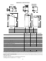
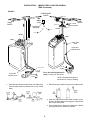
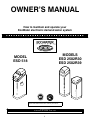
OWNER’S MANUAL
How to maintain and operate your
EcoWater electronic demand water system
R
MODELS
ESD 2502R30
ESD 2502R39
MODEL
ESD 518
Systems Tested and Certified by NSF International and WQA
against NSF/ANSI Standard 44 for softener performance.
EcoWater Systems
PO Box 64420, St. Paul MN 55164--- 0420
Part No. 7277268 (Rev. D 11/17/05)
PRINTED IN USA
1
GUARANTEE
BOND
LIMITED WARRANTY
EcoWater Systems LLC Advantage Warranty
Series ESD 518, ESD 2502R30
& ESD 2502R39 Water Systems
Congratulations! You have just purchased the highest quality water
conditioning product on the market. To register your warranty, complete the enclosed Warranty Registration Card and mail it within 30
days of purchase.
To whom is this warranty extended?
EcoWater Systems LLC warrants its products to the original owner and
guarantees that the products will be free from defects in materials and
workmanship from the original date of installation.
How does my warranty work?
If, during the respective warranty period, a part proves, after inspection
by EcoWater, to be defective, EcoWater will, at its sole option repair or
replace that part at no charge, other than normal shipping, installation
or service charges.
What is covered by the warranty?
EcoWater Systems LLC guarantees that,
for the LIFETIME of the original owner, the MINERAL TANK will not rust,
corrode, leak, burst, or in any other manner fail to perform its proper
function and that,
for a period of TEN YEARS, the SALT TANK will be free of defects in
materials and workmanship and will perform its proper function and
that,
for a period of THREE YEARS, the VALVE BODY, ELECTRONIC FACEPLATE and ALL OTHER PARTS will be free of defects in materials and
workmanship and will perform their normal functions.
How do I obtain warranty service?
Should you need service, your local, independent EcoWater Dealer is
only a phone call away.
PHONE:
The Safeco Insurance Company of America has issued it’s
bond in the form shown below, guaranteeing full performance
by EcoWater Systems LLC
SAFECO INSURANCE COMPANY OF AMERICA, hereinafter
called ‘‘Surety,’’ guarantees unto Bank of New York as Trustee
holding said Guarantee Bond under the terms of a Trust Agreement dated April 9, 2003, for the use and benefit of original purchasers of residential EcoWater Systems Units within the Continental United States, as described herein, that EcoWater
Systems LLC, will discharge the obligations of the ‘‘EcoWater
Bonded Parts and Service Guarantee Policy.’’
PROVIDED, HOWEVER, that:
1. Liability of Surety hereunder shall not exceed the sum of FIVE
HUNDRED AND 00/100th DOLLARS ($500.00) as to any one
installation, and shall not exceed the sum of FIVE HUNDRED
THOUSAND AND 00/100th DOLLARS ($500,000.00) in the
aggregate, and
2. There shall be no liability hereunder as to any purchaser to
whom there has not been issued at the time of installation and
purchase completed registration card which is enclosed with a
facsimile of this bond, and who has not returned such card in
accordance with this guarantee.
To obtain warranty service, notice must be given, within thirty (30) days
of the discovery of the defect, to your local EcoWater Systems dealer.
If I need a part replaced after the factory warranty expires, is the
replacement part warranted?
Yes, EcoWater Systems LLC warrants FACTORY REPAIRS as well as
all REPLACEMENT PARTS for a period of 90 DAYS. This warranty does
not include normal shipping, installation or service charges.
Are any additional warranties available?
We are pleased to say, YES! EcoWater Systems LLC sells an EXTENDED, PARTS ONLY WARRANTY for the ELECTRONICS portion of
your product. This warranty is called the “Perfect Ten” and extends the
three year warranty on the electronic FACEPLATE, WIRING HARNESS, DRIVE MOTOR, TRANSFORMER, POWER CORD, SENSOR
HOUSING, and MICRO SWITCHES to a total of TEN YEARS from the
date of original installation. Your local dealer will provide details regarding this warranty or will refer you to the factory for additional information.*
General Provisions
The above warranties are effective provided the water conditioner is
operated at water pressures not exceeding 125 psi, and at water temperatures not exceeding 120°F; provided further that the water conditioner is not subject to abuse, misuse, alteration, neglect, freezing, accident or negligence; and provided further that the water conditioner
is not damaged as the result of any unusual force of nature such as,
but not limited to, flood, hurricane, tornado or earthquake. EcoWater
Systems LLC, is excused if failure to perform its warranty obligations
is the result of strikes, government regulation, materials shortages, or
other circumstances beyond its control.
*THERE ARE NO WARRANTIES ON THE WATER CONDITIONER BEYOND THOSE SPECIFICALLY DESCRIBED ABOVE. ALL IMPLIED
WARRANTIES, INCLUDING ANY IMPLIED WARRANTY OF MERCHANTABILITY OR OF FITNESS FOR A PARTICULAR PURPOSE, ARE
DISCLAIMED TO THE EXTENT THEY MIGHT EXTEND BEYOND THE
ABOVE PERIODS. THE SOLE OBLIGATION OF ECOWATER SYSTEMS LLC UNDER THESE WARRANTIES IS TO REPLACE OR REPAIR THE COMPONENT OR PART WHICH PROVES TO BE DEFECTIVE WITHIN THE SPECIFIED TIME PERIOD, AND ECOWATER IS
NOT LIABLE FOR CONSEQUENTIAL OR INCIDENTAL DAMAGES.
NO ECOWATER DEALER, AGENT, REPRESENTATIVE, OR OTHER
PERSON IS AUTHORIZED TO EXTEND OR EXPAND THE WARRANTIES EXPRESSLY DESCRIBED ABOVE.
Some states do not allow limitations on how long an implied warranty
lasts or exclusions or limitations of incidental or consequential damage, so the limitations and exclusions in this warranty may not apply
to you. This warranty gives you specific legal rights, and you may have
other rights which vary from state to state. This warranty applies to consumer ---owned installations only.
3. Claim must be made by such original purchaser in writing
within 30 days from the expiration of these guarantees upon
EcoWater Systems LLC, PO Box 64420, St. Paul, MN 55164,
to perform the terms of said guarantee, and notice of any default
on such guarantee must be sent to Surety at its address by
Registered Mail.
SAFECO INSURANCE COMPANY OF AMERICA
This is to certify that the original of the above guarantee and
bond is on file with Bank of New York.
BANK OF NEW YORK
As Trustee
2
SAFETY GUIDES
Follow the installation instructions carefully. Failure to install the EcoWater softener properly voids the warranty.
Before you begin installation, read this entire manual. Then, obtain all the materials and tools you will need
to make the installation.
Check local plumbing and electrical codes. The installation must conform to them. In Massachusetts,
plumbing codes of Massachusetts shall be adhered to. Consult with your licensed plumber.
Use only lead -- free solder and flux for all sweat---solder connections, as required by state and federal
codes.
Use care when handling the EcoWater softener. Do not turn upside down, drop, or set on sharp protrusions.
Do not locate the EcoWater softener where freezing temperatures occur. Do not attempt to treat water over
120˚F. Freezing, or hot water damage voids the warranty.
Avoid installing in direct sunlight. Excessive sun heat may cause distortion or other damage to non---metallic
parts.
The EcoWater softener requires a minimum water flow of 3 gallons per minute at the inlet. Maximum allowable inlet water pressure is 125 psi. If daytime pressure is over 80 psi, nighttime pressure may exceed the
maximum. Use a pressure reducing valve if necessary. (Adding a pressure reducing valve may reduce the
flow.)
The EcoWater softener works on 24 volt -- 60 hz electrical power only. Be sure to use the included transformer and plug it into a nominal 120V, 60 cycle household outlet that is grounded and properly protected by
an overcurrent device such as a circuit breaker or fuse. If transformer is replaced, use only the authorized
service Class II, 24 volt, 10 VA transformer.
This system is not intended to be used for treating water that is microbiologically unsafe or of unknown quality
without adequate disinfection before or after the system.
European Directive 2002/96/EC requires all electrical and electronic equipment to be disposed of according to Waste Electrical and Electronic Equipment (WEEE) requirements. This directive or similar
laws are in place nationally and can vary from region to region. Please refer to your state and local laws
for proper disposal of this equipment.
3
DIMENSIONS / SPECIFICATIONS
ESD 518
OUT
A
ESD 2502R30
ESD 2502R39
IN
20”
IN
14”
A
16”
14”
OUT
14”
IN --- OUT
16”
IN --- OUT
C
C
B
36--- 9/16”
32”
B
32--- 1/2”
MODEL
NOMINAL RESIN TANK SIZE
A
B
C
ESD 518
8” DIA. X 35”
3--- 3/8”
38--- 1/8”
45”
ESD 2502R30
8” DIA. X 40”
3--- 3/8”
41.6”
48.75”
ESD 2502R39
10” DIA. X 47”
3--- 3/4”
49.8”
56.6”
Rated Capacity (grains @ salt dose)
Service Flow Rate (gpm)
ESD 518
ESD 2502R30
ESD 2502R39
10,100 @ 2.0 lbs
21,500 @ 6.4 lbs
25,600 @ 10.7 lbs
12,200 @ 2.4 lbs
25,600 @ 7.5 lbs
30,600 @ 12.6 lbs
12,100 @ 2.4 lbs
31,700 @ 8.9 lbs
40,200 @ 15.4 lbs
5.0
7.8
7.0
Pressure Drop at Service Flow Rate (psi)
7
15
6
Intermittent Flow Rate (gpm) @ 15 psi ✦
8.7
7.8
13.3
Intermittent Flow Rate (gpm) @ 30 psi ✦
13.5
12.2
20.9
5030 @ 2.0
5070 @ 2.4
5030 @ 2.4
Amount of High Capacity Resin (cu ft)
.67
.79
1.13
Water Supply Max. Hardness (gpg)
50
60
80
Water Supply Max. Clear Water Iron (ppm) ◓
3
4
5
Rated Efficiency (gr / lb of salt @ min. salt dose) ◪
Water Pressure Limits (min./max. psi) ◮
20 -- 125
Min./Max. Water Temperature (˚F)
40_ -- 120_
Min. Water Supply Flow Rate (gpm)
3
Max. Drain Flow Rate (gpm)
2.0
2.0
2.3
These systems conform to NSF/ANSI 44 for the specific capacity claims as verified and substantiated by test data.
✦ Intermittent flow rate does not represent the maximum service flow rate used for determining the softeners rated capacity and efficiency. Continuous operation at flow rates greater than the maximum service flow rate may affect capacity and efficiency performance. The
validity of these flow rates is verified by NSF.
◪ Efficiency rating is only valid at the minimum stated salt dose and service flow rate. These softeners were efficiency rated according
to NSF/ANSI standard 44.
◓ Capacity to remove clear water iron is substantiated by WQA test data.
◮ Working pressure for Canadian use is 1.4 -- 7.0 kg/cm@.
4
INSTALLATION -- (MODELS ESD 518 & ESD 2502R30)
(ESD 518 shown)
FIGURE 1
CONDITIONED
WATER
bypass valve
120V,
60Hz
outlet
HARD
WATER
HARD
WATER
3--- valve
bypass system
outlet valve
transformer
(supplied)
to timer
OUTLET
OUTLET
inlet valve
to timer
INLET
INLET
valve drain
hose
brine tank
overflow hose
1---1/2”
airgap
valve drain hose
1---1/2”
airgap
brine tank
overflow hose
Tie or wire valve drain hose in
place, to keep over floor drain.
floor drain
NOTE: Faceplate and support
not shown for clarity of drawing.
floor drain
1. Close the shut off valve on the house main water pipe,
near the water meter or pressure tank, to turn off the
water.
2. Shut off the gas or electric supply to the water heater.
3. Open the highest and lowest water faucets in your
house to let water drain from the pipes. Close faucets
after water has drained.
4. If not already done, remove all cardboard or plastic
packing pieces from inside the softener.
5
INSTALLATION (continued) -- (MODELS ESD 518 & ESD 2502R30)
5. INSTALL INLET AND OUTLET ADAPTORS, OR
THE OPTIONAL BYPASS VALVE.
7. Referring to page 5, run inlet and outlet pipes to the
softener, observing all of the following notes.
H
If the optional bypass valve is not used, be sure to
use a three valve bypass as typically shown in Figure
1. Position in “bypass” only if needed for softener repairs. The bypass valve maintains continuity of the
water supply when the softener is disconnected.
H
Be sure to plumb so HARD WATER flows TO the softener valve INLET.
H
If sweat soldering, first disconnect copper pipes from
plastic softener parts. DO NOT SOLDER WITH
COPPER CONNECTED TO THE SOFTENER OR
PLASTIC PARTS WILL BE DAMAGED.
BYPASS VALVE --- Push the bypass valve into the
valve ports (can be inverted for connecting to floor
level plumbing). Be sure the o---ring seals are lubricated with silicone grease or Vaseline.
H
If using threaded fittings, use extreme care not to
cross thread onto plastic.
H
Support inlet and outlet plumbing in some manner,
to keep the weight off of the softener valve.
SNAP THE TWO LARGE HOLDING CLIPS INTO
PLACE, FROM THE TOP DOWN AS SHOWN. BE
SURE THEY SNAP FIRMLY INTO PLACE, SO THE
ADAPTORS, OR BYPASS VALVE, DO NOT PULL
OUT.
8. CONNECT THE VALVE DRAIN HOSE
IMPORTANT: Be sure the
turbine, turbine support
and sensor housing are
firmly in position, in or on
the valve outlet.
H
INLET AND OUTLET ADAPTORS --- Push adaptors
into the valve ports. Be sure the o---ring seals are lubricated with silicone grease or Vaseline.
-- OR--
H
Attach a length of 3/8” I.D. hose to the valve drain fitting. Use a hose clamp to hold it in place. Place the
other end of the hose over a floor drain, laundry tub,
sump, standpipe or other suitable drain. BE SURE
TO OBSERVE LOCAL CODES.
FIGURE 2
drain fitting
hose clamp
IMPORTANT NOTES:
Leave an air gap of about 1---1/2” between the end of the
hose and the drain. This gap is needed so you don’t get
a back ---flow of sewer water into the softener. DO NOT
put the end of the hose into the drain or connect without
the air gap.
Place and support the hose so it does not kink or have
sharp bends. Tie or wire the hose in place so water pressure will not make it “whip”. Do not pinch the hose shut.
THE SOFTENER WILL NOT WORK IF THIS DRAIN HOSE
IS PINCHED, PLUGGED OR CLOSED IN ANY WAY.
6. Move the softener into installation position, setting on
a smooth and level surface. If needed, set it on a
piece of 3/4” thick plywood (slightly larger than the
bottom of the brine tank). Then shim under the plywood to level the softener.
Keep the hose lower than the drain fitting. In some
homes, to get to a drain you must raise the hose and run
it over head. If you need an overhead drain, do not raise
the hose more than 8’ above the floor.
6
BRINE TANK ASSEMBLY -- (MODELS ESD 2502R30 & ESD 2502R39)
Note: On some models, the factory may complete steps
1 and 2 below.
1. Locate the brinewell in position and secure with a
screw and nut (from parts skin---pack).
FIGURE 3
nut
brinewell cover
compression nut
2. Lower the brine valve into the brinewell and install the
brinewell cover.
brine tubing
3. Insert the grommet into the hole in the tank sidewall.
Then, push the hose adaptor elbow into the grommet.
brine tank
4. Continue with step 6., on page 8.
grommet elbow
screw
brine valve
brinewell
INSTALLATION -- (MODEL ESD 2502R39)
BE SURE TO READ AND COMPLY WITH ALL GUIDES LISTED ON PAGE 3.
1. Install the installation adaptors, or the optional bypass valve (Figure 4). Be sure clips hold parts firmly
in place. Pull on the adaptors or bypass valve to insure they are secure.
2. Run the hard water supply to the valve inlet, and
conditioned water out from the valve outlet.
CAUTION: Do all soldering, and allow to cool, before
connecting pipe to the adaptors or bypass valve.
3. Install the ground clamp if cold water pipe ground
continuity was interrupted.
Note: If the optional bypass valve is not used, be sure to
install a 3---valve bypass (Figure 5).
clip (2)
FIGURE 4
FIGURE 5
copper tubes (install in softener valve or bypass valve)
OUTLET
Bypass Valve
hard water to
outside faucets
soft water
hard water
INLET
clip (2)
Outlet Valve
bypass
valve
Inlet Valve
GROUND CONTINUITY
OUT
ground
clamp
IN
clip
Soldered copper, threaded, or
PVC plastic pipe and fittings.
Plumb to copper tubes. Eliminate 3 valves shown above if using optional bypass.
to valve
inlet
from valve
outlet
copper tube
o--ring seal
Valve Inlet
7
INSTALLATION (continued) -- (MODEL ESD 2502R39)
4. Run the valve and brine tank overflow drain hoses
(Figure 6). Secure the valve drain hose to the drain fitting with the included hose clamp. Provide a minimum 1---1/2” air gap at the floor drain, standpipe,
laundry tub, or other approved drain. If you need to
elevate the valve drain hose to get to the drain point,
do not raise more than 8’ above the floor. The gravity
overflow hose must be lower than the drain fitting
along the entire run.
FIGURE 6
compression nut
screen
brine tubing
nozzle assembly
brine tubing
valve drain
hose
Note: Flexible drain hose is not allowed by some state or
local codes. A fitting (1/4” NPT x 1/2” O.D. tube, part no.
0504574) is available from EcoWater for adapting copper
tubing to the valve drain fitting.
5. Route the brine valve tubing out of the brine tank and
connect to the nozzle assembly. Use the small screen
and compression nut included (on skin---pack) to fasten.
6. Connect the power cable to the transformer and plug
into a 120V --- 60Hz electrical outlet.
WIRING
SCHEMATIC
brine tank
overflow hose
floor drain
1---1/2”
airgap
7. Open nearby faucets and advance (use RCHG
keypad) the softener valve to backwash position
to vent air from the tank. Turn on the water supply
and allow the softener to fill. When water at nearby
faucets runs smooth, with no more air bubbles, close
the faucets and advance the softener valve to ‘‘service’’.
BACK OF
FACEPLATE TIMER
24V
TRANSFORMER
120 V
Power
Source
8. Check your installation work for leaks.
9. Make all timer settings, page 9.
VALVE
MOTOR
10. Sanitize the unit following procedures below, and use
‘‘Recharge Now’’ to start a recharge.
brn
POSITION
SWITCH
11. Fill the brine tank with salt. You may use most water
conditioner salts, but it must be clean. Recommended nugget, pellet or course solar salts have less
than 1% impurities.
grn
WATER METER
SENSOR HOUSING
12. Install the brine tank cover.
DISINFECTING THE SOFTENER
Care is taken at the factory to keep your softener clean and sanitary. Materials used to make the unit will not
infect or contaminate your water supply, and will not cause bacteria to form or grow. However, during shipping,
storage, installing and operating, bacteria could get into the unit. For this reason, sanitizing as follows is suggested when installing.
1. Use a pail or hose to fill the brine tank with about 3 gallons of water.
2. Remove the brinewell cover and pour about 1---1/2 oz. (2 to 3 tablespoons) of common household bleach
into the softener brinewell. Clorox, Linco, BoPeep, White Sail, Eagle, etc. are brand names of bleach readily
available. Replace the brinewell cover.
3. Start an automatic regeneration to draw the bleach into and through the softener, and to the drain.
Note: When the sanitizing regeneration is over all remaining bleach is flushed from the system.
8
FIGURE 7
UP keypad
display
RECHARGE keypad
DOWN keypad
SELECT keypad
When the transformer is plugged in, a model code shows
in the face plate display for the first few seconds. The
model code for your water softener is S518, S30 OR H40,
as shown in the following drawing. The model code is followed by a test number (example: J1.0). After the test
number, 12:00 PM begins to flash. The words PRESENT
TIME show in the display.
If the present time is between noon
and midnight, be sure PM shows.
If the present time is between midnight
and noon, be sure AM shows.
Model
ESD 518
NOTE: Each press of the UP or DOWN keypads changes
the time by 1 minute. Pressing and holding the keypads
changes the time 32 minutes each second.
2. SET WATER HARDNESS NUMBER:
Model
ESD 2502 R30
Press the SELECT keypad once to display 25 (flashing) and HARDNESS.
Set the grains per gallon hardness of
your water supply (determined by water analysis or call your local water department).
Model
ESD 2502 R39
NOTE: If --- --- --- --- is flashing in the display, press the UP
(↑) keypad (Figure 7) until the correct code shows, as
needed for your model. Be sure to set the correct code.
Then, press the SELECT keypad to display the flashing
12:00 PM. If other than the above codes show, when
the transformer is first plugged in, please see page 13 to
reset.
NOTE: If your water supply contains iron, compensate
for it by adding to the water hardness number. For example, assume your water is 15 gpg hard and contains 2
ppm iron. Add 5 to the hardness number for each 1 ppm
of iron. In this example, you would use 25 for your hardness number.
SOUND “BEEPER”: A “beeper” sounds while pressing
keypads for timer set-up. One beep signals a change in
the face plate display. Repeated beeps means the timer
will not accept a change from the keypad you have
pressed, telling you to use another keypad. For example,
in setting the hardness (step 2), the beeper sounds repeatedly when the display reaches 1 using the DOWN
keypad, or the highest hardness setting using the UP
keypad.
2 ppm iron x 5 = 10
(times)
15 gpg hardness
+10
25 HARDNESS NUMBER
Press the (↑) UP/DOWN (↓) keypads to set your water
hardness number in the display. The DOWN keypad
moves the display to 1. The UP keypad moves the display to the highest setting (see maximum setting for your
model in the specifications).
NOTE: If the words PRESENT TIME do not show in the
display, press the SELECT keypad (Figure 7) until they
do.
NOTE: Each press of the UP/DOWN keypad changes the
display by 1 between 1 and 25. Between 25 and the highest number, the display changes 5 at a time 25, 30, 35,
etc. Continuous pressure on the UP or DOWN keypad
changes the display twice each second.
Press the (↑) UP/DOWN (↓) keypads to set the present
time. Press UP to move the display ahead; press DOWN
to move the time backward.
NOTE: If using potassium chloride (KCl) instead of standard sodium chloride (NaCl) water softener salt, hardness setting must be increased by 25%.
1. SET PRESENT TIME OF DAY:
9
3. SET RECHARGE (REGENERATION) TIME:
NOTE: California regulations require the efficiency setting to be ON for sale in California.
Press the SELECT keypad once to display 2:00 AM
(flashing) and RECHARGE TIME.
At the 2:00 AM RECHARGE TIME setting, the softener begins regeneration
at 2:00 AM, ending no later than 4:00
AM. This is a good time in most households because water is not being used.
NOTE: When efficiency setting is set to
on, an icon will show in the upper right
hand corner of the display.
Press the SELECT button once to go to the backwash
time setting.
If a different RECHARGE TIME setting would be better for
your household, do the following.
NOTE: Factory default for this setting is
7 minutes.
Press the (↑) UP/DOWN (↓) keypads to set the desired
RECHARGE starting hour. Be sure to observe the AM-PM
as you did when setting the time of day.
Press the UP or DOWN button to set the desired backwash time.
NOTE: Each press of the UP/DOWN keypads changes
the display 1 hour. Continuous pressure on the UP or
DOWN keypad changes the display twice each second.
Press the SELECT button once to go to the rinse time setting.
NOTE: Factory default for this setting is
3 minutes.
4. SET EFFICIENCY, BACKWASH TIME AND
RINSE TIME:
Press the SELECT keypad once again, to return the
present time (steady) of day.
Press and hold the SELECT button.
“000--- ---’” should show in display.
Press SELECT button once more to go
to Efficiency screen.
Press the UP or DOWN button to set the efficiency setting
either on or off.
CALIFORNIA EFFICIENCY REQUIREMENT
Your water softener has a “High Efficiency” feature with an “ON” or “OFF” setting. This softener setting is shipped
in the “OFF” position, which utilizes the maximum rated capacity while most often achieving maximum salt
efficiencies. When installing this unit in the State of California, you MUST turn this setting to the “ON” position
which may initiate more frequent recharges, however it will operate at 4000 grains per pound of salt or higher.
If you wish to turn the Salt Efficiency feature “ON” (
page.
icon will show in display), follow the instructions on this
10
EXTRA RECHARGE
play is flashing. The HARDNESS and RECHARGE TIME
never require resetting unless a change is desired.
Even if the timer is incorrect after a long power outage,
the softener works as it should to keep your water soft.
However, regenerations may occur at the wrong time of
day until you reset the timer to the correct time of day.
Sometimes, a manually started regeneration (recharge)
may be desired, or needed. Two examples are:
. You have used more water than usual (guests visiting)
and you may run out of soft water before the next timer
started regeneration.
ERROR CODE
. You did not refill the softener with salt before it was
gone.
An error code could appear in the face
plate display if a problem occurs in the
softener electronics.
You can start a regeneration right away, or you can set
the timer to regenerate at the next 2:00 AM (or other preset recharge time). Do the following.
WATER METER:
RECHARGE NOW
The water meter, consisting of a turbine, turbine mounting assembly, and the sensor housing, is located at the
valve outlet port. As water passes through and spins the
turbine, two magnets (in the turbine) cause a back --and---forth movement of a switch in the sensor housing.
This switch movement sends a pulse to the electronic demand timer.
Press the RECHARGE keypad and
hold for 3 seconds. RECHARGE NOW
begins to flash in the display, and the
softener enters the fill cycle of regeneration right away. This regeneration will last for about 2
hours. Then, you will have soft water again.
RECHARGE TONIGHT
ELECTRONIC DEMAND TIMER:
Press and release (do not hold) the
RECHARGE keypad. RECHARGE TONIGHT flashes in the display, and the
softener begins regeneration at the
next preset recharge time. If you decide to cancel the regeneration before it has started, press and release the
RECHARGE keypad once more to turn off the flashing
RECHARGE TONIGHT.
The demand timer is actually a small computer. As it receives pulses from the water meter, it converts them to
gallons of water passing through the water softener. It
multiplies this water usage information times the water
hardness (preprogrammed into timer) to continually calculate the soft water capacity required. The computer adjusts daily to water using habits, seeking to supply soft
water for the longest time, using the least (and most efficient) amount of salt and water to regenerate.
When the computer determines more capacity is needed, at the next regeneration starting time (2:00 a.m., or
as otherwise preset), it will schedule a regeneration. RECHARGE TONIGHT shows in the display to inform of the
coming regeneration.
PROGRAM MEMORY
If electrical power to the softener goes off, the time display is blank but the face plate timer keeps the correct
time for about 6 hours. When electrical power comes on
again, you have to reset the present time only if the dis-
11
REFILLING WITH SALT
CLEANING THE NOZZLE AND VENTURI
A clean nozzle and venturi (Figure 8) is a must for the
EcoWater System Unit to work right. This small unit
creates the suction to move brine from the brine tank, into
the resin tank. If it should become plugged with sand, silt,
dirt, etc., the EcoWater System Unit will not work, and
you will get hard water.
To get to the nozzle and venturi, remove the EcoWater
System Unit top cover. Be sure the unit is in service
cycle (no water pressure at nozzle and venturi). Then,
holding the nozzle and venturi housing with one hand,
turn off the cap. Do not lose the o ---ring seal. Lift out the
screen support and screen. Then, remove the nozzle and
venturi. Wash the parts in warm, soapy water and rinse
in fresh water. If needed, use a small brush to remove iron
or dirt. Be careful not to scratch, misshape, etc., surfaces
of the nozzle and venturi. Also, check and clean the gasket and flow plug(s) if dirty.
Carefully replace all parts in the correct order. Lubricate
the o---ring seal with silicone grease and locate in position. Install and tighten the cap, by hand only. Do not
overtighten and break the cap or housing.
Remove the brine tank cover and check the salt storage
level frequently. If the unit uses all the salt before you refill
it, you will get hard water. Until you have established a
refilling routine, check the salt every 2 or 3 weeks. ALWAYS refill if less than 1/2 full. Be sure the brinewell cover is on.
RECOMMENDED SALT: Cube, pellet, coarse solar, etc.,
water conditioner salt is recommended. This type of salt
is from high purity evaporated crystals, sometimes
formed, or compressed, into briquets. It has less than 1%
insoluble (will not dissolve in water) impurities. Clean,
high grade rock salts are acceptable, but may require
frequent brine tank cleaning to remove the ‘‘sludge’’ residue (insolubles). NOTE: If using potassium chloride
(KCl) instead of standard sodium chloride (NaCl) water
softener salt, hardness setting must be increased by
25%.
SALT NOT RECOMMENDED: Rock salt, high in impurities, block, granulated, table, ice melting, ice cream making salts, etc., are not recommended.
FIGURE 8
SALT WITH IRON REMOVING ADDITIVES: Some salts
have an additive to help a water conditioner handle iron
in a water supply. Although this additive may help keep
the resin bed clean, it may also release corrosive fumes
that will weaken and shorten the life of some EcoWater
System Unit parts.
BREAKING A SALT BRIDGE
Sometimes, a hard crust or salt bridge forms in the brine
tank. It is usually caused by high humidity or the wrong
kind of salt. When the salt bridges, an empty space forms
between the water and the salt. Then, salt will not dissolve in the water to make brine. Without brine, the resin
bed does not regenerate and you will have hard water.
If the storage tank is full of salt, it is hard to tell if you have
a salt bridge. Salt is loose on top, but the bridge is under
it. Take a broom handle, or like tool, and push it straight
down into the salt. If a hard object is felt, it’s most likely
a salt bridge. Carefully push into the bridge in several
places to break it.
NOTE: In humid areas, it is best to keep the salt storage
level lower, and to refill more often.
12
RESIN BED CLEANING
FIGURE 9
plug distributor tube
while adding resin
If the water supply contains ‘‘clear water ’’ iron (see page
9), regular resin bed cleaning is needed to keep the bed
from coating with iron. Use resin bed cleaner, available
from EcoWater, following directions on the container.
Clean the resin every 6 months, or more often if iron appears in your conditioned water supply.
add resin
FREEBOARD
ADDING RESIN
resin
tank
bottom
distributor
tube
resin
bed
Normally, the resin bed (Figure 9) will last the lifetime of
the EcoWater System Unit. However, certain conditions
may require partial or total replacement of the resin bed.
Some of these conditions are:
IMPORTANT NOTES:
Turn off the water supply and relieve pressure.
(1) damaged top and/or bottom distributors have allowed resin to escape
(2) resin bed iron fouled beyond use
(3) some water supplies cause resin degradation
Handle the resin tank carefully. It is heavy when filled with
resin and water.
Do not lose o---ring seals or other small parts.
Refer to the assembly instructions and to installation
steps to reassemble and restart the unit.
To add more resin, or to replace the entire bed, use the
following guides. See resin requirements on page 4.
CHECKING THE MODEL CODE ENTRY (See page 9)
Unplug the transformer at the electrical outlet, then plug it in again. A “beep” will sound, then the model code displays
for a few seconds. The test number will then display for a few seconds, followed by the present time display.
CHANGING THE MODEL CODE
IMPORTANT: READ page 9 BEFORE CHANGING THIS CODE.
1. Enter the secondary mode...press SELECT and hold for 3 seconds.
2. Again, press SELECT and hold for 3 seconds. The current model code setting will be flashing.
3. Use the (↑) or (↓) keypad to display the desired model code.
4. Press SELECT to set.
5. Reset the timer (page 9) and reselect other desired options.
13
REPAIR PARTS -- ALL MODELS
Valve Assembly
(see pages 16 --- 19 )
1
2
38
39
40
19
20
21
22
25
23
3
6
24
37
4
36
26
29
5
35
27
7
30
34
8
33
28
31
32
41
2
9
10
5
11
12
10
9
13
12
8
13
14
16
14
15
16
17
11
18
15
17
14
REPAIR PARTS -- ALL MODELS
KEY
NO.
PART
NO.
KEY
NO.
PART
NO.
1
7252373
2
7218662
Transformer, 24V--- 10VA
23
7105047
Repl. Distributor (bottom)
Top Cover (ESD 518)
24
7176292
Clamp Section, 2 req.
7218670
Top Cover (ESD 2502 models)
25
7088033
Clamp Retainer, 2 req.
26
7114787
Resin Tank, 8” dia. x 35”, ESD 518
7113058
Resin Tank, 8” dia. x 40”, ESD 2502R30
7092202
Resin Tank, 10” dia. x 47”, ESD 2502R39
0502272
Resin, 1 cu ft (stand. mesh)
DESCRIPTION
DESCRIPTION
3
7210509
Faceplate (order following decal)
---
7214692
Decal
4
7238418
Repl. PWA
5
7211173
Faceplate Support
6
7210389
Salt Hole Cover (ESD 518)
0501741
Resin, 1/2 cu ft (stand. mesh)
7
7214244
Vapor Barrier (ESD 518)
28
1184700
Spacer (ESD 518, ESD 2502R30)
8
7210397
Rim (ESD 518)
29
7113008
Float, Stem and Guide Assem.
7210460
Rim (ESD 2502 models)
30
7170288
O --- ring, 15/16” x 1--- 3/16”
27
9
7155115
Brinewell Cover
31
1205500
Clip
10
7219595
Washer
32
7092252
Brine Valve Body
11
7109871
Brinewell
33
7080653
Clip
12
9003500
Grommet
34
7131365
Screen
13
1103200
Hose Adaptor
35
7113016
Tubing Assembly, BV
14
0900431
Hose Clamp
36
7095470
Brine Tube
15
7219587
Screw
37
7171349
Screen
16
7218604
Brine Tank (ESD 518)
38
9003201
Nut--- Ferrule, 2 req. =
7218612
Brine Tank (ESD 2502 models)
39
7161807
Tubing, 20 ft =
17
7141205
Tank Base
---
7161768
Tubing, 100 ft
18
7218620
Resin Tank Sleever (ESD 2502R30)
40
7094987
Union Connector =
7218646
Resin Tank Sleever (ESD 2502R39)
41
7210486
Brine Tank Cover (ESD 2502 models)
19
7170296
O --- ring Seal, 2--- 7/8” x 3--- 1/4”
J
7116488
Brine Valve Asm (incl. Key Nos. 29 --- 36)
20
7170254
O --- ring, 13/16” x 1--- 1/16”
J
7108118
Hose, 1/2” I.D. Drain (order length needed)
21
7077870
Top Distributor
22
7170270
O --- ring, 2--- 3/4” x 3”
= optional parts to extend brine tubing (not included)
J Not shown.
15
REPAIR PARTS -- ESD 518 & ESD 2502R30
1
2
50
49
3
48
4
47
51
5
6
7
52
8
46
42
41
11
12
45
40
10 9
18
17
13
39
14
44
15
38
19
16
37
20
36
22
43
35
21
23
wear--- strip
24
25
31
seal
cross--- section
view
26
34
27
33
28
30
32
29
16
REPAIR PARTS -- ESD 518 & ESD 2502R30
KEY
NO.
PART
NO.
1
7224087
KEY
NO.
PART
NO.
Screw, #8-32 x 1” (2 req.)
31
7081201
Retainer (Nozzle & Venturi)
7170319
O-Ring, 1/4 x 3/8 (2 req.)
DESCRIPTION
DESCRIPTION
2
7228544
Motor (incl. 2 ea. of Key No. 1)
32
3
0900857
Screw, #6-20 x 3/8 (2 req.)
33
7081104
Nozzle & Venturi Housing
4
7231385
Motor Plate
34
1202600
Nut - Ferrule
5
0503288
Bearing
35
7095030
Cone Screen
6
7113927
Cam and Gear
36
1148800
Flow Plug, .3 gpm
7
7142942
Clip (Drain)
37
7147706
Nozzle & Venturi Gasket Kit (ESD 518)
8
0900431
Tubing Clamp
9
7024160
Drain Hose Adaptor
10
7170327
7248007
Nozzle & Venturi Gasket Kit (ESD 2502R30)
---
7204362
Gasket (only) (ESD 518)
O-Ring, 5/8 x 13/16
---
7190547
Gasket (only) (ESD 2502R30)
0521829
Flow Plug, .1 gpm
11
0501228
Flow Plug
38
12
7170238
O-Ring, 7/16 x 5/8
39
7146043
Screen
7167659
Screen Support
13
7170212
O-Ring, 3/4 x 15/16
40
14
7082087
Wave Washer
41
7170262
O-Ring, 1--- 1/8” x 1--- 3/8”
7199729
Cap1
15
7199232
Rotor & Disc
42
16
7170246
O-Ring, 3--- 3/8 x 3-5/8
43
0900060
O-Ring
17
7116713
Clip (2 req.)
44
7235371
Sensor Housing & Wiring Harness
18
0507369
Installation Nut (2 req.)
45
7085263
Valve Cover
19
0507615
Installation Tube (2 req.)
46
7074123
Screw, #10-14 x 2 (5 req.)
20
7170335
Washer (2 req.)
47
7077472
Expansion Pin
21
2207800
Installation Adaptor (2 req.) (incl. 2 ea. of Key
No. 22)
48
7030713
Switch
49
7117816
Spacer
50
7070412
Screw, #4-24 x 1-1/8 (flat head)
51
7248706
Ground Clamp
52
7129871
Bypass Valve (optional)
z
7214969
Nozzle & Venturi Assy. (incl. Key Nos. 33, & 35
--- 42)
z
7129716
Seal Kit (incl. Key Nos. 12, 13, 16, 23, 24 & 30)
22
7170288
O-Ring, 15/16 x 1-3/16 (2 req.)
23
7134224
Rotor Seal
24
7170204
O-Ring, 3/8 x 9/16
25
7092642
Plug (Drain Seal)
26
7129889
Spring
27
2204101
Turbine Support and Shaft
28
7117858
Turbine
29
7082053
Valve Body
30
7081764
Seal (Nozzle & Venturi)
z Not shown.
17
REPAIR PARTS -- ESD 2502 R39
1
2
46
3
45
4
44
5
6
47
7
8
43
48
41
11
42
40
13
seal
38
9
12
wear--- strip
39
10
14
cross--- section
view
15
37
26
16
36
21
17
35
34
18
19
20
27
28
22
33
23
32
24
29
31
25
30
18
REPAIR PARTS -- ESD 2502 R39
KEY
NO.
PART
NO.
1
7224087
2
7228544
3
KEY
NO.
PART
NO.
Screw, #8-32 x 1” (2 req.)
27
0900060
O-ring
Motor (incl. 2 ea. of Key No. 1)
28
7081201
Retainer (Nozzle & Venturi)
7231393
Motor Plate
29
7195482
Seal (Nozzle & Venturi)
4
0900857
Screw, #6-20 x 3/8 (3 req.)
30
7171145
Valve Body
5
7171250
Bearing
31
7170319
O-ring, 1/4 x 3/8 (2 req.)
6
7219545
Cam and Gear
32
7081104
Nozzle & Venturi Housing
7
7169180
Clip (Drain)
33
1202600
Nut - Ferrule
8
0900431
Hose Clamp
34
7095030
Cone Screen
9
7271270
Drain Hose Adaptor
35
1148800
Flow Plug, .3 gpm
10
7170288
O-ring, 15/16 x 1-3/16
36
7114533
Nozzle and Venturi - Gasket Kit
11
0501228
Flow Plug, 2.0 gpm
12
7170327
O-ring, 5/8 x 13/16
---
7204362
Gasket only
13
7173024
O-ring, 1-1/8 x 1-1/2
37
7084607
Flow Plug, .15 gpm
14
7174313
Bearing, Wave Washer
38
7146043
Screen
15
7185500
Rotor & Disc
39
7167659
Screen Support
16
7173032
O-ring, 4-1/2 x 4-7/8
40
7170262
O-ring, 1-1/8 x 1-3/8
17
7185495
Rotor Seal
41
7199729
Cap
18
7172989
Seal
42
7175199
Wave Washer
19
7171187
Plug (Drain Seal)
43
7171161
Valve Cover
20
7129889
Spring
44
7172997
Screw, #10 x 2-5/8 (8 req.)
7145186
Switch
DESCRIPTION
DESCRIPTION
21
7089306
Clip (2 req.)
45
22
7077642
Copper Tube, 1” (2 req.)
46
7140738
Screw, #4-24 x 3/4 (2 req.)
7248706
Ground Clamp
23
7170262
O-ring, 1-1/8 x 1-3/8 (4 req.)
47
24
7094898
Turbine Support
48
7214383
Bypass Valve (optional)
25
7101548
Turbine
◆
7253808
26
7248722
Wire Harness (Sensor)
Nozzle & Venturi Asm (incl. Key Nos. 32, & 34 --41)
◆
7185487
Seal Kit (incl. Key Nos. 12, 13, 16, 17, 18 & 29)
◆ not illustrated
19