1
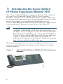
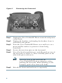
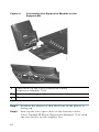
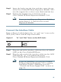
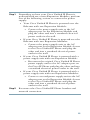
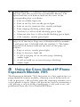
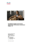
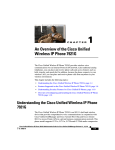
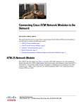
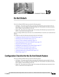
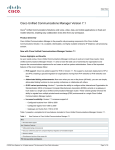
PHONE GUIDE
Cisco Unified IP Phone Expansion
Module 7915
INCLUDING LICENSE AND WARRANTY
1
Introducing the Cisco Unified IP Phone Expansion
Module 7915
2
Installing the Cisco Unified IP Phone
Expansion Module 7915
3
Features of the Cisco Unified IP Phone
Expansion Module 7915
4
Using the Cisco Unified IP Phone
Expansion Module 7915
5
Troubleshooting the Cisco Unified IP Phone
Expansion Module 7915
6
Technical Specifications for the Cisco Unified IP
Phone Expansion Module 7915
7
Where to Find More Information
8
Obtaining Documentation and Submitting a
Service Request
9
Cisco One-Year Limited Hardware Warranty Terms
1 Introducing the Cisco Unified
IP Phone Expansion Module 7915
The Cisco Unified IP Phone Expansion Module 7915 attaches
to your Cisco Unified IP Phone 7962G, Cisco Unified
IP Phone 7965G or Cisco Unified IP Phone 7975G, adding up
to 24 extra line appearances or programmable buttons to your
phone. Attaching a second Expansion Module to your
Cisco Unified IP Phone adds a total of 48 extra line appearances
or programmable buttons to your phone. See Figure 1.
Note
If you are running the SCCP protocol, you can
configure a maximum of 42 lines on your phone. For
example, if you configure two 24-line Cisco Unified IP
Phone Expansion Modules on a Cisco Unified IP Phone
7962G or Cisco Unified IP Phone 7965G, you will have
a total of 54 lines (48 lines from the modules in
addition to the 6 lines on the phone). However, only the
first 42 lines will be available for use.
The programmable buttons can be configured as phone line
buttons, speed-dial buttons, phone service buttons or phone
feature buttons.
Cisco Unified IP Phone 7962G with Two Expansion
Modules
187195
Figure 1
2
Before You Begin
Before you begin installing your Cisco Unified IP Phone
Expansion Module 7915, read each of these sections:
• Package Contents, page 3
• Footstand Kits, page 3
• Additional Equipment, page 4
• Safety Information, page 4
Package Contents
Verify that your package contents includes the following items:
• One Cisco Unified IP Phone Expansion Module 7915
• One interface cable
Footstand Kits
In addition to the package contents, you also need a Footstand
Kit (separate orderable item). If you are attaching one
Cisco Unified IP Phone Expansion Module 7915, you need the
single Footstand Kit. If you are attaching two Expansion
Module 7915s, you need the double Footstand Kit. The
Footstand Kit contains:
• One support bar (single with one thumbscrew, or double
with two thumbscrews)
• One footstand
3
Additional Equipment
You also need the following equipment.
• Small flat head screwdriver—for use during the installation
• Power supply unit—depending on how many
Expansion Modules you are installing and how your
Cisco Unified IP Phone is powered, you will require power
supply unit(s) as follows:
Power over the Ethernet to
your Cisco Unified IP Phone
With one or two Expansion
Modules, you need a power
supply unit (separate
orderable item).
Power supply to your
Cisco Unified IP Phone
With one Expansion Module,
you do not need a power
supply unit.
With two Expansion
Modules, you need a power
supply unit (separate
orderable item).
Note
Use of a non-Cisco certified power supply unit might
not work and voids the Cisco Unified IP Phone
Expansion Module 7915 product warranty.
Safety Information
The following safety warnings are for the Expansion
Module 7915. Read these notices before you install or use the
Expansion Module 7915. For translated warnings, refer to the
Regulatory Compliance and Safety Information for the Cisco
Unified IP Phone 7900 Series.
4
Installing and Using Your Expansion Module 7915
Read the following safety notices before installing or using your
Expansion Module 7915:
Warning
IMPORTANT SAFETY INSTRUCTIONS
This warning symbol means danger. You are in a situation
that could cause bodily injury. Before you work on any
equipment, be aware of the hazards involved with electrical
circuitry and be familiar with standard practices for
preventing accidents. Use the statement number provided at
the end of each warning to locate its translation in the
translated safety warnings that accompanied this device.
SAVE THESE INSTRUCTIONS
Warning
Read the installation instructions before you
connect the system to its power source.
Warning
Ultimate disposal of this product should be
handled according to all national laws and
regulations.
Warning
Do not work on the system or connect or
disconnect cables during periods of lightning
activity.
Warning
To avoid electric shock, do not connect safety
extra low voltage (SELV) circuits to telephone
network voltage (TNV) circuits. LAN ports contain
SELV circuits, and WAN ports contain TNV
circuits. Some LAN and WAN ports use RJ-45
connectors. Use caution when connecting cables.
5
Using an External Power Supply
Read the following warnings before you use the Cisco certified
external power supply with the Expansion Module 7915:
Caution
Only use the specified Cisco-approved power
supply on this product.
Warning
This product relies on the building's installation
for short-circuit (over current) protection. Ensure
that a fuse or circuit breaker no larger than 120
VAC, 15A U.S. (240 VAC, 10A international) is used
on the phase conductors (all current-carrying
conductors).
Warning
The device is designed to work with TN power
systems.
Warning
The plug-socket combination must be accessible
at all times because it serves as the main
disconnecting device.
Warning
The power supply must be placed indoors.
2 Installing the Cisco Unified
IP Phone Expansion Module 7915
Note
6
To ensure a successful installation of the
Expansion Module 7915, make sure you have read the
entire “Before You Begin” section on page 3.
To install the Cisco Unified IP Phone Expansion Module 7915,
perform the following tasks.
1. Remove the Footstand from the Cisco Unified IP Phone.
2. Connect the Support Bar to the Cisco Unified IP Phone.
3. Connect the Expansion Module 7915 to the Support Bar.
4. Connect the Interface Cable.
5. Connect the Power Supply Unit.
6. Connect the Footstand.
7. Connect a Laptop Cable Lock (optional).
Refer to the detailed instructions and corresponding
illustrations that follow for each of these high-level tasks.
Caution
To ensure a successful installation, verify with your
system administrator that your phone is ready for
the Cisco Unified IP Phone Expansion
Module 7915 and that Cisco Unified
Communications Manager is installed and
configured for the Cisco Unified IP
Phone Expansion Module 7915. Make sure that
you have all of the parts that you need (see the
“Before You Begin” section on page 3).
Remove the Footstand from the Cisco Unified
IP Phone
Refer to Figure 2 and the steps that follow.
7
Removing the Footstand
63147
Figure 2
Step 1
Unplug the Cisco Unified IP Phone network and power
connections.
Step 2
Unplug the handset, and unplug the headset if one is
attached to the phone.
Step 3
Turn the Cisco Unified IP Phone over and lay it on a
protected flat surface to prevent it from being
scratched.
Step 4
Locate the two foot pins on the footstand.
Step 5
Use a flat head screwdriver to carefully push on one of
the foot pins to release it. Then carefully push on the
other foot pin to release it.
Note
Step 6
8
You may have to lift and hold the
Cisco Unified IP Phone to support it when
pushing the foot pins. When pushing on the
footpins, push away from your body.
Lift off the footstand and store it separately.
Connect the Support Bar to the Cisco Unified
IP Phone
Refer to Figure 3 and the steps that follow.
Connecting the Support Bar
140969
140969
Figure 3
Step 1
Position the support bar on the back of the
Cisco Unified IP Phone so that it fits flush with the
phone.
Step 2
Locate the two connector pins.
Step 3
Use a flat head screwdriver to carefully push each of the
connector pins so that the support bar is firmly fastened
to the Cisco Unified IP Phone.
Connect the Expansion Module 7915 to the
Support Bar
Refer to Figure 4 and the steps that follow.
9
Figure 4
Connecting the Expansion Module to the
Support Bar
1
Open slots on the Cisco Unified IP Phone
Expansion Module 7915
2
Hooks on the support bar
3
Thumbscrews
Step 1
Position the phone so that the front of the phone is
facing up.
Step 2
Line up the two open slots on the bottom of the
Cisco Unified IP Phone Expansion Module 7915 with
the two hooks on the support bar.
10
Step 3
Insert the hooks into the slots and then rotate the top
of the Cisco Unified IP Phone Expansion Module 7915
into the support bar so that it rests flush with the bar.
Step 4
Tighten the thumbscrew on the back of the
Cisco Unified IP Phone Expansion Module 7915.
Note
If you are installing two Expansion Modules,
repeat Steps 2, 3, and 4 for the second
Expansion Module.
Connect the Interface Cable
Refer to Figure 5 which depicts the “in” and “out” icons on the
AUX jacks, and to and the steps that follow.
Figure 5
“In” and “Out” Icons on the AUX Jacks
In icon
Out icon
Step 1
Plug one end of the interface cable into the jack labeled
AUX on the Cisco Unified IP Phone.
Step 2
Plug the other end of the interface cable into the AUX
jack with the “in” icon underneath on the
Cisco Unified IP Phone Expansion Module 7915.
Note
If you are installing a second Cisco Unified
IP Phone Expansion Module 7915, continue
with Steps 3 and 4. Otherwise go to the
“Connect the Power Supply Unit” section on
page 12.
11
Step 3
Plug one end of the second interface cable into the AUX
jack with the “out” icon underneath on the first
Expansion Module (the one closest to the phone).
Step 4
Plug the other end of the second interface cable into the
AUX jack with the “in” icon underneath on the second
Expansion Module (the one next to the first Expansion
Module).
Connect the Power Supply Unit
Refer to Figure 6 and the steps that follow.
Figure 6
1
12
Connecting the Power Supply Unit
Power supply connector on the back of the
Expansion Module
Step 1
Depending on how your Cisco Unified IP Phone is
powered with one or two Expansion Modules, perform
one of the following actions to connect the power
supply:
• Your Cisco Unified IP Phone is powered over the
Ethernet with one Expansion Module:
– Connect the power supply unit to the AC
adapter port on the Expansion Module and
plug the other end into a standard electrical
power outlet in the wall.
• If your Cisco Unified IP Phone is powered over the
Ethernet with two Expansion Modules:
– Connect the power supply unit to the AC
adapter port on the Expansion Module closest
to the Cisco Unified IP Phone and plug the
other end into a standard electrical power
outlet in the wall.
• If your Cisco Unified IP Phone is powered with a
power supply unit with one Expansion Module:
– Reconnect the original Cisco Unified IP Phone
power supply unit to the AC adapter port on
the Cisco IP Phone and plug the other end into
a standard electrical power outlet in the wall.
• If your Cisco Unified IP Phone is powered with a
power supply unit with two Expansion Modules:
– Connect a second power supply unit to the AC
adapter port on the Expansion Module closest
to the Cisco Unified IP Phone and plug the
other end into a standard electrical power
outlet in the wall.
Step 2
Reconnect the Cisco Unified IP Phone handset and
network connection.
13
Connect the Footstand
Step 1
Locate the three hooks on the footstand.
Step 2
Position the hooks so that they align with the open slots
on the support bar.
Note
Step 3
There are four positions in each of the three
sets of open slots on the support bar. This lets
you choose the angle of the footstand.
Insert the footstand hooks into the support bar and
push in slightly to make the connection.
Connect a Laptop Cable Lock (optional)
Note
Supported only on phones that have a security slot on
the back of the phone. Contact your system
administrator for more information.
Refer to Figure 7 and the steps that follow.
14
Connecting a Laptop Cable Lock
140967
140967
Figure 7
Step 1
Detach the cable lock door from the support bar.
Step 2
Secure the security cable to a desktop.
Step 3
Insert the laptop cable lock into the security slot on the
back of the phone, lock it, and remove the key.
Start Up Sequence
After the Cisco Unified IP Phone Expansion Module 7915 is
installed, upon startup the buttons all show a steady amber
light. The Cisco logo, load name, segment name, and download
percentage are displayed. After the firmware is installed, the
LCD screen refreshes and the buttons all go off and any line
appearances are displayed in the LCD screen. You can then start
using the Expansion Module.
15
3 Features of the Cisco Unified IP
Phone Expansion Module 7915
The Cisco Unified IP Phone Expansion Module 7915 includes
the following features.
2
187193
1
1
16
Phone screen—Displays the phone number, speed dial
number (or name or other text label), phone service,
phone feature or Privacy assigned to each button. Icons
indicating line status appear similar to, and function the
same as, those on the Cisco Unified IP Phone to which it
is attached.
2
Lighted Buttons—12 buttons. Each button corresponds to
one line (just like on the Cisco Unified IP Phone). The
lights beneath each button indicate the state of the
corresponding line as follows:
• Line available: light off
• Line in use by you: steady green light
• Line in use by someone else: steady red light
• Line ringing: flashing amber light
• You have a call on hold: flashing green light
• Someone else has a call on hold: flashing green light
• Call transfer: steady green light
3
Shift Buttons—2 buttons. Each button corresponds to one
page of 12 line keys. Page one is labeled with the number
1 and page two is labeled with the number 2. The lights
beneath each button indicate the state of the page as
follows:
• Page is active: steady green light
• Page is inactive: light off
• A call is ringing on an inactive page: flashing
amber light
• A call on hold on an inactive page: flashing
amber light
4 Using the Cisco Unified IP Phone
Expansion Module 7915
The Expansion Module 7915 functions as a line appearance or
programmable button module, allowing you to keep track of
calls in progress, calls on hold, and calls requiring transfer, or to
access phone services. Most call functions, such as answering a
call, placing a call on hold, transferring a call, and so on, are
performed from the Cisco Unified IP Phone.
17
Note
If the Expansion Module 7915 buttons are configured
as phone features, they can be performed from the
Expansion Module.
Refer to the phone guide for your Cisco Unified IP Phone for
instructions about using your phone.
The following is a typical scenario when using the Cisco Unified
IP Phone and Cisco Unified IP Phone Expansion Module 7915
combination.
You receive a call for your Director at extension 12345. You
look at your Cisco Unified IP Phone Expansion Module 7915
and see that your Director has a call in progress with another
party and also has another call on hold. Looking down the
Cisco Unified IP Phone Expansion Module 7915 screen, you
note that another manager in your group has just completed a
call and could possibly assist the incoming caller. You consult
briefly with the incoming caller and then transfer the call to the
manager.
Keeping Your Call Information Private
If Privacy is programmed for one of your buttons, you can keep
your call information private from users who share your lines.
If you see a button labeled “Privacy,” then this feature has been
enabled for you by your system administrator. You toggle
privacy on and off by pressing the Privacy button when
receiving an incoming call. In addition, with Privacy enabled,
other shared lines are blocked from joining your calls.
Refer to the phone guide for your Cisco Unified IP Phone for
more information.
18
Configuring the Buttons on Your Cisco
Unified IP Phone Expansion Module 7915
Similar to your Cisco Unified IP Phone, you can configure speed
dial numbers or program buttons to access phone services on
the Cisco Unified IP Phone Expansion Module 7915. Before
you can do this, ask your system administrator for the following
information to access your Cisco Unified Communications
Manager User Options web page:
• The URL
• Your user name and password
After you have this information, you can configure your speed
dial numbers or program buttons to access phone services.
Phone services can include, for example, weather, stock quotes,
or corporate calendars and directories.
Refer to the phone guide for your Cisco Unified IP Phone for
more information.
Adjusting the Contrast
Similar to your Cisco Unified IP Phone, you can adjust the
contrast on the Cisco Unified IP Phone Expansion
Module 7915. Refer to the phone guide for your Cisco Unified
IP Phone for more information.
5 Troubleshooting the Cisco Unified
IP Phone Expansion Module 7915
The following table might help you if you are having difficulty
using your Cisco Unified IP Phone Expansion Module 7915.
Problem
No display on the
Cisco Unified IP Phone
Expansion Module 7915.
Solution
• Verify that all of the cable
connections are correct.
• Verify that you have power to
the Cisco Unified IP Phone
Expansion Module 7915(s).
19
Problem
Buttons on the first
Cisco Unified IP Phone
Expansion Module 7915
are all amber.
Solution
• Verify that the interface cable
between your Cisco Unified IP
Phone and your Cisco Unified
IP Phone Expansion
Module 7915 is connected.
• Verify with your system
administrator that your
Cisco Unified IP Phone
Expansion Module 7915 is
defined in Cisco Unified
Communications Manager.
Buttons on the second
Cisco Unified IP Phone
Expansion Module 7915
are all amber.
Verify with your system
administrator that your
Cisco Unified IP Phone
Expansion Module 7915 is
defined in Cisco Unified
Communications Manager.
Buttons are off, and the
Cisco logo is frozen in the
display area.
Verify with your system
administrator that your
Cisco Unified IP Phone
Expansion Module 7915 is
defined as a Cisco Unified
IP Phone Expansion Module 7915
in Cisco Unified Communications
Manager.
The page shift button does Verify with your system
not display the second
administrator that your
page.
Cisco Unified IP Phone
Expansion Module 7915 is
configured as a 24-line module
instead of a 12-line module.
in Cisco Unified Communications
Manager.
If you are experiencing other difficulties, contact your system
administrator.
20
6 Technical Specifications for the
Cisco Unified IP Phone Expansion
Module 7915
This section provides the physical and operating environment
specifications for the Cisco Unified IP Phone Expansion
Module 7915, as well as the regulatory compliance information.
Physical and Operating Environment
Specifications
Specification
Value or Range
Operating Temperature
32 to 104°F (0 to 40°C)
Operating relative humidity
10 to 95% (noncondensing)
Storage temperature
14 to 140°F (-10 to 60°C )
Height
203 mm, 8.0 in.
Width
121 mm, 4.75 in.
Depth
51 mm, 2.0 in.
Weight
366 g, 0.82 lb.
Power
48 VDC, 40mA max
Cable Specifications
The following are the cable specifications for the cables used
with the Cisco Unified IP Phone Expansion Module 7915:
• 2 RJ-11 jacks with 6-pin connectors for the interface cable
connections
• 48-V power connector. The diameter of the center pin in the
Expansion Module power jack (Switchcraft 712A) is 0.1 in.
(2.5 mm). The center pin is positive (+) voltage. The
miniature power plug required to mate with the power jack
on the Expansion Module is a Switchcraft 760 or
equivalent.
21
7 Where to Find More Information
The following sections provide sources for obtaining additional
documentation from Cisco Systems.
Related Documentation
The following documents provide additional information.
• Administration guide for your Cisco Unified IP
Phone—Provides instructions for the system
administrator about configuring the Cisco Unified
IP Phone Expansion Module 7915 in Cisco Unified
Communications Manager.
http://www.cisco.com/en/US/products/hw/phones/ps379/pr
od_maintenance_guides_list.html
• Phone guide for your Cisco Unified IP Phone—Provides
instructions for using the Cisco Unified IP Phone.
http://www.cisco.com/en/US/products/hw/phones/ps379/pr
oducts_user_guide_list.html
• Cisco Unified Communications Manager
documentation—Provides instructions for using the
Cisco Unified Communications Manager Administration
application to configure Cisco Unified IP Phones and
services.
http://www.cisco.com/en/US/products/sw/voicesw/ps556/pr
od_maintenance_guides_list.html
8 Obtaining Documentation and
Submitting a Service Request
For information on obtaining documentation, submitting a
service request, and gathering additional information, see the
monthly What’s New in Cisco Product Documentation, which
also lists all new and revised Cisco technical documentation, at:
http://www.cisco.com/en/US/docs/general/whatsnew/whatsnew.
html
22
Subscribe to the What’s New in Cisco Product Documentation as
a Really Simple Syndication (RSS) feed and set content to be
delivered directly to your desktop using a reader application. The
RSS feeds are a free service and Cisco currently supports RSS
version 2.0.
9 Cisco One-Year Limited Hardware
Warranty Terms
There are special terms applicable to your hardware warranty
and various services that you can use during the warranty
period. Your formal Warranty Statement, including the
warranties and license agreements applicable to Cisco software,
is available on Cisco.com. Follow these steps to access and
download the Cisco Information Packet and your warranty and
license agreements from Cisco.com.
1. Launch your browser, and go to this URL:
http://www.cisco.com/univercd/cc/td/doc/es_inpck/cetrans.
htm
The Warranties and License Agreements page appears.
2. To read the Cisco Information Packet, follow these steps:
a. Click the Information Packet Number field, and make
sure that the part number 78-5235-03A0 is highlighted.
b. Select the language in which you would like to read the
document.
c. Click Go.
The Cisco Limited Warranty and Software License page
from the Information Packet appears.
d. Read the document online, or click the PDF icon to
download and print the document in Adobe Portable
Document Format (PDF).
Note
You must have Adobe Acrobat Reader to view
and print PDF files. You can download the
reader from Adobe’s website:
http://www.adobe.com
23
3. To read translated and localized warranty information
about your product, follow these steps:
a. Enter this part number in the Warranty Document
Number field:
78-10747-01C0
b. Select the language in which you would like to view the
document.
c. Click Go.
The Cisco warranty page appears.
d. Read the document online, or click the PDF icon to
download and print the document in Adobe Portable
Document Format (PDF).
You can also contact the Cisco service and support website for
assistance:
http://www.cisco.com/public/Support_root.shtml.
Duration of Hardware Warranty
One (1) Year
Replacement, Repair, or Refund Policy for
Hardware
Cisco or its service center will use commercially reasonable
efforts to ship a replacement part within ten (10) working days
after receipt of a Return Materials Authorization (RMA)
request. Actual delivery times can vary, depending on the
customer location.
Cisco reserves the right to refund the purchase price as its
exclusive warranty remedy.
To Receive a Return Materials Authorization (RMA)
Number
Contact the company from whom you purchased the product. If
you purchased the product directly from Cisco, contact your
Cisco Sales and Service Representative.
Complete the information below, and keep it for reference.
Company product purchased from
Company telephone number
24
Product model number
Product serial number
Maintenance contract number
25
Americas Headquarters
Cisco Systems, Inc.
San Jose, CA
Asia Pacific Headquarters
Cisco Systems (USA) Pte. Ltd.
Singapore
Europe Headquarters
Cisco Systems International BV
Amsterdam, The Netherlands
Cisco has more than 200 offices worldwide. Addresses, phone numbers, and fax numbers are
listed on the Cisco Website at www.cisco.com/go/offices.
CCDE, CCENT, Cisco Eos, Cisco Lumin, Cisco StadiumVision, the Cisco logo, DCE, and Welcome to the Human
Network are trademarks; Changing the Way We Work, Live, Play, and Learn is a service mark; and Access Registrar,
Aironet, AsyncOS, Bringing the Meeting To You, Catalyst, CCDA, CCDP, CCIE, CCIP, CCNA, CCNP, CCSP, CCVP,
Cisco, the Cisco Certified Internetwork Expert logo, Cisco IOS, Cisco Press, Cisco Systems, Cisco Systems Capital, the
Cisco Systems logo, Cisco Unity, Collaboration Without Limitation, EtherFast, EtherSwitch, Event Center, Fast Step,
Follow Me Browsing, FormShare, GigaDrive, HomeLink, Internet Quotient, IOS, iPhone, iQ Expertise, the iQ logo, iQ
Net Readiness Scorecard, iQuick Study, IronPort, the IronPort logo, LightStream, Linksys, MediaTone, MeetingPlace,
MGX, Networkers, Networking Academy, Network Registrar, PCNow, PIX, PowerPanels, ProConnect, ScriptShare,
SenderBase, SMARTnet, Spectrum Expert, StackWise, The Fastest Way to Increase Your Internet Quotient, TransPath,
WebEx, and the WebEx logo are registered trademarks of Cisco Systems, Inc. and/or its affiliates in the United States and
certain other countries.
All other trademarks mentioned in this document or Website are the property of their respective owners. The use of the
word partner does not imply a partnership relationship between Cisco and any other company. (0804R)
© 2008 Cisco Systems, Inc. All rights reserved.
Printed in the USA on recycled paper containing 10% postconsumer waste.
OL-16220-01