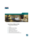
1
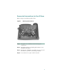
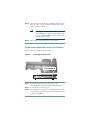
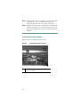
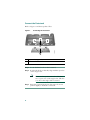
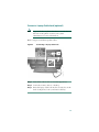
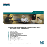
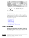
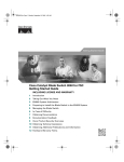
Phone Guide
Cisco IP Phone
Expansion Module 7914
INCLUDING LICENSE AND WARRANTY
1
Introducing the Cisco IP Phone Expansion
Module 7914
2
Installing the Expansion Module 7914
3
Features of the Expansion Module 7914
4
Using the Expansion Module 7914
5
Troubleshooting the Expansion Module 7914
6
Technical Specifications for the
Expansion Module 7914
7
Where to Find More Information
8
Cisco Product Security Overview
9
Obtaining Technical Assistance
10 Cisco One-Year Limited Hardware
Warranty Terms
1 Introducing the Cisco IP Phone
Expansion Module 7914
The Cisco IP Phone Expansion Module 7914 attaches to your
Cisco IP Phone, adding 14 extra line appearances or
programmable buttons to your phone. Attaching a second
Expansion Module to your Cisco IP Phone adds a total of 28
extra line appearances or programmable buttons to your phone.
The programmable buttons can be configured for speed dial
numbers or to access phone services.
Note
Cisco IP Phone 7960G with 2 Expansion Modules
120043
Figure 1
For the latest information about supported phone
models, contact your system administrator.
Before You Begin
Before you begin installing your Expansion Module 7914, read
each of these sections:
• Package Contents, page 3
• Footstand Kits, page 3
2
• Additional Equipment, page 3
• Safety Information, page 4
Package Contents
Make sure that your package includes the following items:
• One Cisco IP Phone Expansion Module 7914
• One interface cable
• This Cisco IP Phone Expansion Module 7914 Phone
Guide
Footstand Kits
In addition to the items in the package, you also need a
Footstand Kit (separate orderable item). If you are attaching
one Expansion Module 7914, you need the single Footstand
Kit. If you are attaching two Expansion Module 7914s, you
need the double Footstand Kit. The Footstand Kit contains:
• One support bar (single with one thumbscrew, or double
with two thumbscrews)
• One footstand
Additional Equipment
You also need the following equipment.
• Small flat head screwdriver—for use during the installation
• Power supply unit—depending on how many
Expansion Modules you are installing and how your
Cisco IP Phone is powered, you will require power supply
unit(s) as follows:
Power over the Ethernet to
your Cisco IP Phone
With one or two Expansion
Modules, you need a power
supply unit (separate
orderable item).
3
Power supply to your
Cisco IP Phone
With one Expansion Module,
you do not need a power
supply unit.
With two Expansion
Modules, you need a power
supply unit (separate
orderable item).
Note
Use of a non-Cisco certified power supply unit might
not work and voids the Expansion Module 7914
product warranty.
Safety Information
The following safety warnings are for the
Expansion Module 7914. Read these notices before you install
or use the Expansion Module 7914. For translated warnings,
refer to the Regulatory Compliance and Safety Information for
the Cisco IP Phone 7900 Series.
Installing and Using Your Expansion Module 7914
Read the following safety notices before installing or using your
Expansion Module 7914:
Warning
IMPORTANT SAFETY INSTRUCTIONS
This warning symbol means danger. You are in a situation
that could cause bodily injury. Before you work on any
equipment, be aware of the hazards involved with electrical
circuitry and be familiar with standard practices for
preventing accidents. Use the statement number provided at
the end of each warning to locate its translation in the
translated safety warnings that accompanied this device.
SAVE THESE INSTRUCTIONS
Warning
4
Read the installation instructions before you
connect the system to its power source.
Warning
Ultimate disposal of this product should be
handled according to all national laws and
regulations.
Warning
Do not work on the system or connect or
disconnect cables during periods of lightning
activity.
Warning
To avoid electric shock, do not connect safety
extra low voltage (SELV) circuits to telephone
network voltage (TNV) circuits. LAN ports contain
SELV circuits, and WAN ports contain TNV
circuits. Some LAN and WAN ports use RJ-45
connectors. Use caution when connecting cables.
Using an External Power Supply
The following warnings apply when you use the external power
supply with the Expansion Module 7914:
Warning
This product relies on the building's installation
for short-circuit (over current) protection. Ensure
that a fuse or circuit breaker no larger than 120
VAC, 15A U.S. (240 VAC, 10A international) is used
on the phase conductors (all current-carrying
conductors).
Warning
The device is designed to work with TN power
systems.
Warning
The plug-socket combination must be accessible
at all times because it serves as the main
disconnecting device.
5
Warning
The power supply must be placed indoors.
Caution
Only use the specified Cisco-approved power
supply on this product.
2 Installing the Expansion Module
7914
Note
To ensure a successful installation of the
Expansion Module 7914, make sure you have read the
entire “Before You Begin” section on page 2.
To install the Expansion Module 7914, perform the following
steps.
1. Remove the Footstand from the Cisco IP Phone.
2. Connect the Support Bar to the Cisco IP Phone.
3. Connect the Expansion Module 7914 to the Support Bar.
4. Connect the Interface Cable.
5. Connect the Power Supply.
6. Connect the Footstand.
7. Connect a Laptop Cable Lock (optional).
Refer to the detailed instructions and corresponding
illustrations that follow for each of these high-level steps.
Caution
6
To ensure a successful installation, verify with your
system administrator that your phone is ready for
the Expansion Module 7914 and that
Cisco CallManager is installed and configured for
the Expansion Module 7914. Make sure that you
have all of the parts that you need (see the “Before
You Begin” section on page 2).
Remove the Footstand from the Cisco IP Phone
Refer to Figure 2 and the steps that follow.
Removing the Footstand
63147
Figure 2
Step 1
Unplug the Cisco IP Phone network and power
connections.
Step 2
Unplug the handset, and unplug the headset if one is
attached to the phone.
Step 3
Turn the Cisco IP Phone over and lay it on a protected
flat surface to prevent it from being scratched.
Step 4
Locate the two foot pins on the footstand.
7
Step 5
Use a flat head screwdriver to carefully push on one of
the foot pins to release it. Then carefully push on the
other foot pin to release it.
Note
Step 6
You may have to lift and hold the
Cisco IP Phone to support it when pushing the
foot pins. When pushing on the footpins, push
away from your body.
Lift off the footstand and store it separately.
Connect the Support Bar to the Cisco IP Phone
Refer to Figure 3 and the steps that follow.
Connecting the Support Bar
140969
140969
Figure 3
Step 1
Position the support bar on the back of the
Cisco IP Phone so that it fits flush with the phone.
Step 2
Locate the two connector pins.
Step 3
Use a flat head screwdriver to carefully push each of the
connector pins so that the support bar is firmly fastened
to the Cisco IP Phone.
8
Connect the Expansion Module 7914 to the
Support Bar
Refer to Figure 4 and the steps that follow.
Figure 4
Connecting the Expansion Module
1
Open slots on the Expansion Module 7914
2
Hooks on the support bar
3
Thumbscrews
9
Step 1
Position the phone so that the front of the phone is
facing up.
Step 2
Line up the two open slots on the bottom of the
Expansion Module 7914 with the two hooks on the
support bar.
Step 3
Insert the hooks into the slots and then rotate the top
of the Expansion Module 7914 into the support bar so
that it rests flush with the bar.
Step 4
Tighten the thumbscrew on the back of the
Expansion Module 7914.
Note
If you are installing two Expansion Modules,
repeat Steps 2, 3, and 4 for the second
Expansion Module.
Connect the Interface Cable
Refer to the following table, which depicts the “in” and “out”
icons on the AUX jacks, and to Figure 5 and the steps that
follow.
In icon
Note
10
Out icon
On your Cisco IP Phone or Expansion Module 7914,
the AUX jack may be labelled RS-232. In this case read
“RS-232 jack” for AUX jack in Figure 5 and Steps 1 –
4 in this section.
140166
Connecting the Interface Cable
140966
Figure 5
2
4
3
1
1
Interface cable connection to the AUX jack on the
Cisco IP Phone
2
Interface cable connection to the AUX jack labeled with
the “in” icon on Expansion Module 1
3
Second interface cable connection to the AUX jack labeled
with the “out” icon on Expansion Module 1
4
Second interface cable connection to the AUX jack labeled
with the “in” icon on Expansion Module 2
Step 1
Plug one end of the interface cable into the jack labeled
AUX on the Cisco IP Phone.
Step 2
Plug the other end of the interface cable into the AUX
jack with the “in” icon underneath on the
Expansion Module 7914.
Note
If you are installing a second
Expansion Module 7914, continue with Steps
3 and 4. Otherwise go to the “Connect the
Power Supply” section on page 12.
11
Step 3
Plug one end of the second interface cable into the AUX
jack with the “out” icon underneath on the first
Expansion Module (the one closest to the phone).
Step 4
Plug the other end of the second interface cable into the
AUX jack with the “in” icon underneath on the second
Expansion Module (the one next to the first Expansion
Module).
Connect the Power Supply
Refer to Figure 6 and the steps that follow.
Figure 6
1
12
Connecting the Power Supply
Power supply connector on the back of the
Expansion Module
Step 1
Depending on how your Cisco IP Phone is powered
with one or two Expansion Modules, perform one of
the following actions to connect the power supply:
• Your Cisco IP Phone is powered over the Ethernet
with one Expansion Module:
– connect the power supply unit to the AC
adapter port on the Expansion Module and
plug the other end into a standard electrical
power outlet in the wall.
• If your Cisco IP Phone is powered over the
Ethernet with two Expansion Modules:
– connect the power supply unit to the AC
adapter port on the Expansion Module closest
to the Cisco IP Phone and plug the other end
into a standard electrical power outlet in the
wall.
• If your Cisco IP Phone is powered with a power
supply unit with one Expansion Module:
– reconnect the original Cisco IP Phone power
supply unit to the AC adapter port on the
Cisco IP Phone and plug the other end into a
standard electrical power outlet in the wall.
• If your Cisco IP Phone is powered with a power
supply unit with two Expansion Modules:
– connect a second power supply unit to the AC
adapter port on the Expansion Module closest
to the Cisco IP Phone and plug the other end
into a standard electrical power outlet in the
wall.
Step 2
Reconnect the Cisco IP Phone handset and network
connection.
13
Connect the Footstand
Refer to Figure 7 and the steps that follow.
Figure 7
Connecting the Footstand
2
1
Slots on the support bar
2
Hooks on the footstand
140968
1
Step 1
Locate the three hooks on the footstand.
Step 2
Position the hooks so that they align with the open slots
on the support bar.
Note
Step 3
14
There are four positions in each of the three
sets of open slots on the support bar. This lets
you choose the angle of the footstand.
Insert the footstand hooks into the support bar and
push in slightly to make the connection.
Connect a Laptop Cable Lock (optional)
Note
Supported only on phones that have a security slot on
the back of the phone. Contact your system
administrator for more information.
Refer to Figure 8 and the steps that follow.
Connecting a Laptop Cable Lock
140967
140967
Figure 8
Step 1
Detach the cable lock door from the support bar.
Step 2
Secure the security cable to a desktop.
Step 3
Insert the laptop cable lock into the security slot on the
back of the phone, lock it, and remove the key.
15
Start Up Sequence
After the Expansion Module 7914 is installed, upon startup the
buttons all show a steady red light. Then the LCD screen
refreshes and the buttons all go off and any line appearances are
displayed in the LCD screen. You can then start using the
Expansion Module.
3 Features of the
Expansion Module 7914
The Expansion Module 7914 includes the following features.
1
16
Phone screen—Displays the phone number, speed dial
number (or name or other text label), phone service, or
Privacy assigned to each button. Icons indicating line
status appear similar to, and function the same as, those
on the Cisco IP Phone to which it is attached.
2
Lighted Buttons—14 buttons. Each button corresponds to
one line (just like on the Cisco IP Phone). The lights
beneath each button indicate the state of the
corresponding line as follows:
Line available: light off
Line in use by you: steady green light
Line in use by someone else: steady red light
Line ringing: flashing amber light
You have a call on hold: flashing green light
Someone else has a call on hold: flashing red light
Call transfer: steady green light
4 Using the Expansion Module 7914
The Expansion Module 7914 functions as a line appearance or
programmable button module, allowing you to keep track of
calls in progress, calls on hold, and calls requiring transfer, or to
access phone services. All call functions, such as answering a
call, placing a call on hold, transferring a call, and so on, are
performed from the Cisco IP Phone. Refer to the phone guide
for your Cisco IP Phone for instructions about using your
phone.
Here is a typical scenario when using the Cisco IP Phone and
Expansion Module 7914 combination.
You receive a call for your Director at extension 12345. You
look at your Expansion Module 7914 and see that your
Director has a call in progress with another party and also has
another call on hold. Looking down the
Expansion Module 7914 screen, you note that another manager
in your group has just completed a call and could possibly assist
the incoming caller. You consult briefly with the incoming caller
and then transfer the call to the manager.
17
Keeping Your Call Information Private
If Privacy is programmed for one of your buttons, you can keep
your call information private from users who share your lines.
If you see a button labeled “Privacy,” then this feature has been
enabled for you by your system administrator. You toggle
privacy on and off by pressing the Privacy button when
receiving an incoming call. In addition, with Privacy enabled,
other shared lines are blocked from joining your calls. Refer to
the phone guide for your Cisco IP Phone for more information.
Configuring the Buttons on Your
Expansion Module 7914
Similar to your Cisco IP Phone, you can configure speed dial
numbers or program buttons to access phone services on the
Expansion Module 7914. Before you can do this, ask your
system administrator for the following information to access
your Cisco IP Phone User Options web page:
• the URL
• your user name and password
After you have this information, you can configure your speed
dial numbers or program buttons to access phone services.
Phone services can include, for example, weather, stock quotes,
or corporate calendars and directories.
Refer to the phone guide for your Cisco IP Phone for more
information.
Adjusting the Contrast
Similar to your Cisco IP Phone, you can adjust the contrast on
the Expansion Module 7914. Refer to the phone guide for your
Cisco IP Phone for more information.
18
5 Troubleshooting the
Expansion Module 7914
The following table might help you if you are having difficulty
using your Expansion Module 7914.
Problem
No display on the
Expansion Module 7914.
Solution
• Verify that all of the cable
connections are correct.
• Verify that you have power to
the
Expansion Module 7914(s).
Buttons on the first
Expansion Module 7914
are all red.
Verify with your system
administrator that your
Expansion Module 7914 is
defined in Cisco CallManager.
Buttons on the second
Expansion Module 7914
are all amber.
Verify with your system
administrator that your
Expansion Module 7914 is
defined in Cisco CallManager.
If you are experiencing other difficulties, contact your system
administrator.
6 Technical Specifications for the
Expansion Module 7914
This section provides the physical and operating environment
specifications for the Cisco IP Phone Expansion Module 7914,
as well as the regulatory compliance information.
19
Physical and Operating Environment
Specifications
Specification
Value or Range
Operating
Temperature
32 to 104°F (0 to 40°C)
Operating relative
humidity
10 to 95% (noncondensing)
Storage
temperature
14 to 140°F (-10 to 60°C )
Height
203 mm, 8.0 in.
Width
121 mm, 4.75 in.
Depth
51 mm, 2.0 in.
Weight
366 g, 0.82 lb.
Power
48 VDC, 40mA max
Cable Specifications
• 2 RJ-11 jacks with 6-pin connectors for the interface cable
connections
• 48-V power connector. The diameter of the center pin in the
Expansion Module power jack (Switchcraft 712A) is 0.1 in.
(2.5 mm). The center pin is positive (+) voltage. The
miniature power plug required to mate with the power jack
on the Expansion Module is a Switchcraft 760 or
equivalent.
20
7 Where to Find More Information
The following sections provide sources for obtaining additional
documentation from Cisco Systems.
Related Documentation
The following documents provide additional information.
• Cisco IP Phone Administration Guide for
Cisco CallManager—Provides instructions for the system
administrator about configuring the
Expansion Module 7914 in Cisco CallManager.
http://www.cisco.com/univercd/cc/td/doc/product/voice/
c_ipphon/index.htm
• Phone guide for your Cisco IP Phone—Provides
instructions for using the Cisco IP Phone.
http://www.cisco.com/univercd/cc/td/doc/product/voice/
c_ipphon/index.htm
• Cisco CallManager documentation—Provides instructions
for using the Cisco CallManager Administration
application to configure Cisco IP Phones and services.
http://www.cisco.com/univercd/cc/td/doc/product/voice/
c_callmg/index.htm
Obtaining Documentation
Cisco documentation and additional literature are available on
Cisco.com. Cisco also provides several ways to obtain technical
assistance and other technical resources. These sections explain
how to obtain technical information from Cisco Systems.
Cisco.com
You can access the most current Cisco documentation at
this URL:
http://www.cisco.com/techsupport
21
You can access the Cisco website at this URL:
http://www.cisco.com
You can access international Cisco websites at this URL:
http://www.cisco.com/public/countries_languages.shtml
Product Documentation DVD
Cisco documentation and additional literature are available in
the Product Documentation DVD package, which may have
shipped with your product. The Product Documentation DVD
is updated regularly and may be more current than printed
documentation.
The Product Documentation DVD is a comprehensive library of
technical product documentation on portable media. The DVD
enables you to access multiple versions of hardware and
software installation, configuration, and command guides for
Cisco products and to view technical documentation in HTML.
With the DVD, you have access to the same documentation that
is found on the Cisco website without being connected to the
Internet. Certain products also have .pdf versions of the
documentation available.
The Product Documentation DVD is available as a single unit or
as a subscription. Registered Cisco.com users (Cisco direct
customers) can order a Product Documentation DVD (product
number DOC-DOCDVD=) from Cisco Marketplace at this
URL:
http://www.cisco.com/go/marketplace/
Ordering Documentation
Beginning June 30, 2005, registered Cisco.com users may order
Cisco documentation at the Product Documentation Store in the
Cisco Marketplace at this URL:
http://www.cisco.com/go/marketplace/
Nonregistered Cisco.com users can order technical documentation
from 8:00 a.m. to 5:00 p.m. (0800 to 1700) PDT by calling 1 866
463-3487 in the United States and Canada, or elsewhere by calling
011 408 519-5055. You can also order documentation by e-mail at
22
[email protected] or by fax at
1 408 519-5001 in the United States and Canada, or elsewhere at
011 408 519-5001.
Documentation Feedback
You can rate and provide feedback about Cisco technical
documents by completing the online feedback form that appears
with the technical documents on Cisco.com.
You can send comments about Cisco documentation to
[email protected].
You can submit comments by using the response card (if
present) behind the front cover of your document or by writing
to the following address:
Cisco Systems
Attn: Customer Document Ordering
170 West Tasman Drive
San Jose, CA 95134-9883
We appreciate your comments.
Obtaining Additional Publications and
Information
Information about Cisco products, technologies, and network
solutions is available from various online and printed sources.
• Cisco Marketplace provides a variety of Cisco books,
reference guides, documentation, and logo merchandise.
Visit Cisco Marketplace, the company store, at this URL:
http://www.cisco.com/go/marketplace/
• Cisco Press publishes a wide range of general networking,
training and certification titles. Both new and experienced
users will benefit from these publications. For current Cisco
Press titles and other information, go to Cisco Press at
this URL:
http://www.ciscopress.com
23
• Packet magazine is the Cisco Systems technical user
magazine for maximizing Internet and networking
investments. Each quarter, Packet delivers coverage of the
latest industry trends, technology breakthroughs, and Cisco
products and solutions, as well as network deployment and
troubleshooting tips, configuration examples, customer
case studies, certification and training information, and
links to scores of in-depth online resources. You can access
Packet magazine at this URL:
http://www.cisco.com/packet
• iQ Magazine is the quarterly publication from Cisco
Systems designed to help growing companies learn how
they can use technology to increase revenue, streamline
their business, and expand services. The publication
identifies the challenges facing these companies and the
technologies to help solve them, using real-world case
studies and business strategies to help readers make sound
technology investment decisions. You can access iQ
Magazine at this URL:
http://www.cisco.com/go/iqmagazine
or view the digital edition at this URL:
http://ciscoiq.texterity.com/ciscoiq/sample/
• Internet Protocol Journal is a quarterly journal published
by Cisco Systems for engineering professionals involved in
designing, developing, and operating public and private
internets and intranets. You can access the Internet Protocol
Journal at this URL:
http://www.cisco.com/ipj
• Networking products offered by Cisco Systems, as well as
customer support services, can be obtained at this URL:
http://www.cisco.com/en/US/products/index.html
24
• Networking Professionals Connection is an interactive
website for networking professionals to share questions,
suggestions, and information about networking products
and technologies with Cisco experts and other networking
professionals. Join a discussion at this URL:
http://www.cisco.com/discuss/networking
• World-class networking training is available from Cisco.
You can view current offerings at this URL:
http://www.cisco.com/en/US/learning/index.html
8 Cisco Product Security Overview
Cisco provides a free online Security Vulnerability Policy portal
at this URL:
http://www.cisco.com/en/US/products/products_security_vulne
rability_policy.html
From this site, you can perform these tasks:
• Report security vulnerabilities in Cisco products.
• Obtain assistance with security incidents that involve Cisco
products.
• Register to receive security information from Cisco.
A current list of security advisories and notices for Cisco
products is available at this URL:
http://www.cisco.com/go/psirt
If you prefer to see advisories and notices as they are updated in
real time, you can access a Product Security Incident Response
Team Really Simple Syndication (PSIRT RSS) feed from
this URL:
http://www.cisco.com/en/US/products/products_psirt_rss_feed.
html
25
Reporting Security Problems in Cisco Products
Cisco is committed to delivering secure products. We test our
products internally before we release them, and we strive to
correct all vulnerabilities quickly. If you think that you might
have identified a vulnerability in a Cisco product, contact
PSIRT:
• Emergencies — [email protected]
An emergency is either a condition in which a system is
under active attack or a condition for which a severe and
urgent security vulnerability should be reported. All other
conditions are considered nonemergencies.
• Nonemergencies — [email protected]
In an emergency, you can also reach PSIRT by telephone:
• 1 877 228-7302
• 1 408 525-6532
Tip
We encourage you to use Pretty Good Privacy (PGP) or
a compatible product to encrypt any sensitive
information that you send to Cisco. PSIRT can work
from encrypted information that is compatible with
PGP versions 2.x through 8.x.
Never use a revoked or an expired encryption key. The
correct public key to use in your correspondence with
PSIRT is the one linked in the Contact Summary section
of the Security Vulnerability Policy page at this URL:
http://www.cisco.com/en/US/products/products_securi
ty_vulnerability_policy.html
The link on this page has the current PGP key ID in use.
9 Obtaining Technical Assistance
Cisco Technical Support provides 24-hour-a-day
award-winning technical assistance. The Cisco Technical
Support & Documentation website on Cisco.com features
extensive online support resources. In addition, if you have a
26
valid Cisco service contract, Cisco Technical Assistance Center
(TAC) engineers provide telephone support. If you do not have
a valid Cisco service contract, contact your reseller.
Cisco Technical Support & Documentation
Website
The Cisco Technical Support & Documentation website
provides online documents and tools for troubleshooting and
resolving technical issues with Cisco products and technologies.
The website is available 24 hours a day, at this URL:
http://www.cisco.com/techsupport
Access to all tools on the Cisco Technical Support &
Documentation website requires a Cisco.com user ID and
password. If you have a valid service contract but do not have a
user ID or password, you can register at this URL:
http://tools.cisco.com/RPF/register/register.do
Note
Use the Cisco Product Identification (CPI) tool to
locate your product serial number before submitting a
web or phone request for service. You can access the
CPI tool from the Cisco Technical Support &
Documentation website by clicking the Tools &
Resources link under Documentation & Tools. Choose
Cisco Product Identification Tool from the
Alphabetical Index drop-down list, or click the Cisco
Product Identification Tool link under Alerts & RMAs.
The CPI tool offers three search options: by product ID
or model name; by tree view; or for certain products, by
copying and pasting show command output. Search
results show an illustration of your product with the
serial number label location highlighted. Locate the
serial number label on your product and record the
information before placing a service call.
27
Submitting a Service Request
Using the online TAC Service Request Tool is the fastest way to
open S3 and S4 service requests. (S3 and S4 service requests are
those in which your network is minimally impaired or for which
you require product information.) After you describe your
situation, the TAC Service Request Tool provides recommended
solutions. If your issue is not resolved using the recommended
resources, your service request is assigned to a Cisco TAC
engineer. The TAC Service Request Tool is located at this URL:
http://www.cisco.com/techsupport/servicerequest
For S1 or S2 service requests or if you do not have Internet
access, contact the Cisco TAC by telephone. (S1 or S2 service
requests are those in which your production network is down or
severely degraded.) Cisco TAC engineers are assigned
immediately to S1 and S2 service requests to help keep your
business operations running smoothly.
To open a service request by telephone, use one of the following
numbers:
Asia-Pacific: +61 2 8446 7411 (Australia: 1 800 805 227)
EMEA: +32 2 704 55 55
USA: 1 800 553-2447
For a complete list of Cisco TAC contacts, go to this URL:
http://www.cisco.com/techsupport/contacts
Definitions of Service Request Severity
To ensure that all service requests are reported in a standard
format, Cisco has established severity definitions.
Severity 1 (S1)—Your network is “down,” or there is a critical
impact to your business operations. You and Cisco will commit
all necessary resources around the clock to resolve the situation.
Severity 2 (S2)—Operation of an existing network is severely
degraded, or significant aspects of your business operation are
negatively affected by inadequate performance of Cisco
products. You and Cisco will commit full-time resources during
normal business hours to resolve the situation.
28
Severity 3 (S3)—Operational performance of your network is
impaired, but most business operations remain functional. You
and Cisco will commit resources during normal business hours
to restore service to satisfactory levels.
Severity 4 (S4)—You require information or assistance with
Cisco product capabilities, installation, or configuration. There
is little or no effect on your business operations.
10 Cisco One-Year Limited
Hardware Warranty Terms
There are special terms applicable to your hardware warranty
and various services that you can use during the warranty
period. Your formal Warranty Statement, including the
warranties and license agreements applicable to Cisco software,
is available on Cisco.com. Follow these steps to access and
download the Cisco Information Packet and your warranty and
license agreements from Cisco.com.
1. Launch your browser, and go to this URL:
http://www.cisco.com/univercd/cc/td/doc/es_inpck/cetrans.
htm
The Warranties and License Agreements page appears.
2. To read the Cisco Information Packet, follow these steps:
a. Click the Information Packet Number field, and make
sure that the part number 78-5235-03A0 is highlighted.
b. Select the language in which you would like to read the
document.
c. Click Go.
The Cisco Limited Warranty and Software License page
from the Information Packet appears.
d. Read the document online, or click the PDF icon to
download and print the document in Adobe Portable
Document Format (PDF).
29
Note
You must have Adobe Acrobat Reader to view
and print PDF files. You can download the
reader from Adobe’s website:
http://www.adobe.com
3. To read translated and localized warranty information
about your product, follow these steps:
a. Enter this part number in the Warranty Document
Number field:
78-10747-01C0
b. Select the language in which you would like to view the
document.
c. Click Go.
The Cisco warranty page appears.
d. Read the document online, or click the PDF icon to
download and print the document in Adobe Portable
Document Format (PDF).
You can also contact the Cisco service and support website for
assistance:
http://www.cisco.com/public/Support_root.shtml.
Duration of Hardware Warranty
One (1) Year
Replacement, Repair, or Refund Policy for
Hardware
Cisco or its service center will use commercially reasonable
efforts to ship a replacement part within ten (10) working days
after receipt of a Return Materials Authorization (RMA)
request. Actual delivery times can vary, depending on the
customer location.
Cisco reserves the right to refund the purchase price as its
exclusive warranty remedy.
30
To Receive a Return Materials Authorization (RMA)
Number
Contact the company from whom you purchased the product. If
you purchased the product directly from Cisco, contact your
Cisco Sales and Service Representative.
Complete the information below, and keep it for reference.
Company product purchased from
Company telephone number
Product model number
Product serial number
Maintenance contract number
31
Corporate Headquarters
Cisco Systems, Inc.
170 West Tasman Drive
San Jose, CA 95134-1706
USA
www.cisco.com
Tel: 408 526-4000
800 553-NETS (6387)
Fax: 408 526-4100
European Headquarters
Cisco Systems International BV
Haarlerbergpark
Haarlerbergweg 13-19
1101 CH Amsterdam
The Netherlands
www-europe.cisco.com
Tel: 31 0 20 357 1000
Fax: 31 0 20 357 1100
Americas Headquarters
Cisco Systems, Inc.
170 West Tasman Drive
San Jose, CA 95134-1706
USA
www.cisco.com
Tel: 408 526-7660
Fax: 408 527-0883
Asia Pacific Headquarters
Cisco Systems, Inc.
168 Robinson Road
#28-01 Capital Tower
Singapore 068912
www.cisco.com
Tel: +65 6317 7777
Fax: +65 6317 7799
Cisco Systems has more than 200 offices in the following countries. Addresses, phone numbers, and
fax numbers are listed on the
Cisco Website at www.cisco.com/go/offices
Argentina • Australia • Austria • Belgium • Brazil • Bulgaria • Canada • Chile • China PRC • Colombia • Costa Rica
Croatia • Cyprus • Czech Republic • Denmark • Dubai, UAE • Finland • France • Germany • Greece
Hong Kong SAR • Hungary • India • Indonesia • Ireland • Israel • Italy • Japan • Korea • Luxembourg
Malaysia • Mexico • The Netherlands • New Zealand • Norway • Peru • Philippines • Poland • Portugal • Puerto
Rico • Romania • Russia • Saudi Arabia • cotland • Singapore • Slovakia • Slovenia • South Africa • Spain • Sweden
Switzerland • Taiwan • Thailand • Turkey • Ukraine • United Kingdom • United States • Venezuela • Vietnam • Zimbabwe
CCSP, CCVP, the Cisco Square Bridge logo, Follow Me Browsing, and StackWise are trademarks of Cisco
Systems, Inc.; Changing the Way We Work, Live, Play, and Learn, and iQuick Study are service marks of
Cisco Systems, Inc.; and Access Registrar, Aironet, ASIST, BPX, Catalyst, CCDA, CCDP, CCIE, CCIP,
CCNA, CCNP, Cisco, the Cisco Certified Internetwork Expert logo, Cisco IOS, Cisco Press, Cisco Systems,
Cisco Systems Capital, the Cisco Systems logo, Cisco Unity, Empowering the Internet Generation,
Enterprise/Solver, EtherChannel, EtherFast, EtherSwitch, Fast Step, FormShare, GigaDrive, GigaStack,
HomeLink, Internet Quotient, IOS, IP/TV, iQ Expertise, the iQ logo, iQ Net Readiness Scorecard,
LightStream, Linksys, MeetingPlace, MGX, the Networkers logo, Networking Academy, Network
Registrar, Packet, PIX, Post-Routing, Pre-Routing, ProConnect, RateMUX, ScriptShare, SlideCast,
SMARTnet, StrataView Plus, TeleRouter, The Fastest Way to Increase Your Internet Quotient, and
TransPath are registered trademarks of Cisco Systems, Inc. and/or its affiliates in the United States and
certain other countries.
All other trademarks mentioned in this document or Website are the property of their respective owners.
The use of the word partner does not imply a partnership relationship between Cisco and any other
company. (0502R)
© 2005 Cisco Systems, Inc. All rights reserved.
Printed in Malaysia
78-13014-07