1
C H A P T E R
3
Initial Configuration
This chapter describes how to configure the Cisco ONS 15530 so it can be accessed by other devices.
•
About the CPU Switch Module, page 3-1
•
Starting Up the Cisco ONS 15530, page 3-2
•
Using the Console Ports, NME Ports, and Auxiliary Ports, page 3-2
•
About Passwords, page 3-3
•
Configuring IP Access on the NME Interface, page 3-4
•
Configuring the Host Name, page 3-6
•
About NTP, page 3-7
•
Configuring NTP, page 3-8
•
Configuring Security Features, page 3-9
•
About CPU Switch Module Redundancy, page 3-12
•
Configuring CPU Switch Module Redundancy, page 3-15
•
About the Software Configuration Register, page 3-25
•
Changing the Software Configuration Register, page 3-29
•
About Fan Failure Shutdown, page 3-30
•
Configuring Fan Failure Shutdown, page 3-30
About the CPU Switch Module
The CPU switch module provides intelligence to the Cisco ONS 15530. The CPU switch module
supports SNMP (Simple Network Management Protocol) and many MIBs (Management Information
Bases).
The Cisco ONS 15530 uses a QED RM7000 RISC processor. It runs at 78 MHz externally and at 234
MHz internally. It has a 64-bit multiplexed address and data bus with byte parity running at 78 MHz. It
has separate internal L1 instruction and data caches of 16 KB each and internal L2 combined
instruction/data cache of 256 KB.
The CPU switch modules also contains a 32 by 32 switch fabric that directs traffic from client cards to
trunk cards. The switch fabric supports 2.5 Gbps data signals with 2R transparency.
Cisco ONS 15530 Configuration Guide and Command Reference
78-16019-02, Cisco IOS Release 12.2(18)SV2
3-1
Chapter 3
Initial Configuration
Starting Up the Cisco ONS 15530
The CPU switch module provides a slot on the front panel that accommodates a CompactFlash card. You
can use the CompactFlash card for system image upgrades, FPGA image upgrades, statistics gathering,
and other file system applications.
The Cisco ONS 15530 supports redundant operation with dual CPU switch modules. The CPU switch
modules reside in slots 5 and 6, the sixth and seventh slots from the left as you face the chassis. For more
information about redundancy, see the “About CPU Switch Module Redundancy” section on page 3-12.
For more information on the CPU switch module, refer to the Cisco ONS 15530 ESP Hardware
Installation Guide.
Starting Up the Cisco ONS 15530
Before starting up the Cisco ONS 15530, you should verify the following:
•
The system is set for the correct AC (or DC) power voltages.
Refer to the Cisco ONS 15530 Hardware Installation Guide for correct power voltages.
•
The cables are connected to the system.
•
A console terminal is connected to the system.
Refer to the Cisco ONS 15530 Hardware Installation Guide for instructions.
When you start up the Cisco ONS 15530, the CLI (command-line interface) prompts you to enter the
initial configuration dialog. Answer no to this prompt:
Would you like to enter the initial dialog? [yes]: no
You see the following user EXEC prompt:
Switch>
You can now begin configuring the CPU switch module.
Using the Console Ports, NME Ports, and Auxiliary Ports
You can configure the Cisco ONS 15530 from a direct console connection to the console port or
remotely through its NME (network management Ethernet) port.
•
If you are using a direct console connection, configure your terminal emulation program for
9600 baud, 8 data bits, no parity, and 1 stop bit.
•
If you are using the NME port interface, you must assign an IP address to the interface
(fastethernet 0).
For interface configuration instructions, see the “Configuring IP Access on the NME Interface”
section on page 3-4.
For further details on configuring ports and lines for management access, refer to the
Cisco IOS Configuration Fundamentals Configuration Guide.
Cisco ONS 15530 Configuration Guide and Command Reference
3-2
78-16019-02, Cisco IOS Release 12.2(18)SV2
Chapter 3
Initial Configuration
About Passwords
Modem Support
The auxiliary port of the Cisco ONS 15530 provides modem connection support. The following settings
on the modem are required:
•
Enable auto answer mode.
•
Suppress result codes.
•
Ensure auxiliary port terminal characteristics, such as speed, stop bits, and parity, match those of
the modem.
You can configure your modem by setting the DIP switches on the modem itself or by setting them
through terminal equipment connected to the modem. Refer to the user manual provided with your
modem for the correct configuration information.
For further details on configuring ports and modems for management access, refer to the Cisco IOS
Configuration Fundamentals Configuration Guide and the Cisco IOS Dial Services Configuration
Guide: Terminal Services.
About Passwords
You can configure both an enable password and an enable secret password. For maximum security, the
enable password should be different from the enable secret password.
Enable Password
The enable password is a nonencrypted password that controls access to various commands and
configuration modes. It contains from 1 to 25 uppercase and lowercase alphanumeric characters. Give
the enable password only to users permitted to make configuration changes to the Cisco ONS 15530.
Enable Secret Password
The enable secret password is a secure, encrypted password. On systems running Cisco IOS, you must
type in the enable secret password before you can access global configuration mode.You must type in
the enable secret password to access boot ROM software.
Caution
If you specify an encryption-type and then enter a clear text password, you will not be able to reenter
enable mode. You cannot recover a lost password that has been encrypted by any method.
An enable secret password contains from 1 to 25 uppercase and lowercase alphanumeric characters. The
first character cannot be a number. Spaces are valid password characters. Leading spaces are ignored;
trailing spaces are recognized.
You will configure passwords in the next section, Configuring IP Access on the NME Interface.
Cisco ONS 15530 Configuration Guide and Command Reference
78-16019-02, Cisco IOS Release 12.2(18)SV2
3-3
Chapter 3
Initial Configuration
Configuring IP Access on the NME Interface
Configuring IP Access on the NME Interface
The Fast Ethernet interface, or NME, on the active CPU switch module, named fastethernet 0, is the
management interface that allows multiple, simultaneous Telnet or SNMP network management
sessions.
You can remotely configure the Cisco ONS 15530 through the Fast Ethernet interface, but first you must
configure an IP address so that the active CPU switch module is reachable. You can configure the NME
interface two ways: manually from the CLI or by copying the configuration from the BOOTP server into
NVRAM.
For information on configuring the NME interface on the standby CPU switch module,
fastethernet-sby 0, see the “Booting from a TFTP Server” section on page 13-6.
Note
Before you begin to manually configure an NME interface, obtain its IP address and IP subnet mask.
Also make sure the console cable is connected to the console port.
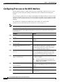
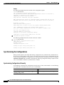
To configure IP access on the NME port fastethernet 0 from the CLI, perform these steps from the
console interface:
Step 1
Command
Purpose
Switch> enable
Enters privileged EXEC mode.
Switch#
Step 2
Switch# show hardware
Verifies the installed hardware part numbers and serial
numbers.
Step 3
Switch# configure terminal
Enters global configuration mode.
Switch(config)#
Step 4
Switch(config)# enable password [level
level] password
Sets the enable password. You can specify one of 16
privilege levels, using numbers 0 through 15. Level 1
is normal EXEC-mode user privileges. The default
level is 15 (traditional enable privileges).
Step 5
Switch(config)# enable secret [level level]
password
Specifies an enable secret password. You can specify
one of 16 privilege levels, using numbers 0 through 15.
Level 1 is normal EXEC-mode user privileges. The
default level is 15 (traditional enable privileges).
Step 6
Switch(config)# privilege mode {level level | Configures or resets the privilege level to allow access
reset} command-string
to a specific command.
Note
Step 7
Switch(config)# interface fastethernet 0
Configure the password for a privilege level
defined using the privilege command with the
enable secret command.
Switch(config-if)#
Enters interface configuration mode on interface
fastethernet 0, the NME port on the active CPU switch
module.
Step 8
Switch(config-if)# ip address ip-address
subnet-mask
Specifies the IP address and IP subnet mask for the
management port interface.
Step 9
Switch(config-if)# speed {10 | 100 | auto}
Specifies the transmission speed. The default is auto
(autonegotiation).
Cisco ONS 15530 Configuration Guide and Command Reference
3-4
78-16019-02, Cisco IOS Release 12.2(18)SV2
Chapter 3
Initial Configuration
Configuring IP Access on the NME Interface
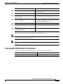
Command
Purpose
Step 10
Switch(config-if)# duplex {auto | full | half} Specifies the duplex mode. The default is auto
(autonegotiation).
Step 11
Switch(config-if)# no shutdown
Enables the interface.
Step 12
Switch(config-if)# exit
Returns to global configuration mode.
Switch(config)#
Step 13
Switch(config)# line vty line-number
Switch(config-line)#
Enters line configuration mode for virtual terminal
connections. Commands entered in this mode control
the operation of Telnet sessions.
Step 14
Switch(config-line)# password password
Specifies a password for Telnet sessions.
Step 15
Switch(config-line)# end
Returns to privileged EXEC mode.
Switch#
Step 16
Switch# copy system:running-config
nvram:startup-config
Saves the configuration changes to NVRAM.
The Cisco ONS 15530 NME interface should now be operating correctly.
Note
If a CPU switch module switchover occurs, you can use the same IP address to access the redundant
CPU switch module after it becomes active.
Note
In a multiple shelf node configuration, perform these steps on the NME interfaces on all shelves in
the node.
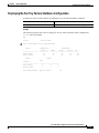
Displaying the NME Interface Configuration
To display the configuration of the NME interface, use the following EXEC command:
Command
Purpose
show interfaces fastethernet 0
Displays the NTP status.
Cisco ONS 15530 Configuration Guide and Command Reference
78-16019-02, Cisco IOS Release 12.2(18)SV2
3-5
Chapter 3
Initial Configuration
Configuring the Host Name
Example
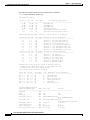
Switch# show interfaces fastethernet 0
FastEthernet0 is up, line protocol is up
Hardware is AmdFE, address is 0000.1644.28ea (bia 0000.1644.28ea)
Internet address is 172.20.54.152/24
MTU 1500 bytes, BW 10000 Kbit, DLY 1000 usec,
reliability 255/255, txload 1/255, rxload 1/255
Encapsulation ARPA, loopback not set
Keepalive set (10 sec)
Half-duplex, 10Mb/s, 100BaseTX/FX
ARP type: ARPA, ARP Timeout 04:00:00
Last input 00:00:00, output 00:00:00, output hang never
Last clearing of "show interface" counters never
Input queue: 0/75/0/0 (size/max/drops/flushes); Total output drops: 0
Queueing strategy: fifo
Output queue :0/40 (size/max)
5 minute input rate 3000 bits/sec, 6 packets/sec
5 minute output rate 1000 bits/sec, 3 packets/sec
36263 packets input, 3428728 bytes
Received 17979 broadcasts, 0 runts, 0 giants, 0 throttles
0 input errors, 0 CRC, 0 frame, 0 overrun, 0 ignored
0 watchdog
0 input packets with dribble condition detected
20363 packets output, 4279598 bytes, 0 underruns
0 output errors, 8 collisions, 0 interface resets
0 babbles, 0 late collision, 72 deferred
0 lost carrier, 0 no carrier
0 output buffer failures, 0 output buffers swapped out
Displaying the Operating Configurations
You can display the configuration file when you are in privileged EXEC (enable) mode.
•
To see the current operating configuration, enter the following command at the enable prompt:
Switch# more system:running-config
•
To see the configuration saved in NVRAM, enter the following command:
Switch# more nvram:startup-config
If you made changes to the configuration, but did not yet write the changes to NVRAM, the contents of
the running-config file will differ from the contents of the startup-config file.
Configuring the Host Name
In addition to passwords and an IP address, your initial configuration should include the host name to
make it easier to configure and troubleshoot the Cisco ONS 15530. To configure the host name, perform
the following steps:
Step 1
Command
Purpose
Switch# configure terminal
Enters global configuration mode.
Switch(config)#
Step 2
Switch(config)# hostname name
Specifies a system name.
Cisco ONS 15530 Configuration Guide and Command Reference
3-6
78-16019-02, Cisco IOS Release 12.2(18)SV2
Chapter 3
Initial Configuration
About NTP
Step 3
Command
Purpose
name(config)# end
Returns to privileged EXEC mode. The prompt indicates
that the host name has been set to the new name.
name#
Step 4
name# copy system:running-config
nvram:startup-config
Note
The host name is also synchronized with the standby CPU switch module. The host name prompt on
the standby CPU switch module appears with “sby-” as a prefix.
Saves your configuration changes to NVRAM.
Example
The following example shows how to configure a new host name, beginning in privileged EXEC mode:
Switch# configure terminal
Switch(config)# hostname ONS15530
ONS15530(config)# end
ONS15530# copy system:running-config nvram:startup-config
About NTP
The NTP (Network Time Protocol) is a utility for synchronizing system clocks over the network,
providing a precise time base for networked workstations and servers. In the NTP model, a hierarchy of
primary and secondary servers pass timekeeping information by way of the Internet to cross-check
clocks and correct errors arising from equipment or propagation failures.
An NTP server must be accessible by the client switch. NTP runs over UDP (User Datagram Protocol),
which in turn runs over IP. NTP is documented in RFC 1305. All NTP communication uses UTC
(Coordinated Universal Time), which is the same as Greenwich Mean Time. An NTP network usually
gets its time from an authoritative time source, such as a radio clock or an atomic clock attached to a
time server. NTP distributes this time across the network. NTP is extremely efficient; no more than one
packet per minute is necessary to synchronize two machines to within a millisecond of one another.
NTP uses a stratum to describe how many NTP hops away a machine is from an authoritative time
source. A stratum 1 time server has a radio or atomic clock directly attached, a stratum 2 time server
receives its time from a stratum 1 time server, and so on. A machine running NTP automatically chooses
as its time source the machine with the lowest stratum number that it is configured to communicate with
through NTP. This strategy effectively builds a self-organizing tree of NTP speakers.
NTP has two ways to avoid synchronizing to a machine whose time might be ambiguous:
•
NTP never synchronizes to a machine that is not synchronized itself.
•
NTP compares the time reported by several machines and does not synchronize to a machine whose
time is significantly different from the others, even if its stratum is lower.
The communications between machines running NTP, known as associations, are usually statically
configured; each machine is given the IP address of all machines with which it should form associations.
Accurate timekeeping is possible by exchanging NTP messages between each pair of machines with an
association.
The Cisco implementation of NTP does not support stratum 1 service; it is not possible to connect to a
radio or atomic clock. We recommend that you obtain the time service for your network from the public
NTP servers available in the IP Internet. If the network is isolated from the Internet, the Cisco NTP
Cisco ONS 15530 Configuration Guide and Command Reference
78-16019-02, Cisco IOS Release 12.2(18)SV2
3-7
Chapter 3
Initial Configuration
Configuring NTP
implementation allows a machine to be configured so that it acts as though it is synchronized using NTP,
when in fact it has determined the time using other means. Other machines then synchronize to that
machine using NTP.
A number of manufacturers include NTP software for their host systems, and a version for systems
running UNIX and its various derivatives is also publicly available. This software allows host systems
to be time-synchronized as well.
Configuring NTP
NTP services are enabled on all interfaces by default. You can configure your Cisco ONS 15530 in either
of the following NTP associations:
•
Peer association—This system either synchronizes to the other system or allows the other system to
synchronize to it.
•
Server association—This system synchronizes to the other system, and not the other way around.
From global configuration mode, use the following procedure to configure NTP in a server association
that transmits broadcast packets and periodically updates the calendar:
Command
Purpose
Step 1
Switch(config)# ntp update-calendar
Updates hardware calendar with NTP time.
Step 2
Switch(config)# ntp server ip-address
Forms a server association with another system. You can
specify multiple associations.
Step 3
Switch(config)# end
Returns to privileged EXEC mode.
Switch#
Step 4
Switch# copy system:running-config
nvram:startup-config
Saves your configuration changes to NVRAM.
For information on other optional NTP configurations, see the Cisco IOS Configuration Fundamentals
Configuration Guide.
Displaying the NTP Configuration
To view the current NTP configuration and status, use the following EXEC command:
Command
Purpose
show ntp status
Displays the NTP status.
Example
The following example shows the NTP configuration and status:
Switch# show ntp status
Clock is synchronized, stratum 4, reference is 198.92.30.32
nominal freq is 250.0000 Hz, actual freq is 249.9999 Hz, precision is 2**24
reference time is B6C04F19.41018C62 (18:21:13.253 UTC Thu Feb 27 1997)
clock offset is 7.7674 msec, root delay is 113.39 msec
root dispersion is 386.72 msec, peer dispersion is 1.57 msec
Cisco ONS 15530 Configuration Guide and Command Reference
3-8
78-16019-02, Cisco IOS Release 12.2(18)SV2
Chapter 3
Initial Configuration
Configuring Security Features
Configuring Security Features
The Cisco ONS 15530 supports the following Cisco IOS software security features:
•
AAA (authentication, authorization, and accounting)
•
Kerberos
•
RADIUS
•
TACACS+
•
Traffic filters and firewalls
•
Passwords and privileges
Configuring AAA
This section describes the AAA features supported by the Cisco ONS 15530.
Configuring Authentication
To configure AAA authentication, perform the following tasks:
Step 1
Enable AAA by using the aaa new-model global configuration command.
Step 2
Configure security protocol parameters, such as RADIUS, TACACS+, or Kerberos if you are using a
security server. Refer to the “Configuring RADIUS” chapter, the “Configuring TACACS+” chapter, or
the “Configuring Kerberos” chapter in the Cisco IOS Security Configuration Guide.
Step 3
Define the method lists for authentication by using an AAA authentication command.
Step 4
Apply the method lists to a particular interface or line, if required.
Refer to the “Configuring Authentication” chapter in the Cisco IOS Security Configuration Guide.
Configuring Authorization
The AAA authorization feature enables you to limit the services available to a user. When AAA
authorization is enabled, the network access server uses information retrieved from the user's profile,
which is located either in the local user database or on the security server, to configure the user's session.
Once this is done, the user is granted access to a requested service only if the information in the user
profile allows it.
Refer to the “Configuring Authorization” chapter in the Cisco IOS Security Configuration Guide.
Configuring Accounting
The AAA accounting feature enables you to track the services that users are accessing and the amount
of network resources that they are consuming. When AAA accounting is enabled, the network access
server reports user activity to the TACACS+ or RADIUS security server (depending on which security
Cisco ONS 15530 Configuration Guide and Command Reference
78-16019-02, Cisco IOS Release 12.2(18)SV2
3-9
Chapter 3
Initial Configuration
Configuring Security Features
method you have implemented) in the form of accounting records. Each accounting record contains
accounting attribute-value (AV) pairs and is stored on the security server. This data can then be analyzed
for network management, client billing, and auditing.
Refer to the “Configuring Accounting” chapter in the Cisco IOS Security Configuration Guide.
Configuring Kerberos
For hosts and the KDC in your Kerberos realm to communicate and mutually authenticate, you must
identify them to each other. To do this, you add entries for the hosts to the Kerberos database on the KDC
and add SRVTAB files generated by the KDC to all hosts in the Kerberos realm. You also make entries
for users in the KDC database.
Refer to the “Configuring Kerberos” chapter in the Cisco IOS Security Configuration Guide.
Configuring RADIUS
RADIUS is a distributed client/server system that secures networks against unauthorized access.
RADIUS clients run on ATM switch router systems and send authentication requests to a central
RADIUS server that contains all user authentication and network service access information. RADIUS
is a fully open protocol, distributed in source code format, that can be modified to work with any security
system currently available.
To configure RADIUS on your Cisco router or access server, perform the following tasks:
Step 1
Use the aaa new-model global configuration command to enable AAA. AAA must be configured if you
plan to use RADIUS. Refer to the “AAA Overview” chapter in the Cisco IOS Security Configuration
Guide.
Step 2
Use the aaa authentication global configuration command to define method lists for RADIUS
authentication.Refer to the “Configuring Authentication” chapter in the Cisco IOS Security
Configuration Guide.
Step 3
Use line and interface commands to enable the defined method lists to be used. Refer to the
“Configuring Authentication” chapter in the Cisco IOS Security Configuration Guide.
The following configuration tasks are optional:
•
You may use the aaa group server command to group selected RADIUS hosts for specific services.
•
You may use the aaa dnis map command to select RADIUS server groups based on DNIS number.
To use this command, you must define RADIUS server groups using the aaa group server
command.
•
You may use the aaa authorization global command to authorize specific user functions. Refer to
the “Configuring Authorization” chapter in the Cisco IOS Security Configuration Guide.
•
You may use the aaa accounting command to enable accounting for RADIUS connections. Refer
to the “Configuring Accounting” chapter in the Cisco IOS Security Configuration Guide.
•
You may use the dialer aaa interface configuration command to create remote site profiles that
contain outgoing call attributes on the AAA server.
Refer to the “Configuring RADIUS” chapter in the Cisco IOS Security Configuration Guide.
Cisco ONS 15530 Configuration Guide and Command Reference
3-10
78-16019-02, Cisco IOS Release 12.2(18)SV2
Chapter 3
Initial Configuration
Configuring Security Features
Configuring TACACS+
To configure your router to support TACACS+, perform the following tasks:
Step 1
Use the aaa new-model global configuration command to enable AAA. AAA must be configured if you
plan to use TACACS+. Refer to the “AAA Overview” chapter in the Cisco IOS Security Configuration
Guide.
Step 2
Use the tacacs-server host command to specify the IP address of one or more TACACS+ daemons. Use
the tacacs-server key command to specify an encryption key that is used to encrypt all exchanges
between the network access server and the TACACS+ daemon. This same key must also be configured
on the TACACS+ daemon.
Step 3
Use the aaa authentication global configuration command to define method lists that use TACACS+ for
authentication. Refer to the “Configuring Authentication” chapter in the Cisco IOS Security
Configuration Guide.
Step 4
Use line and interface commands to apply the defined method lists to various interfaces. Refer to the
“Configuring Authentication” chapter in the Cisco IOS Security Configuration Guide.
Step 5
If needed, use the aaa authorization global command to configure authorization for the network access
server. Unlike authentication, which can be configured per line or per interface, authorization is
configured globally for the entire network access server. Refer to the “Configuring Authorization”
chapter in the Cisco IOS Security Configuration Guide.
Step 6
If needed, use the aaa accounting command to enable accounting for TACACS+ connections. Refer to
the “Configuring Accounting” chapter in the Cisco IOS Security Configuration Guide.
Refer to the “Configuring TACACS+” chapter in the Cisco IOS Security Configuration Guide.
Configuring Traffic Filters and Firewalls
The Cisco ONS 15530 supports the traffic filter and firewall features provided by Cisco IOS.
Traffic filters provide basic traffic filtering capabilities with access control lists (also referred to as
access lists). Access lists can be configured for all routed network protocols (IP, AppleTalk, and so on)
to filter the packets of those protocols as the packets pass through a system. You can configure access
lists on your Cisco ONS 15530 to control access to a network, preventing certain traffic from entering
or exiting a network.
Firewalls are networking devices that control access to your organization's network assets. You can
position firewalls to control access at the entrance points into your network. or to control access to a
specific part of your network
Refer to the “Traffic Filtering and Firewalls” part in the Cisco IOS Security Configuration Guide.
Configuring Passwords and Privileges
Using passwords and assigning privilege levels is a simple way of providing terminal access control in
your network. You can configure up to 16 different privilege levels and assign each level to a password.
For each privilege level you define a subset of Cisco IOS commands that can be executed. You can use
these different levels to allow some users the ability to execute all Cisco IOS commands, and to restrict
other users to a defined subset of commands.
Cisco ONS 15530 Configuration Guide and Command Reference
78-16019-02, Cisco IOS Release 12.2(18)SV2
3-11
Chapter 3
Initial Configuration
About CPU Switch Module Redundancy
Refer to the “Configuring Passwords and Privileges” part in the Cisco IOS Security Configuration Guide.
About CPU Switch Module Redundancy
The Cisco ONS 15530 supports fault tolerance by allowing the standby CPU switch module to take over
if the active CPU switch module fails. This standby, or redundant, CPU switch module runs in
hot-standby state. In hot-standby state, the standby CPU switch module is partially booted with Cisco
IOS software, but no configuration is loaded.
At the time of a switchover from the active CPU switch module, the standby CPU switch module
becomes active and loads the configuration as follows:
•
If the running configuration file on the active and standby CPU switch modules match, the new
active CPU switch module uses the running configuration file.
•
If the running configuration file on the new active CPU switch module is missing or invalid, the new
active CPU switch module uses the startup configuration file in its NVRAM (not the NVRAM of the
former active CPU switch module).
The former active CPU switch module then reloads and becomes the standby CPU switch module.
Note
If the standby CPU switch module is unavailable, the system reports a minor alarm. Use the show
facility-alarm status command to display the redundancy alarm status.
When the Cisco ONS 15530 is powered on, the two CPU switch modules arbitrate to determine which
is the active CPU switch module and which is the standby CPU switch module. The following rules apply
during arbitration:
•
A newly inserted CPU switch module always comes up as the standby CPU switch module, except
in cases where the newly inserted card is the only one present.
•
If one of the CPU switch modules cannot boot its software image, the redundant CPU switch module
boots as the active CPU switch module, allowing you to correct the situation manually.
•
The primary route processor at the time the system is powered off continues as the primary when
the system is powered on.
•
If none of the above conditions is true, the CPU switch module in slot 6 becomes the active CPU
switch module.
During normal operation, the active CPU switch module boots completely. The standby CPU switch
module partially boots, stopping short of parsing the configuration. From this point, the active and
standby CPU switch modules communicate periodically to synchronize any system configuration
changes.
Table 3-1 describes the five CPU switch module hardware states.
Cisco ONS 15530 Configuration Guide and Command Reference
3-12
78-16019-02, Cisco IOS Release 12.2(18)SV2
Chapter 3
Initial Configuration
About CPU Switch Module Redundancy
Table 3-1
CPU Switch Module Hardware States
State
Description
Active
Processor card is currently providing clock signals and control for all system
cards. The active CPU switch module responds to the configured
management IP address.
Standby
Processor card is partially booted in hot-standby state waiting to switch over
when the active CPU switch module fails, when it is rebooted or removed,
or when a manual switchover is requested.
Nonparticipant
Processor card is in ROMMON mode, or is in the process of booting, or has
not yet reached the hot-standby state. Manual switchovers are rejected unless
the force option is used.
Not plugged in
Processor card slot is empty.
Error
Processor card is present but either the interprocess arbitration interface is
not functioning or the CPU switch module is not fully seated in the chassis
slot.
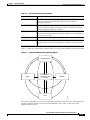
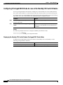
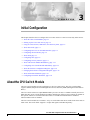
Figure 3-1 shows the valid hardware transition states for a system with redundant CPU switch modules.
Figure 3-1
CPU Switch Module State Transition Diagram
Nonparticipant
Not plugged in
(processor card
removed)
Error
Standby
58645
Active
In response to redundancy events, such as switchovers and reboots of the active CPU switch module, the
software transitions through a series of software redundancy states. Table 3-2 lists some of the
significant software states.
Cisco ONS 15530 Configuration Guide and Command Reference
78-16019-02, Cisco IOS Release 12.2(18)SV2
3-13
Chapter 3
Initial Configuration
About CPU Switch Module Redundancy
Table 3-2
CPU Switch Module Software States
State
Description
Disabled
The standby CPU switch module is not yet running the system image or is in
maintenance mode.
Standby cold
The standby CPU switch module is running the system image but has not
begun to synchronize data from the active CPU switch module.
Standby hot
The standby CPU switch module has fully synchronized the configuration and
other data from the active CPU switch module. It will remain in the
hot-standby state until a switchover occurs.
Active
The CPU switch module is in the active hardware state and has completed all
switchover or initial bootup processing. It is fully ready to control the system.
Redundant Operation Requirements
For fully redundant operation, the following requirements must be met:
•
Two CPU switch modules are required.
•
The CPU switch modules must have identical hardware configurations. This includes variables such
as DRAM size, and so on.
•
Both CPU switch modules must have the same functional image.
•
Both CPU switch modules must be running compatible system images. System images are
compatible across one major release.
•
Both the running and startup configurations are automatically synchronized between the CPU
switch modules.
•
Both CPU switch modules must be set to autoboot (a default setting).
If these requirements are met, the Cisco ONS 15530 runs in redundant mode by default. If they are not
met, the system is conditionally redundant.
Note
For detailed information on updating system images, see the “Updating System Images on Redundant
Processors” section on page 13-14.
Conditions Causing a Switchover from the Active CPU Switch Module
The following conditions can cause a switchover from the active CPU switch module to the standby CPU
switch module:
•
The active CPU switch module is removed or swapped. When the CPU switch module functioning
as the active CPU switch module is removed, the standby CPU switch module takes over. The
Cisco ONS 15530 is nonredundant until a second CPU switch module is inserted.
•
The active CPU switch module is rebooted. When a CPU switch module functioning as the active
CPU switch module is rebooted, it relinquishes its active role if the standby CPU switch module has
reached the hot-standby state.
Cisco ONS 15530 Configuration Guide and Command Reference
3-14
78-16019-02, Cisco IOS Release 12.2(18)SV2
Chapter 3
Initial Configuration
Configuring CPU Switch Module Redundancy
•
The active CPU switch module fails. The standby CPU switch module takes over as the active CPU
switch module, using the last synchronized running configuration file (or the last saved startup
configuration file if the running configuration file synchronization was disabled or failed).
•
A switchover is manually forced with the redundancy switch-activity command.
Configuring CPU Switch Module Redundancy
This section describes how to configure CPU switch module redundancy for your Cisco ONS 15530.
Note
The initial default configuration will support CPU switch module redundancy and database
synchronization with no manual configuration required.
Forcing a Switchover from Privileged EXEC Mode
You can manually force the standby CPU switch module to take over as the active CPU switch module
from privileged EXEC mode. To force a switchover from privileged EXEC mode, enter the following
command on the active CPU switch module CLI:
Command
Purpose
redundancy switch-activity [force]
Causes a CPU switch module switchover. If the
standby CPU switch module has not reached the
hot-standby software state, use the force option.
As long as you have not changed the default configuration register setting from autoboot, the standby
CPU switch module (formerly the active CPU switch module) automatically boots until it reaches the
hot-standby state.
Note
Data transmission through the system is not affected by a CPU switch module switchover.
Example
The following example shows how to manually cause a CPU switch module switchover from privileged
EXEC mode:
Switch# redundancy switch-activity
This will reload the active unit and force a switch of activity [confirm] y
Preparing to switch activity
00:12:05: %SYS-5-RELOAD: Reload requested
<Information deleted>
Cisco ONS 15530 Configuration Guide and Command Reference
78-16019-02, Cisco IOS Release 12.2(18)SV2
3-15
Chapter 3
Initial Configuration
Configuring CPU Switch Module Redundancy
Forcing a Switchover from ROM Monitor Mode
You can manually force the standby CPU switch module to take over as the active CPU switch module
ROM monitor mode. To force a switchover from ROM monitor mode, enter the following commands on
the active CPU switch module CLI:
Note
Command
Purpose
switchover
Causes a CPU switch module reset and switchover.
The CPU switch module stays in ROM monitor mode.
Using the reset command in ROM monitor mode on the active processor CLI under normal
conditions does not cause a switchover.
Example
The following example shows how to manually cause a CPU switch module switchover from ROM
monitor mode:
<Information deleted>
This CPU is ACTIVE (sev=0), peer CPU is NON-PARTICIPANT (sev=2)
MANHATTAN_OPTICAL platform with 131072 Kbytes of main memory
rommon 1 > switchover
System Bootstrap, Version 12.1(20010726:234219) [ffrazer-lh4 102], DEVELOPMENT S
OFTWARE
Copyright (c) 1994-1999 by cisco Systems, Inc.
Flash size is 16777216
Reset Reason Register = RESET_REASON_SW_NMI (0x4)
Reset type 0x2
Reading monitor variables from NVRAM
Running reset I/O devices
Enabling interrupts
Initializing TLB
Initializing cache
Initializing required TLB entries
Initializing main memory
SDRAM DIMM size 67108864
Sizing NVRAM
Initializing PCMCIA controller
Initializing SRC FPGA
CPU arbitration
This CPU is NON-PARTICIPANT (sev=2), peer CPU is ACTIVE (sev=0)
MANHATTAN_OPTICAL platform with 131072 Kbytes of main memory
rommon 1 >
Cisco ONS 15530 Configuration Guide and Command Reference
3-16
78-16019-02, Cisco IOS Release 12.2(18)SV2
Chapter 3
Initial Configuration
Configuring CPU Switch Module Redundancy
Configuring Autoboot
If you have changed the default configuration register value from autoboot, you can change it back by
performing the following steps, beginning in global configuration mode:
Command
Purpose
Step 1
Switch(config)# config-register 0x2102
Sets the configuration register for autoboot.1
Step 2
Switch(config)# boot system
bootflash:filename
Sets the BOOT environment variable. This variable
specifies the location and name of the system image
file to use when automatically booting the system.
Step 3
Switch(config)# end
Returns to privileged EXEC mode.
Switch#
Step 4
Switch# copy system:running-config
nvram:startup-config
1.
Note
Saves the configuration to NVRAM. The new
configuration register value takes effect after the next
system reload.
This is the default configuration register setting. For details on using the configuration register to set boot parameters, refer
to the Cisco IOS Configuration Fundamentals Configuration Guide.
If the standby CPU switch module remains in ROM monitor mode, you can manually boot the CPU
switch module using a system image either on the bootflash or on a Flash PC Card.
Example
The following example shows how to configure the Cisco ONS 15530 to autoboot using the first valid
file on the Flash PC Card in slot 0:
Switch(config)# config-register 0x2102
Switch(config)# boot system flash slot0:
Switch(config)# end
Switch# copy system:running-config nvram:startup-config
Displaying the Autoboot Configuration
To display the configuration register value, use the following EXEC command:
Command
Purpose
show version
Displays the configuration register value.
show bootvar
Displays the configuration register value.
Cisco ONS 15530 Configuration Guide and Command Reference
78-16019-02, Cisco IOS Release 12.2(18)SV2
3-17
Chapter 3
Initial Configuration
Configuring CPU Switch Module Redundancy
Example
The following example shows the contents of the configuration register:
Switch# show version
Cisco Internetwork Operating System Software
IOS (tm) ONS-15530 Software (manopt-M0-M), Experimental Version 12.1(20010221:0]
Copyright (c) 1986-2001 by cisco Systems, Inc.
Compiled Tue 20-Feb-01 18:40 by lthanvan
Image text-base: 0x60010968, data-base: 0x604D8000
ROM: System Bootstrap, Version 12.1(20010204:232442) [vsankar-alarm_fix 106], DE
BOOTFLASH: M1540-ODS Software (manopt-M0-M), Experimental Version 12.1(20001229]
M1 uptime is 1 minute
System returned to ROM by power-on
System image file is "tftp://171.69.1.129//tftpboot/lthanvan/manopt-m0-mz"
cisco (QUEENS-CPU) processor with 98304K/32768KB of memory.
R7000 CPU at 234Mhz, Implementation 39, Rev 2.1, 256KB L2, 2048KB L3 Cache
Last reset from unexpected value
2 Ethernet/IEEE 802.3 interface(s)
509K bytes of non-volatile configuration memory.
16384K bytes of Flash internal SIMM (Sector size 64K).
Configuration register is 0x2102
The following example shows the contents of the boot variable:
Switch# show bootvar
BOOT variable = bootflash:ons15530-i-mz.1;
CONFIG_FILE variable =
BOOTLDR variable =
Configuration register is 0x2
Standby auto-sync startup config mode is on
Standby auto-sync running config mode is on
Synchronizing the Configurations
During normal operation, the startup and running configurations are synchronized by default between
the two CPU switch modules. In the event of a switchover, the new active CPU switch module uses the
current running configuration. Configurations are synchronized either manually from the CLI using the
redundancy manual-sync command or automatically following configuration changes input from the
CLI or from SNMP if automatic synchronization is enabled.
Synchronizing Configurations Manually
To immediately synchronize the configurations used by the two CPU switch modules, use the following
privileged EXEC command on the active CPU switch module:
Command
Purpose
redundancy manual-sync {startup-config |
running-config | both}
Immediately synchronizes the configuration.
Cisco ONS 15530 Configuration Guide and Command Reference
3-18
78-16019-02, Cisco IOS Release 12.2(18)SV2
Chapter 3
Initial Configuration
Configuring CPU Switch Module Redundancy
Example
The following example shows how to manually synchronize the running configuration:
Switch# redundancy manual-sync running-config
Enabling and Disabling Automatic Synchronization
You can enable and disable automatic synchronization of the running configuration and the startup
configuration between the two CPU switch modules. Automatic synchronization ensures that, when a
switchover occurs, the standby CPU switch module has the most recent configuration information.
Note
By default, the Cisco ONS 15530 automatically synchronizes the running configuration and the
startup configuration between the two CPU switch modules.
Table 3-3 lists the events that cause the automatic synchronization of the configuration files.
Table 3-3
Synchronization Events for Configuration Files
Filename
When Synchronized
running-config
Upon exiting from global configuration mode in the CLI, or
within 5 seconds after an SNMP message that changes the
configuration
startup-config
When a new configuration is copied to NVRAM on the active
CPU switch module
To enable or disable the system to automatically synchronize the configurations on both CPU switch
modules, perform the following steps on the active CPU switch module, beginning in global
configuration mode:
Step 1
Command
Purpose
Switch(config)# redundancy
Enters redundancy configuration mode.
Switch(config-red)#
Step 2
Switch(config-red)# [no] auto-sync running-config Enables or disables synchronization of the
running configuration when it is updated. The
default state is enabled.
Step 3
Switch(config-red)# [no] auto-sync startup-config
Enables or disables synchronization of the
startup configuration when it is updated. The
default state is enabled.
Example
The following example shows how to disable automatic synchronization of the running configuration:
Switch(config)# redundancy
Switch(config-red)# no auto-sync running-config
Switch(config-red)# end
Switch# copy system:running-config nvram:startup-config
Cisco ONS 15530 Configuration Guide and Command Reference
78-16019-02, Cisco IOS Release 12.2(18)SV2
3-19
Chapter 3
Initial Configuration
Configuring CPU Switch Module Redundancy
Configuring Maintenance Mode
You can configure the Cisco ONS 15530 to enter the redundancy maintenance mode. Configuration
synchronizations and standby CPU switch module fault reporting are suppressed in maintenance mode.
Upon exiting maintenance mode and reverting to redundant mode, the standby switch CPU switch
module reboots to the hot-standby state.
Note
When the system is in maintenance mode, switchovers only occur by entering the redundancy
switch-activity force command, or physically removing the active CPU switch module.
To configure maintenance mode, perform the following steps, beginning in global configuration mode:
Step 1
Command
Purpose
Switch(config)# redundancy
Enters redundancy configuration mode.
Switch(config-red)#
Step 2
Switch(config-red)# maintenance-mode
Configures the system in maintenance mode.
Example
The following example shows how to configure redundancy maintenance mode:
Switch(config)# redundancy
Switch(config-red)# maintenance-mode
This command will place the system in SIMPLEX mode [confirm] y
Displaying the CPU Switch Module Redundancy Configuration and Status
To display the CPU switch module redundancy configuration and status, use the following privileged
EXEC commands:
Command
Purpose
show redundancy summary
Displays the redundancy configuration and status.
show redundancy capability
Displays capabilities of the active and standby CPU
switch modules and the software version that is
running.
show redundancy running-config-file
Displays the running configuration file on the standby
CPU switch module.
Note
This command is only available on a terminal
connected to the standby CPU switch module.
Cisco ONS 15530 Configuration Guide and Command Reference
3-20
78-16019-02, Cisco IOS Release 12.2(18)SV2
Chapter 3
Initial Configuration
Configuring CPU Switch Module Redundancy
Examples
The following example shows the CPU switch module redundancy configuration and status:
Switch# show redundancy summary
Redundant system information
---------------------------Available Uptime:
Time since last switchover:
Switchover Count:
3 days, 4 hours, 35 minutes
10 hours, 30 minutes
1
Inter-CPU Communication State:UP
Last Restart Reason:
Switch over
Software state at switchover: ACTIVE
Last Running Config
Running Config sync
Last Startup Config
Startup Config sync
sync:
status:
sync:
status:
2 hours, 18 minutes
In Sync
6 hours, 4 minutes
In Sync
This CPU is the Active CPU.
------------------------------Slot:
7
Time since CPU Initialized:
22 hours, 33 minutes
Image Version:
ONS-15530 Software(ONS15530-I-M),...
Image File:
bootflash:ons15530-i-mz.010727
Software Redundancy State:
ACTIVE
Hardware State:
ACTIVE
Hardware Severity:
0
Peer CPU is the Standby CPU.
------------------------------Slot:
6
Time since CPU Initialized:
10 hours, 29 minutes
Image Version:
ONS-15530 Software(ONS15530-I-M),...
Image File (on sby-CPU):
bootflash:ons15530-i-mz.010727
Software Redundancy State:
STANDBY HOT
Hardware State:
STANDBY
Hardware Severity:
0
Cisco ONS 15530 Configuration Guide and Command Reference
78-16019-02, Cisco IOS Release 12.2(18)SV2
3-21
Chapter 3
Initial Configuration
Configuring CPU Switch Module Redundancy
The following example shows the CPU switch module capabilities:
Switch# show redundancy capability
CPU capability support
Active CPU Sby CPU
Sby Compat
---------- ---------- ----------48 MB
48 MB
OK
16 MB
16 MB
OK
512 KB
512 KB
OK
16 MB
16 MB
OK
4.6
4.6
OK
1.43
1.43
OK
CPU capability description
---------------------------------------CPU DRAM size
CPU PMEM size
CPU NVRAM size
CPU Bootflash size
CPU hardware major.minor version
CPU functional major.minor version
Linecard driver major.minor versions, (counts: Active=13, Standby=13)
Active CPU Sby CPU
Sby Compat
---------- ---------- ----------1.3
1.3
OK
2.3
2.3
OK
2.1
2.1
OK
3.1
3.1
OK
1.9
1.9
OK
3.1
3.1
OK
1.9
1.9
OK
Active CPU Sby CPU
Sby Compat
---------- ---------- ----------1.3
1.3
OK
0.1
0.1
OK
2.1
2.1
OK
1.0
1.0
OK
2.1
2.1
OK
1.1
1.1
OK
Drv/Ch/F ID
----------0x1100/0/0
0x1101/0/0
0x110A/0/0
0x1105/0/0
0x1105/1/0
0x1109/0/0
0x1109/1/0
Drv/Ch/F ID
----------0x1103/0/0
0x1107/1/0
0x1102/0/0
0x110B/0/0
0x1110/0/0
0x1100/0/1
Driver description
-----------------------------CPU with Switch Fabric
10 Port ESCON line card
8 Port GE-FC line card
2.5G Transparent line card
2.5G Transparent line card
2.5G Transparent line card
2.5G Transparent line card
Driver description
-----------------------------OSC line card
OSC daughter card
10G trunk card
2.5G trunk card
PSM wdm splitter
ONS15530 Rommon
Software sync client versions, listed as version range X-Y.
X indicates the oldest peer version it can communicate with.
Y indicates the current sync client version.
Sync client counts: Active=6, Standby=6
Active CPU
---------ver 1-2
ver 1-1
ver 1-1
ver 1-2
ver 1-2
ver 1-1
Sby CPU
---------ver 1-2
ver 1-1
ver 1-1
ver 1-2
ver 1-2
ver 1-1
Sby Compat
----------OK
OK
OK
OK
OK
OK
ackplane IDPROM comparison
Backplane IDPROM field
--------------------------idversion
magic
card_type
order_part_num_str
Match
----YES
YES
YES
YES
description_str
YES
board_part_num_str
board_revision_str
serial_number_str
date_of_manufacture_str
YES
YES
YES
YES
Cl ID
----17
19
36
18
6
27
Redundancy Client description
-----------------------------------CPU Redundancy
Interface Sync
MetOpt Password Sync
Online Diagnostics
OIR Client
metopt cm db sync
Local CPU
Peer CPU
-------------------- -------------------1
1
153
153
4358
4358
PROTO-HAMPTON-CHASSIS
PROTO-HAMPTON-CHASSIS
Prototype Hampton Backplane
Prototype Hampton Backplane
73-6573-03
73-6573-03
02
02
TBC055089
TBC055089
10/21/2001
10/21/2001
Cisco ONS 15530 Configuration Guide and Command Reference
3-22
78-16019-02, Cisco IOS Release 12.2(18)SV2
Chapter 3
Initial Configuration
Configuring CPU Switch Module Redundancy
deviation_numbers_str
manufacturing_use
rma_number_str
rma_failure_code_str
oem_str
clei_str
snmp_oid_substr
schematic_num_str
Backplane IDPROM field
--------------------------hardware_major_version
hardware_minor_version
engineering_use_str
crc16
user_track_string
YES
YES
YES
YES
YES
YES
YES
YES
Match
----YES
YES
YES
OK
NO
N/A
0
N/A
0
Cisco
TBD
TBD
92-4568-03
Local CPU
-------------------3
1
LAB Prototype
52960
hello PhyAlias test
diagst
board_specific_revision
board_specific_magic_number
board_specific_length
mac_address_block_size
mac_address_base_str
cpu_number
optical_backplane_type
YES
YES
YES
YES
YES
YES
OK
YES
^A
1
153
56
16
00016447a240
0
255
Cisco
TBD
TBD
92-4568-03
Peer CPU
-------------------3
1
LAB Prototype
10284
AssetTag123
lab
^A
1
153
56
16
00016447a240
1
255
The following example shows how to display the running configuration file on the standby CPU switch
module:
sby-Switch# show redundancy running-config-file
!
version 12.1
no service pad
service timestamps debug uptime
service timestamps log uptime
no service password-encryption
no service dhcp
!
hostname Switch
<Information deleted>
Reloading the CPU Switch Modules
To reload one or both of the CPU switch modules, use the following privileged EXEC commands on the
active CPU switch module CLI:
Command
Purpose
redundancy reload peer
Reloads the standby CPU switch module.
redundancy reload shelf
Reloads both CPU switch modules in the shelf.
Example
The following example shows how to reload the standby CPU switch module:
Switch# redundancy reload peer
Reload peer [confirm] y
Preparing to reload peer
Cisco ONS 15530 Configuration Guide and Command Reference
78-16019-02, Cisco IOS Release 12.2(18)SV2
3-23
Chapter 3
Initial Configuration
Configuring CPU Switch Module Redundancy
Configuring Privileged EXEC Mode Access on the Standby CPU Switch Module
Access to privileged EXEC mode from the standby CPU switch module CLI can be enabled from the
active CPU switch module CLI. This feature provides extra security for the Cisco ONS 15530 system.
To configure access to privileged EXEC mode on the standby CPU switch module, perform the following
steps on the active CPU switch module CLI, beginning in global configuration mode:
Step 1
Command
Purpose
Switch(config)# redundancy
Enters redundancy configuration mode.
Switch(config-red)#
Step 2
Switch(config-red)# standby privilege-mode
enable
Enables access to privileged EXEC mode from the
standby CPU switch module CLI. The default state
is disabled.
Example
The following example shows how to configure redundancy maintenance mode:
Switch(config)# redundancy
Switch(config-red)# standby privilege-mode enable
Displaying the Standby CPU Switch Module Privileged EXEC Mode Status
To display the privileged EXEC mode access status on the standby CPU switch module, use the
following privileged EXEC command:
Command
Purpose
show redundancy summary
Displays the redundancy configuration and status.
Cisco ONS 15530 Configuration Guide and Command Reference
3-24
78-16019-02, Cisco IOS Release 12.2(18)SV2
Chapter 3
Initial Configuration
About the Software Configuration Register
Example
The following example shows the privileged EXEC mode access status on the standby CPU switch
module:
Switch# show redundancy summary
Redundant system information
---------------------------Available Uptime:
15 hours, 27 minutes
sysUpTime (switchover clears): 15 hours, 27 minutes
Switchover Count:
0
Inter-CPU Communication State: DOWN
Last Restart Reason:
Normal boot
Last Running Config
Running Config sync
Last Startup Config
Startup Config sync
sync:
status:
sync:
status:
never
Disabled
never
Disabled
This CPU is the Active CPU.
------------------------------Slot:
5
Time since CPU Initialized:
15 hours, 27 minutes
Image Version:
ONS-15530 Software (ONS15530-I-M), Release 12.1(10)EV
Image File:
ons15530-i-mz.evt
Software Redundancy State:
ACTIVE
Hardware State:
ACTIVE
Hardware Severity:
0
Peer CPU is the Standby CPU.
------------------------------Slot:
6
Time since CPU Initialized:
Unknown, peer CPU not responding
Image Version:
Unknown, peer CPU not responding
Image File (on sby-CPU):
Unknown, peer CPU not responding
Software Redundancy State:
DISABLED
Hardware State:
NOT PLUGGED IN
Hardware Severity:
0
Privilege Mode:
Enabled
About the Software Configuration Register
The Cisco ONS 15530 uses a 16-bit software configuration register to set specific system parameters.
Settings for the software configuration register are written into NVRAM (nonvolatile random access
memory).
You can change the software configuration register settings for the following reasons:
•
Force the system into the ROM monitor or boot ROM
•
Select a boot source and default boot filename
•
Enable or disable the break function
•
Control broadcast addresses
•
Set the console terminal baud rate
•
Load operating software from Flash memory
Cisco ONS 15530 Configuration Guide and Command Reference
78-16019-02, Cisco IOS Release 12.2(18)SV2
3-25
Chapter 3
Initial Configuration
About the Software Configuration Register
•
Enable booting from a TFTP server
•
Recover a lost password
•
Boot the system manually using the boot command at the bootstrap program prompt.
•
Force the system to boot automatically from the system bootstrap software (boot image) or from its
default system image in onboard Flash memory, using any boot system commands stored in the
startup configuration file in NVRAM
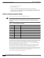
Software Configuration Register Settings
Table 3-4 describes each of the software configuration register bits.
Caution
To avoid confusion and possibly halting the system, remember that valid configuration register
settings might be combinations of settings and not just the individual settings listed in Table 3-4.
For example, the value of 0x0101 is a combination of settings (bit 8 is 0x0100 and bits 00 through 03
are 0x0001).
Table 3-4
Software Configuration Register Bits
Bit Number
Hexadecimal
Description
00 to 03
0x0000 to 0x000F
Controls the system boot behavior (also known as the boot field)
06
0x0040
Causes system software to ignore NVRAM contents
07
0x0080
Enables the OEM bit
08
0x0100
Disables the break function
09
0x0200
Uses secondary bootstrap during system boot
10
0x0400
Uses an IP broadcast with all zeros
11 to 12
0x0800 to 0x1000
Sets the console line speed (default is 9600 baud)
13
0x2000
Boots the default Flash software if network boot fails
14
0x4000
Uses IP broadcasts without network numbers
15
0x8000
Enables diagnostic messages and ignores the NVRAM contents
Bit 8 controls the console break function. Setting bit 8 (the factory default) causes the system to ignore
the console break key. Clearing bit 8 causes the system to use the break key or break signal as a command
to force the system into the bootstrap monitor (ROMMON), thereby halting normal operation.
Regardless of the setting of the break enable bit, a break causes a return to the ROMMON during the
first few seconds (approximately five seconds) of booting.
Bit 9 controls the secondary bootstrap program function. Setting bit 9 causes the system to use the
secondary bootstrap. Clearing bit 9 (the factory default) causes the system to ignore the secondary
bootstrap. The secondary bootstrap program is used for system debugging and diagnostics.
Bit 10 controls the host portion of the IP broadcast address. Setting bit 10 causes the system to use all
zeros. Clearing bit 10 (the factory default) causes the system to use all ones. Bit 10 interacts with bit 14,
which controls the network and subnet portions of the IP broadcast address.
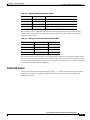
Table 3-5 shows the combined effect of bits 14 and 10.
Cisco ONS 15530 Configuration Guide and Command Reference
3-26
78-16019-02, Cisco IOS Release 12.2(18)SV2
Chapter 3
Initial Configuration
About the Software Configuration Register
Table 3-5
Register Settings for Broadcast Address
Bit 14
Bit 10
Address (<net><host>)
0
0
<ones><ones>
0
1
<ones><zeros>
1
0
<net><ones>
1
1
<net><zeros>
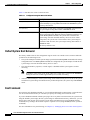
Bit 12 and bit 11 in the configuration register determine the data transmission rate of the console
terminal. Table 3-6 shows the bit settings for the four available rates. The factory-set default data
transmission rate is 9600.
Table 3-6
Settings for Console Terminal Transmission Rate
Bit 12
Bit 11
Baud Rate
0
0
9600
0
1
4800
1
0
1200
1
1
2400
Bit 13 determines the system response to a bootload failure. Setting bit 13 (the factory default) causes
the system to load operating software from bootflash memory after five unsuccessful attempts to load a
boot file from the Flash memory device in slot 0. Clearing bit 13 causes the server to continue attempting
to load a boot file from bootflash indefinitely.
Boot Field Values
The lowest four bits of the configuration register (bits 3, 2, 1, and 0) form the boot field. The order in
which the system looks for system bootstrap information depends on the boot field setting in the
configuration register.
Cisco ONS 15530 Configuration Guide and Command Reference
78-16019-02, Cisco IOS Release 12.2(18)SV2
3-27
Chapter 3
Initial Configuration
About the Software Configuration Register
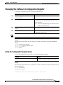
Table 3-7 describes the values for the boot field.
Table 3-7
Configuration Register Boot Field Values
Boot Field Value
Description
0x0 (0-0-0-0)
Stays at the system bootstrap prompt. You must boot the operating
system manually by giving a boot command to the ROMMON system
bootstrap environment.
0x1 (0-0-0-1)
Boots the first system image in onboard Flash SIMM. If the boot fails,
the system stops booting and remains in ROMMON mode.
0x2 (0-0-1-0) to 0xF (1-1-1-1) Loads the system image specified by boot system commands in the
startup configuration file. When the startup configuration file does not
contain boot system commands, the system tries to load the first
system image stored on the Flash memory device in slot 0. If that
attempt fails, the system tries to boot with the first system image in
bootflash. If that also fails, the system stops booting and remains in
ROMMON mode.
The factory default is 0x2.
Default System Boot Behavior
The factory default value for the configuration register on the Cisco ONS 15530 is 0x2102. When the
system boots, the following occurs:
•
The system attempts to load the system images specified in the boot system commands in the startup
configuration file. If no boot system commands are configured, the system attempts to load the first
system image stored on the Flash memory device in slot 0.
•
The console Break key sequence, or break signal, is disabled and the system ignores it while
rebooting.
Note
•
Regardless of the setting of the break enable bit, a break causes a return to the ROMMON
during the first few seconds (approximately five seconds) of booting.
After five failed attempts to load a system image on the Flash memory device in slot 0, the system
loads the first system image from Flash memory. If that attempt fails, the system stays in ROMMON
mode.
Boot Command
You can enter only the boot command, or you can include additional boot instructions, such as the name
of a file stored in Flash memory or a file that you specify for booting from a network server.
If you use the boot command without specifying a file or any other boot instructions, the system boots
using the default system image (the first system image in onboard Flash memory). Otherwise, you can
instruct the system to boot from a specific system image in Flash memory (using the boot filename
command) or by sending a direct TFTP request to a specific server (using the boot filename ip-address
command).
For more information on system booting, see Chapter 13, “Managing Your Cisco ONS 15530 System.”
Cisco ONS 15530 Configuration Guide and Command Reference
3-28
78-16019-02, Cisco IOS Release 12.2(18)SV2
Chapter 3
Initial Configuration
Changing the Software Configuration Register
Changing the Software Configuration Register
To change the configuration register, perform the following steps:
Step 1
Command
Purpose
Switch# configure terminal
Enters global configuration mode.
Switch(config)#
Step 2
Switch(config)# config-register value
Sets the contents of the configuration register. The value is
a hexadecimal number preceded by 0x. See Table 3-4 for
the list of values.
Note
Step 3
Switch(config)# end
The new configuration register value takes effect
at the next system reload.
Returns to privileged EXEC mode.
Switch#
Step 4
Switch# reload
Note
The factory default value for the register is 0x2102.
(Optional) Reloads the system using the new
configuration register value.
Example
The following example shows how to configure the system to manually boot from the ROMMON
prompt:
Switch# configuration terminal
Switch(config)# config-register 0x100
Switch(config)# end
Switch# reload
Verify the Configuration Register Value
To verify the configuration register value, use the following EXEC command:
Command
Purpose
Switch# show version
Displays the current configuration register value.
This value is used at the next system reload.
Example
The following example shows how to configure the system to examine the startup configuration file for
boot system options:
Switch# show version
<Information deleted>
Configuration register is 0x2102 (will be 0x100 at next reload)
Cisco ONS 15530 Configuration Guide and Command Reference
78-16019-02, Cisco IOS Release 12.2(18)SV2
3-29
Chapter 3
Initial Configuration
About Fan Failure Shutdown
About Fan Failure Shutdown
The Cisco ONS 15530 fan assembly is located at the bottom of the chassis and contains six individual
fans and a fan controller board. The controller board monitors the status of each fan and reports the status
to the CPU switch modules.
If a single fan fails, a minor alarm is reported to the CPU switch module. However, the chassis will never
reach a critical high temperature when only one fan fails.
If two or more fans fail, a major alarm is reported to the CPU switch module.
If all six fans in the fan tray fail, the chassis will reach critical temperature after 4 minutes.
To prevent damage to the cards and modules in the shelf when two or more fans fail, you can configure
the system to automatically reset the following cards:
•
ESCON aggregation cards
•
8-port FC/GE aggregations cards
•
2.5-Gbps ITU trunk cards
•
10-Gbps ITU trunk cards
•
Transponder line cards
In addition, the ITU lasers on the transponder line cards are powered off.
To recover from fan failure shutdown, you must power-cycle the shelf.
Caution
Do not save the startup configuration file after the line cards shutdown. This action would result in losing
the previous startup configuration.
Caution
The fan failure shutdown feature disrupts traffic on the shelf when two or more fans fail.
Configuring Fan Failure Shutdown
To configure the system to automatically shut down when two or more fans fail, use the following global
configuration command:
Note
Command
Purpose
environment-monitor shutdown fan
Enables fan tray failure shutdown.
The system will start powering off or resetting the transponder modules about 2 minutes after detecting
that two or more fans have failed.
Example
The following example shows how to enable fan tray failure shutdown:
Switch(config)# environment-monitor shutdown fan
Cisco ONS 15530 Configuration Guide and Command Reference
3-30
78-16019-02, Cisco IOS Release 12.2(18)SV2
Chapter 3
Initial Configuration
Configuring Fan Failure Shutdown
Displaying the Fan Tray Failure Shutdown Configuration
To display the fan tray failure shutdown configuration, use the following EXEC command:
Command
Purpose
show environment
Displays the fan tray failure shutdown configuration.
Example
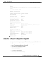
The following example shows how to display the fan tray failure shutdown feature configuration:
Switch# show environment
Fan
--Status:
Total Failure
Line card shutdown on fan failure:enabled
Sensor
-------------------Inlet Sensor
Outlet Sensor
Temperature
(degree C)
----------28
28
Sensor
Thresholds
Minor
Major
Critcal
Low
-----------------------------------65
75
80
-15
75
85
90
-15
Alarms
Min
Critical
-------------------Inlet Sensor
Outlet Sensor
-----------------------0
0
0
0
0
0
Power Entry Module 0 type DC status:
OK
Cisco ONS 15530 Configuration Guide and Command Reference
78-16019-02, Cisco IOS Release 12.2(18)SV2
3-31
Chapter 3
Initial Configuration
Configuring Fan Failure Shutdown
Cisco ONS 15530 Configuration Guide and Command Reference
3-32
78-16019-02, Cisco IOS Release 12.2(18)SV2