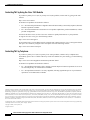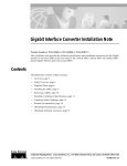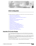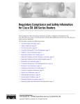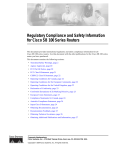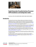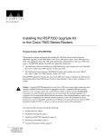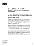
1
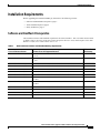
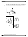
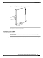
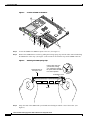
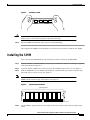
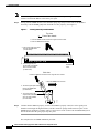
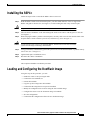
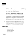
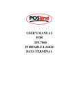
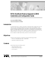
RSP4+ Bootflash Memory Upgrade to 16MB
Installation and Configuration Guide
Product Numbers: MEM-16F-RSP4+=
Customer Order Number: DOC-7812288=
Introduction
An 8 MB bootflash image is supplied with the RSP4+, RSP4, RSP2, RSP1 and RSP7000 on the Cisco
7500 series routers. This image is insufficient to store newer, larger Cisco IOS Releases, such as
12.1(4.4)T2 and 12.1(5)T, and future releases on the RSP4+. Use the instructions in this document to
upgrade to a 16-MB bootflash. Alternatively, you can use Cisco IOS Release 12.0(13)S rsp-boot-mz
image or other image, which is less than 7.7 MB in size. Contact the Technical Assistance Center (see
Technical Assistance Center, page 19) for more information on this latter alternative.
Note: The RSP8 has 16 MB of Flash memory and does not encounter this problem.
Objectives
The purpose of this document is to explain how to perform the following procedures:
•
Remove the 8-MB SIMM and install a 16-MB SIMM
•
Upgrade the bootflash memory image
Contents
This document includes the following sections:
•
Related Documentation, page 2
•
Installation Requirements, page 3
•
Overview, page 9
Corporate Headquarters:
Cisco Systems, Inc., 170 West Tasman Drive, San Jose, CA 95134-1706 USA
Copyright © 2001. Cisco Systems, Inc. All rights reserved.
78-12288-02
Related Documentation
•
Confirming the Bootflash Memory Size, page 9
•
Removing the RSP4+, page 9
•
Removing the SIMM, page 11
•
Installing the SIMM, page 13
•
Installing the RSP4+, page 15
•
Loading and Configuring the Bootflash Image, page 15
•
Obtaining Documentation, page 18
•
Obtaining Technical Assistance, page 19
Related Documentation
Your router and the Cisco IOS software running on it contain extensive features and functionality, which
are documented in the following resources:
•
Cisco IOS software:
For configuration information and support, refer to the modular configuration and modular command
reference publications in the Cisco IOS software configuration documentation set that corresponds to
the software release installed on your Cisco hardware.
Note
You can access Cisco IOS software configuration and hardware installation and
maintenance documentation on the World Wide Web at http://www.cisco.com,
http://www-china.cisco.com, or http://www-europe.cisco.com.
•
Cisco 7500 series routers:
For hardware installation and maintenance information on the Cisco 7500 series routers, refer to the
Cisco 7500 Installation and Configuration Guide that shipped with your router.
•
For international agency compliance, safety, and statutory information for WAN interfaces:
– Site Preparation and Safety Guide
– Regulatory Compliance and Safety Information for the Cisco 7500 Series Routers
•
To view Cisco documentation or obtain general information about the documentation, refer to the
following sources:
– World Wide Web, page 18
– Documentation CD-ROM, page 18
– Ordering Documentation, page 18
– Documentation Feedback, page 19
– Cisco.com, page 19
– Technical Assistance Center, page 19
RSP4+ Bootflash Memory Upgrade to 16MB Installation and Configuration Guide
2
78-12288-02
Installation Requirements
Installation Requirements
Before upgrading the bootflash SIMM, pay attention to the following sections:
•
Software and Bootflash Prerequisites, page 3
•
Tools and Parts Required, page 4
•
Safety Guidelines, page 4
Software and Bootflash Prerequisites
The minimum software and bootflash requirements are listed in Table 1. The Cisco IOS releases listed
in Table 1 apply to all Cisco 7500 series routers except for the Cisco 7576, which requires Cisco IOS
Release 11.1(22) CC or a later release of 11.1 CC.
Table 1
RSP4+ Minimum Software and Bootflash Memory Requirements
Minimum Bootflash Memory
Cisco IOS Release Version
Minimum Cisco IOS Supported Release1
Cisco IOS Release 11.1(8)CA
Cisco IOS Release 11.1(8)CA or later release of Cisco IOS Release
11.1 CA
8 MB
Cisco IOS Release 11.1(17)CC
Cisco IOS Release 11.1(17)CC or later release of Cisco IOS Release
11.1 CC
8 MB
Cisco IOS Release 11.2(6)P
Cisco IOS Release 11.2(6)P or later release of Cisco IOS Release 11.2 P
8 MB
Cisco IOS Release 11.3(1)T
Cisco IOS Release 11.3(1)T or later release of Cisco IOS Release 11.3 T
8 MB
Cisco IOS Release 11.3(1)
Cisco IOS Release 11.3(1) or later release of Cisco IOS Release 11.3
8 MB
Cisco IOS Release 12.0(1)T
Cisco IOS Release 12.0(1)T or later release of Cisco IOS Release 12.0T
8 MB
Cisco IOS Release 12.0(1)
Cisco IOS Release 12.0(1) or later release of Cisco IOS Release 12.0
8 MB
Cisco IOS Release 12.0(2)XE3
Cisco IOS Release 12.0(2)XE3 or later release of Cisco IOS Release
12.0 XE3
8 MB
Cisco IOS Release 12.0(4)XE1
Cisco IOS Release 12.0(4)XE1 or later release of Cisco IOS Release
12.0 XE1
8 MB
Cisco IOS Release 12.0(5)S
Cisco IOS Release 12.0(5)S or later release of Cisco IOS Release 12.0 S
8 MB
Cisco IOS Release 12.1(1)E
Cisco IOS Release 12.1(1)E or later release of Cisco IOS Release 12.1 E
8 MB
Cisco IOS Release 12.1(1)
Cisco IOS Release 12.1(1) or later release of Cisco IOS Release 12.1
8 MB
Cisco IOS Release 12.1(5)T
Cisco IOS Release 12.1(5)T or later release of Cisco IOS Release 12.1 T
16 MB
1.
Applies to all platforms that support the RSP4+ except Cisco 7576, which requires Cisco IOS Release 11.1(22)CC or a later release of 11.1 CC.
RSP4+ Bootflash Memory Upgrade to 16MB Installation and Configuration Guide
78-12288-02
3
Installation Requirements
Tools and Parts Required
You need the following tools and parts to install or upgrade the bootflash SIMM:
•
Number 1 Phillips and a 3/16-inch flat-blade screwdriver
•
ESD-prevention equipment or disposable grounding wrist strap included with all Cisco products
•
Antistatic mat, foam pad, or bag for the removed SIMM
If you need additional equipment, contact a service representative for ordering information.
Safety Guidelines
Following are safety guidelines that you should follow when working with any equipment that connects
to electrical power or telephone wiring.
Safety Warnings
Safety warnings appear throughout this publication in procedures that, if performed incorrectly, may
harm you. A warning symbol precedes each warning statement.
Warning
This warning symbol means danger. You are in a situation that could cause bodily
injury. Before you work on any equipment, be aware of the hazards involved with
electrical circuitry and be familiar with standard practices for preventing accidents.
To see the translations of the warnings that appear in this publication, refer to the
Regulatory Compliance and Safety Information document that accompanied this
device.
Waarschuwing
Dit waarschuwingssymbool betekent gevaar. U verkeert in een situatie die lichamelijk
letsel kan veroorzaken. Voordat u aan enige apparatuur gaat werken, dient u zich
bewust te zijn van de bij elektrische schakelingen betrokken risico's en dient u op de
hoogte te zijn van standaard maatregelen om ongelukken te voorkomen. Voor
vertalingen van de waarschuwingen die in deze publicatie verschijnen, kunt u het
document Regulatory Compliance and Safety Information (Informatie over naleving
van veiligheids- en andere voorschriften) raadplegen dat bij dit toestel is ingesloten.
Varoitus
Tämä varoitusmerkki merkitsee vaaraa. Olet tilanteessa, joka voi johtaa
ruumiinvammaan. Ennen kuin työskentelet minkään laitteiston parissa, ota selvää
sähkökytkentöihin liittyvistä vaaroista ja tavanomaisista onnettomuuksien
ehkäisykeinoista. Tässä julkaisussa esiintyvien varoitusten käännökset löydät
laitteen mukana olevasta Regulatory Compliance and Safety Information -kirjasesta
(määräysten noudattaminen ja tietoa turvallisuudesta).
RSP4+ Bootflash Memory Upgrade to 16MB Installation and Configuration Guide
4
78-12288-02
Installation Requirements
Attention
Ce symbole d'avertissement indique un danger. Vous vous trouvez dans une situation
pouvant causer des blessures ou des dommages corporels. Avant de travailler sur un
équipement, soyez conscient des dangers posés par les circuits électriques et
familiarisez-vous avec les procédures couramment utilisées pour éviter les accidents.
Pour prendre connaissance des traductions d'avertissements figurant dans cette
publication, consultez le document Regulatory Compliance and Safety Information
(Conformité aux règlements et consignes de sécurité) qui accompagne cet appareil.
Warnung
Dieses Warnsymbol bedeutet Gefahr. Sie befinden sich in einer Situation, die zu einer
Körperverletzung führen könnte. Bevor Sie mit der Arbeit an irgendeinem Gerät
beginnen, seien Sie sich der mit elektrischen Stromkreisen verbundenen Gefahren
und der Standardpraktiken zur Vermeidung von Unfällen bewußt. Übersetzungen der
in dieser Veröffentlichung enthaltenen Warnhinweise finden Sie im Dokument
Regulatory Compliance and Safety Information (Informationen zu behördlichen
Vorschriften und Sicherheit), das zusammen mit diesem Gerät geliefert wurde.
Avvertenza
Questo simbolo di avvertenza indica un pericolo. La situazione potrebbe causare
infortuni alle persone. Prima di lavorare su qualsiasi apparecchiatura, occorre
conoscere i pericoli relativi ai circuiti elettrici ed essere al corrente delle pratiche
standard per la prevenzione di incidenti. La traduzione delle avvertenze riportate in
questa pubblicazione si trova nel documento Regulatory Compliance and Safety
Information (Conformità alle norme e informazioni sulla sicurezza) che accompagna
questo dispositivo.
Advarsel
Dette varselsymbolet betyr fare. Du befinner deg i en situasjon som kan føre til
personskade. Før du utfører arbeid på utstyr, må du vare oppmerksom på de
faremomentene som elektriske kretser innebærer, samt gjøre deg kjent med vanlig
praksis når det gjelder å unngå ulykker. Hvis du vil se oversettelser av de advarslene
som finnes i denne publikasjonen, kan du se i dokumentet Regulatory Compliance and
Safety Information (Overholdelse av forskrifter og sikkerhetsinformasjon) som ble
levert med denne enheten.
Aviso
Este símbolo de aviso indica perigo. Encontra-se numa situação que lhe poderá causar
danos físicos. Antes de começar a trabalhar com qualquer equipamento,
familiarize-se com os perigos relacionados com circuitos eléctricos, e com quaisquer
práticas comuns que possam prevenir possíveis acidentes. Para ver as traduções dos
avisos que constam desta publicação, consulte o documento Regulatory Compliance
and Safety Information (Informação de Segurança e Disposições Reguladoras) que
acompanha este dispositivo.
RSP4+ Bootflash Memory Upgrade to 16MB Installation and Configuration Guide
78-12288-02
5
Installation Requirements
¡Advertencia!
Este símbolo de aviso significa peligro. Existe riesgo para su integridad física. Antes
de manipular cualquier equipo, considerar los riesgos que entraña la corriente
eléctrica y familiarizarse con los procedimientos estándar de prevención de
accidentes. Para ver una traducción de las advertencias que aparecen en esta
publicación, consultar el documento titulado Regulatory Compliance and Safety
Information (Información sobre seguridad y conformidad con las disposiciones
reglamentarias) que se acompaña con este dispositivo.
Varning!
Denna varningssymbol signalerar fara. Du befinner dig i en situation som kan leda till
personskada. Innan du utför arbete på någon utrustning måste du vara medveten om
farorna med elkretsar och känna till vanligt förfarande för att förebygga skador. Se
förklaringar av de varningar som förkommer i denna publikation i dokumentet
Regulatory Compliance and Safety Information (Efterrättelse av föreskrifter och
säkerhetsinformation), vilket medföljer denna anordning.
Installation Warning
Warning
Waarschuwing
Varoitus
Only trained and qualified personnel should be allowed to install, replace, or service
this equipment.
Deze apparatuur mag alleen worden geïnstalleerd, vervangen of hersteld door
bevoegd geschoold personeel.
Tämän laitteen saa asentaa, vaihtaa tai huoltaa ainoastaan koulutettu ja laitteen
tunteva henkilökunta.
Attention
Il est vivement recommandé de confier l'installation, le remplacement et la
maintenance de ces équipements à des personnels qualifiés et expérimentés.
Warnung
Das Installieren, Ersetzen oder Bedienen dieser Ausrüstung sollte nur geschultem,
qualifiziertem Personal gestattet werden.
Avvertenza
Questo apparato può essere installato, sostituito o mantenuto unicamente da un
personale competente.
Advarsel
Bare opplært og kvalifisert personell skal foreta installasjoner, utskiftninger eller
service på dette utstyret.
Aviso
Apenas pessoal treinado e qualificado deve ser autorizado a instalar, substituir ou
fazer a revisão deste equipamento.
¡Advertencia!
Varning!
Solamente el personal calificado debe instalar, reemplazar o utilizar este equipo.
Endast utbildad och kvalificerad personal bör få tillåtelse att installera, byta ut eller
reparera denna utrustning.
RSP4+ Bootflash Memory Upgrade to 16MB Installation and Configuration Guide
6
78-12288-02
Installation Requirements
Electrical Equipment Guidelines
Follow these basic guidelines when working with any electrical equipment:
•
Before beginning any procedures requiring access to the router interior, locate the emergency
power-off switch for the room in which you are working.
•
Disconnect all power and external cables before moving a router.
•
Do not work alone when potentially hazardous conditions exist.
•
Never assume that power has been disconnected from a circuit; always check.
•
Do not perform any action that creates a potential hazard or makes the equipment unsafe.
•
Carefully examine your work area for possible hazards such as moist floors, ungrounded power
extension cables, and missing safety grounds.
Preventing Electrostatic Discharge Damage
Electrostatic discharge (ESD) damage, which can occur when electronic cards or components are
improperly handled, results in complete or intermittent failures.
Use the following guidelines for preventing ESD damage:
Caution
•
Always use an ESD wrist or ankle strap and ensure that it makes good skin contact.
•
Connect the equipment end of the strap to an unfinished chassis surface.
•
When installing a component, use any available ejector levers or captive installation screws to
properly seat the bus connectors in the backplane.
•
When removing a component, use any available ejector levers or captive installation screws to
release the bus connectors from the backplane or midplane.
•
Handle carriers by available handles or edges only; avoid touching the printed circuit boards or
connectors.
•
Place a removed board component-side-up on an antistatic surface or in a static shielding container;
otherwise, immediately place it in a static shielding container.
•
Avoid contact between the printed circuit boards and clothing. The wrist strap only protects
components from ESD voltages on the body; ESD voltages on clothing can still cause damage.
•
Never attempt to remove the printed circuit board from the metal carrier.
For safety, periodically check the resistance value of the antistatic strap. The measurement
should be between 1 and 10 megohms (Mohm).
RSP4+ Bootflash Memory Upgrade to 16MB Installation and Configuration Guide
78-12288-02
7
Installation Requirements
Wrist Strap Warning
Warning
Waarschuwing
During this procedure, wear grounding wrist straps to avoid ESD damage to the card.
Do not directly touch the backplane with your hand or any metal tool, or you could
shock yourself.
Draag tijdens deze procedure aardingspolsbanden om te vermijden dat de kaart
beschadigd wordt door elektrostatische ontlading. Raak het achterbord niet
rechtstreeks aan met uw hand of met een metalen werktuig, omdat u anders een
elektrische schok zou kunnen oplopen.
Varoitus
Käytä tämän toimenpiteen aikana maadoitettuja rannesuojia estääksesi kortin
vaurioitumisen sähköstaattisen purkauksen vuoksi. Älä kosketa taustalevyä suoraan
kädelläsi tai metallisella työkalulla sähköiskuvaaran takia.
Attention
Lors de cette procédure, toujours porter des bracelets antistatiques pour éviter que
des décharges électriques n’endommagent la carte. Pour éviter l’électrocution, ne pas
toucher le fond de panier directement avec la main ni avec un outil métallique.
Warnung
Zur Vermeidung einer Beschädigung der Karte durch elektrostatische Entladung
während dieses Verfahrens ein Erdungsband am Handgelenk tragen. Bei Berührung
der Rückwand mit der Hand oder einem metallenen Werkzeug besteht
Elektroschockgefahr.
Avvertenza
Advarsel
Aviso
Durante questa procedura, indossare bracciali antistatici per evitare danni alla
scheda causati da un’eventuale scarica elettrostatica. Non toccare direttamente il
pannello delle connessioni, né con le mani né con un qualsiasi utensile metallico,
perché esiste il pericolo di folgorazione.
Bruk jordingsarmbånd under prosedyren for å unngå ESD-skader på kortet. Unngå
direkte berøring av bakplanet med hånden eller metallverktøy, slik at di ikke får
elektrisk støt.
Durante este procedimento e para evitar danos ESD causados à placa, use fitas de
ligação à terra para os pulsos. Para evitar o risco de choque eléctrico, não toque
directamente na parte posterior com a mão ou com qualquer ferramenta metálica.
¡Advertencia!
Usartiras conectadas a tierra en las muñecas durante este procedimiento para evitar
daños en la tarjeta causados por descargas electrostáticas. No tocar el plano
posterior con las manos ni con ninguna herramienta metálica, ya que podría producir
un choque eléctrico.
Varning!
Använd jordade armbandsremmar under denna procedur för att förhindra
elektrostatisk skada på kortet. Rör inte vid baksidan med handen eller metallverktyg
då detta kan orsaka elektrisk stöt.
RSP4+ Bootflash Memory Upgrade to 16MB Installation and Configuration Guide
8
78-12288-02
Overview
Overview
Bootflash is a single inline memory module (SIMM) with a bootloader image that allows the router to
access the Cisco IOS image when powering up or initializing the system. Bootloader images can be
downloaded over the network, or from a local server. Refer to Table 1 for a list of IOS images that require
a 16MB bootflash.
In this document, you will perform the following steps to upgrade the bootflash to 16MB:
•
Confirm the bootflash size
•
Remove the RSP4+
•
Remove the 8-MB SIMM
•
Install the 16-MB SIMM
•
Reinstall the RSP4+
•
Load and configure the new bootflash
Confirming the Bootflash Memory Size
To check the bootflash memory size on your RSP4+, use the show version command. The following
example indicates that the bootflash memory size is insufficient for Cisco IOS Release 12.1(4.4)T2 and
12.1(5)T, and later releases.
Router# show version
Cisco Internetwork Operating System Software
IOS (tm) 7500 Software (C7200-J-M), Released Version 12.0(2)
Copyright (c) 1986-1998 by cisco Systems, Inc.
20480K bytes of Flash PCMCIA card at slot 0 (Sector size 128K).
8192K bytes of Flash internal SIMM (Sector size 256K)
Removing the RSP4+
The first step in upgrading the bootflash is to remove the RSP4+ from the Cisco 7500 series router.
Step 1
Attach an ESD-preventive wrist strap between you and any unpainted chassis surface.
Step 2
Turn off the system power.
Step 3
Disconnect the cables from the RSP4+.
Step 4
Use a screwdriver to loosen the captive installation screws at both ends of the board. (See Figure 1.)
Caution
Step 5
Use the ejector levers to remove or install the RSP4+. Failure to do so can cause erroneous
system error messages indicating a board failure.
Place your thumbs on the ejector levers and simultaneously pull both of the ejectors outward (in the
opposite direction from that show in c in Figure 1) to release the RSP4+ from the backplane connector.
RSP4+ Bootflash Memory Upgrade to 16MB Installation and Configuration Guide
78-12288-02
9
Removing the RSP4+
Step 6
Use the RSP4+ handle to carefully pull it straight out of the slot, keeping your other hand under the
carrier to guide it. (See Figure 2.) Keep the RSP4+ parallel to the backplane. Avoid touching the board
or any connector pins.
Step 7
Place the removed RSP4+ on an antistatic mat or foam pad for installation later in this procedure.
Figure 1
Ejector Levers and Captive Installation Screws on the RSP4+—Vertical Orientation Shown
Bottom ejector lever
Processor
module
carrier guide
Processor module
slot
c
H1482a
STOP!
on contact
RSP4+ Bootflash Memory Upgrade to 16MB Installation and Configuration Guide
10
78-12288-02
Removing the SIMM
Handling the RSP4+ During Removal and Installation
H1355a
Figure 2
This completes the RSP4+ removal procedure.
Removing the SIMM
After removing the RSP4+ from the Cisco 7500 series router, remove the 8-MB SIMM, using the
following procedure.
Step 1
Position the RSP4+ so that the handle is away from you and the bus connector is toward you—opposite
of the position shown in Figure 2.
RSP4+ Bootflash Memory Upgrade to 16MB Installation and Configuration Guide
78-12288-02
11
Removing the SIMM
Figure 3
Location of SIMM on the RSP4+
2
1
3
MAL
NOR
U15
H7188
9
U12
1
SLOT
0
SLOT
U7
AUX
RO
UT
ES
8
CONS
7
OLE
WIT
CH
PR
OC
ES
SO
R1
6
6
4
5
Step 2
Locate the SIMM. The SIMM occupies socket U1. (See Figure 3.)
Step 3
Remove the SIMM from its socket by pulling the locking spring clips on both sides outward and tilting
the SIMM free of the clips. (See Figure 4.) Be careful not to break the clips on the SIMM connector.
Figure 4
Releasing the SIMM Spring Clips
Faceplate edge of
the system card
Pull the tabs away with
your thumbs, bracing
your forefingers against
the posts. Raise the SIMM
to a vertical position.
Polarization notch
49597
SIMM
Step 4
Grasp the ends of the SIMM with your thumbs and forefingers and lift it out of the socket. (See
Figure 5.)
RSP4+ Bootflash Memory Upgrade to 16MB Installation and Configuration Guide
12
78-12288-02
Installing the SIMM
Handling a SIMM
49598
Figure 5
Caution
Step 5
To prevent ESD damage, handle the edges of the SIMM only; avoid touching the memory
module, pins, or traces (the metal fingers) along the socket edge.
Place the SIMM in an antistatic bag to protect it from ESD damage.
This completes the SIMM removal procedure. Proceed to the next section to install the new SIMM.
Installing the SIMM
After removing the 8-MB SIMM, use the following procedure to install the 16-MB SIMM.
Step 1
Position the RSP4+ so that the handle is away from you and the bus connector is toward you—opposite
of the position shown in Figure 2.
Step 2
Locate the memory SIMM socket for the insertion. The SIMM occupies socket U1. (See Figure 3.)
Step 3
Hold the SIMM between your thumbs and forefingers, component-side-up, with the connector edge
(the metal fingers) away from you. (See Figure 5.)
Note
SIMMs have a polarization notch to prevent them from being installed backwards. Hold the
SIMM with the connector edge at the bottom. (See Figure 6.)
Figure 6
SIMM Polarization Notch
H2407
Alignment holes
Connector edge
Step 4
Polarization notch
Tilt the SIMM to approximately the same angle as the socket and insert the connector edge into the
socket.
RSP4+ Bootflash Memory Upgrade to 16MB Installation and Configuration Guide
78-12288-02
13
Installing the SIMM
Note
Step 5
When inserting SIMMs, use firm but not excessive pressure. If you damage a socket, you
will have to return the RSP4+ to the factory for repair.
Gently push the SIMM into the socket until the spring clips snap over the ends of the SIMM. If
necessary, rock the SIMM gently back and forth to seat it properly. (See Figure 7.)
Figure 7
Inserting Vertically-Loaded SIMMS
Top view
Front of the chassis
1. Insert the SIMM into the socket at an angle 45° from vertical.
2. Push the SIMM down and back.
3. The socket guide posts insert
through the SIMM holes
(on both sides).
4. The locking spring will
clip the back of the SIMM
when it is fully installed
(on both sides).
Polarization
notch
Side view
1. Insert the SIMM into the socket at an angle 45° from vertical.
2. Push the SIMM down and back.
3. The socket guide posts insert
through the SIMM holes
(on both sides).
H1152
4. The locking spring will
clip the back of the SIMM
when it is fully installed
(on both sides).
Step 6
Confirm that the SIMM is properly seated. If the SIMM is properly seated, the socket guide posts
should insert through the alignment holes, and the connector springs should click into place. If the
SIMM appears misaligned, carefully remove it and reseat it in the socket. Push the SIMM firmly back
into the socket until the spring clips snap into place.
This completes the new SIMM installation procedure.
RSP4+ Bootflash Memory Upgrade to 16MB Installation and Configuration Guide
14
78-12288-02
Installing the RSP4+
Installing the RSP4+
Follow the steps below to reinstall the RSP4+ that was removed.
Step 1
Caution
Hold the RSP4+ handle with one hand and place your other hand under the carrier to support the
RSP4+ and guide it into the slot. (See Figure 2.) Avoid touching the card or any connector pins.
To prevent ESD damage, handle the RSP4+ by the handles and carrier edges only.
Step 2
Place the back of the RSP4+ in the slot and align the notch on the carrier with the groove in the slot.
(See Figure 1.)
Step 3
While keeping the RSP4+ parallel to the backplane, carefully slide it into the slot until the back of the
faceplate makes contact with the ejector levers, and then stop. (See b in Figure 1.)
Caution
Use the ejector levers to remove or install the RSP4+. Failure to do so can cause erroneous
system error messages indicating a board failure.
Step 4
Using your thumbs, simultaneously push both ejector levers inward until the RSP4+ is pushed entirely
into its slot. (See c in Figure 1.)
Step 5
Tighten both captive installation screws.
Step 6
Reconnect the cables to the RSP4+.
This completes theRSP4+ installation procedure.
Loading and Configuring the Bootflash Image
Using the steps in this procedure, you will:
•
Enable the router to enter privileged mode
•
Confirm the new bootflash size
•
Format the bootflash
•
Copy the rsp-boot image onto the bootflash
•
Confirm that the image has been copied to bootflash
•
Modify the configuration file to reboot using the new bootflash image
•
Configure the router to use the bootloader image in bootflash
•
Save the configuration
•
Confirm that the configuration reflects the new bootloader image
RSP4+ Bootflash Memory Upgrade to 16MB Installation and Configuration Guide
78-12288-02
15
Loading and Configuring the Bootflash Image
Step 1
Boot the router, and allow it to initialize.
Step 2
Use the enable command to enter privileged mode so you can configure the new 16MB bootflash:
Router> en
Password:
Router#
Step 3
Use the show version command to confirm the size of the bootflash. The following example shows an
16MB bootflash output:
Router#sh ver
Cisco Internetwork Operating System Software
IOS (tm) RSP Software (RSP-JSV56I-M), Version 12.1(3)T,
Copyright (c) 1986-2000 by cisco Systems, Inc.
Compiled Wed 19-Jul-00 22:18 by ccai
Image text-base: 0x60010968, data-base: 0x618D2000
RELEASE SOFTWARE (fc1)
ROM: System Bootstrap, Version 12.0(10r)S1, RELEASE SOFTWARE (fc1)
BOOTFLASH: RSP Software (RSP-BOOT-M), Version 12.0(8)S, EARLY DEPLOYMENT RELEAS)
doc-7507 uptime is 12 weeks, 3 days, 21 hours, 29 minutes
System returned to ROM by bus error at PC 0x60330F20, address 0x6229
System image file is "slot0:rsp-jsv56i-mz.121-3.T"
cisco RSP8 (R7000) processor with 131072K/8216K bytes of memory.
R7000 CPU at 250Mhz, Implementation 39, Rev 1.0, 256KB L2, 2048KB L3 Cache
Last reset from power-on
G.703/E1 software, Version 1.0.
G.703/JT2 software, Version 1.0.
X.25 software, Version 3.0.0.
SuperLAT software (copyright 1990 by Meridian Technology Corp).
Bridging software.
TN3270 Emulation software.
Chassis Interface.
1 VIP2 controller (1 FastEthernet).
1 FastEthernet/IEEE 802.3 interface(s)
2043K bytes of non-volatile configuration memory.
20480K bytes of Flash PCMCIA card at slot 0 (Sector size 128K).
16384K bytes of Flash internal SIMM (Sector size 256K).
No slave installed in slot 3.
Configuration register is 0x102
Step 4
Use the format bootflash command to format the bootflash memory, as shown in the following
example:
Router#format bootflash:
Format operation may take a while. Continue? [confirm]
Format operation will destroy all data in "bootflash:".
Formatting sector 1
Format of bootflash complete
Router#
Continue? [confirm]
RSP4+ Bootflash Memory Upgrade to 16MB Installation and Configuration Guide
16
78-12288-02
Loading and Configuring the Bootflash Image
Step 5
To copy the rsp-boot image onto the bootflash, use the following series of commands:
Router# copy tftp:rsp-boot-mz.121-5.T1 bootflash:rsp-boot-mz.121-5.T1
20575008 bytes available on device slot0, proceed? [confirm]
Address or name of remote host [1.1.1.1]?
Loading new.image from 1.1.1.1 (via Ethernet1/0):!!!!!!!!!!!!!!!!!!!!!!!!!!!!!!
!!!!!!!!!!!!!!!!!!!!!!!!!!!!!!!!!!!!!!!!!!!!!!!!!!!!!!!!!!!!!!!!!!!!!!!!!!!!!!!
!!!!!!!!!!!!!!!!!!!!!!!!!!!!!!!!!!!!!!!!!!!!!!!!!!!!!!!!!!!!!!!!!!!!!!!!!!!!!!!!
!!!!!!!!!!!!!!!!!!!!!!!!!!!!!!!!!!!!!!!!!!!!!!!!!!!!!!!!!!!!!!!!!!!!!!!!!!!!!!!!
!!!!!!!!!!!!!!!!!!!!!!!!!!!!!!!!!!!!!!!!!!!!!!!!!!!!!!!!!!!!!!!!!!!!!!!!!!!!!!!!
!!!!!!!!!!!!!!!!!!!!!!!!!!!!!!!!!!!!!!!!!!!!!!!!!!!!!!!!!!!!!!!!!!!!!!!!!!!!!!!!
!!!!!!!!!!!!!!!!!!!!!!!!!!!!!!!!!!!!!!!!!!!!!!!
[OK - 7799951/15599616 bytes]
CCCCCCCCCCCCCCCCCCCCCCCCCCCCCCCCCCCCCCCCCCCCCCCCCCCCCCCCCCCCCCCCCCCCCCCCCCCCCCCC
CCCCCCCCCCCCCCCCCCCCCCCCCCCCCCCCCCCCCCCCCCCCCCCCCCCCCCCCCCCCCCCCCCCCCCCCCCCCCCCC
CCCCCCCCCCCCCCCCCCCCCCCCCCCCCCCCCCCCCCCCCCCCCCCCCCCCCCCCCCCCCCCCCCCCCCCCCC
Router#
Note
Step 6
In the preceding example, the exclamation points (!!!) appear as the file is downloaded, and
the “C” characters signify calculation of the checksum, which is a verification that the file
has been correctly downloaded to bootflash.
Use the dir bootflash command to confirm that the image has been copied to Flash memory. The output
should display the filename of the image you copied to Flash memory (rsp11-1 in the following
example):
Router# dir bootflash:
Directory of bootflash:/
1
-rw-
5090824
Jan 01 2000 00:02:28
rsp-boot-mz.121-5.T1
7602176 bytes total (2511224 bytes free)
Router#
Step 7
To ensure that the new image is used as a bootloader, add the appropriate commands to the
configuration file. To modify the configuration file, use the configure terminal command, as follows:
Router# configure terminal
Enter configuration commands, one per line. End with CNTL/Z.
Step 8
Specify that you are changing the bootloader image, and that it will load from bootflash. Then add the
filename of the new bootloader image to be loaded from bootflash:
Router(config)# boot bootldr bootflash:rsp-boot-mz.121-5.T1
The bootloader command is automatically added to your running configuration.
Step 9
To exit configuration mode, press Ctrl-Z.
Step 10
To save the configuration, copy the new configuration to nonvolatile random-access memory
(NVRAM):
Router#
Router# copy running-config startup-config
The new bootloader image is saved in the startup-config.
RSP4+ Bootflash Memory Upgrade to 16MB Installation and Configuration Guide
78-12288-02
17
Obtaining Documentation
Step 11
Use the sh bootv command to confirm that the new bootloader image will load automatically the next
time the system boots or reinitializes.
Router#sh bootv
BOOT variable =
CONFIG_FILE variable = bootflash:startup-config
BOOTLDR variable = bootflash:rsp-boot-mz.121-5.T1
Configuration register is 0x0
This completes the procedure for loading and configuring the boot image.
Obtaining Documentation
The following sections provide sources for obtaining documentation from Cisco Systems.
World Wide Web
You can access the most current Cisco documentation on the World Wide Web at the following sites:
•
http://www.cisco.com
•
http://www-china.cisco.com
•
http://www-europe.cisco.com
Documentation CD-ROM
Cisco documentation and additional literature are available in a CD-ROM package, which ships
with your product. The Documentation CD-ROM is updated monthly and may be more current than
printed documentation. The CD-ROM package is available as a single unit or as an annual subscription.
Ordering Documentation
Cisco documentation is available in the following ways:
•
Registered Cisco Direct Customers can order Cisco Product documentation from the Networking
Products MarketPlace:
http://www.cisco.com/cgi-bin/order/order_root.pl
•
Registered Cisco.com users can order the Documentation CD-ROM through the online Subscription
Store:
http://www.cisco.com/go/subscription
•
Nonregistered Cisco.com users can order documentation through a local account representative by
calling Cisco corporate headquarters (California, USA) at 408 526-7208 or, in North America, by
calling 800 553-NETS(6387).
RSP4+ Bootflash Memory Upgrade to 16MB Installation and Configuration Guide
18
78-12288-02
Obtaining Technical Assistance
Documentation Feedback
If you are reading Cisco product documentation on the World Wide Web, you can submit technical
comments electronically. Click Feedback in the toolbar and select Documentation. After you complete
the form, click Submit to send it to Cisco.
You can e-mail your comments to [email protected].
To submit your comments by mail, for your convenience many documents contain a response card
behind the front cover. Otherwise, you can mail your comments to the following address:
Cisco Systems, Inc.
Document Resource Connection
170 West Tasman Drive
San Jose, CA 95134-9883
We appreciate your comments.
Obtaining Technical Assistance
Cisco provides Cisco.com as a starting point for all technical assistance. Customers and partners can
obtain documentation, troubleshooting tips, and sample configurations from online tools. For Cisco.com
registered users, additional troubleshooting tools are available from the TAC website.
Cisco.com
Cisco.com is the foundation of a suite of interactive, networked services that provides immediate, open
access to Cisco information and resources at anytime, from anywhere in the world. This highly
integrated Internet application is a powerful, easy-to-use tool for doing business with Cisco.
Cisco.com provides a broad range of features and services to help customers and partners streamline
business processes and improve productivity. Through Cisco.com, you can find information about Cisco
and our networking solutions, services, and programs. In addition, you can resolve technical issues with
online technical support, download and test software packages, and order Cisco learning materials and
merchandise. Valuable online skill assessment, training, and certification programs are also available.
Customers and partners can self-register on Cisco.com to obtain additional personalized information and
services. Registered users can order products, check on the status of an order, access technical support,
and view benefits specific to their relationships with Cisco.
To access Cisco.com, go to the following website:
http://www.cisco.com
Technical Assistance Center
The Cisco TAC website is available to all customers who need technical assistance with a Cisco product
or technology that is under warranty or covered by a maintenance contract.
RSP4+ Bootflash Memory Upgrade to 16MB Installation and Configuration Guide
78-12288-02
19
Obtaining Technical Assistance
Contacting TAC by Using the Cisco TAC Website
If you have a priority level 3 (P3) or priority level 4 (P4) problem, contact TAC by going to the TAC
website:
http://www.cisco.com/tac
P3 and P4 level problems are defined as follows:
•
P3—Your network performance is degraded. Network functionality is noticeably impaired, but most
business operations continue.
•
P4—You need information or assistance on Cisco product capabilities, product installation, or basic
product configuration.
In each of the above cases, use the Cisco TAC website to quickly find answers to your questions.
To register for Cisco.com, go to the following website:
http://www.cisco.com/register/
If you cannot resolve your technical issue by using the TAC online resources, Cisco.com registered users
can open a case online by using the TAC Case Open tool at the following website:
http://www.cisco.com/tac/caseopen
Contacting TAC by Telephone
If you have a priority level 1(P1) or priority level 2 (P2) problem, contact TAC by telephone and
immediately open a case. To obtain a directory of toll-free numbers for your country, go to the following
website:
http://www.cisco.com/warp/public/687/Directory/DirTAC.shtml
P1 and P2 level problems are defined as follows:
•
P1—Your production network is down, causing a critical impact to business operations if service is
not restored quickly. No workaround is available.
•
P2—Your production network is severely degraded, affecting significant aspects of your business
operations. No workaround is available.
AtmDirector, Browse with Me, CCDA, CCDE, CCDP, CCIE, CCNA, CCNP, CCSI, CD-PAC, CiscoLink, the Cisco NetWorks logo, the Cisco Powered Network logo, Cisco Systems
Networking Academy, the Cisco Systems Networking Academy logo, Fast Step, Follow Me Browsing, FormShare,FrameShare, GigaStack, IGX, Internet Quotient, IP/VC, iQ
Breakthrough, iQ Expertise, iQ FastTrack, the iQ Logo, iQ Net Readiness Scorecard, MGX, the Networkers logo, Packet, PIX, RateMUX, ScriptBuilder, ScriptShare, SlideCast,
SMARTnet, TransPath, Voice LAN, Wavelength Router, WebViewer are trademarks of Cisco Systems, Inc.; Changing the Way We Work, Live, Play, and Learn, Empowering the
Internet Generation, are service marks of Cisco Systems, Inc.; and Aironet, ASIST, BPX, Catalyst, Cisco, the Cisco Certified Internetwork Expert Logo, Cisco IOS, the Cisco IOS
logo, Cisco Systems, Cisco Systems Capital, the Cisco Systems logo, Enterprise/Solver, EtherChannel, EtherSwitch, FastHub, FastSwitch, IOS, IP/TV, LightStream, Network
Registrar, Post-Routing, Pre-Routing, Registrar, StrataView Plus, Stratm, SwitchProbe, TeleRouter, and VCO are registered trademarks of Cisco Systems, Inc. or its affiliates in
the U.S. and certain other countries.
All other brands, names, or trademarks mentioned in this document or Web site are the property of their respective owners. The use of the word partner does not imply a partnership
relationship between Cisco and any other company. (0011R)
Copyright © 2000, Cisco Systems, Inc.
All rights reserved.
RSP4+ Bootflash Memory Upgrade to 16MB Installation and Configuration Guide
20
78-12288-02