1
Catalyst 6500 Series Switch Module
Installation Guide
October 2003
Corporate Headquarters
Cisco Systems, Inc.
170 West Tasman Drive
San Jose, CA 95134-1706
USA
http://www.cisco.com
Tel: 408 526-4000
800 553-NETS (6387)
Fax: 408 526-4100
Customer Order Number: DOC-7815725=
Text Part Number: 78-15725-02
THE SPECIFICATIONS AND INFORMATION REGARDING THE PRODUCTS IN THIS MANUAL ARE SUBJECT TO CHANGE WITHOUT
NOTICE. ALL STATEMENTS, INFORMATION, AND RECOMMENDATIONS IN THIS MANUAL ARE BELIEVED TO BE ACCURATE BUT
ARE PRESENTED WITHOUT WARRANTY OF ANY KIND, EXPRESS OR IMPLIED. USERS MUST TAKE FULL RESPONSIBILITY FOR
THEIR APPLICATION OF ANY PRODUCTS.
THE SOFTWARE LICENSE AND LIMITED WARRANTY FOR THE ACCOMPANYING PRODUCT ARE SET FORTH IN THE INFORMATION
PACKET THAT SHIPPED WITH THE PRODUCT AND ARE INCORPORATED HEREIN BY THIS REFERENCE. IF YOU ARE UNABLE TO
LOCATE THE SOFTWARE LICENSE OR LIMITED WARRANTY, CONTACT YOUR CISCO REPRESENTATIVE FOR A COPY.
The following information is for FCC compliance of Class A devices: This equipment has been tested and found to comply with the limits for a Class
A digital device, pursuant to part 15 of the FCC rules. These limits are designed to provide reasonable protection against harmful interference when
the equipment is operated in a commercial environment. This equipment generates, uses, and can radiate radio-frequency energy and, if not installed
and used in accordance with the instruction manual, may cause harmful interference to radio communications. Operation of this equipment in a
residential area is likely to cause harmful interference, in which case users will be required to correct the interference at their own expense.
The following information is for FCC compliance of Class B devices: The equipment described in this manual generates and may radiate
radio-frequency energy. If it is not installed in accordance with Cisco’s installation instructions, it may cause interference with radio and television
reception. This equipment has been tested and found to comply with the limits for a Class B digital device in accordance with the specifications in
part 15 of the FCC rules. These specifications are designed to provide reasonable protection against such interference in a residential installation.
However, there is no guarantee that interference will not occur in a particular installation.
Modifying the equipment without Cisco’s written authorization may result in the equipment no longer complying with FCC requirements for Class
A or Class B digital devices. In that event, your right to use the equipment may be limited by FCC regulations, and you may be required to correct
any interference to radio or television communications at your own expense.
You can determine whether your equipment is causing interference by turning it off. If the interference stops, it was probably caused by the Cisco
equipment or one of its peripheral devices. If the equipment causes interference to radio or television reception, try to correct the interference by
using one or more of the following measures:
• Turn the television or radio antenna until the interference stops.
• Move the equipment to one side or the other of the television or radio.
• Move the equipment farther away from the television or radio.
• Plug the equipment into an outlet that is on a different circuit from the television or radio. (That is, make certain the equipment and the television
or radio are on circuits controlled by different circuit breakers or fuses.)
Modifications to this product not authorized by Cisco Systems, Inc. could void the FCC approval and negate your authority to operate the product.
The Cisco implementation of TCP header compression is an adaptation of a program developed by the University of California, Berkeley (UCB) as
part of UCB’s public domain version of the UNIX operating system. All rights reserved. Copyright © 1981, Regents of the University of California.
NOTWITHSTANDING ANY OTHER WARRANTY HEREIN, ALL DOCUMENT FILES AND SOFTWARE OF THESE SUPPLIERS ARE
PROVIDED “AS IS” WITH ALL FAULTS. CISCO AND THE ABOVE-NAMED SUPPLIERS DISCLAIM ALL WARRANTIES, EXPRESSED
OR IMPLIED, INCLUDING, WITHOUT LIMITATION, THOSE OF MERCHANTABILITY, FITNESS FOR A PARTICULAR PURPOSE AND
NONINFRINGEMENT OR ARISING FROM A COURSE OF DEALING, USAGE, OR TRADE PRACTICE.
IN NO EVENT SHALL CISCO OR ITS SUPPLIERS BE LIABLE FOR ANY INDIRECT, SPECIAL, CONSEQUENTIAL, OR INCIDENTAL
DAMAGES, INCLUDING, WITHOUT LIMITATION, LOST PROFITS OR LOSS OR DAMAGE TO DATA ARISING OUT OF THE USE OR
INABILITY TO USE THIS MANUAL, EVEN IF CISCO OR ITS SUPPLIERS HAVE BEEN ADVISED OF THE POSSIBILITY OF SUCH
DAMAGES.
CCIP, CCSP, the Cisco Arrow logo, the Cisco Powered Network mark, Cisco Unity, Follow Me Browsing, FormShare, and StackWise are trademarks
of Cisco Systems, Inc.; Changing the Way We Work, Live, Play, and Learn, and iQuick Study are service marks of Cisco Systems, Inc.; and Aironet,
ASIST, BPX, Catalyst, CCDA, CCDP, CCIE, CCNA, CCNP, Cisco, the Cisco Certified Internetwork Expert logo, Cisco IOS, the Cisco IOS logo,
Cisco Press, Cisco Systems, Cisco Systems Capital, the Cisco Systems logo, Empowering the Internet Generation, Enterprise/Solver, EtherChannel,
EtherSwitch, Fast Step, GigaStack, Internet Quotient, IOS, IP/TV, iQ Expertise, the iQ logo, iQ Net Readiness Scorecard, LightStream, MGX, MICA,
the Networkers logo, Networking Academy, Network Registrar, Packet, PIX, Post-Routing, Pre-Routing, RateMUX, Registrar, ScriptShare,
SlideCast, SMARTnet, StrataView Plus, Stratm, SwitchProbe, TeleRouter, The Fastest Way to Increase Your Internet Quotient, TransPath, and VCO
are registered trademarks of Cisco Systems, Inc. and/or its affiliates in the U.S. and certain other countries.
All other trademarks mentioned in this document or Web site are the property of their respective owners. The use of the word partner does not imply
a partnership relationship between Cisco and any other company. (0304R)
Catalyst 6500 Series Switch Module Installation Guide
Copyright © 1999–2003 Cisco Systems, Inc. All rights reserved.
C O N T E N T S
Preface xi
Audience xi
Organization xii
Conventions xii
Statement 1071—Warning Definition xiv
Related Documentation xix
Obtaining Documentation xix
Cisco.com xx
Documentation CD-ROM xx
Ordering Documentation xx
Documentation Feedback xxi
Obtaining Technical Assistance xxi
Cisco TAC Website xxii
Opening a TAC Case xxii
TAC Case Priority Definitions xxiii
Obtaining Additional Publications and Information xxiii
CHAPTER
1
Product Overview 1-1
Catalyst 6000 Series Switches 1-2
Catalyst 6500 Series Switches 1-4
Supervisor Engines 1-8
LEDs 1-12
RESET Button 1-13
CONSOLE Port 1-13
Catalyst 6500 Series Switch Module Installation Guide
78-15725-02
v
Contents
CONSOLE PORT MODE Switch 1-14
Switch Load 1-15
PCMCIA Slot 1-15
Uplink Ports 1-15
10/100 and 10/100/1000 Ethernet Switching Modules 1-16
24-Port 10BASE-FL Ethernet Switching Module (WS-X6024-10FL-MT) 1-20
48-Port 10/100/1000BASE-T Ethernet Switching Module
(WS-X6148-GE-TX) 1-21
48-Port 10/100/1000BASE-T Ethernet Switching Module
(WS-X6148V-GE-TX) 1-21
48-Port 10/100BASE-T Ethernet Switching Module (WS-X6148-RJ21V) 1-22
48-Port 10/100BASE-T Ethernet Switching Module (WS-X6148-RJ45V) 1-23
24-Port 100BASE-FX Ethernet Switching Module
(WS-X6224-100FX-MT) 1-24
48-Port 10/100BASE-T Ethernet Switching Module (WS-X6248-RJ45) 1-25
48-Port 10/100BASE-T Ethernet Switching Module (WS-X6248-TEL) 1-25
48-Port 10/100BASE-T Ethernet Switching Module (WS-X6248A-TEL) 1-26
24-Port 100BASE-FX Ethernet Switching Module
(WS-X6324-100FX-MM) 1-26
24-Port 100BASE-FX Ethernet Switching Module
(WS-X6324-100FX-SM) 1-27
48-Port 10/100BASE-T Ethernet Switching Module (WS-X6348-RJ21V) 1-28
48-Port 10/100BASE-T Ethernet Switching Module (WS-X6348-RJ-45) 1-29
48-Port 10/100BASE-T Ethernet Switching Module (WS-X6348-RJ45V) 1-30
24-Port 100BASE-FX Fabric-Enabled Ethernet Switching Module
(WS-X6524-100FX-MM) 1-31
48-Port 10/100/1000BASE-T Ethernet Switching Module
(WS-X6548-GE-TX) 1-31
Catalyst 6500 Series Switch Module Installation Guide
vi
78-15725-02
Contents
48-Port 10/100/1000BASE-T Ethernet Switching Module
(WS-X6548V-GE-TX) 1-32
48-Port 10/100BASE-T Fabric-Enabled Ethernet Switching Module
(WS-X6548-RJ-21) 1-33
48-Port 10/100BASE-T Fabric-Enabled Ethernet Switching Module
(WS-X6548-RJ-45) 1-34
48-Port 10/100/1000BASE-T Fabric-Enabled Ethernet Switching Module
(WS-X6748-GE-TX) 1-35
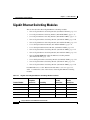
Gigabit Ethernet Switching Modules 1-36
16-Port Gigabit Ethernet Switching Module (WS-X6316-GE-TX) 1-38
8-Port Gigabit Ethernet Switching Module (WS-X6408-GBIC) 1-38
8-Port Gigabit Ethernet Switching Module (WS-X6408A-GBIC) 1-39
16-Port Gigabit Ethernet Switching Module (WS-X6416-GBIC) 1-40
16-Port Gigabit Ethernet Switching Module (WS-X6416-GE-MT) 1-41
1-Port 10-Gigabit Ethernet Module (WS-X6501-10GEX4) 1-41
1-Port 10-Gigabit Ethernet Base Module (WS-X6502-10GE) 1-42
16-Port Gigabit Ethernet Switching Module (WS-X6516-GBIC) 1-42
16-Port Gigabit Ethernet Switching Module (WS-X6516A-GBIC) 1-43
16-Port 10/100/1000BASE-T Gigabit Ethernet Switching Module
(WS-X6516-GE-TX) 1-44
4-Port 10 Gigabit Ethernet Switching Module (WS-X6704-10GE) 1-44
24-Port Gigabit Ethernet Switching Module (WS-X6724-SFP) 1-45
16-Port Gigabit Ethernet Switching Module (WS-X6816-GBIC) 1-46
Ethernet Module LEDs 1-47
ATM Modules 1-48
1-Port OC-12 ATM Module (WS-X6101-OC12-MMF) 1-49
1-Port OC-12 ATM Module (WS-X6101-OC12-SMF) 1-50
ATM Module LEDs 1-51
FlexWAN Module (WS-X6182-2PA) 1-52
Multilayer Switch Module (WS-X6302-MSM) 1-54
Catalyst 6500 Series Switch Module Installation Guide
78-15725-02
vii
Contents
Network Analysis Modules 1-58
Network Analysis Module (WS-SVC-NAM-1) 1-59
Network Analysis Module (WS-SVC-NAM-2) 1-61
Firewall Services Module (WS-SVC-FWM-1-K9) 1-63
IPSec VPN Acceleration Services Module (WS-SVC-IPSEC-1) 1-66
Intrusion Detection System Module (WS-X6381-IDS) 1-68
Content Switching Module (WS-X6066-SLB-APC) 1-71
Switch Fabric Modules 1-72
Switch Fabric Module (WS-C6500-SFM) 1-72
Switch Fabric Module 2 (WS-X6500-SFM2) 1-73
Voice-Related Modules 1-75
Communications Media Module (WS-SVC-CMM) 1-75
8-Port T1/E1 PSTN Interface Module (WS-X6608-T1/E1) 1-80
24-Port FXS Analog Interface Module (WS-X6624-FXS) 1-82
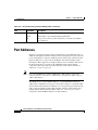
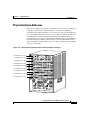
Port Addresses 1-84
Physical Interface Addresses 1-85
MAC Addresses 1-86
Hot Swapping Supervisor Engines and Switching Modules 1-87
Power Management and Environmental Monitoring 1-88
CHAPTER
2
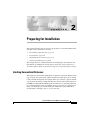
Preparing for Installation 2-1
Limiting Connection Distances 2-1
Determining Cable Distances 2-2
ATM 2-3
Ethernet and Fast Ethernet 2-4
Gigabit Ethernet 2-5
10-Gigabit Ethernet 2-7
Catalyst 6500 Series Switch Module Installation Guide
viii
78-15725-02
Contents
Patch Cord 2-9
Differential Mode Delay 2-11
Console Port Cabling Specifications—Supervisor Engine Only 2-13
Port Connector Requirements—Switching Modules Only 2-14
Port Densities 2-16
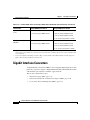
Gigabit Interface Converters 2-18
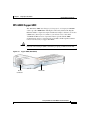
WS-G5483 Copper GBIC 2-19
WS-G5484, WS-G5486, and WS-G5487 Optical GBICs 2-20
Coarse Wave Division Multiplexing GBICs 2-21
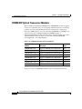
SFP Optical Transceiver Modules 2-22
1000BASE-T SFP Modules 2-23
CWDM SFP Optical Transceiver Modules 2-24
XenPak Optical Transceiver Modules 2-25
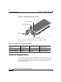
Software Requirements 2-26
CHAPTER
3
Installing the Module 3-1
Required Tools 3-2
Installing a Supervisor Engine or a Switching Module 3-2
Removing the Supervisor Engine or a Switching Module 3-12
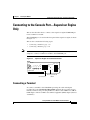
Connecting to the Console Port—Supervisor Engine Only 3-15
Connecting a Terminal 3-15
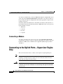
Connecting a Modem 3-16
Connecting to the Uplink Ports—Supervisor Engine Only 3-16
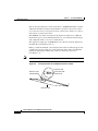
Using Flash PC Cards 3-17
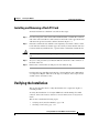
Installing and Removing a Flash PC Card 3-19
Verifying the Installation 3-19
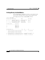
Verifying Newly Installed Modules 3-20
Checking Connectivity 3-22
What To Do After Installing Modules and Verifying Connectivity 3-22
Catalyst 6500 Series Switch Module Installation Guide
78-15725-02
ix
Contents
APPENDIX
A
Technical Specifications A-1
Module Specifications A-1
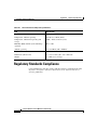
Regulatory Standards Compliance A-2
APPENDIX
B
Cable and Connector Specifications B-1
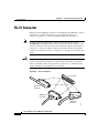
RJ-21 Connector B-2
RJ-21 (WS-X6624-FXS Only) B-4
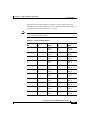
RJ-45 Connector B-5
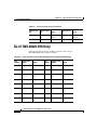
Supervisor Engine Console Port Signals and Pinouts B-8
CONSOLE PORT MODE Switch B-9
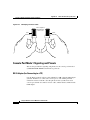
Identifying a Rollover Cable B-9
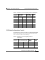
Console Port Mode 1 Signaling and Pinouts B-10
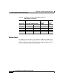
Console Port Mode 2 Signaling and Pinouts B-13
Fiber-Optic Connectors B-14
SC Connectors B-14
MT-RJ Connectors B-15
LC Connectors B-16
Cleaning the Fiber-Optic Connectors B-17
INDEX
Catalyst 6500 Series Switch Module Installation Guide
x
78-15725-02
Preface
This preface describes who should read the Catalyst 6500 Series Switch Module
Installation Guide, how it is organized, and its document conventions.
Audience
Only trained and qualified service personnel (as defined in IEC 60950 and
AS/NZS3260) should install, replace, or service the equipment described in this
publication.
Catalyst 6500 Series Switch Module Installation Guide
78-15725-02
xi
Preface
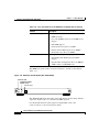
Organization
Organization
This publication is organized as follows:
Chapter
Title
Description
Chapter 1
Product Overview
Provides an overview of the Catalyst 6500 series
switches, the supervisor engine, Ethernet switching
modules, and ATM modules.
Chapter 2
Preparing for Installation Describes how to prepare your site before installing the
supervisor engine and switching modules, and includes
information on ensuring safety during installation and
preparing the necessary cabling and interface
connectors.
Chapter 3
Installing the Module
Describes how to install the supervisor engine, Ethernet
switching modules, and ATM modules in the
Catalyst 6500 series switch. Includes procedures to
verify the module operation after installation.
Appendix A
Technical Specifications
Lists the technical specifications for the Catalyst 6500
series modules.
Appendix B
Cable and Connector
Specifications
Lists the cable specifications for the Catalyst 6500
series modules.
Conventions
This publication uses the following conventions:
Convention
Description
boldface font
Commands, command options, and keywords are in boldface.
italic font
Arguments for which you supply values are in italics.
[ ]
Elements in square brackets are optional.
{x|y|z}
Alternative keywords are grouped in braces and separated by vertical bars.
Catalyst 6500 Series Switch Module Installation Guide
xii
78-15725-02
Preface
Conventions
Convention
Description
[x|y|z]
Optional alternative keywords are grouped in brackets and separated by
vertical bars.
string
A nonquoted set of characters. Do not use quotation marks around the string
or the string will include the quotation marks.
screen
font
Terminal sessions and information the system displays are in screen font.
boldface screen
font
Information you must enter is in boldface
screen
font.
italic screen font
Arguments for which you supply values are in italic screen font.
^
The symbol ^ represents the key labeled Control. For example, the key
combination ^D in a screen display means hold down the Control key while
you press the D key.
< >
Nonprinting characters, such as passwords, are in angle brackets.
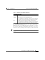
Notes use the following conventions:
Note
Means reader take note. Notes contain helpful suggestions or references to
material not covered in the publication.
Cautions use the following conventions:
Caution
Means reader be careful. In this situation, you might do something that could
result in equipment damage or loss of data.
Catalyst 6500 Series Switch Module Installation Guide
78-15725-02
xiii
Preface
Conventions
Warnings use the following conventions:
Statement 1071—Warning Definition
Warning
IMPORTANT SAFETY INSTRUCTIONS
This warning symbol means danger. You are in a situation that could cause
bodily injury. Before you work on any equipment, be aware of the hazards
involved with electrical circuitry and be familiar with standard practices for
preventing accidents. Use the statement number provided at the end of each
warning to locate its translation in the translated safety warnings that
accompanied this device.
SAVE THESE INSTRUCTIONS
Waarschuwing
BELANGRIJKE VEILIGHEIDSINSTRUCTIES
Dit waarschuwingssymbool betekent gevaar. U verkeert in een situatie die
lichamelijk letsel kan veroorzaken. Voordat u aan enige apparatuur gaat
werken, dient u zich bewust te zijn van de bij elektrische schakelingen
betrokken risico's en dient u op de hoogte te zijn van de standaard praktijken
om ongelukken te voorkomen. Gebruik het nummer van de verklaring
onderaan de waarschuwing als u een vertaling van de waarschuwing die bij
het apparaat wordt geleverd, wilt raadplegen.
BEWAAR DEZE INSTRUCTIES
Varoitus
TÄRKEITÄ TURVALLISUUSOHJEITA
Tämä varoitusmerkki merkitsee vaaraa. Tilanne voi aiheuttaa ruumiillisia
vammoja. Ennen kuin käsittelet laitteistoa, huomioi sähköpiirien
käsittelemiseen liittyvät riskit ja tutustu onnettomuuksien yleisiin
ehkäisytapoihin. Turvallisuusvaroitusten käännökset löytyvät laitteen
mukana toimitettujen käännettyjen turvallisuusvaroitusten joukosta
varoitusten lopussa näkyvien lausuntonumeroiden avulla.
SÄILYTÄ NÄMÄ OHJEET
Catalyst 6500 Series Switch Module Installation Guide
xiv
78-15725-02
Preface
Conventions
Attention
IMPORTANTES INFORMATIONS DE SÉCURITÉ
Ce symbole d'avertissement indique un danger. Vous vous trouvez dans une
situation pouvant entraîner des blessures ou des dommages corporels. Avant
de travailler sur un équipement, soyez conscient des dangers liés aux circuits
électriques et familiarisez-vous avec les procédures couramment utilisées
pour éviter les accidents. Pour prendre connaissance des traductions des
avertissements figurant dans les consignes de sécurité traduites qui
accompagnent cet appareil, référez-vous au numéro de l'instruction situé à la
fin de chaque avertissement.
CONSERVEZ CES INFORMATIONS
Warnung
WICHTIGE SICHERHEITSHINWEISE
Dieses Warnsymbol bedeutet Gefahr. Sie befinden sich in einer Situation, die
zu Verletzungen führen kann. Machen Sie sich vor der Arbeit mit Geräten mit
den Gefahren elektrischer Schaltungen und den üblichen Verfahren zur
Vorbeugung vor Unfällen vertraut. Suchen Sie mit der am Ende jeder Warnung
angegebenen Anweisungsnummer nach der jeweiligen Übersetzung in den
übersetzten Sicherheitshinweisen, die zusammen mit diesem Gerät
ausgeliefert wurden.
BEWAHREN SIE DIESE HINWEISE GUT AUF.
Avvertenza
IMPORTANTI ISTRUZIONI SULLA SICUREZZA
Questo simbolo di avvertenza indica un pericolo. La situazione potrebbe
causare infortuni alle persone. Prima di intervenire su qualsiasi
apparecchiatura, occorre essere al corrente dei pericoli relativi ai circuiti
elettrici e conoscere le procedure standard per la prevenzione di incidenti.
Utilizzare il numero di istruzione presente alla fine di ciascuna avvertenza per
individuare le traduzioni delle avvertenze riportate in questo documento.
CONSERVARE QUESTE ISTRUZIONI
Catalyst 6500 Series Switch Module Installation Guide
78-15725-02
xv
Preface
Conventions
Advarsel
VIKTIGE SIKKERHETSINSTRUKSJONER
Dette advarselssymbolet betyr fare. Du er i en situasjon som kan føre til skade
på person. Før du begynner å arbeide med noe av utstyret, må du være
oppmerksom på farene forbundet med elektriske kretser, og kjenne til
standardprosedyrer for å forhindre ulykker. Bruk nummeret i slutten av hver
advarsel for å finne oversettelsen i de oversatte sikkerhetsadvarslene som
fulgte med denne enheten.
TA VARE PÅ DISSE INSTRUKSJONENE
Aviso
INSTRUÇÕES IMPORTANTES DE SEGURANÇA
Este símbolo de aviso significa perigo. Você está em uma situação que poderá
ser causadora de lesões corporais. Antes de iniciar a utilização de qualquer
equipamento, tenha conhecimento dos perigos envolvidos no manuseio de
circuitos elétricos e familiarize-se com as práticas habituais de prevenção de
acidentes. Utilize o número da instrução fornecido ao final de cada aviso para
localizar sua tradução nos avisos de segurança traduzidos que acompanham
este dispositivo.
GUARDE ESTAS INSTRUÇÕES
¡Advertencia!
INSTRUCCIONES IMPORTANTES DE SEGURIDAD
Este símbolo de aviso indica peligro. Existe riesgo para su integridad física.
Antes de manipular cualquier equipo, considere los riesgos de la corriente
eléctrica y familiarícese con los procedimientos estándar de prevención de
accidentes. Al final de cada advertencia encontrará el número que le ayudará
a encontrar el texto traducido en el apartado de traducciones que acompaña
a este dispositivo.
GUARDE ESTAS INSTRUCCIONES
Catalyst 6500 Series Switch Module Installation Guide
xvi
78-15725-02
Preface
Conventions
Varning!
VIKTIGA SÄKERHETSANVISNINGAR
Denna varningssignal signalerar fara. Du befinner dig i en situation som kan
leda till personskada. Innan du utför arbete på någon utrustning måste du vara
medveten om farorna med elkretsar och känna till vanliga förfaranden för att
förebygga olyckor. Använd det nummer som finns i slutet av varje varning för
att hitta dess översättning i de översatta säkerhetsvarningar som medföljer
denna anordning.
SPARA DESSA ANVISNINGAR
Catalyst 6500 Series Switch Module Installation Guide
78-15725-02
xvii
Preface
Conventions
Catalyst 6500 Series Switch Module Installation Guide
xviii
78-15725-02
Preface
Related Documentation
Related Documentation
For instructions on installing and configuring Catalyst 6500 series switches, refer
to these publications:
•
Regulatory Compliance and Safety Information for the Catalyst 6500 Series
Switches
•
Site Preparation and Safety Guide
•
Catalyst 6500 Series Switch Quick Software Configuration Guide
•
Catalyst 6500 Series Switch Installation Guide
•
Catalyst 6000 Series Switch Installation Guide
•
Catalyst 6500 Series Switch Software Configuration Guide
•
Catalyst 6500 Series Switch Command Reference
•
Catalyst 6500 Series Switch Cisco IOS Software Configuration Guide
•
Catalyst 6500 Series Switch Cisco IOS Command Reference
•
ATM Software Configuration and Command Reference—Catalyst 5000
Family and Catalyst 6500 Series Switches
•
System Message Guide—Catalyst 6500 Series, Catalyst 4500 Series,
Catalyst 2948G, and Catalyst 2980G Switches
•
Installation Note for the CWDM Passive Optical System
•
For information about MIBs, refer to the following World Wide Web site:
http://www.cisco.com/public/sw-center/netmgmt/cmtk/mibs.shtml
Obtaining Documentation
Cisco provides several ways to obtain documentation, technical assistance, and
other technical resources. These sections explain how to obtain technical
information from Cisco Systems.
Catalyst 6500 Series Switch Module Installation Guide
78-15725-02
xix
Preface
Obtaining Documentation
Cisco.com
You can access the most current Cisco documentation on the World Wide Web at
this URL:
http://www.cisco.com/univercd/home/home.htm
You can access the Cisco website at this URL:
http://www.cisco.com
International Cisco websites can be accessed from this URL:
http://www.cisco.com/public/countries_languages.shtml
Documentation CD-ROM
Cisco documentation and additional literature are available in a Cisco
Documentation CD-ROM package, which may have shipped with your product.
The Documentation CD-ROM is updated regularly and may be more current than
printed documentation. The CD-ROM package is available as a single unit or
through an annual or quarterly subscription.
Registered Cisco.com users can order a single Documentation CD-ROM (product
number DOC-CONDOCCD=) through the Cisco Ordering tool:
http://www.cisco.com/en/US/partner/ordering/ordering_place_order_ordering_tool_
launch.html
All users can order annual or quarterly subscriptions through the online
Subscription Store:
http://www.cisco.com/go/subscription
Click Subscriptions & Promotional Materials in the left navigation bar.
Ordering Documentation
You can find instructions for ordering documentation at this URL:
http://www.cisco.com/univercd/cc/td/doc/es_inpck/pdi.htm
Catalyst 6500 Series Switch Module Installation Guide
xx
78-15725-02
Preface
Documentation Feedback
You can order Cisco documentation in these ways:
•
Registered Cisco.com users (Cisco direct customers) can order Cisco product
documentation from the Networking Products MarketPlace:
http://www.cisco.com/en/US/partner/ordering/index.shtml
•
Nonregistered Cisco.com users can order documentation through a local
account representative by calling Cisco Systems Corporate Headquarters
(California, USA) at 408 526-7208 or, elsewhere in North America, by
calling 800 553-NETS (6387).
Documentation Feedback
You can submit e-mail comments about technical documentation to
[email protected].
You can submit comments by using the response card (if present) behind the front
cover of your document or by writing to the following address:
Cisco Systems
Attn: Customer Document Ordering
170 West Tasman Drive
San Jose, CA 95134-9883
We appreciate your comments.
Obtaining Technical Assistance
For all customers, partners, resellers, and distributors who hold valid Cisco
service contracts, the Cisco Technical Assistance Center (TAC) provides
24-hour-a-day, award-winning technical support services, online and over the
phone. Cisco.com features the Cisco TAC website as an online starting point for
technical assistance. If you do not hold a valid Cisco service contract, please
contact your reseller.
Catalyst 6500 Series Switch Module Installation Guide
78-15725-02
xxi
Preface
Obtaining Technical Assistance
Cisco TAC Website
The Cisco TAC website (http://www.cisco.com/tac) provides online documents
and tools for troubleshooting and resolving technical issues with Cisco products
and technologies. The Cisco TAC website is available 24 hours a day, 365 days a
year.
Accessing all the tools on the Cisco TAC website requires a Cisco.com user ID
and password. If you have a valid service contract but do not have a login ID or
password, register at this URL:
http://tools.cisco.com/RPF/register/register.do
Opening a TAC Case
Using the online TAC Case Open Tool (http://www.cisco.com/tac/caseopen) is the
fastest way to open P3 and P4 cases. (P3 and P4 cases are those in which your
network is minimally impaired or for which you require product information.)
After you describe your situation, the TAC Case Open Tool automatically
recommends resources for an immediate solution. If your issue is not resolved
using the recommended resources, your case will be assigned to a Cisco TAC
engineer.
For P1 or P2 cases (P1 and P2 cases are those in which your production network
is down or severely degraded) or if you do not have Internet access, contact Cisco
TAC by telephone. Cisco TAC engineers are assigned immediately to P1 and P2
cases to help keep your business operations running smoothly.
To open a case by telephone, use one of the following numbers:
Asia-Pacific: +61 2 8446 7411 (Australia: 1 800 805 227)
EMEA: +32 2 704 55 55
USA: 1 800 553-2447
For a complete listing of Cisco TAC contacts, go to this URL:
http://www.cisco.com/warp/public/687/Directory/DirTAC.shtml
Catalyst 6500 Series Switch Module Installation Guide
xxii
78-15725-02
Preface
Obtaining Additional Publications and Information
TAC Case Priority Definitions
To ensure that all cases are reported in a standard format, Cisco has established
case priority definitions.
Priority 1 (P1)—Your network is “down” or there is a critical impact to your
business operations. You and Cisco will commit all necessary resources around
the clock to resolve the situation.
Priority 2 (P2)—Operation of an existing network is severely degraded, or
significant aspects of your business operation are negatively affected by
inadequate performance of Cisco products. You and Cisco will commit full-time
resources during normal business hours to resolve the situation.
Priority 3 (P3)—Operational performance of your network is impaired, but most
business operations remain functional. You and Cisco will commit resources
during normal business hours to restore service to satisfactory levels.
Priority 4 (P4)—You require information or assistance with Cisco product
capabilities, installation, or configuration. There is little or no effect on your
business operations.
Obtaining Additional Publications and Information
Information about Cisco products, technologies, and network solutions is
available from various online and printed sources.
•
The Cisco Product Catalog describes the networking products offered by
Cisco Systems, as well as ordering and customer support services. Access the
Cisco Product Catalog at this URL:
http://www.cisco.com/en/US/products/products_catalog_links_launch.html
•
Cisco Press publishes a wide range of general networking, training and
certification titles. Both new and experienced user will benefit from these
publications. For current Cisco Press titles and other information, go to Cisco
Press online at this URL:
http://www.ciscopress.com
•
Packet magazine is the Cisco quarterly publication that provides the latest
networking trends, technology breakthroughs, and Cisco products and
solutions to help industry professionals get the most from their networking
Catalyst 6500 Series Switch Module Installation Guide
78-15725-02
xxiii
Preface
Obtaining Additional Publications and Information
investment. Included are networking deployment and troubleshooting tips,
configuration examples, customer case studies, tutorials and training,
certification information, and links to numerous in-depth online resources.
You can access Packet magazine at this URL:
http://www.cisco.com/packet
•
iQ Magazine is the Cisco bimonthly publication that delivers the latest
information about Internet business strategies for executives. You can access
iQ Magazine at this URL:
http://www.cisco.com/go/iqmagazine
•
Internet Protocol Journal is a quarterly journal published by Cisco Systems
for engineering professionals involved in designing, developing, and
operating public and private internets and intranets. You can access the
Internet Protocol Journal at this URL:
http://www.cisco.com/en/US/about/ac123/ac147/about_cisco_the_internet_
protocol_journal.html
•
Training—Cisco offers world-class networking training. Current offerings in
network training are listed at this URL:
http://www.cisco.com/en/US/learning/index.html
Catalyst 6500 Series Switch Module Installation Guide
xxiv
78-15725-02
C H A P T E R
1
Product Overview
This chapter describes the Catalyst 6000 series switches, the Catalyst 6500 series
switches, supervisor engines, and switching modules. This chapter contains these
sections:
•
Catalyst 6000 Series Switches, page 1-2
•
Catalyst 6500 Series Switches, page 1-4
•
Supervisor Engines, page 1-8
•
10/100 and 10/100/1000 Ethernet Switching Modules, page 1-16
•
Gigabit Ethernet Switching Modules, page 1-36
•
Ethernet Module LEDs, page 1-47
•
ATM Modules, page 1-48
•
FlexWAN Module (WS-X6182-2PA), page 1-52
•
Multilayer Switch Module (WS-X6302-MSM), page 1-54
•
Network Analysis Modules, page 1-58
•
Firewall Services Module (WS-SVC-FWM-1-K9), page 1-63
Catalyst 6500 Series Switch Module Installation Guide
78-15725-02
1-1
Chapter 1
Product Overview
Catalyst 6000 Series Switches
•
IPSec VPN Acceleration Services Module (WS-SVC-IPSEC-1), page 1-66
•
Intrusion Detection System Module (WS-X6381-IDS), page 1-68
•
Content Switching Module (WS-X6066-SLB-APC), page 1-71
•
Switch Fabric Modules, page 1-72
•
Voice-Related Modules, page 1-75
•
Port Addresses, page 1-84
•
Hot Swapping Supervisor Engines and Switching Modules, page 1-87
•
Power Management and Environmental Monitoring, page 1-88
Catalyst 6000 Series Switches
The Catalyst 6000 series switches consist of the following two chassis:
•
Catalyst 6006 (6 slots)
•
Catalyst 6009 (9 slots)
These high-performance, modular, frame-based switches support high-density
Fast Ethernet and Gigabit Ethernet in both campus-backbone and
server-aggregation environments. The Catalyst 6006 and the Catalyst 6009
switches have a 32-Gbps switching capacity. Both platforms share the same
supervisor engines, switching modules, and software, and they support redundant
configurations of supervisor engines, power supplies, and port interfaces.
ATM LAN Emulation (LANE) and Multiprotocol over ATM (MPOA) support is
provided by the ATM dual PHY OC-12 LANE/MPOA module.
Note
Specific combinations of supervisor engines and modules may not be supported
in your chassis. Refer to the release notes of the software version running on your
system for specific information on modules and supervisor engine combinations
that are not supported.
Note
Throughout this publication, except where noted, the term supervisor engine is
used to refer to Supervisor Engine 1, Supervisor Engine 2, and Supervisor
Engine 720.
Catalyst 6500 Series Switch Module Installation Guide
1-2
78-15725-02
Chapter 1
Product Overview
Catalyst 6000 Series Switches
Note
The uplink ports are fully functional on the redundant supervisor engine in
standby mode.
The Catalyst 6000 series switches support the following hardware:
•
A supervisor engine with two gigabit interface uplinks and an optional
redundant supervisor engine
Note
Supervisor Engine 720 is not supported in the Catalyst 6006 and
Catalyst 6009 switches.
Both supervisor engines in a single chassis must be completely identical. You
can configure the redundant supervisor engines in a Catalyst 6000 series
switch in one of three configurations:
– Two supervisor engines, each with no Multilayer Switch Feature Card
(MSFC) and no Policy Feature Card (PFC)
– Two supervisor engines, each configured with a PFC daughter card
– Two supervisor engines, each configured with both an MSFC and a PFC
daughter card
•
Additional switching modules (Ethernet, Fast Ethernet, Gigabit Ethernet, and
ATM) in any combination
– Five additional switching modules in the Catalyst 6006
– Eight additional switching modules in the Catalyst 6009
Note
The Switch Fabric Modules are not supported in the
Catalyst 6000 series switches.
•
Hot-swappable fan assembly and modules
•
Redundant AC-input or DC-input power supplies
•
Backplane bandwidth of 32 Gbps
Catalyst 6500 Series Switch Module Installation Guide
78-15725-02
1-3
Chapter 1
Product Overview
Catalyst 6500 Series Switches
Catalyst 6500 Series Switches
The Catalyst 6500 series switches consist of the following six chassis:
•
Catalyst 6503 (3 slots)
•
Catalyst 6506 (6 slots)
•
Catalyst 6509 (9 slots)
•
Catalyst 6509-NEB (9 slots, vertical)
•
Catalyst 6509-NEB-A (9 slots, vertical)
•
Catalyst 6513 (13 slots)
The Catalyst 6506, Catalyst 6509, Catalyst 6509-NEB, Catalyst 6509-NEB-A,
and Catalyst 6513 switches can support a backplane architecture that scales from
32 Gbps to 256 Gbps. The Catalyst 6503 switch backplane architecture is limited
to 32 Gbps.
The Catalyst 6500 series switches support the following hardware:
•
A supervisor engine with two gigabit interface uplinks and an optional
redundant supervisor engine.
Note
The Supervisor Engine 720 also has a 10/100/1000 Mbps uplink port.
Both supervisor engines in a single chassis must be completely identical. You
can configure the redundant supervisor engines in a Catalyst 6500 series
switch in one of three configurations:
– Two supervisor engines, each with no Multilayer Switch Feature Card
(MSFC) and no Policy Feature Card (PFC)
– Two supervisor engines, each configured with a PFC daughter card
– Two supervisor engines, each configured with both an MSFC and a PFC
daughter card
Note
•
The Catalyst 6513 switch requires either the Supervisor Engine 2
or Supervisor Engine 720.
Additional switching modules in any combination:
Catalyst 6500 Series Switch Module Installation Guide
1-4
78-15725-02
Chapter 1
Product Overview
Catalyst 6500 Series Switches
– Two additional switching modules in the Catalyst 6503 switch
– Five additional switching modules in the Catalyst 6506 switch
– Eight additional switching modules in the Catalyst 6509,
Catalyst 6509-NEB, and Catalyst 6509-NEB-A switches
– Twelve additional switching modules in the Catalyst 6513 switch
Note
•
Specific combinations of supervisor engines and modules may
not be supported in your chassis. Refer to the release notes of the
software version running on your system for specific information
on modules and supervisor engine combinations that are not
supported.
Hot-swappable fan assembly and modules
Note
For a Supervisor Engine 720, you need to install a high-speed fan tray
and install a 2500 W or larger power supply.
•
Redundant AC-input or DC-input power supplies
•
Scalable backplane bandwidth of 32 Gbps, up to 256 Gbps
•
A Switch Fabric Module (WS-C6500-SFM or WS-X6500-SFM2)
– Only the Supervisor Engine 2 supports the Switch Fabric Module.
– Supervisor Engine 720 does not support the Switch Fabric Modules.
– Either the WS-C6500-SFM or WS-X6500-SFM2 Switch Fabric Module
can be installed in slot 5 of the Catalyst 6506, Catalyst 6509,
Catalyst 6509-NEB switches, and Catalyst 6509-NEB-A. A redundant
Switch Fabric Module can be installed in slot 6.
– Only the WS-X6500-SFM2 Switch Fabric Module can be installed in
slot 7 of the Catalyst 6513 switch. A redundant WS-X6500-SFM2
Switch Fabric Module can be installed in slot 8.
Catalyst 6500 Series Switch Module Installation Guide
78-15725-02
1-5
Chapter 1
Product Overview
Catalyst 6500 Series Switches
Note
•
For redundancy, you can install a redundant Switch Fabric
Module. The module that is installed first functions as the
primary module. When you install two Switch Fabric Modules at
the same time, the module in slot 5 or slot 7 acts as the primary
module, and the module in slot 6 or slot 8 acts as the backup. If
you reset the module in slot 5 or slot 7, the module in slot 6 or
slot 8 becomes the primary module.
A combination of an SFM (WS-C6500-SFM) with an SFM2
(WS-X6500-SFM2) in the same Catalyst 6506, Catalyst 6509, or
Catalyst 6509-NEB chassis
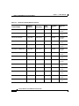
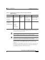
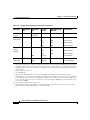
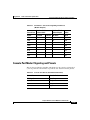
Table 1-1 lists some key features of the Catalyst 6500 series switches.
Table 1-1
Catalyst 6500 Series Switches Key Features
Feature
Description
Performance and
Configuration
Refer to the Catalyst 6500 Series Switch Software Configuration Guide or the
Catalyst 6500 Series Switch Cisco IOS Software Configuration Guide for
detailed information about the features supported on the switches.
Supervisor Engine 1
and Supervisor
Engine 2
Fault Tolerance and
Redundancy
•
Modular, upgradable feature modules for core switching logic.
•
Two modular Gigabit Ethernet ports supporting GBICs1.
•
MSFC 2 and PFC3supported.
•
PCMCIA slot.
•
Console port for terminal and modem access.
•
Support for two hot-swappable supervisor engines.
•
Fast switchover for redundant supervisor engine and switching modules.
•
Support for two fully redundant AC- or DC-input, load-sharing power
supplies.
•
Power management for modules and power supplies.
•
Environmental monitoring of critical system components.
•
Hot-swappable fan assembly. High-speed fan tray also available4.
•
Redundant clock modules.
Catalyst 6500 Series Switch Module Installation Guide
1-6
78-15725-02
Chapter 1
Product Overview
Catalyst 6500 Series Switches
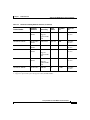
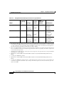
Table 1-1
Catalyst 6500 Series Switches Key Features (continued)
Feature
Description
Component
Hot-Swapping
Modules (including the supervisor engine if you have redundant supervisor
engines) and fans can be replaced without interrupting the system power or
causing other software or interfaces to shut down.
Memory
Components
•
512-KB NVRAM stores configuration information.
•
EEPROM5 component on the supervisor engine stores module-specific
information, such as the module serial number, part number, controller type,
hardware revision, configuration information, and other details unique to
each module.
•
128-MB DRAM (Supervisor Engine 1A), 128-MB DRAM (Supervisor
Engine 2), 256-MB DRAM (Supervisor Engine 2U), or 512-MB DRAM
(Supervisor Engine 720) for the default system software.
•
16-MB (Supervisor Engine 1), 32-MB (Supervisor Engine 2), or 64-MB
(Supervisor Engine 720) Flash memory stores and runs software images.
•
PC Flash—One or two slots for an optional Flash PC card, Compact Flash
card, or MicroDrive; use this additional memory to store and run software
images and configuration files, or to serve as an I/O device.
•
Flash file system—Flash memory contains a file system. You can use a
variety of commands to manage the file system (such as cd, pwd, dir, and
delete). The file system includes the following devices:
– Onboard bootflash
– PC Flash slot
Management
•
CLI through the console port or Telnet
•
Simple Network Management Protocol
1. GBICs = Gigabit Interface Converters
2. MSFC = Multilayer Switch Feature Card
3. PFC = Policy Feature Card
4. The high-speed fan tray is required if you install a Supervisor Engine 720. The high-speed fan tray requires that a 2500 W or
larger power supply be installed in the chassis.
5. EEPROM = electrically erasable programmable read-only memory
Catalyst 6500 Series Switch Module Installation Guide
78-15725-02
1-7
Chapter 1
Product Overview
Supervisor Engines
Supervisor Engines
This section describes the features found on Supervisor Engine 1, Supervisor
Engine 2, and Supervisor Engine 720. This section contains the following topics:
Note
•
LEDs, page 1-12
•
RESET Button, page 1-13
•
CONSOLE Port, page 1-13
•
CONSOLE PORT MODE Switch, page 1-14
•
Switch Load, page 1-15
•
PCMCIA Slot, page 1-15
•
Uplink Ports, page 1-15
The Catalyst 6513 switch requires a Supervisor Engine 2 or Supervisor
Engine 720.
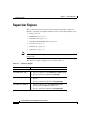
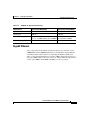
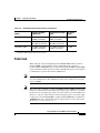
The supervisor engine configurations are listed in Table 1-2.
Table 1-2
Supervisor Engines
Product Number
Supervisor Engine
Description
11
WS-X6K-SUP1-2GE
WS-X6K-SUP1A-2GE
WS-X6K-S1A-MSFC2
•
Supervisor Engine 1, dual 1000BASE-X GBIC uplinks
•
QoS port architecture (Rx/Tx) is 1q4t/2q2t
•
Supervisor Engine 1A, dual 1000BASE-X GBIC
uplinks
•
QoS port architecture (Rx/Tx) is 1p1q4t/1p2q2t
•
Supervisor Engine 1A, dual 1000BASE-X GBIC
uplinks, PFC and MSFC2 daughter cards
•
QoS port architecture (Rx/Tx) is 1p1q4t/1p2q2t
Catalyst 6500 Series Switch Module Installation Guide
1-8
78-15725-02
Chapter 1
Product Overview
Supervisor Engines
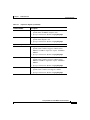
Table 1-2
Supervisor Engines (continued)
Product Number
WS-X6K-SUP1A-MSFC
WS-XSUP1A-PFC
Description
•
Supervisor Engine 1A, dual 1000BASE-X GBIC
uplinks, PFC and MSFC daughter cards
•
QoS port architecture (Rx/Tx) is 1p1q4t/1p2q2t
•
Supervisor Engine 1A, dual 1000BASE-X GBIC
uplinks, PFC daughter card
•
QoS port architecture (Rx/Tx) is 1p1q4t/1p2q2t
•
Supervisor Engine 2, dual 1000BASE-X GBIC
uplinks, fabric-enabled, supports a PFC2 and an
MSFC2, 128 MB on supervisor engine, 128 MB on
MSFC2
•
QoS port architecture (Rx/Tx) is 1p1q4t/1p2q2t
•
Supervisor Engine 2, dual 1000BASE-X GBIC
uplinks, fabric-enabled, supports a PFC2 and an
MSFC2, 256 MB on supervisor engine, 256 MB on
MSFC2
•
QoS port architecture (Rx/Tx) is 1p1q4t/1p2q2t
•
Supervisor Engine 2, dual 1000BASE-X GBIC
uplinks, fabric-enabled, and supports a PFC2
•
QoS port architecture (Rx/Tx) is 1p1q4t/1p2q2t
Supervisor Engine 2
WS-X6K-S2-MSFC2
WS-X6K-S2U-MSFC2
WS-X6K-S2-PFC2
Catalyst 6500 Series Switch Module Installation Guide
78-15725-02
1-9
Chapter 1
Product Overview
Supervisor Engines
Table 1-2
Supervisor Engines (continued)
Product Number
Description
Supervisor Engine 720
Supervisor Engine 7202
•
Two Ethernet uplink ports: port 1 supports gigabit
Small Form-Factor Pluggable (SFP) module; port 2
configurable with either a gigabit SFP or a
10/100/1000 Mbps RJ-45
•
Integrated 720-Gbps Switch Fabric
•
2 CompactFlash Type II slots (DISK 0 and DISK 1)
•
Must be installed in slots 5 or 6 in a 6-slot and a 9-slot
chassis, and slots 7 or 8 in a 13-slot chassis
•
Requires installation of a high-speed fan tray
•
Policy Feature Card 3A (PFC3A)
•
Multilayer Switch Feature Card 3 (MSFC3) with
64-MB bootflash device and 512-MB DRAM
•
QoS port architecture (Rx/Tx) is 1p1q4t/1p2q2t
1. Supervisor Engine 1 is not supported in the Catalyst 6513 switch.
2. Specific combinations of supervisor engines and modules may not be supported in your chassis. Refer to
the release notes of the software version running on your system for specific information on modules and
supervisor engine combinations that are not supported.
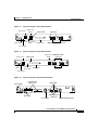
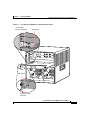
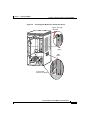
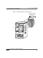
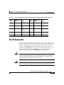
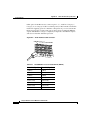
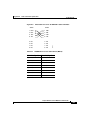
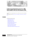
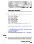
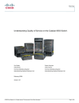
Figure 1-1 shows the front panel features of Supervisor Engine 1, Figure 1-2
shows the front panel features of Supervisor Engine 2, and Figure 1-3 shows the
front panel features of the Supervisor Engine 720.
Catalyst 6500 Series Switch Module Installation Guide
1-10
78-15725-02
Chapter 1
Product Overview
Supervisor Engines
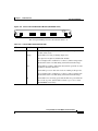
Figure 1-1
Supervisor Engine 1 Front Panel Features
Switch load
display
Console port
PCMCIA LED
LINK LEDs
WS-X6K-SUP1
16057
EJECT
LIN
PCMCIA
1%
PORT 2
K
PORT 1
K
CONSOLE
Load
LIN
G
M
ET
R
ES
R
S
U
TIV
ST
PW
AT
AC
SY
ST
E
EM
M
T
Switch
CONSOLE 100%
PORT
MODE
SUPERVISOR I
Console port mode
switch
PCMCIA slot
Status LEDs
1000BASE-X GBIC Uplink Ports
Reset button
Figure 1-2
Supervisor Engine 2 Front Panel Features
Console port
Switch load 1000BASE-X GBIC
display
Uplink Ports
PCMCIA LED
WS-X6K-SUP2-2GE
PCMCIA
EJECT
PORT 2
1%
Status
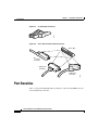
LEDs
LIN
K
SUPERVISOR2
Console port
mode switch
PCMCIA slot
44312
ET
ES
CONSOLE
LIN
K
LE
M
G
PORT 1
R
S
EM
U
SO
R
N
ST
PW
AT
O
C
SY
ST
Load
M
T
Switch
100%
CONSOLE
PORT
MODE
LINK LEDs
Reset button
Figure 1-3
CompactFlash
Type II slots
LINK LEDs
87890
Status LEDs
Supervisor Engine 720 Front Panel Features
Disk LEDs
Gigabit Ethernet
uplink port
Console port
10/100/1000 uplink port
Catalyst 6500 Series Switch Module Installation Guide
78-15725-02
1-11
Chapter 1
Product Overview
Supervisor Engines
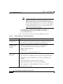
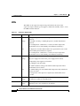
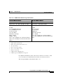
LEDs
The LEDs on the supervisor engine front panel indicate the status of the
supervisor engine, modules, power supplies, and the fan assembly. Table 1-3 lists
the LEDs and their function.
Table 1-3
Supervisor Engine LEDs
LED
Color/State Description
STATUS
Green
All diagnostics pass. The module is operational (normal initialization
sequence).
Orange
The module is booting or running diagnostics (normal initialization
sequence).
An overtemperature condition has occurred. (A minor temperature
threshold has been exceeded during environmental monitoring.)
Red
The diagnostic test failed. The module is not operational because a fault
occurred during the initialization sequence.
An overtemperature condition has occurred. (A major temperature
threshold has been exceeded during environmental monitoring.)
SYSTEM1
Green
All chassis environmental monitors are reporting OK.
Orange
The power supply has failed or the power supply fan has failed.
Incompatible power supplies are installed.
The redundant clock has failed.
One VTT2 module has failed or the VTT module temperature minor
threshold has been exceeded3.
Red
Two VTT modules fail or the VTT module temperature major threshold
has been exceeded3.
The temperature of the supervisor engine major threshold has been
exceeded.
ACTIVE
PWR
MGMT1
Green
The supervisor engine is operational and active.
Orange
The supervisor engine is in standby mode.
Green
Sufficient power is available for all modules.
Orange
Sufficient power is not available for all modules.
Catalyst 6500 Series Switch Module Installation Guide
1-12
78-15725-02
Chapter 1
Product Overview
Supervisor Engines
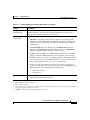
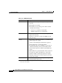
Table 1-3
LED
Supervisor Engine LEDs (continued)
Color/State Description
SWITCH
LOAD
If the switch is operational, the switch load meter indicates (as an
approximate percentage) the current traffic load over the backplane.
PCMCIA
The PCMCIA LED is lit when no Flash PC card is in the slot, and it goes
off when you insert a Flash PC card.
LINK
Green
The port is operational.
Orange
The link has been disabled by software.
Flashing
orange
The link is bad and has been disabled due to a hardware failure.
Off
No signal is detected.
1. The SYSTEM and PWR MGMT LED indications on a redundant supervisor engine are synchronized to the active supervisor
engine.
2. VTT = voltage termination module. The VTT module terminates signals on the Catalyst switching bus.
3. If no redundant supervisor engine is installed and there is a VTT module minor or major overtemperature condition, the
system shuts down.
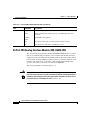
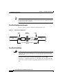
RESET Button
The RESET button allows you to restart the switch.
Note
Use a ballpoint pen tip or other small, pointed object to access the RESET button.
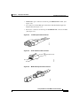
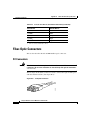
CONSOLE Port
The CONSOLE port allows you to access the switch either locally (with a console
terminal) or remotely (with a modem). The CONSOLE port is an EIA/TIA-232
asynchronous, serial connection with hardware flow control and an RJ-45
connector.
Catalyst 6500 Series Switch Module Installation Guide
78-15725-02
1-13
Chapter 1
Product Overview
Supervisor Engines
Note
EIA/TIA-232 and EIA/TIA-449 were known as recommended standards RS-232
and RS-449 before their acceptance as standards by the Electronic Industries
Alliance (EIA) and Telecommunications Industry Association (TIA).
For detailed information on using this port, see the “Connecting to the Console
Port—Supervisor Engine Only” section on page 3-15.
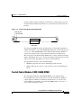
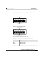
CONSOLE PORT MODE Switch
The CONSOLE PORT MODE switch allows you to connect a terminal to the
supervisor engine using either a Catalyst 5000 family Supervisor Engine III
console cable or the console cable and adapters provided with the Catalyst 6000
series or Catalyst 6500 series switch.
Note
The cable and adapters shipped with the switch are the same ones used on the
Cisco 2500 series routers (and other Cisco products).
Additionally, you can connect a modem to the console port using the cable and
adapter provided with the switch.
Note
Use a ballpoint pen tip or other small, pointed object to access the CONSOLE
PORT MODE switch.
Use the CONSOLE PORT MODE switch as follows:
•
Mode 1—Place the switch in the in position (factory default) to connect a
terminal to the console port using the console cable and data terminal
equipment (DTE) adapter (labeled “Terminal”) that shipped with the switch.
You can also use this mode to connect a modem to the console port using the
console cable and data communications equipment (DCE) adapter (labeled
“Modem”) that shipped with the switch.
•
Mode 2—Place the switch in the out position to connect a terminal to the
console port using the Catalyst 5000 family Supervisor Engine III console
cable (not provided).
Catalyst 6500 Series Switch Module Installation Guide
1-14
78-15725-02
Chapter 1
Product Overview
Supervisor Engines
For more information on using the console port, see the “Connecting to the
Console Port—Supervisor Engine Only” section on page 3-15.
Switch Load
The switch load meter provides you with a visual approximation of the current
traffic load across the backplane.
PCMCIA Slot
The Flash PC card (PCMCIA) slot holds a Flash PC card for additional Flash
memory. You can use this Flash memory to store and run software images or to
serve as an I/O device.
Note
Throughout this publication, the term Flash PC card is used in place of the term
PCMCIA card.
For detailed information on using the Flash PC card, see the “Using Flash PC
Cards” section on page 3-17.
The Supervisor Engine 720 has two PCMCIA slots. The slot labeled DISK 0
supports a CompactFlash card only. CompactFlash cards are available in 64 MB,
128 MB, and 256 MB capacities. The slot labeled DISK 1 supports either a
CompactFlash card or a 1-GB MicroDrive.
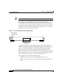
Uplink Ports
The supervisor engine provides two Gigabit Ethernet ports that you can configure
with any combination of copper, short-wave (SX), long-wave/long-haul (LX/LH),
extended-reach (ZX), and CWDM Gigabit Interface Converters (GBICs). The two
1000BASE-X Gigabit Ethernet ports operate in full-duplex mode only.
Note
In a redundant configuration with two supervisor engines, the uplink ports on the
redundant (standby) supervisor engine are active and can be used for normal
traffic like any other ports in the chassis.
Catalyst 6500 Series Switch Module Installation Guide
78-15725-02
1-15
Chapter 1
Product Overview
10/100 and 10/100/1000 Ethernet Switching Modules
For detailed information on these ports, see the “Connecting to the Uplink
Ports—Supervisor Engine Only” section on page 3-16.
The Supervisor Engine 720 has two uplink ports. The port labeled PORT 1
requires that a Small Form-Factor Pluggable (SFP) module be installed into it.
The port operates at 1 Gbps. The port labeled PORT 2 has two connectors: either
an SFP 1-Gbps port connector or a 10/100/1000BASE-T RJ-45 connector.
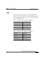
10/100 and 10/100/1000 Ethernet Switching Modules
Note
In this chapter, the term Catalyst 6500 series modules refers to modules that can
be installed in either the Catalyst 6000 series switch chassis (Catalyst 6006 and
Catalyst 6009 switches) or the Catalyst 6500 series switch chassis (Catalyst 6503,
Catalyst 6506, Catalyst 6509, Catalyst 6509-NEB, and Catalyst 6513 switches)
unless specifically noted.
Note
Specific combinations of supervisor engines and modules may not be supported
in your chassis. Refer to the release notes for the software version running on your
system for specific information on modules and supervisor engine combinations
that are not supported.
This section describes these Catalyst 6500 series 10/100 and 10/100/1000
Ethernet switching modules:
•
24-Port 10BASE-FL Ethernet Switching Module (WS-X6024-10FL-MT),
page 1-20
•
48-Port 10/100/1000BASE-T Ethernet Switching Module
(WS-X6148-GE-TX), page 1-21
•
48-Port 10/100/1000BASE-T Ethernet Switching Module
(WS-X6148V-GE-TX), page 1-21
•
48-Port 10/100BASE-T Ethernet Switching Module (WS-X6148-RJ21V),
page 1-22
•
48-Port 10/100BASE-T Ethernet Switching Module (WS-X6148-RJ45V),
page 1-23
Catalyst 6500 Series Switch Module Installation Guide
1-16
78-15725-02
Chapter 1
Product Overview
10/100 and 10/100/1000 Ethernet Switching Modules
•
24-Port 100BASE-FX Ethernet Switching Module (WS-X6224-100FX-MT),
page 1-24
•
48-Port 10/100BASE-T Ethernet Switching Module (WS-X6248-RJ45),
page 1-25
•
48-Port 10/100BASE-T Ethernet Switching Module (WS-X6248-TEL),
page 1-25
•
48-Port 10/100BASE-T Ethernet Switching Module (WS-X6248A-TEL),
page 1-26
•
24-Port 100BASE-FX Ethernet Switching Module
(WS-X6324-100FX-MM), page 1-26
•
24-Port 100BASE-FX Ethernet Switching Module (WS-X6324-100FX-SM),
page 1-27
•
48-Port 10/100BASE-T Ethernet Switching Module (WS-X6348-RJ21V),
page 1-28
•
48-Port 10/100BASE-T Ethernet Switching Module (WS-X6348-RJ-45),
page 1-29
•
48-Port 10/100BASE-T Ethernet Switching Module (WS-X6348-RJ45V),
page 1-30
•
24-Port 100BASE-FX Fabric-Enabled Ethernet Switching Module
(WS-X6524-100FX-MM), page 1-31
•
48-Port 10/100/1000BASE-T Ethernet Switching Module
(WS-X6548-GE-TX), page 1-31
•
48-Port 10/100/1000BASE-T Ethernet Switching Module
(WS-X6548V-GE-TX), page 1-32
•
48-Port 10/100BASE-T Fabric-Enabled Ethernet Switching Module
(WS-X6548-RJ-21), page 1-33
•
48-Port 10/100BASE-T Fabric-Enabled Ethernet Switching Module
(WS-X6548-RJ-45), page 1-34
•
48-Port 10/100/1000BASE-T Fabric-Enabled Ethernet Switching Module
(WS-X6748-GE-TX), page 1-35
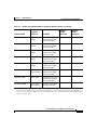
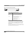
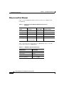
Table 1-4 lists the features of the Ethernet switching modules.
Catalyst 6500 Series Switch Module Installation Guide
78-15725-02
1-17
Chapter 1
Product Overview
10/100 and 10/100/1000 Ethernet Switching Modules
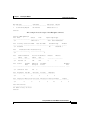
Table 1-4
Ethernet Switching Modules Features
Product Number
Backplane
Connection
Forwarding
Inline
Power1
Port Buffer
Size
Queues Per
Port
WS-X6024-10FL-MT
32 Gbps Bus
Centralized
No
128 KB
2 transmit,
1 receive
WS-X6148-GE-TX
32 Gbps Bus
Centralized
Optional2 128 KB
2 transmit,
1 receive
WS-6148V-GE-TX
32 Gbps Bus
Centralized
Yes
128 KB
2 transmit,
1 receive
WS-X6148-RJ21V
32 Gbps Bus
Centralized
Yes
128 KB
2 transmit,
1 receive
WS-X6148-RJ45V
32 Gbps Bus
Centralized
Yes
128 KB
2 transmit,
1 receive
WS-X6224-100FX-MT
32 Gbps Bus
Centralized
Yes
128 KB
2 transmit,
1 receive
WS-X6248-RJ-45
32 Gbps Bus
Centralized
No
128 KB
2 transmit,
1 receive
WS-X6248-TEL
32 Gbps Bus
Centralized
No
128 KB
2 transmit,
1 receive
WS-X6248A-TEL
32 Gbps Bus
Centralized
No
128 KB
2 transmit,
1 receive
WS-X6324-100FX-MM
32 Gbps Bus
Centralized
No
128 KB
2 transmit,
1 receive
WS-X6324-100FX-SM
32 Gbps Bus
Centralized
No
128 KB
2 transmit,
1 receive
WS-X6348-RJ21V
32 Gbps Bus
Centralized
Yes
128 KB
2 transmit,
1 receive
WS-X6348-RJ-45
32 Gbps Bus
Centralized
Optional 2 128 KB
2 transmit,
1 receive
WS-X6348-RJ45V
32 Gbps Bus
Centralized
Yes
2 transmit,
1 receive
128 KB
Catalyst 6500 Series Switch Module Installation Guide
1-18
78-15725-02
Chapter 1
Product Overview
10/100 and 10/100/1000 Ethernet Switching Modules
Table 1-4
Ethernet Switching Modules Features (continued)
Forwarding
Inline
Power1
Port Buffer
Size
Queues Per
Port
Switch Fabric
and Bus
Centralized
No
1 MB
4 transmit,
2 receive
WS-X6548-GE-TX
Switch Fabric
and Bus
Centralized
Optional2 1 MB
4 transmit,
2 receive
WS-6548V-GE-TX
Switch Fabric
and Bus
Centralized
Yes
1 MB
4 transmit,
2 receive
WS-X6548-RJ-21
Switch Fabric
and Bus
Centralized
No
1 MB
4 transmit,
2 receive
Switch Fabric
and Bus
Centralized
No
1 MB
4 transmit,
2 receive
Switch Fabric
CEF720
No
1.3 MB
4 transmit,
2 receive
Product Number
WS-X6524-100FX-MM
WS-X6548-RJ-45
WS-X6748-GE-TX
Backplane
Connection
Supports
optional DFC
card
Supports
optional DFC
card
Supports
optional DFC
card
1. Supports IP phones.
2. Supports an optional inline power field upgrade module (WS-F6K-VPWR=)
Catalyst 6500 Series Switch Module Installation Guide
78-15725-02
1-19
Chapter 1
Product Overview
10/100 and 10/100/1000 Ethernet Switching Modules
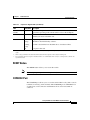
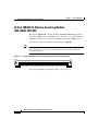
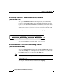
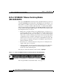
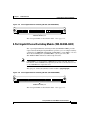
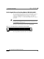
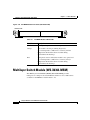
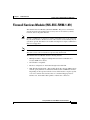
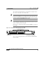
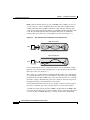
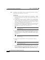
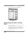
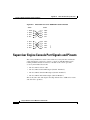
24-Port 10BASE-FL Ethernet Switching Module
(WS-X6024-10FL-MT)
The 24-port 10BASE-FL switching module (WS-X6024-10FL-MT) provides 24
switched, 10-Mbps, full- or half-duplex ports. (See Figure 1-4.) The module has
24 MT-RJ connectors for connection to multimode fiber-optic (MMF) cable.
The QoS port architecture (Rx/Tx) for this module is 1q4t/2q2t.
This module is a Class 1 laser product. Refer to the Regulatory Compliance and
Safety Information for the Catalyst 6500 Series Switches for information on
working with lasers.
Note
Figure 1-4
24-Port 10BASE-FL Ethernet Switching Module (WS-X6024-10FL-MT)
26947
LIN
K
LIN
K
LIN
K
LIN
K
LIN
K
LIN
K
LIN
K
LIN
K
LIN
K
LIN
K
LIN
K
LIN
K
LIN
K
LIN
K
LIN
K
LIN
K
LIN
K
LIN
K
LIN
K
LIN
K
LIN
K
LIN
K
LIN
K
24 PORT 10FL
LIN
K
ST
AT
US
WS-X6024-10FL-MT
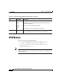
The front panel LEDs are described in Table 1-6 on page 1-47.
Catalyst 6500 Series Switch Module Installation Guide
1-20
78-15725-02
Chapter 1
Product Overview
10/100 and 10/100/1000 Ethernet Switching Modules
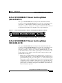
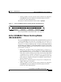
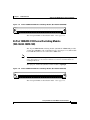
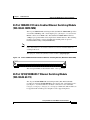
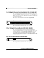
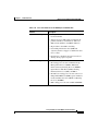
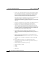
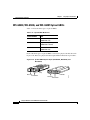
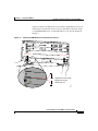
48-Port 10/100/1000BASE-T Ethernet Switching Module
(WS-X6148-GE-TX)
The 48-port 10/100/1000BASE-T switching module (WS-X6148-GE-TX)
provides 48 switched, 10/100/1000-Mbps autosensing, full- or half-duplex ports.
(See Figure 1-5.) The module has 48 RJ-45 connectors for use with either
Category 3, Category 5, Category 5e, or Category 6 UTP cable. This module can
be upgraded with an inline-power daughter card to support IP phones.
48-Port 10/100/1000BASE-T Ethernet Switching Module (WS-X6148-GE-TX)
47
48
48
47
46
45
44
43
42
41
40
39
38
37
36
35
34
33
32
PHONE
90851
37
38
SWITCHING MODULE
31
10/100/1000
BASE-T GE
35
36
30
24
23
22
21
20
19
18
17
16
15
14
13
9
12
8
11
7
10
6
5
4
3
2
1
48 PORT
25
26
29
23
24
28
STATUS
13
14
27
11
12
2
26
WS-X6148V-GE-TX 1
25
Figure 1-5
The front panel LEDs are described in Table 1-6 on page 1-47.
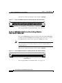
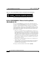
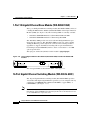
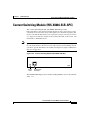
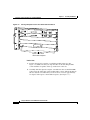
48-Port 10/100/1000BASE-T Ethernet Switching Module
(WS-X6148V-GE-TX)
The 48-port 10/100/1000BASE-T switching module (WS-X6148V-GE-TX)
provides 48 switched, 10/100/1000-Mbps autosensing, full- or half-duplex ports.
(See Figure 1-6.) The module has 48 RJ-45 connectors for use with either
Category 3, Category 5, Category 5e, or Category 6 UTP cable. The “V” in the
product number indicates that the inline-power daughter card is installed on the
module. With the voice daughter card installed, the module provides these IP
phone features on each port:
•
Inline power—Provides 48 VDC over standard Category 5, Category 5e, or
Category 6 UTP cable up to 328 feet (100 meters) from the switch to the IP
phone. With inline power, pairs 2 and 3 (pins 1, 2, 3, and 6) of the four pairs
in the cable are used to transmit power (6.3 W) from the switch. This method
of supplying power is sometimes called phantom power because the power
signals travel over the same two pairs used to transmit Ethernet signals. The
power signals are completely transparent to the Ethernet signals and do not
interfere with their operation.
Catalyst 6500 Series Switch Module Installation Guide
78-15725-02
1-21
Chapter 1
Product Overview
10/100 and 10/100/1000 Ethernet Switching Modules
•
Phone discovery—Automatically detects the presence of an IP phone and
supplies inline power to the phone.
•
Auxiliary VLANs—Provides automatic VLAN configuration for IP phones
using IEEE 802.1Q as the standards-based VLAN tagging mechanism
between the switch and the IP phone.
The QoS port architecture (Rx/Tx) for this module is 1q4t/2q2t.
48-Port 10/100/1000BASE-T Ethernet Switching Module (WS-X6148V-GE-TX)
47
48
48
47
46
45
44
43
42
41
40
39
38
37
36
35
34
33
32
PHONE
90851
37
38
SWITCHING MODULE
31
10/100/1000
BASE-T GE
35
36
30
24
23
22
21
20
19
18
17
16
15
14
13
12
9
8
11
7
10
6
5
4
3
2
1
48 PORT
25
26
29
23
24
28
STATUS
13
14
27
11
12
2
26
WS-X6148V-GE-TX 1
25
Figure 1-6
The front panel LEDs are described in Table 1-6 on page 1-47.
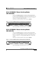
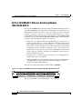
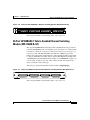
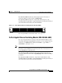
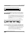
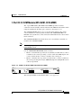
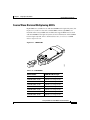
48-Port 10/100BASE-T Ethernet Switching Module
(WS-X6148-RJ21V)
The 48-port 10/100BASE-T switching module (WS-X6148-RJ21V) provides 48
switched, 10/100-Mbps autosensing, full- or half-duplex ports. (See Figure 1-7.)
The module has 4 RJ-21 connectors (12 ports per connector) for use with either
Category 3, Category 5, Category 5e, or Category 6 UTP cable. The “V” in the
product number indicates that the inline-power daughter card (WS-F6K-VPWR)
is installed on the module. With the WS-F6K-VPWR daughter card installed, the
module provides these IP phone features on each port:
•
Inline power—Provides 48 VDC over standard Category 5, Category 5e, or
Category 6 UTP cable up to 328 feet (100 meters) from the switch to the IP
phone. With inline power, pairs 2 and 3 (pins 1, 2, 3, and 6) of the four pairs
in the cable are used to transmit power (6.3 W) from the switch. This method
of supplying power is sometimes called phantom power because the power
signals travel over the same two pairs used to transmit Ethernet signals. The
power signals are completely transparent to the Ethernet signals and do not
interfere with their operation.
•
Phone discovery—Automatically detects the presence of an IP phone and
supplies inline power to the phone.
Catalyst 6500 Series Switch Module Installation Guide
1-22
78-15725-02
Chapter 1
Product Overview
10/100 and 10/100/1000 Ethernet Switching Modules
Auxiliary VLANs—Provides automatic VLAN configuration for IP phones
using IEEE 802.1Q as the standards-based VLAN tagging mechanism
between the switch and the IP phone.
•
The QoS port architecture (Rx/Tx) for this module is 1q4t/2q2t.
Figure 1-7
48-Port 10/100BASE-T Ethernet Switching Module (WS-X6148-RJ21V)
8
10/100 BASE-T
ETHERNET
SWITCHING MODULE
48
47
46
45
44
43
42
41
40
39
38
PHONE
37
36
35
34
33
32
31
30
29
28
27
26
25
24
23
22
21
20
19
18
17
16
15
14
13
9
12
8
11
7
10
6
5
4
3
2
1
STATUS
68149
37
-4
6
-3
25
48 PORT
1-
13
12
-2
4
WS-X6348-RJ21
The front panel LEDs are described in Table 1-6 on page 1-47.
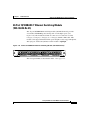
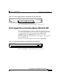
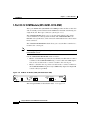
48-Port 10/100BASE-T Ethernet Switching Module
(WS-X6148-RJ45V)
The 48-port 10/100BASE-T switching module (WS-X6148-RJ45V) provides 48
switched, 10/100-Mbps autosensing, full- or half-duplex ports. (See Figure 1-8.)
The module has 48 RJ-45 connectors for use with either Category 3, Category 5,
Category 5e, or Category 6 UTP cable. The “V” in the product number indicates
that the inline-power daughter card (WS-F6K-VPWR) is installed on the module.
With the WS-F6K-VPWR daughter card installed, the module provides these IP
phone features on each port:
•
Inline power—Provides 48 VDC over standard Category 5, Category 5e, or
Category 6 UTP cable up to 328 feet (100 meters) from the switch to the IP
phone. With inline power, pairs 2 and 3 (pins 1, 2, 3, and 6) of the four pairs
in the cable are used to transmit power (6.3 W) from the switch. This method
of supplying power is sometimes called phantom power because the power
signals travel over the same two pairs used to transmit Ethernet signals. The
power signals are completely transparent to the Ethernet signals and do not
interfere with their operation.
•
Phone discovery—Automatically detects the presence of an IP phone and
supplies inline power to the phone.
•
Auxiliary VLANs—Provides automatic VLAN configuration for IP phones
using IEEE 802.1Q as the standards-based VLAN tagging mechanism
between the switch and the IP phone.
Catalyst 6500 Series Switch Module Installation Guide
78-15725-02
1-23
Chapter 1
Product Overview
10/100 and 10/100/1000 Ethernet Switching Modules
The QoS port architecture (Rx/Tx) for this module is 1q4t/2q2t.
Figure 1-8
48-Port 10/100BASE-T Ethernet Switching Module (WS-X6148-RJ45V)
39334
47
48
48
47
46
45
44
43
42
41
40
39
38
37
36
35
34
33
32
31
30
29
28
27
26
PHONE
25
ETHERNET SWITCHING
MODULE
37
38
35
36
25
26
23
24
24
23
22
21
20
19
18
17
15
16
13
14
48 PORT
10/100 BASE-T
14
9
12
8
11
7
10
6
5
4
3
2
1
STATUS
13
2
1
11
12
WS-X6348-RJ-45V
The front panel LEDs are described in Table 1-6 on page 1-47.
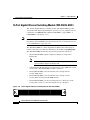
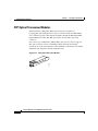
24-Port 100BASE-FX Ethernet Switching Module
(WS-X6224-100FX-MT)
The 24-port 100BASE-FX Etherent switching module (WS-X6224-100FX-MT)
provides 24 switched, 100-Mbps, full or half-duplex ports. (See Figure 1-9.) Ports
have MT-RJ optical connectors for connection to MMF optical cable.
This module is a Class 1 laser product. Refer to the Regulatory Compliance and
Safety Information for the Catalyst 6500 Series Switches for information on
working with lasers.
Note
The QoS port architecture (Rx/Tx) for this module is 1q4t/2q2t.
Figure 1-9
24-Port 100BASE-FX Ethernet Switching Module (WS-X6224-100FX-MT)
2
3
4
5
6
7
8
9
10
11
12
13
14
15
16
17
18
19
20
21
22
23
24
K
N
LI
K
N
LI
K
N
LI
K
K
N
N
LI
LI
K
N
LI
K
N
LI
K
N
LI
K
N
LI
K
N
LI
K
K
N
N
LI
LI
K
N
LI
K
N
LI
K
N
LI
K
N
K
N
LI
LI
K
N
LI
K
N
LI
K
N
LI
K
N
LI
K
K
N
N
LI
LI
K
N
LI
24 PORT 100FX
16063
1
ST
AT
US
WS-X6224
100BASE-FX ports
The front panel LEDs are described in Table 1-6 on page 1-47.
Catalyst 6500 Series Switch Module Installation Guide
1-24
78-15725-02
Chapter 1
Product Overview
10/100 and 10/100/1000 Ethernet Switching Modules
48-Port 10/100BASE-T Ethernet Switching Module
(WS-X6248-RJ45)
The 48-port 10/100BASE-T Ethernet switching module (WS-X6248-RJ45)
provides 48 switched 10/100-Mbps autosensing, full or half-duplex ports. (See
Figure 1-10.) The 48 ports have RJ-45 connectors for Category 3, Category 5,
Category 5e, or Category 6 UTP or FTP cable.
The QoS port architecture (Rx/Tx) for this module is 1q4t/2q2t.
Figure 1-10 48-Port 10/100BASE-TX Ethernet Switching Module (WS-X6248-RJ45)
16791
48
47
46
45
44
43
42
41
40
39
38
37
48
38
36
35
34
33
32
31
30
29
28
27
26
36
26
ETHERNET SWITCHING
MODULE
25
24
23
22
21
20
19
18
17
16
15
14
24
14
48 PORT
10/100 BASE-T
13
9
12
8
11
7
10
6
5
4
3
2
1
2
12
1
WS-X6248-RJ-45
The front panel LEDs are described in Table 1-6 on page 1-47.
48-Port 10/100BASE-T Ethernet Switching Module
(WS-X6248-TEL)
The 48-port 10/100BASE-T Ethernet switching module (WS-X6248-TEL)
provides 48 switched 10/100-Mbps autosensing, full or half-duplex ports. (See
Figure 1-11.) Four RJ-21 connectors (12 ports per connector) use Category 3,
Category 5, Category 5e, or Category 6 UTP or FTP cable to connect to the
network.
The QoS port architecture (Rx/Tx) for this module is 1q4t/2q2t.
Figure 1-11 48-Port 10/100BASE-T Ethernet Switching Module (WS-X6248-TEL)
8
-4
6
18502
48
47
46
45
44
43
42
41
40
39
38
37
37
36
35
34
33
32
31
30
29
28
27
26
25
24
23
22
21
20
19
18
17
16
15
ETHERNET SWITCHING
MODULE
14
48 PORT
10/100 BASE-T
13
25
-3
-2
13
12
11
10
9
8
7
6
5
4
3
2
1
1-
12
4
WS-X6248-RJ-TEL
The front panel LEDs are described in Table 1-6 on page 1-47.
Catalyst 6500 Series Switch Module Installation Guide
78-15725-02
1-25
Chapter 1
Product Overview
10/100 and 10/100/1000 Ethernet Switching Modules
48-Port 10/100BASE-T Ethernet Switching Module
(WS-X6248A-TEL)
The 48-port 10/100BASE-T Ethernet switching module (WS-X6248A-TEL)
provides 48 switched 10/100-Mbps autosensing, full or half-duplex ports. (See
Figure 1-12.) The WS-X6248A-TEL Ethernet module has a larger buffer than the
WS-X6248-TEL Ethernet module. Four RJ-21 connectors (12 ports per
connector) use Category 3, Category 5, Category 5e, or Category 6 UTP or FTP
cable to connect to the network.
The QoS port architecture (Rx/Tx) for this module is 1q4t/2q2t.
Figure 1-12 48-Port 10/100BASE-T Ethernet Switching Module (WS-X6248A-TEL)
8
18502
48
47
46
45
44
43
42
41
40
39
38
37
36
35
34
33
32
31
30
29
28
27
26
25
37
-4
6
-3
25
24
23
22
21
20
19
18
17
16
15
ETHERNET SWITCHING
MODULE
14
48 PORT
10/100 BASE-T
13
13
9
12
8
11
7
10
6
5
4
3
2
1
1-
12
-2
4
WS-X6248-RJ-TEL
The front panel LEDs are described in Table 1-6 on page 1-47.
24-Port 100BASE-FX Ethernet Switching Module
(WS-X6324-100FX-MM)
The 24-port 100BASE-FX switching module (WS-X6324-100FX-MM) provides
24 switched, 100-Mbps, full- or half-duplex ports. (See Figure 1-13.) The module
has 24 MT-RJ connectors for connection to the MMF cable.
Note
This module is a Class 1 laser product. Refer to the Regulatory Compliance and
Safety Information for the Catalyst 6500 Series Switches for information on
working with lasers.
The QoS port architecture (Rx/Tx) for this module is 1q4t/2q2t.
Catalyst 6500 Series Switch Module Installation Guide
1-26
78-15725-02
Chapter 1
Product Overview
10/100 and 10/100/1000 Ethernet Switching Modules
Figure 1-13 24-Port 100BASE-FX Ethernet Switching Module (WS-X6324-100FX-MM)
2
3
4
5
6
7
8
9
10
11
12
13
14
15
16
17
18
19
20
21
22
23
24
N
K
N
K
LI
N
K
LI
N
K
LI
N
K
LI
N
K
LI
N
K
LI
N
K
LI
N
K
LI
N
K
LI
N
K
LI
N
K
LI
N
K
LI
LI
N
K
N
K
LI
N
K
LI
N
K
LI
N
K
LI
LI
N
K
N
K
LI
N
K
LI
N
K
LI
N
K
LI
LI
LI
N
K
24 PORT 100FX-MMF
44744
1
ST
AT
US
WS-X6324-100FX-MM
The front panel LEDs are described in Table 1-6 on page 1-47.
24-Port 100BASE-FX Ethernet Switching Module
(WS-X6324-100FX-SM)
The 24-port 100BASE-FX switching module (WS-X6324-100FX-SM) provides
24 switched, 100-Mbps, full- or half-duplex ports. (See Figure 1-14.) The module
has 24 MT-RJ connectors for connection to SMF cable.
This module is a Class 1 laser product. Refer to the Regulatory Compliance and
Safety Information for the Catalyst 6500 Series Switches for information on
working with lasers.
Note
The QoS port architecture (Rx/Tx) for this module is 1q4t/2q2t.
Figure 1-14 24-Port 100BASE-FX Ethernet Switching Module (WS-X6324-100FX-SM)
2
3
4
5
6
7
8
9
10
11
12
13
14
15
16
17
18
19
20
21
22
23
24
K
N
LI
K
K
N
N
LI
K
K
N
LI
LI
K
N
LI
K
N
LI
N
LI
K
N
LI
K
K
N
N
LI
K
K
N
LI
LI
K
N
N
LI
LI
K
N
LI
K
N
LI
K
K
N
K
N
LI
LI
K
N
LI
K
N
LI
N
LI
K
N
LI
K
N
LI
K
N
LI
K
N
LI
24 PORT 100FX-SMF
44745
1
ST
AT
US
WS-X6324-100FX-SM
The front panel LEDs are described in Table 1-6 on page 1-47.
Catalyst 6500 Series Switch Module Installation Guide
78-15725-02
1-27
Chapter 1
Product Overview
10/100 and 10/100/1000 Ethernet Switching Modules
48-Port 10/100BASE-T Ethernet Switching Module
(WS-X6348-RJ21V)
The 48-port 10/100BASE-T switching module (WS-X6148-RJ21V) provides 48
switched, 10/100-Mbps autosensing, full- or half-duplex ports. (See Figure 1-15.)
The module has 4 RJ-21 connectors (12 ports per connector) for use with either
Category 3, Category 5, Category 5e, or Category 6 UTP cable. The “V” in the
product number indicates that the inline-power daughter card (WS-F6K-VPWR)
is installed on the module. With the WS-F6K-VPWR daughter card installed, the
module provides these IP phone features on each port:
•
Inline power—Provides 48 VDC over standard Category 5, Category 5e, or
Category 6 UTP cable up to 328 feet (100 meters) from the switch to the IP
phone. With inline power, pairs 2 and 3 (pins 1, 2, 3, and 6) of the four pairs
in the cable are used to transmit power (6.3 W) from the switch. This method
of supplying power is sometimes called phantom power because the power
signals travel over the same two pairs used to transmit Ethernet signals. The
power signals are completely transparent to the Ethernet signals and do not
interfere with their operation.
•
Phone discovery—Automatically detects the presence of an IP phone and
supplies inline power to the phone.
•
Auxiliary VLANs—Provides automatic VLAN configuration for IP phones
using IEEE 802.1Q as the standards-based VLAN tagging mechanism
between the switch and the IP phone.
The QoS port architecture (Rx/Tx) for this module is 1q4t/2q2t.
Figure 1-15 48-Port 10/100BASE-T Ethernet Switching Module (WS-X6348-RJ-21V)
8
48 PORT
10/100 BASE-T
ETHERNET
SWITCHING MODULE
48
47
46
45
44
43
42
41
40
39
38
PHONE
37
36
35
34
33
32
31
30
29
28
27
26
25
24
23
22
21
20
19
18
17
16
15
14
13
9
12
8
11
7
10
6
5
4
3
2
1
STATUS
68149
37
-4
6
-3
25
-2
13
1-
12
4
WS-X6348-RJ21
The front panel LEDs are described in Table 1-6 on page 1-47.
Catalyst 6500 Series Switch Module Installation Guide
1-28
78-15725-02
Chapter 1
Product Overview
10/100 and 10/100/1000 Ethernet Switching Modules
48-Port 10/100BASE-T Ethernet Switching Module
(WS-X6348-RJ-45)
The 48-port 10/100BASE-T switching module (WS-X6348-RJ-45) provides
48 switched, 10/100-Mbps autosensing, full- or half-duplex ports. (See
Figure 1-16.) The module has 48 RJ-45 connectors for connection to either
Category 3, Category 5, Category 5e, or Category 6 UTP or FTP cable. This
module can be upgraded with an inline-power daughter card to support IP phones.
The QoS port architecture (Rx/Tx) for this module is 1q4t/2q2t.
Figure 1-16 48-Port 10/100BASE-T Ethernet Switching Module (WS-X6348-RJ-45)
48
47
46
45
44
43
42
41
40
39
38
37
36
35
34
33
32
31
30
29
28
27
PHONE
26
ETHERNET SWITCHING
MODULE
25
24
23
22
21
20
19
18
17
16
15
14
48 PORT
10/100 BASE-T
13
9
12
8
11
7
10
6
5
4
3
2
1
STATUS
39496
48
36
38
26
24
12
2
14
1
WS-X6348-RJ-45
The front panel LEDs are described in Table 1-6 on page 1-47.
Catalyst 6500 Series Switch Module Installation Guide
78-15725-02
1-29
Chapter 1
Product Overview
10/100 and 10/100/1000 Ethernet Switching Modules
48-Port 10/100BASE-T Ethernet Switching Module
(WS-X6348-RJ45V)
The 48-port 10/100BASE-T switching module (WS-X6348-RJ45V) provides 48
switched, 10/100-Mbps autosensing, full- or half-duplex ports. (See Figure 1-17.)
The module has 48 RJ-45 connectors for use with either Category 3, Category 5,
Category 5e, or Category 6 UTP or FTP cable. The “V” in the product number
indicates that the inline-power daughter card (WS-F6K-VPWR) is installed on the
module. With the WS-F6K-VPWR daughter card installed, the module provides
these IP phone features on each port:
•
Inline power—Provides 48 VDC over standard Category 5, Category 5e, or
Category 6 UTP cable up to 328 feet (100 meters) from the switch to the IP
phone. With inline power, pairs 2 and 3 (pins 1, 2, 3, and 6) of the four pairs
in the cable are used to transmit power (6.3 W) from the switch. This method
of supplying power is sometimes called phantom power because the power
signals travel over the same two pairs used to transmit Ethernet signals. The
power signals are completely transparent to the Ethernet signals and do not
interfere with their operation.
•
Phone discovery—Automatically detects the presence of an IP phone and
supplies inline power to the phone.
•
Auxiliary VLANs—Provides automatic VLAN configuration for IP phones
using IEEE 802.1Q as the standards-based VLAN tagging mechanism
between the switch and the IP phone.
The QoS port architecture (Rx/Tx) for this module is 1q4t/2q2t.
Figure 1-17 48-Port 10/100BASE-T Ethernet Switching Module (WS-X6348-RJ45V)
48
47
46
45
44
43
42
41
40
39
38
37
36
35
34
33
32
31
30
29
28
27
26
PHONE
39334
47
48
35
36
37
38
25
26
ETHERNET SWITCHING
MODULE
25
23
24
24
23
22
21
20
19
18
17
16
15
13
14
48 PORT
10/100 BASE-T
14
9
12
8
11
7
10
6
5
4
3
2
1
STATUS
13
2
1
11
12
WS-X6348-RJ-45V
The front panel LEDs are described in Table 1-6 on page 1-47.
Catalyst 6500 Series Switch Module Installation Guide
1-30
78-15725-02
Chapter 1
Product Overview
10/100 and 10/100/1000 Ethernet Switching Modules
24-Port 100BASE-FX Fabric-Enabled Ethernet Switching Module
(WS-X6524-100FX-MM)
The 24-port 100BASE-FX switching module (WS-X6524-100FX-MM) provides
24 switched, 100-Mbps, full- or half-duplex ports. (See Figure 1-18.) Ports have
MT-RJ connectors for MMF cable. The WS-X6524-100FX-MM module has
1-MB per-port packet buffers and a single fabric channel interface. The switching
module is upgradable to support distributed forwarding with an optional
Distributed Forwarding Card (WS-F6K-DFC).
This module is a Class 1 laser product. Refer to the Regulatory Compliance and
Safety Information for the Catalyst 6500 Series Switches for information on
working with lasers.
Note
The QoS port architecture (Rx/Tx) for this module is 1p1q0t/1p3q1t.
Figure 1-18 24-Port 100BASE-FX Fabric-Enabled Ethernet Switching Module (WS-X6524-100FX-MM)
K
K
N
LI
N
K
24
LI
N
K
23
LI
N
K
22
LI
N
K
21
LI
N
K
20
LI
N
K
19
LI
N
K
18
LI
N
K
17
LI
N
K
16
LI
N
K
15
LI
N
K
14
LI
N
K
13
LI
N
K
12
LI
N
K
11
LI
N
K
10
LI
N
K
9
LI
N
K
8
LI
N
K
7
LI
N
K
6
LI
N
K
5
LI
N
K
4
LI
K
3
N
N
LI
STATUS
2
LI
1
63671
WS-X6524-100FX-MM
24 PORT 100FX-MMF
The front panel LEDs are described in Table 1-6 on page 1-47.
48-Port 10/100/1000BASE-T Ethernet Switching Module
(WS-X6548-GE-TX)
The 48-port 10/100/1000BASE-T switching module (WS-X6548-GE-TX)
provides 48 switched, 10/100/1000-Mbps autosensing, full- or half-duplex ports.
(See Figure 1-19.) The module has 48 RJ-45 connectors for use with either
Category 3, Category 5, Category 5e, or Category 6 UTP cable. This module can
be upgraded with an inline-power daughter card to support IP phones.
Catalyst 6500 Series Switch Module Installation Guide
78-15725-02
1-31
Chapter 1
Product Overview
10/100 and 10/100/1000 Ethernet Switching Modules
Figure 1-19 48-Port 10/100/1000BASE-T Ethernet Switching Module (WS_X6548-GE-TX)
47
48
48
47
46
45
44
43
42
41
40
39
38
37
36
35
34
33
32
31
PHONE
90852
37
38
SWITCHING MODULE
30
10/100/1000
BASE-T GE
35
36
29
24
22
21
20
23
19
18
17
16
15
14
9
12
8
11
7
10
6
5
4
3
2
1
48 PORT
25
26
28
23
24
27
STATUS
13
14
26
11
12
2
25
1
13
WS-X6148-GE-TX
The front panel LEDs are described in Table 1-6 on page 1-47.
48-Port 10/100/1000BASE-T Ethernet Switching Module
(WS-X6548V-GE-TX)
The 48-port 10/100/1000BASE-T switching module (WS-X6548V-GE-TX)
provides 48 switched, 10/100/1000-Mbps autosensing, full- or half-duplex ports.
(See Figure 1-20.) The module has 48 RJ-45 connectors for use with either
Category 3, Category 5, Category 5e, or Category 6 UTP cable. The “V” in the
product number indicates that the inline-power daughter card is installed on the
module. With the voice daughter card installed, the module provides these IP
phone features on each port:
•
Inline power—Provides 48 VDC over standard Category 5, Category 5e, or
Category 6 UTP cable up to 328 feet (100 meters) from the switch to the IP
phone. With inline power, pairs 2 and 3 (pins 1, 2, 3, and 6) of the four pairs
in the cable are used to transmit power (6.3 W) from the switch. This method
of supplying power is sometimes called phantom power because the power
signals travel over the same two pairs used to transmit Ethernet signals. The
power signals are completely transparent to the Ethernet signals and do not
interfere with their operation.
•
Phone discovery—Automatically detects the presence of an IP phone and
supplies inline power to the phone.
•
Auxiliary VLANs—Provides automatic VLAN configuration for IP phones
using IEEE 802.1Q as the standards-based VLAN tagging mechanism
between the switch and the IP phone.
The QoS port architecture (Rx/Tx) for this module is 1q4t/2q2t.
Catalyst 6500 Series Switch Module Installation Guide
1-32
78-15725-02
Chapter 1
Product Overview
10/100 and 10/100/1000 Ethernet Switching Modules
Figure 1-20 48-Port 10/100/1000BASE-T Ethernet Switching Module (WS-X6548V-GE-TX)
47
48
48
47
46
45
44
43
42
41
40
39
38
37
36
35
34
33
32
PHONE
90852
37
38
SWITCHING MODULE
31
10/100/1000
BASE-T GE
35
36
30
24
23
22
21
20
19
18
17
16
15
14
13
12
9
11
8
10
7
6
5
4
3
2
1
48 PORT
25
26
29
23
24
28
STATUS
13
14
27
11
12
2
26
1
25
WS-X6148-GE-TX
The front panel LEDs are described in Table 1-6 on page 1-47.
48-Port 10/100BASE-T Fabric-Enabled Ethernet Switching
Module (WS-X6548-RJ-21)
The 48-port 10/100BASE-T switching module (WS-X6548-RJ-21) provides 48
switched, 10/100-Mbps, full- or half-duplex ports. (See Figure 1-21.) The module
has 4 RJ-21 connectors (12 ports per connector) for Category 5, Category 5e, or
Category 6 cable. The WS-X6548-RJ-21 module has 1-MB per-port packet
buffers and a single fabric channel interface. The switching module is upgradable
to support distributed forwarding with an optional Distributed Forwarding Card
(WS-F6K-DFC). The WS-X6548-RJ-21 module is auto-MDI/MDIX capable; you
can use either straight or crossover cable, and the module will automatically
detect and adjust for the cable type.
The QoS port architecture (Rx/Tx) for this module is 1p1q0t/1p3q1t.
Figure 1-21 48-Port 10/100BASE-T Fabric-Enabled Ethernet Switching Module (WS-X6548-RJ-21)
8
48 PORT
10/100 BASE-T
ETHERNET
SWITCHING MODULE
48
47
46
45
44
43
42
41
40
39
38
37
36
35
34
33
32
31
30
29
28
27
26
25
24
23
22
21
20
19
18
17
16
15
14
13
12
11
10
9
8
7
6
5
4
3
2
1
STATUS
63672
37
-4
6
-3
25
-2
13
1-
12
4
WS-X6548-RJ21
The front panel LEDs are described in Table 1-6 on page 1-47.
Catalyst 6500 Series Switch Module Installation Guide
78-15725-02
1-33
Chapter 1
Product Overview
10/100 and 10/100/1000 Ethernet Switching Modules
48-Port 10/100BASE-T Fabric-Enabled Ethernet Switching
Module (WS-X6548-RJ-45)
The 48-port 10/100BASE-T switching module (WS-X6548-RJ-45) provides
48 switched, 10/100-Mbps, full- or half-duplex ports. (See Figure 1-22.) Ports
have RJ-45 connectors for Category 5, 5e, and 6 cable. The WS-X6548-RJ-45
module has 1-MB per-port packet buffers and a single fabric channel interface.
The switching module is upgradable to support distributed forwarding with an
optional Distributed Forwarding Card (WS-F6K-DFC). The WS-X6548-RJ-45
module is auto-MDI/MDIX capable; you can use either straight or crossover
cable, and the module will automatically detect and adjust for the cable type.
The QoS port architecture (Rx/Tx) for this module is 1p1q0t/1p3q1t.
Figure 1-22 48-Port 10/100BASE-T Fabric-Enabled Ethernet Switching Module (WS-X6548-RJ-45)
47
46
45
44
43
42
41
40
39
38
37
36
35
34
33
32
31
63673
47
48
48
PH
O
N
E
37
38
SWITCHING MODULE
30
10/100 BASE-T
ETHERNET
35
36
29
24
23
22
21
20
19
18
17
16
15
14
9
12
8
11
7
10
6
5
4
3
2
1
48 PORT
25
26
28
23
24
27
STATUS
13
14
26
11
12
2
25
1
13
WS-X6548
The front panel LEDs are described in Table 1-6 on page 1-47.
Catalyst 6500 Series Switch Module Installation Guide
1-34
78-15725-02
Chapter 1
Product Overview
10/100 and 10/100/1000 Ethernet Switching Modules
48-Port 10/100/1000BASE-T Fabric-Enabled Ethernet Switching
Module (WS-X6748-GE-TX)
The 48-port 10/100/1000BASE-T switching module (WS-X6748-GE-TX)
provides 48 switched, 10/100/1000-Mbps, full- or half-duplex ports. (See
Figure 1-22.) Ports have RJ-45 connectors for Category 5, Category 5e, and
Category 6 cable. The WS-X6748-GE-TX module has 1.3-MB per-port packet
buffers and a dual-fabric channel interface. The switching module is upgradable
to support distributed forwarding with an optional Distributed Forwarding Card
(WS-F6K-DFC3).
The QoS port architecture (Rx/Tx) for this module is 1q8t/1p3q8t.
Figure 1-23 48-Port 10/100/1000BASE-T Fabric-Enabled Ethernet Switching Module
(WS-X6748-GE-TX)
)
48 PORT 10/100/1000 RJ-45
13
14
23
24
25
26
35
36
37
38
47
48
47
46
45
44
43
42
41
40
39
36
35
34
33
32
31
30
29
28
27
26
25
24
23
22
21
20
19
18
17
16
15
14
13
9
12
8
11
7
10
6
5
4
3
2
1
38
SWITCHING MODULE
STATUS
99884
11
12
2
48
PH
O
N
E
1
37
WS-X6748-GE-TX
The front panel LEDs are described in Table 1-6 on page 1-47.
Catalyst 6500 Series Switch Module Installation Guide
78-15725-02
1-35
Chapter 1
Product Overview
Gigabit Ethernet Switching Modules
Gigabit Ethernet Switching Modules
This section describes these Gigabit Ethernet switching modules:
•
16-Port Gigabit Ethernet Switching Module (WS-X6316-GE-TX), page 1-38
•
8-Port Gigabit Ethernet Switching Module (WS-X6408-GBIC), page 1-38
•
8-Port Gigabit Ethernet Switching Module (WS-X6408A-GBIC), page 1-39
•
16-Port Gigabit Ethernet Switching Module (WS-X6416-GBIC), page 1-40
•
16-Port Gigabit Ethernet Switching Module (WS-X6416-GE-MT), page 1-41
•
1-Port 10-Gigabit Ethernet Module (WS-X6501-10GEX4), page 1-41
•
1-Port 10-Gigabit Ethernet Base Module (WS-X6502-10GE), page 1-42
•
16-Port Gigabit Ethernet Switching Module (WS-X6516-GBIC), page 1-42
•
16-Port Gigabit Ethernet Switching Module (WS-X6516A-GBIC), page 1-43
•
16-Port 10/100/1000BASE-T Gigabit Ethernet Switching Module
(WS-X6516-GE-TX), page 1-44
•
4-Port 10 Gigabit Ethernet Switching Module (WS-X6704-10GE), page 1-44
•
24-Port Gigabit Ethernet Switching Module (WS-X6724-SFP), page 1-45
•
16-Port Gigabit Ethernet Switching Module (WS-X6816-GBIC), page 1-46
For LED indicators, see the “Ethernet Module LEDs” section on page 1-47.
Table 1-5 summarizes some of the features of the Gigabit Ethernet switching
modules.
Table 1-5
Gigabit and 10-Gigabit Ethernet Switching Modules Features
Forwarding
Number of
Transmit
Queues/Port
Number of
Receive
Queues/Port
Bus
Centralized
3
2
WS-X6408-GBIC
Bus
Centralized
3
2
WS-X6408A-GBIC
Bus
Centralized
3
2
WS-X6416-GBIC
Bus
Centralized
3
2
WS-X6416-GE-MT
Bus
Centralized
3
2
Product Number
Backplane
Connection
WS-X6316-GE-TX
Catalyst 6500 Series Switch Module Installation Guide
1-36
78-15725-02
Chapter 1
Product Overview
Gigabit Ethernet Switching Modules
Table 1-5
Gigabit and 10-Gigabit Ethernet Switching Modules Features (continued)
Product Number
Backplane
Connection
Forwarding
Number of
Transmit
Queues/Port
Number of
Receive
Queues/Port
WS-X6501-10GEX4
Switch fabric
and bus
Centralized. Support for 3
distributed forwarding
with optional DFC1
2
WS-X6502 -10GE
Switch fabric
and bus
Centralized. Support for 3
distributed forwarding
with optional DFC1
2
WS-X6516-GBIC
Switch fabric
and bus
Centralized. Support for 3
distributed forwarding
with optional DFC1
2
WS-X6516A-GBIC
Switch fabric
and bus
Centralized. Support for 3
distributed forwarding
with optional DFC1
2
WS-X6516-GE-TX
Switch fabric
and bus
Centralized. Support for 3
distributed forwarding
with optional DFC1
2
WS-X6704-10GE
Switch fabric2
(dual channel)
Centralized. Support for 3
distributed forwarding
with optional DFC1
2
WS-X6724-SFP
Switch fabric
Centralized. Support for 3
distributed forwarding
with optional DFC1
2
WS-X6816-GBIC
Switch fabric2
(dual channel)
Distributed forwarding
with integrated DFC1
2
3
1. DFC = Distributed Forwarding Card
2. The module can be installed in slots 2–6 in the Catalyst 6506, slots 2–9 in the Catalyst 6509 and Catalyst 6509-NEB, and
slots 9–13 in the Catalyst 6513 switches. It cannot be installed in slots 2–8 of the Catalyst 6513 switch. The module requires
a Supervisor Engine 720.
Catalyst 6500 Series Switch Module Installation Guide
78-15725-02
1-37
Chapter 1
Product Overview
Gigabit Ethernet Switching Modules
These modules are Class 1 laser products. Refer to the Regulatory Compliance
and Safety Information for the Catalyst 6500 Series Switches for information on
working with lasers.
Note
16-Port Gigabit Ethernet Switching Module (WS-X6316-GE-TX)
The 16-port Gigabit Ethernet switching module (WS-X6316-GE-TX) provides 16
switched, full-duplex Gigabit Ethernet ports. (See Figure 1-24.) Ports have RJ-45
connectors for Category 5 UTP. The WS-X6316-GE-TX module has enhanced
QoS features.
The QoS port architecture (Rx/Tx) for this module is 1p1q4t/1p2q2t.
Figure 1-24 16-Port Gigabit Ethernet Switching Module (WS-X6316-GE-TX)
4
LIN
K
LIN
K
5
6
7
8
LIN
K
3
LIN
K
2
LIN
K
1
9
10
11
12
13
14
15
16
44314
LIN
K
LIN
K
LIN
K
LIN
K
LIN
K
LIN
K
LIN
K
LIN
K
LIN
K
LIN
K
16 PORT 1000 BASE-T GE
LIN
K
ST
AT
US
WS-X6316-GE-7X
The front panel LEDs are described in Table 1-6 on page 1-47.
8-Port Gigabit Ethernet Switching Module (WS-X6408-GBIC)
The 8-port Gigabit Ethernet switching module (WS-X6408-GBIC) provides eight
switched, full-duplex Gigabit Ethernet ports that you can configure with any
combination of 1000BASE-SX, LX/LH, and ZX GBICs, copper GBICs, or Coarse
Wave Division Multiplexer (CWDM) GBICs. (See Figure 1-25.)
Note
CWDM GBICs are used with the CWDM Passive Optical System. For more
information on the CWDM Passive Optical System, refer to the Installation Note
for the CWDM Passive Optical System.
The QoS port architecture (Rx/Tx) for this module is 1q4t/2q2t.
Catalyst 6500 Series Switch Module Installation Guide
1-38
78-15725-02
Chapter 1
Product Overview
Gigabit Ethernet Switching Modules
Figure 1-25 8-Port Gigabit Ethernet Switching Module (WS-X6408-GBIC)
2
3
4
5
6
7
8
N
K
LI
N
K
LI
N
K
LI
N
K
LI
N
K
LI
N
K
LI
LI
N
K
LI
N
K
ST
8 PORT GIGABIT ETHERNET
16061
1
AT
US
WS-X6408
1000BASE-X GBIC ports
The front panel LEDs are described in Table 1-6 on page 1-47.
8-Port Gigabit Ethernet Switching Module (WS-X6408A-GBIC)
The 8-port Gigabit Ethernet switching module (WS-X6408A-GBIC) provides
eight switched, full-duplex Gigabit Ethernet ports that you can configure with any
combination of 1000BASE-SX, LX/LH, and ZX GBICs, copper GBICs, or Coarse
Wave Division Multiplexer (CWDM) GBICs. (See Figure 1-26.) The
WS-X6408A-GBIC module has enhanced QoS features.
CWDM GBICs are used with the CWDM Passive Optical System. For more
information on the CWDM Passive Optical System, refer to the Installation Note
for the CWDM Passive Optical System.
Note
The QoS port architecture (Rx/Tx) for this module is 1p1q4t/1p2q2t.
Figure 1-26 8-Port Gigabit Ethernet Switching Module (WS-X6408A-GBIC)
2
3
4
5
6
7
8
K
N
LI
K
N
LI
K
N
LI
K
N
LI
K
N
LI
K
N
LI
K
N
LI
LI
N
K
ST
8 PORT GIGABIT ETHERNET
16061
1
AT
US
WS-X6408
1000BASE-X GBIC ports
The front panel LEDs are described in Table 1-6 on page 1-47.
Catalyst 6500 Series Switch Module Installation Guide
78-15725-02
1-39
Chapter 1
Product Overview
Gigabit Ethernet Switching Modules
16-Port Gigabit Ethernet Switching Module (WS-X6416-GBIC)
The 16-port Gigabit Ethernet switching module (WS-X6416-GBIC) provides 16
switched, full-duplex Gigabit Ethernet ports that you can configure with any
combination of 1000BASE-SX, LX/LH, and ZX GBICs, copper GBICs, or
CWDM GBICs. (See Figure 1-27.) The WS-X6416-GBIC module has enhanced
QoS features.
CWDM GBICs are used with the CWDM Passive Optical System. For more
information on the CWDM Passive Optical System, refer to the Installation Note
for the CWDM Passive Optical System.
Note
The QoS port architecture (Rx/Tx) for this module is 1p1q4t/1p2q2t.
Figure 1-27 16-Port Gigabit Ethernet Switching Module (WS-X6416-GBIC)
WS-X6416-GBIC
16
13
14
15
16
30694
12
LIN
K
14
11
LIN
K
10
15
LIN
K
12
9
LIN
K
8
LIN
K
10
7
13
LIN
K
11
LIN
K
6
LIN
K
5
LIN
K
8
LIN
K
4
9
LIN
K
7
6
3
LIN
K
2
LIN
K
4
1
LIN
K
2
16 PORT GIGABIT ETHERNET
5
LIN
K
3
LIN
K
ST
AT
US
1
The front panel LEDs are described in Table 1-6 on page 1-47.
Catalyst 6500 Series Switch Module Installation Guide
1-40
78-15725-02
Chapter 1
Product Overview
Gigabit Ethernet Switching Modules
16-Port Gigabit Ethernet Switching Module (WS-X6416-GE-MT)
The 16-port Gigabit Ethernet switching module (WS-X6416-GE-MT) provides
16 switched, 1000-Mbps, full-duplex ports. (See Figure 1-28.) The module has 16
MT-RJ connectors for connecting to MMF cable. The WS-X6416-GE-MT module
has enhanced QoS features.
The QoS port architecture (Rx/Tx) for this module is 1p1q4t/1p2q2t.
Figure 1-28 16-Port Gigabit Ethernet Switching Module (WS-X6416-GE-MT)
WS-X6416-GE-MT
1
3
4
5
6
7
8
9
10
11
12
13
14
15
16
16 PORT GIGABIT ETHERNET
26953
K
LIN
K
LIN
K
LIN
K
LIN
K
LIN
K
LIN
K
LIN
K
LIN
K
K
LIN
LIN
K
K
LIN
LIN
K
LIN
K
LIN
K
LIN
LIN
K
ST
AT
US
2
The front panel LEDs are described in Table 1-6 on page 1-47.
1-Port 10-Gigabit Ethernet Module (WS-X6501-10GEX4)
The 1-port 10-Gigabit Ethernet switching module (WS-X6501-10GEX4)
provides one 10-Gigabit Ethernet port accessible through an SC connector on the
front panel. (See Figure 1-29.) The WS-X6501-10GEX4 module has a single
fabric channel interface. The switching module is upgradable to support
distributed forwarding with the installation of an optional Distributed Forwarding
Card (WS-F6K-DFC).
Figure 1-29 1-Port 10-Gigabit Ethernet Module (WS-X6501-10GEX4)
WS-X6501-10GEX4
RX
LIN
K
63675
ST
AT
US
TX
Metro 10GigE
10G BASE-EX4
The front panel LEDs are described in Table 1-6 on page 1-47.
Catalyst 6500 Series Switch Module Installation Guide
78-15725-02
1-41
Chapter 1
Product Overview
Gigabit Ethernet Switching Modules
1-Port 10-Gigabit Ethernet Base Module (WS-X6502-10GE)
The 1-port 10-Gigabit Ethernet switching module (WS-X6502-10GE) consists of
a 10-Gigabit Ethernet Base Module (WS-X6502-10GE) and an Optical Interface
Module (OIM). (See Figure 1-30.) The following OIMs are currently available:
•
WS-G6483 10GBASE-ER Serial 1550-nm Extended Reach OIM
•
WS-G6488 10GBASE-LR Serial 1310-nm Long Haul OIM
The WS-G6483 OIM provides one serial 1550-nm 10-Gigabit Ethernet port
through an SC connector. The WS-G6488 OIM provides one serial 1310-nm
10-Gigabit Ethernet port through an SC connector. The switching module is
upgradable to support distributed forwarding with an optional Distributed
Forwarding Card (WS-F6K-DFC). Refer to Table 2-8 and Table 2-9 for OIM
optical specifications.
The QoS port architecture (Rx/Tx) for this module is 1p1q8t/1p2q1t.
Figure 1-30 1-Port 10-Gigabit Ethernet Base Module (WS-X6502-10GE) with the WS-G6488 OIM
Installed
WS - G6488
TX
RX
10Gigabit Ethernet
10G BASE - LR Serial 1310nm Optical Interface Module
73779
LIN
K
ST
AT
US
WS-X6502 - 10GE
The front panel LEDs are described in Table 1-6 on page 1-47.
16-Port Gigabit Ethernet Switching Module (WS-X6516-GBIC)
The 16-port Gigabit Ethernet switching module (WS-X6516-GBIC) provides
16 switched, full-duplex Gigabit Ethernet ports that you can configure with any
combination of 1000BASE-SX, LX/LH, and ZX GBICs, copper GBICs, or
CWDM GBICs. (See Figure 1-31.)
Note
CWDM GBICs are used with the CWDM Passive Optical System. For more
information on the CWDM Passive Optical System, refer to the Installation Note
for the CWDM Passive Optical System.
Catalyst 6500 Series Switch Module Installation Guide
1-42
78-15725-02
Chapter 1
Product Overview
Gigabit Ethernet Switching Modules
The WS-X6516-GBIC module has enhanced QoS features. The QoS port
architecture (Rx/Tx) for this module is 1p1q4t/1p2q2t.
The WS-X6516-GBIC module has a single fabric channel interface. The
switching module is upgradable to support distributed forwarding by installing an
optional Distributed Forwarding Card (WS-F6K-DFC).
Figure 1-31 16-Port Gigabit Ethernet Switching Module (WS-X6516-GBIC)
WS-X6516-GBIC
16
13
14
15
16
44315
12
LIN
K
14
11
LIN
K
10
15
LIN
K
12
9
LIN
K
8
LIN
K
10
7
13
LIN
K
11
LIN
K
6
LIN
K
5
LIN
K
8
LIN
K
4
9
LIN
K
7
6
3
LIN
K
2
LIN
K
4
1
LIN
K
2
16 PORT GIGABIT ETHERNET
5
LIN
K
3
LIN
K
ST
AT
US
1
The front panel LEDs are described in Table 1-6 on page 1-47.
16-Port Gigabit Ethernet Switching Module (WS-X6516A-GBIC)
The 16-port Gigabit Ethernet switching module (WS-X6516A-GBIC) provides
16 switched, full-duplex Gigabit Ethernet ports that you can configure with any
combination of 1000BASE-SX, LX/LH, and ZX GBICs, copper GBICs, or
CWDM GBICs. (See Figure 1-31.)
Note
CWDM GBICs are used with the CWDM Passive Optical System. For more
information on the CWDM Passive Optical System, refer to the Installation Note
for the CWDM Passive Optical System.
The WS-X6516A-GBIC module has enhanced QoS features. The QoS port
architecture (Rx/Tx) for this module is 1p1q4t/1p2q2t. The module has 1 MB per
port buffers.
The WS-X6516A-GBIC module has a single fabric channel interface. The
switching module is upgradable to support distributed forwarding by installing an
optional Distributed Forwarding Card (WS-F6K-DFC).
Catalyst 6500 Series Switch Module Installation Guide
78-15725-02
1-43
Chapter 1
Product Overview
Gigabit Ethernet Switching Modules
Figure 1-32 16-Port Gigabit Ethernet Switching Module (WS-X6516A-GBIC)
10
12
14
16
5
6
7
8
9
10
11
12
13
14
LIN
K
4
LIN
K
3
LIN
K
2
LIN
K
1
15
16
44315
8
LIN
K
6
LIN
K
4
LIN
K
2
16 PORT GIGABIT ETHERNET
LIN
K
15
LIN
K
13
LIN
K
11
LIN
K
9
LIN
K
7
LIN
K
5
LIN
K
3
LIN
K
1
LIN
K
ST
AT
US
WS-X6516-GBIC
The front panel LEDs are described in Table 1-6 on page 1-47.
16-Port 10/100/1000BASE-T Gigabit Ethernet Switching Module
(WS-X6516-GE-TX)
The 16-port Gigabit Ethernet switching module (WS-X6516-GE-TX) provides
16 switched, 10/100/1000BASE-T Gigabit Ethernet ports. (See Figure 1-33.) The
ports have RJ-45 connectors for Category 5 UTP. The WS-X6516-GE-TX module
has a single fabric channel interface. The switching module is upgradable to
support distributed forwarding by installing an optional Distributed Forwarding
Card (WS-F6K-DFC).
The QoS port architecture (Rx/Tx) for this module is 1p1q4t/1p2q2t.
Figure 1-33 16-Port 10/100/1000BASE-T Gigabit Ethernet Switching Module (WS-X6516-GE-TX)
4
LIN
K
LIN
K
5
6
7
8
LIN
K
3
LIN
K
2
LIN
K
1
9
10
11
12
13
14
15
16
63187
LIN
K
LIN
K
LIN
K
LIN
K
LIN
K
LIN
K
LIN
K
LIN
K
LIN
K
LIN
K
16 PORT 1000 BASE-T GE
LIN
K
ST
AT
U
S
WS-X6516-GE-T X
The front panel LEDs are described in Table 1-6 on page 1-47.
4-Port 10 Gigabit Ethernet Switching Module (WS-X6704-10GE)
The 4-port 10-Gigabit Ethernet switching module (WS-X6704-10GE) provides
4 switched, 10-Gigabit Ethernet ports. (See Figure 1-34.) The four ports support
hot-swappable 10GBASE-LR long-reach or 10GBASE-ER extended reach
XenPak optical transceivers. The WS-X6704-10GE module has dual fabric
channel interface and requires the Supervisor Engine 720.
The QoS port architecture (Rx/Tx) for this module is 1q8t/1p7q8t.
Catalyst 6500 Series Switch Module Installation Guide
1-44
78-15725-02
Chapter 1
Product Overview
Gigabit Ethernet Switching Modules
Figure 1-34 4-Port 10 Gigabit Ethernet Switching Module (WS-X6704-10GE)
WS-X6704-10GE
PORT 1
RX
TX
PORT 2
RX
TX
PORT 3
RX
TX
PORT 4
RX
4
1
2
3
K
LIN
K
K
LIN
LIN
K
LIN
99885
ST
AT
US
TX
4 PORT 10 GIGABIT ETHERNET
The front panel LEDs are described in Table 1-6 on page 1-47.
24-Port Gigabit Ethernet Switching Module (WS-X6724-SFP)
The 24-port Gigabit Ethernet switching module (WS-X6724-SFP) provides
24 switched, Gigabit Ethernet ports. (See Figure 1-35.) The 24 ports support
hot-swappable Small Form-Factor Pluggable (SFP) 1000BASE-SX,
1000BASE-LX/LH, and 1000BASE-ZX optical transceivers. The
WS-X6704-10GE module has single fabric channel interface and requires the
Supervisor Engine 720.
The QoS port architecture (Rx/Tx) for this module is 1q8t/1p3q8t.
Figure 1-35 24-Port Gigabit Ethernet Switching Module (WS-X6724-SFP)
24 PORT GIGABIT ETHERNET-SFP
STATUS
99886
WS-X6724-SFP
The front panel LEDs are described in Table 1-6 on page 1-47.
Catalyst 6500 Series Switch Module Installation Guide
78-15725-02
1-45
Chapter 1
Product Overview
Gigabit Ethernet Switching Modules
16-Port Gigabit Ethernet Switching Module (WS-X6816-GBIC)
The 16-Port Gigabit Ethernet switching module (WS-X6816-GBIC) provides
16 switched, full-duplex Gigabit Ethernet ports that you can configure with any
combination of 1000BASE-SX, LX/LH, and ZX GBICs, copper GBICs, or
CWDM GBICs. (See Figure 1-36.)
CWDM GBICs are used with the CWDM Passive Optical System. For more
information on the CWDM Passive Optical System, refer to the Installation Note
for the CWDM Passive Optical System.
Note
The WS-X6816-GBIC is a fabric-dependent module that has enhanced QoS
features. The QoS port architecture (Rx/Tx) for this module is 1p1q4t/1p2q2t.
The WS-X6816-GBIC module has the following installation restrictions:
The WS-X6816-GBIC requires a Supervisor Engine 2 or Supervisor
Engine 720.
•
The WS-X6816-GBIC must have a DFC3A daughter card installed to
operate with the Supervisor Engine 720.
Note
•
A Switch Fabric Module must be installed in the Catalyst 6500 series switch
chassis when a WS-X6816-GBIC module is installed.
•
The WS-X6816-GBIC can be installed in slots 1 through 6 in the
Catalyst 6506 switch.
•
The WS-X6816-GBIC can be installed in slots 1 through 9 in the
Catalyst 6509 and Catalyst 6509-NEB switches.
•
The WS-X6816-GBIC can only be installed in slots 9 through 13 in the
Catalyst 6513 switch; it cannot be installed in slots 1 through 8.
Figure 1-36 16-Port Gigabit Ethernet Switching Module (WS-X6816-GBIC)
1
2
3
4
5
6
7
8
9
10
11
12
13
14
15
16
52719
16
LIN
K
14
LIN
K
12
LIN
K
10
LIN
K
8
LIN
K
6
LIN
K
4
LIN
K
2
16 PORT GIGABIT ETHERNET
LIN
K
15
LIN
K
13
LIN
K
11
LIN
K
9
LIN
K
7
LIN
K
5
LIN
K
3
LIN
K
1
LIN
K
ST
AT
US
WS-X6816-GBIC
Catalyst 6500 Series Switch Module Installation Guide
1-46
78-15725-02
Chapter 1
Product Overview
Ethernet Module LEDs
The front panel LEDs are described in Table 1-6 on page 1-47.
Ethernet Module LEDs
The Ethernet and Gigabit Ethernet module front-panel LEDs are described in
Table 1-6.
Table 1-6
Ethernet and Gigabit Ethernet Module LEDs
LED
Color/State
Description
STATUS
Green
All diagnostics pass; the module is operational.
Orange
The module is booting or running diagnostics.
An overtemperature condition has occurred. (A minor temperature
threshold has been exceeded during environmental monitoring.)
Red
The module is resetting. The switch has just been powered on or the
module has been hot inserted during the normal initialization
sequence.
An overtemperature condition has occurred. (A major temperature
threshold has been exceeded during environmental monitoring.)
If the module fails to download code and configuration information
successfully during the initial reset, the LED stays red; the module
does not come online.
Off
The module is not receiving power.
Catalyst 6500 Series Switch Module Installation Guide
78-15725-02
1-47
Chapter 1
Product Overview
ATM Modules
Table 1-6
Ethernet and Gigabit Ethernet Module LEDs (continued)
LED
Color/State
Description
LINK
Green
The port is active (the link is connected and operational).
Orange
The module or port is disabled through the CLI command or the
module is initializing1.
Flashing
orange
The port is faulty and has been disabled.
Off
The port is not active or the link is not connected.
Green
The voice daughter card is installed.
Off
The voice daughter card is not detected or is not installed.
PHONE
1. This is a good time to verify that all LINK LEDs are functioning.
ATM Modules
This section describes these ATM modules:
Note
•
1-Port OC-12 ATM Module (WS-X6101-OC12-MMF), page 1-49
•
1-Port OC-12 ATM Module (WS-X6101-OC12-SMF), page 1-50
•
ATM Module LEDs, page 1-51
These modules are Class 1 laser products. Refer to the Regulatory Compliance
and Safety Information for the Catalyst 6500 Series Switches for information on
working with lasers.
Catalyst 6500 Series Switch Module Installation Guide
1-48
78-15725-02
Chapter 1
Product Overview
ATM Modules
1-Port OC-12 ATM Module (WS-X6101-OC12-MMF)
The 1-port ATM module (WS-X6101-OC12-MMF) provides one direct
connection and one standby connection between the ATM network and the switch
using two multimode, SC, fiber-optic connectors. (See Figure 1-37.)
The CONSOLE PORT allows you to access the switch either locally (with a
console terminal) or remotely (with a modem). The CONSOLE PORT is an
EIA/TIA-232 asynchronous, serial connection with hardware flow control and an
RJ-45 connector.
The CONSOLE PORT mode switch allows you to attach either a terminal or a
modem to the CONSOLE PORT.
Use a ballpoint pen tip or other small, pointed object to access the CONSOLE
PORT MODE switch.
Note
Use the CONSOLE PORT MODE switch as follows:
•
Mode 1—Switch in the in position (factory default). Use this mode to connect
a terminal to the console port using a console cable and a DTE adapter. You
can also use this mode to connect a modem to the console port.
•
Mode 2—Switch in the out position. Use this mode to connect a terminal to
the console port using the Catalyst 5000 family Supervisor Engine III console
cable (not provided).
Figure 1-37 ATM OC-12 Module (MMF) (WS-X6101-OC12-MMF)
WS-X6101-OC12-MMF
B
TX
ACTIVE
ACTIVE
RX
SIGNAL
SIGNAL
LINK
MULTIMODE OC-12 ATM
CONSOLE
PORT
MODE
UNI-622MM
UNI-622MM
26949
ST
A
TU
S
A
CONSOLE PORT
The front panel LEDs are described in Table 1-7 on page 1-51.
Catalyst 6500 Series Switch Module Installation Guide
78-15725-02
1-49
Chapter 1
Product Overview
ATM Modules
1-Port OC-12 ATM Module (WS-X6101-OC12-SMF)
The 1-port ATM module (WS-X6101-OC12-SMF) provides one direct connection
and one standby connection between the ATM network and the switch using two
single-mode, SC, fiber-optic connectors. (See Figure 1-38.)
The CONSOLE PORT allows you to access the switch either locally (with a
console terminal) or remotely (with a modem). The CONSOLE PORT is an
EIA/TIA-232 asynchronous, serial connection with hardware flow control and an
RJ-45 connector.
The CONSOLE PORT MODE switch allows you to attach either a terminal or a
modem to the console port.
Use a ballpoint pen tip or other small, pointed object to access the CONSOLE
PORT MODE switch.
Note
Use the CONSOLE PORT MODE switch as follows:
•
Mode 1—Switch in the in position (factory default). Use this mode to connect
a terminal to the CONSOLE PORT using a console cable and a DTE adapter.
You can also use this mode to connect a modem to the console port.
•
Mode 2—Switch in the out position. Use this mode to connect a terminal to
the CONSOLE PORT using the Catalyst 5000 family Supervisor Engine III
console cable (not provided).
Figure 1-38 ATM OC-12 Module (SMF) (WS-X6101-OC12-SMF)
WS-X6101-OC12-SMF
B
TX
ACTIVE
ACTIVE
RX
SIGNAL
SIGNAL
LINK
SINGLE MODE OC-12 ATM
CONSOLE
PORT
MODE
UNI-622MM
UNI-622MM
26951
ST
AT
U
S
A
CONSOLE PORT
The front panel LEDs are described in Table 1-7 on page 1-51.
Catalyst 6500 Series Switch Module Installation Guide
1-50
78-15725-02
Chapter 1
Product Overview
ATM Modules
ATM Module LEDs
The ATM module front-panel LEDs are described in Table 1-7.
Table 1-7
ATM Module LEDs
LED
Color/State Description
STATUS
Green
All diagnostics pass; the module is operational.
Orange
The module is booting or running diagnostics.
A fault occurred during the initialization sequence.
An overtemperature condition has occurred. (A minor temperature
threshold has been exceeded during environmental monitoring.)
Red
The module is resetting. (The switch has just been powered on or the
module has been hot inserted.)
An overtemperature condition has occurred. (A major temperature
threshold has been exceeded during environmental monitoring.)
If the module fails to download code and configuration information
successfully during the initial reset, the LED stays red; the module does
not come online.
Off
The module is not receiving power.
TX (transmit)
Green
The port is transmitting a packet (the LED is lit for approximately
50 milliseconds).
RX (receive)
Green
The port is receiving a packet (the LED is lit for approximately
50 milliseconds).
Catalyst 6500 Series Switch Module Installation Guide
78-15725-02
1-51
Chapter 1
Product Overview
FlexWAN Module (WS-X6182-2PA)
Table 1-7
ATM Module LEDs (continued)
LED
Color/State Description
LINK
Green
The port is active (the link is connected and operational).
Orange
The module or port is disabled through the CLI command or the module
is initializing.
Flashing
orange
The port is faulty and has been disabled.
Off
The port is not active or the link is not connected.
Green
The port is active (the link is connected and operational).
Off
The port is the standby port.
Green
The active port is receiving a valid signal level through the fiber-optic
cable; this condition does not indicate valid framing.
ACTIVE
SIGNAL
FlexWAN Module (WS-X6182-2PA)
The FlexWAN module (WS-X6182-2PA) is installed in a switch that has a
supervisor engine with an MSFC and a PFC. (See Figure 1-39.) The MSFC, in
conjunction with the FlexWAN module, provides multiprotocol routing support
with full Internet route connectivity for speeds ranging from serial RS-232 to
OC-3. The FlexWAN module can accept up to two Cisco 7200/7500 WAN port
adapters, which deliver WAN consolidation and extend QoS and
traffic-management capabilities over WAN segments. The FlexWAN module
supports ATM and Packet-over-SONET (POS) OC-3 links and channelized,
multichannel, and clear channel port adapters. Table 1-8 lists the supported
adapters.
Catalyst 6500 Series Switch Module Installation Guide
1-52
78-15725-02
Chapter 1
Product Overview
FlexWAN Module (WS-X6182-2PA)
Table 1-8
WS-X6182-2PA Supported Cisco 7200 Series and Cisco 7500 Series
WAN Port Adapters
T1/E1
T3/E3 and STM-1
HSSI
ATM
Packet over SONET
PA-4T+
PA-T3
PA-H
PA-A3-T3
PA-POS-OC3MM
PA-8T-V35
PA-T3+
PA-2H
PA-A3-E3
PA-POS-OC3SMI
PA-8T-232
PA-E3
PA-A3-OC3MM
PA-POS-OC3SML
PA-8T-X21
PA-2T3
PA-A3-OC3SMI
PA-MC-4T1
PA-2T3+
PA-A3-OC3SML
PA-MC-8T1
PA-2E3
PA-MC-8E1/120
PA-MC-T3
PA-MC-E3
PA-MC-STM-1
For more information about the MSFC and PFC, refer to the Catalyst 6500 Series
Switch Software Configuration Guide.
Note
Throughout this publication, except where noted, the term MSFC refers to both
MSFC and MSFC2, and the term PFC refers to both PFC and PFC2.
Note
To use the FlexWAN module, you must have a supervisor engine with an MSFC
and a PFC. You configure the FlexWAN module through the MSFC.
The STATUS LED on the FlexWAN module front panel (see Figure 1-39)
indicates the status of the FlexWAN module. Table 1-9 describes the LED
operation.
For information on FlexWAN module hardware and software requirements and
port adapter installation and configuration, refer to the Catalyst 6000 Family
FlexWAN Module Installation and Configuration Note.
Catalyst 6500 Series Switch Module Installation Guide
78-15725-02
1-53
Chapter 1
Product Overview
Multilayer Switch Module (WS-X6302-MSM)
Figure 1-39 FlexWAN Module Front Panel (WS-X6182-2PA)
ST
AT
U
S
30178
STATUS LED
Table 1-9
FlexWAN Module STATUS LED
Color/State
Description
Green
All diagnostics pass; the module is operational.
Orange
The module is booting or running diagnostics.
An overtemperature condition has occurred. (A minor
temperature threshold has been exceeded during
environmental monitoring.)
Red
A diagnostic test has failed; the module is not operational.
An overtemperature condition has occurred. (A major
temperature threshold has been exceeded during
environmental monitoring.)
Multilayer Switch Module (WS-X6302-MSM)
The Multilayer Switch Module (MSM) (WS-X6302-MSM) provides
multiprotocol routing for the switch Ethernet interfaces. Cisco IOS features
available for the MSM are listed in Table 1-10.
Catalyst 6500 Series Switch Module Installation Guide
1-54
78-15725-02
Chapter 1
Product Overview
Multilayer Switch Module (WS-X6302-MSM)
Table 1-10 Cisco IOS Features for the Multilayer Switch Module
Feature
Description
Layer 3 forwarding
Layer 3 routing protocols
•
Wire speed IP, IP multicast, and IPX routing
between VLANs
•
Support for up to 64K entries for IP network
prefixes, IP unicast and multicast addresses,
IPX network numbers, and MAC addresses
•
IP precedence-based IP forwarding
•
Forwarding information base (FIB) and
adjacency database support as defined in other
Cisco routers
•
Destination or destination/source-based load
sharing among equal cost paths
•
Static IP routing
•
IP routing protocols such as Internet Group
Management Protocol (IGRP), Enhanced
Interior Gateway Routing Protocol (EIGRP),
Open Shortest Path First (OSPF), Routing
Information Protocol (RIP), and RIP-2
•
IP multicast routing protocols such as Protocol
Independent Multicast (PIM) (sparse and dense
mode) and Distance Vector Multicast Routing
Protocol (DVMRP)
•
IPX routing protocols such as RIP and EIGRP
Catalyst 6500 Series Switch Module Installation Guide
78-15725-02
1-55
Chapter 1
Product Overview
Multilayer Switch Module (WS-X6302-MSM)
Table 1-10 Cisco IOS Features for the Multilayer Switch Module (continued)
Feature
Layer 3-related protocols
Enhanced services
Description
•
IGMP v1 and v2
•
IGMP snooping
•
Cisco Group Multicast Protocol (CGMP) server
support
•
Full ICMP support
•
Gateway Discovery Protocol (GDP)
•
Internet Control Message Protocol (ICMP)
Router Discovery Protocol (IRDP)
•
Integrated routing and bridging (IRB)
•
Standard Domain Naming System (DNS)
support
•
Dynamic Host Configuration Protocol (DHCP)
and Boot Protocol (BOOTP) relay
The MSM front panel features are shown in Figure 1-40 and are described in
Table 1-11.
Figure 1-40 Multilayer Switch Module (WS-X6302-MSM)
STATUS LED
CONSOLE PORT
MODE switch
Console port
17938
ST
AT
US
WS-X6302-MSM
CONSOLE
-PORT
MODE
MULTILAYER SWITCH MODULE
The STATUS LED shows the results of the initialization and its dialog with the
supervisor engine. Table 1-11 describes the LED operation.
For detailed information on the supervisor engine LEDs, refer to the
Catalyst 6500 Series Switch Installation Guide.
Catalyst 6500 Series Switch Module Installation Guide
1-56
78-15725-02
Chapter 1
Product Overview
Multilayer Switch Module (WS-X6302-MSM)
Table 1-11
Multilayer Switch Module STATUS LED
Color/State
Description
Green
All diagnostics pass; the module is operational.
Orange
The module is booting or running diagnostics.
An overtemperature condition has occurred. (A minor temperature
threshold has been exceeded during environmental monitoring.)
Red
A diagnostic test has failed; the module is not operational.
An overtemperature condition has occurred. (A major temperature
threshold has been exceeded during environmental monitoring.)
The CONSOLE PORT MODE switch allows you to connect a terminal to the
MSM using either a Catalyst 5000 family Supervisor Engine III console cable or
the console cable and adapters provided with the switch. You also can connect a
modem to the console port using the cable and adapter provided with the switch.
Note
Use a paper clip or a small, pointed object to access the CONSOLE PORT MODE
switch.
Catalyst 6500 Series Switch Module Installation Guide
78-15725-02
1-57
Chapter 1
Product Overview
Network Analysis Modules
Use the CONSOLE PORT MODE switch as follows:
•
Mode 1—Place the switch in the in position (factory default position) to
connect a terminal to the console port using the console cable and DTE
adapter (labeled “Terminal”) that shipped with the switch.
You can also use this mode to connect a modem to the console port using the
console cable and DCE adapter (labeled “Modem”) that shipped with the
switch.
•
Mode 2—Place the switch in the out position to connect a terminal to the
console port using the Catalyst 5000 family Supervisor Engine III console
cable (not provided).
Network Analysis Modules
The Network Analysis Modules (NAMs) monitor and analyze network traffic for
the Catalyst 6000 series and Catalyst 6500 series switches using Remote
Monitoring (RMON), RMON2, and other MIBs. The RMON support that the
NAM provides for Ethernet VLANs is an extension of the RMON support
provided by the supervisor engine. The switched port analyzer (SPAN) selects
network traffic and directs it to the NAM. TrafficDirector, or any other
IETF-compliant RMON application, can analyze link characteristics, packet
layers for capacity planning or departmental accounting, differentiated service
deployment and policies, and filter/capture packets for debugging.
Note
Specific combinations of supervisor engines and modules may not be supported
in your chassis. Refer to the release notes of the software version running on your
system for specific information on modules and supervisor engine combinations
that are not supported.
This section describes these Network Analysis Modules:
•
Network Analysis Module (WS-SVC-NAM-1), page 1-59
•
Network Analysis Module (WS-SVC-NAM-2), page 1-61
Catalyst 6500 Series Switch Module Installation Guide
1-58
78-15725-02
Chapter 1
Product Overview
Network Analysis Modules
Network Analysis Module (WS-SVC-NAM-1)
The Network Analysis Module (WS-SVC-NAM-1) provides integrated network
monitoring services within the switch. The NAM collects network traffic statistics
for real-time traffic analysis, performance monitoring, and troubleshooting.
The NAM monitors and analyzes network traffic for the Catalyst 6500 series
switches using remote monitoring (RMON), RMON extensions for switched
networks (SMON), and other management information bases (MIBs). The NAM
supports the following RMON groups:
•
RMON groups defined in RFC 1757
•
RMON2 groups defined in RFC 2021
The NAM also can monitor individual Ethernet VLANs, which allows it to serve
as an extension to the basic RMON support provided by the supervisor engine.
You can use any other IETF-compliant RMON application to access link, host,
protocol, and response-time statistics for capacity planning, departmental
accounting, and real-time application protocol monitoring. You also can use
filters and capture buffers to troubleshoot the network.
The NAM can analyze Ethernet VLAN traffic from one or both of the following
sources:
•
Ethernet, Fast Ethernet, Gigabit Ethernet, trunk port, or Fast EtherChannel
SPAN or RSPAN source port
For more information about SPAN and RSPAN, refer to the “Configuring
SPAN and RSPAN” chapter in the Catalyst 6500 Series Software
Configuration Guide.
Note
•
Cisco IOS software currently does not support RSPAN.
Netflow Data Export (NDE)
For more information about NDE, refer to the Catalyst 6500 Series Software
Configuration Guide.
The NAM-1 module has 512 MB of RAM and a 96 MB capture buffer.
The front panel LEDs are shown in Figure 1-41 and described in Table 1-12.
Catalyst 6500 Series Switch Module Installation Guide
78-15725-02
1-59
Chapter 1
Product Overview
Network Analysis Modules
Figure 1-41 Network Analysis Module (WS-SVC-NAM-1)
SHUTDOWN
NETWORK ANALYSIS MODULE
STATUS LED
73753
ST
AT
U
S
WS-SVC-NAM-2
SHUTDOWN button
Table 1-12 NAM-1 Module STATUS LED Description
Color/State
Description
Green
All diagnostic tests pass. The NAM is operational.
Red
A diagnostic other than an individual port test
failed.
Orange
Indicates one of three conditions:
Off
•
The NAM is running through its boot and
self-test diagnostic sequence.
•
The NAM is disabled.
•
The NAM is in the shutdown state.
The NAM is powered off.
The SHUTDOWN button is used to manually shut down the NAM. To prevent
corruption of the NAM, it is critical that the NAM run through the shutdown
procedure before shutting off. If the NAM fails to respond to CLI or NAM
shutdown commands, you can use the SHUTDOWN button as an alternative
shutdown method.
For information on NAM module hardware and software requirements and port
adapter installation and configuration, refer to the Catalyst 6500 Series Network
Analysis Module Installation and Configuration Note.
Catalyst 6500 Series Switch Module Installation Guide
1-60
78-15725-02
Chapter 1
Product Overview
Network Analysis Modules
Network Analysis Module (WS-SVC-NAM-2)
The Network Analysis Module (WS-SVC-NAM-2) provides integrated network
monitoring services within the switch. (See Figure 1-42.) The NAM collects
network traffic statistics for real-time traffic analysis, performance monitoring,
and troubleshooting.
The NAM monitors and analyzes network traffic for the Catalyst 6500 series
switches using remote monitoring (RMON), RMON extensions for switched
networks (SMON), and other management information bases (MIBs). The NAM
supports the following RMON groups:
•
RMON groups defined in RFC 1757
•
RMON2 groups defined in RFC 2021
The NAM also can monitor individual Ethernet VLANs, which allows it to serve
as an extension to the basic RMON support provided by the supervisor engine.
You can use any other IETF-compliant RMON application to access link, host,
protocol, and response-time statistics for capacity planning, departmental
accounting, and real-time application protocol monitoring. You also can use
filters and capture buffers to troubleshoot the network.
The NAM can analyze Ethernet VLAN traffic from one or both of the following
sources:
•
Ethernet, Fast Ethernet, Gigabit Ethernet, trunk port, or Fast EtherChannel
SPAN or RSPAN source port
For more information about SPAN and RSPAN, refer to the “Configuring
SPAN and RSPAN” chapter in the Catalyst 6500 Series Software
Configuration Guide.
Note
•
Cisco IOS software currently does not support RSPAN.
Netflow Data Export (NDE)
For more information about NDE, refer to the Catalyst 6500 Series Software
Configuration Guide.
The NAM-2 module has 1 GB of RAM and a 128 MB capture buffer.
The front panel LEDs are shown in Figure 1-42 and described in Table 1-13.
Catalyst 6500 Series Switch Module Installation Guide
78-15725-02
1-61
Chapter 1
Product Overview
Network Analysis Modules
Figure 1-42 Network Analysis Module (WS-SVC-NAM-2)
SHUTDOWN
NETWORK ANALYSIS MODULE
STATUS LED
73753
ST
AT
U
S
WS-SVC-NAM-2
SHUTDOWN button
Table 1-13 NAM-2 Module STATUS LED Description
Color/State
Description
Green
All diagnostic tests pass. The NAM is operational.
Red
A diagnostic other than an individual port test
failed.
Orange
Indicates one of three conditions:
Off
•
The NAM is running through its boot and
self-test diagnostic sequence.
•
The NAM is disabled.
•
The NAM is in the shutdown state.
The NAM is powered off.
The SHUTDOWN button is used to manually shutdown the NAM. To prevent
corruption of the NAM, it is critical that the NAM run through the shutdown
procedure before shutting off. If the NAM fails to respond to CLI or NAM
shutdown commands, you can use the SHUTDOWN button as an alternative
shutdown method.
For information on NAM module hardware and software requirements and port
adapter installation and configuration, refer to the Catalyst 6500 Series Network
Analysis Module Installation and Configuration Note.
Catalyst 6500 Series Switch Module Installation Guide
1-62
78-15725-02
Chapter 1
Product Overview
Firewall Services Module (WS-SVC-FWM-1-K9)
Firewall Services Module (WS-SVC-FWM-1-K9)
The Firewall Services Module (WS-SVC-FFWM-1-K9) protects an internal
(inside) network from unauthorized access by users on an external (outside)
network, such as the public Internet.
Note
Specific combinations of supervisor engines and modules may not be supported
in your chassis. Refer to the release notes of the software version running on your
system for specific information on modules and supervisor engine combinations
that are not supported.
Note
The term inside refers to networks or network resources protected by the firewall.
The term outside refer to networks not protected by the firewall.
The Firewall Services Module has the following features:
•
Multiple modules—Supports multiple Firewall Services Modules in a
Catalyst 6500 series chassis.
•
Switch fabric-compatible.
•
Interface configuration—Performed though native IOS CLI.
•
URL filtering enhancement—The module checks the outgoing URL requests
with the policy defined on a Websense Windows NT or UNIX-based server.
Depending on the response from the server, which matches a request against
a list of 17 website characteristics that are considered inappropriate for
business use, the module either permits or denies the connection.
Catalyst 6500 Series Switch Module Installation Guide
78-15725-02
1-63
Chapter 1
Product Overview
Firewall Services Module (WS-SVC-FWM-1-K9)
•
Security—Cisco firewalls provide the latest in security technology ranging
from stateful inspection firewalls to content filtering capabilities that help
protect your network environment from future attacks. Another security
feature is the adaptive security algorithm (ASA), which maintains the
firewalled areas between the networks controlled by the firewall.
The stateful, connection-oriented ASA creates session flows based on source
and destination addresses, TCP sequence numbers (which are
nonpredictable), port numbers, and additional TCP flags. You can control all
inbound and outbound traffic by applying security policies to each connection
table entry.
•
Performance—With support for up to 6 gigabits of throughput, firewalls can
provide protection in the most demanding network environments.
•
Reliability—Cisco firewalls provide adaptable security services for
operation-critical network environments by using the integrated stateful
failover capabilities within the Firewall Services Module. Network traffic can
be automatically sent to a hot-standby module in the event of a failure, while
maintaining concurrent connections with automated state synchronization
between the primary module and the standby module.
•
Network Address Translation (NAT) and Port Address Translation
(PAT)—Cisco firewalls provide NAT and PAT services that conceal IP
addresses of internal networks and expand network address space for internal
networks.
•
Denial-of-service (DoS) attack prevention—Cisco firewalls protect the
firewall and networks behind them from attempts to gain access, which can
bring a network to a halt.
•
Scalability—Up to two modules are supported in a single Catalyst 6500
chassis.
The following PIX firewall features are not supported by the module:
•
Virtual private networks (VPN) (the module supports IPSec VPN only for
management purposes.)
•
Intrusion detection system (IDS) syslog messages
•
PIX Firewall Manager (PFM)
•
CSPM
•
Conduit
•
DHCP client
Catalyst 6500 Series Switch Module Installation Guide
1-64
78-15725-02
Chapter 1
Product Overview
Firewall Services Module (WS-SVC-FWM-1-K9)
The front panel LEDs are shown in Figure 1-43 and described in Table 1-14.
Figure 1-43 Firewall Services Module (WS-SVC-FWM-1-K9)
SHUTDOWN
FIREWALL SERVICES MODULE
STATUS LED
73755
ST
AT
U
S
WS-SVC-FWM-1
SHUTDOWN button
Table 1-14 Firewall Services Module STATUS LED Description
Color/State
Description
Green
All diagnostic tests pass. The module is
operational.
Red
A diagnostic test other than an individual port test
failed.
Orange
Indicates one of three conditions:
Off
•
The module is running through its boot and
self-test diagnostic sequence.
•
The module is disabled.
•
The module is in the shutdown state.
The firewall module power is off.
The SHUTDOWN button is used to manually shut down the Firewall Services
Module. To prevent corruption of the module, it is critical that the module run
through the shutdown procedure before shutting off. If the module fails to respond
to CLI or NAM shutdown commands, you can use the SHUTDOWN button as an
alternative shutdown method.
For further information on the Firewall Services Module, refer to the
Catalyst 6500 Series Firewall Services Module Installation and Configuration
Note.
Catalyst 6500 Series Switch Module Installation Guide
78-15725-02
1-65
Chapter 1
Product Overview
IPSec VPN Acceleration Services Module (WS-SVC-IPSEC-1)
IPSec VPN Acceleration Services Module
(WS-SVC-IPSEC-1)
The IPSec VPN Acceleration Services module is a Gigabit Ethernet IPSec
cryptographic module that you can install in the Catalyst 6500 series switches.
(See Figure 1-44.) The VPN module provides bump-in-the-wire (BITW) IPSec
implementation using VLANs.
Note
BITW is an IPSec implementation that starts egress packet processing after the IP
stack has finished with the packet, and completes ingress packet processing before
the IP stack receives the packet.
Note
Specific combinations of supervisor engines and modules may not be supported
in your chassis. Refer to the release notes of the software version running on your
system for specific information on modules and supervisor engine combinations
that are not supported.
Figure 1-44 IPSec VPN Acceleration Services Module (WS-SVC-IPSEC-1)
STATUS LED
ST
AT
U
S
77113
WS-SVC-IPSEC-1
IPSec VPN Acceleration Services Module
Configuring VPNs using the VPN module is similar to configuring VPNs on
routers running Cisco IOS software. When you configure VPNs with the VPN
module, you attach crypto maps to VLANs (using interface VLANs); when you
configure VPNs on routers running Cisco IOS software, you configure individual
interfaces.
Note
With the VPN module, crypto maps are still attached to individual interfaces,
but the set of interfaces allowed is restricted to “interface VLANs.”
Catalyst 6500 Series Switch Module Installation Guide
1-66
78-15725-02
Chapter 1
Product Overview
IPSec VPN Acceleration Services Module (WS-SVC-IPSEC-1)
When you configure a VPN on the Cisco routers, a packet is sent to a routed
interface that is associated with an IP address. If the interface has an attached
crypto map, the software checks that the packet is on an access control list (ACL)
specified by the crypto map. If a match occurs, the packet is transformed
(encrypted) before it is routed to the appropriate IPSec peer; otherwise, the packet
is routed in the clear (unencrypted) state.
When you configure the VPN module, the same cryptographic operations are
performed as on Cisco routers. The VPN module’s implementation of VPN is
generally the same as on Cisco routers other than the use of interface VLANs and
some configuration guidelines specific to the VPN module.
Note
For detailed information on Cisco IOS IPSec cryptographic operations and
policies, refer to the “IP Security and Encryption” section of the Cisco IOS
Security Configuration Guide, Release 12.2.
When you configure the VPN module on the Catalyst 6500 series switch, you
ensure that all packets coming from or going to the Internet pass through the VPN
module. The VPN module has an extensive set of policies that validate a packet
before the packet is sent onto the local (trusted) LAN. The VPN module can use
multiple Fast Ethernet or Gigabit Ethernet ports on other Catalyst 6500 series
modules to connect to the Internet through WAN routers. Packets received from
the WAN routers pass through the VPN module for IPSec processing.
On the local LAN side, traffic between the LAN ports can be routed or bridged on
multiple Fast Ethernet or Gigabit Ethernet ports. Because the local LAN traffic is
not encrypted or decrypted, it does not pass though the VPN module.
The VPN module does not maintain routing information, route, or change the
MAC header of a packet (except for the VLAN ID from one VLAN to another).
The front panel LED on the IPSec VPN Acceleration Services Module is
described in Table 1-15.
Catalyst 6500 Series Switch Module Installation Guide
78-15725-02
1-67
Chapter 1
Product Overview
Intrusion Detection System Module (WS-X6381-IDS)
Table 1-15 IPSec VPN Acceleration Services Module STATUS LED
Color/State
Description
Green
All diagnostic tests pass. The module is
operational.
Red
A diagnostic test other than an individual port test
failed.
Orange
Indicates one of three conditions:
Off
•
The module is running through its boot and
self-test diagnostic sequence.
•
The module is disabled.
•
The module is in the shutdown state.
The module power is off.
For further information on the IPSec VPN Acceleration Services Module, refer to
the IPSec VPN Acceleration Services Module Installation and Configuration
Note.
Intrusion Detection System Module (WS-X6381-IDS)
The Intrusion Detection System Module (IDSM) is part of the Cisco Secure
Intrusion Detection System (Cisco Secure IDS) and is managed by the Cisco
Secure Policy Manager (Cisco Secure PM). (See Figure 1-45.) Cisco Secure PM
provides a graphical interface for the management of security across a distributed
network. The Intrusion Detection System Module performs network sensing,
which involves real-time monitoring of network packets: packet capture and
analysis.
Note
Specific combinations of supervisor engines and modules may not be supported
in your chassis. Refer to the release notes of the software version running on your
system for specific information on modules and supervisor engine combinations
that are not supported.
Catalyst 6500 Series Switch Module Installation Guide
1-68
78-15725-02
Chapter 1
Product Overview
Intrusion Detection System Module (WS-X6381-IDS)
The Intrusion Detection System Module captures network packets, and then
reassembles and compares this data against a set of rules that indicates typical
intrusion activity. Network traffic is copied either to the Intrusion Detection
System Module based on security VLAN access control lists (VACLs) in the
switch or is routed to the Intrusion Detection System Module using the switch’s
Switched Port Analyzer (SPAN) port feature. Both methods allow user-specified
types of traffic that are based on switch ports, VLANs, or traffic type to be
inspected.
The Intrusion Detection System Module searches for patterns of misuse by
examining either the data portion or the header portion of network packets.
Content-based attacks come from the data portion, and context-based attacks
come from the header portion.
When the Intrusion Detection System Module detects an attack, it generates an
alarm. Alarms are generated by the Intrusion Detection System Module through
the Catalyst 6500 series switch backplane to the Cisco Secure PM, where they are
logged or displayed on a graphical user interface. Alarm communication is
handled by the Cisco Secure IDS Communication service protocol, a proprietary
protocol that transmits alarms from the Intrusion Detection System Module to the
Cisco Secure PM.
The front panel has a STATUS LED, a hard drive LED, a SHUTDOWN button,
and a PCMCIA slot as shown in Figure 1-45.
Figure 1-45 Intrusion Detection System Module (WS-X6381-IDS)
WS-X6380-NAM
0
NTWK ANALYSIS HDL
STATUS LED
SHUTDOWN
HD
SHUTDOWN button Hard drive
(HD) LED
PCMCIA
EJECT
33089
ST
AT
U
S
SLOT
1
For Vendor Use Only
PCMCIA slot
Table 1-16 describes the Intrusion Detection System Module states as indicated
by the STATUS LED.
Catalyst 6500 Series Switch Module Installation Guide
78-15725-02
1-69
Chapter 1
Product Overview
Intrusion Detection System Module (WS-X6381-IDS)
Table 1-16 Intrusion Detection System Module STATUS LED Description
Color/State
Description
Green
All diagnostics test pass. The module is operational.
Red
A diagnostic other than an individual port test failed.
Amber
The module is running through its boot and self-test
diagnostics sequence.
The IDSM is disabled.
Off
The IDSM power is off.
The SHUTDOWN button manually shuts down the Intrusion Detection System
Module. To prevent corruption of the module, it is critical that you shut down the
module properly. To properly shut down the switching module, session into the
Intrusion Detection System Module from the Catalyst 6500 series switch console
and enter the shutdown command. If the Intrusion Detection System Module fails
to respond to the shutdown command, press the SHUTDOWN button to manually
shut down the Intrusion Detection System Module.
Caution
Do not remove the Intrusion Detection System Module from the switch until after
the module shuts down completely. Removing the module without going through
a shutdown procedure can damage the module.
Use a small pointed object, such as a paper clip, to access the SHUTDOWN button
and turn off the Intrusion Detection System Module. The shutdown procedure
may take several minutes.
The HD (hard drive) activity LED indicates when the hard drive is in use.
The PCMCIA slot provides access for up to two standard PCMCIA cards and is
reserved for future use.
Catalyst 6500 Series Switch Module Installation Guide
1-70
78-15725-02
Chapter 1
Product Overview
Content Switching Module (WS-X6066-SLB-APC)
Content Switching Module (WS-X6066-SLB-APC)
The Content Switching Module (WS-X6066-SLB-APC) provides
high-performance sessions between network devices and a server farm (a group
of network servers) based on Layer 4 through Layer 7 information packets. (See
Figure 1-46.) The module allows you to represent a group of servers (real servers)
as a single-server instance (virtual server), balance the traffic to the servers, and
limit traffic to individual servers.
Note
Specific combinations of supervisor engines and modules may not be supported
in your chassis. Refer to the release notes of the software version running on your
system for specific information on modules and supervisor engine combinations
that are not supported.
CSG
Status
LED
47525
Figure 1-46 Content Switching Module (WS-X6066-SLB-APC)
RJ-45 (Test)
connector
The STATUS LED displays the Content Switching Module status as described in
Table 1-17.
Catalyst 6500 Series Switch Module Installation Guide
78-15725-02
1-71
Chapter 1
Product Overview
Switch Fabric Modules
Table 1-17 Content Switching Module STATUS LED
Color/State
Description
Green
All diagnostic tests pass. The module is operational.
Orange
The module is running through its boot and self-test
diagnostics sequence, or the module is disabled.
Red
A diagnostic test has failed.
Off
The module is powered down.
Switch Fabric Modules
This section describes these Switch Fabric Modules:
Note
•
Switch Fabric Module (WS-C6500-SFM), page 1-72
•
Switch Fabric Module 2 (WS-X6500-SFM2), page 1-73
You can have a Switch Fabric Module (WS-C6500-SFM) with a Switch Fabric
Module 2 (WS-X6500-SFM2) in the same Catalyst 6506, Catalyst 6509, or
Catalyst 6509-NEB chassis.
Switch Fabric Modules operate only with a Supervisor Engine 2. They are not
supported with Supervisor Engine 1A or Supervisor Engine 720.
Switch Fabric Module (WS-C6500-SFM)
The Switch Fabric Module (WS-C6500-SFM) requires a Supervisor Engine 2 and
must be installed in slot 5 or slot 6 of the Catalyst 6506, Catalyst 6509, or
Catalyst 6509-NEB switches. (See Figure 1-47.) The Switch Fabric Module
cannot be installed in the Catalyst 6513 switch or the Catalyst 6503 switch.
For redundancy, you can install a second Switch Fabric Module. The
first-installed Switch Fabric Module functions as the primary module. When you
install two modules at the same time, the module in slot 5 functions as the primary
Catalyst 6500 Series Switch Module Installation Guide
1-72
78-15725-02
Chapter 1
Product Overview
Switch Fabric Modules
module, and the module installed in slot 6 functions as the backup. If you reset
the Switch Fabric Module installed in slot 5, the module in slot 6 becomes the
primary.
Figure 1-47 Switch Fabric Module (WS-C6500-SFM)
STATUS LED
ACTIVE LED
LE
XT
NE
SWITCH FABRIC MDL
44313
SE
E
TIV
AT
ST
AC
US
CT
WS-C6500-SFM
2 Line X 20 character
LCD display
Two front-panel LEDs provide status information for the module and indicate
whether the module is active. The STATUS LED functions are listed in Table 1-6
on page 1-47. The ACTIVE LED is green when the Switch Fabric Module is
operational and active and is orange when the module is in standby mode.
The front panel on the Switch Fabric Module has a 2-line by 20-character LCD
display. The display allows you to monitor the module’s input/outport port traffic
and local bus traffic. The display also shows system information.
Two push button switches control the LCD display:
•
SELECT—This switch is used for LCD display menu selection.
•
NEXT—This switch is used to scroll to the next item on the LCD display
menu.
Switch Fabric Module 2 (WS-X6500-SFM2)
The Switch Fabric Module 2 (WS-X6500-SFM2) can be installed in any
Catalyst 6500 series switch. (See Figure 1-48.) The Switch Fabric Module 2
requires Supervisor Engine 2 and must be installed in slot 5 or slot 6 of the
Catalyst 6506, Catalyst 6509, or Catalyst 6509-NEB switches, or in slot 7 or
slot 8 of the Catalyst 6513 switch.
Catalyst 6500 Series Switch Module Installation Guide
78-15725-02
1-73
Chapter 1
Product Overview
Switch Fabric Modules
Note
The Switch Fabric 2 module cannot be installed in the Catalyst 6503 switch.
For redundancy, you can install a second Switch Fabric Module 2. The
first-installed Switch Fabric Module 2 functions as the primary module. When
you install two modules at the same time, the module in slot 5 or slot 7 functions
as the primary module, and the module installed in slot 6 or slot 8 functions as the
standby. If you reset the Switch Fabric Module 2 installed in slot 5 or slot 7, the
module in slot 6 or slot 8 becomes the primary.
Figure 1-48 Switch Fabric Module 2 (WS-X6500-SFM2)
STATUS LED
ACTIVE LED
LE
XT
NE
SWITCH FABRIC MDL
51177
SE
E
TIV
AT
ST
AC
US
CT
WS-X6500-SFMIA
2 Line X 20 character
LCD display
Two front-panel LEDs provide status information for the module and indicate
whether the module is active. The STATUS LED functions are listed in Table 1-6
on page 1-47. The ACTIVE LED is green when the Switch Fabric Module is
operational and active and is orange when the module is in standby mode.
The front panel of the Switch Fabric Module 2 has a 2-line by 20-character LCD
display. The display allows you to monitor the module’s input/outport port traffic
and local bus traffic. The display also shows system information.
Two push button switches control the LCD display:
•
SELECT—This switch is used for LCD display menu selection.
•
NEXT—This switch is used to scroll to the next item on the LCD display
menu.
Catalyst 6500 Series Switch Module Installation Guide
1-74
78-15725-02
Chapter 1
Product Overview
Voice-Related Modules
Voice-Related Modules
This section describes these voice-related modules:
Note
•
Communications Media Module (WS-SVC-CMM), page 1-75
•
8-Port T1/E1 PSTN Interface Module (WS-X6608-T1/E1), page 1-80
•
24-Port FXS Analog Interface Module (WS-X6624-FXS), page 1-82
Specific combinations of supervisor engines and modules may not be supported
in your chassis. Refer to the release notes of the software version running on your
system for specific information on modules and supervisor engine combinations
that are not supported.
Communications Media Module (WS-SVC-CMM)
The Catalyst 6500 series Communications Media Module can support single or
multiple Cisco CallManagers in a voice-over-IP network. (See Figure 1-49.) The
Communications Media Module, which acts as the media gateway, uses the Media
Gateway Control Protocol (MGCP) to communicate with Cisco CallManager,
which acts as the media gateway controller (Call Agent).
You can install up to three interface modules into the base module of the
Communications Media Module. The Communications Media Module accepts
either a 6-port T1 interface module or a 6-port E1 interface module. You must use
the same types of interface modules (either all T1 modules or all E1 modules) in
the Communications Media Module; you cannot mix the interface module types.
The 6-port T1/E1 interface modules have onboard digital signal processor (DSP)
resources that allow you to connect the interfaces to the public switched telephone
network (PSTN) or private branch exchanges (PBXs) through T1 Channel Associated
Signaling (CAS) or T1/E1 ISDN Primary Rate Interface (PRI). The DSP resources
on the interface modules provide echo cancellation, transcoding, fax relay, tone
detection and generation, and jitter buffers.
The Communications Media Module provides Layer 2 forwarding only. If a
packet needs to be Layer 3 routed, it is forwarded to the default gateway.
Catalyst 6500 Series Switch Module Installation Guide
78-15725-02
1-75
Chapter 1
Product Overview
Voice-Related Modules
The Communications Media Module has a Gigabit Ethernet backplane interface
that can have one IP address and one MAC address.
Note
The Communications Media Module requires a static IP address. Obtaining an IP
address through a DHCP server is not supported. You assign an IP address to the
Communications Media Module Gigabit Ethernet backplane interface through the
CLI using the interface GigabitEthernet1/0 command.
Note
For an overview of a VoIP network using the Catalyst 6500 series switches, refer
to the “Configuring a VoIP Network” section of the Catalyst 6500 Series Switch
Software Configuration Guide at this URL:
http://www.cisco.com/univercd/cc/td/doc/product/lan/cat6000/sw_7_4/confg_gd
/voicecfg.htm
Figure 1-49 Communications Media Module (WS-SVC-CMM)
Interface Module slots
WS-SVC-CMM-6E1
1
2
3
4
5
0
1
2
3
4
5
ST
AT
US
0
Communication Media Module
6-Port E1 Interface Port Adapter.
6-Port E1 Interface Port Adapter.
STATUS LED
68447
WS-SVC-CMM-6E1
RE
ST AR
AT M
US DL
WS-SVC-CMM
REAR MODULE STATUS LED
Table 1-18 lists the supported features for the Communications Media Module
interface modules.
Catalyst 6500 Series Switch Module Installation Guide
1-76
78-15725-02
Chapter 1
Product Overview
Voice-Related Modules
Table 1-18 CMM Interface Module Supported Features
WS-SVC-CMM-6T1 Module
1
Line code—B8ZS , AMI
WS-SVC-CMM-6E1 Module
2
Line code—HDB33, AMI
Frame format—SF4, ESF5 with CRC6/no CRC
Frame format—with CRC4/no CRC4
MGCP:
MGCP:
T1-PRI
T1-CAS E&M7 Wink Start
T1-CAS E&M Delay Dial
Fax Pass-through
Cisco Fax Relay
Modem Pass-through
Music on Hold
DTMF8, 9 Relay
G711 codec (sampling size: 10, 20, and 30 ms)
G729 codec (sampling size: 10, 20, 30, 40, 50, and
60 ms)
E1-PRI
Fax Pass-through
Cisco Fax Relay
DTMF Relay
Modem Pass-through
Music on Hold
G711 codec (sampling size: 10, 20, and 30 ms)
G729 codec (sampling size: 10, 20, 30, 40, 50, and
60 ms)
1.
B8ZS = binary 8-zero substitution
2.
AMI = alternate mark inversion
3.
HDB3 = high-density bipolar with three zeros
4.
SF = super framing
5.
ESF = extended super framing
6.
CRC = cyclic redundancy check
7.
E&M = ear and mouth
8.
DTMF = Dual Tone Multi-Frequency
9.
DTMF is supported; DTMF/MF is not supported
For additional information, refer to the Catalyst 6500 Series and Cisco 7600
Series Communication Media Module Installation and Verification Note.
The front panel LEDs are described in Table 1-19.
Catalyst 6500 Series Switch Module Installation Guide
78-15725-02
1-77
Chapter 1
Product Overview
Voice-Related Modules
Table 1-19 CMM STATUS LED
Color/State
Off
Description
•
The module is waiting for the supervisor engine to turn
on power.
•
The module is not online.
•
The module is not receiving power, which could be
caused by the following:
– Power is not available to the module.
– Module temperature is over the limit1.
Red
Orange
Green
•
The module is released from reset by the supervisor
engine and is booting.
•
If the boot code fails to execute, the LED stays red
after power up.
•
The module is initializing hardware or communicating
with the supervisor engine.
•
A fault occurred during the initialization sequence.
•
If the module fails to download its Field
Programmable Gate Arrays (FPGAs) on power up, it
continues initializing and is granted module online
status from the supervisor engine, but the LED stays
orange.
•
If the module is not granted module online status from
the supervisor engine, the LED stays orange. This
problem could be caused by the supervisor engine
detecting a failure in an external loopback test that it
issued to the module.
•
The module is operational; the supervisor engine has
granted module online status.
1. Enter the show environment temperature mod command to display the temperature of each of
four sensors on the module.
Catalyst 6500 Series Switch Module Installation Guide
1-78
78-15725-02
Chapter 1
Product Overview
Voice-Related Modules
Figure 1-50 and Figure 1-51 show the front panels of the 6-port T1 and E1
interface modules.
Figure 1-50 6-Port T1 Interface Module
Receive port LEDs
WS-SVC-CMM-6T1
1
2
3
4
5
68448
0
6-Port T1 Interface Port Adapter
RJ-45 connectors
Figure 1-51 6-Port E1 Interface Module
Receive port LEDs
WS-SVC-CMM-6E1
1
2
3
4
5
68449
0
6-Port E1 Interface Port Adapter
RJ-45 connectors
The front panel LEDs are described in Table 1-20.
Table 1-20 6-Port T1 and E1 Interface Modules Receive Port LEDs
Color/State
Description
Green
T1/E1 interface is operational.
Red
T1/E1 receive alarm.
Yellow
T1/E1 remote alarm.
Off
The administrative port shut down or there is no power.
Catalyst 6500 Series Switch Module Installation Guide
78-15725-02
1-79
Chapter 1
Product Overview
Voice-Related Modules
8-Port T1/E1 PSTN Interface Module (WS-X6608-T1/E1)
The 8-port T1/E1 PSTN interface module (WS-X6608-T1/E1) is a high-density,
8-port T1/E1 voice-over-IP (VoIP) module that can support digital T1/E1
connectivity to the Public Switched Telephone Network (PSTN) or transcoding
and conferencing. (See Figure 1-52.) The module requires an IP address, is
registered with Cisco CallManager in its domain, and is managed by Cisco
CallManager.
The module software is downloaded from a TFTP server. Depending upon which
software you download, the ports can serve as T1/E1 interfaces or support
transcoding and conferencing as follows:
•
Transcoding for IP-to-IP connections support the following:
– 128 channels of full-duplex transcoding per module, 16 channels per
port, if transcoding is between G.711 and a low bit-rate codec (such as
the G.723.1).
– 64 channels of full-duplex transcoding per module, 8 channels per port,
if transcoding is from a low bit-rate codec to a low bit-rate codec (such
as from G723.1 to G.729).
– G.711, G.723.1, and the G.729A codecs in any combination.
•
Conferencing supports the following:
– Meet-Me and ad-hoc conferencing.
– 32 channels of conferencing ports, 4 conferencings per port. The
maximum conference size on a single port is 16 parties; 6 parties at a time
can be active (talking) while the rest are idle (listening).
– Transcoding and conferencing functions; for every transcoding port in
use, one less conferencing port is available and vice versa.
Note
To configure the module interfaces, refer to the “Configuring a VoIP Network”
chapter of the Catalyst 6500 Series Switch Software Configuration Guide. To
configure the interfaces to work with Cisco CallManager, refer to the Cisco
CallManager Administration Guide.
When the 8-port T1/E1 PSTN interface module powers up, it initializes various
hardware components and communicates with the supervisor engine.
The front panel LEDs are shown in Figure 1-52.
Catalyst 6500 Series Switch Module Installation Guide
1-80
78-15725-02
Chapter 1
Product Overview
Voice-Related Modules
Figure 1-52 8-Port T1/E1 PSTN Interface Module (WS-X6608-T1/E1)
WS-6608-E1
4
5
6
7
8
LIN
K
LIN
K
LIN
K
LIN
K
LIN
K
LIN
K
LIN
LIN
K
K
ST
AT
US
3
8 PORT VOICE E1
33430
2
1
The front panel LED operation is described in Table 1-21.
Table 1-21 8-Port PSTN Interface Module LEDs
LED
Color/State
Description
STATUS
Green
The module is operational. The supervisor engine has granted the
module online status.
Orange
The module is booting or running diagnostics.
The supervisor engine has disabled the module.
An overtemperature condition has occurred. (A minor temperature
threshold has been exceeded during environmental monitoring.)
Red
The module is resetting. (The switch has just been powered on or the
module has been hot inserted.)
The module processor detected a fatal error during its diagnostics.
An overtemperature condition has occurred. (A major temperature
threshold has been exceeded during environmental monitoring.)
Off
The module is not receiving power. The module was powered down
due to lack of power. (The module is listed as power-deny in the
show module status field.)
Catalyst 6500 Series Switch Module Installation Guide
78-15725-02
1-81
Chapter 1
Product Overview
Voice-Related Modules
Table 1-21 8-Port PSTN Interface Module LEDs (continued)
LED
Color/State
Description
LINK
Green
The link is up.
Yellow
Frame synchronization has been lost or an RAI signal has been
received.
Flashing
Yellow
The SPAN is in loopback.
Red
No carrier is detected or an AIS signal has been received.
Off
The registration with Cisco CallManager is lost.
24-Port FXS Analog Interface Module (WS-X6624-FXS)
The 24-port FXS analog interface module (WS-X6624-FXS) interfaces connect
directly to standard analog telephones or fax machines. The module interfaces
supply ring voltage and dial tone. The module emulates the central office (CO) or
private branch exchange (PBX), providing a service to an analog telephone or fax
machine. The telephone or fax machine connected through the FXS module
operates as if it were connected to a normal CO or PBX line.
The front panel LEDs are shown in Figure 1-53.
Warning
If the symbol of suitability with an overlaid cross appears above a port, you
must not connect the port to a public network that follows the European Union
standards. Connecting the port to this type of public network can cause severe
personal injury or can damage the unit. Statement 1031
Catalyst 6500 Series Switch Module Installation Guide
1-82
78-15725-02
Chapter 1
Product Overview
Voice-Related Modules
Note
When installing the WS-X6624-FXS analog interface module in a chassis, you
must have a system ground cable attached to the chassis. Refer to the
Catalyst 6000 Series Switch Installation Guide or the Catalyst 6500 Series Switch
Installation Guide for the system grounding cable installation procedure.
Figure 1-53 24-Port FXS Analog Interface Module (WS-X6624-FXS)
5
8
11
14
17
20
23
9
12
15
18
21
24
33431
24
-1
22
19
16
13
10
7
4
1
2
6
ST
3
AT
US
WS-X6624-FXS
24 PORT FXS ANALOG STATION
When the 24-port FXS analog interface module is powered up, it initializes
various hardware components and communicates with the supervisor engine.
The front panel LEDs are described in Table 1-22.
Table 1-22 24-Port FXS Analog Interface Module LEDs
LED
Color/State
Description
STATUS
Green
The module is online and operational.
Orange
The module is booting or running diagnostics.
The supervisor engine has disabled the module.
The supervisor engine has sent an “SCP_SET_DIAG_FEATURES”
message indicating that the diagnostics have failed.
An overtemperature condition has occurred. (A minor temperature
threshold has been exceeded during environmental monitoring.)
Red
The module processor powered up but is not running.
The module processor detected a fatal error during its diagnostics.
An overtemperature condition has occurred. (A major temperature
threshold has been exceeded during environmental monitoring.)
Off
The module is not receiving power. The module was powered down
due to insufficient power. (The module is listed as power-deny in the
show module status field.)
Catalyst 6500 Series Switch Module Installation Guide
78-15725-02
1-83
Chapter 1
Product Overview
Port Addresses
Table 1-22 24-Port FXS Analog Interface Module LEDs (continued)
LED
Color/State
Description
Port number
Green
The telephone or fax machine is off-hook.
Yellow
The module or port is disabled through the CLI1.
Off
The port is not active (connected device is on-hook) or the link is
not connected.
1. CLI = command-line interface
Port Addresses
Each port (or interface) in the switch is designated by several different types of
addresses. The physical interface address is the actual physical location (slot and
port) of the interface connector within the chassis. The system software uses the
physical addresses to control activity within the switch and to display status
information. These physical slot and port addresses are not used by other devices
in the network; they are specific to the individual switch and its internal
components and software. For more information, see the “Physical Interface
Addresses” section on page 1-85.
Note
For Catalyst 6500 series switches running Cisco IOS software, refer to the
Catalyst 6500 Series Switch Cisco IOS Software Configuration Guide for port
address information.
The Media Access Control (MAC) address is a standardized data link layer
address that is required for every port or device that connects to a network. Other
devices in the network use these addresses to locate specific ports in the network
and to create and update routing tables and data structures. The switches use a
unique method, described in the “MAC Addresses” section on page 1-86, to
assign and control the MAC addresses of their interfaces.
Catalyst 6500 Series Switch Module Installation Guide
1-84
78-15725-02
Chapter 1
Product Overview
Port Addresses
Physical Interface Addresses
Physical port addresses specify the actual physical location of each module port
on the rear of the switch, as shown in Figure 1-54. (The port numbering
convention is the same in the 6-slot, 9-slot, and 13-slot chassis.) The address is a
two-part number in the format slot/port number. The first number identifies the
slot in which the module is installed. Module slots are numbered from top to
bottom starting with 1. The second number identifies the physical port number on
the module. The port numbers always begin at 1 and are numbered from left to
right. The number of additional ports (n/1, n/2, and so on) depends on the number
of ports on the module.
Figure 1-54 Catalyst 6009 and Catalyst 6509 Switch Port Address Examples
Port numbers 1/1 to 1/2
WS-X6K-SUP1
Switch
100%
T
ST
1
US
AT
SY
EM
ST
VE
TI
AC
R
M
GM
T
SE
PW
Load
DTE/
DCE
RE
PORT 1
PORT 2
CONSOLE
SUPERVISOR I
Port numbers 2/1 to 2/2
1%
PCMCIA
EJECT
LI
EJECT
LI
NK
LI
NK
WS-X6K-SUP1
Switch
100%
T
2
ST
AT
US
SY
ST
EM
TI
VE
AC
R
M
GM
PW
SE
T
Load
DTE/
DCE
RE
PORT 1
PORT 2
CONSOLE
SUPERVISOR I
Port numbers 3/1 to 3/8
1%
PCMCIA
NK
LI
NK
WS-X6408
3
4
5
6
7
LI
LI
LI
LI
LI
LI
1
2
3
4
5
6
7
8
NK
NK
NK
NK
NK
LI
8
LI
NK
NK
NK
8 PORT GIGABIT ETHERNET
Port numbers 4/1 to 4/8
2
AT
US
1
ST
3
ST
AT
LI
LI
LI
LI
LI
LI
1
2
3
4
5
6
7
8
NK
NK
NK
LI
NK
NK
LI
Port numbers 5/1 to 5/8
NK
8 PORT GIGABIT ETHERNET
NK
4
NK
US
WS-X6408
NK
NK
LI
LI
NK
NK
NK
LI
NK
LI
Port numbers 6/1 to 6/24
LI
LI
NK
NK
8 PORT GIGABIT ETHERNET
LI
ST
5
LI
AT
US
WS-X6408
WS-X6224
LI
NK
21
22
23
24
LI
NK
20
LI
NK
19
LI
NK
LI
NK
18
LI
NK
17
LI
NK
16
LI
NK
15
LI
NK
9
14
LI
NK
8
13
LI
NK
7
12
LI
NK
6
11
LI
NK
10
LI
NK
5
9
LI
NK
4
8
LI
NK
3
7
LI
NK
LI
NK
2
6
LI
NK
1
5
LI
NK
4
LI
NK
24 PORT 100FX
LI
NK
AT
ST
3
LI
NK
6
Port numbers 7/1 to 7/24
2
LI
NK
1
US
WS-X6224
7
ST
AT
US
NK
LI
24 PORT 100FX
Port numbers 8/1 to 8/24
NK
LI
NK
LI
NK
LI
NK
LI
NK
LI
NK
LI
NK
LI
10
NK
LI
11
NK
LI
12
NK
13
NK
LI
LI
14
NK
15
NK
LI
LI
16
NK
17
NK
LI
LI
18
NK
LI
19
NK
LI
20
NK
LI
21
NK
22
NK
LI
LI
23
NK
LI
1
8
ST
AT
NK
LI
24 PORT 100FX
FAN
LED
Port numbers 9/1 to 9/24
2
US
3
NK
LI
4
NK
LI
5
NK
LI
6
NK
LI
7
NK
LI
8
NK
LI
9
NK
LI
10
NK
LI
11
NK
LI
12
NK
LI
13
NK
LI
14
NK
LI
15
NK
LI
16
NK
LI
17
NK
LI
18
NK
LI
19
NK
LI
20
NK
LI
NK
ST
AT
US
1
2
NK
LI
24 PORT 100FX
3
NK
LI
4
NK
LI
5
NK
LI
6
NK
LI
7
NK
LI
8
NK
LI
9
NK
LI
10
NK
LI
11
NK
LI
12
NK
LI
13
NK
LI
14
NK
LI
15
NK
LI
16
NK
LI
17
NK
LI
18
NK
LI
19
NK
LI
20
NK
LI
22
NK
LI
LI
WS-X6224
9
21
21
NK
LI
23
NK
LI
22
NK
LI
24
NK
LI
WS-X6224
NK
LI
23
NK
LI
NK
LI
24
NK
LI
24
NK
LI
NK
LI
INPUT
OK
FAN
OK
o
FAN
OK
OUTPUT
FAIL
OUTPUT
FAIL
16203
o
INPUT
OK
Catalyst 6500 Series Switch Module Installation Guide
78-15725-02
1-85
Chapter 1
Product Overview
Port Addresses
Interface ports maintain the same addresses regardless of whether other modules
are installed or removed. However, when you move a module to a different slot,
the first number in the address changes to reflect the new slot number. For
example, on a 48-port 10/100BASE-T switching module in slot 2, the address of
the left port is 2/1 and the address of the right port is 2/48. If you remove the
48-port 10/100BASE-T switching module from slot 2 and install it in slot 4, the
addresses of those same ports become 4/1 through 4/48.
The supervisor engine is n/1 to n/2 because it supports two interfaces: ports 1
and 2. Switching modules are addressed n/1 through n/N.
You can identify each module port by checking its slot and port location on the
switch. You can also use software commands to display information about a
specific interface, or all interfaces, in the switch. To display information about
every interface, enter the show port command without parameters. To display
information about a specific interface, enter the show port command with the
module (slot) number and port number in the format show port
[mod_num/port_num].
MAC Addresses
All network interface connections (ports) require a unique MAC address. The
MAC address of an interface is stored in electrically erasable programmable
read-only memory (EEPROM) on a component that resides directly on the
interface circuitry. The switch system code reads the EEPROM for each interface
in the system, learns the MAC addresses, and then initializes appropriate
hardware and data structures. Each VLAN in the spanning tree has one unique
MAC address. This addressing scheme gives the switch the intelligence to identify
the state (connected or not connected) of each interface. When you hot swap a
module, the MAC address changes with the module.
Catalyst 6500 Series Switch Module Installation Guide
1-86
78-15725-02
Chapter 1
Product Overview
Hot Swapping Supervisor Engines and Switching Modules
Hot Swapping Supervisor Engines and
Switching Modules
You can remove and replace redundant supervisor engines and switching modules
without powering down the switch. This feature is known as hot swapping.
When you remove or insert a switching module while the switch is powered on
and operating, the switch does the following:
1.
Determines if there is sufficient power for the module.
2.
Scans the backplane for configuration changes.
3.
Initializes all newly inserted switching modules, notes any removed modules,
and places them in the administratively shutdown state.
4.
Places any previously configured interfaces on the switching module back to
the state they were in when they were removed. Any newly inserted interfaces
are put in the administratively shutdown state, as if they were present (but
unconfigured) at boot time. If you insert a similar switching-module type into
a slot, its ports are configured and brought online up to the port count of the
original switching module.
The switch runs diagnostic tests on any new interfaces. If the test passes, the
switch is operating normally. If the new switching module is faulty, the switch
resumes normal operation but leaves the new interface disabled.
If the diagnostic test fails, the switch crashes, which usually indicates that the new
switching module has a problem in the bus and should be removed.
When you install two supervisor engines, hot swapping allows you to remove and
replace one of the supervisor engines without turning off the system power.
Caution
To avoid erroneous failure messages, note the current configuration of all
interfaces before you remove or replace another switching module, and allow at
least 15 seconds for the system to reinitialize after a module has been removed or
replaced.
Catalyst 6500 Series Switch Module Installation Guide
78-15725-02
1-87
Chapter 1
Product Overview
Power Management and Environmental Monitoring
Power Management and Environmental Monitoring
For detailed information on power management and environmental monitoring,
refer to the Catalyst 6500 Series Switch Software Configuration Guide or
Catalyst 6500 Series Switch Cisco IOS Software Configuration Guide.
Catalyst 6500 Series Switch Module Installation Guide
1-88
78-15725-02
C H A P T E R
2
Preparing for Installation
This chapter describes how to prepare your site before you install modules in the
switches, and it contains these sections:
•
Determining Cable Distances, page 2-2
•
Port Densities, page 2-16
•
Gigabit Interface Converters, page 2-18
•
Software Requirements, page 2-26
This chapter does not contain instructions for installing the switch chassis. For
information on installing the switch chassis, refer to the Catalyst 6000 Series
Switch Installation Guide or the Catalyst 6500 Series Switch Installation Guide.
Limiting Connection Distances
The length of your networks and the distances between connections depend on the
type of signal, the signal speed, and the transmission media (the type of cabling
used to transmit the signals). For example, fiber-optic cable has a greater channel
capacity than twisted-pair cabling. The distance and rate limits in this chapter are
the IEEE-recommended maximum speeds and distances for signaling. However,
if you understand the electrical problems that may arise and can compensate for
them, you should get good results with rates and distances greater than those
described here, although you do so at your own risk.
Catalyst 6500 Series Switch Module Installation Guide
78-15725-02
2-1
Chapter 2
Preparing for Installation
Determining Cable Distances
Determining Cable Distances
When preparing your site for network connections to the modules, you need to
consider two factors for each type of interface:
Note
•
Type of cabling required for each interface
•
Distance limitations for each interface
See Appendix B, “Cable and Connector Specifications,” for connector pinouts for
the modules.
This section contains the following topics:
•
ATM, page 2-3
•
Ethernet and Fast Ethernet, page 2-4
•
Gigabit Ethernet, page 2-5
•
10-Gigabit Ethernet, page 2-7
•
Patch Cord, page 2-9
•
Differential Mode Delay, page 2-11
•
Console Port Cabling Specifications—Supervisor Engine Only, page 2-13
•
Port Connector Requirements—Switching Modules Only, page 2-14
Catalyst 6500 Series Switch Module Installation Guide
2-2
78-15725-02
Chapter 2
Preparing for Installation
Determining Cable Distances
ATM
The maximum distances for asynchronous transfer mode (ATM) fiber-optic
network connections are determined by the transmitter output power, receiver
sensitivity, and type of optical source. Table 2-1 lists the maximum transmission
distances for multimode fiber (MMF). Table 2-2 lists the optical specifications for
single-mode fiber (SMF) cables.
Table 2-1
ATM OC-12 Optical Specifications for MMF Cables
Characteristic
Specification
Optical source
LED
Wavelength
1300 nm
Transmitter output power
–19 to –14 dBm
Receiver sensitivity
–26 to –14 dBm
Maximum cabling distance 1640 ft (500 m)
Table 2-2
ATM OC-12 Optical Specifications for SMF Cables
Characteristic
Specification
Optical source
Laser
Wavelength
1300 nm
Transmitter output power
–15 to –8 dBm
Receiver sensitivity
–28 to –8 dBm
Maximum cabling distance 9.3 mi (15 km)
Catalyst 6500 Series Switch Module Installation Guide
78-15725-02
2-3
Chapter 2
Preparing for Installation
Determining Cable Distances
Ethernet and Fast Ethernet
Table 2-3 lists the IEEE maximum transmission distances for Ethernet and
Fast Ethernet.
Table 2-3
Ethernet and Fast Ethernet Maximum Transmission
Distances
Transceiver
Speed
Cable Type
Duplex Mode
Maximum Distance
Between Stations
10 Mbps
Category 3 UTP
Full and half
328 ft (100 m)
10 Mbps
Multimode fiber
Full and half
1.2 mi (2 km)
100 Mbps
Category 5 UTP
Full and half
328 ft (100 m)
100 Mbps
Single-mode fiber
Full
6.2 mi (10 km)
100 Mbps
Multimode fiber
Half
1312 ft (400 m)
Single-mode fiber
Table 2-4 lists the optical characteristics for 10BASE-FL. Table 2-5 lists the
optical characteristics for 100BASE-FX.
Table 2-4
10BASE-FL Optical Characteristics
Characteristic
Specification
Optical source
LED
Wavelength
850 nm
Transmitter output power
–20 to –12 dBm
Receiver sensitivity
–32.5 to –12 dBm
Catalyst 6500 Series Switch Module Installation Guide
2-4
78-15725-02
Chapter 2
Preparing for Installation
Determining Cable Distances
Table 2-5
100BASE-FX Optical Characteristics
Characteristic
Specification (Multimode)
Specification (Single Mode)
Optical source
LED
Laser
Wavelength
1300 nm
1300 nm
Transmitter output power
–20 to –14 dBm (62.5/125 micron MMF) –20 to –14 dBm
–23.5 to –14 dBm (50/125 micron MMF) (8.3/9/10 micron SMF)
Receiver sensitivity
–31 to –14 dBm
–31 to –8 dBm
Gigabit Ethernet
Table 2-6 provides the maximum transmission distance specifications for the
1000BASE-T and the 1000BASE-X interfaces, including the Gigabit Ethernet
switching modules and the supervisor engine Gigabit Ethernet uplink ports.
Table 2-7 lists the Gigabit Interface Converter (GBIC) channel insertion losses.
All optical GBIC interfaces have SC connectors, and the minimum cable distance
for the optical GBICs listed (MMF and SMF) is 6.5 feet (2 meters).
Catalyst 6500 Series Switch Module Installation Guide
78-15725-02
2-5
Chapter 2
Preparing for Installation
Determining Cable Distances
Table 2-6
Gigabit Ethernet Maximum Transmission Distances
GBIC Type
Wavelength Copper/Fiber
(nm)
Type
Core Size1
(micron)
Modal Bandwidth
(MHz km)
Cable Distance2
WS-G5483
Copper
–
Category 5,
5e, 6 UTP
–
–
328 ft (100 m)
WS-G5484
Optical SX3
850
MMF
62.5
160
722 ft (220 m)
62.5
200
902 ft (275 m)
50.0
400
1640 ft (500 m)
50.0
500
1804 ft (550 m)
62.5
500
1804 ft (550 m)
50.0
400
1804 ft (550 m)
50.0
500
1804 ft (550 m)
SMF
8.3/9/10
–
6.2 mi (10 km)
SMF
8.3/9/10
–
43.5 mi (70 km)6
SMF5
8.3/9/10
–
62.1 mi (100 km)
WS-G5486
Optical
LX/LH
WS-G5487
Optical ZX
1310
1550
MMF4
1. The numbers given for multimode fiber-optic cable refer to the core diameter. For single-mode fiber-optic cable, 8.3 microns
refers to the core diameter. The 9-micron and 10-micron values refer to the mode-field diameter (MFD), which is the diameter
of the light-carrying portion of the fiber. This area consists of the fiber core plus a small portion of the surrounding cladding.
The MFD is a function of the core diameter, the wavelength of the laser, and the refractive index difference between the core
and the cladding.
2. Distances are based on fiber loss.
3. Use with MMF only.
4. When using an LX/LH GBIC with 62.5-micron diameter MMF, you must install a mode-conditioning patch cord
(CAB-GELX-625 or equivalent) between the GBIC and the MMF cable on both the transmit and receive ends of the link. The
mode-conditioning patch cord is required for link distances less than 328 feet (100 m) or greater than 984 feet (300 m). The
mode-conditioning patch cord prevents overdriving the receiver for short lengths of MMF and reduces differential mode delay
for long lengths of MMF.
5. Dispersion-shifted single-mode fiber-optic cable.
6. The minimum link distance for ZX GBICs is 6.2 miles (10 km) with an 8-dB attenuator installed at each end of the link.
Without attenuators, the minimum link distance is 24.9 miles (40 km).
Catalyst 6500 Series Switch Module Installation Guide
2-6
78-15725-02
Chapter 2
Preparing for Installation
Determining Cable Distances
Table 2-7
GBIC Channel Insertion Loss
GBIC Device
Transmitter output
power
(min/max dBm)
Receiver maximum
input power (dBm)
Receiver minimum
sensitivity (dBm)
1000BASE-SX
-9.5/-4
0
-17
1000BASE-LX/LH
-9.5/-3
-3
-19
1000BASE-ZX
0/5
-3
-23 1
1. The 1000BASE-ZX GBIC provides a minimum optical power budget of 23dB. To determine the supported
link distance, you should measure your cable plant with an optical loss test set to verify that the optical loss
of the cable plant (including connectors and splices) is less than or equal to this value. The optical loss
measurement must be performed using a 1550 nm light source.
10-Gigabit Ethernet
Table 2-8 lists the fiber-optic transmission specifications for the 10-Gigabit
Ethernet interfaces. Table 2-9 lists the optical power specifications for the
10-Gigabit Ethernet interfaces.
Caution
To prevent severe damage to the WS-G6483 Optical Interface Module receiver,
you must install a 5-dB 1550 nm fixed-loss attenuator when fiber-optic cable
lengths are less then 12.4 miles (20 km). To prevent severe damage to the
WS-X6501-10GEX4 receiver, you must install a 5-dB 1550 nm fixed-loss
attenuator when fiber-optic cable lengths are less then 6.2 miles (10 km).
Catalyst 6500 Series Switch Module Installation Guide
78-15725-02
2-7
Chapter 2
Preparing for Installation
Determining Cable Distances
Table 2-8
10-Gigabit Ethernet Fiber-Optic Transmission Specifications
Model
Wavelength
(nm)
Fiber Type
Core Size1
(Microns)
Modal
Bandwidth
(MHz/km)
WS-X6501-10GEX4
1550
8.3/9/10
–
6.2–31 mi
(10–50 km)
Dispersion- 8.3/9/103
shifted SMF
–
6.2–31 mi
(10–50 km)
SMF
–
6.56 ft–6.2 mi5
(2 m–10 km)
Dispersion- 8.3/9/103
shifted SMF
–
6.56 ft–6.2 mi5
(2 m–10 km)
SMF
8.3/9/10
–
6.56 ft–24.8 mi7
(2 m–40 km)
Dispersion- 8.3/9/10
shifted SMF
–
6.56 ft–24.8 mi7
(2 m–40 km)
WS-G6488 OIM4
WS-G6483 OIM6
1310
1550
SMF
8.3/9/10
Cable Distance2
1. For single-mode fiber-optic cable, 8.3 microns refers to the core diameter. The 9-micron and 10-micron values refer to the
mode-field diameter (MFD), which is the diameter of the light-carrying portion of the fiber. This area consists of the fiber
core plus a small portion of the surrounding cladding. The MFD is a function of the core diameter, the wavelength of the
laser, and the refractive index difference between the core and the cladding.
2. Refer to the 10-Gigabit Ethernet optical power specifications table to calculate the exact distances that the module supports
before you install the module. The exact distances supported by this module vary depending on the number of splices and
connectors in the fiber-optic cable.
3. Although dispersion-shifted fiber-optic cable helps to reduce the dispersion of the signal, attenuation of the signal still limits
signal distance to 31 miles (50 km).
4. Optical Interface Module (OIM). The WS-G6488 OIM is installed in the WS-X6502-10GE 10-Gigabit Ethernet Base
Module.
5. According to the IEEE 802.ae standard.
6. Optical Interface Module (OIM). The WS-G6483 OIM is installed in the WS-X6502-10GE 10-Gigabit Ethernet Base
Module.
7. According to the IEEE 802.ae standard. Requires a 5 dB 1550 nm fixed-loss attenuator for distances less than 20 km. The
exact distances supported by this module vary according to the number of splices and connectors in the fiber-optic cable
attached to the OIM.
Catalyst 6500 Series Switch Module Installation Guide
2-8
78-15725-02
Chapter 2
Preparing for Installation
Determining Cable Distances
Table 2-9
10-Gigabit Ethernet Optical Power Specifications
Average Transmitter
Output Power
Average Receiver Input
Power
Link Power
Budget
WS-X6501-10GEX4
–3.5 dBm (minimum)
+2 dBm (maximum)
–16 dBm (minimum)
0 dBm (maximum)
12.5 dB
WS-G6488 OIM1
–8.2 dBm (minimum)
+0.5 dBm (maximum)
–14.4 dBm (minimum)
+0.5 dBm (maximum)
6.2 dB
WS-G6483 OIM1
–4.7 dBm (minimum)
+4 dBm (maximum)
–15.8 dBm (minimum)
–1 dBm (maximum)
11.1 dB
Model
1. Optical Interface Module (OIM). The WS-G6488 OIM and WS-G6483 OIM is installed in the
WS-X6502-10GE 10-Gigabit Ethernet Base Module.
Patch Cord
When using the long wavelength/long haul (LX/LH) GBIC with 62.5-micron
diameter MMF, you must install a mode-conditioning patch cord (Cisco
product number CAB-GELX-625 or equivalent) between the GBIC and the MMF
cable on both the transmit and receive ends of the link. The patch cord is required
for link distances greater than 984 feet (300 meters).
Note
We do not recommend using the LX/LH GBIC and MMF without a patch cord for
very short link distances (10 to 100 meters). The result could be an elevated bit
error rate (BER).
Note
The patch cord is required to comply with IEEE standards. IEEE found that link
distances could not be met with certain types of fiber-optic cable due to a problem
in the center of some fiber-optic cable cores. The solution is to launch light from
the laser at a precise offset from the center by using the patch cord. At the output
of the patch cord, the LX/LH GBIC complies with the IEEE 802.3z standard for
1000BASE-LX. For a detailed description of this problem, see the “Differential
Mode Delay” section on page 2-11.
Catalyst 6500 Series Switch Module Installation Guide
78-15725-02
2-9
Chapter 2
Preparing for Installation
Determining Cable Distances
Cisco Gigabit Ethernet products have been tested and evaluated to comply with
the standards listed in Appendix A, “Technical Specifications.” Equivalent cables
should also meet these standards.
Note
Patch Cord Configuration Example
Figure 2-1 shows a typical configuration using the patch cord.
Patch Cord Configuration
Patch
cord
Building
cable plant
Patch
cord
Rx
Tx
Patch
panel
1000BASE-LX/LH
port
Patch
panel
Tx
1000BASE-LX/LH
port
Rx
Link span greater than 984 ft
(300 m)
13088
Figure 2-1
Patch Cord Installation
Warning
Invisible laser radiation may be emitted from disconnected fibers or
connectors. Do not stare into beams or view directly with optical instruments.
Statement 1051
Plug the end of the patch cord labeled “To Equipment” into the GBIC.
(See Figure 2-2.) Plug the end labeled “To Cable Plant” into the patch panel. The
patch cord is 9.84 feet (3 meters) long and has duplex SC male connectors at each
end.
Catalyst 6500 Series Switch Module Installation Guide
2-10
78-15725-02
Chapter 2
Preparing for Installation
Determining Cable Distances
Figure 2-2
Patch Cord Installation
To cable plant
13089
To equipment
Differential Mode Delay
When an unconditioned laser source designed for operation on a single-mode
fiber (SMF) cable is directly coupled to a multimode fiber (MMF) cable,
differential mode delay (DMD) might occur. DMD can degrade the modal
bandwidth of the fiber-optic cable causing a decrease in the link span (the distance
between the transmitter and the receiver) that can be reliably supported.
The Gigabit Ethernet specification (IEEE 802.3z) outlines parameters for
Ethernet communications at a gigabit-per-second rate. The specification offers a
higher-speed version of Ethernet for backbone and server connectivity using
existing deployed MMF cable by defining the use of laser-based optical
components to propagate data over MMF cable.
Lasers function at the baud rates and longer distances required for Gigabit
Ethernet. 802.3z identifies the DMD condition that occurs with particular
combinations of lasers and MMF cable. The results create an additional element
of jitter that can limit the reach of Gigabit Ethernet over MMF cable.
With DMD, a single laser light pulse excites a few modes equally within an MMF
cable. These modes, or light pathways, then follow two or more different paths.
These paths might have different lengths and transmission delays as the light
travels through the cable. With DMD, a distinct pulse propagating down the cable
no longer remains a distinct pulse or, in extreme cases, might become two
independent pulses. Strings of pulses can interfere with each other making it
difficult to recover data.
DMD does not occur in all deployed fibers; it occurs with certain combinations of
worst-case fibers and worst-case transceivers. Gigabit Ethernet experiences this
problem because of its very high baud rate and its long MMF cable lengths. SMF
cable and copper cable are not affected by DMD.
Catalyst 6500 Series Switch Module Installation Guide
78-15725-02
2-11
Chapter 2
Preparing for Installation
Determining Cable Distances
MMF cable has been tested for use only with LED sources. LEDs can create an
overfilled launch condition within the fiber-optic cable. The overfilled launch
condition describes the way LED transmitters couple light into the fiber-optic
cable in a broad spread of modes. Similar to a light bulb radiating light into a dark
room, the generated light that shines in multiple directions can overfill the
existing cable space and excite a large number of modes. (See Figure 2-3.)
Figure 2-3
LED Transmission Compared to Laser Transmission
LED transmission
LED
Laser transmission
12871
Laser
Lasers launch light in a more concentrated fashion. A laser transmitter couples
light into only a fraction of the existing modes or optical pathways present in the
fiber-optic cable. (See Figure 2-3.)
The solution is to condition the laser light launched from the source (transmitter)
so it spreads the light evenly across the diameter of the fiber-optic cable making
the launch look more like an LED source to the cable. The objective is to scramble
the modes of light to distribute the power more equally in all modes and prevent
the light from being concentrated in just a few modes.
An unconditioned launch, in the worst case, might concentrate all of its light in
the center of the fiber-optic cable, exciting only two or more modes equally.
A significant variation in the amount of DMD is produced from one MMF cable
to the next. No reasonable test can be performed to survey an installed cable plant
to assess the effect of DMD. Therefore, you must use the mode-conditioning
Catalyst 6500 Series Switch Module Installation Guide
2-12
78-15725-02
Chapter 2
Preparing for Installation
Determining Cable Distances
patch cords for all uplink modules using MMF when the link span exceeds
984 feet (300 meters). For link spans less than 300 meters, you can omit the patch
cord (although there is no problem using it on short links).
Note
For link spans greater than 328 feet (100 meters) but less than 984 feet (300
meters), you can omit the patch cord. We do not recommend using the LX/LH
GBIC and MMF without a patch cord for short link distances less than 328 feet
(100 meters). The result could be an elevated bit error rate (BER).
Console Port Cabling Specifications—Supervisor Engine Only
This section describes the console port cabling specifications for the supervisor
engine.
Note
The accessories kit that shipped with your switch contains the necessary cable and
adapters to connect a terminal or modem to the front-panel console port of the
supervisor engine. These cables and adapters are the same as those shipped with
the Cisco 2500 series routers and other Cisco products.
The supervisor engine front-panel console port mode switch allows you to
connect a terminal or modem to the console port using the cable and adapters
provided or you can connect your terminal using a Catalyst 5000 family
Supervisor Engine III cable (not provided).
Catalyst 6500 Series Switch Module Installation Guide
78-15725-02
2-13
Chapter 2
Preparing for Installation
Determining Cable Distances
Table 2-10 lists the maximum transmission distances for console port cables.
See Appendix A, “Technical Specifications” for console port and cable pinout
information.
Table 2-10 EIA/TIA-232 Transmission Speed Versus Distance
Rate (bps)
Distance (feet)
Distance (meters)
2400
200
60
4800
100
30
9600
50
15
19,200
25
7.6
38,400
12
3.7
56,000
8.6
2.6
Port Connector Requirements—Switching Modules Only
You need these connector types to cable to the switching ports:
•
•
SC connectors for GBICs. (See Figure 2-4.)
Note
When you plug the SC connector into the GBIC, make sure that both
the Tx and Rx fiber-optic cables are fully inserted into the SC
connector.
Note
If you are using the LX/LH GBIC with MMF, you need to install a
patch cord between the GBIC and the MMF cable. See the “Patch
Cord” section on page 2-9 for details.
RJ-45 male connectors for the 48-port 10/100BASE-T RJ-45 module. (See
Figure 2-5.)
Catalyst 6500 Series Switch Module Installation Guide
2-14
78-15725-02
Chapter 2
Preparing for Installation
Determining Cable Distances
•
MT-RJ fiber-optic connectors for the 24-port 100BASE-FX module. (See
Figure 2-6.)
•
LC connectors for the SFP optical tranceivers installed in the Supervisor
Engine 720. (See Figure 2-7.)
•
RJ-21 telco connectors for the 48-port 10/100BASE-T R J-21 telco module.
(See Figure 2-8.)
SC Fiber-Optic Cable Connector
Figure 2-5
RJ-45 Interface Cable Connector
H2214
Figure 2-4
H1567a
RJ-45 (both ends)
Pin 1
Pin 8
MT-RJ Fiber-Optic Cable Connector
14367
Figure 2-6
Catalyst 6500 Series Switch Module Installation Guide
78-15725-02
2-15
Chapter 2
Preparing for Installation
Port Densities
LC Fiber-Optic Connector
Figure 2-8
RJ-21 Telco Interface Cable Connectors
58476
Figure 2-7
RJ-21 port
90 RJ-21
connector
110 RJ-21
connector
48136
180 RJ-21
connector
Port Densities
Table 2-11 lists the bandwidth and port densities of the Catalyst 6000 series and
Catalyst 6500 series switches.
Catalyst 6500 Series Switch Module Installation Guide
2-16
78-15725-02
Chapter 2
Preparing for Installation
Port Densities
Table 2-11 Catalyst 6000 Series and Catalyst 6500 Series Bandwidth and Port Density
Architecture
Catalyst 6000 Series Switch
Catalyst 6500 Series Switch1
Backplane Bandwidth
32 Gbps
32 to 256 Gbps2
Number of Gigabit
Ethernet ports
82 (6 slots) Catalyst 6006 switch
34 (3 slots) Catalyst 6503 switch
130 (9 slots) Catalyst 6009 switch
82 (6 slots) Catalyst 6506 switch
130 (9 slots) Catalyst 6509 switch
192 (13 slots) Catalyst 6513 switch
Number of 100BASE-FX 120 (6 slots) Catalyst 6006 switch
Ethernet ports
192 (9 slots) Catalyst 6009 switch
48 (3 slots) Catalyst 6503 switch
120 (6 slots) Catalyst 6506 switch
192 (9 slots) Catalyst 6509 switch
288 (13 slots) Catalyst 6513 switch
Number of 10/100
Ethernet ports
240 (6 slots) Catalyst 6006 switch
96 (3 slots) Catalyst 6503 switch
384 (9 slots) Catalyst 6009 switch
240 (6 slots) Catalyst 6506 switch
384 (9 slots) Catalyst 6509 switch
576 (13 slots) Catalyst 6513 switch
Number of 10BASE-FL
Ethernet ports
120 (6 slots) Catalyst 6006 switch
48 (3 slots) Catalyst 6503 switch
192 (9 slots) Catalyst 6009 switch
120 (6 slots) Catalyst 6506 switch
192 (9 slots) Catalyst 6509 switch
288 (13 slots) Catalyst 6513 switch
Catalyst 6500 Series Switch Module Installation Guide
78-15725-02
2-17
Chapter 2
Preparing for Installation
Gigabit Interface Converters
Table 2-11 Catalyst 6000 Series and Catalyst 6500 Series Bandwidth and Port Density (continued)
Architecture
Catalyst 6000 Series Switch
Catalyst 6500 Series Switch1
Number of ATM OC-12
ports
5 (6 slots) Catalyst 6006 switch
2 (3 slots) Catalyst 6503 switch
8 (9 slots) Catalyst 6009 switch
5 (6 slots) Catalyst 6506 switch
8 (9 slots) Catalyst 6509 switch
12 (13 slots) Catalyst 6513 switch
Number of FlexWAN
Modules
5 (6 slots) Catalyst 6006 switch
2 (3 slots) Catalyst 6503 switch
8 (9 slots) Catalyst 6009 switch
5 (6 slots) Catalyst 6506 switch
8 (9 slots) Catalyst 6509 switch
12 (13 slots) Catalyst 6513 switch
1. Specific combinations of supervisor engines and modules may not be supported in your chassis. Refer to the release notes
of the software version running on your system for specific information on modules and supervisor engine combinations that
are not supported.
2. If you have backplane bandwidth greater than 32 Gbps, you must install a Switch Fabric Module or install a Supervisor
Engine 720 in the Catalyst 6500 series switch chassis.
Gigabit Interface Converters
A Gigabit Interface Converter (GBIC) is a hot-swappable input/output device that
plugs into a supervisor engine or Gigabit Ethernet module which links the module
with the fiber-optic network or with the copper network.
This section contains these topics:
•
WS-G5483 Copper GBIC, page 2-19
•
WS-G5484, WS-G5486, and WS-G5487 Optical GBICs, page 2-20
•
Coarse Wave Division Multiplexing GBICs, page 2-21
Catalyst 6500 Series Switch Module Installation Guide
2-18
78-15725-02
Chapter 2
Preparing for Installation
Gigabit Interface Converters
WS-G5483 Copper GBIC
The WS-G5483 GBIC uses Category 5, Category 5e, or Category 6 UTP/FTP
cable to provide 1000BASE-T full-duplex connectivity between the Gigabit
Ethernet module or supervisor engine and the network up to a distance of 328 feet
(100 meters). (See Figure 2-9.) Refer to your release notes or the online
1000BASE-T GBIC Switch Compatibility Matrix posted with the GBIC
documentation on Cisco.com for the list of modules and the required software
release level necessary to support this GBIC.
Caution
Copper GBIC (WS-G5483)
49959
Figure 2-9
To comply with GR-1089 intrabuilding, lightening-immunity requirements, you
must use foil-twisted pair (FTP) cable that is properly grounded at both ends.
RJ-45
connector
Plastic tab
Catalyst 6500 Series Switch Module Installation Guide
78-15725-02
2-19
Chapter 2
Preparing for Installation
Gigabit Interface Converters
WS-G5484, WS-G5486, and WS-G5487 Optical GBICs
Table 2-12 lists the three types of optical GBICs.
Table 2-12 Optical GBIC Model List
Product Number
GBIC
WS-G5484
Short wavelength
(1000BASE-SX)
WS-G5486
Long wavelength/long haul
(1000BASE-LX/LH)
WS-G5487
Extended distance
(1000BASE-ZX)
Each of the three types of optical GBICs comes in two physical models shown in
Figure 2-10. These two physical models require different installation procedures.
Figure 2-10 Optical GBIC Physical Styles (WS-G5484, WS-G5486, and
WS-G5487)
Clip
Handle
Receiver
Transmitter
51178
Receiver
Transmitter
Catalyst 6500 Series Switch Module Installation Guide
2-20
78-15725-02
Chapter 2
Preparing for Installation
Gigabit Interface Converters
Coarse Wave Division Multiplexing GBICs
Eight GBICs are available for use with the CWDM Passive Optical System. (See
Figure 2-11.) Table 2-13 lists the available GBICs. These eight GBICs are
installed in the Catalyst 6500 series modules that support GBICs and are used
with the CWDM Passive Optical System. For more information on the CWDM
Passive Optical System, refer to the Installation Note for the Cisco CWDM
Passive Optical System.
68802
Figure 2-11 CWDM GBIC
Table 2-13 CWDM GBICs
Model Number
CWDM GBIC Wavelength
CWDM-GBIC-1470=
1470 nm laser, single mode
CWDM-GBIC-1490=
1490 nm laser, single mode
CWDM-GBIC-1510=
1510 nm laser, single mode
CWDM-GBIC-1530=
1530 nm laser, single mode
CWDM-GBIC-1550=
1550 nm laser, single mode
CWDM-GBIC-1570=
1570 nm laser, single mode
CWDM-GBIC-1590=
1590 nm laser, single mode
CWDM-GBIC-1610=
1610 nm laser, single mode
Catalyst 6500 Series Switch Module Installation Guide
78-15725-02
2-21
Chapter 2
Preparing for Installation
Gigabit Interface Converters
SFP Optical Transceiver Modules
Small Form-Factor Pluggable (SFP) optical transceiver modules are
hot-pluggable and field-replaceable, and you can insert them into SFP module
slots on the front panel of the Supervisor Engine 720 and the WS-X6724-SFP
Gigabit Ethernet module. The SFP optical transceiver modules use an LC
connector.
You can use any combination of SFP modules that your Cisco device supports.
The only restrictions are that each SFP port must match the wavelength
specifications on the other end of the cable and that the cable must not exceed the
stipulated cable length for reliable communications.
63066
Figure 2-12 SFP Optical Transceiver Module
Catalyst 6500 Series Switch Module Installation Guide
2-22
78-15725-02
Chapter 2
Preparing for Installation
Gigabit Interface Converters
Table 2-14
SFP Optical Transceiver Module Cabling Specifications
Core Size
(micron)
Modal
Bandwidth
(MHz/km)
Cable Distance
MMF
62.5
62.5
50.0
50.0
160
200
400
500
722 feet (220 m)
902 feet (275 m)
1640 feet (500 m)
1804 feet (550 m)
MMF1
62.5
50.0
50.0
9/10
500
400
500
—
1804 feet (550 m)
1804 feet (550 m)
1804 feet (550 m)
32,810 feet (10 km)
9/10
—
43.4 to 62 miles (70
to 100 km)2
Wavelength
(nanometers)
Fiber Type
1000BASE-SX
(GLC-SX-MM)
850
1000BASE-LX/LH
GLC-LH-SM)
1300
SFP Module
SMF
1000BASE-ZX
(GLC-ZX-SM)
1550
SMF
1. A mode-conditioning patch cord is required. Using an ordinary patch cord with MMF, 1000BASE-LX/LH SFP modules, and
a short link distance can cause transceiver saturation, resulting in an elevated bit error rate (BER). When using the LX/LH
SFP module with 62.5-micron diameter MMF, you must also install a mode-conditioning patch cord between the SFP module
and the MMF cable on both the sending and receiving ends of the link. The mode-conditioning patch cord is required for link
distances greater than 984 feet (300 m).
2. 1000BASE-ZX SFP modules can reach up to 100 km by using dispersion-shifted SMF or low-attenuation SMF; the distance
depends on the fiber quality, the number of splices, and the connectors.
1000BASE-T SFP Modules
The 1000BASE-T SFP transceiver modules provide Category 5, Category 5e, and
Category 6 support for SFP modules. The 1000BASE-T SFP transceiver modules
use standard four twisted-pair cable at lengths up to 328 feet (100 meters) and
have standard RJ-45 connectors. Figure 2-13 shows a 1000BASE-T SFP module.
87922
Figure 2-13 1000BASE-T SFP Transceiver Module
Catalyst 6500 Series Switch Module Installation Guide
78-15725-02
2-23
Chapter 2
Preparing for Installation
Gigabit Interface Converters
CWDM SFP Optical Transceiver Modules
The Coarse Wavelength Division Multiplexing (CWDM) SFPs are hot-swappable,
transceiver components that you can plug into standard receptacles in switching
modules that convert Gigabit Ethernet electrical signals into a single-mode
fiber-optic (SMF) interface. You can connect the CWDM SFPs to CWDM passive
optical system optical add/drop multiplexer (OADM) modules or
multiplexer/demultiplexer plug-in modules using single-mode fiber-optic cables
with standard SC connectors. Table 2-15 lists the available CWDM SFP
wavelengths and color-coding identifier.
Table 2-15 CWDM SFP Optical Transceiver Models
CWDM SFP Product
Number
Wavelength
Color
CWDM-SFP-1470
Longwave 1470 nm laser, single mode
Gray
CWDM-SFP-1490
Longwave 1490 nm laser, single mode
Violet
CWDM-SFP-1510
Longwave 1510 nm laser, single mode
Blue
CWDM-SFP-1530
Longwave 1530 nm laser, single mode
Green
CWDM-SFP-1550
Longwave 1550 nm laser, single mode
Yellow
CWDM-SFP-1570
Longwave 1570 nm laser, single mode
Orange
CWDM-SFP-1590
Longwave 1590 nm laser, single mode
Red
CWDM-SFP-1610
Longwave 1610 nm laser, single mode
Brown
Figure 2-14 shows a CWDM SFP with the optical port dust plug removed.
Catalyst 6500 Series Switch Module Installation Guide
2-24
78-15725-02
Chapter 2
Preparing for Installation
Gigabit Interface Converters
Figure 2-14 CWDM SFP Optical Transceiver Module
C
C WD
l
L as M
N
S # s -S
/N 50 1 F
: 7 21 PO / C 14
H 01 F 7
1 R 0
2 1 3 0 2
3 4 G
4 0
5 .
6 0 1
3 0
-1
3
Color arrow on label
Receive optical bore
Transmit optical bore
Bale clasp
113130
Dustplug
XenPak Optical Transceiver Modules
The XenPak optical transceiver modules are hot-swappable, transceiver
components that you can plug into standard receptacles in modules that convert
Gigabit Ethernet electrical signals into a single-mode fiber-optic (SMF) interface.
Figure 2-15 shows a XenPak optical transceiver module.
Catalyst 6500 Series Switch Module Installation Guide
78-15725-02
2-25
Chapter 2
Preparing for Installation
Software Requirements
Figure 2-15 XenPak Optical Transceiver Module
Receive optical bore
Transmit optical bore
TX
Dustplug
113128
RX
Captive installation screw
Table 2-16 lists the available XenPak transceiver modules and their
specifications.
Table 2-16 XenPak Optical Transceiver Specifications
XenPak
Wavelength
Connector and Cable
Type
Maximum Distance
XENPAK-10GB-LR
1310 nm
SC; SMF
6.2 miles (10 km)
XENPAK-10GB-ER
1550 nm
SC; SMF
24.85 miles (40 km)
Software Requirements
For information on the minimum, recommended, and default software versions
for the Catalyst 6000 series and Catalyst 6500 series switches, supervisor engines,
and modules, refer to the applicable release notes for the latest maintenance
release of your software.
Catalyst 6500 Series Switch Module Installation Guide
2-26
78-15725-02
C H A P T E R
3
Installing the Module
This chapter describes how to install and verify the operation of the supervisor
engine and switching modules in the Catalyst 6500 series switches, and it
contains these sections:
•
Required Tools, page 3-2
•
Installing a Supervisor Engine or a Switching Module, page 3-2
•
Removing the Supervisor Engine or a Switching Module, page 3-12
•
Connecting to the Console Port—Supervisor Engine Only, page 3-15
•
Connecting to the Uplink Ports—Supervisor Engine Only, page 3-16
•
Using Flash PC Cards, page 3-17
•
Verifying the Installation, page 3-19
•
What To Do After Installing Modules and Verifying Connectivity, page 3-22
Warning
Only trained and qualified personnel should be allowed to install, replace, or
service this equipment. Statement 1030
Warning
Before opening the unit, disconnect the telephone-network cables to avoid
contact with telephone-network voltages. Statement 1041
Catalyst 6500 Series Switch Module Installation Guide
78-15725-02
3-1
Chapter 3
Installing the Module
Required Tools
Warning
During this procedure, wear grounding wrist straps to avoid ESD damage to the
card. Do not directly touch the backplane with your hand or any metal tool, or
you could shock yourself. Statement 93
Required Tools
This section describes the tools that you need to install the supervisor engine or
switching modules.
These tools are required to install switching modules in the chassis:
•
Small flat-blade screwdriver
•
No. 2 Phillips screwdriver
•
Wrist strap or other grounding device
•
Antistatic mat or antistatic foam
Installing a Supervisor Engine or a Switching
Module
Note
Before installing switching modules, you must install the switch chassis and at
least one supervisor engine. For information on installing the switch chassis, refer
to the Catalyst 6000 Series Switch Installation Guide or the Catalyst 6500 Series
Switch Installation Guide.
This section describes how to install a supervisor engine in the chassis. Supervisor
engines must be installed in specific slots in the chassis depending on which
model of supervisor engine you are installing. Table 3-1 lists the specific slot
assignments for the different supervisor engine models.
Catalyst 6500 Series Switch Module Installation Guide
3-2
78-15725-02
Chapter 3
Installing the Module
Installing a Supervisor Engine or a Switching Module
Table 3-1
Supervisor Engine Slot Assignments
Supervisor Engine
Supervisor Engine 1A
Supervisor Engine 2
Supervisor Engine 720
Slot Assignments
•
Slots 1 and 2 (3-slot chassis)
•
Slots 1 and 2 (6-slot chassis)
•
Slots 1 and 2 (9-slot chassis)
•
Slots 1 and 2 (3-slot chassis)
•
Slots 1 and 2 (6-slot chassis)
•
Slots 1 and 2 (9-slot chassis
•
Slots 1 and 2 (13-slot chassis)
•
Slots 1 and 2 (3-slot chassis)
•
Slots 5 and 6 (6-slot chassis)
•
Slots 5 and 6 (9-slot chassis)
•
Slots 7 and 8 (13-slot chassis)
You should install switching-module filler plates (Cisco part number
800-00292-01) in any empty slots to maintain consistent airflow through the
switch chassis.
Caution
To prevent ESD damage, handle modules by the carrier edges only.
Caution
During this procedure, wear grounding wrist straps to avoid ESD damage to the
module.
Warning
Invisible laser radiation may be emitted from disconnected fibers or
connectors. Do not stare into beams or view directly with optical instruments.
Statement 1051
Catalyst 6500 Series Switch Module Installation Guide
78-15725-02
3-3
Chapter 3
Installing the Module
Installing a Supervisor Engine or a Switching Module
To install a supervisor engine or module in the chassis, follow these steps:
Step 1
Choose a slot for the supervisor engine or module.
Step 2
Verify that there is enough clearance to accommodate any interface equipment
that you will connect directly to the supervisor engine or module ports. If
possible, place modules between empty slots that contain only module filler
plates.
Step 3
Verify that the captive installation screws are tightened on all modules installed
in the chassis. This action assures that the EMI gaskets on all modules are fully
compressed in order to maximize the opening space for the new or replacement
module.
Note
If the captive installation screws are loose, the EMI gaskets on the
installed modules will push adjacent modules toward the open slot,
reducing the opening size and making it difficult to install the
replacement module.
Step 4
Remove the module filler plate by removing the two Phillips pan-head screws
from the filler plate. To remove a module, refer to “Removing the Supervisor
Engine or a Switching Module” section on page 3-12.
Step 5
Fully open both ejector levers on the new or replacement module. (See
Figure 3-1.)
Catalyst 6500 Series Switch Module Installation Guide
3-4
78-15725-02
Chapter 3
Installing the Module
Installing a Supervisor Engine or a Switching Module
Figure 3-1
Positioning the Module in a Horizontal Slot Chassis
Insert module
between slot guides
EMI gasket
3
4
5
6
4
5
6
WS-X6K-SUP2-2GE
1
ST
AT
US
SY
ST
OL
EM
T
E
NS
CO
R
M
PW
GM
SE
Switch
100%
T
Load
CONSOLE
PORT
MODE
RE
PORT 1
PORT 2
CONSOLE
SUPERVISOR2
PCMCIA
EJECT
1%
WS-X6K-SUP2-2GE
2
ST
AT
US
SY
ST
OL
EM
NS
CO
T
E
R
PW
M
GM
SE
Switch
100%
T
Load
CONSOLE
PORT
MODE
RE
PORT 1
PORT 2
CONSOLE
SUPERVISOR2
PCMCIA
EJECT
1%
3
4
FAN
STATUS 5
6
WS-X6224
AT
US
AC
TI
VE
SE
LE
24 PORT 100FX
NE
EMI gasket
CT
XT
58569
ST
o
o
INPUT
OK
FAN
OK
OUTPUT
FAIL
INPUT
OK
FAN
OK
OUTPUT
FAIL
WS-C6500-SFM
US
AT
ST
E
TIV
AC
SWITCH FABRIC MDL
Ejector lever fully
extended
Catalyst 6500 Series Switch Module Installation Guide
78-15725-02
3-5
Chapter 3
Installing the Module
Installing a Supervisor Engine or a Switching Module
Step 6
Depending on the orientation of the slots in the chassis (horizontal or vertical),
perform one of the following two sets of steps:
Horizontal slots
a.
Position the supervisor engine or module in the slot. (See Figure 3-1.) Make
sure that you align the sides of the module carrier with the slot guides on each
side of the slot.
b.
Carefully slide the supervisor engine or module into the slot until the EMI
gasket along the top edge of the module makes contact with the module in the
slot above it and both ejector levers have closed to approximately 45 degrees
with respect to the module faceplate. (See Figure 3-2.)
c.
Using the thumb and forefinger of each hand, grasp the two ejector levers and
press down to create a small 0.040 inch (1 mm) gap between the module’s
EMI gasket and the module above it. (See Figure 3-2.)
Note
d.
While pressing down, simultaneously close the left and right ejector levers to
fully seat the supervisor engine or module in the backplane connector. The
ejector levers are fully closed when they are flush with the module faceplate.
(See Figure 3-3.)
Note
e.
Failure to fully seat the module in the backplane connector can result
in error messages.
Tighten the two captive installation screws on the supervisor engine or
module.
Note
f.
Do not press down too forcefully on the levers because they will bend
and get damaged.
Make sure the ejector levers are fully closed before tightening the
captive installation screws.
Verify that the supervisor engine or module STATUS LED is lit. Periodically,
check the STATUS LED. If the STATUS LED changes from orange to green,
the supervisor engine or module has successfully completed the boot process
and is now online. If the STATUS LED remains orange or turns red, the
Catalyst 6500 Series Switch Module Installation Guide
3-6
78-15725-02
Chapter 3
Installing the Module
Installing a Supervisor Engine or a Switching Module
supervisor engine or module has not successfully completed the boot process
and may have encountered an error. For more information about the orange
or red STATUS LED states, see the LED table for your specific module in
Chapter 1.
Figure 3-2
Clearing the EMI Gasket in a Horizontal Slot Chassis
WS-X6K-SUP2-2GE
T
M
LE
G
O
US
EM
M
T
AT
NS
R
ST
SE
ST
SY
CO
PW
RE
1
Switch
100%
CONSOLE
Load
CONSOLE
PORT
MODE
SUPERVISOR2
PORT 1
PCMCIA
PORT 2
EJECT
1%
WS-X6K-SUP2-2GE
NK
LI
T
M
LE
G
O
US
EM
M
T
AT
NS
R
ST
SE
ST
SY
CO
PW
RE
2
Switch
100%
CONSOLE
SUPERVISOR2
CONSOLE
PORT
MODE
PORT 1
PCMCIA
NK
LI
Load
PORT 2
EJECT
1%
NK
LI
NK
LI
3
Press down
4
FAN
STATUS 5
Press down
WS-X6224
S
TU
STA
VE
TI
AC
CT
LE
SE
24 PORT 100FX
XT
NE
6
3
4
WS-C6500-SFM
5
5
SWITCH FABIR
6
6
ST
D MDL
AT
US
AC
TIV
E
1 mm Gap between the module
EMI gasket and the
module above it
58570
4
Catalyst 6500 Series Switch Module Installation Guide
78-15725-02
3-7
Chapter 3
Installing the Module
Installing a Supervisor Engine or a Switching Module
Figure 3-3
Closing the Ejector Levers in a Horizontal Slot Chassis
WS-X6K-SUP2-2GE
T
M
LE
G
O
US
EM
M
T
AT
NS
R
ST
SE
ST
SY
CO
PW
RE
1
Switch
100%
CONSOLE
SUPERVISOR2
Load
CONSOLE
PORT
MODE
PORT 1
PCMCIA
PORT 2
EJECT
1%
WS-X6K-SUP2-2GE
NK
LI
T
M
LE
G
O
US
EM
M
T
AT
NS
R
ST
SE
ST
SY
CO
PW
RE
2
Switch
100%
CONSOLE
SUPERVISOR2
PORT 1
PCMCIA
NK
LI
Load
CONSOLE
PORT
MODE
PORT 2
EJECT
1%
NK
LI
NK
LI
3
4
FAN
STATUS 5
WS-C6500-SFM
S
TU
STA
CT
LE
SE
VE
TI
AC
SWITCH FABRIC MDL
XT
NE
58571
6
Ejector levers flush
with module faceplate
Vertical slots
a.
Position the supervisor engine or switching module in the slot. (See
Figure 3-4.) Make sure that you align the sides of the switching-module
carrier with the slot guides on the top and bottom of the slot.
b.
Carefully slide the supervisor engine or module into the slot until the EMI
gasket along the right edge of the module makes contact with the module in
the slot adjacent to it and both ejector levers have closed to approximately
45 degrees with respect to the module faceplate. (See Figure 3-5.)
Catalyst 6500 Series Switch Module Installation Guide
3-8
78-15725-02
Chapter 3
Installing the Module
Installing a Supervisor Engine or a Switching Module
Figure 3-4
Positioning the Module in a Vertical Slot Chassis
Ejector lever fully
extended
WS-C6500-SFM
SWITCH FABRIC MDL
FAN
STATUS
WS-X6K-SUP2-2GE
TUS
SYS
MT
OLE MG
TEM NS
R
SET
RE
PW
CO
MT
E
M
S
OL
T
MG
TU
R
NS
SE
STE
RE
PW
CO
SY
STA
STA
WS-X6K-SUP2-2GE
SUPERVISOR2
SUPERVISOR2
ST
AT
CONSOLE
CONSOLE
AC
US
CONSOLE
PORT
MODE
PORT
MODE
WS-X6224
24 PORT 100FX
CONSOLE
TIV
E
ST
AT
US
AC
TIV
E
PCMCIA
PCMCIA
EJECT
EJECT
Switch
Switch
1%
100%
1%
100%
Load
Load
PORT 1
PORT 1
PORT 2
PORT 2
NE
XT
EMI
gasket
SE
LE
CT
63585
EMI
gasket
o
o
INPUT
OK
FAN
OK
OUTPUT
FAIL
INPUT
OK
FAN
OK
OUTPUT
FAIL
6
Insert module
between slot guides
3
4
Catalyst 6500 Series Switch Module Installation Guide
78-15725-02
3-9
Chapter 3
Installing the Module
Installing a Supervisor Engine or a Switching Module
Figure 3-5
Clearing the EMI Gasket in a Vertical Slot Chassis
Gap between the module
EMI gasket and the
module above it
1 mm
WS-C6500-SFM
SWITCH FABIRD MDL
US
AT
ST
E
TIV
AC
FAN
STATUS
WS-X6K-SUP2-2GE
TUS
SYS
AT
US
MT
OLE MG
TEM NS
R
SET
RE
PW
CO
ST
MT
E
M
S
OL
T
MG
TU
R
NS
SE
STE
RE
PW
CO
SY
STA
STA
WS-X6K-SUP2-2GE
SUPERVISOR2
SUPERVISOR2
WS-X6224
24 PORT 100FX
AC
E
CONSOLE
CONSOLE
TIV
PORT
MODE
PORT
MODE
CONSOLE
CONSOLE
Press left
PCMCIA
PCMCIA
EJECT
EJECT
Switch
Switch
1%
100%
1%
100%
Load
Load
NE
XT
SE
LE
PORT 1
PORT 1
Press left
CT
63586
PORT 2
PORT 2
o
o
INPUT
OK
FAN
OK
OUTPUT
FAIL
INPUT
OK
FAN
OK
OUTPUT
FAIL
Catalyst 6500 Series Switch Module Installation Guide
3-10
78-15725-02
Chapter 3
Installing the Module
Installing a Supervisor Engine or a Switching Module
c.
Using the thumb and forefinger of each hand, grasp the two ejector levers and
exert a slight pressure to the left, deflecting it approximately 0.040 inches
(1 mm) creating a small gap between the module’s EMI gasket and the
module adjacent to it. (See Figure 3-5.)
Note
Do not exert too much pressure on the ejector levers because they will
bend and get damaged.
d.
While pressing down on the ejector levers, simultaneously close the levers to
fully seat the supervisor engine or module in the backplane connector. The
ejector levers are fully closed when they are flush with the module faceplate.
(See Figure 3-6.)
e.
Tighten the two captive installation screws on the module.
Note
f.
Make sure that the ejector levers are fully closed before tightening the
captive installation screws.
Verify that the supervisor engine or module STATUS LED is lit. Periodically,
check the STATUS LED. If the STATUS LED changes from orange to green,
the supervisor engine or module has successfully completed the boot process
and is now online. If the STATUS LED remains orange or turns red, the
supervisor engine or module has not successfully completed the boot process
and may have encountered an error. For more information about the orange
or red STATUS LED states, see the LED table for your specific module in
Chapter 1.
Catalyst 6500 Series Switch Module Installation Guide
78-15725-02
3-11
Chapter 3
Installing the Module
Removing the Supervisor Engine or a Switching Module
Figure 3-6
Closing the Ejector Levers in a Vertical Slot Chassis
FAN
STATUS
ST
WS-X6K-SUP2-2GE
SUPERVISOR2
AT
US
SY
ST
CO
EM
NS
O
PW
LE
R
M
M
RE
G
SE
T
S
TU
STA
T
M
LE
G
O
T
M
EM
US
R
NS
SE
ST
AT
RE
PW
CO
SY
ST
WS-X6K-SUP2-2GE
SUPERVISOR2
WS-X6224
24 PORT 100FX
T
CONSOLE
CONSOLE
VE
TI
AC
CONSOLE
PORT
MODE
CONSOLE
PORT
MODE
PCMCIA
PCMCIA
EJECT
EJECT
100%
Switch
Switch
1%
1%
100%
SE
LE
PORT 1
PORT 1
XT
Load
Load
NE
CT
63587
PORT 2
PORT 2
All ejector levers flush
with module faceplate
Removing the Supervisor Engine or a Switching
Module
This section describes how to remove a supervisor engine or a switching module
from the Catalyst 6500 series switch.
Before you remove a supervisor engine, you should first upload the current
configuration to a server using the write {host file | network | terminal}
command. This step saves time when bringing the module back online. You can
recover the configuration by downloading it from the server to the nonvolatile
memory of the supervisor engine.
Catalyst 6500 Series Switch Module Installation Guide
3-12
78-15725-02
Chapter 3
Installing the Module
Removing the Supervisor Engine or a Switching Module
Tip
When you install a new supervisor engine, check the factory default
configuration; you might need to reconfigure the system to your requirements.
You can reconfigure the supervisor engine manually, or if you previously
uploaded the original configuration to a server, you can download it to the new
supervisor engine. Refer to the Catalyst 6500 Series Switch Software
Configuration Guide or to the Catalyst 6500 Series Switch Cisco IOS Software
Configuration Guide for additional information.
This section describes how to remove an existing module from a chassis slot.
Caution
During this procedure, wear grounding wrist straps to avoid ESD damage to the
module.
Warning
Invisible laser radiation may be emitted from disconnected fibers or
connectors. Do not stare into beams or view directly with optical instruments.
Statement 1051
To remove a supervisor engine or module from the chassis, perform these steps:
Step 1
Disconnect any network interface cables attached to the supervisor engine or
module.
Step 2
Verify that the captive installation screws on all of the modules in the chassis are
tight. This step ensures that the space created by the removed module is
maintained.
Note
If the captive installation screws are loose, the EMI gaskets on the
installed modules will push the modules toward the open slot, reducing
the opening size and making it difficult to install the replacement module.
Catalyst 6500 Series Switch Module Installation Guide
78-15725-02
3-13
Chapter 3
Installing the Module
Removing the Supervisor Engine or a Switching Module
Step 3
Loosen the two captive screws on the supervisor engine or module.
Step 4
Depending on the orientation of the slots in the chassis (horizontal or vertical),
perform one of the following two sets of steps:
Horizontal slots
a.
Place your thumbs on the left and right ejector levers and simultaneously
rotate the levers outward to unseat the module from the backplane connector.
b.
Grasp the front edge of the module and slide the module part of the way out
of the slot. Place your other hand under the module to support the weight of
the module. Do not touch the module circuitry.
Vertical slots
a.
Place your thumbs on the ejector levers located at the top and bottom of the
module, and simultaneously rotate the levers outward to unseat the module
from the backplane connector.
b.
Grasp the edges of the module, and slide the module straight out of the slot.
Do not touch the module circuitry.
Step 5
Place the module on an antistatic mat or antistatic foam, or immediately reinstall
it in another slot.
Step 6
If the slot is to remain empty, install a module filler plate to keep dust out of the
chassis and to maintain proper airflow through the chassis.
Warning
Blank faceplates and cover panels serve three important functions: they
prevent exposure to hazardous voltages and currents inside the chassis; they
contain electromagnetic interference (EMI) that might disrupt other equipment;
and they direct the flow of cooling air through the chassis. Do not operate the
system unless all cards, faceplates, front covers, and rear covers are in place.
Statement 1029
Catalyst 6500 Series Switch Module Installation Guide
3-14
78-15725-02
Chapter 3
Installing the Module
Connecting to the Console Port—Supervisor Engine Only
Connecting to the Console Port—Supervisor Engine
Only
This section describes how to connect to the supervisor engine CONSOLE port
from a terminal or modem.
The CONSOLE port, located on the front panel of the supervisor engine, is shown
in Figure 3-7.
This section contains the following topics:
Note
•
Connecting a Terminal, page 3-15
•
Connecting a Modem, page 3-16
The accessories kit that shipped with your switch contains the necessary cable and
adapters to connect a terminal or modem to the CONSOLE port.
Figure 3-7
Supervisor Engine Console Port Connector
G
M
ET
ES
R
VE
R
TI
PW
AC
U
AT
SY
ST
ST
S
EM
M
CONSOLE
PORT
MODE
CONSOLE
Switch
100%
Load
1%
SUPERVISOR I
Console port
16060
T
WS-X6K-SUP1
Console port mode
switch
Connecting a Terminal
To connect a terminal to the CONSOLE port using the cable and adapters
provided, place the CONSOLE PORT MODE switch in the in position (factory
default). Connect to the port using the RJ-45-to-RJ-45 cable and RJ-45-to-DB-25
DTE adapter or RJ-45-to-DB-9 data terminal equipment (DTE) adapter (labeled
“Terminal”).
Catalyst 6500 Series Switch Module Installation Guide
78-15725-02
3-15
Chapter 3
Installing the Module
Connecting to the Uplink Ports—Supervisor Engine Only
To connect a terminal using a Catalyst 5000 family Supervisor Engine III console
cable, place the CONSOLE PORT MODE switch in the out position. Connect to
the port using the Supervisor Engine III cable and the appropriate adapter for the
terminal connection.
Check the terminal documentation to determine the baud rate. The baud rate of
the terminal must match the default baud rate (9600 baud) of the console port. Set
up the terminal as follows:
•
9600 baud
•
8 data bits
•
No parity
•
2 stop bits
Connecting a Modem
To connect a modem to the console port, place the CONSOLE PORT MODE
switch in the in position. Connect to the port using the RJ-45-to-RJ-45 cable and
the RJ-45-to-DB-25 data communications equipment (DCE) adapter (labeled
“Modem”).
Connecting to the Uplink Ports—Supervisor Engine
Only
This section describes how to connect to the supervisor engine uplink ports.
Note
In a redundant configuration with two supervisor engines, the uplink ports on the
redundant (standby) supervisor engine are active and can be used for normal
traffic like any other ports in the chassis.
Warning
Invisible laser radiation may be emitted from disconnected fibers or
connectors. Do not stare into beams or view directly with optical instruments.
Statement 1051
Catalyst 6500 Series Switch Module Installation Guide
3-16
78-15725-02
Chapter 3
Installing the Module
Using Flash PC Cards
To connect to the supervisor engine uplink ports, follow these steps:
Step 1
Remove the plugs from the GBIC or SFP optical bores and store them for future
use.
Step 2
Remove the plugs from the connector on the fiber-optic cable.
GBICs installed in the Supervisor Engine 1 and the Supervisor Engine 2 use SC
connectors. SFP optical tranceivers installed in the Supervisor Engine 720 use
either MT-RJ connectors or LC connectors.
Step 3
Insert the cable connector into the GBIC or SFP, making sure that both the
transmit (Tx) and receive (Rx) fiber-optic cables are fully inserted into the SC
connector.
Note
Caution
If you are using the LX/LH GBIC with MMF, you need to install a patch
cord between the GBIC and the MMF cable. See the “Patch Cord” section
on page 2-9 for details.
Do not remove the plugs from the GBIC or SFP optical bores or the fiber-optic
cable until you are ready to connect the cable. The plugs protect the GBIC and
SFP optical bores and cable from contamination.
For GBIC installation information, refer to the Gigabit Interface Converter
Installation Note. For SFP installation information, refer to the Cisco Small
Form-Factor Pluggable Module Installation Notes.
Using Flash PC Cards
Note
Supervisor Engine 1 and Supervisor Engine 2 do not support the same Flash PC
card format. To use a Flash PC card with Supervisor Engine 2, you must format
the card with Supervisor Engine 2. To use a Flash PC card with Supervisor
Engine 1, you must format the card with Supervisor Engine 1.
Catalyst 6500 Series Switch Module Installation Guide
78-15725-02
3-17
Chapter 3
Installing the Module
Using Flash PC Cards
This section describes how to insert and remove a (PCMCIA) Flash PC card. For
additional information related to the Flash PC card, refer to the Catalyst 6500
Series Switch Software Configuration Guide or the Catalyst 6500 Series Switch
IOS Software Configuration Guide.
The PCMCIA slot on the front panel of the supervisor engine is for additional
Flash memory. You can use this Flash memory to store and run software images
and configuration files or to serve as an I/O device.
The supervisor engine has one PCMCIA slot: slot 0. You can insert and remove
the Flash PC card with the power on.
Before you install a Flash PC card, verify that the card is set with write protection
off. The write-protect switch is located on the front edge of the card (when the
printing is right side up and the edge connector end is away from you).
(See Figure 3-8.)
Note
Not all Flash PC cards have the write-protect switch.
Figure 3-8
Locating the Flash PC Card Write-Protection Switch
Flash PC card
shown with write
protection off
H2352
Flash PC card
write protection
Flash PC card
Catalyst 6500 Series Switch Module Installation Guide
3-18
78-15725-02
Chapter 3
Installing the Module
Verifying the Installation
Installing and Removing a Flash PC Card
To install and remove a Flash PC card, follow these steps:
Step 1
Face the front panel of the switch and hold the Flash PC card with the connector
end of the card toward the slot. The connector end of the card is opposite the end
with the write-protection switch, which is shown in Figure 3-8.
Step 2
Insert the card into the slot until the card completely seats in the connector at the
back of the slot and the eject button pops out toward you. Note that the card does
not insert all the way inside the slot; a portion of the card remains outside the slot.
Caution
Do not attempt to force the card past this point or you could damage the connector
pins.
Step 3
To eject a card, press the ejector button until the card is free of the connector at
the back of the slot.
Step 4
Remove the card from the slot and place it in an antistatic bag.
For information on installing and removing a CompactFlash card or MicroDrive
on a Supervisor Engine 720, refer to the Supervisor Engine 720 Compact Flash
and MicroDrive Installation Note.
Verifying the Installation
This section describes how to verify the installation of a supervisor engine or
switching module.
To verify the installation of a Catalyst 6500 series switch running Cisco IOS
software, refer to the Catalyst 6500 Series Switch IOS Software Configuration
Guide.
This section contains the following topics:
•
Verifying Newly Installed Modules, page 3-20
•
Checking Connectivity, page 3-22
Catalyst 6500 Series Switch Module Installation Guide
78-15725-02
3-19
Chapter 3
Installing the Module
Verifying the Installation
Verifying Newly Installed Modules
Enter the show module or show port [mod_num/port_num] command to verify
that the system acknowledges the new modules and has brought them online.
This example shows the output of the show module command:
Console>
Mod Slot
--- ---1
1
15 1
3
3
5
5
show module
Ports Module-Type
----- ------------------------2
1000BaseX Supervisor
1
Multilayer Switch Feature
2
Network Analysis Module
48
10/100BaseTX Ethernet
Mod Module-Name
--- ------------------1
15
3
5
Model
------------------WS-X6K-SUP1A-2GE
WS-F6K-MSFC
WS-X6380-NAM
WS-X6248-RJ-45
Sub
--yes
no
no
no
Status
-------ok
ok
ok
ok
Serial-Num
----------SAD03392376
SAD03366264
JAB0343055Y
SAD03181291
Mod MAC-Address(es)
--- -------------------------------------1
00-30-96-29-9f-84 to 00-30-96-29-9f-85
00-30-96-29-9f-86 to 00-30-96-29-9f-87
00-50-3e-8d-64-00 to 00-50-3e-8d-67-ff
15 00-d0-bc-ed-6b-2c to 00-d0-bc-ed-6b-6b
3
00-90-2b-00-a7-ca to 00-90-2b-00-a7-cb
5
00-50-f0-ac-30-54 to 00-50-f0-ac-30-83
Hw
Fw
Sw
------ ---------- ----------------1.0
5.2(1)
6.1(0.128)ORL
1.2
0.201
1.0
12.0(7T)XE 12.0(7T)XE1(2.07)
4B4LZ0XA
1.1(0.20)
4.2(0.24)V 6.1(0.128)ORL
Catalyst 6500 Series Switch Module Installation Guide
3-20
78-15725-02
Chapter 3
Installing the Module
Verifying the Installation
Mod Sub-Type
Sub-Model
Sub-Serial Sub-Hw
--- ----------------------- ------------------- ----------- -----1
L3 Switching Engine
WS-F6K-PFC
SAD03365068 1.0
Console>
This example shows the output of the show port command:
Console> show port 1/1
Port Name
Status
Vlan
Duplex Speed Type
----- ------------------ ---------- ---------- ------ ----- -----------1/1
connected 1
full 1000 1000BaseSX
Port Security Secure-Src-Addr
Last-Src-Addr
Shutdown Trap
IfIndex
----- -------- ----------------- ----------------- -------- -------- ------1/1 disabled
No
disabled 3
Port
Broadcast-Limit Broadcast-Drop
-------- --------------- -------------------1/1
0
Port
----1/1
Port
Send FlowControl
admin
oper
-------- -------desired on
Receive FlowControl
admin
oper
-------- -------off
off
RxPause
TxPause
---------- ---------0
0
Channel
Admin Ch
Neighbor
Neighbor
Mode
Group Id
Device
Port
----- ---------- --------- ----- ----- ----------------------------------- ----1/1
Status
connected
auto
123
0
Port Align-Err FCS-Err
Xmit-Err
Rcv-Err
UnderSize
----- ---------- ---------- ---------- ---------- --------1/1
0
0
0
0
0
Port Single-Col Multi-Coll Late-Coll Excess-Col Carri-Sen Runts
Giants
----- ---------- ---------- ---------- ---------- --------- --------- --------1/1
0
0
0
0
23
0
0
Last-Time-Cleared
-------------------------Fri March 2 2003, 20:41:52
Console>
Catalyst 6500 Series Switch Module Installation Guide
78-15725-02
3-21
Chapter 3
Installing the Module
What To Do After Installing Modules and Verifying Connectivity
Checking Connectivity
To check connectivity on any switching module port, perform these tasks:
Task
Command
•
Ping a host.
ping host
•
If the host is unresponsive, check the show interface
IP address of the switch and default IP show ip route
route, if appropriate.
For example, to ping a host named server1, enter this command:
Console> ping server1
server1 is alive
Console>
What To Do After Installing Modules and Verifying
Connectivity
After you verify the supervisor engine or switching module installation and check
connectivity, you must configure the module. For complete information on
configuring the supervisor engine and all modules, refer to the Catalyst 6500
Series Switch Software Configuration Guide or the Catalyst 6500 Series Switch
Cisco IOS Software Configuration Guide. For information on all Catalyst 6500
series switch commands, refer to the Catalyst 6500 Series Switch Command
Reference or the Catalyst 6500 Series Switch Cisco IOS Command Reference
publications.
Catalyst 6500 Series Switch Module Installation Guide
3-22
78-15725-02
A P P E N D I X
A
Technical Specifications
Note
In this appendix, the term Catalyst 6500 series modules refers to modules that can
be installed in either the Catalyst 6000 series switch chassis (Catalyst 6006 and
Catalyst 6009 switches) or the Catalyst 6500 series switch chassis (Catalyst 6503,
Catalyst 6506, Catalyst 6509, Catalyst 6509-NEB, and Catalyst 6513 switches)
unless specifically noted.
This appendix provides the technical specifications for the Catalyst 6500 series
modules.
Module Specifications
Table A-1 lists the environmental and physical specifications for the
Catalyst 6500 series modules.
Catalyst 6500 Series Switch Module Installation Guide
78-15725-02
A-1
Appendix A
Technical Specifications
Regulatory Standards Compliance
Table A-1
Environmental and Physical Specifications
Item
Specification
Environmental
Temperature, ambient operating
32°F (0°C) to 104°F (40°C)
Temperature, ambient nonoperating and
storage
–40°F (–40°C) to 167°F (75°C)
Humidity (RH), ambient (noncondensing)
operating
10% to 90%
Altitude operating
–197 to 6500 ft (–60 to 2000 m)
Physical Characteristics
Dimensions (H x W x D)
1.2 x 14.4 x 16 in (3.0 x 35.6 x 40.6 cm)
Weight
3 to 10 lb (1.4 to 4.5 kg)
Regulatory Standards Compliance
Catalyst 6500 series switches comply with the regulatory standards listed in the
Regulatory Compliance and Safety Information for the Catalyst 6500 Series
Switches publication.
Catalyst 6500 Series Switch Module Installation Guide
A-2
78-15725-02
A P P E N D I X
B
Cable and Connector Specifications
This appendix lists the cable and connector specifications for the Catalyst 6500
series modules. The following connectors and signal summaries are contained in
this appendix:
•
RJ-21 Connector, page B-2
•
RJ-21 (WS-X6624-FXS Only), page B-4
•
RJ-45 Connector, page B-5
•
Supervisor Engine Console Port Signals and Pinouts, page B-8
•
Fiber-Optic Connectors, page B-14
Catalyst 6500 Series Switch Module Installation Guide
78-15725-02
B-1
Appendix B
Cable and Connector Specifications
RJ-21 Connector
RJ-21 Connector
The RJ-21 data bus (DB-21) connectors connect Ethernet, Fast Ethernet, or phone
connections to a punch-down block or a patch panel using Category 3,
Category 5, Category 5e, or Category 6 UTP or FTP. (See Figure B-1.)
Note
Caution
Do not use Category 3 RJ-21 telco connectors and cables on the 48-port
10/100BASE-T switching module. If you use Category 3 RJ-21 connectors and
cables, you will get carrier sense errors in your network. You must use Category 5,
Category 5e, or Category 6 RJ-21 connectors and cables because the module’s
connectors are keyed for Category 5, Category 5e, or Category 6 connectors and
cables.
Category 5e and Category 6 cables can store high levels of static electricity
because of the dielectric properties of the materials used in their construction.
Always ground the cables (especially in new cable runs) to a suitable and safe
earth ground before connecting them to the module.
Figure B-1
RJ-21 Connectors
RJ-21 port
90 RJ-21
connector
110 RJ-21
connector
48136
180 RJ-21
connector
Catalyst 6500 Series Switch Module Installation Guide
B-2
78-15725-02
Appendix B
Cable and Connector Specifications
RJ-21 Connector
Table B-1 lists the output signals for the RJ-21 connector. The receive and
transmit signals are polarized. One pin of each signal pair carries the positive (+)
signal and one pin carries the negative (–) signal.
Note
Table B-1 lists the output signals for the RJ-21 connector, not the pinouts of the
cable connecting to the module.
Table B-1
RJ-21 Connector Pinout
Ethernet Port
No.
Connector Pin
No.
Signal
Connector Pin
No.
Signal
1
1
2
RxD (–)
TxD (–)
26
27
RxD (+)
TxD (+)
2
3
4
RxD (–)
TxD (–)
28
29
RxD (+)
TxD (+)
3
5
6
RxD (–)
TxD (–)
30
31
RxD (+)
TxD (+)
4
7
8
RxD (–)
TxD (–)
32
33
RxD (+)
TxD (+)
5
9
10
RxD (–)
TxD (–)
34
35
RxD (+)
TxD (+)
6
11
12
RxD (–)
TxD (–)
36
37
RxD (+)
TxD (+)
7
13
14
RxD (–)
TxD (–)
38
39
RxD (+)
TxD (+)
8
15
16
RxD (–)
TxD (–)
40
41
RxD (+)
TxD (+)
9
17
18
RxD (–)
TxD (–)
42
43
RxD (+)
TxD (+)
10
19
20
RxD (–)
TxD (–)
44
45
RxD (+)
TxD (+)
11
21
22
RxD (–)
TxD (–)
46
47
RxD (+)
TxD (+)
Catalyst 6500 Series Switch Module Installation Guide
78-15725-02
B-3
Appendix B
Cable and Connector Specifications
RJ-21 (WS-X6624-FXS Only)
Table B-1
RJ-21 Connector Pinout (continued)
Ethernet Port
No.
Connector Pin
No.
Signal
Connector Pin
No.
Signal
12
23
24
RxD (–)
TxD (–)
48
49
RxD (+)
TxD (+)
–
25
Gnd
50
Gnd
RJ-21 (WS-X6624-FXS Only)
Table B-2 lists the pinouts for the RJ-21 connector on the 24-port
WS-X6624-FXS analog interface module.
Table B-2
RJ-21 Connector Pinouts (WS-X6224-FXS Analog Interface Module Only)
Port
Number
Connector Pin
Number
Signal
Port
Number
Connector Pin
Number
Signal
1
1
26
Ring
Tip
13
13
38
Ring
Tip
2
2
27
Ring
Tip
14
14
39
Ring
Tip
3
3
28
Ring
Tip
15
15
40
Ring
Tip
4
4
29
Ring
Tip
16
16
41
Ring
Tip
5
5
30
Ring
Tip
17
17
42
Ring
Tip
6
6
31
Ring
Tip
18
18
43
Ring
Tip
7
7
32
Ring
Tip
19
19
44
Ring
Tip
8
8
33
Ring
Tip
20
20
45
Ring
Tip
Catalyst 6500 Series Switch Module Installation Guide
B-4
78-15725-02
Appendix B
Cable and Connector Specifications
RJ-45 Connector
Table B-2
RJ-21 Connector Pinouts (WS-X6224-FXS Analog Interface Module Only) (continued)
Port
Number
Connector Pin
Number
Signal
Port
Number
Connector Pin
Number
Signal
9
9
34
Ring
Tip
21
21
46
Ring
Tip
10
10
35
Ring
Tip
22
22
47
Ring
Tip
11
11
36
Ring
Tip
23
23
48
Ring
Tip
12
12
37
Ring
Tip
24
24
49
Ring
Tip
–
–
–
–
25, 50, 51, 52
GND
RJ-45 Connector
The RJ-45 connector is used to connect a Category 3, Category 5, Category 5e, or
Category 6 FTP or UTP cable from the external network to the module interface
connector. (See Figure B-2.) Table B-3 lists the connector pinouts and signal
names for a 10/100BASE-T crossover (MDI-X) cable. Figure B-3 shows a
schematic of the 10/100BASE-T crossover cable. Table B-4 lists the connector
pinouts and signal names for a 1000BASE-T crossover (MDI-X) cable.
Figure B-4 shows a schematic of the 1000BASE-T crossover cable.
Caution
Category 5e and Category 6 cables can store high levels of static electricity
because of the dielectric properties of the materials used in their construction.
Always ground the cables (especially in new cable runs) to a suitable and safe
earth ground before connecting them to the module.
Caution
To comply with GR-1089 intrabuilding, lightning-immunity requirements, you
must use foil-twisted pair (FTP) cable that is properly grounded at both ends.
Catalyst 6500 Series Switch Module Installation Guide
78-15725-02
B-5
Appendix B
Cable and Connector Specifications
RJ-45 Connector
Inline power for IP Phones uses connector pins 1, 2, 3, and 6 in a Category 5,
Category 5e, or Category 6 cable to transmit power (6.3 W) from the switch. This
method of supplying power is sometimes called phantom power because the IP
Phone power travels over the same pairs of wires used to transmit the Ethernet
signals. The IP Phone voltage is completely transparent to the Ethernet signals
and does not interfere with their operation.
RJ-45 Interface Cable Connector
48129
Figure B-2
Table B-3
10/100BASE-T Crossover Cable Pinout (MDI-X)
Side 1 Pin (Signal)
Side 2 Pin (Signal)
1 (RD+)
3 (TD+)
2 (RD–)
6 (TD–)
3 (TD+)
1 (RD+)
6 (TD–)
2 (RD–)
4 (Not used)
4 (Not used)
5 (Not used)
5 (Not used)
7 (Not used)
7 (Not used)
8 (Not used)
8 (Not used)
Catalyst 6500 Series Switch Module Installation Guide
B-6
78-15725-02
Appendix B
Cable and Connector Specifications
RJ-45 Connector
Twisted-Pair Crossover 10/100BASE-T Cable Schematic
Switch
Switch
1 RD+
1 RD+
2 RD-
2 RD-
3 TD+
3 TD+
6 TD-
6 TD-
4 NC
4 NC
5 NC
5 NC
7 NC
7 NC
8 NC
8 NC
Table B-4
65273
Figure B-3
1000BASE-T Crossover Cable Pinout (MDI-X)
Side 1 Pin (Signal)
Side 2 Pin (Signal)
1 (TP0+)
3 (TP1+)
2 (TP0–)
6 (TP1–)
3 (TP1+)
1 (TP0+)
6 (TP1–)
2 (TP1–)
4 (TP2+)
7 (TP3+)
5 (TP2–)
8 (TP3–)
7 (TP3+)
4 (TP2+)
8 (TP3–)
5 (TP2–)
Catalyst 6500 Series Switch Module Installation Guide
78-15725-02
B-7
Appendix B
Cable and Connector Specifications
Supervisor Engine Console Port Signals and Pinouts
Twisted-Pair Crossover 1000BASE-T Cable Schematic
Switch
Switch
1 TPO+
1 TP0+
2 TPO-
2 TP0-
3 TP1+
3 TP1+
6 TP1-
6 TP1-
4 TP2+
4 TP2+
5 TP2-
5 TP2-
7 TP3+
7 TP3+
8 TP3-
8 TP3-
65274
Figure B-4
Supervisor Engine Console Port Signals and Pinouts
The Catalyst 6500 series switch comes with an accessory kit that contains the
cable and adapters you need to connect a console (an ASCII terminal or PC
running terminal emulation software) or modem to the console port. The
accessory kit includes these items:
•
RJ-45-to-RJ-45 rollover cable
•
RJ-45-to-DB-9 female DTE adapter (labeled “Terminal”)
•
RJ-45-to-DB-25 female DTE adapter (labeled “Terminal”)
•
RJ-45-to-DB-25 male DCE adapter (labeled “Modem”)
This is the same cable and adapters that ship with the Cisco 2500 series routers
and other Cisco products.
Catalyst 6500 Series Switch Module Installation Guide
B-8
78-15725-02
Appendix B
Cable and Connector Specifications
Supervisor Engine Console Port Signals and Pinouts
CONSOLE PORT MODE Switch
Note
Use a ballpoint pen tip or other small, pointed object to access the CONSOLE
PORT MODE switch. The switch is shipped in the in position.
The supervisor engine front-panel CONSOLE PORT MODE switch allows you to
connect a terminal or modem to the console port as follows:
•
Mode 1—Switch in the in position. Use this mode to connect a terminal to the
console port using the RJ-45-to-RJ-45 rollover cable and DTE adapter
(labeled “Terminal”).
You can also use this mode to connect a modem to the console port using the
RJ-45-to-RJ-45 rollover cable and DCE adapter (labeled “Modem”).
See the “Console Port Mode 1 Signaling and Pinouts” section on page B-10.
•
Mode 2—Switch in the out position. Use this mode to connect a terminal to
the console port using the Catalyst 5000 family Supervisor Engine III console
cable and appropriate adapter for the terminal connection (cable and adapter
are not provided).
See the “Console Port Mode 2 Signaling and Pinouts” section on page B-13.
Identifying a Rollover Cable
You can identify a rollover cable by comparing the two ends of the cable. Holding
the cables side-by-side, with the tab at the back, the wire connected to the pin on
the outside of the left plug should be the same color as the wire connected to the
pin on the outside of the right plug. (See Figure B-5.) If your cable was purchased
from Cisco Systems, pin 1 will be white on one connector, and pin 8 will be white
on the other (a rollover cable reverses pins 1 and 8, 2 and 7, 3 and 6, and 4 and 5).
Catalyst 6500 Series Switch Module Installation Guide
78-15725-02
B-9
Appendix B
Cable and Connector Specifications
Supervisor Engine Console Port Signals and Pinouts
Figure B-5
Identifying a Rollover Cable
Pin 1 and pin 8
should be the
same color
Pin 8
H3824
Pin 1
Console Port Mode 1 Signaling and Pinouts
This section provides the signaling and pinouts for the console port in mode 1
(CONSOLE PORT MODE switch in the in position).
DB-9 Adapter (for Connecting to a PC)
Use the RJ-45-to-RJ-45 rollover cable and RJ-45-to-DB-9 female DTE adapter
(labeled “Terminal”) to connect the console port to a PC running terminal
emulation software. Table B-5 lists the pinouts for the asynchronous serial
console port, the RJ-45-to-RJ-45 rollover cable, and the RJ-45-to-DB-9 female
DTE adapter.
Catalyst 6500 Series Switch Module Installation Guide
B-10
78-15725-02
Appendix B
Cable and Connector Specifications
Supervisor Engine Console Port Signals and Pinouts
Table B-5
Port Mode 1: Console Port Signaling and Pinouts (DB-9 Adapter)
RJ-45-to-RJ-45
Console Port Rollover Cable
RJ-45-to-DB-9
Console
Terminal Adapter Device
Signal
RJ-45 Pin
DB-9 Pin
Signal
8
8
CTS
RJ-45 Pin
1
RTS
1
DTR
2
7
6
DSR
TxD
3
6
2
RxD
GND
4
5
5
GND
GND
5
4
5
GND
RxD
6
3
3
TxD
DSR
7
2
4
DTR
1
7
RTS
CTS
8
1
1. Pin 1 is connected internally to Pin 8.
DB-25 Adapter (for Connecting to a Terminal)
Use the RJ-45-to-RJ-45 rollover cable and RJ-45-to-DB-25 female DTE adapter
(labeled “Terminal”) to connect the console port to a terminal. Table B-6 lists the
pinouts for the asynchronous serial console port, the RJ-45-to-RJ-45 rollover
cable, and the RJ-45-to-DB-25 female DTE adapter.
Table B-6
Port Mode 1: Console Port Signaling and Pinouts
(DB-25 Adapter)
Console Port RJ-45-to-RJ-45 Rollover Cable
RJ-45-to-DB-25
Terminal
Adapter
Console
Device
Signal
RJ-45 Pin
RJ-45 Pin
DB-25 Pin
Signal
RTS
11
8
5
CTS
DTR
2
7
6
DSR
TxD
3
6
3
RxD
GND
4
5
7
GND
Catalyst 6500 Series Switch Module Installation Guide
78-15725-02
B-11
Appendix B
Cable and Connector Specifications
Supervisor Engine Console Port Signals and Pinouts
Table B-6
Port Mode 1: Console Port Signaling and Pinouts
(DB-25 Adapter) (continued)
Console Port RJ-45-to-RJ-45 Rollover Cable
RJ-45-to-DB-25
Terminal
Adapter
Console
Device
Signal
RJ-45 Pin
RJ-45 Pin
DB-25 Pin
Signal
GND
5
4
7
GND
RxD
6
3
2
TxD
DSR
7
3
20
DTR
CTS
81
1
4
RTS
1. Pin 1 is connected internally to Pin 8.
Modem Adapter
Use the RJ-45-to-RJ-45 rollover cable and RJ-45-to-DB-25 male DCE adapter
(labeled “Modem”) to connect the console port to a modem. Table B-7 lists the
pinouts for the asynchronous serial auxiliary port, the RJ-45-to-RJ-45 rollover
cable, and the RJ-45-to-DB-25 male DCE adapter.
Catalyst 6500 Series Switch Module Installation Guide
B-12
78-15725-02
Appendix B
Cable and Connector Specifications
Supervisor Engine Console Port Signals and Pinouts
Table B-7
Port Mode 1: Console Port Signaling and Pinouts
(Modem Adapter)
RJ-45-to-RJ-45
Console Port Rollover Cable
RJ-45-to-DB-25
Modem Adapter
Modem
Signal
RJ-45 Pin
DB-25 Pin
Signal
8
4
RTS
RJ-45 Pin
1
RTS
1
DTR
2
7
20
DTR
TxD
3
6
3
TxD
GND
4
5
7
GND
GND
5
4
7
GND
RxD
6
3
2
RxD
DSR
7
3
8
DCD
1
5
CTS
CTS
8
1
1. Pin 1 is connected internally to Pin 8.
Console Port Mode 2 Signaling and Pinouts
This section provides the signaling and pinouts for the console port in mode 2
(console port mode switch in the out position). See Table B-8 for the pinouts.
Table B-8
Console Port Pinouts (Port Mode Switch Out)
Console Port
Console Device
Pin (signal)
Input/Output
1
Output
2 (DTR)
Output
3 (RxD)
Input
1 (RTS)
Catalyst 6500 Series Switch Module Installation Guide
78-15725-02
B-13
Appendix B
Cable and Connector Specifications
Fiber-Optic Connectors
Table B-8
Console Port Pinouts (Port Mode Switch Out) (continued)
Console Port
Console Device
4 (GND)
GND
5 (GND)
GND
6 (TxD)
Output
7 (DSR)
8 (CTS)
Input
1
Input
1. Pin 1 is connected internally to Pin 8.
Fiber-Optic Connectors
This section describes the SC and MT-RJ fiber-optic connectors.
SC Connectors
Warning
Invisible laser radiation may be emitted from disconnected fibers or
connectors. Do not stare into beams or view directly with optical instruments.
Statement 1051
The SC single-mode (fiber) connector is used to connect fiber-optic module ports
with the external network. (See Figure B-6.)
SC Optical Connector
H2214
Figure B-6
Catalyst 6500 Series Switch Module Installation Guide
B-14
78-15725-02
Appendix B
Cable and Connector Specifications
Fiber-Optic Connectors
Always make sure that you insert the connector completely into the socket. This
action is especially important when you are making a connection between a
module and a long distance (1.24 miles [2 kilometers]) or a suspected highly
attenuated network. If the link LED does not light, try removing the network cable
plug and reinserting it firmly into the module socket. It is possible that enough dirt
or skin oils have accumulated on the plug faceplate (around the optical-fiber
openings) to generate significant attenuation, reducing the optical power levels
below threshold levels so that a link cannot be made.
Caution
Use extreme care when removing or installing connectors so that you do not
damage the connector housing or scratch the end-face surface of the fiber. Always
install protective covers on unused or disconnected components to prevent
contamination. Always clean fiber connectors before installing them.
For fiber-optic connector cleaning instructions, refer to the “Cleaning the
Fiber-Optic Connectors” section on page B-17.
MT-RJ Connectors
Warning
Invisible laser radiation may be emitted from disconnected fibers or
connectors. Do not stare into beams or view directly with optical instruments.
Statement 1051
The MT-RJ style connector is used on fiber-optic modules to increase port density.
(See Figure B-7.)
MT-RJ Optical Connector
14367
Figure B-7
Catalyst 6500 Series Switch Module Installation Guide
78-15725-02
B-15
Appendix B
Cable and Connector Specifications
Fiber-Optic Connectors
When you are connecting MT-RJ cables to a module, make sure you firmly press
the connector plug into the socket. The upper edge of the plug must snap into the
upper front edge of the socket. You may or may not hear an audible click. Gently
pull on the plug to confirm whether or not the plug is locked into the socket. To
disconnect the plug from the socket, press down on the raised portion on top of
the plug (releasing the latch). You should hear an audible click indicating that the
latch has released. Carefully pull the plug out of the socket.
Always make sure that you insert the connector completely into the socket. This
action is especially important when you are making a connection between a
module and a long distance (1.24 miles [2 kilometers]) or a suspected highly
attenuated network. If the link LED does not light, try removing the network cable
plug and reinserting it firmly into the module socket. It is possible that enough dirt
or skin oils have accumulated on the plug faceplate (around the optical-fiber
openings) to generate significant attenuation, reducing the optical power levels
below threshold levels so that a link cannot be made.
Caution
Use extreme care when removing or installing connectors so that you do not
damage the connector housing or scratch the end-face surface of the fiber. Always
install protective covers on unused or disconnected components to prevent
contamination. Always clean fiber connectors before installing them.
For fiber-optic connector cleaning instructions, refer to the “Cleaning the
Fiber-Optic Connectors” section on page B-17.
When you disconnect the fiber-optic cable from the module, grip the body of the
connector. Do not grip the connector jacket-sleeve. Gripping the sleeve can, over
time, compromise the integrity of the fiber-optic cable termination in the MT-RJ
connector.
LC Connectors
Small Form-Factor Pluggable (SFP) tranceiver modules used on the Supervisor
Engine 720 uplink ports use either MT-RJ connectors or LC connectors
depending on the SFP vendor. Figure B-8 shows an LC connector.
Catalyst 6500 Series Switch Module Installation Guide
B-16
78-15725-02
Appendix B
Cable and Connector Specifications
Fiber-Optic Connectors
LC Fiber Optic Connector
58476
Figure B-8
Caution
Use extreme care when removing or installing connectors so that you do not
damage the connector housing or scratch the end-face surface of the fiber. Always
install protective covers on unused or disconnected components to prevent
contamination. Always clean fiber connectors before installing them.
Cleaning instructions for fiber-optic connectors is located in “Cleaning the
Fiber-Optic Connectors” section on page B-17.
When you disconnect the fiber-optic cable from the module, grip the body of the
connector. Do not grip the connector jacket-sleeve. Gripping the sleeve can, over
time, compromise the integrity of the fiber-optic cable termination in the MT-RJ
connector.
Cleaning the Fiber-Optic Connectors
Fiber-optic connectors are used to connect two fibers together. When these
connectors are used in a communications system, proper connection is critical.
Fiber-optic connectors differ from electrical connectors or microwave connectors.
In a fiber-optic system, light is transmitted through an extremely small fiber core.
Because fiber cores are often 62.5 microns or less in diameter in MMF and 8.3 to
10 microns in SMF, dust particles and any contamination on the face of the fiber
core can degrade the performance of the connector interface where the two cores
meet. The connector must be precisely aligned, and the connector interface must
be absolutely free of trapped contaminants.
Caution
Use extreme care when removing or installing connectors so that you do not
damage the connector housing or scratch the end-face surface of the fiber. Always
install protective covers on unused or disconnected components to prevent
contamination. Always clean fiber connectors before installing them.
Catalyst 6500 Series Switch Module Installation Guide
78-15725-02
B-17
Appendix B
Cable and Connector Specifications
Fiber-Optic Connectors
To clean the fiber-optic connectors, use a CLETOP cassette cleaner (type A for
SC connectors or type B for MT-RJ connectors) and follow the product
instructions. If a CLETOP cassette cleaner is not available, follow these steps:
Step 1
Gently wipe the ferrules and end-face surfaces of the connector with an alcohol
pad. Be sure that the pad makes full contact with the end-face surfaces. Wait five
seconds for the surfaces to dry and repeat.
Step 2
Blow dry the connectors with canned, dry, oil-free, compressed air.
Step 3
Use a magnifying glass or inspection microscope to inspect the ferrule. If
contaminants are visible, repeat the cleaning procedure.
The connectors used inside the system have been cleaned by the manufacturer and
connected to the adapters in the proper manner. The operation of the system
should be error free if the customer provides clean connectors on the application
side, follows the previous directions, and follows the listed guidelines:
Note
•
Clean the connectors using lens tissues before connecting to the adapters. Use
pure alcohol to remove contamination.
•
Do not clean the inside of the connector adapters.
•
Do not use force or quick movements when connecting the fiber-optic
connectors in the adapters.
•
Cover the connector adapters to avoid contaminating the inside of the
adapters while cleaning the chassis.
•
Cover the connectors and adapters to avoid the inside of the adapters or the
surface of the connectors from getting dirty when not using the connectors.
If the surface is not clean or does not have an even shine, repeat the process using
a fresh surface of the alcohol pad.
Catalyst 6500 Series Switch Module Installation Guide
B-18
78-15725-02
I N D EX
Numerics
A
1000BASE-LX/LH
accessories kit, console port 3-15
channel insertion loss (table) 2-7
accessory kit, console port B-8
transmission distances (table) 2-6
ACTIVE LED
1000BASE-SX
channel insertion loss (table) 2-7
1000BASE-SX GBIC
transmission distances (table) 2-6
1000BASE-T
transmission distances (table) 2-6
1000BASE-ZX
ATM modules description (table) 1-52
ACTIVE LEDs 1-12
adapters
DB-25 B-11
DB-9 B-10
modem B-12
addresses
channel insertion loss (table) 2-7
MAC 1-86
transmission distances (table) 2-6
physical interface 1-85
100BASE-FX
optical characteristics (table) 2-5
10BASE-FL
optical characteristics (table) 2-4
10 Gigabit Ethernet
5-dB attenuator requirement (caution) 2-7
optical characteristics (table) 2-9
optical transmission distance specifications
(table) 2-8
ports 1-84
ATM
LEDs 1-51
modules 1-48 to 1-52
optical specifications MMF (table) 2-3
optical specifications SMF (table) 2-3
attenuators, using with 1000BASE-ZX
GBIC 2-6
audience xi
Catalyst 6500 Series Switch Module Installation Guide
78-15725-02
IN-1
Index
Catalyst 6506 switches
B
description 1-4
blank module carriers 3-3
boot Flash 1-7
Catalyst 6509-NEB-A switches
description 1-4
Catalyst 6509-NEB switches
description 1-4
C
Catalyst 6509 switches
description 1-4
cables
ATM distance limitations 2-3
Category 3 maximum transmission distances
(table) 2-4
Category 5 maximum transmission distances
(table) 2-4
distance limitations
description 2-1
Ethernet 2-4
Fast Ethernet 2-4
Gigabit Ethernet 2-6
specifications B-1
Catalyst 6513 switch
description 1-4
supervisor engine requirement (note) 1-4
Category 3 UTP cables
maximum transmission distances (table) 2-4
category 5e static electricity caution B-5
Category 5 UTP
maximum transmission distances (table) 2-4
category 6 static electricity caution B-5
channel capacity
connection distances and 2-1
cabling
console port 2-13
console ports B-8
unconditioned laser source on SMF 2-11
Catalyst 6006 switches
description 1-2
Catalyst 6009 switches
description 1-2
Catalyst 6503 switches
channel insertion loss
GBICs (table) 2-7
cleaning
guidelines B-18
commands
show module 3-20
show port 1-86, 3-20
write 3-12
description 1-4
Catalyst 6500 Series Switch Module Installation Guide
IN-2
78-15725-02
Index
Communication Media Module
console port mode switch
description 1-75
ATM modules 1-49, 1-50
E1 interface module front panel (figure) 1-79
description 1-14
front panel (figure) 1-76
Multilayer Switch Module 1-57
interface modules 1-75
pinouts for mode 1 DB-25 adapters B-11
interface modules features (table) 1-77
pinouts for mode 1 DB-9 adapters B-11
LEDs (table) 1-78
signaling for mode 1 B-9
T1 interface module front panel (figure) 1-79
signaling for mode 2 B-9
connecting
content switching modules
modem 3-16
front panel (figure) 1-71
terminal 3-15
LEDs 1-71
connection distances 2-1
conventions xii
connectivity
checking 3-22
connectors
connector types 2-14
D
DB-25 adapters
port 2-14
modem adapter pinout (table) B-13
see specific types of connectors (for example,
MT-RJ connectors)
pinouts (table) B-11
console port
accessories kit 3-15
cable transmission distances 2-14
connecting to 3-15
description 1-13
port mode switch B-9
signaling and pinouts
mode 1 B-10
DB-9 adapters
pinouts (table) B-11
differential mode delay
See DMD
distance limitations
ATM 2-3
compared to laser transmission (figure) 2-12
connections 2-1
description 2-1
mode 2 B-13
Catalyst 6500 Series Switch Module Installation Guide
78-15725-02
IN-3
Index
Ethernet cables 2-4
F
Fast Etherent cables 2-4
Gigabit Ethernet cables 2-6
fault tolerance 1-6
fiber-optic
DMD
description 2-11
conectors 2-15
IEEE 802.3z 2-11
connectors 2-15
transmission 2-7
fiber-optic cable
E
ATM 2-3
EEPROM 1-7, 1-86
channel capacity 2-1
EIA/TIA-232 transmission speeds 2-14
Ethernet 2-4
environmental monitoring 1-88
Fast Ethernet 2-4
environmental specifications (table) A-2
Gigabit Ethernet 2-6
filler plate, module 3-3
Ethernet
maximum transmission distances (table) 2-4
Flash PC cards
Ethernet and Fast Ethernet maximum
transmission distances (table) 2-4
installing and removing 3-19
Ethernet modules
write-protection switch 3-18
WS-6024-10FL-MT 1-20
WS-X6148-GE-TX 1-21
WS-X6148-RJ21V 1-22
sizes 3-18
FlexWAN module
speeds 1-52
FlexWAN modules
WS-X6148-RJ45V 1-23
front panel (figure) 1-54
WS-X6148V-GE-TX 1-21
LEDs (table) 1-54
WS-X6248-RJ45 1-25
MSFC 1-52
WS-X6548-GE-TX 1-31
PFC 1-52
WS-X6548V-GE-TX 1-32
excessive link spans 2-13
front panel features
console port 1-13
LEDs 1-12
Catalyst 6500 Series Switch Module Installation Guide
IN-4
78-15725-02
Index
PCMCIA slots 1-15
IEEE 802.3z 2-11
port mode switches 1-14
installing
Reset buttons 1-13
patch cord 2-10
switch load meters 1-15
supervisor engine 3-2
uplink ports 1-15
switching module 3-2
Intrusion Detection System Module
description 1-68
G
front panel (figure) 1-69
hard disk LED 1-70
GBICs
channel insertion loss (table) 2-7
LEDs (table) 1-70
connecting to 3-16
PCMCIA slot 1-70
connectors 2-5
shutdown button 1-70
See also specific types of GBICs 2-18
Gigabit Ethernet
DMD occurrences 2-11
Gigabit Ethernet maximum transmission
distances 2-5
Gigabit Ethernet modules 1-36
Gigabit Interface Converters 2-18
L
laser transmission 2-12
LEDs
ATM modules (table) 1-51
description 1-12
modules 1-47
H
transmission 2-12
LED transmission 2-12
hot swapping
component hot swapping 1-7
supervisor engines and modules 1-87
light pathways
See modes
LINK LED
ATM modules description (table) 1-52
description (table) 1-48
I
supervisor engine 1-13
IEEE, recommended signaling
requirements 2-1
Catalyst 6500 Series Switch Module Installation Guide
78-15725-02
IN-5
Index
link spans, excessive 2-13
LX/LH GBIC 2-9, 2-14
MSM
features 1-54
front panel (figure) 1-56
status LED 1-56
M
MT-RJ connectors
MAC address
100BASE-FX 2-15
allocation 1-86
description B-15
description 1-84
figure B-15
management 1-7
memory components 1-7
modem, connecting to 3-16
modem adapter B-12
Multilayer Switch Feature Cards
See MSFCs
Multilayer Switch Module
See MSM
multimode fiber-optic cable
modes
Ethernet and Fast Ethernet 2-4
fiber 2-11
module functionality
Gigabit Ethernet 2-6
hot swapping 1-87
MAC address 1-84
MAC address allocation 1-86
physical interface addresses 1-85
port
N
NAM
features 1-58
addresses 1-84
modules
Network Analysis Module
See NAM
blank module carriers 3-3
NVRAM 1-7
LED description 1-47
supervisor engine module 1-86
MSFCs
O
FlexWAN modules 1-52
optical power specifications (table) 2-9
supervisor engine features 1-6
organization xii
overfilled launch condition 2-12
Catalyst 6500 Series Switch Module Installation Guide
IN-6
78-15725-02
Index
Policy Feature Cards
P
See PFCs
Packet-over-SONET
port
see POS
patch cord
configuration example 2-10
densities 2-16
port addresses 1-84
port mode switch
differential mode delay 2-11
description 1-14
installation 2-10
mode 1 B-10
installation, figure 2-11
mode 2 B-13
length 2-10
use of 3-15, B-9
using with LX/LH GBICs 2-9
PCMCIA
See also Flash PC cards
post-installation 3-22
power management 1-88
PWR MGMT LEDs 1-12
PCMCIA Flash
Flash file system 1-7
PCMCIA slots, description 1-15, 3-18
PFC
FlexWAN modules 1-52
PHONE LED
R
redundancy 1-6
Regulatory Compliance and Safety
Information xiv
WS-X6148-RJ21V 1-23
related documentation xix
WS-X6148-RJ45V 1-24
required tools 3-2
WS-X6348-RJ-21V 1-28
Reset button, description 1-13
WS-X6348-RJ-45 1-29
RJ-21 connectors
WS-X6348-RJ-45V 1-30
cable type restriction note B-2
PHONE LED description (table) 1-48
RJ-45 connector, 10/100BASE-TX 2-14
physical interface addresses 1-85
RJ-45 connectors
physical specifications (table) A-2
description B-5
ping command 3-22
figure B-6
pinging a host 3-22
Catalyst 6500 Series Switch Module Installation Guide
78-15725-02
IN-7
Index
rollover cable B-9
RX LED
Supervisor Engine 1
console port 1-13
ATM modules description (table) 1-51
console port mode switch 1-14
Flash PC cards 3-17
front panel features (figure) 1-11
S
LEDs 1-12
SC connector
description B-14
SC-type connector
GBIC interfaces 2-14
show module command 3-20
show port command 1-86, 3-20
SHUTDOWN button
NAM front panel (figure) 1-62
signaling requirements,
IEEE-recommended 2-1
SIGNAL LED
ATM modules description (table) 1-52
single mode fiber-optic cable 2-5
software requirements 2-26
memory components 1-7
Reset button 1-13
STATUS LED 1-54, 1-57
Supervisor Engine 2
references to Supervisor Engine 1 and
Supervisor Engine 2 (note) 1-2
Supervisor Engine 720
chassis slot assignments 3-2
Compact Flash and MicroDrive 3-19
front panel (figure) 1-11
installation restrictions 1-10
LED descriptions 1-12
uplink ports 1-16
Supervisor Engine III
connecting a terminal 3-16
specifications, environmental and physical
(table) A-2
supervisor engine module, slot numbers 1-86
STATUS LED 1-57
supervisor engine slot assignements (table) 3-3
ATM module description (table) 1-51
Ethernet and gigabit Ethernet module
description (table) 1-47
firewall service modules 1-65
FlexWAN modules 1-54
MSM module description (table) 1-57
switches
feature descriptions (table) 1-6
features supported 1-3, 1-4
See also specific switches (for example,
Catalyst 6506 switches
Switch Fabric Module 2
use in Catalyst 6513 switches 1-5
Catalyst 6500 Series Switch Module Installation Guide
IN-8
78-15725-02
Index
Switch Fabric Modules
W
Catalyst 6500 series switches 1-5
features 1-72, 1-73
front panel (figure) 1-73, 1-74
warnings
translations xiv
LCD display 1-73, 1-74
write command 3-12
redundancy and (note) 1-5
write-protection switch on Flash PC card 3-19
slot assignments 1-5
WS-C6500-SFM
STATUS LED 1-73, 1-74
description 1-72
Switch load meter 1-13
front panel (figure) 1-73
SYSTEM LEDs 1-12
LCD display 1-73
LEDs 1-73
push button switches 1-73
T
WS-G5483
terminal, connecting to 3-15
tools
required for installation 3-2
TX LED
ATM modules description (table) 1-51
transmision distances (table) 2-6
WS-G5484
transmission distances (table) 2-6
WS-G5486
transmision distances (table) 2-6
WS-G5487
transmision distances (table) 2-6
U
uplink ports
connecting to 3-16
description 1-15
WS-G6483 OIM
optical power specifications (table) 2-9
optical transmission specifications
(table) 2-8
WS-G6488 OIM 1-42
optical power specifications (table) 2-9
V
optical transmission specifications
(table) 2-8
verifying installation 3-20
Catalyst 6500 Series Switch Module Installation Guide
78-15725-02
IN-9
Index
WS-SVC-CMM
WS-X6024-10FL-MT
6-port E1 interface module 1-79
description 1-20
6-port T1 interface module 1-79
front panel (figure) 1-20
description 1-75
LEDs 1-20
front panel (figure) 1-76
WS-X6066-SLB-APC
interface module LEDs (table) 1-79
description 1-71
LEDs (table) 1-78
front panel (figure) 1-71
supported features (table) 1-77
LEDs (table) 1-72
WS-SVC-FWM-1-K9
WS-X6101-OC12-MMF
description 1-63
console port mode switch 1-49
front panel (figure) 1-65
description 1-49
LEDs 1-65
front panel (figure) 1-49
LEDs (table) 1-65
LEDs 1-49
shutdown button 1-65
WS-SVC-IPSEC-1
WS-X6101-OC12-SMF
console port mode switch 1-50
description 1-66
description 1-50
front panel (figure) 1-66
front panel (figure) 1-50
LEDs (table) 1-68
LEDs 1-50
WS-SVC-NAM-1
WS-X6148-GE-TX
description 1-59
description 1-21
front panel (figure) 1-60
front panel (figure) 1-21
LEDs (table) 1-60
LEDs 1-21
shutdown button 1-60
supported RMON groups 1-59
WS-SVC-NAM-2
WS-X6148-RJ21V
description 1-22
front panel (figure) 1-23
description 1-61
inline power 1-22
front panel (figure) 1-62
LEDs 1-23
LEDs (table) 1-62
RMON groups supported 1-61
Catalyst 6500 Series Switch Module Installation Guide
IN-10
78-15725-02
Index
WS-X6148-RJ45V
description 1-23
front panel (figure) 1-24
inline power 1-23
LEDs 1-24
WS-X6148V-GE-TX
description 1-21
front panel (figure) 1-22
inline power 1-21
LEDs 1-22
WS-X6182-2PA
description 1-52
LEDs 1-53
supported WAN adapters (table) 1-53
WS-X6224-100FX-MT
description 1-24
front panel (figure) 1-24
LEDs 1-24
WS-X6248A-TEL
description 1-26
front panel (figure) 1-26
LEDs 1-26
WS-X6248-RJ45
description 1-25
front panel (figure) 1-25
LEDs 1-25
Catalyst 6500 Series Switch Module Installation Guide
78-15725-02
IN-11
Index
WS-X6248-TEL
description 1-30
description 1-25
front panel (figure) 1-30
front panel (figure) 1-25
LEDs 1-30
LEDs 1-25
WS-X6380-NAM 1-58
WS-X6302-MSM 1-54
LEDs 1-56
WS-X6381-IDS
description 1-68
Ws-X6302-MSM
front panel (figure) 1-56
front panel (figure) 1-69
hard disk LED 1-70
WS-X6316-GE-TX
LEDs (table) 1-70
description 1-38
PCMCIA slot 1-70
front panel (figure) 1-38
shutdown button 1-70
LEDs 1-38
WS-X6408A-GBIC
WS-X6324-100FX-MM
description 1-39
description 1-26
front panel (figure) 1-39
front panel (figure) 1-27
LEDs 1-39
LEDs 1-27
WS-X6408-GBIC
WS-X6324-100FX-SM
description 1-38
description 1-27
front panel (figure) 1-39
front panel (figure) 1-27
LEDs 1-39
LEDs 1-27
WS-X6416-GBIC
WS-X6348-RJ-21V
description 1-40
description 1-28
front panel (figure) 1-40
front panel (figure) 1-28
LEDs 1-40
LEDs 1-28
WS-X6416-GE-MT
WS-X6348-RJ-45
description 1-41
description 1-29
front panel (figure) 1-41
front panel (figure) 1-29
LEDs 1-41
LEDs 1-29
WS-X6348-RJ45V
Catalyst 6500 Series Switch Module Installation Guide
IN-12
78-15725-02
Index
WS-X6500-SFM2
WS-X6516-GBIC
description 1-73
description 1-42
front panel (figure) 1-74
Distributed Forwarding Card upgrade 1-43
LCD display 1-74
front panel (figure) 1-43
LEDs 1-74
LEDs 1-43
push button switches 1-74
redundancy 1-74
WS-X6501-10GEX4
WS-X6516-GE-TX
description 1-44
Distributed Forwarding Card upgrade 1-44
description 1-41
front panel (figure) 1-44
front panel (figure) 1-41
LEDs 1-44
LEDs 1-41
optical transmission specifications
(table) 2-8
WS-X6501-1-GEX4
optical power specifications (table) 2-9
WS-X6502-10GE
description 1-42
Distributed Forwarding Card upgrade 1-42
front panel (figure) 1-42
LEDs 1-42
OIM support 1-42
WS-X6516A-GBIC
description 1-43
Distributed Forwarding Card upgrade 1-43
front panel (figure) 1-44
LEDs 1-44
WS-X6524-100FX-MM
description 1-31
front panel (figure) 1-31
LEDs 1-31
WS-X6548-GE-TX
description 1-31, 1-35
front panel (figure) 1-32, 1-35
LEDs 1-32, 1-35
QoS port architecture 1-35
WS-X6548-RJ-21
description 1-33
front panel (figure) 1-33
LEDs 1-33
WS-X6548-RJ-45
description 1-34
front panel (figure) 1-34
LEDs 1-34
Catalyst 6500 Series Switch Module Installation Guide
78-15725-02
IN-13
Index
WS-X6548V-GE-TX
description 1-32
front panel (figure) 1-33
inline power 1-32
LEDs 1-33
WS-X6608-E1 1-80
WS-X6608-T1
description 1-80
front panel (figure) 1-81
LEDs (table) 1-81
WS-X6624-FXS
description 1-82
front panel (figure) 1-83
LEDs (table) 1-83
WS-X6704-10GE
description 1-44
front panel (figure) 1-45
LEDs 1-45
QoS architecture 1-44
WS-X6724-SFP
description 1-45
front panel (figure) 1-45
LEDs 1-45
QoS architecture 1-45
WS-X6816-GBIC
description 1-46
front panel (figure) 1-46
installation restrictions 1-46
LEDs 1-47
Catalyst 6500 Series Switch Module Installation Guide
IN-14
78-15725-02