1
Cisco MWR 2941 Router Command Reference,
Release 15.1(3)MR
This document contains an alphabetical listing of new and revised commands specific to the
Cisco MWR 2941 router.
Note
For a general reference for Cisco IOS, see the documentation for Cisco IOS Software Releases 15.1S.
The Cisco MWR 2941 does not necessarily support all of the commands listed in the 15.1S
documentation.
Note
For a list of supported IPv6 commands, see Chapter 1, “Supported IPv6 Commands.”
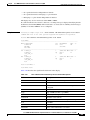
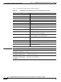
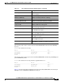
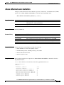
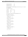
The following commands are new or have been modified with Cisco MWR 2941 Release 3.5:
•
errdisable recovery, page -98
•
ip rtp header-compression, page -192
•
platform header-compression match access-group, page -301
•
show ip rtp header-compression, page -549
•
show platform hardware, page -578
•
show storm-control, page -617
•
show storm-control history, page -619
•
storm-control, page -666
Cisco MWR 2941 Mobile Wireless Edge Router Release 3.5 Command Reference, Cisco IOS Release 15.1(3)MR
OL-26895-01
1
Chapter
Cisco MWR 2941 Router Command Reference, Release 15.1(3)MR
ais
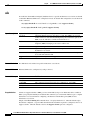
ais
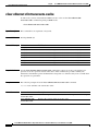
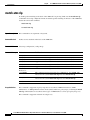
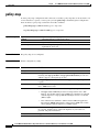
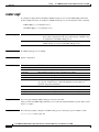
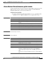
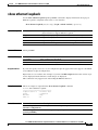
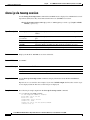
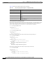
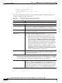
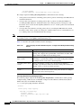
To enable the Alarm Indication Signal (AIS) function for a specific maintenance association, use the ais
command in Ethernet CFM service configuration mode. To disable AIS configuration, use the no form
of this command.
ais [expiry-threshold threshold | level level-id | period seconds | suppress-alarms]
no ais [expiry-threshold | level | period | suppress-alarms]
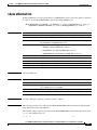
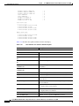
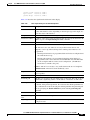
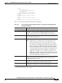
Syntax Description
expiry-threshold
(Optional) Configures the expiry threshold.
threshold
(Optional) Integer from 2 to 255 that is a count. If no MEPs are received
within an interval of the threshold multiplied by the transmission period, the
MEP clears the AIS defect condition. The default is 3.5.
level
(Optional) Indicates a maintenance level where AIS frames for maintenance
endpoints (MEPs) belonging to the service will be sent.
level-id
(Optional) Integer from 0 to 7 that identifies the maintenance level.
period
(Optional) Configures the AIS transmission period for all MEPs in the
maintenance association.
seconds
(Optional) Integer value 1 or 60 that indicates the AIS transmission period
in seconds. The default is 60.
suppress-alarms
(Optional) Configures alarm suppression.
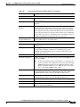
Command Default
The AIS function is enabled on specific maintenance associations.
Command Modes
Ethernet CFM service configuration (config-ecfm-srv)
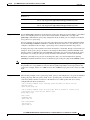
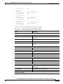
Command History
Release
Modification
15.0(1)XA
This command was introduced.
12.2(33)SRE
This command was integrated into Cisco IOS Release 12.2(33)SRE.
15.0(1)MR
This command was integrated into Cisco IOS Release 15.0(1)MR.
15.1(3)MR
This command was integrated into Cisco IOS Release 15.1(3)MR.
Usage Guidelines
Alarms are suppressed when a MEP goes into an RX AIS (receipt of an AIS frame) defect condition.
When you specify the level keyword with the ais command, you can transmit AIS messages to a higher
maintenance association without configuring a maintenance intermediate point (MIP) for that
maintenance association.
Output of the show running all command shows “ais expiry-threshold 3.5” when the default expiry
threshold is configured, “ais period 60” when the default transmission period is configured, and “no ais
suppress-alarms” when the default value for the suppress-alarms option is configured.
Cisco MWR 2941 Mobile Wireless Edge Router Release 3.5 Command Reference, Cisco IOS Release 15.1(3)MR
-2
OL-26895-01
Chapter
Cisco MWR 2941 Router Command Reference, Release 15.1(3)MR
ais
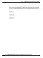
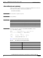
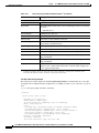
Examples
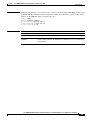
The following example shows how to enable the AIS function at level 5 with a transmission period of
one second:
Router(config)# ethernet cfm
Router(config-ecfm)# service
Router(config-ecfm-srv)# ais
Router(config-ecfm-srv)# ais
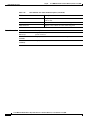
Related Commands
domain operatorA level 5
vlan-id 10 port
period 1
level 5
Command
Description
ethernet cfm global
Enables connectivity fault management (CFM) globally on a device.
Cisco MWR 2941 Mobile Wireless Edge Router Release 3.5 Command Reference, Cisco IOS Release 15.1(3)MR
OL-26895-01
-3
Chapter
Cisco MWR 2941 Router Command Reference, Release 15.1(3)MR
alarm
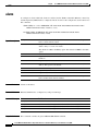
alarm
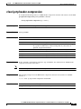
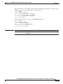
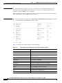
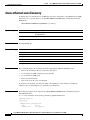
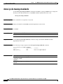
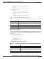
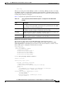
To configure an alarm when fault alarms are enabled, use the alarm command in Ethernet connectivity
fault management (CFM) interface configuration mode. To remove the configuration, use the no form of
this command.
alarm {delay mseconds | notification {all | error-xcon | mac-remote-error-xcon | none |
remote-error-xcon | xcon} | reset mseconds}
no alarm {delay | notification {all | error-xcon | mac-remote-error-xcon | none |
remote-error-xcon | xcon} | reset}
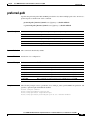
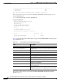
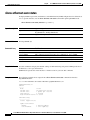
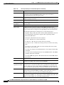
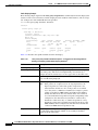
Syntax Description
delay
Sets a delay time value during which one or more defects must be present
before a fault alarm is issued.
mseconds
Integer from 2500 to 10000 that specifies the number of milliseconds for
either a delay or a reset of an alarm.
The default is 2500 for the delay option. The default is 10000 for the reset
option.
notification
Sets the defects that are to be reported if fault alarms are enabled.
all
Reports all defects: DefRDI, DefMACStatus, DefRemote, DefError, and
DefXcon.
error-xcon
Reports only DefError and DefXcon defects.
mac-remote-error-xcon Reports only DefMACStatus, DefRemote, DefError, and DefXcon (default)
defects. This option is the default.
none
No defects are reported.
remote-error-xcon
Reports only DefRemote, DefError, and DefXcon defects.
xcon
Reports only DefXcon defects.
reset
Sets a reset time value that, after a fault alarm, no defects must be present
before another fault alarm is enabled.
Command Default
Alarms are disabled.
Command Modes
Ethernet CFM interface configuration (config-if-ecfm-mep)
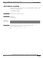
Command History
Release
Modification
12.2(33)SXI2
This command was introduced.
12.2(33)SRE
This command was integrated into Cisco IOS Release 12.2(33)SRE.
15.0(1)MR
This command was integrated into Cisco IOS Release 15.0(1)MR.
15.1(3)MR
This command was integrated into Cisco IOS Release 15.1(3)MR.
Usage Guidelines
This command overrides the global ethernet cfm alarm command.
Cisco MWR 2941 Mobile Wireless Edge Router Release 3.5 Command Reference, Cisco IOS Release 15.1(3)MR
-4
OL-26895-01
Chapter
Cisco MWR 2941 Router Command Reference, Release 15.1(3)MR
alarm
If a higher priority defect occurs after a lower priority defect has triggered an alarm but before the alarm
has reset, immediately issue another fault alarm for the higher priority defect.
Output of the show running all command displays “alarm delay 2500” when the default value for the
delay option is configured, “alarm mac-remote-error-xcon” when the default value for the notification
option is configured, and “alarm reset 10000” when the default value for the reset option is configured.
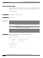
Examples
The following example shows how to set up notifications for all defects:
Router(config)# ethernet cfm domain test level 5
Router(config-ecfm)# service vlan-id 17 vlan 17
Router(config-ecfm-srv)# exit
Router(config-ecfm)# exit
Router(config)# interface gigabitethernet 0/2
Router(config-if)# ethernet cfm interface
Router(config-if)# ethernet cfm mep domain test mpid 5 vlan 17
Router(config-if-ecfm-mep)# alarm notification all
Router(config-if-ecfm-mep)#
The following example shows how to set the time during which one or more defects must be
present before a fault alarm is issued to 7000 milliseconds:
Router(config)# ethernet cfm domain test level 5
Router(config-ecfm)# service vlan-id 17 vlan 17
Router(config-ecfm-srv)# exit
Router(config-ecfm)# exit
Router(config)# interface gigabitethernet 0/2
Router(config-if)# ethernet cfm interface
Router(config-if)# ethernet cfm mep domain test mpid 5 vlan 17
Router(config-if-ecfm-mep)# alarm delay 7000
Related Commands
Command
Description
ethernet cfm alarm
Configures an alarm for Ethernet CFM.
show running all
Shows the running configuration with default values.
Cisco MWR 2941 Mobile Wireless Edge Router Release 3.5 Command Reference, Cisco IOS Release 15.1(3)MR
OL-26895-01
-5
Chapter
Cisco MWR 2941 Router Command Reference, Release 15.1(3)MR
atm ilmi-keepalive
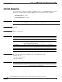
atm ilmi-keepalive
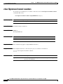
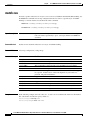
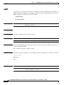
To enable Interim Local Management Interface (ILMI) keepalives, use the atm ilmi-keepalive command
in interface configuration mode. To disable ILMI keepalives, use the no form of this command.
atm ilmi-keepalive [seconds]
no atm ilmi-keepalive [seconds]
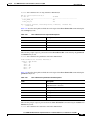
Syntax Description
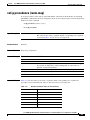
seconds
Command Default
3 seconds
Command Modes
Interface configuration
Command History
Release
Modification
11.0
This command was introduced.
12.2(33)SRA
This command was integrated into Cisco IOS Release 12.2(33)SRA.
12.2SX
This command is supported in the Cisco IOS Release 12.2SX train. Support
in a specific 12.2SX release of this train depends on your feature set,
platform, and platform hardware.
12.4(20)MR
This command was integrated into Cisco IOS Release 12.4(20)MR.
12.2(33)MRA
This command was integrated into Cisco IOS Release 12.2(33)MRA.
15.0(1)MR
This command was integrated into Cisco IOS Release 15.0(1)MR.
15.1(3)MR
This command was integrated into Cisco IOS Release 15.1(3)MR.
Examples
(Optional) Number of seconds between keepalives. Values less than 3 seconds are
rounded up to 3 seconds, and there is no upper limit.
The following example enables ILMI keepalives for the ATM interface 1/0:
interface atm 1/0
atm address-registration
atm ilmi-keepalive
Related Commands
Command
Description
atm address-registration
Enables the router to engage in address registration and
callback functions with the ILMI.
Cisco MWR 2941 Mobile Wireless Edge Router Release 3.5 Command Reference, Cisco IOS Release 15.1(3)MR
-6
OL-26895-01
Chapter
Cisco MWR 2941 Router Command Reference, Release 15.1(3)MR
atm vc-per-vp
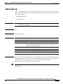
atm vc-per-vp
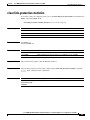
To set the maximum number of virtual channel identifier (VCIs) to support per virtual path identifier
(VPI), use the atm vc-per-vp interface configuration command. To restore the default value, use the no
form of this command.
atm vc-per-vp number
no atm vc-per-vp
Syntax Description
number Maximum number of VCIs to support per VPI. Valid values are: 16, 128, 256, 1024, 2048,
4096, 16384, and 65536.
Defaults
1024
Command Modes
Interface configuration
Command History
Release
Modification
11.0
This command was introduced.
12.2(33)SRA
This command was integrated into Cisco IOS Release 12.2(33)SRA.
12.2SX
This command is supported in the Cisco IOS Release 12.2SX train. Support
in a specific 12.2SX release of this train depends on your feature set,
platform, and platform hardware.
12.4(20)MR
This command was integrated into Cisco IOS Release 12.4(20)MR.
12.2(33)MRA
This command was integrated into Cisco IOS Release 12.2(33)MRA.
15.0(1)MR
This command was integrated into Cisco IOS Release 15.0(1)MR.
15.1(3)MR
This command was integrated into Cisco IOS Release 15.1(3)MR.
Usage Guidelines
This command controls the memory allocation in the ATM Interface Processor (AIP), ATM port adapter,
ATM network module, or network processor module (NPM) to deal with the VCI table. It defines the
maximum number of VCIs to support per VPI; it does not bound the VCI numbers.
An invalid VCI causes a warning message to be displayed.
Note
Changing the value of the atm vc-per-vp command on one interface affects all of the interfaces on that
network module.
Cisco MWR 2941 Mobile Wireless Edge Router Release 3.5 Command Reference, Cisco IOS Release 15.1(3)MR
OL-26895-01
-7
Chapter
Cisco MWR 2941 Router Command Reference, Release 15.1(3)MR
atm vc-per-vp
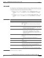
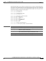
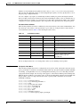
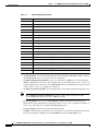
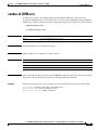
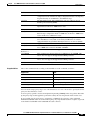
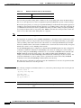
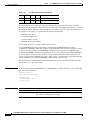
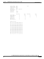
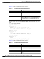
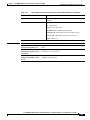
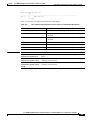
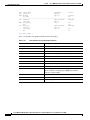
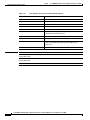
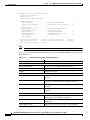
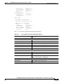
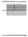
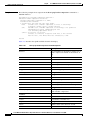
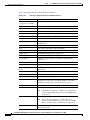
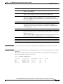
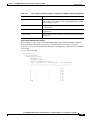
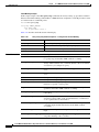
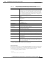
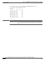
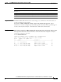
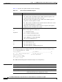
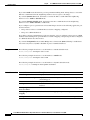
Table 1-1 lists the possible VCI ranges and corresponding VPI ranges.
Table 1-1
Examples
VCI and VPI Ranges for Cisco 2600 and 3600 Series with IMA
VCI Range
VPI Range
0–255
0–15, 64–79, 128–143, and 192–207
0–511
0–15, 64–79
0–1023
0–15
The following example sets the maximum number of VCIs per VPI to 512:
Router(config)# interface atm1/0
Router(config-if)# atm vc-per-vp 512
Related Commands
Command
Description
pvc
Configures the PVC interface.
Cisco MWR 2941 Mobile Wireless Edge Router Release 3.5 Command Reference, Cisco IOS Release 15.1(3)MR
-8
OL-26895-01
Chapter
Cisco MWR 2941 Router Command Reference, Release 15.1(3)MR
backup delay
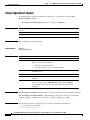
backup delay
To specify how long a backup pseudowire (PW) virtual circuit (VC) should wait before resuming
operation after the primary PW VC goes down, use the backup delay command in interface
configuration mode or xconnect configuration mode. To return to the default so that as soon as the
primary fails, the secondary is immediately brought up without delay, use the no form of this command.
backup delay enable-delay {disable-delay | never}
no backup delay enable-delay {disable-delay | never}
Syntax Description
enable-delay
Number of seconds that elapse after the primary PW VC goes down before the
Cisco IOS software activates the secondary PW VC. The range is 0 to 180.
The default is 0.
disable-delay
Number of seconds that elapse after the primary PW VC comes up before the
Cisco IOS software deactivates the secondary PW VC. The range is 0 to 180.
The default is 0.
never
The secondary PW VC does not fall back to the primary PW VC if the primary
PW VC becomes available again, unless the secondary PW VC fails.
Command Default
If a failover occurs, the xconnect redundancy algorithm immediately switches over or falls back to the
backup or primary member in the redundancy group.
Command Modes
Interface configuration
Xconnect configuration
Command History
Examples
Release
Modification
10.0
This command was introduced.
12.2(33)SRB1
This command was integrated into Cisco IOS Release 12.2(33)SRB1.
12.4(19)MR2
This command was integrated into Cisco IOS Release 12.4(19)MR2.
12.2(33)MRA
This command was integrated into Cisco IOS Release 12.2(33)MRA.
15.0(1)MR
This command was integrated into Cisco IOS Release 15.0(1)MR.
15.1(3)MR
This command was integrated into Cisco IOS Release 15.1(3)MR.
The following example shows a Multiprotocol Label Switching (MPLS) xconnect with one redundant
peer. After a switchover to the secondary VC occurs, there is no fallback to the primary VC unless the
secondary VC fails.
Router# config t
Router(config)# pseudowire-class mpls
Router(config-pw-class)# encapsulation mpls
Router(config-pw-class)# exit
Router(config)# interface atm1/0
Router(config-if)# xconnect 10.0.0.1 50 pw-class mpls
Cisco MWR 2941 Mobile Wireless Edge Router Release 3.5 Command Reference, Cisco IOS Release 15.1(3)MR
OL-26895-01
-9
Chapter
Cisco MWR 2941 Router Command Reference, Release 15.1(3)MR
backup delay
Router(config-if-xconn)# backup peer 10.0.0.2 50
Router(config-if-xconn)# backup delay 0 never
Router(config-if-xconn)# exit
Router(config-if)# exit
Router(config)# exit
The following example shows an MPLS xconnect with one redundant peer. The switchover does not
begin unless the PW has been down for 3 seconds. After a switchover to the secondary VC occurs, there
is no fallback to the primary until the primary VC has been reestablished and is up for 10 seconds.
Router# config t
Router(config)# pseudowire-class mpls
Router(config-pw-class)# encapsulation mpls
Router(config-pw-class)# exit
Router(config)# interface atm1/0
Router(config-if)# xconnect 10.0.0.1 50 pw-class mpls
Router(config-if-xconn)# backup peer 10.0.0.2 50
Router(config-if-xconn)# backup delay 3 10
Router(config-if-xconn)# exit
Router(config-if)# exit
Router(config)# exit
Related Commands
Command
Description
backup peer
Configures a redundant peer for a PW VC.
Cisco MWR 2941 Mobile Wireless Edge Router Release 3.5 Command Reference, Cisco IOS Release 15.1(3)MR
-10
OL-26895-01
Chapter
Cisco MWR 2941 Router Command Reference, Release 15.1(3)MR
backup peer
backup peer
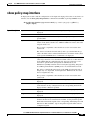
To specify a redundant peer for a pseudowire (PW) virtual circuit (VC), use the backup peer command
in interface configuration mode or xconnect configuration mode. To remove the redundant peer, use the
no form of this command.
backup peer peer-router-ip-addr vcid [pw-class pw-class-name]
no backup peer peer-router-ip-addr vcid
Syntax Description
peer-router-ipaddr
IP address of the remote peer.
vcid
The 32-bit identifier of the VC between the routers at each end of the layer control
channel.
pw-class
(Optional) PW type. If not specified, the PW type is inherited from the parent
xconnect.
pw-class-name
(Optional) Name of the PW you created when you established the PW class.
Command Default
No redundant peer is established.
Command Modes
Interface configuration
Xconnect configuration
Command History
Release
Modification
12.0(31)S
This command was introduced.
12.2(28)SB
This command was integrated into Cisco IOS Release 12.2(28)SB.
12.4(11)T
This command was integrated into Cisco IOS Release 12.4(11)T.
12.2(33)SRB
This command was integrated into Cisco IOS Release 12.2(33)SRB.
12.2(33)SXI
This command was integrated into Cisco IOS Release 12.2(33)SXI.
12.4(19)MR2
This command was integrated into Cisco IOS Release 12.4(19)MR2.
12.2(33)MRA
This command was integrated into Cisco IOS Release 12.2(33)MRA.
15.0(1)MR
This command was integrated into Cisco IOS Release 15.0(1)MR.
15.1(3)MR
This command was integrated into Cisco IOS Release 15.1(3)MR.
Usage Guidelines
The combination of the peer-router-ip-addr and vcid arguments must be unique on the router.
Examples
The following example shows an MPLS xconnect with one redundant peer:
Router# config t
Router(config)# pseudowire-class mpls
Router(config-pw-class)# encapsulation mpls
Cisco MWR 2941 Mobile Wireless Edge Router Release 3.5 Command Reference, Cisco IOS Release 15.1(3)MR
OL-26895-01
-11
Chapter
Cisco MWR 2941 Router Command Reference, Release 15.1(3)MR
backup peer
Router(config-pw-class)# exit
Router(config)# interface atm1/0
Router(config-if)# xconnect 10.0.0.1 100 pw-class mpls
Router(config-if-xconn)# backup peer 10.0.0.2 200
Router(config-if-xconn)# exit
Router(config-if)# exit
Router(config)# exit
The following example shows a backup peer configuration for an ATM interface:
Router# config t
Router(config)# pseudowire-class mpls
Router(config-pw-class)# encapsulation mpls
Router(config-pw-class)# exit
Router(config)# interface atm0/1
Router(config-if)# xconnect 10.0.0.2 1 pw-class mpls
Router(config-if-xconn)# backup peer 10.0.0.2 100 pw-class mpls
Router(config-if-xconn)# exit
Router(config-if)# exit
Router(config)# exit
Related Commands
Command
Description
backup delay
Specifies how long the backup PW VC should wait before resuming
operation after the primary PW VC goes down.
Cisco MWR 2941 Mobile Wireless Edge Router Release 3.5 Command Reference, Cisco IOS Release 15.1(3)MR
-12
OL-26895-01
Chapter
Cisco MWR 2941 Router Command Reference, Release 15.1(3)MR
bandwidth (policy-map class)
bandwidth (policy-map class)
To specify or modify the bandwidth allocated for a class belonging to a policy map, or to enable ATM
overhead accounting, use the bandwidth command in policy-map class configuration mode. To remove
the bandwidth specified for a class or disable ATM overhead accounting, use the no form of this
command.
bandwidth {bandwidth-kbps | remaining percent percentage | percent percentage}
no bandwidth
Syntax Description
Command Default
bandwidth-kbps
Amount of bandwidth, in kilobits per second (kbps), to be assigned to the
class. The amount of bandwidth varies according to the interface and platform
in use.
remaining percent
percentage
Percentage of guaranteed bandwidth based on a relative percent of available
bandwidth. The range is from 1 to 100.
percent percentage
Percentage of guaranteed bandwidth based on an absolute percent of available
bandwidth that is set aside for the priority class. The range is from 1 to 100.
No bandwidth is specified.
ATM overhead accounting is disabled.
Command Modes
Policy-map class configuration (config-pmap-c)
Command History
Release
Modification
12.0(5)T
This command was introduced.
12.0(5)XE
This command was integrated into Cisco IOS Release 12.0(5)XE and was
implemented on Versatile Interface Processor (VIP)-enabled Cisco 7500
series routers.
12.0(7)T
The percent keyword was added.
12.0(17)SL
This command was introduced on the Cisco 10000 series router.
12.0(22)S
Support for the percent keyword was added on the Cisco 10000 series router.
12.0(23)SX
Support for the remaining percent keyword was added on the Cisco 10000
series router.
12.1(5)T
This command was implemented on VIP-enabled Cisco 7500 series routers.
12.2(2)T
The remaining percent keyword was added.
12.2(28)SB
This command was integrated into Cisco IOS Release 12.2(28)SB.
12.2(31)SB
This command was implemented on the Cisco 10000 series routers.
12.2(31)SB2
This command was introduced on the PRE3 for the Cisco 10000 series router,
and was enhanced for ATM overhead accounting on the Cisco 10000 series
router for the PRE3.
12.2(33)SRA
This command was integrated into Cisco IOS Release 12.2(33)SRA.
Cisco MWR 2941 Mobile Wireless Edge Router Release 3.5 Command Reference, Cisco IOS Release 15.1(3)MR
OL-26895-01
-13
Chapter
Cisco MWR 2941 Router Command Reference, Release 15.1(3)MR
bandwidth (policy-map class)
Usage Guidelines
Release
Modification
12.2SX
This command is supported in the Cisco IOS Release 12.2SX train. Support
in a specific 12.2SX release of this train depends on your feature set,
platform, and platform hardware.
12.2(31)SB6
This command was enhanced to specify an offset size when calculating ATM
overhead and was implemented on the Cisco 10000 series router for the
PRE3.
12.2(33)SRC
Support for the Cisco 7600 series router was added.
12.2(33)SB
Support for the Cisco 7300 series router was added.
12.4(20)T
Support was added for hierarchical queueing framework (HQF) using the
Modular Quality of Service (QoS) Command-Line Interface (CLI) (MQC).
Cisco IOS XE
Release 2.1
This command was implemented on Cisco ASR 1000 series routers.
12.4(20)MR
This command was integrated into Cisco IOS Release 12.4(20)MR.
12.2(33)MRA
This command was integrated into Cisco IOS Release 12.2(33)MRA.
15.0(1)MR
This command was integrated into Cisco IOS Release 15.0(1)MR.
15.1(3)MR
This command was integrated into Cisco IOS Release 15.1(3)MR.
Configuring a Policy Map
Use the bandwidth command when you configure a policy map for a class defined by the class-map
command. The bandwidth command specifies the bandwidth for traffic in that class. Class-based
weighted fair queueing (CBWFQ) derives the weight for packets belonging to the class from the
bandwidth allocated to the class. CBWFQ then uses the weight to ensure that the queue for the class is
serviced fairly.
Configuring Strict Priority with Bandwidth
You can configure only one class with strict priority. Other classes cannot have priority or bandwidth
configuration. To configure minimum bandwidth for another class, use the bandwidth remaining
percent command.
Specifying Bandwidth as a Percentage
Besides specifying the amount of bandwidth in kilobits per second (kbps), you can specify bandwidth
as a percentage of either the available bandwidth or the total bandwidth. During periods of congestion,
the classes are serviced in proportion to their configured bandwidth percentages. The bandwidth
percentage is based on the interface bandwidth or when used in a hierarchical policy. Available
bandwidth is equal to the interface bandwidth minus the sum of all bandwidths reserved by the Resource
Reservation Protocol (RSVP) feature, the IP RTP Priority feature, and the low latency queueing (LLQ)
feature.
Note
It is important to remember that when the bandwidth remaining percent command is configured, hard
bandwidth guarantees may not be provided and only relative bandwidths are assured. That is, class
bandwidths are always proportional to the specified percentages of the interface bandwidth. When the
link bandwidth is fixed, class bandwidth guarantees are in proportion to the configured percentages. If
the link bandwidth is unknown or variable, the router cannot compute class bandwidth guarantees in
kbps.
Cisco MWR 2941 Mobile Wireless Edge Router Release 3.5 Command Reference, Cisco IOS Release 15.1(3)MR
-14
OL-26895-01
Chapter
Cisco MWR 2941 Router Command Reference, Release 15.1(3)MR
bandwidth (policy-map class)
The router converts the specified bandwidth to the nearest multiple of 1/255 (ESR–PRE1) or 1/65,535
(ESR–PRE2) of the interface speed. Use the show policy-map interface command to display the actual
bandwidth.
Restrictions
The following restrictions apply to the bandwidth command:
Related Commands
•
The amount of bandwidth configured should be large enough to also accommodate Layer 2
overhead.
•
A policy map can have all the class bandwidths specified in kbps or all the class bandwidths
specified in percentages, but not a mix of both in the same class. However, the unit for the priority
command in the priority class can be different from the bandwidth unit of the nonpriority class.
•
When the bandwidth percent command is configured, and a policy map containing class policy
configurations is attached to the interface to stipulate the service policy for that interface, available
bandwidth is assessed. If a policy map cannot be attached to a particular interface because of
insufficient interface bandwidth, the policy is removed from all interfaces to which it was
successfully attached. This restriction does not apply to the bandwidth remaining percent
command.
Command
Description
class (policy-map)
Specifies the name of the class whose policy you want to create or
change, and the default class (commonly known as the
class-default class) before you configure its policy.
class-map
Creates a class map to be used for matching packets to a specified
class.
max-reserved-bandwidth
Changes the percent of interface bandwidth allocated for
CBWFQ, LLQ, and IP RTP Priority.
policy-map
Creates or modifies a policy map that can be attached to one or
more interfaces to specify a service policy.
priority
Specifies the priority of a class of traffic belonging to a policy
map.
queue-limit
Specifies or modifies the maximum number of packets the queue
can hold for a class policy configured in a policy map.
show policy-map
Displays the configuration of all classes for a specified service
policy map or all classes for all existing policy maps.
show policy-map interface
Displays the packet statistics of all classes that are configured for
all service policies either on the specified interface or subinterface
or on a specific PVC on the interface.
Cisco MWR 2941 Mobile Wireless Edge Router Release 3.5 Command Reference, Cisco IOS Release 15.1(3)MR
OL-26895-01
-15
Chapter
Cisco MWR 2941 Router Command Reference, Release 15.1(3)MR
bfd all-interfaces
bfd all-interfaces
To enable Bidirectional Forwarding Detection (BFD) for all interfaces participating in the routing
process, use the bfd all-interfaces command in router configuration mode. To disable BFD for all
interfaces, use the no form of this command.
bfd all-interfaces
no bfd all-interfaces
Syntax Description
This command has no arguments or keywords.
Command Default
BFD is not enabled on the interfaces participating in the routing process.
Command Modes
Router configuration
Command History
Release
Modification
12.2(18)SXE
This command was introduced.
12.0(31)S
This command was integrated into Cisco IOS Release 12.0(31)S.
12.4(4)T
This command was integrated into Cisco IOS Release 12.4(4)T.
12.2(33)SRA
This command was integrated into Cisco IOS Release 12.2(33)SRA.
12.4(20)MR
This command was integrated into Cisco IOS Release 12.4(20)MR.
12.2(33)MRA
This command was integrated into Cisco IOS Release 12.2(33)MRA.
15.0(1)MR
This command was integrated into Cisco IOS Release 15.0(1)MR.
15.1(3)MR
This command was integrated into Cisco IOS Release 15.1(3)MR.
Usage Guidelines
There are two methods to configure routing protocols to use BFD for failure detection. To enable BFD
for all neighbors of a routing protocol, enter the bfd all-interfaces command in router configuration
mode. If you do not want to enable BFD on all interfaces, enter the bfd interface command in router
configuration mode.
Examples
The following example shows BFD enabled for all Intermediate System-to-Intermediate System (IS-IS)
neighbors:
Router> enable
Router# configure terminal
Router(config)# router isis tag1
Router(config-router)# bfd all-interfaces
Router(config-router)# end
The following example shows BFD enabled for all Open Shortest Path First (OSPF) neighbors:
Router> enable
Router# configure terminal
Cisco MWR 2941 Mobile Wireless Edge Router Release 3.5 Command Reference, Cisco IOS Release 15.1(3)MR
-16
OL-26895-01
Chapter
Cisco MWR 2941 Router Command Reference, Release 15.1(3)MR
bfd all-interfaces
Router(config)# router ospf 123
Router(config-router)# bfd all-interfaces
Router(config-router)# end
Related Commands
Command
Description
bfd
Sets the baseline BFD session parameters on an interface.
bfd interface
Enables BFD on a per-interface basis for a BFD peer.
Cisco MWR 2941 Mobile Wireless Edge Router Release 3.5 Command Reference, Cisco IOS Release 15.1(3)MR
OL-26895-01
-17
Chapter
Cisco MWR 2941 Router Command Reference, Release 15.1(3)MR
bfd interval
bfd interval
To set the baseline Bidirectional Forwarding Detection (BFD) session parameters on an interface, use
the bfd command in interface configuration mode. To remove the baseline BFD session parameters, use
the no form of this command.
bfd interval milliseconds min_rx milliseconds multiplier multiplier-value
no bfd interval milliseconds min_rx milliseconds multiplier multiplier-value
Syntax Description
interval milliseconds
Specifies the rate at which BFD control packets will be sent to BFD peers.
The configurable time period for the milliseconds argument is from 50 to 999
milliseconds (ms).
min_rx milliseconds
Specifies the rate at which BFD control packets will be expected to be
received from BFD peers. The configurable time period for the milliseconds
argument is from 1 to 999 milliseconds (ms).
multiplier
multiplier-value
Specifies the number of consecutive BFD control packets that must be
missed from a BFD peer before BFD declares that the peer is unavailable and
the Layer 3 BFD peer is informed of the failure. The configurable value
range for the multiplier-value argument is from 3 to 50.
Command Default
No baseline BFD session parameters are set.
Command Modes
Interface configuration (config-if)
Command History
Release
Modification
12.2(18)SXE
This command was introduced.
12.0(31)S
This command was integrated into Cisco IOS Release 12.0(31)S.
12.4(4)T
This command was integrated into Cisco IOS Release 12.4(4)T.
Examples
12.2(33)SRA
This command was integrated into Cisco IOS Release 12.2(33)SRA.
12.2(33)SB
This command was integrated into Cisco IOS Release 12.2(33)SB.
12.4(20)MR
This command was integrated into Cisco IOS Release 12.4(20)MR.
12.2(33)MRA
This command was integrated into Cisco IOS Release 12.2(33)MRA.
15.0(1)MR
This command was integrated into Cisco IOS Release 15.0(1)MR.
15.1(3)MR
This command was integrated into Cisco IOS Release 15.1(3)MR.
The following example shows the BFD session parameters set for Fast Ethernet interface 3/0:
Router> enable
Router# configure terminal
Router(config)# interface vlan1
Router(config-if)# bfd interval 50 min_rx 3 multiplier 3
Router(config-if)# end
Cisco MWR 2941 Mobile Wireless Edge Router Release 3.5 Command Reference, Cisco IOS Release 15.1(3)MR
-18
OL-26895-01
Chapter
Cisco MWR 2941 Router Command Reference, Release 15.1(3)MR
bfd interval
Related Commands
Command
Description
bfd all-interfaces
Enables BFD for all interfaces for a BFD peer.
bfd interface
Enables BFD on a per-interface basis for a BFD peer.
ip ospf bfd
Enables BFD on a specific interface configured for OSPF.
Cisco MWR 2941 Mobile Wireless Edge Router Release 3.5 Command Reference, Cisco IOS Release 15.1(3)MR
OL-26895-01
-19
Chapter
Cisco MWR 2941 Router Command Reference, Release 15.1(3)MR
cbr
cbr
To configure the constant bit rate (CBR) for the ATM circuit emulation service (CES) for an ATM
permanent virtual circuit (PVC), use the cbr command in the appropriate configuration mode. To restore
the default, use the no form of this command.
cbr rate
no cbr rate
Syntax Description
rate
Command Default
The CBR is not configured.
Command Modes
Interface-ATM-VC configuration (for ATM PVCs and SVCs)
PVC range configuration (for an ATM PVC range)
PVC-in-range configuration (for an individual PVC within a PVC range)
ATM PVP configuration
Command History
Release
Examples
Constant bit rate (also known as the average cell rate) for ATM CES. Valid
values are 32–1920 kbps.
Modification
12.0
This command was introduced for the ATM CES on the Cisco MC3810.
12.1(5)T
This command was made available in PVC range and PVC-in-range
configuration modes.
12.2(5)
Support was added for the PA-A3 port adapter on the Cisco 7200 series
routers.
12.2(7)
Support was added for the PA-A3 port adapter on the Cisco 7500 series
routers.
12.2(33)SRA
This command was integrated into Cisco IOS Release 12.2(33)SRA.
12.2SX
This command is supported in the Cisco IOS Release 12.2SX train. Support
in a specific 12.2SX release of this train depends on your feature set,
platform, and platform hardware.
Cisco IOS XE Release
2.3
This command was made available in ATM PVP configuration mode.
12.4(20)MR
This command was integrated into Cisco IOS Release 12.4(20)MR.
12.2(33)MRA
This command was integrated into Cisco IOS Release 12.2(33)MRA.
15.0(1)MR
This command was integrated into Cisco IOS Release 15.0(1)MR.
15.1(3)MR
This command was integrated into Cisco IOS Release 15.1(3)MR.
The following example configures the constant bit rate on ATM PVC 20:
pvc 20
cbr 56
Cisco MWR 2941 Mobile Wireless Edge Router Release 3.5 Command Reference, Cisco IOS Release 15.1(3)MR
-20
OL-26895-01
Chapter
Cisco MWR 2941 Router Command Reference, Release 15.1(3)MR
cbr
Related Commands
Command
Description
pvc
Creates or assigns a name to an ATM PVC, specifies the encapsulation type
on an ATM PVC, and enters interface-ATM-VC configuration mode.
Cisco MWR 2941 Mobile Wireless Edge Router Release 3.5 Command Reference, Cisco IOS Release 15.1(3)MR
OL-26895-01
-21
Chapter
Cisco MWR 2941 Router Command Reference, Release 15.1(3)MR
cdp enable
cdp enable
To enable Cisco Discovery Protocol (CDP) on an interface, use the cdp enable command in interface
configuration mode. To disable CDP on an interface, use the no form of this command.
cdp enable
no cdp enable
Syntax Description
This command has no arguments or keywords.
Defaults
Enabled at the global level and on all supported interfaces.
Command Modes
Interface configuration
Command History
Release
Modification
10.3
This command was introduced.
12.2(33)SRA
This command was integrated into Cisco IOS Release 12.2(33)SRA.
12.2SX
This command is supported in the Cisco IOS Release 12.2SX train. Support
in a specific 12.2SX release of this train depends on your feature set,
platform, and platform hardware.
12.4(19)MR2
This command was integrated into Cisco IOS Release 12.4(19)MR2.
12.2(33)MRA
This command was integrated into Cisco IOS Release 12.2(33)MRA.
15.0(1)MR
This command was integrated into Cisco IOS Release 15.0(1)MR.
15.1(3)MR
This command was integrated into Cisco IOS Release 15.1(3)MR.
Usage Guidelines
Note
Examples
CDP is enabled by default at the global level and on each supported interface in order to send or receive
CDP information. However, some interfaces, such as ATM interfaces, do not support CDP.
The cdp enable, cdp timer, and cdp run commands affect the operation of the IP on demand routing
feature (that is, the router odr global configuration command). For more information on the router odr
command, see the “On-Demand Routing Commands” chapter in the Cisco IOS Command Reference,
Volume 2 of 3: Routing Protocols document.
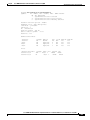
In the following example, CDP is disabled on the Ethernet 0 interface only:
Router# show cdp
Global CDP information
Sending CDP packets every 60 seconds
Sending a holdtime value of 180 seconds
Sending CDPv2 advertisements is enabled
Router# config terminal
Cisco MWR 2941 Mobile Wireless Edge Router Release 3.5 Command Reference, Cisco IOS Release 15.1(3)MR
-22
OL-26895-01
Chapter
Cisco MWR 2941 Router Command Reference, Release 15.1(3)MR
cdp enable
Router(config)# interface ethernet 0
Router(config-if)# no cdp enable
Related Commands
Command
Description
cdp run
Reenables CDP on a Cisco device.
cdp timer
Specifies how often the Cisco IOS software sends CDP updates.
router odr
Enables on-demand routing on a hub router.
Cisco MWR 2941 Mobile Wireless Edge Router Release 3.5 Command Reference, Cisco IOS Release 15.1(3)MR
OL-26895-01
-23
Chapter
Cisco MWR 2941 Router Command Reference, Release 15.1(3)MR
cem-group
cem-group
To create a circuit emulation (CEM) channel from one or more time slots of a T1 or E1 line, use the
cem-group command in controller configuration mode. To remove a CEM group and release the
associated time slots, use the no form of this command.
cem-group group-number {unframed | timeslots time-slot-range}
no cem-group group-number
Syntax Description
group-number
CEM identifier to be used for this group of time slots:
•
For T1 ports, the range is from 0 to 23.
•
For E1 ports, the range is from 0 to 30.
unframed
Specifies that a single CEM channel is being created, including all time
slots, without specifying the framing structure of the line.
timeslots
Specifies that a list of time slots is to be used as specified by the
time-slot-range argument.
time-slot-range—Specifies the time slots to be included in the CEM
channel. The list of time slots may include commas and hyphens with no
spaces between the numbers.
Defaults
No CEM groups are defined.
Command Modes
Controller configuration
Command History
Release
Modification
12.3(7)T
This command was introduced.
12.4(12)MR2
This command was integrated into Cisco IOS Release 12.4(12)MR2.
12.2(33)MRA
This command was integrated into Cisco IOS Release 12.2(33)MRA.
15.0(1)MR
This command was integrated into Cisco IOS Release 15.0(1)MR.
15.1(3)MR
This command was integrated into Cisco IOS Release 15.1(3)MR.
Usage Guidelines
Use this command to create CEM channels on the T1 or E1 port.
Examples
The following example shows how to create a CEM channel:
SATOP
Router# config t
Router(config)# controller el 0/0
Router(config-controller)# cem-group 0 unframed
Router(config-controller)# exit
Cisco MWR 2941 Mobile Wireless Edge Router Release 3.5 Command Reference, Cisco IOS Release 15.1(3)MR
-24
OL-26895-01
Chapter
Cisco MWR 2941 Router Command Reference, Release 15.1(3)MR
cem-group
Router(config)# interface cem 0/0
Router(config-if)# cem 0
Router(config-if-cem)# xconnect 10.10.10.10 200 encapsulation mpls
Router(config-if-cem-xconn)# exit
Router(config-if-cem)# exit
Router(config-if)# exit
Router(config)# exit
CESoPSN
Router# config t
Router(config)# controller el 0/1
Router(config-controller)# cem-group 0 timeslots 1-31
Router(config-controller)# exit
Router(config)# interface cem 0/1
Router(config-if)# cem 0
Router(config-if-cem)# xconnect 10.10.10.10 200 encapsulation mpls
Router(config-if-cem-xconn)# exit
Router(config-if-cem)# exit
Router(config-if)# exit
Router(config)# exit
Related Commands
Command
Description
cem
Enters circuit emulation configuration mode.
Cisco MWR 2941 Mobile Wireless Edge Router Release 3.5 Command Reference, Cisco IOS Release 15.1(3)MR
OL-26895-01
-25
Chapter
Cisco MWR 2941 Router Command Reference, Release 15.1(3)MR
class (policy-map)
class (policy-map)
To specify the name of the class whose policy you want to create or change or to specify the default class
(commonly known as the class-default class) before you configure its policy, use the class command in
policy-map configuration mode. To remove a class from the policy map, use the no form of this
command.
class {class-name | class-default}
no class {class-name | class-default}
Syntax Description
class-name
Name of the class to be configured or whose policy is to be modified. The
class name is used for both the class map and to configure a policy for the
class in the policy map.
class-default
Specifies the default class so that you can configure or modify its policy.
Command Default
No class is specified.
Command Modes
Policy-map configuration (config-pmap)
Command History
Release
Modification
12.0(5)T
This command was introduced.
12.0(5)XE
This command was integrated into Cisco IOS Release 12.0(5)XE.
12.0(7)S
This command was integrated into Cisco IOS Release 12.0(7)S.
12.1(1)E
This command was integrated into Cisco IOS Release 12.1(1)E.
12.2(14)SX
Support for this command was introduced on Cisco 7600 routers.
12.2(17d)SXB
This command was implemented on the Cisco 7600 router and integrated
into Cisco IOS Release 12.2(17d)SXB.
12.2(18)SXE
The class-default keyword was added to the Cisco 7600 router.
12.4(4)T
The insert-before class-name option was added.
12.2(28)SB
This command was integrated into Cisco IOS Release 12.2(28)SB.
12.2(31)SB2
This command was introduced on the PRE3 for the Cisco 10000 series
router.
12.2(18)ZY
The insert-before class-name option was integrated into Cisco IOS
Release 12.2(18)ZY on the Catalyst 6500 series of switches equipped with
the Programmable Intelligent Services Accelerator (PISA).
Cisco IOS XE
Release 2.1
This command was implemented on Cisco ASR 1000 series routers. The
fragment fragment-class-name and service-fragment fragment-class-name
options were introduced.
12.4(20)MR
This command was integrated into Cisco IOS Release 12.4(20)MR. This
release does not support the fragment, insert-before, or service-fragment
parameters.
Cisco MWR 2941 Mobile Wireless Edge Router Release 3.5 Command Reference, Cisco IOS Release 15.1(3)MR
-26
OL-26895-01
Chapter
Cisco MWR 2941 Router Command Reference, Release 15.1(3)MR
class (policy-map)
Usage Guidelines
Release
Modification
12.2(33)MRA
This command was integrated into Cisco IOS Release 12.2(33)MRA. This
release does not support the fragment, insert-before, or service-fragment
parameters.
15.0(1)MR
This command was integrated into Cisco IOS Release 15.0(1)MR. This
release does not support the fragment, insert-before, or service-fragment
parameters. The release also does not support Weighted Random Early
Detection (WRED).
15.1(3)MR
This command was integrated into Cisco IOS Release 15.1(3)MR.
Policy Map Configuration Mode
Within a policy map, the class (policy-map) command can be used to specify the name of the class whose
policy you want to create or change. First, the policy map must be identified.
To identify the policy map (and enter the required policy-map configuration mode), use the policy-map
command before you use the class (policy-map) command. After you specify a policy map, you can
configure policy for new classes or modify the policy for any existing classes in that policy map.
Class Characteristics
The class name that you specify in the policy map ties the characteristics for that class—that is, its
policy—to the class map and its match criteria, as configured using the class-map command.
When you configure policy for a class and specify its bandwidth and attach the policy map to an
interface, class-based weighted fair queueing (CBWFQ) determines if the bandwidth requirement of the
class can be satisfied. If so, CBWFQ allocates a queue for the bandwidth requirement.
When a class is removed, available bandwidth for the interface is incremented by the amount previously
allocated to the class.
The maximum number of classes that you can configure for a router—and, therefore, within a policy
map—is 64.
Predefined Default Class
The class-default keyword is used to specify the predefined default class called class-default. The
class-default class is the class to which traffic is directed if that traffic does not match any of the match
criteria in the configured class maps.
Tail Drop or WRED
You can define a class policy to use either tail drop by using the queue-limit command. When using tail
drop, note the following points:
•
The queue-limit command cannot be used in the same class policy, but can be used in two class
policies in the same policy map.
•
You can configure the bandwidth command when the queue-limit command is configured in a class
policy. The bandwidth command specifies the amount of bandwidth allocated for the class.
•
For the predefined default class, you can configure the fair-queue (class-default) command. The
fair-queue command specifies the number of dynamic queues for the default class. The fair-queue
command can be used in the same class policy as the queue-limit command. It cannot be used with
the bandwidth command.
Cisco MWR 2941 Mobile Wireless Edge Router Release 3.5 Command Reference, Cisco IOS Release 15.1(3)MR
OL-26895-01
-27
Chapter
Cisco MWR 2941 Router Command Reference, Release 15.1(3)MR
class (policy-map)
Fragments
A default traffic class is marked as a fragment within a policy map class statement using the fragment
keyword. Multiple fragments can then be classified collectively in a separate policy map that is created
using the service-fragment keyword. When fragments are used, default traffic classes marked as
fragments have QoS applied separately from the non-default traffic classes.
When using fragments, note the following guidelines:
Examples
•
Only default traffic classes can be marked as fragments.
•
The fragment fragment-class-name option within a default class statement marks that default class
as a fragment.
•
The service-fragment fragment-class-name option when defining a class in a policy map is used to
specify a class of traffic within the Modular QoS CLI that contains all fragments sharing the same
fragment-class-name.
•
Fragments can only be used within the same physical interface. Policy maps with fragments sharing
the same fragment-class-name on different interfaces cannot be classified collectively using a class
with the service-fragment fragment-class-name option.
The following example configures three class policies included in the policy map called policy1. Class1
specifies policy for traffic that matches access control list 136. Class2 specifies policy for traffic with a
CoS value of 2. The third class is the default class to which packets that do not satisfy configured match
criteria are directed.
! The following commands create class-maps class1 and class2
! and define their match criteria:
class-map class1
match access-group 136
class-map class2
match cos 2
! The following commands create the policy map, which is defined to contain policy
! specification for class1 and the default class:
policy-map policy1
Router(config)# policy-map policy1
Router(config-pmap)# class class1
Router(config-pmap-c)# bandwidth 2000
Router(config-pmap-c)# queue-limit 40
Router(config-pmap)# class class-default
Router(config-pmap-c)# fair-queue 16
Router(config-pmap-c)# queue-limit 20
Related Commands
Command
Description
bandwidth (policy-map class)
Specifies or modifies the bandwidth allocated for a class
belonging to a policy map.
class-map
Creates a class map to be used for matching packets to a specified
class.
fair-queue (class-default)
Specifies the number of dynamic queues to be reserved for use by
the class-default class as part of the default class policy.
Cisco MWR 2941 Mobile Wireless Edge Router Release 3.5 Command Reference, Cisco IOS Release 15.1(3)MR
-28
OL-26895-01
Chapter
Cisco MWR 2941 Router Command Reference, Release 15.1(3)MR
class (policy-map)
Command
Description
policy-map
Creates or modifies a policy map that can be attached to one or
more interfaces to specify a service policy.
queue-limit
Specifies or modifies the maximum number of packets the queue
can hold for a class policy configured in a policy map.
Cisco MWR 2941 Mobile Wireless Edge Router Release 3.5 Command Reference, Cisco IOS Release 15.1(3)MR
OL-26895-01
-29
Chapter
Cisco MWR 2941 Router Command Reference, Release 15.1(3)MR
class cem
class cem
To configure CEM interface parameters in a class that is applied to CEM interfaces together, use the
class cem command in global configuration mode. This command works in the same manner for CEM
interfaces as the pseudowire-class command does for xconnect.
class cem class-name
Syntax Description
class-name
Command Modes
Global configuration
Command History
Release
Usage Guidelines
Note
Examples
The name of a CEM interface parameters class.
Modification
12.4(12)MR2
This command was incorporated.
12.2(33)MRA
This command was integrated into Cisco IOS Release 12.2(33)MRA.
15.0(1)MR
This command was integrated into Cisco IOS Release 15.0(1)MR.
15.1(3)MR
This command was integrated into Cisco IOS Release 15.1(3)MR.
The class cem command allows you to configure CEM interface parameters in a class that is applied to
CEM interfaces together. A class cem command includes the following configuration settings:
•
dejitter-buffer dejitter-in-ms
•
idle-pattern 8-bit-idle-pattern
•
payload-size payload-size-in-byte
You can improve the performance of packet reordering on TDM/PWE connections by using the
increasing the size of the dejitter buffer using the dejitter-buffer parameter.
The following example shows how to configure CEM interface parameters:
Router# config t
Router(config)# class cem mycemclass
Router(config-cem-class)# dejitter-buffer 10
Router(config-cem-class)# exit
Router(config)# interface cem 0/0
Router(config-if)# no ip address
Router(config-if)# cem 0
Router(config-if-cem)# xconnect 10.10.10.10 200 encapsulation mpls
Router(config-if-cem-xconn)# cem class mycemclass
Router(config-if-cem)# exit
Router(config-if)# exit
Router(config)# exit
Cisco MWR 2941 Mobile Wireless Edge Router Release 3.5 Command Reference, Cisco IOS Release 15.1(3)MR
-30
OL-26895-01
Chapter
Cisco MWR 2941 Router Command Reference, Release 15.1(3)MR
class cem
Related Commands
Command
Description
dejitter-buffer
Specifies the size of the dejitter buffer used for network jitter in CEM
configuration mode.
idle-pattern
Specifies the data pattern to transmit on the T1/E1 line when missing
packets are detected on the PWE3 circuit in CEM configuration mode.
cem
Enters circuit emulation configuration mode.
Cisco MWR 2941 Mobile Wireless Edge Router Release 3.5 Command Reference, Cisco IOS Release 15.1(3)MR
OL-26895-01
-31
Chapter
Cisco MWR 2941 Router Command Reference, Release 15.1(3)MR
class-map
class-map
To create a class map to be used for matching packets to a specified class, use the class-map command
in global configuration mode. To remove an existing class map from the router, use the no form of this
command. The class-map command enters class-map configuration mode in which you can enter one of
the match commands to configure the match criteria for this class.
class map [match-all | match-any] class-map-name
no class map [match-all | match-any] class-map-name
Syntax Description
match-all
(Optional) Determines how packets are evaluated when multiple match
criteria exist. Matches statements under this class map based on the logical
AND function. One statement and another are accepted. If you do not
specify the match-all or match-any keyword, the default keyword is
match-all.
match-any
(Optional) Determines how packets are evaluated when multiple match
criteria exist. Matches statements under this class map based on the logical
OR function. One statement or another is accepted. If you do not specify the
match-any or match-all keyword, the default keyword is match-all.
class-map-name
Name of the class for the class map. The name can be a maximum of
40 alphanumeric characters. The class name is used for both the class map
and to configure a policy for the class in the policy map.
Command Default
No class map is configured by default.
Command Modes
Global configuration (config)
Command History
Release
Modification
12.0(5)T
This command was introduced.
12.0(5)XE
This command was integrated into Cisco IOS Release 12.0(5)XE.
12.0(7)S
This command was integrated into Cisco IOS Release 12.0(7)S.
12.1(1)E
This command was integrated into Cisco IOS Release 12.1(1)E.
12.2(14)SX
Support for this command was introduced on Cisco 7600 series routers.
12.2(17d)SXB
This command was implemented on the Cisco 7600 series routers and
integrated into Cisco IOS Release 12.2(17d)SXB.
12.2(33)SRA
This command was integrated into Cisco IOS Release 12.2(33)SRA.
12.4(4)T
The type stack and type access-control keywords were added to support
FPM. The type port-filter and type queue-threshold keywords were added
to support Control Plane Protection.
12.4(6)T
The type logging keyword was added to support control plane packet
logging.
Cisco MWR 2941 Mobile Wireless Edge Router Release 3.5 Command Reference, Cisco IOS Release 15.1(3)MR
-32
OL-26895-01
Chapter
Cisco MWR 2941 Router Command Reference, Release 15.1(3)MR
class-map
Usage Guidelines
Release
Modification
12.2(18)ZY
The type stack and type access-control keywords were integrated into
Cisco IOS Release 12.2(18)ZY on the Catalyst 6500 series of switches
equipped with the Programmable Intelligent Services Accelerator (PISA)
Cisco IOS XE
Release 2.1
This command was implemented on Cisco ASR 1000 series routers.
12.4(20)MR
This command was integrated into Cisco IOS Release 12.4(20)MR. This
release does not support the stack, access-control, logging, port-filter, and
queue-threshold parameters.
12.2(33)MRA
This command was integrated into Cisco IOS Release 12.2(33)MRA. This
release does not support the stack, access-control, logging, port-filter, and
queue-threshold parameters.
15.0(1)MR
This command was integrated into Cisco IOS Release 15.0(1)MR.
15.1(3)MR
This command was integrated into Cisco IOS Release 15.1(3)MR.
Use the class-map command to specify the class that you will create or modify to meet the class-map
match criteria. This command enters class-map configuration mode in which you can enter one of the
match commands to configure the match criteria for this class. Packets that arrive at either the input
interface or the output interface (determined by how the service-policy command is configured) are
checked against the match criteria configured for a class map to determine if the packets belong to that
class.
When configuring a class map, you can use one or more match commands to specify match criteria. For
example, you can use the match access-group command, the match protocol command, or the match
input-interface command. The match commands vary according to the Cisco IOS release. For more
information about match criteria and match commands, see the “Modular Quality of Service
Command-Line Interface (CLI) (MQC)” chapter of the Cisco IOS Quality of Service Solutions
Configuration Guide.
Examples
The following example specifies class101 as the name of a class, and it defines a class map for this class.
The class called class101 specifies policy for traffic that matches access control list 101.
Router(config)# class-map class101
Router(config-cmap)# match access-group 101
The following example shows how to access the class-map commands and subcommands, configure a
class map named ipp5, and enter a match statement for IP precedence 5:
Router(config)# class-map ipp5
Router(config-cmap)# match ip precedence 5
Related Commands
Command
Description
class (policy-map)
Specifies the name of the class whose policy you want to create or change,
and the default class (commonly known as the class-default class) before you
configure its policy.
class class-default
Specifies the default class for a service policy map.
Cisco MWR 2941 Mobile Wireless Edge Router Release 3.5 Command Reference, Cisco IOS Release 15.1(3)MR
OL-26895-01
-33
Chapter
Cisco MWR 2941 Router Command Reference, Release 15.1(3)MR
class-map
Command
Description
match (class-map)
Configures the match criteria for a class map on the basis of port filter and/or
protocol queue policies.
match access-group
Configures the match criteria for a class map on the basis of the specified
ACL.
match input-interface Configures a class map to use the specified input interface as a match
criterion.
match ip dscp
Identifies one or more DSCP, AF, and CS values as a match criterion
match mpls
experimental
Configures a class map to use the specified EXP field value as a match
criterion.
match protocol
Configures the match criteria for a class map on the basis of the specified
protocol.
policy-map
Creates or modifies a policy map that can be attached to one or more
interfaces to specify a service policy.
service-policy
Attaches a policy map to an input interface or virtual circuit (VC) or to an
output interface or VC to be used as the service policy for that interface or
VC.
show class-map
Displays class-map information.
show policy-map
interface
Displays the statistics and the configurations of the input and output policies
that are attached to an interface.
Cisco MWR 2941 Mobile Wireless Edge Router Release 3.5 Command Reference, Cisco IOS Release 15.1(3)MR
-34
OL-26895-01
Chapter
Cisco MWR 2941 Router Command Reference, Release 15.1(3)MR
class-map type control
class-map type control
To create an Intelligent Services Gateway (ISG) control class map, which defines the conditions under
which the actions of a control policy map will be executed, use the class-map type control command in
global configuration mode. To remove a control class map, use the no form of this command.
class-map type control [match-all | match-any | match-none] class-map-name
no class-map type control [match-all | match-any | match-none] class-map-name
Syntax Description
match-all
(Optional) The class map evaluates true if all of the conditions in the class
map evaluates true.
match-any
(Optional) The class map evaluates true if any of the conditions in the class
map evaluates true.
match-none
(Optional) The class map evaluates true if none of the conditions in the class
map evaluates true.
class-map-name
Name of the class map.
Command Default
A control class map is not created.
Command Modes
Global configuration
Command History
Release
Modification
12.2(28)SB
This command was introduced.
12.4(20)MR
This command was integrated into Cisco IOS Release 12.4(20)MR.
Usage Guidelines
12.2(33)MRA
This command was integrated into Cisco IOS Release 12.2(33)MRA.
15.0(1)MR
This command was integrated into Cisco IOS Release 15.0(1)MR.
15.1(3)MR
This command was integrated into Cisco IOS Release 15.1(3)MR.
A control class map specifies conditions that must be met for a control policy to be activated, and,
optionally, the event that causes the class to be evaluated. A control class map can contain multiple
conditions, each of which will evaluate to either true or false. Use the match-any, match-all, and
match-none keywords to specify which, if any, conditions must evaluate true before the control policy
will be executed.
A control policy map, which is configured with the policy-map type control command, contains one or
more control policy rules. A control policy rule associates a control class map with one or more actions.
Use the class type control command to associate a control class map with a control policy map.
Cisco MWR 2941 Mobile Wireless Edge Router Release 3.5 Command Reference, Cisco IOS Release 15.1(3)MR
OL-26895-01
-35
Chapter
Cisco MWR 2941 Router Command Reference, Release 15.1(3)MR
class-map type control
Examples
The following example shows how to configure a control policy in which virtual private dial-up network
(VPDN) forwarding is applied to anyone dialing in from “xyz.com”:
class-map type control match-all MY-FORWARDED-USERS
match unauthenticated-domain "xyz.com"
!
policy-map type control MY-POLICY
class type control MY-FORWARDED-USERS event session-start
1 apply identifier nas-port
2 service local
!
interface Dialer1
service-policy type control MY-POLICY
Related Commands
Command
Description
class type control
Specifies a control class for which actions may be configured in an ISG
control policy map.
policy-map type
control
Creates or modifies a control policy map, which defines an ISG control
policy.
Cisco MWR 2941 Mobile Wireless Edge Router Release 3.5 Command Reference, Cisco IOS Release 15.1(3)MR
-36
OL-26895-01
Chapter
Cisco MWR 2941 Router Command Reference, Release 15.1(3)MR
class-map type traffic
class-map type traffic
To create or modify a traffic class map, which is used for matching packets to a specified Intelligent
Services Gateway (ISG) traffic class, use the class-map type traffic command in global configuration
mode. To remove a traffic class map, use the no form of this command.
class-map type traffic match-any class-map-name
no class-map type traffic match-any class-map-name
Syntax Description
match-any
Indicates that packets must meet one of the match criteria in order to be
considered a member of the class.
class-map-name
Name of the class map.
Command Default
A traffic class map is not created.
Command Modes
Global configuration
Command History
Release
Modification
12.2(28)SB
This command was introduced.
12.4(20)MR
This command was integrated into Cisco IOS Release 12.4(20)MR.
12.2(33)MRA
This command was integrated into Cisco IOS Release 12.2(33)MRA.
15.0(1)MR
This command was integrated into Cisco IOS Release 15.0(1)MR.
15.1(3)MR
This command was integrated into Cisco IOS Release 15.1(3)MR.
Usage Guidelines
Use the class-map type traffic command to specify the name of the ISG traffic class for which you want
to create or modify traffic class map match criteria. Use of the class-map type traffic command enables
traffic class-map configuration mode, in which you can enter match commands to configure the match
criteria for this class. Packets are checked against the match criteria configured for a class map to
determine if the packet belongs to that traffic class.
ISG traffic classes allow subscriber session traffic to be subclassified so that ISG features can be applied
to constituent flows. Traffic policies, which define the handling of data packets, contain a traffic class
and one or more features.
Once a traffic class map has been defined, use the class type traffic command to associate the traffic
class map with a service policy map. A service can contain one traffic class, and the default class.
Examples
The following example shows the configuration of a traffic class map called “CLASS-ACL-101”. The
class map is defined so that input traffic matching access list 101 will match the class. The traffic class
map is then referenced in service policy map “mp3”.
class-map type traffic CLASS-ACL-101
match access-group input 101
Cisco MWR 2941 Mobile Wireless Edge Router Release 3.5 Command Reference, Cisco IOS Release 15.1(3)MR
OL-26895-01
-37
Chapter
Cisco MWR 2941 Router Command Reference, Release 15.1(3)MR
class-map type traffic
!
policy-map type service mp3
class type traffic CLASS-ACL-101
authentication method-list cp-mlist
accounting method-list cp-mlist
prepaid conf-prepaid
Related Commands
Command
Description
class type traffic
Specifies a named traffic class whose policy you want to create or change or
specifies the default traffic class in order to configure its policy.
match access-group
(ISG)
Configures the match criteria for a class map on the basis of the specified
access control list (ACL).
Cisco MWR 2941 Mobile Wireless Edge Router Release 3.5 Command Reference, Cisco IOS Release 15.1(3)MR
-38
OL-26895-01
Chapter
Cisco MWR 2941 Router Command Reference, Release 15.1(3)MR
clear ethernet cfm ais
clear ethernet cfm ais
To clear a maintenance endpoint (MEP) or server maintenance endpoint (SMEP) out of the Alarm
Indication Signal (AIS) defect condition, use the clear ethernet cfm ais command in privileged EXEC
mode.
Ethernet CFM IEEE 802.1ag Standard (CFM IEEE)
clear ethernet cfm ais {domain domain-name mpid mpid-id vlan vlan-id |
link-status interface Ethernet number}
Syntax Description
domain
Indicates that a maintenance domain is specified.
domain-name
String of a maximum of 154 characters that identifies the domain.
mpid
Indicates that a maintenance point ID (MPID) is specified.
mpid-id
An integer in the range of 1 to 8191 that identifies the MPID.
evc
Indicates that an Ethernet virtual circuit (EVC) is specified.
name
String identifying the EVC name.
vlan
Indicates that a VLAN is specified.
vlan-id
An integer in the range 1 to 4094 that identifies the VLAN.
link-status
Indicates either a SMEP or a link up/link down condition.
interface
Indicates that an interface is specified.
Ethernet
Specifies an Ethernet interface.
number
Integer from 0 to 15 that identifies the Ethernet interface.
Command Modes
Privileged EXEC (#)
Command History
Release
Modification
12.2(33)SRD
This command was introduced.
15.0(1)XA
This command was modified. The evc keyword and name argument are not
supported in Cisco IOS Release 15.0(1)XA.
15.0(1)MR
This command was integrated into Cisco IOS Release 15.0(1)MR. This
release does not support Ethernet Connectivity Fault Management (CFM)
Cisco Proprietary Draft 1 (CFM D1).
15.1(3)MR
This command was integrated into Cisco IOS Release 15.1(3)MR.
Usage Guidelines
If a MEP does not exit the AIS state when all errors are resolved, use the clear ethernet cfm ais
command with the domain and mpid keywords to clear the AIS defect condition. If a SMEP does not
exit the AIS state when all errors are resolved, use the clear ethernet cfm ais command with the
link-status interface keywords to clear the AIS defect condition.
Cisco MWR 2941 Mobile Wireless Edge Router Release 3.5 Command Reference, Cisco IOS Release 15.1(3)MR
OL-26895-01
-39
Chapter
Cisco MWR 2941 Router Command Reference, Release 15.1(3)MR
clear ethernet cfm ais
Examples
The following example shows how to clear a SMEP of an AIS defect condition:
Router# clear ethernet cfm ais link-status interface ethernet 0/0
The following examples show how to clear a MEP of an AIS defect condition:
Router# clear ethernet cfm ais domain xxx mpid 100 vlan 11
Router# clear ethernet cfm ais domain xxx mpid 100 evc test
Related Commands
Command
Description
ethernet cfm ais
Enables AIS generation from a SMEP.
Cisco MWR 2941 Mobile Wireless Edge Router Release 3.5 Command Reference, Cisco IOS Release 15.1(3)MR
-40
OL-26895-01
Chapter
Cisco MWR 2941 Router Command Reference, Release 15.1(3)MR
clear ethernet cfm errors
clear ethernet cfm errors
To clear continuity check error conditions logged on a device, use the clear ethernet cfm errors
command in privileged EXEC mode.
CFM IEEE 802.1ag Standard (CFM IEEE)
clear ethernet cfm errors [domain-id {mac-address domain-number | domain-name | dns
dns-name | null}] [service {ma-name | ma-num | vlan-id vlan-id | vpn-id vpn-id}]
Syntax Description
domain
(Optional) Clears errors for a maintenance domain.
domain-name
(Optional) String of a maximum of 154 characters.
level
(Optional) Clears errors for a maintenance level.
level-id
(Optional) Integer in the range of 0 to 7 that identifies the maintenance level.
domain-id
(Optional) Clears errors by domain ID.
mac-address
(Optional) MAC address of the maintenance domain.
domain-number
(Optional) Integer in the range of 0 to 65535.
dns
(Optional) Specifies a domain name service (DNS).
dns-name
(Optional) String of a maximum of 43 characters.
null
(Optional) Indicates there is not a domain name.
service
(Optional) Specifies a maintenance association within the domain.
ma-name
(Optional) String that identifies the maintenance association.
ma-num
(Optional) Integer that identifies the maintenance association.
vlan-id
(Optional) Specifies a VLAN.
vlan-id
(Optional) Integer from 1 to 4094 that identifies the VLAN.
vpn-id
(Optional) Specifies a virtual private network (VPN).
vpn-id
(Optional) Integer from 1 to 32767 that identifies the VPN.
Command Default
The error database is unchanged; existing entries remain in the database.
Command Modes
Privileged EXEC (#)
Command History
Release
Modification
12.2(33)SRA
This command was introduced.
12.4(11)T
This command was integrated into Cisco IOS Release 12.4(11)T.
12.2(33)SXH
This command was integrated into Cisco IOS Release 12.2(33)SXH.
12.2(33)SXI2
This command was integrated into Cisco IOS Release 12.2(33)SXI2.
12.2(33)MRA
This command was integrated into Cisco IOS Release 12.2(33)MRA.
Cisco MWR 2941 Mobile Wireless Edge Router Release 3.5 Command Reference, Cisco IOS Release 15.1(3)MR
OL-26895-01
-41
Chapter
Cisco MWR 2941 Router Command Reference, Release 15.1(3)MR
clear ethernet cfm errors
Usage Guidelines
Release
Modification
15.0(1)MR
This command was integrated into Cisco IOS Release 15.0(1)MR. This
release does not support Ethernet Connectivity Fault Management (CFM)
Cisco Proprietary Draft 1 (CFM D1).
15.1(3)MR
This command was integrated into Cisco IOS Release 15.1(3)MR.
Use the clear ethernet cfm errors command to purge error database entries that are not needed and
when you want to work with a cleared database. Also, use this command with a specified domain if you
want to clear errors for that domain.
In CFM IEEE, if a domain name has more than 43 characters, a warning message is displayed notifying
that the maintenance domain ID (MDID) will be truncated to 43 characters in continuity check messages
(CCMs) if “id <fmt> <MDID>” is not configured.
Examples
The following example shows a clear ethernet cfm errors command for errors at maintenance level 3.
No output is generated when this command is issued.
Router# clear ethernet cfm errors level 3
The following example shows how to clear errors for a DNS on VLAN 17. No output is generated when
this command is issued.
Router# clear ethernet cfm errors domain-id dns Service10 service vlan-id 17
Related Commands
Command
Description
show ethernet cfm errors
Displays CFM continuity check error conditions logged on a device
since it was last reset or since the log was last cleared.
Cisco MWR 2941 Mobile Wireless Edge Router Release 3.5 Command Reference, Cisco IOS Release 15.1(3)MR
-42
OL-26895-01
Chapter
Cisco MWR 2941 Router Command Reference, Release 15.1(3)MR
clear ethernet cfm maintenance-points remote
clear ethernet cfm maintenance-points remote
To purge the contents of the continuity check database, use the clear ethernet cfm maintenance-points
remote command in privileged EXEC mode.
CFM IEEE 802.1ag Standard (CFM IEEE)
clear ethernet cfm maintenance-points remote [domain domain-name]
Syntax Description
domain
(Optional) Indicates that a maintenance domain is specified.
domain-name
(Optional) String of a maximum of 154 characters that identifies the domain.
Command Default
The continuity check database is unchanged; existing entries remain in the database.
Command Modes
Privileged EXEC (#)
Command History
Release
Modification
12.2(33)SRA
This command was introduced.
12.4(11)T
This command was integrated into Cisco IOS Release 12.4(11)T.
Usage Guidelines
12.2(33)SXH
This command was integrated into Cisco IOS Release 12.2(33)SXH.
12.2(33)SXI2
This command was integrated into Cisco IOS Release 12.2(33)SXI2.
12.2(33)MRA
This command was integrated into Cisco IOS Release 12.2(33)MRA.
15.0(1)MR
This command was integrated into Cisco IOS Release 15.0(1)MR. This
release does not support the level keyword used to configure CFM Draft 1.0.
15.1(3)MR
This command was integrated into Cisco IOS Release 15.1(3)MR.
Use this command to clear the entire continuity check database or clear the database for a specific
domain or level. When a domain is specified, only entries for that domain are purged. When a level is
specified, entries for all domains at that level are purged.
If a maintenance domain is not specified, the entire continuity check database is cleared.
In CFM IEEE, the level keyword and level-id argument are not supported. Also, if a domain name has
more than 43 characters, a warning message is displayed notifying that the maintenance domain ID
(MDID) will be truncated to 43 characters in continuity check messages (CCMs) if “id <fmt> <MDID>”
is not configured.
Examples
The following example shows a clear ethernet cfm maintenance-points remote command. No output
is generated when this command is issued.
Router# clear ethernet cfm maintenance-points remote
Cisco MWR 2941 Mobile Wireless Edge Router Release 3.5 Command Reference, Cisco IOS Release 15.1(3)MR
OL-26895-01
-43
Chapter
Cisco MWR 2941 Router Command Reference, Release 15.1(3)MR
clear ethernet cfm maintenance-points remote
Related Commands
Command
Description
show ethernet cfm
maintenance-points remote
Displays information about remote maintenance points in the
continuity check database.
Cisco MWR 2941 Mobile Wireless Edge Router Release 3.5 Command Reference, Cisco IOS Release 15.1(3)MR
-44
OL-26895-01
Chapter
Cisco MWR 2941 Router Command Reference, Release 15.1(3)MR
clear ethernet cfm statistics
clear ethernet cfm statistics
To clear a maintenance endpoint (MEP) or server maintenance endpoint (SMEP) out of the Alarm
Indication Signal (AIS) defect condition, use the clear ethernet cfm ais command in privileged EXEC
mode.
clear ethernet cfm statistics [mpid mpid-id]
Syntax Description
mpid
Indicates that a maintenance point ID (MPID) is specified.
mpid-id
An integer in the range of 1 to 8191 that identifies the MPID.
Command Modes
Privileged EXEC (#)
Command History
Release
Modification
12.2(33)SXI2
This command was introduced.
12.2(33)MRA
This command was integrated into Cisco IOS Release 12.2(33)MRA.
15.0(1)MR
This command was integrated into Cisco IOS Release 15.0(1)MR.
15.1(3)MR
This command was integrated into Cisco IOS Release 15.1(3)MR.
Usage Guidelines
If a MEP does not exit the AIS state when all errors are resolved, use the clear ethernet cfm ais
command with the domain and mpid keywords to clear the AIS defect condition. If a SMEP does not
exit the AIS state when all errors are resolved, use the clear ethernet cfm ais command with the
link-status interface keywords to clear the AIS defect condition.
Examples
The following example shows how to clear connectivity fault management (CFM) statistics from a
SMEP of an AIS defect condition:
Router# clear ethernet cfm statistics mpid 800
Related Commandss
Command
Description
clear ethernet cfm ais
Clears a MEP or SMEP out of the AIS defect condition.
Cisco MWR 2941 Mobile Wireless Edge Router Release 3.5 Command Reference, Cisco IOS Release 15.1(3)MR
OL-26895-01
-45
Chapter
Cisco MWR 2941 Router Command Reference, Release 15.1(3)MR
clear ethernet cfm traceroute-cache
clear ethernet cfm traceroute-cache
To remove the contents of the Ethernet CFM traceroute cache, use the clear ethernet cfm
traceroute-cache command in privileged EXEC mode.
clear ethernet cfm traceroute-cache
Syntax Description
This command has no arguments or keywords.
Command Modes
Privileged EXEC (#)
Command History
Release
Modification
12.2(33)SRA
This command was introduced.
12.4(11)T
This command was integrated into Cisco IOS Release 12.4(11)T.
12.2(33)SXH
This command was integrated into Cisco IOS Release 12.2(33)SXH.
12.2(33)SXI2
This command was integrated into Cisco IOS Release 12.2(33)SXI2.
12.2(33)MRA
This command was integrated into Cisco IOS Release 12.2(33)MRA.
15.0(1)MR
This command was integrated into Cisco IOS Release 15.0(1)MR.
15.1(3)MR
This command was integrated into Cisco IOS Release 15.1(3)MR.
Usage Guidelines
Use the clear ethernet cfm traceroute-cache command to remove traceroute cache entries from
previous traceroute operations issued on the device. This command also provides visibility into
maintenance intermediate points and maintenance end points of a domain as they were recorded when
the operation was performed.
Examples
The following example shows the clear ethernet cfm traceroute-cache command:
Router# clear ethernet cfm traceroute-cache
Related Commands
Command
Description
ethernet cfm
traceroute cache
Enables caching of Ethernet CFM data learned through traceroute messages.
show ethernet cfm
traceroute-cache
Displays the contents of the traceroute cache.
Cisco MWR 2941 Mobile Wireless Edge Router Release 3.5 Command Reference, Cisco IOS Release 15.1(3)MR
-46
OL-26895-01
Chapter
Cisco MWR 2941 Router Command Reference, Release 15.1(3)MR
clear ip rtp header-compression
clear ip rtp header-compression
To clear Real-Time Transport Protocol (RTP) header compression structures and statistics, use the clear
ip rtp header-compression privileged EXEC command.
clear ip rtp header-compression [type number]
Syntax Description
type number
Command Modes
Privileged EXEC
Command History
Release
Usage Guidelines
Note
Examples
(Optional) Interface type and number.
Modification
11.3
This command was introduced.
12.2(33)SRA
This command was integrated into Cisco IOS Release 12.2(33)SRA.
12.2SX
This command is supported in the Cisco IOS Release 12.2SX train. Support
in a specific 12.2SX release of this train depends on your feature set,
platform, and platform hardware.
12.4(19)MR2
This command was integrated into Cisco IOS Release 12.4(19)MR2.
12.2(33)MRA
This command was integrated into Cisco IOS Release 12.2(33)MRA.
15.0(1)MR
This command was integrated into Cisco IOS Release 15.0(1)MR.
15.1(3)MR
This command was integrated into Cisco IOS Release 15.1(3)MR.
If this command is used without an interface type and number, the command clears all RTP header
compression structures and statistics.
IP Header compression will only work on host-generated traffic.
The following example clears the RTP header compression structures and statistics for multilink
interface 1:
Router# clear ip rtp header-compression multilink1
Related Commands
Command
Description
ip rtp header-compression
Enables RTP header compression.
Cisco MWR 2941 Mobile Wireless Edge Router Release 3.5 Command Reference, Cisco IOS Release 15.1(3)MR
OL-26895-01
-47
Chapter
Cisco MWR 2941 Router Command Reference, Release 15.1(3)MR
clear l2protocol-tunnel counters
clear l2protocol-tunnel counters
To clear the layer 2 tunnel protocol counters on the router, use the clear l2protocol-tunnel counters
command in Exec mode.
clear l2protocol-tunnel counters [GigabitEthernet slot/port]
Syntax Description
GigabitEthernet
(Optional) Specifies the a Gigabit Ethernet interface.
slot/port
Slot and port number.
Command Default
No default settings or behaviors.
Command Modes
EXEC (>)
Privileged EXEC (#)
Command History
Release
Modification
15.0(1)MR
This command was introduced.
15.1(3)MR
This command was integrated into Cisco IOS Release 15.1(3)MR.
Usage Guidelines
This command only applies to Gigabit Ethernet interfaces.
Examples
This example shows how to clear the layer 2 protocol counters for all interfaces:
Router# clear l2protocol-tunnel counters
Router#
Related Commands
Command
Description
l2protocol-tunnel
Enables the protocol tunneling on an interface and specifies the type of
protocol to be tunneled.
Cisco MWR 2941 Mobile Wireless Edge Router Release 3.5 Command Reference, Cisco IOS Release 15.1(3)MR
-48
OL-26895-01
Chapter
Cisco MWR 2941 Router Command Reference, Release 15.1(3)MR
clear link-protection statistics
clear link-protection statistics
To clear the counters for a link protection port, use the show link-protection statistics command in user
EXEC or privileged EXEC mode.
clear link-protection statistics [interface interface-name slot/port]
Syntax Description
interface
Specifies the interface connected to the clock input.
interface-name
The name of the interface connected to the clock input.
slot
The slot in which card is inserted.
port
The port of the card.
Command Modes
User EXEC (>)
Privileged EXEC (#)
Command History
Release
Modification
15.0(1)MR
This command was introduced.
15.1(3)MR
This command was integrated into Cisco IOS Release 15.1(3)MR.
Usage Guidelines
This command only applies to Gigabit Ethernet interfaces.
Examples
The following examples provide sample output from the show link-protection statistics command:
Router# clear link-protection statistics
Router#
Related Commands
Command
Description
show link
protection-group
statistics
Displays the counters for a link protection port.
Cisco MWR 2941 Mobile Wireless Edge Router Release 3.5 Command Reference, Cisco IOS Release 15.1(3)MR
OL-26895-01
-49
Chapter
Cisco MWR 2941 Router Command Reference, Release 15.1(3)MR
clear pw-udp vc counters
clear pw-udp vc counters
To clear counters for virtual circuits on a pseudowire connection using UDP encapsulation, use the clear
pw-udp vc counters command in user EXEC or privileged EXEC mode.
clear pw-udp vc [vcid vc-id] | [vcid vc-id-min vc-id-max] [destination ip-address | name] counters
Syntax Description
vcid
(Optional) Allows you to enter a specific VC ID for which counters are to be
cleared.
vc-id
(Optional) The VC ID number.
vc-id-min
vc-id-max
(Optional) Range of VCs for which counters are to be cleared. The range is from 1
to 4294967295. (This argument is primarily used for legacy implementations.)
destination
(Optional) Information about the VCs that have been assigned VC IDs for the
remote router you specify.
ip-address
(Optional) The IP address of the remote router.
name
(Optional) The name assigned to the remote router.
Command Modes
User EXEC (>)
Privileged EXEC (#)
Command History
Release
Modification
15.0(1)MR
This command was introduced.
15.1(3)MR
This command was integrated into Cisco IOS Release 15.1(3)MR.
Usage Guidelines
This command only applies to pseudowire connections using UDP encapsulation.
Examples
The following example shows output from the clear pw_udp vc counters command:
Router# clear pw-udp vc destination 1.2.3.4 counters
Router#
Related Commands
Command
Description
show pw_udp vc
Displays counters for virtual circuits on pseudowire connections using
UDP encapsulation.
Cisco MWR 2941 Mobile Wireless Edge Router Release 3.5 Command Reference, Cisco IOS Release 15.1(3)MR
-50
OL-26895-01
Chapter
Cisco MWR 2941 Router Command Reference, Release 15.1(3)MR
clear spanning-tree counters
clear spanning-tree counters
Use the clear spanning-tree counters privileged EXEC command to clear the spanning-tree counters.
clear spanning-tree counters [interface interface-id]
Syntax Description
interface interface-id
(Optional) Clear all spanning-tree counters on the specified interface. Valid
interfaces include physical network node interfaces (NNIs), enhanced
network interfaces (ENIs) on which spanning tree has been enabled, VLANs,
and spanning-tree port channels. The VLAN range is 1 to 4094. The
port-channel range is 1 to 48.
Note
Spanning Tree Protocol (STP) is not supported on user network
interfaces (UNIs). Though visible in the command-line help, the
command has no effect on UNIs or on ENIs on which STP is not
enabled.
Command Default
None
Command Modes
Privileged EXEC (#)
Command History
Release
Modification
12.2(25)EX
This command was introduced.
15.0(1)MR
This command was integrated into Cisco IOS Release 15.0(1)MR.
15.1(3)MR
This command was integrated into Cisco IOS Release 15.1(3)MR.
Usage Guidelines
Examples
If the interface-id is not specified, spanning-tree counters are cleared for all STP ports.
This example shows how to clear spanning-tree counters for all STP ports:
Router# clear spanning-tree counters
Related Commands
Command
Description
clear spanning-tree
detected-protocols
Restarts the protocol migration process.
Cisco MWR 2941 Mobile Wireless Edge Router Release 3.5 Command Reference, Cisco IOS Release 15.1(3)MR
OL-26895-01
-51
Chapter
Cisco MWR 2941 Router Command Reference, Release 15.1(3)MR
clear spanning-tree detected-protocols
clear spanning-tree detected-protocols
To restart the protocol migration process, use the clear spanning-tree detected-protocols command in
privileged EXEC mode.
clear spanning-tree detected-protocol [interface [interface-type interface-number | port-channel
pc-number | vlan vlan-interface]
Syntax Description
interface
(Optional) Specifies the interface
interface-type
The type of interface for which you want to clear the detected spanning tree
protocol.
interface-number
The number of the interface for which you want to clear the detected spanning
tree protocol.
port-channel
Clears the detected spanning tree protocol for a port-channel.
pc-number
The port channel interface. Range: 1 to 282.
vlan
Clears the detected spanning tree protocol for a VLAN.
vlan-interface
The VLAN interface. Range: 1 to 4094.
Command Default
None
Command Modes
Privileged EXEC (#)
Command History
Release
Modification
12.2(14)SX
Support for this command was introduced on the Supervisor Engine 720.
12.2(17d)SXB
Support for this command on the Supervisor Engine 2 was extended to
Release 12.2(17d)SXB.
Usage Guidelines
12.2(33)SRA
This command was integrated into Cisco IOS Release 12.2(33)SRA.
15.0(1)MR
This command was integrated into Cisco IOS Release 15.0(1)MR.
15.1(3)MR
This command was integrated into Cisco IOS Release 15.1(3)MR.
RSTP and MST have built-in compatibility mechanisms that allow them to interact properly with other
versions of IEEE spanning tree or other regions. For example, a bridge running RSTP can send 802.1D
BPDUs on one of its ports when it is connected to a legacy bridge. An MST bridge can detect that a port
is at the boundary of a region when it receives a legacy BPDU or an MST BPDU that is associated with
a different region. These mechanisms are not always able to revert to the most efficient mode. For
example, an RSTP bridge that is designated for a legacy 802.1D stays in 802.1D mode even after the
legacy bridge has been removed from the link. Similarly, an MST port assumes that it is a boundary port
when the bridges, to which it is connected, have joined the same region. To force the MST port to
renegotiate with the neighbors, enter the clear spanning-tree detected-protocol command.
If you enter the clear spanning-tree detected-protocols command with no arguments, the command is
applied to every port of the Catalyst 6500 series switch.
Cisco MWR 2941 Mobile Wireless Edge Router Release 3.5 Command Reference, Cisco IOS Release 15.1(3)MR
-52
OL-26895-01
Chapter
Cisco MWR 2941 Router Command Reference, Release 15.1(3)MR
clear spanning-tree detected-protocols
Examples
This example shows how to restart the protocol migration on a specific interface:
Router# clear spanning-tree detected-protocol fa1/1
Router#
Related Commands
Command
Description
show spanning-tree mst
Displays information about the MST protocol.
Cisco MWR 2941 Mobile Wireless Edge Router Release 3.5 Command Reference, Cisco IOS Release 15.1(3)MR
OL-26895-01
-53
Chapter
Cisco MWR 2941 Router Command Reference, Release 15.1(3)MR
clear switch tail-drop accounting
clear switch tail-drop accounting
To reset the counters for tail-drop accounting, use the clear switch tail-drop accounting command in
privileged EXEC mode.
clear switch tail-drop accounting
Syntax Description
This command has no arguments or keywords.
Command Default
None
Command Modes
Privileged EXEC (#)
Command History
Release
Modification
12.2(33)MRB4
This command was introduced.
15.0(1)MR
This command was integrated into Cisco IOS Release 15.0(1)MR.
15.1(3)MR
This command was integrated into Cisco IOS Release 15.1(3)MR.
Usage Guidelines
You can use tail drop accounting to monitor packet drops on an interface or queue, on a per-class or
per-port basis.
Examples
The following example shows how to use the clear switch tail-drop accounting command.
Router# clear switch tail-drop accounting
Related Commands
Command
Description
switch tail-drop
accounting
Enables tail drop accounting on an interface or on a specific queue on an
interface.
Cisco MWR 2941 Mobile Wireless Edge Router Release 3.5 Command Reference, Cisco IOS Release 15.1(3)MR
-54
OL-26895-01
Chapter
Cisco MWR 2941 Router Command Reference, Release 15.1(3)MR
clock update-calendar
clock update-calendar
To perform a one-time update of the hardware clock (calendar) from the software clock, use the clock
update-calendar command in user EXEC or privileged EXEC mode.
clock update-calendar
Syntax Description
This command has no arguments or keywords.
Command Modes
User EXEC
Privileged EXEC
Command History
Usage Guidelines
Release
Modification
10.0
This command was introduced.
12.2(33)SRA
This command was integrated into Cisco IOS Release 12.2(33)SRA.
12.2SX
This command is supported in the Cisco IOS Release 12.2SX train. Support
in a specific 12.2SX release of this train depends on your feature set,
platform, and platform hardware.
12.2(33)MRA
This command was integrated into Cisco IOS Release 12.2(33)MRA.
15.0(1)MR
This command was integrated into Cisco IOS Release 15.0(1)MR.
15.1(3)MR
This command was integrated into Cisco IOS Release 15.1(3)MR.
Some platforms have a hardware clock (calendar) in addition to a software clock. The hardware clock is
battery operated, and runs continuously, even if the router is powered off or rebooted.
If the software clock and hardware clock are not synchronized, and the software clock is more accurate,
use this command to update the hardware clock to the correct date and time.
Examples
The following example copies the current date and time from the software clock to the hardware clock:
Router> clock update-calendar
Related Commands
Command
Description
clock read-calendar
Performs a one-time update of the software clock from the hardware
clock (calendar).
ntp update-calendar
Periodically updates the hardware clock from the software clock.
Cisco MWR 2941 Mobile Wireless Edge Router Release 3.5 Command Reference, Cisco IOS Release 15.1(3)MR
OL-26895-01
-55
Chapter
Cisco MWR 2941 Router Command Reference, Release 15.1(3)MR
connect (drop-and-insert)
connect (drop-and-insert)
To define connections among T1 or E1 controller ports for drop-and-insert (also called TDM
cross-connect), use the connect command in global configuration mode. To restore default values, use
the no form of this command.
connect connection-id {t1 | e1} slot/port-1 tdm-group-no-1 {t1 | e1} slot/port-2 tdm-group-no-2
no connect connection-id {t1 | e1} slot/port-1 tdm-group-no-1 {t1 | e1} slot/port-2 tdm-group-no-2
Syntax Description
connection-id
A name for this connection.
t1
Specifies a T1 port.
e1
Specifies an E1 port.
slot/port-1
The location of the first T1 or E1 controller to be connected. Range for slot
and port is 0 and 1.
tdm-group-no-1
The number identifier of the TDM) group associated with the first T1 or E1
controller port and created by using the tdm-group command. Range is
from 0 to 23 for T1 and from 0 to 30 for E1.
slot/port-2
The location of the second T1 or E1 controller port to be connected. Range
for slot is from 0 to 5, depending on the platform. Range for port is from 0
to 3, depending on the platform and the presence of a network module.
tdm-group-no-2
The number identifier of the TDM group associated with the second T1 or
E1 controller and created by using the tdm-group command. Range is from
0 to 23 for T1 and from 0 to 30 for E1.
Command Default
There is no drop-and-insert connection between the ports.
Command Modes
Global configuration
Command History
Release
Modification
12.0(5)XK
The command was introduced on the Cisco 2600 series and Cisco 3600
series.
12.0(7)T
This command was integrated into Cisco IOS Release 12.0(7)T.
12.1(1)T
The command was modified to accommodate two channel groups on a port
for 1- and 2-port T1/E1 multiflex voice/WAN interface cards (VWICs) on
the Cisco 3600 series.
15.1(1)MR
This command was integrated into Cisco IOS Release 15.1(1)MR.
15.1(3)MR
This command was integrated into Cisco IOS Release 15.1(3)MR.
Usage Guidelines
The connect command creates a named connection between two TDM groups associated with
drop-and-insert ports on T1 or E1 interfaces where you have already defined the groups by using the
tdm-group command.
Cisco MWR 2941 Mobile Wireless Edge Router Release 3.5 Command Reference, Cisco IOS Release 15.1(3)MR
-56
OL-26895-01
Chapter
Cisco MWR 2941 Router Command Reference, Release 15.1(3)MR
connect (drop-and-insert)
Once TDM groups are created on two different physical ports, use the connect command to start the
passage of data between the ports. If a crosspoint switch is provided in the AIM slot, the connections
can extend between ports on different cards. Otherwise, the connection is restricted to ports on the same
VWIC.
The VWIC can make a connection only if the number of time slots at the source and destination are the
same. For the connection to be error-free, the two ports must be driven by the same clock source;
otherwise, slips occur.
Examples
The following example shows a fractional T1 terminated on port 0 using time slots 1 through 8, a
fractional T1 is terminated on port 1 using time slots 2 through 12, and time slots 13 through 20 from
port 0 are connected to time slots 14 through 21 on port 1 by using the connect command:
controller t1 0/0
channel-group 1 timeslots 1-8
tdm-group 1 timeslots 13-20
exit
controller t1 0/1
channel-group 1 timeslots 2-12
tdm-group 2 timeslot 14-21
exit
connect exampleconnection t1 0/0 1 t1 0/1 2
Related Commands
Command
Description
show connect
Displays configuration information about drop-and-insert connections
that have been configured on a router.
tdm-group
Configures a list of time slots for creating clear channel groups
(pass-through) for TDM cross-connect.
Cisco MWR 2941 Mobile Wireless Edge Router Release 3.5 Command Reference, Cisco IOS Release 15.1(3)MR
OL-26895-01
-57
Chapter
Cisco MWR 2941 Router Command Reference, Release 15.1(3)MR
cns config initial
cns config initial
To enable the Cisco Networking Services (CNS) configuration agent and initiate a download of the
initial configuration, use the cns config initial command in global configuration mode. To remove an
existing cns config initial command from the running configuration of the routing device, use the no
form of this command.
cns config initial {host-name | ip-address} [encrypt] [port-number] [page page] [syntax-check]
[no-persist] [source interface name] [status url] [event] [inventory]
no cns config initial
Syntax Description
host-name
Hostname of the configuration server.
ip-address
IP address of the configuration server.
encrypt
(Optional) Uses a Secure Sockets Layer (SSL) encrypted link to the event
gateway.
port-number
(Optional) Port number of the configuration service. The value is from 0 to
65535. The default is 80 with no encryption and 443 with encryption.
page
(Optional) Indicates that the configuration is located on a web page.
page
(Optional) Web page where the configuration is located. The default is
/cns/config.asp.
syntax-check
(Optional) Turns on syntax checking.
no-persist
(Optional) Suppresses the default automatic writing to NVRAM of the
configuration pulled as a result of issuing the cns config initial command.
If not present, issuing the cns config initial command causes the resultant
configuration to be automatically written to NVRAM.
source
(Optional) Specifies the source of CNS communications.
interface name
(Optional) Interface name of the source of CNS communications.
status url
(Optional) Sends an event to the specified URL via HTTP, either notifying
successful completion of the configuration or warning that the
configuration contained errors.
event
(Optional) Sends an event to the Event Bus notifying successful completion
of the configuration or warning that the configuration contained errors. If
the CNS event agent is not configured, the event will be saved until the CNS
event agent is enabled. If the event keyword is not specified, a log message
is sent to the console of the device after the configuration is complete.
inventory
(Optional) Sends an inventory of the line cards and modules in the router to
the CNS configuration engine as part of the HTTP request.
Defaults
The port number defaults to 80 with no encryption and 443 with encryption.
Default web page of the initial configuration is /cns/config.asp.
Command Modes
Global configuration (config)
Cisco MWR 2941 Mobile Wireless Edge Router Release 3.5 Command Reference, Cisco IOS Release 15.1(3)MR
-58
OL-26895-01
Chapter
Cisco MWR 2941 Router Command Reference, Release 15.1(3)MR
cns config initial
Command History
Usage Guidelines
Release
Modification
12.2(2)T
This command was introduced.
12.0(18)ST
This command was integrated into Cisco IOS Release 12.0(18)ST.
12.0(22)S
This command was integrated into Cisco IOS Release 12.0(22)S.
12.2(2)XB
This command was implemented on Cisco IAD2420 series Integrated
Access Devices (IADs).
12.2(8)T
The source and encrypt keywords were added.
12.3(1)
The inventory keyword was added.
12.3(8)T
The status url keyword/argument pair was added.
12.2(25)S
This command was integrated into Cisco IOS Release 12.2(25)S.
12.2(33)SRA
This command was integrated into Cisco IOS Release 12.2(33)SRA.
12.2(33)SB
This command was integrated into Cisco IOS Release 12.2(33)SB.
12.2(33)SXI
This command was integrated into Cisco IOS Release 12.2(33)SXI.
12.4(20)MR
This command was integrated into Cisco IOS Release12.4(20)MR.
12.2(33)MRA
This command was integrated into Cisco IOS Release 12.2(33)MRA.
15.0(1)MR
This command was integrated into Cisco IOS Release 15.0(1)MR.
15.1(3)MR
This command was integrated into Cisco IOS Release 15.1(3)MR.
Use this command when a basic configuration—called a bootstrap configuration—is added to multiple
routers before being deployed. When a router is initially powered (or each time a router is reloaded when
the no-persist keyword is used) the cns config initial command will cause a configuration file—called
an initial configuration—for the router to be downloaded from the configuration server. The initial
configuration can be unique for each router.
When the configuration has been received by the router, each line of the configuration will be applied in
the same order as it was received. If the Cisco IOS parser has an error with one of the lines of the
configuration, then all the configuration up to this point will be applied to the router, but none of the
configuration beyond the error will be applied. If an error occurs, the command will retry until it
successfully completes. Once the configuration has successfully completed the cns config initial
command will be removed from the running configuration. By default, NVRAM will be updated except
when the no-persist keyword is configured.
When this command is used with the event keyword, a single message will be published on the event
bus after the configuration is complete. The event bus will display one of the following status messages:
•
cisco.mgmt.cns.config.complete—CNS configuration agent successfully applied the initial
configuration.
•
cisco.mgmt.cns.config.warning—CNS configuration agent fully applied the initial configuration but
encountered possible semantic errors.
When this command is used with the status keyword, a single message will be published to the URL
specified after the configuration is complete.
Examples
The following example shows how to enable the CNS configuration agent and initiate an initial
configuration:
Router(config)# cns config initial 10.19.4.5
Cisco MWR 2941 Mobile Wireless Edge Router Release 3.5 Command Reference, Cisco IOS Release 15.1(3)MR
OL-26895-01
-59
Chapter
Cisco MWR 2941 Router Command Reference, Release 15.1(3)MR
cns config initial
Related Commands
Command
Description
cns config connect-intf Specifies the interface for connecting to the CNS configuration engine.
cns config notify
Detects CNS configuration changes and sends an event containing the
previous and current configuration.
cns config retrieve
Enables the CNS configuration agent and initiates a download of the initial
configuration.
cns event
Configures the CNS event gateway, which provides CNS event services to
Cisco IOS clients.
show cns config status
Displays information about the status of the CNS configuration agent.
Cisco MWR 2941 Mobile Wireless Edge Router Release 3.5 Command Reference, Cisco IOS Release 15.1(3)MR
-60
OL-26895-01
Chapter
Cisco MWR 2941 Router Command Reference, Release 15.1(3)MR
cns config partial
cns config partial
To start the Cisco Networking Services (CNS) configuration agent and accept a partial configuration,
use the cns config partial command in global configuration mode. To shut down the CNS partial
configuration agent, use the no form of this command.
cns config partial {host-name | ip-address} [encrypt] [port-number] [source interface name]
[inventory]
no cns config partial
Syntax Description
host-name
Hostname of the configuration server.
ip-address
IP address of the configuration server.
encrypt
(Optional) Uses a Secure Sockets Layer (SSL) encrypted link between the
router and the web server.
port-number
(Optional) Port number of the configuration service. The value is from 0 to
65535. The default is 80 with no encryption and 443 with encryption.
source
(Optional) Specifies the source of this device.
interface name
(Optional) Interface name to use as the source of this device.
inventory
(Optional) Sends an inventory of the line cards and modules in the router to
the CNS configuration engine as part of the HTTP request.
Command Default
The CNS configuration agent is not enabled to accept a partial configuration and the router does not
request or receive updates.
Command Modes
Global configuration (config)
Command History
Release
Modification
12.2(2)T
This command was introduced.
12.0(18)ST
This command was integrated into Cisco IOS Release 12.0(18)ST.
12.0(22)S
This command was integrated into Cisco IOS Release 12.0(22)S.
12.2(2)XB
This command was implemented on Cisco IAD2420 series Integrated
Access Devices (IADs).
12.2(8)T
The source keyword and encrypt arguments were added.
12.3(1)
The inventory keyword was added.
12.2(25)S
This command was integrated into Cisco IOS Release 12.2(25)S.
12.4(4)T
This command was modified to include enhanced CNS error messages.
12.2(33)SRA
This command was integrated into Cisco IOS Release 12.2(33)SRA.
12.2(33)SB
This command was integrated into Cisco IOS Release 12.2(33)SB.
12.2(33)SXI
This command was integrated into Cisco IOS Release 12.2(33)SXI.
12.4(20)MR
This command was integrated into Cisco IOS Release 12.4(20)MR.
Cisco MWR 2941 Mobile Wireless Edge Router Release 3.5 Command Reference, Cisco IOS Release 15.1(3)MR
OL-26895-01
-61
Chapter
Cisco MWR 2941 Router Command Reference, Release 15.1(3)MR
cns config partial
Usage Guidelines
Release
Modification
12.2(33)MRA
This command was integrated into Cisco IOS Release 12.2(33)MRA.
15.0(1)MR
This command was integrated into Cisco IOS Release 15.0(1)MR.
15.1(3)MR
This command was integrated into Cisco IOS Release 15.1(3)MR.
Use this command to start the CNS partial configuration agent. You must enable the CNS event agent
using the cns event command before configuring this command. The CNS event agent sends an event
with the subject “cisco.mgmt.cns.config.load” to specify whether configuration data can be pushed to
the CNS partial configuration agent or pulled from a configuration server by the CNS partial
configuration agent.
In the push model, the event message delivers the configuration data to the partial configuration agent.
In the pull model, the event message triggers the partial configuration agent to pull the configuration data
from the CNS configuration engine. The event message contains information about the CNS
configuration engine, not the actual configuration data. The host name or IP address is the address of the
CNS configuration engine from which the configuration is pulled. Use the cns trusted-server command
to specify which CNS configuration engines can be used by the CNS partial configuration agent.
When the configuration has been received by the router, each line of the configuration will be applied in
the same order as it was received. If the Cisco IOS parser has an error with one of the lines of the
configuration, then all the configuration up to this point will be applied to the router, but none of the
configuration beyond the error will be applied. If an error occurs, the command will retry until the
configuration successfully completes. In the pull mode, the command will not retry after an error. By
default, NVRAM will be updated except when the no-persist keyword is configured.
A message will be published on the CNS event bus after the partial configuration is complete. The CNS
event bus will display one of the following status messages:
Examples
•
cisco.mgmt.cns.config.complete—CNS configuration agent successfully applied the partial
configuration.
•
cisco.mgmt.cns.config.warning—CNS configuration agent fully applied the partial configuration, but
encountered possible semantic errors.
•
cisco.mgmt.cns.config.failure(CLI syntax)—CNS configuration agent encountered a command line
interface (CLI) syntax error and was not able to apply the partial configuration.
•
cisco.mgmt.cns.config.failure(CLI semantic)—CNS configuration agent encountered a CLI
semantic error and was not able to apply the partial configuration.
The following example shows how to configure the CNS partial configuration agent to accept events
from the event gateway at 172.28.129.22. The CNS partial configuration agent will connect to the CNS
configuration server at 172.28.129.22, port number 80. The CNS partial configuration agent requests are
redirected to a configuration server at 172.28.129.40, port number 80.
Router(config)# cns event 172.28.129.22
Router(config)# cns trusted-server config 172.28.129.40
Router(config)# cns config partial 172.28.129.22
The following example shows an enhanced error message sent to the subject
“cisco.mgmt.cns.config.results”:
[2005-09-08 14:30:44]: subject=cisco.mgmt.cns.config.results.dvlpr-7200-6, message=
<?xml version="1.0" encoding="UTF-8"?>
<SOAP:Envelope xmlns:SOAP="http://www.w3.org/2003/05/soap-envelope">
Cisco MWR 2941 Mobile Wireless Edge Router Release 3.5 Command Reference, Cisco IOS Release 15.1(3)MR
-62
OL-26895-01
Chapter
Cisco MWR 2941 Router Command Reference, Release 15.1(3)MR
cns config partial
<SOAP:Header>
<wsse:Security xmlns:wsse="http://schemas.xmlsoap.org/ws/2002/04/secext"
SOAP:mustUnderstand="true">
<wsse:UsernameToken>
<wsse:Username>user1</wsse:Username>
<wsse:Password>password1</wsse:Password>
</wsse:UsernameToken>
</wsse:Security>
<CNS:cnsHeader Version="2.0" xmlns:CNS="http://www.cisco.com/management/cns/envelope">
<CNS:Agent>CNS_CONFIG</CNS:Agent>
<CNS:Response>
<CNS:correlationID>SOAP_IDENTIFIER</CNS:correlationID>
</CNS:Response>
<CNS:Time>2005-09-13T08:34:36.523Z</CNS:Time>
</CNS:cnsHeader>
</SOAP:Header>
<SOAP:Body xmlns="http://www.cisco.com/management/cns/config">
<configResults version="2.0" overall="Success">
<configId>AAA</configId>
</configResults>
</SOAP:Body>
</SOAP:Envelope>
Related Commands
Command
Description
cns config initial
Starts the CNS configuration agent and initiates an initial configuration.
cns event
Enables and configures CNS event agent services.
cns trusted-server
Specifies a trusted server for CNS agents.
show cns config
outstanding
Displays information about incremental CNS configurations that have
started but are not yet completed.
Cisco MWR 2941 Mobile Wireless Edge Router Release 3.5 Command Reference, Cisco IOS Release 15.1(3)MR
OL-26895-01
-63
Chapter
Cisco MWR 2941 Router Command Reference, Release 15.1(3)MR
cns config retrieve
cns config retrieve
To enable the Cisco Networking Services (CNS) configuration agent and initiate a download of the
initial configuration, use the cns config retrieve command in privileged EXEC mode.
cns config retrieve {host-name | ip-address} [encrypt] [port-number] [page page]
[overwrite-startup] [retry retries interval seconds] [syntax-check] [no-persist] [source
interface name] [status url] [event] [inventory]
Syntax Description
host-name
Hostname of the configuration server.
ip-address
IP address of the configuration server.
encrypt
(Optional) Uses a Secure Sockets Layer (SSL) encrypted link to the event
gateway.
port-number
(Optional) Port number of the configuration service. The value is from 0 to
65535. The default is 80 with no encryption and 443 with encryption.
page
(Optional) Indicates that the configuration is located on a web page.
page
(Optional) Web page where the configuration is located. The default is
/cns/config.asp.
overwrite-startup
(Optional) Replaces the startup configuration file. Does not apply to the
running configuration file.
retry retries
(Optional) Specifies the retry interval. The range is 0 to 100. The default is
0.
interval seconds
(Optional) Specifies the time in seconds, before the next attempt to request
the configuration of a device from a configuration server. The range is 1 to
3600.
syntax-check
(Optional) Turns on syntax checking.
no-persist
(Optional) Suppresses the default automatic writing to NVRAM of the
configuration pulled as a result of issuing the cns config retrieve command.
If not present, issuing the cns config retrieve command causes the resultant
configuration to be automatically written to NVRAM.
source
(Optional) Specifies the source of CNS communications.
interface name
(Optional) Interface name of the source of the configuration.
status url
(Optional) Sends the configuration the specified URL via HTTP, either
notifying successful completion of the configuration or warning that the
configuration contained errors.
event
(Optional) Sends an event to the CNS Event Bus stating successful
completion of the configuration, a warning that the configuration contained
errors, or a message noting that the configuration failed. If the CNS event
agent is not configured, the event will be saved until the CNS event agent is
enabled. If the event keyword is not specified, a log message is sent to the
console of the device after the configuration is complete.
inventory
(Optional) Sends an inventory of the line cards and modules in the router to
the CNS configuration engine as part of the HTTP request.
Cisco MWR 2941 Mobile Wireless Edge Router Release 3.5 Command Reference, Cisco IOS Release 15.1(3)MR
-64
OL-26895-01
Chapter
Cisco MWR 2941 Router Command Reference, Release 15.1(3)MR
cns config retrieve
Defaults
The port number defaults to 80 with no encryption and 443 with encryption.
Default web page of the initial configuration is /cns/config.asp.
Command Modes
Privileged EXEC (#)
Command History
Release
Modification
12.2(2)T
This command was introduced.
12.0(18)ST
This command was integrated into Cisco IOS Release 12.0(18)ST.
12.0(22)S
This command was integrated into Cisco IOS Release 12.0(22)S.
Usage Guidelines
12.3(1)
The inventory keyword was added.
12.2(25)S
This command was integrated into Cisco IOS Release 12.2(25)S.
12.2(33)SRA
This command was integrated into Cisco IOS Release 12.2(33)SRA.
12.4(15)T
The retry retries and interval seconds keywords and arguments were
added.
12.2(33)SRC
This command was integrated into Cisco IOS Release 12.2(33)SRC.
12.2(33)SB
This command was integrated into Cisco IOS Release 12.2(33)SB.
12.2(33)SXI
This command was integrated into Cisco IOS Release 12.2(33)SXI.
12.4(20)MR
This command was incorporated.
12.2(33)MRA
This command was integrated into Cisco IOS Release 12.2(33)MRA.
15.0(1)MR
This command was integrated into Cisco IOS Release 15.0(1)MR.
15.1(3)MR
This command was integrated into Cisco IOS Release 15.1(3)MR.
Use this command to request the configuration of a device from a configuration server. Use the cns
trusted-server command to specify which configuration server can be used (trusted).
When the configuration has been received by the router, each line of the configuration will be applied in
the same order as it was received. If the Cisco IOS parser has an error with one of the lines of the
configuration, then all the configuration up to this point will be applied to the router, but none of the
configuration beyond the error will be applied. If an error occurs, the command will not retry.
A single message will be published on the event bus after the partial configuration is complete. The event
bus will display one of the following status messages:
•
cisco.mgmt.cns.config.complete—CNS configuration agent successfully applied the configuration.
•
cisco.mgmt.cns.config.warning—CNS configuration agent fully applied the configuration, but
encountered possible semantic errors.
•
cisco.mgmt.cns.config.failure—CNS configuration agent encountered an error and was not able to
apply the configuration.
The cns config retrieve command can be used with Command Scheduler commands (for example, kron
policy-list and cli commands) in environments where it is not practical to use the CNS event agent and
the cns config partial command. Configured within the cli command, the cns config retrieve command
can be used to poll the configuration server to detect configuration changes.
Cisco MWR 2941 Mobile Wireless Edge Router Release 3.5 Command Reference, Cisco IOS Release 15.1(3)MR
OL-26895-01
-65
Chapter
Cisco MWR 2941 Router Command Reference, Release 15.1(3)MR
cns config retrieve
You can use the optional retry and interval keywords to specify an amount of time in seconds to wait
before attempting to retrieve a configuration from a trusted server. The number of retries is restricted to
100 to prevent the configuration agent from indefinitely attempting to reach an unreachable server. Use
the keyboard combination Ctrl-Shift-6 to abort this command.
Examples
The following example shows how to request a configuration from a trusted server at 10.1.1.1:
Router(config)# cns trusted-server all 10.1.1.1
Router(config)# exit
Router# cns config retrieve 10.1.1.1
The following example shows how to request a configuration from a trusted server at 10.1.1.1 and to
configure a CNS configuration retrieve interval:
Router(config)# cns trusted-server all 10.1.1.1
Router(config)# exit
Router# cns config retrieve 10.1.1.1 retry 50 interval 1500
CNS Config Retrieve Attempt 1 out of 50 is in progress
Next cns config retrieve retry is in 1499 seconds (Ctrl-Shft-6 to abort this command).
..
00:26:40: %CNS-3-TRANSPORT: CNS_HTTP_CONNECTION_FAILED:10.1.1.1 -Process= "CNS config
retv", ipl= 0, pid= 43
00:26:40: %CNS-3-TRANSPORT: CNS_HTTP_CONNECTION_FAILED -Process= "CNS config retv", ipl=
0, pid= 43......
Related Commands
Command
Description
cli
Specifies EXEC CLI commands within a Command Scheduler policy
list.
cns config initial
Starts the CNS configuration agent and initiates an initial
configuration.
cns trusted-server
Specifies a trusted server for CNS agents.
kron policy-list
Specifies a name for a Command Scheduler policy and enters
kron-policy configuration mode.
show cns config status
Displays information about the status of the CNS configuration
agent.
Cisco MWR 2941 Mobile Wireless Edge Router Release 3.5 Command Reference, Cisco IOS Release 15.1(3)MR
-66
OL-26895-01
Chapter
Cisco MWR 2941 Router Command Reference, Release 15.1(3)MR
cns event
cns event
To configure the Cisco Networking Services (CNS) event gateway, which provides CNS event services
to Cisco IOS clients, use the cns event command in global configuration mode. To remove the specified
event gateway from the gateway list, use the no form of this command.
cns event {host-name | ip-address} [encrypt] [port-number] [backup] [failover-time seconds]
[keepalive seconds retry-count] [source interface-name] [clock-timeout time] [reconnect
time]
no cns event [host-name | ip-address] [port-number] [encrypt] [backup] [failover-time seconds]
[keepalive seconds retry-count] [source interface name] [clock-timeout time] [reconnect
time]
Syntax Description
host-name
Hostname of the event gateway.
ip-address
IP address of the event gateway.
encrypt
(Optional) Uses a Secure Sockets Layer (SSL) encrypted link to
the event gateway.
Note
port-number
(Optional) Port number for the event gateway.
•
backup
If omitted, indicates the primary gateway. A primary
gateway must be configured before you can configure a
backup gateway. Optional keywords, if omitted, are set as for
the primary gateway.
(Optional) Specifies a time interval, in seconds, to wait for the
primary gateway route after the route to the backup gateway is
established.
•
Valid range is from 0 to 65535. The default is 3.
keepalive seconds retry-count
(Optional) Specifies a keepalive timeout, in seconds, and retry
count.
source interface-name
(Optional) Indicates the interface name of the source for CNS
communications.
clock-timeout time
(Optional) Specifies the maximum time, in minutes, that the CNS
event agent will wait for the clock to be set for transports (such
as SSL) that require an accurate clock. The default is 10.
reconnect time
(Optional) Specifies the configurable upper limit of the
maximum retry timeout, in seconds.
•
Command Default
Valid range is from 0 to 65535. The default is 11011 with no
encryption or 11012 with encryption.
(Optional) Indicates a backup gateway.
•
failover-time seconds
This keyword is available only in images that support
SSL.
The valid range is from 1 to 65535. The default is 3600.
No CNS event gateway is configured.
Cisco MWR 2941 Mobile Wireless Edge Router Release 3.5 Command Reference, Cisco IOS Release 15.1(3)MR
OL-26895-01
-67
Chapter
Cisco MWR 2941 Router Command Reference, Release 15.1(3)MR
cns event
Command Modes
Global configuration (config)
Command History
Release
Modification
12.2(2)T
This command was introduced.
Usage Guidelines
12.0(18)ST
This command was integrated into the Cisco IOS Release 12.0(18)ST.
12.0(22)S
This command was integrated into Cisco IOS Release 12.0(22)S.
12.2(2)XB
This command was implemented on Cisco IAD2420 series Integrated
Access Devices (IADs).
12.2(8)T
The encrypt, init-retry, source, and force-fmt1 keywords were added.
12.3
The reconnect-time keyword was added.
12.3(1)
The init-retry keyword was replaced with the failover-time keyword. The
force-fmt1 keyword was removed. The clock-timeout keyword was added.
12.2(25)S
This command was integrated into Cisco IOS Release 12.2(25)S.
12.2(33)SRA
This command was integrated into Cisco IOS Release 12.2(33)SRA.
12.2(33)SB
This command was integrated into Cisco IOS Release 12.2(33)SB.
12.2(33)SXI
This command was integrated into Cisco IOS Release 12.2(33)SXI.
12.4(20)MR
This command was integrated into Cisco IOS Release 12.4(20)MR.
12.2(33)MRA
This command was integrated into Cisco IOS Release 12.2(33)MRA.
15.0(1)MR
This command was integrated into Cisco IOS Release 15.0(1)MR.
15.1(3)MR
This command was integrated into Cisco IOS Release 15.1(3)MR.
The CNS event agent must be enabled before any of the other CNS agents are configured because the
CNS event agent provides a transport connection to the CNS event bus for all other CNS agents. The
other CNS agents use the connection to the CNS event bus to send and receive messages. The CNS event
agent does not read or modify the messages.
The failover-time keyword is useful if you have a backup CNS event gateway configured. If the CNS
event agent is trying to connect to the gateway and it discovers that the route to the backup is available
before the route to the primary gateway, the seconds argument specifies how long the CNS event agent
will continue to search for a route to the primary gateway before attempting to link to the backup
gateway.
Unless you are using a bandwidth-constrained link, you should set a keepalive timeout and retry count.
Doing so allows the management network to recover gracefully should a Cisco IE2100 configuration
engine ever fail. Without the keepalive data, such a failure requires manual intervention on every device.
The value of the seconds argument multiplied by the value of the retry-count argument determines the
length of idle time before the CNS event agent will disconnect and attempt to reconnect to the gateway.
We recommend a minimum retry-count of two.
If the optional source keyword is used, the source IP address might be a secondary IP address of a
specific interface to allow a management network to run on top of a production network.
If network connectivity between the Cisco IOS router running the CNS event agent and the gateway is
absent, the event agent goes into an exponential backoff retry mode and gets stuck at the maximum limit
(which may be hours). The reconnect-time keyword allows a configurable upper limit of the maximum
retry timeout.
Cisco MWR 2941 Mobile Wireless Edge Router Release 3.5 Command Reference, Cisco IOS Release 15.1(3)MR
-68
OL-26895-01
Chapter
Cisco MWR 2941 Router Command Reference, Release 15.1(3)MR
cns event
If you configure CNS passwords using the cns password command, existing event connections will be
closed and reopened.
Examples
The following example shows how to set the address of the primary CNS event gateway to the
configuration engine software running on IP address 10.1.2.3, port 11011, with a keepalive of
60 seconds and a retry count of 5:
Router(config)# cns event 10.1.2.3 11011 keepalive 60 5
Related Commands
Command
Description
cns id
Sets the unique event ID, config ID, or image ID used by CNS services.
cns password
Configures a CNS password.
show cns event status
Displays status information about the CNS event agent.
Cisco MWR 2941 Mobile Wireless Edge Router Release 3.5 Command Reference, Cisco IOS Release 15.1(3)MR
OL-26895-01
-69
Chapter
Cisco MWR 2941 Router Command Reference, Release 15.1(3)MR
cns exec
cns exec
To enable and configure the Cisco Networking Services (CNS) exec agent, which provides CNS exec
agent services to Cisco IOS clients, use the cns exec command in global configuration mode. To disable
the use of CNS exec agent services, use the no form of this command.
cns exec [host-name | ip-address] [encrypt [enc-port-number]] [port-number]
[source interface name]
no cns exec [host-name | ip-address] [encrypt [enc-port-number]] [port-number]
[source interface name]
Syntax Description
host-name
(Optional) Hostname of the exec server.
ip-address
(Optional) IP address of the exec server.
encrypt
(Optional) Uses a Secure Sockets Layer (SSL) encrypted link to the exec
agent server.
Note
This keyword is available only in images that support SSL.
enc-port-number
(Optional) Port number for the encrypted exec server. The default is 443.
port-number
(Optional) Port number for the exec server. The default is 80.
source
(Optional) Specifies the use of an IP address defined by the ip-address
argument as the source for CNS exec agent communications.
interface name
(Optional) Interface name.
Defaults
No CNS exec agent is configured.
Command Modes
Global configuration (config)
Command History
Release
Modification
12.3(1)
This command was introduced.
12.2(25)S
This command was integrated into Cisco IOS Release 12.2(25)S.
12.2(33)SRA
This command was integrated into Cisco IOS Release 12.2(33)SRA.
12.2(33)SB
This command was integrated into Cisco IOS Release 12.2(33)SB.
12.2(33)SXI
This command was integrated into Cisco IOS Release 12.2(33)SXI.
12.4(20)MR
This command was integrated into Cisco IOS Release 12.4(20)MR.
12.2(33)MRA
This command was integrated into Cisco IOS Release 12.2(33)MRA.
15.0(1)MR
This command was integrated into Cisco IOS Release 15.0(1)MR.
15.1(3)MR
This command was integrated into Cisco IOS Release 15.1(3)MR.
Cisco MWR 2941 Mobile Wireless Edge Router Release 3.5 Command Reference, Cisco IOS Release 15.1(3)MR
-70
OL-26895-01
Chapter
Cisco MWR 2941 Router Command Reference, Release 15.1(3)MR
cns exec
Usage Guidelines
The CNS exec agent allows a remote application to execute an EXEC mode command-line
interface (CLI) command on a Cisco IOS device by sending an event message containing the command.
A restricted set of EXEC CLI commands—show commands—are supported.
In previous Cisco IOS releases, the CNS exec agent was enabled when the CNS configuration agent was
enabled through the cns config partial command.
Examples
The following example shows how to enable the CNS exec agent with an IP address of 10.1.2.3 for the
exec agent server, a port number of 93, and a source IP address of 172.17.2.2:
Router(config)# cns exec 10.1.2.3 93 source 172.17.2.2
Related Commands
Command
Description
cns event
Enables and configures CNS event agent services.
show cns event subject Displays a list of CNS event agent subjects that are subscribed to by
applications.
Cisco MWR 2941 Mobile Wireless Edge Router Release 3.5 Command Reference, Cisco IOS Release 15.1(3)MR
OL-26895-01
-71
Chapter
Cisco MWR 2941 Router Command Reference, Release 15.1(3)MR
cns id
cns id
To set the unique event ID, config ID, or image ID used by Cisco Networking Services (CNS), use the
cns id command in global configuration mode. To set the identifier to the hostname of the Cisco IOS
device, use the no form of this command.
If ID Choice Is an IP Address or MAC Address
cns id type number {ipaddress | mac-address} [event | image]
no cns id type number {ipaddress | mac-address} [event | image]
If ID Choice Is Anything Else
cns id {hardware-serial | hostname | string string | udi} [event | image]
no cns id {hardware-serial | hostname | string string | udi} [event | image]
Syntax Description
type number
Type of interface (for example, ethernet, group-async, loopback, or
virtual-template) and the interface number.
•
Indicates from which interface the IP or MAC address should be
retrieved in order to define the unique ID.
ipaddress
Uses the IP address specified in the type number arguments as the unique ID.
mac-address
Uses the MAC address specified in the type number arguments as the
unique ID.
event
(Optional) Sets this ID to be the event ID value, which is used to identify the
Cisco IOS device for CNS event services.
•
image
If both optional keywords are omitted, the event ID is set to the
hostname of the Cisco IOS device.
(Optional) Sets this ID to be the image ID value, which is used to identify
the Cisco IOS device for CNS image agent services.
•
If both optional keywords are omitted, the image ID is set to the
hostname of the Cisco IOS device.
hardware-serial
Uses the hardware serial number as the unique ID.
hostname
Uses the hostname as the unique ID. This is the system default.
string string
Uses an arbitrary text string—typically the hostname—as the unique ID.
udi
Uses the product Unique Device Identifier (UDI) as the unique ID.
Command Default
The system defaults to the hostname of the Cisco IOS device as the unique ID.
Command Modes
Global configuration (config)
Cisco MWR 2941 Mobile Wireless Edge Router Release 3.5 Command Reference, Cisco IOS Release 15.1(3)MR
-72
OL-26895-01
Chapter
Cisco MWR 2941 Router Command Reference, Release 15.1(3)MR
cns id
Command History
Usage Guidelines
Release
Modification
12.2(2)XB
This command was introduced on Cisco IAD2420 series IADs.
12.2(8)T
This command was integrated into Cisco IOS Release 12.2(8)T. The
dns-reverse keyword was removed.
12.3(1)
The optional image keyword was added to set an image ID.
12.3(14)T
The udi keyword was added to use the product UDI as the unique ID.
12.2(25)S
This command was integrated into Cisco IOS Release 12.2(25)S.
12.2(33)SRA
This command was integrated into Cisco IOS Release 12.2(33)SRA.
12.2(33)SB
This command was integrated into Cisco IOS Release 12.2(33)SB.
12.2(33)SXI
This command was integrated into Cisco IOS Release 12.2(33)SXI.
12.4(20)MR
This command was integrated into Cisco IOS Release 12.4(20)MR.
12.2(33)MRA
This command was integrated into Cisco IOS Release 12.2(33)MRA.
15.0(1)MR
This command was integrated into Cisco IOS Release 15.0(1)MR.
15.1(3)MR
This command was integrated into Cisco IOS Release 15.1(3)MR.
Use this command to set the unique ID to the CNS configuration agent, which then pulls the initial
configuration template to the Cisco IOS device during bootup.
You can set one or all three IDs: the config ID value for CNS configuration services, the event ID value
for CNS event services, and the image ID value for CNS image agent services. To set all values, use the
command three times.
To set the CNS event ID to the host name of the Cisco IOS device, use the no form of this command with
the event keyword. To set the CNS config ID to the host name of the Cisco IOS device, use the no form
of this command without the event keyword. To set the CNS image ID to the host name of the Cisco IOS
device, use the no form of this command with the image keyword.
Unique Device Identifier
Each identifiable Cisco product is an entity, as defined by the Entity MIB (RFC-2737) and its supporting
documents. Some entities, such as a chassis, will have subentities like slots. An Ethernet switch might
be a member of a superentity, such as a stack. Most Cisco entities that are orderable products will leave
the factory with an assigned UDI. The UDI information is printed on a label that is affixed to the physical
hardware device, and it is also stored electronically on the device in order to facilitate remote retrieval.
To use UDI retrieval, the Cisco product in use must be UDI-enabled.
A UDI consists of the following elements:
•
Product identifier (PID)
•
Version identifier (VID)
•
Serial number (SN)
The PID is the name by which a product can be ordered; historically, it has been called the “Product
Name” or “Part Number.” This identifier is the one to use to order an exact replacement part.
The VID is the version of the product. When a product is revised, the VID is incremented according to
a rigorous process derived from Telcordia GR-209-CORE, an industry guideline that governs product
change notices.
The SN is the vendor-unique serialization of the product. Each manufactured product carries a unique
serial number assigned at the factory, which cannot be changed in the field. The serial number is used to
identify an individual, specific instance of a product.
Cisco MWR 2941 Mobile Wireless Edge Router Release 3.5 Command Reference, Cisco IOS Release 15.1(3)MR
OL-26895-01
-73
Chapter
Cisco MWR 2941 Router Command Reference, Release 15.1(3)MR
cns id
Note
Examples
The udi keyword will create an ID consisting of the PID, VID, and SN values. Any spaces in PID, VID
and SN values will be removed. To view the UDI for this product, use the show inventory command.
This keyword is not available in Cisco IOS Release 12.2(33)SRA.
The following example shows how to pass the hostname of the Cisco IOS device as the config ID value:
Router(config)# cns id hostname
The following example shows how to pass the hardware serial number of the Cisco IOS device as the
event ID value:
Router(config)# cns id hardware-serial event
The following example shows how to pass the UDI as the event ID value:
Router(config)# cns id udi event
The following example shows how to pass the IP address of Ethernet interface 0/1 as the image ID value:
Router(config)# cns id ethernet 0/1 image
Related Commands
Command
Description
cns event
Enables the CNS event gateway, which provides CNS event services to
Cisco IOS clients.
cns image
Enables the CNS image agent services to Cisco IOS clients.
show inventory
Displays the product inventory listing for all Cisco products that are installed
in a networking device.
Cisco MWR 2941 Mobile Wireless Edge Router Release 3.5 Command Reference, Cisco IOS Release 15.1(3)MR
-74
OL-26895-01
Chapter
Cisco MWR 2941 Router Command Reference, Release 15.1(3)MR
cns image password
cns image password
To configure a password to use with the Cisco Networking Services (CNS) image agent services, use the
cns image password command in global configuration mode. To disable the use of a password, use the
no form of this command.
cns image password image-password
no cns image password image-password
Syntax Description
image-password
Command Default
No password is used with the CNS image agent services.
Command Modes
Global configuration (config)
Command History
Release
Modification
12.3(1)
This command was introduced.
12.2(31)SB2
This command was integrated into Cisco IOS Release 12.2(31)SB2.
12.2(33)SRB
This command was integrated into Cisco IOS Release 12.2(33)SRB.
12.2(33)SB
This command was integrated into Cisco IOS Release 12.2(33)SB.
12.2(33)SXI
This command was integrated into Cisco IOS Release 12.2(33)SXI.
Password to be used for CNS image agent services.
12.4(20)MR
This command was integrated into Cisco IOS Release 12.4(20)MR.
12.2(33)MRA
This command was integrated into Cisco IOS Release 12.2(33)MRA.
15.0(1)MR
This command was integrated into Cisco IOS Release 15.0(1)MR.
15.1(3)MR
This command was integrated into Cisco IOS Release 15.1(3)MR.
Usage Guidelines
Use this command to create a password that is sent with the image ID in all CNS image agent messages.
The recipient of these messages can use this information to authenticate the sending device. This
password may be different from the username and password used for HTTP basic authentication
configured with other CNS image agent commands.
Examples
The following example shows how to configure a password to be used for the CNS image agent services:
Router(config)# cns image password textabc
Related Commands
Command
Description
cns id
Sets the unique event ID, config ID, or image ID used by CNS
services.
Cisco MWR 2941 Mobile Wireless Edge Router Release 3.5 Command Reference, Cisco IOS Release 15.1(3)MR
OL-26895-01
-75
Chapter
Cisco MWR 2941 Router Command Reference, Release 15.1(3)MR
cns image retrieve
cns image retrieve
To contact a Cisco Networking Services (CNS) image distribution server and download a new image if
a new image exists, use the cns image retrieve command in privileged EXEC mode.
cns image retrieve [server server-url [status status-url]]
Syntax Description
server
(Optional) Specifies an image distribution server to contact for information
about an updated image to be downloaded.
server-url
(Optional) URL used to contact an image distribution server.
status
(Optional) Specifies that any status messages generated by this command
will be sent to the URL specified by the status-url argument.
status-url
(Optional) URL of a web server to which status messages are written.
Command Default
An error occurs when a cns image server has not previously been configured in global configuration
mode.
Usage Guidelines
When the cns image retrieve command is issued in privileged EXEC mode without the server keyword
and server-url argument, an error occurs.
When a cns image server has been configured and the cns image retrieve command is issued with no
server keyword and server-url argument, the server path configured in the cns image command is used.
When the cns image command is issued in global configuration mode with the optional server keyword,
no keywords are required and no error occurs when you issue the cns image retrieve command in
privileged EXEC mode.
Command Modes
Privileged EXEC (#)
Command History
Release
Modification
12.3(1)
This command was introduced.
12.2(31)SB2
This command was integrated into Cisco IOS Release 12.2(31)SB2.
12.2(33)SRB
This command was integrated into Cisco IOS Release 12.2(33)SRB.
12.2(33)SB
This command was integrated into Cisco IOS Release 12.2(33)SB.
12.2(33)SXI
This command was integrated into Cisco IOS Release 12.2(33)SXI.
12.4(20)MR
This command was integrated into Cisco IOS Release 12.4(20)MR.
12.2(33)MRA
This command was integrated into Cisco IOS Release 12.2(33)MRA.
15.0(1)MR
This command was integrated into Cisco IOS Release 15.0(1)MR.
15.1(3)MR
This command was integrated into Cisco IOS Release 15.1(3)MR.
Cisco MWR 2941 Mobile Wireless Edge Router Release 3.5 Command Reference, Cisco IOS Release 15.1(3)MR
-76
OL-26895-01
Chapter
Cisco MWR 2941 Router Command Reference, Release 15.1(3)MR
cns image retrieve
Usage Guidelines
You must enable the CNS image agent services using the cns image command before configuring this
command.
Use this command to poll an image distribution server and download a new image to the Cisco IOS
device if a new image exists.
Examples
The following example shows how to configure the CNS image agent to access the image distribution
server at 10.19.2.3 and download a new image if a new image exists:
Router# cns image retrieve server https://10.20.2.3:8080/cns/imageserver/ status
https://10.20.2.3:8080/cns/imageserver/messages/
Related Commands
Command
Description
cns image
Enables CNS image agent services.
cns trusted-server
Specifies a trusted server for CNS agents.
show cns image status
Displays information about the CNS image agent status.
Cisco MWR 2941 Mobile Wireless Edge Router Release 3.5 Command Reference, Cisco IOS Release 15.1(3)MR
OL-26895-01
-77
Chapter
Cisco MWR 2941 Router Command Reference, Release 15.1(3)MR
cns inventory
cns inventory
To enable the CNS inventory agent—that is, to send an inventory of the router’s line cards and modules
to the CNS configuration engine—and enter CNS inventory mode, use the cns inventory command in
global configuration mode. To disable the CNS inventory agent, use the no form of this command.
cns inventory
no cns inventory
Syntax Description
This command has no arguments or keywords.
Command Default
The CNS inventory agent is disabled.
Command Modes
Global configuration
Command History
Release
Modification
12.2(8)T
This command was introduced.
12.3(1)
The config, event, and notify oir keywords were removed.
12.2(25)S
This command was integrated into Cisco IOS Release 12.2(25)S.
12.2(33)SRA
This command was integrated into Cisco IOS Release 12.2(33)SRA.
12.4(20)MR
This command was integrated into Cisco IOS Release 12.4(20)MR.
12.2(33)MRA
This command was integrated into Cisco IOS Release 12.2(33)MRA.
15.0(1)MR
This command was integrated into Cisco IOS Release 15.0(1)MR.
15.1(3)MR
This command was integrated into Cisco IOS Release 15.1(3)MR.
Usage Guidelines
Use this command with the announce config and transport event CNS inventory configuration mode
commands to specify when to notify the CNS configuration engine of changes to the router’s
port-adaptor and interface inventory. A transport must be specified in CNS inventory configuration mode
before any of the CNS inventory commands are executed.
Examples
The following example shows how to enable the CNS inventory agent and enter CNS inventory
configuration mode:
Router(config)# cns inventory
Router(cns_inv)#
Related Commands
Command
Description
cns config initial
Starts the CNS configuration agent and initiates an initial configuration.
Cisco MWR 2941 Mobile Wireless Edge Router Release 3.5 Command Reference, Cisco IOS Release 15.1(3)MR
-78
OL-26895-01
Chapter
Cisco MWR 2941 Router Command Reference, Release 15.1(3)MR
cns password
cns password
To configure a Cisco Networking Services (CNS) password, use the cns password command in global
configuration mode. To disable the CNS password, use the no form of this command.
cns password password
no cns password password
Syntax Description
password
Command Default
A CNS password is not configured.
Command Modes
Global configuration (config)
Command History
Release
Usage Guidelines
Any character string that specifies the CNS password.
Modification
12.4(8)T
This command was introduced.
12.4(20)MR
This command was integrated into Cisco IOS Release 12.4(20)MR.
12.2(33)MRA
This command was integrated into Cisco IOS Release 12.2(33)MRA.
15.0(1)MR
This command was integrated into Cisco IOS Release 15.0(1)MR.
15.1(3)MR
This command was integrated into Cisco IOS Release 15.1(3)MR.
You must configure the CNS password the first time a router is deployed, and the CNS password must
be the same as the bootstrap password set on the Configuration Engine (CE). If both the router and the
CE bootstrap password use their default settings, a newly deployed router will be able to connect to the
CE.
Once connected, the CE will change the CNS password from the bootstrap password to a random
password. Network administrators must ensure not to change the CNS password. If the CNS password
is changed, connectivity to the CE will be lost.
Examples
The following example shows how to set a CNS password named password1:
Router(config)# cns password password1
Related Commands
Command
Description
cns id
Sets a unique event ID, config ID, or image ID used by CNS services.
Cisco MWR 2941 Mobile Wireless Edge Router Release 3.5 Command Reference, Cisco IOS Release 15.1(3)MR
OL-26895-01
-79
Chapter
Cisco MWR 2941 Router Command Reference, Release 15.1(3)MR
cns template connect
cns template connect
To enter Cisco Networking Services (CNS) template connect configuration mode and define the name
of a CNS connect template, use the cns template connect command in global configuration mode. To
disable the CNS connect template, use the no form of this command.
cns template connect name
no cns template connect name
Syntax Description
name
Command Default
No CNS connect templates are defined.
Command Modes
Global configuration (config)
Command History
Release
Modification
12.3(2)XF
This command was introduced.
12.3(8)T
This command was integrated into Cisco IOS Release 12.3(8)T.
12.3(9)
This command was integrated into Cisco IOS Release 12.3(9).
12.2(33)SRA
This command was integrated into Cisco IOS Release 12.2(33)SRA.
12.2(33)SB
This command was integrated into Cisco IOS Release 12.2(33)SB.
12.2(33)SXI
This command was integrated into Cisco IOS Release 12.2(33)SXI.
12.4(20)MR
This command was integrated into Cisco IOS Release 12.4(20)MR.
12.2(33)MRA
This command was integrated into Cisco IOS Release 12.2(33)MRA.
15.0(1)MR
This command was integrated into Cisco IOS Release 15.0(1)MR.
15.1(3)MR
This command was integrated into Cisco IOS Release 15.1(3)MR.
Usage Guidelines
Note
Examples
Name of the CNS connect template to be configured.
Use the cns template connect command to enter CNS template connect configuration mode and define
the name of the CNS connect template to be configured. Then use the cli command to specify the
command lines of the CNS connect template.
When you create a CNS connect template, you must enter the exit command to complete the
configuration of the template and exit from CNS template connect configuration mode. This requirement
was implemented to prevent accidentally entering a command without the cli command.
The following example shows how to configure a CNS connect template named template1:
Router(config)# cns template connect template1
Router(config-templ-conn)# cli command-1
Cisco MWR 2941 Mobile Wireless Edge Router Release 3.5 Command Reference, Cisco IOS Release 15.1(3)MR
-80
OL-26895-01
Chapter
Cisco MWR 2941 Router Command Reference, Release 15.1(3)MR
cns template connect
Router(config-templ-conn)# cli command-2
Router(config-templ-conn)# cli no command-3
Router(config-templ-conn)# exit
Router(config)#
When the template1 template is applied, the following commands are sent to the router’s parser:
command-1
command-2
no command-3
When the template1 template is removed from the router’s configuration after an unsuccessful ping
attempt to the CNS configuration engine, the following commands are sent to the router’s parser:
no command-1
no command-2
command-3
Related Commands
Command
Description
cli (cns)
Specifies the command lines of a CNS connect template.
cns connect
Enters CNS connect configuration mode and defines the parameters of a
CNS connect profile for connecting to the CNS configuration engine.
discover (cns)
Defines the interface parameters within a CNS connect profile for
connecting to the CNS configuration engine.
template (cns)
Specifies a list of CNS connect templates within a CNS connect profile to
be applied to a router’s configuration.
Cisco MWR 2941 Mobile Wireless Edge Router Release 3.5 Command Reference, Cisco IOS Release 15.1(3)MR
OL-26895-01
-81
Chapter
Cisco MWR 2941 Router Command Reference, Release 15.1(3)MR
cns trusted-server
cns trusted-server
To specify a trusted server for Cisco Networking Services (CNS) agents, use the cns trusted-server
command in global configuration mode. To disable the use of a trusted server for a CNS agent, use the
no form of this command.
cns trusted-server {all-agents | config | event | exec | image} name
no cns trusted-server {all-agents | config | event | exec | image} name
Syntax Description
Defaults
all-agents
Specifies a trusted server for all CNS agents.
config
Specifies a trusted server for CNS config agent.
event
Specifies a trusted server for CNS event agent.
exec
Specifies a trusted server for CNS exec agent.
image
Specifies a trusted server for CNS image agent.
name
A string that specifies the hostname or IP address of the trusted server.
By default, only the implicit server strings are trusted.
The configuration of the CNS event agent’s server string through the command-line interface (CLI)
results in an implicit trust by all CNS agents. For the other CNS agents, the configuration of a server
string using the CLI results in an implicit trust of the server for the specified agent. For example, cns
exec 10.2.1.2 implies the string 10.2.1.2 is implicitly trusted by the exec agent, and specifying cns event
10.4.2.2 implies the string 10.4.2.2 is implicitly trusted by all the CNS agents.
Command Modes
Global configuration (config)
Command History
Release
Modification
12.3(1)
This command was introduced.
12.2(25)S
This command was integrated into Cisco IOS Release 12.2(25)S.
12.2(33)SRA
This command was integrated into Cisco IOS Release 12.2(33)SRA.
12.2(33)SB
This command was integrated into Cisco IOS Release 12.2(33)SB.
12.2(33)SXI
This command was integrated into Cisco IOS Release 12.2(33)SXI.
12.4(20)MR
This command was integrated into Cisco IOS Release 12.4(20)MR.
12.2(33)MRA
This command was integrated into Cisco IOS Release 12.2(33)MRA.
15.0(1)MR
This command was integrated into Cisco IOS Release 15.0(1)MR.
15.1(3)MR
This command was integrated into Cisco IOS Release 15.1(3)MR.
Usage Guidelines
Use the cns trusted-server command to specify a trusted server for an individual CNS agent or all the
CNS agents. In previous Cisco IOS Releases, CNS agents could connect to any server and this could
expose the system to security violations. An attempt to connect to a server not on the list results in an
Cisco MWR 2941 Mobile Wireless Edge Router Release 3.5 Command Reference, Cisco IOS Release 15.1(3)MR
-82
OL-26895-01
Chapter
Cisco MWR 2941 Router Command Reference, Release 15.1(3)MR
cns trusted-server
error message being displayed and an authentication failure reply extensible markup language (XML).
For backwards compatibility the configuration of a server address using the configuration CLI for a CNS
agent results in an implicit trust of the server for the specified agent.
Use this command when a CNS agent will redirect its response to a server address that is not explicitly
configured on the command line for the specific CNS agent. For example, the CNS exec agent may have
one server configured but receive a message from the CNS Event Bus that overrides the configured
server. The new server address string has not been explicitly configured so the new server address is not
a trusted server. An error will be generated when the CNS exec agent tries to respond to this new server
address unless the cns trusted-server command has been configured for the new server address string.
The cns trusted-server command does not use Domain Name System (DNS). Instead a string
comparison is done between the configured and implicit trusted servers and requested redirected server
address.
Examples
The following example shows how to configure server 10.19.2.5 as a trusted server for the CNS event
agent:
Router# cns trusted-server event 10.19.2.5
The following example shows how to configure server 10.2.2.8, which maps though DNS to
host.somedomain.com as a trusted server for all CNS agents:
Router# cns trusted-server all-agents 10.2.2.8
Router# cns trusted-server all-agents host
Router# cns trusted-server all-agents host.somedomain.com
The following example shows how to configure the string 10.2.2.8 as an implicit trusted server for the
CNS image agent:
Router# cns image server 10.2.2.8 status 10.2.2.8
Related Commands
Command
Description
cns config
Configures CNS configuration agent services.
cns event
Enables and configures CNS event agent services.
cns image
Configures CNS image agent services.
Cisco MWR 2941 Mobile Wireless Edge Router Release 3.5 Command Reference, Cisco IOS Release 15.1(3)MR
OL-26895-01
-83
Chapter
Cisco MWR 2941 Router Command Reference, Release 15.1(3)MR
continuity-check
continuity-check
To enable the transmission of continuity check messages (CCMs) for a maintenance association, use the
continuity-check command in Ethernet connectivity fault management (CFM) service configuration
mode. To disable message transmission, use the no form of this command.
continuity-check [interval time | loss-threshold threshold | static rmep]
no continuity-check [interval time | loss-threshold | static rmep]
Syntax Description
interval
(Optional) Configures the time period between message transmissions.
time
(Optional) Time period between message transmissions. Valid values are as
follows:
•
100ms—100 milliseconds
•
10m—10 minutes
•
10s—10 seconds
•
1m—1 minute
•
1s—1 second
•
3.3ms—3.3 milliseconds
The values supported are platform dependent.
Note
A 10ms interval is not currently supported.
loss-threshold
(Optional) Sets the number of CCMs that should be missed before declaring
that a remote maintenance endpoint (MEP) is down.
threshold
(Optional) Integer from 2 to 255. The default is 3.
static
(Optional) Verifies that the MEP received in the CCM is valid.
rmep
(Optional) MEP defined using the mep mpid command.
Command Default
CCMs are not transmitted.
Command Modes
Ethernet CFM service configuration (config-ecfm-srv)
Command History
Release
Modification
12.2(33)SXI2
This command was introduced.
12.2(33)SRE
This command was integrated into Cisco IOS Release 12.2(33)SRE.
15.0(1)MR
This command was integrated into Cisco IOS Release 15.0(1)MR.
15.1(3)MR
This command was integrated into Cisco IOS Release 15.1(3)MR.
Cisco MWR 2941 Mobile Wireless Edge Router Release 3.5 Command Reference, Cisco IOS Release 15.1(3)MR
-84
OL-26895-01
Chapter
Cisco MWR 2941 Router Command Reference, Release 15.1(3)MR
continuity-check
Usage Guidelines
The static MEP list configured using the mep mpid command is used to verify whether a MEP received
in a CCM is valid. If the MEP in the received CCM is not configured in the MEP list, an error CCM
received fault alarm is set.
Output of the show running all command displays “continuity-check interval 1s” when the default
interval period is configured and “continuity-check loss-threshold 3” when the default loss threshold is
configured.
Examples
The following example shows how to configure a loss threshold of 50 CCMs:
Router(config)# ethernet cfm domain operatorA level 5
Router(config-ecfm)# service vlan-id 10 port
Router(config-ecfm-srv)# continuity-check loss-threshold 50
Router(config-ecfm-srv)#
Related Commands
Command
Description
mep mpid
Statically defines MEPs within a maintenance association.
show running all
Shows the running configuration with default values.
Cisco MWR 2941 Mobile Wireless Edge Router Release 3.5 Command Reference, Cisco IOS Release 15.1(3)MR
OL-26895-01
-85
Chapter
Cisco MWR 2941 Router Command Reference, Release 15.1(3)MR
controller
controller
To configure a T1, E1, or BITS controller and enter controller configuration mode, use the controller
command in global configuration mode.
controller {bits | t1 | e1 | shdsl} slot/port/subslot number/port number
Syntax Description
bits
BITS controller
t1
T1 controller.
e1
E1 controller.
shdsl
SHDSL controller.
slot/port
Backplane slot number and port number on the interface. Refer to your hardware
installation manual for the specific values and slot numbers.
subslot
number
Defines the subslot on the router in which the HWIC is installed.
port
Port number of the controller. Valid numbers are 0 and 1. The slash mark (/) is
required between the slot argument and the port argument.
Defaults
No T1 or E1 controller is configured.
Command Modes
Global configuration
Command History
Release
Modification
10.0
This command was introduced.
10.3
The e1 keyword was added.
12.0(3)T
Support was added for dial shelves on Cisco AS5800 access servers.
12.2(7)XO
The j1 keyword was added for the Cisco 2600 and Cisco 3600 series.
12.2(33)SRA
This command was integrated into Cisco IOS Release 12.2(33)SRA.
12.4(19)MR2
This command was integrated into Cisco IOS Release12.4(19)MR2.
12.2(33)MRA
This command was integrated into Cisco IOS Release 12.2(33)MRA.
15.0(1)MR
This command was integrated into Cisco IOS Release 15.0(1)MR.
15.1(3)MR
This command was integrated into Cisco IOS Release 15.1(3)MR.
Usage Guidelines
This command is used in configurations where the router or access server is intended to communicate
with a T1 or E1 fractional data line. Additional parameters for the T1 or E1 line must be configured for
the controller before the T1 or E1 circuits can be configured by means of the interface global
configuration command.
To view the status of the controllers use the show controllers command.
Cisco MWR 2941 Mobile Wireless Edge Router Release 3.5 Command Reference, Cisco IOS Release 15.1(3)MR
-86
OL-26895-01
Chapter
Cisco MWR 2941 Router Command Reference, Release 15.1(3)MR
controller
Examples
The following example configures slot 0, port 2 of the router as an E1 controller:
Router# configure terminal
Router(config)# controller e1 0/2
Router(config-controller)#
Related Commands
Command
Description
controllers shdsl
Enters configuration mode for the SHDSL controller.
show controllers e1
Displays information about the E1 controller.
show controllers t1
Displays the total number of calls and call durations on a T1 controller.
Cisco MWR 2941 Mobile Wireless Edge Router Release 3.5 Command Reference, Cisco IOS Release 15.1(3)MR
OL-26895-01
-87
Chapter
Cisco MWR 2941 Router Command Reference, Release 15.1(3)MR
controller shdsl
controller shdsl
To configure a controller for single-pair high-bit-rate digital subscriber line (SHDSL) mode, use the
controller shdsl command in global or controller configuration mode.
controller shdsl slot-number/subslot-number/port-number
Syntax Description
number
Controller number. The valid controller number is 0.
slot-number/
Defines the slot on the router in which the high-speed WAN interface cards
(HWIC) is installed.
subslot-number/
Defines the subslot on the router in which the HWIC is installed.
port-number
Defines the port on the router in which the HWIC is installed. By default,
Cisco HWIC-4SHDSL and HWIC-2SHDSL use port number 0.
Defaults
Controller number: 0
Command Modes
Cisco HWIC-4SHDSL
Global configuration
Controller configuration
Command History
Release
Modification
11.3(5)AAA
This command was introduced.
12.2(8)T
This command was implemented on Cisco IAD2420 series IADs.
12.4(15)T
This command was introduced for the Cisco HWIC-4SHDSL and
HWIC-2SHDSL running on the Cisco 1841 router, and on the Cisco 2800
and 3800 series access routers.
12.4(20)MR
This command was integrated into Cisco IOS Release 12.4(20)MR.
12.2(33)MRA
This command was integrated into Cisco IOS Release 12.2(33)MRA.
15.0(1)MR
This command was integrated into Cisco IOS Release 15.0(1)MR.
15.1(3)MR
This command was integrated into Cisco IOS Release 15.1(3)MR.
Usage Guidelines
This command is used to configure the controller mode and the controller number.
Examples
Cisco HWIC-4SHDSL
The following example uses the controller shdsl command to configure a Cisco HWIC-4SHDSL
installed in a Cisco access router, controller number 0, subslot 2, port number 0); the example enters
controller configuration mode:
Router(config)# controller shdsl 0/2/0
Router(config-controller)#
Cisco MWR 2941 Mobile Wireless Edge Router Release 3.5 Command Reference, Cisco IOS Release 15.1(3)MR
-88
OL-26895-01
Chapter
Cisco MWR 2941 Router Command Reference, Release 15.1(3)MR
controller shdsl
Related Commands
Command
Description
show controller shdsl
Displays the controller status and statistics.
Cisco MWR 2941 Mobile Wireless Edge Router Release 3.5 Command Reference, Cisco IOS Release 15.1(3)MR
OL-26895-01
-89
Chapter
Cisco MWR 2941 Router Command Reference, Release 15.1(3)MR
cos (CFM)
cos (CFM)
To set the class of service (CoS) for a maintenance endpoint (MEP) that will be sent in Ethernet
connectivity fault management (CFM) messages, use the cos command in the Ethernet CFM interface
configuration mode. To set the CoS to the highest priority allowed on the interface, use the no form of
this command.
cos cos-value
no cos
Syntax Description
cos-value
Command Default
If this command is not configured, the default CoS value is used.
Command Modes
Ethernet CFM interface configuration (config-if-ecfm-mep)
Command History
Release
Modification
12.2(33)SXI2
This command was introduced.
12.2(33)SRE
This command was integrated into Cisco IOS Release 12.2(33)SRE.
15.0(1)MR
This command was integrated into Cisco IOS Release 15.0(1)MR.
15.1(3)MR
This command was integrated into Cisco IOS Release 15.1(3)MR.
Usage Guidelines
Integer from 0 to 7 that identifies the CoS. The default is 0.
This command is used to set the priority of messages.
CoS may not be supported on all platforms.
Examples
The following example shows how to set the CoS to 5:
Router(config)# ethernet cfm domain test level 5
Router(config-ecfm)# service vlan-id 17 vlan 17
Router(config-ecfm-srv)# exit
Router(config-ecfm)# exit
Router(config)# interface gigabitethernet 0/2
Router(config-if)# ethernet cfm mep domain test mpid 5 vlan 17
Router(config-if-ecfm-mep)# cos 5
Router(config-if-ecfm-mep)#
Cisco MWR 2941 Mobile Wireless Edge Router Release 3.5 Command Reference, Cisco IOS Release 15.1(3)MR
-90
OL-26895-01
Chapter
Cisco MWR 2941 Router Command Reference, Release 15.1(3)MR
dejitter-buffer
dejitter-buffer
To configure the size of the dejitter buffer, use the dejitter-buffer command in CEM configuration mode.
To restore the dejitter buffer to its default size, use the no form of this command.
dejitter-buffer size
no dejitter-buffer
Syntax Description
size
Defaults
The default dejitter-buffer size is 4 milliseconds.
Command Modes
CEM configuration
Command History
Release
Examples
Specifies the size of the dejitter buffer in milliseconds. The range is 4 to 500
ms; the default is 4 ms.
Modification
12.3(7)T
This command was introduced.
12.4(19)MR2
This command was integrated into Cisco IOS Release 12.4(19)MR2.
12.2(33)MRA
This command was integrated into Cisco IOS Release 12.2(33)MRA.
15.0(1)MR
This command was integrated into Cisco IOS Release 15.0(1)MR.
15.1(3)MR
This command was integrated into Cisco IOS Release 15.1(3)MR.
The following example shows how to specify the size of the dejitter buffer:
Router# config t
Router(config)# interface cem 0/0
Router(config-if)# no ip address
Router(config-if)# cem 0
Router(config-if-cem)# dejitter-buffer 10
Router(config-if-cem)# xconnect 10.10.10.10 200 encapsulation mpls
Router(config-if-cem-xconn)# exit
Router(config-if-cem)# exit
Router(config-if)# exit
Router(config)# exit
Related Commands
Command
Description
cem
Enters circuit emulation configuration mode.
cem class
Applies the CEM interface parameters defined in the given CEM
class name to the circuit.
class cem
Configures CEM interface parameters in a class that’s applied to
CEM interfaces together in global configuration mode.
Cisco MWR 2941 Mobile Wireless Edge Router Release 3.5 Command Reference, Cisco IOS Release 15.1(3)MR
OL-26895-01
-91
Chapter
Cisco MWR 2941 Router Command Reference, Release 15.1(3)MR
disable (CFM-AIS-link)
disable (CFM-AIS-link)
To disable the generation of Alarm Indication Signal (AIS) frames resulting from a link-status change
(server maintenance endpoint [SMEP]), use the disable command in CFM SMEP AIS configuration
mode (config-ais-link-cfm). To enable AIS frame generation, use the no form of this command.
disable
no disable
Syntax Description
This command has no arguments or keywords.
Command Default
AIS frames are generated.
Command Modes
CFM SMEP AIS configuration mode (config-ais-link-cfm)
Command History
Release
Modification
12.2(33)SRD
This command was introduced.
15.0(1)XA
This command was integrated into Cisco IOS Release 15.0(1)XA.
15.0(1)MR
This command was integrated into Cisco IOS Release 15.0(1)MR.
15.1(3)MR
This command was integrated into Cisco IOS Release 15.1(3)MR.
Usage Guidelines
When the default value is configured, “no disable” is displayed when the show running all command
is issued.
Examples
The following example shows how to disable AIS frame generation after a link-status change:
Router(config)# ethernet cfm ais link-status global
Router(config-ais-link-cfm)# disable
Related Commands
Command
Description
show running all
Displays the running configuration with default values.
Cisco MWR 2941 Mobile Wireless Edge Router Release 3.5 Command Reference, Cisco IOS Release 15.1(3)MR
-92
OL-26895-01
Chapter
Cisco MWR 2941 Router Command Reference, Release 15.1(3)MR
dot1q tunneling ethertype
dot1q tunneling ethertype
To define the Ethertype field type used by peer devices when implementing Q-in-Q VLAN tagging, use
the dot1q tunneling ethertype command in interface configuration mode. To remove the VLAN tag
Ethertype, use the no form of this command.
dot1q tunneling ethertype ethertype
no dot1q tunneling ethertype ethertype
Syntax Description
ethertype
Command Default
The Ethertype field used by peer devices when implementing Q-in-Q VLAN tagging is 0x8100.
Command Modes
Interface configuration
Command History
Release
Usage Guidelines
Type of Ethertype field. Valid values are 0x8100, 0x9100, or 0x9200.
Default is 0x8100.
Modification
12.3(7)T
This command was introduced.
12.3(7)XI1
This command was implemented on the Cisco 10000 series routers and
additionally supports the 0x9200 Ethertype field value for the Cisco 10000
series routers.
12.2(31)SB2
This command was integrated into Cisco IOS Release 12.2(31)SB2.
Cisco IOS XE Release
2.2
This command was integrated into Cisco IOS XE Release 2.2.
15.0(1)MR
This command was integrated into Cisco IOS Release 15.0(1)MR.
15.1(3)MR
This command was integrated into Cisco IOS Release 15.1(3)MR.
Use the dot1q tunneling ethertype command if the peer switching devices are using an Ethertype field
value of 0x9100 or 0x9200. All Cisco switching devices use the default Ethertype field value of 0x8100.
The Cisco 10000 series router additionally supports the 0x9200 Ethertype field value.
This command is used with the IEEE 802.1Q-in-Q VLAN Tag Termination feature in which double
VLAN tagging is configured using the encapsulation dot1q command. 802.1Q double tagging allows a
service provider to use a single VLAN to support customers who have multiple VLANs.
Cisco MWR 2941 Mobile Wireless Edge Router Release 3.5 Command Reference, Cisco IOS Release 15.1(3)MR
OL-26895-01
-93
Chapter
Cisco MWR 2941 Router Command Reference, Release 15.1(3)MR
dot1q tunneling ethertype
Examples
The following example shows how to configure an Ethertype field as 0x9100:
Router(config)# interface gigabitethernet 1/0/0
Router(config-if)# dot1q tunneling ethertype 0x9100
Related Commands
Command
Description
encapsulation dot1q
Enables 802.1Q encapsulation of traffic on a specified subinterface or range
of subinterfaces.
interface
Configures an interface and enters interface configuration mode.
Cisco MWR 2941 Mobile Wireless Edge Router Release 3.5 Command Reference, Cisco IOS Release 15.1(3)MR
-94
OL-26895-01
Chapter
Cisco MWR 2941 Router Command Reference, Release 15.1(3)MR
encapsulation (ATM)
encapsulation (ATM)
To configure the ATM adaptation layer (AAL) and encapsulation type for an ATM virtual circuit (VC),
VC class, VC, bundle, or permanent virtual circuit (PVC) range, use the encapsulation command in the
appropriate mode. To remove an encapsulation type, use the no form of this command.
encapsulation {aal5snap} [group group-name]
no encapsulation {aal5snap} [group group-name]
Syntax Description
aal5snap
AAL and encapsulation type that supports Inverse Address Resolution Protocol
(ARP). Logical link control/Subnetwork Access Protocol (LLC/SNAP) precedes
the protocol datagram.
group
(Optional) Specifies that a PPPoE profile will be used by PPPoE sessions on the
interface.
group-name
(Optional) Name of the PPPoE profile to be used by PPPoE sessions on the
interface.
Command Default
The global default encapsulation option is aal5snap.
Command Modes
ATM VC configuration (for an ATM PVC or SVC)
Bundle configuration (for a VC bundle)
PVC range configuration (for an ATM PVC range)
PVC-in-range configuration (for an individual PVC within a PVC range)
VC-class configuration (for a VC class)
Command History
Release
Modification
11.3T
This command was introduced.
12.0(3)T
This command was enhanced to provide encapsulation configuration for
ATM VC bundles. The aal5mux frame and aal5mux voice keywords were
added for the Cisco MC3810 series router.
12.0(7)XK
Support for the aal5mux voice option was added to Cisco 3600 series
routers.
12.0(7)T
The aal5mux fr-atm-srv option was added for the Cisco MC3810 router.
The aal5mux frame option was changed to aal5mux frame-relay.
12.1(1)XA
Support for the aal2 option was added to the Cisco MC3810 router.
12.1(3)T
The aal5auto option was added to provide encapsulation configuration for
PPP over ATM SVCs.
12.1(5)XM
Support for the aal2 option was added to the Cisco AS5300 access server and
Cisco 3600 multiservice platforms.
12.1(5)T
The aal5ciscoppp, aal5mux, and aal5snap options were made available in
PVC range and PVC-in-range configuration modes.
12.2(2)T
This command was integrated into Cisco IOS Release 12.2(2)T.
Cisco MWR 2941 Mobile Wireless Edge Router Release 3.5 Command Reference, Cisco IOS Release 15.1(3)MR
OL-26895-01
-95
Chapter
Cisco MWR 2941 Router Command Reference, Release 15.1(3)MR
encapsulation (ATM)
Release
Modification
12.1(1)DC1
The aal5autoppp option was introduced on the Cisco 6400 universal access
concentrator.
12.2(4)T
The aal5autoppp option was integrated into Cisco IOS Release 12.2(4)T.
12.2(13)T
The apollo, vines, and xns values were removed as options for the protocol
argument because Apollo Domain, Banyan VINES, and Xerox Network
Systems are no longer supported in the Cisco IOS software.
12.2(15)T
The group option was added.
12.3(7)XI3
This command was integrated into Cisco IOS Release 12.3(7)XI3.
12.2(28)SB
This command was integrated into Cisco IOS Release 12.2(28)SB.
12.2(33)SRA
This command was integrated into Cisco IOS Release 12.2(33)SRA.
12.4(11)XW
The pppoe and bridge ieee8023 options were added.
12.4(20)MR
This command was integrated into Cisco IOS Release 12.4(20)MR.
12.2(33)MRA
This command was integrated into Cisco IOS Release 12.2(33)MRA.
15.0(1)MR
This command was integrated into Cisco IOS Release 15.0(1)MR.
15.1(3)MR
This command was integrated into Cisco IOS Release 15.1(3)MR.
Usage Guidelines
Release 12.4(20)MR only supports aal5snap encapsulation.
Examples
SNAP Encapsulation Example
The following example configures a bundle called “bundle1” for aal5snap encapsulation:
Router# configure terminal
Router(config)# int atm2/0
Router(config-if)# bundle bundle1
Router(config-if-atm-bundle)# encapsulation aal5snap
Cisco MWR 2941 Mobile Wireless Edge Router Release 3.5 Command Reference, Cisco IOS Release 15.1(3)MR
-96
OL-26895-01
Chapter
Cisco MWR 2941 Router Command Reference, Release 15.1(3)MR
encapsulation udp (pw-class)
encapsulation udp (pw-class)
To configure a pseudowire-class to use UDP encapsulation instead of TCP. To restore the configuration
and TCP encapsulation, use the no form of this command.
encapsulation udp
no encapsulation udp
Syntax Description
This command has no arguments or keywords.
Command Default
This command is disabled by default; TCP is the default encapsulation.
Command Modes
Pseudowire-class configuration
Command History
Release
Modification
15.0(1)MR
This command was introduced.
Usage Guidelines
When enabling UDP encapsulation, you must apply the ip local interface command to the pseudowire
class in order to define the local IP address.
Examples
The following partial configuration enables UDP encapsulation on a CESoPSN pseudowire.
interface Loopback0
ip address 2.2.2.8 255.255.255.255
!
pseudowire-class udpClass
encapsulation udp
protocol none
ip local interface Loopback 0
!
controller E1 0/13
clock source internal
cem-group 0 timeslots 1-31
!
interface cem 0/13
cem 0
xconnect 2.2.2.9 200 pw-class udpClass
udp port local 50000 remote 60000
Cisco MWR 2941 Mobile Wireless Edge Router Release 3.5 Command Reference, Cisco IOS Release 15.1(3)MR
OL-26895-01
-97
Chapter
Cisco MWR 2941 Router Command Reference, Release 15.1(3)MR
errdisable recovery
errdisable recovery
To configure recovery mechanism variables, use the errdisable recovery command in global
configuration mode. To return to the default state, use the no form of this command.
errdisable recovery {cause {all | arp-inspection | bpduguard | channel-misconfig |
dhcp-rate-limit | dtp-flap | gbic-invalid | l2ptguard | link-flap | pagp-flap | psecure-violation
| security-violation | storm-control | rootguard | udld | unicast-flood} | interval seconds}
no errdisable recovery {cause {all | arp-inspection | bpduguard | channel-misconfig |
dhcp-rate-limit | dtp-flap | gbic-invalid | l2ptguard | link-flap | pagp-flap | psecure-violation
| security-violation | storm-control | rootguard | udld | unicast-flood} | interval seconds}
Syntax Description
cause
Enables error-disable recovery from a specific cause.
all
Enables the recovery timers for all error-disable causes.
arp-inspection
Enables error-disable recovery from an Address Resolution Protocol (ARP)
inspection cause.
bpduguard
Enables the recovery timer for the Bridge Protocol Data Unit (BPDU)-guard
error-disable cause.
channel-misconfig Enables the recovery timer for the channel-misconfig error-disable cause.
Defaults
dhcp-rate-limit
Enables the recovery timer for the Dynamic Host Configuration
Protocol (DHCP)-rate-limit error-disable cause.
dtp-flap
Enables the recovery timer for the Dynamic Trunking Protocol (DTP)-flap
error-disable cause.
gbic-invalid
Enables the recovery timer for the Gigabit Interface Converter (GBIC)-invalid
error-disable cause.
l2ptguard
Enables the recovery timer for the Layer 2 Protocol Tunneling (L2PT)
error-disable cause.
link-flap
Enables the recovery timer for the link-flap error-disable cause.
pagp-flap
Enables the recovery timer for the Port Aggregation Protocol (PAgP)-flap
error-disable cause.
psecure-violation
Enables the recovery timer for the psecure-violation error-disable cause.
security-violation
Enables the automatic recovery of ports that were disabled because of 802.1X
security violations.
storm-control
Enables the recovery timer for the storm-control cause.
rootguard
Enables the recovery timer for the root-guard error-disable cause.
udld
Enables the recovery timer for the Unidirectional Link Detection (UDLD)
error-disable cause.
unicast-flood
Enables the recovery timer for the unicast-flood error-disable cause.
interval seconds
Specifies the time, in seconds, to recover from a specified error-disable cause.
The range is from 30 to 86400. The default interval is 300.
The recovery mechanisms are disabled.
Cisco MWR 2941 Mobile Wireless Edge Router Release 3.5 Command Reference, Cisco IOS Release 15.1(3)MR
-98
OL-26895-01
Chapter
Cisco MWR 2941 Router Command Reference, Release 15.1(3)MR
errdisable recovery
Command Modes
Global configuration (config)
Command History
Release
Modification
11.3
This command was introduced.
15.1(3)MR
This command was integrated into Cisco IOS Release 15.1(3)MR and the
storm-control keyword option was added.
Usage Guidelines
A cause (bpduguard, channel-misconfig, dhcp-rate-limit, dtp-flap, l2ptguard, link-flap, pagp-flap,
psecure-violation, security-violation, rootguard, udld, or unicast-flood) is defined as the reason why the
error-disable state occurred. When a cause is detected on an interface, the interface is placed in an
error-disable state (an operational state that is similar to the link-down state). If you do not enable
error-disable recovery for the cause, the interface stays in the error-disable state until a shutdown and no
shutdown occur. If you enable recovery for a cause, the interface is brought out of the error-disable state
and allowed to retry operation once all the causes have timed out.
You must enter the shutdown command and then the no shutdown command to manually recover an
interface from the error-disable state.
Note
Examples
A separate line is required each time you want to enter the errdisable recovery cause command to add
a new reason for recovery; each new reason does not get appended to the original single line. This means
you must enter each new reason separately.
This example shows how to enable the recovery timer for the storm-control error-disable cause:
Router(config)#
errdisable recovery cause storm-control
This example shows how to set the recovery timer to 300 seconds:
Router(config)#
errdisable recovery interval 300
Related Commands
Command
Description
show errdisable recovery
Displays the information about the error-disable recovery
timer.
show interfaces status
Displays the interface status or a list of interfaces in an
error-disabled state on LAN ports only.
shutdown
Disables an interface.
Cisco MWR 2941 Mobile Wireless Edge Router Release 3.5 Command Reference, Cisco IOS Release 15.1(3)MR
OL-26895-01
-99
Chapter
Cisco MWR 2941 Router Command Reference, Release 15.1(3)MR
esmc mode
esmc mode
To enable ESMC messages on an interface, use the esmc mode command in interface configuration
mode. To disable ESMC messages, use the no form of this command.
esmc mode {tx | rx}
no esmc mode {tx | rx}
Syntax Description
Command Default
tx
Enables the ESMC message on transmitted traffic.
rx
Enables the ESMC message on received traffic.
For synchronous Ethernet interfaces, ESMC is enabled by default. For asynchronous interfaces, ESMC
is disabled by default.
This command is disabled by default; TCP is the default encapsulation.
Command Modes
Interface configuration (config-if)
Command History
Release
Modification
15.0(1)MR
This command was introduced.
Usage Guidelines
To use this command, you must first set the interface in synchronous mode.
Examples
The following example enables ESMC on an interface.
Router# configure terminal
Router(config)# interface gigabitethernet0/2
Router(config-if)# synchronous mode
Router(config-if)# esmc mode tx
Router(config-if)#
Related Commands
Command
Description
synchronous mode
Sets an interface in synchronous mode.
Cisco MWR 2941 Mobile Wireless Edge Router Release 3.5 Command Reference, Cisco IOS Release 15.1(3)MR
-100
OL-26895-01
Chapter
Cisco MWR 2941 Router Command Reference, Release 15.1(3)MR
esmc mode ql-disabled
esmc mode ql-disabled
To disable quality level mode on a synchronous Ethernet interface, use the esmc mode ql-disabled
command in interface configuration mode. To enable quality level mode, use the no form of this
command.
esmc mode ql-disabled
no esmc mode ql-disabled
Syntax Description
This command has no arguments or keywords.
Command Default
For synchronous Ethernet interfaces, quality level clock selection is enabled by default. For
asynchronous interfaces, quality level clock selection is disabled by default.
Command Modes
Interface configuration (config-if)
Command History
Release
Modification
15.0(1)MR
This command was introduced.
Usage Guidelines
This command only applies to synchronous Ethernet interfaces.
Examples
The following example disables quality level clock selection on a synchronous Ethernet interface.
Router# configure terminal
Router(config)# interface gigabitethernet 0/1
Router(config-if)# esmc mode ql-disabled
Router(config-if)
Related Commands
Command
Description
synchronous mode
Sets an interface in synchronous mode.
Cisco MWR 2941 Mobile Wireless Edge Router Release 3.5 Command Reference, Cisco IOS Release 15.1(3)MR
OL-26895-01
-101
Chapter
Cisco MWR 2941 Router Command Reference, Release 15.1(3)MR
esmc process
esmc process
To enable the router to send and receive ESMC messages on synchronous Ethernet interfaces, use the
esmc process command in global configuration mode. To disable ESMC messages, use the no form of
this command.
esmc process
no esmc process
Syntax Description
This command has no arguments or keywords.
Command Default
This command is disabled by default.
Command Modes
Global configuration
Command History
Release
Modification
15.0(1)MR
This command was introduced.
Usage Guidelines
This command enables ESMC globally.
Examples
The following example shows how to enable ESMC messages on the router:
Router# configure terminal
Router(config)# esmc process
Router(config)# exit
Router#
Related Commands
Command
Description
synchronous mode
Sets an interface in synchronous mode.
Cisco MWR 2941 Mobile Wireless Edge Router Release 3.5 Command Reference, Cisco IOS Release 15.1(3)MR
-102
OL-26895-01
Chapter
Cisco MWR 2941 Router Command Reference, Release 15.1(3)MR
ethernet cfm ais link-status
ethernet cfm ais link-status
To enable Alarm Indication Signal (AIS) generation from a server maintenance endpoint (SMEP), use
the ethernet cfm ais link-status command in interface configuration mode. To disable AIS generation,
use the no form of this command.
ethernet cfm ais link-status [level level-id | period seconds]
no ethernet cfm ais link-status [level | period]
Syntax Description
level
(Optional) Indicates a maintenance domain level where the AIS will be sent.
level-id
(Optional) Integer from 0 to 7 that identifies the maintenance level.
period
(Optional) Configures the AIS transmission period generated by the SMEP
on the interface.
seconds
(Optional) Integer value 1 or 60 that indicates the AIS transmission period
in seconds. The default is 60.
Command Default
AIS frames are not generated.
Command Modes
Interface configuration (config-if)
Command History
Release
Modification
15.0(1)XA
This command was introduced.
12.2(33)SRE
This command was integrated into Cisco IOS Release 12.2(33)SRE.
15.0(1)MR
This command was integrated into Cisco IOS Release 15.0(1)MR.
Usage Guidelines
This command has precedence over the ethernet cfm ais link-status global command issued in global
configuration mode.
Examples
The following example shows how to configure AIS generation with a transmission period of
60 seconds:
Router# configure terminal
Router(config)# interface gigabitethernet 0/2
Router(config-if)# ethernet cfm ais link-status period 60
Related Commands
Command
Description
ethernet cfm ais
link-status global
Globally enables AIS generation and places the CLI in CFM SMEP AIS
configuration mode.
Cisco MWR 2941 Mobile Wireless Edge Router Release 3.5 Command Reference, Cisco IOS Release 15.1(3)MR
OL-26895-01
-103
Chapter
Cisco MWR 2941 Router Command Reference, Release 15.1(3)MR
ethernet cfm ais link-status global
ethernet cfm ais link-status global
To globally enable Alarm Indication Signal (AIS) generation and place the command-line interface
(CLI) in CFM SMEP AIS configuration mode (config-ais-link-cfm) to configure AIS commands for a
server maintenance endpoint (SMEP), use the ethernet cfm ais link-status global command in global
configuration mode. To remove the global AIS configuration, use the no form of this command.
ethernet cfm ais link-status global
no ethernet cfm ais link-status global
Syntax Description
This command has no arguments or keywords.
Command Default
AIS generation is enabled.
Command Modes
Global configuration (config)
Command History
Release
Modification
12.2(33)SRD
This command was introduced.
15.0(1)XA
This command was integrated into Cisco IOS Release 15.0(1)XA.
15.0(1)MR
This command was integrated into Cisco IOS Release 15.0(1)MR.
Usage Guidelines
The ethernet cfm ais link-status global command changes configuration modes to allow you to
configure AIS commands for a SMEP.
Examples
The following example shows how to configure AIS commands for a SMEP:
Router(config)# ethernet cfm ais link-status global
Router(config-ais-link-cfm)#
Related Commands
Command
Description
ethernet cfm ais link-status
Enables Alarm Indication Signal (AIS) generation from a server
maintenance endpoint (SMEP).
Cisco MWR 2941 Mobile Wireless Edge Router Release 3.5 Command Reference, Cisco IOS Release 15.1(3)MR
-104
OL-26895-01
Chapter
Cisco MWR 2941 Router Command Reference, Release 15.1(3)MR
ethernet cfm alarm
ethernet cfm alarm
To configure an alarm for Ethernet connectivity fault management (CFM), use the ethernet cfm alarm
command in global configuration mode. To restore the command options’ default values, use the no form
of this command.
ethernet cfm alarm {delay mseconds | notification {all | error-xcon | mac-remote-error-xcon |
none | remote-error-xcon | xcon} | reset mseconds}
no ethernet cfm alarm {delay | notification {all | error-xcon | mac-remote-error-xcon | none |
remote-error-xcon | xcon} | reset}
Syntax Description
delay
Sets a delay time value during which one or more defects must be present
before a fault alarm is issued.
mseconds
Integer from 2500 to 10000 that specifies the number of milliseconds for
either a delay or a reset of an alarm.
•
The default is 2500 for the delay option. The default is 10000 for the
reset option.
notification
Sets the defects that are to be reported if fault alarms are enabled. This
configuration is global and can be overridden by the fault alarm
configurations on a supported interface.
all
Reports all defects: DefRDI, DefMACStatus, DefRemote, DefError, and
DefXcon.
error-xcon
Reports only DefError and DefXcon defects.
mac-remote-error-xcon Reports only DefMACStatus, DefRemote, DefError, and DefXcon (default)
defects. This option is the default.
none
No defects are reported.
remote-error-xcon
Reports only DefRemote, DefError, and DefXcon defects.
xcon
Reports only DefXcon defects.
reset
Sets a reset time value that, after a fault alarm, no defects must be present
before another fault alarm is enabled.
Command Default
Ethernet CFM alarms are disabled.
Command Modes
Global configuration (config)
Command History
Release
Modification
12.2(33)SXI2
This command was introduced.
12.2(33)SRE
This command was integrated into Cisco IOS Release 12.2(33)SRE.
15.0(1)MR
This command was integrated into Cisco IOS Release 15.0(1)MR.
Cisco MWR 2941 Mobile Wireless Edge Router Release 3.5 Command Reference, Cisco IOS Release 15.1(3)MR
OL-26895-01
-105
Chapter
Cisco MWR 2941 Router Command Reference, Release 15.1(3)MR
ethernet cfm alarm
Usage Guidelines
If a higher priority defect occurs after a lower priority defect has triggered an alarm but before the alarm
has reset, immediately issue another fault alarm for the higher priority defect.
Output of the show running all command displays “ethernet cfm alarm delay 2500” when the default
value for the delay option is configured and “ethernet cfm alarm reset 10000” when the default value for
the reset option is configured.
Examples
The following example shows how to set up notification for all defects:
Router(config)# ethernet cfm alarm notification all
The following example shows how to set the time during which one or more defects must be present
before a fault alarm is issued to 5000 milliseconds:
Router(config)# ethernet cfm alarm delay 5000
Related Commands
Command
Description
show running all
Shows the running configuration with default values.
Cisco MWR 2941 Mobile Wireless Edge Router Release 3.5 Command Reference, Cisco IOS Release 15.1(3)MR
-106
OL-26895-01
Chapter
Cisco MWR 2941 Router Command Reference, Release 15.1(3)MR
ethernet cfm cc enable level vlan
ethernet cfm cc enable level vlan
Use the ethernet cfm cc enable level vlan command in global configuration mode to globally enable
transmission of continuity check messages (CCMs). To disable transmission of CCMs, use the no form
of this command.
Note
This command has been replaced with the continuity-check command in Cisco IOS Release 15.0(1)MR.
ethernet cfm cc enable level {any | level-id | ,level-id | level-id-level-id | ,level-id-level-id}
vlan {any | vlan-id | ,vlan-id | vlan-id-vlan-id | ,vlan-id-vlan-id}
no ethernet cfm cc enable level {any | level-id | ,level-id | level-id-level-id | ,level-id-level-id}
vlan {any | vlan-id | ,vlan-id | vlan-id-vlan-id | ,vlan-id-vlan-id}
Syntax Description
any
Enables CCMs for all levels.
level-id
Integer from 0 to 7 that identifies a maintenance level.
,level-id
Integers from 0 to 7, separated by commas, that list levels to be enabled.
level-id-level-id
Integers from 0 to 7 that define a range of levels to be enabled. The hyphen
is required to separate starting and ending values that define the range.
,level-id-level-id
Integers from 0 to 7 that define a list of ranges to be enabled. The comma
must be entered to separate ranges. The hyphen is required to separate
starting and ending values that are used to define each range of levels to be
enabled.
any
Indicates all VLANs are to be configured.
vlan-id
Integer from 1 to 4094 that identifies a VLAN to be configured.
,vlan-id
Integers from 1 to 4094, separated by commas, that list VLANs to be
configured.
vlan-id-vlan-id
Integers from 1 to 4094 that define a range of VLANs to be configured. The
hyphen is required to separate starting and ending values that are used to
define the range.
,vlan-id-vlan-id
Integers from 1 to 4094 that define a list of VLAN ranges to be configured.
The comma must be entered to separate ranges. The hyphen is required to
separate starting and ending values that are used to define each range of
VLANs.
Command Default
No CCMs are transmitted.
Command Modes
Global configuration (config)
Command History
Release
Modification
12.2(33)SRA
This command was introduced.
12.4(11)T
This command was integrated into Cisco IOS Release 12.4(11)T.
Cisco MWR 2941 Mobile Wireless Edge Router Release 3.5 Command Reference, Cisco IOS Release 15.1(3)MR
OL-26895-01
-107
Chapter
Cisco MWR 2941 Router Command Reference, Release 15.1(3)MR
ethernet cfm cc enable level vlan
Usage Guidelines
Release
Modification
12.2(33)SXH
This command was integrated into Cisco IOS Release 12.2(33)SXH.
12.2(33)MRA
This command was integrated into Cisco IOS Release 12.2(33)MRA.
15.0(1)MR
This command was replaced with the continuity-check command.
Use the ethernet cfm cc enable level vlan command to enable transmission of CCMs in one of the
following ways:
•
Globally (per device)
•
For a particular level
•
For a particular VLAN
•
For a combination of level and VLAN
How you enter the ethernet cfm cc enable level vlan command and the format you see in the
configuration may be different. For example, if you enter:
Router(config)# ethernet cfm cc enable level 1,2,3,4,5 vlan 100,101,102,103,105
The configuration shows the following:
ethernet cfm cc enable level 1-5 vlan 100-103,105
To shorten the length of the command, you also can enter it this way.
Examples
The following examples show how this command functions:
1.
The command already configured is:
ethernet cfm cc enable level 1-5 vlan 100-200
2.
You configure this new command:
Router(config)# no ethernet cfm cc enable level 2-3 vlan 50-150
3.
The following commands are generated as a result of the command you have just configured. Note
that these commands are different from the command you entered.
ethernet cfm cc enable level 1,4-5 vlan 100-200
ethernet cfm cc enable level 2-3 vlan 151-200
Cisco MWR 2941 Mobile Wireless Edge Router Release 3.5 Command Reference, Cisco IOS Release 15.1(3)MR
-108
OL-26895-01
Chapter
Cisco MWR 2941 Router Command Reference, Release 15.1(3)MR
ethernet cfm domain level
ethernet cfm domain level
To define a connectivity fault management (CFM) maintenance domain at a particular maintenance level
and put the command-line interface (CLI) into Ethernet CFM configuration mode, use the ethernet cfm
domain level command in global configuration mode. To remove the CFM domain at the specified level,
use the no form of this command.
Note
This command has been replaced with the ethernet cfm global command in Cisco IOS Release
15.0(1)MR.
ethernet cfm domain domain-name level level-id
no ethernet cfm domain domain-name level level-id
Syntax Description
domain-name
String of a maximum of 154 characters that identifies the domain.
level-id
Integer from 0 to 7 that identifies the maintenance level.
Command Default
No maintenance domains are assigned to maintenance levels if this command is not issued.
Command Modes
Global configuration (config)
Command History
Release
Modification
12.2(33)SRA
This command was introduced.
12.4(11)T
This command was integrated into Cisco IOS Release 12.4(11)T.
The direction outward keywords were added.
Usage Guidelines
12.2(33)SXH
This command was integrated into Cisco IOS Release 12.2(33)SXH.
12.2(33)SXI2
This command was integrated into Cisco IOS Release 12.2(33)SXI2.
12.2(33)MRA
This command was integrated into Cisco IOS Release 12.2(33)MRA.
15.0(1)MR
This command was replaced with the ethernet cfm global command in
Cisco IOS Release 15.0(1)MR.
When a router is in Ethernet CFM configuration mode, parameters specific to a maintenance domain can
be set. Several domains, with different names, can be configured at the same maintenance level; however,
a single domain cannot be associated with multiple levels.
In CFM IEEE, if a domain name has more than 43 characters, a warning message is displayed notifying
that the maintenance domain ID (MDID) will be truncated to 43 characters in continuity check messages
(CCMs) if “id <fmt> <MDID>” is not configured.
When this command places the CLI in Ethernet configuration mode, in CFM D1 the mode prompt is
“config-ether-cfm” and in CFM IEEE the mode prompt is “config-ecfm.”
Cisco MWR 2941 Mobile Wireless Edge Router Release 3.5 Command Reference, Cisco IOS Release 15.1(3)MR
OL-26895-01
-109
Chapter
Cisco MWR 2941 Router Command Reference, Release 15.1(3)MR
ethernet cfm domain level
Examples
The following example shows how to define a domain named cust10 at level 5 and also shows the
Ethernet CFM configuration mode prompt that is displayed in the CFM IEEE Standard implementation:
Router(config)# ethernet cfm domain cust10 level 5
Router(config-ether-cfm)#
Related Commands
Command
Description
show ethernet cfm domain
Displays information about maintenance points configured on a
device.
show ethernet cfm
maintenance-points local
Displays information about maintenance points configured on a
device.
Cisco MWR 2941 Mobile Wireless Edge Router Release 3.5 Command Reference, Cisco IOS Release 15.1(3)MR
-110
OL-26895-01
Chapter
Cisco MWR 2941 Router Command Reference, Release 15.1(3)MR
ethernet cfm enable
ethernet cfm enable
To enable connectivity fault management (CFM) processing globally on a device, use the ethernet cfm
enable command in global configuration mode. To disable CFM processing globally on a device, use the
no form of this command.
Note
This command has been replaced by the ethernet cfm global command in Release 15.0(1)MR.
ethernet cfm enable
no ethernet cfm enable
Syntax Description
This command has no arguments or keywords.
Command Default
Ethernet CFM is disabled.
Command Modes
Global configuration (config)
Command History
Release
Modification
12.2(33)SRA
This command was introduced.
12.4(11)T
This command was integrated into Cisco IOS Release 12.4(11)T.
12.2(33)SXH
This command was integrated into Cisco IOS Release 12.2(33)SXH.
12.2(33)MRA
This command was integrated into Cisco IOS Release 12.2(33)MRA.
15.0(1)MR
This command was replaced by the ethernet cfm global command in Cisco
IOS Release 15.0(1)MR.
Usage Guidelines
Ethernet CFM is disabled by default and must be enabled explicitly. When CFM is configured, hardware
resources (for example, port-ASIC match-registers) are allocated for CFM.
Examples
The following example shows how to enable CFM processing globally on a device:
Router(config)# ethernet cfm enable
Related Commands
Command
Description
ethernet cfm enable
(interface)
Enables connectivity fault management (CFM) processing on an
interface.
Cisco MWR 2941 Mobile Wireless Edge Router Release 3.5 Command Reference, Cisco IOS Release 15.1(3)MR
OL-26895-01
-111
Chapter
Cisco MWR 2941 Router Command Reference, Release 15.1(3)MR
ethernet cfm enable (interface)
ethernet cfm enable (interface)
To enable connectivity fault management (CFM) processing on an interface, use the ethernet cfm
enable command in interface configuration mode. To disable CFM processing on an interface, use the
no form of this command.
Note
This command was replaced by the ethernet cfm global command in Release 15.0(1)MR.
ethernet cfm enable
no ethernet cfm enable
Syntax Description
This command has no arguments or keywords.
Command Default
Ethernet CFM is enabled.
Command Modes
Interface configuration (config-if)
Command History
Release
Usage Guidelines
Modification
12.2(33)SRA
This command was introduced.
12.4(11)T
This command was integrated into Cisco IOS Release 12.4(11)T.
12.2(33)SXH
This command was integrated into Cisco IOS Release 12.2(33)SXH.
12.2(33)MRA
This command was integrated into Cisco IOS Release 12.2(33)MRA.
15.0(1)MR
This command was replaced by the ethernet cfm global command in Cisco
IOS Release 15.0(1)MR.
Ethernet CFM is enabled by default on an interface and must be disabled explicitly. When CFM is
disabled on an interface, hardware resources (for example, port-ASIC match-registers) are released for
that interface.
This command is mutually exclusive of maintenance intermediate point (MIP) and maintenance end
point (MEP) configuration commands. The interface must be enabled before any MEPs or MIPs can be
configured. Similarly, disabling a port that has MIPs or MEPs configured is not allowed. The user must
first unconfigure the maintenance points.
When CFM processing is disabled on an interface, all CFM frames that arrive at that interface are
forwarded as normal data traffic, and are not processed by the CPU.
Examples
The following example shows how to disable and then enable CFM processing on an interface:
Router(config-if)# no ethernet cfm enable
Router(config-if)# ethernet cfm enable
Cisco MWR 2941 Mobile Wireless Edge Router Release 3.5 Command Reference, Cisco IOS Release 15.1(3)MR
-112
OL-26895-01
Chapter
Cisco MWR 2941 Router Command Reference, Release 15.1(3)MR
ethernet cfm enable (interface)
Related Commands
Command
Description
ethernet cfm enable
Enables connectivity fault management (CFM) processing globally on
a device.
Cisco MWR 2941 Mobile Wireless Edge Router Release 3.5 Command Reference, Cisco IOS Release 15.1(3)MR
OL-26895-01
-113
Chapter
Cisco MWR 2941 Router Command Reference, Release 15.1(3)MR
ethernet cfm global
ethernet cfm global
To enable Ethernet connectivity fault management (CFM) globally on a device, use the ethernet cfm
global command in global configuration mode. To disable CFM globally on a device, use the no form
of this command.
ethernet cfm global
no ethernet cfm global
Syntax Description
This command has no arguments or keywords.
Command Default
Ethernet CFM is disabled.
Command Modes
Global configuration (config)
Command History
Release
Modification
12.2(33)SXI2
This command was introduced.
12.2(33)SRE
This command was integrated into Cisco IOS Release 12.2(33)SRE.
15.0(1)MR
This command was integrated into Cisco IOS Release 15.0(1)MR.
Usage Guidelines
Ethernet CFM is disabled by default and must be enabled explicitly. When CFM is configured, hardware
resources (for example, port-ASIC match registers) are allocated for CFM.
This command is supported only in the Ethernet CFM IEEE 802.1ag Standard implementation.
Examples
The following example shows how to enable CFM globally on a device:
Router(config)# ethernet cfm global
Related Commands
Command
Description
ethernet cfm ieee
Enables the Ethernet Connectivity Fault Management 802.1ag
Standard (CFM IEEE) version of CFM.
Cisco MWR 2941 Mobile Wireless Edge Router Release 3.5 Command Reference, Cisco IOS Release 15.1(3)MR
-114
OL-26895-01
Chapter
Cisco MWR 2941 Router Command Reference, Release 15.1(3)MR
ethernet cfm ieee
ethernet cfm ieee
To enable the Ethernet Connectivity Fault Management 802.1ag Standard (CFM IEEE) version of CFM,
use the ethernet cfm ieee command in global configuration mode. To disable the CFM IEEE version,
use the no form of this command.
ethernet cfm ieee
no ethernet cfm ieee
Syntax Description
This command has no arguments or keywords.
Command Default
Ethernet CFM IEEE is disabled.
Command Modes
Global configuration (config)
Command History
Release
Modification
12.2(33)SXI2
This command was introduced.
12.2(33)SRE
This command was integrated into Cisco IOS Release 12.2(33)SRE.
15.0(1)MR
This command was integrated into Cisco IOS Release 15.0(1)MR.
Usage Guidelines
This command is auto-generated when CFM is enabled and running IEEE CFM. In Cisco pre-Standard
CFM Draft 1 (CFM D1), this command is not supported.
Examples
The following example shows how to enable Ethernet CFM IEEE:
Router(config)# ethernet cfm ieee
Related Commands
Command
Description
ethernet cfm global
Enables connectivity fault management (CFM) processing globally on
a device.
Cisco MWR 2941 Mobile Wireless Edge Router Release 3.5 Command Reference, Cisco IOS Release 15.1(3)MR
OL-26895-01
-115
Chapter
Cisco MWR 2941 Router Command Reference, Release 15.1(3)MR
ethernet cfm interface
ethernet cfm interface
To enable Ethernet connectivity fault management (CFM) processing on a port, use the ethernet cfm
interface command in interface configuration mode. To disable Ethernet CFM processing, use the no
form of this command.
ethernet cfm interface
no ethernet cfm interface
Syntax Description
This command has no arguments or keywords.
Command Default
CFM processing is enabled.
Command Modes
Interface configuration (config-if)
Command History
Release
Modification
12.2(33)SXI2
This command was introduced.
12.2(33)SRE
This command was integrated into Cisco IOS Release 12.2(33)SRE.
15.0(1)MR
This command was integrated into Cisco IOS Release 15.0(1)MR.
Usage Guidelines
This command is mutually exclusive of the maintenance intermediate point (MIP) and maintenance
endpoint (MEP) configuration commands. A port must be enabled before any MEPs or MIPs can be
configured. Similarly, maintenance points must be unconfigured before a port configured with MIPs or
MEPs can be disabled.
When CFM processing is disabled on a port, all CFM frames that arrive at that port are dropped and are
not processed by the CPU.
CFM is enabled by default on a port and must be disabled explicitly. When CFM is disabled on a port,
hardware resources such as port-ASIC match registers are released for that port.
Examples
The following example shows how to configure an Ethernet interface for CFM processing:
Router(config-if)# ethernet cfm interface
Router(config-if)#
Related Commands
Command
Description
ethernet cfm enable
(interface)
Enables connectivity fault management (CFM) processing on an
interface.
Cisco MWR 2941 Mobile Wireless Edge Router Release 3.5 Command Reference, Cisco IOS Release 15.1(3)MR
-116
OL-26895-01
Chapter
Cisco MWR 2941 Router Command Reference, Release 15.1(3)MR
ethernet cfm logging
ethernet cfm logging
To enable Ethernet Connectivity Fault Management (CFM) syslog messages, use the ethernet cfm
logging command in global configuration mode. To disable CFM syslog messages, use the no form of
this command.
CFM IEEE 802.1ag Standard (CFM IEEE)
ethernet cfm logging [ais | alarm {cisco | ieee} | lck]
no ethernet cfm logging [ais | alarm {cisco | ieee} | lck]
Syntax Description
ais
(Optional) Enables syslog messages specific to the CFM Alarm Indication
Signal (AIS) feature.
alarm
(Optional) Specifies an alarm.
cisco
(Optional) Enables alarm syslog messages for Cisco MIBs.
ieee
(Optional) Enables alarm syslog messages for IEEE MIBs for all VLAN
services.
lck
(Optional) Enables syslog messages specific to the CFM Locked Signal
function (LCK).
Command Default
CFM logging is not enabled.
Command Modes
Global configuration (config)
Command History
Release
Modification
12.2(33)SRD
This command was introduced.
12.2(33)SXI2
This command was integrated into Cisco IOS Release 12.2(33)SXI2.
Examples
12.2(33)MRA
This command was integrated into Cisco IOS Release 12.2(33)MRA.
15.0(1)MR
This command was integrated into Cisco IOS Release 15.0(1)MR. This
release does not support the Cisco pre-standard CFM Draft 1 (CFM D1).
The following example shows how to enable all Ethernet CFM syslog messages:
Router(config)# ethernet cfm logging
The following example shows how to enable all alarm syslog messages for Cisco MIBs:
Router(config)# ethernet cfm logging alarm cisco
The following example shows how to enable syslog messages specific to the CFM AIS feature:
Router(config)# ethernet cfm logging ais
Cisco MWR 2941 Mobile Wireless Edge Router Release 3.5 Command Reference, Cisco IOS Release 15.1(3)MR
OL-26895-01
-117
Chapter
Cisco MWR 2941 Router Command Reference, Release 15.1(3)MR
ethernet cfm logging
Related Commands
Command
Description
ethernet cfm enable
Enables connectivity fault management (CFM) processing globally on
a device.
Cisco MWR 2941 Mobile Wireless Edge Router Release 3.5 Command Reference, Cisco IOS Release 15.1(3)MR
-118
OL-26895-01
Chapter
Cisco MWR 2941 Router Command Reference, Release 15.1(3)MR
ethernet cfm mep crosscheck
ethernet cfm mep crosscheck
To enable cross-checking between the list of configured remote maintenance endpoints (MEPs) of a
domain and MEPs learned through continuity check messages (CCMs), use the ethernet cfm mep
crosscheck command in privileged EXEC mode. To disable cross-checking, use the ethernet cfm mep
crosscheck disable command.
CFM IEEE 802.1ag Standard (CFM IEEE)
ethernet cfm mep crosscheck {enable | disable} domain domain-name {port | vlan{vlan-id |
vlan-id-vlan-id | ,vlan-id-vlan-id}}
Syntax Description
enable
Indicates that cross-checking will occur.
disable
Indicates that cross-checking will not occur.
vlan
Indicates a VLAN for cross-checking.
vlan-id
Integer from 1 to 4094 that identifies the VLAN.
any
Indicates all VLANs are to be configured.
•
This option is supported only in CFM D1.
vlan-id-vlan-id
Integer values from 1 to 4094. The hyphen is required to separate starting
and ending VLAN ID values that are used to define a range of IDs.
,vlan-id-vlan-id
(Optional) Integer values from 1 to 4094. The comma must be entered to
separate VLAN ID ranges. The hyphen is required to separate starting and
ending VLAN ID values that are used to define each range of IDs.
domain
Specifies a maintenance domain.
domain-name
String of a maximum of 154 characters that identifies the
maintenance domain.
port
Specifies a DOWN service direction with no VLAN associations (untagged).
Command Modes
Privileged EXEC (#)
Command History
Release
Modification
12.2(33)SRA
This command was introduced.
12.4(11)T
This command was integrated into Cisco IOS Release 12.4(11)T.
12.2(33)SXH
This command was integrated into Cisco IOS Release 12.2(33)SXH.
12.2(33)SRD
The evc keyword and evc-name argument were added on the Cisco 7600
Series Route Switch Processor 720 (RSP 720) and the Cisco 7600 Series
Supervisor Engine 720.
12.2(33)SXI2
This command was integrated into Cisco IOS Release 12.2(33)SXI2.
12.2(33)MRA
This command was integrated into Cisco IOS Release 12.2(33)MRA. This
release does not support the evc parameter.
15.0(1)MR
This command was integrated into Cisco IOS Release 15.0(1)MR. This
release does not support the level keyword used to configure CFM Draft 1.0.
Cisco MWR 2941 Mobile Wireless Edge Router Release 3.5 Command Reference, Cisco IOS Release 15.1(3)MR
OL-26895-01
-119
Chapter
Cisco MWR 2941 Router Command Reference, Release 15.1(3)MR
ethernet cfm mep crosscheck
Usage Guidelines
Before you issue this command, you must configure a static list of MEPs using the mep crosscheck
mpid vlan command. To enable cross-checking after a device has booted up, you must issue the ethernet
cfm mep crosscheck enable command.
A no form of this command does not exist. Cross-checking is disabled when you issue the command with
the disable keyword.
In CFM IEEE, if a domain name has more than 43 characters, a warning message is displayed notifying
that the maintenance domain ID (MDID) will be truncated to 43 characters in continuity check messages
(CCMs) if “id <fmt> <MDID>” is not configured.
To view the results of a cross-check operation, use the show ethernet cfm maintenance-points remote
crosscheck command. To view errors in the cross-check operation, use the show ethernet cfm errors
command. Both commands are used in privileged EXEC mode.
Traps are generated after a cross-check operation is completed if cross-check traps are already enabled
and, if as the result of the cross-check operation, a condition warrants a trap to be sent.
An EVC is an association of two or more user network interfaces (UNIs). EVCs are not supported in
Cisco IOS Release 12.2(33)SXI2.
Examples
The following example shows how to enable an Ethernet CFM MEP cross-check on a port MEP in
CFM IEEE:
Router# ethernet cfm mep crosscheck enable domain customerA port
The following example shows how to enable an Ethernet CFM MEP cross-check in CFM D1 at level 2
for VLAN IDs in the range of 3000 to 3375:
Router# ethernet cfm mep crosscheck enable level 2 vlan 3000-3375
Related Commands
Command
Description
mep crosscheck mpid vlan
Statically defines a remote MEP within a maintenance domain.
show ethernet cfm errors
Displays CFM continuity check error conditions logged on a device
since it was last reset or since the log was last cleared.
show ethernet cfm
maintenance-points remote
crosscheck
Displays detailed information about remote MEPs in the cross-check
list that were statically configured.
Cisco MWR 2941 Mobile Wireless Edge Router Release 3.5 Command Reference, Cisco IOS Release 15.1(3)MR
-120
OL-26895-01
Chapter
Cisco MWR 2941 Router Command Reference, Release 15.1(3)MR
ethernet cfm mep crosscheck start-delay
ethernet cfm mep crosscheck start-delay
To configure the maximum amount of time that a device waits for remote maintenance endpoints (MEPs)
to come up before the cross-check operation is started, use the ethernet cfm mep crosscheck
start-delay command in global configuration mode. To restore the default number of seconds a device
waits, use the no form of this command.
ethernet cfm mep crosscheck start-delay delay
no ethernet cfm mep crosscheck start-delay delay
Syntax Description
delay
Command Default
The start delay interval is enabled with a default of 30 seconds.
Command Modes
Global configuration (config)
Command History
Release
Usage Guidelines
Integer from 1 to 65535 that specifies the number of seconds a device waits
for remote MEPs to come up before the cross-check is started. The default
is 30.
Modification
12.2(33)SRA
This command was introduced.
12.4(11)T
This command was integrated into Cisco IOS Release 12.4(11)T.
12.2(33)SXH
This command was integrated into Cisco IOS Release 12.2(33)SXH.
12.2(33)SXI2
This command was integrated into Cisco IOS Release 12.2(33)SXI2.
12.2(33)MRA
This command was integrated into Cisco IOS Release 12.2(33)MRA.
15.0(1)MR
This command was integrated into Cisco IOS Release 15.0(1)MR.
If continuity check intervals in your network are greater than 30 seconds (the delay default), you must
configure the start-delay to match the greatest interval to avoid unnecessary traps.
When the default value is configured, “ethernet cfm mep crosscheck start-delay 30” is displayed when
the show running all command is issued.'
Examples
The following example shows how to set the maximum number of seconds that a device will wait for
remote MEPs to come up before the cross-check operation is started to 700:
Router(config)# ethernet cfm mep crosscheck start-delay 700
Related Commands
Command
Description
show running all
Shows the running configuration with default values.
Cisco MWR 2941 Mobile Wireless Edge Router Release 3.5 Command Reference, Cisco IOS Release 15.1(3)MR
OL-26895-01
-121
Chapter
Cisco MWR 2941 Router Command Reference, Release 15.1(3)MR
ethernet cfm mep domain mpid
ethernet cfm mep domain mpid
To set a port as internal to a maintenance domain and define it as a maintenance endpoint (MEP), use
the ethernet cfm mep domain mpid command in interface configuration mode. Also, use this command
to place the command-line interface (CLI) in Ethernet connectivity fault management (CFM) MEP
configuration mode (config-if-ecfm-mep). To restore the default configuration of the port, use the no
form of this command.
ethernet cfm mep domain domain-name mpid mpid {port | vlan vlan-id}
no ethernet cfm mep domain domain-name mpid mpid {port | vlan vlan-id}
Syntax Description
domain-name
String of a maximum of 154 characters.
mpid
Integer from 1 to 8191 that identifies the MEP.
port
Configures the DOWN service direction with no VLAN association
(untagged).
vlan
Configures a VLAN.
vlan-id
Integer from 1 to 4094 that identifies a VLAN.
Command Default
This command is disabled.
Command Modes
Interface configuration (config-if)
Command History
Release
Modification
12.2(33)SXI2
This command was introduced.
12.2(33)MRA
This command was integrated into Cisco IOS Release 12.2(33)MRA.
15.0(1)MR
This command was integrated into Cisco IOS Release 15.0(1)MR. This
release does not support the level, inward, and outward keywords used to
configure CFM Draft 1.0.
Usage Guidelines
A single interface may belong to multiple domains, meaning that you can issue multiple instances of the
ethernet cfm mep domain mpid command for different domains.
If a specified domain has not been configured, an error message is displayed and the command is
rejected.
If an interface is manually provisioned to have a maintenance intermediate point (MIP) at a certain
maintenance level and you attempt to configure it as a MEP for a VLAN on the same or a higher level,
an error message is displayed and the command is rejected.
If the VLAN for which a MEP is configured is removed from an interface, the MEP configuration is also
removed; the VLAN and the definition of the MEP are interrelated.
Cisco MWR 2941 Mobile Wireless Edge Router Release 3.5 Command Reference, Cisco IOS Release 15.1(3)MR
-122
OL-26895-01
Chapter
Cisco MWR 2941 Router Command Reference, Release 15.1(3)MR
ethernet cfm mep domain mpid
If a domain name has more than 43 characters, a warning message is displayed notifying that the
maintenance domain ID (MDID) will be truncated to 43 characters in continuity check messages
(CCMs) if “id <fmt> <MDID>” is not configured.
Examples
The following example shows how to set a port as internal to a maintenance domain, define it as a
maintenance endpoint (MEP), and configure VLAN 17:
Router(config)# interface ethernet 0/1
Router(config-if)# ethernet cfm mep domain CustomerB mpid 5 vlan 17
Router(config-if)#
Related Commands
Command
Description
mep crosscheck mpid vlan
Statically defines a remote MEP within a maintenance domain.
Cisco MWR 2941 Mobile Wireless Edge Router Release 3.5 Command Reference, Cisco IOS Release 15.1(3)MR
OL-26895-01
-123
Chapter
Cisco MWR 2941 Router Command Reference, Release 15.1(3)MR
ethernet cfm mip
ethernet cfm mip
To globally provision maintenance intermediate points (MIPs) at a specified maintenance level for
VLAN IDs that are not associated with specific maintenance associations (MAs) and to enable level
filtering, use the ethernet cfm mip command in global configuration mode. To remove a MIP, use the
no form of this command.
ethernet cfm mip {auto-create level level-id vlan {vlan-id | vlan-id-vlan-id | ,vlan-id-vlan-id}
[lower-mep-only] [sender-id chassis] | filter}
no ethernet cfm mip {auto-create level level-id vlan {vlan-id | vlan-id-vlan-id | ,vlan-id-vlan-id}
[lower-mep-only] [sender-id {chassis | manage | chassis-manage}] | filter}
Syntax Description
auto-create
Dynamically creates a connectivity fault management (CFM) MIP.
level
Specifies a maintenance domain level.
level-id
Integer from 0 to 7 that identifies the maintenance level.
vlan
Indicates a VLAN for configuration.
vlan-id
Integer from 1 to 4094 that identifies the VLAN to be configured.
vlan-id-vlan-id
Integers from 1 to 4094 that define a range of VLANs to be configured.
•
,vlan-id-vlan-id
The hyphen is required to separate the starting and ending VLAN ID
values that are used to define the range of VLAN IDs.
Integers from 1 to 4094 that define a range of VLANs to be configured.
•
The comma is required to separate VLAN ranges.
lower-mep-only
(Optional) Creates a MIP only if a MEP is configured at the next lower active
maintenance domain level for the VLAN ID on the port.
sender-id
(Optional) Configures the Sender ID option to send for VLAN IDs that are
not associated with specific maintenance associations.
If the sender-id option is not configured, the Sender ID TLV is not included
in messages.
chassis
(Optional) Sends the chassis ID.
filter
Configures a CFM MIP filter that drops all CFM frames at a lower level
independent of whether they come from the wire or relay function side.
•
Level filtering is disabled by default.
Command Default
MIPs are not provisioned.
Command Modes
Global configuration (config)
Command History
Release
Modification
12.2(33)SXI2
This command was introduced.
Cisco MWR 2941 Mobile Wireless Edge Router Release 3.5 Command Reference, Cisco IOS Release 15.1(3)MR
-124
OL-26895-01
Chapter
Cisco MWR 2941 Router Command Reference, Release 15.1(3)MR
ethernet cfm mip
Usage Guidelines
Release
Modification
12.2(33)SRE
This command was integrated into Cisco IOS Release 12.2(33)SRE.
15.0(1)MR
This command was integrated into Cisco IOS Release 15.0(1)MR.
MIPs will be provisioned only if all the policies have been met.
This command has lower precedence than the manual MIP ethernet cfm mip level (interface
configuration mode) configuration command. For example, if you manually configure a MIP for a
particular MA, that configuration overrides the MIP created by the global ethernet cfm mip command
for that MA.
Examples
The following example shows how to dynamically create a MIP at maintenance level 6 and configure
VLAN 500 if a MEP is configured at the next lower active maintenance domain level for the VLAN ID
on the port:
Router(config)# ethernet cfm mip auto-create level 6 vlan 500 lower-mep-only
Related Commands
Command
Description
cfm mip level
Sets a port as internal to a maintenance domain, and defines it as a
MIP for a MA.
ethernet cfm mip level
Sets a port as internal to a maintenance domain, and defines it as a
MIP.
Cisco MWR 2941 Mobile Wireless Edge Router Release 3.5 Command Reference, Cisco IOS Release 15.1(3)MR
OL-26895-01
-125
Chapter
Cisco MWR 2941 Router Command Reference, Release 15.1(3)MR
ethernet cfm mip level
ethernet cfm mip level
To provision a maintenance intermediate point (MIP) at a specified maintenance level on an interface,
use the ethernet cfm mip level command in interface configuration mode. To restore the default
configuration of the interface, use the no form of this command.
CFM IEEE 802.1ag Standard (CFM IEEE)
ethernet cfm mip level level-id [vlan {vlan-id | vlan-id-vlan-id | ,vlan-id-vlan-id}]
no ethernet cfm mip level level-id [vlan {vlan-id | vlan-id-vlan-id | ,vlan-id-vlan-id}]
Syntax Description
level-id
Integer from 0 to 7 that specifies the maintenance levels at which MIPs can
be defined.
vlan
(Optional) Indicates a VLAN for configuration.
vlan-id
(Optional) Integer from 1 to 4094 that identifies the VLAN to be configured.
vlan-id-vlan-id
(Optional) Integers from 1 to 4094 that define a valid range of VLANs to be
configured.
•
,vlan-id-vlan-id
The hyphen is required to separate the starting and ending VLAN ID
values that are used to define the range of VLAN IDs.
(Optional) Integers from 1 to 4094 that define a valid range of VLANs to be
configured.
•
The comma is required to separate VLAN ranges.
Command Default
No MIPs are configured.
Command Modes
Interface configuration (config-if)
Command History
Release
Modification
12.2(33)SRA
This command was introduced.
12.4(11)T
This command was integrated into Cisco IOS Release 12.4(11)T.
12.2(33)SXH
This command was integrated into Cisco IOS Release 12.2(33)SXH.
12.2(33)SXI2
This command was integrated into Cisco IOS Release 12.2(33)SXI2.
12.2(33)MRA
This command was integrated into Cisco IOS Release 12.2(33)MRA.
15.0(1)MR
This command was integrated into Cisco IOS Release 15.0(1)MR. This
release does not support the Cisco pre-Standard Connectivity Fault
Management Draft 1 (CFM D1).
Usage Guidelines
If you do not configure a VLAN, this command creates MIPs for all VLANs on an interface.
Cisco MWR 2941 Mobile Wireless Edge Router Release 3.5 Command Reference, Cisco IOS Release 15.1(3)MR
-126
OL-26895-01
Chapter
Cisco MWR 2941 Router Command Reference, Release 15.1(3)MR
ethernet cfm mip level
In the CFM D1 implementation, you must first configure a domain using the ethernet cfm domain
command at the level you want to configure the MIP; otherwise, the ethernet cfm mip level command
is rejected. In the CFM IEEE implementation, preconfiguring a domain is not required.
You cannot configure a MIP at a level lower than the level of already configured maintenance endpoints
(MEPs) on an interface.
Configuring a MIP using this command is known as a manual MIP and has precedence over the mip
auto-create command.
Examples
The following example shows how to provision a MIP at maintenance level 5 and then issue the show
ethernet cfm maintenance-points local command to display the list of configured MIPs in the device:
Router(config-if)# ethernet cfm mip level 5
Router(config-if)# Ctrl-Z
Router# show ethernet cfm maintenance-points local
Related Commands
Command
Description
ethernet cfm domain
Defines a CFM domain.
mip auto-create
Enables the automatic creation of a MIP at a maintenance
domain level.
show ethernet cfm
maintenance-points local
Displays information about maintenance points configured on
a device.
Cisco MWR 2941 Mobile Wireless Edge Router Release 3.5 Command Reference, Cisco IOS Release 15.1(3)MR
OL-26895-01
-127
Chapter
Cisco MWR 2941 Router Command Reference, Release 15.1(3)MR
ethernet cfm traceroute cache
ethernet cfm traceroute cache
To enable caching of Ethernet connectivity fault management (CFM) data learned through traceroute
messages, use the ethernet cfm traceroute cache command in global configuration mode. To disable
caching, use the no form of this command.
ethernet cfm traceroute cache
no ethernet cfm traceroute cache
Syntax Description
This command has no arguments or keywords.
Command Default
Caching is disabled.
Command Modes
Global configuration (config)
Command History
Release
Modification
12.2(33)SRA
This command was introduced.
12.4(11)T
This command was integrated into Cisco IOS Release 12.4(11)T.
12.2(33)SXH
This command was integrated into Cisco IOS Release 12.2(33)SXH.
12.2(33)SXI2
This command was integrated into Cisco IOS Release 12.2(33)SXI2.
12.2(33)MRA
This command was integrated into Cisco IOS Release 12.2(33)MRA.
15.0(1)MR
This command was integrated into Cisco IOS Release 15.0(1)MR.
Usage Guidelines
Examples
Setting a traceroute cache allows you to store the results of traceroute operations initiated on the device.
The following example shows how to enable Ethernet CFM traceroute cache:
Router(config)# ethernet cfm traceroute cache
Related Commands
ethernet cfm traceroute
cache hold-time
Sets a maximum time that Ethernet CFM traceroute cache entries will
be retained.
ethernet cfm traceroute
cache size
Sets a maximum number for entries in an Ethernet CFM traceroute
cache table.
Cisco MWR 2941 Mobile Wireless Edge Router Release 3.5 Command Reference, Cisco IOS Release 15.1(3)MR
-128
OL-26895-01
Chapter
Cisco MWR 2941 Router Command Reference, Release 15.1(3)MR
ethernet cfm traceroute cache hold-time
ethernet cfm traceroute cache hold-time
To set the time that Ethernet connectivity fault management (CFM) traceroute cache entries are retained,
use the ethernet cfm traceroute cache hold-time command in global configuration mode. To remove
the configured time, use the no form of this command.
ethernet cfm traceroute cache hold-time minutes
no ethernet cfm traceroute cache hold-time
Syntax Description
minutes
Command Default
Entries are retained for 100 minutes.
Command Modes
Global configuration (config)
Command History
Release
Usage Guidelines
Integer in the range of 1 to 65535 that specifies the number of minutes that
cache entries will be retained. The default is 100.
Modification
12.2(33)SRA
This command was introduced.
12.4(11)T
This command was integrated into Cisco IOS Release 12.4(11)T.
12.2(33)SXH
This command was integrated into Cisco IOS Release 12.2(33)SXH.
12.2(33)SXI2
This command was integrated into Cisco IOS Release 12.2(33)SXI2.
12.2(33)MRA
This command was integrated into Cisco IOS Release 12.2(33)MRA.
15.0(1)MR
This command was integrated into Cisco IOS Release 15.0(1)MR.
Before you can issue this command, you must have enabled traceroute caching using the ethernet cfm
traceroute cache command.
If traceroute cache is enabled and not empty and you change the hold time to less than the currently
configured time, the change is rejected. You are prompted to clean up the table before the new hold time
can be accepted. For example:
Router(config)# ethernet cfm traceroute cache hold-time 5
Please clean up the cache before setting smaller hold-time
current hold time = 100 Command Aborted.
Router(config)#
Output of the show running all command displays “ethernet cfm traceroute cache hold-time 100” when
traceroute cache is enabled and the default value of 100 is configured.
Examples
The following example shows how to set the retention time for entries in an Ethernet CFM traceroute
cache table to 5 minutes:
Router(config)# ethernet cfm traceroute cache hold-time 5
Cisco MWR 2941 Mobile Wireless Edge Router Release 3.5 Command Reference, Cisco IOS Release 15.1(3)MR
OL-26895-01
-129
Chapter
Cisco MWR 2941 Router Command Reference, Release 15.1(3)MR
ethernet cfm traceroute cache hold-time
Related Commands
ethernet cfm traceroute
cache
Enables caching of Ethernet CFM data learned from traceroute
messages.
ethernet cfm traceroute
cache size
Sets a maximum number for entries in an Ethernet CFM traceroute
cache table.
show running all
Shows the running configuration with default values.
Cisco MWR 2941 Mobile Wireless Edge Router Release 3.5 Command Reference, Cisco IOS Release 15.1(3)MR
-130
OL-26895-01
Chapter
Cisco MWR 2941 Router Command Reference, Release 15.1(3)MR
ethernet cfm traceroute cache size
ethernet cfm traceroute cache size
To set a maximum size for the Ethernet connectivity fault management (CFM) traceroute cache table,
use the ethernet cfm traceroute cache size command in global configuration mode. To remove the
configured size, use the no form of this command.
ethernet cfm traceroute cache size entries
no ethernet cfm traceroute cache size
Syntax Description
entries
Command Default
If traceroute cache is enabled, traceroute replies are cached up to a maximum of 100 entries.
Number of entries in the traceroute cache table, expressed as an integer in
the range of 1 to 4095. The default is 100.
If traceroute cache is disabled, traceroute replies are not cached; the default size is 0.
Command Modes
Global configuration (config)
Command History
Release
Modification
12.2(33)SRA
This command was introduced.
12.4(11)T
This command was integrated into Cisco IOS Release 12.4(11)T.
12.2(33)SXH
This command was integrated into Cisco IOS Release 12.2(33)SXH.
12.2(33)SXI2
This command was integrated into Cisco IOS Release 12.2(33)SXI2.
12.2(33)MRA
This command was integrated into Cisco IOS Release 12.2(33)MRA.
15.0(1)MR
This command was integrated into Cisco IOS Release 15.0(1)MR.
Usage Guidelines
Before you can issue this command, you must have enabled traceroute caching using the ethernet cfm
traceroute cache command.
Entries in the traceroute cache table are single replies from remote devices—not the number of
operations on the device. In Cisco pre-Standard CFM Draft 1 when the maximum cache size is reached,
new replies cannot be added until you clear the cache or increase its size. In CFM IEEE 802.1ag Standard
when the maximum cache size is reached, the oldest traceroute operation is removed to make room for
a new traceroute operation.
Output of the show running all command displays “ethernet cfm traceroute cache size 100” when
traceroute cache is enabled and the default value of 100 is configured.
Setting the number of entries lower than the number of entries currently cached causes this command to
be rejected, and you are prompted to clear the traceroute cache.
Cisco MWR 2941 Mobile Wireless Edge Router Release 3.5 Command Reference, Cisco IOS Release 15.1(3)MR
OL-26895-01
-131
Chapter
Cisco MWR 2941 Router Command Reference, Release 15.1(3)MR
ethernet cfm traceroute cache size
Examples
The following example shows how to set the maximum number of entries in an Ethernet CFM traceroute
cache table to 2500:
Router(config)# ethernet cfm traceroute cache size 2500
Related Commands
Command
Description
ethernet cfm traceroute
cache
Enables caching of Ethernet CFM data learned from traceroute
messages.
ethernet cfm traceroute
cache hold-time
Sets the maximum time that Ethernet CFM traceroute cache entries
will be retained.
show running all
Shows the running configuration with default values.
Cisco MWR 2941 Mobile Wireless Edge Router Release 3.5 Command Reference, Cisco IOS Release 15.1(3)MR
-132
OL-26895-01
Chapter
Cisco MWR 2941 Router Command Reference, Release 15.1(3)MR
ethernet lmi
ethernet lmi
To set Ethernet local management interface (LMI) parameters for a user-network interface (UNI), use
the ethernet lmi command in interface configuration mode. To remove Ethernet LMI parameters on a
UNI, use the no form of this command.
ethernet lmi {n391 | n393 | t391 | t392} value
no ethernet lmi {n391 | n393 | t391 | t392}
Syntax Description
n391
Polling counter on the customer equipment. A polling counter polls the
status of the UNI and all Ethernet virtual connections (EVCs).
n393
An error counter for customer equipment or for a metro Ethernet network.
t391
Polling timer on the customer equipment. A polling timer transmits status
enquiries and when status messages are not received, records errors.
t392
Polling verification timer on the metro Ethernet network. The polling
verification timer verifies status enquiries received. When a timer expires, an
error is recorded and the timer is restarted.
The t392 timer is valid only on Ethernet LMI provider edge (PE)
devices. It is not available on customer edge (CE) devices.
Note
value
Integer value within ranges that vary depending on the keyword with which
it is used. Valid values are as follows:
•
n391—1 to 65000. Default is 360.
•
n393—1 to 10. Default is 4.
•
t391—5 to 30 (seconds). Default is 10.
•
t392—5 to 30 (seconds); default is 15 or 0 to 0 (0–0), which disables the
timer.
Command Default
Ethernet LMI parameters are not set on any UNIs.
Command Modes
Interface configuration (config-if)
Command History
Release
Modification
12.4(9)T
This command was introduced.
12.2(33)SRB
Support for this command on the Cisco 7600 router was integrated into
Cisco IOS Release 12.2(33)SRB.
Usage Guidelines
12.2(33)MRA
This command was integrated into Cisco IOS Release 12.2(33)MRA.
15.0(1)MR
This command was integrated into Cisco IOS Release 15.0(1)MR.
The value for the polling verification timer (t392) should be greater than the value for the polling timer
(t391).
Cisco MWR 2941 Mobile Wireless Edge Router Release 3.5 Command Reference, Cisco IOS Release 15.1(3)MR
OL-26895-01
-133
Chapter
Cisco MWR 2941 Router Command Reference, Release 15.1(3)MR
ethernet lmi
The polling verification timer (t392) can be disabled.
A very high value for the polling timer (t391) means more time spent detecting Ethernet LMI link-down
errors.
Examples
The following example shows how to set a polling counter for 30 seconds on interface Ethernet 1/0:
Router# configure terminal
Router(config)# interface ethernet 1/0
Router(config-if)# ethernet lmi t391 30
Cisco MWR 2941 Mobile Wireless Edge Router Release 3.5 Command Reference, Cisco IOS Release 15.1(3)MR
-134
OL-26895-01
Chapter
Cisco MWR 2941 Router Command Reference, Release 15.1(3)MR
ethernet lmi global
ethernet lmi global
To enable Ethernet local management interface (LMI) functionality globally on a device, use the
ethernet lmi global command in global configuration mode. To disable Ethernet LMI globally on a
device, use the no form of this command.
ethernet lmi global
no ethernet lmi global
Syntax Description
This command has no arguments or keywords.
Command Default
Ethernet LMI is disabled.
Command Modes
Global configuration (config)
Command History
Release
Modification
12.4(9)T
This command was introduced.
12.2(33)SRB
Support for this command on the Cisco 7600 router was integrated into
Cisco IOS Release 12.2(33)SRB.
Usage Guidelines
12.2(33)MRA
This command was integrated into Cisco IOS Release 12.2(33)MRA.
15.0(1)MR
This command was integrated into Cisco IOS Release 15.0(1)MR.
Ethernet LMI is disabled by default on an interface and must be explicitly enabled. The ethernet lmi
global command enables Ethernet LMI on all interfaces for an entire device. The benefit of this
command is that you can enable Ethernet LMI on all interfaces with one command compared to enabling
Ethernet LMI separately on each interface.
To disable Ethernet LMI on a specific interface after the ethernet lmi global command has been issued,
the no ethernet lmi interface command must be issued on that interface.
The sequence in which the ethernet lmi interface and ethernet lmi global commands are issued is
significant. The latest command issued overrides the prior command issued.
Examples
The following example shows how to enable Ethernet LMI globally on a device:
Router(config)# ethernet lmi global
Related Commands
Command
Description
ethernet lmi interface
Enables Ethernet LMI for a user-network interface.
Cisco MWR 2941 Mobile Wireless Edge Router Release 3.5 Command Reference, Cisco IOS Release 15.1(3)MR
OL-26895-01
-135
Chapter
Cisco MWR 2941 Router Command Reference, Release 15.1(3)MR
ethernet lmi interface
ethernet lmi interface
To enable Ethernet local management interface (LMI) on a user-network interface (UNI), use the
ethernet lmi interface command in interface configuration mode. To remove Ethernet LMI on a UNI,
use the no form of this command.
ethernet lmi interface
no ethernet lmi interface
Syntax Description
This command has no arguments or keywords.
Command Default
Ethernet LMI parameters are not set on any UNIs.
Command Modes
Interface configuration (config-if)
Command History
Release
Modification
12.4(9)T
This command was introduced.
12.2(33)SRB
Support for this command on the Cisco 7600 router was integrated into
Cisco IOS Release 12.2(33)SRB.
12.2(33)MRA
This command was integrated into Cisco IOS Release 12.2(33)MRA.
15.0(1)MR
This command was integrated into Cisco IOS Release 15.0(1)MR.
Usage Guidelines
This command enables Ethernet LMI processing on an interface if the ethernet lmi global command has
not been issued. When the ethernet lmi global command has been issued, Ethernet LMI is enabled on
all interfaces. In this case, the no ethernet lmi interface command overrides the ethernet lmi global
command and disables Ethernet LMI processing on the interface.
The sequence in which the commands are issued is significant. The latest command issued overrides the
prior command issued.
Examples
The following example shows how to enable Ethernet LMI on interface Ethernet 1/0:
Router# configure terminal
Router(config)# interface ethernet 1/0
Router(config-if)# ethernet lmi interface
Related Commands
Command
Description
ethernet lmi global
Enables Ethernet LMI functionality globally on a device.
Cisco MWR 2941 Mobile Wireless Edge Router Release 3.5 Command Reference, Cisco IOS Release 15.1(3)MR
-136
OL-26895-01
Chapter
Cisco MWR 2941 Router Command Reference, Release 15.1(3)MR
ethernet loopback (interface configuration)
ethernet loopback (interface configuration)
Use the ethernet loopback facility interface configuration command to configure per-port loopbacks
for testing connectivity across multiple devices. Use the no form of this command to remove the
configuration.
ethernet loopback facility [vlan vlan-id] swap [timeout {seconds | none}]
no ethernet loopback
Syntax Description
facility
Configure a facility loopback for connectivity testing.
vlan vlan-id
Specifies the VLAN that handles loopback traffic. Valid values are 1–4094.
swap
Configures the port to swap the MAC source and destination addresses
during loopback.
timeout seconds
Configure a loopback timeout period in seconds. The range is from 5 to 300
seconds. There is no default timeout value.
timeout none
Configure the loop back to not timeout.
Command Default
No loopbacks are configured. If no mac-address option is configured, the default is to copy the source
and destination addresses.
Command Modes
Interface configuration
Command History
Release
Modification
15.1(1)MR
This command was introduced.
Usage Guidelines
You can configure Ethernet loopback on physical ports only, not on VLANs or port channels.
A facility loopback puts the port into a state where the link is up, but the line protocol is down for regular
traffic. The device loops back all received traffic.
A port shutdown or a change from a switchport to a routed port ends the loopback.
You can configure one loopback per port, but a maximum of two loopbacks per device. .
Ethernet loopback interactions with other features:
•
You cannot configure SPAN and loopback on a switch at the same time. If you try to configure SPAN
on any port on the device while loopback is configured on any port, you receive an error message.
•
The port loopback function shares hardware resources with the VLAN-mapping feature. If not
enough TCAM resources are available because of VLAN-mapping configuration, when you attempt
to configure loopback, you receive an error message, and the configuration is not allowed.
•
If loopback is active on a port, you cannot add that port to a Flex Link pair or to an Ether Channel.
Cisco MWR 2941 Mobile Wireless Edge Router Release 3.5 Command Reference, Cisco IOS Release 15.1(3)MR
OL-26895-01
-137
Chapter
Cisco MWR 2941 Router Command Reference, Release 15.1(3)MR
ethernet loopback (interface configuration)
After you have configured Ethernet loopback, you enter the ethernet loopback start interface-id
privileged EXEC command to begin the loopback. To stop loopback, enter the ethernet loopback stop
{interface-id | all} command.
Examples
This example shows how to configure an Ethernet loopback to swap the MAC source and destination
addresses and to time out after 30 seconds and to start the loopback process and verify the configuration.
You must confirm the action before configuring.
Router(config)# interface gigabitethernet 0/1
Router(config-if)# ethernet loopback facility mac-address swap timeout 30 supported
Router(config-if)# end
Router# ethernet loopback start gigabitethernet 0/1
This is an intrusive loopback.
Therefore, while you test Ethernet connectivity,
you will be unable to pass traffic across that link.
Proceed with Local Loopback? [confirm]
Router# show ethernet loopback
=====================================
Loopback Session 0 : Interface GI0/1
Direction
: facility
Type
: port
Status
: configured
MAC Mode
: swap
Time out
: 30
Related Commands
Command
Description
ethernet loopback
(privileged EXEC)
Starts or stops an Ethernet loopback operation on an interface.
show ethernet loopback Displays the Ethernet loopbacks configured on the switch or the specified
interface.
Cisco MWR 2941 Mobile Wireless Edge Router Release 3.5 Command Reference, Cisco IOS Release 15.1(3)MR
-138
OL-26895-01
Chapter
Cisco MWR 2941 Router Command Reference, Release 15.1(3)MR
ethernet loopback (privileged EXEC)
ethernet loopback (privileged EXEC)
Use the ethernet loopback privileged EXEC command to start or stop an Ethernet loopback function on
an interface.
ethernet loopback {start interface-id | stop {interface-id | all}}
Syntax Description
start
Start the Ethernet loopback operation configured on the interface.
stop
Stop the Ethernet loopback operation.
interface-id
Specify the interface on which to start or stop the loopback operation.
all
Stop all Ethernet loopback operations on the switch. This keyword is
available only after the stop keyword.
Command Default
None.
Command Modes
Privileged EXEC
Command History
Release
Modification
15.1(1)MR
This command was introduced.
Usage Guidelines
Before starting or stopping an Ethernet loopback operation, you must configure it on an interface by
entering the ethernet loopback interface configuration command. When you start loopback, you see a
warning message.
You can configure and start or stop Ethernet loopback on physical ports only, not on VLANs or port
channels.
Note
This command is only supported on onboard Gigabit Ethernet ports.
You can configure only one loopback per port and a maximum of two loopbacks per device.
Examples
This example shows how to start a facility port loopback process, verify it, and then stop it:
Router(config)# interface gigabitethernet 0/1
Router(config-if)# ethernet loopback facility mac-address swap timeout 30 supported
Router(config-if)#emd
Router# ethernet loopback start gigabitethernet 0/1
This is an intrusive loopback.
Therefore, while you test Ethernet connectivity,
you will be unable to pass traffic across that link.
Proceed with Local Loopback? [confirm]
Router# show ethernet loopback
=====================================
Loopback Session 0 : Interface GI0/1
Cisco MWR 2941 Mobile Wireless Edge Router Release 3.5 Command Reference, Cisco IOS Release 15.1(3)MR
OL-26895-01
-139
Chapter
Cisco MWR 2941 Router Command Reference, Release 15.1(3)MR
ethernet loopback (privileged EXEC)
Direction
Type
Status
MAC Mode
Time out
:
:
:
:
:
facility
port
active
swap
30
Router# ethernet loop stop all
Dec 4 11:18:44.083: %LINEPROTO-5-UPDOWN: Line protocol on Interface GigabitEthernet0/1,
changed state to up
Router# show ethernet loop
=====================================
Loopback Session 0 : Interface Gi0/1
Direction
: facility
Type
: port
Status
: configured
MAC Mode
: swap
Time out
: 30
Related Commands
Command
Description
ethernet loopback
Configures an Ethernet loopback operation on an interface.
(interface configuration)
show ethernet loopback
Displays the Ethernet loopbacks configured on the switch or the specified
interface.
Cisco MWR 2941 Mobile Wireless Edge Router Release 3.5 Command Reference, Cisco IOS Release 15.1(3)MR
-140
OL-26895-01
Chapter
Cisco MWR 2941 Router Command Reference, Release 15.1(3)MR
ethernet oam
ethernet oam
To enable Ethernet operations, maintenance, and administration (OAM) on an interface, use the ethernet
oam command in interface configuration mode. To disable Ethernet OAM on an interface, use the no
form of this command.
ethernet oam [max-rate oampdus | min-rate num-seconds | mode {active | passive} | timeout
seconds]
no ethernet oam [max-rate | min-rate | mode {active | passive} | timeout]
Syntax Description
max-rate
(Optional) Sets the maximum rate that OAM protocol data units (PDUs) can
be sent per second.
oampdus
(Optional) Integer in the range of 1 to 10 that is the number of OAM PDUs
transmitted. The default is 10 for the maximum rate.
min-rate
(Optional) Controls the minimum rate that OAM PDUs are transmitted, in
seconds.
num-seconds
(Optional) Integer in the range of 1 to 10 that is the number of seconds during
which at least one OAM PDU must be sent.
mode
(Optional) Sets the OAM client mode.
active
(Optional) Sets the OAM client mode to active after the interface was
previously placed in passive mode. Active is the default.
passive
(Optional) Sets the OAM client mode to passive. In passive mode, a device
cannot initiate discovery, inquire about variables, or set loopback mode.
timeout
(Optional) Specifies the amount of time, in seconds, after which a device
declares its OAM peer to be nonoperational.
seconds
(Optional) Integer in the range of 2 to 30 that is the number of seconds of the
timeout period. The default is 5.
Command Default
Ethernet OAM is disabled.
Command Modes
Interface configuration (config-if)
Command History
Release
Modification
12.2(33)SRA
This command was introduced.
12.4(15)T
This command was integrated into Cisco IOS Release 12.4(15)T.
12.2(33)SXH
This command was integrated into Cisco IOS Release 12.2(33)SXH.
12.2(33)MRA
This command was integrated into Cisco IOS Release 12.2(33)MRA.
15.0(1)MR
This command was integrated into Cisco IOS Release 15.0(1)MR.
Cisco MWR 2941 Mobile Wireless Edge Router Release 3.5 Command Reference, Cisco IOS Release 15.1(3)MR
OL-26895-01
-141
Chapter
Cisco MWR 2941 Router Command Reference, Release 15.1(3)MR
ethernet oam
Usage Guidelines
When Ethernet OAM is configured on an interface, the default mode of the OAM client is active. When
the Ethernet OAM mode is enabled on two interfaces passing traffic, both interfaces cannot be in passive
mode. Both interfaces can be in active mode, and one can be in active mode and the other in passive
mode. You can toggle between Ethernet OAM modes without disabling OAM.
The min-rate num-seconds keyword and argument pair controls the minimum rate at which OAM PDUs
can be sent on an interface, in seconds. A value of n, where 1 is less than or equal to n and n is less than
or equal to 10, indicates that an OAM PDU must be sent at least once per n seconds. If no other OAM
PDU is to be sent within an n-second window, an information OAM PDU must be sent.
Examples
The following example shows how to activate an Ethernet OAM interface that was previously configured
to be in passive mode:
Router(config)# interface gigabitethernet 0/1
Router(config-if)# ethernet oam mode active
The following example shows how to set the maximum transmission rate of OAM PDUs on interface
GigabitEthernet 0/1 to 5 transmissions per second:
Router(config)# interface gigabitethernet 0/1
Router(config-if)# ethernet oam max-rate 5
The following example shows how to set the timeout period to 25 seconds on interface GigabitEthernet
0/1:
Router(config)# interface gigabitethernet 0/1
Router(config-if)# ethernet oam timeout 25
Cisco MWR 2941 Mobile Wireless Edge Router Release 3.5 Command Reference, Cisco IOS Release 15.1(3)MR
-142
OL-26895-01
Chapter
Cisco MWR 2941 Router Command Reference, Release 15.1(3)MR
ethernet oam link-monitor frame
ethernet oam link-monitor frame
To configure an error frame threshold or window on an Ethernet operations, maintenance, and
administration (OAM) interface, use the ethernet oam link-monitor frame command in configuration
template mode or interface configuration mode. To remove the threshold or window, use the no form of
this command.
ethernet oam link-monitor frame {threshold {high {none | high-frames} | low low-frames} |
window milliseconds}
no ethernet oam link-monitor frame {threshold {high | low} | window}
Syntax Description
threshold
Sets a number of error frames at, above, or below which an action is
triggered.
high
Sets a high error frame threshold in number of frames.
none
Disables a high threshold.
high-frames
Integer in the range of 1 to 65535 that is the high threshold in number of
frames.
low
Sets a low error frame threshold.
low-frames
Integer in the range of 0 to 65535 that sets the low threshold in number of
frames. The default is 1.
window
Sets a window and period of time during which error frames are counted.
milliseconds
Integer in the range of 10 to 600 that represents a number of milliseconds in
a multiple of 100. The default is 100.
Command Default
The ethernet oam link-monitor frame command is not configured.
Command Modes
Configuration template (config-template)
Interface configuration (config-if)
Command History
Release
Modification
12.2(33)SRA
This command was introduced.
12.4(15)T
This command was integrated into Cisco IOS Release 12.4(15)T.
12.2(33)SXH
This command was integrated into Cisco IOS Release 12.2(33)SXH.
Usage Guidelines
12.2(33)MRA
This command was integrated into Cisco IOS Release 12.2(33)MRA.
15.0(1)MR
This command was integrated into Cisco IOS Release 15.0(1)MR.
The ethernet oam link-monitor frame command configures a number of error frames that triggers an
action or a period of time in which error frames are counted.
Cisco MWR 2941 Mobile Wireless Edge Router Release 3.5 Command Reference, Cisco IOS Release 15.1(3)MR
OL-26895-01
-143
Chapter
Cisco MWR 2941 Router Command Reference, Release 15.1(3)MR
ethernet oam link-monitor frame
Examples
The following example shows how to configure an Ethernet OAM link-monitor frame window of
3000 milliseconds:
Router(config-template)# ethernet oam link-monitor frame window 300
Related Commands
ethernet oam link-monitor
frame-period
Configures an error frame period on an Ethernet OAM interface.
ethernet oam link-monitor
frame-seconds
Configures a frame-seconds period on an Ethernet OAM interface.
ethernet oam link-monitor
high-threshold action
Configures a specific action to occur when a high threshold for an
error is exceeded on an Ethernet OAM interface.
ethernet oam link-monitor
receive-crc
Configures an Ethernet OAM interface to monitor frames received
with CRC errors for a period of time.
ethernet oam link-monitor
symbol-period
Configures an error symbol period on an Ethernet OAM interface.
ethernet oam link-monitor
transmit-crc
Configures an Ethernet OAM interface to monitor frames transmitted
with CRC errors for a period of time.
Cisco MWR 2941 Mobile Wireless Edge Router Release 3.5 Command Reference, Cisco IOS Release 15.1(3)MR
-144
OL-26895-01
Chapter
Cisco MWR 2941 Router Command Reference, Release 15.1(3)MR
ethernet oam link-monitor frame-period
ethernet oam link-monitor frame-period
To configure an error frame period on an Ethernet operations, maintenance, and administration (OAM)
interface, use the ethernet oam link-monitor frame-period command in configuration template or
interface configuration mode. To remove the frame period, use the no form of this command.
ethernet oam link-monitor frame-period {threshold {high {none | high-frames} | low
low-frames} | window frames}
no ethernet oam link-monitor frame-period {threshold {high | low} | window}
Syntax Description
threshold
Sets a number of error frames for the period at, above, or below which an
action is triggered.
high
Sets a high threshold for the error frame period in number of frames.
none
Disables a high threshold.
high-frames
Integer in the range of 1 to 65535 that is the high threshold in number of
frames. There is no default. The high threshold must be configured.
low
Sets a low threshold for the error frame period in number of frames.
low-frames
Integer in the range of 0 to 65535 that is the low threshold in number of
frames. The default is 1.
window
Sets a polling window and window size.
frames
Integer in the range of 1 to 65535 that is the window size in number of
frames. Each value is a multiple of 10000. The default is 1000.
Command Default
The ethernet oam link-monitor frame-period command is not configured.
Command Modes
Configuration template (config-template)
Interface configuration (config-if)
Command History
Release
Modification
12.2(33)SRA
This command was introduced.
12.4(15)T
This command was integrated into Cisco IOS Release 12.4(15)T.
12.2(33)SXH
This command was integrated into Cisco IOS Release 12.2(33)SXH.
Usage Guidelines
12.2(33)MRA
This command was integrated into Cisco IOS Release 12.2(33)MRA.
15.0(1)MR
This command was integrated into Cisco IOS Release 15.0(1)MR.
The ethernet oam link-monitor frame-period command configures an error frame period in number of
frames. When a high threshold is configured, it must be at least as great as the low threshold for frame
errors.
Cisco MWR 2941 Mobile Wireless Edge Router Release 3.5 Command Reference, Cisco IOS Release 15.1(3)MR
OL-26895-01
-145
Chapter
Cisco MWR 2941 Router Command Reference, Release 15.1(3)MR
ethernet oam link-monitor frame-period
The number of frames polled is user defined. Note that the system can poll only by time, not by frames.
The number of frames you specify is converted internally to seconds using a formula that includes
interface speed.
Examples
The following example shows how to configure an Ethernet OAM link-monitor frame-period window of
20000 frames:
Router(config-template)# ethernet oam link-monitor frame-period window 2
The following example shows how to configure an Ethernet OAM link-monitor frame-period low
threshold of 500 frames:
Router(config-template)# ethernet oam link-monitor frame-period threshold low 500
Related Commands
ethernet oam link-monitor
frame
Configures an error frame threshold or window on an Ethernet OAM
interface.
ethernet oam link-monitor
frame-seconds
Configures a frame-seconds period on an Ethernet OAM interface.
ethernet oam link-monitor
high-threshold action
Configures a specific action to occur when a high threshold for an
error is exceeded on an Ethernet OAM interface.
ethernet oam link-monitor
receive-crc
Configures an Ethernet OAM interface to monitor frames received
with CRC errors for a period of time.
ethernet oam link-monitor
symbol-period
Configures an error symbol period on an Ethernet OAM interface.
ethernet oam link-monitor
transmit-crc
Configures an Ethernet OAM interface to monitor frames transmitted
with CRC errors for a period of time.
Cisco MWR 2941 Mobile Wireless Edge Router Release 3.5 Command Reference, Cisco IOS Release 15.1(3)MR
-146
OL-26895-01
Chapter
Cisco MWR 2941 Router Command Reference, Release 15.1(3)MR
ethernet oam link-monitor frame-seconds
ethernet oam link-monitor frame-seconds
To configure a frame-seconds period on an Ethernet operations, maintenance, and administration (OAM)
interface, use the ethernet oam link-monitor frame-seconds command in configuration template and
interface configuration mode. To remove the threshold or window, use the no form of this command.
ethernet oam link-monitor frame-seconds {threshold {high {none | high-frames} | low
low-frames} | window milliseconds}
no ethernet oam link-monitor frame-seconds {threshold {high | low} | window}
Syntax Description
threshold
Sets a number at, above, or below which an action is triggered.
high
Sets a high error frame-seconds threshold in number of seconds.
none
Disables a high threshold.
high-frames
Integer in the range of 1 to 900 that is the high threshold in number of frames.
There is no default. The high threshold must be configured.
low
Sets a low error frame-seconds threshold in number of seconds.
low-frames
Integer in the range of 1 to 900 that sets the low threshold in number of
frames. The default is 1.
window
Sets a polling window during which error frames are counted.
milliseconds
Integer in the range of 100 to 9000 that represents a number of milliseconds
in a multiple of 100. The default is 1000.
Command Default
The ethernet oam link-monitor frame-seconds command is not configured.
Command Modes
Configuration template (config-template)
Interface configuration (config-if)
Command History
Release
Modification
12.2(33)SRA
This command was introduced.
12.4(15)T
This command was integrated into Cisco IOS Release 12.4(15)T.
12.2(33)SXH
This command was integrated into Cisco IOS Release 12.2(33)SXH.
Usage Guidelines
12.2(33)MRA
This command was integrated into Cisco IOS Release 12.2(33)MRA.
15.0(1)MR
This command was integrated into Cisco IOS Release 15.0(1)MR.
The ethernet oam link-monitor frame-seconds command configures a number of error frames that
triggers an action or a period of time in which error frames are counted.
Cisco MWR 2941 Mobile Wireless Edge Router Release 3.5 Command Reference, Cisco IOS Release 15.1(3)MR
OL-26895-01
-147
Chapter
Cisco MWR 2941 Router Command Reference, Release 15.1(3)MR
ethernet oam link-monitor frame-seconds
Examples
The following example shows how to configure an Ethernet OAM link-monitor frame-seconds window
of 30000 milliseconds (30 seconds):
Router(config-template)# ethernet oam link-monitor frame-seconds window 300
Related Commands
ethernet oam link-monitor
frame
Configures an error frame threshold or window on an Ethernet OAM
interface.
ethernet oam link-monitor
frame-period
Configures an error frame period on an Ethernet OAM interface.
ethernet oam link-monitor
high-threshold action
Configures a specific action to occur when a high threshold for an
error is exceeded on an Ethernet OAM interface.
ethernet oam link-monitor
receive-crc
Configures an Ethernet OAM interface to monitor frames received
with CRC errors for a period of time.
ethernet oam link-monitor
symbol-period
Configures an error symbol period on an Ethernet OAM interface.
ethernet oam link-monitor
transmit-crc
Configures an Ethernet OAM interface to monitor frames transmitted
with CRC errors for a period of time.
Cisco MWR 2941 Mobile Wireless Edge Router Release 3.5 Command Reference, Cisco IOS Release 15.1(3)MR
-148
OL-26895-01
Chapter
Cisco MWR 2941 Router Command Reference, Release 15.1(3)MR
ethernet oam link-monitor high-threshold action
ethernet oam link-monitor high-threshold action
To configure a specific action to occur when a high threshold for an error is exceeded on an Ethernet
operations, maintenance, and administration (OAM) interface, use the ethernet oam link-monitor
high-threshold action command in configuration template mode. To remove the high-threshold action,
use the no form of this command.
ethernet oam link-monitor high-threshold action {error-disable-interface | failover}
no ethernet oam link-monitor high-threshold action
Syntax Description
error-disable-interface
Performs an error-disable function on the interface.
failover
Performs a failover to another port in the same PortChannel.
Command Default
A high-threshold action is not configured.
Command Modes
Configuration template (config-template)
Command History
Release
Modification
12.2(33)SRA
This command was introduced.
12.4(15)T
This command was integrated into Cisco IOS Release 12.4(15)T.
12.2(33)SXH
This command was integrated into Cisco IOS Release 12.2(33)SXH.
12.2(33)MRA
This command was integrated into Cisco IOS Release 12.2(33)MRA.
15.0(1)MR
This command was integrated into Cisco IOS Release 15.0(1)MR. This
release does not support the failover keyword.
Usage Guidelines
The failover action is applicable only to EtherChannel interfaces. It provides an automatic failover of
traffic from one port in an EtherChannel to another port in the same EtherChannel when one of the ports
in the channel exceeds the high threshold for an error within the specified interval. The port failover
occurs only if at least one operational port is in the EtherChannel. The failed port is put into an
error-disable state. If the failed port is the last port in the EtherChannel, the port will not be put into the
error-disable state and will continue to pass traffic regardless of the types of errors received.
Single, nonchanneling ports go into the error-disable state when the error high threshold is exceeded
within the specified interval.
Examples
The following example shows how to configure an error-disable-interface action to occur when the high
threshold for an error is exceeded:
Router(config-template)# ethernet oam link-monitor high-threshold action
error-disable-interface
Cisco MWR 2941 Mobile Wireless Edge Router Release 3.5 Command Reference, Cisco IOS Release 15.1(3)MR
OL-26895-01
-149
Chapter
Cisco MWR 2941 Router Command Reference, Release 15.1(3)MR
ethernet oam link-monitor high-threshold action
Related Commands
ethernet oam link-monitor
frame
Configures an error frame threshold or window on an Ethernet OAM
interface.
ethernet oam link-monitor
frame-period
Configures an error frame period on an Ethernet OAM interface.
ethernet oam link-monitor
frame-seconds
Configures a frame-seconds period on an Ethernet OAM interface.
ethernet oam link-monitor
receive-crc
Configures an Ethernet OAM interface to monitor frames received
with CRC errors for a period of time.
ethernet oam link-monitor
symbol-period
Configures an error symbol period on an Ethernet OAM interface.
ethernet oam link-monitor
transmit-crc
Configures an Ethernet OAM interface to monitor frames transmitted
with CRC errors for a period of time.
Cisco MWR 2941 Mobile Wireless Edge Router Release 3.5 Command Reference, Cisco IOS Release 15.1(3)MR
-150
OL-26895-01
Chapter
Cisco MWR 2941 Router Command Reference, Release 15.1(3)MR
ethernet oam link-monitor on
ethernet oam link-monitor on
To enable link monitoring on an Ethernet operations, maintenance, and administration (OAM) interface,
use the ethernet oam link-monitor on command in interface configuration mode. To disable link
monitoring, use the no form of this command.
ethernet oam link-monitor on
no ethernet oam link-monitor on
Syntax Description
This command has no arguments or keywords.
Command Default
Link monitoring is turned on when Ethernet OAM is enabled.
Command Modes
Interface configuration (config-if)
Command History
Release
Modification
12.2(33)SRA
This command was introduced.
12.4(15)T
This command was integrated into Cisco IOS Release 12.4(15)T.
Usage Guidelines
12.2(33)SXH
This command was integrated into Cisco IOS Release 12.2(33)SXH.
12.2(33)MRA
This command was integrated into Cisco IOS Release 12.2(33)MRA.
15.0(1)MR
This command was integrated into Cisco IOS Release 15.0(1)MR.
When link monitoring is enabled, the interface sends event OAM protocol data units (PDUs) when errors
occur and interprets event OAM PDUs from the remote peer. Link monitoring can be effective only if
both the local client and remote peer agree to support it.
The ethernet oam link-monitor on command is enabled by default when Ethernet OAM is enabled and
does not display in the configuration when the show running-config command is issued.
When link monitoring is enabled by default, to turn it off you must explicitly disable it by issuing the no
form of this command.
Examples
The following example shows how to disable link monitoring on Ethernet OAM interface Ethernet 0/1:
Router(config)# interface ethernet 0/1
Router(config-if)# no ethernet oam link-monitor on
Related Commands
ethernet oam link-monitor
supported
Enables support for link monitoring on an Ethernet OAM interface.
Cisco MWR 2941 Mobile Wireless Edge Router Release 3.5 Command Reference, Cisco IOS Release 15.1(3)MR
OL-26895-01
-151
Chapter
Cisco MWR 2941 Router Command Reference, Release 15.1(3)MR
ethernet oam link-monitor receive-crc
ethernet oam link-monitor receive-crc
To configure an Ethernet operations, maintenance, and administration (OAM) interface to monitor
ingress frames received with cyclic redundancy code (CRC) errors for a period of time, use the ethernet
oam link-monitor receive-crc command in configuration template or interface configuration mode. To
disable monitoring, use the no form of this command.
ethernet oam link-monitor receive-crc {threshold {high {high-frames | none} | low low-frames}
| window milliseconds}
no ethernet oam link-monitor receive-crc {threshold {high | low} | window}
Syntax Description
threshold
Sets a number of frames with CRC errors received at, above, or below which
an action is triggered.
high
Sets a high threshold in number of frames.
high-frames
Integer in the range of 1 to 65535 that is the high threshold in number of
frames.
none
Disables a high threshold.
low
Sets a low threshold.
low-frames
Integer in the range of 0 to 65535 that sets the low threshold in number of
frames. The default is 10.
window
Sets a window and period of time during which frames with CRC errors are
counted.
milliseconds
Integer in the range of 10 to 1800 that represents a number of milliseconds
in a multiple of 100. The default is 1000.
Command Default
The ethernet oam link-monitor receive-crc command is not configured.
Command Modes
Configuration template (config-template)
Interface configuration (config-if)
Command History
Release
Modification
12.2(33)SRA
This command was introduced.
12.4(15)T
This command was integrated into Cisco IOS Release 12.4(15)T.
12.2(33)SXH
This command was integrated into Cisco IOS Release 12.2(33)SXH.
12.2(33)MRA
This command was integrated into Cisco IOS Release 12.2(33)MRA.
15.0(1)MR
This command was integrated into Cisco IOS Release 15.0(1)MR.
Usage Guidelines
OAM must be operational on the interface before you issue this command.
Cisco MWR 2941 Mobile Wireless Edge Router Release 3.5 Command Reference, Cisco IOS Release 15.1(3)MR
-152
OL-26895-01
Chapter
Cisco MWR 2941 Router Command Reference, Release 15.1(3)MR
ethernet oam link-monitor receive-crc
Examples
The following example shows how to configure a receive-crc period with a low threshold of 3000:
Router(config-if)# ethernet oam link-monitor receive-crc threshold low 3000
Related Commands
ethernet oam link-monitor
frame
Configures an error frame threshold or window on an Ethernet OAM
interface.
ethernet oam link-monitor
frame-period
Configures an error frame period on an Ethernet OAM interface.
ethernet oam link-monitor
frame-seconds
Configures a frame-seconds period on an Ethernet OAM interface.
ethernet oam link-monitor
high-threshold action
Configures a specific action to occur when a high threshold for an
error is exceeded on an Ethernet OAM interface.
ethernet oam link-monitor
symbol-period
Configures an error symbol period on an Ethernet OAM interface.
ethernet oam link-monitor
transmit-crc
Configures an Ethernet OAM interface to monitor frames transmitted
with CRC errors for a period of time.
Cisco MWR 2941 Mobile Wireless Edge Router Release 3.5 Command Reference, Cisco IOS Release 15.1(3)MR
OL-26895-01
-153
Chapter
Cisco MWR 2941 Router Command Reference, Release 15.1(3)MR
ethernet oam link-monitor supported
ethernet oam link-monitor supported
To enable support for link monitoring on an Ethernet operations, maintenance, and administration
(OAM) interface, use the ethernet oam link-monitor supported command in interface configuration
mode. To disable link monitoring support, use the no form of this command.
ethernet oam link-monitor supported
no ethernet oam link-monitor supported
Syntax Description
This command has no arguments or keywords.
Command Default
Link monitoring is supported when Ethernet OAM is enabled.
Command Modes
Interface configuration (config-if)
Command History
Release
Modification
12.2(33)SRA
This command was introduced.
12.4(15)T
This command was integrated into Cisco IOS Release 12.4(15)T.
12.2(33)SXH
This command was integrated into Cisco IOS Release 12.2(33)SXH.
12.2(33)MRA
This command was integrated into Cisco IOS Release 12.2(33)MRA.
15.0(1)MR
This command was integrated into Cisco IOS Release 15.0(1)MR.
Usage Guidelines
Use this command to help establish an OAM session for performing OAM functions, such as remote
loopback. For example, if your device is connected to a third-party device that does not support link
monitoring, you must disable link monitoring support on your device to establish an OAM session with
the third-party device.
When the ethernet oam link-monitor supported command has been issued, remote loopback will not
function, whether or not an interface has been configured to support it.
The ethernet oam link-monitor supported command is enabled by default when Ethernet OAM is
enabled and does not display in the configuration when the show running-config command is issued.
When support for link monitoring is enabled by default, to turn it off you must explicitly disable it by
issuing the no form of this command.
Examples
The following example shows how to disable support for link monitoring on the GigabitEthernet 0/1
OAM interface:
Router(config)# interface gigabitethernet 0/1
Router(config-if)# no ethernet oam link-monitor supported
The following example shows how to reenable support for link monitoring on the GigabitEthernet 0/1
OAM interface after support has been disabled:
Cisco MWR 2941 Mobile Wireless Edge Router Release 3.5 Command Reference, Cisco IOS Release 15.1(3)MR
-154
OL-26895-01
Chapter
Cisco MWR 2941 Router Command Reference, Release 15.1(3)MR
ethernet oam link-monitor supported
Router(config)# interface gigabitethernet 0/1
Router(config-if)# ethernet oam link-monitor supported
Related Commands
ethernet oam link-monitor
on
Enables link monitoring on an Ethernet OAM interface.
Cisco MWR 2941 Mobile Wireless Edge Router Release 3.5 Command Reference, Cisco IOS Release 15.1(3)MR
OL-26895-01
-155
Chapter
Cisco MWR 2941 Router Command Reference, Release 15.1(3)MR
ethernet oam link-monitor transmit-crc
ethernet oam link-monitor transmit-crc
To configure an Ethernet operations, maintenance, and administration (OAM) interface to monitor
egress frames transmitted with cyclic redundancy code (CRC) errors for a period of time, use the
ethernet oam link-monitor transmit-crc command in configuration template or interface configuration
mode. To disable monitoring, use the no form of this command.
ethernet oam link-monitor transmit-crc {threshold {high {high-frames | none} | low
low-frames} | window milliseconds}
no ethernet oam link-monitor transmit-crc {threshold {high | low} | window}
Syntax Description
threshold
Sets a number of frames with CRC errors transmitted at, above, or below
which an action is triggered.
high
Sets a high threshold in number of frames.
high-frames
Integer in the range of 1 to 65535 that is the high threshold in number of
frames.
none
Disables a high threshold.
low
Sets a low threshold.
low-frames
Integer in the range of 0 to 65535 that sets the low threshold in number of
frames. The default is 10.
window
Sets a window and period of time during which frames with transmit CRC
errors are counted.
milliseconds
Integer in the range of 10 to 1800 that represents a number of milliseconds
in a multiple of 100. The default is 100.
Command Default
The ethernet oam link-monitor transmit-crc command is not configured.
Command Modes
Configuration template (config-template)
Interface configuration (config-if)
Command History
Release
Modification
12.2(33)SRA
This command was introduced.
12.4(15)T
This command was integrated into Cisco IOS Release 12.4(15)T.
12.2(33)SXH
This command was integrated into Cisco IOS Release 12.2(33)SXH.
12.2(33)MRA
This command was integrated into Cisco IOS Release 12.2(33)MRA.
15.0(1)MR
This command was integrated into Cisco IOS Release 15.0(1)MR.
Usage Guidelines
OAM must be operational on the interface before you issue this command.
Cisco MWR 2941 Mobile Wireless Edge Router Release 3.5 Command Reference, Cisco IOS Release 15.1(3)MR
-156
OL-26895-01
Chapter
Cisco MWR 2941 Router Command Reference, Release 15.1(3)MR
ethernet oam link-monitor transmit-crc
Examples
The following example shows how to configure a transmit CRC window of 2500 milliseconds:
Router(config-if)# ethernet oam link-monitor transmit-crc window 25
Related Commands
ethernet oam link-monitor
frame
Configures an error frame threshold or window on an Ethernet OAM
interface.
ethernet oam link-monitor
frame-period
Configures an error frame period on an Ethernet OAM interface.
ethernet oam link-monitor
frame-seconds
Configures a frame-seconds period on an Ethernet OAM interface.
ethernet oam link-monitor
high-threshold action
Configures a specific action to occur when a high threshold for an
error is exceeded on an Ethernet OAM interface.
ethernet oam link-monitor
receive-crc
Configures an Ethernet OAM interface to monitor frames received
with CRC errors for a period of time.
ethernet oam link-monitor
symbol-period
Configures an error symbol period on an Ethernet OAM interface.
Cisco MWR 2941 Mobile Wireless Edge Router Release 3.5 Command Reference, Cisco IOS Release 15.1(3)MR
OL-26895-01
-157
Chapter
Cisco MWR 2941 Router Command Reference, Release 15.1(3)MR
ethernet oam mib log size
ethernet oam mib log size
To set the size of the Ethernet Operations, Administration, and Maintenance (OAM) event log table, use
the ethernet oam mib log size command in global configuration mode. To remove the event log table,
use the no form of this command.
ethernet oam mib log size entries
no ethernet oam mib log size
Syntax Description
entries
Command Default
An event log table is not configured.
Command Modes
Global configuration (config)
Command History
Release
Number of entries that the event log table will hold. Integer from 0 to 200.
The minimum is 0, the maximum is 200, and the default is 50.
Modification
12.2(33)SRD
This command was introduced.
12.2(33)MRA
This command was integrated into Cisco IOS Release 12.2(33)MRA.
15.0(1)MR
This command was integrated into Cisco IOS Release 15.0(1)MR.
Usage Guidelines
Use this command to configure an OAM event log table.
Examples
The following example shows how to set the size of an event log table to 100 entries:
Router# configure terminal
Router(config)# ethernet oam mib log size 100
Cisco MWR 2941 Mobile Wireless Edge Router Release 3.5 Command Reference, Cisco IOS Release 15.1(3)MR
-158
OL-26895-01
Chapter
Cisco MWR 2941 Router Command Reference, Release 15.1(3)MR
ethernet oam remote-failure action
ethernet oam remote-failure action
To enable Ethernet Operations, Administration, and Maintenance (OAM) remote failure actions, use the
ethernet oam remote-failure action command in interface configuration mode. To turn off remote
failure actions, use the no form of this command.
ethernet oam remote-failure {critical-event | dying-gasp | link-fault} action
{error-block-interface | error-disable-interface}
no ethernet oam remote-failure {critical-event | dying-gasp | link-fault} action
Syntax Description
critical-event
Specifies remote critical event failures.
dying-gasp
Specifies remote dying-gasp failures.
link-fault
Specifies remote link-fault failures.
error-block-interface
Sets the interface to the blocking state when an error occurs.
error-disable-interface
Disables the interface when an error occurs.
Command Default
Actions in response to Ethernet OAM remote failures do not occur.
Command Modes
Interface configuration (config-if)
Command History
Release
Modification
12.2(33)SRA
This command was introduced.
Usage Guidelines
12.2(33)SXI
The error-block-interface keyword was added.
12.2(33)MRA
This command was integrated into Cisco IOS Release 12.2(33)MRA.
15.0(1)MR
This command was integrated into Cisco IOS Release 15.0(1)MR.
Use this command to configure an interface to take specific actions when Ethernet OAM remote-failure
events occur.
Release 12.2(33)MRA does not support sending critical-event messages but can receive all three
message types.
Examples
The following example shows how to configure the action that the Ethernet 1/1 interface takes when a
critical event occurs:
Router# configure terminal
Router(config)# interface ethernet 1/1
Router(config-if)# ethernet oam remote-failure critical-event action
error-disable-interface
Cisco MWR 2941 Mobile Wireless Edge Router Release 3.5 Command Reference, Cisco IOS Release 15.1(3)MR
OL-26895-01
-159
Chapter
Cisco MWR 2941 Router Command Reference, Release 15.1(3)MR
ethernet oam remote-loopback
ethernet oam remote-loopback
To turn on or off Ethernet operations, maintenance, and administration (OAM) remote loopback
functionality on an interface, use the ethernet oam remote-loopback command in privileged EXEC
mode. This command does not have a no form.
ethernet oam remote-loopback {start | stop} {interface type number}
Syntax Description
start
Starts the remote loopback operation.
stop
Stops the remote loopback operation.
interface
Specifies an interface.
type
Type of Ethernet interface. Valid values are GigabitEthernet.
number
Integer from 1 to 9 that is the number of the Ethernet interface.
Command Default
Remote loopback functionality is turned off.
Command Modes
Privileged EXEC (#)
Command History
Release
Modification
12.2(33)SRA
This command was introduced.
12.4(15)T
This command was integrated into Cisco IOS Release 12.4(15)T.
12.2(33)SXH
This command was integrated into Cisco IOS Release 12.2(33)SXH.
12.2(33)MRA
This command was integrated into Cisco IOS Release 12.2(33)MRA.
15.0(1)MR
This command was integrated into Cisco IOS Release 15.0(1)MR.
Usage Guidelines
There is no no form of this command.
When Ethernet OAM remote loopback functionality is enabled on an interface, traffic sent out on this
interface will be discarded or sent back (and dropped locally) by the remote interface.
Remote loopback will not function, whether or not an interface has been configured to support it, when
the no ethernet oam link-monitor supported command has been issued.
Note
Examples
To start Ethernet OAM remote loopback on a switch port, you must first configure the
access-group mode prefer port command in interface configuration mode.
The following example shows how to start a remote loopback session on interface GigabitEthernet 2/1:
Router# ethernet oam remote-loopback start interface gigabitethernet2/1
Cisco MWR 2941 Mobile Wireless Edge Router Release 3.5 Command Reference, Cisco IOS Release 15.1(3)MR
-160
OL-26895-01
Chapter
Cisco MWR 2941 Router Command Reference, Release 15.1(3)MR
ethernet oam remote-loopback
Related Commands
access-group mode prefer
port
Specifies the override modes and the nonoverride modes for an access
group and specifies that the PACL mode takes precedence if PACLs
are configured.
ethernet oam
remote-loopback (interface)
Enables the support of Ethernet OAM remote loopback operation on
an interface or sets a remote loopback timeout period.
Cisco MWR 2941 Mobile Wireless Edge Router Release 3.5 Command Reference, Cisco IOS Release 15.1(3)MR
OL-26895-01
-161
Chapter
Cisco MWR 2941 Router Command Reference, Release 15.1(3)MR
ethernet oam remote-loopback (interface)
ethernet oam remote-loopback (interface)
To enable the support of Ethernet operations, maintenance, and administration (OAM) remote loopback
operations on an interface or set a remote loopback timeout period, use the ethernet oam
remote-loopback (interface) command in interface configuration mode. To disable support or remove
the timeout setting, use the no form of this command.
ethernet oam remote-loopback {supported | timeout seconds}
no ethernet oam remote-loopback {supported | timeout}
Syntax Description
supported
Supports the remote loopback functionality.
timeout
Sets a master loopback timeout setting.
seconds
Integer from 1 to 10 that is the number seconds of the timeout period.
Command Default
Remote loopback is not supported.
Command Modes
Interface configuration (config-if)
Command History
Release
Modification
12.2(33)SRA
This command was introduced.
12.4(15)T
This command was integrated into Cisco IOS Release 12.4(15)T.
12.2(33)SXH
This command was integrated into Cisco IOS Release 12.2(33)SXH.
12.2(33)MRA
This command was integrated into Cisco IOS Release 12.2(33)MRA.
15.0(1)MR
This command was integrated into Cisco IOS Release 15.0(1)MR.
Usage Guidelines
This command enables the support of OAM remote-loopback on an interface. Only after this
functionality is enabled can the local OAM client initiate the OAM remote loopback operation. Changing
this setting causes the local OAM client to exchange configuration information with its remote peer.
The no form of the command is rejected if the interface is in the loopback mode.
Note
Examples
To start Ethernet OAM remote loopback on a switch port, you must first configure the
access-group mode prefer port command in interface configuration mode.
The following example shows how to enable remote loopback support on interface GigabitEthernet 2/1:
Router(config)# interface gigabitethernet 2/1
Router(config-if)# ethernet oam remote-loopback supported
Cisco MWR 2941 Mobile Wireless Edge Router Release 3.5 Command Reference, Cisco IOS Release 15.1(3)MR
-162
OL-26895-01
Chapter
Cisco MWR 2941 Router Command Reference, Release 15.1(3)MR
ethernet oam remote-loopback (interface)
Related Commands
access-group mode prefer
port
Specifies the override modes and the nonoverride modes for an access
group and specifies that the PACL mode takes precedence if PACLs
are configured.
ethernet oam
remote-loopback
Turns on or off the remote loopback functionality.
Cisco MWR 2941 Mobile Wireless Edge Router Release 3.5 Command Reference, Cisco IOS Release 15.1(3)MR
OL-26895-01
-163
Chapter
Cisco MWR 2941 Router Command Reference, Release 15.1(3)MR
fair-queue (class-default)
fair-queue (class-default)
To specify the number of dynamic queues to be reserved for use by the class-default class as part of the
default class policy, use the fair-queue command in policy-map class configuration mode. To delete the
configured number of dynamic queues from the class-default policy, use the no form of this command.
fair-queue [number-of-dynamic-queues]
no fair-queue [number-of-dynamic-queues]
Syntax Description
number-of-dynamic-queues
Command Default
The number of dynamic queues is derived from the interface or ATM permanent virtual circuit (PVC)
bandwidth. See Table 1-2 in the “Usage Guidelines” section for the default number of dynamic queues
that weighted fair queueing (WFQ) and class-based WFQ (CBWFQ) use when they are enabled on an
interface. See Table 1-3 in the “Usage Guidelines” section for the default number of dynamic queues
used when WFQ or CBWFQ is enabled on an ATM PVC.
Command Modes
Policy-map class configuration
Command History
Release
Modification
12.0(5)T
This command was introduced.
12.2(33)SRA
This command was integrated into Cisco IOS Release 12.2(33)SRA.
12.2SX
This command is supported in the Cisco IOS Release 12.2SX train.
Support in a specific 12.2SX release of this train depends on your
feature set, platform, and platform hardware.
12.4(20)MR
This command was integrated into Cisco IOS Release 12.4(20)MR.
12.2(33)MRA
This command was integrated into Cisco IOS Release 12.2(33)MRA.
15.0(1)MR
This command was integrated into Cisco IOS Release 15.0(1)MR.
Usage Guidelines
(Optional) A power of 2 that specifies the number of dynamic queues.
Range is from 16 to 4096.
This command can be used for the default class (commonly known as the class-default class) only. You
can use it in conjunction with the queue-limit command.
The class-default class is the default class to which traffic is directed if that traffic does not satisfy the
match criteria of other classes whose policy is defined in the policy map.
Table 1-2 lists the default number of dynamic queues that class-based WFQ (CBWFQ) uses when it is
enabled on an interface.
Cisco MWR 2941 Mobile Wireless Edge Router Release 3.5 Command Reference, Cisco IOS Release 15.1(3)MR
-164
OL-26895-01
Chapter
Cisco MWR 2941 Router Command Reference, Release 15.1(3)MR
fair-queue (class-default)
Table 1-2
Default Number of Dynamic Queues as a Function of Interface Bandwidth
Bandwidth Range
Number of Dynamic Queues
Less than or equal to 64 kbps
16
More than 64 kbps and less than or equal to 128 kbps
32
More than 128 kbps and less than or equal to 256 kbps
64
More than 256 kbps and less than or equal to 512 kbps
128
More than 512 kbps
256
Table 1-3 lists the default number of dynamic queues used when CBWFQ is enabled on an ATM PVC.
Table 1-3
Examples
Default Number of Dynamic Queues as a Function of ATM PVC Bandwidth
Bandwidth Range
Number of Dynamic Queues
Less than or equal to 128 kbps
16
More than 128 kbps and less than or equal to 512 kbps
32
More than 512 kbps and less than or equal to 2000 kbps
64
More than 2000 kbps and less than or equal to 8000 kbps
128
More than 8000 kbps
256
The following example configures policy for the default class included in the policy map called policy9.
Packets that do not satisfy match criteria specified for other classes whose policies are configured in the
same service policy are directed to the default class, for which 16 dynamic queues have been reserved.
Because the queue-limit command is configured, tail drop is used for each dynamic queue when the
maximum number of packets are enqueued and additional packets arrive.
policy-map policy9
class class-default
fair-queue 16
queue-limit 20
Related Commands
Command
Description
queue-limit
Specifies or modifies the maximum number of packets the queue
can hold for a class policy configured in a policy map.
Cisco MWR 2941 Mobile Wireless Edge Router Release 3.5 Command Reference, Cisco IOS Release 15.1(3)MR
OL-26895-01
-165
Chapter
Cisco MWR 2941 Router Command Reference, Release 15.1(3)MR
fair-queue (policy-map class)
fair-queue (policy-map class)
To specify the number of queues to be reserved for use by a traffic class, use the fair-queue command
in policy-map class configuration mode. To delete the configured number of queues from the traffic
class, use the no form of this command.
fair-queue [dynamic-queues]
no fair-queue [dynamic-queues]
Syntax Description
dynamic-queues
Command Default
No queues are reserved.
Command Modes
Policy-map class configuration
Command History
Release
Modification
12.0(5)T
This command was introduced.
12.0(5)XE
This command was integrated into Cisco IOS Release 12.0(5)XE and
implemented on Versatile Interface Processor (VIP)-enabled
Cisco 7500 series routers.
12.1(5)T
This command was integrated into Cisco IOS Release 12.1(5)T and
was implemented on VIP-enabled Cisco 7500 series routers.
12.2(33)SRA
This command was integrated into Cisco IOS Release 12.2(33)SRA.
12.2SX
This command is supported in the Cisco IOS Release 12.2SX train.
Support in a specific 12.2SX release of this train depends on your
feature set, platform, and platform hardware.
(Optional) A number specifying the number of dynamic conversation
queues. The number can be in the range of 16 to 4096.
12.4(20)MR
This command was integrated into Cisco IOS Release 12.4(20)MR.
12.2(33)MRA
This command was integrated into Cisco IOS Release 12.2(33)MRA.
15.0(1)MR
This command was integrated into Cisco IOS Release 15.0(1)MR.
Usage Guidelines
On a VIP, the fair-queue command can be used for any traffic class (as opposed to non-VIP platforms,
which can only use the fair-queue command in the default traffic class). The fair-queue command can
be used in conjunction with the queue-limit command.
Examples
The following example configures the default traffic class for the policy map called policy9 to reserve
ten queues for packets that do not satisfy match criteria specified for other traffic classes whose policy
is configured in the same service policy. Because the queue-limit command is configured, tail drop is
used for each queue when the maximum number of packets is enqueued and additional packets arrive.
Cisco MWR 2941 Mobile Wireless Edge Router Release 3.5 Command Reference, Cisco IOS Release 15.1(3)MR
-166
OL-26895-01
Chapter
Cisco MWR 2941 Router Command Reference, Release 15.1(3)MR
fair-queue (policy-map class)
policy-map policy9
class class-default
fair-queue 10
queue-limit 20
Related Commands
Command
Description
class class-default
Specifies the default traffic class for a service policy map.
queue-limit
Specifies or modifies the maximum number of packets the queue
can hold for a class policy configured in a policy map.
Cisco MWR 2941 Mobile Wireless Edge Router Release 3.5 Command Reference, Cisco IOS Release 15.1(3)MR
OL-26895-01
-167
Chapter
Cisco MWR 2941 Router Command Reference, Release 15.1(3)MR
id (CFM)
id (CFM)
To configure a maintenance domain identifier (MDID), use the id command in Ethernet connectivity
fault management (CFM) configuration mode. To remove a MDID, use the no form of this command.
id {mac-address domain-number | dns dns-name | null}
no id
Syntax Description
mac-address
MAC address of the maintenance domain.
domain-number
Integer in the range of 0 to 65535.
dns
Specifies a domain name service (DNS).
dns-name
String of a maximum of 43 characters.
null
Indicates there is not a domain name.
Command Default
A MDID is not configured.
Command Modes
Ethernet CFM configuration (config-ecfm)
Command History
Release
Modification
12.2(33)SXI2
This command was introduced.
Usage Guidelines
12.2(33)SRE
This command was integrated into Cisco IOS Release 12.2(33)SRE.
15.0(1)MR
This command was integrated into Cisco IOS Release 15.0(1)MR.
If the MDID is not specified, the domain name in string format is used as the default. If a DNS name
exceeds 43 characters, the MDID is only the first 43 characters of that DNS name.
If the MDID is explicitly null, the maintenance association ID (MAID) is constructed from the short
maintenance association name. The short maintenance association name needs to be unique globally if
the MDID is null.
Examples
The following example shows how to configure a MDID with a MAC address and a domain number:
Router(config)# ethernet cfm domain customerA level 5
Router(config-ecfm)# id aaaa.bbbb.cccc 1017
Cisco MWR 2941 Mobile Wireless Edge Router Release 3.5 Command Reference, Cisco IOS Release 15.1(3)MR
-168
OL-26895-01
Chapter
Cisco MWR 2941 Router Command Reference, Release 15.1(3)MR
idle-pattern
idle-pattern
To specify the data pattern transmitted on the T1/E1 line when missing packets are detected on the
PWE3 circuit, use the idle-pattern command in CEM configuration mode. To stop sending idle pattern
data, use the no form of this command.
idle-pattern [pattern]
no idle-pattern
Syntax Description
pattern
Defaults
For T1 or E1 channels, the default idle pattern is 0xFF.
Command Modes
CEM circuit configuration
Command History
Release
Usage Guidelines
Examples
(Optional) An 8-bit hexadecimal number that is transmitted as the idle
pattern. T1 and E1 channels require only this argument.
Modification
12.3(7)T
This command was introduced.
12.4(19)MR2
This command was integrated into Cisco IOS Release 12.4(19)MR2.
12.2(33)MRA
This command was integrated into Cisco IOS Release 12.2(33)MRA.
15.0(1)MR
This command was integrated into Cisco IOS Release 15.0(1)MR.
The idle-pattern data is sent to replace the data from missing packets.
The following example shows how to specify a data pattern:
Router# config t
Router(config)# interface cem 0/0
Router(config-if)# no ip address
Router(config-if)# cem 0
Router(config-if-cem)# idle-pattern 0x55
Router(config-if-cem)# xconnect 10.10.10.10 200 encapsulation mpls
Router(config-if-cem-xconn)# exit
Router(config-if-cem)# exit
Router(config-if)# exit
Router(config)# exit
Related Commands
Command
Description
cem
Enters circuit emulation configuration mode.
Cisco MWR 2941 Mobile Wireless Edge Router Release 3.5 Command Reference, Cisco IOS Release 15.1(3)MR
OL-26895-01
-169
Chapter
Cisco MWR 2941 Router Command Reference, Release 15.1(3)MR
idle-pattern
Command
Description
cem class
Applies the CEM interface parameters defined in the given CEM class
name to the circuit.
class cem
Configures CEM interface parameters in a class that’s applied to CEM
interfaces together in global configuration mode.
Cisco MWR 2941 Mobile Wireless Edge Router Release 3.5 Command Reference, Cisco IOS Release 15.1(3)MR
-170
OL-26895-01
Chapter
Cisco MWR 2941 Router Command Reference, Release 15.1(3)MR
ima-group
ima-group
To define physical links as inverse multiplexing over ATM (IMA) group members, use the ima-group
command in interface configuration mode. When you first perform the configuration or when you
change the group number, the interface is automatically disabled, moved to the new group, and then
enabled. To remove the group, use the no form of this command.
ima-group group-number
no ima-group group-number
Syntax Description
group-number
Defaults
No IMA groups are defined.
Command Modes
Interface configuration
Command History
Release
Modification
12.0(5)XK
This command was introduced on Cisco 2600 and 3600 series routers.
12.0(5)T
This command was integrated into Cisco IOS Release 12.0(5)T.
12.0(5)XE
Support for Cisco 7200 and 7500 series routers was added.
12.0(7)XE1
Support for Cisco 7100 series routers was added.
12.1(5)T
Support for Cisco 7100, 7200, and 7500 series routers was added.
Specifies an IMA group number from 0 to 3. IMA groups can span multiple
ports on a port adapter or shared port adapter (SPA) but cannot span port
adapters or SPAs.
12.2(33)SRA
This command was integrated into Cisco IOS Release 12.2(33)SRA.
12.4 (11)XJ
This command was integrated into Cisco IOS Release 12.4 (11)XJ.
12.2SX
This command is supported in the Cisco IOS Release 12.2SX train. Support
in a specific 12.2SX release of this train depends on your feature set,
platform, and platform hardware.
12.2(33)SRB2
Support for Cisco 7600 series routers was added.
12.4(19)MR2
This command was integrated into Cisco IOS Release 12.4(19)MR2.
12.2(33)MRA
This command was integrated into Cisco IOS Release 12.2(33)MRA.
15.0(1)MR
This command was integrated into Cisco IOS Release 15.0(1)MR.
Usage Guidelines
Use the ima-group interface command to configure a T1/E1 IMA port adapter interface as part of an
IMA group.
Examples
The following example shows how to define an IMA group:
Router(config)# interface ATM0/0
Cisco MWR 2941 Mobile Wireless Edge Router Release 3.5 Command Reference, Cisco IOS Release 15.1(3)MR
OL-26895-01
-171
Chapter
Cisco MWR 2941 Router Command Reference, Release 15.1(3)MR
ima-group
Router(config-if)# no ip address
Router(config-if)# no atm ilmi-keepalive
Router(config-if)# ima-group 0
Related Commands
Command
Description
interface atm
Configures an ATM interface.
interface atm ima
Configures an ATM IMA group.
show ima interface atm
Provides information about all configured IMA groups or a specific
IMA group.
Cisco MWR 2941 Mobile Wireless Edge Router Release 3.5 Command Reference, Cisco IOS Release 15.1(3)MR
-172
OL-26895-01
Chapter
Cisco MWR 2941 Router Command Reference, Release 15.1(3)MR
instance (VLAN)
instance (VLAN)
To map a VLAN or a group of VLANs to a multiple spanning tree (MST) instance, use the instance
command in MST configuration mode. Use the no form of this command to return the VLANs to the
default command and internal spanning tree (CIST).
instance instance-id {vlans vlan-range}
no instance instance-id
Syntax Description
instance-id
Instance to which the specified VLANs are mapped; valid values are from
0 to 4094.
vlans vlan-range
Specifies the number of the VLANs to be mapped to the specified instance;
valid values are from 1 to 4094.
Defaults
No VLANs are mapped to any MST instance (all VLANs are mapped to the CIST instance).
Command Modes
MST configuration mode (config-mst)
Command History
Release
Modification
12.2(14)SX
Support for this command was introduced on the Supervisor Engine 720.
12.2(17d)SXB
Support for this command on the Supervisor Engine 2 was extended to Cisco
IOS Release 12.2 (17d)SXB.
12.2(18)SXF
This command was changed as follows:
15.0(1)MR
Usage Guidelines
•
You can configure up to 65 interfaces.
•
You can designate the instance-id from 1 to 4094.
This command was integrated into Cisco IOS Release 15.0(1)MR.
The vlans vlan-range is entered as a single value or a range.
The mapping is incremental, not absolute. When you enter a range of VLANs, this range is added or
removed to the existing instances.
Any unmapped VLAN is mapped to the CIST instance.
Examples
The following example shows how to map a range of VLANs to instance 2:
Router# configure terminal
Router(config)# spanning-tree mst configuration
Router(config-mst)# instance 2 vlan 1-100
Router(config-mst)#
The following example shows how to map a VLAN to instance 5:
Cisco MWR 2941 Mobile Wireless Edge Router Release 3.5 Command Reference, Cisco IOS Release 15.1(3)MR
OL-26895-01
-173
Chapter
Cisco MWR 2941 Router Command Reference, Release 15.1(3)MR
instance (VLAN)
Router(config-mst)# instance 5 vlan 1100
Router(config-mst)#
The following example shows how to move a range of VLANs from instance 2 to the CIST instance:
Router(config-mst)# no instance 2 vlan 40-60
Router(config-mst)#
The following example shows how to move all the VLANs that are mapped to instance 2 back to the
CIST instance:
Router(config-mst)# no instance 2
Router(config-mst)#
Related Commands
Command
Description
name (MST
configuration mode)
Sets the name of an MST region.
revision
Sets the revision number for the MST configuration.
show
Verifies the MST configuration.
show spanning-tree
mst
Displays the information about the MST protocol.
spanning-tree mist
configuration
Enters MST configuration mode.
Cisco MWR 2941 Mobile Wireless Edge Router Release 3.5 Command Reference, Cisco IOS Release 15.1(3)MR
-174
OL-26895-01
Chapter
Cisco MWR 2941 Router Command Reference, Release 15.1(3)MR
interface atm ima
interface atm ima
To configure an ATM IMA group and enter interface configuration mode, use the interface atm ima
global configuration command. If the group does not exist when the command is issued, the command
automatically creates the group.
interface atm slot/imagroup-number
Syntax Description
slot
Specifies the slot location of the ATM IMA port adapter.
group-number
Specifies an IMA group number from 0 to 3. You can create up to four
groups.
Defaults
The interface includes individual ATM links, but no IMA groups.
Command Modes
Global configuration
Command History
Release
Modification
12.0(5)XK
This command was introduced on Cisco 2600 and 3600 series routers.
12.0(5)T
This command was integrated into Cisco IOS 12.0(5)T.
12.0(5)XE
Support for Cisco 7200 and 7500 series routers was added.
12.0(7)XE1
Support for Cisco 7100 series routers was added.
12.1(5)T
Support for Cisco 7100, 7200, and 7500 series routers was integrated into
Cisco IOS Release 12.1(5)T.
12.2(33)SRA
This command was integrated into Cisco IOS Release 12.2(33)SRA.
12.2SX
This command is supported in the Cisco IOS Release 12.2SX train. Support
in a specific 12.2SX release of this train depends on your feature set,
platform, and platform hardware.
12.4(19)MR2
This command was incorporated into Cisco IOS Release 12.4(19)MR2.
12.2(33)MRA
This command was integrated into Cisco IOS Release 12.2(33)MRA.
15.0(1)MR
This command was integrated into Cisco IOS Release 15.0(1)MR.
Usage Guidelines
When a port is configured for IMA functionality, it no longer operates as an individual ATM link.
Specifying ATM links as members of a group using the ima-group interface command does not enable
the group. You must use the interface atm slot/imagroup-number command to create the group.
Examples
The following example shows the how to create the IMA group:
Router(config)# interface ATM0/IMA0
Router(config-if)# no ip address
Cisco MWR 2941 Mobile Wireless Edge Router Release 3.5 Command Reference, Cisco IOS Release 15.1(3)MR
OL-26895-01
-175
Chapter
Cisco MWR 2941 Router Command Reference, Release 15.1(3)MR
interface atm ima
Related Commands
Command
Description
ima-group
Configures the physical links as IMA group members; execute this
interface configuration command for each physical link that you
include in an IMA group.
ima group-id
Enables the user to configure the IMA Group ID for the IMA
interface.
interface atm
Configures physical links for an ATM interface.
show ima interface atm
Displays general and detailed information about IMA groups and the
links they include.
Cisco MWR 2941 Mobile Wireless Edge Router Release 3.5 Command Reference, Cisco IOS Release 15.1(3)MR
-176
OL-26895-01
Chapter
Cisco MWR 2941 Router Command Reference, Release 15.1(3)MR
ip cef load-sharing algorithm
ip cef load-sharing algorithm
To select a Cisco Express Forwarding load-balancing algorithm, use the ip cef load-sharing algorithm
command in global configuration mode. To return to the default universal load-balancing algorithm, use
the no form of this command.
ip cef load-sharing algorithm {original | tunnel [id] | universal [id] | include-ports {source [id]
| [destination] [id] | source [id] destination [id]}}
no ip cef load-sharing algorithm
Syntax Description
original
Sets the load-balancing algorithm to the original algorithm based on a
source and destination hash.
tunnel
Sets the load-balancing algorithm for use in tunnel environments or in
environments where there are only a few IP source and destination
address pairs.
id
(Optional) Fixed identifier.
universal
Sets the load-balancing algorithm to the universal algorithm that uses
a source and destination and an ID hash.
include-ports source
Sets the load-balancing algorithm to the include-ports algorithm that
uses a Layer 4 source port.
include-ports destination
Sets the load-balancing algorithm to the include-ports algorithm that
uses a Layer 4 destination port.
include-ports source
destination
Sets the load balancing algorithm to the include-ports algorithm that
uses Layer 4 source and destination ports.
Command Default
The universal load-balancing algorithm is selected. If you do not configure the fixed identifier for a
load-balancing algorithm, the router automatically generates a unique ID.
Command Modes
Global configuration (config)
Command History
Release
Modification
12.0(12)S
This command was introduced.
12.1(5)T
This command was integrated into Cisco IOS Release 12.1(5)T.
12.2(33)SRA
This command was integrated into Cisco IOS Release 12.2(33)SRA.
12.4(11)T
The include-ports source, include-ports destination, and the
include-ports source destination keywords were added for the command.
12.2SX
This command is supported in the Cisco IOS Release 12.2SX train. Support
in a specific 12.2SX release of this train depends on your feature set,
platform, and platform hardware.
15.0(1)MR
This command was integrated into Cisco IOS Release 15.0(1)MR.
Cisco MWR 2941 Mobile Wireless Edge Router Release 3.5 Command Reference, Cisco IOS Release 15.1(3)MR
OL-26895-01
-177
Chapter
Cisco MWR 2941 Router Command Reference, Release 15.1(3)MR
ip cef load-sharing algorithm
Usage Guidelines
The original Cisco Express Forwarding load-balancing algorithm produced distortions in load sharing
across multiple routers because of the use of the same algorithm on every router. When the
load-balancing algorithm is set to universal mode, each router on the network can make a different load
sharing decision for each source-destination address pair, and that resolves load-balancing distortions.
The tunnel algorithm is designed to share the load more fairly when only a few source-destination pairs
are involved.
The include-ports algorithm allows you to use the Layer 4 source and destination ports as part of the
load-balancing decision. This method benefits traffic streams running over equal-cost paths that are not
loadshared because the majority of the traffic is between peer addresses that use different port numbers,
such as Real-Time Protocol (RTP) streams. The include-ports algorithm is available in Cisco IOS
Release 12.4(11)T and later releases.
Examples
The following example shows how to enable the Cisco Express Forwarding load-balancing algorithm for
tunnel environments:
Router# configure terminal
Router(config)# ip cef load-sharing algorithm tunnel
Router(config)# exit
Related Commands
Command
Description
debug ip cef hash
Records Cisco Express Forwarding load-balancing hash algorithm events
ip load-sharing
Enables load balancing for Cisco Express Forwarding.
Cisco MWR 2941 Mobile Wireless Edge Router Release 3.5 Command Reference, Cisco IOS Release 15.1(3)MR
-178
OL-26895-01
Chapter
Cisco MWR 2941 Router Command Reference, Release 15.1(3)MR
ip load-sharing
ip load-sharing
To enable load balancing for Cisco Express Forwarding (CEF), use the ip load-sharing command in
interface configuration mode.
ip load-sharing [per-destination]
Syntax Description
per-destination
Defaults
Per-destination load balancing is enabled by default when you enable CEF.
Command Modes
Interface configuration
Command History
Release
Modification
11.2 GS
This command was introduced.
11.1 CC
Multiple platform support was added.
Usage Guidelines
(Optional) Enables per-destination load balancing on the interface.
12.2(33)SRA
This command was integrated into Cisco IOS Release 12.2(33)SRA.
12.2SX
This command is supported in the Cisco IOS Release 12.2SX train. Support
in a specific 12.2SX release of this train depends on your feature set,
platform, and platform hardware.
15.0(1)MR
This command was integrated into Cisco IOS Release 15.0(1)MR. This
release does not support the per-packet keyword.
Per-packet load balancing allows the router to send data packets over successive equal-cost paths without
regard to individual destination hosts or user sessions. Path utilization is good, but packets destined for
a given destination host might take different paths and might arrive out of order.
Per-destination load balancing allows the router to use multiple, equal-cost paths to achieve load sharing.
Packets for a given source-destination host pair are guaranteed to take the same path, even if multiple,
equal-cost paths are available. Traffic for different source-destination host pairs tend to take different
paths.
Note
If you want to enable per-packet load sharing to a particular destination, then all interfaces that can
forward traffic to the destination must be enabled for per-packet load sharing.
Cisco MWR 2941 Mobile Wireless Edge Router Release 3.5 Command Reference, Cisco IOS Release 15.1(3)MR
OL-26895-01
-179
Chapter
Cisco MWR 2941 Router Command Reference, Release 15.1(3)MR
ip load-sharing
Examples
The following example shows how to enable per-packet load balancing:
Router(config)# interface E0
Router(config-if)# ip load-sharing per-packet
The following example shows how to enable per-destination load balancing:
Router(config)# interface E0
Router(config-if)# ip load-sharing per-destination
Related Commands
Command
Description
ip cef
Enables CEF on the RP card.
Cisco MWR 2941 Mobile Wireless Edge Router Release 3.5 Command Reference, Cisco IOS Release 15.1(3)MR
-180
OL-26895-01
Chapter
Cisco MWR 2941 Router Command Reference, Release 15.1(3)MR
ip local interface
ip local interface
To configure the IP address of the provider edge (PE) router interface to be used as the source IP address
for sending tunneled packets, use the ip local interface command in pseudowire-class configuration
mode. To remove the IP address, use the no form of this command.
ip local interface interface-name
no ip local interface interface-name
Syntax Description
interface-name
Defaults
No IP address is configured.
Command Modes
Pseudowire-class configuration
Command History
Release
Modification
12.4(19)MR2
This command was introduced.
12.2(33)MRA
This command was integrated into Cisco IOS Release 12.2(33)MRA.
15.0(1)MR
This command was integrated into Cisco IOS Release 15.0(1)MR.
Name of the PE interface whose IP address is used as the source IP address
for sending tunneled packets over a Layer 2 PW.
Usage Guidelines
Use the same local interface name for all pseudowire-classes configured between a pair of PE routers. It
is highly recommended that you configure a loopback interface with this command. If you do not, the
router chooses the “best available local address,” which could be any IP address configured on a
core-facing interface. This configuration could prevent a control channel from being established.
Examples
The following example shows how to configure the IP address of the local loopback 0 as the source IP
address for sending packets through an MPLS session:
Router# config t
Router(config)# pseudowire-class mpls
Router(config-pw-class)# ip local interface loopback 0
Router(config-pw-class)# exit
Router(config)# exit
Cisco MWR 2941 Mobile Wireless Edge Router Release 3.5 Command Reference, Cisco IOS Release 15.1(3)MR
OL-26895-01
-181
Chapter
Cisco MWR 2941 Router Command Reference, Release 15.1(3)MR
ip local interface
Related Commands
Command
Description
ima-group
Configures the physical links as IMA group members, which executes
the interface configuration command for each physical link included
in an IMA group.
ima group-id
Enables the user to configure the IMA Group ID for the IMA
interface.
interface atm
Configures physical links for an ATM interface.
show ima interface atm
Displays general and detailed information about IMA groups and the
links they include.
Cisco MWR 2941 Mobile Wireless Edge Router Release 3.5 Command Reference, Cisco IOS Release 15.1(3)MR
-182
OL-26895-01
Chapter
Cisco MWR 2941 Router Command Reference, Release 15.1(3)MR
ip multicast-routing
ip multicast-routing
To enable IP multicast routing, use the ip multicast-routing command in global configuration mode. To
disable IP multicast routing, use the no form of this command.
ip multicast-routing [vrf vrf-name]
no ip multicast-routing [vrf vrf-name]
Syntax Description
vrf vrf-name
Defaults
IP multicast routing is disabled.
Command Modes
Global configuration
Command History
Release
Usage Guidelines
(Optional) Enables IP multicast routing for the Multicast Virtual Private
Network (VPN) routing and forwarding (MVRF) instance specified for the
vrf-name argument.
Modification
10.0
This command was introduced.
11.2(11)GS
The distributed keyword was added.
12.0(5)T
The effect of this command was modified. If IP multicast Multilayer
Switching (MLS) is enabled, using the no form of this command now
disables IP multicast routing on the Multicast MultiLayer Switching
(MMLS) route processor (RP) and purges all multicast MLS cache entries
on the MMLS-SE.
12.0(23)S
The vrf keyword and vrf-name argument were added.
12.2(13)T
The vrf keyword and vrf-name argument were added.
12.2(14)S
This command was integrated into Cisco IOS Release 12.2(14)S.
12.2(18)SXE
Support for this command was introduced on the Supervisor Engine 720.
12.2(27)SBC
This command was integrated into Cisco IOS Release 12.2(27)SBC.
12.2(33)SRA
This command was integrated into Cisco IOS Release 12.2(33)SRA.
12.4(20)MR
This command was integrated into Cisco IOS Release 12.4(20)MR.
12.2(33)MRA
This command was integrated into Cisco IOS Release 12.2(33)MRA.
15.0(1)MR
This command was integrated into Cisco IOS Release 15.0(1)MR.
When IP multicast routing is disabled, the Cisco IOS software does not forward any multicast packets.
Cisco MWR 2941 Mobile Wireless Edge Router Release 3.5 Command Reference, Cisco IOS Release 15.1(3)MR
OL-26895-01
-183
Chapter
Cisco MWR 2941 Router Command Reference, Release 15.1(3)MR
ip multicast-routing
Examples
The following example shows how to enable IP multicast routing:
Router(config)# ip multicast-routing
The following example shows how to enable IP multicast routing for a specific VRF:
Router(config)# ip multicast-routing vrf vrf1
The following example shows how to disable IP multicast routing:
Router(config)# no ip multicast-routing
Related Commands
Command
Description
ip pim
Enables PIM on an interface.
Cisco MWR 2941 Mobile Wireless Edge Router Release 3.5 Command Reference, Cisco IOS Release 15.1(3)MR
-184
OL-26895-01
Chapter
Cisco MWR 2941 Router Command Reference, Release 15.1(3)MR
ip ospf bfd
ip ospf bfd
To enable Bidirectional Forwarding Detection (BFD) on a specific interface configured for Open
Shortest Path First (OSPF), use the ip ospf bfd command in interface configuration mode. To disable
BFD on the OSPF interface, use the disable keyword. To remove the ip ospf bfd command, use the no
form of this command.
ip ospf bfd [disable]
no ip ospf bfd
Syntax Description
disable
Defaults
When the disable keyword is not used, the default behavior is to enable BFD support for OSPF on the
interface.
Command Modes
Interface configuration
Command History
Release
(Optional) Disables BFD for OSPF on a specified interface.
Modification
12.2(18)SXE
This command was introduced.
12.0(31)S
This command was integrated into Cisco IOS Release 12.0(31)S.
12.4(4)T
This command was integrated into Cisco IOS Release 12.4(4)T.
12.2(33)SRA
This command was integrated into Cisco IOS Release 12.2(33)SRA.
12.2(33)SB
This command was integrated into Cisco IOS Release 12.2(33)SB.
12.4(20)MR
This command was integrated into Cisco IOS Release 12.4(20)MR.
12.2(33)MRA
This command was integrated into Cisco IOS Release 12.2(33)MRA.
15.0(1)MR
This command was integrated into Cisco IOS Release 15.0(1)MR.
Usage Guidelines
Enter the ip ospf bfd command to configure an OSPF interface to use BFD for failure detection. If you
have used the bfd-all interfaces command in router configuration mode to globally configure all OSPF
interfaces for an OSPF process to use BFD, you can enter the ip ospf bfd command in interface
configuration mode with the disable keyword to disable BFD for a specific OSPF interface.
Examples
In the following example, the interface associated with OSPF, Fast Ethernet interface 3/0, is configured
for BFD:
Router> enable
Router# configure terminal
Router(config)# interface gigabitethernet 3/0
Router(config-if)# ip ospf bfd
Router(config-if)# end
Cisco MWR 2941 Mobile Wireless Edge Router Release 3.5 Command Reference, Cisco IOS Release 15.1(3)MR
OL-26895-01
-185
Chapter
Cisco MWR 2941 Router Command Reference, Release 15.1(3)MR
ip ospf bfd
Related Commands
Command
Description
bfd all-interfaces
Enables BFD for all interfaces for a BFD peer.
Cisco MWR 2941 Mobile Wireless Edge Router Release 3.5 Command Reference, Cisco IOS Release 15.1(3)MR
-186
OL-26895-01
Chapter
Cisco MWR 2941 Router Command Reference, Release 15.1(3)MR
ip pim
ip pim
To enable Protocol Independent Multicast (PIM) on an interface, use the ip pim command in interface
configuration mode. To disable PIM on the interface, use the no form of this command.
ip pim {sparse-mode | sparse-dense-mode | dense-mode [proxy-register {list access-list |
route-map map-name}]}
no ip pim {sparse-mode | sparse-dense-mode | dense-mode [proxy-register {list access-list |
route-map map-name}]}
Syntax Description
sparse-mode
Enables sparse mode of operation.
sparse-dense-mode
Treats the interface in either sparse mode or dense mode of operation,
depending on which mode the multicast group operates in.
dense-mode
Enables dense mode of operation.
proxy-register
(Optional) Enables proxy registering on the interface of a designated router
(DR) (leading toward the bordering dense mode region) for multicast traffic
from sources not connected to the DR.
list access-list
(Optional) Defines the extended access list number or name.
route-map map-name
(Optional) Defines the route map.
Defaults
IP multicast routing is disabled on all interfaces.
Command Modes
Interface configuration
Command History
Release
Modification
10.0
This command was introduced.
11.1
The sparse-dense-mode keyword was added.
12.0 S
The following keywords and arguments were added:
•
proxy-register
•
list access-list
•
route-map map-name
12.2(33)SRA
This command was integrated into Cisco IOS Release 12.2(33)SRA.
12.2SX
This command is supported in the Cisco IOS Release 12.2SX train. Support in a
specific 12.2SX release of this train depends on your feature set, platform, and
platform hardware.
12.4(20)MR
This command was integrated into Cisco IOS Release 12.4(20)MR.
12.2(33)MRA
This command was integrated into Cisco IOS Release 12.2(33)MRA.
15.0(1)MR
This command was integrated into Cisco IOS Release 15.0(1)MR.
Cisco MWR 2941 Mobile Wireless Edge Router Release 3.5 Command Reference, Cisco IOS Release 15.1(3)MR
OL-26895-01
-187
Chapter
Cisco MWR 2941 Router Command Reference, Release 15.1(3)MR
ip pim
Usage Guidelines
Enabling PIM on an interface also enables Internet Group Management Protocol (IGMP) operation on
that interface. An interface can be configured to be in dense mode, sparse mode, or sparse-dense mode.
The mode describes how the Cisco IOS software populates its multicast routing table and how the
software forwards multicast packets it receives from its directly connected LANs. Dense mode interfaces
are always added to the table when the multicast routing table is populated. Sparse mode interfaces are
added to the table only when periodic join messages are received from downstream routers, or there is a
directly connected member on the interface.
Dense Mode
Initially, a dense mode interface forwards multicast packets until the router determines that there are
group members or downstream routers, or until a prune message is received from a downstream router.
Then, the dense mode interface periodically forwards multicast packets out the interface until the same
conditions occur. Dense mode assumes that multicast group members are present. Dense mode routers
never send a join message. They do send prune messages as soon as they determine they have no
members or downstream PIM routers. A dense mode interface is subject to multicast flooding by default.
Dense Mode with Proxy Registering
For a router in a PIM sparse mode (PIM-SM) domain configured to operate in sparse mode or
sparse-dense mode, the ip pim dense-mode proxy-register command must be configured on the interface
leading toward the bordering dense mode region. This configuration will enable the router to register
traffic from the dense mode region with the rendezvous point (RP) in the sparse mode domain.
This command requires an extended access list or route map argument specifying which traffic the router
needs to register with the RP. This command applies only to sources reachable through a PIM router.
Cisco IOS software will always register traffic from remote sources if it arrives on a dense mode
interface and if the Reverse Path Forwarding (RPF) neighbor leading toward the source is a Distance
Vector Multicast Routing Protocol (DVMRP) but not a PIM router. This functionality has existed since
Cisco IOS Release 10.0 and cannot be modified (restricted) with an access list or route map.
Sparse Mode
A sparse mode interface is used for multicast forwarding only if a join message is received from a
downstream router or if group members are directly connected to the interface. Sparse mode assumes
that no other multicast group members are present. When sparse mode routers want to join the shared
path, they periodically send join messages toward the RP. When sparse mode routers want to join the
source path, they periodically send join messages toward the source; they also send periodic prune
messages toward the RP to prune the shared path.
Sparse-Dense Mode
An alternative to choosing just dense mode or just sparse mode is to run PIM in a single region in sparse
mode for some groups and dense mode for other groups.
In sparse-dense mode, if the group is in dense mode, the interface will be treated as dense mode. If the
group is in sparse mode, the interface will be treated in sparse mode. The group is "sparse" if the router
knows about an RP for that group.
When an interface is treated in dense mode, it is populated in the outgoing interface list of the multicast
routing table when either of the following conditions is true:
•
Members or DVMRP neighbors are on the interface.
•
Any of the PIM neighbors on the interface have not pruned for the group.
When an interface is treated in sparse mode, it is populated in the outgoing interface list of the multicast
routing table when either of the following conditions is true:
•
Members or DVMRP neighbors are on the interface.
•
A PIM neighbor on the interface has received an explicit join message.
Cisco MWR 2941 Mobile Wireless Edge Router Release 3.5 Command Reference, Cisco IOS Release 15.1(3)MR
-188
OL-26895-01
Chapter
Cisco MWR 2941 Router Command Reference, Release 15.1(3)MR
ip pim
Examples
The following example shows how to enable PIM-SM on tunnel interface 0 and set the address of the RP
router to 226.0.0.8:
ip pim rp-address 226.0.0.8
interface tunnel 0
ip pim sparse-mode
The following example shows how to enable PIM dense mode (PIM-DM) on Ethernet interface 1:
interface ethernet 1
ip pim dense-mode
The following example shows how to enable PIM sparse-dense mode on Ethernet interface 1:
interface ethernet 1
ip pim sparse-dense-mode
The following example shows how to register the multicast traffic for any source and any multicast
group:
interface ethernet 0
ip address 172.16.0.0 255.255.255.0
description Ethernet interface towards the PIM sparse-mode domain
ip pim sparse-dense-mode
!
interface ethernet 1
ip address 192.44.81.5 255.255.255.0
description Ethernet interface towards the PIM dens-mode region
ip pim dense-mode proxy-register list 100
!
access-list 100 permit ip any any
Related Commands
Command
Description
ip multicast-routing
Enables IP multicast routing or multicast distributed
switching.
ip pim rp-address
Configures the address of a PIM RP for a particular group.
Cisco MWR 2941 Mobile Wireless Edge Router Release 3.5 Command Reference, Cisco IOS Release 15.1(3)MR
OL-26895-01
-189
Chapter
Cisco MWR 2941 Router Command Reference, Release 15.1(3)MR
ip pim rp-address
ip pim rp-address
To statically configure the address of a Protocol Independent Multicast (PIM) rendezvous point (RP) for
multicast groups, use the ip pim rp-address command in global configuration mode. To remove an RP
address, use the no form of this command.
ip pim [vrf vrf-name] rp-address rp-address [access-list] [override]
no ip pim [vrf vrf-name] rp-address rp-address [access-list] [override]
Syntax Description
vrf vrf-name
(Optional) Specifies that the static group-to-RP mapping be
associated with the Multicast Virtual Private Network (MVPN)
routing and forwarding (MVRF) instance specified for the vrf-name
argument.
rp-address
IP address of the RP to be used for the static group-to-RP mapping.
This is a unicast IP address in four-part dotted-decimal notation.
access-list
(Optional) Number or name of a standard access list that defines the
multicast groups to be statically mapped to the RP.
Note
override
If no access list is defined, the RP will map to all multicast
groups, 224/4.
(Optional) Specifies that if dynamic and static group-to-RP mappings
are used together and there is an RP address conflict, the RP address
configured for a static group-to-RP mapping will take precedence.
Note
If the override keyword is not specified and there is RP
address conflict, dynamic group-to-RP mappings will take
precedence over static group-to-RP mappings.
Command Default
No PIM static group-to-RP mappings are configured.
Command Modes
Global configuration (config)
Command History
Release
Modification
10.2
This command was introduced.
11.1
The override keyword was added.
12.1(2)T
The bidir keyword was added.
12.0(23)S
The vrf keyword and vrf-name argument were added.
12.2(13)T
The vrf keyword and vrf-name argument were added.
12.2(14)S
This command was integrated into Cisco IOS Release 12.2(14)S.
12.2(27)SBC
This command was integrated into Cisco IOS Release 12.2(27)SBC.
12.2(33)SRA
This command was integrated into Cisco IOS Release 12.2(33)SRA.
Cisco MWR 2941 Mobile Wireless Edge Router Release 3.5 Command Reference, Cisco IOS Release 15.1(3)MR
-190
OL-26895-01
Chapter
Cisco MWR 2941 Router Command Reference, Release 15.1(3)MR
ip pim rp-address
Usage Guidelines
Release
Modification
12.2SX
This command is supported in the Cisco IOS Release 12.2SX train. Support in a
specific 12.2SX release of this train depends on your feature set, platform, and
platform hardware.
12.4(20)MR
This command was incorporated into Cisco IOS Release 12.4(20)MR.
12.2(33)MRA
This command was integrated into Cisco IOS Release 12.2(33)MRA.
15.0(1)MR
This command was integrated into Cisco IOS Release 15.0(1)MR.
In the Cisco IOS implementation of PIM, each multicast group individually operates in one of the
following modes: dense mode, sparse mode, or sparse-dense mode. Groups in sparse mode (PIM-SM)
use RPs to connect sources and receivers. All routers in a PIM domain need to have a consistent
configuration for the mode and RP addresses of the multicast groups.
The Cisco IOS software learns the mode and RP addresses of multicast groups through the following
three mechanisms: static group-to-RP mapping configurations, Auto-RP, and bootstrap router (BSR). By
default, groups will operate in dense mode. No commands explicitly define groups to operate in dense
mode.
Use the ip pim rp-address command to statically define the RP address for PIM-SM or bidir-PIM
groups (an ip pim rp-address command configuration is referred to as a static group-to-RP mapping).
You can configure a single RP for more than one group using an access list. If no access list is specified,
the static RP will map to all multicast groups, 224/4.
You can configure multiple RPs, but only one RP per group range.
If multiple ip pim rp-address commands are configured, the following rules apply:
•
Highest RP IP address selected regardless of reachability: If a multicast group is matched by the
access list of more than one configured ip pim rp-address command, then the RP for the group is
determined by the RP with the highest RP address configured.
•
One RP address per command: If multiple ip pim rp-address commands are configured, each static
group-to-RP mapping must be configured with a unique RP address (if not, it will be
overwritten).This restriction also means that only one RP address can be used to provide RP
functions for either sparse mode or bidirectional mode groups. If you want to configure static
group-to-RP mappings for both bidirectional and sparse mode, the RP addresses must be unique for
each mode.
•
One access list per command: If multiple ip pim rp-address commands are configured, only one
access list can be configured per static group-to-RP mapping. An access list cannot be reused with
other static group-to-RP mappings configured on a router.
If dynamic and static group-to-RP mappings are used together, the following rule applies to a multicast
group: Dynamic group-to-RP mappings take precedence over static group-to-RP mappings—unless the
override keyword is used.
Examples
The following example shows how to set the PIM RP address to 192.168.0.1 for all multicast groups
(224/4) and defines all groups to operate in sparse mode:
ip pim rp-address 192.168.0.1
Note
The RP address used for static group-to-RP mappings must be unique. You cannot use the same RP
address for both bidir-PIM and PIM-SM groups.
Cisco MWR 2941 Mobile Wireless Edge Router Release 3.5 Command Reference, Cisco IOS Release 15.1(3)MR
OL-26895-01
-191
Chapter
Cisco MWR 2941 Router Command Reference, Release 15.1(3)MR
ip rtp header-compression
ip rtp header-compression
To enable Real-Time Transport Protocol (RTP) header compression, use the ip rtp header-compression
command in interface configuration mode. To disable RTP header compression, use the no form of this
command.
ip rtp header-compression [passive | iphc-format | ietf-format] [periodic-refresh]
no ip rtp header-compression [passive | iphc-format | ietf-format] [periodic-refresh]
Syntax Description
passive
Compress only for destinations which send compressed headers.
iphc-format
Compress using IPHC format.
ietf-format
Specifies the Internet Engineering Task Force (IETF) format of header
compression.
periodic-refresh
(Optional) Indicates that the compressed IP header will be refreshed periodically.
Defaults
This command is disabled by default.
Command Modes
Interface configuration
Command History
Release
Modification
11.3
This command was introduced.
12.0
This command was integrated into Cisco IOS Release 12.0. This command was
modified to include the iphc-format keyword.
12.3(2)T
This command was integrated into Cisco IOS Release 12.3(2)T. This command
was modified to include the periodic-refresh keyword.
12.3(4)T
This command was modified to include the ietf-format keyword.
12.2(25)S
This command was integrated into Cisco IOS Release 12.2(25)S.
12.2(33)SRA
This command was integrated into Cisco IOS Release 12.2(33)SRA.
12.2SX
This command is supported in the Cisco IOS Release 12.2SX train. Support in a
specific 12.2SX release of this train depends on your feature set, platform, and
platform hardware.
12.4(20)MR
This command was integrated into Cisco IOS Release 12.4(20)MR.
12.2(33)MRA
This command was integrated into Cisco IOS Release 12.2(33)MRA.
15.0(1)MR
This command was integrated into Cisco IOS Release 15.0(1)MR.
15.1(3)MR
This command was integrated into Cisco IOS Release 15.1(3)MR and the ability
to use the command to support distributed IPHC on a multilink interface was
added.
Cisco MWR 2941 Mobile Wireless Edge Router Release 3.5 Command Reference, Cisco IOS Release 15.1(3)MR
-192
OL-26895-01
Chapter
Cisco MWR 2941 Router Command Reference, Release 15.1(3)MR
ip rtp header-compression
Usage Guidelines
You can compress IP/User Datagram Protocol (UDP)/RTP headers to reduce the size of your packets.
Compressing headers is especially useful for RTP because RTP payload size can be as small as 20 bytes,
and the uncompressed header is 40 bytes.
ietf-format Keyword
The ietf-format keyword indicates that the IETF format of header compression will be used. For HDLC
interfaces, the ietf-format keyword compresses only UDP packets. For PPP interfaces, when the
ietf-format keyword is specified, TCP header compression is also enabled. For this reason, the ip tcp
header-compression command appears in the output of the show running-config command. Because
both RTP header compression and TCP header compression are enabled, both UDP packets and TCP
packets are compressed.
Note
The Cisco MWR 2941 supports UDP header-compression in IEFT format only.
With the ietf-format keyword, any even destination port number higher than 1024 can be used. Valid
RTP packets that meet the criteria (that is, the port number is even and is higher than 1024) are
compressed using the compressed RTP packet format. Otherwise, packets are compressed using the
less-efficient compressed non-TCP packet format.
Note
The header compression format (in this case, IETF) must be the same at both ends of the network. That
is, if you specify the ietf-format keyword on the local router, you must also specify the ietf-format
keyword on the remote router.
Support for Distributed IPHC on Multilink Interfaces
You can use the configure distributed IPHC (dIPHC) on a multilink interface for improved Multilink
Point-to-Point Protocol (MLPPP) performance.
Distributed IP Header Compression (dIPHC) allows the Cisco MWR 2941 to compress IP packet headers
for more efficient use of bandwidth. Release 3.5 improves dIPHC performance by shifting processing
from the main CPU to the network processor.
When using the ip rtp header-compression ietf-format command for dIPHC on a multilink interface,
note the following:
•
The Cisco MWR 2941 supports for UDP traffic only.
•
The Cisco MWR 2941 supports up to 300 dIPHC sessions over 3 multilinks.
•
The Cisco MWR 2941 supports only the IEFT format of IPHC.
•
The Cisco MWR 2941 supports dIPHC only for UDP traffic.
•
After enabling dIPHC on an interface, ensure that you “flap” the interface by using the shutdown
and no shutdown commands in interface configuration mode for the configuration to take effect.
•
If a QoS policy is attached to the multilink interface on which IPHC has been enable, ensure that
you configure the platform header-compression match access-group command in interface
configuration mode to apply an extended named Access Control List (ACL) of static flows (source
IP address, destination IP address, and destination port) to compress using IPHC.
You must configure the matching ACL as an extended named access-list and add the static flow
configuration to a Multilink interface that is in an UP state and on which the ip rtp
header-compression command is configured.
Cisco MWR 2941 Mobile Wireless Edge Router Release 3.5 Command Reference, Cisco IOS Release 15.1(3)MR
OL-26895-01
-193
Chapter
Cisco MWR 2941 Router Command Reference, Release 15.1(3)MR
ip rtp header-compression
Support for Serial Lines
RTP header compression is supported on serial lines using Frame Relay, HDLC, or PPP encapsulation.
You must enable compression on both ends of a serial connection.
Unicast or Multicast RTP Packets
This command can compress unicast or multicast RTP packets; consequently, multicast backbone
(MBONE) traffic can also be compressed over slow links. The compression scheme is beneficial only
when you have small payload sizes, as in audio traffic.
Examples
The following example enables RTP header compression on the Serial1/0 interface and limits the number
of RTP header compression connections to 10. In this example, the ietf-format keyword of the ip rtp
header-compression command is specified.
Router> enable
Router# configure terminal
Router(config)# interface t1/0
controller T1 0/4
Router(config-if)# encapsulation ppp
Router(config-if)# ip rtp header-compression ietf-format
Router(config-if)# ip rtp compression-connections 10
Router(config-if)# exit
In the following example, RTP header compression is enabled on the Serial1/0 interface and the optional
periodic-refresh keyword of the ip rtp header-compression command is specified:
Router> enable
Router# configure terminal
Router(config)# interface Serial1/0
Router(config-if)# encapsulation ppp
Router(config-if)# ip rtp header-compression ietf-format periodic-refresh
Router(config-if)# ip rtp compression-connections 10
Router(config-if)# exit
The following example enables IEFT RTP header compression on the multilink1 interface:
Router> enable
Router# configure terminal
Router(config)# interface Multilink 1
Router(config-if)# ip rtp header-compression ietf-format
Router(config-if)# shutdown
Router(config-if)# no shutdown
Router(config-if)# exit
Related Commands
Command
Description
clear ip rtp header-compression
Clears RTP header compression structures and statistics.
show ip rtp header-compression
Displays RTP header compression statistics.
show platform hardware winpath iphc Displays the IPHC information for the Winpath hardware
device on the Cisco MWR 2941.
show running-config
Displays the contents of the currently running
configuration file or the configuration for a specific
interface, or map class information.
Cisco MWR 2941 Mobile Wireless Edge Router Release 3.5 Command Reference, Cisco IOS Release 15.1(3)MR
-194
OL-26895-01
Chapter
Cisco MWR 2941 Router Command Reference, Release 15.1(3)MR
ip sla responder twamp
ip sla responder twamp
Use the ip sla responder twamp global configuration command to configure the switch as a Two-Way
Active Measurement Protocol (TWAMP) responder. Use the no form of this command to disable the IP
SLA TWAMP responder.
ip sla responder twamp [timeout seconds]
no ip sla responder twamp [timeout seconds]
Syntax
Description
timeout seconds
Defaults
No IP SLA TWAMP responder is configured.
Command Modes
Global configuration
Command History
Release
Modification
12.2(52)SE
This command was introduced.
15.1(1)MR
This command was integrated into Cisco IOS Release 15.1(1)MR.
Usage Guidelines
(Optional) Specify the number of seconds a TWAMP session can be inactive
before the session ends. The range is 1-604800 seconds. The default is 900
seconds.
After entering the ip sla responder twamp command, you enter IP SLA TWAMP reflector configuration
mode, and these configuration commands are available:
•
default: sets a command to its defaults.
•
exit: exits from IP SLA TWAMP reflector configuration mode.
•
no: negates a command or resets to its defaults.
•
timeout seconds: specifies the maximum time the session can be inactive before the session ends.
The range is 1-604800 seconds. The default is 900 seconds.
For the TWAMP server and reflector to function, you must also configure a TWAMP control device,
which serves as the client and session sender. These functions are not configured on a Cisco device.
Examples
This example shows how to configure a switch as an IP SLA TWAMP responder:
Router(config)# ip sla responder twamp
Router(config-twamp-ref)# timeout inactivity 900
Cisco MWR 2941 Mobile Wireless Edge Router Release 3.5 Command Reference, Cisco IOS Release 15.1(3)MR
OL-26895-01
-195
Chapter
Cisco MWR 2941 Router Command Reference, Release 15.1(3)MR
ip sla responder twamp
Related Commands
Command
Description
ip sla responder
Enables the Cisco IOS IP Service Level Agreements (SLAs) responder for
general IP SLAs operations.
ip sla server twamp
Configures the switch as a Two-Way Active Measurement Protocol
(TWAMP) server.
show ip sla standards
(Optional) Display the IP SLAs standards configured on the switch.
show ip sla twamp
connection {detail |
requests}
(Optional) Displays the current Cisco IOS IP Service Level Agreements
(SLAs) Two-Way Active Measurement Protocol (TWAMP) connections
Cisco MWR 2941 Mobile Wireless Edge Router Release 3.5 Command Reference, Cisco IOS Release 15.1(3)MR
-196
OL-26895-01
Chapter
Cisco MWR 2941 Router Command Reference, Release 15.1(3)MR
ip sla server twamp
ip sla server twamp
Use the ip sla server twamp global configuration command to configure the switch as a Two-Way
Active Measurement Protocol (TWAMP) server. Use the no form of this command to disable the IP SLA
TWAMP server.
ip sla server twamp
no ip sla server twamp
Syntax Description
This command has no arguments or keywords.
Defaults
No IP SLA TWAMP server is configured.
Command Modes
Global configuration
Command History
Release
Modification
12.2(52)SE
This command was introduced.
15.1(1)MR
This command was integrated into Cisco IOS Release 15.1(1)MR.
Usage Guidelines
After entering the ip sla server twamp command, you enter IP SLA TWAMP server configuration mode,
and these configuration commands are available:
•
default: sets a command to its defaults.
•
exit: exits from IP SLA TWAMP server configuration mode.
•
no: negates a command or resets to its defaults.
•
port port-number: specifies the source port for TWAMP control traffic. Valid port numbers are
from 1 to 65535.
•
timer inactivity seconds: specifies the maximum time the session can be inactive before the session
ends. The range is 1-6000 seconds. The default is 900 seconds.
For the TWAMP server and reflector to function, you must also configure a TWAMP control device,
which serves as the client and session sender. These functions are not configured on a Cisco device.
Cisco MWR 2941 Mobile Wireless Edge Router Release 3.5 Command Reference, Cisco IOS Release 15.1(3)MR
OL-26895-01
-197
Chapter
Cisco MWR 2941 Router Command Reference, Release 15.1(3)MR
ip sla server twamp
Examples
This example shows how to configure a switch as an IP SLA TWAMP server:
Router(config)# ip sla server twamp
Router(config-twamp-srvr)# port 862
Router(config-twamp-srvr)# timer inactivity 540
Related Commands
Command
Description
ip sla responder
Enables the Cisco IOS IP Service Level Agreements (SLAs) responder for
general IP SLAs operations.
ip sla responder
twamp
Configures the switch as a Two-Way Active Measurement Protocol
(TWAMP) responder.
show ip sla standards
(Optional) Displays the IP SLAs standards configured on the switch.
show ip sla twamp
connection {detail |
requests}
(Optional) Displays the current Cisco IOS IP Service Level Agreements
(SLAs) Two-Way Active Measurement Protocol (TWAMP) connections.
Cisco MWR 2941 Mobile Wireless Edge Router Release 3.5 Command Reference, Cisco IOS Release 15.1(3)MR
-198
OL-26895-01
Chapter
Cisco MWR 2941 Router Command Reference, Release 15.1(3)MR
ip tcp header-compression
ip tcp header-compression
Note
The Cisco MWR 2941 supports UDP header-compression in IEFT format only.
To enable Transmission Control Protocol (TCP) header compression, use the ip tcp
header-compression command in interface configuration mode. To disable compression, use the no
form of this command.
ip tcp header-compression [passive] [iphc-format] [ietf-format]
no ip tcp header-compression [passive] [iphc-format] [ietf-format]
Syntax Description
Defaults
passive
(Optional) Compresses outgoing TCP packets only if incoming TCP packets
on the same interface are compressed. If you do not specify the passive
keyword, all TCP packets are compressed.
iphc-format
(Optional) Indicates that the IP Header Compression (IPHC) format of
header compression will be used.
ietf-format
(Optional) Indicates that the Internet Engineering Task Force (IETF) format
of header compression will be used.
Enabled.
For PPP interfaces, the default format for header compression is the IPHC format.
For High-Level Data Link Control (HDLC) and Frame Relay interfaces, the default format is as
described in RFC 1144, Compressing TCP/IP Headers for Low-Speed Serial Links.
Command Modes
Interface configuration
Command History
Release
Modification
10.0
This command was introduced.
12.0
This command was integrated into Cisco IOS Release 12.0. This command
was modified to include the iphc-format keyword.
12.3(4)T
This command was integrated into Cisco IOS Release 12.3(4)T. This
command was modified to include the ietf-format keyword.
12.2(33)SRA
This command was integrated into Cisco IOS Release 12.2(33)SRA.
12.2SX
This command is supported in the Cisco IOS Release 12.2SX train. Support
in a specific 12.2SX release of this train depends on your feature set,
platform, and platform hardware.
12.4(20)MR
This command was integrated into Cisco IOS Release 12.4(20)MR.
12.2(33)MRA
This command was integrated into Cisco IOS Release 12.2(33)MRA.
15.0(1)MR
This command was integrated into Cisco IOS Release 15.0(1)MR.
15.1(3)MR
This command was integrated into Cisco IOS Release 15.1(3)MR.
Cisco MWR 2941 Mobile Wireless Edge Router Release 3.5 Command Reference, Cisco IOS Release 15.1(3)MR
OL-26895-01
-199
Chapter
Cisco MWR 2941 Router Command Reference, Release 15.1(3)MR
ip tcp header-compression
Usage Guidelines
You can compress the headers of your TCP/IP packets in order to reduce the size of your packets. TCP
header compression is supported on serial lines using Frame Relay, HDLC, or PPP encapsulation. You
must enable compression on both ends of a serial connection. Compressing the TCP header can speed
up Telnet connections dramatically.
In general, TCP header compression is advantageous when your traffic consists of many small packets,
not for traffic that consists of large packets. Transaction processing (usually using terminals) tends to
use small packets and file transfers use large packets. This feature only compresses the TCP header, so
it has no effect on User Datagram Protocol (UDP) packets or other headers.
passive Keyword
By default, the ip tcp header-compression command compresses outgoing TCP traffic. This command
includes an optional passive keyword. If you specify the passive keyword, outgoing TCP traffic is
compressed only if incoming TCP traffic on the same interface is compressed. If you do not specify the
passive keyword, all TCP traffic is compressed.
For PPP interfaces, the passive keyword is ignored. PPP interfaces negotiate the use of header
compression, regardless of whether the passive keyword is specified. Therefore, on PPP interfaces, the
passive keyword is replaced by the IPHC format, the default format for PPP interfaces.
iphc-format Keyword
This command includes the iphc-format keyword. The iphc-format keyword indicates the type of
header compression that will be used. For PPP and HDLC interfaces, when the iphc-format keyword is
specified, Real-Time Protocol (RTP) header compression is also enabled. For this reason, the ip rtp
header-compression command appears in the output of the show running-config command. Because
both TCP and RTP header compression are enabled, both TCP and UDP packets are compressed.
Note
For Frame Relay interfaces, the iphc-format keyword is not available.
ietf-format Keyword
This command includes the ietf-format keyword. The ietf-format keyword indicates the type of header
compression that will be used. For HDLC interfaces, the ietf-format keyword compresses only TCP
packets. For PPP interfaces, when the ietf-format keyword is specified, RTP header compression is also
enabled. For this reason, the ip rtp header-compression command appears in the output of the show
running-config command. Because both TCP and RTP header compression are enabled, both TCP and
UDP packets are compressed.
Note
Examples
For Frame Relay interfaces, the ietf-format keyword is not available.
The following example sets the first serial interface for header compression with a maximum of 10 cache
entries:
Router(config)# interface t1 0/1
Router(config-if)# ip tcp header-compression
Router(config-if)# ip tcp compression-connections 10
Cisco MWR 2941 Mobile Wireless Edge Router Release 3.5 Command Reference, Cisco IOS Release 15.1(3)MR
-200
OL-26895-01
Chapter
Cisco MWR 2941 Router Command Reference, Release 15.1(3)MR
ip tcp header-compression
Related Commands
Command
Description
ip tcp
compression-connections
Specifies the total number of TCP header compression connections
that can exist on an interface.
show ip tcp
header-compression
Displays TCP header compression statistics.
show running-config
Displays the contents of the currently running configuration file or the
configuration for a specific interface, or map class information.
Cisco MWR 2941 Mobile Wireless Edge Router Release 3.5 Command Reference, Cisco IOS Release 15.1(3)MR
OL-26895-01
-201
Chapter
Cisco MWR 2941 Router Command Reference, Release 15.1(3)MR
keepalive
keepalive
To enable keepalive packets and to specify the number of times that the Cisco IOS software tries to send
keepalive packets without a response before bringing down the interface or before bringing the tunnel
protocol down for a specific interface, use the keepalive command in interface configuration mode.
When the keepalive function is enabled, a keepalive packet is sent at the specified time interval to keep
the interface active. To turn off keepalive packets entirely, use the no form of this command.
keepalive [period [retries]]
no keepalive [period [retries]]
Syntax Description
period
(Optional) Integer value in seconds, that represents the time interval
between messages sent by the Cisco IOS software to ensure that a network
interface is alive. The value must be greater than 0, and the default is 10.
retries
(Optional) Number of times that the device will continue to send keepalive
packets without response before bringing the interface down. The integer
value is greater than 1 and less than 255. If omitted, the value that was
previously set is used; if no value was specified previously, the default value
of 5 is used.
If this command is used with a tunnel interface, then this variable specifies
the number of times that the device will continue to send keepalive packets
without response before bringing the tunnel interface protocol down.
Defaults
period: 10 seconds
retries: 5
If you enter the keepalive command with no arguments, the defaults for both arguments are used.
If you enter the keepalive command and the timeout (period) argument, the default number of retries (5)
is used.
If you enter the no keepalive command, keepalive packets are disabled on the interface.
Command Modes
Interface configuration
Command History
Release
Modification
10.0
This command was introduced.
12.2(8)T
The retries argument was added and made available on tunnel interfaces.
12.2(13)T
The default value for the retries argument was increased to 5.
12.2(14)S
This command was integrated into Cisco IOS release 12.2(14)S.
12.2(28)SB
This command was integrated into Cisco IOS Release 12.2(28)SB.
12.2(33)SRA
This command was integrated into Cisco IOS Release 12.2(33)SRA.
Cisco MWR 2941 Mobile Wireless Edge Router Release 3.5 Command Reference, Cisco IOS Release 15.1(3)MR
-202
OL-26895-01
Chapter
Cisco MWR 2941 Router Command Reference, Release 15.1(3)MR
keepalive
Usage Guidelines
Release
Modification
12.2SX
This command is supported in the Cisco IOS Release 12.2SX train. Support
in a specific 12.2SX release of this train depends on your feature set,
platform, and platform hardware.
12.4(19)MR2
This command was integrated into Cisco IOS Release 12.4(19)MR2.
12.2(33)MRA
This command was integrated into Cisco IOS Release 12.2(33)MRA.
15.0(1)MR
This command was integrated into Cisco IOS Release 15.0(1)MR.
Keepalive Time Interval
You can configure the keepalive time interval, which is the frequency at which the Cisco IOS software
sends messages to itself (Ethernet and Token Ring) or to the other end (serial and tunnel), to ensure that
a network interface is alive. The interval is adjustable in 1-second increments, down to a minimum of
1 second. An interface is declared down after three update intervals have passed without receiving a
keepalive packet unless the retry value is set higher.
Setting the keepalive timer to a low value is useful for quickly detecting Ethernet interface failures (such
as a transceiver cable disconnecting, or cable that is not terminated).
Line Failure
A typical serial line failure involves losing the Carrier Detect (CD) signal. Because this sort of failure is
typically noticed within a few milliseconds, adjusting the keepalive timer for quicker routing recovery
is generally not useful.
Keepalive Packets with Tunnel Interfaces
GRE keepalive packets may be sent either from both sides of a tunnel or from just one side. If they are
sent from both sides, the period and retries arguments can be different at each side of the link. If you
configure keepalives on only one side of the tunnel, the tunnel interface on the sending side might
perceive the tunnel interface on the receiving side to be down because the sending interface is not
receiving keepalives. From the receiving side of the tunnel, the link appears normal because no
keepalives were enabled on the second side of the link.
Dropped Packets
Because keepalive packets are treated as ordinary packets, it is possible that they will be dropped. To
reduce the possibility that dropped keepalive packets will cause the tunnel interface to be taken down,
increase the number of retries.
Note
Examples
When adjusting the keepalive timer for a very-low-bandwidth serial interface, large datagrams can delay
the smaller keepalive packets long enough to cause the line protocol to go down. You may need to
experiment to determine the best values to use for the timeout and the number of retry attempts.
The following example shows how to set the keepalive interval to 3 seconds:
Router(config)# interface ethernet 0
Router(config-if)# keepalive 3
The following example shows how to set the keepalive interval to 3 seconds and the retry value to 7:
Router(config)# interface tunnel 1
Router(config-if)# keepalive 3 7
Cisco MWR 2941 Mobile Wireless Edge Router Release 3.5 Command Reference, Cisco IOS Release 15.1(3)MR
OL-26895-01
-203
Chapter
Cisco MWR 2941 Router Command Reference, Release 15.1(3)MR
l2protocol-tunnel
l2protocol-tunnel
To enable the protocol tunneling on an interface and specify the type of protocol to be tunneled, use the
l2protocol-tunnel command in interface configuration mode. To disable protocol tunneling, use the no
form of this command.
l2protocol-tunnel [cdp | stp | vtp]
no l2protocol-tunnel [cdp | stp | vtp]
Syntax Description
cdp
(Optional) Enables Cisco Discovery Protocol (CDP) tunneling.
lldp
(Optional) Enables Link Layer Discovery Protocol (LLDP) tunneling.
stp
(Optional) Enables Spanning Tree Protocol (STP) tunneling.
vtp
(Optional) Enables VLAN Trunking Protocol (VTP) tunneling.
Defaults
Disabled
Command Modes
Interface configuration
Command History
Release
Modification
12.2(14)SX
Support for this command was introduced on the Supervisor Engine 720.
12.2(17d)SXB
Support for this command on the Supervisor Engine 2 was extended to
Release 12.2(17d)SXB.
12.2(33)SRA
This command was integrated into Cisco IOS Release 12.2(33)SRA.
15.0(1)MR
This command was integrated into Cisco IOS Release 15.0(1)MR.
Usage Guidelines
On all the service provider edge switches, you must enable PortFast BPDU filtering on the 802.1Q tunnel
ports by entering these commands:
Router(config-if)# spanning-tree bpdufilter enable
Router(config-if)# spanning-tree portfast
Note
PortFast BPDU filtering is enabled automatically on tunnel ports.
If you do not specify a protocol, all protocols are tunneled.
You can configure protocol tunneling on VLAN and trunk interfaces.
You must enter the switchport command once without any keywords to configure the LAN port as a
Layer 2 interface before you can enter additional switchport commands with keywords. This action is
required only if you have not entered the switchport command for the interface.
Cisco MWR 2941 Mobile Wireless Edge Router Release 3.5 Command Reference, Cisco IOS Release 15.1(3)MR
-204
OL-26895-01
Chapter
Cisco MWR 2941 Router Command Reference, Release 15.1(3)MR
l2protocol-tunnel
Examples
This example shows how to enable a tunneling protocol on an interface:
Router(config-if)# l2protocol-tunnel cdp
Router(config-if)#
This example shows how to disable a tunneling protocol on an interface:
Router(config-if)# no l2protocol-tunnel
Protocol tunneling disabled on interface fastEthernet 4/1
Router(config-if)#
Related Commands
Command
Description
show
l2protocol-tunnel
Displays the protocols that are tunneled on an interface or on all interfaces.
switchport
Modifies the switching characteristics of the Layer 2-switched interface.
Cisco MWR 2941 Mobile Wireless Edge Router Release 3.5 Command Reference, Cisco IOS Release 15.1(3)MR
OL-26895-01
-205
Chapter
Cisco MWR 2941 Router Command Reference, Release 15.1(3)MR
l2protocol-tunnel drop-threshold
l2protocol-tunnel drop-threshold
To specify the maximum number of packets that can be processed for the specified protocol on that
interface before being dropped, use the l2protocol-tunnel drop-threshold command in interface
configuration mode. To reset all the threshold values to 0 and disable the drop threshold, use the no form
of this command.
l2protocol-tunnel drop-threshold [cdp | lldp | stp | vtp] packets
no l2protocol-tunnel drop-threshold [cdp | lldp | stp | vtp]
Syntax Description
cdp
(Optional) Specifies CDP packets.
lldp
(Optional) Specifies LLDP packets.
stp
(Optional) Specifies STP packets.
vtp
(Optional) Specifies VTP packets.
packets
Maximum number of packets; valid values are from 1 to 4096 packets.
Defaults
Disabled
Command Modes
Interface configuration
Command History
Release
Modification
12.2(14)SX
Support for this command was introduced on the Supervisor Engine 720.
12.2(17d)SXB
Support for this command on the Supervisor Engine 2 was extended to
Release 12.2(17d)SXB.
12.2(33)SRA
This command was integrated into Cisco IOS Release 12.2(33)SRA.
15.0(1)MR
This command was integrated into Cisco IOS Release 15.0(1)MR.
Usage Guidelines
On all the service-provider edge switches, you must enable PortFast BPDU filtering on the 802.1Q
tunnel ports by entering these commands:
Router(config-if)# spanning-tree bpdufilter enable
Router(config-if)# spanning-tree portfast
Note
PortFast BPDU filtering is enabled automatically on tunnel ports.
If you do not specify a protocol, the threshold applies to all protocols.
You can configure protocol tunneling on switch ports only. You must enter the switchport command
once without any keywords to configure the LAN port as a Layer 2 interface before you can enter
additional switchport commands with keywords. This action is required only if you have not entered the
switchport command for the interface.
Cisco MWR 2941 Mobile Wireless Edge Router Release 3.5 Command Reference, Cisco IOS Release 15.1(3)MR
-206
OL-26895-01
Chapter
Cisco MWR 2941 Router Command Reference, Release 15.1(3)MR
l2protocol-tunnel drop-threshold
Refer to the “Configuring IEEE 802.1Q Tunneling and Layer 2 Protocol Tunneling” chapter of the
Cisco 7600 Series Router Cisco IOS Software Configuration Guide for additional information on setting
the drop threshold value.
Examples
This example shows how to set the drop threshold:
Router(config-if)# switchport
Router(config-if)# l2protocol-tunnel drop-threshold 3000
Router(config-if)#
Related Commands
Command
Description
l2protocol-tunnel
Enables the protocol tunneling on an interface and specifies the type of
protocol to be tunneled.
l2protocol-tunnel cos
Specifies a CoS value globally on all ingress Layer-2 protocol tunneling
ports.
l2protocol-tunnel
global drop-threshold
Enables rate limiting at the software level.
l2protocol-tunnel
shutdown-threshold
Specifies the maximum number of packets that can be processed for the
specified protocol on that interface in 1 second.
show
l2protocol-tunnel
Displays the protocols that are tunneled on an interface or on all interfaces.
switchport
Modifies the switching characteristics of the Layer 2-switched interface.
Cisco MWR 2941 Mobile Wireless Edge Router Release 3.5 Command Reference, Cisco IOS Release 15.1(3)MR
OL-26895-01
-207
Chapter
Cisco MWR 2941 Router Command Reference, Release 15.1(3)MR
l2protocol-tunnel shutdown-threshold
l2protocol-tunnel shutdown-threshold
To specify the maximum number of packets that can be processed for the specified protocol on that
interface in 1 second, use the l2protocol-tunnel shutdown-threshold command in interface
configuration mode. To reset all the threshold values to 0 and disable the shutdown threshold, use the no
form ofthis command.
l2protocol-tunnel shutdown-threshold [cdp | lldp | stp | vtp] packets
no l2protocol-tunnel shutdown-threshold [cdp | lldp | stp | vtp] packets
Syntax Description
cdp
(Optional) Specifies CDP tunneling.
lldp
(Optional) Specifies LLDP tunneling.
stp
(Optional) Specifies STP tunneling.
vtp
(Optional) Specifies VTP tunneling.
packets
Shutdown threshold; valid values are from 1 to 4096.
Defaults
This command has no default settings.
Command Modes
Interface configuration
Command History
Release
Modification
12.2(14)SX
Support for this command was introduced on the Supervisor Engine 720.
12.2(17d)SXB
Support for this command on the Supervisor Engine 2 was extended to
Release 12.2(17d)SXB.
12.2(33)SRA
This command was integrated into Cisco IOS Release 12.2(33)SRA.
15.0(1)MR
This command was integrated into Cisco IOS Release 15.0(1)MR.
Usage Guidelines
When the number of packets is exceeded, the port is put in error-disabled state.
On all the service-provider edge switches, you must enable PortFast BPDU filtering on the 802.1Q
tunnel ports by entering these commands:
Router(config-if)# spanning-tree bpdufilter enable
Router(config-if)# spanning-tree portfast
Note
PortFast BPDU filtering is enabled automatically on tunnel ports.
If you do not specify a protocol, the packets value applies to all protocols.
You can configure protocol tunneling on switch ports only. You must enter the switchport command
once without any keywords to configure the LAN port as a Layer 2 interface before you can enter
additional switchport commands with keywords. This action is required only if you have not entered the
switchport command for the interface.
Cisco MWR 2941 Mobile Wireless Edge Router Release 3.5 Command Reference, Cisco IOS Release 15.1(3)MR
-208
OL-26895-01
Chapter
Cisco MWR 2941 Router Command Reference, Release 15.1(3)MR
l2protocol-tunnel shutdown-threshold
Refer to the “Configuring IEEE 802.1Q Tunneling and Layer 2 Protocol Tunneling” chapter of the
Cisco 7600 Series Router Cisco IOS Software Configuration Guide for additional information on setting
the drop threshold value.
Examples
This example shows how to specify the maximum number of CDP packets that can be processed on that
interface in 1 second:
Router(config-if)# switchport
Router(config-if)# l2protocol-tunnel shutdown-threshold cdp 200
Router(config-if)#
Related Commands
Command
Description
l2protocol-tunnel
Enables the protocol tunneling on an interface and specifies the type of
protocol to be tunneled.
show
l2protocol-tunnel
Displays the protocols that are tunneled on an interface or on all interfaces.
switchport
Modifies the switching characteristics of the Layer 2-switched interface.
Cisco MWR 2941 Mobile Wireless Edge Router Release 3.5 Command Reference, Cisco IOS Release 15.1(3)MR
OL-26895-01
-209
Chapter
Cisco MWR 2941 Router Command Reference, Release 15.1(3)MR
level (CFM-AIS-link)
level (CFM-AIS-link)
To configure a maintenance level to receive Alarm Indication Signal (AIS) frames transmitted by a
link-status change (server maintenance endpoint [SMEP]), use the level command in CFM SMEP AIS
configuration mode. To remove the maintenance level, use the no form of this command.
level level-id
no level
Syntax Description
level-id
Command Default
A maintenance level is not configured.
Command Modes
CFM SMEP AIS configuration (config-ais-link-cfm)
Command History
Release
Integer from 0 to 7 that specifies the maintenance level.
Modification
12.2(33)SRD
This command was introduced.
15.0(1)XA
This command was integrated into Cisco IOS Release 15.0(1)XA.
15.0(1)MR
This command was integrated into Cisco IOS Release 15.0(1)MR.
Usage Guidelines
This command allows you to transmit AIS messages to a higher level maintenance association without
configuring a maintenance intermediate point (MIP) for the service.
Examples
The following example shows how to configure maintenance level 5 as the level to receive AIS frames
transmitted by a link-status change:
Router(config)# ethernet cfm ais link-status global
Router(config-ais-link-cfm)# level 5
Cisco MWR 2941 Mobile Wireless Edge Router Release 3.5 Command Reference, Cisco IOS Release 15.1(3)MR
-210
OL-26895-01
Chapter
Cisco MWR 2941 Router Command Reference, Release 15.1(3)MR
link-protection enable
link-protection enable
To globally enable Microwave 1+1 Hot Standby Protocol (HSBY) protocol on the router, use the
link-protection enable command in global configuration mode. To disable HSBY, use the no form of
this command.
link-protection enable
no link-protection enable
Syntax Description
This command has no arguments or keywords.
Command Default
None
Command Modes
Global configuration
Command History
Release
Modification
15.0(1)MR
This command was introduced.
Usage Guidelines
Use this command to configure Microwave 1+1 Hot Standby Protocol (HSBY). For more information
about HSBY, see the Cisco MWR 2941 Mobile Wireless Edge Router Software Configuration Guide,
Release 15.0(1)MR.
Examples
The following example shows how to configure a link protection group.
Router# configure terminal
Router(config)# link-protection enable
Related Commands
Command
Description
link-protection
management vlan
Specifies the management VLAN used for all configured link
protection groups,
link-protection group pccm Specifies the VLAN used for ODU-to-ODU Continuity Check
vlan
Messages (P-CCMs)
Cisco MWR 2941 Mobile Wireless Edge Router Release 3.5 Command Reference, Cisco IOS Release 15.1(3)MR
OL-26895-01
-211
Chapter
Cisco MWR 2941 Router Command Reference, Release 15.1(3)MR
link-protection group
link-protection group
To specify the Microwave 1+1 Hot Standby Protocol (HSBY) link-protection group of which the MEP
interface is a member, use the link-protection group command in MEP interface configuration mode.
To remove a link-protection group configuration, use the no form of this command.
link-protection group group-number
no link-protection group group-number
Syntax Description
group-number
Command Default
None
Command Modes
MEP Interface configuration (config-if-ecfm-mep)
Command History
Release
Modification
15.0(1)MR
This command was introduced.
Usage Guidelines
The link-protection group number. Valid values are 1–65535.
You must define the Ethernet CFM domain and service before configuring a link-protection group.
Use this command to configure Microwave 1+1 Hot Standby Protocol (HSBY). For more information
about HSBY, see the Cisco MWR 2941 Mobile Wireless Edge Router Software Configuration Guide,
Release 15.0(1)MR.
Examples
The following example shows how to configure a link protection group.
Router# configure terminal
Router(config)# ethernet cfm domain LPG level 0
Router(config-ecfm)# id null
Router(config-ecfm)# service number 100 vlan 10 direction down
Router(config-ecfm-srv)# continuity-check
Router(config-ecfm-srv)# continuity-check interval 100ms
Router(config-ecfm-srv)# exit
Router(config-ecfm)# exit
Router(config)# interface gigabitEthernet 0/5
Router(config-if)# ethernet cfm mep domain LPG mpid 1 vlan 10
Router(config-if-ecfm-mep)# link-protection group 12
Cisco MWR 2941 Mobile Wireless Edge Router Release 3.5 Command Reference, Cisco IOS Release 15.1(3)MR
-212
OL-26895-01
Chapter
Cisco MWR 2941 Router Command Reference, Release 15.1(3)MR
link-protection group
Related Commands
Command
Description
link-protection
management vlan
Specifies the management VLAN used for all configured link
protection groups,
link-protection group pccm Specifies the VLAN used for ODU-to-ODU Continuity Check
vlan
Messages (P-CCMs)
Cisco MWR 2941 Mobile Wireless Edge Router Release 3.5 Command Reference, Cisco IOS Release 15.1(3)MR
OL-26895-01
-213
Chapter
Cisco MWR 2941 Router Command Reference, Release 15.1(3)MR
link-protection group pccm vlan
link-protection group pccm vlan
To specify the VLAN used for ODU-to-ODU Continuity Check Messages (P-CCMs) for Microwave 1+1
Hot Standby Protocol (HSBY), use the link-protection group pccm vlan command in global
configuration mode. To remove a P-CCM configuration, use the no form of this command.
link-protection group group-number pccm vlan vlan-id
no link-protection group group-number pccm vlan vlan-id
Syntax Description
group-number
The link-protection group number. Valid values are 1–65535.
vlan-id
Specifies the management VLAN number. Valid values are 16–50.
Command Default
The default PCCM VLAN is 16.
Command Modes
Global configuration
Command History
Release
Modification
15.0(1)MR
This command was introduced.
Usage Guidelines
VLANs 1-50 are reserved for IDU-to-ODU Continuity Check Message (E-CCM) and ODU-to-ODU
Continuity Check Message (P-CCM) VLANs.
Use this command to configure Microwave 1+1 Hot Standby Protocol (HSBY). For more information
about HSBY, see the Cisco MWR 2941 Mobile Wireless Edge Router Software Configuration Guide,
Release 15.0(1)MR.
Examples
In the following example, VLAN 30 is configured for PCCM traffic.
Router# configure terminal
Router(config)# link-protection group 100 pccm vlan 30
Related Commands
Command
Description
link-protection group
Specifies the link-protection group of which the MEP interface is a
member.
Cisco MWR 2941 Mobile Wireless Edge Router Release 3.5 Command Reference, Cisco IOS Release 15.1(3)MR
-214
OL-26895-01
Chapter
Cisco MWR 2941 Router Command Reference, Release 15.1(3)MR
link-protection management vlan
link-protection management vlan
To specify the management VLAN used for all configured link protection groups for Microwave 1+1 Hot
Standby Protocol (HSBY), use the link-protection management vlan command in global configuration
mode. To remove a management VLAN configuration, use the no form of this command.
link-protection management vlan vlan-id
no link-protection management vlan vlan-id
Syntax Description
vlan-id
Command Default
The default management VLAN is 51.
Command Modes
Global configuration
Command History
Release
Modification
15.0(1)MR
This command was introduced.
Usage Guidelines
Specifies the management VLAN number. Valid values are 51–4094.
Use this command to specify the management VLAN for a link protection group, also referred to as a
link protection pair.
VLANs 1-50 are reserved for IDU-to-ODU Continuity Check Message (E-CCM) and ODU-to-ODU
Continuity Check Message (P-CCM) VLANs and are not for use as the management VLAN.
Use this command to configure Microwave 1+1 Hot Standby Protocol (HSBY). For more information
about HSBY, see the Cisco MWR 2941 Mobile Wireless Edge Router Software Configuration Guide,
Release 15.0(1)MR.
Examples
The following example show how to configure a link-protection management VLAN.
Router# configure terminal
Router(config)# link-protection management vlan 60
Router(config)# exit
Router#
Related Commands
Command
Description
link protection group
Specifies the link-protection group of which the MEP interface is a
member.
Cisco MWR 2941 Mobile Wireless Edge Router Release 3.5 Command Reference, Cisco IOS Release 15.1(3)MR
OL-26895-01
-215
Chapter
Cisco MWR 2941 Router Command Reference, Release 15.1(3)MR
load-interval
load-interval
To change the length of time for which data is used to compute load statistics, use the load-interval
interface configuration command. Use the no form of this command to revert to the default setting.
load-interval seconds
no load-interval seconds
Syntax Description
seconds
Command Default
The default is 300 seconds (5 minutes).
Command Modes
Interface configuration
Command History
Release
Usage Guidelines
Length of time for which data is used to compute load statistics. Specify a
value that is a multiple of 30, from 30 to 600 (30, 60, 90, 120, and so forth).
Modification
10.3
This command was introduced.
12.2(4)T
This command was made available in Frame Relay DLCI configuration
mode.
12.2(18)SXF
Support for this command was introduced on the Supervisor Engine 720.
12.2(28)SB
This command was integrated into Cisco IOS Release 12.2(28)SB.
12.2(33)SRA
This command was integrated into Cisco IOS Release 12.2(33)SRA.
12.4(19)MR2
This command was integrated into Cisco IOS Release 12.4(19)MR2.
12.2(33)MRA
This command was integrated into Cisco IOS Release 12.2(33)MRA.
15.0(1)MR
This command was integrated into Cisco IOS Release 15.0(1)MR.
If you want load computations to be more reactive to short bursts of traffic, rather than averaged over
5-minute periods, you can shorten the length of time over which load averages are computed.
If the load interval is set to 30 seconds, new data is used for load calculations over a 30-second period.
This data is used to compute load statistics, including input rate in bits and packets per second, output
rate in bits and packets per second, load, and reliability.
Load data is gathered every 5 seconds. This data is used for a weighted average calculation in which
more-recent load data has more weight in the computation than older load data. If the load interval is set
to 30 seconds, the average is computed for the last 30 seconds of load data.
The load-interval command allows you to change the default interval of 5 minutes to a shorter or longer
period of time. if you change it to a shorter period of time, the input and output statistics that are
displayed when you use the show interface command will be more current, and based on more
instantaneous data, rather than reflecting a more average load over a longer period of time.
This command is often used for dial backup purposes, to increase or decrease the likelihood of a backup
interface being implemented, but it can be used on any interface.
Cisco MWR 2941 Mobile Wireless Edge Router Release 3.5 Command Reference, Cisco IOS Release 15.1(3)MR
-216
OL-26895-01
Chapter
Cisco MWR 2941 Router Command Reference, Release 15.1(3)MR
load-interval
Examples
In the following example, the default 5-minute average is set to a 30-second average. A burst in traffic
that would not trigger a dial backup for an interface configured with the default 5-minute interval might
trigger a dial backup for this interface that is set for a shorter, 30-second interval.
Router(config)# interface serial 0
Router(config-if)# load-interval 30
Related Commands
Command
Description
show interfaces
Displays ALC information.
Cisco MWR 2941 Mobile Wireless Edge Router Release 3.5 Command Reference, Cisco IOS Release 15.1(3)MR
OL-26895-01
-217
Chapter
Cisco MWR 2941 Router Command Reference, Release 15.1(3)MR
mac-address-table learning
mac-address-table learning
To enable MAC-address learning, use the mac-address-table learning command in global configuration
mode. To disable learning, use the no form of this command.
[default] mac-address-table learning {vlan vlan-id [,vlan-id | -vlan-id] | interface interface
slot/port}
no mac-address-table learning {vlan vlan-id | interface interface slot/port}
Syntax Description
default
(Optional) Returns to the default settings.
vlan vlan-id
Specifies the VLAN to apply the per-VLAN learning of all MAC addresses; valid
values are from 1 to 4094.
interface
Specifies per-interface based learning of all MAC addresses.
interface
slot/port
Interface type, the slot number, and the port number. This command applies only to
Gigabit Ethernet interfaces.
Command Default
None
Command Modes
Global configuration (config)
Command History
Release
Modification
12.2(18)SXE
Support for this command was introduced on the Supervisor Engine 720.
12.2(33)SRA
This command was integrated into Cisco IOS Release 12.2(33)SRA.
15.0(1)MR
This command was integrated into Cisco IOS Release 15.0(1)MR. This release does
not support the module keyword.
Usage Guidelines
You can use the vlan vlan-id keyword and argument only on switch-port VLANs. You cannot use the
vlan vlan-id keyword and argument to configure learning on routed interfaces.
You can use the interface interface slot/port keyword and arguments on routed interfaces, supervisor
engines, and DFCs only. You cannot use the interface interface slot/port keyword and arguments to
configure learning on switch-port interfaces or non-DFC modules.
You can only apply this command to Gigabit Ethernet interfaces.
Examples
This example shows how to enable MAC-address learning on a VLAN interface:
Router(config)# mac-address-table learning vlan 100
Router(config)#
This example enables MAC-address learning on multiple VLANs.
Router(config)# mac-address-table learning vlan 691,694
Router(config)#
Cisco MWR 2941 Mobile Wireless Edge Router Release 3.5 Command Reference, Cisco IOS Release 15.1(3)MR
-218
OL-26895-01
Chapter
Cisco MWR 2941 Router Command Reference, Release 15.1(3)MR
mac-address-table learning
This example enables MAC-address learning on a range of VLANs.
Router(config)# mac-address-table learning vlan 691-700
Router(config)#
This example shows how to disable MAC-address learning for all modules on a specific routed interface:
Router(config)# no mac-address-table learning interface GigabitEthernet 0/5
Router(config)#
Related Commands
Command
Description
show mac-address-table learning
Displays the MAC-address learning state.
Cisco MWR 2941 Mobile Wireless Edge Router Release 3.5 Command Reference, Cisco IOS Release 15.1(3)MR
OL-26895-01
-219
Chapter
Cisco MWR 2941 Router Command Reference, Release 15.1(3)MR
match any
match any
To configure the match criteria for a class map to be successful match criteria for all packets, use the
match any command in class-map configuration mode. To remove all criteria as successful match
criteria, use the no form of this command.
match any
no match any
Syntax Description
This command has no arguments or keywords.
Command Default
No match criteria are specified.
Command Modes
Class-map configuration
Command History
Release
Modification
12.0(5)XE
This command was introduced.
12.0(5)T
This command was integrated into Cisco IOS Release 12.0(5)T.
12.1(1)E
This command was integrated into Cisco IOS Release 12.1(1)E.
12.2(33)SRA
This command was integrated into Cisco IOS Release 12.2(33)SRA.
12.2(31)SB
This command was integrated into Cisco IOS Release 12.2(31)SB and
implemented on the Cisco 10000 series router.
12.2SX
This command is supported in the Cisco IOS Release 12.2SX train.
Support in a specific 12.2SX release of this train depends on your
feature set, platform, and platform hardware.
12.4(20)MR
This command was integrated into Cisco IOS Release 12.4(20)MR.
Examples
12.2(33)MRA
This command was integrated into Cisco IOS Release 12.2(33)MRA.
15.0(1)MR
This command was integrated into Cisco IOS Release 15.0(1)MR.
In the following configuration, all packets leaving Ethernet interface 0/1 will be policed based on the
parameters specified in policy-map class configuration mode:
Router(config)# class-map matchany
Router(config-cmap)# match any
Router(config-cmap)# exit
Router(config)# policy-map policy1
Router(config-pmap)# class class4
Router(config-pmap-c)# police 8100 1500 2504 conform-action transmit exceed-action
set-qos-transmit 4
Router(config-pmap-c)# exit
Router(config)# interface gigabitethernet0/1
Router(config-if)# service-policy output policy1
Cisco MWR 2941 Mobile Wireless Edge Router Release 3.5 Command Reference, Cisco IOS Release 15.1(3)MR
-220
OL-26895-01
Chapter
Cisco MWR 2941 Router Command Reference, Release 15.1(3)MR
match any
Related Commands
Command
Description
class-map
Creates a class map to be used for matching packets to a specified
class.
match input-interface
Configures a class map to use the specified input interface as a match
criterion.
match protocol
Configures the match criteria for a class map on the basis of the
specified protocol.
Cisco MWR 2941 Mobile Wireless Edge Router Release 3.5 Command Reference, Cisco IOS Release 15.1(3)MR
OL-26895-01
-221
Chapter
Cisco MWR 2941 Router Command Reference, Release 15.1(3)MR
match atm clp
match atm clp
To enable packet matching on the basis of the ATM cell loss priority (CLP), use the match atm clp
command in class-map configuration mode. To disable packet matching on the basis of the ATM CLP,
use the no form of this command.
match atm clp
no match atm clp
Syntax Description
This command has no arguments or keywords.
Command Default
Packets are not matched on the basis of the ATM CLP.
Command Modes
Class-map configuration (config-cmap)
Command History
Release
Modification
12.0(28)S
This command was introduced.
12.2(28)SB
This command was integrated into Cisco IOS Release 12.2(28)SB.
12.2(33)SRB
This command was integrated into Cisco IOS Release 12.2(33)SRB.
12.2(33)SRC
Support for the Cisco 7600 series router was added.
12.4(15)T2
This command was integrated into Cisco IOS Release 12.4(15)T2.
12.2(33)SB
Support for the Cisco 7300 series router was added.
Cisco IOS XE
Release 2.3
This command was integrated into Cisco IOS XE Release 2.3.
12.4(20)MR
This command was integrated into Cisco IOS Release 12.4(20)MR. This
release uses the syntax match atm clp instead of match atm-clp.
12.2(33)MRA
This command was integrated into Cisco IOS Release 12.2(33)MRA. This
release uses the syntax match atm clp instead of match atm-clp.
15.0(1)MR
This command was integrated into Cisco IOS Release 15.0(1)MR.
Usage Guidelines
This command is supported on policy maps that are attached to ATM main interfaces, ATM
subinterfaces, or ATM permanent virtual circuits (PVCs). However, policy maps (containing the match
atm clp command) that are attached to these types of ATM interfaces can be input policy maps only.
This command is supported on the PA-A3 adapter only.
Cisco MWR 2941 Mobile Wireless Edge Router Release 3.5 Command Reference, Cisco IOS Release 15.1(3)MR
-222
OL-26895-01
Chapter
Cisco MWR 2941 Router Command Reference, Release 15.1(3)MR
match atm clp
Examples
In the following example, a class called “class-c1” has been created using the class-map command, and
the match atm clp command has been configured inside that class. Therefore, packets are matched on
the basis of the ATM CLP and are placed into this class.
Router> enable
Router# configure terminal
Router(config)# class-map class-c1
Router(config-cmap)# match atm clp
Router(config-cmap)# end
Related Commands
Command
Description
class-map
Creates a class map to be used for matching packets to a specified class.
show atm pvc
Displays all ATM PVCs and traffic information.
show policy-map
interface
Displays the packet statistics of all classes that are configured for all service
policies either on the specified interface or subinterface or on a specific PVC
on the interface.
Cisco MWR 2941 Mobile Wireless Edge Router Release 3.5 Command Reference, Cisco IOS Release 15.1(3)MR
OL-26895-01
-223
Chapter
Cisco MWR 2941 Router Command Reference, Release 15.1(3)MR
match cos
match cos
To match a packet on the basis of a Layer 2 class of service (CoS)/Inter-Switch Link (ISL) marking, use
the match cos command in class-map configuration mode. To remove a specific Layer 2 CoS/ISL
marking as a match criterion, use the no form of this command.
match cos cos-value [cos-value [cos-value [cos-value]]]
no match cos cos-value [cos-value [cos-value [cos-value]]]
Syntax Description
cos-value
Command Default
Packets are not matched on the basis of a Layer 2 CoS/ISL marking.
Command Modes
Class-map configuration (config-cmap)
Command History
Release
Examples
Specific IEEE 802.1Q/ISL CoS value. The cos-value is from 0 to 7; up to
four CoS values, separated by a space, can be specified in one match cos
statement.
Modification
12.1(5)T
This command was introduced.
12.0(25)S
This command was integrated into Cisco IOS Release 12.0(25)S.
12.2(28)SB
This command was integrated into Cisco IOS Release 12.2(28)SB.
12.2(33)SRA
This command was integrated into Cisco IOS Release 12.2(33)SRA.
12.2(31)SB
This command was implemented on the Cisco 10000 series router.
12.2SX
This command is supported in the Cisco IOS Release 12.2SX train. Support
in a specific 12.2SX release of this train depends on your feature set,
platform, and platform hardware.
12.2(33)SRC
Support for the Cisco 7600 series router was added.
12.4(15)T2
This command was integrated into Cisco IOS Release 12.4(15)T2.
12.2(33)SB
Support for the Cisco 7300 series router was added.
12.4(20)MR
This command was incorporated into Cisco IOS Release 12.4(20)MR.
12.2(33)MRA
This command was integrated into Cisco IOS Release 12.2(33)MRA.
15.0(1)MR
This command was integrated into Cisco IOS Release 15.0(1)MR.
In the following example, the CoS values of 1, 2, and 3 are successful match criteria for the interface
that contains the classification policy called cos:
Router(config)# class-map cos
Router(config-cmap)# match cos 1 2 3
Cisco MWR 2941 Mobile Wireless Edge Router Release 3.5 Command Reference, Cisco IOS Release 15.1(3)MR
-224
OL-26895-01
Chapter
Cisco MWR 2941 Router Command Reference, Release 15.1(3)MR
match cos
In the following example, classes called voice and video-n-data are created to classify traffic based on
the CoS values. QoS treatment is then given to the appropriate packets in the CoS-based-treatment policy
map (in this case, the QoS treatment is priority 64 and bandwidth 512). The service policy configured in
this example is attached to all packets leaving Fast Ethernet interface 0/0.1. The service policy can be
attached to any interface that supports service policies.
Router(config)# class-map voice
Router(config-cmap)# match cos 7
Router(config)# class-map video-n-data
Router(config-cmap)# match cos 5
Router(config)# policy-map cos-based-treatment
Router(config-pmap)# class voice
Router(config-pmap-c)# priority 64
Router(config-pmap-c)# exit
Router(config-pmap)# class video-n-data
Router(config-pmap-c)# bandwidth 512
Router(config-pmap-c)# exit
Router(config-pmap)# exit
Router(config)# interface fastethernet0/0.1
Router(config-if)# service-policy output cos-based-treatment
Related Commands
Command
Description
class-map
Creates a class map to be used for matching packets to a specified class.
policy-map
Creates or modifies a policy map that can be attached to one or more
interfaces to specify a service policy.
service-policy
Attaches a policy map to an input interface or VC, or an output interface or
VC, to be used as the service policy for that interface or VC.
set cos
Sets the Layer 2 CoS value of an outgoing packet.
show class-map
Displays all class maps and their matching criteria.
Cisco MWR 2941 Mobile Wireless Edge Router Release 3.5 Command Reference, Cisco IOS Release 15.1(3)MR
OL-26895-01
-225
Chapter
Cisco MWR 2941 Router Command Reference, Release 15.1(3)MR
match dscp
match dscp
To identify one or more differentiated service code point (DSCP), Assured Forwarding (AF), and
Certificate Server (CS) values as a match criterion, use the match dscp command in class-map
configuration mode. To remove a specific DSCP value from a class map, use the no form of this
command.
match [ip] dscp dscp-value [dscp-value dscp-value dscp-value dscp-value dscp-value dscp-value
dscp-value]
no match [ip] dscp dscp-value
Syntax Description
Command Default
ip
(Optional) Specifies that the match is for IPv4 packets only. If not used, the
match is on both IPv4 and IPv6 packets.
dscp-value
The DSCP value used to identify a DSCP value. For valid values, see the
“Usage Guidelines.”
No match criteria is configured.
If you do not enter the ip keyword, matching occurs on both IPv4 and IPv6 packets.
Command Modes
Class-map configuration
Command History
Release
Modification
12.2(13)T
This command was introduced. This command replaces the match ip dscp
command.
12.0(28)S
Support for this command in IPv6 was added in Cisco IOS
Release S12.0(28)S on the
12.0(17)SL
This command was implemented on the Cisco 10000 series router.
12.4(20)MR
This command was integrated into Cisco IOS Release 12.4(20)MR.
12.2(33)MRA
This command was integrated into Cisco IOS Release 12.2(33)MRA.
15.0(1)MR
This command was integrated into Cisco IOS Release 15.0(1)MR.
Usage Guidelines
DSCP Values
You must enter one or more differentiated service code point (DSCP) values. The command may include
any combination of the following:
•
numbers (0 to 63) representing differentiated services code point values
•
af numbers (for example, af11) identifying specific AF DSCPs
•
cs numbers (for example, cs1) identifying specific CS DSCPs
•
default—Matches packets with the default DSCP.
•
ef—Matches packets with EF DSCP.
Cisco MWR 2941 Mobile Wireless Edge Router Release 3.5 Command Reference, Cisco IOS Release 15.1(3)MR
-226
OL-26895-01
Chapter
Cisco MWR 2941 Router Command Reference, Release 15.1(3)MR
match dscp
For example, if you wanted the DCSP values of 0, 1, 2, 3, 4, 5, 6, or 7 (note that only one of the IP DSCP
values must be a successful match criterion, not all of the specified DSCP values), enter the match dscp
0 1 2 3 4 5 6 7 command.
This command is used by the class map to identify a specific DSCP value marking on a packet. In this
context, dscp-value arguments are used as markings only and have no mathematical significance. For
instance, the dscp-value of 2 is not greater than 1. The value simply indicates that a packet marked with
the dscp-value of 2 is different than a packet marked with the dscp-value of 1. The treatment of these
marked packets is defined by the user through the setting of Quality of Service (QoS) policies in
policy-map class configuration mode.
Match Packets on DSCP Values
To match DSCP values for IPv6 packets only, the match protocol ipv6 command must also be used.
Without that command, the DSCP match defaults to match both IPv4 and IPv6 packets.
To match DSCP values for IPv4 packets only, use the ip keyword. Without the ip keyword the match
occurs on both IPv4 and IPv6 packets. Alternatively, the match protocol ip command may be used with
match dscp to classify only IPv4 packets.
After the DSCP bit is set, other QoS features can then operate on the bit settings.
The network can give priority (or some type of expedited handling) to marked traffic. Typically, you set
the precedence value at the edge of the network (or administrative domain); data is then queued
according to the precedence. Weighted fair queueing (WFQ) can speed up handling for high-precedence
traffic at congestion points.
Examples
The following example shows how to set multiple match criteria. In this case, two IP DSCP value and
one AF value.
Router(config)# class-map map1
Router(config-cmap)# match dscp 1 2 af11
Related Commands
Command
Description
class-map
Creates a class map to be used for matching packets to a specified class.
match protocol ip
Matches DSCP values for packets.
policy-map
Creates or modifies a policy map that can be attached to one or more
interfaces to specify a service policy.
service-policy
Attaches a policy map to an input interface or VC, or an output interface or
VC, to be used as the service policy for that interface or VC.
set dscp
Marks the DSCP value for packets within a traffic class.
show class-map
Displays all class maps and their matching criteria.
Cisco MWR 2941 Mobile Wireless Edge Router Release 3.5 Command Reference, Cisco IOS Release 15.1(3)MR
OL-26895-01
-227
Chapter
Cisco MWR 2941 Router Command Reference, Release 15.1(3)MR
match ip dscp
match ip dscp
To identify a specific IP differentiated service code point (DSCP) value as a match criterion, use the
match ip dscp class-map configuration command. To remove a specific IP DSCP value from a class
map, use the no form of this command.
match ip dscp ip-dscp-value [ip-dscp-value ip-dscp-value ip-dscp-value ip-dscp-value
ip-dscp-value ip-dscp-value ip-dscp-value]
no match ip dscp ip-dscp-value [ip-dscp-value ip-dscp-value ip-dscp-value ip-dscp-value
ip-dscp-value ip-dscp-value ip-dscp-value]
Syntax Description
ip-dscp-value
Command Modes
Class-map configuration
Command History
Release
Modification
12.4(19)MR2
This command was integrated into Cisco IOS Release 12.4(19)MR2.
12.2(33)MRA
This command was integrated into Cisco IOS Release 12.2(33)MRA.
15.0(1)MR
This command was integrated into Cisco IOS Release 15.0(1)MR.
Usage Guidelines
Specifies the exact value from 0 to 63 used to identify an IP DSCP value.
Up to eight IP DSCP values can be matched in one match statement. For example, if you wanted the IP
DSCP values of 0, 1, 2, 3, 4, 5, 6, or 7 (note that only one of the IP DSCP values must be a successful
match criterion, not all of the specified IP DSCP values), enter the match ip dscp 0 1 2 3 4 5 6 7
command.
This command is used by the class map to identify a specific IP DSCP value marking on a packet. The
ip-dscp-value arguments are used as markings only. The IP DSCP values have no mathematical
significance. For instance, the ip-dscp-value of 2 is not greater than 1. The value simply indicates that a
packet marked with an ip-dscp-value of 2 is different from a packet marked with an ip-dscp-value of 1.
The treatment of these marked packets is defined by the user through the setting of QoS policies in
policy-map class configuration mode.
Cisco MWR 2941 Mobile Wireless Edge Router Release 3.5 Command Reference, Cisco IOS Release 15.1(3)MR
-228
OL-26895-01
Chapter
Cisco MWR 2941 Router Command Reference, Release 15.1(3)MR
match ip dscp
Examples
The following example shows how to configure the service policy called priority55 and attach service
policy priority55 to an interface. In this example, the class map called ipdscp15 evaluates all packets
entering interface Fast Ethernet 0/0 for an IP DSCP value of 15. If the incoming packet has been marked
with the IP DSCP value of 15, the packet is treated with a priority level of 55.
Router(config)# class-map ipdscp15
Router(config-cmap)# match ip dscp 15
Router(config-cmap)# exit
Router(config)# policy-map priority55
Router(config-pmap)# class ipdscp15
Router(config-pmap-c)# priority55
Router(config-pmap-c)# exit
Router(config-pmap)# exit
Router(config)# interface fa0/0
Router(config-if)# service-policy input priority55
Related Commands
Command
Description
class-map
Creates a class map to be used for matching packets to a specified
class.
policy-map
Creates or modifies a policy map that can be attached to one or more
interfaces to specify a service policy.
service-policy
Attaches a policy map to an input interface or VC, or an output
interface or VC, to be used as the service policy for that interface or
VC.
set ip dscp
Marks the IP DSCP value for packets within a traffic class.
show class-map
Displays all class maps and their matching criteria.
Cisco MWR 2941 Mobile Wireless Edge Router Release 3.5 Command Reference, Cisco IOS Release 15.1(3)MR
OL-26895-01
-229
Chapter
Cisco MWR 2941 Router Command Reference, Release 15.1(3)MR
match mpls experimental
match mpls experimental
To configure a class map to use the specified value or values of the experimental (EXP) field as a match
criteria, use the match mpls experimental command in class-map configuration mode. To remove the
EXP field match criteria from a class map, use the no form of this command.
match mpls experimental number
no match mpls experimental number
Syntax Description
number
Command Default
No match criteria are specified.
Command Modes
Class-map configuration
Command History
Release
Usage Guidelines
EXP field value (any number from 0 through 7) to be used as a match
criterion. You can specify multiple values, separated by a space (for
example, 3 4 7).
Modification
12.0(7)XE1
This command was introduced.
12.1(1)E
This command was integrated into Cisco IOS Release 12.1(1)E.
12.1(5)T
This command was integrated into Cisco IOS Release 12.1(5)T.
12.2(4)T
This command was implemented on the Cisco MGX 8850 switch and the
MGX 8950 switch with a Cisco MGX RPM-PR card.
12.2(4)T2
This command was implemented on the Cisco 7500 series.
12.2(33)SRA
This command was integrated into Cisco IOS Release 12.2(33)SRA.
12.2(31)SB
This command was integrated into Cisco IOS Release 12.2(31)SB and
implemented on the Cisco 10000 series.
12.2SX
This command is supported in the Cisco IOS Release 12.2SX train. Support
in a specific 12.2SX release of this train depends on your feature set,
platform, and platform hardware.
12.4(20)MR
This command was integrated into Cisco IOS Release 12.4(20)MR.
12.2(33)MRA
This command was integrated into Cisco IOS Release 12.2(33)MRA.
15.0(1)MR
This command was integrated into Cisco IOS Release 15.0(1)MR.
For class-based weighted fair queueing (CBWFQ), you define traffic classes based on match criteria
such as input interfaces, access control lists (ACLs), protocols, quality of service (QoS) labels, and
experimental (EXP) field values. Packets satisfying the match criteria for a class constitute the traffic for
that class.
Cisco MWR 2941 Mobile Wireless Edge Router Release 3.5 Command Reference, Cisco IOS Release 15.1(3)MR
-230
OL-26895-01
Chapter
Cisco MWR 2941 Router Command Reference, Release 15.1(3)MR
match mpls experimental
The match mpls experimental command specifies the name of an EXP field value to be used as the
match criterion against which packets are compared to determine if they belong to the class specified by
the class map.
To use the match mpls experimental command, you must first enter the class-map command to specify
the name of the class whose match criteria you want to establish. After you identify the class, you can
use one of the following commands to configure its match criteria:
•
match access-group
•
match input-interface
•
match mpls experimental
•
match protocol
If you specify more than one command in a class map, only the last command entered applies. The last
command overrides the previously entered commands.
For CBWFQ, you define traffic classes based on match criteria such as input interfaces, ACLs, protocols,
QoS labels, and EXP field values. Packets satisfying the match criteria for a class constitute the traffic
for that class.
To use the match mpls experimental command, you must first enter the class-map command to specify
the name of the class whose match criteria you want to establish.
Examples
The following example specifies a class map called ethernet1 and configures the Multiprotocol Label
Switching (MPLS) experimental values of 1 and 2 to be used as the match criteria for this class:
Router(config)# class-map ethernet1
Router(config-cmap)# match mpls experimental 1 2
Related Commands
Command
Description
class-map
Creates a class map to be used for matching packets to a specified class.
match access-group
Configures the match criteria for a class map based on the specified ACL.
match input-interface Configures a class map to use the specified input interface as a match
criterion.
match mpls
Matches the EXP value in the topmost label.
experimental topmost
match protocol
Matches traffic by a particular protocol.
match qos-group
Configures the match criteria for a class map based on the specified protocol.
Cisco MWR 2941 Mobile Wireless Edge Router Release 3.5 Command Reference, Cisco IOS Release 15.1(3)MR
OL-26895-01
-231
Chapter
Cisco MWR 2941 Router Command Reference, Release 15.1(3)MR
match precedence
match precedence
To identify IP precedence values to use as the match criterion, use the match precedence command in
class-map configuration mode. To remove IP precedence values from a class map, use the no form of
this command.
match [ip] precedence {precedence-criteria1 | precedence-criteria2 | precedence-criteria3 |
precedence-criteria4}
no match [ip] precedence {precedence-criteria1 | precedence-criteria2 | precedence-criteria3 |
precedence-criteria4}
Syntax Description
ip
(Optional) Specifies that the match is for IPv4 packets only. If not used, the
match is on both IP and IPv6 packets.
precedence-criteria1
Identifies the precedence value. You can enter up to four different values,
separated by a space. See the “Usage Guidelines” for valid values.
precedence-criteria2
precedence-criteria3
precedence-criteria4
Command Default
No match criterion is configured.
If you do not enter the ip keyword, matching occurs on both IPv4 and IPv6 packets.
Command Modes
Class-map configuration mode (config-cmap)
Command History
Release
Modification
12.2(13)T
This command was introduced. This command replaces the match ip
precedence command.
12.0(17)SL
This command was implemented on the Cisco 10000 series router.
12.0(28)S
Support for this command in IPv6 was added on the Cisco 12000 series
Internet router.
12.2(31)SB
This command was integrated into Cisco IOS Release 12.2(31)SB.
Usage Guidelines
12.4(20)MR
This command was integrated into Cisco IOS Release 12.4(20)MR.
12.2(33)MRA
This command was integrated into Cisco IOS Release 12.2(33)MRA.
15.0(1)MR
This command was integrated into Cisco IOS Release 15.0(1)MR.
You can enter up to four matching criteria, as number abbreviation (0 to 7) or criteria names (critical,
flash, and so on), in a single match statement. For example, if you wanted the precedence values of 0, 1,
2, or 3 (note that only one of the precedence values must be a successful match criterion, not all of the
specified precedence values), enter the match ip precedence 0 1 2 3 command. The precedence-criteria
Cisco MWR 2941 Mobile Wireless Edge Router Release 3.5 Command Reference, Cisco IOS Release 15.1(3)MR
-232
OL-26895-01
Chapter
Cisco MWR 2941 Router Command Reference, Release 15.1(3)MR
match precedence
numbers are not mathematically significant; that is, the precedence-criteria of 2 is not greater than 1.
The way that these different packets are treated depends upon quality of service (QoS) policies, set in
the policy-map configuration mode.
You can configure a QoS policy to include IP precedence marking for packets entering the network.
Devices within your network can then use the newly marked IP precedence values to determine how to
treat the packets. For example, you can mark voice packets with a particular precedence. You can then
configure low-latency queueing (LLQ) to place all packets of that precedence into the priority queue.
Precedence Values and Names
The following table lists all criteria conditions by value, name, binary value, and recommended use. You
may enter up to four criteria, each separated by a space. Only one of the precedence values must be a
successful match criterion. Table 1-4 lists the IP precedence values.
Table 1-4
IP Precedence Values
Precedence Value
Precedence Name
Binary Value
Recommended Use
0
routine
000
Default marking value
1
priority
001
Data applications
2
immediate
010
Data applications
3
flash
011
Call signaling
4
flash-override
100
Video conferencing and streaming
video
5
critical
101
Voice
6
internet (control)
110
7
network (control)
111
Network control traffic (such as
routing, which is typically
precedence 6)
Do not use IP precedence 6 or 7 to mark packets, unless you are marking control packets.
Examples
IPv4-Specific Traffic Match
The following example shows how to configure the service policy called “priority50” and attach service
policy “priority50” to an interface, matching for IPv4 traffic only. In a network where both IPv4 and IPv6
are running, you might find it necessary to distinguish between the protocols for matching and traffic
segregation. In this example, the class map called “ipprec5” will evaluate all IPv4 packets entering Fast
Ethernet interface 1/0/0 for a precedence value of 5. If the incoming IPv4 packet has been marked with
the precedence value of 5, the packet will be treated as priority traffic and will be allocated with
bandwidth of 50 kbps.
Router(config)# class-map ipprec5
Router(config-cmap)# match ip precedence 5
Router(config)# exit
Router(config)# policy-map priority50
Router(config-pmap)# class ipprec5
Router(config-pmap-c)# priority 50
Router(config-pmap-c)# exit
Router(config-pmap)# exit
Router(config)# interface fa1/0/0
Router(config-if)# service-policy input priority50
Cisco MWR 2941 Mobile Wireless Edge Router Release 3.5 Command Reference, Cisco IOS Release 15.1(3)MR
OL-26895-01
-233
Chapter
Cisco MWR 2941 Router Command Reference, Release 15.1(3)MR
match precedence
IPv6-Specific Traffic Match
The following example shows the same service policy matching on precedence for IPv6 traffic only.
Notice that the match protocol command with the ipv6 keyword precedes the match precedence
command. The match protocol command is required to perform matches on IPv6 traffic alone.
Router(config)# class-map ipprec5
Router(config-cmap)# match protocol ipv6
Router(config-cmap)# match precedence 5
Router(config)# exit
Router(config)# policy-map priority50
Router(config-pmap)# class ipprec5
Router(config-pmap-c)# priority 50
Router(config-pmap-c)# exit
Router(config-pmap)# exit
Router(config)# interface fa1/0/0
Router(config-if)# service-policy input priority50
Related Commands
Command
Description
class-map
Creates a class map to be used for matching packets to a specified class.
match protocol
Configures the match criteria for a class map on the basis of a specified
protocol.
policy-map
Creates or modifies a policy map that can be attached to one or more
interfaces to specify a service policy.
service-policy
Attaches a policy map to an input interface or VC, or an output interface
or VC, to be used as the service policy for that interface or VC.
set ip precedence
Sets the precedence value in the IP header.
show class-map
Displays all class maps and their matching criteria, or a specified class
map and its matching criteria.
Cisco MWR 2941 Mobile Wireless Edge Router Release 3.5 Command Reference, Cisco IOS Release 15.1(3)MR
-234
OL-26895-01
Chapter
Cisco MWR 2941 Router Command Reference, Release 15.1(3)MR
match qos-group
match qos-group
To identify a specific quality of service (QoS) group value as a match criterion, use the match qos-group
command in class-map configuration mode. To remove a specific QoS group value from a class map, use
the no form of this command.
match qos-group qos-group-value
no match qos-group qos-group-value
Syntax Description
qos-group-value
Command Default
No match criterion is specified.
Command Modes
Class-map configuration (config-cmap)
Command History
Release
Usage Guidelines
The exact value from 0 to 99 used to identify a QoS group value.
Modification
11.1CC
This command was introduced.
12.05(XE)
This command was integrated into Cisco IOS Release 12.0(5)XE.
12.2(13)T
This command was integrated into Cisco IOS Release 12.2(13)T.
12.2(33)SRA
This command was integrated into Cisco IOS Release 12.2(33)SRA.
12.2(31)SB
This command was integrated into Cisco IOS Release 12.2(31)SB and
implemented on the Cisco 10000 series.
12.2SX
This command is supported in the Cisco IOS Release 12.2SX train. Support
in a specific 12.2SX release of this train depends on your feature set,
platform, and platform hardware.
Cisco IOS XE
Release 2.1
This command was implemented on Cisco ASR 1000 series routers.
12.4(20)MR
This command was integrated into Cisco IOS Release 12.4(20)MR.
12.2(33)MRA
This command was integrated into Cisco IOS Release 12.2(33)MRA.
15.0(1)MR
This command was integrated into Cisco IOS Release 15.0(1)MR.
The match qos-group command is used by the class map to identify a specific QoS group value marking
on a packet. This command can also be used to convey the received Multiprotocol Label Switching
(MPLS) experimental (EXP) field value to the output interface.
The qos-group-value argument is used as a marking only. The QoS group values have no mathematical
significance. For instance, the qos-group-value of 2 is not greater than 1. The value simply indicates that
a packet marked with the qos-group-value of 2 is different than a packet marked with the
qos-group-value of 1. The treatment of these packets is defined by the user through the setting of QoS
policies in QoS policy-map class configuration mode.
Cisco MWR 2941 Mobile Wireless Edge Router Release 3.5 Command Reference, Cisco IOS Release 15.1(3)MR
OL-26895-01
-235
Chapter
Cisco MWR 2941 Router Command Reference, Release 15.1(3)MR
match qos-group
The QoS group value is local to the router, meaning that the QoS group value that is marked on a packet
does not leave the router when the packet leaves the router. If you need a marking that resides in the
packet, use IP precedence setting, IP differentiated services code point (DSCP) setting, or another
method of packet marking.
Examples
The following example shows how to configure the service policy called “priority50” and attach service
policy “priority50” to an interface. In this example, the class map called “qosgroup5” will evaluate all
packets entering GigabitEthernet interface 1/0/0 for a QoS group value of 5. If the incoming packet has
been marked with the QoS group value of 5, the packet will be treated with a priority level of 50.
Router(config)# class-map qosgroup5
Router(config-cmap)# match qos-group 5
Router(config)# exit
Router(config)# policy-map priority50
Router(config-pmap)# class qosgroup5
Router(config-pmap-c)# priority 50
Router(config-pmap-c)# exit
Router(config-pmap)# exit
Router(config)# interface gigabitethernet1/0/0
Router(config-if)# service-policy output priority50
Related Commands
Command
Description
class-map
Creates a class map to be used for matching packets to a specified class.
policy-map
Creates or modifies a policy map that can be attached to one or more
interfaces to specify a service policy.
service-policy
Attaches a policy map to an input interface or VC, or an output interface or
VC, to be used as the service policy for that interface or VC.
set precedence
Specifies an IP precedence value for packets within a traffic class.
set qos-group
Sets a group ID that can be used later to classify packets.
Cisco MWR 2941 Mobile Wireless Edge Router Release 3.5 Command Reference, Cisco IOS Release 15.1(3)MR
-236
OL-26895-01
Chapter
Cisco MWR 2941 Router Command Reference, Release 15.1(3)MR
match vlan (QoS)
match vlan (QoS)
To match and classify traffic on the basis of the virtual local-area network (VLAN) identification
number, use the match vlan command in class-map configuration mode. To remove a previously
specified VLAN identification number as a match criterion, use the no form of this command.
match vlan vlan-id-number
no match vlan vlan-id-number
Syntax Description
vlan-id-number
Command Default
Traffic is not matched on the basis of the VLAN identification number.
Command Modes
Class-map configuration
Command History
Release
Usage Guidelines
VLAN identification number, numbers, or range of numbers. Valid
VLAN identification numbers must be in the range of 1 to 4095.
Modification
12.2(31)SB2
This command was introduced for use on Cisco 10000 series routers only.
12.4(20)MR
This command was integrated into Cisco IOS Release 12.4(20)MR.
12.2(33)MRA
This command was integrated into Cisco IOS Release 12.2(33)MRA.
15.0(1)MR
This command was integrated into Cisco IOS Release 15.0(1)MR.
Specifying VLAN Identification Numbers
You can specify a single VLAN identification number, multiple VLAN identification numbers separated
by spaces (for example, 2 5 7), or a range of VLAN identification numbers separated by a hyphen (for
example, 25-35).
Support Restrictions
The following restrictions apply to the match vlan command:
•
Examples
The match vlan command is supported for IEEE 802.1q and Inter-Switch Link (ISL) VLAN
encapsulations only.
In the following sample configuration, the match vlan command is enabled to classify and match traffic
on the basis of a range of VLAN identification numbers. Packets with VLAN identification numbers in
the range of 25 to 50 are placed in the class called class1.
Router> enable
Router# configure terminal
Router(config)# class-map class1
Router(config-cmap)# match vlan 25-50
Router(config-cmap)# end
Cisco MWR 2941 Mobile Wireless Edge Router Release 3.5 Command Reference, Cisco IOS Release 15.1(3)MR
OL-26895-01
-237
Chapter
Cisco MWR 2941 Router Command Reference, Release 15.1(3)MR
match vlan (QoS)
Note
Related Commands
Typically, the next step would be to configure class1 in a policy map, enable a quality of service (QoS)
feature (for example, class-based weighted fair queueing [CBWFQ]) in the policy map, and attach the
policy map to an interface. To configure a policy map, use the policy-map command. To enable
CBWFQ, use the bandwidth command (or use the command for the QoS feature that you want to
enable). To attach the policy map to an interface, use the service-policy command. For more information
about classifying network traffic on the basis of a match criterion, see the “Classification” section of the
Quality of Service Solutions Configuration Guide, Cisco IOS Release 15.0S.
Command
Description
bandwidth
(policy-map class)
Specify or modifies the bandwidth allocated for a class belonging to a policy
map.
class-map
Creates a class map to be used for matching packets to a specified class.
policy-map
Creates or modifies a policy map that can be attached to one or more
interfaces.
service-policy
Attached a policy map to an interface.
Cisco MWR 2941 Mobile Wireless Edge Router Release 3.5 Command Reference, Cisco IOS Release 15.1(3)MR
-238
OL-26895-01
Chapter
Cisco MWR 2941 Router Command Reference, Release 15.1(3)MR
maximum meps
maximum meps
To specify the number of maintenance endpoints (MEPs) across the network in a maintenance
association, use the maximum meps command in Ethernet CFM service configuration mode. To restore
the default value, use the no form of this command.
maximum meps max-num
no maximum meps
Syntax Description
max-num
Command Default
A maximum number of MEPs is not configured.
Command Modes
Ethernet CFM service configuration (config-ecfm-srv)
Command History
Release
Usage Guidelines
Integer from 1 to 65535. The default is 100.
Modification
12.2(33)SXI2
This command was introduced.
12.2(33)MRA
This command was integrated into Cisco IOS Release 12.2(33)MRA.
15.0(1)MR
This command was integrated into Cisco IOS Release 15.0(1)MR.
When the configured maximum is reached, continuity check messages (CCMs) from other remote MEPs
are ignored and a warning message is displayed.
Output of the show running all command displays “maximum meps 100” when the default value is
configured.
Examples
The following example shows how to configure a maximum of 50 MEPs:
Router(config)# ethernet cfm domain operatorA level 5
Router(config-ether-cfm)# service vlan-id 5 port
Router(config-ether-cfm)# maximum meps 50
Related Commands
Command
Description
show running all
Shows the running configuration with default values.
Cisco MWR 2941 Mobile Wireless Edge Router Release 3.5 Command Reference, Cisco IOS Release 15.1(3)MR
OL-26895-01
-239
Chapter
Cisco MWR 2941 Router Command Reference, Release 15.1(3)MR
mep archive hold-time
mep archive hold-time
To set the amount of time, in minutes, that data from a missing maintenance end point (MEP) is kept in
the continuity check database or that entries are held in the error database before they are purged, use
the mep archive-hold-time command in Ethernet connectivity fault management (CFM) configuration
mode. To restore the default number of minutes, use the no form of this command.
mep archive-hold-time minutes
no mep archive-hold-time minutes
Syntax Description
minutes
Command Default
The command is enabled, and the archive hold time is set to 100 minutes.
Command Modes
CFM IEEE 802.1ag Standard (CFM IEEE)
Integer from 1 to 65535 that specifies the number of minutes that data from
a missing MEP is kept before it is purged. The default is 100.
Ethernet CFM configuration (config-ether-cfm)
Command History
Release
Modification
12.2(33)SRA
This command was introduced.
12.4(11)T
This command was integrated into Cisco IOS Release 12.4(11)T.
12.2(33)SXH
This command was integrated into Cisco IOS Release 12.2(33)SXH.
12.2(33)SXI2
This command was integrated into Cisco IOS Release 12.2(33)SXI2.
•
Usage Guidelines
In this release the command is supported only in CFM IEEE.
12.2(33)MRA
This command was integrated into Cisco IOS Release 12.2(33)MRA.
15.0(1)MR
This command was integrated into Cisco IOS Release 15.0(1)MR. This
release does not support the Cisco pre-standard CFM Draft 1 (CFM D1).
When you reset the archive hold time, the new hold time applies only to entries in the database that occur
after the reset. Entries made before the hold time was reset are not affected by the change.
Different archive hold times can be set for MEPs in different domains.
Note
A missing MEP is a remote MEP that sends a 0 expiration time in its continuity check or a remote
MEP whose entry in the local continuity check database expires after it exceeds its lifetime.
In CFM IEEE, output of the show running all command displays “mep archive hold-time 100” when
the default value is configured.
Cisco MWR 2941 Mobile Wireless Edge Router Release 3.5 Command Reference, Cisco IOS Release 15.1(3)MR
-240
OL-26895-01
Chapter
Cisco MWR 2941 Router Command Reference, Release 15.1(3)MR
mep archive hold-time
Examples
The following example shows how to set a timeout period of 1000 minutes in CFM D1:
Router(config-ether-cfm)# mep archive-hold-time 1000
The following example shows how to set a timeout period of 1000 minutes in CFM IEEE:
Router(config-ether-cfm)# mep archive-hold-time 1000
Related Commands
Command
Description
show running all
Shows the running configuration with default values.
Cisco MWR 2941 Mobile Wireless Edge Router Release 3.5 Command Reference, Cisco IOS Release 15.1(3)MR
OL-26895-01
-241
Chapter
Cisco MWR 2941 Router Command Reference, Release 15.1(3)MR
mep crosscheck mpid vlan
mep crosscheck mpid vlan
To statically define a remote maintenance endpoint (MEP) within a maintenance domain, use the mep
crosscheck mpid vlan command in Ethernet CFM configuration mode. To delete a remote MEP, use the
no form of this command.
mep crosscheck mpid id vlan vlan-id [mac mac-address]
no mep crosscheck mpid id vlan vlan-id [mac mac-address]
Syntax Description
id
Integer in the range of 0 to 8191 that forms the maintenance point ID
(MPID).
vlan-id
Integer in the range of 1 to 4094 that identifies the VLAN.
mac
(Optional) Indicates that the MAC address of the MEP is specified.
mac-address
(Optional) MAC address in the format abcd.abcd.abcd.
Command Default
No remote MEPs are configured.
Command Modes
Ethernet CFM configuration (config-ether-cfm)
Command History
Release
Modification
12.2(33)SRA
This command was introduced.
12.4(11)T
This command was integrated into Cisco IOS Release 12.4(11)T.
12.2(33)SXH
This command was integrated into Cisco IOS Release 12.2(33)SXH.
12.2(33)MRA
This command was integrated into Cisco IOS Release 12.2(33)MRA.
15.0(1)MR
This command was integrated into Cisco IOS Release 15.0(1)MR.
Usage Guidelines
Use the mep crosscheck mpid vlan command to statically configure remote MEPs that are part of a
domain. These remote MEPs can be used in the cross-check operation. The cross-check operation only
works when local MEPs are configured that correspond to the statically configured remote MEPs.
Examples
The following example shows how to define a MEP within a maintenance domain with an ID of 20, in
VLAN 5, and with MAC address a5a1.a5a1.a5a1:
Router(config-ether-cfm)# mep crosscheck mpid 20 vlan 5 mac a5a1.a5a1.a5a1
Cisco MWR 2941 Mobile Wireless Edge Router Release 3.5 Command Reference, Cisco IOS Release 15.1(3)MR
-242
OL-26895-01
Chapter
Cisco MWR 2941 Router Command Reference, Release 15.1(3)MR
mep crosscheck mpid vlan
Related Commands
Command
Description
ethernet cfm domain
Defines a CFM maintenance domain at a particular maintenance level.
ethernet cfm mep crosscheck Enables cross-checking between the list of configured remote MEPs
of a domain and MEPs learned through CCMs.
ethernet cfm mep crosscheck Configures the maximum amount of time that a device waits for
start-delay
remote MEPs to come up before the cross-check operation is started.
show ethernet cfm
maintenance points remote
crosscheck
Displays information about remote maintenance points configured
statically in a cross-check list.
Cisco MWR 2941 Mobile Wireless Edge Router Release 3.5 Command Reference, Cisco IOS Release 15.1(3)MR
OL-26895-01
-243
Chapter
Cisco MWR 2941 Router Command Reference, Release 15.1(3)MR
mep mpid
mep mpid
To statically define the maintenance endpoints (MEPs) within a maintenance association, use the mep
mpid command in Ethernet connectivity fault management (CFM) service configuration mode. To
remove MEP definitions, use the no form of this command.
mep mpid mpid
no mep mpid
Syntax Description
mpid
Command Default
No MEPs are statically defined.
Command Modes
Ethernet CFM service configuration (config-ecfm-srv)
Command History
Release
Modification
12.2(33)SXI2
This command was introduced.
12.2(33)SRE
This command was integrated into Cisco IOS Release 12.2(33)SRE.
15.0(1)MR
This command was integrated into Cisco IOS Release 15.0(1)MR.
Integer from 1 to 8191 that identifies the MEP.
Usage Guidelines
Use this command to manually configure a list of MEPs in a maintenance association. The device logs
a warning when a discovered MPID is not on the list of configured MPIDs.
Examples
The following example shows how to configure a MEP with an ID of 25:
Router(config)# ethernet cfm domain operatorA level 5
Router(config-ecfm)# service vlan-id 5 port
Router(config-ecfm-srv)# mep mpid 25
Cisco MWR 2941 Mobile Wireless Edge Router Release 3.5 Command Reference, Cisco IOS Release 15.1(3)MR
-244
OL-26895-01
Chapter
Cisco MWR 2941 Router Command Reference, Release 15.1(3)MR
mip auto-create
mip auto-create
To enable the automatic creation of a maintenance intermediate point (MIP) at a maintenance domain
level, use the mip auto-create command in Ethernet connectivity fault management (CFM)
configuration mode. To disable the automatic creation of a MIP, use the no form of this command.
mip auto-create [lower-mep-only]
no mip auto-create [lower-mep-only]
Syntax Description
lower-mep-only
Command Default
MIPs will not be created.
Command Modes
Ethernet CFM configuration (config-ecfm)
Command History
Release
Modification
12.2(33)SXI2
This command was introduced.
12.2(33)SRE
This command was integrated into Cisco IOS Release 12.2(33)SRE.
15.0(1)MR
This command was integrated into Cisco IOS Release 15.0(1)MR.
Usage Guidelines
(Optional) Creates a MIP only if there is a MEP for the service in another
domain at the next lower active maintenance domain level.
This command configures the MIP creation policy for members of a maintenance domain to apply for
automatically creating a MIP at the domain maintenance level.
If you manually configure a MIP for the maintenance association, it will override the mip auto-create
command for the MIP for that maintenance association. The mip auto-create command also has lower
precedence than the MIP creation policy at the maintenance association.
Examples
The following example shows how to enable the automatic creation of a MIP in the customerA domain
at maintenance level 5:
Router# configure terminal
Router(config)# ethernet cfm domain customerA level 5
Router(config-ecfm)# mip auto-create
Router(config-ecfm)# end
Router#
Cisco MWR 2941 Mobile Wireless Edge Router Release 3.5 Command Reference, Cisco IOS Release 15.1(3)MR
OL-26895-01
-245
Chapter
Cisco MWR 2941 Router Command Reference, Release 15.1(3)MR
mode (ATM/T1/E1 controller)
mode (ATM/T1/E1 controller)
To set the DSL controller into ATM mode and create an ATM interface or to set the T1 or E1 controller
into T1 or E1 mode and create a logical T1/E1 controller, use the mode command in controller
configuration mode. To disable the current mode and prepare to change modes, use the no form of this
command.
mode {atm | cas}
no mode {atm | cas}
Syntax Description
atm
Sets the controller into ATM mode and creates an ATM interface (ATM 0).
When ATM mode is enabled, no channel groups, DS0 groups, PRI groups,
or time-division multiplexing (TDM) groups are allowed, because ATM
occupies all the DS0s on the T1/E1 trunk.
When you set the controller to ATM mode, the controller framing is
automatically set to extended super frame (ESF) for T1 or cyclic
redundancy check type 4 (CRC4) for E1. The line code is automatically set
to binary 8-zero substitution (B8ZS) for T1 or high-density bipolar C
(HDBC) for E1. When you remove ATM mode by entering the no mode
atm command, ATM interface 0 is deleted.
Note
cas
The mode atm command without the aim keyword uses software to
perform ATM segmentation and reassembly (SAR). This is
supported on Cisco 2600 series WIC slots only; it is not supported
on network module slots.
(Cisco 2600 series WIC slots only) Channel-associated signaling (CAS)
mode. The T1 or E1 in this WIC slot is mapped to support T1 or E1 voice
(that is, it is configured in a DS0 group or a PRI group).
CAS mode is supported on both controller 0 and controller 1.
On the Cisco IAD2430 series IAD, CAS mode is not supported.
Defaults
The controller mode is disabled.
Command Modes
Controller configuration
Command History
Release
Modification
11.3 MA
This command was introduced on the Cisco MC3810.
12.1(5)XM
Support for this command was extended to the merged SGCP/MGCP
software.
12.2(2)T
This command was integrated into Cisco IOS Release 12.2(2)T.
12.2(8)T
This command was integrated into Cisco IOS Release 12.2(8)T for the
Cisco IAD2420.
Cisco MWR 2941 Mobile Wireless Edge Router Release 3.5 Command Reference, Cisco IOS Release 15.1(3)MR
-246
OL-26895-01
Chapter
Cisco MWR 2941 Router Command Reference, Release 15.1(3)MR
mode (ATM/T1/E1 controller)
Usage Guidelines
Note
Release
Modification
12.2(2)XB
Support was extended to the Cisco 2600 series and Cisco 3660. The
keyword aim and the argument aim-slot were added. The parenthetical
modifier for the command was changed from “Voice over ATM” to “T1/E1
controller.”
12.2(15)T
This command was implemented on the Cisco 2691 and the Cisco 3700
series.
12.3(4)XD
This command was integrated into Cisco IOS Release 12.3(4)XD on
Cisco 2600 series and Cisco 3700 series routers to configure DSL Frame
mode and to add T1/E1 Framed support.
12.3(4)XG
This command was integrated into Cisco IOS Release 12.3(4)XG on the
Cisco 1700 series routers.
12.3(7)T
This command was integrated into Cisco IOS Release 12.3(7)T on
Cisco 2600 series and Cisco 3700 series routers.
12.3(11)T
This command was implemented on Cisco 2800 and Cisco 3800 series
routers.
12.3(14)T
This command was implemented on Cisco 1800 series routers.
12.4(20)MR
This command was integrated into Cisco IOS Release 12.4(20)MR.
12.2(33)MRA
This command was integrated into Cisco IOS Release 12.2(33)MRA.
15.0(1)MR
This command was integrated into Cisco IOS Release 15.0(1)MR.
When a DSL controller is configured in ATM mode, the mode must be configured identically on both
the CO and CPE sides. Both sides must be set to ATM mode.
If using the no mode atm command to leave ATM mode, the router must be rebooted immediately to
clear the mode.
When configuring a DSL controller in T1 or E1 mode, the mode must be configured identically on the
CPE and CO sides.
Examples
ATM Mode Example
The following example configures ATM mode on the DSL controller.
Router(config)# controller dsl 3/0
Router(config-controller)# mode atm
CAS Mode Example
The following example configures T1 mode on the DSL controller.
Router(config)# controller t1 3/0
Router(config-controller)# mode cas
Cisco MWR 2941 Mobile Wireless Edge Router Release 3.5 Command Reference, Cisco IOS Release 15.1(3)MR
OL-26895-01
-247
Chapter
Cisco MWR 2941 Router Command Reference, Release 15.1(3)MR
mode (ATM/T1/E1 controller)
Related Commands
Command
Description
channel-group
Configures a list of time slots for voice channels on controller T1 0 or E1 0.
tdm-group
Configures a list of time slots for creating clear channel groups
(pass-through) for time-division multiplexing (TDM) cross-connect.
Cisco MWR 2941 Mobile Wireless Edge Router Release 3.5 Command Reference, Cisco IOS Release 15.1(3)MR
-248
OL-26895-01
Chapter
Cisco MWR 2941 Router Command Reference, Release 15.1(3)MR
mpls ip (global configuration)
mpls ip (global configuration)
To enable Muliprotocol Label Switching (MPLS) forwarding of IPv4 packets along normally routed
paths for the platform, use the mpls ip command in global configuration mode. To disable this feature,
use the no form of this command.
mpls ip
no mpls ip
Syntax Description
This command has no arguments or keywords.
Defaults
Label switching of IPv4 packets along normally routed paths is enabled for the platform.
Command Modes
Global configuration
Command History
Release
Modification
12.0(10)ST
This command was introduced.
12.0(14)ST
This command was integrated into Cisco IOS Release 12.0(14)ST.
12.1(2)T
This command was integrated into Cisco IOS Release 12.1(2)T.
12.1(8a)E
This command was integrated into Cisco IOS Release 12.1(8a)E.
12.2(2)T
This command was integrated into Cisco IOS Release 12.2(2)T.
12.2(4)T
This command was integrated into Cisco IOS Release 12.2(4)T.
12.2(8)T
This command was integrated into Cisco IOS Release 12.2(8)T.
12.0(21)ST
This command was integrated into Cisco IOS Release 12.0(21)ST.
12.0(22)S
This command was integrated into Cisco IOS Release 12.0(22)S.
12.0(23)S
This command was integrated into Cisco IOS Release 12.0(23)S.
12.2(14)S
This command was integrated into Cisco IOS Release 12.2(14)S
12.2(13)T
This command was integrated into Cisco IOS Release 12.2(13)T.
12.2(28)SB
This command was integrated into Cisco IOS Release 12.2(28)SB and
implemented on the Cisco 10000-PRE2 router.
12.2(33)SRA
This command was integrated into Cisco IOS Release 12.2(33)SRA.
12.2SX
This command is supported in the Cisco IOS Release 12.2SX train. Support
in a specific 12.2SX release of this train depends on your feature set,
platform, and platform hardware.
12.4(20)MR
This command was integrated into Cisco IOS Release 12.4(20)MR.
12.2(33)MRA
This command was integrated into Cisco IOS Release 12.2(33)MRA.
15.0(1)MR
This command was integrated into Cisco IOS Release 15.0(1)MR.
Cisco MWR 2941 Mobile Wireless Edge Router Release 3.5 Command Reference, Cisco IOS Release 15.1(3)MR
OL-26895-01
-249
Chapter
Cisco MWR 2941 Router Command Reference, Release 15.1(3)MR
mpls ip (global configuration)
Usage Guidelines
MPLS forwarding of IPv4 packets along normally routed paths (sometimes called dynamic label
switching) is enabled by this command. For a given interface to perform dynamic label switching, this
switching function must be enabled for the interface and for the platform.
The no form of this command stops dynamic label switching for all platform interfaces regardless of the
interface configuration; it also stops distribution of labels for dynamic label switching. However, the no
form of this command does not affect the sending of labeled packets through label switch path (LSP)
tunnels.
For an LC-ATM interface, the no form of this command prevents the establishment of label virtual
circuits (LVCs) originating at, terminating at, or passing through the platform.
Examples
The following example shows that dynamic label switching is disabled for the platform, and all label
distribution is terminated for the platform:
Router(config)# no mpls ip
Related Commands
Command
Description
mpls ip (interface
configuration)
Enables MPLS forwarding of IPv4 packets along normally routed paths for
the associated interface.
Cisco MWR 2941 Mobile Wireless Edge Router Release 3.5 Command Reference, Cisco IOS Release 15.1(3)MR
-250
OL-26895-01
Chapter
Cisco MWR 2941 Router Command Reference, Release 15.1(3)MR
mpls ip (interface configuration)
mpls ip (interface configuration)
To enable Multiprotocol Label Switching (MPLS) forwarding of IPv4 packets along normally routed
paths for a particular interface, use the mpls ip command in interface configuration mode. To disable
this feature, use the no form of this command.
mpls ip
no mpls ip
Syntax Description
This command has no arguments or keywords.
Defaults
MPLS forwarding of IPv4 packets along normally routed paths for the interface is disabled.
Command Modes
Interface configuration
Command History
Release
Modification
12.0(10)ST
This command was introduced.
12.0(14)ST
This command was integrated into Cisco IOS Release 12.0(14)ST.
12.1(2)T
This command was integrated into Cisco IOS Release 12.1(2)T.
12.1(8a)E
This command was integrated into Cisco IOS Release 12.1(8a)E.
12.2(2)T
This command was integrated into Cisco IOS Release 12.2(2)T.
12.2(4)T
This command was integrated into Cisco IOS Release 12.2(4)T.
12.2(8)T
This command was integrated into Cisco IOS Release 12.2(8)T.
12.0(21)ST
This command was integrated into Cisco IOS Release 12.0(21)ST.
12.0(22)S
This command was integrated into Cisco IOS Release 12.0(22)S.
12.0(23)S
This command was integrated into Cisco IOS Release 12.0(23)S.
12.2(14)S
This command was integrated into Cisco IOS Release 12.2(14)S
12.2(13)T
This command was integrated into Cisco IOS Release 12.2(13)T.
12.2(28)SB
This command was integrated into Cisco IOS Release 12.2(28)SB and
implemented on the Cisco 10000-PRE2 router.
12.2(33)SRA
This command was integrated into Cisco IOS Release 12.2(33)SRA.
12.2SX
This command is supported in the Cisco IOS Release 12.2SX train. Support
in a specific 12.2SX release of this train depends on your feature set,
platform, and platform hardware.
12.4(20)MR
This command was integrated into Cisco IOS Release 12.4(20)MR.
12.2(33)MRA
This command was integrated into Cisco IOS Release 12.2(33)MRA.
15.0(1)MR
This command was integrated into Cisco IOS Release 15.0(1)MR.
Cisco MWR 2941 Mobile Wireless Edge Router Release 3.5 Command Reference, Cisco IOS Release 15.1(3)MR
OL-26895-01
-251
Chapter
Cisco MWR 2941 Router Command Reference, Release 15.1(3)MR
mpls ip (interface configuration)
Usage Guidelines
MPLS forwarding of IPv4 packets along normally routed paths is sometimes called dynamic label
switching. If dynamic label switching has been enabled for the platform when this command is issued
on an interface, label distribution for the interface begins with the periodic transmission of neighbor
discovery Hello messages on the interface. When the outgoing label for a destination routed through the
interface is known, packets for the destination are labeled with that outgoing label and forwarded
through the interface.
The no form of this command causes packets routed out through the interface to be sent unlabeled; this
form of the command also terminates label distribution for the interface. However, the no form of the
command does not affect the sending of labeled packets through any link-state packet (LSP) tunnels that
might use the interface.
For an LC-ATM interface, the no form of this command prevents the establishment of label virtual
circuits (LVCs) beginning at, terminating at, or passing through the interface.
Examples
The following example shows that label switching is enabled on the specified Ethernet interface:
Router(config)# configure terminal
Router(config-if)# interface e0/2
Router(config-if)# mpls ip
Related Commands
Command
Description
mpls ldp maxhops
Limits the number of hops permitted in an LSP established by the
Downstream on Demand method of label distribution.
show mpls interfaces
Displays information about one or more interfaces that have been configured
for label switching.
Cisco MWR 2941 Mobile Wireless Edge Router Release 3.5 Command Reference, Cisco IOS Release 15.1(3)MR
-252
OL-26895-01
Chapter
Cisco MWR 2941 Router Command Reference, Release 15.1(3)MR
mpls ldp router-id
mpls ldp router-id
To specify a preferred interface for the Label Distribution Protocol (LDP) router ID, use the mpls ldp
router-id command in global configuration mode. To disable the interface from being used as the LDP
router ID, use the no form of this command.
mpls ldp router-id [vrf vrf-name] interface [force]
no mpls ldp router-id [vrf vrf-name] [interface [force]]
Syntax Description
Command Default
vrf vrf-name
(Optional) Selects the interface as the LDP router ID for the named Virtual
Private Network (VPN) routing and forwarding (VRF) table. The selected
interface must be associated with the named VRF.
interface
The specified interface to be used as the LDP router ID, provided that the
interface is operational.
force
(Optional) Alters the behavior of the mpls ldp router-id command, as
described in theUsage Guidelines “Usage Guidelines” section.
If the mpls ldp router-id command is not executed, the router determines the LDP router ID as follows:
1.
The router examines the IP addresses of all operational interfaces.
2.
If these IP addresses include loopback interface addresses, the router selects the largest loopback
address as the LDP router ID.
3.
Otherwise, the router selects the largest IP address pertaining to an operational interface as the
LDP router ID.
Command Modes
Global configuration
Command History
Release
Modification
12.0(10)ST
This command was introduced.
12.0(14)ST
The force keyword was added.
12.1(2)T
This command was integrated into Cisco IOS Release 12.1(2)T.
12.1(8a)E
This command was integrated into Cisco IOS Release 12.1(8a)E.
12.0(22)S
This command was integrated into Cisco IOS Release 12.0(22)S.
12.4(5)
The vrf vrf-name keyword/argument pair was added.
12.2(33)SRA
This command was integrated into Cisco IOS Release 12.2(33)SRA.
12.2(33)SXH
This command was integrated into Cisco IOS Release 12.2(33)SXH.
12.2(33)SB
This command was integrated into Cisco IOS Release 12.2(33)SB.
12.4(20)MR
This command was integrated into Cisco IOS Release 12.4(20)MR.
12.2(33)MRA
This command was integrated into Cisco IOS Release 12.2(33)MRA.
15.0(1)MR
This command was integrated into Cisco IOS Release 15.0(1)MR.
Cisco MWR 2941 Mobile Wireless Edge Router Release 3.5 Command Reference, Cisco IOS Release 15.1(3)MR
OL-26895-01
-253
Chapter
Cisco MWR 2941 Router Command Reference, Release 15.1(3)MR
mpls ldp router-id
Usage Guidelines
The mpls ldp router-id command allows you to use the IP address of an interface as the LDP router ID.
The following steps describe the normal process for determining the LDP router ID:
1.
The router considers all the IP addresses of all operational interfaces.
2.
If these addresses include loopback interface addresses, the router selects the largest loopback
address. Configuring a loopback address helps ensure a stable LDP ID for the router, because the
state of loopback addresses does not change. However, configuring a loopback interface and
IP address on each router is not required.
The loopback IP address does not become the router ID of the local LDP ID under the following
circumstances:
– If the loopback interface has been explicitly shut down.
– If the mpls ldp router-id command specifies that a different interface should be used as the
LDP router ID.
If you use a loopback interface, make sure that the IP address for the loopback interface is
configured with a /32 network mask. In addition, make sure that the routing protocol in use is
configured to advertise the corresponding /32 network.
3.
Otherwise, the router selects the largest interface address.
The router might select a router ID that is not usable in certain situations. For example, the router might
select an IP address that the routing protocol cannot advertise to a neighboring router.
The router implements the router ID the next time it is necessary to select an LDP router ID. The effect
of the command is delayed until the next time it is necessary to select an LDP router ID, which is
typically the next time the interface is shut down or the address is deconfigured.
If you use the force keyword with the mpls ldp router-id command, the router ID takes effect more
quickly. However, implementing the router ID depends on the current state of the specified interface:
•
If the interface is up (operational) and its IP address is not currently the LDP router ID, the LDP
router ID is forcibly changed to the IP address of the interface. This forced change in the LDP router
ID tears down any existing LDP sessions, releases label bindings learned via the LDP sessions, and
interrupts MPLS forwarding activity associated with the bindings.
•
If the interface is down, the LDP router ID is forcibly changed to the IP address of the interface when
the interface transitions to up. This forced change in the LDP router ID tears down any existing LDP
sessions, releases label bindings learned via the LDP sessions, and interrupts MPLS forwarding
activity associated with the bindings.
The following behaviors apply to the default VRF as well as to VRFs that you explicitly configure with
the vrf vrf-name keyword/argument pair:
•
The interface you select as the router ID of the VRF must be associated with the VRF.
•
If the interface is no longer associated with the VRF, the mpls ldp router-id command that uses the
interface is removed.
•
If the selected interface is deleted, the mpls ldp router-id command that uses the interface is
removed.
•
If you delete a VRF that you configured, the mpls ldp router-id command for the deleted VRF is
removed. The default VRF cannot be deleted.
Cisco MWR 2941 Mobile Wireless Edge Router Release 3.5 Command Reference, Cisco IOS Release 15.1(3)MR
-254
OL-26895-01
Chapter
Cisco MWR 2941 Router Command Reference, Release 15.1(3)MR
mpls ldp router-id
Examples
The following example shows that the POS2/0/0 interface has been specified as the preferred interface
for the LDP router ID. The IP address of that interface is used as the LDP router ID.
Router(config)# mpls ldp router-id pos2/0/0
The following example shows that the Ethernet 1/0 interface, which is associated with the VRF vpn-1,
is the preferred interface. The IP address of the interface is used as the LDP router ID.
Router(config)# mpls ldp router-id vrf vpn-1 eth1/0
Related Commands
Command
Description
show mpls ldp discovery
Displays the status of the LDP discovery process.
Cisco MWR 2941 Mobile Wireless Edge Router Release 3.5 Command Reference, Cisco IOS Release 15.1(3)MR
OL-26895-01
-255
Chapter
Cisco MWR 2941 Router Command Reference, Release 15.1(3)MR
name (MST)
name (MST)
To set the name of a Multiple Spanning Tree (MST) region, use the name command in MST
configuration submode. To return to the default name, use the no form of this command.
name name
no name name
Syntax Description
name
Command Default
Empty string
Command Modes
MST configuration (config-mst)
Command History
Release
Usage Guidelines
Caution
Examples
Name to give the MST region. It can be any string with a maximum length of 32
characters.
Modification
12.2(14)SX
Support for this command was introduced on the Supervisor Engine 720.
12.2(17d)SXB
Support for this command on the Supervisor Engine 2 was extended to
Release 12.2(17d)SXB.
12.2(33)SRA
This command was integrated into Cisco IOS Release 12.2(33)SRA.
15.0(1)MR
This command was integrated into Cisco IOS Release 15.0(1)MR.
Two or more Cisco 7600 series routers with the same VLAN mapping and configuration version number
are considered to be in different MST regions if the region names are different.
Be careful when using the name command to set the name of an MST region. If you make a mistake,
you can put the device in a different region. The configuration name is a case-sensitive parameter.
This example shows how to name a region:
Router(config-mst)# name Cisco
Router(config-mst)#
Cisco MWR 2941 Mobile Wireless Edge Router Release 3.5 Command Reference, Cisco IOS Release 15.1(3)MR
-256
OL-26895-01
Chapter
Cisco MWR 2941 Router Command Reference, Release 15.1(3)MR
name (MST)
Related Commands
Command
Description
instance
Maps a VLAN or a set of VLANs to an MST instance.
revision
Sets the revision number for the MST configuration.
show
Verifies the MST configuration.
show spanning-tree mst
Displays the information about the MST protocol.
spanning-tree mst
configuration
Enters MST configuration submode.
Cisco MWR 2941 Mobile Wireless Edge Router Release 3.5 Command Reference, Cisco IOS Release 15.1(3)MR
OL-26895-01
-257
Chapter
Cisco MWR 2941 Router Command Reference, Release 15.1(3)MR
neighbor (OSPF)
neighbor (OSPF)
To configure Open Shortest Path First (OSPF) routers interconnecting to nonbroadcast networks, use the
neighbor command in router address family topology or router configuration mode. To remove a
configuration, use the no form of this command.
neighbor ip-address [priority number] [poll-interval seconds] [cost number] [database-filter all]
no neighbor ip-address [priority number] [poll-interval seconds] [cost number] [database-filter
all]
Syntax Description
ip-address
Interface IP address of the neighbor.
priority number
(Optional) A number that indicates the router priority value of the nonbroadcast
neighbor associated with the IP address specified. The default is 0. This keyword
does not apply to point-to-multipoint interfaces.
poll-interval
seconds
(Optional) A number value that represents the poll interval time (in seconds).
RFC 1247 recommends that this value be much larger than the hello interval. The
default is 120 seconds (2 minutes). This keyword does not apply to
point-to-multipoint interfaces. The range is from 0 to 4294967295 seconds.
cost number
(Optional) Assigns a cost to the neighbor, in the form of an integer from 1 to
65535. Neighbors with no specific cost configured will assume the cost of the
interface, based on the ip ospf cost command. For point-to-multipoint interfaces,
the cost keyword and the number argument are the only options that are applicable.
This keyword does not apply to nonbroadcast multiaccess (NBMA) networks.
database-filter
all
(Optional) Filters outgoing link-state advertisements (LSAs) to an OSPF neighbor.
Command Default
This command is disabled by default. No configuration is specified.
Command Modes
Router address family topology configuration (config-router-af-topology)
Router configuration (config-router)
Command History
Release
Modification
10.0
This command was introduced.
11.3AA
The cost keyword was added.
12.2(33)SRA
This command was integrated into Cisco IOS Release 12.2(33)SRA.
12.2(33)SRB
This command was made available in router address family topology
configuration mode.
12.2SX
This command is supported in the Cisco IOS Release 12.2SX train. Support
in a specific 12.2SX release of this train depends on your feature set,
platform, and platform hardware.
12.4(20)MR
This command was integrated into Cisco IOS Release 12.4(20)MR.
Cisco MWR 2941 Mobile Wireless Edge Router Release 3.5 Command Reference, Cisco IOS Release 15.1(3)MR
-258
OL-26895-01
Chapter
Cisco MWR 2941 Router Command Reference, Release 15.1(3)MR
neighbor (OSPF)
Usage Guidelines
Release
Modification
12.2(33)MRA
This command was integrated into Cisco IOS Release 12.2(33)MRA.
15.0(1)MR
This command was integrated into Cisco IOS Release 15.0(1)MR.
X.25 and Frame Relay provide an optional broadcast capability that can be configured in the map to
allow OSPF to run as a broadcast network. At the OSPF level you can configure the router as a broadcast
network. Refer to the x25 map and frame-relay map commands in the “X.25 Commands” and “Frame
Relay Commands” chapters, respectively, in the Cisco IOS Wide-Area Networking Command Reference
for more detail.
One neighbor entry must be included in the Cisco IOS software configuration for each known
nonbroadcast network neighbor. The neighbor address must be on the primary address of the interface.
If a neighboring router has become inactive (hello packets have not been received for the Router Dead
Interval period), it may still be necessary to send hello packets to the dead neighbor. These hello packets
will be sent at a reduced rate called Poll Interval.
When the router first starts up, it sends only hello packets to those routers with nonzero priority, that is,
routers that are eligible to become designated routers (DRs) and backup designated routers (BDRs).
After the DR and BDR are selected, DR and BDR will then start sending hello packets to all neighbors
in order to form adjacencies.
Note
You cannot use the neighbor (OSPF) command to specify an Open Shortest Path First (OSPF) neighbor
on non-broadcast networks within an OSPF Virtual Private Network (VPN) routing instance.
Prior to Cisco IOS Release 12.0, the neighbor command applied to NBMA networks only. With
Release 12.0, the neighbor command applies to NBMA networks and point-to-multipoint networks. On
NBMA networks, the cost keyword is not accepted.
Release 12.2(33)SRB
If you plan to configure the Multi-Topology Routing (MTR) feature, you need to enter the neighbor
command in router address family topology configuration mode in order for this OSPF router
configuration command to become topology-aware.
Examples
The following example declares a router at address 192.168.3.4 on a nonbroadcast network, with a
priority of 1 and a poll interval of 180 seconds:
router ospf
neighbor 192.168.3.4 priority 1 poll-interval 180
The following example illustrates a point-to-multipoint network with nonbroadcast:
interface Serial0
ip address 10.0.1.1 255.255.255.0
ip ospf network point-to-multipoint non-broadcast
encapsulation frame-relay
no keepalive
frame-relay local-dlci 200
frame-relay map ip 10.0.1.3 202
frame-relay map ip 10.0.1.4 203
frame-relay map ip 10.0.1.5 204
no shut
!
Cisco MWR 2941 Mobile Wireless Edge Router Release 3.5 Command Reference, Cisco IOS Release 15.1(3)MR
OL-26895-01
-259
Chapter
Cisco MWR 2941 Router Command Reference, Release 15.1(3)MR
neighbor (OSPF)
router ospf 1
network 10.0.1.0 0.0.0.255 area 0
neighbor 10.0.1.3 cost 5
neighbor 10.0.1.4 cost 10
neighbor 10.0.1.5 cost 15
Related Commands
Command
Description
ip ospf priority
Sets the router priority, which helps determine the designated router for this
network.
Cisco MWR 2941 Mobile Wireless Edge Router Release 3.5 Command Reference, Cisco IOS Release 15.1(3)MR
-260
OL-26895-01
Chapter
Cisco MWR 2941 Router Command Reference, Release 15.1(3)MR
neighbor remote-as (BGP)
neighbor remote-as (BGP)
To add an entry to the BGP or multiprotocol BGP neighbor table, use the neighbor remote-as command
in router configuration mode. To remove an entry from the table, use the no form of this command.
neighbor {ip-address | peer-group-name} remote-as autonomous-system-number [alternate-as
autonomous-system-number ...]
no neighbor {ip-address | peer-group-name} remote-as autonomous-system-number [alternate-as
autonomous-system-number ...]
Syntax Description
ip-address
IP address of the neighbor.
peer-group-name
Name of a BGP peer group.
autonomous-system-number
Number of an autonomous system to which the neighbor belongs in
the range from 1 to 65535.
For more details about autonomous system number formats, see the
router bgp command.
When used with the alternate-as keyword, up to five autonomous
system numbers may be entered.
alternate-as
(Optional) Specifies an alternate autonomous system in which a
potential dynamic neighbor can be identified.
Command Default
There are no BGP or multiprotocol BGP neighbor peers.
Command Modes
Router configuration (config-router)
Command History
Release
Modification
10.0
This command was introduced.
11.0
The peer-group-name argument was added.
11.1(20)CC
The nlri unicast, nlri multicast, and nlri unicast multicast keywords
were added.
12.0(7)T
The nlri unicast, nlri multicast, and nlri unicast multicast keywords
were removed.
12.2(4)T
Support for the IPv6 address family was added.
12.2(25)SG
This command was integrated into Cisco IOS Release 12.2(25)SG.
12.2(33)SRA
This command was integrated into Cisco IOS Release 12.2(33)SRA.
12.2(33)SRB
This command was modified. The % keyword was added.
12.2(33)SXH
This command was integrated into Cisco IOS Release 12.2(33)SXH. The
alternate-as keyword was added to support BGP dynamic neighbors.
12.2(33)SB
This command was integrated into Cisco IOS Release 12.2(33)SB.
Cisco IOS XE Release 2.1
This command was introduced on Cisco ASR 1000 Series Routers.
Cisco MWR 2941 Mobile Wireless Edge Router Release 3.5 Command Reference, Cisco IOS Release 15.1(3)MR
OL-26895-01
-261
Chapter
Cisco MWR 2941 Router Command Reference, Release 15.1(3)MR
neighbor remote-as (BGP)
Usage Guidelines
Release
Modification
12.0(32)S12
Support for 4-byte autonomous system numbers in asdot notation only
was added.
12.0(32)SY8
This command was modified. Support for 4-byte autonomous system
numbers in asplain and asdot notation was added.
12.4(24)T
This command was modified. Support for 4-byte autonomous system
numbers in asdot notation only was added.
Cisco IOS XE Release 2.3
This command was modified. Support for 4-byte autonomous system
numbers in asdot notation only was added.
12.2(33)SXI1
This command was modified. Support for 4-byte autonomous system
numbers in asplain and asdot notation was added.
12.0(33)S3
This command was modified. Support for asplain notation was added and
the default format for 4-byte autonomous system numbers is now asplain.
Cisco IOS XE Release 2.4
This command was modified. Support for asplain notation was added and
the default format for 4-byte autonomous system numbers is now asplain.
12.4(20)MR
This command was integrated into Cisco IOS Release 12.4(20)MR.
12.2(33)MRA
This command was integrated into Cisco IOS Release 12.2(33)MRA.
15.0(1)MR
This command was integrated into Cisco IOS Release 15.0(1)MR.
Specifying a neighbor with an autonomous system number that matches the autonomous system number
specified in the router bgp global configuration command identifies the neighbor as internal to the local
autonomous system. Otherwise, the neighbor is considered external.
If you specify a BGP peer group by using the peer-group-name argument, all the members of the peer
group will inherit the characteristic configured with this command.
By default, neighbors that are defined using the neighbor remote-as command in router configuration
mode exchange only unicast address prefixes. To exchange other address prefix types, such as multicast
and Virtual Private Network (VPN) Version 4, neighbors must also be activated in the appropriate
address family configuration mode.
To ensure a smooth transition, we recommend that all BGP speakers within an autonomous system that
is identified using a 4-byte autonomous system number, be upgraded to support 4-byte autonomous
system numbers.
Examples
The following example specifies that a router at the address 10.108.1.2 is an internal BGP (iBGP)
neighbor in autonomous system number 65200:
router bgp 65200
network 10.108.0.0
neighbor 10.108.1.2 remote-as 65200
The following example assigns a BGP router to autonomous system 65400, and two networks are listed
as originating in the autonomous system. Then the addresses of three remote routers (and their
autonomous systems) are listed. The router being configured will share information about networks
10.108.0.0 and 192.168.7.0 with the neighbor routers. The first router is a remote router in a different
autonomous system from the router on which this configuration is entered (an eBGP neighbor); the
second neighbor remote-as command shows an internal BGP neighbor (with the same autonomous
Cisco MWR 2941 Mobile Wireless Edge Router Release 3.5 Command Reference, Cisco IOS Release 15.1(3)MR
-262
OL-26895-01
Chapter
Cisco MWR 2941 Router Command Reference, Release 15.1(3)MR
neighbor remote-as (BGP)
system number) at address 10.108.234.2; and the last neighbor remote-as command specifies a
neighbor on a different network from the router on which this configuration is entered (also an eBGP
neighbor).
router bgp 65400
network 10.108.0.0
network 192.168.7.0
neighbor 10.108.200.1 remote-as 65200
neighbor 10.108.234.2 remote-as 65400
neighbor 172.29.64.19 remote-as 65300
The following example configures neighbor 10.108.1.1 in autonomous system 65001 to exchange only
multicast routes:
router bgp 65001
neighbor 10.108.1.1 remote-as 65001
neighbor 172.31 1.2 remote-as 65001
neighbor 172.16.2.2 remote-as 65002
address-family ipv4 multicast
neighbor 10.108.1.1 activate
neighbor 172.31 1.2 activate
neighbor 172.16.2.2 activate
exit-address-family
The following example configures neighbor 10.108.1.1 in autonomous system 65001 to exchange only
unicast routes:
router bgp 65001
neighbor 10.108.1.1 remote-as 65001
neighbor 172.31 1.2 remote-as 65001
neighbor 172.16.2.2 remote-as 65002
Related Commands
Command
Description
router bgp
Configures the BGP routing process.
Cisco MWR 2941 Mobile Wireless Edge Router Release 3.5 Command Reference, Cisco IOS Release 15.1(3)MR
OL-26895-01
-263
Chapter
Cisco MWR 2941 Router Command Reference, Release 15.1(3)MR
network-clock clear wait-to-restore
network-clock clear wait-to-restore
To stop the wait-to-restore timer for a clock source, use the network-clock clear wait-to-restore
command in privileged EXEC mode.
network-clock clear wait-to-restore {interface interface-name slot/card/port | controller {e1 |
BITS} slot/port}
Syntax Description
interface
Specifies the interface connected to the clock input.
interface-name The name of the interface connected to the clock input.
slot
The slot of Router/Switch where the clock source is present.
card
The bay in which card is inserted.
port
The port of the card.
controller
Specifies the controller connected to the clock source.
e1
Specifies the E1 controller.
BITS
Specifies the BITS controller.
slot
The slot of Router/Switch where card is present.
port
The port in the card.
Command Modes
Privileged EXEC (#)
Command History
Release
Modification
15.0(1)MR
This command was introduced.
Usage Guidelines
This command can cause the router to switch clock sources by restoring a previous clock source.
Examples
This example shows how to use the network-clock clear wait-to-restore command:
Router# network-clock clear wait-to-restore controller e1 0/0
Related Commands
Command
Description
network-clock clear
lockout
Clears a lockout condition and makes a network clock input available for
clock selection.
network-clock clear
switch
Clears a forced switch or manual switch state from a synchronous
Ethernet interface.
Cisco MWR 2941 Mobile Wireless Edge Router Release 3.5 Command Reference, Cisco IOS Release 15.1(3)MR
-264
OL-26895-01
Chapter
Cisco MWR 2941 Router Command Reference, Release 15.1(3)MR
network-clock eec
network-clock eec
To specify the Ethernet Equipment Clock (EEC) type, use the network-clock eec command in global
configuration mode. To remove an EEC configuration use the no form of this command.
network-clock eec {1 | 2}
no network-clock eec {1 | 2}
Syntax Description
1
ITU-T G.8262 option 1
2
ITU-T G.8262 option 2 and Telcordia GR-1244
Command Default
1
Command Modes
Global configuration
Command History
Release
Modification
15.0(1)MR
This command was introduced.
Usage Guidelines
You can use the network-clock synchronization ssm option command to automatically set the correct
EEC option.
Examples
This example shows how to configure the EEC type:
Router# configure terminal
Router(config)# network-clock eec 1
Router(config)#
Related Commands
Command
Description
network clock
synchronization
Configures the router to exchange timing messages using the G.781
synchronization option 1 or 2.
Cisco MWR 2941 Mobile Wireless Edge Router Release 3.5 Command Reference, Cisco IOS Release 15.1(3)MR
OL-26895-01
-265
Chapter
Cisco MWR 2941 Router Command Reference, Release 15.1(3)MR
network-clock external hold-off
network-clock external hold-off
To override the hold-off timer value for an external interface, use the network-clock external hold-off
command in configuration mode. To remove a configuration use the no form of this command.
network-clock external slot/card/port hold-off {0 | timer-value}
no network-clock external slot/card/port hold-off {0 | timer-value}
Syntax Description
slot
The slot of where card is present.
card
The card in the router.
port
The port in the card.
0
Disables the hold-off timer.
timer-value
The value of the new hold-off timer for the external clock source, in milliseconds. The
range is from 50 to 10000.
Values above 1800 can cause the clock to go into holdover mode.
Note
Command Default
None
Command Modes
Global configuration (config)
Command History
Release
Modification
15.0(1)MR
This command was introduced.
Usage Guidelines
A network holdoff timer determines the amount of time that the router waits when a synchronous
Ethernet clock source fails before taking action. After the holdoff timer expires, the router announces
the failure and switches to another clock source or holdover mode.
Examples
This example shows how to configure an external hold-off timer:
Router(config)# network-clock external 0/1/2 hold-off 200
Router(config)#
Related Commands
Command
Description
network-clock hold-off
Configures a hold-off value on an interface.
network-clock hold-off
global
Configure a general hold-off timer.
Cisco MWR 2941 Mobile Wireless Edge Router Release 3.5 Command Reference, Cisco IOS Release 15.1(3)MR
-266
OL-26895-01
Chapter
Cisco MWR 2941 Router Command Reference, Release 15.1(3)MR
network-clock hold-off
network-clock hold-off
To configure a hold-off value on an interface, use the network-clock hold-off command in interface
configuration mode. To remove a hold-off configuration, use the no form of this command.
network-clock hold-off {0 | hold-off-value}
no network-clock hold-off {0 | hold-off-value}
Syntax Description
0
Disables the hold-off timer.
hold-off-value
A warning will be displayed for any value below 300 ms and above 1800 ms.
Command Default
300
Command Modes
Interface configuration (config-if)
Command History
Release
Modification
15.0(1)MR
This command was introduced.
Usage Guidelines
A network holdoff timer determines the amount of time that the router waits when a synchronous
Ethernet clock source fails before taking action. After the holdoff timer expires, the router announces
the failure and switches to another clock source or holdover mode.
This command only applies to synchronous Ethernet interfaces.
Examples
This example shows how to configure a hold-off timer value on an interface:
Router# configure terminal
Router(config)# interface gigabitethernet0/0
Router(config-if)# network-clock hold-off 400
Router(config-if)#
Related Commands
Command
Description
network-clock external
hold-off
To override the hold-off timer value for an external interface
network-clock hold-off
global
Configure a general hold-off timer.
Cisco MWR 2941 Mobile Wireless Edge Router Release 3.5 Command Reference, Cisco IOS Release 15.1(3)MR
OL-26895-01
-267
Chapter
Cisco MWR 2941 Router Command Reference, Release 15.1(3)MR
network-clock hold-off global
network-clock hold-off global
To configure a general hold-off timer, use the network-clock hold-off global command in global
configuration mode. To disable a general hold-off timer, use the no form of this command.
network-clock hold-off {0 | hold-off-value} global
no network-clock hold-off {0 | hold-off-value} global
Syntax Description
0
Disables the hold-off timer.
hold-off-value
A warning will be displayed for any value below 300 ms and above 1800 ms.
Command Default
300 ms
Command Modes
Configuration mode (config)
Command History
Release
Modification
15.0(1)MR
This command was introduced.
Usage Guidelines
A network holdoff timer determines the amount of time that the router waits when a synchronous
Ethernet clock source fails before taking action. After the holdoff timer expires, the router announces
the failure and switches to another clock source or holdover mode.
Examples
This example shows how to configure a global hold-off timer value:
Router(config)# network-clock hold-off 400 global
Router(config)#
Related Commands
Command
Description
network-clock external
hold-off
To override the hold-off timer value for an external interface
network-clock hold-off
Configures a hold-off value on an interface.
Cisco MWR 2941 Mobile Wireless Edge Router Release 3.5 Command Reference, Cisco IOS Release 15.1(3)MR
-268
OL-26895-01
Chapter
Cisco MWR 2941 Router Command Reference, Release 15.1(3)MR
network-clock input-source
network-clock input-source
To select an interface or external timing input as a clock source and set a priority for the clock, use the
network-clock input-source command in configuration mode. To remove a clock source, use the no
form of this command.
network-clock input-source priority {interface interface-name slot/card/port | external [2m |
10m] | controller [BITS | E1 slot/port]}
no network-clock input-source priority {controller BITS | E1} | {interface type slot/card/port]
{external 2m | 10m}}
Syntax Description
priority
The priority of the clock source. The range is from 1 to 250.
interface
Specifies the interface connected to the clock input.
interface-name The name of the interface connected to the clock input.
slot
The slot of Router/Switch where the clock source is present.
card
The bay in which card is inserted.
port
The port of the card.
external
Specifies an external interface.
2m
Specifies the 2 MHz interface.
10m
Specifies the 10 MHz interface.
controller
Specifies the controller connected to the clock source.
e1
Specifies the E1 controller.
BITS
Specifies the BITS controller.
Command Default
None
Command Modes
Global configuration (config)
Command History
Release
Modification
15.0(1)MR
This command was introduced.
Usage Guidelines
During clock selection, the router considers clock sources according to their priority value.
Examples
This example shows how to specify an input clock source:
Router(config)# network-clock input-source 5 10m
Router(config)#
Cisco MWR 2941 Mobile Wireless Edge Router Release 3.5 Command Reference, Cisco IOS Release 15.1(3)MR
OL-26895-01
-269
Chapter
Cisco MWR 2941 Router Command Reference, Release 15.1(3)MR
network-clock input-source
Related Commands
Command
Description
network-clock
output-source
Transmits clocking to an external timing sources using timing output
interfaces.
Cisco MWR 2941 Mobile Wireless Edge Router Release 3.5 Command Reference, Cisco IOS Release 15.1(3)MR
-270
OL-26895-01
Chapter
Cisco MWR 2941 Router Command Reference, Release 15.1(3)MR
network-clock output-source
network-clock output-source
To transmit clocking to an external timing source using a timing output interface, use the network-clock
output-source command in configuration mode. To disable clocking output, use the no form of this
command.
network-clock output-source line priority {interface interface-name slot/card/port | controller
{t1 | e1} slot/card/port} {external slot/card/port [t1 {sf | esf | d4} | e1 [crc4| fas| cas [crc4] ] |
j1| 2m | 10m]
no network-clock output-source line priority {interface interface-name slot/card/port |
controller {t1 | e1} slot/card/port} {external slot/card/port [t1 {sf | esf | d4} | e1 [crc4| fas| cas
[crc4] ] | j1| 2m | 10m]
Syntax Description
priority
The priority of the clock source. The range is from 1 to 250.
interface
Specifies the interface connected to the clock input.
interface-name The name of the interface connected to the clock input.
slot
The slot of Router/Switch where the clock source is present.
card
The bay in which card is inserted.
port
The port of the card.
controller
Specifies the controller connected to the clock source.
t1
Specifies the T1 controller.
e1
Specifies the E1 controller.
slot
The slot of Router/Switch where the clock source is present.
card
The bay in which card is inserted.
port
The port of the card.
external
Specifies an external interface.
slot
The slot of Router/Switch where the clock source is present.
card
The bay in which card is inserted.
port
The port of the card.
t1
Specifies a T1 interface.
sf
Specifies SF framing on the T1 interface.
esf
Specifies T1 ESF framing on the T1 interface.
d4
Specifies D4 framing on the T1 interface.
e1
Specifies an E1 interface.
crc4
Specifies CRC4 framing on the E1 interface.
fas
Specifies FAS framing on the E1 interface.
cas
Specifies CAS signaling on a T1 interface.
crc4
Specifies CRC4 framing on the E1 interface.
j1
Specifies the J1 interface.
2m
Specifies the 2 MHz interface.
10m
Specifies the 10 MHz interface.
Cisco MWR 2941 Mobile Wireless Edge Router Release 3.5 Command Reference, Cisco IOS Release 15.1(3)MR
OL-26895-01
-271
Chapter
Cisco MWR 2941 Router Command Reference, Release 15.1(3)MR
network-clock output-source
Defaults
Clocking output is disabled by default.
Command Modes
Global configuration (config)
Command History
Release
Modification
15.0(1)MR
This command was introduced.
Usage Guidelines
The router selects clock output interfaces based on the priority value of the clock output source.
Examples
This example shows how to configure an output clock source:
Router(config)# network-clock output-source 10 10m
Router(config)#
Related Commands
Command
Description
network-clock
input-source
Selects an interface or external timing input as a clock source and sets a
priority for the clock.
network-clock
output-source line
Transmits clocking received from an external source to another external
device using timing output interfaces.
Cisco MWR 2941 Mobile Wireless Edge Router Release 3.5 Command Reference, Cisco IOS Release 15.1(3)MR
-272
OL-26895-01
Chapter
Cisco MWR 2941 Router Command Reference, Release 15.1(3)MR
network-clock output-source line
network-clock output-source line
To transmit clocking received from an external source to another external device using timing output
interfaces, use the network-clock output-source line command in configuration mode. To disable
clocking output, use the no form of this command.
network-clock output-source line priority {interface interface-name slot/card/port | controller
{t1 | e1} slot/card/port} {external slot/card/port [t1 {sf | esf | d4} | e1 [crc4| fas| cas [crc4] ] |
j1| 2m | 10m]
no network-clock output-source line priority {interface interface-name slot/card/port |
controller {t1 | e1} slot/card/port} {external slot/card/port [t1 {sf | esf | d4} | e1 [crc4| fas| cas
[crc4] ] | j1| 2m | 10m]
Syntax Description
priority
The priority of the clock source. The range is from 1 to 250.
interface
Specifies the interface connected to the clock input.
interface-name The name of the interface connected to the clock input.
slot
The slot of Router/Switch where the clock source is present.
card
The bay in which card is inserted.
port
The port of the card.
controller
Specifies the controller connected to the clock source.
t1
Specifies the T1 controller.
e1
Specifies the E1 controller.
slot
The slot of Router/Switch where the clock source is present.
card
The bay in which card is inserted.
port
The port of the card.
external
Specifies an external interface.
slot
The slot of Router/Switch where the clock source is present.
card
The bay in which card is inserted.
port
The port of the card.
t1
Specifies a T1 interface.
sf
Specifies SF framing on the T1 interface.
esf
Specifies T1 ESF framing on the T1 interface.
d4
Specifies D4 framing on the T1 interface.
e1
Specifies an E1 interface.
crc4
Specifies CRC4 framing on the E1 interface.
fas
Specifies FAS framing on the E1 interface.
cas
Specifies CAS signaling on a T1 interface.
crc4
Specifies CRC4 framing on the E1 interface.
j1
Specifies the J1 interface.
2m
Specifies the 2 MHz interface.
10m
Specifies the 10 MHz interface.
Cisco MWR 2941 Mobile Wireless Edge Router Release 3.5 Command Reference, Cisco IOS Release 15.1(3)MR
OL-26895-01
-273
Chapter
Cisco MWR 2941 Router Command Reference, Release 15.1(3)MR
network-clock output-source line
Defaults
Output clocking is disabled by default.
Command Modes
Configuration mode (config)
Command History
Release
Modification
15.0(1)MR
This command was introduced.
Usage Guidelines
The router selects clock output interfaces based on the priority value of the clock output source.
Examples
This example shows how to configure an output clock source:
Router(config)# network-clock output-source line 10 10m
Router(config)#
Related Commands
Command
Description
network-clock
input-source
Selects an interface or external timing input as a clock source and sets a
priority for the clock.
network-clock
output-source
Transmits clocking to an external timing source using a timing output
interface.
Cisco MWR 2941 Mobile Wireless Edge Router Release 3.5 Command Reference, Cisco IOS Release 15.1(3)MR
-274
OL-26895-01
Chapter
Cisco MWR 2941 Router Command Reference, Release 15.1(3)MR
network-clock quality-level
network-clock quality-level
To specify a quality level for a line or external timing device, use the network-clock quality-level
command in global configuration mode. To remove a quality-level configuration, use the no form of this
command.
network-clock quality-level {tx | rx} value {interface interface-name slot/card/port | controller
[E1| BITS] slot/card/port | external [2m | 10m] }
no network-clock quality-level {tx | rx} value {interface interface-name slot/card/port |
controller [E1| BITS] slot/card/port | external [2m | 10m] }
Syntax Description
tx
Specifies a quality level for transmitted traffic.
rx
Specifies a quality level for received traffic.
value
Defines the quality level. Valid values are:
interface
•
QL-PRC
•
QL-SSU-A
•
QL-SSU-B
•
QL-SEC
•
QL-DNU
Specifies the interface connected to the clock input.
interface-name The name of the interface connected to the clock input.
slot
The slot of Router/Switch where the clock source is present.
card
The bay in which card is inserted.
port
The port of the card.
controller
Specifies the controller connected to the clock source.
e1
Specifies the E1 controller.
BITS
Specifies the BITS controller.
slot
The slot of Router/Switch where the clock source is present.
card
The bay in which card is inserted.
port
The port of the card.
external
Specifies an external interface.
2m
Specifies the 2 MHz interface.
10m
Specifies the 10 MHz interface.
Command Default
None
Command Modes
Global configuration mode
Cisco MWR 2941 Mobile Wireless Edge Router Release 3.5 Command Reference, Cisco IOS Release 15.1(3)MR
OL-26895-01
-275
Chapter
Cisco MWR 2941 Router Command Reference, Release 15.1(3)MR
network-clock quality-level
Command History
Release
Modification
15.0(1)MR
This command was introduced.
Usage Guidelines
This command only applies to synchronous Ethernet interfaces.
Examples
This example shows how to configure a quality-level value:
Router(config)# network-clock quality-level rx QL-DNU controller BITS
Router(config)#
Related Commands
Command
Description
network-clock
input-source
Selects an interface or external timing input as a clock source and sets a
priority for the clock.
network-clock source
quality-level
Specifies a quality level for a clock source.
Cisco MWR 2941 Mobile Wireless Edge Router Release 3.5 Command Reference, Cisco IOS Release 15.1(3)MR
-276
OL-26895-01
Chapter
Cisco MWR 2941 Router Command Reference, Release 15.1(3)MR
network-clock revertive
network-clock revertive
To specify whether the router reverts to a higher priority clock when it becomes available, use the
network-clock revertive command in global configuration mode. To disable this behavior, use the no
form of this command.
Syntax Description
This command has no arguments or keywords.
Command Default
None
Command Modes
Global configuration (config)
Command History
Release
Modification
15.0(1)MR
This command was introduced.
Usage Guidelines
Revertive behavior does not apply when the router switches between two clocks of equal priority; the
router only reverts when a higher-priority clock becomes available.
Examples
This example shows how to configure the revertive clocking behavior:
Router(config)# network-clock revertive
Router(config)#
Related Commands
Command
Description
network-clock
input-source
Selects an interface or external timing input as a clock source and sets a
priority for the clock.
network-clock
output-source
Transmits clocking to an external timing source using a timing output
interface.
Cisco MWR 2941 Mobile Wireless Edge Router Release 3.5 Command Reference, Cisco IOS Release 15.1(3)MR
OL-26895-01
-277
Chapter
Cisco MWR 2941 Router Command Reference, Release 15.1(3)MR
network-clock source quality-level
network-clock source quality-level
To specify a quality level for a clock source, use the network-clock source quality-level command in
interface configuration mode. To remove a quality-level configuration, use the no form of this command.
network-clock source quality-level {tx | rx} value
no network-clock source quality-level {tx | rx} value
Syntax Description
tx
Specifies a quality level for transmitted traffic.
rx
Specifies a quality level for received traffic.
value
Defines the quality level. Valid values are: QL-PRC, QL-SSU-A, QL-SSU-B,
QL-SEC, and QL-DNU.
Command Default
This command is disabled by default.
Command Modes
Global configuration (config)
Command History
Release
Modification
15.0(1)MR
This command was introduced.
Usage Guidelines
You can use this command to override the quality level value of a network clock; the command inserts
a value into the local clock selection process that is considered as a value received from the network.
Examples
This example shows how to configure a network clock source quality level:
Router# configure terminal
Router(config)# interface gigabitethernet 0/1
Router(config-if) network-clock source quality-level ql-prc tx
Router(config-if)# end
Router#
Related Commands
Command
Description
network-clock
input-source
Selects an interface or external timing input as a clock source and sets a
priority for the clock.
network-clock
output-source
Transmits clocking to an external timing source using a timing output
interface.
network-clock
quality-level
To specify a quality level for a line or external timing device.
Cisco MWR 2941 Mobile Wireless Edge Router Release 3.5 Command Reference, Cisco IOS Release 15.1(3)MR
-278
OL-26895-01
Chapter
Cisco MWR 2941 Router Command Reference, Release 15.1(3)MR
network-clock synchronization automatic
network-clock synchronization automatic
To enable automatic selection of a clock synchronization source, use the network-clock
synchronization automatic command in global configuration mode. To disable automatic clock
selection, use the no form of this command.
network-clock synchronization automatic
no network-clock synchronization automatic
Syntax Description
This command has no arguments or keywords.
Command Default
This command is disabled by default.
Command Modes
Global configuration (config)
Command History
Release
Modification
15.0(1)MR
This command was introduced.
Usage Guidelines
This command enables automatic clock selection based on the G.781 standard.
To use this command, you must remove any network-clock select statements from the router
configuration.
Examples
This example shows how to enable automatic clock synchronization:
Router(config)# network-clock synchronization automatic
Router(config)#
Related Commands
Command
Description
network-clock select
Names a source to provide timing for the network clock and to specifies
the selection priority for the clock source.
Cisco MWR 2941 Mobile Wireless Edge Router Release 3.5 Command Reference, Cisco IOS Release 15.1(3)MR
OL-26895-01
-279
Chapter
Cisco MWR 2941 Router Command Reference, Release 15.1(3)MR
network-clock synchronization mode ql-enabled
network-clock synchronization mode ql-enabled
To configure automatic selection of a clock source based on quality level (QL), use the network-clock
synchronization mode ql-enabled command in configuration mode. To disable clock selection based
on quality level, use the no form of this command.
network-clock synchronization mode QL-enabled
no network-clock synchronization mode QL-enabled
Syntax Description
No arguments or keywords.
Command Default
Source selection based on quality level is disabled by default.
Command Modes
Global configuration (config)
Command History
Release
Modification
15.0(1)MR
This command was introduced.
Usage Guidelines
Enabling clock selection based on quality level requires a synchronization interface that can send SSM
messages.
Examples
This example shows how to enable QL-enabled synchronization mode:
Router(config)# network-clock synchronization mode QL-enabled
Router(config)#
Related Commands
Command
Description
synchronous mode
To set an Ethernet interface in synchronous mode
Cisco MWR 2941 Mobile Wireless Edge Router Release 3.5 Command Reference, Cisco IOS Release 15.1(3)MR
-280
OL-26895-01
Chapter
Cisco MWR 2941 Router Command Reference, Release 15.1(3)MR
network-clock synchronization participate
network-clock synchronization participate
To configure the router to exchange timing messages using the G.781 synchronization option 1 or 2, use
the network-clock synchronization participate command in global configuration mode. To disable a
G.781 synchronization option, use the no form of this command.
network-clock synchronization ssm option {1| 2 {GEN1 | GEN2}}
no network-clock synchronization ssm option {1| 2 {GEN1 | GEN2}}
Syntax Description
1
Configures G.781 synchronization option 1; this option is for use with European
synchronization networks.
2
Configures G.781 synchronization option 2; this option is for use with North
American synchronization networks.
GEN1
Specifies option 2 Generation 1 synchronization.
GEN2
Specifies option 2 Generation 2 synchronization.
Command Default
1
Command Modes
Global configuration (config)
Command History
Release
Modification
15.0(1)MR
This command was introduced.
Usage Guidelines
This option is only available if supported by the router.
Examples
This example shows how to name a region:
Router(config)# network-clock synchronization ssm option 2 GEN1
Router(config)#
Related Commands
Command
Description
network-clock
input-source
Selects an interface or external timing input as a clock source and sets a
priority for the clock.
network-clock
output-source
Transmits clocking to an external timing source using a timing output
interface.
Cisco MWR 2941 Mobile Wireless Edge Router Release 3.5 Command Reference, Cisco IOS Release 15.1(3)MR
OL-26895-01
-281
Chapter
Cisco MWR 2941 Router Command Reference, Release 15.1(3)MR
network-clock synchronization ssm option
network-clock synchronization ssm option
To configure the router to exchange timing messages using the G.781 synchronization option 1 or 2, use
the network-clock synchronization ssm option command in global configuration mode. To disable a
G.781 synchronization option, use the no form of this command.
network-clock synchronization ssm option {1| 2 {GEN1 | GEN2}}
no network-clock synchronization ssm option {1| 2 {GEN1 | GEN2}}
Syntax Description
1
Configures G.781 synchronization option 1; this option is for use with European
synchronization networks.
2
Configures G.781 synchronization option 2; this option is for use with North
American synchronization networks.
GEN1
Specifies option 2 Generation 1 synchronization.
GEN2
Specifies option 2 Generation 2 synchronization.
Command Default
1
Command Modes
Global configuration (config)
Command History
Release
Modification
15.0(1)MR
This command was introduced.
Usage Guidelines
This option is only available if supported by the router.
Examples
This example shows how to name a region:
Router(config)# network-clock synchronization ssm option 2 GEN1
Router(config)#
Related Commands
Command
Description
network-clock
input-source
Selects an interface or external timing input as a clock source and sets a
priority for the clock.
network-clock
output-source
Transmits clocking to an external timing source using a timing output
interface.
Cisco MWR 2941 Mobile Wireless Edge Router Release 3.5 Command Reference, Cisco IOS Release 15.1(3)MR
-282
OL-26895-01
Chapter
Cisco MWR 2941 Router Command Reference, Release 15.1(3)MR
network-clock wait-to-restore
network-clock wait-to-restore
To configure the amount of time that an interface waits before reverting to a restored clock source, use
the network-clock wait-to-restore command in global configuration mode. To remove a wait-to-restore
configuration, use the no form of this command.
network-clock wait-to-restore timer-value
no network-clock wait-to-restore timer-value
Syntax Description
timer-value
Command Default
300 seconds or 5 minutes.
Command Modes
Interface configuration (config-if)
Command History
Release
Modification
15.0(1)MR
This command was introduced.
Usage Guidelines
The length of the timer in seconds. The range is from 0 to 86400.
This command only applies to synchronous Ethernet interfaces.
Using a low wait-to-restore value can cause timing flaps if the connection to a clock source is repeatedly
interrupted. We recommend a minimum value of 50 seconds to avoid timing flaps.
Examples
This example shows how to configure a wait-to-restore timer:
Router(config-if)# network-clock wait-to-restore 200
Router(config-if)#
Related Commands
Command
Description
network-clock
input-source
Selects an interface or external timing input as a clock source and sets a
priority for the clock.
network-clock
output-source
Transmits clocking to an external timing source using a timing output
interface.
network-clock revertive
Specifies whether the router reverts to a higher priority clock when it
becomes available.
network-clock
wait-to-restore global
Configures the amount of time that the router waits before reverting to a
restored clock source.
Cisco MWR 2941 Mobile Wireless Edge Router Release 3.5 Command Reference, Cisco IOS Release 15.1(3)MR
OL-26895-01
-283
Chapter
Cisco MWR 2941 Router Command Reference, Release 15.1(3)MR
network-clock wait-to-restore global
network-clock wait-to-restore global
To configure the amount of time that the router waits before reverting to a restored clock source, use the
network-clock wait-to-restore command in global configuration mode. To remove a wait-to-restore
configuration, use the no form of this command.
network-clock wait-to-restore timer-value global
no network-clock wait-to-restore timer-value global
Syntax Description
timer-value
Defaults
300 seconds or 5 minutes.
Command Modes
Global configuration (config)
Command History
Release
Modification
15.0(1)MR
This command was introduced.
The length of the timer in seconds. The range is from 0 to 86400.
Usage Guidelines
Using a low wait-to-restore value can cause timing flaps if the connection to a clock source is repeatedly
interrupted. We recommend a minimum value of 50 seconds to avoid timing flaps.
Examples
This example shows how to configure a wait-to-restore timer:
Router(config)# network-clock wait-to-restore 200
Router(config)#
Related Commands
Command
Description
network-clock
wait-to-restore
To configure the amount of time that an interface waits before reverting
to a restored clock source
Cisco MWR 2941 Mobile Wireless Edge Router Release 3.5 Command Reference, Cisco IOS Release 15.1(3)MR
-284
OL-26895-01
Chapter
Cisco MWR 2941 Router Command Reference, Release 15.1(3)MR
network-clock-select
network-clock-select
The network-clock-select command names a source to provide timing for the network clock and to
specify the selection priority for the clock source. To remove a network-clock-select configuration, use
the no form of this command.
network-clock-select priority {bits | synce {port} | packet_timing} {E1 | T1 slot/port} {10M |
2.048M | 1.544M}
no network-clock-select priority {bits | synce {port} | packet_timing} {E1 | T1 slot/port}
Syntax Description
priority
A numeric value from 1–24 that specifies the priority of the clock source.
bits
Specifies timing from a BITS port clock.
synce
Specifies timing using synchronous Ethernet.
port
Specifies the port on which synchronous Ethernet is enabled.
packet_timing
Enables packet timing using the RTM module.
E1
Specifies clocking using an E1 interface.
T1
Specifies clocking using a T1 interface.
slot/port
Specifies the slot and port of the interface used for timing.
10M
Specifies clocking at 10Mhz using the 10 Mhz timing port.
2.048M
Specifies clocking at 2.048 Mhz using the 10 Mhz timing port.
1.544M
Specifies clocking at 1.544 Mhz using the 10 Mhz timing port.
Defaults
There is no default setting.
Command Modes
Global configuration
Command History
Release
Modification
11.3 MA
This command was introduced on the Cisco MC3810.
12.0(3)XG
The BVM as a possible network clock source was added.
12.1(5)XM
This command was implemented on the Cisco 3660. The keywords t1 and e1
were introduced.
12.2(4)T
This command was integrated into Cisco IOS Release 12.2(4)T.
12.2(2)XB
This command was implemented on the Cisco 2600 series and Cisco 3660 with
AIMs installed.
12.2(8)T
This command was integrated into Cisco IOS Release 12.2(8)T.
12.2(15)T
This command was implemented on the Cisco 2600XM, Cisco 2691, Cisco
3725, and Cisco 3745.
12.3(8)T4
This command was integrated into Cisco IOS Release 12.3(8)T4 and the bri
keyword was added. Support was also added for the Cisco 2800 series.
Cisco MWR 2941 Mobile Wireless Edge Router Release 3.5 Command Reference, Cisco IOS Release 15.1(3)MR
OL-26895-01
-285
Chapter
Cisco MWR 2941 Router Command Reference, Release 15.1(3)MR
network-clock-select
Examples
Release
Modification
12.3(11)T
This command was integrated into Cisco IOS Release 12.3(11)T and the atm
keyword was added. Support was also added for the Cisco 3800 series.
12.4(19)MR2
This command was integrated into Cisco IOS Release 12.4(19)MR2.
12.2(33)MRA
This command was integrated into Cisco IOS Release 12.2(33)MRA.
15.0(1)MR
This command was integrated into Cisco IOS Release 15.0(1)MR.
The following example shows how to use the network-clock-select command:
Router# config t
Router(config)# network-clock-select 1 packet_timing
Router(config)# exit
Related Commands
Command
Description
set network-clocks
force-reselect
Forces the router to re-select the network clock.
Cisco MWR 2941 Mobile Wireless Edge Router Release 3.5 Command Reference, Cisco IOS Release 15.1(3)MR
-286
OL-26895-01
Chapter
Cisco MWR 2941 Router Command Reference, Release 15.1(3)MR
network-clock-select hold-timeout
network-clock-select hold-timeout
The network-clock-select hold-timeout command specifies how long the router waits before
reevaluating the network clock entry. To remove a network-clock-select hold-timeout configuration,
use the no form of this command.
network-clock-select hold-timeout {timeout | infinite}
no network-clock-select hold-timeout {timeout | infinite}
Syntax Description
timeout
A value in seconds that specifies how long the router waits before
reevaluating the network clock entry. Valid values are a number from
0–86400.
infinite
Specifies an infinite holdover.
Defaults
The default setting is network-clock-select hold-timeout infinite.
Command Modes
Global configuration
Command History
Release
Modification
12.4(19)MR2
This command was introduced.
12.2(33)MRA
This command was integrated into Cisco IOS Release 12.2(33)MRA.
15.0(1)MR
This command was integrated into Cisco IOS Release 15.0(1)MR.
Examples
The following example shows how to use the network-clock-select command:
Router# config t
Router(config)# network-clock-select hold-timeout 2000
Router(config)# exit
Related Commands
Command
Description
set network-clocks
force-reselect
Forces the router to re-select the network clock.
Cisco MWR 2941 Mobile Wireless Edge Router Release 3.5 Command Reference, Cisco IOS Release 15.1(3)MR
OL-26895-01
-287
Chapter
Cisco MWR 2941 Router Command Reference, Release 15.1(3)MR
network-clock-select hold-off-timeout
network-clock-select hold-off-timeout
Determines that the time in milliseconds that the Cisco MWR 2941 waits when a synchronous Ethernet
clock source fails before taking action. After the holdoff timer expires, the router announces the failure
and takes one of the following actions depending on the clocking configuration:
•
Considers other clock sources
•
Switches to holdover mode—The router generates a timing signal based on the stored timing
reference.
The network-clock-select hold-timeout command specifies how long the router waits before
reevaluating the network clock entry. To remove a network-clock-select hold-off-timeout
configuration, use the no form of this command.
network-clock-select hold-timeout duration
no network-clock-select hold-timeout duration
Syntax Description
duration
Defaults
The default setting is network-clock-select hold-timeout infinite.
Command Modes
Global configuration
Command History
Release
Modification
12.2(33)MRA
This command was introduced.
15.0(1)MR
This command was integrated into Cisco IOS Release 15.0(1)MR.
Valid values are 0 or 50–10000
Usage Guidelines
The holdoff timer is a global timer value; it applies to both synchronous Ethernet clock sources when
configured.
Examples
The following example shows how to use the network-clock-select command:
Router# config t
Router(config)# network-clock-select hold-timeout 2000
Router(config)# exit
Related Commands
Command
Description
set network-clocks
force-reselect
Forces the router to re-select the network clock.
Cisco MWR 2941 Mobile Wireless Edge Router Release 3.5 Command Reference, Cisco IOS Release 15.1(3)MR
-288
OL-26895-01
Chapter
Cisco MWR 2941 Router Command Reference, Release 15.1(3)MR
network-clock-select input-stratum4
network-clock-select input-stratum4
The network-clock-select input-stratum4 command allows you to downgrade a clock source from
Stratum3 to Stratum 4. To configure a clock source as Stratum 3, use the no form of this command.
network-clock-select input-stratum4
no network-clock-select input-stratum4
Defaults
The default setting is for onboard E1/T1 ports is Stratum 3; the default setting for E1/T1 HWIC ports is
Stratum 4.
Note
You cannot configure E1/T1 HWIC ports as Stratum3.
Command Modes
Global configuration
Command History
Release
Modification
12.4(19)MR2
This command was introduced.
12.2(33)MRA
This command was integrated into Cisco IOS Release 12.2(33)MRA.
15.0(1)MR
This command was integrated into Cisco IOS Release 15.0(1)MR.
Examples
The following example shows how to use the network-clock-select command:
Router# config t
Router(config)# network-clock-select input-stratum4
Router(config)# exit
Related Commands
Command
Description
set network-clocks
force-reselect
Forces the router to re-select the network clock.
Cisco MWR 2941 Mobile Wireless Edge Router Release 3.5 Command Reference, Cisco IOS Release 15.1(3)MR
OL-26895-01
-289
Chapter
Cisco MWR 2941 Router Command Reference, Release 15.1(3)MR
network-clock-select mode
network-clock-select mode
The network-clock-select mode command specifies the router switching mode when recovering from a
failure. To remove a network-clock-select mode configuration, use the no form of this command.
network-clock-select mode {revert | nonrevert}
no network-clock-select mode {revert | nonrevert}
Syntax Description
nonrevert
Sets the network clock to non-revertive mode.
revert
Sets the network clock to revertive mode.
Defaults
The default setting is network-clock-select mode nonrevert.
Command Modes
Global configuration
Command History
Release
Modification
12.4(19)MR2
This command was introduced.
12.2(33)MRA
This command was integrated into Cisco IOS Release 12.2(33)MRA.
15.0(1)MR
This command was integrated into Cisco IOS Release 15.0(1)MR.
Examples
The following example shows how to use the network-clock-select command:
Router# config t
Router(config)# network-clock-select mode revert
Router(config)# exit
Related Commands
Command
Description
set network-clocks
force-reselect
Forces the router to re-select the network clock.
Cisco MWR 2941 Mobile Wireless Edge Router Release 3.5 Command Reference, Cisco IOS Release 15.1(3)MR
-290
OL-26895-01
Chapter
Cisco MWR 2941 Router Command Reference, Release 15.1(3)MR
network-clock-select wait-to-restore-timeout
network-clock-select wait-to-restore-timeout
Specifies the amount of time in seconds that the Cisco MWR 2941 waits before considering a new clock
source.
network-clock-select wait-to-restore-timeout duration
no network-clock-select wait-to-restore-timeout duration
Syntax Description
duration
Defaults
The default setting is network-clock-select wait-to-restore 300.
Command Modes
Global configuration
Command History
Release
Modification
12.2(33)MRA
This command was introduced.
15.0(1)MR
This command was integrated into Cisco IOS Release 15.0(1)MR.
Specifies the timer value in seconds. Valid values are 0–720 or up to 12
minutes. The default value is 300 seconds (5 minutes).
Usage Guidelines
The restore timer is a global timer value; it applies to both synchronous Ethernet clock sources when
configured.
Examples
The following example shows how to use the network-clock-select command:
Router# config t
Router(config)# network-clock-select wait-to-restore 360
Router(config)# exit
Related Commands
Command
Description
set network-clocks
force-reselect
Forces the router to re-select the network clock.
Cisco MWR 2941 Mobile Wireless Edge Router Release 3.5 Command Reference, Cisco IOS Release 15.1(3)MR
OL-26895-01
-291
Chapter
Cisco MWR 2941 Router Command Reference, Release 15.1(3)MR
payload-size
payload-size
Specifies the size of the payload for packets on a structured CEM channel.
payload-size [payload-size]
Syntax Description
payload-size
Specifies the size of the payload for packets on a structured CEM channel.
Valid values are 16–512.
Note
The payload size must be a multiple of the number of timeslots for
the CEM channel.
The default payload size is calculated as follows:
8 x number of timeslots x 1 ms packetization delay
Defaults
For SAToP, the default packetization delay is 1ms, and so the default payload size for a T1 is 192 bytes;
and for an E1 is 256 bytes.
On the other hand, the default payload size for a structured CEM channel (CESoPSN) depends on the
number of timeslots that constitute the channel.
In this case, the default packetization delay is 4 ms, so for example:
If 5 time slots are configured in the cem-group, then the accepted max payload value is 160 bytes.
If 10 time slots are configured in the cem-group, then the accepted max payload value is 320 bytes.
Command Modes
CEM circuit configuration
Command History
Release
Modification
12.3(7)T
This command was introduced.
12.4(19)MR2
This command was integrated into Cisco IOS Release 12.4(19)MR2.
12.2(33)MRA
This command was integrated into Cisco IOS Release 12.2(33)MRA.
15.0(1)MR
This command was integrated into Cisco IOS Release 15.0(1)MR.
Usage Guidelines
For configuration of Out-of-Band Slave mode, the Cisco MWR 2941 only supports a payload size of 486
(625 packets per second) or 243 (1250 packets per second).
Examples
The following example shows how to specify a sample rate:
Router# config t
Router(config)# interface cem 0/0
Router(config-if)# no ip address
Router(config-if)# cem 0
Router(config-if-cem)# payload-size 256
Router(config-if-cem)# xconnect 10.10.10.10 200 encapsulation mpls
Cisco MWR 2941 Mobile Wireless Edge Router Release 3.5 Command Reference, Cisco IOS Release 15.1(3)MR
-292
OL-26895-01
Chapter
Cisco MWR 2941 Router Command Reference, Release 15.1(3)MR
payload-size
Router(config-if-cem-xconn)# exit
Router(config-if-cem)# exit
Router(config-if)# exit
Router(config)# exit
Cisco MWR 2941 Mobile Wireless Edge Router Release 3.5 Command Reference, Cisco IOS Release 15.1(3)MR
OL-26895-01
-293
Chapter
Cisco MWR 2941 Router Command Reference, Release 15.1(3)MR
payload-size
Related Commands
Command
Description
dejitter-buffer
Configures the size of the dejitter buffer on a CEM channel.
idle-pattern
Specifies the data pattern transmitted on the T1/E1 line when missing
packets are detected on the PWE3 circuit.
Cisco MWR 2941 Mobile Wireless Edge Router Release 3.5 Command Reference, Cisco IOS Release 15.1(3)MR
-294
OL-26895-01
Chapter
Cisco MWR 2941 Router Command Reference, Release 15.1(3)MR
period (CFM-AIS-link)
period (CFM-AIS-link)
To configure a specific Alarm Indication Signal (AIS) transmission interval on a server maintenance
endpoint (SMEP), use the period command in CFM SMEP AIS configuration mode. To remove the
interval configuration, use the no form of this command.
period seconds
no period
Syntax Description
seconds
Command Default
AIS frames are transmitted every 60 seconds.
Command Modes
CFM SMEP AIS configuration mode (config-ais-link-cfm)
Command History
Release
Integers 1 or 60 that specify the time interval, in seconds, between AIS
transmissions. The default is 60.
Modification
12.2(33)SRD
This command was introduced.
15.0(1)XA
This command was integrated into Cisco IOS Release 15.0(1)XA.
15.0(1)MR
This command was integrated into Cisco IOS Release 15.0(1)MR.
Usage Guidelines
When the default value is configured, “period 60” is displayed when the show running all command
is issued.
Examples
The following example shows how to configure an AIS transmission interval of 1 second:
Router(config)# ethernet cfm ais link-status global
Router(config-ais-link-cfm)# period 1
Related Commands
Command
Description
show running all
Displays the running configuration with default values.
Cisco MWR 2941 Mobile Wireless Edge Router Release 3.5 Command Reference, Cisco IOS Release 15.1(3)MR
OL-26895-01
-295
Chapter
Cisco MWR 2941 Router Command Reference, Release 15.1(3)MR
ping ethernet
ping ethernet
To send Ethernet connectivity fault management (CFM) loopback messages (LBM) to a destination
maintenance endpoint (MEP), use the ping ethernet command in privileged EXEC mode.
ping ethernet {mac-address | mpid mpid | multicast} {domain domain-name {port | vlan
vlan-id}} [cos cos-value | source source-mpid [cos cos-value]] [de]
Syntax Description
mac-address
MAC address of the destination MEP in the format abcd.abcd.abcd.
mpid
Specifies a maintenance point identifier.
mpid
Integer from 1 to 8191 that identifies the MEP.
multicast
Specifies a multicast loopback message.
domain
Specifies the domain where the destination MEP resides.
domain-name
String of a maximum of 154 characters that identifies the domain.
port
Specifies a port MEP.
vlan
Specifies a VLAN.
vlan-id
Integer from 1 to 4094 that identifies the VLAN.
cos
(Optional) Specifies a class of service (CoS) for a MEP that will be sent in
Ethernet CFM messages.
cos-value
(Optional) Integer from 0 to 7 that identifies the CoS.
•
The default is retrieved from the MEP identified by the maintenance
endpoint ID (MPID) if the cos option is not configured. If the mpid
option is not configured, the default is the highest priority on the egress
interface.
source
(Optional) Specifies a MEP’s class of service (CoS) that will be sent in
Ethernet CFM messages.
source-mpid
(Optional) Integer from 1 to 8191 that identifies the source MEP.
de
(Optional) Specifies if the packet is drop eligible. The default is “false.”
•
The de option is platform dependent.
Command Default
A CFM ping operation to the specified MEP is performed.
Command Modes
Privileged EXEC (#)
Command History
Release
Modification
12.2(33)SXI2
This command was introduced.
12.2(33)SRE
This command was integrated into Cisco IOS Release 12.2(33)SRE.
12.2(33)MRA
This command was integrated into Cisco IOS Release 12.2(33)MRA. The
cos parameter was not supported in this release.
15.0(1)MR
This command was integrated into Cisco IOS Release 15.0(1)MR. This
release does not support the level keyword used to configure CFM Draft 1.0.
Cisco MWR 2941 Mobile Wireless Edge Router Release 3.5 Command Reference, Cisco IOS Release 15.1(3)MR
-296
OL-26895-01
Chapter
Cisco MWR 2941 Router Command Reference, Release 15.1(3)MR
ping ethernet
Usage Guidelines
Use this command to test connectivity between MEPs.
If the continuity check database does not have entries for the specified MPID, an error message is
displayed notifying you to use the ping ethernet mac-address command instead.
If a domain name has more than 43 characters, a warning message is displayed notifying you that the
maintenance domain ID (MDID) will be truncated to 43 characters in continuity check messages
(CCMs) if “id <fmt> <MDID>” is not configured.
This command can be issued by specifying keywords and arguments as one command or as an
“extended” command in which you specify options line by line.
Examples
The following examples show how to send an Ethernet CFM loopback message to a destination MEP
using the “extended ping” format:
Router# ping
Protocol [ip]: ethernet
Multicast [n] :
Mac Address : aabb.cc03.bb99
Maintenance Domain : Domain_L5
VLAN [9]:
Source MPID [220]:
Repeat Count [5]:
Datagram Size [100]:
Timeout in seconds [5]:
Interval in seconds [0]:
Extended commands [n]:
Type escape sequence to abort.
Sending 5 Ethernet CFM loopback messages to aabb.cc03.bb99, timeout is 5 seconds:!!!!!
Success rate is 100 percent (5/5), round-trip min/avg/max = 1/2/4 ms
Router# ping
Protocol [ip]: ethernet
Multicast [n] : y
Maintenance Domain : Domain_L5
VLAN [9]:
Source MPID [220]:
Datagram Size [100]:
Timeout in seconds [5]:
Interval in seconds [0]:
Extended commands [n]:
Type escape sequence to abort.
Sending 5 Ethernet CFM loopback messages to 0180.c200.0035, timeout is 5 seconds:
Reply to Multicast request from aabb.cc03.bb99, 0 ms
Total Remote MEPs replied: 1
Cisco MWR 2941 Mobile Wireless Edge Router Release 3.5 Command Reference, Cisco IOS Release 15.1(3)MR
OL-26895-01
-297
Chapter
Cisco MWR 2941 Router Command Reference, Release 15.1(3)MR
ping ethernet mpid vlan
ping ethernet mpid vlan
Note
Effective with Cisco IOS Release 12.4(11)T, the ping ethernet mpid vlan command is replaced by the
ping ethernet vlan command. See the ping ethernet vlan command for more information.
Cisco MWR 2941 Mobile Wireless Edge Router Release 3.5 Command Reference, Cisco IOS Release 15.1(3)MR
-298
OL-26895-01
Chapter
Cisco MWR 2941 Router Command Reference, Release 15.1(3)MR
ping ethernet vlan
ping ethernet vlan
To send Ethernet connectivity fault management (CFM) loopback messages to a maintenance endpoint
(MEP) or maintenance intermediate point (MIP) destination, use the ping ethernet vlan command in
privileged EXEC command mode.
ping ethernet {mac-address | mpid} {domain domain-name | level level-id} vlan vlan-id [source
mpid]
Syntax Description
mac-address
MAC address of the remote maintenance point in the format abcd.abcd.abcd.
mpid
Integer from 0 to 8191 that identifies the MEP.
domain
Indicates a domain is specified.
domain-name
String with a maximum of 154 characters that identifies the domain.
level
Indicates that a maintenance level is specified.
level-id
Integer value of 0 to 7 that identifies the maintenance level.
vlan-id
Integer value of 1 to 4094 that identifies the VLAN.
source mpid
(Optional) Indicates a source maintenance point.
Command Default
A basic CFM ping operation to the specified MAC address (MEP or MIP) is performed.
Command Modes
Privileged EXEC (#)
Command History
Release
Modification
12.2(33)SRA
This command was introduced.
12.4(11)T
The optional source keyword and mpid argument were added in Cisco IOS
Release 12.4(11)T.
12.2(33)SXH
This command was integrated into Cisco IOS Release 12.2(33)SXH.
12.2(33)MRA
This command was integrated into Cisco IOS Release 12.2(33)MRA.
15.0(1)MR
This command was integrated into Cisco IOS Release 15.0(1)MR.
Usage Guidelines
A local MEP must be configured for the same level and VLAN before you can use this command.
The optional source keyword is available only when you enter a domain name. The source keyword is
useful when there are multiple local MEPs in the same domain, level, and VLAN as the ping target. For
outward facing MEPs, choosing the source MPID implicitly selects the interface from which the ping
will be sent.
Examples
The following example shows how to send an Ethernet CFM loopback message to MAC address
4123.pcef.9879 at maintenance level 3, VLAN ID 4325:
Router# ping ethernet 4123.pcef.9879 level 3 vlan 4325
Cisco MWR 2941 Mobile Wireless Edge Router Release 3.5 Command Reference, Cisco IOS Release 15.1(3)MR
OL-26895-01
-299
Chapter
Cisco MWR 2941 Router Command Reference, Release 15.1(3)MR
ping ethernet vlan
Related Commands
Command
Description
ping
Sends an echo request packet to an address, and then awaits a reply to
determine whether a device can be reached or is functioning.
Cisco MWR 2941 Mobile Wireless Edge Router Release 3.5 Command Reference, Cisco IOS Release 15.1(3)MR
-300
OL-26895-01
Chapter
Cisco MWR 2941 Router Command Reference, Release 15.1(3)MR
platform header-compression match access-group
platform header-compression match access-group
To apply a named Access Control List (ACL) containing a list of static flows to a multilink interface to
compress using IP header compression (IPHC), use the platform header-compression match
access-group command in interface configuration mode:
platform header-compression match access-group name
no platform header-compression match access-group name
Syntax Description
name
Defaults
None.
Command Modes
Interface configuration
Command History
Release
Modification
15.1(3)MR
This command was introduced.
Usage Guidelines
Name of the extended named ACL of flows to compress using IPHC.
If a QoS policy is attached to the multilink interface on which IPHC has been enable, ensure that you
configure the platform header-compression match access-group command in interface configuration
mode to apply an extended named Access Control List (ACL) of static flows (source IP address,
destination IP address, and destination port) to compress using IPHC.
You must configure the matching ACL as an extended named access-list and add the static flow
configuration to a Multilink interface that is in an UP state and on which the ip rtp header-compression
command is configured.
Examples
The following example applys an ACL named “iphcM1” to the Mutlilink1 interface:
Router> enable
Router# configure terminal
Router(config)# interface Multilink1
Router(config-if)# platform header-compression match access-group ipchM1
Router(config-if)# exit
Related Commands
Command
Description
ip rtp-header-compression
Enables Real-Time Transport Protocol (RTP) header compression on an
interface.
Cisco MWR 2941 Mobile Wireless Edge Router Release 3.5 Command Reference, Cisco IOS Release 15.1(3)MR
OL-26895-01
-301
Chapter
Cisco MWR 2941 Router Command Reference, Release 15.1(3)MR
police (percent)
police (percent)
To configure traffic policing on the basis of a percentage of bandwidth available on an interface, use the
police command in policy-map class configuration mode. To remove traffic policing from the
configuration, use the no form of this command.
police cir percent percentage [burst-in-msec] [bc conform-burst-in-msec ms]
[be peak-burst-in-msec ms] [pir percent percentage] [conform-action action [exceed-action
action [violate-action action]]]
no police cir percent percentage [burst-in-msec] [bc conform-burst-in-msec ms]
[be peak-burst-in-msec ms] [pir percent percentage] [conform-action action [exceed-action
action [violate-action action]]]
Syntax Description
cir
Committed information rate. Indicates that the CIR will be used for policing
traffic.
percent
Specifies that a percentage of bandwidth will be used for calculating the
CIR.
percentage
Specifies the bandwidth percentage. Valid range is a number from 1 to 100.
burst-in-msec
(Optional) Burst in milliseconds. Valid range is a number from 1 to 2000.
bc
(Optional) Conform burst (bc) size used by the first token bucket for policing
traffic.
conform-burst-in-msec
(Optional) Specifies the bc value in milliseconds. Valid range is a number
from 1 to 2000.
ms
(Optional) Indicates that the burst value is specified in milliseconds.
be
(Optional) Peak burst (be) size used by the second token bucket for policing
traffic.
peak-burst-in-msec
(Optional) Specifies the be size in milliseconds. Valid range is a number
from 1 to 2000.
pir
(Optional) Peak information rate. Indicates that the PIR will be used for
policing traffic.
percent
(Optional) Specifies that a percentage of bandwidth will be used for
calculating the PIR.
conform-action
(Optional) Action to take on packets whose rate is less than the conform
burst. You must specify a value for peak-burst-in-msec before you specify
the conform-action.
exceed-action
(Optional) Action to take on packets whose rate is within the conform and
conform plus exceed burst.
Cisco MWR 2941 Mobile Wireless Edge Router Release 3.5 Command Reference, Cisco IOS Release 15.1(3)MR
-302
OL-26895-01
Chapter
Cisco MWR 2941 Router Command Reference, Release 15.1(3)MR
police (percent)
violate-action
(Optional) Action to take on packets whose rate exceeds the conform plus
exceed burst. You must specify the exceed-action before you specify the
violate-action.
action
(Optional) Action to take on packets. Specify one of the following keywords:
All Supported Platforms
•
drop—Drops the packet.
•
set-clp-transmit—Sets the ATM Cell Loss Priority (CLP) bit from 0
to 1 on the ATM cell and sends the packet with the ATM CLP bit set to 1.
•
set-dscp-transmit new-dscp—Sets the IP differentiated services code
point (DSCP) value and sends the packet with the new IP DSCP value
setting.
•
set-frde-transmit—Sets the Frame Relay discard eligible (DE) bit from
0 to 1 on the Frame Relay frame and sends the packet with the DE bit set
to 1.
•
set-prec-transmit new-prec—Sets the IP precedence and sends the
packet with the new IP precedence value setting.
•
transmit—Sends the packet with no alteration.
Supported Platforms Except the Cisco 10000 Series Router
Command Default
•
policed-dscp-transmit—(Exceed and violate action only). Changes the
DSCP value per the policed DSCP map and sends the packet.
•
set-cos-inner-transmit value—Sets the inner class of service field as a
policing action for a bridged frame on the Enhanced FlexWAN module,
and when using bridging features on SPAs with the Cisco 7600 SIP-200
and Cisco 7600 SIP-400 on the Cisco 7600 series router.
•
set-cos-transmit value—Sets the packet cost of service (CoS) value and
sends the packet.
•
set-mpls-exposition-transmit—Sets the Multiprotocol Label
Switching (MPLS) experimental bits from 0 to 7 and sends the packet
with the new MPLS experimental bit value setting.
•
set-mpls-topmost-transmit—Sets the MPLS experimental bits on the
topmost label and sends the packet.
All Supported Platforms
The default bc and be values are 4 ms.
Command Modes
Policy-map class configuration (config-pmap-c)
Cisco MWR 2941 Mobile Wireless Edge Router Release 3.5 Command Reference, Cisco IOS Release 15.1(3)MR
OL-26895-01
-303
Chapter
Cisco MWR 2941 Router Command Reference, Release 15.1(3)MR
police (percent)
Command History
Usage Guidelines
Release
Modification
12.0(5)XE
This command was introduced.
12.0(25)SX
The Percent-based Policing feature was introduced on the Cisco 10000 series
router.
12.1(1)E
This command was integrated into Cisco IOS Release 12.2(1)E.
12.1(5)T
This command was integrated into Cisco IOS Release 12.1(5)T.
12.2(13)T
This command was modified for the Percentage-Based Policing and Shaping
feature.
12.0(28)S
The command was integrated into Cisco IOS Release 12.0(28)S.
12.2(18)SXE
The command was integrated into Cisco IOS Release 12.2(18)SXE.
12.2(28)SB
The command was integrated into Cisco IOS Release 12.2(28)SB.
12.2(33)SRA
The set-cos-inner-transmit keyword for the action argument was added
when using multipoint bridging (MPB) features on the Enhanced FlexWAN
module, and when using MPB on SPAs with the Cisco 7600 SIP-200 and
Cisco 7600 SIP-400 on the Cisco 7600 series router.
12.2(31)SB2
Support was added on the PRE3 for the set-frde-transmit action argument
for the Cisco 10000 series router.
Cisco IOS XE
Release 2.1
This command was implemented on Cisco ASR 1000 series routers.
12.4(20)MR
This command was integrated into Cisco IOS Release 12.4(20)MR.
12.2(33)MRA
This command was integrated into Cisco IOS Release 12.2(33)MRA.
15.0(1)MR
This command was integrated into Cisco IOS Release 15.0(1)MR.
This command calculates the cir and pir on the basis of a percentage of the maximum amount of
bandwidth available on the interface. When a policy map is attached to the interface, the equivalent cir
and pir values in bits per second (bps) are calculated on the basis of the interface bandwidth and the
percent value entered with this command. The show policy-map interface command can then be used
to verify the bps rate calculated.
The calculated cir and pir bps rates must be in the range of 8000 and 2000000000 bps. If the rates are
outside this range, the associated policy map cannot be attached to the interface. If the interface
bandwidth changes (for example, more is added), the bps values of the cir and the pir are recalculated
on the basis of the revised amount of bandwidth. If the cir and pir percentages are changed after the
policy map is attached to the interface, the bps values of the cir and pir are recalculated.
Conform Burst and Peak Burst Sizes in Milliseconds
This command also allows you to specify the values for the conform burst size and the peak burst size
in milliseconds. If you want bandwidth to be calculated as a percentage, the conform burst size and the
peak burst size must be specified in milliseconds (ms).
Hierarchical Policy Maps
Policy maps can be configured in two-level (nested) hierarchies; a top (or “parent”) level and a secondary
(or “child”) level. The police (percent) command can be configured for use in either a parent or child
policy map.
Cisco MWR 2941 Mobile Wireless Edge Router Release 3.5 Command Reference, Cisco IOS Release 15.1(3)MR
-304
OL-26895-01
Chapter
Cisco MWR 2941 Router Command Reference, Release 15.1(3)MR
police (percent)
Bandwidth and Hierarchical Policy Maps
The police (percent) command uses the maximum rate of bandwidth available as the reference point for
calculating the bandwidth percentage. When the police (percent) command is configured in a child
policy map, the police (percent) command uses the bandwidth amount specified in the next higher-level
policy (in this case, the parent policy map). If the parent policy map does not specify the maximum
bandwidth rate available, the police (percent) command uses the maximum bandwidth rate available on
the next higher level (in this case, the physical interface, the highest point in the hierarchy) as the
reference point. The police (percent) command always looks to the next higher level for the bandwidth
reference point. The following sample configuration illustrates this point:
Policymap parent_policy
class parent
shape average 512000
service-policy child_policy
Policymap child_policy
class normal_type
police cir percent 30
In this sample configuration, there are two hierarchical policies: one called parent_policy and one called
child_policy. In the policy map called child_policy, the police command has been configured in the class
called normal_type. In this class, the percentage specified by for the police (percent) command is
30 percent. The command will use 512 kbps, the peak rate, as the bandwidth reference point for class
parent in the parent_policy. The police (percent) command will use 512 kbps as the basis for calculating
the cir rate (512 kbps * 30 percent).
interface serial 4/0
service-policy output parent_policy
Policymap parent_policy
class parent
bandwidth 512
service-policy child_policy
In the above example, there is one policy map called parent_policy. In this policy map, a peak rate has
not been specified. The bandwidth command has been used, but this command does not represent the
maximum rate of bandwidth available. Therefore, the police (percent) command will look to the next
higher level (in this case serial interface 4/0) to get the bandwidth reference point. Assuming the
bandwidth of serial interface 4/0 is 1.5 Mbps, the police (percent) command will use 1.5 Mbps as the
basis for calculating the cir rate (1500000 * 30 percent).
How Bandwidth Is Calculated
The police (percent) command is often used in conjunction with the bandwidth and priority commands.
The bandwidth and priority commands can be used to calculate the total amount of bandwidth available
on an entity (for example, a physical interface). When the bandwidth and priority commands calculate
the total amount of bandwidth available on an entity, the following guidelines are invoked:
•
If the entity is a physical interface, the total bandwidth is the bandwidth on the physical interface.
•
If the entity is a shaped ATM permanent virtual circuit (PVC), the total bandwidth is calculated as
follows:
– For a variable bit rate (VBR) virtual circuit (VC), the sustained cell rate (SCR) is used in the
calculation.
– For an available bit rate (ABR) VC, the minimum cell rate (MCR) is used in the calculation.
For more information on bandwidth allocation, refer to the “Congestion Management Overview” chapter
in the Cisco IOS Quality of Service Solutions Configuration Guide.
Cisco MWR 2941 Mobile Wireless Edge Router Release 3.5 Command Reference, Cisco IOS Release 15.1(3)MR
OL-26895-01
-305
Chapter
Cisco MWR 2941 Router Command Reference, Release 15.1(3)MR
police (percent)
Examples
The following example shows how to configure traffic policing using a CIR and a PIR on the basis of a
percentage of bandwidth. In this example, a CIR of 20 percent and a PIR of 40 percent have been
specified. Additionally, an optional bc value and be value (300 ms and 400 ms, respectively) have been
specified.
Router> enable
Router# configure terminal
Router(config)# policy-map policy1
Router(config-pmap)# class class1
Router(config-pmap-c)# police cir percent 20 bc 300 ms be 400 ms pir percent 40
Router(config-pmap-c-police)# exit
After the policy map and class maps are configured, the policy map is attached to an interface as shown
in the following example:
Router> enable
Router# configure terminal
Router(config)# interface serial4/0
Router(config-if)# service-policy input policy1
Router(config-if)# exit
Related Commands
Command
Description
bandwidth
(policy-map class)
Specifies or modifies the bandwidth allocated for a class belonging to a
policy map.
bridge-domain
Enables RFC 1483 ATM bridging or RFC 1490 Frame Relay bridging to
map a bridged VLAN to an ATM PVC or Frame Relay DLCI.
policy-map
Creates or modifies a policy map that can be attached to one or more
interfaces to specify a service policy.
priority
Gives priority to a traffic class in a policy map.
service-policy
Attaches a policy map to an input interface or VC, or an output interface or
VC, to be used as the service policy for that interface or VC.
shape (percent)
Specifies average or peak rate traffic shaping on the basis of a percentage of
bandwidth available on an interface.
show policy-map
Displays the configuration of all classes for a specified service policy map
or all classes for all existing policy maps.
show policy-map
interface
Displays the packet statistics of all classes that are configured for all service
policies either on the specified interface or subinterface or on a specific
PVC on the interface.
Cisco MWR 2941 Mobile Wireless Edge Router Release 3.5 Command Reference, Cisco IOS Release 15.1(3)MR
-306
OL-26895-01
Chapter
Cisco MWR 2941 Router Command Reference, Release 15.1(3)MR
police (policy map)
police (policy map)
To create a per-interface policer and configure the policy-map class to use it, use the police command in
policy-map class configuration mode. To delete the per-interface policer from the policy-map class, use
the no form of this command.
police
police bps [[bc] normal-burst-bytes [maximum-burst-bytes | [be] [burst-bytes]]] [pir bps [be
burst-bytes]] [conform-action action [exceed-action action [violate-action action]]]
no police bps
police cir
police cir bps [[bc] normal-burst-bytes [maximum-burst-bytes | [be] [burst-bytes]]] [pir bps [be
burst-bytes]] [conform-action action [exceed-action action [violate-action action]]]
no police cir bps
Syntax Description
bps
The target bit rate in bits per second (bps). The postfix values k, m, and g
are allowed, as is a decimal point. Valid range is from 8000 (or 8k) to
64000000000 (or 64g).
normal-burst-bytes
(Optional) The CIR token-bucket size in bytes for handling a burst. Valid
range is from 1000 to 512000000.
maximum-burst-bytes
(Optional) The PIR token-bucket size in bytes for handling a burst. Valid
range is from 1000 to 512000000.
burst-bytes
(Optional) The token-bucket size in bytes for handling a burst. Valid range
is from 1000 to 512000000.
bc
(Optional) Specifies in bytes the allowed (conforming) burst size.
be
(Optional) Specifies in bytes the allowed excess burst size.
pir
(Optional) Specifies the peak information rate (PIR).
cir
Specifies the committed information rate (CIR).
conform-action action
(Optional) Specifies the action to take on packets that conform to the rate
limit. See the “Usage Guidelines” section for valid values for the action
argument.
exceed-action action
(Optional) Specifies the action to be taken on packets when the packet rate
is greater than the rate specified in the maximum-burst-bytes argument.
See the “Usage Guidelines” section for valid values for the action
argument.
violate-action action
(Optional) Specifies the action to be taken when the packet rate is greater
than the rate specified in the maximum-burst-bytes argument. See the
“Usage Guidelines” section for valid values for the action argument.
aggregate name
Specifies a previously defined aggregate policer name and configures the
policy-map class to use the specified aggregate policer.
percent percent
Specifies the percentage of the interface bandwidth to be allowed. Valid
range is from 1 to 100.
Cisco MWR 2941 Mobile Wireless Edge Router Release 3.5 Command Reference, Cisco IOS Release 15.1(3)MR
OL-26895-01
-307
Chapter
Cisco MWR 2941 Router Command Reference, Release 15.1(3)MR
police (policy map)
burst
(Optional) The token-bucket size in milliseconds (ms) for handling a
burst. Valid range is from 1 to 2000.
ms
Milliseconds. When bandwidth is specified as a percentage, this keyword
must follow the burst argument.
flow
Specifies a microflow policer that will police each flow.
mask
Specifies the flow mask to be used for policing.
dest-only
Specifies the destination-only flow mask.
full-flow
Specifies the full-flow mask.
src-only
Specifies the source-only flow mask.
Command Default
No policing is performed.
Command Modes
Policy-map class configuration (config-pmap-c)
Command History
Release
Modification
12.2(14)SX
This command was introduced on the Supervisor Engine 720.
12.2(17d)SXB
This command was implemented on the Supervisor Engine 2 and integrated into
Cisco IOS Release 12.2(17d)SXB.
12.2(17d)SXB3
The police bps minimum rate was lowered from 32,000 to 8,000 on FlexWAN
interfaces only.
12.2(18)SXD
This command was changed as follows:
•
Added set-mpls-exp-topmost-transmit to the valid values for the
conform-action keyword.
•
Changed the set-mpls-exp-transmit keyword to
set-mpls-exp-imposition-transmit.
12.2(18)SXE
The bps maximum rate was increased from 4,000,000,000 to 10,000,000,000 bps
to support 10-Gigabit Ethernet.
12.2(18)SXF
The CIR maximum rate was increased to 10,000,000,000 bps.
12.2(33)SRA
This command was integrated into Cisco IOS Release 12.2(33)SRA.
12.2(31)SB
The command behavior was changed so that if you modify only the police rate
parameters and not the police actions, the police actions default to the default
actions: conform-action transmit, exceed-action drop, and violate-action drop.
This was implemented on the Cisco 10000 series router for the PRE3.
12.2(33)SB
The command behavior was changed so that if you modify only the police rate
parameters and not the police actions, the police actions are preserved. This was
implemented on the Cisco 10000 series router for the PRE3 and PRE4. For more
information, see the “Usage Guidelines” section.
12.2(33)SXH2
The CIR maximum rate was increased to 64,000,000,000 bps.
12.2(33)SXI
The minimum CIR token bucket size was reduced to 1 byte.
12.4(20)MR
This command was integrated into Cisco IOS Release 12.4(20)MR.
12.2(33)MRA
This command was integrated into Cisco IOS Release 12.2(33)MRA.
15.0(1)MR
This command was integrated into Cisco IOS Release 15.0(1)MR.
Cisco MWR 2941 Mobile Wireless Edge Router Release 3.5 Command Reference, Cisco IOS Release 15.1(3)MR
-308
OL-26895-01
Chapter
Cisco MWR 2941 Router Command Reference, Release 15.1(3)MR
police (policy map)
Usage Guidelines
In Cisco IOS Release 12.2(17d)SXB3, valid values for the bps argument for the FlexWAN interfaces
only are from 8,000 to 4,000,000,000 bps.
Use the mls qos aggregate-policer name command to create a named aggregate policer.
You can create two types of aggregate policers: named and per-interface. Both types can be attached to
more than one port as follows:
•
You create named aggregate policers using the mls qos aggregate-policer command. If you attach
a named aggregate policer to multiple ingress ports, it polices the matched traffic from all the ingress
ports to which it is attached.
•
You define per-interface aggregate policers in a policy-map class using the police command. If you
attach a per-interface aggregate policer to multiple ingress ports, it polices the matched traffic on
each ingress port separately.
Use the no police aggregate name command to clear the use of the named aggregate policer.
Enter the police flow command to define a microflow policer (you cannot apply microflow policing to
ARP traffic).
Enter the police command to define per-interface (not named) aggregate policers.
If the traffic is both aggregate and microflow policed, the aggregate and the microflow policers must both
be in the same policy-map class and each must use the same conform-action and exceed-action
keywords.
Values for the action Argument
The valid values for the action argument are as follows:
•
drop—Drops packets that do not exceed the rate set for the bps argument.
•
set-clp-transmit—Sets and sends the ATM cell loss priority (CLP).
•
set-cos-inner-transmit {new-cos}—Marks the matched traffic with a new inner class of service
(CoS) value of the new-cos argument. Valid values of the new-cos argument are from 0 to 7.
•
set-cos-transmit {new-cos}—Marks the matched traffic with a new CoS value of the new-cos
argument. Valid values of the new-cos argument are from 0 to 7.
•
set-cos-transmit—Sets and sends the ATM cell loss priority (CLP).
•
set-dscp-transmit {dscp-bit-pattern | dscp-value | default | ef}—Marks the matched traffic with a
new DSCP value:
– dscp-bit-pattern—Specifies a DSCP bit pattern. Valid values are listed in Table 1-5.
– dscp-value—Specifies a DSCP value. Valid values are from 0 to 63.
– default—Matches packets with the default DSCP value (000000).
– ef—Matches packets with the Expedited Forwarding (EF) per-hop behavior (PHB) DSCP value
(101110).
Cisco MWR 2941 Mobile Wireless Edge Router Release 3.5 Command Reference, Cisco IOS Release 15.1(3)MR
OL-26895-01
-309
Chapter
Cisco MWR 2941 Router Command Reference, Release 15.1(3)MR
police (policy map)
Table 1-5
Valid DSCP Bit Pattern Values
Keyword
Definition
af11
Matches packets with AF11 DSCP (001010).
af12
Matches packets with AF12 DSCP (001100).
af13
Matches packets with AF13 DSCP (001110).
af21
Matches packets with AF21 DSCP (010010).
af22
Matches packets with AF22 DSCP (010100).
af23
Matches packets with AF23 DSCP (010110).
af31
Matches packets with AF31 DSCP (011010).
af32
Matches packets with AF32 DSCP (011100).
af33
Matches packets with AF33 DSCP (011110).
af41
Matches packets with AF41 DSCP (100010).
af42
Matches packets with AF42 DSCP (100100).
af43
Matches packets with AF43 DSCP (100110).
cs1
Matches packets with CS1 (precedence 1) DSCP (001000).
cs2
Matches packets with CS2 (precedence 2) DSCP (010000).
cs3
Matches packets with CS3 (precedence 3) DSCP (011000).
cs4
Matches packets with CS4 (precedence 4) DSCP (100000).
cs5
Matches packets with CS5 (precedence 5) DSCP (101000).
cs6
Matches packets with CS6 (precedence 6) DSCP (110000).
cs7
Matches packets with CS7 (precedence 7) DSCP (111000).
•
set-frde-transmit—Sets and sends the Frame Relay discard eligible (FR DE) bit. This is valid for
the exceed-action action keyword and argument combination.
•
set-mpls-exp-imposition-transmit new-mpls-exp—Rewrites the Multiprotocol Label Switching
(MPLS) experimental (exp) bits on imposed label entries and transmits the bits. The new-mpls-exp
argument specifies the value used to set the MPLS EXP bits that are defined by the policy map. Valid
values for the new-mpls-exp argument are from 0 to 7.
•
set-mpls-exp-topmost-transmit—Sets experimental bits on the topmost label and sends the packet.
Note
The set-mpls-exp-topmost-transmit keyword is not supported in some releases of the
Catalyst 6500 series switch or the Cisco 7600 series router.
•
set-prec-transmit new-precedence [exceed-action]—Marks the matched traffic with a new
IP-precedence value and transmits it. Valid values for the new-precedence argument are from 0 to 7.
You can also follow this action with the exceed-action keyword.
•
set-qos-transmit—Rewrites qos-group and sends the packet.
•
transmit—Transmits the packets that do not exceed the rate set for the bps argument. The optional
keyword and argument combination for the transmit keyword is exceed-action action.
Cisco MWR 2941 Mobile Wireless Edge Router Release 3.5 Command Reference, Cisco IOS Release 15.1(3)MR
-310
OL-26895-01
Chapter
Cisco MWR 2941 Router Command Reference, Release 15.1(3)MR
police (policy map)
If the following keywords are not specified, the default actions are as follows:
•
conform-action is transmit.
•
exceed-action is drop.
•
violate-action is drop.
This example shows how to specify a previously defined aggregate-policer name and configure the
policy-map class to use the specified aggregate policer:
Router(config-pmap-c)# police aggregate agg1
This example shows how to create a policy map named police-setting that uses the class map
access-match, which is configured to trust received IP-precedence values and is configured with a
maximum-capacity aggregate policer and a microflow policer:
Router# configure terminal
Enter configuration commands, one per line. End with CNTL/Z.
Router(config)# policy-map police-setting
Router(config-pmap)# class access-match
Router(config-pmap-c)# trust ip-precedence
Router(config-pmap-c)# police 1000000000 200000 conform-action set-prec-transmit 6
exceed-action policed-dscp-transmit
Router(config-pmap-c)# police flow 10000000 10000 conform-action set-prec-transmit 6
exceed-action policed-dscp-transmit
Router(config-pmap-c)# exit
Related Commands
Command
Description
class-map
Accesses QoS class-map configuration mode to configure QoS class maps.
mls qos
aggregate-policer
Defines a named aggregate policer for use in policy maps.
police
Configures traffic policing in QoS policy-map class configuration mode or
QoS policy-map class police configuration mode.
service-policy
Attaches a policy map to an interface.
show class-map
Displays class-map information.
show policy-map
Displays information about the policy map.
show policy-map
interface
Displays the statistics and the configurations of the input and output
policies that are attached to an interface.
Cisco MWR 2941 Mobile Wireless Edge Router Release 3.5 Command Reference, Cisco IOS Release 15.1(3)MR
OL-26895-01
-311
Chapter
Cisco MWR 2941 Router Command Reference, Release 15.1(3)MR
police (two rates)
police (two rates)
To configure traffic policing using two rates, the committed information rate (CIR) and the peak
information rate (PIR), use the police command in policy-map class configuration mode. To remove
two-rate traffic policing from the configuration, use the no form of this command.
police cir cir [bc conform-burst] [pir pir] [be peak-burst] [conform-action action [exceed-action
action [violate-action action]]]
no police cir
Syntax Description
cir
Committed information rate (CIR) at which the first token bucket is updated.
cir
Specifies the CIR value in bits per second. The value is a number from 8000
to 200000000.
bc
(Optional) Conform burst (bc) size used by the first token bucket for policing.
conform-burst
(Optional) Specifies the bc value in bytes. The value is a number from 1000
to 51200000.
pir
(Optional) Peak information rate (PIR) at which the second token bucket is
updated.
pir
(Optional) Specifies the PIR value in bits per second. The value is a number
from 8000 to 200000000.
be
(Optional) Peak burst (be) size used by the second token bucket for policing.
peak-burst
(Optional) Specifies the peak burst (be) size in bytes. The size varies
according to the interface and platform in use.
conform-action
(Optional) Action to take on packets that conform to the CIR and PIR.
exceed-action
(Optional) Action to take on packets that conform to the PIR but not the CIR.
Cisco MWR 2941 Mobile Wireless Edge Router Release 3.5 Command Reference, Cisco IOS Release 15.1(3)MR
-312
OL-26895-01
Chapter
Cisco MWR 2941 Router Command Reference, Release 15.1(3)MR
police (two rates)
violate-action
(Optional) Action to take on packets exceed the PIR.
action
(Optional) Action to take on packets. Specify one of the following keywords:
•
drop—Drops the packet.
•
set-clp-transmit—Sets the ATM Cell Loss Priority (CLP) bit from 0
to 1 on the ATM cell and sends the packet with the ATM CLP bit set to 1.
•
set-cos-inner-transmit value—Sets the inner class of service field as a
policing action for a bridged frame on the Enhanced FlexWAN module,
and when using bridging features on SPAs with the Cisco 7600 SIP-200
and Cisco 7600 SIP-400 on the Cisco 7600 series router.
•
set-dscp-transmit new-dscp—Sets the IP differentiated services code
point (DSCP) value and sends the packet with the new IP DSCP value
setting.
•
set-dscp-tunnel-transmit value—Sets the DSCP value (0 to 63) in the
tunnel header of a Layer 2 Tunnel Protocol Version 3 (L2TPv3) or
Generic Routing Encapsulation (GRE) tunneled packet for tunnel
marking and transmits the packet with the new value.
•
set-frde-transmit—Sets the Frame Relay discard eligible (DE) bit from
0 to 1 on the Frame Relay frame and sends the packet with the DE bit set
to 1.
•
set-mpls-exp-transmit—Sets the Multiprotocol Label Switching
(MPLS) experimental bits from 0 to 7 and sends the packet with the new
MPLS experimental bit value setting.
•
set-prec-transmit new-prec—Sets the IP precedence and sends the
packet with the new IP precedence value setting.
•
set-prec-tunnel-transmit value—Sets the precedence value (0 to 7) in
the tunnel header of an L2TPv3 or GRE tunneled packet for tunnel
marking and transmits the packet with the new value.
•
set-qos-transmit new-qos—Sets the quality of service (QoS) group
value and sends the packet with the new QoS group value setting.
•
transmit—Sends the packet with no alteration.
Command Default
Traffic policing using two rates is disabled.
Command Modes
Policy-map class configuration (config-pmap-c)
Command History
Release
Modification
12.0(5)XE
This command was introduced.
12.1(1)E
This command was integrated into Cisco IOS Release 12.1(1)E.
12.1(5)T
This command was integrated into Cisco IOS Release 12.1(5)T. The violate-action
keyword was added.
Cisco MWR 2941 Mobile Wireless Edge Router Release 3.5 Command Reference, Cisco IOS Release 15.1(3)MR
OL-26895-01
-313
Chapter
Cisco MWR 2941 Router Command Reference, Release 15.1(3)MR
police (two rates)
Release
Modification
12.2(2)T
The following keywords for the action argument were added:
•
set-clp-transmit
•
set-frde-transmit
•
set-mpls-exp-transmit
12.2(4)T
This command expanded for the Two-Rate Policing feature. The cir and pir
keywords were added to accommodate two-rate traffic policing.
12.2(28)SB
This command was integrated into Cisco IOS Release 12.2(28)SB, and the
set-dscp-tunnel-transmit and set-prec-tunnel-transmit keywords for the action
argument were added. These keywords are intended for marking Layer 2 Tunnel
Protocol Version 3 (L2TPv3) tunneled packets.
12.2(33)SRA
The set-cos-inner-transmit keyword for the action argument was added when
using multipoint bridging (MPB) features on the Enhanced FlexWAN module, and
when using MPB on SPAs with the Cisco 7600 SIP-200 and Cisco 7600 SIP-400 on
the Cisco 7600 series router.
12.2SX
This command is supported in the Cisco IOS Release 12.2SX train. Support in a
specific 12.2SX release of this train depends on your feature set, platform, and
platform hardware.
12.2(33)SRC
This command was modified to support the Cisco 7600 series router equipped with
a Cisco Multilayer Switch Feature Card 3 (MSFC3).
12.4(15)T2
This command was modified to include support for marking Generic Routing
Encapsulation (GRE) tunneled packets.
Note
Usage Guidelines
For this release, marking GRE-tunneled packets is supported only on
platforms equipped with a Cisco MGX Route Processor Module (RPM-XF).
12.2(33)SB
This command was modified to include support for marking GRE-tunneled packets,
and support for the Cisco 7300 series router was added.
12.4(20)T
Support was added for hierarchical queueing framework (HQF) using the Modular
Quality of Service (QoS) Command-Line Interface (CLI) (MQC).
12.4(20)MR
This command was integrated into Cisco IOS Release 12.4(20)MR.
12.2(33)MRA
This command was integrated into Cisco IOS Release 12.2(33)MRA.
15.0(1)MR
This command was integrated into Cisco IOS Release 15.0(1)MR.
Configuring Priority with an Explicit Policing Rate
When you configure a priority class with an explicit policing rate, traffic is limited to the policer rate
regardless of congestion conditions. In other words, even if bandwidth is available, the priority traffic
cannot exceed the rate specified with the explicit policer.
Token Buckets
Two-rate traffic policing uses two token buckets—Tc and Tp—for policing traffic at two independent
rates. Note the following points about the two token buckets:
•
The Tc token bucket is updated at the CIR value each time a packet arrives at the two-rate policer.
The Tc token bucket can contain up to the confirm burst (Bc) value.
•
The Tp token bucket is updated at the PIR value each time a packet arrives at the two-rate policer.
The Tp token bucket can contain up to the peak burst (Be) value.
Cisco MWR 2941 Mobile Wireless Edge Router Release 3.5 Command Reference, Cisco IOS Release 15.1(3)MR
-314
OL-26895-01
Chapter
Cisco MWR 2941 Router Command Reference, Release 15.1(3)MR
police (two rates)
Updating Token Buckets
The following scenario illustrates how the token buckets are updated:
A packet of B bytes arrives at time t. The last packet arrived at time t1. The CIR and the PIR token
buckets at time t are represented by Tc(t) and Tp(t), respectively. Using these values and in this scenario,
the token buckets are updated as follows:
Tc(t) = min(CIR * (t-t1) + Tc(t1), Bc)
Tp(t) = min(PIR * (t-t1) + Tp(t1), Be)
Marking Traffic
The two-rate policer marks packets as either conforming, exceeding, or violating a specified rate. The
following points (using a packet of B bytes) illustrate how a packet is marked:
•
If B > Tp(t), the packet is marked as violating the specified rate.
•
If B > Tc(t), the packet is marked as exceeding the specified rate, and the Tp(t) token bucket is
updated as Tp(t) = Tp(t) – B.
Otherwise, the packet is marked as conforming to the specified rate, and both token buckets—Tc(t) and
Tp(t)—are updated as follows:
Tp(t) = Tp(t) – B
Tc(t) = Tc(t) – B
For example, if the CIR is 100 kbps, the PIR is 200 kbps, and a data stream with a rate of 250 kbps arrives
at the two-rate policer, the packet would be marked as follows:
•
100 kbps would be marked as conforming to the rate.
•
100 kbps would be marked as exceeding the rate.
•
50 kbps would be marked as violating the rate.
Marking Packets and Assigning Actions Flowchart
The flowchart in Figure 1-1 illustrates how the two-rate policer marks packets and assigns a
corresponding action (that is, violate, exceed, or conform) to the packet.
Cisco MWR 2941 Mobile Wireless Edge Router Release 3.5 Command Reference, Cisco IOS Release 15.1(3)MR
OL-26895-01
-315
Chapter
Cisco MWR 2941 Router Command Reference, Release 15.1(3)MR
police (two rates)
Figure 1-1
Marking Packets and Assigning Actions with the Two-Rate Policer
CIR
PIR
Bc
Be
B > Tp
No
B > Tc
No
Packet of size B
Examples
Yes
Violate
Exceed
Conform
Action
Action
Action
60515
Yes
Setting Priority with an Explicit Policing Rate
In the following example, priority traffic is limited to a committed rate of 1000 kbps regardless of
congestion conditions in the network:
Router(config)# policy-map p1
Router(config-pmap)# class c1
Router(config-pmap-c)# police cir 1000000 conform-action transmit exceed-action drop
Two-Rate Policing
In the following example, two-rate traffic policing is configured on a class to limit traffic to an average
committed rate of 500 kbps and a peak rate of 1 Mbps:
Router(config)# class-map police
Router(config-cmap)# match access-group 101
Router(config-cmap)# policy-map policy1
Router(config-pmap)# class police
Router(config-pmap-c)# police cir 500000 bc 10000 pir 1000000 be 10000 conform-action
transmit exceed-action set-prec-transmit 2 violate-action drop
Router(config-pmap-c)# exit
Router(config-pmap)# exit
Router(config)# interface serial0/1
Router(config-if)# service-policy output policy1
Router(config-if)# end
Router# show policy-map policy1
Policy Map policy1
Class police
police cir 500000 conform-burst 10000 pir 1000000 peak-burst 10000 conform-action
transmit exceed-action set-prec-transmit 2 violate-action drop
Cisco MWR 2941 Mobile Wireless Edge Router Release 3.5 Command Reference, Cisco IOS Release 15.1(3)MR
-316
OL-26895-01
Chapter
Cisco MWR 2941 Router Command Reference, Release 15.1(3)MR
police (two rates)
Traffic marked as conforming to the average committed rate (500 kbps) will be sent as is. Traffic marked
as exceeding 500 kbps, but not exceeding 1 Mbps, will be marked with IP Precedence 2 and then sent.
All traffic marked as exceeding 1 Mbps will be dropped. The burst parameters are set to 10000 bytes.
In the following example, 1.25 Mbps of traffic is sent (“offered”) to a policer class:
Router# show policy-map interface serial3/0
Serial3/0
Service-policy output: policy1
Class-map: police (match all)
148803 packets, 36605538 bytes
30 second offered rate 1249000 bps, drop rate 249000 bps
Match: access-group 101
police:
cir 500000 bps, conform-burst 10000, pir 1000000, peak-burst 100000
conformed 59538 packets, 14646348 bytes; action: transmit
exceeded 59538 packets, 14646348 bytes; action: set-prec-transmit 2
violated 29731 packets, 7313826 bytes; action: drop
conformed 499000 bps, exceed 500000 bps violate 249000 bps
Class-map: class-default (match-any)
19 packets, 1990 bytes
30 seconds offered rate 0 bps, drop rate 0 bps
Match: any
The two-rate policer marks 500 kbps of traffic as conforming, 500 kbps of traffic as exceeding, and
250 kbps of traffic as violating the specified rate. Packets marked as conforming to the rate will be sent
as is, and packets marked as exceeding the rate will be marked with IP Precedence 2 and then sent.
Packets marked as violating the rate are dropped.
Related Commands
Command
Description
police
Configures traffic policing.
policy-map
Creates or modifies a policy map that can be attached to one or more
interfaces to specify a service policy.
service-policy
Attaches a policy map to an input interface or an output interface to be used
as the service policy for that interface.
show policy-map
Displays the configuration of all classes for a specified service policy map
or all classes for all existing policy maps.
show policy-map
interface
Displays the packet statistics of all classes that are configured for all service
policies either on the specified interface or subinterface or on a specific PVC
on the interface.
Cisco MWR 2941 Mobile Wireless Edge Router Release 3.5 Command Reference, Cisco IOS Release 15.1(3)MR
OL-26895-01
-317
Chapter
Cisco MWR 2941 Router Command Reference, Release 15.1(3)MR
police rate (control-plane)
police rate (control-plane)
To configure traffic policing for traffic that is destined for the control plane, use the police rate command
in QoS policy-map class configuration mode. To remove traffic policing from the configuration, use the
no form of this command.
police rate units pps [burst burst-in-packets packets] [peak-rate peak-rate-in-pps pps]
[peak-burst peak-burst-in-packets packets] [conform-action action]
no police rate units pps [burst burst-in-packets packets] [peak-rate peak-rate-in-pps pps] [peak-burst
peak-burst-in-packets packets] [conform-action action]
Syntax for Percent
police rate percent percentage [burst ms ms] [peak-rate percent percentage] [peak-burst ms ms]
no police rate percent percentage [burst ms ms] [peak-rate percent percentage] [peak-burst
ms ms]
Syntax Description
units
Specifies the police rate. If the police rate is specified in pps, the valid
range of values is 1 to 2000000 pps. If the police rate is specified in bps,
the valid range of values is 8000 to 20000000000.
pps
Specifies that packets per seconds (pps) will be used to determine the
rate at which traffic is policed.
burst burst-in-packets
packets
(Optional) Specifies the burst rate, in packets, will be used for policing
traffic. Valid range of values is 1 to 512000.
peak-rate peak-rate-in-pps (Optional) Specifies the peak information rate (PIR) will be used for
pps
policing traffic and calculating the PIR. Valid range of values is 1 to
512000.
peak-burst
peak-burst-in-packets
packets
(Optional) Specifies the peak burst value, in packets, will be used for
policing traffic. Valid range of values is 1 to 512000.
bps
(Optional) Specifies that bits per second (bps) will be used to determine
the rate at which traffic is policed.
burst burst-in-bytes bytes
(Optional) Specifies the burst rate, in bytes, will be used for policing
traffic. Valid range is from 1000 to 512000000.
peak-rate peak-rate-in-bps (Optional) Specifies the peak burst value, in bytes, for the peak rate.
bps
Valid range is from 1000 to 512000000.
peak-burst
peak-burst-in-bytes bytes
(Optional) Specifies the peak burst value, in bytes, will be used for
policing traffic. Valid range is from 1000 to 512000000.
percent
A percentage of interface bandwidth will be used to determine the rate at
which traffic is policed.
percentage
Specifies the bandwidth percentage. Valid range is from 1 to 100.
burst ms ms
(Optional) Specifies the burst rate, in milliseconds, will be used for
policing traffic. Valid range is from 1 to 2000.
peak-rate percent
percentage
(Optional) Specifies a percentage of interface bandwidth will be used to
determine the PIR. Valid range is from 1 to 100.
Cisco MWR 2941 Mobile Wireless Edge Router Release 3.5 Command Reference, Cisco IOS Release 15.1(3)MR
-318
OL-26895-01
Chapter
Cisco MWR 2941 Router Command Reference, Release 15.1(3)MR
police rate (control-plane)
peak-burst ms ms
(Optional) Specifies the peak burst rate, in milliseconds, will be used for
policing traffic. Valid range is from 1 to 2000.
conform-action action
(Optional) Specifies the action to take on packets that conform to the
police rate limit. See the “Usage Guidelines” section for the actions you
can specify.
exceed-action action
(Optional) Specifies the action to take on packets that exceed the rate
limit. See the “Usage Guidelines” section for the actions you can specify.
violate-action action
(Optional) Specifies the action to take on packets that continuously
exceed the police rate limit. See the “Usage Guidelines” section for the
actions you can specify.
Command Default
Disabled
Command Modes
QoS policy-map class configuration
Command History
Release
Modification
12.3(7)T
This command was introduced.
12.2(18)SXD1
Support for this command was introduced on the Supervisor Engine 720.
12.2(25)S
This command was integrated into Cisco IOS Release 12.2(25)S.
12.2(33)SRA
This command was integrated into Cisco IOS Release 12.2(33)SRA.
12.2(31)SB2
This command was integrated into Cisco IOS Release 12.2(31)SB2 and
implemented on the Cisco 10000 series router.
12.3(7)T
This command was introduced.
12.4(20)MR
This command was integrated into Cisco IOS Release 12.4(20)MR.
12.2(33)MRA
This command was integrated into Cisco IOS Release 12.2(33)MRA.
15.0(1)MR
This command was integrated into Cisco IOS Release 15.0(1)MR.
Usage Guidelines
Use the police rate command to limit traffic that is destined for the control plane on the basis of packets
per second (pps), bytes per seconds (bps), or a percentage of interface bandwidth.
If the police rate command is issued, but the a rate is not specified, traffic that is destined for the control
plane will be policed on the basis of bps.
Table 1-6 lists the actions you can specify for the action argument.
Table 1-6
action Argument Values
Action
Description
drop
Drops the packet. This is the default action for traffic that
exceeds or violates the committed police rate.
set-clp-transmit value
Sets the ATM Cell Loss Priority (CLP) bit on the ATM cell.
Valid values are 0 or 1.
Cisco MWR 2941 Mobile Wireless Edge Router Release 3.5 Command Reference, Cisco IOS Release 15.1(3)MR
OL-26895-01
-319
Chapter
Cisco MWR 2941 Router Command Reference, Release 15.1(3)MR
police rate (control-plane)
Table 1-6
Examples
action Argument Values (continued)
Action
Description
set-discard-class-transmit value
Sets the discard class attribute of a packet and transmits the
packet with the new discard class setting. Valid values are
from 0 to 7.
set-dscp-transmit value
Sets the IP differentiated services code point (DSCP) value
and transmits the packet with the new IP DSCP value setting.
Valid values are from 0 to 63.
set-dscp-tunnel-transmit value
Rewrites the tunnel packet DSCP and transmits the packet
with the new tunnel DSCP value. Valid values are from 0 to
63.
set-frde-transmit value
Sets the Frame Relay Discard Eligibility (DE) bit from 0 to 1
on the Frame Relay frame and transmits the packet with the
DE bit set to 1.
set-mpls-exp-imposition-transmit
value
Sets the Multiprotocol Label Switching (MPLS)
experimental (EXP) bits in the imposed label headers and
transmits the packet with the new MPLS EXP bit value
setting. Valid values are from 0 to 7.
set-mpls-exp-transmit value
Sets the MPLS EXP field value in the MPLS label header at
the input interface, output interface, or both. Valid values are
from 0 to 7.
set-prec-transmit value
Sets the IP precedence and transmits the packet with the new
IP precedence value. Valid values are from 0 to 7.
set-prec-tunnel-transmit value
Sets the tunnel packet IP precedence and transmits the packet
with the new IP precedence value. Valid values are from 0 to
7.
set-qos-transmit value
Sets the QoS group and transmits the packet with the new
QoS group value. Valid values are from 0 to 63.
transmit
Transmits the packet. The packet is not altered.
The following example shows how to configure the action to take on packets that conform to the police
rate limit:
Router(config)# access-list 140 deny tcp host 10.1.1.1 any eq telnet
Router(config)# access-list 140 deny tcp host 10.1.1.2 any eq telnet
Router(config)# access-list 140 permit tcp any any eq telnet
Router(config)# class-map match-any pps-1
Router(config-cmap)# match access-group 140
Router(config-cmap)# exit
Router(config)# policy-map copp-pps
Router(config-pmap)# class pps-1
Router(config-pmap)# police rate 10000 pps burst 100 packets peak-rate 10100 pps
peak-burst 150 packets conform-action transmit
Router(config-cmap)# exit
Router(config)# control-plane
Router(config-cp)# service-policy input copp-pps
Router(config-cp)# exit
Cisco MWR 2941 Mobile Wireless Edge Router Release 3.5 Command Reference, Cisco IOS Release 15.1(3)MR
-320
OL-26895-01
Chapter
Cisco MWR 2941 Router Command Reference, Release 15.1(3)MR
police rate (control-plane)
Related Commands
Command
Description
policy-map
Creates or modifies a policy map that can be attached to one or more
interfaces to specify a service policy.
show policy-map
Displays the configuration of all classes for a specified service policy map
or all classes for all existing policy maps.
Cisco MWR 2941 Mobile Wireless Edge Router Release 3.5 Command Reference, Cisco IOS Release 15.1(3)MR
OL-26895-01
-321
Chapter
Cisco MWR 2941 Router Command Reference, Release 15.1(3)MR
policy-map
policy-map
To enter policy-map configuration mode and create or modify a policy map that can be attached to one
or more interfaces to specify a service policy, use the policy-map command in global configuration
mode. To delete a policy map, use the no form of this command.
policy-map [type {control | service}] policy-map-name
no policy-map [type {control | traffic}] policy-map-name
Syntax Description
type
Specifies the policy-map type.
control
(Optional) Creates a control policy map.
service
(Optional) Creates a service policy map.
policy-map-name
Name of the policy map. The name can be a maximum of 40
alphanumeric characters.
Command Default
The policy map is not configured.
Command Modes
Global configuration (config)
Command History
Release
Modification
12.0(5)T
This command was introduced.
12.4(4)T
The type access-control keywords were added to support flexible packet
matching. The type port-filter and type queue-threshold keywords were
added to support control-plane protection.
12.4(6)T
The type logging keywords were added to support control-plane packet
logging.
12.2(31)SB
The type control and type service keywords were added to support the
Cisco 10000 series router.
12.2(18)ZY
The following modifications were made to the policy-map command:
•
The type access-control keywords were integrated into Cisco IOS
Release 12.2(18)ZY on the Catalyst 6500 series switch that is equipped
with the Supervisor 32/programmable intelligent services accelerator
(PISA) engine.
•
The command was modified to enhance Network-Based Application
Recognition (NBAR) functionality on the Catalyst 6500 series switch
that is equipped with the Supervisor 32/PISA engine.
12.2SX
This command is supported in the Cisco IOS Release 12.2SX train. Support
in a specific 12.2SX release of this train depends on your feature set,
platform, and platform hardware.
12.2(33)SRC
Support for this command was implemented on Cisco 7600 series routers.
Cisco MWR 2941 Mobile Wireless Edge Router Release 3.5 Command Reference, Cisco IOS Release 15.1(3)MR
-322
OL-26895-01
Chapter
Cisco MWR 2941 Router Command Reference, Release 15.1(3)MR
policy-map
Usage Guidelines
Release
Modification
Cisco IOS XE
Release 2.1
This command was implemented on Cisco ASR 1000 series routers.
12.4(20)MR
This command was integrated into Cisco IOS Release 12.4(20)MR. This
release only supports the type control and type service keywords.
12.2(33)MRA
This command was integrated into Cisco IOS Release 12.2(33)MRA. This
release only supports the type control and type service keywords.
15.0(1)MR
This command was integrated into Cisco IOS Release 15.0(1)MR.
Use the policy-map command to specify the name of the policy map to be created, added to, or modified
before you configure policies for classes whose match criteria are defined in a class map. The
policy-map command enters policy-map configuration mode, in which you can configure or modify the
class policies for a policy map.
You can configure class policies in a policy map only if the classes have match criteria defined for them.
Use the class-map and match commands to configure the match criteria for a class. Because you can
configure a maximum of 64 class maps, a policy map cannot contain more than 64 class policies.
A single policy map can be attached to more than one interface concurrently. Except as noted, when you
attempt to attach a policy map to an interface, the attempt is denied if the available bandwidth on the
interface cannot accommodate the total bandwidth requested by class policies that make up the policy
map. In this case, if the policy map is already attached to other interfaces, it is removed from them.
Whenever you modify class policy in an attached policy map, class-based weighted fair queueing
(CBWFQ) is notified and the new classes are installed as part of the policy map in the CBWFQ system.
Note
Examples
Policy-map installation via subscriber-profile is not supported. If you configure an unsupported policy
map and there are a large number of sessions, then an equally large number of messages print on the
console. For example, if there are 32,000 sessions, then 32,000 messages print on the console at 9,600
baud.
The following example creates a policy map called “policy1” and configures two class policies included
in that policy map. The class policy called “class1” specifies policy for traffic that matches access
control list (ACL) 136. The second class is the default class to which packets that do not satisfy
configured match criteria are directed.
! The following commands create class-map class1 and define its match criteria:
class-map class1
match access-group 136
! The following commands create the policy map, which is defined to contain policy
! specification for class1 and the default class:
policy-map policy1
class class1
bandwidth 2000
queue-limit 40
class class-default
fair-queue 16
queue-limit 20
Cisco MWR 2941 Mobile Wireless Edge Router Release 3.5 Command Reference, Cisco IOS Release 15.1(3)MR
OL-26895-01
-323
Chapter
Cisco MWR 2941 Router Command Reference, Release 15.1(3)MR
policy-map
The following example creates a policy map called “policy9” and configures three class policies to
belong to that map. Of these classes, two specify policy for classes with class maps that specify match
criteria based on either a numbered ACL or an interface name, and one specifies policy for the default
class called “class-default” to which packets that do not satisfy configured match criteria are directed.
policy-map policy9
class acl136
bandwidth 2000
queue-limit 40
class ethernet101
bandwidth 3000
queue-limit 30
class class-default
fair-queue 10
queue-limit 20
Cisco MWR 2941 Mobile Wireless Edge Router Release 3.5 Command Reference, Cisco IOS Release 15.1(3)MR
-324
OL-26895-01
Chapter
Cisco MWR 2941 Router Command Reference, Release 15.1(3)MR
preferred-path
preferred-path
Specifies the preferred path within an MPLS pseudowire-class where multiple paths exist. To remove a
preferred path, use the no form of this command.
preferred-path {[interface] tunnel tunnel] | peer peer} disable-fallback
no preferred-path {[interface] tunnel tunnel] | peer peer} disable-fallback
Syntax Description
interface
Specifies the preferred path using an output interface.
tunnel
Specifies a tunnel interface.
tunnel
The tunnel interface number.
peer
Specifies the preferred path using a peer host name or IP address.
peer
The peer host name or IP address.
disable-fallback
Specifies that pseudowire class traffic cannot use an alternate route.
Command Default
This command is disabled by default.
Command Modes
Pseudowire class configuration
Command History
Release
Examples
Modification
12.0(25)S
This command was introduced.
12.2(25)S
This command was integrated into Cisco IOS Release 12.2(25)S.
12.2(28)SB
This command was integrated into Cisco IOS Release 12.2(28)SB.
12.2(33)SRA
This command was integrated into Cisco IOS Release 12.2(33)SRA.
12.4(20)MR
This command was integrated into Cisco IOS Release 12.4(20)MR.
12.2(33)MRA
This command was integrated into Cisco IOS Release 12.2(33)MRA.
15.0(1)MR
This command was integrated into Cisco IOS Release 15.0(1)MR.
The following example creates a pseudowire class called pw_tun2, specifies MPLS encapsulation, and
specifies a preferred path with fallback disabled.
Router# configure terminal
Router(config)# pseudowire-class pw_tun2
Router(config-pw-class)# encapsulation mpls
Router(config-pw-class)# preferred-path peer 50.0.0.2 disable-fallback
Cisco MWR 2941 Mobile Wireless Edge Router Release 3.5 Command Reference, Cisco IOS Release 15.1(3)MR
OL-26895-01
-325
Chapter
Cisco MWR 2941 Router Command Reference, Release 15.1(3)MR
priority
priority
To give priority to a class of traffic belonging to a policy map, use the priority command in policy-map
class configuration mode. To remove a previously specified priority for a class, use the no form of this
command.
priority {bandwidth-kbps | percent percentage} [burst]
no priority {bandwidth-kbps | percent percentage} [burst]
Syntax Description
bandwidth-kbps
Guaranteed allowed bandwidth, in kbps, for the priority traffic.
The amount of guaranteed bandwidth varies according to the
interface and platform in use. Beyond the guaranteed bandwidth,
the priority traffic will be dropped in the event of congestion to
ensure that the nonpriority traffic is not starved.
percent
Specifies that the amount of guaranteed bandwidth will be
specified by the percent of available bandwidth.
percentage
Used in conjunction with the percent keyword, specifies the
percentage of the total available bandwidth to be set aside for the
priority class. The percentage can be a number from 1 to 100.
burst
(Optional) Specifies the burst size in bytes. The burst size
configures the network to accommodate temporary bursts of
traffic. The default burst value, which is computed as
200 milliseconds of traffic at the configured bandwidth rate, is
used when the burst argument is not specified. The range of the
burst is from 32 to 2000000 bytes.
Command Default
No priority is set.
Command Modes
Policy-map class configuration (config-pmap-c)
Command History
Release
Modification
12.0(7)T
This command was introduced.
12.0(5)XE5
This command was introduced for the Versatile Interface Processor
(VIP) as part of the Distributed Low Latency Queueing (Low Latency
Queueing for the VIP) feature.
12.0(9)S
This command was introduced for the VIP as part of the Distributed
Low Latency Queueing (Low Latency Queueing for the VIP) feature.
12.1(2)E
The burst argument was added.
12.1(3)T
The burst argument was integrated in Release 12.1(3)T.
12.1(5)T
This command was introduced for the VIP as part of the Distributed
Low Latency Queueing (Low Latency Queueing for the VIP) feature.
12.2(2)T
The percent keyword and the percentage argument were added.
Cisco MWR 2941 Mobile Wireless Edge Router Release 3.5 Command Reference, Cisco IOS Release 15.1(3)MR
-326
OL-26895-01
Chapter
Cisco MWR 2941 Router Command Reference, Release 15.1(3)MR
priority
Usage Guidelines
Release
Modification
12.2(28)SB
This command was integrated into Cisco IOS Release 12.2(28)SB.
12.2(33)SRA
This command was integrated into Cisco IOS Release 12.2(33)SRA.
12.2SX
This command is supported in the Cisco IOS Release 12.2SX train.
Support in a specific 12.2SX release of this train depends on your
feature set, platform, and platform hardware.
Cisco IOS XE Release 2.1
This command was implemented on Cisco ASR 1000 series routers.
12.4(20)MR
This command was integrated into Cisco IOS Release 12.4(20)MR.
12.2(33)MRA
This command was integrated into Cisco IOS Release 12.2(33)MRA.
15.0(1)MR
This command was integrated into Cisco IOS Release 15.0(1)MR.
This command configures low latency queueing (LLQ), providing strict priority queueing (PQ) for
class-based weighted fair queueing (CBWFQ). Strict PQ allows delay-sensitive data such as voice to be
dequeued and sent before packets in other queues are dequeued.
The priority command allows you to set up classes based on a variety of criteria (not just User Datagram
Ports (UDP) ports) and assign priority to them, and is available for use on serial interfaces and ATM
permanent virtual circuits (PVCs). A similar command, the ip rtp priority command, allows you to
stipulate priority flows based only on UDP port numbers and is not available for ATM PVCs.
When the device is not congested, the priority class traffic is allowed to exceed its allocated bandwidth.
When the device is congested, the priority class traffic above the allocated bandwidth is discarded.
The bandwidth and priority commands cannot be used in the same class, within the same policy map.
These commands can be used together in the same policy map, however.
Within a policy map, you can give one or more classes priority status. When multiple classes within a
single policy map are configured as priority classes, all traffic from these classes is queued to the same,
single, priority queue.
When the policy map containing class policy configurations is attached to the interface to stipulate the
service policy for that interface, available bandwidth is assessed. If a policy map cannot be attached to
a particular interface because of insufficient interface bandwidth, the policy is removed from all
interfaces to which it was successfully attached.
For more information on bandwidth allocation, see the chapter “Congestion Management Overview” in
the Cisco IOS Quality of Service Solutions Configuration Guide.
Examples
The following example configures PQ with a guaranteed bandwidth of 50 kbps and a one-time allowable
burst size of 60 bytes for the policy map called policy1:
Router(config)# policy-map policy1
Router(config-pmap)# class voice
Router(config-pmap-c)# priority 50 60
In the following example, 10 percent of the available bandwidth is reserved for the class called voice on
interfaces to which the policy map called policy1 has been attached:
Router(config)# policy-map policy1
Router(config-pmap)# class voice
Router(config-pmap-c)# priority percent 10
Cisco MWR 2941 Mobile Wireless Edge Router Release 3.5 Command Reference, Cisco IOS Release 15.1(3)MR
OL-26895-01
-327
Chapter
Cisco MWR 2941 Router Command Reference, Release 15.1(3)MR
priority
Related Commands
Command
Description
bandwidth
Specifies or modifies the bandwidth allocated for a class belonging
to a policy map.
ip rtp priority
Reserves a strict priority queue for a set of RTP packet flows
belonging to a range of UDP destination ports.
ip rtp reserve
Reserves a special queue for a set of RTP packet flows belonging to
a range of UDP destination ports.
max-reserved-bandwidth
Changes the percent of interface bandwidth allocated for CBWFQ,
LLQ, and IP RTP Priority.
show interfaces fair-queue
Displays information and statistics about WFQ for a VIP-based
interface.
show policy-map
Displays the configuration of all classes for a specified service policy
map or all classes for all existing policy maps.
show policy-map interface
Displays the packet statistics of all classes that are configured for all
service policies either on the specified interface or subinterface or on
a specific PVC on the interface.
show queue
Displays the contents of packets inside a queue for a particular
interface or VC.
Cisco MWR 2941 Mobile Wireless Edge Router Release 3.5 Command Reference, Cisco IOS Release 15.1(3)MR
-328
OL-26895-01
Chapter
Cisco MWR 2941 Router Command Reference, Release 15.1(3)MR
private-vlan synchronize
private-vlan synchronize
To map the secondary VLANs to the same instance as the primary VLAN, use the private-vlan
synchronize command in MST configuration submode.
private-vlan synchronize
Syntax Description
This command has no arguments or keywords.
Defaults
The secondary VLANs are not mapped to the same instance as the primary VLAN.
Command Modes
MST configuration (config-mst)
Command History
Release
Modification
12.2(14)SX
Support for this command was introduced on the Supervisor Engine 720.
12.2(17d)SXB
Support for this command on the Supervisor Engine 2 was extended to
Release 12.2(17d)SXB.
12.2(33)SRA
This command was integrated into Cisco IOS Release 12.2(33)SRA.
15.0(1)MR
This command was integrated into Cisco IOS Release 15.0(1)MR.
Usage Guidelines
If you do not map VLANs to the same instance as the associated primary VLAN when you exit the Multiple
Spanning Tree (802.1s) (MST) configuration submode, a warning message displays and lists the
secondary VLANs that are not mapped to the same instance as the associated primary VLAN. The
private-vlan synchronize command automatically maps all secondary VLANs to the same instance as
the associated primary VLANs.
Examples
This example assumes that a primary VLAN 2 and a secondary VLAN 3 are associated to VLAN 2, and that
all VLANs are mapped to the Common and Internal Spanning Tree (CIST) instance 1. This example also
shows the output if you try to change the mapping for the primary VLAN 2 only:
Router(config)# spanning-tree mst configuration
Router(config-mst)# instance 1 vlan 2
Router(config-mst)# exit
These secondary vlans are not mapped to the same instance as their primary:
-> 3
This example shows how to initialize private VLAN (PVLAN) synchronization:
Router(config-mst)# private-vlan synchronize
Router(config-mst)#
Cisco MWR 2941 Mobile Wireless Edge Router Release 3.5 Command Reference, Cisco IOS Release 15.1(3)MR
OL-26895-01
-329
Chapter
Cisco MWR 2941 Router Command Reference, Release 15.1(3)MR
private-vlan synchronize
Related Commands
Command
Description
show
Verifies the MST configuration.
show spanning-tree mst
Displays information about the MST protocol.
Cisco MWR 2941 Mobile Wireless Edge Router Release 3.5 Command Reference, Cisco IOS Release 15.1(3)MR
-330
OL-26895-01
Chapter
Cisco MWR 2941 Router Command Reference, Release 15.1(3)MR
protocol (ATM)
protocol (ATM)
To configure a static map for an ATM permanent virtual circuit (PVC), switched virtual circuit (SVC),
or virtual circuit (VC) class or to enable Inverse Address Resolution Protocol (ARP) or Inverse ARP
broadcasts on an ATM PVC, use the protocol command in the appropriate mode. To remove a static map
or disable Inverse ARP, use the no form of this command.
protocol protocol {protocol-address [virtual-template] | inarp} [[no] broadcast |
disable-check-subnet | [no] enable-check-subnet]
no protocol protocol {protocol-address [virtual-template] | inarp} [[no] broadcast
disable-check-subnet | [no] enable-check-subnet]
Syntax Description
protocol
Choose one of the following values:
•
arp—IP ARP
•
bridge—bridging
•
cdp—Cisco Discovery Protocol
•
clns—ISO Connectionless Network Service (CLNS)
•
clns_es—ISO CLNS end system
•
clns_is—ISO CLNS intermediate system
•
cmns—ISO CMNS
•
compressedtcp—Compressed TCP
•
ip—IP
•
ipv6—IPV6
•
llc2—llc2
•
pad—packet assembler/disassembler (PAD) links
•
ppp—Point-to-Point Protocol carried on the VC
•
pppoe—PPP over Ethernet
•
pppovlan—PPPoE over vlan
•
rsrb—remote source-route bridging
•
snapshot—snapshot routing support
protocol-address
Destination address that is being mapped to a PVC.
virtual-template
(Optional) Specifies parameters that the point-to-point protocol over
ATM (PPPoA) sessions will use.
Note
This keyword is valid only for the PPP protocol.
Cisco MWR 2941 Mobile Wireless Edge Router Release 3.5 Command Reference, Cisco IOS Release 15.1(3)MR
OL-26895-01
-331
Chapter
Cisco MWR 2941 Router Command Reference, Release 15.1(3)MR
protocol (ATM)
inarp
Enables Inverse ARP on an ATM PVC. If you specify a protocol address
instead of inarp, Inverse ARP is automatically disabled for that protocol.
[no] broadcast
(Optional) Indicates that this map entry is used when the corresponding
protocol sends broadcast packets to the interface. Pseudobroadcasting is
supported. The broadcast keyword of the protocol command takes
precedence if you previously configured the broadcast command on the
ATM PVC or SVC.
disable-check-subnet
(Optional) Disables subnet checking for InARP.
enable-check-subnet
(Optional) Enables subnet checking for InARP.
Inverse ARP is enabled for IP if the protocol is running on the interface and no static map is configured.
Subnet checking for InARP is disabled by default.
Command Modes
Interface-ATM-VC configuration (for an ATM PVC or SVC)
PVC-in-range configuration (for an individual PVC within a PVC range)
PVC range configuration (for an ATM PVC range)
VC-class configuration (for a VC class)
Command History
Release
Modification
11.3
This command was introduced.
12.1
The ppp and virtual-template keywords were added.
12.1(5)T
The ip and ipx options were made available in PVC range and PVC-in-range
configuration modes.
12.2(13)T
The apollo, vines, and xns keywords were removed because Apollo Domain,
Banyan VINES, and Xerox Network Systems are no longer supported in the
Cisco IOS software.
12.2(33)SRA
This command was integrated into Cisco IOS Release 12.2(33)SRA.
12.2SX
This command is supported in the Cisco IOS Release 12.2SX train. Support
in a specific 12.2SX release of this train depends on your feature set,
platform, and platform hardware.
12.2SRE
The disable-check-subnet and enable-check-subnet keywords were added.
Usage Guidelines
12.4(20)MR
This command was integrated into Cisco IOS Release 12.4(20)MR.
12.2(33)MRA
This command was integrated into Cisco IOS Release 12.2(33)MRA.
15.0(1)MR
This command was integrated into Cisco IOS Release 15.0(1)MR.
Command Application
Use this command to perform either of the following tasks:
•
Configure a static map for an ATM PVC, SVC, or VC class.
•
Enable Inverse ARP or Inverse ARP broadcasts on an ATM PVC or PVC range by configuring
Inverse ARP directly on the PVC, in the PVC range, or in a VC class (applies to IP protocol only).
•
Enable the router to respond to an InARP request when the source IP address contained in the
request is not in the subnet as the receiving sub-interface on which PVC is configured.
Cisco MWR 2941 Mobile Wireless Edge Router Release 3.5 Command Reference, Cisco IOS Release 15.1(3)MR
-332
OL-26895-01
Chapter
Cisco MWR 2941 Router Command Reference, Release 15.1(3)MR
protocol (ATM)
•
Enable the router to accept InARP reply when the peer router's IP address is not in the same subnet
as the receiving sub-interface on which the PVC is configured.
•
Does not provide support for SVC, PVC, and SVC bundles.
PVC range and PVC-in-range configuration modes support only IP.
Examples
In the following example, the router creates a static map on a VC, indicates that 10.68.34.237 is
connected to this VC, and sends ATM pseudobroadcasts:
protocol ip 10.68.34.237 broadcast
In the following example, the router removes a static map from a VC and restores the default behavior
for Inverse ARP (refer to the “Defaults” section):
no protocol ip 10.68.34.237
In the following example, the VC carries PPP traffic and its associated parameters:
protocol ppp 10.68.34.237 virtual-template
Cisco MWR 2941 Mobile Wireless Edge Router Release 3.5 Command Reference, Cisco IOS Release 15.1(3)MR
OL-26895-01
-333
Chapter
Cisco MWR 2941 Router Command Reference, Release 15.1(3)MR
pseudowire-class
pseudowire-class
To specify the name of a Layer 2 pseudowire-class and enter pseudowire-class configuration mode, use
the pseudowire-class command in global configuration mode. To remove a pseudowire class
configuration, use the no form of this command.
pseudowire-class pw-class-name
no pseudowire-class pw-class-name
Syntax Description
pw-class-name
Defaults
No pseudowire-class is defined.
Command Modes
Global configuration
Command History
Release
Modification
12.0(23)S
This command was introduced.
12.3(2)T
This command was integrated into Cisco IOS Release 12.3(2)T.
12.2(25)S
This command was integrated into Cisco IOS Release 12.2(25)S.
12.2(27)SBC
Support for this command was integrated into Cisco IOS Release 12.2(27)SBC.
12.4(19)MR2
This command was integrated into Cisco IOS Release 12.4(19)MR2.
12.2(33)MRA
This command was integrated into Cisco IOS Release 12.2(33)MRA.
15.0(1)MR
This command was integrated into Cisco IOS Release 15.0(1)MR.
Usage Guidelines
The name of a Layer 2 pseudowire-class.If you want to configure more than
one pseudowire class, define a class name using the pw-class-name
parameter.
The pseudowire-class command configures a pseudowire-class template that consists of configuration
settings used by all attachment circuits bound to the class. A pseudowire-class includes the following
configuration settings:
•
Data encapsulation type
•
Control protocol
•
IP address of the local Layer 2 interface
•
Type of service (ToS) value in IP headers
The local interface name for each pseudowire class configured between a pair of PE routers can be the
same or different.
After entering the pseudowire-class command, the router switches to pseudowire-class configuration
mode where PW settings can be configured.
Cisco MWR 2941 Mobile Wireless Edge Router Release 3.5 Command Reference, Cisco IOS Release 15.1(3)MR
-334
OL-26895-01
Chapter
Cisco MWR 2941 Router Command Reference, Release 15.1(3)MR
pseudowire-class
Examples
The following example shows how to enter pseudowire-class configuration mode to configure a PW
configuration template named “ether-pw”:
Router# config t
Router(config)# pseudowire-class mpls
Router(config-pw-class)# encapsulation mpls
Router(config-pw-class)# exit
Router(config)# exit
Related Commands
Command
Description
pseudowire
Binds an attachment circuit to a Layer 2 PW for an xconnect service.
xconnect
Binds an attachment circuit to an Layer 2 PW for an xconnect service
and then enters xconnect configuration mode.
Cisco MWR 2941 Mobile Wireless Edge Router Release 3.5 Command Reference, Cisco IOS Release 15.1(3)MR
OL-26895-01
-335
Chapter
Cisco MWR 2941 Router Command Reference, Release 15.1(3)MR
ptp announce
ptp announce
Sets interval and timeout values for PTP announcement packets.
ptp announce interval interval-value timeout timeout-value
no ptp announce interval interval-value timeout timeout-value
Syntax Description
interval
timeout
Specifies the interval for PTP announce messages. The intervals are set using
log base 2 values, as follows:
•
4—1 packet every 16 seconds
•
3—1 packet every 8 seconds
•
2—1 packet every 4 seconds
•
1—1 packet every 2 seconds
•
0—1 packet every second
Specifies the number of PTP announcement intervals before the session times
out. Valid values are 2–10.
Defaults
The default interval value is 1. The default timeout value is 3.
Command Modes
Interface configuration
Command History
Release
Modification
12.4(19)MR2
This command was introduced.
12.2(33)MRA
This command was integrated into Cisco IOS Release 12.2(33)MRA.
15.0(1)MR
This command was integrated into Cisco IOS Release 15.0(1)MR.
Usage Guidelines
The recommended interval value is -6.
Examples
The following example shows how to configure a PTP announce interval:
Router# config t
Router(config)# interface vlan 10
Router(config-if)# ptp announce interval 3
Router(config-if)# exit
Router(config)# exit
Related Commands
Command
Description
ptp enable
Enables PTP mode on an interface.
Cisco MWR 2941 Mobile Wireless Edge Router Release 3.5 Command Reference, Cisco IOS Release 15.1(3)MR
-336
OL-26895-01
Chapter
Cisco MWR 2941 Router Command Reference, Release 15.1(3)MR
ptp boundary
ptp boundary
To enable PTP boundary clock on an interface, use the ptp boundary command in interface
configuration mode. To remove a boundary clock configuration, use the no form of this command.
ptp boundary [multicast | unicast-negotiation]
no ptp boundary [multicast | unicast-negotiation]
Syntax Description
multicast
Configures the interface as a multicast boundary clock.
unicastnegotiation
Configures the interface as a unicast boundary clock with negotiation enabled.
Defaults
No default settings or behaviors.
Command Modes
Interface configuration
Command History
Release
Modification
15.0(2)MR
This command was introduced.
Usage Guidelines
You must configure the ptp mode boundary global command in order to use the ptp boundary
command.
This command is only supported on VLAN interfaces.
Examples
The following example shows how to configure an interface as a PTP boundary clock:
Router# config t
Router(config)# ptp mode boundary
Router(config)# ptp priority1 128
Router(config)# ptp priority2 128
Router(config)# ptp domain 1
Router(config)# interface vlan1
Router(config-if)# ip address 192.168.1.2 255.255.255.0
Router(config-if)# ptp announce interval 3
Router(config-if)# ptp announce timeout 2
Router(config-if)# ptp sync interval -4
Router(config-if)# ptp delay-req interval -4
Router(config-if)# ptp boundary multicast
Router(config-if)# ptp enable
Cisco MWR 2941 Mobile Wireless Edge Router Release 3.5 Command Reference, Cisco IOS Release 15.1(3)MR
OL-26895-01
-337
Chapter
Cisco MWR 2941 Router Command Reference, Release 15.1(3)MR
ptp boundary
Related Commands
Command
Description
ptp mode
Specifies the transport mode for Precision Time Protocol (PTP).
ptp enable
Enables PTP mode on an interface.
Cisco MWR 2941 Mobile Wireless Edge Router Release 3.5 Command Reference, Cisco IOS Release 15.1(3)MR
-338
OL-26895-01
Chapter
Cisco MWR 2941 Router Command Reference, Release 15.1(3)MR
ptp clock-destination
ptp clock-destination
Specifies the IP address of a clock destination. This command applies only when the router is in PTP
master unicast mode.
ptp clock-destination clock-ip-address
no ptp clock-destination clock-ip-address
Syntax Description
clock-ip-address
Defaults
There is no default setting.
Command Modes
Interface configuration
Command History
Release
Modification
12.4(19)MR2
This command was introduced.
12.2(33)MRA
This command was integrated into Cisco IOS Release 12.2(33)MRA.
15.0(1)MR
This command was integrated into Cisco IOS Release 15.0(1)MR.
The IP address of the clock destination.
Usage Guidelines
If the router is set to ptp master unicast, you can only configure a single destination. If the router is set
to ptp master unicast negotiation, you do not need to use this command as the router uses negotiation to
determine the IP address of PTP slave devices.
Examples
The following example shows how to configure a PTP announcement:
Router# config t
Router(config)# interface vlan 10
Router(config-if)# ptp clock-destination 192.168.1.2
Router(config-if)# exit
Router(config)# exit
Related Commands
Command
Description
ptp enable
Enables PTP mode on an interface.
ptp master
Sets an interface in master clock mode for PTP clocking
ptp mode
Specifies the PTP mode.
ptp clock-source
Specifies a PTP clock source.
Cisco MWR 2941 Mobile Wireless Edge Router Release 3.5 Command Reference, Cisco IOS Release 15.1(3)MR
OL-26895-01
-339
Chapter
Cisco MWR 2941 Router Command Reference, Release 15.1(3)MR
ptp clock-source
ptp clock-source
Specifies the IP address of the clock source. This command only applies when the router is in PTP slave
mode.
ptp clock-source clock-ip-address
no ptp clock-source clock-ip-address
Syntax Description
clock-ip-address
Defaults
The default setting is no ptp clock-source.
Command Modes
Interface configuration
Command History
Release
Modification
12.4(19)MR2
This command was introduced.
12.2(33)MRA
Support for hot standby master clock was introduced.
15.0(1)MR
This command was integrated into Cisco IOS Release 15.0(1)MR.
Usage Guidelines
Note
Examples
The IP address of the clock source.
When the router is in PTP unicast slave mode, you can enable a hot standby master clock by configuring
two ptp clock-source statements. A hot standby master clock allows the MWR 2941 to measure
recovered clock quality from two PTP master clocks and switch dynamically between them. The MWR
2941 switches to the standby master clock when there is a lock between the router and clocking device
and the advertised clock quality is greater than the current master clock.
Hot standby master clocking is an alternative to best master clock and disables best master clock when
it is enabled.
The following example shows how to configure a PTP clock source:
Router# config t
Router(config)# interface vlan 10
Router(config-if)# ptp clock-source 192.168.1.1
Router(config-if)# exit
Router(config)# exit
Related Commands
Command
Description
ptp enable
Enables PTP mode on an interface.
ptp mode
Specifies the PTP mode.
Cisco MWR 2941 Mobile Wireless Edge Router Release 3.5 Command Reference, Cisco IOS Release 15.1(3)MR
-340
OL-26895-01
Chapter
Cisco MWR 2941 Router Command Reference, Release 15.1(3)MR
ptp clock-source
Command
Description
ptp slave
Sets an interface to slave clock mode for PTP clocking.
ptp clock-destination
Specifies a PTP clock destination.
Cisco MWR 2941 Mobile Wireless Edge Router Release 3.5 Command Reference, Cisco IOS Release 15.1(3)MR
OL-26895-01
-341
Chapter
Cisco MWR 2941 Router Command Reference, Release 15.1(3)MR
ptp delay-req interval
ptp delay-req interval
Specifies the delay request interval, the time recommended to member devices to send delay request
messages when an interface is in PTP master mode.
ptp delay-req interval [interval-value]
no ptp delay-req interval [interval-value]
Syntax Description
interval
Specifies an interval for PTP delay requests.
interval-value
Specifies the length of the interval for delay request messages. The intervals
are set using log base 2 values, as follows:
4—1 packet every 16 seconds
3—1 packet every 8 seconds
2—1 packet every 4 seconds
1—1 packet every 2 seconds
0—1 packet every second
-1—1 packet every 1/2 second, or 2 packets per second
-2—1 packet every 1/4 second, or 4 packets per second
-3—1 packet every 1/8 second, or 8 packets per second
-4—1 packet every 1/16 seconds, or 16 packets per second.
-5—1 packet every 1/32 seconds, or 32 packets per second.
-6—1 packet every 1/64 seconds, or 64 packets per second.
The recommended value is -6.
Defaults
This command is disabled by default.
Command Modes
Interface configuration
Command History
Release
Modification
12.4(20)MR
This command was introduced.
12.2(33)MRA
This command was integrated into Cisco IOS Release 12.2(33)MRA.
15.0(1)MR
This command was integrated into Cisco IOS Release 15.0(1)MR.
Usage Guidelines
The recommended interval value is -6.
Cisco MWR 2941 Mobile Wireless Edge Router Release 3.5 Command Reference, Cisco IOS Release 15.1(3)MR
-342
OL-26895-01
Chapter
Cisco MWR 2941 Router Command Reference, Release 15.1(3)MR
ptp delay-req interval
Examples
The following example shows how to configure a PTP delay-req interval:
Router# config t
Router(config)# interface vlan 10
Router(config-if)# ptp delay-req interval -4
Router(config-if)# exit
Router(config)# exit
Related Commands
Command
Description
ptp delay-req unicast
Configures the Cisco MWR 2941 to send unicast PTP delay request
messages while in multicast mode.
Cisco MWR 2941 Mobile Wireless Edge Router Release 3.5 Command Reference, Cisco IOS Release 15.1(3)MR
OL-26895-01
-343
Chapter
Cisco MWR 2941 Router Command Reference, Release 15.1(3)MR
ptp delay-req unicast
ptp delay-req unicast
Configures the Cisco MWR 2941 to send unicast PTP delay request messages while in multicast mode.
This command helps reduce unnecessary PTP delay request traffic.
ptp delay-req unicast {negotiation | no-negotiation}
no ptp delay-req unicast {negotiation | no-negotiation}
Syntax Description
unicast
Configures the Cisco MWR 2941 to send unicast PTP delay request messages
while in multicast mode.
negotiation
Unicast negotiation configures the Cisco MWR 2941 to discover the PTP
master clock by sending delay request messages to all devices specified as
PTP clock sources in the local router configuration.
no-negotiation
The no-negotiation parameter disables unicast negotiation on the
Cisco MWR 2941 in slave mode. If you disable unicast negotiation, ensure
that the PTP master clock is configured with the slave IP address. The slave
Cisco MWR 2941 obtains the PTP master IP address from Announce
messages received from the PTP master clock. The Cisco MWR 2941 then
sends delay request messages to the PTP master clock.
Defaults
This command is disabled by default.
Command Modes
Interface configuration
Command History
Release
Modification
12.4(20)MR
This command was introduced.
12.2(33)MRA
This command was integrated into Cisco IOS Release 12.2(33)MRA.
15.0(1)MR
This command was integrated into Cisco IOS Release 15.0(1)MR.
Usage Guidelines
If the Cisco MWR 2941 is in PTP multicast slave mode using unicast delay request messages and is
connected to another Cisco MWR 2941 as a master clock, ensure that the master clock is also configured
to use unicast delay request messages.
Examples
The following example shows how to configure PTP delay-req unicast:
Router# config t
Router(config)# interface vlan 10
Router(config-if)# ptp delay-req unicast negotiation
Router(config-if)# exit
Router(config)# exit
Cisco MWR 2941 Mobile Wireless Edge Router Release 3.5 Command Reference, Cisco IOS Release 15.1(3)MR
-344
OL-26895-01
Chapter
Cisco MWR 2941 Router Command Reference, Release 15.1(3)MR
ptp delay-req unicast
Related Commands
Command
Description
ptp delay-req interval
Specifies the PTP delay request interval.
Cisco MWR 2941 Mobile Wireless Edge Router Release 3.5 Command Reference, Cisco IOS Release 15.1(3)MR
OL-26895-01
-345
Chapter
Cisco MWR 2941 Router Command Reference, Release 15.1(3)MR
ptp domain
ptp domain
PTP domains allow you to use multiple independent PTP clocking subdomains on a single network. Use
this command to specify the PTP domain number that the router uses.
ptp domain domain-number
no ptp domain domain-number
Syntax Description
domain-number
Defaults
The default setting is ptp domain 0.
Command Modes
Global configuration
Command History
Release
Examples
The PTP domain that the router applies to PTP traffic. Valid values are from
0–127.
Modification
12.4(19)MR2
This command was introduced.
12.2(33)MRA
This command was integrated into Cisco IOS Release 12.2(33)MRA.
15.0(1)MR
This command was integrated into Cisco IOS Release 15.0(1)MR.
The following example shows how to set the ptp domain:
Router# config t
Router# ptp domain 88
Router(config)# exit
Related Commands
Command
Description
ptp enable
Enables PTP mode on an interface.
ptp mode
Specifies the PTP mode.
Cisco MWR 2941 Mobile Wireless Edge Router Release 3.5 Command Reference, Cisco IOS Release 15.1(3)MR
-346
OL-26895-01
Chapter
Cisco MWR 2941 Router Command Reference, Release 15.1(3)MR
ptp enable
ptp enable
Enables PTP clocking on an interface.
ptp enable
no ptp enable
Defaults
PTP is disabled by default.
Command Modes
Interface configuration
Command History
Release
Modification
12.4(19)MR2
This command was introduced.
12.2(33)MRA
This command was integrated into Cisco IOS Release 12.2(33)MRA.
15.0(1)MR
This command was modified to support PTP on multiple VLANs
simultaneously.
Usage Guidelines
You can apply this command to multiple interfaces. You can configure up to two interfaces to operate as
PTP slave devices simultaneously.
Examples
The following example shows how to configure a PTP announcement:
Router# config t
Router(config)# interface vlan 10
Router(config-if)# ptp enable
Router(config-if)# exit
Router(config)# exit
Related Commands
Command
Description
ptp master
Sets an interface in master clock mode for PTP clocking
ptp mode
Specifies the PTP mode.
ptp slave
Sets an interface to slave clock mode for PTP clocking.
Cisco MWR 2941 Mobile Wireless Edge Router Release 3.5 Command Reference, Cisco IOS Release 15.1(3)MR
OL-26895-01
-347
Chapter
Cisco MWR 2941 Router Command Reference, Release 15.1(3)MR
ptp input
ptp input
Enables PTP input clocking using the 1.544Mhz, 2.048Mhz, or 10Mhz timing interface or time of day
messages using the 1PPS interface.
ptp input {{{10M | 2.048M | 1.544M} [1pps]} | 1pps}
no ptp input {{{10M | 2.048M | 1.544M} [1pps]} | 1pps}
Syntax Description
10M
Specifies PTP input at 10 Mhz using the 10Mhz timing port.
2.048M
Specifies PTP input at 2.048 Mhz using the 10Mhz timing port.
1.544M
Specifies PTP input at 1.544 Mhz using the 10Mhz timing port.
1pps
Configures the router to receive 1 packet per second (1PPS) time of day
messages using the RS422 port or 1PPS port. You can select 1PPS with or
without selecting a timing port.
Defaults
This command is disabled by default.
Command Modes
Global configuration
Command History
Release
Modification
12.4(20)MR
This command was introduced.
12.2(33)MRA
This command was integrated into Cisco IOS Release 12.2(33)MRA.
15.0(1)MR
This command was integrated into Cisco IOS Release 15.0(1)MR.
Usage Guidelines
If you are using GPS to provide clock source to the router, configure this command in PTP master mode.
Examples
The following examples show how to configure PTP input clocking:
Router# config t
Router(config)# ptp input 10M
Router(config)# network-clock-select 5 10M
Router(config)# exit
Router# config t
Router(config)# ptp input 1pps
Router(config)# exit
Related Commands
Command
Description
network-clock-select
Specifies a network clock timing source and priority.
Cisco MWR 2941 Mobile Wireless Edge Router Release 3.5 Command Reference, Cisco IOS Release 15.1(3)MR
-348
OL-26895-01
Chapter
Cisco MWR 2941 Router Command Reference, Release 15.1(3)MR
ptp master
ptp master
Sets an interface in master clock mode for PTP clocking. To enable ordinary master clock mode, use the
ptp master command in interface configuration mode. To disable this feature, use the no form of this
command.
ptp master {multicast | unicast [negotiation]}
no ptp master {multicast | unicast [negotiation]}
Syntax Description
multicast
Sets the interface to use multicast mode for PTP clocking.
unicast
Sets the interface to use unicast mode for PTP clock.
Note
negotiation
If the router is set to ptp master unicast, you can only configure a
single destination.
Sets the interface to negotiate unicast mode for PTP clocking.
Note
Defaults
There is no default setting.
Command Modes
Interface configuration
Command History
Release
If the router is set to ptp master unicast negotiation, you do not need
to configure PTP clock destinations as the router uses negotiation to
determine the IP address of PTP slave devices.
Modification
12.4(19)MR2
This command was introduced.
12.2(33)MRA
This command was integrated into Cisco IOS Release 12.2(33)MRA.
15.0(1)MR
This command was integrated into Cisco IOS Release 15.0(1)MR.
Usage Guidelines
For unicast and unicast negotiation, you must configure the ip address of the remote slave using the ptp
clock-destination command before enabling PTP.
Examples
The following example shows how to enable ptp master multicast mode:
Router# config t
Router# interface Vlan10
Router(config-if)# ptp master multicast
Router(config-if)# exit
Router(config)# exit
Cisco MWR 2941 Mobile Wireless Edge Router Release 3.5 Command Reference, Cisco IOS Release 15.1(3)MR
OL-26895-01
-349
Chapter
Cisco MWR 2941 Router Command Reference, Release 15.1(3)MR
ptp master
Related Commands
Command
Description
ptp clock-destination
Specifies the IP address of a clock destination when the router is in
PTP master mode.
ptp enable
Enables PTP mode on an interface.
ptp mode
Specifies the PTP mode.
Cisco MWR 2941 Mobile Wireless Edge Router Release 3.5 Command Reference, Cisco IOS Release 15.1(3)MR
-350
OL-26895-01
Chapter
Cisco MWR 2941 Router Command Reference, Release 15.1(3)MR
ptp min-timing-pkt-size
ptp min-timing-pkt-size
This command allows you to modify the default size of PTP timing packets; in some conditions,
modifying the PTP packet size can improve clock recovery performance.
ptp min-timing-pkt-size size
no ptp min-timing-pkt-size size
Syntax Description
size
Defaults
The default timing packet size is 86 bytes.
Command Modes
Global configuration
Command History
Release
Modification
12.4(19)MR2
This command was introduced.
12.2(33)MRA
This command was integrated into Cisco IOS Release 12.2(33)MRA.
15.0(1)MR
This command was integrated into Cisco IOS Release 15.0(1)MR.
Specifies the minimum PTP timing packet size in bytes. Valid values are
86–1510. The default value is 86.
Usage Guidelines
This command is not part of the IEEE-2008 PTP standard.
Examples
The following example shows how to enable ptp master multicast mode:
Router# config t
Router(config)# ptp min-timing-pkt-size 100
Router(config)# exit
Related Commands
Command
Description
ptp clock-destination
Specifies the IP address of a clock destination when the router is in
PTP master mode.
ptp enable
Enables PTP mode on an interface.
ptp mode
Specifies the PTP mode.
Cisco MWR 2941 Mobile Wireless Edge Router Release 3.5 Command Reference, Cisco IOS Release 15.1(3)MR
OL-26895-01
-351
Chapter
Cisco MWR 2941 Router Command Reference, Release 15.1(3)MR
ptp mode
ptp mode
To specify the transport mode for Precision Time Protocol (PTP), use the ptp mode command in global
configuration mode. To remove a PTP mode configuration, use the no form of this command.
ptp mode [ordinary | boundary]
no ptp mode [ordinary | boundary]
Note
Syntax Description
The Cisco MWR 2941 does not currently support other PTP transport modes.
ordinary
Sets the router to act as a PTP ordinary clock.
boundary
Sets the router to act as a PTP boundary clock.
Defaults
The default setting is ptp mode ordinary.
Command Modes
Global configuration
Command History
Release
Modification
12.4(19)MR2
This command was introduced.
12.2(33)MRA
This command was integrated into Cisco IOS Release 12.2(33)MRA.
15.0(2)MR
Support for the boundary parameter was added.
Usage Guidelines
For more information about configuring PTP, see the Cisco MWR 2941-DC Mobile Wireless Edge Router
Software Configuration Guide.
Examples
The following example shows how to enable ptp mode:
Router# config t
Router(config)# ptp mode ordinary
Router(config)# exit
Related Commands
Command
Description
ptp enable
Enables PTP mode on an interface.
ptp master
Sets an interface in master clock mode for PTP clocking
ptp slave
Sets an interface to slave clock mode for PTP clocking.
Cisco MWR 2941 Mobile Wireless Edge Router Release 3.5 Command Reference, Cisco IOS Release 15.1(3)MR
-352
OL-26895-01
Chapter
Cisco MWR 2941 Router Command Reference, Release 15.1(3)MR
ptp output
ptp output
Enables PTP output clocking using the 1.544Mhz, 2.048Mhz, or 10Mhz timing interface or time of day
messages using the 1PPS interface.
ptp output {{{10M | 2.048M | 1.544M} [1pps [offset offset-value] [pulse-width pulse-amount {ns
| us | ms}]]} | 1pps [pulse-width pulse-amount {ns | us | ms}]}
no ptp output {{{10M | 2.048M | 1.544M} [1pps [pulse-width pulse-amount {ns | us | ms}]]} |
1pps [offset offset-value] [pulse-width pulse-amount {ns | us | ms}]}
Syntax Description
10M
Specifies PTP output using the 10Mhz timing interface.
2.048M
Specifies PTP output using the 2.048Mhz timing interface.
1.544M
Specifies PTP output using the 1.544Mhz timing interface.
1pps
Configures the router to send 1 packet per second (1PPS) time of day
messages using the RS422 port or 1PPS port. You can select 1PPS output with
or without selecting a timing port.
offset
Specifies an offset in order to compensate for a known phase error such as
network asymmetry.
offset-value
Specifies the amount of offset in nanoseconds. Valid values are -500000000
to 500000000.
pulse-width
Specifies a pulse width value.
pulse-amount
Specifies the amount of the pulse width. Valid values are 1–4096.
For 1PPS output using the RS422 port, you must specify a value of at least
2ms.
ns
Specifies a pulse width value in nanoseconds.
us
Specifies a pulse width value in microseconds.
ms
Specifies a pulse width value in milliseconds.
Defaults
This command is disabled by default.
Command Modes
Global configuration
Command History
Release
Modification
12.4(20)MR
This command was introduced.
12.2(33)MRA
This command was integrated into Cisco IOS Release 12.2(33)MRA.
15.0(1)MR
This command was integrated into Cisco IOS Release 15.0(1)MR.
Usage Guidelines
If you want to provide output frequency clock, configure this command in PTP slave mode.
Cisco MWR 2941 Mobile Wireless Edge Router Release 3.5 Command Reference, Cisco IOS Release 15.1(3)MR
OL-26895-01
-353
Chapter
Cisco MWR 2941 Router Command Reference, Release 15.1(3)MR
ptp output
Examples
The following example shows how to configure PTP output clocking:
Router# config t
Router(config)# ptp output 10M 1pps pulse-width 1000 ms
Router(config)# exit
Related Commands
Command
Description
network-clock-select
Specifies a network clock timing source and priority.
Cisco MWR 2941 Mobile Wireless Edge Router Release 3.5 Command Reference, Cisco IOS Release 15.1(3)MR
-354
OL-26895-01
Chapter
Cisco MWR 2941 Router Command Reference, Release 15.1(3)MR
ptp priority1
ptp priority1
Sets the preference level for a clock; slave devices use the priority1 value when selecting a master clock.
The priority1 value is considered above all other clock attributes. Use the following commands to set the
ptp priority1 value.
ptp priority1 priorityvalue
no ptp priority1 priorityvalue
Syntax Description
priorityvalue
Defaults
The default value is 128.
Command Modes
Interface configuration
Command History
Release
Examples
Valid values are from 0–255. The default value is 128.
Modification
12.4(19)MR2
This command was introduced.
12.2(33)MRA
This command was integrated into Cisco IOS Release 12.2(33)MRA.
15.0(1)MR
This command was integrated into Cisco IOS Release 15.0(1)MR.
The following example shows how to enable ptp priority1 value:
Router# config t
Router# interface Vlan10
Router(config-if)# ptp priority1 128
Router(config-if)# exit
Router(config)# exit
Related Commands
Command
Description
ptp priority2
Sets the PTP priority2 value.
Cisco MWR 2941 Mobile Wireless Edge Router Release 3.5 Command Reference, Cisco IOS Release 15.1(3)MR
OL-26895-01
-355
Chapter
Cisco MWR 2941 Router Command Reference, Release 15.1(3)MR
ptp priority2
ptp priority2
Sets a secondary preference level for a clock; slave devices use the priority2 value when selecting a
master clock. The priority2 value is considered only when the router is unable to use priority2 and other
clock attributes to select a clock. Use the following commands to set the ptp priority2 value.
ptp priority2 priorityvalue
no ptp priority2 priorityvalue
Syntax Description
priorityvalue
Defaults
The default value is 128.
Command Modes
Interface configuration
Command History
Release
Examples
Valid values are from 0–255. The default value is 128.
Modification
12.4(19)MR2
This command was introduced.
12.2(33)MRA
This command was integrated into Cisco IOS Release 12.2(33)MRA.
15.0(1)MR
This command was integrated into Cisco IOS Release 15.0(1)MR.
The following example shows how to configure the ptp priority2 value:
Router# config t
Router# interface Vlan10
Router(config-if)# ptp priority2 128
Router(config-if)# exit
Router(config)# exit
Related Commands
Command
Description
ptp priority1
Sets the PTP priority1 value.
Cisco MWR 2941 Mobile Wireless Edge Router Release 3.5 Command Reference, Cisco IOS Release 15.1(3)MR
-356
OL-26895-01
Chapter
Cisco MWR 2941 Router Command Reference, Release 15.1(3)MR
ptp slave
ptp slave
Sets an interface to slave clock mode for PTP clocking. To enable ordinary slave clock mode, use the
ptp slave command in interface configuration mode. To disable this feature, use the feature, use the no
form of this command.
Note
The Cisco MWR 2941 only supports multicast routing for PTP redundancy. For more information, see
the Cisco MWR 2941-DC Mobile Wireless Edge Router Software Configuration Guide.
ptp slave {multicast | unicast [negotiation]} [hybrid]
no ptp slave {multicast | unicast [negotiation]} [hybrid]
Syntax Description
multicast
Sets the interface to use multicast mode for PTP clocking.
unicast
Sets the interface to use unicast mode for PTP clocking.
negotiation
Sets the interface to negotiate unicast mode for PTP clocking.
hybrid
Enables hybrid clocking mode, in which the Cisco MWR 2941 uses clock
frequency obtained from the synchronous Ethernet port while using phase
(ToD or 1PPS) obtained using PTP. You must enable synchronous Ethernet
network clocking to configure hybrid mode.
Defaults
There is no default setting.
Command Modes
Interface configuration
Command History
Release
Usage Guidelines
Modification
12.4(19)MR2
This command was introduced.
12.2(33)MRA
Added parameter to enable hybrid clocking mode.
15.0(1)MR
This command was integrated into Cisco IOS Release 15.0(1)MR.
You must configure the IP address of the remote timing device before enabling PTP.
To configure hybrid mode, ensure that you have selected a synchronous Ethernet timing source using the
network-clock-select command. You cannot configure hybrid mode if network-clock-select is
configured for packet timing.
Examples
The following example shows how to enable ptp slave multicast mode:
Router# config t
Router# interface Vlan10
Router(config-if)# ptp slave multicast
Router(config-if)# exit
Cisco MWR 2941 Mobile Wireless Edge Router Release 3.5 Command Reference, Cisco IOS Release 15.1(3)MR
OL-26895-01
-357
Chapter
Cisco MWR 2941 Router Command Reference, Release 15.1(3)MR
ptp slave
Router(config)# exit
Related Commands
Command
Description
ptp clock-source
Specifies the IP address of the clock source. This command only
applies when the router is in PTP slave mode.
ptp enable
Enables PTP mode on an interface.
ptp mode
Specifies the PTP mode.
Cisco MWR 2941 Mobile Wireless Edge Router Release 3.5 Command Reference, Cisco IOS Release 15.1(3)MR
-358
OL-26895-01
Chapter
Cisco MWR 2941 Router Command Reference, Release 15.1(3)MR
ptp sync interval
ptp sync interval
Specifies the interval used to send PTP announcement messages.
ptp sync interval interval-value
no ptp sync interval interval-value
Syntax Description
interval
Specifies an interval for sending PTP announcement packets.
interval-value
Specifies the interval at which the router sends announcement packets. The
intervals are set using log base 2 values, as follows:
4—1 packet every 16 seconds
3—1 packet every 8 seconds
2—1 packet every 4 seconds
1—1 packet every 2 seconds
0—1 packet every second
-1—1 packet every 1/2 second, or 2 packets per second
-2—1 packet every 1/4 second, or 4 packets per second
-3—1 packet every 1/8 second, or 8 packets per second
-4—1 packet every 1/16 seconds, or 16 packets per second.
-5—1 packet every 1/32 seconds, or 32 packets per second.
-6—1 packet every 1/64 seconds, or 64 packets per second.
The recommended value is -6.
Defaults
There is no default setting.
Command Modes
Interface configuration
Command History
Release
Modification
12.4(19)MR2
This command was introduced.
12.2(33)MRA
This command was integrated into Cisco IOS Release 12.2(33)MRA.
15.0(1)MR
This command was integrated into Cisco IOS Release 15.0(1)MR.
Examples
The following example shows how to configure a PTP announcement interval.
Router# config t
Router(config)# interface vlan 10
Router(config-if)# ptp sync interval -4
Router(config-if)# exit
Router(config)# exit
Cisco MWR 2941 Mobile Wireless Edge Router Release 3.5 Command Reference, Cisco IOS Release 15.1(3)MR
OL-26895-01
-359
Chapter
Cisco MWR 2941 Router Command Reference, Release 15.1(3)MR
ptp sync interval
Related Commands
Command
Description
ptp clock-source
Specifies the IP address of the clock source. This command only
applies when the router is in PTP slave mode.
ptp enable
Enables PTP mode on an interface.
ptp mode
Specifies the PTP mode.
Cisco MWR 2941 Mobile Wireless Edge Router Release 3.5 Command Reference, Cisco IOS Release 15.1(3)MR
-360
OL-26895-01
Chapter
Cisco MWR 2941 Router Command Reference, Release 15.1(3)MR
ptp tod
ptp tod
Configures the time of day message format used by the 1PPS interface.
ptp tod {iso8601 | ubx | nmea | cisco | ntp} delay-amount
no ptp tod {iso8601 | ubx | nmea | cisco | ntp} delay-amount
Syntax Description
iso8601
Specifies ISO 8601 time of day format.
ubx
Specifies UBX time of day format.
nmea
Specifies NMEA time of day format.
cisco
Specifies Cisco time of day format.
ntp
Specifies NTP time of day format.
delay-amount
Specifies the delay in milliseconds between the 1PPS message and the time of
day message. Valid values are 1–999.
Defaults
The default configuration is ptp tod iso8601.
Command Modes
Global configuration
Command History
Release
Modification
12.4(20)MR
This command was introduced.
12.2(33)MRA
This command was integrated into Cisco IOS Release 12.2(33)MRA.
15.0(1)MR
This command was integrated into Cisco IOS Release 15.0(1)MR.
Usage Guidelines
This command applies only to the Cisco MWR 2941-DC-A; it does not apply to the Cisco MWR
2941-DC.
Examples
The following example shows how to configure a PTP announcement interval.
Router# config t
Router(config)# ptp tod ubx 100
Router(config)# exit
Router#
Related Commands
Command
Description
ptp enable
Enables PTP mode on an interface.
ptp mode
Specifies the PTP mode.
ptp 1pps enable
Configures the router to send or receive 1PPS time of day messages.
Cisco MWR 2941 Mobile Wireless Edge Router Release 3.5 Command Reference, Cisco IOS Release 15.1(3)MR
OL-26895-01
-361
Chapter
Cisco MWR 2941 Router Command Reference, Release 15.1(3)MR
ptp two-steps
ptp two-steps
The default PTP synchronization consists of a one-step handshake between the PTP master and slave
devices. The ptp two-steps command configures the master clock to send a follow-up message
containing the timestamp of the original synchronization message. This command is useful when the
Cisco MWR 2941 is acting as the PTP master and is connected to a slave device that requires a two-step
handshake.
ptp two-steps
no ptp two-steps
Note
When configured as a PTP slave device, the Cisco MWR 2941 can use a one– or two–step handshake.
Defaults
This command is disabled by default.
Command Modes
Global configuration
Command History
Release
Modification
12.4(20)MR
This command was introduced.
12.2(33)MRA
This command was integrated into Cisco IOS Release 12.2(33)MRA.
15.0(1)MR
This command was integrated into Cisco IOS Release 15.0(1)MR.
Examples
The following example shows how to configure a PTP two-step handshake:
Router# config t
Router(config-if)# ptp two-steps
Router(config)# exit
Related Commands
Command
Description
ptp sync interval
Defines the interval that the router uses to send PTP synchronization
messages.
Cisco MWR 2941 Mobile Wireless Edge Router Release 3.5 Command Reference, Cisco IOS Release 15.1(3)MR
-362
OL-26895-01
Chapter
Cisco MWR 2941 Router Command Reference, Release 15.1(3)MR
ptp update-calendar
ptp update-calendar
Configures the router to periodically update the system calendar to match the PTP clock.
ptp update-calendar
no ptp update-calendar
Defaults
This command is disabled by default.
Command Modes
Global configuration
Command History
Release
Modification
12.4(20)MR
This command was introduced.
12.2(33)MRA
This command was integrated into Cisco IOS Release 12.2(33)MRA.
15.0(1)MR
This command was integrated into Cisco IOS Release 15.0(1)MR.
Examples
The following example shows how to configure a PTP announcement interval.
Router# config t
Router(config)# ptp update-calendar
Router(config)# exit
Related Commands
Command
Description
clock update-calendar
Manually updates the system time to match the PTP clock time.
Cisco MWR 2941 Mobile Wireless Edge Router Release 3.5 Command Reference, Cisco IOS Release 15.1(3)MR
OL-26895-01
-363
Chapter
Cisco MWR 2941 Router Command Reference, Release 15.1(3)MR
ql-enabled rep segment
ql-enabled rep segment
To specify the REP segment used for synchronous Ethernet clock selection, use the ql-enabled rep
segment command in global configuration mode.
For more information about clock selection, see the Cisco MWR 2941-DC Mobile Wireless Edge Router
Software Configuration Guide.
ql-enabled rep segment segment-id
no ql-enabled rep segment segment-id
Syntax Description
segment
Specifies a REP segment.
segment-id
The REP segment ID of the REP segment
Command Default
None
Command Modes
Global configuration
Command History
Release
Modification
12.2(33)MRA
This command was introduced.
15.0(1)MR
This command was integrated into Cisco IOS Release 15.0(1)MR.
Usage Guidelines
This command requires that you specify a synchronous Ethernet clock source.
Examples
The following example shows how to use the ql-renabled rep segment command:
Router# config t
Router(config)# ql-enabled rep segment 5
Router(config)# exit
Related Commands
Command
Description
rep segment
Enables Resilient Ethernet Protocol (REP) on an interface assigns a
segment ID.
Cisco MWR 2941 Mobile Wireless Edge Router Release 3.5 Command Reference, Cisco IOS Release 15.1(3)MR
-364
OL-26895-01
Chapter
Cisco MWR 2941 Router Command Reference, Release 15.1(3)MR
queue-limit
queue-limit
To specify or modify the queue limit (size) for a class in bytes, milliseconds (ms), or packets use the
queue-limit command in policy-map class configuration mode. To remove the queue limit from a class,
use the no form of this command.
queue-limit queue-limit-size [bytes | ms |packets]
no queue-limit
Syntax Description
queue-limit-size
The maximum size of the queue. The maximum varies according to the
optional unit of measure keyword specified (bytes, ms, or packets).
Note
Command Default
If an optional unit of measure is not indicated, the default unit of
measure is packets.
bytes
(Optional) Indicates that the unit of measure is bytes. Valid range for bytes
is a number from 1 to 8192000.
ms
(Optional) Indicates that the unit of measure is milliseconds. Valid range
for milliseconds is a number from 1 to 3400.
packets
(Optional) Indicates that the unit of measure is packets. Valid range for
packets is a number from 1 to 32768 but can also vary by platform and
release.
The default behavior of the queue-limit command for class queues with and without weighted random
early detection (WRED) is:
•
Class queues with WRED—The router uses the default queue limit of two times the largest WRED
maximum threshold value, rounded to the nearest power of 2.
•
Priority queues and class queues without WRED—The router has buffers for up to 50 ms of 256-byte
packets at line rate, but not fewer than 32 packets.
Command Modes
Policy-map class configuration (config-pmap-c)
Command History
Release
Modification
12.0(5)T
This command was introduced.
12.0(5)XE
This command was integrated into Cisco IOS Release 12.0(5)XE. Support
for VIP-enabled Cisco 7500 series routers was added.
12.0(17)SL
This command was implemented on the Cisco 10000 series router.
12.1(5)T
This command was implemented on the VIP-enabled Cisco 7500 series
routers.
12.2(16)BX
This command was introduced on the ESR-PRE2.
12.2(28)SB
This command was integrated into Cisco IOS Release 12.2(28)SB.
12.2(33)SRA
This command was integrated into Cisco IOS Release 12.2(33)SRA.
12.3(7)XI
This command was integrated into Cisco IOS Release 12.3(7)XI.
Cisco MWR 2941 Mobile Wireless Edge Router Release 3.5 Command Reference, Cisco IOS Release 15.1(3)MR
OL-26895-01
-365
Chapter
Cisco MWR 2941 Router Command Reference, Release 15.1(3)MR
queue-limit
Usage Guidelines
Release
Modification
12.2SX
This command is supported in the Cisco IOS Release 12.2SX train. Support
in a specific 12.2SX release of this train depends on your feature set,
platform, and platform hardware.
12.4(20)T
The following argument/keyword combinations were added:
•
queue-limit-size bytes
•
queue-limit-size ms
•
queue-limit-size packets
Cisco IOS XE
Release 2.1
This command was implemented on Cisco ASR 1000 series routers.
12.4(20)MR
This command was integrated into Cisco IOS Release 12.4(20)MR.
12.2(33)MRA
This command was integrated into Cisco IOS Release 12.2(33)MRA.
15.0(1)MR
This command was integrated into Cisco IOS Release 15.0(1)MR. This
release also does not support Weighted Random Early Detection (WRED).
Weighted Fair Queueing
Weighted fair queueing (WFQ) creates a queue for every class for which a class map is defined. Packets
that satisfy the match criterion for a class accumulate in the queue reserved for the class until they are
sent, which occurs when the queue is serviced by the fair queueing process. When the maximum packet
threshold that you defined for the class is reached, enqueueing of any further packets to the class queue
causes tail drop or, if WRED is configured for the class policy, packet drop to take effect.
Overriding Queue Limits Set by the bandwidth Command
Use the bandwidth command with the Modular Quality of Service (QoS) Command-Line Interface
(CLI) (MQC) to specify the bandwidth for a particular class. When used with MQC, the bandwidth
command has a default queue limit for the class. This queue limit can be modified using the queue-limit
command, thereby overriding the default set by the bandwidth command.
Note
Examples
Using the queue-limit command to modify the default queue limit is especially important for
higher-speed interfaces, in order to meet the minimum bandwidth guarantees required by the interface.
The following example configures a policy map called policy11. The policy11 policy map contains a
class called acl203. The policy map for this class is configured so that the queue reserved for the class
has a maximum queue size of 40 packets.
Router(config)# policy-map policy11
Router(config-pmap)# class acl203
Router(config-pmap-c)# bandwidth 2000
Router(config-pmap-c)# queue-limit 40 packets
Cisco MWR 2941 Mobile Wireless Edge Router Release 3.5 Command Reference, Cisco IOS Release 15.1(3)MR
-366
OL-26895-01
Chapter
Cisco MWR 2941 Router Command Reference, Release 15.1(3)MR
queue-limit
Related Commands
Command
Description
bandwidth
Specifies the maximum aggregate bandwidth for H.323 traffic and verifies
the available bandwidth of the destination gatekeeper.
class (policy-map)
Specifies the name of the class whose policy you want to create or change,
and the default class (commonly known as the class-default class) before you
configure its policy.
class class-default
Specifies the default traffic class whose bandwidth is to be configured or
modified.
policy-map
Creates or modifies a policy map that can be attached to one or more
interfaces to specify a service policy.
Cisco MWR 2941 Mobile Wireless Edge Router Release 3.5 Command Reference, Cisco IOS Release 15.1(3)MR
OL-26895-01
-367
Chapter
Cisco MWR 2941 Router Command Reference, Release 15.1(3)MR
recovered-clock slave
recovered-clock slave
To configure out-of-band clock recovery, use the recovered-clock slave command. This command
automatically creates a virtual-cem interface. To access the virtual-cem interface, use the command
interface virtual-cem 0/24. To disable this feature, use the feature, use the no form of this command.
recovered-clock slave
no recovered-clock slave
Defaults
There is no default setting.
Command Modes
Global configuration
Command History
Release
Modification
12.4(19)MR2
This command was introduced.
12.2(33)MRA
This command was integrated into Cisco IOS Release 12.2(33)MRA.
15.0(1)MR
This command was integrated into Cisco IOS Release 15.0(1)MR.
Examples
The following example shows how to use the recovered-clock slave command and how to configure the
virtual-cem interface:
Router# config t
Router(config)# recovered-clock slave
Router(config-if)# interface virtual-cem 0/24
Router(config-if)# payload-size 486
Router(config-if)# cem 0
Router(config-if)# xconnect 10.10.10.2 7600 encap mpls
Router(config-if)# exit
Router(config)# exit
Related Commands
Command
Description
recovered-clock recovered
Configures adaptive clock recovery.
Cisco MWR 2941 Mobile Wireless Edge Router Release 3.5 Command Reference, Cisco IOS Release 15.1(3)MR
-368
OL-26895-01
Chapter
Cisco MWR 2941 Router Command Reference, Release 15.1(3)MR
recovered-clock recovered
recovered-clock recovered
The recovered-clock recovered command allows you to configure in-band pseudowire-based active
clock recovery on a CEM interface. To disable this feature, use the feature, use the no form of this
command.
recovered-clock recovered adaptive cem subslot-number port-number cem-group-number
no recovered-clock recovered adaptive cem subslot-number port-number cem-group-number
Syntax Description
adaptive
Specifies the clock recovery type.
cem
Specifies the Circuit emulation (CEM) interface for the recovered clock.
subslot-number
The subslot of the CEM interface for the recovered clock.
port-number
The port number of the CEM interface for the recovered clock.
cem-group-number
The CEM group to which the clock applies.
Defaults
There is no default setting.
Command Modes
Global configuration
Command History
Release
Modification
12.4(19)MR2
This command was introduced.
12.2(33)MRA
This command was integrated into Cisco IOS Release 12.2(33)MRA.
15.0(1)MR
This command was integrated into Cisco IOS Release 15.0(1)MR.
Usage Guidelines
For more information about adaptive clock recovery, see the Cisco MWR 2941-DC Mobile Wireless Edge
Router Software Configuration Guide.
Examples
The following example shows how to use the recovered-clock recovered command:
Router# config t
Router(config)# recovered-clock recovered adaptive cem 0 0 0
Router(config)# exit
Related Commands
Command
Description
recovered-clock slave
Allows you to configure out-of-band clock recovery,
Cisco MWR 2941 Mobile Wireless Edge Router Release 3.5 Command Reference, Cisco IOS Release 15.1(3)MR
OL-26895-01
-369
Chapter
Cisco MWR 2941 Router Command Reference, Release 15.1(3)MR
rep admin vlan
rep admin vlan
Use the rep admin vlan global configuration command to configure a Resilient Ethernet Protocol (REP)
administrative VLAN for REP to transmit hardware flood layer (HFL) messages. Use the no form of this
command to return to the default configuration with VLAN 1 as the administrative VLAN.
rep admin vlan vlan-id
no rep admin vlan
Syntax Description
vlan-id
Defaults
The administrative VLAN is VLAN 1.
Command Modes
Global configuration
Command History
Release
Usage Guidelines
The VLAN ID range is from 1 to 4094. The default is VLAN 1; the range to
configure is 2 to 4094.
Modification
12.2(40)SE
This command was introduced.
12.2(33)MRA
This command was integrated into Cisco IOS Release 12.2(33)MRA.
15.0(1)MR
This command was integrated into Cisco IOS Release 15.0(1)MR.
If the VLAN does not already exist, this command does not create the VLAN.
To avoid the delay introduced by relaying messages in software for link-failure or VLAN-blocking
notification during load balancing, REP floods packets at the hardware flood layer (HFL) to a regular
multicast address. These messages are flooded to the whole network, not just the REP segment. Switches
that do not belong to the segment treat them as data traffic. Configuring an administrative VLAN for the
whole domain can control flooding of these messages.
If no REP administrative VLAN is configured, the default is VLAN 1.
There can be only one administrative VLAN on a switch and on a segment.
The administrative VLAN cannot be the RSPAN VLAN.
Examples
This example shows how to configure VLAN 100 as the REP administrative VLAN:
Router (config)# rep admin vlan 100
You can verify your settings by entering the show interface rep detail privileged EXEC command.
Cisco MWR 2941 Mobile Wireless Edge Router Release 3.5 Command Reference, Cisco IOS Release 15.1(3)MR
-370
OL-26895-01
Chapter
Cisco MWR 2941 Router Command Reference, Release 15.1(3)MR
rep admin vlan
Related Commands
Command
Description
show interfaces rep
detail
Displays detailed REP configuration and status for all interfaces or the
specified interface, including the administrative VLAN.
Cisco MWR 2941 Mobile Wireless Edge Router Release 3.5 Command Reference, Cisco IOS Release 15.1(3)MR
OL-26895-01
-371
Chapter
Cisco MWR 2941 Router Command Reference, Release 15.1(3)MR
rep block port
rep block port
Use the rep block port interface configuration command on the REP primary edge port to configure
Resilient Ethernet Protocol (REP) VLAN load balancing. Use the no form of this command to return to
the default configuration.
rep block port {id port-id | neighbor_offset | preferred} vlan {vlan-list | all}
no rep block port {id port-id | neighbor_offset | preferred}
Syntax Description
id port-id
Identify the VLAN blocking alternate port by entering the unique port ID that is
automatically generated when REP is enabled. The REP port ID is a 16-character
hexadecimal value. You can view the port ID for an interface by entering the show
interface interface-id rep detail command.
neighbor_offset
Identify the VLAN blocking alternate port by entering the offset number of a
neighbor. The range is –256 to +256; a value of 0 is invalid. The primary edge port
has an offset number of 1; positive numbers above 1 identify downstream
neighbors of the primary edge port. Negative numbers identify the secondary edge
port (offset number -1) and its downstream neighbors.
preferred
Identify the VLAN blocking alternate port as the segment port on which you
entered the rep segment segment-id preferred interface configuration command.
Note
Defaults
Entering the preferred keyword does not ensure that the preferred port is
the alternate port; it gives it preference over other similar ports.
vlan
Identify the VLANs to be blocked.
vlan-list
Enter a VLAN ID from 1 to 4094 or a range or sequence of VLANs (such as 1-3,
22, 41-44) of VLANs to be blocked.
all
Enter to block all VLANs.
The default behavior after you enter the rep preempt segment privileged EXEC command (for manual
preemption) is to block all VLANs at the primary edge port. This behavior remains until you configure
the rep block port command.
If the primary edge port cannot determine which port is to be the alternate port, the default action is no
preemption and no VLAN load balancing.
Command Modes
Interface configuration
Command History
Release
Modification
12.2(40)SE
This command was introduced.
12.2(33)MRA
This command was integrated into Cisco IOS Release 12.2(33)MRA.
15.0(1)MR
This command was integrated into Cisco IOS Release 15.0(1)MR.
Usage Guidelines
You must enter this command on the REP primary edge port.
Cisco MWR 2941 Mobile Wireless Edge Router Release 3.5 Command Reference, Cisco IOS Release 15.1(3)MR
-372
OL-26895-01
Chapter
Cisco MWR 2941 Router Command Reference, Release 15.1(3)MR
rep block port
When you select an alternate port by entering an offset number, this number identifies the downstream
neighbor port of an edge port. The primary edge port has an offset number of 1; positive numbers above
1 identify downstream neighbors of the primary edge port. Negative numbers identify the secondary
edge port (offset number -1) and its downstream neighbors. See Neighbor Offset Numbers in a REP
SegmentFigure 1-2.
Figure 1-2
Neighbor Offset Numbers in a REP Segment
-1
-9 2
E1
1
E2
10
E1 = Primary edge port
E2 = Secondary edge port
9
Offset numbers from the primary edge port
Offset numbers from the secondary edge
port (negative numbers)
8 -3
-8 3
7
-7
5
-6
6
-4
-5
201890
4
Note
-2
You would never enter an offset value of 1 because that is the offset number of the primary edge port
itself.
If you have configured a preempt delay time by entering the rep preempt delay seconds interface
configuration command and a link failure and recovery occurs, VLAN load balancing begins after the
configured preemption time period elapses without another link failure. The alternate port specified in
the load-balancing configuration blocks the configured VLANs and unblocks all other segment ports. If
the primary edge port cannot determine the alternate port for VLAN balancing, the default action is no
preemption.
Each port in a segment has a unique port ID. The port ID format is similar to the one used by the spanning
tree algorithm: a port number (unique on the bridge) associated to a MAC address (unique in the
network). To determine the port ID of a port, enter the show interface interface-id rep detail privileged
EXEC command.
Examples
This example shows how to configure REP VLAN load balancing on the Switch B primary edge port
(Gigabit Ethernet port 0/1) and to configure Gigabit Ethernet port 0/2 of Switch A as the alternate port
to block VLANs 1 to 100. The alternate port is identified by its port ID, shown in bold in the output of
the show interface rep detail command for the Switch A port.
Switch A# show interface gigabitethernet0/2 rep detail
GigabitEthernet0/2 REP enabled
Segment-id: 2 (Segment)
PortID: 0080001647FB1780
Preferred flag: No
Operational Link Status: TWO_WAY
Current Key: 007F001647FB17800EEE
Port Role: Open
Blocked Vlan: <empty>
Admin-vlan: 1
Preempt Delay Timer: 35 sec
Load-balancing block port: none
Cisco MWR 2941 Mobile Wireless Edge Router Release 3.5 Command Reference, Cisco IOS Release 15.1(3)MR
OL-26895-01
-373
Chapter
Cisco MWR 2941 Router Command Reference, Release 15.1(3)MR
rep block port
Load-balancing block vlan: none
STCN Propagate to:
PDU/TLV statistics:
LSL PDU rx: 107122, tx: 192493
Router# config t
Router (config)# interface gigabitethernet0/1
Router (config-if)# rep block port id 0080001647FB1780 vlan 1-100
Router (config-if)# exit
This example shows how to configure VLAN load balancing by using a neighbor offset number and how
to verify the configuration by entering the show interfaces rep detail privileged EXEC command:
Router# config t
Router (config)# interface gigabitethernet0/2
Router (config-if)# rep block port 6 vlan 1-110
Router (config-if)# end
Router# show interface gigabitethernet0/2 rep detail
GigabitEthernet0/2 REP enabled
Segment-id: 2 (Segment)
PortID: 0080001647FB1780
Preferred flag: No
Operational Link Status: TWO_WAY
Current Key: 007F001647FB178009C3
Port Role: Open
Blocked Vlan: <empty>
Admin-vlan: 3
Preempt Delay Timer: 35 sec
Load-balancing block port: 6
Load-balancing block vlan: 1-110
STCN Propagate to: none
LSL PDU rx: 1466780, tx: 3056637
HFL PDU rx: 2, tx: 0
BPA TLV rx: 1, tx: 2119695
BPA (STCN, LSL) TLV rx: 0, tx: 0
BPA (STCN, HFL) TLV rx: 0, tx: 0
EPA-ELECTION TLV rx: 757406, tx: 757400
EPA-COMMAND TLV rx: 1, tx: 1
EPA-INFO TLV rx: 178326, tx: 178323
Related Commands
Command
Description
rep preempt delay
Configures a waiting period after a segment port failure and recovery before
REP VLAN load balancing is triggered.
rep preempt segment
Manually starts REP VLAN load balancing on a segment.
show interfaces rep
detail
Displays REP detailed configuration and status for all interfaces or the
specified interface, including the administrative VLAN.
Cisco MWR 2941 Mobile Wireless Edge Router Release 3.5 Command Reference, Cisco IOS Release 15.1(3)MR
-374
OL-26895-01
Chapter
Cisco MWR 2941 Router Command Reference, Release 15.1(3)MR
rep lsl-age-timer
rep lsl-age-timer
To configure the Link Status Layer (LSL) age timer with the time period that the REP interface remains
up without receiving a hello from the REP neighbor, use the rep lsl-age-timer command in interface
configuration mode on a Resilient Ethernet Protocol (REP) port. Use the no form of this command to
return to the default time.
rep lsl-age-timer value
no rep lsl-age-timer
Syntax Description
value
Command Default
The default values is 5000 ms (5 seconds).
Command Modes
Interface configuration
Command History
Release
Modification
15.0(1)MR
This command was introduced.
Usage Guidelines
Specifies the amount of idle time (time in which the router does not receive a LSL
HELLO message) before the router disables a REP link. Timer values are specified
in multiples of 40ms; valid values are 120–10000.
The LSL hello timer is set to the age timer value divided by 3 so that there should be at least two LSL
hellos sent within the LSL age timer period. If no hellos are received within that time, the
Cisco MWR 2941 disables the REP link.
This command requires that the REP port be in trunking mode.
Examples
This example shows how to configure a REP LSL timer of 160 ms on the primary edge port:
Router (config)# interface gigabitethernet0/1
Router (config-if)# rep lsl-age-timer 160
Router (config-if)# exit
You can verify your settings by entering the show interfaces rep privileged EXEC command.
Related Commands
Command
Description
show interfaces rep Displays REP configuration and status for all interfaces or a specified interface.
Cisco MWR 2941 Mobile Wireless Edge Router Release 3.5 Command Reference, Cisco IOS Release 15.1(3)MR
OL-26895-01
-375
Chapter
Cisco MWR 2941 Router Command Reference, Release 15.1(3)MR
rep lsl-retries
rep lsl-retries
To configure the Resilient Ethernet Protocol (REP) link status layer (LSL) number of retries, use the
rep lsl-retries command in interface configuration mode. To restore the default number of retries, use
the no form of this command.
rep lsl-retries number-of-retries
no rep lsl-retries number-of-retries
Syntax Description
number-of-retries
Command Default
The default number of retries is 5.
Command Modes
Interface configuration (config-if)
Command History
Release
Usage Guidelines
Specifies the number of LSL retries. The acceptable range is between 3 and
10 retries. The default number of retries is 5.
Modification
15.0(1)S
This command was introduced on the Cisco 7600 series routers.
15.0(1)MR
This command was integrated into Cisco IOS Release 15.0(1)MR.
REP is a Cisco proprietary protocol that provides functionality to:
•
Control network loops
•
Handle link failures
•
Improve convergence time
The rep lsl-retries command is used to configure the number of retries before the REP link is disabled.
Examples
This example shows how to configure REP link status layer number of retries.
Router# enable
Router# configure terminal
Router(config)# interface gigabitethernet 2/5
Router(config-if)# rep segment 2 edge primary
Router(config-if)# rep lsl-retries 4
Router(config-if)# exit
Related Commands
Command
Description
rep lsl-age-timer
Configures the REP link status layer age-out timer value.
Cisco MWR 2941 Mobile Wireless Edge Router Release 3.5 Command Reference, Cisco IOS Release 15.1(3)MR
-376
OL-26895-01
Chapter
Cisco MWR 2941 Router Command Reference, Release 15.1(3)MR
rep preempt delay
rep preempt delay
Use the rep preempt delay interface configuration command on the REP primary edge port to configure
a waiting period after a segment port failure and recovery before Resilient Ethernet Protocol (REP)
VLAN load balancing is triggered. Use the no form of this command to remove the configured delay.
rep preempt delay seconds
no rep preempt delay
Syntax Description
seconds
Defaults
No preemption delay is set. If you do not enter the rep preempt delay command, the default is manual
preemption with no delay.
Command Modes
Interface configuration
Command History
Release
Usage Guidelines
Set the number of seconds to delay REP preemption. The range is 15 to 300.
Modification
12.2(40)SE
This command was introduced.
12.2(33)MRA
This command was integrated into Cisco IOS Release 12.2(33)MRA.
15.0(1)MR
This command was introduced.
You must enter this command on the REP primary edge port.
You must enter this command and configure a preempt time delay if you want VLAN load balancing to
automatically trigger after a link failure and recovery.
If VLAN load balancing is configured, after a segment port failure and recovery, the REP primary edge
port starts a delay timer before VLAN load balancing occurs. Note that the timer restarts after each link
failure. When the timer expires, the REP primary edge alerts the alternate port to perform VLAN load
balancing (configured by using the rep block port interface configuration command) and prepares the
segment for the new topology. The configured VLAN list is blocked at the alternate port, and all other
VLANs are blocked at the primary edge port.
Examples
This example shows how to configure a REP preemption time delay of 100 seconds on the primary edge
port:
Router (config)# interface gigabitethernet0/1
Router (config-if)# rep preempt delay 100
Router (config-if)# exit
You can verify your settings by entering the show interfaces rep privileged EXEC command.
Cisco MWR 2941 Mobile Wireless Edge Router Release 3.5 Command Reference, Cisco IOS Release 15.1(3)MR
OL-26895-01
-377
Chapter
Cisco MWR 2941 Router Command Reference, Release 15.1(3)MR
rep preempt delay
Related Commands
Command
Description
rep block port
Configures VLAN load balancing.
show interfaces rep Displays REP configuration and status for all interfaces or a specified interface.
Cisco MWR 2941 Mobile Wireless Edge Router Release 3.5 Command Reference, Cisco IOS Release 15.1(3)MR
-378
OL-26895-01
Chapter
Cisco MWR 2941 Router Command Reference, Release 15.1(3)MR
rep preempt segment
rep preempt segment
Use the rep preempt segment privileged EXEC command to manually start Resilient Ethernet Protocol
(REP) VLAN load balancing on a segment.
rep preempt segment segment_id
Syntax Description
segment-id
Defaults
Manual preemption is the default behavior.
Command Modes
Privileged EXEC
Command History
Release
Modification
12.2(40)SE
This command was introduced.
12.2(33)MRA
This command was integrated into Cisco IOS Release 12.2(33)MRA.
15.0(1)MR
This command was integrated into Cisco IOS Release 15.0(1)MR.
Usage Guidelines
ID of the REP segment. The range is from 1 to 1024.
When you enter the rep preempt segment segment-id command, a confirmation message appears before
the command is executed because preemption can cause network disruption.
Enter this command on the switch on the segment that has the primary edge port.
If you do not configure VLAN load balancing, entering this command results in the default
behavior—the primary edge port blocks all VLANs.
You configure VLAN load balancing by entering the rep block port {id port-id | neighbor_offset |
preferred} vlan {vlan-list | all} interface configuration command on the REP primary edge port before
you manually start preemption.
There is not a no version of this command.
Examples
This example shows how to manually trigger REP preemption on segment 100 with the confirmation
message:
Router# rep preempt segment 100
The command will cause a momentary traffic disruption.
Do you still want to continue? [confirm]
Related Commands
Command
Description
rep block port
Configures VLAN load balancing.
show interfaces rep [detail] Displays REP configuration and status for all interfaces or the specified
interface.
Cisco MWR 2941 Mobile Wireless Edge Router Release 3.5 Command Reference, Cisco IOS Release 15.1(3)MR
OL-26895-01
-379
Chapter
Cisco MWR 2941 Router Command Reference, Release 15.1(3)MR
rep segment
rep segment
Use the rep segment interface configuration command to enable Resilient Ethernet Protocol (REP) on
the interface and to assign a segment ID to it. Use the no form of this command to disable REP on the
interface.
rep segment segment-id [edge [no-neighbor][primary]] [preferred]
no rep segment
Syntax Description
segment-id
Assign a segment ID to the interface. The range is from 1 to 1024.
edge
(Optional) Identify the interface as one of the two REP edge ports. Entering the edge
keyword without the primary keyword configures the port as the secondary edge
port.
no-neighbor
Specifies that the MWR 2941 interface does not have a REP neighbor because it is
connected to a switch that does not support REP.
primary
(Optional) On an edge port, specify that the port is the primary edge port. A segment
has only one primary edge port. If you configure two ports in a segment as the
primary edge port, for example ports on different switches, the REP selects one of
them to serve as the segment primary edge port.
preferred
(Optional) Specify that the port is the preferred alternate port or the preferred port
for VLAN load balancing.
Note
Defaults
Configuring a port as preferred does not guarantee that it becomes the
alternate port; it merely gives it a slight edge among equal contenders. The
alternate port is usually a previously failed port.
REP is disabled on the interface.
When REP is enabled on an interface, the default is for the port to be a regular segment port.
Command Modes
Interface configuration
Command History
Release
Modification
12.2(40)SE
This command was introduced.
12.2(33)SRC
This command was implemented on the Cisco 7600 series router.
Cisco IOS XE Release
2.2
This command was implemented on the Cisco ASR 1000 Series Aggregation
Services Router.
12.2(33)MRA
This command was integrated into Cisco IOS Release 12.2(33)MRA.
Release 15.0(1)MR does not support the no-neighbor keyword.
15.0(1)MR
Support for the no-neighbor keyword was introduced.
Usage Guidelines
REP ports must be Layer 2 trunk ports.
Cisco MWR 2941 Mobile Wireless Edge Router Release 3.5 Command Reference, Cisco IOS Release 15.1(3)MR
-380
OL-26895-01
Chapter
Cisco MWR 2941 Router Command Reference, Release 15.1(3)MR
rep segment
REP ports should not be configured as one of these port types:
•
SPAN destination port
•
Private VLAN port
•
Tunnel port
•
Access port
•
REP ports must be network node interfaces (NNIs). REP ports cannot be user-network interfaces
(UNIs) or enhanced network interfaces (ENIs).
You must configure two edge ports on each REP segment, a primary edge port and a port to act as a
secondary edge port. If you configure two ports in a segment as the primary edge port, for example ports
on different switches, the configuration is allowed, but the REP selects one of them to serve as the
segment primary edge port.
•
REP ports follow these rules:
– There is no limit to the number of REP ports on a switch; however, only two ports on a switch
can belong to the same REP segment.
– If only one port on a switch is configured in a segment, the port should be an edge port.
– If two ports on a switch belong to the same segment, they must be both edge ports, both regular
segment ports, or one regular port and one edge no-neighbor port. An edge port and regular
segment port on a switch cannot belong to the same segment.
– If two ports on a switch belong to the same segment and one is configured as an edge port and
one as a regular segment port (a misconfiguration), the edge port is treated as a regular segment
port.
If you configure two ports in a segment as the primary edge port, for example ports on different switches,
the REP selects one of them to serve as the segment primary edge port. Enter the show rep topology
privileged EXEC command on a port in the segment to verify which port is the segment primary edge
port.
REP interfaces come up in a blocked state and remain in a blocked state until notified that it is safe to
unblock. You need to be aware of this to avoid sudden connection losses.
You should configure REP only in networks with redundancy. Configuring REP in a network without
redundancy causes loss of connectivity.
Examples
This example shows how to enable REP on a regular (nonedge) segment port:
Router (config)# interface gigabitethernet0/1
Router (config-if)# rep segment 100
This example shows how to enable REP on a port and to identify the port as the REP primary edge port:
Router (config)# interface gigabitethernet0/2
Router (config-if)# rep segment 100 edge primary
This example shows how to enable REP on a port and to identify the port as the REP secondary edge port:
Router (config)# interface gigabitethernet0/2
Router (config-if)# rep segment 100 edge
You can verify your settings by entering the show interfaces rep privileged EXEC command. To verify
which port in the segment is the primary edge port, enter the show rep topology privileged EXEC
command.
Cisco MWR 2941 Mobile Wireless Edge Router Release 3.5 Command Reference, Cisco IOS Release 15.1(3)MR
OL-26895-01
-381
Chapter
Cisco MWR 2941 Router Command Reference, Release 15.1(3)MR
rep segment
Related Commands
Command
Description
show interfaces rep
[detail]
Displays REP configuration and status for all interfaces or the specified
interface.
show rep topology
[detail]
Displays information about all ports in the segment, including which one was
configured and selected as the primary edge port.
Cisco MWR 2941 Mobile Wireless Edge Router Release 3.5 Command Reference, Cisco IOS Release 15.1(3)MR
-382
OL-26895-01
Chapter
Cisco MWR 2941 Router Command Reference, Release 15.1(3)MR
rep stcn
rep stcn
Use the rep stcn interface configuration command on a Resilient Ethernet Protocol (REP) edge port to
configure the port to send REP segment topology change notifications (STCNs) to another interface, to
other segments, or to Spanning Tree Protocol (STP) networks. Use the no form of this command to
disable the sending of STCNs to the interface, segment, or STP network.
rep stcn {interface interface-id | segment id-list | stp}
no rep stcn {interface | segment | stp}
Syntax Description
interface interface-id Identify a physical interface or port channel to receive STCNs.
segment id-list
Identify one REP segment or list of segments to receive STCNs. The range is 1
to 1024. You can also configure a sequence of segments (for example 3-5, 77,
100).
stp
Send STCNs to an STP network.
Defaults
Transmission of STCNs to other interfaces, segments, or STP networks is disabled.
Command Modes
Interface configuration
Command History
Release
Modification
12.2(40)SE
This command was introduced.
12.2(33)MRA
This command was integrated into Cisco IOS Release 12.2(33)MRA.
15.0(1)MR
This command was integrated into Cisco IOS Release 15.0(1)MR.
Usage Guidelines
Enter this command on a segment edge port.
You use this command to notify other portions of the Layer 2 network of topology changes that occur in
the local REP segment. This removes obsolete entries in the Layer 2 forwarding table in other parts of
the network, which allows faster network convergence.
Examples
This example shows how to configure the REP primary edge port to send STCNs to segments 25 to 50:
Router (config)# interface gigabitethernet0/2
Router (config-if)# rep stcn segment 25-50
Router (config-if)# exit
You can verify your settings by entering the show interfaces rep detail privileged EXEC command.
Cisco MWR 2941 Mobile Wireless Edge Router Release 3.5 Command Reference, Cisco IOS Release 15.1(3)MR
OL-26895-01
-383
Chapter
Cisco MWR 2941 Router Command Reference, Release 15.1(3)MR
rep stcn
Related Commands
Command
Description
show interfaces rep
[detail]
Displays REP configuration and status for all interfaces or the specified
interface.
Cisco MWR 2941 Mobile Wireless Edge Router Release 3.5 Command Reference, Cisco IOS Release 15.1(3)MR
-384
OL-26895-01
Chapter
Cisco MWR 2941 Router Command Reference, Release 15.1(3)MR
revision
revision
To set the revision number for the Multiple Spanning Tree (802.1s) (MST) configuration, use the
revision command in MST configuration submode. To return to the default settings, use the no form of
this command.
revision version
no revision
Syntax Description
version
Command Default
version is 0.
Command Modes
MST configuration (config-mst)
Command History
Release
Usage Guidelines
Caution
Examples
Revision number for the configuration; valid values are from 0 to 65535.
Modification
12.2(14)SX
Support for this command was introduced on the Supervisor Engine 720.
12.2(17d)SXB
Support for this command on the Supervisor Engine 2 was extended to
Release 12.2(17d)SXB.
12.2(33)SRA
This command was integrated into Cisco IOS Release 12.2(33)SRA.
15.0(1)MR
This command was integrated into Cisco IOS Release 15.0(1)MR.
Two Cisco 7600 series routers that have the same configuration but different revision numbers are
considered to be part of two different regions.
Be careful when using the revision command to set the revision number of the MST configuration
because a mistake can put the switch in a different region.
This example shows how to set the revision number of the MST configuration:
Router(config-mst)# revision 5
Related Commands
Command
Description
instance
Maps a VLAN or a set of VLANs to an MST instance.
name (MST configuration submode)
Sets the name of an MST region.
show
Verifies the MST configuration.
show spanning-tree
Displays information about the spanning-tree state.
spanning-tree mst configuration
Enters MST-configuration submode.
Cisco MWR 2941 Mobile Wireless Edge Router Release 3.5 Command Reference, Cisco IOS Release 15.1(3)MR
OL-26895-01
-385
Chapter
Cisco MWR 2941 Router Command Reference, Release 15.1(3)MR
router bgp
router bgp
To configure the BGP routing process, use the router bgp command in global configuration mode. To
remove a routing process, use the no form of this command.
router bgp autonomous-system-number
no router bgp autonomous-system-number
Syntax Description
autonomous-system-number
Number of an autonomous system that identifies the router to other
BGP routers and tags the routing information that is passed along.
Number in the range from 1 to 65535.
For more details about autonomous system number formats, see the
“Usage Guidelines” section.
Command Default
No BGP routing process is configured by default.
Command Modes
Global configuration (config)
Command History
Release
Modification
10.0
This command was introduced.
12.2(25)SG
This command was integrated into Cisco IOS Release 12.2(25)SG.
12.2(33)SRA
This command was integrated into Cisco IOS Release 12.2(33)SRA.
12.2(31)SB2
This command was integrated into Cisco IOS Release 12.2(31)SB2.
12.2(33)SRB
This command was modified. Support for IPv6 was added.
12.2(14)SX
This command was integrated into Cisco IOS Release 12.2(14)SX.
12.2(33)SB
This command was modified. Support for IPv6 was added.
12.0(32)S12
This command was modified. Support for 4-byte autonomous system
numbers in asdot notation only was added.
12.0(32)SY8
This command was modified. Support for 4-byte autonomous system
numbers in asplain and asdot notation was added.
12.4(24)T
This command was modified. Support for 4-byte autonomous system
numbers in asdot notation only was added.
Cisco IOS XE
Release 2.3
This command was modified. Support for 4-byte autonomous system
numbers in asdot notation only was added.
12.2(33)SXI1
This command was modified. Support for 4-byte autonomous system
numbers in asplain and asdot notation was added.
12.0(33)S3
This command was modified. Support for asplain notation was added and the
default format for 4-byte autonomous system numbers is now asplain.
Cisco IOS XE
Release 2.4
This command was modified. Support for asplain notation was added and the
default format for 4-byte autonomous system numbers is now asplain.
12.4(20)MR
This command was integrated into Cisco IOS Release 12.4(20)MR.
Cisco MWR 2941 Mobile Wireless Edge Router Release 3.5 Command Reference, Cisco IOS Release 15.1(3)MR
-386
OL-26895-01
Chapter
Cisco MWR 2941 Router Command Reference, Release 15.1(3)MR
router bgp
Usage Guidelines
Release
Modification
12.2(33)MRA
This command was integrated into Cisco IOS Release 12.2(33)MRA.
15.0(1)MR
This command was integrated into Cisco IOS Release 15.0(1)MR.
This command allows you to set up a distributed routing core that automatically guarantees the loop-free
exchange of routing information between autonomous systems.
Prior to January 2009, BGP autonomous system numbers that were allocated to companies were 2-octet
numbers in the range from 1 to 65535 as described in RFC 4271, A Border Gateway Protocol 4 (BGP-4).
Due to increased demand for autonomous system numbers, the Internet Assigned Number Authority
(IANA) will start in January 2009 to allocate four-octet autonomous system numbers in the range from
65536 to 4294967295. RFC 5396, Textual Representation of Autonomous System (AS) Numbers,
documents three methods of representing autonomous system numbers. Cisco has implemented the
following two methods:
•
Asplain—Decimal value notation where both 2-byte and 4-byte autonomous system numbers are
represented by their decimal value. For example, 65526 is a 2-byte autonomous system number and
234567 is a 4-byte autonomous system number.
•
Asdot—Autonomous system dot notation where 2-byte autonomous system numbers are
represented by their decimal value and 4-byte autonomous system numbers are represented by a dot
notation. For example, 65526 is a 2-byte autonomous system number and 1.169031 is a 4-byte
autonomous system number (this is dot notation for the 234567 decimal number).
For details about the third method of representing autonomous system numbers, see RFC 5396.
Asdot Only Autonomous System Number Formatting
In Cisco IOS Release 12.0(32)S12, 12.4(24)T, Cisco IOS XE Release 2.3, and later releases, the 4-octet
(4-byte) autonomous system numbers are entered and displayed only in asdot notation, for example, 1.10
or 45000.64000. When using regular expressions to match 4-byte autonomous system numbers the asdot
format includes a period which is a special character in regular expressions. A backslash must be entered
before the period for example, 1\.14, to ensure the regular expression match does not fail. Table 1-7
shows the format in which 2-byte and 4-byte autonomous system numbers are configured, matched in
regular expressions, and displayed in show command output in Cisco IOS images where only asdot
formatting is available.
Table 1-7
Asdot Only 4-Byte Autonomous System Number Format
Format
Configuration Format
Show Command Output and Regular Expression
Match Format
asdot
2-byte: 1 to 65535
4-byte: 1.0 to 65535.65535
2-byte: 1 to 65535
4-byte: 1.0 to 65535.65535
Asplain as Default Autonomous System Number Formatting
In Cisco IOS Release 12.0(32)SY8, 12.2(33)SXI1, 12.0(33)S3, Cisco IOS XE Release 2.4, and later
releases, the Cisco implementation of 4-byte autonomous system numbers uses asplain as the default
display format for autonomous system numbers, but you can configure 4-byte autonomous system
numbers in both the asplain and asdot format. In addition, the default format for matching 4-byte
autonomous system numbers in regular expressions is asplain, so you must ensure that any regular
expressions to match 4-byte autonomous system numbers are written in the asplain format. If you want
to change the default show command output to display 4-byte autonomous system numbers in the asdot
Cisco MWR 2941 Mobile Wireless Edge Router Release 3.5 Command Reference, Cisco IOS Release 15.1(3)MR
OL-26895-01
-387
Chapter
Cisco MWR 2941 Router Command Reference, Release 15.1(3)MR
router bgp
format, use the bgp asnotation dot command under router configuration mode. When the asdot format
is enabled as the default, any regular expressions to match 4-byte autonomous system numbers must be
written using the asdot format, or the regular expression match will fail. Table 1-8 and Table 1-9 show
that although you can configure 4-byte autonomous system numbers in either asplain or asdot format,
only one format is used to display show command output and control 4-byte autonomous system number
matching for regular expressions, and the default is asplain format. To display 4-byte autonomous system
numbers in show command output and to control matching for regular expressions in the asdot format,
you must configure the bgp asnotation dot command. After enabling the bgp asnotation dot command,
a hard reset must be initiated for all BGP sessions by entering the clear ip bgp * command.
Note
If you are upgrading to an image that supports 4-byte autonomous system numbers, you can still use
2-byte autonomous system numbers. The show command output and regular expression match are not
changed and remain in asplain (decimal value) format for 2-byte autonomous system numbers regardless
of the format configured for 4-byte autonomous system numbers.
Table 1-8
Default Asplain 4-Byte Autonomous System Number Format
Format
Configuration Format
Show Command Output and Regular Expression
Match Format
asplain
2-byte: 1 to 65535
4-byte: 65536 to 4294967295
2-byte: 1 to 65535
4-byte: 65536 to 4294967295
asdot
2-byte: 1 to 65535
4-byte: 1.0 to 65535.65535
2-byte: 1 to 65535
4-byte: 65536 to 4294967295
Table 1-9
Asdot 4-Byte Autonomous System Number Format
Format
Configuration Format
Show Command Output and Regular Expression
Match Format
asplain
2-byte: 1 to 65535
4-byte: 65536 to 4294967295
2-byte: 1 to 65535
4-byte: 1.0 to 65535.65535
asdot
2-byte: 1 to 65535
4-byte: 1.0 to 65535.65535
2-byte: 1 to 65535
4-byte: 1.0 to 65535.65535
Reserved and Private Autonomous System Numbers
In Cisco IOS Release 12.0(32)S12, 12.0(32)SY8, 12.2(33)SXI1, 12.4(24)T, Cisco IOS XE Release 2.3
and later releases, the Cisco implementation of BGP supports RFC 4893. RFC 4893 was developed to
allow BGP to support a gradual transition from 2-byte autonomous system numbers to 4-byte
autonomous system numbers.
Note
A new reserved (private) autonomous system number, 23456, was created by RFC 4893 and this number
cannot be configured as an autonomous system number in the Cisco IOS CLI.
RFC 5398, Autonomous System (AS) Number Reservation for Documentation Use, describes new
reserved autonomous system numbers for documentation purposes. Use of the reserved numbers allow
configuration examples to be accurately documented and avoids conflict with production networks if
these configurations are literally copied. The reserved numbers are documented in the IANA
Cisco MWR 2941 Mobile Wireless Edge Router Release 3.5 Command Reference, Cisco IOS Release 15.1(3)MR
-388
OL-26895-01
Chapter
Cisco MWR 2941 Router Command Reference, Release 15.1(3)MR
router bgp
autonomous system number registry. Reserved 2-byte autonomous system numbers are in the contiguous
block, 64496 to 64511 and reserved 4-byte autonomous system numbers are from 65536 to 65551
inclusive.
Private 2-byte autonomous system numbers are still valid in the range from 64512 to 65534 with 65535
being reserved for special use. Private autonomous system numbers can be used for internal routing
domains but must be translated for traffic that is routed out to the Internet. BGP should not be configured
to advertise private autonomous system numbers to external networks. Cisco IOS software does not
remove private autonomous system numbers from routing updates by default. We recommend that ISPs
filter private autonomous system numbers.
Note
Examples
Autonomous system number assignment for public and private networks is governed by the IANA. For
information about autonomous-system numbers, including reserved number assignment, or to apply to
register an autonomous system number, see the following URL: http://www.iana.org/.
The following example configures a BGP process for autonomous system 45000 and configures two
external BGP neighbors in different autonomous systems using 2-byte autonomous system numbers:
router bgp 45000
neighbor 192.168.1.2 remote-as 40000
neighbor 192.168.3.2 remote-as 50000
neighbor 192.168.3.2 description finance
!
address-family ipv4
neighbor 192.168.1.2 activate
neighbor 192.168.3.2 activate
no auto-summary
no synchronization
network 172.17.1.0 mask 255.255.255.0
exit-address-family
The following example configures a BGP process for autonomous system 65538 and configures two
external BGP neighbors in different autonomous systems using 4-byte autonomous system numbers in
asplain notation. This example is supported in Cisco IOS Release 12.0(32)SY8, 12.2(33)SXI1,
12.0(33)S3, Cisco IOS XE Release 2.4, and later releases.
router bgp 65538
neighbor 192.168.1.2 remote-as 65536
neighbor 192.168.3.2 remote-as 65550
neighbor 192.168.3.2 description finance
!
address-family ipv4
neighbor 192.168.1.2 activate
neighbor 192.168.3.2 activate
no auto-summary
no synchronization
network 172.17.1.0 mask 255.255.255.0
exit-address-family
The following example configures a BGP process for autonomous system 1.2 and configures two
external BGP neighbors in different autonomous systems using 4-byte autonomous system numbers in
asdot notation.
router bgp 1.2
neighbor 192.168.1.2 remote-as 1.0
neighbor 192.168.3.2 remote-as 1.14
neighbor 192.168.3.2 description finance
!
Cisco MWR 2941 Mobile Wireless Edge Router Release 3.5 Command Reference, Cisco IOS Release 15.1(3)MR
OL-26895-01
-389
Chapter
Cisco MWR 2941 Router Command Reference, Release 15.1(3)MR
router bgp
address-family ipv4
neighbor 192.168.1.2 activate
neighbor 192.168.3.2 activate
no auto-summary
Related Commands
Command
Description
bgp asnotation dot
Changes the default display and the regular expression match format
of BGP 4-byte autonomous system numbers from asplain (decimal
values) to dot notation.
neighbor remote-as
Adds an entry to the BGP or multiprotocol BGP neighbor table.
network (BGP and
multiprotocol BGP)
Specifies the list of networks for the BGP routing process.
Cisco MWR 2941 Mobile Wireless Edge Router Release 3.5 Command Reference, Cisco IOS Release 15.1(3)MR
-390
OL-26895-01
Chapter
Cisco MWR 2941 Router Command Reference, Release 15.1(3)MR
router isis
router isis
To enable the Intermediate System-to-Intermediate System (IS-IS) routing protocol and to specify an
IS-IS process, use the router isis command in global configuration mode. To disable IS-IS routing, use
the no form of this command.
router isis area-tag
no router isis area-tag
Syntax Description
area-tag
Meaningful name for a routing process. If it is not specified, a null
tag is assumed and the process is referenced with a null tag. This
name must be unique among all IP or Connectionless Network
Service (CLNS) router processes for a given router.
Required for multiarea IS-IS configuration. Optional for
conventional IS-IS configuration.
Defaults
This command is disabled by default.
Command Modes
Global configuration
Command History
Release
Modification
10.0
This command was introduced.
12.0(5)T
Multiarea functionality was added, changing the way the tag argument (now
area-tag) is used.
12.2(28)SB
This command was integrated into Cisco IOS Release 12.2(28)SB.
12.2(33)SRA
This command was integrated into Cisco IOS Release 12.2(33)SRA.
12.2SX
This command is supported in the Cisco IOS Release 12.2SX train. Support
in a specific 12.2SX release of this train depends on your feature set,
platform, and platform hardware.
12.4(20)MR
This command was integrated into Cisco IOS Release 12.4(20)MR.
Usage Guidelines
12.2(33)MRA
This command was integrated into Cisco IOS Release 12.2(33)MRA.
15.0(1)MR
This command was integrated into Cisco IOS Release 15.0(1)MR.
This command is used to enable routing for an area. An appropriate network entity title (NET) must be
configured to specify the area address of the area and system ID of the router. Routing must be enabled
on one or more interfaces before adjacencies may be established and dynamic routing is possible.
If you have IS-IS running and at least one International Standards Organization Interior Gateway
Routing Protocol (ISO-IGRP) process, the IS-IS process and the ISO-IGRP process cannot both be
configured without an area tag. The null tag can be used by only one process. If you run ISO-IGRP and
IS-IS, a null tag can be used for IS-IS, but not for ISO-IGRP at the same time. However, each area in an
IS-IS multiarea configuration should have a nonnull area tag to facilitate identification of the area.
Cisco MWR 2941 Mobile Wireless Edge Router Release 3.5 Command Reference, Cisco IOS Release 15.1(3)MR
OL-26895-01
-391
Chapter
Cisco MWR 2941 Router Command Reference, Release 15.1(3)MR
router isis
You can configure only one IS-IS routing process to perform Level 2 (interarea) routing. You can
configure this process to perform Level 1 (intra-area) routing at the same time. You can configure up to
29 additional processes as Level 1-only processes. If Level 2 routing is configured on any process, all
additional processes are automatically configured as Level 1.
An interface cannot be part of more than one area, except in the case where the associated routing
process is performing both Level 1 and Level 2 routing. On media such as WAN media where
subinterfaces are supported, different subinterfaces could be configured for different areas.
If Level 2 routing is not desired for a given area, use the is-type command to remove Level 2. Level 2
routing can then be enabled on some other router instance.
Explicit redistribution between IS-IS instances is prohibited (prevented by the parser). In other words,
you cannot issue a redistribute isis area-tag command in the context of another IS-IS router instance
(router isis area-tag). Redistribution from any other routing protocol into a particular area is possible,
and is configured per router instance, as in Cisco IOS software Release 12.0, using the redistribute and
route map commands. By default, redistribution is into Level 2.
If multiple Level 1 areas are defined, the Target Address Resolution Protocol (TARP) behaves in the
following way:
•
The locally assigned target identifier gets the network service access point (NSAP) of the Level 2
area, if present.
•
If only Level 1 areas are configured, the router uses the NSAP of the first active Level 1 area as
shown in the configuration at the time of TARP configuration (“tarp run”). (Level 1 areas are sorted
alphanumerically by tag name, with capital letters coming before lowercase letters. For example,
AREA-1 precedes AREA-2, which precedes area-1.) Note that the target identifier NSAP could
change following a reload if a new Level 1 area is added to the configuration after TARP is running.
•
The router continues to process all Type 1 and 2 protocol data units (PDUs) that are for this router.
Type 1 PDUs are processed locally if the specified target identifier is in the local target identifier
cache. If not, they are “propagated” (routed) to all interfaces in the same Level 1 area. (The same
area is defined as the area configured on the input interface.)
•
Type 2 PDUs are processed locally if the specified target identifier is in the local target identifier
cache. If not, they are propagated via all interfaces (all Level 1 or Level 2 areas) with TARP enabled.
If the source of the PDU is from a different area, the information is also added to the local target
identifier cache. Type 2 PDUs are propagated via all static adjacencies.
•
Type 4 PDUs (for changes originated locally) are propagated to all Level 1 and Level 2 areas
(because internally they are treated as “Level 1-2”).
•
Type 3 and 5 PDUs continue to be routed.
•
Type 1 PDUs are propagated only via Level 1 static adjacencies if the static NSAP is in one of the
Level 1 areas in this router.
After you enter the router isis command, you can enter the maximum number of paths. There can be
from 1 to 32 paths.
Examples
The following example configures IS-IS for IP routing, with system ID 0000.0000.0002 and area ID
01.0001, and enables IS-IS to form adjacencies on Ethernet interface 0 and serial interface 0. The IP
prefix assigned to Ethernet interface 0 will be advertised to other IS-IS routers.
router isis tag1
net 01.0001.0000.0000.0002
is-type level-1
!
interface ethernet 0
Cisco MWR 2941 Mobile Wireless Edge Router Release 3.5 Command Reference, Cisco IOS Release 15.1(3)MR
-392
OL-26895-01
Chapter
Cisco MWR 2941 Router Command Reference, Release 15.1(3)MR
router isis
ip address 10.1.1.1 255.255.255.0
ip router isis
!
interface serial 0
ip unnumbered ethernet0
ip router isis
The following example starts IS-IS routing with the optional area-tag argument, where CISCO is the
value for the area-tag argument:
router isis CISCO
The following example specifies IS-IS as an IP routing protocol for a process named Finance, and
specifies that the Finance process will be routed on Ethernet interface 0 and serial interface 0:
router isis Finance
net 49.0001.aaaa.aaaa.aaaa.00
interface Ethernet 0
ip router isis Finance
interface serial 0
ip router isis Finance
The following example shows usage of the maximum-paths option:
router isis
maximum-paths?
20
Related Commands
Command
Description
clns router isis
Enables IS-IS routing for ISO CLNS on an interface and attaches an area
designator to the routing process.
ip router isis
Configures an IS-IS routing process for IP on an interface and attaches an
area designator to the routing process.
net
Configures an IS-IS NET for the routing process.
redistribute (IP)
Redistribute routes from one routing domain into another routing domain.
route-map (IP)
Defines the conditions for redistributing routes from one routing protocol
into another.
Cisco MWR 2941 Mobile Wireless Edge Router Release 3.5 Command Reference, Cisco IOS Release 15.1(3)MR
OL-26895-01
-393
Chapter
Cisco MWR 2941 Router Command Reference, Release 15.1(3)MR
router ospf
router ospf
To configure an Open Shortest Path First (OSPF) routing process, use the router ospf command in
global configuration mode. To terminate an OSPF routing process, use the no form of this command.
router ospf process-id [vrf vpn-name]
no router ospf process-id [vrf vpn-name]
Syntax Description
process-id
Internally used identification parameter for an OSPF routing process.
It is locally assigned and can be any positive integer. A unique value
is assigned for each OSPF routing process.
vrf vpn-name
(Optional) Specifies the name of the VPN routing and forwarding
(VRF) instance to associate with OSPF VRF processes.
Defaults
No OSPF routing process is defined.
Command Modes
Global configuration
Command History
Release
Modification
10.0
This command was introduced.
12.0(7)T
The vrf keyword and vpn-name arguments were added to identify a VPN.
12.0(9)ST
The vrf keyword and vpn-name arguments were added.
12.2(28)SB
This command was integrated into Cisco IOS Release 12.2(28)SB.
Usage Guidelines
12.2(33)SRA
This command was integrated into Cisco IOS Release 12.2(33)SRA.
12.2SX
This command is supported in the Cisco IOS Release 12.2SX train. Support
in a specific 12.2SX release of this train depends on your feature set,
platform, and platform hardware.
12.4(20)MR
This command was integrated into Cisco IOS Release 12.4(20)MR.
12.2(33)MRA
This command was integrated into Cisco IOS Release 12.2(33)MRA.
15.0(1)MR
This command was integrated into Cisco IOS Release 15.0(1)MR.
You can specify multiple OSPF routing processes in each router.
After you enter the router ospf command, you can enter the maximum number of paths. There can be
from 1 to 32 paths.
Examples
The following example configures an OSPF routing process and assign a process number of 109:
Router(config)# router ospf 109
Cisco MWR 2941 Mobile Wireless Edge Router Release 3.5 Command Reference, Cisco IOS Release 15.1(3)MR
-394
OL-26895-01
Chapter
Cisco MWR 2941 Router Command Reference, Release 15.1(3)MR
router ospf
This example shows a basic OSPF configuration using the router ospf command to configure OSPF
VRF instance processes for the VRFs first, second, and third:
Router> enable
Router# configure terminal
Router(config)# router ospf 12 vrf first
Router(config)# router ospf 13 vrf second
Router(config)# router ospf 14 vrf third
Router(config)# exit
The following example shows usage of the maximum-paths option:
Router> enable
Router# configure terminal
Router(config)# router ospf
Router(config-router)# maximum-paths?
Router(config-router)# 20
Router(config-router)# exit
Related Commands
Command
Description
network area
Defines the interfaces on which OSPF runs and defines the area ID for those
interfaces.
Cisco MWR 2941 Mobile Wireless Edge Router Release 3.5 Command Reference, Cisco IOS Release 15.1(3)MR
OL-26895-01
-395
Chapter
Cisco MWR 2941 Router Command Reference, Release 15.1(3)MR
sabit
sabit
To specify the San status bit used to indicate clock quality level for the Synchronization Status Message
(SSM) in synchronous Ethernet, use the sabit command in controller configuration mode. To remove a
sabit configuration, use the no form of this command.
sabit bit-number
no sabit bit-number
Syntax Description
bit-number
Command Default
4
Command Modes
Controller configuration mode (config-controller)
Command History
Release
Modification
15.0(1)MR
This command was introduced.
Usage Guidelines
Specifies the Sa bit used to carry the Synchronization Status Message (SSM).
The range is from 4 to 8.
When configuring BITS timing using an E1 connection, there are four Sa bits within the packet that can
be used to transmit the SSM.
This command only applies to the E1 controller.
Examples
The following partial configuration uses the sabit command on a BITS interface with an E1 connection
controller BITS
applique E1
framing crc4
ssm
sabit 5
Related Commands
Command
Description
ssm
To enable the use of the Synchronization Status Message (SSM) on a
synchronous Ethernet connection.
Cisco MWR 2941 Mobile Wireless Edge Router Release 3.5 Command Reference, Cisco IOS Release 15.1(3)MR
-396
OL-26895-01
Chapter
Cisco MWR 2941 Router Command Reference, Release 15.1(3)MR
sender-id (CFM-srv)
sender-id (CFM-srv)
To indicate the contents of the Sender ID TLV field transmitted in Ethernet connectivity fault
management (CFM) messages for the maintenance association, use the sender-id command in Ethernet
CFM service configuration mode. To send no sender ID information, use the no form of this command.
sender-id {chassis | none}
no sender-id {chassis | none}
Syntax Description
chassis
Sends only the chassis ID information.
none
No sender ID information is sent.
Command Default
The Sender ID TLV is not included in messages.
Command Modes
Ethernet CFM service configuration (config-ecfm-srv)
Command History
Release
Modification
12.2(33)SXI2
This command was introduced.
12.2(33)SRE
This command was integrated into Cisco IOS Release 12.2(33)SRE.
15.0(1)MR
This command was integrated into Cisco IOS Release 15.0(1)MR.
Usage Guidelines
This command has higher precedence than the sender-id command issued for the maintenance domain.
The default is that the enclosing maintenance domain determines the Sender ID.
Examples
The following example shows how to include only the chassis ID information in the Sender ID TLV:
Router(config)# ethernet cfm domain customerA level 5
Router(config-ecfm)# service vlan-id 17 port
Router(config-ecfm-srv)# sender-id chassis
Cisco MWR 2941 Mobile Wireless Edge Router Release 3.5 Command Reference, Cisco IOS Release 15.1(3)MR
OL-26895-01
-397
Chapter
Cisco MWR 2941 Router Command Reference, Release 15.1(3)MR
service (CFM-srv)
service (CFM-srv)
To configure a maintenance association within a maintenance domain and place the command-line
interface (CLI) into Ethernet connectivity fault management (CFM) service configuration mode
(config-ecfm-srv), use the service command in Ethernet CFM configuration mode. To remove the
configuration, use the no form of this command.
service {ma-name | ma-num | vlan-id vlan-id | vpn-id vpn-id} [port | vlan vlan-id
[direction down]]
no service {ma-name | ma-num | vlan-id vlan-id | vpn-id vpn-id} [port | vlan vlan-id
[direction down]]
Syntax Description
ma-name
Short maintenance association name.
ma-num
Integer from 0 to 65535 that identifies the maintenance association.
vlan-id
Configures a primary VLAN.
vlan-id
Integer from 1 to 4094 that identifies the primary VLAN.
vpn-id
Configures a virtual private network (VPN).
vpn-id
Integer from 1 to 32767 that identifies the VPN.
port
(Optional) Configures a DOWN service direction without a VLAN
association.
vlan
(Optional) Configures a VLAN.
direction
(Optional) Configures the service direction. The default is “up.”
down
(Optional) Configures the direction toward the LAN.
Command Default
No maintenance associations are configured.
Command Modes
Ethernet CFM configuration (config-ecfm)
Command History
Release
Modification
12.2(33)SXI2
This command was introduced.
Usage Guidelines
12.2(33)SRE
This command was integrated into Cisco IOS Release 12.2(33)SRE.
15.0(1)MR
This command was integrated into Cisco IOS Release 15.0(1)MR. This
releaes does not support the vpn-id keyword.
The maintenance association ID (MAID) is a combination of a maintenance domain ID and the short
maintenance association name, and the length of the MAID TLV should not exceed 48 characters.
If you configure the same short maintenance association name for two VLANs in the same domain, an
error message is displayed and the command is rejected.
Cisco MWR 2941 Mobile Wireless Edge Router Release 3.5 Command Reference, Cisco IOS Release 15.1(3)MR
-398
OL-26895-01
Chapter
Cisco MWR 2941 Router Command Reference, Release 15.1(3)MR
service (CFM-srv)
If you specify the service direction as down (outward to the LAN), you can create multiple outward
services at the same level containing an overlapping set of VLANs. The set of VLANs in an outward
service can also overlap with inward services. A set of VLANs between inward services at the same level
must be unique.
Examples
The following example shows how to configure a maintenance association with the ID 10, VLAN 17,
and service direction toward the LAN within the customerA maintenance domain:
Router(config)# ethernet cfm domain customerA level 5
Router(config-ecfm)# service 10 vlan-id 17 direction down
Router(config-ecfm-srv)#
Cisco MWR 2941 Mobile Wireless Edge Router Release 3.5 Command Reference, Cisco IOS Release 15.1(3)MR
OL-26895-01
-399
Chapter
Cisco MWR 2941 Router Command Reference, Release 15.1(3)MR
service-policy
service-policy
To attach a policy map to an input interface, a virtual circuit (VC), an output interface, or a VC that will
be used as the service policy for the interface or VC, use the service-policy command in the appropriate
configuration mode. To remove a service policy from an input or output interface or from an input or
output VC, use the no form of this command.
service-policy {input | output} policy-map-name
no service-policy {input | output} policy-map-name
Syntax Description
input
Attaches the specified policy map to the input interface or input VC.
output
Attaches the specified policy map to the output interface or output VC.
policy-map-name
The name of a service policy map (created using the policy-map command)
to be attached. The name can be a maximum of 40 alphanumeric characters.
Command Default
No service policy is specified.
A control policy is not applied to a context.
No policy map is attached.
Command Modes
ATM bundle-VC configuration (config-atm-bundle)
ATM PVP configuration (config-if-atm-l2trans-pvp)
ATM VC mode (config-if-atm-vc)
Global configuration (config)
Interface configuration (config-if)
Map-class configuration (config-map-class)
PVC-in-range configuration (cfg-if-atm-range-pvc)
PVC range subinterface configuration (config-subif)
Command History
Release
Modification
12.0(5)T
This command was introduced.
12.0(5)XE
This command was integrated into Cisco IOS Release 12.0(5)XE.
12.0(7)S
This command was integrated into Cisco IOS Release 12.0(7)S.
12.0(17)SL
This command was implemented on the Cisco 10000 series routers.
12.1(1)E
This command was integrated into Cisco IOS Release 12.1(1)E.
12.1(2)T
This command was modified to enable low latency queueing (LLQ) on
Frame Relay VCs.
12.2(14)SX
Support for this command was implemented on Cisco 7600 series routers.
This command was changed to support output policy maps.
12.2(15)BX
This command was implemented on the ESR-PRE2.
12.2(17d)SXB
This command was implemented on the Supervisor Engine 2 and integrated
into Cisco IOS Release 12.2(17d)SXB.
12.2(33)SRA
This command was integrated into Cisco IOS Release 12.2(33)SRA.
Cisco MWR 2941 Mobile Wireless Edge Router Release 3.5 Command Reference, Cisco IOS Release 15.1(3)MR
-400
OL-26895-01
Chapter
Cisco MWR 2941 Router Command Reference, Release 15.1(3)MR
service-policy
Usage Guidelines
Release
Modification
12.4(2)T
This command was modified to support PVC range subinterface
configuration mode and i PVC-in-range configuration mode to extend policy
map functionality on an ATM VC to the ATM VC range.
12.4(4)T
The type stack and the type control keywords were added to support
flexible packet matching (FPM).
12.2(28)SB
This command was integrated into Cisco IOS Release 12.2(28)SB and
implemented on the Cisco 10000 series router.
12.2(31)SB2
This command was integrated into Cisco IOS Release 12.2(31)SB2.
12.3(7)XI2
This command was modified to support PVC range configuration mode and
PVC-in-range configuration mode for ATM VCs on the Cisco 10000 series
router and the Cisco 7200 series router.
12.2(18)ZY
The type stack and the type control keywords were integrated into
Cisco IOS Release 12.2(18)ZY on the Catalyst 6500 series of switches
equipped with the Programmable Intelligent Services Accelerator (PISA).
12.2(33)SRC
Support for this command was enhanced on Cisco 7600 series routers.
12.2(33)SB
This command’s behavior was modified and implemented on the
Cisco 10000 series router for the PRE3 and PRE4.
Cisco IOS XE
Release 2.3
This command was modified to support ATM PVP configuration mode.
12.4(20)MR
This command was integrated into Cisco IOS Release 12.4(20)MR. This
release does not support the type access-control parameter.
12.2(33)MRA
This command was integrated into Cisco IOS Release 12.2(33)MRA. This
release does not support the type access-control parameter.
15.0(1)MR
This command was integrated into Cisco IOS Release 15.0(1)MR.
Choose the command mode according to the intended use of the command, as follows:
Application
Mode
Standalone VC
VC submode
ATM VC bundle members
Bundle-VC configuration
A range of ATM PVCs
PVC range subinterface configuration
Individual PVC within a PVC range
PVC-in-range configuration
Frame Relay VC
Map-class configuration
You can attach a single policy map to one or more interfaces or to one or more VCs to specify the service
policy for those interfaces or VCs.
A service policy specifies class-based weighted fair queueing (CBWFQ). The class policies that make
up the policy map are then applied to packets that satisfy the class map match criteria for the class.
To successfully attach a policy map to an interface or ATM VC, the aggregate of the configured
minimum bandwidths of the classes that make up the policy map must be less than or equal to 75 percent
of the interface bandwidth or the bandwidth allocated to the VC.
Cisco MWR 2941 Mobile Wireless Edge Router Release 3.5 Command Reference, Cisco IOS Release 15.1(3)MR
OL-26895-01
-401
Chapter
Cisco MWR 2941 Router Command Reference, Release 15.1(3)MR
service-policy
Examples
The following example shows how to attach a policy map to a Gigabit Ethernet interface:
Router# configure terminal
Router(config)# interface gigabitethernet 0/2
Router(config-if)# service-policy input pmap1
The following example attaches the service policy map named “policy9” to the output PVC named
“cisco”:
Router# configure terminal
Router(config)# pvc cisco 0/5
Router(config-if-atm-vc)# service-policy output policy9
Router(config-if-atm-vc)# vbr-nt 400 200 500
Related Commands
Command
Description
class-map
Accesses the QoS class map configuration mode to configure QoS class
maps.
policy-map
Creates or modifies a policy map that can be attached to one or more
interfaces to specify a service policy.
show policy-map
Displays the configuration of all classes for a specified service policy map
or all classes for all existing policy maps.
show policy-map
interface
Displays the configuration of all classes configured for all service policies
on the specified interface or displays the classes for the service policy for a
specific PVC on the interface.
Cisco MWR 2941 Mobile Wireless Edge Router Release 3.5 Command Reference, Cisco IOS Release 15.1(3)MR
-402
OL-26895-01
Chapter
Cisco MWR 2941 Router Command Reference, Release 15.1(3)MR
service-policy (class-map)
service-policy (class-map)
To attach a policy map to a class, use the service-policy command in class-map configuration mode. To
remove a service policy from a class, use the no form of this command.
service-policy policy-map
no service-policy
Syntax Description
policy-map
Command Default
No service policy is specified.
Command Modes
Class-map configuration
Command History
Release
Modification
12.1(2)T
This command was introduced.
12.2(33)SRA
This command was integrated into Cisco IOS Release 12.2(33)SRA.
12.2SX
This command is supported in the Cisco IOS Release 12.2SX train. Support
in a specific 12.2SX release of this train depends on your feature set,
platform, and platform hardware.
12.4(20)MR
This command was integrated into Cisco IOS Release 12.4(20)MR.
12.2(33)MRA
This command was integrated into Cisco IOS Release 12.2(33)MRA.
15.0(1)MR
This command was integrated into Cisco IOS Release 15.0(1)MR.
The name of a service policy map (created using the policy-map command)
to be attached. The name can be a maximum of 40 alphanumeric characters.
Usage Guidelines
You can attach a single policy map to one or more classes to specify the service policy for those classes.
This command is only available for the output interface, which is assumed.
Examples
In the following example, three policy maps are defined—cust1-classes, cust2-classes, and cust-policy.
The policy maps cust1-classes and cust2-classes have three classes defined—gold, silver, and bronze.
For cust1-classes, gold is configured to use 50 percent of the bandwidth. Silver is configured to use
20 percent of the bandwidth, and bronze is configured to use 15 percent of the bandwidth.
For cust2-classes, gold is configured to use 30 percent of the bandwidth. Silver is configured to use
15 percent of the bandwidth, and bronze is configured to use 10 percent of the bandwidth.
The policy map cust-policy specifies average rate shaping of 384 kbps and assigns the service policy
called cust1-classes to the policy map called cust1-classes. The policy map called cust-policy specifies
peak rate shaping of 512 kbps and assigns the service policy called cust2-classes to the policy map called
cust2-classes.
To configure classes for cust1-classes, use the following commands:
Cisco MWR 2941 Mobile Wireless Edge Router Release 3.5 Command Reference, Cisco IOS Release 15.1(3)MR
OL-26895-01
-403
Chapter
Cisco MWR 2941 Router Command Reference, Release 15.1(3)MR
service-policy (class-map)
Router(config)# policy-map cust1-classes
Router(config-pmap)# class gold
Router(config-pmap-c)# bandwidth percent 50
Router(config-pmap-c)# exit
Router(config-pmap)# class silver
Router(config-pmap-c)# bandwidth percent 20
Router(config-pmap-c)# exit
Router(config-pmap)# class bronze
Router(config-pmap-c)# bandwidth percent 15
To configure classes for cust2, use the following commands:
Router(config)# policy-map cust2-classes
Router(config-pmap)# class gold
Router(config-pmap-c)# bandwidth percent 30
Router(config-pmap-c)# exit
Router(config-pmap)# class silver
Router(config-pmap-c)# bandwidth percent 15
Router(config-pmap-c)# exit
Router(config-pmap)# class bronze
Router(config-pmap-c)# bandwidth percent 10
To define the customer policy with cust1-classes and cust2-classes and QoS features, use the following
commands:
Router(config)# policy-map cust-policy
Router(config-pmap)# class cust1
Router(config-pmap-c)# shape average 38400
Router(config-pmap-c)# service-policy cust1-classes
Router(config-pmap-c)# exit
Router(config-pmap)# class cust2
Router(config-pmap-c)# shape peak 51200
Router(config-pmap-c)# service-policy cust2-classes
Router(config-pmap-c)# interface e1 0/2
Router(config-pmap-c)# exit
Router(config-pmap)# exit
Router(config)# exit
Router(config)# interface e10/0
Router(config-if)# service out cust-policy
Related Commands
Command
Description
policy-map
Creates or modifies a policy map that can be attached to one or more
interfaces to specify a service policy.
show policy-map
Displays the configuration of all classes for a specified service policy map
or all classes for all existing policy maps.
Cisco MWR 2941 Mobile Wireless Edge Router Release 3.5 Command Reference, Cisco IOS Release 15.1(3)MR
-404
OL-26895-01
Chapter
Cisco MWR 2941 Router Command Reference, Release 15.1(3)MR
service-policy (policy-map class)
service-policy (policy-map class)
To use a service policy as a QoS policy within a policy map (called a hierarchical service policy), use
the service-policy command in policy-map class configuration mode. To disable a particular service
policy as a QoS policy within a policy map, use the no form of this command.
service-policy policy-map-name
no service-policy policy-map-name
Syntax Description
policy-map-name
Command Default
No service policies are used.
Command Modes
Policy-map class configuration (config-pmap-c)
Command History
Release
Usage Guidelines
Specifies the name of the predefined policy map to be used as a QoS
policy. The name can be a maximum of 40 alphanumeric characters.
Modification
12.1(2)E
This command was introduced.
12.1(5)T
This command was integrated into Cisco IOS Release 12.1(5)T.
12.2(33)SRA
This command was integrated into Cisco IOS Release 12.2(33)SRA.
12.2SX
This command is supported in the Cisco IOS Release 12.2SX train. Support
in a specific 12.2SX release of this train depends on your feature set,
platform, and platform hardware.
Cisco IOS XE
Release 2.1
This command was implemented on Cisco ASR 1000 series routers.
12.4(20)MR
This command was integrated into Cisco IOS Release 12.4(20)MR.
12.2(33)MRA
This command was integrated into Cisco IOS Release 12.2(33)MRA.
15.0(1)MR
This command was integrated into Cisco IOS Release 15.0(1)MR.
This command is used to create hierarchical service policies in policy-map class configuration mode.
This command is different from the service-policy [input | output] policy-map-name command used in
interface configuration mode. The purpose of the service-policy [input | output] policy-map-name is to
attach service policies to interfaces.
The child policy is the previously defined service policy that is being associated with the new service
policy through the use of the service-policy command. The new service policy using the preexisting
service policy is the parent policy.
This command has the following restrictions:
•
The set command is not supported on the child policy.
•
The priority command can be used in either the parent or the child policy, but not both policies
simultaneously.
Cisco MWR 2941 Mobile Wireless Edge Router Release 3.5 Command Reference, Cisco IOS Release 15.1(3)MR
OL-26895-01
-405
Chapter
Cisco MWR 2941 Router Command Reference, Release 15.1(3)MR
service-policy (policy-map class)
Examples
•
The shape command can be used in either the parent or the child policy, but not both polices
simultaneously on a subinterface.
•
The fair-queue command cannot be defined in the parent policy.
•
If the bandwidth command is used in the child policy, the bandwidth command must also be used
in the parent policy. The one exception is for policies using the default class.
The following example creates a hierarchical service policy in the service policy called parent:
Router(config)# policy-map child
Router(config-pmap)# class voice
Router(config-pmap-c)# priority 500
Router(config-pmap-c)# exit
Router(config-pmap)# exit
Router(config)# policy-map parent
Router(config-pmap)# class class-default
Router(config-pmap-c)# shape average 10000000
Router(config-pmap-c)# service-policy child
Related Commands
Command
Description
bandwidth (policy-map class)
Specifies or modifies the bandwidth allocated for a class
belonging to a policy map.
fair-queue
Specifies the number of queues to be reserved for use by a
traffic class.
policy-map
Specifies the name of the service policy to configure.
priority
Gives priority to a class of traffic belonging to a policy
map.
service-policy
Specifies the name of the service policy to be attached to
the interface.
shape
Specifies average or peak rate traffic shaping.
show policy-map
Displays the configuration of all classes for a specified
service policy map or all classes for all existing policy
maps.
show policy-map interface
Displays the configuration of all classes configured for all
service policies on the specified interface or displays the
classes for the service policy for a specific PVC on the
interface.
Cisco MWR 2941 Mobile Wireless Edge Router Release 3.5 Command Reference, Cisco IOS Release 15.1(3)MR
-406
OL-26895-01
Chapter
Cisco MWR 2941 Router Command Reference, Release 15.1(3)MR
service-policy type control
service-policy type control
To apply a control policy to a context, use the service-policy type control command in the appropriate
configuration mode. To remove the control policy, use the no form of this command.
service-policy type control policy-map-name
no service-policy type control policy-map-name
Syntax Description
policy-map-name
Command Default
A control policy is not applied to a context.
Command Modes
Global configuration
Interface configuration
Subinterface configuration
Virtual template configuration
ATM VC class configuration
ATM VC configuration
Command History
Release
Usage Guidelines
Name of the control policy map.
Modification
12.2(28)SB
This command was introduced.
12.4(20)MR
This command was integrated into Cisco IOS Release 12.4(20)MR.
12.2(33)MRA
This command was integrated into Cisco IOS Release 12.2(33)MRA.
15.0(1)MR
This command was integrated into Cisco IOS Release 15.0(1)MR.
A control policy map must be activated by applying it to a context. A control policy map can be applied
to one or more of the following types of contexts:
1.
Global
2.
Interface
3.
Subinterface
4.
Virtual template
5.
VC class
6.
PVC
In general, control policy maps that are applied to more specific contexts take precedence over policy
maps applied to more general contexts. In the list, the context types are numbered in order of precedence.
For example, a control policy map that is applied to a permanent virtual circuit (PVC) takes precedence
over a control policy map that is applied to an interface.
Control policies apply to all sessions hosted on the context.
Only one control policy map may be applied to a given context.
Cisco MWR 2941 Mobile Wireless Edge Router Release 3.5 Command Reference, Cisco IOS Release 15.1(3)MR
OL-26895-01
-407
Chapter
Cisco MWR 2941 Router Command Reference, Release 15.1(3)MR
service-policy type control
Examples
The following example applies the control policy map “RULEA” to Ethernet interface 0:
interface Ethernet 0
service-policy type control RULEA
Related Commands
Command
Description
policy-map type
control
Creates or modifies a control policy map, which defines an ISG control
policy.
Cisco MWR 2941 Mobile Wireless Edge Router Release 3.5 Command Reference, Cisco IOS Release 15.1(3)MR
-408
OL-26895-01
Chapter
Cisco MWR 2941 Router Command Reference, Release 15.1(3)MR
set atm-clp
set atm-clp
To set the cell loss priority (CLP) bit when a policy map is configured, use the set atm-clp command in
policy-map class configuration mode. To remove a specific CLP bit setting, use the no form of this
command.
set atm-clp
no set atm-clp
Syntax Description
This command has no arguments or keywords.
Command Default
The CLP bit is automatically set to 0 when Cisco routers convert IP packets into ATM cells for
transmission through Multiprotocol Label Switching (MPLS)-aware ATM networks.
Command Modes
Policy-map class configuration
Command History
Release
Modification
12.1(5)T
This command was introduced.
12.2(4)T
This command was implemented on the Cisco MGX 8850 switch and the
MGX 8950 switch with a Cisco MGX RPM-PR card.
12.2(4)T2
This command was implemented on the Cisco 7500 series.
12.2(33)SRA
This command was integrated into Cisco IOS Release 12.2(33)SRA.
12.2(31)SB
This command was integrated into Cisco IOS Release 12.2(31)SB and
implemented on the Cisco 10000 series router.
12.2SX
This command is supported in the Cisco IOS Release 12.2SX train. Support
in a specific 12.2SX release of this train depends on your feature set,
platform, and platform hardware.
12.4(20)MR
This command was integrated into Cisco IOS Release 12.4(20)MR.
Usage Guidelines
12.2(33)MRA
This command was integrated into Cisco IOS Release 12.2(33)MRA.
15.0(1)MR
This command was integrated into Cisco IOS Release 15.0(1)MR.
To disable this command, remove the service policy from the interface.
The set atm-clp command works only on platforms that support one of the following adapters: the
Enhanced ATM Port Adapter (PA-A3), the ATM Inverse Multiplexer over ATM Port Adapter with eight
T1 ports (PA-A3-8T1IMA), or the ATM Inverse Multiplexer over ATM Port Adapter with eight E1 ports
(PA-A3-8E1IMA). For more information, refer to the documentation for your specific router.
A policy map containing the set atm-clp command can be attached as an output policy only. The
set atm-clp command does not support packets that originate from the router.
Cisco MWR 2941 Mobile Wireless Edge Router Release 3.5 Command Reference, Cisco IOS Release 15.1(3)MR
OL-26895-01
-409
Chapter
Cisco MWR 2941 Router Command Reference, Release 15.1(3)MR
set atm-clp
Examples
The following example illustrates setting the CLP bit using the set atm-clp command in the policy map:
Router(config)# class-map ip-precedence
Router(config-cmap)# match ip precedence 0 1
Router(config-cmap)# exit
Router(config)# policy-map atm-clp-set
Router(config-pmap)# class ip-precedence
Router(config-pmap-c)# set atm-clp
Router(config-pmap-c)# exit
Router(config-pmap)# exit
Router(config)# interface atm 1/0/0.1
Router(config-if)# service-policy output policy1
Related Commands
Command
Description
policy-map
Creates or modifies a policy map that can be attached to one or more
interfaces to specify a service policy.
show atm pvc
Displays all ATM PVCs and traffic information.
show policy-map
Displays information about the policy map for an interface.
Cisco MWR 2941 Mobile Wireless Edge Router Release 3.5 Command Reference, Cisco IOS Release 15.1(3)MR
-410
OL-26895-01
Chapter
Cisco MWR 2941 Router Command Reference, Release 15.1(3)MR
set cos
set cos
To set the Layer 2 class of service (CoS) value of an outgoing packet, use the set cos command in
policy-map class configuration mode. To remove a specific CoS value setting, use the no form of this
command.
set cos {cos-value}
no set cos {cos-value}
Syntax Description
cos-value
Command Default
No CoS value is set for the outgoing packet.
Command Modes
Policy-map class configuration
Command History
Release
Usage Guidelines
Specific IEEE 802.1Q CoS value from 0 to 7.
Modification
12.1(5)T
This command was introduced.
12.2(13)T
This command was modified for Enhanced Packet Marking to allow a
mapping table (table map) to be used to convert and propagate
packet-marking values.
12.0(16)BX
This command was implemented on the Cisco 10000 series router for the
ESR-PRE2.
12.0(31)S
This command was integrated into Cisco IOS Release 12.0(31)S.
12.2(33)SRA
This command was integrated into Cisco IOS Release 12.2(33)SRA.
12.2(31)SB
This command was integrated into Cisco IOS Release 12.2(31)SB and
implemented on the Cisco 10000 series router.
12.2SX
This command is supported in the Cisco IOS Release 12.2SX train. Support
in a specific 12.2SX release of this train depends on your feature set,
platform, and platform hardware.
12.4(20)MR
This command was integrated into Cisco IOS Release 12.4(20)MR. This
release does not support the from-field or table options.
12.2(33)MRA
This command was integrated into Cisco IOS Release 12.2(33)MRA. This
release does not support the from-field or table options.
15.0(1)MR
This command was integrated into Cisco IOS Release 15.0(1)MR.
CoS packet marking is supported only in the Cisco Express Forwarding switching path.
The set cos command should be used by a router if a user wants to mark a packet that is being sent to a
switch. Switches can leverage Layer 2 header information, including a CoS value marking.
The set cos command can be used only in service policies that are attached in the output direction of an
interface. Packets entering an interface cannot be set with a CoS value.
Cisco MWR 2941 Mobile Wireless Edge Router Release 3.5 Command Reference, Cisco IOS Release 15.1(3)MR
OL-26895-01
-411
Chapter
Cisco MWR 2941 Router Command Reference, Release 15.1(3)MR
set cos
The match cos and set cos commands can be used together to allow routers and switches to interoperate
and provide quality of service (QoS) based on the CoS markings.
Layer 2 to Layer 3 mapping can be configured by matching on the CoS value because switches already
can match and set CoS values. If a packet that needs to be marked to differentiate user-defined QoS
services is leaving a router and entering a switch, the router should set the CoS value of the packet
because the switch can process the Layer 2 header.
Using This Command with the Enhanced Packet Marking Feature
You can use this command as part of the Enhanced Packet Marking feature to specify the “from-field”
packet-marking category to be used for mapping and setting the CoS value. The “from-field”
packet-marking categories are as follows:
•
Precedence
•
Differentiated services code point (DSCP)
If you specify a “from-field” category but do not specify the table keyword and the applicable
table-map-name argument, the default action will be to copy the value associated with the “from-field”
category as the CoS value. For instance, if you configure the set cos precedence command, the
precedence value will be copied and used as the CoS value.
You can do the same for the DSCP marking category. That is, you can configure the set cos dscp
command, and the DSCP value will be copied and used as the CoS value.
Note
Examples
If you configure the set cos dscp command, only the first three bits (the class selector bits) of the DSCP
field are used.
In the following example, the policy map called “cos-set” is created to assign different CoS values for
different types of traffic. This example assumes that the class maps called “voice” and “video-data” have
already been created.
Router(config)# policy-map cos-set
Router(config-pmap)# class voice
Router(config-pmap-c)# set cos 1
Router(config-pmap-c)# exit
Router(config-pmap)# class video-data
Router(config-pmap-c)# set cos 2
Router(config-pmap-c)# end
Enhanced Packet Marking Example
In the following example, the policy map called “policy-cos” is created to use the values defined in a
table map called “table-map1”. The table map called “table-map1” was created earlier with the
table-map (value mapping) command. For more information about the table-map (value mapping)
command, see the table-map (value mapping) command page.
In this example, the setting of the CoS value is based on the precedence value defined in “table-map1”:
Router(config)# policy-map policy-cos
Router(config-pmap)# class class-default
Router(config-pmap-c)# set cos precedence table table-map1
Router(config-pmap-c)# end
Cisco MWR 2941 Mobile Wireless Edge Router Release 3.5 Command Reference, Cisco IOS Release 15.1(3)MR
-412
OL-26895-01
Chapter
Cisco MWR 2941 Router Command Reference, Release 15.1(3)MR
set cos
Note
Related Commands
The set cos command is applied when you create a service policy in QoS policy-map configuration mode
and attach the service policy to an interface or ATM virtual circuit (VC). For information on attaching a
service policy, refer to the “Modular Quality of Service Command-Line Interface Overview” chapter of
the Cisco IOS Quality of Service Solutions Configuration Guide.
Command
Description
match cos
Matches a packet on the basis of Layer 2 CoS marking.
policy-map
Creates or modifies a policy map that can be attached to one or more
interfaces to specify a service policy.
service-policy
Attaches a policy map to an input interface or VC, or an output interface or
VC, to be used as the service policy for that interface or VC.
set dscp
Marks a packet by setting the Layer 3 DSCP value in the ToS byte.
set precedence
Sets the precedence value in the packet header.
show policy-map
Displays the configuration of all classes for a specified service policy map
or all classes for all existing policy maps.
show policy-map class Displays the configuration for the specified class of the specified policy
map.
show policy-map
interface
Displays the configuration of all classes configured for all service policies
on the specified interface or displays the classes for the service policy for a
specific PVC on the interface.
Cisco MWR 2941 Mobile Wireless Edge Router Release 3.5 Command Reference, Cisco IOS Release 15.1(3)MR
OL-26895-01
-413
Chapter
Cisco MWR 2941 Router Command Reference, Release 15.1(3)MR
set cos-inner
set cos-inner
To mark the inner class of service field in a bridged frame, use the set cos-inner command in policy-map
class configuration mode. To remove marking of the inner CoS field, use the no form of this command.
set cos-inner cos-value
no set cos-inner cos-value
Syntax Description
cos-value
Defaults
No default behavior or values.
Command Modes
Policy-map class configuration
Command History
Release
Usage Guidelines
IEEE 802.1q CoS value from 0–7.
Modification
12.2(33)SRA
This command was introduced.
12.4(20)MR
This command was integrated into Cisco IOS Release 12.4(20)MR.
12.2(33)MRA
This command was integrated into Cisco IOS Release 12.2(33)MRA.
15.0(1)MR
This command was integrated into Cisco IOS Release 15.0(1)MR.
This command was introduced in Cisco IOS Release 12.2(33)SRA to support marking of the inner CoS
value when using multipoint bridging (MPB) features on the Enhanced FlexWAN module, and when
using MPB features on SPAs with the Cisco 7600 SIP-200 and Cisco 7600 SIP-400 on the Cisco 7600
series router.
This command is not supported on the Cisco 7600 SIP-600.
On the Cisco 7600 SIP-200, this command is not supported with the set cos command on the same
interface.
For more information about QoS and the forms of marking commands supported by the SIPs on the
Cisco 7600 series router, refer to the Cisco 7600 Series SIP, SSC, and SPA Software Configuration
Guide.
Examples
The following example shows configuration of a QoS class that filters all traffic matching on VLAN 100
into a class named “vlan-inner-100.” The configuration shows the definition of a policy-map (also named
“vlan-inner-100”) that marks the inner CoS with a value of 3 for traffic in the vlan-inner-100 class. Since
marking of the inner CoS value is only supported with bridging features, the configuration also shows
the service policy being applied as an output policy to a serial SPA interface that bridges traffic into
VLAN 100 using the bridge-domain command:
Router(config)# class-map match-all vlan-inner-100
Router(config-cmap)# match vlan inner 100
Router(config-cmap)# exit
Cisco MWR 2941 Mobile Wireless Edge Router Release 3.5 Command Reference, Cisco IOS Release 15.1(3)MR
-414
OL-26895-01
Chapter
Cisco MWR 2941 Router Command Reference, Release 15.1(3)MR
set cos-inner
Router(config)# policy-map vlan-inner-100
Router(config-pmap)# class vlan-inner-100
Router(config-pmap-c)# set cos-inner 3
Router(config-pmap-c)# exit
Router(config-pmap)# exit
Router(config)# interface serial3/0/0
Router(config-if)# no ip address
Router(config_if)# encapsulation ppp
Router(config-if)# bridge-domain 100 dot1q
Router(config-if)# service-policy output vlan-inner-100
Router(config-if)# shutdown
Router(config-if)# no shutdown
Router(config-if)# end
Related Commands
Command
Description
bridge-domain
Enables RFC 1483 ATM bridging or RFC 1490 Frame Relay bridging to map
a bridged virtual LAN (VLAN) to an ATM permanent virtual circuit (PVC)
or Frame Relay data-link connection identifier (DLCI).
class-map
Creates a class map to be used for matching packets to a specified class.
policy-map
Creates or modifies a policy map that can be attached to one or more
interfaces to specify a service policy.
class (policy-map)
Specifies the name of the class whose policy you want to create or change,
and the default class (commonly known as the class-default class) before you
configure its policy.
service-policy
Attaches a policy map to an input interface or virtual circuit (VC) or an
output interface or VC, to be used as the service policy for that interface or
VC.
Cisco MWR 2941 Mobile Wireless Edge Router Release 3.5 Command Reference, Cisco IOS Release 15.1(3)MR
OL-26895-01
-415
Chapter
Cisco MWR 2941 Router Command Reference, Release 15.1(3)MR
set cos-inner cos
set cos-inner cos
To copy the outer COS to the inner COS for double-tagged packets, use the set cos-inner cos command
in policy-map class configuration mode. To remove the outer COS copied to the inner COS for
double-tagged packets, use the no form of this command.
set cos-inner cos cos-value
no set cos-inner cos cos-value
Syntax Description
cos-value
Defaults
No default behavior or values.
Command Modes
Policy-map class configuration
Command History
Release
Usage Guidelines
IEEE 802.1q CoS value from 0–7.
Modification
12.2(33)SRB
This command was introduced.
12.4(20)MR
This command was integrated into Cisco IOS Release 12.4(20)MR.
12.2(33)MRA
This command was integrated into Cisco IOS Release 12.2(33)MRA.
15.0(1)MR
This command was integrated into Cisco IOS Release 15.0(1)MR.
This command was introduced in Cisco IOS Release 12.2(33)SRB and is limited to policies that are
applied to the EVC service instances.
For classification, the reference to the outer and inner tags is made to the frames as seen on the wire that is, for ingress frames, tags prior to the "rewrite", while the for egress, it is after the "rewrite" of the
tags, if any.
For marking, the reference to the outer COS at the ingress is to the DBUS-COS and reference to the inner
is to the COS in the first tag on the frame; while, at the egress, the reference to outer and inner COS is
to the ones in the frame.
Examples
The following example matches on outer COS 3 and 4 and copies the outer COS to the inner COS.
Router(config)# class-map cos3_4
Router(config-cmap)# match cos 3 4
Router(config)# policy-map mark-it-in
Router(config-pmap)# class cos3_4
Router(config-pmap-c)# set cos-inner cos
Cisco MWR 2941 Mobile Wireless Edge Router Release 3.5 Command Reference, Cisco IOS Release 15.1(3)MR
-416
OL-26895-01
Chapter
Cisco MWR 2941 Router Command Reference, Release 15.1(3)MR
set cos-inner cos
Related Commands
Command
Description
bridge-domain
Enables RFC 1483 ATM bridging or RFC 1490 Frame Relay bridging to map
a bridged virtual LAN (VLAN) to an ATM permanent virtual circuit (PVC)
or Frame Relay data-link connection identifier (DLCI).
class-map
Creates a class map to be used for matching packets to a specified class.
policy-map
Creates or modifies a policy map that can be attached to one or more
interfaces to specify a service policy.
class (policy-map)
Specifies the name of the class whose policy you want to create or change,
and the default class (commonly known as the class-default class) before you
configure its policy.
service-policy
Attaches a policy map to an input interface or virtual circuit (VC) or an
output interface or VC, to be used as the service policy for that interface or
VC.
Cisco MWR 2941 Mobile Wireless Edge Router Release 3.5 Command Reference, Cisco IOS Release 15.1(3)MR
OL-26895-01
-417
Chapter
Cisco MWR 2941 Router Command Reference, Release 15.1(3)MR
set discard-class
set discard-class
To mark a packet with a discard-class value, use the set discard-class command in QoS policy-map
configuration mode. To prevent the discard-class value of a packet from being altered, use the no form
of this command.
set discard-class value
no set discard-class value
Syntax Description
value
Command Default
If you do not enter this command, the packet has a discard-class value of 0.
Command Modes
QoS policy-map configuration
Command History
Release
Usage Guidelines
Specifies per-hop behavior (PHB) for dropping traffic. The value sets the
priority of a type of traffic. Valid values are numbers from 0 to 7.
Modification
12.2(13)T
This command was introduced.
12.3(7)XI
This command was implemented on the Cisco 10000 series router for the
ESR-PRE2.
12.2(31)SB
This command was integrated into Cisco IOS Release 12.2(31)SB.
12.4(20)MR
This command was integrated into Cisco IOS Release 12.4(20)MR.
12.2(33)MRA
This command was integrated into Cisco IOS Release 12.2(33)MRA.
15.0(1)MR
This command was integrated into Cisco IOS Release 15.0(1)MR.
The discard class value indicates the discard portion of the PHB. Use the set discard-class command
only in DiffServ Tunneling Pipe mode. The discard class value is required when the input PHB marking
will be used to classify packets on the output interface.
You can also use this command to specify the type of traffic that will be dropped when there is
congestion.
Examples
The following example shows that traffic will be set to the discard-class value of 2:
set discard-class 2
Cisco MWR 2941 Mobile Wireless Edge Router Release 3.5 Command Reference, Cisco IOS Release 15.1(3)MR
-418
OL-26895-01
Chapter
Cisco MWR 2941 Router Command Reference, Release 15.1(3)MR
set discard-class
Related Commands
Command
Description
match discard-class
Matches packets of a certain discard class.
Cisco MWR 2941 Mobile Wireless Edge Router Release 3.5 Command Reference, Cisco IOS Release 15.1(3)MR
OL-26895-01
-419
Chapter
Cisco MWR 2941 Router Command Reference, Release 15.1(3)MR
set dscp
set dscp
To mark a packet by setting the differentiated services code point (DSCP) value in the type of service
(ToS) byte, use the set dscp command in policy-map class configuration mode. To remove a previously
set DSCP value, use the no form of this command.
set [ip] dscp {dscp-value}
no set [ip] dscp {dscp-value}
Syntax Description
ip
(Optional) Specifies that the match is for IPv4 packets only. If not used, the
match is on both IPv4 and IPv6 packets.
dscp-value
A number from 0 to 63 that sets the DSCP value. The following reserved
keywords can be specified instead of numeric values:
•
EF (expedited forwarding)
•
AF11 (assured forwarding class AF11)
•
AF12 (assured forwarding class AF12)
Command Default
Disabled
Command Modes
Policy-map class configuration
Command History
Release
Modification
12.2(13)T
This command was introduced. It replaces the set ip dscp command.
12.0(28)S
Support for this command in IPv6 was added on the in Cisco IOS
Release 12.0(28)S
12.4(20)MR
This command was integrated into Cisco IOS Release 12.4(20)MR. This
release does not support the from-field and table options.
12.2(33)MRA
This command was integrated into Cisco IOS Release 12.2(33)MRA. This
release does not support the from-field and table options.
15.0(1)MR
This command was integrated into Cisco IOS Release 15.0(1)MR. This
release does not support Weighted Random Early Detection (WRED).
Cisco MWR 2941 Mobile Wireless Edge Router Release 3.5 Command Reference, Cisco IOS Release 15.1(3)MR
-420
OL-26895-01
Chapter
Cisco MWR 2941 Router Command Reference, Release 15.1(3)MR
set dscp
Usage Guidelines
Once the DSCP bit is set, other quality of service (QoS) features can then operate on the bit settings.
DSCP and Precedence Values Are Mutually Exclusive
The set dscp command cannot be used with the set precedence command to mark the same packet. The
two values, DSCP and precedence, are mutually exclusive. A packet can have one value or the other, but
not both.
Precedence Value and Queueing
The network gives priority (or some type of expedited handling) to marked traffic. Typically, you set the
precedence value at the edge of the network (or administrative domain); data then is queued according
to the precedence. Weighted fair queueing (WFQ) can speed up handling for high-precedence traffic at
congestion points. Weighted Random Early Detection (WRED) ensures that high-precedence traffic has
lower loss rates than other traffic during times of congestion.
Use of the “from-field” Packet-marking Category
If you are using this command as part of the Enhanced Packet Marking feature, you can use this
command to specify the “from-field” packet-marking category to be used for mapping and setting the
DSCP value. The “from-field” packet-marking categories are as follows:
•
Class of service (CoS)
•
QoS group
If you specify a “from-field” category but do not specify the table keyword and the applicable
table-map-name argument, the default action will be to copy the value associated with the “from-field”
category as the DSCP value. For instance, if you configure the set dscp cos command, the CoS value
will be copied and used as the DSCP value.
Note
The CoS field is a three-bit field, and the DSCP field is a six-bit field. If you configure the set dscp cos
command, only the three bits of the CoS field will be used.
If you configure the set dscp qos-group command, the QoS group value will be copied and used as the
DSCP value.
The valid value range for the DSCP is a number from 0 to 63. The valid value range for the QoS group
is a number from 0 to 99. Therefore, when configuring the set dscp qos-group command, note the
following points:
•
If a QoS group value falls within both value ranges (for example, 44), the packet-marking value will
be copied and the packets will be marked.
•
If QoS group value exceeds the DSCP range (for example, 77), the packet-marking value will not
be copied and the packet will not be marked. No action is taken.
Set DSCP Values in IPv6 Environments
When this command is used in IPv6 environments, the default match occurs on both IP and IPv6 packets.
However, the actual packets set by this function are only those which meet the match criteria of the
class-map containing this function.
Set DSCP Values for IPv6 Packets Only
To set DSCP values for IPv6 values only, the match protocol ipv6 command must also be used. Without
that command, the precedence match defaults to match both IPv4 and IPv6 packets.
Cisco MWR 2941 Mobile Wireless Edge Router Release 3.5 Command Reference, Cisco IOS Release 15.1(3)MR
OL-26895-01
-421
Chapter
Cisco MWR 2941 Router Command Reference, Release 15.1(3)MR
set dscp
Set DSCP Values for IPv4 Packets Only
To set DSCP values for IPv4 packets only, use the ip keyword. Without the ip keyword, the match occurs
on both IPv4 and IPv6 packets.
Examples
Packet-marking Values and Table Map
In the following example, the policy map called “policy1” is created to use the packet-marking values
defined in a table map called “table-map1”. The table map was created earlier with the table-map (value
mapping) command. For more information about the table-map (value mapping) command, see the
table-map (value mapping) command page.
In this example, the DSCP value will be set according to the CoS value defined in the table map called
“table-map1”.
Router(config)# policy-map policy1
Router(config-pmap)# class class-default
Router(config-pmap-c)# set dscp cos table table-map1
Router(config-pmap-c)# end
The set dscp command is applied when you create a service policy in QoS policy-map configuration
mode. This service policy is not yet attached to an interface. For information on attaching a service
policy to an interface, refer to the “Modular Quality of Service Command-Line Interface” section of the
Cisco IOS Quality of Service Solutions Configuration Guide.
Related Commands
Command
Description
match protocol
Configures the match criteria for a class map on the basis of the specified
protocol.
policy-map
Creates or modifies a policy map that can be attached to one or more
interfaces to specify a service policy.
service-policy
Attaches a policy map to an input interface or VC, or an output interface or
VC, to be used as the service policy for that interface or VC.
set cos
Sets the Layer 2 CoS value of an outgoing packet.
set precedence
Sets the precedence value in the packet header.
show policy-map
Displays the configuration of all classes for a specified service policy map
or all classes for all existing policy maps.
show policy-map class Displays the configuration for the specified class of the specified policy
map.
show policy-map
interface
Displays the configuration of all classes configured for all service policies
on the specified interface or displays the classes for the service policy for a
specific PVC on the interface.
show table-map
Displays the configuration of a specified table map or all table maps.
table-map (value
mapping)
Creates and configures a mapping table for mapping and converting one
packet-marking value to another.
Cisco MWR 2941 Mobile Wireless Edge Router Release 3.5 Command Reference, Cisco IOS Release 15.1(3)MR
-422
OL-26895-01
Chapter
Cisco MWR 2941 Router Command Reference, Release 15.1(3)MR
set fr-de
set fr-de
To change the discard eligible (DE) bit setting in the address field of a Frame Relay frame to 1 for all
traffic leaving an interface, use the set fr-de command in policy-map class command. To remove the DE
bit setting, use the no form of this command.
set fr-de
no set fr-de
Syntax Description
This command has no arguments or keywords.
Defaults
The DE bit is usually set to 0. This command changes the DE bit setting to 1.
Command Modes
Policy-map class
Command History
Release
Modification
12.2(2)T
This command was introduced.
12.2(31)SB2
This command was integrated in Cisco IOS Release 12.2(31)SB2,
and introduced on the PRE3 for the Cisco 10000 series router.
Usage Guidelines
12.4(20)MR
This command was integrated into Cisco IOS Release 12.4(20)MR.
12.2(33)MRA
This command was integrated into Cisco IOS Release 12.2(33)MRA.
15.0(1)MR
This command was integrated into Cisco IOS Release 15.0(1)MR.
To disable this command in a traffic policy, use the no set fr-de command in policy-map class
configuration mode of the traffic policy.
If the DE bit is already set to 1, no changes are made to the frame.
Examples
The following example shows how to set the DE bit using the set fr-de command in the traffic policy.
The router sets the DE bit of outbound packets belonging to the ip-precedence class.
Router(config)# class-map ip-precedence
Router(config-cmap)# match ip precedence 0 1
Router(config-cmap)# exit
Router(config)# policy-map set-de
Router(config-pmap)# class ip-precedence
Router(config-pmap-c)# set fr-de
Router(config-pmap-c)# exit
Router(config-pmap)# exit
Router(config)# interface serial 1/0/0
Router(config-if)# no ip address
Router(config-if)# encapsulation frame-relay
Router(config-if)# interface serial 1/0/0.1
Router(config-subif)# ip address 10.1.1.1 255.255.255.252
Router(config-subif)# no ip directed-broadcast
Cisco MWR 2941 Mobile Wireless Edge Router Release 3.5 Command Reference, Cisco IOS Release 15.1(3)MR
OL-26895-01
-423
Chapter
Cisco MWR 2941 Router Command Reference, Release 15.1(3)MR
set fr-de
Router(config-subif)# service-policy output set-de
Related Commands
Command
Description
policy-map
Creates or modifies a policy map that can be attached to one or more
interfaces to specify a service policy.
show policy-map
Displays the configuration of all classes for a specified service policy
map or all classes for all existing policy maps.
Cisco MWR 2941 Mobile Wireless Edge Router Release 3.5 Command Reference, Cisco IOS Release 15.1(3)MR
-424
OL-26895-01
Chapter
Cisco MWR 2941 Router Command Reference, Release 15.1(3)MR
set ip dscp
set ip dscp
The set ip dscp command is replaced by the set dscp command. See the set dscp command for more
information.
Cisco MWR 2941 Mobile Wireless Edge Router Release 3.5 Command Reference, Cisco IOS Release 15.1(3)MR
OL-26895-01
-425
Chapter
Cisco MWR 2941 Router Command Reference, Release 15.1(3)MR
set ip dscp (policy-map configuration)
set ip dscp (policy-map configuration)
To mark a packet by setting the IP differentiated services code point (DSCP) value in the type of service
(ToS) byte, use the set ip dscp command in policy-map configuration mode. To remove a previously set
IP DSCP value, use the no form of this command.
set ip dscp ip-dscp-value
no set ip dscp ip-dscp-value
Syntax Description
ip-dscp-value
Command Default
This command has no default settings.
Command Modes
Policy-map configuration
Command History
Release
Usage Guidelines
IP DSCP value; valid values are from 0 to 63. See the “Usage Guidelines”
section for additional information.
Modification
12.2(14)SX
Support for this command was introduced on the Supervisor Engine 720.
12.2(17d)SXB
This command was implemented on the Supervisor Engine 2 and integrated
into Cisco IOS Release 12.2(17d)SXB.
12.2(33)SRA
This command was integrated into Cisco IOS Release 12.2(33)SRA.
12.4(20)MR
This command was integrated into Cisco IOS Release 12.4(20)MR.
12.2(33)MRA
This command was integrated into Cisco IOS Release 12.2(33)MRA.
15.0(1)MR
This command was integrated into Cisco IOS Release 15.0(1)MR. This
release does not support WRED.
You can enter reserved keywords EF (expedited forwarding), AF11 (assured forwarding class AF11),
and AF12 (assured forwarding class AF12) instead of numeric values for ip-dscp-value.
After the IP DSCP bit is set, other quality of service (QoS) features can operate on the bit settings.
You cannot mark a packet by the IP precedence using the set ip precedence (policy-map configuration)
command and then mark the same packet with an IP DSCP value using the set ip dscp command.
The network gives priority (or some type of expedited handling) to marked traffic. Typically, you set IP
precedence at the edge of the network (or administrative domain); data is queued based on the
precedence. Weighted Fair Queueing (WFQ) can speed up handling for high-precedence traffic at
congestion points. Weighted Random Early Detection (WRED) ensures that high-precedence traffic has
lower loss rates than other traffic during traffic congestion.
The set ip precedence (policy-map configuration) command is applied when you create a service policy
in QoS policy-map configuration mode. This service policy is not attached to an interface or to an ATM
virtual circuit. See the service-policy command for information on attaching a service policy to an
interface.
Cisco MWR 2941 Mobile Wireless Edge Router Release 3.5 Command Reference, Cisco IOS Release 15.1(3)MR
-426
OL-26895-01
Chapter
Cisco MWR 2941 Router Command Reference, Release 15.1(3)MR
set ip dscp (policy-map configuration)
When configuring policy-map class actions, note the following:
•
For hardware-switched traffic, Policy Feature Card (PFC) QoS does not support the bandwidth,
priority, queue-limit, or random-detect policy-map class commands. You can configure these
commands because they can be used for software-switched traffic.
•
PFC QoS does not support the set mpls or set qos-group policy-map class commands.
•
PFC QoS supports the set ip dscp and set ip precedence policy-map class commands (see the
“Configuring Policy Map Class Marking” section in the Cisco 7600 Series Router Cisco IOS
Software Configuration Guide).
•
You cannot do all three of the following in a policy-map class:
– Mark traffic with the set ip dscp or set ip precedence (policy-map configuration) commands
– Configure the trust state
– Configure policing
In a policy-map class, you can either mark traffic with the set ip dscp or set ip precedence
(policy-map configuration) commands or do one or both of the following:
– Configure the trust state
– Configure policing
Examples
This example shows how to set the IP DSCP ToS byte to 8 in the policy map called policy1:
Router(config)# policy-map policy1
Router(config-cmap)# class class1
Router(config-cmap)# set ip dscp 8
All packets that satisfy the match criteria of class1 are marked with the IP DSCP value of 8. How packets
that are marked with the IP DSCP value of 8 are treated is determined by the network configuration.
This example shows that after you configure the settings that are shown for voice packets at the edge of
the network, all intermediate routers are then configured to provide low-latency treatment to the voice
packets:
Router(config)# class-map voice
Router(config-cmap)# match ip dscp ef
Router(config)# policy qos-policy
Router(config-cmap)# class voice
Router(config-cmap)# priority 24
Related Commands
Command
Description
policy-map
Accesses QoS policy-map configuration mode to configure the QoS policy
map.
service-policy
Attaches a policy map to an interface.
show policy-map
Displays information about the policy map.
show policy-map
interface
Displays the statistics and the configurations of the input and output
policies that are attached to an interface.
Cisco MWR 2941 Mobile Wireless Edge Router Release 3.5 Command Reference, Cisco IOS Release 15.1(3)MR
OL-26895-01
-427
Chapter
Cisco MWR 2941 Router Command Reference, Release 15.1(3)MR
set ip dscp tunnel
set ip dscp tunnel
To set the differentiated services code point (DSCP) value in the tunnel header of a Layer 2 Tunnel
Protocol Version 3 (L2TPv3) or Generic Routing Encapsulation (GRE) tunneled packet for tunnel
marking, use the set ip dscp tunnel command in policy-map class configuration mode. To disable this
functionality, use the no form of this command.
set ip dscp tunnel dscp-value
no set ip dscp tunnel dscp-value
Syntax Description
dscp-value
Number from 0 to 63 that identifies the tunnel header value. The following
reserved keywords can be specified instead of numeric values:
•
EF (expedited forwarding)
•
AF11 (assured forwarding class AF11)
Command Default
The DSCP value is not set.
Command Modes
Policy-map class configuration (config-pmap-c)
Command History
Release
Modification
12.0(28)S
This command was introduced.
12.2(28)SB
This command was integrated into Cisco IOS Release 12.2(28)SB.
12.2(33)SRC
This command was integrated into Cisco IOS Release 12.2(33)SRC.
12.4(15)T2
This command was integrated into Cisco IOS Release 12.4(15)T2, and
support for marking GRE-tunneled packets was included.
Note
Usage Guidelines
For this release, marking GRE-tunneled packets is supported only on
platforms equipped with a Cisco MGX Route Processor Module
(RPM-XF).
12.2(33)SB
Support for marking GRE-tunneled packets was included, and support for
the Cisco 7300 series router was added.
12.4(20)MR
This command was integrated into Cisco IOS Release 12.4(20)MR.
12.2(33)MRA
This command was integrated into Cisco IOS Release 12.2(33)MRA.
15.0(1)MR
This command was integrated into Cisco IOS Release 15.0(1)MR.
It is possible to configure L2TPv3 (or GRE) tunnel marking and the ip tos command at the same time.
However, Modular Quality of Service (QoS) Command-Line Interface (CLI) (MQC) (L2TPv3 or GRE)
tunnel marking has higher priority over ip tos commands, meaning that tunnel marking always rewrites
the IP header of the tunnel packet and overwrites the values set by ip tos commands. The order of
enforcement is as follows when these commands are used simultaneously:
1.
set ip dscp tunnel or set ip precedence tunnel (L2TPv3 or GRE tunnel marking)
Cisco MWR 2941 Mobile Wireless Edge Router Release 3.5 Command Reference, Cisco IOS Release 15.1(3)MR
-428
OL-26895-01
Chapter
Cisco MWR 2941 Router Command Reference, Release 15.1(3)MR
set ip dscp tunnel
2.
ip tos reflect
3.
ip tos tos-value
This is the designed behavior. We recommend that you configure only L2TPv3 (or GRE) tunnel marking
and reconfigure any peers configured with the ip tos command to use L2TPv3 (or GRE) tunnel marking.
Note
Examples
For Cisco IOS Release 12.4(15)T2, marking GRE-tunneled packets is supported only on platforms
equipped with a Cisco RPM-XF.
The following example shows the set ip dscp tunnel command used in a tunnel marking configuration.
In this example, a class map called “class-cl” has been configured to match traffic on the basis of the
Frame Relay discard eligible (DE) bit setting. Also, a policy map called “policy1” has been created
within which the set ip dscp tunnel command has been configured.
Router> enable
Router# configure terminal
Router(config)# class-map class-c1
Router(config-cmap)# match fr-de
Router(config-cmap)# exit
Router(config)# policy-map policy1
Router(config-pmap)# class tunnel
Router(config-pmap-c)# set ip dscp tunnel 5
Router(config-pmap-c)# end
Note
Related Commands
You must still attach a policy map to an interface or ATM PVC using the service-policy command.
Policy maps with this tunnel marking are not accepted in the output direction. For more information
about attaching a policy map to an interface or ATM PVC, see the “Applying QoS Features Using the
MQC” module of the Cisco IOS Quality of Service Solutions Configuration Guide.
Command
Description
ip tos
Specifies the ToS level for IP traffic.
set ip precedence
tunnel
Sets the precedence value in the header of an L2TPv3 or GRE tunneled
packet.
Cisco MWR 2941 Mobile Wireless Edge Router Release 3.5 Command Reference, Cisco IOS Release 15.1(3)MR
OL-26895-01
-429
Chapter
Cisco MWR 2941 Router Command Reference, Release 15.1(3)MR
set ip precedence (policy-map configuration)
set ip precedence (policy-map configuration)
To set the precedence value in the IP header, use the set ip precedence command in policy-map
configuration mode. To leave the precedence value at the current setting, use the no form of this
command.
set ip precedence ip-precedence-value
no set ip precedence
Syntax Description
ip-precedence-value
Command Default
This command is disabled by default.
Command Modes
Policy-map configuration
Command History
Release
Usage Guidelines
Precedence-bit value in the IP header; valid values are from 0 to 7. See
Table 1-10 for a list of value definitions.
Modification
12.2(14)SX
Support for this command was introduced on the Supervisor Engine 720.
12.2(17d)SXB
This command was implemented on the Supervisor Engine 2 and integrated
into Cisco IOS Release 12.2(17d)SXB.
12.2(33)SRA
This command was integrated into Cisco IOS Release 12.2(33)SRA.
12.4(20)MR
This command was integrated into Cisco IOS Release 12.4(20)MR.
12.2(33)MRA
This command was integrated into Cisco IOS Release 12.2(33)MRA.
15.0(1)MR
This command was integrated into Cisco IOS Release 15.0(1)MR. This
release does not support Weighted Random Early Detection (WRED).
Table 1-10 lists the value definitions for precedence values in the IP header. They are listed from least
to most important.
Table 1-10
Value Definitions for IP Precedence
Values
Definitions
0
routine
1
priority
2
immediate
3
flash
4
flash-override
5
critical
Cisco MWR 2941 Mobile Wireless Edge Router Release 3.5 Command Reference, Cisco IOS Release 15.1(3)MR
-430
OL-26895-01
Chapter
Cisco MWR 2941 Router Command Reference, Release 15.1(3)MR
set ip precedence (policy-map configuration)
Table 1-10
Value Definitions for IP Precedence
6
internet
7
network
After the IP precedence bits are set, other quality of service (QoS) features, such as Weighted Fair
Queueing (WFQ) and Weighted Random Early Detection (WRED), operate on the bit settings.
The network priorities (or some type of expedited handling) mark traffic through the application of WFQ
or WRED at points downstream in the network. Typically, you set IP precedence at the edge of the
network (or administrative domain); data is queued based on the precedence. WFQ can speed up
handling for certain precedence traffic at congestion points. WRED can ensure that certain precedence
traffic has lower loss rates than other traffic during traffic congestion.
The set ip precedence command is applied when you create a service policy in policy-map configuration
mode. This service policy is not attached to an interface or to an ATM virtual circuit. See the
service-policy command for information on attaching a service policy to an interface.
Examples
This example shows how to set the IP precedence to 5 for packets that satisfy the match criteria of the
class map called class1:
Router(config)# policy-map policy1
Router(config-pmap)# class class1
Router(config-pmap-c)# set ip precedence 5
All packets that satisfy the match criteria of class1 are marked with the IP precedence value of 5. How
packets that are marked with the IP-precedence value of 5 are treated is determined by the network
configuration.
Related Commands
Command
Description
policy-map
Accesses QoS policy-map configuration mode to configure the QoS policy
map.
service-policy
Attaches a policy map to an interface.
show policy-map
Displays information about the policy map.
show policy-map
interface
Displays the statistics and the configurations of the input and output
policies that are attached to an interface.
Cisco MWR 2941 Mobile Wireless Edge Router Release 3.5 Command Reference, Cisco IOS Release 15.1(3)MR
OL-26895-01
-431
Chapter
Cisco MWR 2941 Router Command Reference, Release 15.1(3)MR
set ip precedence (policy-map)
set ip precedence (policy-map)
The set ip precedence (policy-map) command is replaced by the set precedence command. See the set
precedence command for more information.
Cisco MWR 2941 Mobile Wireless Edge Router Release 3.5 Command Reference, Cisco IOS Release 15.1(3)MR
-432
OL-26895-01
Chapter
Cisco MWR 2941 Router Command Reference, Release 15.1(3)MR
set ip precedence (route-map)
set ip precedence (route-map)
To set the precedence value (and an optional IP number or IP name) in the IP header, use the set ip
precedence command in route-map configuration mode. To leave the precedence value unchanged, use
the no form of this command.
set ip precedence [number | name]
no set ip precedence
Syntax Description
number | name
Command Default
Disabled
Command Modes
Route-map configuration
Command History
Release
Usage Guidelines
(Optional) A number or name that sets the precedence bits in the IP header.
The values for the number argument and the corresponding name argument
are listed in Table 1-11 from least to most important.
Modification
11.0
This command was introduced.
12.2(33)SRA
This command was integrated into Cisco IOS Release 12.2(33)SRA.
12.2SX
This command is supported in the Cisco IOS Release 12.2SX train. Support
in a specific 12.2SX release of this train depends on your feature set,
platform, and platform hardware.
12.4(20)MR
This command was integrated into Cisco IOS Release 12.4(20)MR.
12.2(33)MRA
This command was integrated into Cisco IOS Release 12.2(33)MRA.
15.0(1)MR
This command was integrated into Cisco IOS Release 15.0(1)MR.
Table 1-11 lists the values for the number argument and the corresponding name argument for
precedence values in the IP header. They are listed from least to most important.
Table 1-11
Number and Name Values for IP Precedence
Number
Name
0
routine
1
priority
2
immediate
3
flash
4
flash-override
5
critical
Cisco MWR 2941 Mobile Wireless Edge Router Release 3.5 Command Reference, Cisco IOS Release 15.1(3)MR
OL-26895-01
-433
Chapter
Cisco MWR 2941 Router Command Reference, Release 15.1(3)MR
set ip precedence (route-map)
Table 1-11
Number and Name Values for IP Precedence
6
internet
7
network
You can set the precedence using either a number or the corresponding name. Once the IP Precedence
bits are set, other QoS services such as weighted fair queueing (WFQ) then operate on the bit settings.
The network gives priority (or some type of expedited handling) to marked traffic through the application
of WFQ at points downstream in the network. Typically, you set IP Precedence at the edge of the network
(or administrative domain); data then is queued based on the precedence. WFQ can speed up handling
for certain precedence traffic at congestion points. WRED can ensure that certain precedence traffic has
lower loss rates than other traffic during times of congestion.
Note
Release 15.0(1)MR does not support WRED.
The mapping from arguments such as routine and priority to a precedence value is useful only in some
instances. That is, the use of the precedence bit is evolving. You can define the meaning of a precedence
value by enabling other features that use the value. In the case of the high-end Internet QoS available
from Cisco, IP Precedences can be used to establish classes of service that do not necessarily correspond
numerically to better or worse handling in the network.
Use the route-map (IP) global configuration command with the match and set route-map configuration
commands to define the conditions for redistributing routes from one routing protocol into another, or
for policy routing. Each route-map command has an associated list of match and set commands. The
match commands specify the match criteria—the conditions under which redistribution or policy
routing is allowed for the current route-map command. The set commands specify the set actions—the
particular redistribution or policy routing actions to perform if the criteria enforced by the match
commands are met. The no route-map command deletes the route map.
The set route-map configuration commands specify the redistribution set actions to be performed when
all of the match criteria of a route map are met.
Examples
The following example sets the IP Precedence to 5 (critical) for packets that pass the route map match:
interface serial 0
ip policy route-map texas
route-map texas
match length 68 128
set ip precedence 5
Related Commands
Command
Description
random-detect dscp
Changes the minimum and maximum packet thresholds for the DSCP
value.
Cisco MWR 2941 Mobile Wireless Edge Router Release 3.5 Command Reference, Cisco IOS Release 15.1(3)MR
-434
OL-26895-01
Chapter
Cisco MWR 2941 Router Command Reference, Release 15.1(3)MR
set ip precedence tunnel
set ip precedence tunnel
To set the precedence value in the header of a Layer 2 Tunnel Protocol Version 3 (L2TPv3) or Generic
Routing Encapsulation (GRE) tunneled packet for tunnel marking, use the set ip precedence tunnel
command in policy-map class configuration mode. To disable this functionality, use the no form of this
command.
set ip precedence tunnel precedence-value
no set ip precedence tunnel precedence-value
Syntax Description
precedence-value
Command Default
The precedence value is not set.
Command Modes
Policy-map class configuration (config-pmap-c)
Command History
Release
Number from 0 to 7 that identifies the precedence value of the tunnel header.
Modification
12.0(28)S
This command was introduced.
12.2(28)SB
This command was integrated into Cisco IOS Release 12.2(28)SB.
12.2(33)SRC
This command was integrated into Cisco IOS Release 12.2(33)SRC.
12.4(15)T2
This command was integrated into Cisco IOS Release 12.4(15)T2, and
support for marking GRE-tunneled packets was included.
Note
Usage Guidelines
For this release, marking GRE-tunneled packets is supported only on
platforms equipped with a Cisco MGX Route Processor Module
(RPM-XF).
12.2(33)SB
Support for marking GRE-tunneled packets was included, and support for
the Cisco 7300 series router was added.
12.4(20)MR
This command was integrated into Cisco IOS Release 12.4(20)MR.
12.2(33)MRA
This command was integrated into Cisco IOS Release 12.2(33)MRA.
15.0(1)MR
This command was integrated into Cisco IOS Release 15.0(1)MR.
It is possible to configure L2TPv3 (or GRE) tunnel marking and the ip tos command at the same time.
However, Modular Quality of Service (QoS) Command-Line Interface (CLI) (MQC) (L2TPv3 or GRE)
tunnel marking has higher priority over ip tos commands, meaning that tunnel marking always rewrites
the IP header of the tunnel packet and overwrites the values set by ip tos commands. The order of
enforcement is as follows when these commands are used simultaneously:
1.
set ip dscp tunnel or set ip precedence tunnel (L2TPv3 or GRE tunnel marking)
2.
ip tos reflect
3.
ip tos tos-value
Cisco MWR 2941 Mobile Wireless Edge Router Release 3.5 Command Reference, Cisco IOS Release 15.1(3)MR
OL-26895-01
-435
Chapter
Cisco MWR 2941 Router Command Reference, Release 15.1(3)MR
set ip precedence tunnel
This is the designed behavior. We recommend that you configure only L2TPv3 (or GRE) tunnel marking
and reconfigure any peers configured with the ip tos command to use L2TPv3 (or GRE) tunnel marking.
Note
Examples
For Cisco IOS Release 12.4(15)T2, marking GRE-tunneled packets is supported only on platforms
equipped with a Cisco RPM-XF.
The following example shows the set ip precedence tunnel command used in a tunnel marking
configuration. In this example, a class map called “MATCH_FRDE” has been configured to match traffic
on the basis of the Frame Relay discard eligible (DE) bit setting. Also, a policy map called “policy1” has
been created within which the set ip precedence tunnel command has been configured.
Router> enable
Router# configure terminal
Router(config)# class-map MATCH_FRDE
Router(config-cmap)# match fr-de
Router(config-cmap)# exit
Router(config)# policy-map policy1
Router(config-pmap)# class tunnel
Router(config-pmap-c)# set ip precedence tunnel 7
Router(config-pmap-c)# end
Note
Related Commands
You must still attach a policy map to an interface or ATM PVC using the service-policy command.
Policy maps with this tunnel marking are not accepted in the output direction. For more information
about attaching a policy map to an interface or ATM PVC, see the “Applying QoS Features Using the
MQC” module of the Cisco IOS Quality of Service Solutions Configuration Guide.
Command
Description
ip tos
Specifies the ToS level for IP traffic in the TN3270 server.
set ip dscp tunnel
Sets the DSCP value in the header of an L2TPv3 tunneled packet.
Cisco MWR 2941 Mobile Wireless Edge Router Release 3.5 Command Reference, Cisco IOS Release 15.1(3)MR
-436
OL-26895-01
Chapter
Cisco MWR 2941 Router Command Reference, Release 15.1(3)MR
set ip tos (route-map)
set ip tos (route-map)
To set the type of service (ToS) bits in the header of an IP packet, use the set ip tos command in
route-map configuration mode. To leave the ToS bits unchanged, use the no form of this command.
set ip tos [tos-bit-value | max-reliability | max-throughput | min-delay | min-monetary-cost |
normal]
no set ip tos
Syntax Description
tos-bit-value
(Optional) A value (number) from 0 to 15 that sets the ToS bits in the IP
header. See Table 1-12 for more information.
max-reliability
(Optional) Sets the maximum reliability ToS bits to 2.
max-throughput
(Optional) Sets the maximum throughput ToS bits to 4.
min-delay
(Optional) Sets the minimum delay ToS bits to 8.
min-monetary-cost
(Optional) Sets the minimum monetary cost ToS bits to 1.
normal
(Optional) Sets the normal ToS bits to 0.
Command Default
Disabled
Command Modes
Route-map configuration
Command History
Release
Usage Guidelines
Modification
11.2
This command was introduced.
12.4T
This command was integrated into Cisco IOS Release 12.4T.
12.2(33)SRA
This command was integrated into Cisco IOS Release 12.2(33)SRA.
12.2SX
This command is supported in the Cisco IOS Release 12.2SX train. Support
in a specific 12.2SX release of this train depends on your feature set,
platform, and platform hardware.
12.4(20)MR
This command was integrated into Cisco IOS Release 12.4(20)MR.
12.2(33)MRA
This command was integrated into Cisco IOS Release 12.2(33)MRA.
15.0(1)MR
This command was integrated into Cisco IOS Release 15.0(1)MR.
This command allows you to set four bits in the ToS byte header. Table 1-12 shows the format of the four
bits in binary form.
Table 1-12
ToS Bits and Description
T3
T2
T1
T0
Description
0
0
0
0
0 normal forwarding
0
0
0
1
1 minimum monetary cost
Cisco MWR 2941 Mobile Wireless Edge Router Release 3.5 Command Reference, Cisco IOS Release 15.1(3)MR
OL-26895-01
-437
Chapter
Cisco MWR 2941 Router Command Reference, Release 15.1(3)MR
set ip tos (route-map)
Table 1-12
ToS Bits and Description (continued)
0
0
1
0
2 maximum reliability
0
1
0
0
4 maximum throughput
1
0
0
0
8 minimum delay
The T3 bit sets the delay. Setting T3 to 0 equals normal delay, and setting it to 1 equals low delay.
The T2 bit sets the throughput. Setting this bit to 0 equals normal throughput, and setting it to 1 equals
maximum throughput. Similarly, the T1 and T0 bits set reliability and cost, respectively. Therefore, as
an example, if you want to set a packet with the following requirements:
minimum delay T3 = 1
normal throughput T2 = 0
normal reliability T1 = 0
minimum monetary cost T0 = 1
You would set the ToS to 9, which is 1001 in binary format.
Use the route-map (IP) global configuration command with the match and set (route-map)
configuration commands to define the conditions for redistributing routes from one routing protocol into
another, or for policy routing. Each route-map command has an associated list of match and set
commands. The match commands specify the match criteria—the conditions under which redistribution
or policy routing is allowed for the current route-map command. The set commands specify the set
actions—the particular redistribution or policy routing actions to perform if the criteria enforced by the
match commands are met. The no route-map command deletes the route map.
The set (route-map) commands specify the redistribution set actions to be performed when all of the
match criteria of a route map are met.
Examples
The following example sets the IP ToS bits to 8 (minimum delay as shown in Table 1-12) for packets that
pass the route-map match:
interface serial 0
ip policy route-map texas
!
route-map texas
match length 68 128
set ip tos 8
!
Related Commands
Command
Description
ip policy route-map
Identifies a route map to use for policy routing on an interface.
route-map (IP)
Defines the conditions for redistributing routes from one routing protocol
into another, or enables policy routing.
Cisco MWR 2941 Mobile Wireless Edge Router Release 3.5 Command Reference, Cisco IOS Release 15.1(3)MR
-438
OL-26895-01
Chapter
Cisco MWR 2941 Router Command Reference, Release 15.1(3)MR
set network-clocks
set network-clocks
This command causes the router to reselect a network clock; the router selects a new clock based on
clock priority.
set network-clocks [force-reselect | next-select]
Syntax Description
force-reselect
Forces the router to select a new network clock.
next-select
Forces the router to select the next available network clock.
Command Modes
Privileged EXEC
Command History
Release
Modification
12.4(19)MR2
This command was introduced.
12.2(33)MRA
This command was integrated into Cisco IOS Release 12.2(33)MRA.
15.0(1)MR
This command was integrated into Cisco IOS Release 15.0(1)MR.
Examples
The following example shows how to use the set network-clocks force-reselect command:
Router# set network-clocks force-reselect
Related Commands
Command
Description
show network-clocks
Displays information about all clocks configured on the router.
Cisco MWR 2941 Mobile Wireless Edge Router Release 3.5 Command Reference, Cisco IOS Release 15.1(3)MR
OL-26895-01
-439
Chapter
Cisco MWR 2941 Router Command Reference, Release 15.1(3)MR
set precedence
set precedence
To set the precedence value in the packet header, use the set precedence command in policy-map class
configuration mode. To remove the precedence value, use the no form of this command.
set precedence {precedence-value}
no set precedence {precedence-value}
Syntax Description
precedence-value
Command Default
Disabled
Command Modes
Policy-map class configuration
Command History
Release
Modification
12.2(13)T
This command was introduced. This command replaces the set ip
precedence command.
12.0(28)S
Support for this command in IPv6 was added in Cisco IOS Release
12.0(28)S on the Cisco 12000 series Internet routers.
12.2(33)SRA
This command was integrated into Cisco IOS Release 12.2(33)SRA.
12.2(31)SB
This command was integrated into Cisco IOS Release 12.2(31)SB and
implemented on the Cisco 10000 series router.
12.4(20)MR
This command was integrated into Cisco IOS Release 12.4(20)MR. This
release does not support the from-field and table options.
12.2(33)MRA
This command was integrated into Cisco IOS Release 12.2(33)MRA. This
release does not support the from-field and table options.
15.0(1)MR
This command was integrated into Cisco IOS Release 15.0(1)MR. This
release does not support Weighted Random Early Detection (WRED).
Usage Guidelines
A number from 0 to 7 that sets the precedence bit in the packet header.
Command Compatibility
If a router is loaded with an image that contained an old configuration, the set ip precedence command
is still recognized. However, the set precedence command will be used in place of the set ip precedence
command.
The set precedence command cannot be used with the set dscp command to mark the same packet. The
two values, DSCP and precedence, are mutually exclusive. A packet can be one value or the other, but
not both.
Bit Settings
Once the precedence bits are set, other quality of service (QoS) features such as weighted fair queueing
(WFQ) and Weighted Random Early Detection (WRED) then operate on the bit settings.
Cisco MWR 2941 Mobile Wireless Edge Router Release 3.5 Command Reference, Cisco IOS Release 15.1(3)MR
-440
OL-26895-01
Chapter
Cisco MWR 2941 Router Command Reference, Release 15.1(3)MR
set precedence
Precedence Value
The network gives priority (or some type of expedited handling) to marked traffic through the application
of WFQ or WRED at points downstream in the network. Typically, you set the precedence value at the
edge of the network (or administrative domain); data then is queued according to the specified
precedence. WFQ can speed up handling for certain precedence traffic at congestion points. WRED can
ensure that certain precedence traffic has lower loss rates than other traffic during times of congestion.
The set precedence command cannot be used with the set dscp command to mark the same packet. The
two values, differentiated services code point (DSCP) and precedence, are mutually exclusive. A packet
can have one value or the other, but not both.
Using This Command with the Enhanced Packet Marking Feature
If you are using this command as part of the Enhanced Packet Marking feature, you can use this
command to specify the “from-field” packet-marking category to be used for mapping and setting the
precedence value. The “from-field” packet-marking categories are as follows:
•
CoS
•
QoS group
If you specify a “from-field” category but do not specify the table keyword and the applicable
table-map-name argument, the default action will be to copy the value associated with the “from-field”
category as the precedence value. For instance, if you configure the set precedence cos command, the
CoS value will be copied and used as the precedence value.
You can do the same for the QoS group-marking category. That is, you can configure the set precedence
qos-group command, and the QoS group value will be copied and used as the precedence value.
The valid value range for the precedence value is a number from 0 to 7. The valid value range for the
QoS group is a number from 0 to 99. Therefore, when configuring the set precedence qos-group
command, note the following points:
•
If a QoS group value falls within both value ranges (for example, 6), the packet-marking value will
be copied and the packets will be marked.
•
If QoS group value exceeds the precedence range (for example, 10), the packet-marking value will
not be copied, and the packet will not be marked. No action is taken.
Setting Precedence Values for IPv4 Packets Only
To set the precedence values for IPv4 packets only, use a command involving the ip keyword like the
match ip precedence or match ip dscp command or include the match protocol ip command along
with the others in the class map. Without the additional ip keyword, the class-map may match both IPv6
and IPv4 packets (depending on the other match criteria) and the set precedence or set dscp command
may act upon both types of packets.
Examples
The following example shows how to use the set precedence command.
Router(config)# policy-map policy-cos
Router(config-pmap)# class class-default
Router(config-pmap-c)# set precedence 4
Router(config-pmap-c)# end
The set precedence command is applied when you create a service policy in QoS policy-map
configuration mode. This service policy is not yet attached to an interface or to an ATM virtual circuit.
For information on attaching a service policy to an interface, refer to the “Modular Quality of Service
Command-Line Interface Overview” chapter of the Cisco IOS Quality of Service Solutions
Configuration Guide.
Cisco MWR 2941 Mobile Wireless Edge Router Release 3.5 Command Reference, Cisco IOS Release 15.1(3)MR
OL-26895-01
-441
Chapter
Cisco MWR 2941 Router Command Reference, Release 15.1(3)MR
set precedence
Related Commands
Command
Description
match dscp
Identifies a specific IP DSCP value as a match criterion.
match precedence
Identifies IP precedence values as match criteria.
match protocol
Configures the match criteria for a class map on the basis of the specified
protocol.
policy-map
Creates or modifies a policy map that can be attached to one or more
interfaces to specify a service policy.
service-policy
Attaches a policy map to an input interface or VC, or an output interface
or VC, to be used as the service policy for that interface or VC.
set cos
Sets the Layer 2 CoS value of an outgoing packet.
set dscp
Marks a packet by setting the Layer 3 DSCP value in the ToS byte.
set qos-group
Sets a group ID that can be used later to classify packets.
show policy-map
Displays the configuration of all classes for a specified service policy map
or all classes for all existing policy maps.
show policy-map
interface
Displays the configuration for all classes configured for all service
policies on the specified interface or displays the classes for the service
policy for a specific PVC on the interface.
show table-map
Displays the configuration of a specified table map or all table maps.
table-map (value
mapping)
Creates and configures a mapping table for mapping and converting one
packet-marking value to another.
Cisco MWR 2941 Mobile Wireless Edge Router Release 3.5 Command Reference, Cisco IOS Release 15.1(3)MR
-442
OL-26895-01
Chapter
Cisco MWR 2941 Router Command Reference, Release 15.1(3)MR
set qos-group
set qos-group
To set a quality of service (QoS) group identifier (ID) that can be used later to classify packets, use the
set qos-group command in policy-map class configuration mode. To remove the group ID, use the no
form of this command.
set qos-group {group-id}
no set qos-group {group-id}
Syntax Description
group-id
Command Default
No group ID is specified.
Command Modes
Policy-map class configuration (config-pmap-c)
Command History
Release
Usage Guidelines
Group ID number in the range from 0 to 99.
Modification
11.1CC
This command was introduced.
12.0(5)XE
This command was integrated into Cisco IOS Release 12.0(5)XE.
12.0(17)SL
This command was introduced on the Cisco 10000 series router.
12.2(13)T
This command can now be used with the random-detect
discard-class-based command, and this command was modified for the
Enhanced Packet Marking feature. A mapping table (table map) can now be
used to convert and propagate packet-marking values.
12.2(18)SXE
This command was integrated into Cisco IOS 12.2(18)SXE, and the cos
keyword was added.
12.2(31)SB
This command was integrated into Cisco IOS Release 12.2(31)SB.
Cisco IOS XE
Release 2.1
This command was implemented on Cisco ASR 1000 series routers.
12.4(20)MR
This command was integrated into Cisco IOS Release 12.4(20)MR. This
release does not support the from-field and table options.
12.2(33)MRA
This command was integrated into Cisco IOS Release 12.2(33)MRA. This
release does not support the from-field and table options.
15.0(1)MR
This command was integrated into Cisco IOS Release 15.0(1)MR. This
release does not support WRED.
The set qos-group command allows you to associate a group ID with a packet. The group ID can be used
later to classify packets into QoS groups based as prefix, autonomous system, and community string.
A QoS group and discard class are required when the input per-hop behavior (PHB) marking will be used
for classifying packets on the output interface.
Cisco MWR 2941 Mobile Wireless Edge Router Release 3.5 Command Reference, Cisco IOS Release 15.1(3)MR
OL-26895-01
-443
Chapter
Cisco MWR 2941 Router Command Reference, Release 15.1(3)MR
set qos-group
Using This Command with the Enhanced Packet Marking Feature
If you are using this command as part of the Enhanced Packet Marking feature, you can use this
command to specify the “from-field” packet-marking category to be used for mapping and setting the
precedence value.
If you specify a “from-field” category but do not specify the table keyword and the applicable
table-map-name argument, the default action will be to copy the value associated with the “from-field”
category as the precedence value. For instance, if you enter set qos-group precedence, the precedence
value will be copied and used as the QoS group value.
A packet is marked with a QoS group value only while it is being processed within the router. The QoS
group value is not included in the packet’s header when the packet is transmitted over the output
interface. However, the QoS group value can be used to set the value of a Layer 2 or Layer 3 field that
is included as part of the packet’s headers (such as the MPLS EXP, CoS, and DSCP fields).
Examples
Note
The set qos-group cos and set qos-group precedence commands are equivalent to the mls qos trust cos
and mls qos trust prec commands.
Tip
The set qos-group command cannot be applied until you create a service policy in policy-map
configuration mode and then attach the service policy to an interface or ATM virtual circuit (VC). For
information on attaching a service policy, refer to the “Modular Quality of Service Command-Line
Interface Overview” chapter of the Cisco IOS Quality of Service Solutions Configuration Guide.
The following example shows how to set the QoS group to 1 for all packets that match the class map
called class 1. These packets are then rate limited on the basis of the QoS group ID.
Router(config)# policy-map policy1
Router(config-pmap)# class class1
Router(config-pmap-c)# set qos-group 1
Router(config-pmap-c)# end
The following example shows how to set the QoS group value based on the packet’s original 802.1P CoS
value:
Router(config)# policy map policy1
Router(config-pmap)# class class-default
Router(config-pmap-c)# set qos-group cos
Router(config-pmap-c)# end
Enhanced Packet Marking Example
The following example shows how to set the QoS group value based on the values defined in a table map
called table-map1. This table map is configured in a policy map called policy1. Policy map policy1
converts and propagates the QoS value according to the values defined in table-map1.
In this example, the QoS group value will be set according to the precedence value defined in
table-map1.
Router(config)# policy map policy1
Router(config-pmap)# class class-default
Router(config-pmap-c)# set qos-group precedence table table-map1
Router(config-pmap-c)# end
Cisco MWR 2941 Mobile Wireless Edge Router Release 3.5 Command Reference, Cisco IOS Release 15.1(3)MR
-444
OL-26895-01
Chapter
Cisco MWR 2941 Router Command Reference, Release 15.1(3)MR
set qos-group
Related Commands
Command
Description
match input vlan
Configures a class map to match incoming packets that have a specific
VLAN ID.
match qos-group
Identifies a specified QoS group value as a match criterion.
mls qos trust
Sets the trusted state of an interface to determine which incoming QoS field
on a packet, if any, should be preserved.
policy-map
Creates or modifies a policy map that can be attached to one or more
interfaces to specify a service policy.
service-policy
Attaches a policy map to an input interface or VC, or an output interface or
VC, to be used as the service policy for that interface or VC.
show policy-map
Displays the configuration of all classes for a specified service policy map
or all classes for all existing policy maps.
show policy-map
interface
Displays the configuration of all classes configured for all service policies
on the specified interface or displays the classes for the service policy for a
specific PVC on the interface.
Cisco MWR 2941 Mobile Wireless Edge Router Release 3.5 Command Reference, Cisco IOS Release 15.1(3)MR
OL-26895-01
-445
Chapter
Cisco MWR 2941 Router Command Reference, Release 15.1(3)MR
shape
shape
To specify average or peak rate traffic shaping, use the shape command in class-map configuration
mode. To remove traffic shaping, use the no form of this command.
shape {average | peak} cir [bc] [be]
no shape {average | peak} cir [bc] [be]
Syntax Description
average
Specifies average rate shaping.
peak
Specifies peak rate shaping.
cir
Specifies the committed information rate (CIR), in bits per second (bps).
For a committed (average) burst rate, valid values are
30,000–10,000,000,000. For an excess (peak) burst rate, valid values are
8,000-10,000,000,000.
bc
(Optional) Specifies the Committed Burst size, in bits.
be
(Optional) Specifies the Excess Burst size, in bits.
Command Default
Average or peak rate traffic shaping is not specified.
Command Modes
Class-map configuration
Command History
Release
Modification
12.1(2)T
This command was introduced.
12.2(33)SRA
This command was integrated into Cisco IOS Release 12.2(33)SRA.
12.2SX
This command is supported in the Cisco IOS Release 12.2SX train. Support
in a specific 12.2SX release of this train depends on your feature set,
platform, and platform hardware.
12.4(20)MR
This command was integrated into Cisco IOS Release 12.4(20)MR.
12.2(33)MRA
This command was integrated into Cisco IOS Release 12.2(33)MRA.
15.0(1)MR
This command was integrated into Cisco IOS Release 15.0(1)MR.
Usage Guidelines
Traffic shaping limits the rate of transmission of data. In addition to using a specifically configured
transmission rate, you can use Generic Traffic Shaping (GTS) to specify a derived transmission rate
based on the level of congestion.
You can specify two types of traffic shaping; average rate shaping and peak rate shaping. Average rate
shaping limits the transmission rate to the CIR. Using the CIR ensures that the average amount of traffic
being sent conforms to the rate expected by the network.
Peak rate shaping configures the router to send more traffic than the CIR. To determine the peak rate,
the router uses the following formula:
Cisco MWR 2941 Mobile Wireless Edge Router Release 3.5 Command Reference, Cisco IOS Release 15.1(3)MR
-446
OL-26895-01
Chapter
Cisco MWR 2941 Router Command Reference, Release 15.1(3)MR
shape
peak rate = CIR(1 + Be / Bc)
where:
•
Be is the Excess Burst size.
•
Bc is the Committed Burst size.
Peak rate shaping allows the router to burst higher than average rate shaping. However, using peak rate
shaping, the traffic sent above the CIR (the delta) could be dropped if the network becomes congested.
If your network has additional bandwidth available (over the provisioned CIR) and the application or
class can tolerate occasional packet loss, that extra bandwidth can be exploited through the use of peak
rate shaping. However, there may be occasional packet drops when network congestion occurs. If the
traffic being sent to the network must strictly conform to the configured network provisioned CIR, then
you should use average traffic shaping.
Examples
The following example sets the uses average rate shaping to ensure a bandwidth of 256 kbps:
shape average 256000
The following example uses peak rate shaping to ensure a bandwidth of 300 kbps but allow throughput
up to 512 kbps if enough bandwidth is available on the interface:
bandwidth 300
shape peak 512000
Related Commands
Command
Description
bandwidth
Specifies or modifies the bandwidth allocated for a class belonging to a
policy map.
class (policy-map)
Specifies the name of the class whose policy you want to create or change,
and the default class (commonly known as the class-default class) before
you configure its policy.
policy-map
Creates or modifies a policy map that can be attached to one or more
interfaces to specify a service policy.
service-policy
Attaches a policy map to an input interface or VC, or an output interface or
VC, to be used as the service policy for that interface or VC.
shape max-buffers
Specifies the maximum number of buffers allowed on shaping queues.
Cisco MWR 2941 Mobile Wireless Edge Router Release 3.5 Command Reference, Cisco IOS Release 15.1(3)MR
OL-26895-01
-447
Chapter
Cisco MWR 2941 Router Command Reference, Release 15.1(3)MR
shape (percent)
shape (percent)
To specify average or peak rate traffic shaping on the basis of a percentage of bandwidth available on an
interface, use the shape command in policy-map class configuration mode. To remove traffic shaping,
use the no form of this command.
shape {average | peak} percent percentage [sustained-burst-in-msec ms] [be excess-burst-in-msec
ms] [bc committed-burst-in-msec ms]
no shape {average | peak} percent percentage [sustained-burst-in-msec ms] [be
excess-burst-in-msec ms] [bc committed-burst-in-msec ms]
Syntax Description
average
Specifies average rate traffic shaping.
peak
Specifies peak rate traffic shaping.
percent
Specifies that a percent of bandwidth will be used for either the average
rate traffic shaping or peak rate traffic shaping.
percentage
Specifies the bandwidth percentage. Valid range is a number from 1
to 100.
sustained-burst-in-msec
(Optional) Sustained burst size used by the first token bucket for policing
traffic. Valid range is a number from 4 to 200.
ms
(Optional) Indicates that the burst value is specified in milliseconds (ms).
be
(Optional) Excess burst (be) size used by the second token bucket for
policing traffic.
excess-burst-in-msec
(Optional) Specifies the be size in milliseconds. Valid range is a number
from 0 to 200.
bc
(Optional) Committed burst (bc) size used by the first token bucket for
policing traffic.
committed-burst-in-msec
(Optional) Specifies the bc value in milliseconds. Valid range is a number
from 1 to 2000.
Command Default
The default bc and be is 4 ms.
Command Modes
Policy-map class configuration (config-pmap-c)
Command History
Release
Modification
12.1(2)T
This command was introduced.
12.2(13)T
This command was modified for the Percentage-Based Policing and
Shaping feature.
12.0(28)S
The command was integrated into Cisco IOS Release 12.0(28)S.
12.2(18)SXE
The command was integrated into Cisco IOS Release 12.2(18)SXE.
12.2(28)SB
The command was integrated into Cisco IOS Release 12.2(28)SB.
12.4(20)MR
This command was integrated into Cisco IOS Release 12.4(20)MR.
Cisco MWR 2941 Mobile Wireless Edge Router Release 3.5 Command Reference, Cisco IOS Release 15.1(3)MR
-448
OL-26895-01
Chapter
Cisco MWR 2941 Router Command Reference, Release 15.1(3)MR
shape (percent)
Usage Guidelines
Release
Modification
12.2(33)MRA
This command was integrated into Cisco IOS Release 12.2(33)MRA.
15.0(1)MR
This command was integrated into Cisco IOS Release 15.0(1)MR.
Committed Information Rate
This command calculates the committed information rate (CIR) on the basis of a percentage of the
available bandwidth on the interface. Once a policy map is attached to the interface, the equivalent CIR
value in bits per second (bps) is calculated on the basis of the interface bandwidth and the percent value
entered with this command. The show policy-map interface command can then be used to verify the
CIR bps value calculated.
The calculated CIR bps rate must be in the range of 8000 and 154,400,000 bps. If the rate is less than
8000 bps, the associated policy map cannot be attached to the interface. If the interface bandwidth
changes (for example, more is added), the CIR bps values are recalculated on the basis of the revised
amount of bandwidth. If the CIR percentage is changed after the policy map is attached to the interface,
the bps value of the CIR is recalculated.
Conform Burst and Peak Burst Sizes in Milliseconds
This command also allows you to specify the values for the conform burst size and the peak burst size
in milliseconds. If you want bandwidth to be calculated as a percentage, the conform burst size and the
peak burst size must be specified in milliseconds (ms).
The traffic shape converge rate depends on the traffic pattern and the time slice (Tc) parameter, which is
directly affected by the bc that you configured. The Tc and the average rate configured are used to
calculate bits per interval sustained. Therefore, to ensure that the shape rate is enforced, use a bc that
results in a Tc greater than 10 ms.
How Bandwidth Is Calculated
The shape (percent) command is often used in conjunction with the bandwidth and priority commands.
The bandwidth and priority commands can be used to calculate the total amount of bandwidth available
on an entity (for example, a physical interface). When the bandwidth and priority commands calculate
the total amount of bandwidth available on an entity, the following guidelines are invoked:
•
If the entity is a physical interface, the total bandwidth is the bandwidth on the physical interface.
•
If the entity is a shaped ATM permanent virtual circuit (PVC), the total bandwidth is calculated as
follows:
– For a variable bit rate (VBR) virtual circuit (VC), the sustained cell rate (SCR) is used in the
calculation.
– For an available bit rate (ABR) VC, the minimum cell rate (MCR) is used in the calculation.
For more information on bandwidth allocation, see the “Congestion Management Overview” chapter in
the Cisco IOS Quality of Service Solutions Configuration Guide.
Examples
The following example configures traffic shaping using an average shaping rate on the basis of a
percentage of bandwidth. In this example, 25 percent of the bandwidth has been specified. Additionally,
an optional be value and bc value (100 ms and 400 ms, respectively) have been specified.
Router> enable
Router# configure terminal
Router(config)# policy-map policy1
Cisco MWR 2941 Mobile Wireless Edge Router Release 3.5 Command Reference, Cisco IOS Release 15.1(3)MR
OL-26895-01
-449
Chapter
Cisco MWR 2941 Router Command Reference, Release 15.1(3)MR
shape (percent)
Router(config-pmap)# class-map class1
Router(config-pmap-c)# shape average percent 25 20 ms be 100 ms bc 400 ms
Router(config-pmap-c)# end
After the policy map and class maps are configured, the policy map is attached to interface as shown in
the following example.
Router> enable
Router# configure terminal
Router(config)# interface serial4/0
Router(config-if)# service-policy input policy1
Router(config-if)# end
Related Commands
Command
Description
bandwidth
Specifies or modifies the bandwidth allocated for a class belonging to a
policy map.
class (policy-map)
Specifies the name of the class whose policy you want to create or change
and the default class (commonly known as the class-default class) before
you configure its policy.
police (percent)
Configures traffic policing on the basis of a percentage of bandwidth
available on an interface.
policy-map
Creates or modifies a policy map that can be attached to one or more
interfaces to specify a service policy.
priority
Gives priority to a class of traffic belonging to a policy map.
service-policy
Attaches a policy map to an input interface or VC, or an output interface or
VC, to be used as the service policy for that interface or VC.
shape max-buffers
Specifies the maximum number of buffers allowed on shaping queues.
show policy-map
interface
Displays the statistics and the configurations of the input and output
policies that are attached to an interface.
Cisco MWR 2941 Mobile Wireless Edge Router Release 3.5 Command Reference, Cisco IOS Release 15.1(3)MR
-450
OL-26895-01
Chapter
Cisco MWR 2941 Router Command Reference, Release 15.1(3)MR
shape (policy-map class)
shape (policy-map class)
To shape traffic to the indicated bit rate according to the algorithm specified, or to enable ATM overhead
accounting, use the shape command in policy-map class configuration mode. To remove shaping and
leave the traffic unshaped, use the no form of this command.
shape [average | peak] mean-rate [burst-size] [excess-burst-size]
no shape [average | peak]
Syntax Description
average
(Optional) Committed Burst (Bc) is the maximum number of bits sent
out in each interval.
peak
(Optional) Bc + Excess Burst (Be) is the maximum number of bits
sent out in each interval.
mean-rate
(Optional) Also called committed information rate (CIR). Indicates
the bit rate used to shape the traffic, in bits per second. When this
command is used with backward explicit congestion notification
(BECN) approximation, the bit rate is the upper bound of the range
of bit rates that will be permitted.
For a committed (average) burst rate, valid values are
30,000–10,000,000,000. For an excess (peak) burst rate, valid values
are 8,000-10,000,000,000.
Command Default
burst-size
(Optional) The number of bits in a measurement interval (Bc).
excess-burst-size
(Optional) The acceptable number of bits permitted to go over the Be.
When the excess burst size (Be) is not configured, the default Be value is equal to the committed burst
size (Bc). For more information about burst size defaults, see the “Usage Guidelines” section.
Traffic shaping overhead accounting for ATM is disabled.
Command Modes
Policy-map class configuration (config-pmap-c)
Command History
Release
Modification
12.0(5)XE
This command was introduced.
12.1(5)T
This command was integrated into Cisco IOS Release 12.1(5)T.
12.0(17)SL
This command was integrated into Cisco IOS Release 12.0(17)SL
and implemented on the PRE1 for the Cisco 10000 series router.
12.2(16)BX
This command was integrated into Cisco IOS Release 12.2(16)BX
and implemented on the PRE2 for the Cisco 10000 series router.
12.2(28)SB
This command was integrated into Cisco IOS Release 12.2(28)SB.
12.2(31)SB2
This command was enhanced for ATM overhead accounting and
implemented on the Cisco 10000 series router for the PRE3.
12.2(33)SRA
This command was integrated into Cisco IOS Release 12.2(33)SRA.
Cisco MWR 2941 Mobile Wireless Edge Router Release 3.5 Command Reference, Cisco IOS Release 15.1(3)MR
OL-26895-01
-451
Chapter
Cisco MWR 2941 Router Command Reference, Release 15.1(3)MR
shape (policy-map class)
Usage Guidelines
Release
Modification
12.2SX
This command is supported in the Cisco IOS Release 12.2SX train.
Support in a specific 12.2SX release of this train depends on your
feature set, platform, and platform hardware.
12.2(31)SB6
This command was enhanced to specify an offset size when
calculating ATM overhead and implemented on the Cisco 10000
series router for the PRE3.
12.2(33)SRC
Support for the Cisco 7600 series router was added.
12.2(33)SB
Support for the Cisco 7300 series router was added.
Cisco IOS XE Release 2.1
This command was implemented on Cisco ASR 1000 series routers
12.4(20)MR
This command was integrated into Cisco IOS Release 12.4(20)MR.
12.2(33)MRA
This command was integrated into Cisco IOS Release 12.2(33)MRA.
15.0(1)MR
This command was integrated into Cisco IOS Release 15.0(1)MR.
The measurement interval is the committed burst size (Bc) divided by committed information rate (CIR).
Bc cannot be set to 0. If the measurement interval is too large (greater than 128 milliseconds), the system
subdivides it into smaller intervals.
If you do not specify the committed burst size (Bc) and the excess burst size (Be), the algorithm decides
the default values for the shape entity. The algorithm uses a 4 milliseconds measurement interval, so Bc
is CIR * (4 / 1000).
Burst sizes larger than the default committed burst size (Bc) need to be explicitly specified. The larger
the Bc, the longer the measurement interval. A long measurement interval may affect voice traffic
latency, if applicable.
When the excess burst size (Be) is not configured, the default value is equal to the committed burst size
(Bc).
Examples
The following example configures a shape entity with a CIR of 1 Mbps and attaches the policy map
called dts-interface-all-action to interface pos1/0/0:
policy-map dts-interface-all-action
class class-interface-all
shape average 1000000
interface pos1/0/0
service-policy output dts-interface-all-action
Traffic Shaping Overhead Accounting for ATM
When a parent policy has ATM overhead accounting enabled for shaping, you are not required to enable
accounting at the child level using the police command. In the following configuration example, ATM
overhead accounting is enabled for bandwidth on the gaming and class-default class of the child policy
map named subscriber_classes and on the class-default class of the parent policy map named
subscriber_line. The voip and video classes do not have ATM overhead accounting explicitly enabled.
These priority classes have ATM overhead accounting implicitly enabled because the parent policy has
ATM overhead accounting enabled. Notice that the features in the parent and child policies use the same
encapsulation type.
policy-map subscriber_classes
Cisco MWR 2941 Mobile Wireless Edge Router Release 3.5 Command Reference, Cisco IOS Release 15.1(3)MR
-452
OL-26895-01
Chapter
Cisco MWR 2941 Router Command Reference, Release 15.1(3)MR
shape (policy-map class)
class voip
priority level 1
police 8000
class video
priority level 2
police 20
class gaming
bandwidth remaining percent 80 account aal5 snap-rbe-dot1q
class class-default
bandwidth remaining percent 20 account aal5 snap-rbe-dot1q
policy-map subscriber_line
class class-default
bandwidth remaining ratio 10 account aal5 snap-rbe-dot1q
shape average 512 account aal5 snap-rbe-dot1q
service policy subscriber_classes
Related Commands
Command
Description
bandwidth
Specifies or modifies the bandwidth allocated for a class belonging
to a policy map, and enables ATM overhead accounting.
show policy-map
Displays the configuration of all classes for a specified service policy
map or all classes for all existing policy maps. If configured, the
command output includes information about ATM overhead
accounting.
show running-config
Displays the current configuration of the router. If configured, the
command output includes information about ATM overhead
accounting.
Cisco MWR 2941 Mobile Wireless Edge Router Release 3.5 Command Reference, Cisco IOS Release 15.1(3)MR
OL-26895-01
-453
Chapter
Cisco MWR 2941 Router Command Reference, Release 15.1(3)MR
shape max-buffers
shape max-buffers
To specify the number of buffers allowed on shaping queues, use the shape max-buffers command in
class-map configuration mode. To set the number of buffers to its default value, use the no form of this
command.
shape max-buffers number-of-buffers
no shape max-buffers
Syntax Description
number-of-buffers
Command Default
1000 buffers are preset.
Command Modes
Class-map configuration (config-cmap)
Command History
Release
Modification
12.1(2)T
This command was introduced.
12.2(33)SRA
This command was integrated into Cisco IOS Release 12.2(33)SRA.
12.2SX
This command is supported in the Cisco IOS Release 12.2SX train. Support
in a specific 12.2SX release of this train depends on your feature set,
platform, and platform hardware.
12.4(20)T
This command was integrated into Cisco IOS Release 12.4(20)T, but
without support for hierarchical queueing framework (HQF). See the
“Usage Guidelines” for additional information.
12.4(20)MR
This command was integrated into Cisco IOS Release 12.4(20)MR.
12.2(33)MRA
This command was integrated into Cisco IOS Release 12.2(33)MRA.
15.0(1)MR
This command was integrated into Cisco IOS Release 15.0(1)MR.
Usage Guidelines
Specifies the number of buffers. The minimum number of buffers is 1; the
maximum number of buffers is 4096.
You can specify the maximum number of buffers allowed on shaping queues for each class configured
to use Generic Traffic Shaping (GTS).
You configure this command under a class in a policy map. However, the shape max-buffers command
is not supported for HQF in Cisco IOS Release 12.4(20)T. Use the queue-limit command, which
provides similar functionality.
Examples
The following example configures shaping and sets the maximum buffer limit to 100:
shape average 350000
shape max-buffers 100
Cisco MWR 2941 Mobile Wireless Edge Router Release 3.5 Command Reference, Cisco IOS Release 15.1(3)MR
-454
OL-26895-01
Chapter
Cisco MWR 2941 Router Command Reference, Release 15.1(3)MR
shape max-buffers
Related Commands
Command
Description
bandwidth
Specifies or modifies the bandwidth allocated for a class belonging to a
policy map.
class (policy-map)
Specifies the name of the class whose policy you want to create or change,
and the default class (commonly known as the class-default class) before
you configure its policy.
policy-map
Creates or modifies a policy map that can be attached to one or more
interfaces to specify a service policy.
queue-limit
Specifies or modifies the maximum number of packets a queue can hold for
a class policy configured in a policy map.
service-policy
Attaches a policy map to an input interface or VC, or an output interface or
VC, to be used as the service policy for that interface or VC.
shape
Specifies average or peak rate traffic shaping.
Cisco MWR 2941 Mobile Wireless Edge Router Release 3.5 Command Reference, Cisco IOS Release 15.1(3)MR
OL-26895-01
-455
Chapter
Cisco MWR 2941 Router Command Reference, Release 15.1(3)MR
shdsl annex
shdsl annex
To define the single-pair high-bit-rate digital subscriber line (SHDSL) G.991.2 standard, use the shdsl
annex command in config controller DSL group mode.
shdsl annex {standard}
Syntax Description
standard
Defines the standard for the selected type of DSL group.
IMA Group
•
A
•
A-B
•
B
M-PAIR Group
•
A
•
A-B
•
B
•
F {coding {16 | 32}}
•
F-G {coding {16 | 32 | 16-TCPAM | 32-TCPAM}
•
G {coding {16 | 32 | 16-TCPAM | 32-TCPAM}
1-PAIR and 2-PAIR Group
•
A
•
A-B
•
B
•
F {coding 16 | 32}
•
F-G {coding {16 | 32 | 16-TCPAM | 32-TCPAM}
•
G {coding {16 | 32 | 16-TCPAM | 32-TCPAM}
Command Default
SHDSL annex B
Command Modes
Config controller DSL group
Command History
Release
Modification
12.4(15)T
This command was introduced for the Cisco HWIC-4SHDSL and
HWIC-2SHDSL running on the Cisco 1841 router and on the Cisco 2800 and
3800 series access routers.
12.4(20)MR
This command was integrated into Cisco IOS Release 12.4(20)MR.
Cisco MWR 2941 Mobile Wireless Edge Router Release 3.5 Command Reference, Cisco IOS Release 15.1(3)MR
-456
OL-26895-01
Chapter
Cisco MWR 2941 Router Command Reference, Release 15.1(3)MR
shdsl annex
Usage Guidelines
Release
Modification
12.2(33)MRA
This command was integrated into Cisco IOS Release 12.2(33)MRA.
15.0(1)MR
This command was integrated into Cisco IOS Release 15.0(1)MR.
Use the dsl-group command to create a DSL group, and then use the shdsl annex command to define
the G.991.2 standard for the DSL group.
If you are using IMA to combine two DSL lines, you can only configure the DSL group to use Annex A
or Annex B. If you are using an m-pair group, you can only use Annex A,B,F, or G.
Examples
The following example uses the shdsl annex command to define the annex standard for a 2-Pair DSL
group on a Cisco HWIC-4SHDSL:
Router(config-controller-dsl-group)# shdsl annex ?
A
A-B
B
F
F-G
G
Annex
Annex
Annex
Annex
Annex
Annex
A of G.991.2 standard
A/B of G.991.2 standard
B of G.991.2 standard
F of G.991.2 standard
F/G of G.991.2 standard
G of G.991.2 standard
Router(config-controller-dsl-group)# shdsl annex g ?
coding
16-TCPAM or 32-TCPAM line coding
Router(config-controller-dsl-group)# shdsl annex g coding ?
16-TCPAM
32-TCPAM
16-TCPAM line coding
32-TCPAM line coding
Router(config-controller-dsl-group)# shdsl annex g coding 16 ?
<cr>
Related Commands
Command
Description
dsl-group
Creates a DSL group and enters config controller DSL group mode.
shdsl rate
Defines the SHDSL rate.
Cisco MWR 2941 Mobile Wireless Edge Router Release 3.5 Command Reference, Cisco IOS Release 15.1(3)MR
OL-26895-01
-457
Chapter
Cisco MWR 2941 Router Command Reference, Release 15.1(3)MR
shdsl rate
shdsl rate
To define the single-pair high-bit-rate digital subscriber line (SHDSL) rate, use the shdsl rate command
in config-controller-dsl-group mode.
shdsl rate {number | auto}
Syntax Description
number
Defines the SHDSL rate for the digital subscriber line (DSL) group.
DSL Group with 1 Pair
Annex A & B—192-2304 kbps
Annex F & G (32 TC-PAM)—768-5696 kbps
Annex F & G (16 TC-PAM)—2304-3840 kbps
DSL Group with 2 Pairs
Annex A & B—384-4608 kbps
Annex F & G (32 TC-PAM)—1536-11392 kbps
Annex F & G (16 TC-PAM)— 4608-7680 kbps
DSL Group with 3 Pairs
Annex A & B—576-6912 kbps
Annex F & G (32 TC-PAM)—2304-12288 kbps
Annex F & G (16 TC-PAM)— 6912-11520 kbps
DSL Group with 4 Pairs
Annex A & B—768-9216 kbps
Annex F & G (32 TC-PAM)—3072-16384 kbps
Annex F & G (16 TC-PAM)— 9216-15360 kbps
auto
Sets this SHDSL rate to automatic mode.
Command Default
The command default is the maximum annex rate for the selected DSL group.
Command Modes
Config controller DSL group
Command History
Release
Modification
12.4(15)T
This command was introduced for the Cisco HWIC-4SHDSL and
HWIC-2SHDSL running on the Cisco 1841 router and on the Cisco 2800 and
3800 series access routers.
12.4(20)MR
This command was integrated into Cisco IOS Release 12.4(20)MR.
Cisco MWR 2941 Mobile Wireless Edge Router Release 3.5 Command Reference, Cisco IOS Release 15.1(3)MR
-458
OL-26895-01
Chapter
Cisco MWR 2941 Router Command Reference, Release 15.1(3)MR
shdsl rate
Release
Modification
12.2(33)MRA
This command was integrated into Cisco IOS Release 12.2(33)MRA.
15.0(1)MR
This command was integrated into Cisco IOS Release 15.0(1)MR.
Usage Guidelines
Use the dsl-group command to create a DSL group, and then use the shdsl annex command to define
the G.991.2 standard for the newly created DSL group. Define the SHDSL line rate with the shdsl rate
command.
Examples
The following example defines the SHDSL line rate for DSL group 1, pairs 0-1 (2 pairs) on a
Cisco HWIC-4SHDSL:
Router(config-controller)# dsl-group 1 pairs 0-1 ima
Router(config-controller-dsl-group)#
Sep 22 14:53:46.481: %HWIC_SHDSL-5-DSLGROUP_UPDOWN: SHDSL 0/2/0 dsl-group(1) state changed
to down.
Sep 22 14:53:48.481: %LINK-3-UPDOWN: Interface ATM0/2/IMA1, changed state to down
Sep 22 14:53:49.481: %LINEPROTO-5-UPDOWN: Line protocol on Interface ATM0/2/IMA1, changed
state to down
Router(config-controller-dsl-group)# shdsl annex ?
A
A-B
B
Annex A of G.991.2 standard
Annex A/B of G.991.2 standard
Annex B of G.991.2 standard
Router(config-controller-dsl-group)# shdsl annex b ?
<cr>
Router(config-controller-dsl-group)# shdsl rate auto
<384-4608>
auto
Related Commands
DSL Rate in kbps(line will train at the rate + 16kbps overhead)
auto rate mode
Command
Description
dsl-group
Creates a DSL group and enters config controller DSL group mode.
shdsl annex
Defines the G.991.2 standard for a DSL group.
Cisco MWR 2941 Mobile Wireless Edge Router Release 3.5 Command Reference, Cisco IOS Release 15.1(3)MR
OL-26895-01
-459
Chapter
Cisco MWR 2941 Router Command Reference, Release 15.1(3)MR
show
show
To verify the Multiple Spanning Tree (MST) configuration, use the show command in MST
configuration mode.
show [current | pending]
Syntax Description
current
(Optional) Displays the current configuration that is used to run MST.
pending
(Optional) Displays the edited configuration that will replace the current configuration.
Command Default
None
Command Modes
MST configuration (config-mst)
Command History
Release
Modification
12.2(14)SX
Support for this command was introduced on the Supervisor Engine 720.
12.2(17d)SXB
Support for this command on the Supervisor Engine 2 was extended to
Release 12.2(17d)SXB.
12.2(33)SRA
This command was integrated into Cisco IOS Release 12.2(33)SRA.
15.0(1)MR
This command was integrated into Cisco IOS Release 15.0(1)MR.
Usage Guidelines
The display output from the show pending command is the edited configuration that will replace the
current configuration if you enter the exit command to exit MST configuration mode.
Entering the show command with no arguments displays the pending configurations.
Examples
This example shows how to display the edited configuration:
Router# configure terminal
Router(config)# spanning-tree mst configuration
Router(config-mst)# show pending
Pending MST configuration
Name
[zorglub]
Version
31415
Instance Vlans Mapped
-------- --------------------------------------------------------------------0
4001-4096
2
1010, 1020, 1030, 1040, 1050, 1060, 1070, 1080, 1090, 1100, 1110
1120
3
1-1009, 1011-1019, 1021-1029, 1031-1039, 1041-1049, 1051-1059
1061-1069, 1071-1079, 1081-1089, 1091-1099, 1101-1109, 1111-1119
1121-4000
-----------------------------------------------------------------------------Router(config-mst)#
Cisco MWR 2941 Mobile Wireless Edge Router Release 3.5 Command Reference, Cisco IOS Release 15.1(3)MR
-460
OL-26895-01
Chapter
Cisco MWR 2941 Router Command Reference, Release 15.1(3)MR
show
This example shows how to display the current configuration:
Router(config-mst)# show current
Current MST configuration
Name []
Revision 0
Instance Vlans mapped
-------- --------------------------------------------------------------------0 1-4094
-------------------------------------------------------------------------------
Related Commands
Command
Description
instance
Maps a VLAN or a set of VLANs to an MST instance.
name (MST configuration submode)
Sets the name of an MST region.
revision
Sets the revision number for the MST configuration.
show spanning-tree mst
Displays the information about the MST protocol.
spanning-tree mst configuration
Enters MST-configuration submode.
Cisco MWR 2941 Mobile Wireless Edge Router Release 3.5 Command Reference, Cisco IOS Release 15.1(3)MR
OL-26895-01
-461
Chapter
Cisco MWR 2941 Router Command Reference, Release 15.1(3)MR
show adjacency
show adjacency
To display information about the Cisco Express Forwarding adjacency table or the hardware
Layer 3-switching adjacency table, use the show adjacency command in user EXEC or privileged
EXEC mode.
show adjacency [ip-address] [interface-type interface-number | null number | port-channel
number | sysclock number | vlan number | ipv6-address | fcpa number | serial number]
[connectionid number] [link {ipv4 | ipv6 | mpls}] [detail | encapsulation]
show adjacency summary [interface-type interface-number]
Syntax Description
ip-address
(Optional) An IP address.
interface-type
interface-number
(Optional) Interface type and number. Valid values for the interface-type
argument are atm, async, auto-template, ctunnel, dialer, fastethernet,
gigabitethernet, group-async, loopback, mfr, multilink, tunnel, vif,
virtual-template, and vlan.
null number
(Optional) Specifies the null interface. The valid value is 0.
vlan number
(Optional) Specifies the VLAN; valid values are 1 to 4094.
serial number
(Optional) Specifies the serial interface number; valid values are 1 to 6.
connectionid number
(Optional) Specifies the client connection identification number.
link {ipv4 | ipv6 | mpls} (Optional) Specifies the link type (IPv4, IPv6, or Multiprotocol Label
Switching (MPLS] traffic) of the adjacency.
detail
(Optional) Displays the protocol detail and timer information.
summary
(Optional) Displays a summary of Cisco Express Forwarding adjacency
information.
Command Modes
User EXEC (>)
Privileged EXEC (#)
Command History
Release
Modification
11.2GS
This command was introduced.
11.1CC
Multiple platform support was added.
12.0(7)XE
Support was added for the Cisco 7600 series routers.
12.1(1)E
Support was added for the Cisco 7600 series routers.
12.1(3a)E3
The number of valid values for port-channel number changed.
12.1(5c)EX
This command was modified to include Layer 3 information.
12.1(11b)E
The atm, ge-wan, and pos keywords were added.
12.2(8)T
The detail keyword output was modified to show the epoch value for each entry
of the adjacency table.
The summary keyword output was modified to show the table epoch for the
adjacency table.
12.2(14)SX
Support for this command was added for the Supervisor Engine 720.
Cisco MWR 2941 Mobile Wireless Edge Router Release 3.5 Command Reference, Cisco IOS Release 15.1(3)MR
-462
OL-26895-01
Chapter
Cisco MWR 2941 Router Command Reference, Release 15.1(3)MR
show adjacency
Usage Guidelines
Release
Modification
12.2(17d)SXB
Support for this command on the Supervisor Engine 2 was extended to Cisco IOS
Release 12.2(17d)SXB.
12.2(25)S
This command was integrated into Cisco IOS Release 12.2(25)S. The link ipv4,
link ipv6, and link mpls keywords and the prefix argument were added.
12.2(28)SB
Support for IPv6 was added for the Cisco 10000 series routers.
12.2(33)SRA
This command was integrated into Cisco IOS Release 12.2(33)SRA.
12.2(33)SXH
This command was integrated into Cisco IOS Release 12.2(33)SXH.
12.4(20)T
This command was integrated into Cisco IOS Release 12.4(20)T.
12.4(20)MR
This command was integrated into Cisco IOS Release 12.4(20)MR.
12.2(33)MRA
This command was integrated into Cisco IOS Release 12.2(33)MRA.
15.0(1)MR
This command was integrated into Cisco IOS Release 15.0(1)MR.
The show adjacency command is used to verify that an adjacency exists for a connected device, that the
adjacency is valid, and that the MAC header rewrite string is correct.
For line cards, you must specify the line card if_number (interface number). Use the show cef interface
command to obtain line card if_numbers.
You can use any combination of the ip-address, interface-type, and other keywords and arguments (in
any order) as a filter to display a specific subset of adjacencies.
The following information may be displayed by the show adjacency commands:
Examples
•
Protocol
•
Interface
•
Type of routing protocol that is configured on the interface
•
Type of routed protocol traffic using this adjacency
•
Next hop address
•
Method of adjacency that was learned
•
Adjacency source (for example, Address Resolution Protocol (ARP) or ATM Map)
•
Encapsulation prepended to packet switched through this adjacency
•
Chain of output chain elements applied to packets after an adjacency
•
Packet and byte counts
•
High availability (HA) epoch and summary event epoch
•
MAC address of the adjacent router
•
Time left before the adjacency rolls out of the adjacency table. After the adjacency rolls out, a packet
must use the same next hop to the destination.
The following example shows how to display a summary of adjacency information:
Router# show adjacency summary
Adjacency table has 7 adjacencies:
each adjacency consumes 368 bytes (4 bytes platform extension)
6 complete adjacencies
Cisco MWR 2941 Mobile Wireless Edge Router Release 3.5 Command Reference, Cisco IOS Release 15.1(3)MR
OL-26895-01
-463
Chapter
Cisco MWR 2941 Router Command Reference, Release 15.1(3)MR
show adjacency
1 incomplete adjacency
4 adjacencies of linktype IP
4 complete adjacencies of linktype IP
0 incomplete adjacencies of linktype IP
0 adjacencies with fixups of linktype IP
2 adjacencies with IP redirect of linktype IP
3 adjacencies of linktype IPV6
2 complete adjacencies of linktype IPV6
1 incomplete adjacency of linktype IPV6
Adjacency database high availability:
Database epoch: 8 (7 entries at this epoch)
Adjacency manager summary event processing:
Summary events epoch is 52
Summary events queue contains 0 events (high water mark 113 events)
Summary events queue can contain 49151 events
Adj last sourced field refreshed every 16384 summary events
RP adjacency component enabled
Related Commands
Command
Description
clear adjacency
Clears the Cisco Express Forwarding adjacency table.
clear arp-cache
Deletes all dynamic entries from the ARP cache.
show adjacency
Enables the display of information about the adjacency database.
show cef interface
Displays detailed Cisco Express Forwarding information for all interfaces.
Cisco MWR 2941 Mobile Wireless Edge Router Release 3.5 Command Reference, Cisco IOS Release 15.1(3)MR
-464
OL-26895-01
Chapter
Cisco MWR 2941 Router Command Reference, Release 15.1(3)MR
show atm cell-packing
show atm cell-packing
To display cell packing information for the Layer 2 attachment circuits (ACs) configured on your system,
use the show atm cell-packing command in privileged EXEC mode.
show atm cell-packing
Syntax Description
This command has no arguments or keywords.
Command Modes
Privileged EXEC
Command History
Release
Modification
12.4(19)MR2
This command was integrated into Cisco IOS Release 12.4(19)MR2.
12.2(33)MRA
This command was integrated into Cisco IOS Release 12.2(33)MRA.
15.0(1)MR
This command was integrated into Cisco IOS Release 15.0(1)MR.
Examples
The following example shows output from the show atm cell-packing command:
Router# show atm cell-packing
avg #
Circuit
Type
ATM0/2/0/1.200
ATM0/2/0/1.300
Related Commands
vc 1/200
vc 1/300
local
MNCP
1
1
cells/pkt
rcvd
0
0
avg #
negotiated
MNCP
1
1
cells/pkt
sent
0
0
MCPT
(us)
50
50
Command
Description
cell-packing
Packs multiple ATM cells into each MPLS or L2TPv3 packet.
atm cell-packing
Packs multiple ATM cells into each MPLS or L2TPv3 packet.
Cisco MWR 2941 Mobile Wireless Edge Router Release 3.5 Command Reference, Cisco IOS Release 15.1(3)MR
OL-26895-01
-465
Chapter
Cisco MWR 2941 Router Command Reference, Release 15.1(3)MR
show cem circuit
show cem circuit
To display a summary of CEM circuits, use the show cem circuit command in privileged EXEC mode.
show cem circuit [cem-id]
Syntax Description
cem-id
Command Modes
Privileged EXEC
Command HistoryGl
Release
Modification
12.4(12)MR2
This command was introduced.
Examples
(Optional) Identifies the circuit configured with the cem-group command.
12.2(33)MRA
This command was integrated into Cisco IOS Release 12.2(33)MRA.
15.0(1)MR
This command was integrated into Cisco IOS Release 15.0(1)MR.
The following examples show the output generated by this command;
Router# show cem circuit
CEM Int.
ID
Ctrlr
Admin
Circuit
AC
-------------------------------------------------------------CEM0/0
0
UP
UP
Enabled
UP
CEM0/1
1
UP
UP
Enabled
UP
CEM0/2
2
UP
UP
Enabled
UP
CEM0/3
3
UP
UP
Enabled
UP
CEM0/4
4
UP
UP
Enabled
UP
CEM0/5
5
UP
UP
Enabled
UP
Router# show cem circuit 5
CEM0/5, ID: 5, Line: UP, Admin: UP, Ckt: Enabled
Controller state: up
Idle Pattern: 0xFF, Idle cas: 0x8
Dejitter: 4, Sample Rate: 1, Payload Size: 192
Framing: Framed, (DS0 channels: 1-24)
CEM Defects Set
None
Signalling: No CAS
RTP: No RTP
Ingress Pkts:
Egress Pkts:
527521938
527521938
CEM Counter Details
Input Errors:
0
Pkts Missing:
0
Misorder Drops: 0
Error Sec:
0
Unavailable Sec: 0
Pkts Malformed: 0
Dropped:
Dropped:
0
0
Output Errors:
Pkts Reordered:
JitterBuf Underrun:
Severly Errored Sec:
Failure Counts:
0
0
0
0
0
Cisco MWR 2941 Mobile Wireless Edge Router Release 3.5 Command Reference, Cisco IOS Release 15.1(3)MR
-466
OL-26895-01
Chapter
Cisco MWR 2941 Router Command Reference, Release 15.1(3)MR
show cem circuit
Related Commands
Command
Description
show cem circuit detail
Displays detailed information about all CEM circuits.
show cem platform
Displays platform-specific error counters for all CEM circuits.
show cem platform errors
Displays platform-specific error counters for all CEM circuits.
Cisco MWR 2941 Mobile Wireless Edge Router Release 3.5 Command Reference, Cisco IOS Release 15.1(3)MR
OL-26895-01
-467
Chapter
Cisco MWR 2941 Router Command Reference, Release 15.1(3)MR
show cem platform
show cem platform
To display platform-specific error counters for all CEM circuits, use the show cem platform command
in privileged EXEC mode.
show cem platform [interface]
Syntax Description
interface
Command Modes
Privileged EXEC
Command History
Release
Modification
12.4(12)MR2
This command was introduced.
12.2(33)MRA
This command was integrated into Cisco IOS Release 12.2(33)MRA.
15.0(1)MR
This command was integrated into Cisco IOS Release 15.0(1)MR.
Examples
(Optional) Identifies the CEM interface (for example, CEM0/1).
The following examples show the output generated by this command:
Router# show cem platform
CEM0/0 errors:
net2cem_drops ===============
net2cem_drops_underflow ===
net2cem_drops_overflow ====
Last cleared 6d02h
CEM0/1 errors:
net2cem_drops ===============
net2cem_drops_underflow ===
net2cem_drops_overflow ====
Last cleared 6d02h
CEM0/2 errors:
net2cem_drops ===============
net2cem_drops_overflow ====
Last cleared never
CEM0/3 errors:
net2cem_drops ===============
net2cem_drops_overflow ====
Last cleared never
CEM0/4 errors:
net2cem_drops ===============
net2cem_drops_underflow ===
net2cem_drops_overflow ====
Last cleared 6d02h
CEM0/5 errors:
net2cem_drops ===============
net2cem_drops_underflow ===
net2cem_drops_overflow ====
Last cleared 6d02h
50/527658758
26
24
50/527658759
25
25
2/526990836
2
1/526982274
1
51/527658758
26
25
48/527660498
24
24
Router# show cem platform cem0/1
CEM0/1 errors:
net2cem_drops =============== 50/527678398
net2cem_drops_underflow === 25
Cisco MWR 2941 Mobile Wireless Edge Router Release 3.5 Command Reference, Cisco IOS Release 15.1(3)MR
-468
OL-26895-01
Chapter
Cisco MWR 2941 Router Command Reference, Release 15.1(3)MR
show cem platform
net2cem_drops_overflow ==== 25
Last cleared 6d02h
Related Commands
Command
Description
show cem circuit
Displays a summary of CEM circuits.
show cem circuit detail
Displays detailed information about all CEM circuits.
show cem platform errors
Displays platform-specific error counters for all CEM circuits.
Cisco MWR 2941 Mobile Wireless Edge Router Release 3.5 Command Reference, Cisco IOS Release 15.1(3)MR
OL-26895-01
-469
Chapter
Cisco MWR 2941 Router Command Reference, Release 15.1(3)MR
show connection
show connection
To display the status of interworking connections, use the show connection command in privileged
EXEC mode.
show connection [all | element | id ID | name name | port port]
Syntax Description
all
(Optional) Displays information about all interworking connections.
element
(Optional) Displays information about the specified connection element.
id ID
(Optional) Displays information about the specified connection identifier.
name name
(Optional) Displays information about the specified connection name.
port port
(Optional) Displays information about all connections on an interface. (In
Cisco IOS Release 12.0S, only ATM, serial, and Fast Ethernet connections
are shown.)
Command Modes
Privileged EXEC
Command History
Release
Modification
12.1(2)T
This command was introduced as show connect (FR-ATM).
12.0(27)S
This command was integrated into Cisco IOS Release 12.0(27)S and updated
to show all ATM, serial, and Fast Ethernet interworking connections.
12.2(25)S
This command was integrated into Cisco IOS Release 12.2(25)S.
12.4(2)T
The command output was changed to add Segment 1 and Segment 2 fields
for Segment state and channel ID.
12.0(30)S
This command was integrated into Cisco IOS Release 12.0(30)S.
12.2(28)SB
This command was integrated into Cisco IOS Release 12.2(28)SB.
12.4(8)
This command was integrated into Cisco IOS Release 12.4(8).
12.2(33)SRA
This command was integrated into Cisco IOS Release 12.2(33)SRA.
12.4(11)T
This command was integrated into Cisco IOS Release 12.4(11)T.
12.2SX
This command is supported in the Cisco IOS Release 12.2SX train. Support
in a specific 12.2SX release of this train depends on your feature set,
platform, and platform hardware.
12.4(19)MR2
This command was integrated into Cisco IOS Release 12.4(19)MR2.
12.2(33)MRA
This command was integrated into Cisco IOS Release 12.2(33)MRA.
15.0(1)MR
This command was integrated into Cisco IOS Release 15.0(1)MR.
Examples
The following example shows the local interworking connections on a router:
Router# show connection
ID
Name
Segment 1
Segment 2
State
========================================================================
1
conn1
ATM 1/0/0 AAL5 0/100
ATM 2/0/0 AAL5 0/100
UP
2
conn2
ATM 2/0/0 AAL5 0/300
Serial0/1 16
UP
Cisco MWR 2941 Mobile Wireless Edge Router Release 3.5 Command Reference, Cisco IOS Release 15.1(3)MR
-470
OL-26895-01
Chapter
Cisco MWR 2941 Router Command Reference, Release 15.1(3)MR
show connection
3
4
5
conn3
conn4
conn5
ATM 2/0/0 AAL5 0/400
ATM 1/0/0 CELL 0/500
ATM 1/0/0 CELL 100
FA 0/0.1 10
ATM 2/0/0 CELL 0/500
ATM 2/0/0 CELL 100
UP
UP
UP
Table 1-13 describes the significant fields shown in the display.
Table 1-13
show connection Field Descriptions
Field
Description
ID
Arbitrary connection identifier assigned by the operating system.
Name
Name of the connection.
Segment 1
Information about the interworking segments, including:
Segment 2
Related Commands
•
Interface name and number.
•
Segment state, interface name and number, and channel ID.
Segment state displays nothing if the segment state is UP, “-” if
the segment state is DOWN, and “***Card Removed***” if the
segment state is DETACHED.
•
Type of encapsulation (if any) assigned to the interface.
•
Permanent virtual circuit (PVC) assigned to the ATM interface,
data-link connection identifier (DLCI) assigned to the serial
interface, or VLAN ID assigned to the Ethernet interface.
State or Status
Status of the connection, which is one of the following: INVALID,
UP, ADMIN UP, ADMIN DOWN, OPER DOWN, COMING UP,
NOT VERIFIED, ERR.
Command
Description
show atm pvc
Displays the status of ATM PVCs and SVCs.
show frame-relay pvc
Displays the status of Frame Relay interfaces.
Cisco MWR 2941 Mobile Wireless Edge Router Release 3.5 Command Reference, Cisco IOS Release 15.1(3)MR
OL-26895-01
-471
Chapter
Cisco MWR 2941 Router Command Reference, Release 15.1(3)MR
show controller
show controller
Use the show controller command to display the status of an interface.
show controller {ATM | Async | BITS | CEM | E1 | GigabitEthernet | J1 | SHDSL | T1 | RTM}
slot / port
Syntax Description
ATM
Displays the status of the ATM controller.
Async
Displays the status of the async controller.
BITS
Displays the status of the BITS controller.
CEM
Displays the status of the CEM controller.
E1
Displays the status oft the E1 controller.
GigabitEthernet
Displays the status of the Gigabit Ethernet controller.
J1
Displays the status of the J1 controller.
SHDSL
Displays the status of the SHDSL controller.
T1
Displays the status of the T1 controller.
rtm
Displays the status of the RTM controller.
slot
The slot number of the interface.
port
The port number of the interface.
Command Modes
Privileged EXEC
Command History
Release
Modification
12.4(19)MR2
This command was incorporated.
12.2(33)MRA
This command was integrated into Cisco IOS Release 12.2(33)MRA.
15.0(1)MR
This command was integrated into Cisco IOS Release 15.0(1)MR.
Examples
Router# show controller e1 0/2
E1 0/2 is up.
Applique type is Channelized E1 - balanced
No alarms detected.
alarm-trigger is not set
Version info Firmware: 20050421, FPGA: 13, spm_count = 0
Daughter card FPGA version: 0x16, source: Bundled
Framing is NO-CRC4, Line Code is HDB3, Clock Source is Line.
CRC Threshold is 320. Reported from firmware is 320.
VWIC relays are closed
Link noise monitor disabled
Data in current interval (330 seconds elapsed):
0 Line Code Violations, 0 Path Code Violations
243 Slip Secs, 0 Fr Loss Secs, 0 Line Err Secs, 0 Degraded Mins
Note
The last line of the example shows 243 Slip Secs, indicating a possible clocking issue.
Cisco MWR 2941 Mobile Wireless Edge Router Release 3.5 Command Reference, Cisco IOS Release 15.1(3)MR
-472
OL-26895-01
Chapter
Cisco MWR 2941 Router Command Reference, Release 15.1(3)MR
show controller
Related Commands
Command
Description
show atm pvc
Displays the status of ATM PVCs and SVCs.
Cisco MWR 2941 Mobile Wireless Edge Router Release 3.5 Command Reference, Cisco IOS Release 15.1(3)MR
OL-26895-01
-473
Chapter
Cisco MWR 2941 Router Command Reference, Release 15.1(3)MR
show cns config connections
show cns config connections
To display the status of the Cisco Networking Services (CNS) event agent connection, use the show cns
config connections command in privileged EXEC mode.
show cns config connections
Syntax Description
This command has no arguments or keywords.
Command Modes
Privileged EXEC
Command History
Release
Modification
12.2(8)T
This command was introduced.
12.4(20)MR
This command was integrated into Cisco IOS Release 12.4(20)MR.
12.2(33)MRA
This command was integrated into Cisco IOS Release 12.2(33)MRA.
15.0(1)MR
This command was integrated into Cisco IOS Release 15.0(1)MR.
Usage Guidelines
Use the show cns config connections command to determine whether the CNS event agent is connecting
to the gateway, connected, or active, and to display the gateway used by the event agent and its IP address
and port number.
Examples
The following is sample output from the show cns config connections command:
Router# show cns config connections
The partial configuration agent is enabled.
Related Commands
Configuration server:
Port number:
Encryption:
Config id:
Connection Status:
10.1.1.1
80
disabled
test1
Connection not active.
Command
Description
show cns config
outstanding
Displays information about incremental CNS configurations that have
started but not yet completed.
show cns config stats
Displays statistics about the CNS configuration agent.
Cisco MWR 2941 Mobile Wireless Edge Router Release 3.5 Command Reference, Cisco IOS Release 15.1(3)MR
-474
OL-26895-01
Chapter
Cisco MWR 2941 Router Command Reference, Release 15.1(3)MR
show cns config outstanding
show cns config outstanding
To display information about incremental (partial) Cisco Networking Services (CNS) configurations that
have started but not yet completed, use the show cns config outstanding command in privileged EXEC
mode.
show cns config outstanding
Syntax Description
This command has no arguments or keywords.
Command Modes
Privileged EXEC (#)
Command History
Release
Modification
12.2(2)T
This command was introduced.
12.2(8)T
This command was implemented on Cisco 2600 series and Cisco 3600 series
routers.
12.2(33)SB
This command was integrated into Cisco IOS Release 12.2(33)SB.
12.2(33)SXI
This command was integrated into Cisco IOS Release 12.2(33)SXI.
12.4(20)MR
This command was integrated into Cisco IOS Release 12.4(20)MR.
12.2(33)MRA
This command was integrated into Cisco IOS Release 12.2(33)MRA.
15.0(1)MR
This command was integrated into Cisco IOS Release 15.0(1)MR.
Usage Guidelines
Examples
Use the show cns config outstanding command to display information about outstanding incremental
(partial) configurations that have started but not yet completed, including the following:
•
Queue ID (location of configuration in the config queue)
•
Identifier (group ID)
•
Config ID (identity of configuration within the group)
The following is sample output from the show cns config outstanding command:
Router# show cns config outstanding
The outstanding configuration information:
queue id
identifier
config-id
1
identifierREAD
config_idREAD
Related Commands
Command
Description
cns config cancel
Cancels an incremental two-phase synchronization configuration.
config-cli
Displays the status of the CNS event agent connection.
show cns config stats
Displays statistics about the CNS configuration agent.
Cisco MWR 2941 Mobile Wireless Edge Router Release 3.5 Command Reference, Cisco IOS Release 15.1(3)MR
OL-26895-01
-475
Chapter
Cisco MWR 2941 Router Command Reference, Release 15.1(3)MR
show cns config stats
show cns config stats
To display statistics about the Cisco Networking Services (CNS) configuration agent, use the show cns
config stats command in privileged EXEC mode.
show cns config stats
Syntax Description
This command has no arguments or keywords.
Command Modes
Privileged EXEC (#)
Command History
Release
Modification
12.2(2)T
This command was introduced.
12.2(8)T
This command was implemented on Cisco 2600 series and Cisco 3600 series
routers.
12.3(1)
Additional output fields were added.
12.2(25)S
This command was integrated into Cisco IOS Release 12.2(25)S.
12.2(33)SRA
This command was integrated into Cisco IOS Release 12.2(33)SRA.
12.2(33)SB
This command was integrated into Cisco IOS Release 12.2(33)SB.
12.2(33)SXI
This command was integrated into Cisco IOS Release 12.2(33)SXI.
Usage Guidelines
Examples
12.4(20)MR
This command was integrated into Cisco IOS Release 12.4(20)MR.
12.2(33)MRA
This command was integrated into Cisco IOS Release 12.2(33)MRA.
15.0(1)MR
This command was integrated into Cisco IOS Release 15.0(1)MR.
This command displays the following statistics on the CNS configuration agent:
•
The number of configurations requests received
•
The number of configurations completed
•
The number of configurations failed
•
The number of configurations pending
•
The number of configurations cancelled
•
The time stamp of the last configuration received
•
The time stamp of the initial configuration received
The following is sample output from the show cns config stats command:
Router# show cns config stats
6
4
1
1
configuration requests received.
configurations completed.
configurations failed.
configurations pending.
Cisco MWR 2941 Mobile Wireless Edge Router Release 3.5 Command Reference, Cisco IOS Release 15.1(3)MR
-476
OL-26895-01
Chapter
Cisco MWR 2941 Router Command Reference, Release 15.1(3)MR
show cns config stats
0 configurations cancelled.
The time of last received configuration is *May 5 2003 10:42:15 UTC.
Initial Config received *May 5 2003 10:45:15 UTC.
Related Commands
Command
Description
clear cns config stats
Clears all the statistics about the CNS configuration agent.
show cns config outstanding
Displays information about incremental CNS configurations that
have started but not yet completed.
Cisco MWR 2941 Mobile Wireless Edge Router Release 3.5 Command Reference, Cisco IOS Release 15.1(3)MR
OL-26895-01
-477
Chapter
Cisco MWR 2941 Router Command Reference, Release 15.1(3)MR
show cns event connections
show cns event connections
To display the status of the Cisco Networking Services (CNS) event agent connection, use the show cns
event connections command in privileged EXEC mode.
show cns event connections
Syntax Description
This command has no arguments or keywords.
Command Modes
Privileged EXEC (#)
Command History
Release
Modification
12.2(8)T
This command was introduced.
12.2(25)S
This command was integrated into Cisco IOS Release 12.2(25)S.
12.2(33)SRA
This command was integrated into Cisco IOS Release 12.2(33)SRA.
12.2(33)SB
This command was integrated into Cisco IOS Release 12.2(33)SB.
12.2(33)SXI
This command was integrated into Cisco IOS Release 12.2(33)SXI.
12.4(20)MR
This command was integrated into Cisco IOS Release 12.4(20)MR.
12.2(33)MRA
This command was integrated into Cisco IOS Release 12.2(33)MRA.
15.0(1)MR
This command was integrated into Cisco IOS Release 15.0(1)MR.
Usage Guidelines
Use the show cns event connections command to display the status of the event agent connection—such
as whether it is connecting to the gateway, connected, or active—and to display the gateway used by the
event agent and its IP address and port number.
Examples
The following example displays the IP address and port number of the primary and backup gateways:
Router# show cns event connections
The currently configured primary event gateway:
hostname is 10.1.1.1.
port number is 11011.
Event-Id is Internal test1
Keepalive setting:
none.
Connection status:
Connection Established.
The currently configured backup event gateway:
none.
The currently connected event gateway:
hostname is 10.1.1.1.
port number is 11011.
Cisco MWR 2941 Mobile Wireless Edge Router Release 3.5 Command Reference, Cisco IOS Release 15.1(3)MR
-478
OL-26895-01
Chapter
Cisco MWR 2941 Router Command Reference, Release 15.1(3)MR
show cns event connections
Related Commands
Command
Description
show cns event stats
Displays statistics about the CNS event agent connection.
show cns event subject
Displays a list of subjects about the CNS event agent connection.
Cisco MWR 2941 Mobile Wireless Edge Router Release 3.5 Command Reference, Cisco IOS Release 15.1(3)MR
OL-26895-01
-479
Chapter
Cisco MWR 2941 Router Command Reference, Release 15.1(3)MR
show cns event stats
show cns event stats
To display statistics about the Cisco Networking Services (CNS) event agent connection, use the show
cns event stats command in privileged EXEC mode.
show cns event stats
Syntax Description
This command has no arguments or keywords.
Command Modes
Privileged EXEC (#)
Command History
Release
Modification
12.2(2)T
This command was introduced.
12.0(18)ST
This command was integrated into Cisco IOS Release 12.0(18)ST.
12.0(22)S
This command was integrated into Cisco IOS Release 12.0(22)S.
12.2(8)T
This command was implemented on the Cisco 2600 series and the
Cisco 3600 series routers.
12.3(1)
Output was changed to display statistics generated since last cleared.
12.2(25)S
This command was integrated into Cisco IOS Release 12.2(25)S.
12.2(33)SRA
This command was integrated into Cisco IOS Release 12.2(33)SRA.
12.2(33)SB
This command was integrated into Cisco IOS Release 12.2(33)SB.
12.2(33)SXI
This command was integrated into Cisco IOS Release 12.2(33)SXI.
12.4(20)MR
This command was integrated into Cisco IOS Release 12.4(20)MR.
12.2(33)MRA
This command was integrated into Cisco IOS Release 12.2(33)MRA.
15.0(1)MR
This command was integrated into Cisco IOS Release 15.0(1)MR.
Usage Guidelines
Use this command to display the following statistics for the CNS event agent:
•
Number of events received
•
Number of events sent
•
Number of events not processed successfully
•
Number of events in the queue
•
Time stamp showing when statistics were last cleared (time stamp is router time)
•
Number of events received since the statistics were cleared
•
Time stamp of latest event received (time stamp is router time)
•
Time stamp of latest event sent
•
Number of applications using the Event Agent
•
Number of subjects subscribed
Cisco MWR 2941 Mobile Wireless Edge Router Release 3.5 Command Reference, Cisco IOS Release 15.1(3)MR
-480
OL-26895-01
Chapter
Cisco MWR 2941 Router Command Reference, Release 15.1(3)MR
show cns event stats
Examples
The following example displays statistics for the CNS event agent:
Router# show cns event stats
0 events received.
1 events sent.
0 events not processed.
0 events in the queue.
0 events sent to other IOS applications.
Event agent stats last cleared at Apr 4 2003 00:55:25 UTC
No events received since stats cleared
The time stamp of the last received event is *Mar 30 2003 11:04:08 UTC
The time stamp of the last sent event is *Apr 11 2003 22:21:23 UTC
3 applications are using the event agent.
0 subjects subscribed.
1 subjects produced.
0 subjects replied.
Related Commands
Command
Description
clear cns event stats
Clears all the statistics about the CNS event agent.
cns event
Enables and configures CNS event agent services.
show cns event connections
Displays the status of the CNS event agent connection.
show cns event subject
Displays a list of subjects about the CNS event agent connection.
Cisco MWR 2941 Mobile Wireless Edge Router Release 3.5 Command Reference, Cisco IOS Release 15.1(3)MR
OL-26895-01
-481
Chapter
Cisco MWR 2941 Router Command Reference, Release 15.1(3)MR
show cns event subject
show cns event subject
To display a list of subjects about the Cisco Networking Services (CNS) event agent connection, use the
show cns event subject command in privileged EXEC mode.
show cns event subject [name]
Syntax Description
name
Command Modes
Privileged EXEC (#)
Command History
Release
(Optional) Displays a list of applications that are subscribing to this specific
subject name.
Modification
12.2(2)T
This command was introduced.
12.0(18)ST
This command was integrated into Cisco IOS Release 12.0(18)ST.
12.0(22)S
This command was integrated into Cisco IOS Release 12.0(22)S.
12.2(8)T
This command was implemented on the Cisco 2600 series and the
Cisco 3600 series.
12.2(25)S
This command was integrated into Cisco IOS Release 12.2(25)S.
12.2(33)SRA
This command was integrated into Cisco IOS Release 12.2(33)SRA.
12.2(33)SB
This command was integrated into Cisco IOS Release 12.2(33)SB.
12.2(33)SXI
This command was integrated into Cisco IOS Release 12.2(33)SXI.
12.4(20)MR
This command was integrated into Cisco IOS Release 12.4(20)MR.
12.2(33)MRA
This command was integrated into Cisco IOS Release 12.2(33)MRA.
15.0(1)MR
This command was integrated into Cisco IOS Release 15.0(1)MR.
Usage Guidelines
Use the show cns event subject command to display a list of subjects of the event agent that are
subscribed to by applications.
Examples
The following example displays the IP address and port number of the primary and backup gateways:
Router# show cns event subject
The list of subjects subscribed by applications.
cisco.cns.mibaccess:request
cisco.cns.config.load
cisco.cns.config.reboot
cisco.cns.exec.cmd
Cisco MWR 2941 Mobile Wireless Edge Router Release 3.5 Command Reference, Cisco IOS Release 15.1(3)MR
-482
OL-26895-01
Chapter
Cisco MWR 2941 Router Command Reference, Release 15.1(3)MR
show cns event subject
Related Commands
Command
Description
show cns event connections
Displays the status of the CNS event agent connection.
show cns event stats
Displays statistics about the CNS event agent connection.
Cisco MWR 2941 Mobile Wireless Edge Router Release 3.5 Command Reference, Cisco IOS Release 15.1(3)MR
OL-26895-01
-483
Chapter
Cisco MWR 2941 Router Command Reference, Release 15.1(3)MR
show cns image connections
show cns image connections
To display the status of the Cisco Networking Services (CNS) image management server HTTP
connections, use the show cns image connections command in privileged EXEC mode.
show cns image connections
Syntax Description
This command has no arguments or keywords.
Command Modes
Privileged EXEC (#)
Command History
Release
Modification
12.3(1)
This command was introduced.
12.2(31)SB2
This command was integrated into Cisco IOS Release 12.2(31)SB2.
Usage Guidelines
Examples
12.2(33)SRB
This command was integrated into Cisco IOS Release 12.2(33)SRB.
12.2(33)SB
This command was integrated into Cisco IOS Release 12.2(33)SB.
12.2(33)SXI
This command was integrated into Cisco IOS Release 12.2(33)SXI.
12.4(20)MR
This command was integrated into Cisco IOS Release 12.4(20)MR.
12.2(33)MRA
This command was integrated into Cisco IOS Release 12.2(33)MRA.
15.0(1)MR
This command was integrated into Cisco IOS Release 15.0(1)MR.
Use the show cns image connections command when troubleshooting HTTP connection problems with
the CNS image server. The output displays the following information:
•
Number of connection attempts
•
Number of connections that were never connected and those that were abruptly disconnected
•
Date and time of last successful connection
The following is sample output from the show cns image connections command:
Router# show cns image connections
CNS Image Agent: HTTP connections
Connection attempts 1
never connected:0
Abrupt disconnect:0
Last successful connection at 11:45:02.000 UTC Mon May 6 2003
Related Commands
Command
Description
show cns image inventory
Displays inventory information about the CNS image agent.
show cns image status
Displays status information about the CNS image agent.
Cisco MWR 2941 Mobile Wireless Edge Router Release 3.5 Command Reference, Cisco IOS Release 15.1(3)MR
-484
OL-26895-01
Chapter
Cisco MWR 2941 Router Command Reference, Release 15.1(3)MR
show cns image inventory
show cns image inventory
To provide a dump of Cisco Networking Services (CNS) image inventory information in extensible
markup language (XML) format, use the show cns image inventory command in privileged EXEC
mode.
show cns image inventory
Syntax Description
This command has no arguments or keywords.
Command Modes
Privileged EXEC (#)
Command History
Release
Modification
12.3(1)
This command was introduced.
12.2(31)SB2
This command was integrated into Cisco IOS Release 12.2(31)SB2.
12.2(33)SRB
This command was integrated into Cisco IOS Release 12.2(33)SRB.
12.2(33)SB
This command was integrated into Cisco IOS Release 12.2(33)SB.
12.2(33)SXI
This command was integrated into Cisco IOS Release 12.2(33)SXI.
12.4(20)MR
This command was integrated into Cisco IOS Release 12.4(20)MR.
12.2(33)MRA
This command was integrated into Cisco IOS Release 12.2(33)MRA.
15.0(1)MR
This command was integrated into Cisco IOS Release 15.0(1)MR.
Usage Guidelines
To view the XML output in a better format, paste the content into a text file and use an XML viewing
tool.
Examples
The following is sample output from the show cns image inventory command:
Router# show cns image inventory
Inventory Report
<imageInventoryReport><deviceName><imageID>Router</imageID><hostName>Router</ho
IOS (tm) C2600 Software (C2600-I-M), Experimental Version 12.3(20030414:081500)]
Copyright (c) 1986-2003 by cisco Systems, Inc.
Compiled Mon 14-Apr-03 02:03 by engineer</versionString><imageFile>tftp://10.25>
Related Commands
Command
Description
show cns image connections
Displays connection information for the CNS image agent.
show cns image status
Displays status information about the CNS image agent.
Cisco MWR 2941 Mobile Wireless Edge Router Release 3.5 Command Reference, Cisco IOS Release 15.1(3)MR
OL-26895-01
-485
Chapter
Cisco MWR 2941 Router Command Reference, Release 15.1(3)MR
show cns image status
show cns image status
To display status information about the Cisco Networking Services (CNS) image agent, use the show
cns image status command in privileged EXEC mode.
show cns image status
Syntax Description
This command has no arguments or keywords.
Command Modes
Privileged EXEC (#)
Command History
Release
Modification
12.3(1)
This command was introduced.
12.2(31)SB2
This command was integrated into Cisco IOS Release 12.2(31)SB2.
Usage Guidelines
Examples
12.2(33)SRB
This command was integrated into Cisco IOS Release 12.2(33)SRB.
12.2(33)SB
This command was integrated into Cisco IOS Release 12.2(33)SB.
12.2(33)SXI
This command was integrated into Cisco IOS Release 12.2(33)SXI.
12.4(20)MR
This command was integrated into Cisco IOS Release 12.4(20)MR.
12.2(33)MRA
This command was integrated into Cisco IOS Release 12.2(33)MRA.
15.0(1)MR
This command was integrated into Cisco IOS Release 15.0(1)MR.
Use this command to display the following status information about the CNS image agent:
•
Start date and time of last upgrade
•
End date and time of last upgrade
•
End date and time of last successful upgrade
•
End date and time of last failed upgrade
•
Number of failed upgrades
•
Number of successful upgrades with number of received messages and errors
•
Transmit status with number of attempts, successes, and failures
The following is sample output from the show cns image status command:
Router# show cns image status
Last upgrade started at 11:45:02.000 UTC Mon May 6 2003
Last upgrade ended at 11:56:04.000 UTC Mon May 6 2003 status SUCCESS
Last successful upgrade ended at 00:00:00.000 UTC Mon May 6 2003
Last failed upgrade ended at 00:00:00.000 UTC Wed Apr 16 2003
Number of failed upgrades: 2
Number of successful upgrades: 6
messages received: 12
Cisco MWR 2941 Mobile Wireless Edge Router Release 3.5 Command Reference, Cisco IOS Release 15.1(3)MR
-486
OL-26895-01
Chapter
Cisco MWR 2941 Router Command Reference, Release 15.1(3)MR
show cns image status
receive errors: 5
Transmit Status
TX Attempts:4
Successes:3
Related Commands
Failures 2
Command
Description
show cns image connections
Displays connection information for the CNS image agent.
show cns image inventory
Displays image inventory information in XML format.
Cisco MWR 2941 Mobile Wireless Edge Router Release 3.5 Command Reference, Cisco IOS Release 15.1(3)MR
OL-26895-01
-487
Chapter
Cisco MWR 2941 Router Command Reference, Release 15.1(3)MR
show dot1q-tunnel
show dot1q-tunnel
To display a list of 802.1Q tunnel-enabled ports, use the show dot1q-tunnel command in user EXEC
mode.
show dot1q-tunnel [interface interface interface-number]
Syntax Description
interface interface (Optional) Specifies the interface type; possible valid values are ATM, serial,
fastethernet, gigabitethernet, and port-channel.
interface-number
(Optional) Interface number; see the “Usage Guidelines” section for valid values.
Command Modes
User EXEC (>)
Command History
Release
Modification
12.2(14)SX
Support for this command was introduced on the Supervisor Engine 720.
12.2(17d)SXB
Support for this command on the Supervisor Engine 2 was extended to
Release 12.2(17d)SXB.
12.2(33)SRA
This command was integrated into Cisco IOS Release 12.2(33)SRA.
15.0(1)MR
This command was integrated into Cisco IOS Release 15.0(1)MR. This
release does not support the ethernet, ge-wan, port-channel, or
tengigabitethernet keywords.
Usage Guidelines
If you do not enter any keywords, the 802.1Q tunnel ports for all interfaces are displayed.
The interface-number argument designates the module and port number for the ethernet, fastethernet,
gigabitethernet, and ge-wan keywords. Valid values depend on the chassis and module that are used.
For example, if you have a 48-port 10/100BASE-T Ethernet module that is installed in a 13-slot chassis,
valid values for the slot number are from 1 to 13 and valid values for the port number are from 1 to 48.
The interface-number argument designates the port-channel number for the port-channel keyword;
valid values are from 1 to 282. The values from 257 to 282 are supported on the Content Switching
Module (CSM) and the Firewall Services Module (FWSM) only.
Examples
This example indicates that the port is up and has one 802.1Q tunnel that is configured on it:
Router# show dot1q-tunnel interface port-channel 10
Interface
--------Po10
Cisco MWR 2941 Mobile Wireless Edge Router Release 3.5 Command Reference, Cisco IOS Release 15.1(3)MR
-488
OL-26895-01
Chapter
Cisco MWR 2941 Router Command Reference, Release 15.1(3)MR
show dot1q-tunnel
Related Commands
Command
Description
switchport mode
Sets the interface type.
vlan dot1q tag native
Enables dot1q tagging for all VLANs in a trunk.
Cisco MWR 2941 Mobile Wireless Edge Router Release 3.5 Command Reference, Cisco IOS Release 15.1(3)MR
OL-26895-01
-489
Chapter
Cisco MWR 2941 Router Command Reference, Release 15.1(3)MR
show dsl interface atm
show dsl interface atm
To display information specific to the asymmetric digital subscriber line (ADSL) for a specified ATM
interface, use the show dsl interface atm command in EXEC mode.
show dsl interface atm number
Syntax Description
number
Command Modes
EXEC
Command History
Release
Modification
12.1(3)XJ
The command was introduced on Cisco 1700 series routers.
12.2(2)T
This command was integrated into Cisco IOS Release 12.2(2)T.
12.1(5)YB
Support for this command was added to Cisco 2600 series and Cisco 3600
series routers.
12.1(5)XR1
Support for this command was added to the Cisco IAD2420 series.
12.2(4)T
This command was integrated into Cisco IOS Release 12.2(4)T.
Usage Guidelines
ATM interface number.
12.4(20)MR
The command was integrated into Cisco IOS Release 12.4(20)MR.
12.2(33)MRA
This command was integrated into Cisco IOS Release 12.2(33)MRA.
15.0(1)MR
This command was integrated into Cisco IOS Release 15.0(1)MR.
Use this command to display the status or results of a line test and to get information on port status,
alarms, configured and actual transmission rates, and transmission errors.
The output from this command appears the same as the output from the show controller atm command
on Cisco 1400 series routers.
Examples
ADSL: Example
The following example shows sample output from the show dsl interface atm command for a CPE
device that is configured for ADSL:
Router# show dsl interface atm0
Alcatel 20150 chipset information
ATU-R (DS)
Modem Status:
Showtime (DMTDSL_SHOWTIME)
DSL Mode:
ITU G.992.1 (G.DMT)
ITU STD NUM:
0x01
Vendor ID:
'ALCB'
Vendor Specific: 0x0000
Vendor Country: 0x00
Capacity Used:
85%
Noise Margin:
13.5 dB
Output Power:
9.5 dBm
Attenuation:
1.5 dB
ATU-C (US)
0x1
'ALCB'
0x0000
0x0F
98%
7.0 dB
12.0 dBm
3.5 dB
Cisco MWR 2941 Mobile Wireless Edge Router Release 3.5 Command Reference, Cisco IOS Release 15.1(3)MR
-490
OL-26895-01
Chapter
Cisco MWR 2941 Router Command Reference, Release 15.1(3)MR
show dsl interface atm
Defect Status:
Last Fail Code:
Selftest Result:
Subfunction:
Interrupts:
PHY Access Err:
Activations:
SW Version:
FW Version:
None
None
0x00
0x15
5940 (0 spurious)
0
1
3.670
0x1A04
Speed (kbps):
Reed-Solomon EC:
CRC Errors:
Header Errors:
Bit Errors:
BER Valid sec:
BER Invalid sec:
Interleave
0
0
0
0
0
0
0
DMT
00:
10:
20:
30:
40:
50:
60:
70:
80:
90:
A0:
B0:
C0:
D0:
E0:
F0:
Bits Per Bin
0 0 0 0 0 0 0
C C C C C C B
0 0 0 0 0 0 2
7 8 8 8 9 9 9
B B B B B B B
B B B B B B B
B B B B B B B
B B B B B B B
B B B B B B B
B B B B B B B
B B B B B B B
B B B B B B B
A A A A A A A
A A A A A A A
9 9 9 9 9 9 9
8 8 8 8 8 8 7
7
B
2
A
B
B
B
B
B
B
B
B
A
A
9
7
6
B
3
A
B
B
B
B
B
B
B
B
A
A
9
7
7
B
4
A
B
B
B
B
B
B
B
B
A
A
9
7
9
A
4
A
B
B
B
B
B
B
B
B
A
A
9
6
A
9
5
A
A
B
B
B
B
B
B
B
A
9
9
6
None
Fast
8128
0
0
0
0
0
0
B
A
6
A
B
2
B
B
B
B
B
A
A
9
8
5
C
9
6
B
B
B
B
B
B
B
B
B
A
9
8
5
C
0
7
B
B
B
B
B
B
B
B
A
A
9
8
4
Interleave
0
0
0
0
Fast
864
0
7
2
C
0
7
B
B
B
B
B
B
B
B
A
A
9
8
4
Cisco MWR 2941 Mobile Wireless Edge Router Release 3.5 Command Reference, Cisco IOS Release 15.1(3)MR
OL-26895-01
-491
Chapter
Cisco MWR 2941 Router Command Reference, Release 15.1(3)MR
show dsl interface atm
Table 1-14 describes the significant fields shown in the display.
Table 1-14
show dsl interface atm Field Descriptions
Field
Description
Modem Status
Status of the modem. Possible states include the following:
DMTDSL_INVALID—Error state.
DMTDSL_STOP—Administrative down state.
DMTDSL_INIT—Restarting line.
DMTDSL_CHK_HW—Confirming that required HW exists.
DMTDSL_DLOAD_1—Downloading the init.bin file.
DMTDSL_DLOAD_2—Downloading operational firmware.
DMTDSL_MODE_CHK—Verifying that download was
successful.
DMTDSL_DO_OPEN—Issue ADSL_OPEN command.
DMTDSL_RE_OPEN—Cycle the link. Retry open.
DMTDSL_ACTIVATING—Waiting for activation to succeed.
DMTDSL_LOOPBACK—Activation done.
DMTDSL_SHOWTIME—Activation succeeded.
DSL Mode
DSL operating mode.
ITU STD NUM
ITU standard number for the operating mode.
Vendor ID
Vendor identification code.
Vendor Specific
Indicates if this router is specified for a vendor.
Vendor Country
Code for the country where the vendor is located.
Capacity Used
Percentage of the capacity that is being used.
Noise Margin
Noise margin, in decibels.
Output Power
Power output, in decibels.
Attenuation
Attenuation of the signal, in decibels.
Defect Status
Status of defects.
Last Fail Code
Last failure code that was logged.
Selftest Result
Results of the self-test.
Subfunction
Code for the subfunction running.
Interrupts
Code for interrupts used.
PHY Access Err
Number of physical access errors.
Activations
Number of activations of the router.
SW Version
Software version number.
FW Version
Firmware version number.
Speed
The train speed for upstream and downstream. It shows both the
interleave and the fast mode.
Reed-Solomon EC
Reed-Solomon error-correction statistics.
Cisco MWR 2941 Mobile Wireless Edge Router Release 3.5 Command Reference, Cisco IOS Release 15.1(3)MR
-492
OL-26895-01
Chapter
Cisco MWR 2941 Router Command Reference, Release 15.1(3)MR
show dsl interface atm
Table 1-14
Related Commands
show dsl interface atm Field Descriptions (continued)
Field
Description
CRC Errors
Cyclic redundancy check statistics.
Header Errors
ATM header error reports.
Bit Errors
Total number of bit errors.
BER Valid sec
Bit error rate valid seconds.
BER Invalid sec
Bit error rate invalid seconds.
Command
Description
dsl operating-mode
Modifies the operating mode of the digital subscriber line for an ATM
interface.
Cisco MWR 2941 Mobile Wireless Edge Router Release 3.5 Command Reference, Cisco IOS Release 15.1(3)MR
OL-26895-01
-493
Chapter
Cisco MWR 2941 Router Command Reference, Release 15.1(3)MR
show esmc
show esmc
To display information about Ethernet Synchronization messaging channel (ESMC) usage, use the show
esmc command in user EXEC or privileged EXEC mode.
show esmc {detail | interface interface-name slot / port [detail]}
Syntax Description
detail
Displays detailed information about the ESMC configuration for all
interfaces.
interface
Specifies an interface.
interface-name
The name of the synchronous Ethernet interface.
slot
The slot of the synchronous Ethernet interface.
port
The port number of the synchronous Ethernet interface.
detail
(Optional) Displays additional detail about the ESMC configuration for an
interface.
Command Default
This command is disabled by default; TCP is the default encapsulation.
Command Modes
User EXEC (>)
Privileged EXEC (#)
Command History
Release
Modification
15.0(1)MR
This command was introduced.
Examples
The following example show how to configuration enables UDP encapsulation on a CESoPSN
pseudowire.
Router# show esmc interface gigabitethernet 0/2
Interface: GigabitEthernet0/0/0
Administrative configurations:
Mode: Synchronous
ESMC TX: Enable
ESMC RX : Enable
QL RX configured : NA
QL TX configured : NA
Operational status:
Port status: UP
QL Receive: QL-SSU-B
ESMC Information rate : 1 packet/second
ESMC Expiry: 5 second
Cisco MWR 2941 Mobile Wireless Edge Router Release 3.5 Command Reference, Cisco IOS Release 15.1(3)MR
-494
OL-26895-01
Chapter
Cisco MWR 2941 Router Command Reference, Release 15.1(3)MR
show ethernet cfm domain
show ethernet cfm domain
To display information for an Ethernet connectivity fault management (CFM) domain, use the show
ethernet cfm domain command in privileged EXEC mode.
show ethernet cfm domain [domain-name | brief]
Syntax Description
domain-name
(Optional) String of a maximum of 154 characters.
brief
(Optional) Specifies a display of brief details about configured
maintenance domains.
Command Default
All information about all the configured domains is displayed when the optional keywords are not used.
Command Modes
Privileged EXEC (#)
Command History
Release
Modification
12.2(33)SXI2
This command was introduced.
Usage Guidelines
12.2(33)MRA
This command was integrated into Cisco IOS Release 12.2(33)MRA.
15.0(1)MR
This command was integrated into Cisco IOS Release 15.0(1)MR.
When a domain name is not specified, information for all domains is shown.
If a domain name has more than 43 characters, a warning message is displayed notifying that the
maintenance domain ID (MDID) will be truncated to 43 characters in continuity check messages
(CCMs) if “id <fmt> <MDID>” is not configured.
When the brief keyword is used, the command output shows the following summary data:
Examples
•
Domain name
•
Domain index
•
Domain level
•
Number of maintenance associations in the domain
•
Archive hold time for the error and continuity check databases for the domain
Following is sample output from a show ethernet cfm domain command using the brief
keyword:
Router# show ethernet cfm domain brief
Domain Name
Domain_L7
Domain_L5
Domain_port
Router1-cfm#
Index Level Services Archive(min)
19
7
1
100
20
5
1
100
18
0
1
100
Cisco MWR 2941 Mobile Wireless Edge Router Release 3.5 Command Reference, Cisco IOS Release 15.1(3)MR
OL-26895-01
-495
Chapter
Cisco MWR 2941 Router Command Reference, Release 15.1(3)MR
show ethernet cfm domain
Table 1-15 describes the significant fields shown in the display.
Table 1-15
show ethernet cfm domain brief Field Descriptions
Field
Description
Domain Name
Name of the domain.
Index
Running counter
Level
Maintenance domain level.
Services
Number of services running.
Archive(min)
Number of the minutes that data from a missing maintenance
endpoint (MEP) is kept in the continuity check database or
that entries are held in the error database before they are
purged.
Following is sample output from a show ethernet cfm domain command when neither of the options is
used:
Router# show ethernet cfm domain
Domain Name: Domain_L7
Level: 7
Total Services : 1
Services:
VLAN Dir CC CC-int Static-rmep Crosscheck MaxMEP MA-Name
11
Up Y 10s
Disabled
Disabled
100
cust_700_l7
Domain Name: Domain_L5
Level: 5
Total Services : 1
Services:
VLAN Dir CC CC-int Static-rmep Crosscheck MaxMEP MA-Name
9
Up Y 10s
Disabled
Disabled
100
cust_500_l5
Domain Name: Domain_port
Level: 0
Total Services : 1
Services:
VLAN Dir CC CC-int Static-rmep Crosscheck MaxMEP MA-Name
none Dwn Y 10s
Disabled
Disabled
100
portmep
Table 1-16 describes the significant fields shown in the display.
Table 1-16
show ethernet cfm domain Field Descriptions
Field
Description
Domain Name
Name of the domain.
Level
Maintenance domain level.
Total Services
Number of services running.
Services
The services currently running.
VLAN
Number of the VLAN.
Dir
Either up (toward the switch) or down (toward the LAN or
wire).
Cisco MWR 2941 Mobile Wireless Edge Router Release 3.5 Command Reference, Cisco IOS Release 15.1(3)MR
-496
OL-26895-01
Chapter
Cisco MWR 2941 Router Command Reference, Release 15.1(3)MR
show ethernet cfm domain
Table 1-16
Related Commands
show ethernet cfm domain Field Descriptions (continued)
Field
Description
CC
Continuity Check message (CCM) status (enabled or
disabled).
CC-int
Time between CCMs.
Static-rmep
Status of the remote MEP.
Crosscheck
Status of the cross-check function.
MaxMEP
Number of maximum MEPs allowed.
MA-Name
Name of the maintenance association.
Command
Description
show ethernet cfm
maintenance-points remote
Displays information about remote maintenance points in the
continuity check database.
show ethernet cfm
maintenance-points remote
crosscheck
Displays information about remote maintenance points configured
statically in a cross-check list.
show ethernet cfm
maintenance-points remote
detail
Displays information about a remote maintenance point in the
continuity check database.
Cisco MWR 2941 Mobile Wireless Edge Router Release 3.5 Command Reference, Cisco IOS Release 15.1(3)MR
OL-26895-01
-497
Chapter
Cisco MWR 2941 Router Command Reference, Release 15.1(3)MR
show ethernet cfm errors
show ethernet cfm errors
To display connectivity fault management (CFM) continuity check error conditions logged on a device
since it was last reset or since the log was last cleared, use the show ethernet cfm errors command in
privileged EXEC mode.
CFM IEEE 802.1ag Standard (CFM IEEE)
show ethernet cfm errors [configuration | domain-id {mac address | domain-name | dns dns-name
| null} [service {ma-name | ma-num | vlan-id vlan-id | vpn-id vpn-id}]]
Syntax Description
Command Default
domain
(Optional) Indicates that a maintenance domain is specified.
domain-name
(Optional) String of a maximum of 154 characters.
configuration
(Optional) Displays the configuration error list information; for example,
port, VLAN, and error condition.
domain-id
(Optional) Displays by domain ID.
mac-address
(Optional) MAC address of the maintenance domain.
dns
(Optional) Displays a domain name service (DNS).
dns-name
(Optional) String of a maximum of 43 characters.
null
(Optional) Indicates there is not a domain name.
service
(Optional) Displays a maintenance association within the domain.
ma-name
(Optional) String that identifies the maintenance association.
ma-num
(Optional) Integer that identifies the maintenance association.
vlan-id
(Optional) Displays a VLAN.
vlan-id
(Optional) Integer from 1 to 4094 that identifies the VLAN.
vpn-id
(Optional) Displays a virtual private network (VPN).
vpn-id
(Optional) Integer from 1 to 32767 that identifies the VPN.
In CFM IEEE, when no maintenance domain is specified, errors for all domains are displayed.
In CFM D1, when no maintenance domain or maintenance level is specified, errors for all domains and
all levels are displayed.
Command Modes
Privileged EXEC (#)
Command History
Release
Modification
12.2(33)SRA
This command was introduced.
12.4(11)T
This command was integrated into Cisco IOS Release 12.4(11)T.
12.2(33)SXH
This command was integrated into Cisco IOS Release 12.2(33)SXH.
12.2(33)SXI2
This command was integrated into Cisco IOS Release 12.2(33)SXI2.
Cisco MWR 2941 Mobile Wireless Edge Router Release 3.5 Command Reference, Cisco IOS Release 15.1(3)MR
-498
OL-26895-01
Chapter
Cisco MWR 2941 Router Command Reference, Release 15.1(3)MR
show ethernet cfm errors
Usage Guidelines
Release
Modification
12.2(33)MRA
This command was integrated into Cisco IOS Release 12.2(33)MRA.
15.0(1)MR
This command was integrated into Cisco IOS Release 15.0(1)MR. This
release does not support the level keyword used to configure CFM Draft 1.0.
Errors that are logged and that the show ethernet cfm errors command displays depend on the version
of CFM that is running. Errors include the following:
•
MEP-Down—Maintenance End Point (MEP) timed out or is advertising a 0 lifetime.
•
Configuration Error—A continuity check message (CCM) is received that has an maintenance point
ID (MPID) matching the local device, but the source MAC address is different.
•
Forwarding Loop—A CCM is received, that has the same MPID and same MAC address as the local
device.
•
Cross-connected—A CCM is received and the service ID does not match the service ID configured
on the device for that VLAN.
•
Cross-check Missing MEP—The cross-checking delay timer has expired, and the configured remote
MEP did not come up.
•
Cross-check Unknown MEP—An unexpected remote MEP came up.
•
Receive AIS—A MEP detects a mismerge, which is an unexpected MEP condition, or a signal fail
condition resulting in peer MEPs receiving an alarm indication signal (AIS) frame.
Error conditions are kept in a log for the duration of the archive hold time configured on the maintenance
domain or until the error condition is cleared, whichever occurs first.
Examples
The following example shows CFM IEEE sample output from a show ethernet cfm errors command
using none of the optional keywords or arguments:
Router# show ethernet cfm errors
-------------------------------------------------------------------------------MPID Domain Id
Mac Address
Type
Id Lvl
MAName
Reason
Age
-------------------------------------------------------------------------------37
Domain_port
aabb.cc03.ba00 Port
none 0
portmep
Lifetime Timer Expired 89s
401 Domain_L5
aabb.cc03.bb99 Vlan
9
5
cust_500_l5
Lifetime Timer Expired 88s
301 Domain_L7
aabb.cc03.bb99 Vlan
11
7
cust_700_l7
Lifetime Timer Expired 86s
Table 1-17 describes the significant fields shown in the display.
Table 1-17
show ethernet cfm errors Field Descriptions
Field
Description
MPID
Identifier of the MEP on which the error occurred.
Domain Id
Identifier of the domain affected by the error.
Mac Address
MAC address of the remote MEP on which the error
occurred.
Cisco MWR 2941 Mobile Wireless Edge Router Release 3.5 Command Reference, Cisco IOS Release 15.1(3)MR
OL-26895-01
-499
Chapter
Cisco MWR 2941 Router Command Reference, Release 15.1(3)MR
show ethernet cfm errors
Table 1-17
show ethernet cfm errors Field Descriptions (continued)
Field
Description
Type
Type of MEP (VLAN or port MEP)
Id
Identifier of the VLAN on which the error occurred.
Lvl
Maintenance level at which the error occurred.
MAName
Name of the maintenance association where the error
occurred.
Reason
Explanation of why the error occurred.
Age
Time the error has been in the error database.
The following example shows CFM IEEE sample output from a show ethernet cfm errors command
using the optional configuration keyword:
Router# show ethernet cfm errors configuration
-------------------------------------------------------------------------------CFM Interface
Type Id
Level Error type
-------------------------------------------------------------------------------Et0/0
VLAN 100
1
CFMLeak
Table 1-18 describes the significant fields shown in the display.
Table 1-18
show ethernet cfm errors configuration Field Descriptions
Field
Description
CFM Interface
CFM supported interface on which the error occurred.
Type
Type of MEP (VLAN or port MEP)
Id
Identifier of the VLAN on which the error occurred.
Level
Maintenance level at which the error occurred.
Error type
Type of error.
Cisco MWR 2941 Mobile Wireless Edge Router Release 3.5 Command Reference, Cisco IOS Release 15.1(3)MR
-500
OL-26895-01
Chapter
Cisco MWR 2941 Router Command Reference, Release 15.1(3)MR
show ethernet cfm errors
The following example shows CFM D1 sample output from a show ethernet cfm errors command for
CFM error conditions at maintenance level 3:
Router# show ethernet cfm errors level 3
Level Vlan MPID Remote MAC
5
102
40 aabb.cc00.ca10
Reason
Receive AIS
Service ID
service test
Table 1-19 describes the significant fields shown in the display.
Table 1-19
show ethernet cfm errors Field Descriptions
Field
Description
Level
Maintenance level at which the error occurred.
Vlan
VLAN on which the error occurred.
MPID
Identifier of the MEP on which the error occurred.
Remote MAC
The MAC address of the remote MEP on which the error
occurred.
Reason
Explanation of why the error occurred.
Service ID
Identifier of the customer affected by the error.
Cisco MWR 2941 Mobile Wireless Edge Router Release 3.5 Command Reference, Cisco IOS Release 15.1(3)MR
OL-26895-01
-501
Chapter
Cisco MWR 2941 Router Command Reference, Release 15.1(3)MR
show ethernet cfm maintenance-points local
show ethernet cfm maintenance-points local
To display information about maintenance points configured on a device, use the show ethernet cfm
maintenance-points local command in privileged EXEC mode.
show ethernet cfm maintenance-points local [detail] [mep | mip] [domain domain-name |
interface type number | level level-id]
Syntax Description
detail
(Optional) Indicates that detailed output is specified.
mep
(Optional) Indicates that a maintenance endpoint (MEP) is specified.
mip
(Optional) Indicates that a maintenance intermediate point (MIP) is
specified.
domain
(Optional) Indicates that a maintenance domain is specified.
domain-name
(Optional) String of a maximum of 154 characters.
interface
(Optional) Indicates that an interface is specified.
type number
(Optional) Type and number of the interface.
level
(Optional) Indicates that a maintenance level is specified.
level-id
(Optional) Integer from 0 to 7 that identifies the maintenance level.
Command Default
When none of the optional keywords and arguments are specified, information about all the maintenance
points on the device is shown.
Command Modes
Privileged EXEC (#)
Command History
Release
Modification
12.2(33)SRA
This command was introduced.
12.4(11)T
This command was integrated into Cisco IOS Release 12.4(11)T.
12.2(33)SXH
This command was integrated into Cisco IOS Release 12.2(33)SXH.
12.2(33)SRD
The detail and evc keywords and the evc-name argument were added.
12.2(33)SXI2
This command was integrated into Cisco IOS Release 12.2(33)SXI2.
•
Usage Guidelines
The evc keyword and evc-name argument are not supported in this
release.
12.2(33)MRA
This command was integrated into Cisco IOS Release 12.2(33)MRA. This
release does not support the evc parameter.
15.0(1)MR
This command was integrated into Cisco IOS Release 15.0(1)MR.
The show ethernet cfm maintenance-points local command allows you to filter output. You can display
information about maintenance points as follows:
•
Independent of domain or interface
Cisco MWR 2941 Mobile Wireless Edge Router Release 3.5 Command Reference, Cisco IOS Release 15.1(3)MR
-502
OL-26895-01
Chapter
Cisco MWR 2941 Router Command Reference, Release 15.1(3)MR
show ethernet cfm maintenance-points local
•
On a particular interface independent of domain
•
On a particular interface belonging to a given domain
•
Belonging to a given domain independent of interface
The display may also be restricted to either MEPs or MIPs.
If a domain name has more than 43 characters, a warning message is displayed notifying that the
maintenance domain ID (MDID) will be truncated to 43 characters in continuity check messages
(CCMs) if “id <fmt> <MDID>” is not configured.
Examples
Following is sample output from a show ethernet cfm maintenance-points local detail
command when none of the other optional keywords and arguments are specified:
Router# show ethernet cfm maintenance-points local detail
Local MEPs:
-------------------------------------------------------------------------------MPID Domain Name
Lvl
MacAddress
Type CC
Domain Id
Dir
Port
Id
MA Name
SrvcInst
EVC name
-------------------------------------------------------------------------------301 Domain_L7
7
aabb.cc03.bb99 Vlan Y
Domain_L7
Up
Et0/1
11
cust_700_l7
N/A
N/A
401 Domain_L5
5
aabb.cc03.bb99 Vlan Y
Domain_L5
Up
Et0/1
9
cust_500_l5
N/A
N/A
Total Local MEPs: 2
Local MIPs: None
Table 1-20 describes the significant fields shown in the display.
Table 1-20
show ethernet cfm maintenance-points local Field Descriptions
Field
Description
MPID
Identifier of the maintenance point.
Domain Name
Name of the domain.
Lvl
Maintenance level where the maintenance point is
configured.
MacAddress
MAC address of the maintenance point.
Type
Type of MEP (VLAN or port MEP)
CC
Continuity check operational status.
Domain Id
Identifier of the domain.
Dir
Direction which the maintenance point is facing.
Port
Port MEP.
Id
Identifier of the VLAN.
MA Name
Name of the maintenance association.
Cisco MWR 2941 Mobile Wireless Edge Router Release 3.5 Command Reference, Cisco IOS Release 15.1(3)MR
OL-26895-01
-503
Chapter
Cisco MWR 2941 Router Command Reference, Release 15.1(3)MR
show ethernet cfm maintenance-points local
Table 1-20
show ethernet cfm maintenance-points local Field Descriptions (continued)
Field
Description
SrvcInst
MAC address of the MEP.
EVC name
Name of the Ethernet virtual circuit (EVC).
Cisco MWR 2941 Mobile Wireless Edge Router Release 3.5 Command Reference, Cisco IOS Release 15.1(3)MR
-504
OL-26895-01
Chapter
Cisco MWR 2941 Router Command Reference, Release 15.1(3)MR
show ethernet cfm maintenance-points remote
show ethernet cfm maintenance-points remote
To display detailed information about remote maintenance endpoints (MEPs) configured statically in the
MEP list and their status in the continuity check database (CCDB), use the show ethernet cfm
maintenance-points remote command in privileged EXEC mode.
CFM IEEE 802.1ag Standard (CFM IEEE)
show ethernet cfm maintenance-points remote [domain domain-name | [[crosscheck | static]
[domain domain-name | mpid mpid [domain domain-name]] [port | vlan vlan-id]]]
Syntax Description
domain
(Optional) Indicates that a maintenance domain is specified.
domain-name
(Optional) String of a maximum of 154 characters.
crosscheck
(Optional) Shows the Mep-Up status from the D1 crosscheck function.
static
(Optional) Shows the Mep-Up status from the continuity-check static rmep
function.
mpid
(Optional) Shows a remote maintenance point.
mpid
(Optional) Integer from 0 to 8191 that identifies the maintenance point.
port
(Optional) Shows the operational state of the port MEP.
vlan
(Optional) Shows a VLAN configuration.
vlan-id
(Optional) Integer from 1 to 4094 that identifies the VLAN.
Command Default
No default settings or behaviors.
Command Modes
Privileged EXEC (#)
Command History
Release
Modification
12.2(33)SRA
This command was introduced.
12.4(11)T
This command was integrated into Cisco IOS Release 12.4(11)T.
12.2(33)SRB
The output of this command was enhanced to include the port state values of
REMOTE_EE, LOCAL_EE, and TEST.
12.2(33)SXH
This command was integrated into Cisco IOS Release 12.2(33)SXH.
12.2(33)SXI2
This command was integrated into Cisco IOS Release 12.2(33)SXI2.
12.2(33)MRA
This command was integrated into Cisco IOS Release 12.2(33)MRA.
15.0(1)MR
The command output was modified to display when CFM has suspended
monitoring of Continuity Check messages from a remote MEP. The
command output displays Suspend as the as the MPID operational state
(IfSt).
This release does not support the level keyword used to configure CFM Draft
1.0.
Cisco MWR 2941 Mobile Wireless Edge Router Release 3.5 Command Reference, Cisco IOS Release 15.1(3)MR
OL-26895-01
-505
Chapter
Cisco MWR 2941 Router Command Reference, Release 15.1(3)MR
show ethernet cfm maintenance-points remote
Usage Guidelines
If a domain name has more than 43 characters, a warning message is displayed notifying that the
maintenance domain ID (MDID) will be truncated to 43 characters in continuity check messages
(CCMs) if “id <fmt> <MDID>” is not configured.
When no maintenance domain is specified, all entries are displayed; otherwise only entries belonging to
the specified domain or level (CFM D1 only) are shown.
Examples
The following example shows output from a show ethernet cfm maintenance-points remote command:
Router# show ethernet cfm maintenance-points remote
-------------------------------------------------------------------------------MPID Domain Name
MacAddress
IfSt PtSt
Lvl Domain ID
Ingress
RDI MA Name
Type Id
SrvcInst
EVC Name
Age
-------------------------------------------------------------------------------37
Domain_port
aabb.cc03.ba00
Up
N/A
0
Domain_port
Et0/0
portmep
Port none
N/A
N/A
1s
401
Domain_L5
aabb.cc03.bb99
Up
Up
5
Domain_L5
Et0/0.9
cust_500_l5
Vlan 9
N/A
N/A
2s
301
Domain_L7
aabb.cc03.bb99
Up
Up
7
Domain_L7
Et0/0.11
cust_700_l7
Vlan 11
N/A
N/A
0s
Total Remote MEPs: 3
Table 1-21 describes the significant fields shown in the display.
Table 1-21
show ethernet cfm maintenance-points remote Field Descriptions
Field
Description
MPID
Identifier of the MEP.
Lvl
Maintenance level.
RDI
Remote defect indication (RDI) messages on the
maintenance point.
Domain Name
Name of the domain.
Domain ID
MAC address of the MEP.
MA Name
Name of the maintenance association.
EVC Name
Identifier of the Ethernet virtual circuit (EVC).
Mac Address
MAC address of the MEP.
Ingress
Port on which the packet is received.
Type Id
Type of service.
IfSt
Operational state of the interface.
SrvcInst
MAC address of the MEP.
Cisco MWR 2941 Mobile Wireless Edge Router Release 3.5 Command Reference, Cisco IOS Release 15.1(3)MR
-506
OL-26895-01
Chapter
Cisco MWR 2941 Router Command Reference, Release 15.1(3)MR
show ethernet cfm maintenance-points remote
Table 1-21
show ethernet cfm maintenance-points remote Field Descriptions (continued)
Field
Description
Age
Amount of time, in seconds, the entry has been in the
database.
PtSt
Operational state of the port MEP. Values are:
UP—Operational.
DOWN—Not operational.
ADMINDOWN—Administratively down.
REMOTE_EE—Encountered excessive remote errors.
LOCAL_EE—Encountered excessive local errors.
TEST—Test state.
Related Commands
Command
Description
show ethernet cfm
maintenance-points local
Displays information about maintenance points configured on a
device.
show ethernet cfm
maintenance-points remote
crosscheck
Displays information about remote maintenance points configured
statically in a cross-check list.
show ethernet cfm
maintenance-points remote
detail
Displays information about a remote maintenance point in the
continuity check database.
Cisco MWR 2941 Mobile Wireless Edge Router Release 3.5 Command Reference, Cisco IOS Release 15.1(3)MR
OL-26895-01
-507
Chapter
Cisco MWR 2941 Router Command Reference, Release 15.1(3)MR
show ethernet cfm maintenance-points remote crosscheck
show ethernet cfm maintenance-points remote crosscheck
To display information about remote maintenance points configured statically in a cross-check list, use
the show ethernet cfm maintenance-points remote crosscheck command in privileged EXEC mode.
show ethernet cfm maintenance-points remote crosscheck [mpid id | mac mac-address] [domain
domain-name] [vlan vlan-id]
Syntax Description
mpid
(Optional) Indicates that a maintenance domain is specified.
id
(Optional) Integer from 0 to 8191 that identifies the maintenance domain.
mac
(Optional) Indicates that a maintenance domain is specified.
mac-address
(Optional) MAC address of the remote maintenance point, in the format
abcd.abcd.abcd.
domain
(Optional) Indicates that a maintenance domain is specified.
domain-name
(Optional) String of a maximum of 154 characters.
vlan
(Optional) Indicates a VLAN for configuration.
vlan-id
(Optional) Integer value of 1 to 4094 that identifies the VLAN.
Command Default
When no options are specified, maintenance point IDs (MPIDs), MAC addresses, domains, levels, and
VLANs for all maintenance points on the list are displayed.
Command Modes
Privileged EXEC (#)
Command History
Release
Modification
12.2(33)SRA
This command was introduced.
12.4(11)T
This command was integrated into Cisco IOS Release 12.4(11)T.
12.2(33)SXH
This command was integrated into Cisco IOS Release 12.2(33)SXH.
12.2(33)SRD
The evc keyword and evc-name argument were added on the Cisco 7600
Series Route Switch Processor 720 (RSP 720) and the Cisco 7600 Series
Supervisor Engine 720.
12.2(33)MRA
This command was integrated into Cisco IOS Release 12.2(33)MRA. This
release does not support the evc parameter.
15.0(1)MR
This command was integrated into Cisco IOS Release 15.0(1)MR.
Examples
Following is sample output from a show ethernet cfm maintenance-points remote crosscheck
command for maintenance points at maintenance level 4:
Router# show ethernet cfm maintenance-points remote crosscheck level 4
------------------------------------------------------------------------------MPID Level VLAN Mep-Up Remote Mac
------------------------------------------------------------------------------200 4
0
No
aabb.cc00.0310
-------------------------------------------------------------------------------
Cisco MWR 2941 Mobile Wireless Edge Router Release 3.5 Command Reference, Cisco IOS Release 15.1(3)MR
-508
OL-26895-01
Chapter
Cisco MWR 2941 Router Command Reference, Release 15.1(3)MR
show ethernet cfm maintenance-points remote crosscheck
MPID Level Mep-Up Remote Mac
EVC
------------------------------------------------------------------------------200 4
No
aabb.cc00.0310
evc_100
Table 1-22 describes the significant fields shown in the display.
Table 1-22
Related Commands
show ethernet cfm maintenance-points remote crosscheck Field Descriptions
Field
Description
MPID
Identifier of the maintenance point.
Level
Maintenance level where the maintenance point is
configured.
VLAN
ID of the VLAN on which the maintenance point is
configured.
Mep-Up
Operational status of the MEP.
Remote Mac
MAC address of the remote maintenance point.
EVC
ID of the EVC on which the maintenance point is configured.
Command
Description
show ethernet cfm
maintenance-points local
Displays information about maintenance points configured on a
device.
show ethernet cfm
maintenance-points remote
Displays information about remote maintenance points in the
continuity check database.
show ethernet cfm
maintenance-points remote
detail
Displays information about a remote maintenance point in the
continuity check database.
Cisco MWR 2941 Mobile Wireless Edge Router Release 3.5 Command Reference, Cisco IOS Release 15.1(3)MR
OL-26895-01
-509
Chapter
Cisco MWR 2941 Router Command Reference, Release 15.1(3)MR
show ethernet cfm maintenance-points remote detail
show ethernet cfm maintenance-points remote detail
To display information about a remote maintenance point in the continuity check database, use the show
ethernet cfm maintenance-points remote detail command in privileged EXEC mode.
CFM IEEE 802.1ag Standard (CFM IEEE)
show ethernet cfm maintenance-points remote detail {mac mac-address | mpid id} [domain
domain-name [port | vlan vlan-id]]
Syntax Description
mac
Shows a remote MAC address.
mac-address
MAC address of the remote maintenance point, in the format
abcd.abcd.abcd.
mpid
Shows a remote maintenance point.
id
Integer from 0 to 8191 that identifies the maintenance point.
domain
(Optional) Shows a specific maintenance domain.
domain-name
(Optional) String of a maximum of 154 characters.
port
(Optional) Shows the operational state of the port MEP.
vlan
(Optional) Shows a VLAN configuration.
vlan-id
(Optional) Integer from 1 to 4094 that identifies the VLAN.
Command Default
When no options are specified, all remote maintenance endpoints (MEPs) matching the specified MAC
address or maintenance point ID (MPID) are displayed.
Command Modes
Privileged EXEC (#)
Cisco MWR 2941 Mobile Wireless Edge Router Release 3.5 Command Reference, Cisco IOS Release 15.1(3)MR
-510
OL-26895-01
Chapter
Cisco MWR 2941 Router Command Reference, Release 15.1(3)MR
show ethernet cfm maintenance-points remote detail
Command History
Release
Modification
12.2(33)SRA
This command was introduced.
12.4(11)T
This command was integrated into Cisco IOS Release 12.4(11)T.
12.2(33)SXH
This command was integrated into Cisco IOS Release 12.2(33)SXH.
12.2(33)SRD
Output was modified in Cisco IOS Release 12.2(33)SRD to show detailed
information about Receive RDI and EVC. The evc keyword and evc-name
argument were also introduced.
12.2(33)SXI2
This command was integrated into Cisco IOS Release 12.2(33)SXI2.
12.2(33)MRA
This command was integrated into Cisco IOS Release 12.2(33)MRA. This
release does not support the evc parameter.
15.0(1)MR
The command output was modified to display when CFM has suspended
monitoring of Continuity Check messages from a remote MEP. The
command output indicates the suspended status and suspended time
remaining in the CC Lifetime value.
This release does not support CFM Draft 1.0 syntax, which includes the level
and service keywords.
Usage Guidelines
Use this command to obtain information about a specific maintenance point by specifying its MPID or
to obtain information about all maintenance points that have a particular MAC address.
When a maintenance domain is not specified, all matching maintenance points, independent of their
levels (CFM D1 only), are displayed; otherwise, only maintenance points at the specified maintenance
domain are shown.
In CFM D1 only, when an EVC is specified, only maintenance points that are members of the EVC are
displayed.
When a VLAN is specified, only maintenance points on that VLAN are displayed.
Examples
The following is sample output from a show ethernet cfm maintenance-points remote detail command
using the mpid option:
Router# show ethernet cfm maintenance-points remote detail mpid 401
Version: IEEE-CFM
MAC Address: aabb.cc03.bb99
Domain Name: Domain_L5
MA Name: cust_500_l5
Level: 5
VLAN: 9
MPID: 401
Sender Chassis ID: Router3-cfm
Incoming Port(s): Ethernet0/0.9
CC Lifetime(sec): 35
Age of Last CC Message(sec): 10
CC Packet Statistics: 91/0 (Received/Error)
MEP interface status: Up
MEP port status: Up
Receive RDI: FALSE
Router#
Cisco MWR 2941 Mobile Wireless Edge Router Release 3.5 Command Reference, Cisco IOS Release 15.1(3)MR
OL-26895-01
-511
Chapter
Cisco MWR 2941 Router Command Reference, Release 15.1(3)MR
show ethernet cfm maintenance-points remote detail
Table 1-23 describes the significant fields shown in the display.
Table 1-23
Related Commands
show ethernet cfm maintenance-points remote detail Field Descriptions
Field
Description
Version
Version of CFM that is running.
MAC Address
MAC address of the remote MEP
Domain Name
Name of the domain.
MA Name
Name of the maintenance association.
Level
Maintenance domain level.
VLAN
Configured VLAN.
MPID
Identifier of the maintenance point.
Sender Chassis ID
Name of the other switch or router when sender-id is
configured on that device.
Incoming Port(s)
Identifier of the port that receives the message.
CC Lifetime(sec)
Amount of time, in seconds, that the message should remain
in the database before being purged.
Age of Last CC Message(sec)
Amount of time, in seconds, the previous continuity check
message (CCM) has been in the database.
CC Packet Statistics
Number of packets received and number of packets with
errors.
MEP interface status
Operational state of the MEP interface.
MEP port status
Operational state of the MEP port.
Receive RDI
Receive status of remote defect indication (RDI) messages on
the maintenance point.
Command
Description
show ethernet cfm
maintenance-points local
Displays information about maintenance points configured on a
device.
show ethernet cfm
maintenance-points remote
Displays information about remote maintenance points in the
continuity check database.
show ethernet cfm
maintenance-points remote
crosscheck
Displays information about remote maintenance points configured
statically in a cross-check list.
Cisco MWR 2941 Mobile Wireless Edge Router Release 3.5 Command Reference, Cisco IOS Release 15.1(3)MR
-512
OL-26895-01
Chapter
Cisco MWR 2941 Router Command Reference, Release 15.1(3)MR
show ethernet cfm mpdb
show ethernet cfm mpdb
To display the contents of a maintenance intermediate point (MIP) continuity check database (CCDB),
use the show ethernet cfm mpdb command in privileged EXEC mode.
show ethernet cfm mpdb [domain-id {mac-address domain-number | domain-name | dns
dns-name | null}] [service {ma-name | ma-num | vlan-id vlan-id | vpn-id vpn-id}]
Syntax Description
domain-id
(Optional) Displays by domain ID.
mac-address
(Optional) MAC address of the maintenance domain.
domain-number
(Optional) Integer from 0 to 65535.
domain-name
(Optional) String of a maximum of 43 characters.
dns
(Optional) Specifies a domain name service (DNS).
dns-name
(Optional) String of a maximum of 43 characters.
null
(Optional) Indicates there is not a domain name.
service
(Optional) Specifies a maintenance association within the domain.
ma-name
(Optional) String that identifies the maintenance association.
ma-num
(Optional) Integer that identifies the maintenance association.
vlan-id
(Optional) Specifies a VLAN.
vlan-id
(Optional) Integer from 1 to 4094 that identifies the VLAN.
vpn-id
(Optional) Specifies a virtual private network (VPN).
vpn-id
(Optional) Integer from 1 to 32767 that identifies the VPN.
Command Default
When no maintenance domain is specified, all entries are displayed.
Command Modes
Privileged EXEC (#)
Command History
Release
Modification
12.2(33)SXI2
This command was introduced.
12.2(33)SRE
This command was integrated into Cisco IOS Release 12.2(33)SRE.
15.0(1)MR
This command was integrated into Cisco IOS Release 15.0(1)MR.
Usage Guidelines
Use this command to display cataloged information received from MEPs.
Examples
The following example shows sample output from a show ethernet cfm mpdb command:
Router# show ethernet cfm mpdb
* = Can Ping/Traceroute to MEP
--------------------------------------------------------------------------------
Cisco MWR 2941 Mobile Wireless Edge Router Release 3.5 Command Reference, Cisco IOS Release 15.1(3)MR
OL-26895-01
-513
Chapter
Cisco MWR 2941 Router Command Reference, Release 15.1(3)MR
show ethernet cfm mpdb
MPID
Lvl
Expd
Domain Name
MacAddress
Version
Domain ID
Ingress
MA Name
Type Id
SrvcInst
EVC Name
Age
-------------------------------------------------------------------------------220 * Domain_L5
aabb.cc03.b999
IEEE-CFM
5
Domain_L5
Et0/0.1
EXPD cust_500_l5
Vlan 9
N/A
N/A
87s
101 * Domain_L7
aabb.cc03.b999
IEEE-CFM
7
Domain_L7
Et0/0.11
cust_700_l7
Vlan 11
N/A
N/A
1s
Total Remote MEPs: 2
Table 1-24 describes the significant fields shown in the display.
Table 1-24
show ethernet cfm mpdb Field Descriptions
Field
Description
MPID
Maintenance endpoint ID.
Domain Name
Maintenance domain name.
MacAddress
MAC address of the remote MEP.
Version
Version of the CFM protocol that is running.
Lvl
Maintenance domain level.
Domain ID
Maintenance domain identifier.
Ingress
Interface receiving connectivity fault management traffic.
Expd
Lifetime timer has expired.
MA Name
Name of the maintenance association.
Type Id
Identifies a port MEP, VLAN, or Bridge Domain (BD).
“None” indicates an untagged port MEP and a number
indicates a VLAN or BD.
SrvcInst
Service instance
EVC Name
Identifier of the Ethernet virtual circuit (EVC).
Age
Age of message in the MIP CCDB.
Cisco MWR 2941 Mobile Wireless Edge Router Release 3.5 Command Reference, Cisco IOS Release 15.1(3)MR
-514
OL-26895-01
Chapter
Cisco MWR 2941 Router Command Reference, Release 15.1(3)MR
show ethernet cfm smep
show ethernet cfm smep
To display connectivity fault management (CFM) system maintenance end point (SMEP) settings on a
device, use the show ethernet cfm smep command in privileged EXEC mode.
show ethernet cfm smep [interface gigabitethernet number]
Syntax Description
interface
(Optional) Displays information about an interface.
gigabitethernet
(Optional) Displays information about a Gigabit Ethernet interface.
number
(Optional)
Command Modes
Privileged EXEC (#)
Command History
Release
Usage Guidelines
•
Integer from 1 to 6 that identifies a Gigabit Ethernet interface.
•
Integer from 1 to 564 that identifies a port channel.
Modification
12.2(33)SRD
This command was introduced.
15.0(1)XA
This command was modified. Support for the port channel keyword was
introduced in Cisco IOS Release 15.0(1)XA.
15.0(1)MR
This command was integrated into Cisco IOS Release 15.0(1)MR. This
release does not support the port channel keyword.
This command allows filtering on a per-interface basis.
Alarm Indication Signal (AIS) messages are sent by default at the configured maintenance intermediate
point (MIP) level if an AIS level is not configured.
Examples
The following example shows sample output from the show ethernet cfm smep command:
Router# show ethernet cfm smep
SMEP Settings:
-------------Interface: GigabitEthernet1/1
LCK-Status: CFM Disabled
LCK Period: 60000 (ms)
Level to transmit LCK: Default
AIS-Status: CFM Disabled
AIS Period: 60000 (ms)
Level to transmit AIS: Default
Defect Condition: No Defect
Cisco MWR 2941 Mobile Wireless Edge Router Release 3.5 Command Reference, Cisco IOS Release 15.1(3)MR
OL-26895-01
-515
Chapter
Cisco MWR 2941 Router Command Reference, Release 15.1(3)MR
show ethernet cfm smep
Table 1-25 describes the significant fields shown in the display.
Table 1-25
show ethernet cfm smep Field Descriptions
Field
Description
Interface
Specifies the interface type.
LCK-Status
Locked Signal function (LCK) sending status of the interface.
LCK Period
LCK transmission period on the interface.
Level to transmit LCK
Displays the level at which LCK frames are transmitted.
AIS-Status
AIS sending status of the interface.
AIS Period
AIS transmission period on the interface.
Level to transmit AIS
Displays the level at which AIS frames are transmitted.
Defect Condition
Displays the defect condition detected on the interface.
Cisco MWR 2941 Mobile Wireless Edge Router Release 3.5 Command Reference, Cisco IOS Release 15.1(3)MR
-516
OL-26895-01
Chapter
Cisco MWR 2941 Router Command Reference, Release 15.1(3)MR
show ethernet cfm statistics
show ethernet cfm statistics
To display Ethernet connectivity fault management (CFM) information, use the show ethernet cfm
statistics command in privileged EXEC mode.
show ethernet cfm statistics [domain [domain-name [service {ma-name | ma-num | vlan-id vlan-id
| vpn-id vpn-id}]] | mpid mpid]
Syntax Description
domain
(Optional) Configures a maintenance domain.
domain-name
(Optional) String of a maximum of 154 characters.
service
(Optional) Configures a maintenance association within the domain.
ma-name
(Optional) String that identifies the maintenance association.
ma-num
(Optional) Integer that identifies the maintenance association.
vlan-id
(Optional) Configures a VLAN.
vlan-id
(Optional) Integer from 1 to 4094 that identifies the VLAN.
vpn-id
(Optional) Configures a virtual private network (VPN).
vpn-id
(Optional) Integer from 1 to 32767 that identifies the VPN.
mpid
(Optional) Configures a maintenance point identifier.
mpid
(Optional) Integer from 1 to 8191 that identifies the maintenance point.
Command Default
All domains are displayed when none of the keywords or arguments are selected.
Command Modes
Privileged EXEC (#)
Command History
Release
Modification
12.2(33)SXI2
This command was introduced.
12.2(33)MRA
This command was integrated into Cisco IOS Release 12.2(33)MRA.
15.0(1)MR
This command was integrated into Cisco IOS Release 15.0(1)MR.
Usage Guidelines
Use this command to display an overview of transmitted and received messages.
If a domain name has more than 43 characters, a warning message is displayed notifying that the
maintenance domain ID (MDID) will be truncated to 43 characters in continuity check messages
(CCMs) if “id <fmt> <MDID>” is not configured.
Examples
Following is sample output from a show ethernet cfm statistics command:
Router# show ethernet cfm statistics
BRAIN MAC: aabb.cc03.b999
Cisco MWR 2941 Mobile Wireless Edge Router Release 3.5 Command Reference, Cisco IOS Release 15.1(3)MR
OL-26895-01
-517
Chapter
Cisco MWR 2941 Router Command Reference, Release 15.1(3)MR
show ethernet cfm statistics
DomainName: Domain_L7
MA Name: cust_700_l7
MPID: 101
Last clearing of counters:
CCMs:
Transmitted:
LTRs:
Unexpected Rcvd:
LBRs:
Transmitted:
Rcvd in order:
DomainName: Domain_L5
MA Name: cust_500_l5
MPID: 220
Last clearing of counters:
CCMs:
Transmitted:
LTRs:
Unexpected Rcvd:
LBRs:
Transmitted:
Rcvd in order:
DomainName: Domain_port
MA Name: portmep
MPID: 112
Last clearing of counters:
CCMs:
Transmitted:
LTRs:
Unexpected Rcvd:
LBRs:
Transmitted:
Rcvd in order:
never
242
Rcvd Seq Errors:
0
Rcvd Seq Errors:
Rcvd Bad MSDU:
0
0
Rcvd Seq Errors:
0
Rcvd Seq Errors:
Rcvd Bad MSDU:
0
0
Rcvd Seq Errors:
0
Rcvd Seq Errors:
Rcvd Bad MSDU:
0
0
0
0
0
never
202
0
0
10
never
278
0
0
0
Table 1-26 describes the significant fields shown in the display.
Table 1-26
show ethernet cfm statistics Field Descriptions
Field
Description
BRAIN MAC
Bridge brain MAC address.
DomainName
Domain name.
MA Name
Maintenance association name.
MPID
Maintenance point identifier.
CCMs
Continuity check messages transmitted.
LTRs
Linktrace responses.
LBRs
Loopback responses.
Cisco MWR 2941 Mobile Wireless Edge Router Release 3.5 Command Reference, Cisco IOS Release 15.1(3)MR
-518
OL-26895-01
Chapter
Cisco MWR 2941 Router Command Reference, Release 15.1(3)MR
show ethernet cfm traceroute-cache
show ethernet cfm traceroute-cache
To display the contents of the traceroute cache, use the show ethernet cfm traceroute-cache command
in privileged EXEC mode.
show ethernet cfm traceroute-cache
Syntax Description
This command has no arguments or keywords.
Command Modes
Privileged EXEC (#)
Command History
Release
Modification
12.2(33)SRA
This command was introduced.
12.4(11)T
This command was integrated into Cisco IOS Release 12.4(11)T.
12.2(33)SXH
This command was integrated into Cisco IOS Release 12.2(33)SXH.
12.2(33)SXI2
This command was integrated into Cisco IOS Release 12.2(33)SXI2.
12.2(33)MRA
This command was integrated into Cisco IOS Release 12.2(33)MRA.
15.0(1)MR
This command was integrated into Cisco IOS Release 15.0(1)MR.
Usage Guidelines
Use the show ethernet cfm traceroute-cache command to display the contents of the traceroute cache;
for example, to see the maintenance intermediate points (MIPs) and maintenance endpoints (MEPs) of
a domain as they were discovered. The data is historic. The traceroute cache stores entries from previous
traceroute operations.
Examples
The following example shows output from a show ethernet cfm traceroute-cache command:
Router# show ethernet cfm traceroute-cache
Traceroute to aabb.cc03.b999 on Domain Domain_L5, Level 5, vlan 9 issued at 01:25:22
path found via MPDB
B = Intermediary Bridge
! = Target Destination
* = Per hop Timeout
-------------------------------------------------------------------------------MAC
Ingress
Ingr Action Relay Action
Hops
Host
Forwarded
Egress
Egr Action
Previous Hop
-------------------------------------------------------------------------------! 1
aabb.cc03.b999
RlyHit:MEP
Not Forwarded
aabb.cc03.bb99
Table 1-27 describes the significant fields shown in the display.
Cisco MWR 2941 Mobile Wireless Edge Router Release 3.5 Command Reference, Cisco IOS Release 15.1(3)MR
OL-26895-01
-519
Chapter
Cisco MWR 2941 Router Command Reference, Release 15.1(3)MR
show ethernet cfm traceroute-cache
Table 1-27
Related Commands
show ethernet cfm traceroute-cache Field Descriptions
Field
Description
Hops
Number of hops of the traceroute.
Host
Name of the device.
MAC
Bridge Brain MAC address of the device.
Ingress
Receiving port.
Ingr Action
Action on the ingress port: IngOk, IngFilter, IngBlocked.
Relay Action
Type of relay action performed: RlyNone, RlyUnknown,
RlyFDB, RlyCCDB, RlyFiltered.
Forwarded
Traceroute forwarded or not forwarded.
Egress
Sending port.
Egr Action
Action on the egress port: EgrNone, EgrTTL, EgrDown,
EgrBlocked, EgrOk, EgrGVRP, EgrDomainBoundary,
EgrFiltered.
Previous Hop
MAC address of the neighboring device.
Command
Description
clear ethernet cfm
traceroute-cache
Removes the contents of the traceroute cache.
ethernet cfm
traceroute-cache
Enables caching of Ethernet CFM data learned through traceroute messages.
traceroute ethernet
Sends Ethernet CFM traceroute messages to a destination MAC address.
Cisco MWR 2941 Mobile Wireless Edge Router Release 3.5 Command Reference, Cisco IOS Release 15.1(3)MR
-520
OL-26895-01
Chapter
Cisco MWR 2941 Router Command Reference, Release 15.1(3)MR
show ethernet lmi
show ethernet lmi
To display Ethernet local management interface (LMI) Ethernet virtual connections (EVCs) configured
on a device, use the show ethernet lmi command in privileged EXEC mode.
show ethernet lmi {{evc [detail evc-id [interface type number] | map interface type number]} |
{parameters | statistics} interface type number | uni map [interface type number]}
Syntax Description
evc
Displays information about an EVC.
detail
(Optional) Displays detailed information about a specified EVC.
evc-id
(Optional) String of a maximum of 100 characters that identifies an EVC.
interface
Indicates that an interface is specified. This keyword is optional except with
the parameters and statistics keywords.
type
String that identifies the type of interface. Valid options are the following:
•
ethernet—Ethernet IEEE 802.3 interface
•
fastethernet—Fast Ethernet IEEE 802.3 interface
•
gigabitethernet—Gigabit Ethernet IEEE 802.3z interface
number
Integer that identifies the interface.
map
(Optional) Indicates a VLAN map.
parameters
Displays Ethernet LMI parameters.
statistics
Displays Ethernet LMI statistics.
uni map
Displays information about the user-network interface (UNI).
Command Modes
Privileged EXEC (#)
Command History
Release
Modification
12.4(9)T
This command was introduced.
12.2(33)SRB
Support for this command on the Cisco 7600 router was integrated into
Cisco IOS Release 12.2(33)SRB.
12.2(33)MRA
This command was integrated into Cisco IOS Release 12.2(33)MRA.
15.0(1)MR
This command was integrated into Cisco IOS Release 15.0(1)MR.
Usage Guidelines
Use this command to check the operational statuses of EVCs.
Examples
The following examples show output from a show ethernet lmi command for interface Ethernet 0/0
using different keywords and arguments.
The following sample output is generated from the show ethernet lmi command using the evc keyword:
Router# show ethernet lmi evc
St
EVC Id
Port
Cisco MWR 2941 Mobile Wireless Edge Router Release 3.5 Command Reference, Cisco IOS Release 15.1(3)MR
OL-26895-01
-521
Chapter
Cisco MWR 2941 Router Command Reference, Release 15.1(3)MR
show ethernet lmi
--- ------------------------------------------------------------ -------------A EVC_MP2MP_101
Gi0/1
A EVC_P2P_110
Gi0/1
Key: St=Status, A=Active, P=Partially Active, I=Inactive, ?=Link Down
The following sample output is generated from the show ethernet lmi command using the evc and
optional detail keywords:
Router# show ethernet lmi evc detail EVC_MP2MP_101
EVC Id: EVC_MP2MP_101
interface Ethernet0/0
Time since Last Full Report: 00:25:25
Ether LMI Link Status: Up
UNI Status: Up
UNI Id: router3-e0/0+router-e0/0
CE-VLAN/EVC Map Type: Bundling
VLAN: 101
EVC Status: Active
EVC Type: Multipoint-to-Multipoint
Remote UNI Count: Configured = 2, Active = 2
UNI Id
-----router4-e0/0+router1-e0/0
router5-e0/0+router6-e0/0
UNI Status
---------Up
Up
Port
---Remote
Remote
Table 1-28 describes the significant fields shown in output of the show ethernet lmi command using the
evc and detail keywords.
Table 1-28
show ethernet lmi evc detail Field Descriptions
Field
Description
EVC Id
Identifier of the EVC.
Time since Last Full Report
Number of hours, minutes, seconds since the CE requested a
detailed report.
Ether LMI Link Status
Operational state of the LMI link.
UNI Status
Operational state of the UNI.
UNI Id
Identifier of the UNI between the CE and PE devices.
CE-VLAN/EVC Map Type
EVC map type: bundling, multiplex, or all-to-one
VLAN
Identifier of the VLAN.
EVC Status
Operational state of the EVC.
EVC Type
Type of connection (point-to-point or
multipoint-to-multipoint).
Remote UNI Count
Number of remote UNIs that are configured and the number
that are operational.
Port
Type of port, either local or remote, on which the EVC is
configured. If the port is local, the interface ID is specified.
The following sample output is generated from the show ethernet lmi command using the map
interface keyword:
Cisco MWR 2941 Mobile Wireless Edge Router Release 3.5 Command Reference, Cisco IOS Release 15.1(3)MR
-522
OL-26895-01
Chapter
Cisco MWR 2941 Router Command Reference, Release 15.1(3)MR
show ethernet lmi
Router# show ethernet lmi evc map interface Ethernet0/0
UNI
St
--A
A
Id: router3-e0/0+router-e0/0
Evc Id
---------------------------------------EVC_MP2MP_101
EVC_P2P_110
CE-VLAN
---------------------------------101
110
Key: St=Status, A=Active, P=Partially Active, I=Inactive, *=Default EVC,
?=Link Down
Table 1-29 describes the significant fields shown in output of the show ethernet lmi command using the
evc and map keywords.
Table 1-29
show ethernet lmi evc map Field Descriptions
Field
Description
UNI Id
Identifier of the UNI between the CE and PE devices.
St
Operational state of the EVC.
Evc Id
Identifier of the EVC.
CE-VLAN
Identifier of the VLAN used by the CE.
The following sample output is generated from the show ethernet lmi command using the parameters
and interface keywords:
Router# show ethernet lmi parameters interface Ethernet0/0
E-LMI Parameters for interface Ethernet0/0
Version : MEF.16-0106
Mode : CE
T391 : 10
T392 : NA
N391 : 360
N393 : 4
Table 1-30 describes the significant fields shown in output of the show ethernet lmi command using the
parameters keyword.
Table 1-30
show ethernet lmi parameters Field Descriptions
Field
Description
Version
Version number of the specification that E-LMI
implementation is based on.
Mode
Customer equipment or the Metro Ethernet network.
T391
Polling timer.
T392
Polling verification timer.
N391
Polling counter.
N393
Event counter.
The following sample output is generated from the show ethernet lmi command using the statistics and
interface keywords:
Router# show ethernet lmi statistics interface Ethernet0/0
Cisco MWR 2941 Mobile Wireless Edge Router Release 3.5 Command Reference, Cisco IOS Release 15.1(3)MR
OL-26895-01
-523
Chapter
Cisco MWR 2941 Router Command Reference, Release 15.1(3)MR
show ethernet lmi
E-LMI Statistics for interface Ethernet0/0
Ether LMI Link Status: Up
UNI Status: Up
UNI Id: router3-e0/0+router-e0/0
Reliability Errors:
Status Timeouts
Invalid Status Response
0
0
Invalid Sequence Number
Unsolicited Status Received
0
0
Protocol Errors:
Invalid Protocol Version
Invalid Message Type
Duplicated IE
Invalid Mandatory IE
Unrecognized IE
Short Message
0
0
0
0
0
0
Invalid EVC Reference Id
Out of Sequence IE
Mandatory IE Missing
Invalid non-Mandatory IE
Unexpected IE
0
0
0
0
0
Last Full Status Enq Sent
Last Status Check Sent
Last clearing of counters
Note
00:50:35
00:00:06
00:09:57
Last Full Status Rcvd
Last Status Check Rcvd
00:50:35
00:00:06
The UNI Id field displays only when it is available from the provider edge router.
Table 1-31 describes the significant fields shown in output of the show ethernet lmi command using the
statistics keyword.
Table 1-31
show ethernet lmi statistics Field Descriptions
Field
Description
E-LMI Statistics for interface <interface-id>
Ether LMI Link Status
Operational state of Ethernet LMI connectivity.
UNI Status
Operational state of the UNI.
UNI Id
Identifier of the UNI.
Reliability Errors
Status Timeouts
Number of times that a status request has been sent but not
received.
Invalid Sequence Number
Number of times the sequence numbers of Ethernet LMI
packets do not match the sequence numbers expected.
Invalid Status Response
Number of times a status response received was invalid and
discarded.
Unsolicited Status Received
Number of times status was received that had not been
requested.
Protocol Errors
Invalid Protocol Version
Number of times the protocol version in Ethernet LMI
packets does not match what is supported.
Invalid EVC Reference Id
Number of times EVC reference IDs are invalid in Ethernet
LMI packets.
Invalid Message Type
Number of message types that are not valid for LMI.
Cisco MWR 2941 Mobile Wireless Edge Router Release 3.5 Command Reference, Cisco IOS Release 15.1(3)MR
-524
OL-26895-01
Chapter
Cisco MWR 2941 Router Command Reference, Release 15.1(3)MR
show ethernet lmi
Table 1-31
show ethernet lmi statistics Field Descriptions (continued)
Field
Description
Out of Sequence IE
Number of information elements (IEs) that are not in the
correct sequence.
Duplicated IE
Number of duplicated IEs.
Mandatory IE Missing
Number of mandatory IEs that are missing.
Invalid Mandatory IE
Number of mandatory IEs that are invalid.
Invalid non-Mandatory IE
Number of non-mandatory IEs that are invalid.
Unrecognized IE
Number of IEs that are not recognized.
Unexpected IE
Number of IEs that are unexpected.
Short Message
Number of times the Ethernet LMI message received is
shorter than supported packets.
Last Full Status Enq Sent
Time in hours, minutes, and seconds when the CE sent the
last full LMI status request.
Last Full Status Rcvd
Time in hours, minutes, and seconds when the CE received
the last full LMI status report.
Last Status Check Sent
Time in hours, minutes, and seconds when the CE sent the
last LMI status request.
Last Status Check Rcvd
Time in hours, minutes, and seconds when the CE received
the last LMI status report.
Last clearing of counters
Time in hours, minutes, and seconds when the clear ethernet
lmi statistics command was issued for the interface.
The following sample output is generated from the show ethernet lmi command using the uni map
keyword:
Router# show ethernet lmi uni map
UNI Id
--------------------------------uni_sandiego
uni_sandiego
Router#
EVC Id
--------------------------------EVC_MP2MP_101
EVC_P2P_110
Port
-----------Gi0/1
Gi0/1
The following sample output is generated from the show ethernet lmi command using the uni map and
optional interface keywords:
Router# show ethernet lmi uni map interface gigabitethernet 0/1
UNI Id
--------------------------------uni_sandiego
uni_sandiego
Router#
EVC Id
--------------------------------EVC_MP2MP_101
EVC_P2P_110
Port
-----------Gi0/1
Gi0/1
Table 1-32 describes the significant fields shown in output of the show ethernet lmi command using the
uni map keyword and uni map and interface keyword pair.
Cisco MWR 2941 Mobile Wireless Edge Router Release 3.5 Command Reference, Cisco IOS Release 15.1(3)MR
OL-26895-01
-525
Chapter
Cisco MWR 2941 Router Command Reference, Release 15.1(3)MR
show ethernet lmi
Table 1-32
show ethernet lmi uni map and uni map interface Field Descriptions
Field
Description
UNI Id
Identifier of the UNI.
EVC Id
Identifier of the EVC.
Port
Interface on the CE device.
Cisco MWR 2941 Mobile Wireless Edge Router Release 3.5 Command Reference, Cisco IOS Release 15.1(3)MR
-526
OL-26895-01
Chapter
Cisco MWR 2941 Router Command Reference, Release 15.1(3)MR
show ethernet loopback
show ethernet loopback
Use the show ethernet loopback privileged EXEC command to display information about per port
Ethernet loopbacks configured on the router or on an interface.
show ethernet loopback [interface-id] [ | {begin | exclude | include} expression]
Syntax Description
interface-id
(Optional) Show loopback information for the specified interface. Only
physical interfaces support Ethernet loopback.
| begin
(Optional) Display begins with the line that matches the expression.
| exclude
(Optional) Display excludes lines that match the expression.
| include
(Optional) Display includes lines that match the specified expression.
expression
Expression in the output to use as a reference point.
Command Modes
Privileged EXEC
Command History
Release
Modification
12.2(44)EY
This command was introduced.
15.1(1)MR
This command was integrated into Cisco IOS Release 15.1(1)MR.
Usage Guidelines
If you do not specify an interface-id, all configured loopbacks appear. The router supports a maximum
of two Ethernet loopback configurations.
Expressions are case sensitive. For example, if you enter | exclude output, the lines that contain output
are not displayed, but the lines that contain Output are displayed.
This command is only supported on onboard Gigabit Ethernet interfaces.
Examples
This is an example of output from the show ethernet loopback command:
Router# show ethernet loopback
=====================================
Loopback Session 0 : Interface Gi0/3
Status
: configured
MAC Mode
: swap
Time out
: 60
Related Commands
Command
Description
ethernet loopback
(interface configuration)
Configures an Ethernet loopback operation on an interface.
ethernet loopback
(privileged EXEC)
Starts or stops the loopback operation.
Cisco MWR 2941 Mobile Wireless Edge Router Release 3.5 Command Reference, Cisco IOS Release 15.1(3)MR
OL-26895-01
-527
Chapter
Cisco MWR 2941 Router Command Reference, Release 15.1(3)MR
show ethernet oam discovery
show ethernet oam discovery
To display discovery information for all Ethernet operations, maintenance, and administration (OAM)
interfaces or for a specific interface, use the show ethernet oam discovery command in privileged
EXEC mode.
show ethernet oam discovery [interface type number]
Syntax Description
interface
(Optional) Specifies an interface.
type
(Optional) Type of Ethernet interface. Valid values are: FastEthernet,
GigabitEthernet.
number
(Optional) Integer from 1 to 9 that is the number of the Ethernet interface.
Command Modes
Privileged EXEC (#)
Command History
Release
Modification
12.2(33)SRA
This command was introduced.
12.4(15)T
This command was integrated into Cisco IOS Release 12.4(15)T.
12.2(33)SXH
This command was integrated into Cisco IOS Release 12.2(33)SXH.
Usage Guidelines
12.2(33)MRA
This command was integrated into Cisco IOS Release 12.2(33)MRA.
15.0(1)MR
This command was integrated into Cisco IOS Release 15.0(1)MR.
This command displays the following information pertaining to Ethernet OAM discovery:
•
Remote device which is directly connected to this device
•
Local and remote OAM configuration and capability
•
Local and remote OAM mode
•
Remote platform identity
•
State of the local discovery state machine
If an interface is specified, only data pertaining to the OAM peer on that interface is displayed;
otherwise, data for all OAM peers (on all interfaces) is displayed.
Examples
The following example shows output from a show ethernet oam discovery command for interface
GigabitEthernet 6/11:
Router# show ethernet oam discovery interface gigabitethernet6/11
GigabitEthernet6/11
Local client
-----------Administrative configurations:
Mode:
active
Unidirection:
not supported
Cisco MWR 2941 Mobile Wireless Edge Router Release 3.5 Command Reference, Cisco IOS Release 15.1(3)MR
-528
OL-26895-01
Chapter
Cisco MWR 2941 Router Command Reference, Release 15.1(3)MR
show ethernet oam discovery
Link monitor:
Remote loopback:
MIB retrieval:
Mtu size:
Operational status:
Port status:
Loopback status:
PDU revision:
supported (on)
supported
not supported
1500
operational
no loopback
1
Remote client
------------MAC address: 0030.96fd.6bfa
Vendor(oui): 0x00 0x00 0x0C (cisco)
Administrative configurations:
Mode:
active
Unidirection:
not supported
Link monitor:
supported
Remote loopback:
supported
MIB retrieval:
not supported
Mtu size:
1500
Table 1-33 describes the significant fields shown in the display.
Table 1-33
show ethernet oam discovery Field Descriptions
Field
Description
Administrative configurations
Mode
Active or passive mode of the interface
Unidirection
Operational mode
Link monitor
Status of link monitor support
Remote loopback
Status of remote loopback support
MIB retrieval
Capability of requesting MIB objects.
Mtu size
Size of the maximum transmission unit
Operational status
Port status
Operational state of the port
Loopback status
Operational status of the loopback interface
PDU revision
Revision of the OAM configuration. A new revision results
from each change to the configuration.
Remote client
MAC address
MAC address of the remote client
Vendor (oui)
Vendor number in hexidecimal
Cisco MWR 2941 Mobile Wireless Edge Router Release 3.5 Command Reference, Cisco IOS Release 15.1(3)MR
OL-26895-01
-529
Chapter
Cisco MWR 2941 Router Command Reference, Release 15.1(3)MR
show ethernet oam discovery
Related Commands
Command
Description
show ethernet oam
statistics
Displays detailed information about Ethernet OAM packets.
show ethernet oam
status
Displays Ethernet OAM configurations for all interfaces or for a specific
interface.
show ethernet oam
summary
Displays active Ethernet OAM sessions.
Cisco MWR 2941 Mobile Wireless Edge Router Release 3.5 Command Reference, Cisco IOS Release 15.1(3)MR
-530
OL-26895-01
Chapter
Cisco MWR 2941 Router Command Reference, Release 15.1(3)MR
show ethernet oam statistics
show ethernet oam statistics
To display detailed information about Ethernet operations, maintenance, and administration (OAM)
packets, use the show ethernet oam statistics command in privileged EXEC mode.
show ethernet oam statistics [interface type number]
Syntax Description
interface
(Optional) Specifies an interface.
type
(Optional) Type of Ethernet interface. Valid values are: FastEthernet,
GigabitEthernet, TenGigabitEthernet.
number
(Optional) Integer from 1 to 9 that is the number of the Ethernet interface.
Command Modes
Privileged EXEC (#)
Command History
Release
Modification
12.2(33)SRA
This command was introduced.
12.4(15)T
This command was integrated into Cisco IOS Release 12.4(15)T.
12.2(33)SXH
This command was integrated into Cisco IOS Release 12.2(33)SXH.
Usage Guidelines
Examples
12.2(33)MRA
This command was integrated into Cisco IOS Release 12.2(33)MRA.
15.0(1)MR
This command was integrated into Cisco IOS Release 15.0(1)MR.
Statistics that this command displays include the following:
•
Rx/Tx OAM Protocol Data Unit (PDU) counters
•
Link monitoring events, including event logs, if available
•
Remote fault detection events
•
Remote loopback events
The following example shows output from a show ethernet oam statistics command for interface
GigabitEthernet 6/11:
Router# show ethernet oam statistics interface gigabitethernet 6/11
GigabitEthernet6/11
Counters:
--------Information OAMPDU Tx
Information OAMPDU Rx
Unique Event Notification OAMPDU Tx
Unique Event Notification OAMPDU Rx
Duplicate Event Notification OAMPDU TX
Duplicate Event Notification OAMPDU RX
Loopback Control OAMPDU Tx
Loopback Control OAMPDU Rx
Variable Request OAMPDU Tx
:
:
:
:
:
:
:
:
:
9723
9712
0
0
0
0
0
0
0
Cisco MWR 2941 Mobile Wireless Edge Router Release 3.5 Command Reference, Cisco IOS Release 15.1(3)MR
OL-26895-01
-531
Chapter
Cisco MWR 2941 Router Command Reference, Release 15.1(3)MR
show ethernet oam statistics
Variable Request OAMPDU Rx
Variable Response OAMPDU Tx
Variable Response OAMPDU Rx
Cisco OAMPDU Tx
Cisco OAMPDU Rx
Unsupported OAMPDU Tx
Unsupported OAMPDU Rx
Frames Lost due to OAM
:
:
:
:
:
:
:
:
0
0
0
0
0
0
0
0
Local event logs:
----------------0 Errored Symbol Period records
0 Errored Frame records
0 Errored Frame Period records
0 Errored Frame Second records
Remote event logs:
-----------------0 Errored Symbol Period records
0 Errored Frame records
0 Errored Frame Period records
0 Errored Frame Second records
Table 1-34 describes the significant fields shown in the display.
Table 1-34
show ethernet oam statistics Field Descriptions
Field
Description
Counters
Information OAMPDU Tx
Number of OAM PDUs transmitted
Information OAMPDU Rx
Number of OAM PDUs received
Unique Event Notification OAMPDU
Tx
Number of unique event notification OAM PDUs transmitted
Unique Event Notification OAMPDU
Rx
Number of unique event notification OAM PDUs received
Duplicate Event Notification
OAMPDU Tx
Number of duplicate event notification OAM PDUs
transmitted
Duplicate Event Notification
OAMPDU Rx
Number of duplicate event notification OAM PDUs received
Loopback Control OAMPDU Tx
Number of loopback control OAM PDUs transmitted
Loopback Control OAMPDU Rx
Number of loopback control OAM PDUs received
Variable Request OAMPDU Tx
Number of OAM PDUs sent to request MIB objects on a
remote device
Variable Request OAMPDU Rx
Number of OAM PDUs received and requesting MIB objects
on a local device
Variable Response OAMPDU Tx
Number of OAM PDUs sent by the local device in response
to a request from a remote device
Variable Response OAMPDU Rx
Number of OAM PDUs sent by the remote device in response
to a request from a local device
Cisco OAMPDU Tx
Number of Cisco specific OAM PDUs sent
Cisco OAMPDU Rx
Number of Cisco specific OAM PDUs received
Cisco MWR 2941 Mobile Wireless Edge Router Release 3.5 Command Reference, Cisco IOS Release 15.1(3)MR
-532
OL-26895-01
Chapter
Cisco MWR 2941 Router Command Reference, Release 15.1(3)MR
show ethernet oam statistics
Table 1-34
Related Commands
show ethernet oam statistics Field Descriptions (continued)
Field
Description
Unsupported OAMPDU Tx
Number of unsupported OAM PDUs sent
Unsupported OAMPDU Rx
Number of unsupported OAM PDUs received
Frames lost due to OAM
Number of frames discarded by the OAM client
Local event logs
Log of events on the local device
Remote event logs
Log of events on the remote device
Command
Description
show ethernet oam
discovery
Displays discovery information for all Ethernet OAM interfaces or for a
specific interface.
show ethernet oam
status
Displays Ethernet OAM configurations for all interfaces or for a specific
interface.
show ethernet oam
summary
Displays active Ethernet OAM sessions.
Cisco MWR 2941 Mobile Wireless Edge Router Release 3.5 Command Reference, Cisco IOS Release 15.1(3)MR
OL-26895-01
-533
Chapter
Cisco MWR 2941 Router Command Reference, Release 15.1(3)MR
show ethernet oam status
show ethernet oam status
To display Ethernet operations, maintenance, and administration (OAM) configurations for all interfaces
or for a specific interface, use the show ethernet oam status command in privileged EXEC mode.
show ethernet oam status [interface type number]
Syntax Description
interface
(Optional) Specifies an interface.
type
(Optional) Type of Ethernet interface. Valid values are: FastEthernet,
GigabitEthernet, TenGigabitEthernet.
number
(Optional) Integer from 1 to 9 that is the number of the Ethernet interface.
Command Modes
Privileged EXEC (#)
Command History
Release
Modification
12.2(33)SRA
This command was introduced.
12.4(15)T
This command was integrated into Cisco IOS Release 12.4(15)T.
12.2(33)SXH
This command was integrated into Cisco IOS Release 12.2(33)SXH.
Usage Guidelines
12.2(33)MRA
This command was integrated into Cisco IOS Release 12.2(33)MRA.
15.0(1)MR
This command was integrated into Cisco IOS Release 15.0(1)MR.
Use this command to display the runtime settings of link-monitoring and general OAM operations for
all interfaces or for a specific interface.
OAM must be operational on the interface or interfaces before you issue this command.
Examples
The following example shows output from a show ethernet oam status command for interface
GigabitEthernet 6/11:
Router# show ethernet oam status interface gigabitethernet 6/11
GigabitEthernet6/11
General
------Mode:
PDU max rate:
PDU min rate:
Link timeout:
High threshold action:
active
10 packets per second
1 packet per 1 second
5 seconds
no action
Link Monitoring
--------------Status: supported (on)
Symbol Period Error
Window:
Low threshold:
1 million symbols
1 error symbol(s)
Cisco MWR 2941 Mobile Wireless Edge Router Release 3.5 Command Reference, Cisco IOS Release 15.1(3)MR
-534
OL-26895-01
Chapter
Cisco MWR 2941 Router Command Reference, Release 15.1(3)MR
show ethernet oam status
High threshold:
none
Frame Error
Window:
Low threshold:
High threshold:
10 x 100 milliseconds
1 error frame(s)
none
Frame Period Error
Window:
Low threshold:
High threshold:
1 x 100,000 frames
1 error frame(s)
none
Frame Seconds Error
Window:
Low threshold:
High threshold:
600 x 100 milliseconds
1 error second(s)
none
Table 1-35 describes the significant fields shown in the display.
Table 1-35
show ethernet oam status Field Descriptions
Field
Description
General
Mode
Active or passive mode of the interface.
PDU max rate
Maximum number of protocol data units (PDUs) transmitted
per second.
PDU min rate
Minimum number of PDUs transmitted per second.
Link timeout
Amount of time with inactivity before the link is dropped.
High threshold action
Action that occurs when the high threshold for an error is
exceeded.
Link Monitoring
Status
Operational state of the port.
Symbol Period Error
Window
Specified number of error symbols.
Low threshold
Minimum number of error symbols.
High threshold
Maximum number of error symbols.
Frame Error
Window
Specified amount of time in milliseconds.
Low threshold
Minimum number of error frames.
High threshold
Maximum number of error frames.
Frame Period Error
Window
Frequency at which the measurement is taken, in
milliseconds.
Low threshold
Minimum number of error frames.
High threshold
Maximum number of error frames.
Frame Seconds Error
Cisco MWR 2941 Mobile Wireless Edge Router Release 3.5 Command Reference, Cisco IOS Release 15.1(3)MR
OL-26895-01
-535
Chapter
Cisco MWR 2941 Router Command Reference, Release 15.1(3)MR
show ethernet oam status
Table 1-35
Related Commands
show ethernet oam status Field Descriptions (continued)
Field
Description
Window
Frequency at which the measurement is taken, in
milliseconds.
Low threshold
Lowest value at which an event will be triggered.
High threshold
Highest value at which an event will be triggered.
Command
Description
show ethernet oam
discovery
Displays discovery information for all Ethernet OAM interfaces or for a
specific interface.
show ethernet oam
statistics
Displays detailed information about Ethernet OAM packets.
show ethernet oam
summary
Displays active Ethernet OAM sessions.
Cisco MWR 2941 Mobile Wireless Edge Router Release 3.5 Command Reference, Cisco IOS Release 15.1(3)MR
-536
OL-26895-01
Chapter
Cisco MWR 2941 Router Command Reference, Release 15.1(3)MR
show ethernet oam summary
show ethernet oam summary
To display active Ethernet operations, maintenance, and administration (OAM) sessions on a device, use
the show ethernet oam summary command in privileged EXEC mode.
show ethernet oam summary
Syntax Description
This command has no arguments or keywords.
Command Modes
Privileged EXEC (#)
Command History
Release
Modification
12.2(33)SRA
This command was introduced.
12.4(15)T
This command was integrated into Cisco IOS Release 12.4(15)T.
Examples
12.2(33)SXH
This command was integrated into Cisco IOS Release 12.2(33)SXH.
12.2(33)MRA
This command was integrated into Cisco IOS Release 12.2(33)MRA.
15.0(1)MR
This command was integrated into Cisco IOS Release 15.0(1)MR.
The following example shows output from a show ethernet oam summary command:
Router# show ethernet oam summary
Symbols:
* - Master Loopback State, # - Slave Loopback State
Capability codes: L - Link Monitor, R - Remote Loopback
U - Unidirection, V - Variable Retrieval
Local
Interface
Fa3/1
Gi6/11
MAC Address
Remote
Vendor Mode
Capability
0080.09ff.e4a0 00000C active
0030.96fd.6bfa 00000C active
L R
L R
Table 1-36 describes the significant fields shown in the display.
Table 1-36
show ethernet oam summary Field Descriptions
Field
Description
Local Interface
Type of local interface
MAC Address
MAC address of the local interface
Remote Vendor
The vendor for the remote device.
Mode
Operational state of the local interface
Capability
Functions the local interface can perform
Cisco MWR 2941 Mobile Wireless Edge Router Release 3.5 Command Reference, Cisco IOS Release 15.1(3)MR
OL-26895-01
-537
Chapter
Cisco MWR 2941 Router Command Reference, Release 15.1(3)MR
show ethernet oam summary
Related Commands
Command
Description
show ethernet oam
discovery
Displays discovery information for all Ethernet OAM interfaces or for a
specific interface.
show ethernet oam
status
Displays Ethernet OAM configurations for all interfaces or for a specific
interface.
show ethernet oam
statistics
Displays detailed information about Ethernet OAM packets.
Cisco MWR 2941 Mobile Wireless Edge Router Release 3.5 Command Reference, Cisco IOS Release 15.1(3)MR
-538
OL-26895-01
Chapter
Cisco MWR 2941 Router Command Reference, Release 15.1(3)MR
show interface accounting
show interface accounting
To display a summary of traffic counters by interface type, use the show interface accounting command
in user EXEC or privileged EXEC mode.
show interface accounting
Syntax Description
This command has no arguments or keywords.
Command Modes
User EXEC (>)
Privileged EXEC (#)
Command History
Release
Modification
15.0(1)MR
This command was introduced.
Examples
The following example shows how to display a summary of interface counters.
Router# show interface accounting
Protocol
Pkts In
Chars In
Pkts Out
Other
0
0
ESMC
0
0
Chars Out
0
0
0
0
Cisco MWR 2941 Mobile Wireless Edge Router Release 3.5 Command Reference, Cisco IOS Release 15.1(3)MR
OL-26895-01
-539
Chapter
Cisco MWR 2941 Router Command Reference, Release 15.1(3)MR
show interface rep
show interface rep
Use the show interface rep User EXEC command to display Resilient Ethernet Protocol (REP)
configuration and status for a specified interface or for all interfaces.
show interface [interface-id] rep [detail] [ | {begin | exclude | include} expression]
Syntax Description
interface-id
(Optional) Display REP configuration and status for a specified physical interface or
port channel ID.
detail
(Optional) Display detailed REP configuration and status information.
| begin
(Optional) Display begins with the line that matches the expression.
| exclude
(Optional) Display excludes lines that match the expression.
| include
(Optional) Display includes lines that match the specified expression.
expression
Expression in the output to use as a reference point.
Command Modes
User EXEC
Command History
Release
Modification
12.2(40)SE
This command was introduced.
12.2(33)MRA
This command was integrated into Cisco IOS Release 12.2(33)MRA.
15.0(1)MR
This command was updated to display information for REP no-neighbor
interfaces. The command output displays a * to indicate a no-neighbor
interfaces; with the detail keyword, the command output displays
No-Neighbor next to no-neighbor interfaces.
This command was also updated to display the LSL ageout timer in the
output.
Usage Guidelines
In the output for the show interface rep [detail] command, in addition to an Open, Fail, or AP (alternate
port) state, the Port Role might show as Fail Logical Open (FailLogOpen) or Fail No Ext Neighbor
(FailNoNbr). These states indicate that the port is physically up, but REP is not configured on the
neighboring port. In this case, one port goes into a forwarding state for the data path to help maintain
connectivity during configuration. The Port Role for this port shows as Fail Logical Open; the port
forwards all data traffic on all VLANs. The other failed Port Role shows as Fail No Ext Neighbor; this
port blocks traffic for all VLANs.
When the external neighbors for the failed ports are configured, the failed ports go through the alternate
port state transitions and eventually go to an Open state or remain as the alternate port, based on the
alternate port election mechanism.
The output of this command is also included in the show tech-support privileged EXEC command
output.
Expressions are case sensitive. For example, if you enter | exclude output, the lines that contain output
are not displayed, but the lines that contain Output are displayed.
Cisco MWR 2941 Mobile Wireless Edge Router Release 3.5 Command Reference, Cisco IOS Release 15.1(3)MR
-540
OL-26895-01
Chapter
Cisco MWR 2941 Router Command Reference, Release 15.1(3)MR
show interface rep
Examples
This is sample output from the show interface rep command:
Switch # show interface rep
Interface
Seg-id
Type
LinkOp
Role
---------------------- ------ ------------ ----------- ---GigabitEthernet 0/1
1
Primary Edge TWO_WAY
Open
GigabitEthernet 0/2
1
Edge
TWO_WAY
Open
FastEthernet 0/4
2
INIT_DOWN Fail
This is sample output from the show interface rep command when the edge port is configured to have
no REP neighbor. Note the asterisk (*) next to Primary Edge.
Router# show interface
Interface
---------------------GigabitEthernet0/1
GigabitEthernet0/2
rep
Seg-id Type
------ -------------2
2
Primary Edge*
LinkOp
----------TWO_WAY
TWO_WAY
Role
---Open
Open
This is sample output from the show interface rep command when external neighbors are not
configured:
Switch # show interface rep
Interface
Seg-id
Type
LinkOp
Role
---------------------- ------ ------------ ----------- ---GigabitEthernet0/1
1
NO_NEIGHBOR FailNoNbr
GigabitEthernet0/2
2
NO_NEIGHBOR FailLogOpen
This is sample output from the show interface rep detail command for a specified interface:
Switch # show interface gigabitethernet0/2 rep detail
GigabitEthernet0/2
REP enabled
Segment-id: 1 (Segment)
PortID: 00030019E85BDD00
Preferred flag: No
Operational Link Status: INIT_DOWN
Current Key: 00000000000000000000
Port Role: Fail
Blocked VLAN: 1-4094
Admin-vlan: 1
Preempt Delay Timer: disabled
LSL Ageout Timer: 5000 ms
Configured Load-balancing Block Port: 1234567890123456
Configured Load-balancing Block VLAN: 1-4094
STCN Propagate to: none
LSL PDU rx: 0, tx: 0
HFL PDU rx: 0, tx: 0
BPA TLV rx: 0, tx: 0
BPA (STCN, LSL) TLV rx: 0, tx: 0
BPA (STCN, HFL) TLV rx: 0, tx: 0
EPA-ELECTION TLV rx: 0, tx: 0
EPA-COMMAND TLV rx: 0, tx: 0
EPA-INFO TLV rx: 0, tx: 0
Related Commands
Command
Description
rep segment
Enables REP on an interface and assigns a segment ID. This command is also
used to configure a port as an edge port, a primary edge port, or a preferred
port.
show rep topology
[detail]
Displays information about all ports in the segment, including which one was
configured and selected as the primary edge port.
Cisco MWR 2941 Mobile Wireless Edge Router Release 3.5 Command Reference, Cisco IOS Release 15.1(3)MR
OL-26895-01
-541
Chapter
Cisco MWR 2941 Router Command Reference, Release 15.1(3)MR
show interface switchport backup
show interface switchport backup
Displays status information about the backup switchport.
show interface switchport backup
Command Modes
Privileged EXEC
Command History
Release
Modification
12.4(19)MR2
This command was introduced.
12.2(33)MRA
This command was integrated into Cisco IOS Release 12.2(33)MRA.
15.0(1)MR
This command was integrated into Cisco IOS Release 15.0(1)MR.
Examples
The following example shows the output generated by this command:
Router# show interface switchport backup
Switch Backup Interface Pairs:
Active Interface
Backup Interface
State
-----------------------------------------------------------------------GigabitEthernet0/0
GigabitEthernet0/5
Active Down/Backup Down
Related Commands
Command
Description
switchport backup interface
Configures a backup interface pair.
Cisco MWR 2941 Mobile Wireless Edge Router Release 3.5 Command Reference, Cisco IOS Release 15.1(3)MR
-542
OL-26895-01
Chapter
Cisco MWR 2941 Router Command Reference, Release 15.1(3)MR
show ip cef exact-route
show ip cef exact-route
To display the exact route for a source-destination IP address pair, use the show ip cef exact-route
command in user EXEC or privileged EXEC mode.
show ip cef [vrf vrf-name] exact-route source-address [platform] destination-address
Syntax Description
vrf
(Optional) A Virtual Private Network (VPN) routing and forwarding (VRF)
instance.
vrf-name
(Optional) Name assigned to the VRF.
source-address
The network source address.
platform
Displays the exact route for a hardware session.
destination-address
The network destination address.
Command Modes
User EXEC (>)
Privileged EXEC (#)
Command History
Release
Modification
12.1(4)T
This command was introduced.
12.2(25)S
Command output was reformatted.
12.2(33)SRA
This command was integrated into Cisco IOS Release 12.2(33)SRA.
12.4(11)T
The src-port port-number and dest-port port-number keywords and
arguments were added.
12.2SX
This command is supported in the Cisco IOS Release 12.2SX train. Support
in a specific 12.2SX release of this train depends on your feature set,
platform, and platform hardware.
12.4(20)T
This command was integrated into Cisco IOS Release 12.4(20)T.
15.0(1)MR
This command was integrated into Cisco IOS Release 15.0(1)MR. This
release does not support the src-port or dest-port keywords.
Usage Guidelines
When you are load balancing per destination, this command shows the exact next hop that is used for a
given IP source-destination pair.
If you configured the ip cef load-sharing algorithm include-ports command and the source,
destination, or source destination keywords, you can use the source port number or the destination port
number or both port numbers to see the load-balancing decision for a source and destination address.
These options are available only if the include-ports algorithm is enabled.
Examples
Sample Output for Cisco IOS Releases 12.2(25)S, 12.2(28)SB, 12.2(33)SRA, 12.2(33)SXH, 12.4(20)T, and Later Releases
The following sample output is from the show ip cef exact-route command:
Router# show ip cef exact-route 172.16.1.3 172.16.1.2
Cisco MWR 2941 Mobile Wireless Edge Router Release 3.5 Command Reference, Cisco IOS Release 15.1(3)MR
OL-26895-01
-543
Chapter
Cisco MWR 2941 Router Command Reference, Release 15.1(3)MR
show ip cef exact-route
172.16.1.3 -> 172.16.1.2 => IP adj out of FastEthernet0/1, addr
172.17.25.1
Table 1-37 describes the significant fields shown in the display.
Table 1-37
show ip cef exact-route Field Descriptions
Field
Description
172.16.1.3 -> 172.16.1.2
From source 172.16.1.3 to destination 172.16.1.2
FastEthernet0/1,
Next hop is out interface FastEthernet0/1
addr 172.17.25.1
IP address of the next hop is 172.17.25.1
Sample Output for Cisco IOS Releases Before Cisco IOS Release 12.2(25)S
The following sample output is from the show ip cef exact-route command:
Router# show ip cef exact-route 10.1.1.1 172.17.249.252
10.1.1.1
-> 172.17.249.252 :Ethernet2/0/0 (next hop 10.1.104.1)
Table 1-38 describes the significant fields shown in the display.
Table 1-38
Related Commands
show ip cef exact-route Field Descriptions
Field
Description
10.1.1.1 -> 172.17.249.252
From source 10.1.1.1 to destination 172.17.249.252.
Ethernet2/0/0 (next hop
10.1.104.1)
Next hop is 10.1.104.1 on Ethernet 2/0/0.
Command
Description
ip cef load-sharing algorithm
Selects a Cisco Express Forwarding load-balancing algorithm.
Cisco MWR 2941 Mobile Wireless Edge Router Release 3.5 Command Reference, Cisco IOS Release 15.1(3)MR
-544
OL-26895-01
Chapter
Cisco MWR 2941 Router Command Reference, Release 15.1(3)MR
show ip mroute
show ip mroute
To display the contents of the multicast routing (mroute) table, use the show ip mroute command in user
EXEC or privileged EXEC mode.
Note
The Cisco MWR 2941 only supports multicast routing for PTP redundancy. For more information, see
the Cisco MWR 2941-DC Mobile Wireless Edge Router Software Configuration Guide.
show ip mroute [vrf vrf-name] [[active [kbps] [interface type number] | bidirectional | count
[terse] | dense | interface type number | proxy | pruned | sparse | ssm | static | summary] |
[group-address [source-address]] [count [terse] | interface type number | proxy | pruned |
summary] | [source-address group-address] [count [terse] | interface type number | proxy |
pruned | summary] | [group-address] active [kbps] [interface type number]]
Syntax Description
vrf vrf-name
(Optional) Filters the output to display only the contents of the mroute table
that pertain to the Multicast Virtual Private Network (MVPN) routing and
forwarding (MVRF) instance specified for the vrf-name argument.
active kbps
(Optional) Displays the rate that active sources are sending to multicast
groups, in kilobits per second (kbps). Active sources are those sending at the
kbps value or higher. The range is from 1 to 4294967295. The kbps default
is 4 kbps.
interface type number
(Optional) Filters the output to display only mroute table information related
to the interface specified for the type number arguments.
bidirectional
(Optional) Filters the output to display only information about bidirectional
routes in the mroute table.
count
(Optional) Displays statistics about the group and source, including number
of packets, packets per second, average packet size, and bytes per second.
terse
(Optional) Filters the output to display a subset of mroute statistics,
excluding source and group statistics for each mroute entry in the mroute
table.
dense
(Optional) Filters the output to display only information about dense mode
routes in the mroute table.
proxy
(Optional) Displays information about Reverse Path Forwarding (RPF)
vector proxies received on a multicast router.
pruned
(Optional) Filters the output to display only information about pruned routes
in the mroute table.
sparse
(Optional) Filters the output to display only information about sparse mode
routes in the mroute table.
ssm
(Optional) Filters the output to display only the Source Specific Multicast
(SSM) routes in the mroute table.
static
(Optional) Filters the output to display only the static routes in the mroute
table.
summary
(Optional) Filters the output to display a one-line, abbreviated summary of
each entry in the mroute table.
Cisco MWR 2941 Mobile Wireless Edge Router Release 3.5 Command Reference, Cisco IOS Release 15.1(3)MR
OL-26895-01
-545
Chapter
Cisco MWR 2941 Router Command Reference, Release 15.1(3)MR
show ip mroute
group-address
(Optional) IP address or Domain Name System (DNS) name of a multicast
group.
source-address
(Optional) IP address or DNS name of a multicast source.
Command Modes
User EXEC, Privileged EXEC
Command History
Release
Modification
10.0
This command was introduced.
12.0(5)T
The H flag for multicast multilayer switching (MMLS) was added in the
output display.
12.1(3)T
The U, s, and I flags for Source Specific Multicast (SSM) were introduced.
12.0(23)S
The vrf keyword and vrf-name argument were added.
12.0(30)S
The proxy keyword, and the v and V flags were added for the Multicast VPN
Inter-AS Support feature.
12.2(13)T
The vrf keyword and vrf-name argument were added.
12.2(14)S
This command was integrated into Cisco IOS Release 12.2(14)S. The vrf
keyword and vrf-name argument were added
12.3
The Z, Y, and y flags were introduced.
12.2(27)SBC
This command was integrated into Cisco IOS Release 12.2(27)SBC.
Usage Guidelines
12.4(6)T
The terse keyword was added.
12.4(7)
The terse keyword was added.
12.2(18)SXF2
The terse keyword was added.
12.2(33)SRA
This command was integrated into Cisco IOS Release 12.2(33)SRA. The
terse keyword was added. The proxy keyword, and the v and V flags were
added for the Multicast VPN Inter-AS Support feature.
12.2(31)SB2
The E flag for the Multicast VPN Extranet Support feature was introduced.
The proxy keyword, and the v and V flags were added for the Multicast VPN
Inter-AS Support feature. The terse keyword was added.
12.2(33)SXH
The proxy keyword, and the v and V flags were added for the Multicast VPN
Inter-AS Support feature.
12.2(33)SRC
The E flag for the Multicast VPN Extranet Support feature was introduced.
12.4(20)T
The proxy keyword, and the v and V flags were added for the Multicast VPN
Inter-AS Support feature.
12.4(20)MR
This command was integrated into Cisco IOS Release 12.4(20)MR.
12.2(33)MRA
This command was integrated into Cisco IOS Release 12.2(33)MRA.
15.0(1)MR
This command was integrated into Cisco IOS Release 15.0(1)MR.
Use the show ip mroute command to display information about mroute entries in the mroute table. The
Cisco IOS software populates the multicast routing table by creating (S, G) entries from (*, G) entries.
The asterisk (*) refers to all source addresses, the "S" refers to a single source address, and the "G" is
the destination multicast group address. In creating (S, G) entries, the software uses the best path to that
destination group found in the unicast routing table (that is, through Reverse Path Forwarding [RPF]).
Cisco MWR 2941 Mobile Wireless Edge Router Release 3.5 Command Reference, Cisco IOS Release 15.1(3)MR
-546
OL-26895-01
Chapter
Cisco MWR 2941 Router Command Reference, Release 15.1(3)MR
show ip mroute
Use the clear ip mroute command to delete entries from the mroute table.
Examples
The following is sample output from the show ip mroute command for a router operating in sparse
mode:
Router# show ip mroute
IP Multicast Routing Table
Flags: D - Dense, S - Sparse, B - Bidir Group, s - SSM Group, C - Connected,
L - Local, P - Pruned, R - RP-bit set, F - Register flag,
T - SPT-bit set, J - Join SPT, M - MSDP created entry,
X - Proxy Join Timer Running, A - Candidate for MSDP Advertisement,
U - URD, I - Received Source Specific Host Report, Z - Multicast Tunnel,
Y - Joined MDT-data group, y - Sending to MDT-data group
Timers: Uptime/Expires
Interface state: Interface, Next-Hop, State/Mode
(*, 224.0.255.3), uptime 5:29:15, RP is 192.168.37.2, flags: SC
Incoming interface: Tunnel0, RPF neighbor 10.3.35.1, Dvmrp
Outgoing interface list:
Ethernet0, Forward/Sparse, 5:29:15/0:02:57
(192.168.46.0, 224.0.255.3), uptime 5:29:15, expires 0:02:59, flags: C
Incoming interface: Tunnel0, RPF neighbor 10.3.35.1
Outgoing interface list:
Ethernet0, Forward/Sparse, 5:29:15/0:02:57
The following is sample output from the show ip mroute command with the IP multicast group address
232.6.6.6 specified:
Router# show ip mroute 232.6.6.6
IP Multicast Routing Table
Flags: D - Dense, S - Sparse, B - Bidir Group, s - SSM Group, C - Connected,
L - Local, P - Pruned, R - RP-bit set, F - Register flag,
T - SPT-bit set, J - Join SPT, M - MSDP created entry,
X - Proxy Join Timer Running, A - Candidate for MSDP Advertisement,
U - URD, I - Received Source Specific Host Report, Z - Multicast Tunnel,
Y - Joined MDT-data group, y - Sending to MDT-data group
Outgoing interface flags:H - Hardware switched
Timers:Uptime/Expires
Interface state:Interface, Next-Hop or VCD, State/Mode
(*, 232.6.6.6), 00:01:20/00:02:59, RP 224.0.0.0, flags:sSJP
Incoming interface:Null, RPF nbr 224.0.0.0
Outgoing interface list:Null
(10.2.2.2, 232.6.6.6), 00:01:20/00:02:59, flags:CTI
Incoming interface:Ethernet3/3, RPF nbr 224.0.0.0
Outgoing interface list:
Ethernet3/1, Forward/Sparse-Dense, 00:00:36/00:02:35
The following is sample output from the show ip mroute command for a router operating in dense mode.
This output displays the contents of the IP multicast routing table for the multicast group named
cbone-audio.
Router# show ip mroute cbone-audio
IP Multicast Routing Table
Flags: D - Dense, S - Sparse, B - Bidir Group, s - SSM Group, C - Connected,
L - Local, P - Pruned, R - RP-bit set, F - Register flag,
T - SPT-bit set, J - Join SPT, M - MSDP created entry,
Cisco MWR 2941 Mobile Wireless Edge Router Release 3.5 Command Reference, Cisco IOS Release 15.1(3)MR
OL-26895-01
-547
Chapter
Cisco MWR 2941 Router Command Reference, Release 15.1(3)MR
show ip mroute
X - Proxy Join Timer Running, A - Candidate for MSDP Advertisement,
U - URD, I - Received Source Specific Host Report, Z - Multicast Tunnel,
Y - Joined MDT-data group, y - Sending to MDT-data group
Timers: Uptime/Expires
Interface state: Interface, Next-Hop, State/Mode
(*, 224.0.255.1), uptime 0:57:31, expires 0:02:59, RP is 224.0.0.0, flags: DC
Incoming interface: Null, RPF neighbor 224.0.0.0, Dvmrp
Outgoing interface list:
Ethernet0, Forward/Dense, 0:57:31/0:02:52
Tunnel0, Forward/Dense, 0:56:55/0:01:28
(192.168.37.100, 224.0.255.1), uptime 20:20:00, expires 0:02:55, flags: C
Incoming interface: Tunnel0, RPF neighbor 10.20.37.33, Dvmrp
Outgoing interface list:
Ethernet0, Forward/Dense, 20:20:00/0:02:52
The following is sample output from the show ip mroute command that shows the virtual circuit
descriptor (VCD) value, because an ATM interface with Protocol Independent Multicast (PIM)
multipoint signaling is enabled:
Router# show ip mroute 224.1.1.1
IP Multicast Routing Table
Flags: D - Dense, S - Sparse, B - Bidir Group, s - SSM Group, C - Connected,
L - Local, P - Pruned, R - RP-bit set, F - Register flag,
T - SPT-bit set, J - Join SPT, M - MSDP created entry,
X - Proxy Join Timer Running, A - Candidate for MSDP Advertisement,
U - URD, I - Received Source Specific Host Report, Z - Multicast Tunnel,
Y - Joined MDT-data group, y - Sending to MDT-data group
Timers: Uptime/Expires
Interface state: Interface, Next-Hop or VCD, State/Mode
(*, 224.1.1.1), 00:03:57/00:02:54, RP 172.16.0.0, flags: SJ
Incoming interface: Null, RPF nbr 224.0.0.0224.0.0.0
Outgoing interface list:
ATM0/0, VCD 14, Forward/Sparse, 00:03:57/00:02:53
For more information about the show ip mroute command, see the Cisco IOS IP Multicast Command
Reference.
Related Commands
Command
Description
clear ip mroute
Deletes entries from the mroute table.
Cisco MWR 2941 Mobile Wireless Edge Router Release 3.5 Command Reference, Cisco IOS Release 15.1(3)MR
-548
OL-26895-01
Chapter
Cisco MWR 2941 Router Command Reference, Release 15.1(3)MR
show ip rtp header-compression
show ip rtp header-compression
To show Real-Time Transport Protocol (RTP) header compression statistics, use the show ip rtp
header-compression command in privileged EXEC mode.
show ip rtp header-compression [type number] [detail]
Syntax Description
type number
(Optional) Interface type and number.
detail
(Optional) Displays details of each connection.
Note
Command Modes
Privileged EXEC
Command History
Release
Usage Guidelines
This keyword is not supported on the Cisco MWR 2941 router. See
“Usage Guidelines.”
Modification
11.3
This command was introduced.
12.1(5)T
The command output was modified to include information related to the
Distributed Compressed Real-Time Transport Protocol (dCRTP) feature.
12.3(11)T
The command output was modified to include information related to the
Enhanced Compressed Real-Time Transport Protocol (ECRTP) feature.
12.2SX
This command is supported in the Cisco IOS Release 12.2SX train. Support
in a specific 12.2SX release of this train depends on your feature set,
platform, and platform hardware.
12.4(19)MR2
This command was integrated into Cisco IOS Release 12.4(19)MR2.
12.2(33)MRA
This command was integrated into Cisco IOS Release 12.2(33)MRA.
15.0(1)MR
This command was integrated into Cisco IOS Release 15.0(1)MR.
15.1(3)MR
This command was integrated into Cisco IOS Release 15.1(3)MR and the
“efficiency improvement factor” field was added to the command output.
Use the show ip rtp header-compression command and specify the multilink keyword option to
display RTP/UDP/IP header compression statistics.
The detail keyword is not available with the show ip rtp header-compression command on a Route
Switch Processor (RSP). However, the detail keyword is available with the show ip rtp
header-compression command on a Versatile Interface Processor (VIP).
Enter the show ip rtp header-compression type number detail command on a VIP to retrieve detailed
information about RTP header compression on a specific interface.
Cisco MWR 2941 Mobile Wireless Edge Router Release 3.5 Command Reference, Cisco IOS Release 15.1(3)MR
OL-26895-01
-549
Chapter
Cisco MWR 2941 Router Command Reference, Release 15.1(3)MR
show ip rtp header-compression
Examples
The following example shows output from the show ip rtp header-compression command for a
multilink interface:
Router#show ip rtp header-compression multilink 1
RTP/UDP/IP header compression statistics:
Interface Multilink1 (compression on, IETF)
Distributed fast switched:
2 seconds since line card sent last stats update
Rcvd:
97720497 total, 97658367 compressed, 0 errors, 0 status msgs
0 dropped, 0 buffer copies, 0 buffer failures
Sent:
98315457 total, 97663468 compressed, 0 status msgs, 0 not predicted
2148596296 bytes saved, 3966846342 bytes sent
1.54 efficiency improvement factor
Connect: 16 rx slots, 16 tx slots,
0 misses, 0 collisions, 0 negative cache hits, 0 free contexts
100% hit ratio, five minute miss rate 0 misses/sec, 0 max
Router#
Table 1-39 describes the significant fields shown in the display.
Table 1-39
show ip rtp header-compression Field Descriptions
Field
Description
Interface
Type and number of the interface and the type of
header compression enabled on the interface, if
any.
Distributed fast switched
Rcvd:
total
Number of packets received on the interface.
compressed
Number of packets with compressed headers.
errors
Number of errors.
dropped
Number of dropped packets.
buffer copies
Not applicable to the Cisco MWR 2941 router.
buffer failures
Not applicable to the Cisco MWR 2941 router.
Sent:
total
Total number of packets sent.
compressed
Number of packets sent with compressed headers.
bytes saved
Total savings in bytes as a result of compression.
bytes sent
Not applicable to the Cisco MWR 2941 router.
efficiency improvement factor
Percentage of increased bandwidth efficiency as a
result of header compression.
Connect:
rx slots
Total number of receive slots.
tx slots
Total number of transmit slots.
long searches
Not applicable to the Cisco MWR 2941 router.
misses
Number of new states that were created.
hit ratio
Number of times that existing states were revised.
Cisco MWR 2941 Mobile Wireless Edge Router Release 3.5 Command Reference, Cisco IOS Release 15.1(3)MR
-550
OL-26895-01
Chapter
Cisco MWR 2941 Router Command Reference, Release 15.1(3)MR
show ip rtp header-compression
Table 1-39
Related Commands
show ip rtp header-compression Field Descriptions (continued)
Field
Description
five minute miss rate
Average miss rate.
max.
Maximum miss rate.
negative cache
Not applicable to the Cisco MWR 2941 router.
Command
Description
ip rtp
compression-connections
Specifies the total number of RTP header compression connections
that can exist on an interface.
ip rtp header-compression
Enables RTP header compression.
Cisco MWR 2941 Mobile Wireless Edge Router Release 3.5 Command Reference, Cisco IOS Release 15.1(3)MR
OL-26895-01
-551
Chapter
Cisco MWR 2941 Router Command Reference, Release 15.1(3)MR
show ip sla twamp connection
show ip sla twamp connection
Use the show ip sla twamp connection command in user EXEC mode to display the current Cisco IOS
IP Service Level Agreements (SLAs) Two-Way Active Measurement Protocol (TWAMP) connections.
show ip sla twamp connection {detail [source-ip ip-address] | requests} [ | {begin | exclude |
include} expression]
Syntax Description
detail
Display current connection details.
source-ip ip-address
(Optional) Display connection details from a specific TWAMP connection.
requests
Display current connection requests.
| begin
(Optional) Display begins with the line that matches the expression.
| exclude
(Optional) Display excludes lines that match the expression.
| include
(Optional) Display includes lines that match the specified expression.
expression
Expression in the output to use as a reference point.
Defaults
Displays output for all running IP SLAs TWAMP sessions.
Command Modes
User EXEC
Command History
Release
Modification
12.2(52)SE
This command was introduced.
15.1(1)MR
This command was integrated into Cisco IOS Release 15.1(1)MR.
Usage Guidelines
Use the detail keyword to display detailed information for a single IP SLAs TWAMP connection.
Use the requests keyword to display the current IP SLAs TWAMP connection requests.
Expressions are case sensitive. For example, if you enter | exclude output, the lines that contain output
are not displayed, but the lines that contain Output are displayed.
Examples
The following is sample output from the show ip sla twamp connection detail command:
Router# show ip sla twamp connection detail
Connection Id:
91
Client IP Address:
172.27.111.225
Client Port:
43026
Mode:
Unauthenticated
Connection State:
Connected
Control State:
None
Number of Test Requests - 0:1
Cisco MWR 2941 Mobile Wireless Edge Router Release 3.5 Command Reference, Cisco IOS Release 15.1(3)MR
-552
OL-26895-01
Chapter
Cisco MWR 2941 Router Command Reference, Release 15.1(3)MR
show ip sla twamp connection
The following is sample output from the show ip sla twamp connection requests command:
Router# show ip sla twamp connection requests
Connection-Id
Client Address
Client Port
91
172.27.111.225
43026
Total number of current connections: 1
Related Commands
Command
Description
show ip sla standards
Displays the TWAMP server and reflector standards implemented on the
switch.
show ip sla twamp
session
Displays IP SLAs TWAMP sessions.
Cisco MWR 2941 Mobile Wireless Edge Router Release 3.5 Command Reference, Cisco IOS Release 15.1(3)MR
OL-26895-01
-553
Chapter
Cisco MWR 2941 Router Command Reference, Release 15.1(3)MR
show ip sla twamp session
show ip sla twamp session
Use the show ip sla twamp session command in user EXEC mode to display Cisco IOS IP Service Level
Agreements (SLAs) Two-Way Active Measurement Protocol (TWAMP) test sessions.
show ip sla twamp session [source-ip ip address | source-port port-number] [ | {begin | exclude |
include} expression]
Syntax
Description
source-ip ip-address
(Optional) Display results from the TWAMP test session on the specified IP
address.
source-port
port-number
(Optional) Display results from the TWAMP test session on the specified
port.
| begin
(Optional) Display begins with the line that matches the expression.
| exclude
(Optional) Display excludes lines that match the expression.
| include
(Optional) Display includes lines that match the specified expression.
expression
Expression in the output to use as a reference point.
Defaults
Displays the IP SLAs TWAMP test sessions and results.
Command Modes
User EXEC
Command History
Release
Modification
12.2(52)SE
This command was introduced.
15.1(1)MR
This command was integrated into Cisco IOS Release 15.1(1)MR.
Usage Guidelines
Use the show ip sla twamp session command to display information about IP SLAs TWAMP test
sessions.
Expressions are case sensitive. For example, if you enter | exclude output, the lines that contain output
are not displayed, but the lines that contain Output are displayed.
Examples
The following is sample output from the show ip sla twamp session command:
Router# show ip sla twamp session
IP SLAs Responder TWAMP is: Enabled
Recvr Addr: 172.27.117.116
Recvr Port: 3619
Sender Addr: 172.27.111.225
Sender Port: 32910
Session Id: 172.27.117.116:533112:9C41EC42
Connection Id: 95
Cisco MWR 2941 Mobile Wireless Edge Router Release 3.5 Command Reference, Cisco IOS Release 15.1(3)MR
-554
OL-26895-01
Chapter
Cisco MWR 2941 Router Command Reference, Release 15.1(3)MR
show ip sla twamp session
Related Commands
Command
Description
show ip sla standards
Displays the TWAMP server and reflector standards implemented on the
switch.
show ip sla twamp
connection {detail |
requests}
Displays IP SLAs TWAMP connections.
Cisco MWR 2941 Mobile Wireless Edge Router Release 3.5 Command Reference, Cisco IOS Release 15.1(3)MR
OL-26895-01
-555
Chapter
Cisco MWR 2941 Router Command Reference, Release 15.1(3)MR
show ip sla twamp standards
show ip sla twamp standards
Use the show ip sla twamp standards command in user EXEC or privileged EXEC mode to display the
Two-Way Active Measurement Protocol (TWAMP) standards implemented on the router.
show ip sla twamp standards
Syntax Description
This command has no arguments or keywords.
Defaults
Displays the IP SLAs and TWAMP standards implemented on the switch.
Command Modes
User EXEC
Command History
Release
Modification
15.1(1)MR
This command was introduced.
Usage Guidelines
Use the show ip sla twamp standards command to display the IP SLAs TWAMP standards
implemented on the router.
Examples
The following is sample output from the show ip sla twamp standards command:
Router# show ip sla twamp standards
Feature
Organization
TWAMP Server
IETF
TWAMP Reflector
IETF
Related Commands
Standard
draft-ietf-ippm-twamp-06
draft-ietf-ippm-twamp-06
Command
Description
show ip sla twamp
connection {detail |
requests}
Displays IP SLAs TWAMP connections.
show ip sla twamp
session
Displays IP SLAs TWAMP sessions.
Cisco MWR 2941 Mobile Wireless Edge Router Release 3.5 Command Reference, Cisco IOS Release 15.1(3)MR
-556
OL-26895-01
Chapter
Cisco MWR 2941 Router Command Reference, Release 15.1(3)MR
show ip tcp header-compression
show ip tcp header-compression
Note
The Cisco MWR 2941 supports UDP header-compression in IEFT format only.
To display Transmission Control Protocol (TCP)/IP header compression statistics, use the show ip tcp
header-compression command in user EXEC or privileged EXEC mode.
show ip tcp header-compression [interface-type interface-number] [detail]
Syntax Description
interface-type
interface-number
(Optional) The interface type and number.
detail
(Optional) Displays details of each connection. This keyword is available
only in privileged EXEC mode.
Command Modes
User EXEC (>)
Privileged EXEC (#)
Command History
Release
Modification
10.0
This command was introduced.
12.4
This command was integrated into Cisco Release 12.4 and its command
output was modified to include additional compression statistics.
12.2(33)SRA
This command was integrated into Cisco IOS Release 12.2(33)SRA.
12.2SX
This command is supported in the Cisco IOS Release 12.2SX train. Support
in a specific 12.2SX release of this train depends on your feature set,
platform, and platform hardware.
Examples
12.4(20)MR
This command was integrated into Cisco Release 12.4(20)MR.
12.2(33)MRA
This command was integrated into Cisco IOS Release 12.2(33)MRA.
15.0(1)MR
This command was integrated into Cisco IOS Release 15.0(1)MR.
The following is sample output from the show ip tcp header-compression command:
Router# show ip tcp header-compression
TCP/IP header compression statistics:
Interface Serial2/0 (compression on, IETF)
Rcvd:
53797 total, 53796 compressed, 0 errors, 0 status msgs
0 dropped, 0 buffer copies, 0 buffer failures
Sent:
53797 total, 53796 compressed, 0 status msgs, 0 not predicted
1721848 bytes saved, 430032 bytes sent
5.00 efficiency improvement factor
Connect: 16 rx slots, 16 tx slots,
1 misses, 0 collisions, 0 negative cache hits, 15 free contexts
99% hit ratio, five minute miss rate 0 misses/sec, 0 max
Cisco MWR 2941 Mobile Wireless Edge Router Release 3.5 Command Reference, Cisco IOS Release 15.1(3)MR
OL-26895-01
-557
Chapter
Cisco MWR 2941 Router Command Reference, Release 15.1(3)MR
show ip tcp header-compression
Table 1-40 describes significant fields shown in the display.
Table 1-40
show ip tcp header-compression Field Descriptions
Field
Description
Interface e12/0
(compression on, IETF)
Interface type and number on which compression is enabled.
Rcvd:
Received statistics described in subsequent fields.
total
Total number of TCP packets received on the interface.
compressed
Total number of TCP packets compressed.
errors
Number of packets received with errors.
status msgs
Number of resynchronization messages received from the peer.
dropped
Number of packets dropped due to invalid compression.
buffer copies
Number of packets that needed to be copied into bigger buffers for
decompression.
buffer failures
Number of packets dropped due to a lack of buffers.
Sent:
Sent statistics described in subsequent fields.
total
Total number of TCP packets sent on the interface.
compressed
Total number of TCP packets compressed.
status msgs
Number of resynchronization messages sent from the peer.
not predicted
Number of packets taking a non-optimal path through the
compressor.
bytes saved
Total savings in bytes due to compression.
bytes sent
Total bytes sent after compression.
efficiency improvement
factor
Improvement in line efficiency because of TCP header
compression.
Connect:
Connection statistics described in subsequent fields.
rx slots
Total number of receive slots.
tx slots
Total number of transmit slots.
misses
Indicates the number of times a match could not be made. If your
output shows a large miss rate, then the number of allowable
simultaneous compression connections may be too low.
collisions
Total number of collisions.
negative cache hits
Total number of negative cache hits.
Note
free contexts
Total number of free contexts.
Note
hit ratio
This field is not relevant for TCP header compression; it
is used for Real-Time Transport Protocol (RTP) header
compression.
Free contexts (also known as connections) are an
indication of the number of resources that are available,
but not currently in use, for TCP header compression.
Percentage of times the software found a match and was able to
compress the header.
Cisco MWR 2941 Mobile Wireless Edge Router Release 3.5 Command Reference, Cisco IOS Release 15.1(3)MR
-558
OL-26895-01
Chapter
Cisco MWR 2941 Router Command Reference, Release 15.1(3)MR
show ip tcp header-compression
Table 1-40
Related Commands
show ip tcp header-compression Field Descriptions (continued)
Field
Description
Five minute miss rate in
misses/sec
Calculates the miss rate over the previous five minutes for a
longer-term (and more accurate) look at miss rate trends.
max
Maximum value of the previous field.
Command
Description
ip tcp
compression-connections
Specifies the total number of TCP header compression connections that
can exist on an interface
Cisco MWR 2941 Mobile Wireless Edge Router Release 3.5 Command Reference, Cisco IOS Release 15.1(3)MR
OL-26895-01
-559
Chapter
Cisco MWR 2941 Router Command Reference, Release 15.1(3)MR
show l2protocol-tunnel
show l2protocol-tunnel
To display the protocols that are tunneled on an interface or on all interfaces, use the show
l2protocol-tunnel command.
show l2protocol-tunnel [{interface interface mod/port} | summary}]
Syntax Description
interface
interface
(Optional) Specifies the interface type; only gigabitethernet is supported
mod/port
Module and port number.
summary
(Optional) Displays a summary of a tunneled port.
Command Default
This command has no default settings.
Command Modes
EXEC (>)
Privileged EXEC (#)
Command History
Release
Modification
12.2(14)SX
Support for this command was introduced on the Supervisor Engine 720.
12.2(17a)SX
The show l2protocol-tunnel summary command output was changed to
display the following information:
12.2(17d)SXB
Usage Guidelines
•
Global drop-threshold setting
•
Up status of a Layer 2-protocol interface tunnel
Support for this command on the Supervisor Engine 2 was extended to the
12.2 SX release.
12.2(33)SRA
This command was integrated into Cisco IOS Release 12.2(33)SRA.
12.2(33)SXI
This command was changed to add the optional vlan vlan keyword and
argument.
15.0(1)MR
This command was integrated into Cisco IOS Release 15.0(1)MR. This
release only supports the gigabitethernet value with the interface
keyword. This release does not support the vlan vlan keyword and
argument.
The show l2protocol-tunnel command displays only the ports that have protocol tunneling enabled.
The show l2protocol-tunnel summary command displays the ports that have protocol tunneling
enabled, regardless of whether the port is down or currently configured as a trunk.
Examples
This example shows how to display the protocols that are tunneled on all interfaces:
Router# show l2protocol-tunnel
COS for Encapsulated Packets: 5
Cisco MWR 2941 Mobile Wireless Edge Router Release 3.5 Command Reference, Cisco IOS Release 15.1(3)MR
-560
OL-26895-01
Chapter
Cisco MWR 2941 Router Command Reference, Release 15.1(3)MR
show l2protocol-tunnel
Drop Threshold for Encapsulated Packets: 3000
Port
Protocol Shutdown
Drop
Encapsulation
Threshold Threshold
Counter
------- -------- --------- --------- ------------Fa3/38 cdp
---3000
5
stp
---3000
2653
--------Router#
Decapsulation
Counter
------------0
0
----
Drop
Counter
------------0
0
----
This example shows how to display a summary of Layer 2-protocol tunnel ports:
Router# show l2protocol-tunnel summary
COS for Encapsulated Packets:5
Drop Threshold for Encapsulated Packets:0
Port
Protocol
------Fa9/1
Fa9/9
Fa9/47
Fa9/48
Router>
------------- stp --cdp stp vtp
--- --- --cdp stp vtp
Shutdown
Threshold
(cdp/stp/vtp)
-------------------/----/-------/----/-------/----/-------/----/----
Drop
Threshold
(cdp/stp/vtp)
-------------------/----/-------/----/---1500/1500/1500
----/----/----
Status
---------down
up
down(trunk)
down(trunk)
This example shows how to display Layer 2-protocol tunnel information on interfaces for a specific
VLAN:
Router# show l2protocol-tunnel vlan 1
COS for Encapsulated Packets: 5
Drop Threshold for Encapsulated Packets: 0
Protocol Drop Counter
-------- ------------cdp
0
lldp
0
stp
0
vtp
0
Port
Protocol Thresholds
Counters
Shutdown Drop
Encap
Decap
Drop
------------------- -------- --------- --------- --------- --------- --------Router#
Related Commands
Command
Description
l2protocol-tunnel
Enables the protocol tunneling on an interface and specifies the type of
protocol to be tunneled.
l2protocol-tunnel
drop-threshold
Specifies the maximum number of packets that can be processed for the
specified protocol on that interface before being dropped.
l2protocol-tunnel
shutdown-threshold
Specifies the maximum number of packets that can be processed for the
specified protocol on that interface in one second.
Cisco MWR 2941 Mobile Wireless Edge Router Release 3.5 Command Reference, Cisco IOS Release 15.1(3)MR
OL-26895-01
-561
Chapter
Cisco MWR 2941 Router Command Reference, Release 15.1(3)MR
show link-protection
show link-protection
To display the status of configured link protection groups, use the show link-protection command in
user EXEC or privileged EXEC mode.
show link-protection [detail [group group-number]]
Syntax Description
detail
Displays the details of the link protection status of each port.
group-number
Specifies a single link protection group to display.
Command Modes
User EXEC (>)
Privileged EXEC (#)
Command History
Release
Modification
15.0(1)MR
This command was introduced.
Usage Guidelines
Use this command to configure Microwave 1+1 Hot Standby Protocol (HSBY). For more information
about HSBY, see the Cisco MWR 2941 Mobile Wireless Edge Router Software Configuration Guide,
Release 15.0(1)MR.
Examples
The following examples provide sample output from the show link-protection command:
Router# show link-protection
CFM Status: Enabled
-----------------------------Group:
Port:
ODU Status:
-----------------------------1
Gi0/1
Active
1
Gi0/2
Standby
Router# show link-protection detail
Management VLAN: 100
CFM Status: Enabled
Group: 1
---------------Port: Gi0/1
Domain: ODU1
ECCM vlan: 1
PCCM vlan: 16
ODU Status: Active
ODU Radio: On
Data vlans: Forwarding
Port: Gi0/2
Domain: ODU2
ECCM vlan: 2
Cisco MWR 2941 Mobile Wireless Edge Router Release 3.5 Command Reference, Cisco IOS Release 15.1(3)MR
-562
OL-26895-01
Chapter
Cisco MWR 2941 Router Command Reference, Release 15.1(3)MR
show link-protection
PCCM vlan: 16
ODU Status: Standby
ODU Radio: Off
Data vlans: Blocking
Related Commands
Command
Description
link protection-group
Specifies a link protection group for a MEP interface.
Cisco MWR 2941 Mobile Wireless Edge Router Release 3.5 Command Reference, Cisco IOS Release 15.1(3)MR
OL-26895-01
-563
Chapter
Cisco MWR 2941 Router Command Reference, Release 15.1(3)MR
show link-protection statistics
show link-protection statistics
To display the counters for each link protection port, use the show link-protection statistics command
in user EXEC or privileged EXEC mode.
show link-protection statistics [interface interface-name slot/port]
Syntax Description
interface
Specifies the interface connected to the clock input.
interface-name
The name of the interface connected to the clock input.
slot
The slot in which card is inserted.
port
The port of the card.
Command Modes
User EXEC (>)
Privileged EXEC (#)
Command History
Release
Modification
15.0(1)MR
This command was introduced.
Usage Guidelines
This command only applies to Gigabit Ethernet interfaces.
Use this command to configure Microwave 1+1 Hot Standby Protocol (HSBY). For more information
about HSBY, see the Cisco MWR 2941 Mobile Wireless Edge Router Software Configuration Guide,
Release 15.0(1)MR.
Examples
The following examples provide sample output from the show link-protection statistics command:
Router# show link-protection statistics
Counters:
--------Port: Gi0/1
Group: 1
TLV Rx: 683
TLV Tx: 685
TLV Rx: 0
Invalid TLV Rx: 0
Sender OK Rx: 0
Sender KO Rx: 0
Suspend Flag Rx: 0
ODU Failure: 1
Port: Gi0/2
Group: 1
TLV Rx: 680
TLV Tx: 698
Invalid TLV Rx: 0
Sender OK Rx: 0
Sender KO Rx: 0
Suspend Flag Rx: 0
ODU Failure: 1
Cisco MWR 2941 Mobile Wireless Edge Router Release 3.5 Command Reference, Cisco IOS Release 15.1(3)MR
-564
OL-26895-01
Chapter
Cisco MWR 2941 Router Command Reference, Release 15.1(3)MR
show link-protection statistics
Related Commands
Command
Description
link protection-group
Specifies a link protection group for a MEP interface.
Cisco MWR 2941 Mobile Wireless Edge Router Release 3.5 Command Reference, Cisco IOS Release 15.1(3)MR
OL-26895-01
-565
Chapter
Cisco MWR 2941 Router Command Reference, Release 15.1(3)MR
show mac-address-table learning
show mac-address-table learning
To display the MAC-address learning state, use the show mac-address-table learning command in user
EXEC mode.
show mac-address-table learning {vlan vlan-id [,vlan-id | -vlan-id] | interface [interface
slot/port]}
Syntax Description
vlan vlan-id
(Optional) Displays information about the MAC-address learning state for the
specified switch port VLAN; valid values are from 1 to 4094.
interface
interface
slot/port
(Optional) Displays information about the MAC-address learning state for the
specified routed interface type, the slot number, and the port number.
Command Default
This command has no default settings.
Command Modes
User EXEC (>)
Command History
Release
Modification
12.2(18)SXE
Support for this command was introduced on the Supervisor Engine 720.
Usage Guidelines
12.2(33)SRA
This command was integrated into Cisco IOS Release 12.2(33)SRA.
15.0(1)MR
This command was integrated into Cisco IOS Release 15.0(1)MR. This release does
not support the module keyword.
The interface interface slot/port keyword and arguments can be used on routed interfaces only. The
interface interface slot/port keyword and arguments cannot be used to configure learning on switch-port
interfaces.
If you specify the vlan vlan-id, the state of the MAC-address learning of the specified VLAN, including
router interfaces, on all modules, is displayed.
If you specify the vlan vlan-id and the module num, the state of the MAC-address learning of a specified
VLAN on a specified module is displayed.
If you specify the interface interface slot/port keyword and arguments, the state of the MAC-address
learning of the specified interface on all modules is displayed.
If you specify the interface interface slot/port keyword and arguments, the state of the MAC-address
learning of the specified interface on the specified module is displayed.
If you enter the show mac-address-table learning command with no arguments or keywords, the status
of MAC learning on all the existing VLANs is displayed.
Examples
This example shows how to display the MAC-address learning status on all interfaces.
Router# show mac-address-table learning interface
Cisco MWR 2941 Mobile Wireless Edge Router Release 3.5 Command Reference, Cisco IOS Release 15.1(3)MR
-566
OL-26895-01
Chapter
Cisco MWR 2941 Router Command Reference, Release 15.1(3)MR
show mac-address-table learning
Interface
-----------------GigabitEthernet0/0
GigabitEthernet0/1
GigabitEthernet0/2
GigabitEthernet0/3
GigabitEthernet0/4
GigabitEthernet0/5
Learning
-------Disabled
Enabled
Disabled
Disabled
Disabled
Enabled
This example shows how to display the status of MAC-address learning for a specific interface.
Router# show mac address-table learning interface gigabitEthernet 0/0
Interface
------------------
GigabitEthernet0/0
Learning
--------
Enabled
This example shows how to display the status of MAC-address learning for a specific VLAN.
Router# show mac-address-table learning vlan 1
VLAN
---1
Learning
-------Enabled
This example shows how to display the status of MAC-address learning for multiple VLANs.
Router# show mac address-table learning vlan 688,788
VLAN
---688
788
Learning
-------Enabled
Disabled
This example shows how to display the status of MAC-address learning for a range of VLANs.
Router# show mac address-table learning vlan 689-690
VLAN
---689
690
Related Commands
Learning
-------Disabled
Enabled
Command
Description
mac-address-table learning
Enables MAC-address learning.
Cisco MWR 2941 Mobile Wireless Edge Router Release 3.5 Command Reference, Cisco IOS Release 15.1(3)MR
OL-26895-01
-567
Chapter
Cisco MWR 2941 Router Command Reference, Release 15.1(3)MR
show mpls l2transport vc
show mpls l2transport vc
To display information about Any Transport over MPLS (AToM) virtual circuits (VCs) that have been
enabled to route Layer 2 packets on a router, use the show mpls l2transport vc command in privileged
EXEC mode.
show mpls l2transport vc [vcid vc-id] | [vcid vc-id-min vc-id-max]} [interface name
[local-circuit-id]] [destination ip-address | name] [detail]
Syntax Description
vcid
(Optional) Allows you to enter a specific VC ID to display.
vc-id
(Optional) The VC ID number.
vc-id-min
vc-id-max
(Optional) Allows you to enter a range of VCs to display. The range is from 1 to
4294967295. (This argument is primarily used for legacy implementations.)
interface
(Optional) The interface or subinterface of the router that has been enabled to
transport Layer 2 packets. This keyword lets you display information about the VCs
that have been assigned VC IDs on that interface or subinterface.
name
(Optional) The name of the interface or subinterface.
local-circuit-id
(Optional) The number assigned to the local circuit. This argument value is
supported only by the following transport types:
•
For ATM adaptation layer 5 (AAL5) and cell relay, enter the virtual path
identifier (VPI)/virtual channel identifier (VCI) of the PVC.
•
For Ethernet VLANs, enter the VLAN number.
destination
(Optional) Information about the VCs that have been assigned VC IDs for the
remote router you specify.
ip-address
(Optional) The IP address of the remote router.
name
(Optional) The name assigned to the remote router.
detail
(Optional) Detailed information about the VCs that have been assigned VC IDs.
Command Modes
Privileged EXEC
Command History
Release
Modification
12.1(8a)E
This command was introduced.
12.0(21)ST
This command was integrated into Cisco IOS Release 12.0(21)ST.
12.0(22)S
This command was implemented on the Cisco 10720 router.
12.0(23)S
The interface and destination keywords were added.
12.2(14)S
This command was integrated into Cisco IOS Release 12.2(14)S.
12.2(14)SX
This command was implemented on the Supervisor Engine 720.
12.2(14)SZ
This command was integrated into Cisco IOS Release 12.2(14)SZ.
12.2(15)T
This command was integrated into Cisco IOS Release 12.2(15)T.
12.2(18)S
This command was implemented on Cisco 7304 routers.
12.0(25)S
This command was updated with new output and fields to display information
about tunnel selection and ATM cell relay port mode.
Cisco MWR 2941 Mobile Wireless Edge Router Release 3.5 Command Reference, Cisco IOS Release 15.1(3)MR
-568
OL-26895-01
Chapter
Cisco MWR 2941 Router Command Reference, Release 15.1(3)MR
show mpls l2transport vc
Release
Modification
12.2(17d)SXB
Support for this command on the Supervisor Engine 2 was extended to
Release 12.2(17d)SXB.
12.2(25)S
This command was updated with new output and fields for nonstop forwarding
(NSF), stateful switchover (SSO), and graceful restart (GR) abilities.
12.2(28)SB
This command was implemented on the Cisco 10000 series routers. Example
output was changed for the Cisco 10000 series router, and two fields (SSO
Descriptor and SSM segment/switch IDs) were removed from the output, because
they are not supported.
12.2(33)SRA
This command was integrated into Cisco IOS Release 12.2(33)SRA.
12.2(33)SRB
This command was updated to include forwarding equivalence class (FEC) 129
signaling information for pseudowires that are configured through VPLS
Autodiscovery, and to support provisioning Any Transport over MPLS (AToM)
static pseudowires.
12.2(33)SXH
This command was integrated into Cisco IOS Release 12.2(33)SXH.
12.2(33)SRC
This command was updated to display the number of MAC address withdrawal
messages sent and received as part of the H-VPLS N-PE Redundancy for QinQ and
MPLS Access feature.
This command was updated to display pseudowire status between peer routers that
have been configured for the MPLS Pseudowire Status Signaling feature.
12.4(19)MR2
This command was integrated into Cisco IOS Release 12.4(19)MR2.
12.2(33)MRA
This command was integrated into Cisco IOS Release 12.2(33)MRA.
15.0(1)MR
This command was integrated into Cisco IOS Release 15.0(1)MR.
Usage Guidelines
If you do not specify any keywords or arguments, the command displays a summary of all the VCs.
Examples
The output of the commands varies, depending on the type of Layer 2 packets being transported over the
AToM VCs.
The following example shows information about the interfaces and VCs that have been configured to
transport various Layer 2 packets on the router:
Router# show mpls l2transport vc
Local intf
------------AT4/0
AT4/0
AT4/0.300
Local circuit
-----------------ATM AAL5 0/100
ATM AAL5 0/200
ATM AAL5 0/300
Dest address
--------------10.0.0.1
10.0.0.1
10.0.0.1
VC ID
---------100
200
300
Status
---------UP
UP
UP
Cisco MWR 2941 Mobile Wireless Edge Router Release 3.5 Command Reference, Cisco IOS Release 15.1(3)MR
OL-26895-01
-569
Chapter
Cisco MWR 2941 Router Command Reference, Release 15.1(3)MR
show mpls l2transport vc
Table 1-41 describes the significant fields shown in the display.
Table 1-41
show mpls l2transport vc Field Descriptions
Field
Description
Local intf
The interface on the local router that has been enabled to transport Layer 2
packets.
Local circuit
The type and number (if applicable) of the local circuit. The output shown in this
column varies, depending on the transport type:
•
For ATM cell relay and AAL5, the output shows the VPI/VCI of the PVC.
•
For Ethernet VLANs, the output shows the VLAN number.
Dest address
The IP address of the remote router's interface that is the other end of the VC.
VC ID
The VC identifier assigned to one of the interfaces on the router.
Status
The status of the VC. The status can be one of the following conditions:
•
UP—The VC is in a state where it can carry traffic between the two VC
endpoints. A VC is up when both imposition and disposition interfaces are
programmed.
– The disposition interface is programmed if the VC has been configured
and the client interface is up.
– The imposition interface is programmed if the disposition interface is
programmed and you have a remote VC label and an Interior Gateway
Protocol (IGP) label. The IGP label can be implicit null in a back-to-back
configuration. An IGP label means there is a Label Switched Path (LSP)
to the peer.
•
DOWN—The VC is not ready to carry traffic between the two VC endpoints.
Use the detail keyword to determine the reason that the VC is down.
•
ADMIN DOWN—The VC has been disabled by a user.
•
RECOVERING—The VC is recovering from a stateful switchover.
The following example shows information about the NSF/SSO and graceful restart capability. The SSO
portion indicates when checkpointing data has either been sent (on active) or received (on standby).
When SSO data has not been successfully sent or has been released, the SSO information is not shown.
Router# show mpls l2transport vc detail
Local interface: Fa0/1.1 down, line protocol down, Eth VLAN 2 up
Destination address: 10.55.55.2, VC ID: 1002, VC status: down
Output interface: Fa0/0, imposed label stack {16}
Preferred path: not configured
Default path: active
Tunnel label: imp-null, next hop point2point
Create time: 02:03:29, last status change time: 02:03:26
Signaling protocol: LDP, peer 10.55.55.2:0 down
MPLS VC labels: local 16, remote unassigned
Group ID: local 0, remote unknown
MTU: local 1500, remote unknown
Remote interface description:
Sequencing: receive disabled, send disabled
SSO Descriptor: 10.55.55.2/1002, local label: 16
SSM segment/switch IDs: 12290/8193, PWID: 8193
VC statistics:
Cisco MWR 2941 Mobile Wireless Edge Router Release 3.5 Command Reference, Cisco IOS Release 15.1(3)MR
-570
OL-26895-01
Chapter
Cisco MWR 2941 Router Command Reference, Release 15.1(3)MR
show mpls l2transport vc
packet totals: receive 0, send 0
byte totals:
receive 0, send 0
packet drops: receive 0, send 0
Table 1-42 describes the significant fields shown in the display.
Table 1-42
show mpls l2transport vc Field Descriptions
Field
Description
Local interface
Interface on the local router that has been enabled to send and receive Layer 2
packets. The interface varies, depending on the transport type. The output also
shows the status of the interface.
line protocol
Status of the line protocol on the edge-facing interface.
Destination address IP address of the remote router specified for this VC. Specify the destination IP
address as part of the mpls l2transport route command.
VC ID
VC identifier assigned to the interface on the router.
VC status
Status of the VC, which is one of the following conditions:
UP—The VC is in a state where it can carry traffic between the two VC
endpoints. A VC is up when both imposition and disposition interfaces are
programmed.
•
The disposition interface is programmed if the VC has been configured and
the client interface is up.
•
The imposition interface is programmed if the disposition interface is
programmed and a remote VC label and an IGP label exist. The IGP label
can be an implicit null in a back-to-back configuration. (An IGP label
means there is an LSP to the peer.)
DOWN—The VC is not ready to carry traffic between the two VC endpoints.
ADMIN DOWN—The VC has been disabled by a user.
Output interface
Interface on the remote router that has been enabled to transmit and receive
Layer 2 packets.
imposed label stack Summary of the MPLS label stack used to direct the VC to the PE router.
Preferred path
Path that was assigned to the VC and the status of that path. The path can be an
MPLS traffic engineering tunnel or an IP address or hostname of a PE router.
Default path
Status of the default path, which can be disabled or active.
By default, if the preferred path fails, the router uses the default path. However,
you can disable the router from using the default path when the preferred path
fails by specifying the disable-fallback keyword with the preferred-path
command.
Create time
Time when the VC was provisioned.
last status change
time
Last time the VC state changed.
Signaling protocol
Type of protocol used to send the MPLS labels. The output also shows the status
of the peer router.
Cisco MWR 2941 Mobile Wireless Edge Router Release 3.5 Command Reference, Cisco IOS Release 15.1(3)MR
OL-26895-01
-571
Chapter
Cisco MWR 2941 Router Command Reference, Release 15.1(3)MR
show mpls l2transport vc
Table 1-42
show mpls l2transport vc Field Descriptions (continued)
Field
Description
MPLS VC labels
Local VC label is a disposition label, which determines the egress interface of
an arriving packet from the MPLS backbone. The remote VC label is a
disposition VC label of the remote peer router.
Group ID
Local group ID is used to group VCs locally. The remote group ID is used by
the peer to group several VCs.
MTU
Maximum transmission unit specified for the local and remote interfaces.
Remote interface
description
Interface on the remote router that has been enabled to transmit and receive
Layer 2 packets.
Sequencing
Indicates whether sequencing of out-of-order packets is enabled or disabled.
Tunnel label
An IGP label used to route the packet over the MPLS backbone to the
destination router with the egress interface. The first part of the output displays
the type of label. The second part of the output displays the route information.
The tunnel label information can display any of the following states:
•
imp-null—The provider (P) router is absent and the tunnel label is not to be
used. Alternatively, imp-null can signify traffic engineering tunnels
between the PE routers.
•
unassigned—The label has not been assigned.
•
no route—The label is not in the routing table.
•
no adjacency—The adjacency for the next hop is missing.
•
not ready, no route—An IP route for the peer does not exist in the routing
table.
•
not ready, not a host table—The route in the routing table for the remote
peer router is not a host route.
•
not ready, Cisco Express Forwarding disabled—Cisco Express Forwarding
is disabled.
•
not ready, label forwarding information base (LFIB) disabled—The MPLS
switching subsystem is disabled.
•
not ready, LFIB entry present—The tunnel label exists in the LFIB, but the
VC is down.
SSO Descriptor
Identifies the VC for which the information was checkpointed.
local label
The value of the local label that was checkpointed (that is, sent on the active
Route Processor [RP], and received on the standby RP).
SSM
The IDs used to refer to the control plane and data plane contexts for this VC.
segment/switch IDs This data is not for customer use but for Cisco personnel for troubleshooting
purposes. When the source specific multicast (SSM) IDs are followed by the
word “used,” the checkpointed data has been successfully sent and not released.
PWID
The PW ID used in the data plane to correlate the switching context for the
segment mentioned with the MPLS switching context. This data is not for
customer use but for Cisco personnel for troubleshooting purposes.
packet totals
Number of packets sent and received. Received packets are those AToM packets
received from the MPLS core. Sent packets are those AToM packets sent to the
MPLS core. This number does not include dropped packets.
Cisco MWR 2941 Mobile Wireless Edge Router Release 3.5 Command Reference, Cisco IOS Release 15.1(3)MR
-572
OL-26895-01
Chapter
Cisco MWR 2941 Router Command Reference, Release 15.1(3)MR
show mpls l2transport vc
Table 1-42
Related Commands
show mpls l2transport vc Field Descriptions (continued)
Field
Description
byte totals
Number of bytes sent and received from the core-facing interface, including the
payload, control word if present, and AToM VC label.
packet drops
Number of dropped packets.
Command
Description
show mpls l2transport
summary
Displays summary information about VCs that have been enabled to
route AToM Layer 2 packets on a router.
Cisco MWR 2941 Mobile Wireless Edge Router Release 3.5 Command Reference, Cisco IOS Release 15.1(3)MR
OL-26895-01
-573
Chapter
Cisco MWR 2941 Router Command Reference, Release 15.1(3)MR
show network-clocks
show network-clocks
To display information about the network clocks configured on the router, use the show network-clocks
command. The command shows the priority and state of all configured clocks and the currently selected
clock.
show network-clocks
Syntax Description
This command has no arguments or keywords.
Command Modes
Privileged EXEC
Command History
Release
Modification
11.1
This command was introduced.
12.2(33)SRA
This command was integrated into Cisco IOS Release 12.2(33)SRA.
12.2SX
This command is supported in the Cisco IOS Release 12.2SX train. Support in
a specific 12.2SX release of this train depends on your feature set, platform, and
platform hardware.
12.2(33)SRD1
This command was modified to display BITS clock information for the
7600-ES+ITU-2TG and the 7600-ES+ITU-4TG.
12.4(19)MR2
This command was integrated into Cisco IOS Release 12.4(19)MR2.
12.2(33)MRA
This command was enhanced to show information for REP.
15.0(1)MR
This command was integrated into Cisco IOS Release 15.0(1)MR.
Examples
The following example shows how to use the show network-clocks command:
Router# show network-clocks
Network Clock Configuration
Priority Source
Status
Type
Selected
--------------------------------------------------------------01
Packet Timing
NOT OK
Packet Timing N
02
E1 0/15
OK
E1/T1
Y
03
BITS
NOT OK
BITS
N
04
E1 0/14
OK
E1/T1
N
--------------------------------------------------------------Current Clock State LOCK
clock input Stratum level: 3
mode : Revertive
hold-timeout 900 sec
---------------------------------------------------------------
Cisco MWR 2941 Mobile Wireless Edge Router Release 3.5 Command Reference, Cisco IOS Release 15.1(3)MR
-574
OL-26895-01
Chapter
Cisco MWR 2941 Router Command Reference, Release 15.1(3)MR
show network-clocks
Related Commands
Command
Description
set network-clocks
force-reselect
This command causes the router to reselect a network clock.
Cisco MWR 2941 Mobile Wireless Edge Router Release 3.5 Command Reference, Cisco IOS Release 15.1(3)MR
OL-26895-01
-575
Chapter
Cisco MWR 2941 Router Command Reference, Release 15.1(3)MR
show network-clocks synchronization
show network-clocks synchronization
To display a the synchronization status of a network clock, use the show network-clock
synchronization command in privileged EXEC mode.
show network-clock synchronization [[[interface interface-name slot/card/port | external
slot/card/port | controller slot/card/port] | global | top slot/card/port/session] detail]
Related Commands
interface
Specifies the interface connected to the clock input.
interface-name
The name of the interface connected to the clock input.
slot
The slot of Router/Switch where the clock source is present.
card
The bay in which card is inserted.
port
The port of the card.
interface-name
The name of the interface connected to the clock input.
external
Specifies an external interface.
slot
The slot where the clock source is present.
card
The bay in which card is inserted.
port
The port of the card.
controller
Specifies the controller of the network clock source.
slot
The slot where the clock source is present.
card
The bay in which card is inserted.
port
The port of the card.
global
Displays global parameters.
top
Specifies the timing over packet (ToP) interface.
slot
The slot of Router/Switch where the clock source is present.
card
The bay in which card is inserted.
port
The port of the card.
session
The session on the TOP interface.
detail
Note
If the session ID is not required to identify the clock source, enter 0.
Note
The IEEE 1588 standard permits two clock sources per port; use the session
keyword to distinguish between two clocks on one port.
Provides additional detail about a network clock synchronization status.
Command Modes
Privileged EXEC
Command History
Release
Modification
15.0(1)MR
This command was introduced.
Examples
The following example shows how to display the synchronization status for a network clock.
Cisco MWR 2941 Mobile Wireless Edge Router Release 3.5 Command Reference, Cisco IOS Release 15.1(3)MR
-576
OL-26895-01
Chapter
Cisco MWR 2941 Router Command Reference, Release 15.1(3)MR
show network-clocks synchronization
Router# show network-clock synchronization
Symbols:
En - Enable, Dis - Disable, Adis - Admin Disable
NA - Not Applicable
* - Synchronization source selected
# - Synchronization source force selected
& - Synchronization source manually switched
Automatic selection process : Enable
Equipment Clock : 2048 (EEC-Option1)
Clock Mode : QL-Disable
SSM Option : 1
T0 : Ethernet0/1
Hold-off (global) : 200 ms
Wait-to-restore (global) : 5 sec
Revertive : Yes
Nominated Interfaces
Interface
Internal
Et0/0
*Et0/1
Et0/2
SigType
NA
NA
NA
NA
Mode/QL
NA/Dis
Async/Dis
Async/Dis
Async/Dis
Prio
251
4
3
1
QL_IN
NA
NA
NA
NA
ESMC Tx
Dis
Dis
Dis
Dis
ESMC Rx
Dis
Dis
Dis
Dis
T4 Out
External Interface
external 0/0/0
external 0/0/0
SigType Input Prio Squelch AIS
10M
Et0/1 1
FALSE
FALSE
E1
Et0/1 1
FALSE
FALSE
Cisco MWR 2941 Mobile Wireless Edge Router Release 3.5 Command Reference, Cisco IOS Release 15.1(3)MR
OL-26895-01
-577
Chapter
Cisco MWR 2941 Router Command Reference, Release 15.1(3)MR
show platform hardware
show platform hardware
To display the status of hardware devices on the Cisco MWR 2941, use the show platform hardware
command. The command displays information about hardware devices on the Cisco MWR 2941 for
troubleshooting and debugging purposes.
show platform hardware {adrian | bits | cpld | cpu | ethernet | fio | hwic | rtm | stratum | ufe |
winpath}
Syntax Description
adrian
Displays information about the adrian hardware.
bits
Displays information about the BITS hardware.
cpld
Displays information about the CPLD hardware.
cpu
Displays information about the CPU.
ethernet
Displays information about the ethernet interfaces on the Cisco MWR 2941.
fio
Displays information about the FIO fpga hardware.
hwic
Displays information about the HWICs installed on the Cisco MWR 2941.
rtm
Displays information about the RTM Module (ASM-M2900-TOP daughter card).
stratum
Displays information about the stratum hardware.
ufe
Displays information about the UFE hardware.
winpath
Displays information about the Winpath hardware.
Command Modes
Privileged EXEC
Command History
Release
Usage Guidelines
Modification
12.4(19)MR2
This command was incorporated.
12.2(33)MRA
This command was integrated into Cisco IOS Release 12.2(33)MRA.
15.0(1)MR
This command was integrated into Cisco IOS Release 15.0(1)MR.
15.1(3)MR
This command was integrated into Cisco IOS Release 15.1(3)MR and the iphc
sub-keyword option was added to the winpath keyword option to display IPHC
information about the Winpath hardware.
Use the show platform hardware command to display information about hardware devices on the
Cisco MWR 2941 for troubleshooting and debugging purposes.
To display IPHC information for the Winpath device, use the show platform hardware command and
specify the winpath iphc commands.
For a complete list of show platform hardware command keyword options and sub-keyword options,
use the show platform hardware ? command.
Cisco MWR 2941 Mobile Wireless Edge Router Release 3.5 Command Reference, Cisco IOS Release 15.1(3)MR
-578
OL-26895-01
Chapter
Cisco MWR 2941 Router Command Reference, Release 15.1(3)MR
show platform hardware
Examples
The following is the command output for the show platform hardware command with the winpath iphc
keyword options specified:
Router#show platform hardware winpath iphc
Distributed IPHC is enabled
System Info:
IPHC Contexts:
Compression 0x94000000, Decompression 0x94000001, used TRUE
IPHC Punt Host FlowAgg:
iw_ipv4_comp_flowagg
Object
-------------------IPv4 Compression Pun
= 0x44600004
Flow Agg
Packets
Bytes
Denied
Dropped
---------- ---------- ---------- ---------- ---------0x44600004 1021048
88479276
0
36349
Compression info for Multilink1
Entry Flow Agg:
flow_agg: 0x4470006B
forward_packet = 1162620621
forwarded_bytes = 3261768674
denied_packets = 0
dropped_packets = 0
Multilink1 IPHC CompGroup: 0x88000008
Max Comp CIDS (16), used (0)
---------- Compressor per cid stats -----Decompression info for Multilink1
IPHC Decomp FlowAgg:
flow_agg: 0x457000F4
forward_packet = 0
forwarded_bytes = 0
denied_packets = 0
dropped_packets = 0
Multilink1 IPHC DecompGroup: 0x90000008
ip_version_errors
= 0
ip_full_header_length_errors
= 0
ip_only_mode_lcid_errors
= 0
cid_errors
= 0
ipv4_checksum_errors
= 0
ipv4_fragment_packets
= 0
ipv4_options_packets
= 0
ipv4_fragment_and_options_packets = 0
---------- Decompressor per cid stats -----full_header_classification_errors = 0
out_of_synchronization_errors
= 0
generation_errors
= 0
iw_gap_size_errors
= 0
compressed_length_errors
= 0
full_headers
= 0
compressed_headers
= 0
full_header_classification_errors = 0
out_of_synchronization_errors
= 0
generation_errors
= 0
iw_gap_size_errors
= 0
compressed_length_errors
= 0
full_headers
= 0
compressed_headers
= 0
full_header_classification_errors = 0
out_of_synchronization_errors
= 0
Cisco MWR 2941 Mobile Wireless Edge Router Release 3.5 Command Reference, Cisco IOS Release 15.1(3)MR
OL-26895-01
-579
Chapter
Cisco MWR 2941 Router Command Reference, Release 15.1(3)MR
show platform hardware
generation_errors
=
iw_gap_size_errors
=
compressed_length_errors
=
full_headers
=
compressed_headers
=
full_header_classification_errors =
out_of_synchronization_errors
=
generation_errors
=
iw_gap_size_errors
=
compressed_length_errors
=
full_headers
= 0
compressed_headers
=
full_header_classification_errors =
out_of_synchronization_errors
=
generation_errors
=
iw_gap_size_errors
=
compressed_length_errors
=
full_headers
=
compressed_headers
=
Related Commands
0
0
0
0
0
0
0
0
0
0
0
0
0
0
0
0
0
0
Command
Description
show controller
Displays the status of system controllers.
Cisco MWR 2941 Mobile Wireless Edge Router Release 3.5 Command Reference, Cisco IOS Release 15.1(3)MR
-580
OL-26895-01
Chapter
Cisco MWR 2941 Router Command Reference, Release 15.1(3)MR
show policy-map
show policy-map
To display the configuration of all classes for a specified service policy map or of all classes for all
existing policy maps, use the show policy-map command in user EXEC or privileged EXEC mode.
show policy-map [policy-map]
Syntax Description
policy-map
Command Default
All existing policy map configurations are displayed.
Command Modes
User EXEC (>)
Privileged EXEC (#)
Command History
Release
Modification
12.0(5)T
This command was introduced.
12.0(5)XE
This command was incorporated into Cisco IOS Release 12.0(5)XE.
12.0(7)S
This command was incorporated into Cisco IOS Release 12.0(7)S.
12.1(1)E
This command was incorporated into Cisco IOS Release 12.1(1)E.
12.2(4)T
This command was modified for two-rate traffic policing to display burst
parameters and associated actions.
12.2(8)T
The command was modified for the Policer Enhancement—Multiple Actions
feature and the Weighted Random Early Detection (WRED)—Explicit
Congestion Notification (ECN) feature.
12.2(13)T
The following modifications were made:
(Optional) Name of the service policy map whose complete configuration is
to be displayed. The name can be a maximum of 40 characters.
•
The output was modified for the Percentage-Based Policing and Shaping
feature.
•
This command was modified as part of the Modular QoS CLI (MQC)
Unconditional Packet Discard feature. Traffic classes can now be
configured to discard packets belonging to a specified class.
•
This command was modified for the Enhanced Packet Marking feature.
A mapping table (table map) can now be used to convert and propagate
packet-marking values.
12.2(15)T
This command was modified to support display of Frame Relay
voice-adaptive traffic-shaping information.
12.0(28)S
The output of this command was modified for the QoS: Percentage-Based
Policing feature to display the committed (conform) burst (bc) and excess
(peak) burst (be) sizes in milliseconds (ms).
12.2(14)SX
Support for this command was introduced on the Supervisor Engine 720.
12.2(17d)SXB
This command was implemented on the Supervisor Engine 2 and integrated
into Cisco IOS Release 12.2(17d)SXB.
Cisco MWR 2941 Mobile Wireless Edge Router Release 3.5 Command Reference, Cisco IOS Release 15.1(3)MR
OL-26895-01
-581
Chapter
Cisco MWR 2941 Router Command Reference, Release 15.1(3)MR
show policy-map
Release
Modification
12.2(28)SB
This command was integrated into Cisco IOS Release 12.2(28)SB, and the
command was modified to display information about Layer 2 Tunnel
Protocol Version 3 (L2TPv3) tunnel marking.
12.2(31)SB2
This command was enhanced to display bandwidth-remaining ratios
configured on traffic classes and ATM overhead accounting, and was
implemented on the Cisco 10000 series router for the PRE3.
12.2(33)SRA
This command was integrated into Cisco IOS Release 12.2(33)SRA.
12.2(33)SRC
Support for the Cisco 7600 series router was added.
12.4(15)T2
This command was modified to display information about Generic Routing
Encapsulation (GRE) tunnel marking.
Note
Usage Guidelines
Examples
For this release, GRE-tunnel marking is supported on the
Cisco MGX Route Processor Module (RPM-XF) platform only.
12.2(33)SB
This command was modified to display information about GRE-tunnel
marking, and support for the Cisco 7300 series router was added. This
command’s output was modified on the Cisco 10000 series router for the
PRE3 and PRE4.
Cisco IOS XE 2.1
This command was integrated into Cisco IOS XE Release 2.1 and was
implemented on the Cisco ASR 1000 series router.
12.4(20)T
Support was added for hierarchical queueing framework (HQF) using the
Modular Quality of Service (QoS) Command-Line Interface (CLI) (MQC).
12.4(20)MR
This command was integrated into Cisco IOS Release 12.4(20)MR.
12.2(33)MRA
This command was integrated into Cisco IOS Release 12.2(33)MRA.
15.0(1)MR
This command was integrated into Cisco IOS Release 15.0(1)MR. This
release does not support Weighted Random Early Detection (WRED).
The show policy-map command displays the configuration of a policy map created using the
policy-map command. You can use the show policy-map command to display all class configurations
comprising any existing service policy map, whether or not that policy map has been attached to an
interface. The command displays:
•
ECN marking information only if ECN is enabled on the interface.
•
Bandwidth-remaining ratio configuration and statistical information, if configured and used to
determine the amount of unused (excess) bandwidth to allocate to a class queue during periods of
congestion.
This section provides sample output from typical show policy-map commands. Depending upon the
interface or platform in use and the options enabled (for example, Weighted Fair Queueing [WFQ]), the
output you see may vary slightly from the ones shown below.
•
Traffic Policing: Example, page -583
•
Two-Rate Traffic Policing: Example, page -583
•
Multiple Traffic Policing Actions: Example, page -584
•
Explicit Congestion Notification: Example, page -585
•
Percentage-Based Policing and Shaping: Example, page -586
Cisco MWR 2941 Mobile Wireless Edge Router Release 3.5 Command Reference, Cisco IOS Release 15.1(3)MR
-582
OL-26895-01
Chapter
Cisco MWR 2941 Router Command Reference, Release 15.1(3)MR
show policy-map
•
Bandwidth-Remaining Ratio: Example, page -587
•
Tunnel Marking: Example, page -588
Traffic Policing: Example
The following is sample output from the show policy-map command. This sample output displays the
contents of a policy map called “policy1.” In policy 1, traffic policing on the basis of a committed
information rate (CIR) of 20 percent has been configured, and the bc and be have been specified in
milliseconds. As part of the traffic policing configuration, optional conform, exceed, and violate actions
have been specified.
Router# show policy-map policy1
Policy Map policy1
Class class1
police cir percent 20 bc 300 ms pir percent 40 be 400 ms
conform-action transmit
exceed-action drop
violate-action drop
Table 1-43 describes the significant fields shown in the display.
Table 1-43
show policy-map Field Descriptions—Configured for Traffic Policing
Field
Description
Policy Map
Name of policy map displayed.
Class
Name of the class configured in the policy map displayed.
police
Indicates that traffic policing on the basis of specified percentage of
bandwidth has been enabled. The committed burst (Bc) and excess burst
(Be) sizes have been specified in milliseconds (ms), and optional conform,
exceed, and violate actions have been specified.
Two-Rate Traffic Policing: Example
The following is sample output from the show policy-map command when two-rate traffic policing has
been configured. As shown below, two-rate traffic policing has been configured for a class called
“police.” In turn, the class called police has been configured in a policy map called “policy1.” Two-rate
traffic policing has been configured to limit traffic to an average committed rate of 500 kbps and a peak
rate of 1 Mbps.
Router(config)# class-map police
Router(config-cmap)# match access-group 101
Router(config-cmap)# policy-map policy1
Router(config-pmap)# class police
Router(config-pmap-c)# police cir 500000 bc 10000 pir 1000000 be 10000 conform-action
transmit exceed-action set-prec-transmit 2 violate-action drop
Router(config-pmap-c)# interface serial3/0
Router(config-pmap-c)# exit
Router(config-pmap)# exit
Router(config)# interface serial3/0
Router(config-if)# service-policy output policy1
Router(config-if)# end
The following sample output shows the contents of the policy map called “policy1”:
Router# show policy-map policy1
Policy Map policy1
Cisco MWR 2941 Mobile Wireless Edge Router Release 3.5 Command Reference, Cisco IOS Release 15.1(3)MR
OL-26895-01
-583
Chapter
Cisco MWR 2941 Router Command Reference, Release 15.1(3)MR
show policy-map
Class police
police cir 500000 conform-burst 10000 pir 1000000 peak-burst 10000 conform-action
transmit exceed-action set-prec-transmit 2 violate-action drop
Traffic marked as conforming to the average committed rate (500 kbps) will be sent as is. Traffic marked
as exceeding 500 kbps, but not exceeding 1 Mbps, will be marked with IP Precedence 2 and then sent.
All traffic exceeding 1 Mbps will be dropped. The burst parameters are set to 10000 bytes.
Table 1-44 describes the significant fields shown in the display.
Table 1-44
show policy-map Field Descriptions—Configured for Two-Rate Traffic Policing
Field
Description
police
Indicates that the police command has been configured to enable traffic
policing. Also, displays the specified CIR, conform burst size (bc), peak
information rate (PIR), and peak burst (BE) size used for marking packets.
conform-action
Displays the action to be taken on packets conforming to a specified rate.
exceed-action
Displays the action to be taken on packets exceeding a specified rate.
violate-action
Displays the action to be taken on packets violating a specified rate.
Multiple Traffic Policing Actions: Example
The following is sample output from the show policy-map command when the Policer
Enhancement—Multiple Actions feature has been configured. The following sample output from the
show policy-map command displays the configuration for a service policy called “police.” In this
service policy, traffic policing has been configured to allow multiple actions for packets marked as
conforming to, exceeding, or violating the CIR or the PIR shown in the example.
Router# show policy-map police
Policy Map police
Class class-default
police cir 1000000 bc 31250 pir 2000000 be 31250
conform-action transmit
exceed-action set-prec-transmit 4
exceed-action set-frde-transmit
violate-action set-prec-transmit 2
violate-action set-frde-transmit
Packets conforming to the specified CIR (1000000 bps) are marked as conforming packets. These are
transmitted unaltered.
Packets exceeding the specified CIR (but not the specified PIR, 2000000 bps) are marked as exceeding
packets. For these packets, the IP Precedence level is set to 4, the discard eligibility (DE) bit is set to 1,
and the packet is transmitted.
Packets exceeding the specified PIR are marked as violating packets. For these packets, the IP
Precedence level is set to 2, the DE bit is set to 1, and the packet is transmitted.
Note
Actions are specified by using the action argument of the police command. For more information about
the available actions, see the police command reference page.
Table 1-45 describes the significant fields shown in the display.
Cisco MWR 2941 Mobile Wireless Edge Router Release 3.5 Command Reference, Cisco IOS Release 15.1(3)MR
-584
OL-26895-01
Chapter
Cisco MWR 2941 Router Command Reference, Release 15.1(3)MR
show policy-map
Table 1-45
show policy-map Field Descriptions—Configured for Multiple Traffic Policing Actions
Field
Description
police
Indicates that the police command has been configured to enable
traffic policing. Also, displays the specified CIR, BC, PIR, and BE
used for marking packets.
conform-action
Displays the one or more actions to be taken on packets conforming
to a specified rate.
exceed-action
Displays the one or more actions to be taken on packets exceeding
a specified rate.
violate-action
Displays the one or more actions to be taken on packets violating a
specified rate.
Explicit Congestion Notification: Example
The following is sample output from the show policy-map command when the WRED—Explicit
Congestion Notification (ECN) feature has been configured. The words “explicit congestion
notification” (along with the ECN marking information) included in the output indicate that ECN has
been enabled.
Router# show policy-map
Policy Map pol1
Class class-default
Weighted Fair Queueing
Bandwidth 70 (%)
exponential weight 9
explicit congestion notification
class
min-threshold
max-threshold
mark-probability
------------------------------------------------------------------------------------------------------------------0
1
2
3
4
5
6
7
rsvp
-
-
1/10
1/10
1/10
1/10
1/10
1/10
1/10
1/10
1/10
Cisco MWR 2941 Mobile Wireless Edge Router Release 3.5 Command Reference, Cisco IOS Release 15.1(3)MR
OL-26895-01
-585
Chapter
Cisco MWR 2941 Router Command Reference, Release 15.1(3)MR
show policy-map
Table 1-46 describes the significant fields shown in the display.
Table 1-46
show policy-map Field Descriptions—Configured for ECN
Field
Description
explicit congestion notification
Indication that Explicit Congestion Notification is enabled.
class
IP precedence value.
min-threshold
Minimum threshold. Minimum WRED threshold in number of
packets.
max-threshold
Maximum threshold. Maximum WRED threshold in number of
packets.
mark-probability
Fraction of packets dropped when the average queue depth is at the
maximum threshold.
Percentage-Based Policing and Shaping: Example
The following example displays the contents of two service policy maps—one called “policy1” and one
called “policy2.” In policy1, traffic policing based on a CIR of 50 percent has been configured. In
policy 2, traffic shaping based on an average rate of 35 percent has been configured.
Router# show policy-map policy1
Policy Map policy1
class class1
police cir percent 50
Router# show policy-map policy2
Policy Map policy2
class class2
shape average percent 35
The following example displays the contents of the service policy map called “po1”:
Router# show policy-map po1
Policy Map po1
Weighted Fair Queueing
Class class1
Bandwidth 937 (kbps) Max thresh 64 (packets)
Class class2
Bandwidth 937 (kbps) Max thresh 64 (packets)
Class class3
Bandwidth 937 (kbps) Max thresh 64 (packets)
Class class4
Bandwidth 937 (kbps) Max thresh 64 (packets)
The following example displays the contents of all policy maps on the router:
Router# show policy-map
Policy Map poH1
Weighted Fair Queueing
Class class1
Bandwidth 937 (kbps) Max thresh 64 (packets)
Class class2
Bandwidth 937 (kbps) Max thresh 64 (packets)
Cisco MWR 2941 Mobile Wireless Edge Router Release 3.5 Command Reference, Cisco IOS Release 15.1(3)MR
-586
OL-26895-01
Chapter
Cisco MWR 2941 Router Command Reference, Release 15.1(3)MR
show policy-map
Class class3
Bandwidth 937 (kbps) Max thresh 64 (packets)
Class class4
Bandwidth 937 (kbps) Max thresh 64 (packets)
Policy Map policy2
Weighted Fair Queueing
Class class1
Bandwidth 300 (kbps) Max thresh 64 (packets)
Class class2
Bandwidth 300 (kbps) Max thresh 64 (packets)
Class class3
Bandwidth 300 (kbps) Max thresh 64 (packets)
Class class4
Bandwidth 300 (kbps) Max thresh 64 (packets)
Table 1-47 describes the significant fields shown in the display.
Table 1-47
show policy-map Field Descriptions—Configured for Percentage-Based Policing and
Shaping
Field
Description
Policy Map
Name of policy map displayed.
Weighted Fair Queueing
Indicates that weighted fair queueing (WFQ) has been enabled.
Class
Name of class configured in policy map displayed.
Bandwidth
Bandwidth, in kbps, configured for this class.
Max threshold
Maximum threshold. Maximum WRED threshold in number of packets.
Bandwidth-Remaining Ratio: Example
The following sample output for the show policy-map command indicates that the class-default class of
the policy map named vlan10_policy has a bandwidth-remaining ratio of 10. When congestion occurs,
the scheduler allocates class-default traffic 10 times the unused bandwidth allocated in relation to other
subinterfaces.
Router# show policy-map vlan10_policy
Policy Map vlan10_policy
Class class-default
Average Rate Traffic Shaping
cir 1000000 (bps)
bandwidth remaining ratio 10
service-policy child_policy
Table 1-48 describes the fields shown in the display.
Table 1-48
show policy-map Field Descriptions—Configured for Bandwidth-Remaining Ratio
Field
Description
Policy Map
Name of the policy map being displayed.
Class
Name of the class in the policy map being displayed.
Average Rate Traffic Shaping
Indicates that Average Rate Traffic Shaping is configured.
cir
Committed information rate (CIR) used to shape traffic.
bandwidth remaining ratio
Indicates the ratio used to allocate excess bandwidth.
Cisco MWR 2941 Mobile Wireless Edge Router Release 3.5 Command Reference, Cisco IOS Release 15.1(3)MR
OL-26895-01
-587
Chapter
Cisco MWR 2941 Router Command Reference, Release 15.1(3)MR
show policy-map
Tunnel Marking: Example
In this sample output of the show policy-map command, the character string “ip precedence tunnel 4”
indicates that tunnel marking (either L2TPv3 or GRE) has been configured to set the IP precedence value
to 4 in the header of a tunneled packet.
Router# show policy-map
Policy Map TUNNEL_MARKING
Class MATCH_FRDE
set ip precedence tunnel 4
Table 1-49 describes the fields shown in the display.
Table 1-49
Related Commands
show policy-map Field Descriptions—Configured for Tunnel Marking
Field
Description
Policy Map
Name of the policy map being displayed.
Class
Name of the class in the policy map being displayed.
set ip precedence tunnel
Indicates that tunnel marking has been configured.
Command
Description
bandwidth
Specifies or modifies the bandwidth allocated for a class belonging
to a policy map, and enables ATM overhead accounting.
class (policy map)
Specifies the name of the class whose policy you want to create or
change, and the default class (commonly known as the class-default
class) before you configure its policy.
class–map
Creates a class map to be used for matching packets to a specified
class.
drop
Configures a traffic class to discard packets belonging to a specific
class.
police
Configures traffic policing.
police (two rates)
Configures traffic policing using two rates, the CIR and the PIR.
policy-map
Creates or modifies a policy map that can be attached to one or more
interfaces to specify a service policy.
shape
Shapes traffic to the indicated bit rate according to the algorithm
specified, and enables ATM overhead accounting.
show policy-map class
Displays the configuration for the specified class of the specified
policy map.
show policy-map interface
Displays the packet statistics of all classes that are configured for
all service policies either on the specified interface or subinterface
or on a specific PVC on the interface.
show running-config
Displays the current configuration of the router. If configured, the
command output includes information about ATM overhead
accounting.
show table-map
Displays the configuration of a specified table map or of all table
maps.
table-map (value mapping)
Creates and configures a mapping table for mapping and converting
one packet-marking value to another.
Cisco MWR 2941 Mobile Wireless Edge Router Release 3.5 Command Reference, Cisco IOS Release 15.1(3)MR
-588
OL-26895-01
Chapter
Cisco MWR 2941 Router Command Reference, Release 15.1(3)MR
show policy-map interface
show policy-map interface
To display the statistics and the configurations of the input and output policies that are attached to an
interface, use the show policy-map interface command in user EXEC or privileged EXEC mode.
show policy-map interface [type access-control] type number [vc [vpi/] vci] [dlci dlci]
[input | output]
Syntax Description
type
Type of interface or subinterface whose policy configuration is to be
displayed.
number
Port, connector, or interface card number.
vc
(Optional) For ATM interfaces only, shows the policy configuration for a
specified PVC.
vpi/
(Optional) ATM network virtual path identifier (VPI) for this permanent
virtual circuit (PVC). On the Cisco 7200 and 7500 series routers, this value
ranges from 0 to 255.
The vpi and vci arguments cannot both be set to 0; if one is 0, the other
cannot be 0.
The absence of both the forward slash (/) and a vpi value defaults the vpi
value to 0. If this value is omitted, information for all virtual circuits (VCs)
on the specified ATM interface or subinterface is displayed.
vci
(Optional) ATM network virtual channel identifier (VCI) for this PVC. This
value ranges from 0 to 1 less than the maximum value set for this interface
by the atm vc-per-vp command. Typically, the lower values 0 to 31 are
reserved for specific traffic (F4 Operation, Administration, and
Maintenance [OAM], switched virtual circuit [SVC] signaling, Integrated
Local Management Interface [ILMI], and so on) and should not be used.
The VCI is a 16-bit field in the header of the ATM cell. The VCI value is
unique only on a single link, not throughout the ATM network, because it
has local significance only.
The vpi and vci arguments cannot both be set to 0; if one is 0, the other
cannot be 0.
dlci
(Optional) Indicates a specific PVC for which policy configuration will be
displayed.
dlci
(Optional) A specific data-link connection identifier (DLCI) number used
on the interface. Policy configuration for the corresponding PVC will be
displayed when a DLCI is specified.
input
(Optional) Indicates that the statistics for the attached input policy will be
displayed.
output
(Optional) Indicates that the statistics for the attached output policy will be
displayed.
slot
(ATM shared port adapter only) Chassis slot number. See the appropriate
hardware manual for slot information. For SIPs, see the platform-specific
SPA hardware installation guide or the corresponding “Identifying Slots and
Subslots for SIPs and SPAs” topic in the platform-specific SPA software
configuration guide.
Cisco MWR 2941 Mobile Wireless Edge Router Release 3.5 Command Reference, Cisco IOS Release 15.1(3)MR
OL-26895-01
-589
Chapter
Cisco MWR 2941 Router Command Reference, Release 15.1(3)MR
show policy-map interface
Command Default
/subslot
(ATM shared port adapter only) Secondary slot number on an SPA interface
processor (SIP) where a SPA is installed. See the platform-specific SPA
hardware installation guide and the corresponding “Specifying the Interface
Address on an SPA” topic in the platform-specific SPA software
configuration guide for subslot information.
/port
(ATM shared port adapter only) Port or interface number. See the
appropriate hardware manual for port information. For SPAs, see the
corresponding “Specifying the Interface Address” topics in the
platform-specific SPA software configuration guide.
.subinterface
(ATM shared port adapter only—Optional) Subinterface number. The
number that precedes the period must match the number to which this
subinterface belongs. The range is 1 to 4,294,967,293.
interface-type
(Optional) Interface type; possible valid values are ethernet, fastethernet,
gigabitethernet, tengigabitethernet, pos, atm, and ge-wan.
interface-number
(Optional) Module and port number; see the “Usage Guidelines” section for
valid values.
null 0
(Optional) Specifies the null interface; the only valid value is 0.
vlan vlan-id
(Optional) Specifies the VLAN ID; valid values are from 1 to 4094.
detailed
(Optional) Displays additional statistics.
class class-name
(Optional) Displays the QoS policy actions for the specified class.
port-channel
channel-number
(Optional) Displays the EtherChannel port-channel interface.
This command displays the packet statistics of all classes that are configured for all service policies on
the specified interface or subinterface or on a specific permanent virtual circuit (PVC) on the interface.
The absence of both the forward slash (/) and a vpi value defaults the vpi value to 0. If this value is
omitted, information for all virtual circuits (VCs) on the specified ATM interface or subinterface is
displayed.
Command Modes
Privileged EXEC (#)
ATM Shared Port Adapter
User EXEC (>)
Privileged EXEC (#)
Command History
Release
Modification
12.0(5)T
This command was introduced.
12.0(5)XE
This command was integrated into Cisco IOS Release 12.0(5)XE.
12.0(7)S
This command was integrated into Cisco IOS Release 12.0(7)S.
12.0(28)S
This command was modified for the QoS: Percentage-Based Policing feature
to include milliseconds when calculating the committed (conform) burst (bc)
and excess (peak) burst (be) sizes.
12.1(1)E
This command was integrated into Cisco IOS Release 12.1(1)E.
Cisco MWR 2941 Mobile Wireless Edge Router Release 3.5 Command Reference, Cisco IOS Release 15.1(3)MR
-590
OL-26895-01
Chapter
Cisco MWR 2941 Router Command Reference, Release 15.1(3)MR
show policy-map interface
Release
Modification
12.1(2)T
This command was modified to display information about the policy for all
Frame Relay PVCs on the interface or, if a DLCI is specified, the policy for
that specific PVC. This command was also modified to display the total
number of packets marked by the quality of service (QoS) set action.
12.1(3)T
This command was modified to display per-class accounting statistics.
12.2(4)T
This command was modified for two-rate traffic policing and can display
burst parameters and associated actions.
12.2(8)T
The command was modified for the Policer Enhancement—Multiple Actions
feature and the WRED—Explicit Congestion Notification (ECN) feature.
For the Policer Enhancement—Multiple Actions feature, the command was
modified to display the multiple actions configured for packets conforming
to, exceeding, or violating a specific rate.
For the WRED—Explicit Congestion Notification (ECN) feature, the
command displays ECN marking information.
12.2(13)T
The following modifications were made:
•
This command was modified for the Percentage-Based Policing and
Shaping feature.
•
This command was modified for the Class-Based RTP and TCP Header
Compression feature.
•
This command was modified as part of the Modular QoS CLI (MQC)
Unconditional Packet Discard feature. Traffic classes in policy maps can
now be configured to discard packets belonging to a specified class.
•
This command was modified to display the Frame Relay DLCI number
as a criterion for matching traffic inside a class map.
•
This command was modified to display Layer 3 packet length as a
criterion for matching traffic inside a class map.
•
This command was modified for the Enhanced Packet Marking feature.
A mapping table (table map) can now be used to convert and propagate
packet-marking values.
12.2(14)SX
Support for this command was introduced on Cisco 7600 series routers.
12.2(15)T
This command was modified to display Frame Relay voice-adaptive
traffic-shaping information.
12.2(17d)SXB
This command was implemented on the Supervisor Engine 2 and integrated
into Cisco IOS Release 12.2(17d)SXB.
12.3(14)T
This command was modified to display bandwidth estimation parameters.
12.2(18)SXE
This command was integrated into Cisco IOS Release 12.2(18)SXE. This
command was modified to display aggregate WRED statistics for the ATM
shared port adapter. Note that changes were made to the syntax, defaults, and
command modes. These changes are labelled “ATM Shared Port Adapter.”
12.4(4)T
The type access-control keywords were added to support flexible packet
matching.
Cisco MWR 2941 Mobile Wireless Edge Router Release 3.5 Command Reference, Cisco IOS Release 15.1(3)MR
OL-26895-01
-591
Chapter
Cisco MWR 2941 Router Command Reference, Release 15.1(3)MR
show policy-map interface
Release
Modification
12.2(28)SB
This command was integrated into Cisco IOS Release 12.2(28)SB, and the
following modifications were made:
12.2(31)SB2
•
This command was modified to display either legacy (undistributed
processing) QoS or hierarchical queueing framework (HQF) parameters
on Frame Relay interfaces or PVCs.
•
This command was modified to display information about Layer 2
Tunnel Protocol Version 3 (L2TPv3) tunnel marking.
The following modifications were made:
•
This command was enhanced to display statistical information for each
level of priority service configured and information about
bandwidth-remaining ratios, and this command was implemented on the
Cisco 10000 series router for the PRE3.
•
This command was modified to display statistics for matching packets
on the basis of VLAN identification numbers. As of Cisco IOS
Release 12.2(31)SB2, matching packets on the basis of VLAN
identification numbers is supported on Cisco 10000 series routers only.
12.2(33)SRC
This command was integrated into Cisco IOS Release 12.2(33)SRC.
12.4(15)T2
This command was modified to display information about Generic Routing
Encapsulation (GRE) tunnel marking.
Note
Usage Guidelines
As of this release, GRE-tunnel marking is supported on the
Cisco MGX Route Processor Module (RPM-XF) platform only.
12.2(33)SB
This command was modified to display information about GRE-tunnel
marking, and support for the Cisco 7300 series router was added.
Cisco IOS XE 2.1
This command was integrated into Cisco IOS XE Release 2.1 and was
implemented on the Cisco ASR 1000 series router.
12.4(20)T
Support was added for hierarchical queueing framework (HQF) using the
Modular Quality of Service (QoS) Command-Line Interface (CLI) (MQC).
12.2(33)SXI
This command was implemented on the Catalyst 6500 series switch and
modified to display the strict level in the priority feature and the counts per
level.
12.4(20)MR
This command was integrated into Cisco IOS Release 12.4(20)MR.
12.2(33)MRA
This command was integrated into Cisco IOS Release 12.2(33)MRA.
15.0(1)MR
This command was integrated into Cisco IOS Release 15.0(1)MR. This
release does not support Weighted Random Early Detection (WRED).
The show policy-map interface command displays the packet statistics for classes on the specified
interface or the specified PVC only if a service policy has been attached to the interface or the PVC.
The counters displayed after the show policy-map interface command is entered are updated only if
congestion is present on the interface.
Examples
This section provides sample output from typical show policy-map interface commands. Depending
upon the interface or platform in use and the options enabled, the output you see may vary slightly from
the ones shown below.
Cisco MWR 2941 Mobile Wireless Edge Router Release 3.5 Command Reference, Cisco IOS Release 15.1(3)MR
-592
OL-26895-01
Chapter
Cisco MWR 2941 Router Command Reference, Release 15.1(3)MR
show policy-map interface
•
Traffic Shaping on Serial Interface: Example, page -593
•
Two-Rate Traffic Policing: Example, page -596
•
Multiple Traffic Policing Actions: Example, page -597
•
Percentage-Based Policing and Shaping: Example, page -598
•
Traffic Shaping: Example, page -600
•
Traffic Policing: Example, page -601
Traffic Shaping on Serial Interface: Example
The following sample output from the show policy-map interface command displays the statistics for
the serial 3/2 interface, to which a service policy called p1 (configured as shown below) is attached.
Traffic shaping has been enabled on this interface. See Table 1-50 for an explanation of the significant
fields that commonly appear in the command output.
policy-map p1
class c1
shape average 320000
Router# show policy-map interface serial3/2 output
Serial3/2
Service-policy output: p1
Class-map: c1 (match-all)
0 packets, 0 bytes
5 minute offered rate 0 bps,
Match: ip precedence 0
Traffic Shaping
Target
Byte
Sustain
Rate
Limit bits/int
320000
2000
8000
Queue
Depth
0
Packets
Bytes
0
0
drop rate 0 bps
Excess
bits/int
8000
Packets
Delayed
0
Interval
(ms)
25
Bytes
Delayed
0
Increment Adapt
(bytes)
Active
1000
Shaping
Active
no
Cisco MWR 2941 Mobile Wireless Edge Router Release 3.5 Command Reference, Cisco IOS Release 15.1(3)MR
OL-26895-01
-593
Chapter
Cisco MWR 2941 Router Command Reference, Release 15.1(3)MR
show policy-map interface
Class-map: class-default (match-any)
0 packets, 0 bytes
5 minute offered rate 0 bps, drop rate 0 bps
Match: any
Table 1-50 describes significant fields commonly shown in the displays. The fields in the table are
grouped according to the relevant QoS feature.
Table 1-50
show policy-map interface Field Descriptions1
Field
Description
Fields Associated with Classes or Service Policies
Service-policy output
Name of the output service policy applied to the specified interface or VC.
Class-map
Class of traffic being displayed. Output is displayed for each configured
class in the policy. The choice for implementing class matches (for
example, match-all or match-any) can also appear next to the traffic class.
packets and bytes
Number of packets (also shown in bytes) identified as belonging to the
class of traffic being displayed.
offered rate
Rate, in kbps, of packets coming in to the class.
Note
drop rate
Note
Match
If the packets are compressed over an outgoing interface, the
improved packet rate achieved by packet compression is not
reflected in the offered rate. Also, if the packets are classified
before they enter a combination of tunnels (for example, a generic
routing encapsulation (GRE) tunnel and an IP Security (IPSec)
tunnel), the offered rate does not include all the extra overhead
associated with tunnel encapsulation in general. Depending on the
configuration, the offered rate may include no overhead, may
include the overhead for only one tunnel encapsulation, or may
include the overhead for all tunnel encapsulations. In most of the
GRE and IPSec tunnel configurations, the offered rate includes the
overhead for GRE tunnel encapsulation only.
Rate, in kbps, at which packets are dropped from the class. The drop rate
is calculated by subtracting the number of successfully transmitted
packets from the offered rate.
In distributed architecture platforms (such as the Cisco 7500 series platform), the value of the
transfer rate, calculated as the difference between the offered rate and the drop rate counters,
can sporadically deviate from the average by up to 20 percent or more. This can occur while
no corresponding burst is registered by independent traffic analyzer equipment.
Match criteria specified for the class of traffic. Choices include criteria
such as IP precedence, IP differentiated services code point (DSCP) value,
Multiprotocol Label Switching (MPLS) experimental (EXP) value, access
groups, and QoS groups. For more information about the variety of match
criteria that are available, see the “Classifying Network Traffic” module
in the Cisco IOS Quality of Service Solutions Configuration Guide.
Cisco MWR 2941 Mobile Wireless Edge Router Release 3.5 Command Reference, Cisco IOS Release 15.1(3)MR
-594
OL-26895-01
Chapter
Cisco MWR 2941 Router Command Reference, Release 15.1(3)MR
show policy-map interface
Table 1-50
show policy-map interface Field Descriptions1 (continued)
Field
Description
Fields Associated with Queueing (if Enabled)
Output Queue
The weighted fair queueing (WFQ) conversation to which this class of
traffic is allocated.
Bandwidth
Bandwidth, in either kbps or percentage, configured for this class and the
burst size.
pkts matched/bytes
matched
Number of packets (also shown in bytes) matching this class that were
placed in the queue. This number reflects the total number of matching
packets queued at any time. Packets matching this class are queued only
when congestion exists. If packets match the class but are never queued
because the network was not congested, those packets are not included in
this total. However, if process switching is in use, the number of packets
is always incremented even if the network is not congested.
depth/total
drops/no-buffer drops
Number of packets discarded for this class. No-buffer indicates that no
memory buffer exists to service the packet.
Fields Associated with Weighted Random Early Detection (WRED) (if Enabled)
exponential weight
Exponent used in the average queue size calculation for a WRED
parameter group.
mean queue depth
Average queue depth based on the actual queue depth on the interface and
the exponential weighting constant. It is a fluctuating average. The
minimum and maximum thresholds are compared against this value to
determine drop decisions.
class
IP precedence level.
Transmitted pkts/bytes
Number of packets (also shown in bytes) passed through WRED and not
dropped by WRED.
Note
If there is insufficient memory in the buffer to accommodate the
packet, the packet can be dropped after the packet passes through
WRED. Packets dropped because of insufficient memory in the
buffer (sometimes referred to as “no-buffer drops”) are not taken
into account by the WRED packet counter.
Random drop pkts/bytes
Number of packets (also shown in bytes) randomly dropped when the
mean queue depth is between the minimum threshold value and the
maximum threshold value for the specified IP precedence level.
Tail drop pkts/bytes
Number of packets dropped when the mean queue depth is greater than the
maximum threshold value for the specified IP precedence level.
Minimum thresh
Minimum threshold. Minimum WRED threshold in number of packets.
Maximum thresh
Maximum threshold. Maximum WRED threshold in number of packets.
Mark prob
Mark probability. Fraction of packets dropped when the average queue
depth is at the maximum threshold.
Cisco MWR 2941 Mobile Wireless Edge Router Release 3.5 Command Reference, Cisco IOS Release 15.1(3)MR
OL-26895-01
-595
Chapter
Cisco MWR 2941 Router Command Reference, Release 15.1(3)MR
show policy-map interface
Table 1-50
show policy-map interface Field Descriptions1 (continued)
Field
Description
Fields Associated with Traffic Shaping (if Enabled)
Target Rate
Rate used for shaping traffic.
Byte Limit
Maximum number of bytes that can be transmitted per interval. Calculated
as follows:
((Bc+Be) /8) x 1
Sustain bits/int
Committed burst (Bc) rate.
Excess bits/int
Excess burst (Be) rate.
Interval (ms)
Time interval value in milliseconds (ms).
Increment (bytes)
Number of credits (in bytes) received in the token bucket of the traffic
shaper during each time interval.
Queue Depth
Current queue depth of the traffic shaper.
Packets
Total number of packets that have entered the traffic shaper system.
Bytes
Total number of bytes that have entered the traffic shaper system.
Packets Delayed
Total number of packets delayed in the queue of the traffic shaper before
being transmitted.
Bytes Delayed
Total number of bytes delayed in the queue of the traffic shaper before
being transmitted.
Shaping Active
Indicates whether the traffic shaper is active. For example, if a traffic
shaper is active, and the traffic being sent exceeds the traffic shaping rate,
a “yes” appears in this field.
1. A number in parentheses may appear next to the service-policy output name, class-map name, and match criteria
information. The number is for Cisco internal use only and can be disregarded.
Two-Rate Traffic Policing: Example
The following is sample output from the show policy-map interface command when two-rate traffic
policing has been configured. In the example below, 1.25 Mbps of traffic is sent (“offered”) to a policer
class.
Router# show policy-map interface serial3/0
Serial3/0
Service-policy output: policy1
Class-map: police (match all)
148803 packets, 36605538 bytes
30 second offered rate 1249000 bps, drop rate 249000 bps
Match: access-group 101
police:
cir 500000 bps, conform-burst 10000, pir 1000000, peak-burst 100000
conformed 59538 packets, 14646348 bytes; action: transmit
exceeded 59538 packets, 14646348 bytes; action: set-prec-transmit 2
violated 29731 packets, 7313826 bytes; action: drop
conformed 499000 bps, exceed 500000 bps violate 249000 bps
Class-map: class-default (match-any)
19 packets, 1990 bytes
30 seconds offered rate 0 bps, drop rate 0 bps
Cisco MWR 2941 Mobile Wireless Edge Router Release 3.5 Command Reference, Cisco IOS Release 15.1(3)MR
-596
OL-26895-01
Chapter
Cisco MWR 2941 Router Command Reference, Release 15.1(3)MR
show policy-map interface
Match: any
The two-rate traffic policer marks 500 kbps of traffic as conforming, 500 kbps of traffic as exceeding,
and 250 kbps of traffic as violating the specified rate. Packets marked as conforming will be sent as is,
and packets marked as exceeding will be marked with IP Precedence 2 and then sent. Packets marked as
violating the specified rate are dropped.
Table 1-51 describes the significant fields shown in the display.
Table 1-51
show policy-map interface Field Descriptions—Configured for Two-Rate Traffic
Policing
Field
Description
police
Indicates that the police command has been configured to enable traffic policing.
Also, displays the specified CIR, conform burst size, peak information rate (PIR),
and peak burst size used for marking packets.
conformed
Displays the action to be taken on packets conforming to a specified rate. Displays
the number of packets and bytes on which the action was taken.
exceeded
Displays the action to be taken on packets exceeding a specified rate. Displays the
number of packets and bytes on which the action was taken.
violated
Displays the action to be taken on packets violating a specified rate. Displays the
number of packets and bytes on which the action was taken.
Multiple Traffic Policing Actions: Example
The following is sample output from the show policy-map command when the Policer
Enhancement—Multiple Actions feature has been configured. The sample output from the show
policy-map interface command displays the statistics for the serial 3/2 interface, to which a service
policy called “police” (configured as shown below) is attached.
policy-map police
class class-default
police cir 1000000 pir 2000000
conform-action transmit
exceed-action set-prec-transmit 4
exceed-action set-frde-transmit
violate-action set-prec-transmit 2
violate-action set-frde-transmit
Router# show policy-map interface serial3/2
Serial3/2: DLCI 100 Service-policy output: police
Class-map: class-default (match-any)
172984 packets, 42553700 bytes
5 minute offered rate 960000 bps, drop rate 277000 bps
Match: any
police:
cir 1000000 bps, bc 31250 bytes, pir 2000000 bps, be 31250 bytes
conformed 59679 packets, 14680670 bytes; actions:
transmit
exceeded 59549 packets, 14649054 bytes; actions:
set-prec-transmit 4
set-frde-transmit
violated 53758 packets, 13224468 bytes; actions:
set-prec-transmit 2
Cisco MWR 2941 Mobile Wireless Edge Router Release 3.5 Command Reference, Cisco IOS Release 15.1(3)MR
OL-26895-01
-597
Chapter
Cisco MWR 2941 Router Command Reference, Release 15.1(3)MR
show policy-map interface
set-frde-transmit
conformed 340000 bps, exceed 341000 bps, violate 314000 bps
The sample output from show policy-map interface command shows the following:
Note
•
59679 packets were marked as conforming packets (that is, packets conforming to the CIR) and were
transmitted unaltered.
•
59549 packets were marked as exceeding packets (that is, packets exceeding the CIR but not
exceeding the PIR). Therefore, the IP Precedence value of these packets was changed to an IP
Precedence level of 4, the discard eligibility (DE) bit was set to 1, and the packets were transmitted
with these changes.
•
53758 packets were marked as violating packets (that is, exceeding the PIR). Therefore, the IP
Precedence value of these packets was changed to an IP Precedence level of 2, the DE bit was set
to 1, and the packets were transmitted with these changes.
Actions are specified by using the action argument of the police command. For more information about
the available actions, see the police command reference page.
Table 1-52 describes the significant fields shown in the display.
Table 1-52
show policy-map interface Field Descriptions—Configured for Multiple Traffic Policing
Actions
Field
Description
police
Indicates that the police command has been configured to enable traffic
policing. Also, displays the specified CIR, conform burst size (BC), PIR,
and peak burst size (BE) used for marking packets.
conformed, packets,
bytes, actions
Displays the number of packets (also shown in bytes) marked as
conforming to a specified rate and the actions taken on the packet. If there
are multiple actions, each action is listed separately.
exceeded, packets, bytes,
actions
Displays the number of packets (also shown in bytes) marked as
exceeding a specified rate and the actions taken on the packet. If there are
multiple actions, each action is listed separately.
violated, packets, bytes,
actions
Displays the number of packets (also shown in bytes) marked as violating
a specified rate and the actions taken on the packet. If there are multiple
actions, each action is listed separately.
Percentage-Based Policing and Shaping: Example
The following sample output from the show policy-map interface command shows traffic policing
configured using a CIR based on a bandwidth of 20 percent. The CIR and committed burst (Bc) in
milliseconds (ms) are included in the display.
Router# show policy-map interface Serial3/1
Serial3/1
Service-policy output: mypolicy
Class-map: gold (match-any)
0 packets, 0 bytes
5 minute offered rate 0 bps, drop rate 0 bps
Match: any
Cisco MWR 2941 Mobile Wireless Edge Router Release 3.5 Command Reference, Cisco IOS Release 15.1(3)MR
-598
OL-26895-01
Chapter
Cisco MWR 2941 Router Command Reference, Release 15.1(3)MR
show policy-map interface
police:
cir 20 % bc 10 ms
cir 2000000 bps, bc 2500 bytes
pir 40 % be 20 ms
pir 4000000 bps, be 10000 bytes
conformed 0 packets, 0 bytes; actions:
transmit
exceeded 0 packets, 0 bytes; actions:
drop
violated 0 packets, 0 bytes; actions:
drop
conformed 0 bps, exceed 0 bps, violate 0 bps
Table 1-53 describes the significant fields shown in the display.
Table 1-53
show policy-map interface Field Descriptions—Configured for Percentage-Based
Policing and Shaping1
Field
Description
Service-policy output
Name of the output service policy applied to the specified interface or VC.
Class-map
Class of traffic being displayed. Output is displayed for each configured
class in the policy. The choice for implementing class matches (for
example, match-all or match-any) can also appear next to the traffic class.
packets, bytes
Number of packets (also shown in bytes) identified as belonging to the
class of traffic being displayed.
offered rate
Rate, in kbps, of packets coming in to the class.
Note
If the packets are compressed over an outgoing interface, the
improved packet rate achieved by packet compression is not
reflected in the offered rate. Also, if the packets are classified
before they enter a combination of tunnels (for example, a generic
routing encapsulation (GRE) tunnel and an IP Security (IPSec)
tunnel), the offered rate does not include all the extra overhead
associated with tunnel encapsulation in general. Depending on the
configuration, the offered rate may include no overhead, may
include the overhead for only one tunnel encapsulation, or may
include the overhead for all tunnel encapsulations. In most of the
GRE and IPSec tunnel configurations, the offered rate includes the
overhead for GRE tunnel encapsulation only.
police
Indicates that traffic policing based on a percentage of bandwidth has been
enabled. Also, displays the bandwidth percentage, the CIR, and the
committed burst (Bc) size in ms.
conformed, actions
Displays the number of packets and bytes marked as conforming to the
specified rates, and the action to be taken on those packets.
exceeded, actions
Displays the number of packets and bytes marked as exceeding the
specified rates, and the action to be taken on those packets.
1. A number in parentheses may appear next to the service-policy output name and the class-map name. The number is for
Cisco internal use only and can be disregarded.
Cisco MWR 2941 Mobile Wireless Edge Router Release 3.5 Command Reference, Cisco IOS Release 15.1(3)MR
OL-26895-01
-599
Chapter
Cisco MWR 2941 Router Command Reference, Release 15.1(3)MR
show policy-map interface
Traffic Shaping: Example
The following sample output from the show policy-map interface command (shown below) displays the
statistics for the serial 3/2 interface. Traffic shaping has been enabled on this interface, and an average
rate of 20 percent of the bandwidth has been specified.
Router# show policy-map interface Serial3/2
Serial3/2
Service-policy output: p1
Class-map: c1 (match-all)
0 packets, 0 bytes
5 minute offered rate 0 bps, drop rate 0 bps
Match: any
Traffic Shaping
Target/Average
Byte
Sustain
Excess
Interval Increment Adapt
Rate
Limit bits/int bits/int
(ms)
(bytes)
Active
20 %
10 (ms)
20 (ms)
201500/201500
1952
7808
7808
38
976
Queue
Depth
0
Packets
Bytes
0
0
Packets
Delayed
0
Bytes
Delayed
0
Shaping
Active
no
Table 1-54 describes the significant fields shown in the display.
Table 1-54
show policy-map interface Field Descriptions—Configured for Percentage-Based
Policing and Shaping (with Traffic Shaping Enabled)1
Field
Description
Service-policy output
Name of the output service policy applied to the specified interface or VC.
Class-map
Class of traffic being displayed. Output is displayed for each configured
class in the policy. The choice for implementing class matches (for
example, match-all or match-any) can also appear next to the traffic class.
packets, bytes
Number of packets (also shown in bytes) identified as belonging to the
class of traffic being displayed.
offered rate
Rate, in kbps, of packets coming in to the class.
Note
drop rate
If the packets are compressed over an outgoing interface, the
improved packet rate achieved by packet compression is not
reflected in the offered rate. Also, if the packets are classified
before they enter a combination of tunnels (for example, a generic
routing encapsulation (GRE) tunnel and an IP Security (IPSec)
tunnel), the offered rate does not include all the extra overhead
associated with tunnel encapsulation in general. Depending on the
configuration, the offered rate may include no overhead, may
include the overhead for only one tunnel encapsulation, or may
include the overhead for all tunnel encapsulations. In most of the
GRE and IPSec tunnel configurations, the offered rate includes the
overhead for GRE tunnel encapsulation only.
Rate, in kbps, at which packets are dropped from the class. The drop rate
is calculated by subtracting the number of successfully transmitted
packets from the offered rate.
Cisco MWR 2941 Mobile Wireless Edge Router Release 3.5 Command Reference, Cisco IOS Release 15.1(3)MR
-600
OL-26895-01
Chapter
Cisco MWR 2941 Router Command Reference, Release 15.1(3)MR
show policy-map interface
Table 1-54
show policy-map interface Field Descriptions—Configured for Percentage-Based
Policing and Shaping (with Traffic Shaping Enabled)1 (continued)
Field
Description
Match
Match criteria specified for the class of traffic. Choices include criteria
such as the Layer 3 packet length, IP precedence, IP DSCP value, MPLS
experimental value, access groups, and quality of service (QoS) groups.
For more information about the variety of match criteria that are available,
see the “Classifying Network Traffic” module in the Cisco IOS Quality of
Service Solutions Configuration Guide.
Traffic Shaping
Indicates that traffic shaping based on a percentage of bandwidth has been
enabled.
Target/Average Rate
Rate (percentage) used for shaping traffic and the number of packets
meeting that rate.
Byte Limit
Maximum number of bytes that can be transmitted per interval. Calculated
as follows:
((Bc+Be) /8 ) x 1
Sustain bits/int
Committed burst (Bc) rate.
Excess bits/int
Excess burst (Be) rate.
Interval (ms)
Time interval value in milliseconds (ms).
Increment (bytes)
Number of credits (in bytes) received in the token bucket of the traffic
shaper during each time interval.
Adapt Active
Indicates whether adaptive shaping is enabled.
Queue Depth
Current queue depth of the traffic shaper.
Packets
Total number of packets that have entered the traffic shaper system.
Bytes
Total number of bytes that have entered the traffic shaper system.
Packets Delayed
Total number of packets delayed in the queue of the traffic shaper before
being transmitted.
Bytes Delayed
Total number of bytes delayed in the queue of the traffic shaper before
being transmitted.
Shaping Active
Indicates whether the traffic shaper is active. For example, if a traffic
shaper is active, and the traffic being sent exceeds the traffic shaping rate,
a “yes” appears in this field.
1. A number in parentheses may appear next to the service-policy output name, class-map name, and match criteria
information. The number is for Cisco internal use only and can be disregarded.
Traffic Polic