1
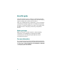
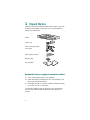
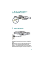
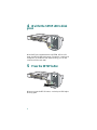
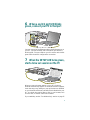
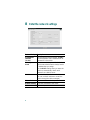
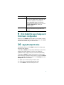
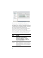
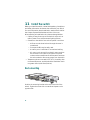
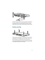
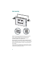
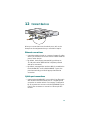
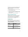
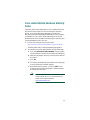
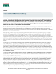
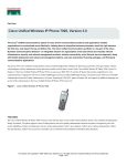
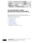
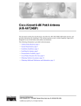
Getting Started Guide
Getting Started Guide for the
Catalyst Express 500 Switches
INCLUDING LICENSE AND WARRANTY
1X
2
1
4
3
5
6
7
8
9
10
11
12
11X
13X
12X
14X
13
14
15
16
17
18
19
2X
POWE
20
21
22
23
R OVER ETHE
RNET
24
23X
Cataly
24X
st Exp
res
s 500
25
25
26
SYSTEM
ALERT
PoE
26
SETUP
SERIES
About this guide
This guide explains how to configure a Catalyst Express 500
switch for the first time. Basic configuration involves assigning
network settings and a password to the switch.
After you complete the basic configuration, you can access the
internal device manager application to manage and customize
the switch. The device manager is an easy-to-use interface that
provides tools for configuring, monitoring, and problem
solving.
Before you begin
Before you power or install the switch, review the safety
information in the Regulatory Compliance and Safety
Information for the Catalyst Express 500 Switch that
accompanies this guide.
For more information
For complete information about installing and using the switch,
see the User Guide for the Catalyst Express 500 Switches online
at Cisco.com > Technical Support & Documentation > Switches
> Catalyst Express 500 Switches.
2
Quick tour
This illustration shows the Ethernet ports, LEDs, and other
features on the switch. To set up the switch, you use the SETUP
button, an Ethernet port, and the SYSTEM, SETUP, and port
LEDs.
The model shown is a Catalyst Express 500-24LC. Your switch
model might look slightly different.
AC power connector
Port LEDs
Security cable slot
side and rear panels
1X
1
2
4
3
5
6
7
8
9
10
11
12
11X
13X
12X
14X
13
14
15
16
17
18
19
2X
POWER
20
21
22
23
OVER
ETHER
NET
24
23X
Catalyst
24X
Express
500
SERIES
25
25
26
SYSTEM
ALERT
PoE
26
SETUP
Power over Ethernet
(PoE) ports supply up to
15.4 W per port
Fast Ethernet ports
Dual-purpose uplink ports:
SFP module and
10/100/1000BASE-T
Autonegotiate and auto-MDIX
enabled on all ports
Switch LEDs:
SYSTEM ALERT
PoE
SETUP
-
SYSTEM
ALERT
PoE
switch status
events detected
PoE status
setup mode
SETUP
SETUP button
3
1 Unpack the box
Verify that you have received the items shown here. If any item
is missing or damaged, contact your Cisco representative or
reseller for instructions.
1X
1
2
3
4
5
6
7
8
9
10
11
12
11X
13X
12X
14X
13
14
15
16
17
18
19
Switch
2X
POWER
20
21
22
23
OVER
ETHERNE
24
23X
T
Catalyst
24X
Express
500
SERIES
25
25
26
SYSTEM
ALERT
PoE
26
SETUP
Power cord
Rack-mounting brackets
and screws
Cable guide and screw
Mounting feet
n
tio
co a
is nt
C e
um
oc
D
n
d
ar
C
io
co at
is t
C en
um
oc
D
co
is
C
Documentation
Equipment that you supply to set up the switch:
1. A PC with Windows 2000 or XP installed.
2. A web browser (Internet Explorer 5.5, 6.0, Netscape 7.1 or
later) with JavaScript enabled.
3. A straight-through or crossover Category 5 Ethernet cable
to connect your PC to the switch.
You should disable any pop-up blockers or proxy settings in
your browser software and any wireless client running on
your PC.
4
2 Make sure that nothing is
connected to the switch
1X
2
1
4
3
5
6
7
8
9
10
11
12
11X
13X
12X
14X
13
14
15
16
17
18
19
2X
POWE
20
21
22
23
R OVER ETHER
NET
24
23X
Catalyst
24X
Express
500
SERIES
25
25
26
26
SYSTEM
ALERT
PoE
RPS
SETUP
3 Power the switch
Connect the AC power cord to the connector on the switch rear
panel. Next, connect the power cord plug to a grounded AC
outlet.
When the switch powers on, it begins the power-on self-test
(POST), a series of automatic tests that confirm proper
operation. POST lasts approximately 1 minute. During POST,
the port and SYSTEM LEDs blink. When POST completes, the
SYSTEM LED turns solid green.
5
4 Wait for the SETUP LED to blink
green
oE 4
1X
2
1
4
3
5
6
7
8
9
10
11
12
11X
13X
12X
14X
13
14
15
16
17
18
19
20
2X
POWE
21
22
23
R OVER ETHER
24
NET
23X
Cisco
24X
2960
series
+PoE-4
25
25
SYSTEM
ALERT
PoE
RPS
26
26
SETUP
SYSTEM
ALERT
PoE
SETUP
When POST has completed and the SYSTEM LED is solid
green, the SETUP LED blinks green. The switch is ready to be
configured. (If the SETUP LED stops blinking, you can still
continue with the next step.)
5 Press the SETUP button
oE 4
1X
2
1
4
3
5
6
7
8
9
10
11
12
11X
13X
12X
14X
13
14
15
16
17
18
19
2X
POWE
20
21
22
23
R OVER ETHER
NET
24
23X
Cisco
24X
2960
series
+PoE-4
25
25
26
26
SYSTEM
ALERT
PoE
RPS
SETUP
SYSTEM
ALERT
PoE
SETUP
When you press the SETUP button, a switch port LED begins
blinking green.
6
6 When a switch port LED blinks
green, connect your PC to that port
1X
2
1
4
3
5
6
7
8
9
10
11
12
1
2X
POWER
OVER
11X
13X
12X
14X
13
14
2
15
16
17
18
19
20
21
1X
ETHER
NET
22
23
24
3
23X
4
24X
Catalyst
Express
500
SERIES
25
25
SYSTEM
ALERT
PoE
RPS
26
26
SETUP
2X
POWE
R
ETHER
OVER
NET
Connect one end of the Ethernet cable to the Ethernet port on
your PC. Connect the other end to the switch port with the
blinking LED. The port LEDs on your PC and the switch blink
green while the switch configures the connection.
7 When the SETUP LED turns green,
start a browser session on the PC
1X
1
2
4
3
5
6
7
8
9
10
11
12
11X
13X
12X
14X
13
14
15
16
17
18
19
2X
POWER
20
21
22
23
OVER
ETHER
NET
24
23X
Catalyst
24X
Express
500
SERIES
25
25
26
SYSTEM
ALERT
PoE
26
SETUP
When you start a browser session on your PC, the set-up
window automatically appears. If the window does not appear,
check that any proxy settings or pop-up blockers are disabled
on your browser and that any wireless client is disabled on your
PC. You might also need to enter a URL in your browser, such
as cisco.com, or another well-known website.
If you need help, see the “Troubleshooting” section on page 17.
7
8 Enter the network settings
Network Settings Description
Management
Interface
(VLAN)
We recommend using the default, VLAN 1.
The management VLAN establishes an IP
connection to the switch.
IP Assignment
Mode
We recommend using the default, Static,
which means that the switch always has the
IP address that you assign.
Use the DHCP setting when you want the
switch to automatically obtain an IP
address from a DHCP server.
IP Address
Enter the IP address for the switch. (Later,
you can use the IP address to access the
switch through the device manager.)
Subnet Mask
Select a mask from the drop-down list.
Default Gateway Enter the IP address of the router.
Username
8
Enter a unique name.
Network Settings Description
Password
Enter a password. The password can be
from 1 to 25 alphanumeric characters, can
start with a number, is case sensitive,
allows embedded spaces, but does not
allow spaces at the beginning or end. In the
Confirm Password field, enter your
password again.
Optional Settings Enter a Host Name for the switch. The
date and time fields are populated from
your PC.
9 Click Submit to save changes and
finish basic configuration
When you click Submit, the information you entered is saved.
You have completed the initial switch setup. If you click Cancel,
the fields are cleared, and you can start over.
10 Apply Smartports roles
Immediately after you click Submit in Step 9, the Smartports
dialog window appears.
Click Yes and Submit to accept the predefined port roles. The
Smartports window appears. Here you can change the
predefined roles or apply new port roles as described below.
Click No and Submit to apply the Smartports roles yourself.
When the device manager window appears, locate the Contents
menu on the left side of the window. Click Configure and then
Smartports. Follow these steps:
1. Select a port role from the pull-down menu.
2. Click a port to apply the selected port role.
3. Click Submit to save the Smartports roles.
9
We recommend that you apply the Cisco Smartports roles now.
The ports are then correctly configured before they are
connected to devices. Smartports roles provide optimal
performance on port connections, including appropriate levels
of reliability, security, and availability. They also help prevent
many problems caused by port misconfigurations.
The only requirements are to decide and write down which
switch port will be connected to which device type.
You can connect a WAN device to any port. Apply the Router
port role for this type of connection. Use an uplink port to
connect to another switch and apply the Switch port role.
Smartports
Roles
Description
Desktop
Apply this role on switch ports connecting to
desktop devices, such as desktop PCs,
workstations, notebook PCs, and other
client-based hosts. Note: Do not apply the
Desktop role on ports that are connected to
routers or to other switches.
IP Phone+
Desktop
Apply this role on switch ports connecting to IP
phones. A desktop device, such as a PC, can be
connected to the IP phone. Both the IP phone and
connected PC would have access to the network
and the Internet.
10
Smartports
Roles
Description
Access
Point
Apply this role on switch ports connecting to
wireless access points (APs). Connected to the AP
are mobile devices, such as wireless laptop PCs.
Printer
Apply this role on switch ports connecting to a
printer, such as a network printer or an external
print server.
Guest
Apply this role on switch ports that are used by
guests and visitors. Guests have access to the
Internet but not access to your internal network.
You can connect an AP on this port to provide
guest wireless access.
Server
Apply this role on switch ports connecting to
servers that provide network services, such as
exchange servers, collaborative servers, terminal
servers, file servers, and DHCP servers.
Switch
Apply this role on switch ports connecting to
other switches.
Router
Apply this role on switch ports connecting to
WAN devices that connect to the Internet, such as
routers, firewalls, or virtual private network
concentrators.
Other
Apply this role on switch ports if you do not want
to assign a specialized role on the port.
If you need more information, click Help on the device manager
toolbar.
When you are finished, disconnect your PC from the switch to
end the session.
11
11 Install the switch
Before you install the switch, review the Regulatory Compliance
and Safety Information document that came with your switch.
For more information about installation, see the User Guide for
the Catalyst Express 500 Switches online at Cisco.com.
When selecting an installation site, observe these guidelines:
• Cabling is away from sources of electrical noise, such as
radios, power lines, and fluorescent lighting fixtures.
• Clearance to the switch front and rear panels is such that
– Airflow around the switch and through the vents is
unrestricted.
– Front-panel LEDs can be easily read.
– Access to ports is sufficient for unrestricted cabling.
– AC power cord can reach from the AC power outlet to
the connector on the switch rear panel. The power
outlet must be accessible at all time because it serves as
the main method to disconnect power from the switch.
• Temperature does not exceed 113˚F (45˚C), humidity does
not exceed 85 percent, and altitude at the installation site is
not greater than 10,000 feet (3049 m).
Rack-mounting
1X
2
1
4
3
5
6
7
8
9
10
11
12
11X
13X
12X
14X
13
14
15
16
17
18
19
2X
POWE
20
21
22
23
R OVER ETHER
NET
24
23X
Catalyst
24X
Express
500
SERIES
25
25
26
26
SYSTEM
ALERT
PoE
RPS
SETUP
Position the mounting bracket and screw on the side of the
switch. Tighten the screw with a screwdriver. Repeat on the
opposite side.
12
1X
2
1
4
3
5
6
7
8
9
10
11
12
11X
13X
12X
14X
13
14
15
16
17
18
19
20
2X
POWE
21
22
23
R OVER ETHER
NET
24
23X
Catalyst
Express
500 SERIE
S
25
24X
25
26
26
SYSTEM
ALERT
PoE
RPS
SETUP
Insert the switch into the 19-inch rack and align the bracket in
the rack. Use either the 10-32 pan-head screws, or the 12-24
pan-slotted screws to secure the switch in the rack. Use the
black Phillips screw to attach the cable guide to either bracket.
Desktop-mounting
SETUP
SYSTEM
ALERT
PoE
RPS
26
25
24X
12X
NET
2X
POWE
23
21
19
17
11X
11
9
7
5
3
1
ess 500
SERIES
23X
R OVER ETHER
1X
26
25
Catalyst
Expr
14X
13X
15
13
24
22
20
18
16
14
12
10
8
6
4
2
Place the switch upside-down on a flat surface. Attach the four
rubber pads to the recessed areas on the bottom of the switch.
Place the switch on a desktop near an AC power source.
If you are stacking switches, make sure that the mounting feet
of the upper switch align with the recesses of the lower switch.
Do not stack more than four units high.
13
25
2960
+PoE-4
OV
6
7
ETHER
NET
14X
12X
26
26
25
25
Cisco 2960
23X
1X
1
2
2X
POWER
OVER
3
4
ETHERNET
5
6
7
8
9
10
11
12
11X
13X
13
14
15
16
17
18
19
20
21
22
23
24
24X
series
+PoE-4
1X
1
2
3
2X
4
POWE
R
5
ER
8
9
10
11
12
X
11
X
13
13
14
X
12
15
X
14
16
17
18
19
20
21
22
23
24
X
23
X
24
25
Cisco
s
e
ri
e
s
26
26
Wall-mounting
Position the mounting bracket and screw on the side of the
switch, rotated 90-degrees from the view shown in the
rack-mounting illustration. Tighten the screw with a
screwdriver. Repeat on the opposite side.
Mount the switch on the wall with the front panel facing up. For
the best support of the switch and cables, make sure that the
switch is attached securely to wall studs or to a firmly attached
plywood mounting backboard. Screws for wall-mounting are
not provided.
If your switch has a redundant power supply (RPS) connector
on the rear panel, make sure that the cover plate is installed if
an RPS is not connected to the switch.
14
12 Connect devices
1X
2
1
4
3
5
6
7
8
9
10
11
12
11X
13X
13
14
15
16
17
8
2X
POWE
19
18
19
20
20
21
21
R OVER ETHER
NET
14X
22
23
22
23
12X
24
24
23X
Catalyst
23X
Cataly
25
24X
25
Express
26
26
24X
25
500
st Exp
ress 500
25
SYSTEM
ALERT
PoE
RPS
SERIES
SERI
SETUP
26
26
SYSTEM
ALERT
PoE
RPS
SETUP
When you connect devices to the switch ports, refer to the
Smartports role assignments that you recorded in Step 10.
Ethernet connections
• Use either straight-through or crossover Category 5 cables
with RJ-45 connectors to connect from the switch Ethernet
ports to other devices.
• By default, the PoE ports automatically provide up to
15.4 W power when IEEE 802.3af-compliant-powered
devices are connected.
• By default, autonegotiation and auto-MDIX are enabled on
the 10/100BASE-T and 10/100/1000BASE-T ports; the
ports automatically provide the appropriate Ethernet
connection.
Uplink port connections
• Use the 10/100/1000BASE-T port or add a Cisco fiber-optic
SFP module to the SFP module port for a Gigabit uplink
connection to another switch. Use Category 5 cables with
RJ-45 connectors to connect to a 10/100/1000BASE-T port.
Use LC fiber connectors to connect to a fiber-optic SFP
module.
15
• The dual-purpose uplink ports establish a link through
either the SFP module port or the 10/100/1000BASE-T
port, but not both at the same time. An SFP module port has
precedence over a 10/100/1000BASE-T port. If an SFP
module port has a link, that link is active. If the SFP port
does not have a link and the 10/100/1000BASE-T port
does, that link is active. Reselection occurs when the active
link is disconnected.
For a list of supported modules, see the Catalyst Express 500
Switch Release Notes on Cisco.com. For detailed instructions
on installing, removing, and connecting to SFP modules, see the
documentation that accompanied the module.
13 More information
This section includes information about the device manager,
troubleshooting, and the Cisco warranty terms.
How to access the device manager
16
The simplest way to configure, manage, and monitor the switch
is by using the device manager. You can access the device
manager from anywhere in your network through a web
browser. Follow these steps:
1. Set up and install the switch in your network, and connect
devices as described in this guide.
2. Launch a web browser on your PC.
3. Enter the switch IP address (the address that you assigned
in Step 8) in the web browser, and press Enter. The device
manager page appears.
4. To end the session, close your browser window.
About Cisco Network Assistant
Cisco Network Assistant is a free software program that you
download from Cisco.com and run on your PC. Network
Assistant offers advanced options for configuring and
monitoring multiple devices. Click Network Assistant on the
device manager menu for more information.
Troubleshooting
Help with the initial switch configuration is provided below. For
additional assistance, refer to the online documentation at
Cisco.com > Technical Support & Documentation > Switches >
Catalyst Express 500 Switches.
Checklist
Recommendation
Was the SETUP LED
blinking when you
pressed the SETUP
button?
If no, or you are not sure, restart
the switch. Make sure that the
SETUP LED is blinking when you
press the SETUP button.
Did you connect your PC Verify that you are connected to
to the wrong switch port? the switch port with the blinking
LED as shown in Step 6.
17
Checklist
Recommendation
Did you start a browser
session on your PC before
the SETUP LED was solid
green?
If yes, or you are not sure, restart
the switch. Perform Step 2
through Step 6. When the SETUP
LED is solid green, start a browser
session on your PC. Complete the
set-up procedure.
Did you start a browser
session on your PC and
the set-up page did not
appear?
If the window does not appear,
enter a URL in your browser, such
as cisco.com, or another
well-known website.
Did you have a pop-up
blocker running on your
PC when you connected
to the switch port?
If yes, disconnect the cable from
the switch port, disable the
pop-up blocker, and reconnect to
the switch. Press the SETUP
button to continue.
Did you have proxy
settings enabled in your
browser software when
you connected to the
switch port?
If yes, disconnect the cable from
the switch port, disable the proxy
settings, and reconnect to the
switch. Press the SETUP button to
continue.
Did you have a wireless
client running on your PC
when you connected to
the switch port?
If yes, disconnect the cable from
the switch port, disable the
wireless client, and reconnect to
the switch. Press the SETUP
button to continue.
Do you need to change
the switch IP address after
you have already
completed the initial
setup?
Go to the Configure > Express
Setup device manager screen to
change the switch IP address. For
more information about changing
the swith IP address, see the User
Guide for the Catalyst Express
500 Switches online at Cisco.com.
18
Cisco Limited Lifetime Hardware Warranty
Terms
There are special terms applicable to your hardware warranty
and various services that you can use during the warranty
period. Your formal Warranty Statement, including the
warranties and license agreements applicable to Cisco software,
is available on Cisco.com. Follow these steps to access and
download the Cisco Information Packet and your warranty and
license agreements from Cisco.com.
1. Launch your browser, and go to this URL:
http://www.cisco.com/univercd/cc/td/doc/es_inpck/cetrans.htm
The Warranties and License Agreements page appears.
2. To read the Cisco Information Packet, follow these steps:
a. Click the Information Packet Number field, and make
sure that the part number 78-5235-03A0 is highlighted.
b. Select the language in which you would like to read the
document.
c. Click Go.
d. The Cisco Limited Warranty and Software License page
from the Information Packet appears.
e. Read the document online, or click the PDF icon to
download and print the document in Adobe Portable
Document Format (PDF).
Note
You must have Adobe Acrobat Reader to view
and print PDF files. You can download the
reader from Adobe’s website:
http://www.adobe.com
19
3. To read translated and localized warranty information
about your product, follow these steps:
a. Enter this part number in the Warranty Document
Number field:
78-6310-02C0
b. Select the language in which you would like to view the
document.
c. Click Go.
The Cisco warranty page appears.
d. Read the document online, or click the PDF icon to
download and print the document in Adobe Portable
Document Format (PDF).
You can also contact the Cisco service and support website for
assistance:
http://www.cisco.com/public/Support_root.shtml.
Duration of Hardware Warranty
A Cisco product hardware warranty is supported for as long as
the original end user continues to own or use the product,
provided that the fan and power supply warranty is limited to
five (5) years. In the event of a discontinuance of product
manufacture, the Cisco warranty support is limited to five (5)
years from the announcement of the discontinuance.
Replacement, Repair, or Refund Policy for
Hardware
Cisco or its service center will use commercially reasonable
efforts to ship a replacement part within ten (10) working days
after receipt of the Return Materials Authorization (RMA)
request. Actual delivery times can vary, depending on the
customer location.
Cisco reserves the right to refund the purchase price as its
exclusive warranty remedy.
20
To Receive a Return Materials Authorization (RMA)
Number
Contact the company from whom you purchased the product. If
you purchased the product directly from Cisco, contact your
Cisco Sales and Service Representative.
Complete the information below, and keep it for reference.
Company product
purchased from
Company
telephone number
Product model
number
Product serial
number
Maintenance
contract number
21
22
23
Corporate Headquarters
Cisco Systems, Inc.
170 West Tasman Drive
San Jose, CA 95134-1706
USA
www.cisco.com
Tel: 408 526-4000
800 553-NETS (6387)
Fax: 408 526-4100
European Headquarters
Cisco Systems International BV
Haarlerbergpark
Haarlerbergweg 13-19
1101 CH Amsterdam
The Netherlands
www-europe.cisco.com
Tel: 31 0 20 357 1000
Fax: 31 0 20 357 1100
Americas Headquarters
Cisco Systems, Inc.
170 West Tasman Drive
San Jose, CA 95134-1706
USA
www.cisco.com
Tel: 408 526-7660
Fax: 408 527-0883
Asia Pacific Headquarters
Cisco Systems, Inc.
168 Robinson Road
#28-01 Capital Tower
Singapore 068912
www.cisco.com
Tel: +65 6317 7777
Fax: +65 6317 7799
Cisco Systems has more than 200 offices in the following countries. Addresses, phone numbers, and
fax numbers are listed on the
Cisco Website at www.cisco.com/go/offices
Argentina • Australia • Austria • Belgium • Brazil • Bulgaria • Canada • Chile • China PRC • Colombia • Costa Rica
Croatia • Cyprus • Czech Republic • Denmark • Dubai, UAE • Finland • France • Germany • Greece
Hong Kong SAR • Hungary • India • Indonesia • Ireland • Israel • Italy • Japan • Korea • Luxembourg
Malaysia • Mexico • The Netherlands • New Zealand • Norway • Peru • Philippines • Poland • Portugal • Puerto
Rico • Romania • Russia • Saudi Arabia • cotland • Singapore • Slovakia • Slovenia • South Africa • Spain • Sweden
Switzerland • Taiwan • Thailand • Turkey • Ukraine • United Kingdom • United States • Venezuela • Vietnam • Zimbabwe
CCSP, CCVP, the Cisco Square Bridge logo, Follow Me Browsing, and StackWise are trademarks of
Cisco Systems, Inc.; Changing the Way We Work, Live, Play, and Learn, and iQuick Study are service marks
of Cisco Systems, Inc.; and Access Registrar, Aironet, BPX, Catalyst, CCDA, CCDP, CCIE, CCIP, CCNA,
CCNP, Cisco, the Cisco Certified Internetwork Expert logo, Cisco IOS, Cisco Press, Cisco Systems,
Cisco Systems Capital, the Cisco Systems logo, Cisco Unity, Enterprise/Solver, EtherChannel, EtherFast,
EtherSwitch, Fast Step, FormShare, GigaDrive, GigaStack, HomeLink, Internet Quotient, IOS, IP/TV,
iQ Expertise, the iQ logo, iQ Net Readiness Scorecard, LightStream, Linksys, MeetingPlace, MGX,
the Networkers logo, Networking Academy, Network Registrar, Packet, PIX, Post-Routing, Pre-Routing,
ProConnect, RateMUX, ScriptShare, SlideCast, SMARTnet, The Fastest Way to Increase Your Internet
Quotient, and TransPath are registered trademarks of Cisco Systems, Inc. and/or its affiliates in the
United States and certain other countries.
All other trademarks mentioned in this document or Website are the property of their respective owners.
The use of the word partner does not imply a partnership relationship between Cisco and any other
company. (0601R)
© 2005 Cisco Systems, Inc. All rights reserved.
Printed in China PRC
78-17084-02
DOC-7817084=