1
Cisco Catalyst 4900M Switch
Installation Guide
January 2008
Americas Headquarters
Cisco Systems, Inc.
170 West Tasman Drive
San Jose, CA 95134-1706
USA
http://www.cisco.com
Tel: 408 526-4000
800 553-NETS (6387)
Fax: 408 527-0883
Text Part Number: 78-18350-01
THE SPECIFICATIONS AND INFORMATION REGARDING THE PRODUCTS IN THIS MANUAL ARE SUBJECT TO CHANGE WITHOUT
NOTICE. ALL STATEMENTS, INFORMATION, AND RECOMMENDATIONS IN THIS MANUAL ARE BELIEVED TO BE ACCURATE BUT
ARE PRESENTED WITHOUT WARRANTY OF ANY KIND, EXPRESS OR IMPLIED. USERS MUST TAKE FULL RESPONSIBILITY FOR
THEIR APPLICATION OF ANY PRODUCTS.
THE SOFTWARE LICENSE AND LIMITED WARRANTY FOR THE ACCOMPANYING PRODUCT ARE SET FORTH IN THE INFORMATION
PACKET THAT SHIPPED WITH THE PRODUCT AND ARE INCORPORATED HEREIN BY THIS REFERENCE. IF YOU ARE UNABLE TO
LOCATE THE SOFTWARE LICENSE OR LIMITED WARRANTY, CONTACT YOUR CISCO REPRESENTATIVE FOR A COPY.
The following information is for FCC compliance of Class A devices: This equipment has been tested and found to comply with the limits for a Class
A digital device, pursuant to part 15 of the FCC rules. These limits are designed to provide reasonable protection against harmful interference when
the equipment is operated in a commercial environment. This equipment generates, uses, and can radiate radio-frequency energy and, if not installed
and used in accordance with the instruction manual, may cause harmful interference to radio communications. Operation of this equipment in a
residential area is likely to cause harmful interference, in which case users will be required to correct the interference at their own expense.
The following information is for FCC compliance of Class B devices: The equipment described in this manual generates and may radiate
radio-frequency energy. If it is not installed in accordance with Cisco’s installation instructions, it may cause interference with radio and television
reception. This equipment has been tested and found to comply with the limits for a Class B digital device in accordance with the specifications in
part 15 of the FCC rules. These specifications are designed to provide reasonable protection against such interference in a residential installation.
However, there is no guarantee that interference will not occur in a particular installation.
Modifying the equipment without Cisco’s written authorization may result in the equipment no longer complying with FCC requirements for Class
A or Class B digital devices. In that event, your right to use the equipment may be limited by FCC regulations, and you may be required to correct
any interference to radio or television communications at your own expense.
You can determine whether your equipment is causing interference by turning it off. If the interference stops, it was probably caused by the Cisco
equipment or one of its peripheral devices. If the equipment causes interference to radio or television reception, try to correct the interference by
using one or more of the following measures:
• Turn the television or radio antenna until the interference stops.
• Move the equipment to one side or the other of the television or radio.
• Move the equipment farther away from the television or radio.
• Plug the equipment into an outlet that is on a different circuit from the television or radio. (That is, make certain the equipment and the television
or radio are on circuits controlled by different circuit breakers or fuses.)
Modifications to this product not authorized by Cisco Systems, Inc. could void the FCC approval and negate your authority to operate the product.
The Cisco implementation of TCP header compression is an adaptation of a program developed by the University of California, Berkeley (UCB) as
part of UCB’s public domain version of the UNIX operating system. All rights reserved. Copyright © 1981, Regents of the University of California.
NOTWITHSTANDING ANY OTHER WARRANTY HEREIN, ALL DOCUMENT FILES AND SOFTWARE OF THESE SUPPLIERS ARE
PROVIDED “AS IS” WITH ALL FAULTS. CISCO AND THE ABOVE-NAMED SUPPLIERS DISCLAIM ALL WARRANTIES, EXPRESSED
OR IMPLIED, INCLUDING, WITHOUT LIMITATION, THOSE OF MERCHANTABILITY, FITNESS FOR A PARTICULAR PURPOSE AND
NONINFRINGEMENT OR ARISING FROM A COURSE OF DEALING, USAGE, OR TRADE PRACTICE.
IN NO EVENT SHALL CISCO OR ITS SUPPLIERS BE LIABLE FOR ANY INDIRECT, SPECIAL, CONSEQUENTIAL, OR INCIDENTAL
DAMAGES, INCLUDING, WITHOUT LIMITATION, LOST PROFITS OR LOSS OR DAMAGE TO DATA ARISING OUT OF THE USE OR
INABILITY TO USE THIS MANUAL, EVEN IF CISCO OR ITS SUPPLIERS HAVE BEEN ADVISED OF THE POSSIBILITY OF SUCH
DAMAGES.
CCVP, the Cisco logo, and Welcome to the Human Network are trademarks of Cisco Systems, Inc.; Changing the Way We Work, Live, Play, and
Learn is a service mark of Cisco Systems, Inc.; and Access Registrar, Aironet, Catalyst, CCDA, CCDP, CCIE, CCIP, CCNA, CCNP, CCSP, Cisco,
the Cisco Certified Internetwork Expert logo, Cisco IOS, Cisco Press, Cisco Systems, Cisco Systems Capital, the Cisco Systems logo, Cisco Unity,
Enterprise/Solver, EtherChannel, EtherFast, EtherSwitch, Fast Step, Follow Me Browsing, FormShare, GigaDrive, HomeLink, Internet Quotient,
IOS, iPhone, IP/TV, iQ Expertise, the iQ logo, iQ Net Readiness Scorecard, iQuick Study, LightStream, Linksys, MeetingPlace, MGX, Networkers,
Networking Academy, Network Registrar, PIX, ProConnect, ScriptShare, SMARTnet, StackWise, The Fastest Way to Increase Your Internet
Quotient, and TransPath are registered trademarks of Cisco Systems, Inc. and/or its affiliates in the United States and certain other countries.
All other trademarks mentioned in this document or Website are the property of their respective owners. The use of the word partner does not imply
a partnership relationship between Cisco and any other company. (0711R)
Cisco Catalyst 4900M Switch Installation Guide
Copyright © 2008 Cisco Systems, Inc. All rights reserved.
C O N T E N T S
Preface ix
Audience ix
Organization ix
Related Documentation x
Conventions x
Statement 1071—Warning Definition xii
Obtaining Documentation, Obtaining Support, and Security Guidelines xx
CHAPTER
1
Product Overview 1-1
Catalyst 4900M Switch Applications 1-1
Catalyst 4900M Switch Software Features 1-6
Hardware System Features 1-6
Switch Components 1-7
Traffic Ports 1-7
TwinGig Modules 1-7
Rear Chassis Connections and Features 1-8
Front Panel LEDs 1-9
Chassis Cooling 1-11
Power Supplies 1-12
Environmental Monitoring of the Power Supplies 1-13
Power Management for the Catalyst 4900M Switch 1-13
Power Management Modes 1-14
Serial Number Location 1-15
Cisco Catalyst 4900M Switch Installation Guide
78-18350-01
v
Contents
CHAPTER
2
Site Planning 2-1
Site Environmental Requirements 2-1
Site Power Requirements 2-2
Preinstallation Requirements 2-3
Warnings and Cautions 2-3
EMI Recommendations 2-4
Power Requirements and Heat Dissipation 2-4
Grounding Requirements 2-4
Safety Overview 2-5
Ensuring Safety 2-5
Working Safely with Electricity 2-6
Preventing Electrostatic Discharge Damage 2-7
Site Planning Checklist 2-7
CHAPTER
3
Installing the Switch 3-1
Checking the Contents 3-1
Rack-Mounting the Switch 3-2
Rack-Mounting Guidelines 3-3
Lifting the Chassis Safely 3-4
Required Installation Tools 3-5
Rack-Mounting the Catalyst 4900M Switch 3-6
Connecting Power to the Catalyst 4900M Switch 3-11
Connecting DC Power to the Catalyst 4900M Switch 3-13
Optical Connections 3-15
Configurable Modules 3-15
Required Tools 3-16
Removing Switching Modules 3-16
Installing Switching Modules 3-19
Cisco Catalyst 4900M Switch Installation Guide
vi
78-18350-01
Contents
Removing and Replacing the Power Supply 3-22
Required Tools 3-23
Removing a Power Supply 3-23
Installing a Power Supply 3-24
Removing and Replacing the Fan Assembly 3-25
Required Tools 3-25
Removing the Fan Assembly 3-25
Installing the Fan Assembly 3-26
Verifying the Installation 3-27
CHAPTER
4
Troubleshooting the Installation 4-1
Getting Started 4-1
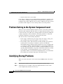
Problem Solving to the System Component Level 4-2
Identifying Startup Problems 4-2
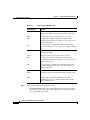
LED Readings 4-3
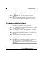
Troubleshooting the Power Supply 4-5
Contacting Customer Service 4-6
APPENDIX
A
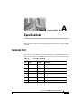
Specifications A-1
Console Port A-1
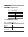
10/100/1000BASE-T Management Port A-2
Catalyst 4900M Switch Specifications A-2
APPENDIX
B
Compliance Information and Translated Safety Warnings B-1
Regulatory Standards Compliance B-1
European Directives B-4
Statement 275—Declaration of Conformity with Regard to the Directives
73/23/EEC and 89/336/EEC as amended by Directive 93/68/EEC B-4
EMC Class A Notices and Warnings B-6
Cisco Catalyst 4900M Switch Installation Guide
78-18350-01
vii
Contents
Class A Notice for FCC B-6
Class A Notice for Canada B-6
Statement 340—Class A Warning for CISPR22 B-7
Statement 191—VCCI Class A Warning for Japan B-9
Statement 256—Class A Warning for Hungary B-10
Statement 294—Class A Warning for Korea B-10
Statement 257—Class A Notice for Taiwan and Other Traditional Chinese
Markets B-11
Statement 371—Power Cable and AC Adapter B-11
Translated Safety Warnings B-11
Statement 258—Fan Tray Removal Warning B-12
Statement 1003—DC Power Disconnection B-14
Statement 1004—Installation Instructions B-15
Statement 1006—Chassis Warning for Rack-Mounting and Servicing B-18
Statement 1008—Class 1 Laser Product B-26
Statement 1011—Staring into Laser Beam B-28
Statement 1017—Restricted Area B-30
Statement 1019—Main Disconnecting Device B-33
Statement 1024—Ground Conductor B-35
Statement 1028—More Than One Power Supply B-37
Statement 1029—Blank Faceplates and Cover Panels B-40
Statement 1030—Equipment Installation B-45
Statement 1040—Product Disposal B-47
Statement 1045—Short-Circuit Protection B-50
Statement 1051—Laser Radiation B-53
Statement 1072—Shock Hazard from Interconnections B-56
Statement 1074—Comply with Local and National Electrical Codes B-60
Statement 1075—Hazardous Voltage or Energy Present on DC Power
Terminals B-61
INDEX
Cisco Catalyst 4900M Switch Installation Guide
viii
78-18350-01
Preface
This preface describes the audience, organization, and conventions of the Cisco
Catalyst 4900M Switch Installation Guide and provides information on how to
obtain related documentation.
Audience
Only trained and qualified service personnel (as defined in IEC60950 and
AZ/NZS 60950) should install, replace, or service the equipment.
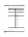
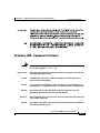
Organization
This guide is organized as follows:
Chapter
Title
Description
Chapter 1
Product Overview
Describes the hardware features and functionality of the
Catalyst 4900M switch.
Chapter 2
Site Planning
Describes how to prepare your site for the installation of the
switch.
Chapter 3
Installing the Switch Details how to install the Catalyst 4900M switch.
Chapter 4
Troubleshooting the
Installation
Provides troubleshooting guidelines for the initial hardware
installation and suggests steps to help isolate and resolve
problems.
Cisco Catalyst 4900M Switch Installation Guide
78-18350-01
ix
Preface
Chapter
Title
Description
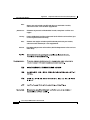
Appendix A
Specifications
Lists the Catalyst 4900M switch system specifications.
Appendix B
Translated Safety
Warnings
Repeats in multiple languages the warnings in this guide.
Related Documentation
Refer to the following documents for additional information about configuring the
Catalyst 4900M switch:
•
Software Configuration Guide—Catalyst 4500 Series.
•
Command Reference—Catalyst 4500 Series.
•
System Message Guide—Catalyst 4500 Series.
The Catalyst 4900M switch uses software that also runs on the Catalyst 4500
series switches. Refer to the version of these documents appropriate for your
software.
Conventions
This docum entuses the follow ing conventions:
Convention
Description
boldface font
Com m ands and keyw ords are in boldface.
italic font
A rgum ents forw hich you supply values are in italics.
[ ]
Elem ents in square brackets are optional.
{ x |y |z }
A lternative keyw ords are grouped in braces and
separated by verticalbars.
[x |y |z ]
O ptionalalternative keyw ords are grouped in brackets
and separated by verticalbars.
string
A non-quoted setofcharacters.D o notuse quotation
m arks around the string,because the string w illinclude
the quotation m arks.
Cisco Catalyst 4900M Switch Installation Guide
x
78-18350-01
Preface
Convention
screen
font
boldface screen
font
italic screen font
Description
Term inalsessions and inform ation thatthe system
displays are in screen font.
Inform ation thatyou m ustenteris show n in boldface
font.
screen
A rgum ents forw hich you supply values are in italic
font.
screen
Ctrl-
Ctrl-represents the key labeled Control— forexam ple,
the key com bination C trl-D m eans to hold dow n the
Controlkey w hile you press the D key.
< >
Characters thatdo notprint,such as passw ords,are
show n w ithin angle brackets.
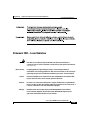
Notes use the following conventions:
Note
Means reader take note. Notes contain helpful suggestions or references to
material not covered in the publication.
Cautions use the following conventions:
Caution
Means reader be careful. In this situation, you might do something that could
result in equipment damage or loss of data.
Cisco Catalyst 4900M Switch Installation Guide
78-18350-01
xi
Preface
Warnings use the following conventions:
Statement 1071—Warning Definition
Warning
IMPORTANT SAFETY INSTRUCTIONS
This warning symbol means danger. You are in a situation that could cause
bodily injury. Before you work on any equipment, be aware of the hazards
involved with electrical circuitry and be familiar with standard practices for
preventing accidents. Use the statement number provided at the end of each
warning to locate its translation in the translated safety warnings that
accompanied this device. Statement 1071
SAVE THESE INSTRUCTIONS
Waarschuwing
BELANGRIJKE VEILIGHEIDSINSTRUCTIES
Dit waarschuwingssymbool betekent gevaar. U verkeert in een situatie die
lichamelijk letsel kan veroorzaken. Voordat u aan enige apparatuur gaat
werken, dient u zich bewust te zijn van de bij elektrische schakelingen
betrokken risico's en dient u op de hoogte te zijn van de standaard praktijken
om ongelukken te voorkomen. Gebruik het nummer van de verklaring
onderaan de waarschuwing als u een vertaling van de waarschuwing die bij
het apparaat wordt geleverd, wilt raadplegen.
BEWAAR DEZE INSTRUCTIES
Varoitus
TÄRKEITÄ TURVALLISUUSOHJEITA
Tämä varoitusmerkki merkitsee vaaraa. Tilanne voi aiheuttaa ruumiillisia
vammoja. Ennen kuin käsittelet laitteistoa, huomioi sähköpiirien
käsittelemiseen liittyvät riskit ja tutustu onnettomuuksien yleisiin
ehkäisytapoihin. Turvallisuusvaroitusten käännökset löytyvät laitteen
mukana toimitettujen käännettyjen turvallisuusvaroitusten joukosta
varoitusten lopussa näkyvien lausuntonumeroiden avulla.
SÄILYTÄ NÄMÄ OHJEET
Cisco Catalyst 4900M Switch Installation Guide
xii
78-18350-01
Preface
Attention
IMPORTANTES INFORMATIONS DE SÉCURITÉ
Ce symbole d'avertissement indique un danger. Vous vous trouvez dans une
situation pouvant entraîner des blessures ou des dommages corporels. Avant
de travailler sur un équipement, soyez conscient des dangers liés aux circuits
électriques et familiarisez-vous avec les procédures couramment utilisées
pour éviter les accidents. Pour prendre connaissance des traductions des
avertissements figurant dans les consignes de sécurité traduites qui
accompagnent cet appareil, référez-vous au numéro de l'instruction situé à la
fin de chaque avertissement.
CONSERVEZ CES INFORMATIONS
Warnung
WICHTIGE SICHERHEITSHINWEISE
Dieses Warnsymbol bedeutet Gefahr. Sie befinden sich in einer Situation, die
zu Verletzungen führen kann. Machen Sie sich vor der Arbeit mit Geräten mit
den Gefahren elektrischer Schaltungen und den üblichen Verfahren zur
Vorbeugung vor Unfällen vertraut. Suchen Sie mit der am Ende jeder Warnung
angegebenen Anweisungsnummer nach der jeweiligen Übersetzung in den
übersetzten Sicherheitshinweisen, die zusammen mit diesem Gerät
ausgeliefert wurden.
BEWAHREN SIE DIESE HINWEISE GUT AUF.
Avvertenza
IMPORTANTI ISTRUZIONI SULLA SICUREZZA
Questo simbolo di avvertenza indica un pericolo. La situazione potrebbe
causare infortuni alle persone. Prima di intervenire su qualsiasi
apparecchiatura, occorre essere al corrente dei pericoli relativi ai circuiti
elettrici e conoscere le procedure standard per la prevenzione di incidenti.
Utilizzare il numero di istruzione presente alla fine di ciascuna avvertenza per
individuare le traduzioni delle avvertenze riportate in questo documento.
CONSERVARE QUESTE ISTRUZIONI
Cisco Catalyst 4900M Switch Installation Guide
78-18350-01
xiii
Preface
Advarsel
VIKTIGE SIKKERHETSINSTRUKSJONER
Dette advarselssymbolet betyr fare. Du er i en situasjon som kan føre til skade
på person. Før du begynner å arbeide med noe av utstyret, må du være
oppmerksom på farene forbundet med elektriske kretser, og kjenne til
standardprosedyrer for å forhindre ulykker. Bruk nummeret i slutten av hver
advarsel for å finne oversettelsen i de oversatte sikkerhetsadvarslene som
fulgte med denne enheten.
TA VARE PÅ DISSE INSTRUKSJONENE
Aviso
INSTRUÇÕES IMPORTANTES DE SEGURANÇA
Este símbolo de aviso significa perigo. Você está em uma situação que poderá
ser causadora de lesões corporais. Antes de iniciar a utilização de qualquer
equipamento, tenha conhecimento dos perigos envolvidos no manuseio de
circuitos elétricos e familiarize-se com as práticas habituais de prevenção de
acidentes. Utilize o número da instrução fornecido ao final de cada aviso para
localizar sua tradução nos avisos de segurança traduzidos que acompanham
este dispositivo.
GUARDE ESTAS INSTRUÇÕES
¡Advertencia!
INSTRUCCIONES IMPORTANTES DE SEGURIDAD
Este símbolo de aviso indica peligro. Existe riesgo para su integridad física.
Antes de manipular cualquier equipo, considere los riesgos de la corriente
eléctrica y familiarícese con los procedimientos estándar de prevención de
accidentes. Al final de cada advertencia encontrará el número que le ayudará
a encontrar el texto traducido en el apartado de traducciones que acompaña
a este dispositivo.
GUARDE ESTAS INSTRUCCIONES
Cisco Catalyst 4900M Switch Installation Guide
xiv
78-18350-01
Preface
Varning!
VIKTIGA SÄKERHETSANVISNINGAR
Denna varningssignal signalerar fara. Du befinner dig i en situation som kan
leda till personskada. Innan du utför arbete på någon utrustning måste du vara
medveten om farorna med elkretsar och känna till vanliga förfaranden för att
förebygga olyckor. Använd det nummer som finns i slutet av varje varning för
att hitta dess översättning i de översatta säkerhetsvarningar som medföljer
denna anordning.
SPARA DESSA ANVISNINGAR
Cisco Catalyst 4900M Switch Installation Guide
78-18350-01
xv
Preface
Aviso
INSTRUÇÕES IMPORTANTES DE SEGURANÇA
Este símbolo de aviso significa perigo. Você se encontra em uma situação em
que há risco de lesões corporais. Antes de trabalhar com qualquer
equipamento, esteja ciente dos riscos que envolvem os circuitos elétricos e
familiarize-se com as práticas padrão de prevenção de acidentes. Use o
número da declaração fornecido ao final de cada aviso para localizar sua
tradução nos avisos de segurança traduzidos que acompanham o dispositivo.
GUARDE ESTAS INSTRUÇÕES
Cisco Catalyst 4900M Switch Installation Guide
xvi
78-18350-01
Preface
Advarsel
VIGTIGE SIKKERHEDSANVISNINGER
Dette advarselssymbol betyder fare. Du befinder dig i en situation med risiko
for legemesbeskadigelse. Før du begynder arbejde på udstyr, skal du være
opmærksom på de involverede risici, der er ved elektriske kredsløb, og du
skal sætte dig ind i standardprocedurer til undgåelse af ulykker. Brug
erklæringsnummeret efter hver advarsel for at finde oversættelsen i de
oversatte advarsler, der fulgte med denne enhed.
GEM DISSE ANVISNINGER
Cisco Catalyst 4900M Switch Installation Guide
78-18350-01
xvii
Preface
Cisco Catalyst 4900M Switch Installation Guide
xviii
78-18350-01
Preface
Cisco Catalyst 4900M Switch Installation Guide
78-18350-01
xix
Preface
Obtaining Documentation, Obtaining Support, and
Security Guidelines
For information on obtaining documentation, obtaining support, providing
documentation feedback, security guidelines, and also recommended aliases and
general Cisco documents, see the monthly What’s New in Cisco Product
Documentation, which also lists all new and revised Cisco technical
documentation, at:
http://www.cisco.com/en/US/docs/general/whatsnew/whatsnew.html
Cisco Catalyst 4900M Switch Installation Guide
xx
78-18350-01
CH A P T E R
1
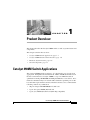
Product Overview
This chapter describes the Catalyst 4900M switch, as well as system features and
components.
This chapter contains these sections:
•
Catalyst 4900M Switch Applications, page 1-1
•
Catalyst 4900M Switch Software Features, page 1-6
•
Hardware System Features, page 1-6
•
Switch Components, page 1-7
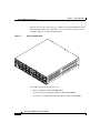
Catalyst 4900M Switch Applications
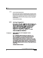
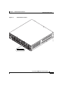
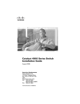
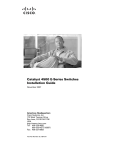
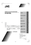
The Catalyst 4900M switch (see Figure 1-1) is designed for top-of-rack server
aggregation. It simplifies the transition from 1 GB to 10 GB attached devices in
the data center. The Cisco Catalyst 4900M is a top of rack Ethernet switch
optimized for mixing 10/100/1000 and 10 Gigabit Ethernet access devices. It is a
fixed Cisco IOS based Layer 2+ switch with 8 fixed wire speed X2 ports on the
base unit with 2 optional half card slots. The half card slots can accommodate the
following cards in any combination:
•
20-port wirespeed10/100/1000 (RJ-45) half card
•
4-port wire speed 10GbE (X2) half card
•
8-port (2:1) 10GbE (X2) half card (Twin Gig compatible)
Cisco Catalyst 4900M Switch Installation Guide
78-18350-01
1-1
Chapter 1
Product Overview
Catalyst 4900M Switch Applications
The half cards provide a wide variety of combinations of Gigabit Ethernet and 10
Gigabit Ethernet media types. The half slots also provide investment protection
for further additions of 1 GE and 10 GE media.
Catalyst 4900M Switch
232121
Figure 1-1
The modules that fit into the open slots are:
•
20-port 1 GE RJ-45 (WS-X4920-GB-RJ45=)
•
4-port X2 wire speed 10 Gigabit Ethernet (WS-X4904-10GE=)
•
8-port X2 2:1 oversubscribed 10 Gigabit Ethernet (WS-X4908-10GE=)
Cisco Catalyst 4900M Switch Installation Guide
1-2
78-18350-01
Chapter 1
Product Overview
Catalyst 4900M Switch Applications
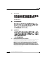
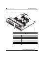
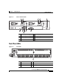
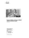
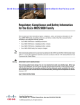
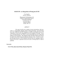
Figure 1-2
20-Port 1 GE RJ-45 (WS-X4920-GB-RJ45=)
1
1
232118
2
2
Module Status LED
Port LEDs
Specification
Description
Module type
10/100/1000BASE-T Fast Ethernet switching module
Port duplex mode
Half or full duplex mode
Port speed
10, 100, or 1000 Mbps
Number of ports
20
Connector type
RJ-45
Cable type
Category 5
Power over Ethernet
Not supported
Cisco Catalyst 4900M Switch Installation Guide
78-18350-01
1-3
Chapter 1
Product Overview
Catalyst 4900M Switch Applications
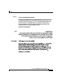
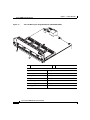
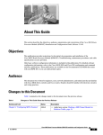
4-Port X2 Wire Speed 10 Gigabit Ethernet (WS-X4904-10GE=)
232119
Figure 1-3
1
2
1
2
Module Status LED
Port LEDs
Specification
Description
Module type
10 Gigabit X2 fiber Ethernet switching module
Port duplex mode
Full duplex mode
Port speed
10 Gbps
Number of ports
4
Connector type
SC type
Cable type
MMF or SMF
Cisco Catalyst 4900M Switch Installation Guide
1-4
78-18350-01
Chapter 1
Product Overview
Catalyst 4900M Switch Applications
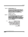
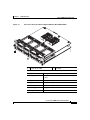
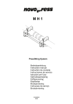
8-Port X2 2:1 Oversubscribed 10 Gigabit Ethernet (WS-X4908-10GE=)
232120
Figure 1-4
1
2
1
2
Module Status LED
Port LEDs
Specification
Description
Module type
10 Gigabit X2 or TwinGig fiber Ethernet switching
module
Port duplex mode
Full duplex mode
Port speed
10 Gbps or 2 Gbps
Number of ports
8
Connector type
SC type
Cable type
MMF or SMF
Cisco Catalyst 4900M Switch Installation Guide
78-18350-01
1-5
Chapter 1
Product Overview
Catalyst 4900M Switch Software Features
Note
When using TwinGig and X2 transceivers on this module, keep them grouped in
pairs as follows: 1-2, 3-4, 5-6, 7-8. Inserting a TwinGig or X2 transciever in any
port will affect the capabilities of its partner port, and both will be set to handle
the same type automatically. Mixing within a port group will not work. As an
example, you would not be able to have an X2 in port 1 and a TwinGig in port 2
and expect both of them to function.
The Catalyst 4900M switch has a 320-Gbps, nonblocking, full-duplex switching
fabric, providing 250 million packets-per-second of switching capacity for
high-speed applications. The Catalyst 4900M chassis has eight 10 Gigabit
Ethernet ports and other ports as configured.
A removable automatic variable speed fan tray for low-noise operation at room
temperature and removable and redundant 1000 W AC or 1000 W DC power
supplies provide fault-tolerance protection for the switch. See the “Connecting
Power to the Catalyst 4900M Switch” section on page 3-11.
Catalyst 4900M Switch Software Features
For up-to-date information on software features, refer to the release notes and
software configuration guide for your software release.
Hardware System Features
The Catalyst 4900M switch is a high-performance dedicated Ethernet switch that
fully integrates into the Catalyst family of switches using Catalyst 4500 series
system software.
The following is an overview of the Catalyst 4900M hardware features:
•
Eight 10 Gigabit Ethernet uplink ports using X2 interfaces
•
Serial console management port using an RJ-45 interface
•
A removable automatic variable speed fan tray for low-noise operation at
room temperature
•
Redundant and removable 1000 W AC or DC power supplies
Cisco Catalyst 4900M Switch Installation Guide
1-6
78-18350-01
Chapter 1
Product Overview
Switch Components
•
512-MB SDRAM (fixed)
•
128-MB embedded Flash memory
•
360-Gbps switching capacity, 250 million packets-per-second actual
forwarding rate
•
EtherChannel at 10/100/1000 Mbps, as well as 10 Gbps
•
Host and device USB 2.0 ports
•
Compact flash memory slot
Switch Components
This section describes the Catalyst 4900M hardware components.
Traffic Ports
There are eight 10-Gigabit Ethernet uplink ports using X2 interfaces and other
traffic ports depending on the switching modules installed.
TwinGig Modules
On the WS-4908-10GE modules only, TwinGig converter modules may be used
in place of X2 modules if you need to provide 1 GB SFP connections. When you
insert the TwinGig into one port, its neighbor automatically converts to 1 GE
interfaces whether it has a TwinGig installed or not, so you need to group your
TwinGigs next to one another. The neighboring port to a TwinGig port cannot
support an X2.
Installation documentation for Cisco TwinGig converter modules can be found at:
http://www.cisco.com/en/US/docs/switches/lan/catalyst3750e_3560e/hardware/i
nstall/notes/1757202.html
Cisco Catalyst 4900M Switch Installation Guide
78-18350-01
1-7
Chapter 1
Product Overview
Switch Components
Rear Chassis Connections and Features
The Reset button is used to restart the switch. Use a paper clip or other small,
pointed object to press the Reset button.
A console serial port (RJ-45) provides for switch management using standard
console equipment. (See Figure 1-5.) A connector pinout table is provided in
Appendix A, “Specifications,” for the console and management ports.
The Management port on the rear panel offers the same TCP/IP based
management services available via inband access (telnet SNMP etc.). IP address
configuration via BOOTP is supported on the Management port; it also supports
image download to the switch.
A USB connector is provided for future expansion.
The Compact Flash port accepts both 64-MB and 128-MB Type 1 compact Flash
cards. You can use it for file transfer tasks such as loading a new software image.
The Flash card is optional and can be obtained from third-party suppliers.
For more information, refer to Using the Compact Flash on the Catalyst 4500
Series Supervisor Engines at the following URL:
http://www.cisco.com/en/US/docs/switches/lan/catalyst4500/hardware/configura
tion/notes/OL_2788.html
Cisco Catalyst 4900M Switch Installation Guide
1-8
78-18350-01
Chapter 1
Product Overview
Switch Components
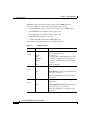
Figure 1-5
View of the Rear Panel
2
1
2
3
232122
1
4
5
7
8
6
1
Input OK (power supply)
5
Console port
2
Output OK (power supply)
6
Management port
3
Fan Status LED
7
USB connection
4
Reset button
8
Compact Flash slot
Front Panel LEDs
Figure 1-6
4
1
3
5
1
PS1 LED
4
System LED
2
PS2 LED
5
10Gig port LEDs
3
Fan LED
232123
2
Front LEDs
Cisco Catalyst 4900M Switch Installation Guide
78-18350-01
1-9
Chapter 1
Product Overview
Switch Components
The LEDs on the front and rear panel of the Catalyst 4900M switch (see
Figure 1-5 and Figure 1-6 ) provide status information as follows:
•
System LED indicates the operating state of the Catalyst 4900M switch.
•
PS1 LED indicates the internal power supply status.
•
PS2 LED indicates the internal power supply status.
•
FAN LED indicates the fan tray status.
•
A link status LED is below the 10-GB uplink ports.
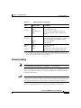
A description of the LED functions is provided in Table 1-1.
Table 1-1
LED
LED Descriptions
Color or State
Description
Green
Red
Flashing
Yellow
At startup, the Catalyst 4900M performs a
series of diagnostic tests:
All tests pass
A test other than an individual port test fails
System boot or diagnostic tests in progress
System is in rommon mode or a power supply
has failed
Switch is disabled
System
(front)
Off
CON
Green
10/100 BASE-T console port is in link-up
state
Off
10/100 BASE-T console port is in link-down
state or not connected
(rear)
There are no blinking, red, or yellow states
for this port
MGT
Green
10/100/1000BASE-T Management port is in
link-up state
Off
10/100/1000BASE-T Management port is in
link-down state or not connected
(rear)
There are no blinking, red, or yellow states
for this port
Cisco Catalyst 4900M Switch Installation Guide
1-10
78-18350-01
Chapter 1
Product Overview
Switch Components
Table 1-1
LED Descriptions (continued)
LED
Color or State
Description
Port
Green
Yellow
Flashing yellow
Off
Port is operational
Port is disabled by user
Power-on self-test indicates faulty port
No signal detected or link configuration
failure
Off
No power to the switch or fans (the tray may
not be plugged in especially if one or more of
the power supplies status LED is green)
Fan tray operational
Fault detected
(front)
Fan (front
and rear)
Green
Red
PS1 and
PS2
(front)
Off
Green
Red
No power to the PS
Operational1
Fault detected or the on/off switch is set to
off while the power supply is plugged in
1. If either LED is green and the other is OFF the power supply is probably not plugged in. If it is
red, the supply is either plugged in and not switched on or it is faulty. It may be necessary to
interrogate the system for further status using the CLI.
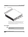
Chassis Cooling
Note
For environmental specifications, see Chapter 2, “Site Planning.”
The hot-swappable system fan tray provides cooling air for the internal chassis
components. The fans exhaust air to the left, and fresh air is drawn in from the
right side of the chassis.
Caution
When the fan tray is removed, internal circuitry is exposed that should not be
touched by tools or fingers. The system should not be left operating without a fan
tray for longer than is necessary to replace a faulty fan tray with a new one.
Figure 1-7 shows the direction of airflow going in and out of the switch.
Cisco Catalyst 4900M Switch Installation Guide
78-18350-01
1-11
Chapter 1
Product Overview
Switch Components
Catalyst 4900M Airflow
232124
Figure 1-7
There are five fans in the fan tray. If an individual fan fails, the other fans continue
to run. Sensors monitor the internal air temperatures. The number of fans in
operation and their speed varies according to the internal temperature for the
quietest operation possible. If the air temperature exceeds a desired threshold, the
environmental monitor displays warning messages.
Power Supplies
Note
For complete power specifications for the Catalyst 4900M switch, see
Appendix A, “Specifications.”
Cisco Catalyst 4900M Switch Installation Guide
1-12
78-18350-01
Chapter 1
Product Overview
Switch Components
The Catalyst 4900M switch has two redundant internal 1000 W AC or
1000 W DC power supplies.
The internal power supplies have individual power cords and status LEDs (PS1
and PS2 on the front panel). There are also LEDs on the power supplies that show
status for the input (Input OK) and output (Output OK) currents. A power cord is
used to connect the power supplies to the site AC power source. There is a power
switch on the AC Catalyst 4900M switch power supplies; AC power is present
when a power cord is plugged into a power supply and the switch is set to the On
position. DC power supplies do not use a power supply cord or have an on/off
switch.
The switch starts with only one power supply plugged in, but redundant failover
and load sharing is not available in this configuration. Cisco recommends that you
always connect both power supplies to separate AC or DC circuits for optimal
power reliability.
For safety reasons, the AC power supply must be switched off and unplugged
before it is removed from a chassis or inserted into a chassis. DC supplies should
have power shut off from the source before they are removed.
If only one power supply is used, you must use the blank faceplate supplied to
cover the empty power bay.
Environmental Monitoring of the Power Supplies
Using the environmental monitoring and reporting functions, you can maintain
normal system operation by resolving adverse environmental conditions prior to
loss of operation.
Each power supply monitors its own temperature and output voltages. The
Catalyst 4900M switch senses the operating condition of the power supply and
reports status through software.
Power Management for the Catalyst 4900M Switch
You can select AC or DC power supplies for your switch. The Catalyst 4900M
switch supports the following power supplies:
•
1000 W AC
•
1000 W DC
Cisco Catalyst 4900M Switch Installation Guide
78-18350-01
1-13
Chapter 1
Product Overview
Switch Components
A redundant power supply can be identified and diagnosed by a running system
regardless of its input status. AC and DC supplies are interchangeable.
Power Management Modes
The Catalyst 4900M switch supports the redundant power management mode. In
this mode, if both power supplies are operating normally, each provides from
20/80 to 45/55 percent of the total system power requirements at all times. If one
power supply fails, the other unit increases power to 100 percent of the total power
requirement.
Cisco Catalyst 4900M Switch Installation Guide
1-14
78-18350-01
Chapter 1
Product Overview
Serial Number Location
Serial Number Location
Figure 1-8 shows the location of the serial number for your switch.
Catalyst 4900M Serial Number
202519
Figure 1-8
SN: XXXNNNNXXXX
Cisco Catalyst 4900M Switch Installation Guide
78-18350-01
1-15
Chapter 1
Product Overview
Serial Number Location
Cisco Catalyst 4900M Switch Installation Guide
1-16
78-18350-01
CH A P T E R
2
Site Planning
This chapter describes how to prepare your site for installation of the
Catalyst 4900M switch and contains these sections:
Note
•
Site Environmental Requirements, page 2-1
•
Site Power Requirements, page 2-2
•
Grounding Requirements, page 2-4
•
Safety Overview, page 2-5
•
Site Planning Checklist, page 2-7
A site planning checklist is provided on page 2-8 to help ensure that you complete
all site planning activities before you install the switch.
Site Environmental Requirements
Planning a proper location for the switch and layout for your equipment rack or
wiring closet is essential for successful system operation. You should install the
switch in an enclosed, secure area, ensuring that only qualified personnel have
access to the switch and control of the environment. Equipment that is placed too
closely together or that is inadequately ventilated can cause system
overtemperature conditions. In addition, poor equipment placement can make
chassis panels inaccessible and difficult to maintain.
Cisco Catalyst 4900M Switch Installation Guide
78-18350-01
2-1
Chapter 2
Site Planning
Site Power Requirements
The switch operates as a standalone system mounted in a rack in a secure wiring
closet. It requires a dry, clean, well-ventilated, and air-conditioned environment.
To ensure normal operation, maintain ambient airflow. If the airflow is blocked or
restricted, or if the intake air is too warm, an overtemperature condition can occur.
The switch environmental monitor can then shut down the system to protect the
system components.
To ensure normal operation and avoid unnecessary maintenance, plan your site
configuration and prepare your site before installation. After installation, make
sure that the site maintains an ambient temperature of 0 to 40° C (32 to 104° F). It
is essential to keep the area around the chassis as free from dust and foreign
conductive material (such as metal flakes from nearby construction activity) as is
possible.
Multiple switches can be rack-mounted with little or no clearance above and
below the chassis. However, when mounting a switch in a rack with other
equipment, or when placing it on the floor near other equipment, ensure that the
exhaust from other equipment does not blow into the intake vents of the chassis.
Cooling air is drawn in through the right side and exhausted through the left side
of the chassis. Keep the sides and rear clear of obstructions, including dust and
foreign conductive material, and away from the exhaust ports of other equipment.
Appendix A, “Specifications,” lists the operating and nonoperating environmental
site requirements for the switches. To maintain normal operation and ensure high
system availability, maintain an ambient temperature and EMI-free and
continuous power at your site. The environmental ranges listed in Appendix A are
those within which the switch will continue to operate; however, a measurement
that approaches the minimum or maximum of a range indicates a potential
problem. You can maintain normal operation by anticipating and correcting
environmental anomalies before they exceed the maximum operating range.
Site Power Requirements
This section describes the installation site power requirements for the
Catalyst 4900M switch. Verify your site power before you install the switch.
This section consists of the following sections:
•
Preinstallation Requirements, page 2-3
•
Warnings and Cautions, page 2-3
Cisco Catalyst 4900M Switch Installation Guide
2-2
78-18350-01
Chapter 2
Site Planning
Site Power Requirements
•
EMI Recommendations, page 2-4
•
Power Requirements and Heat Dissipation, page 2-4
Preinstallation Requirements
Follow these requirements when preparing your site for the Catalyst 4900M
switch installation:
•
Connect each switch to separate wiring on a dedicated circuit; provide each
switch with its own branch circuit connection with sufficient overcurrent
protection and direct grounding to the branch circuit.
•
To prevent a loss of input power, be sure the total maximum load on each AC
circuit is within the current ratings of the wiring and breakers.
Warnings and Cautions
Follow these precautions when preparing your site for the Catalyst 4900M switch
installation:
Caution
The total maximum load on each AC or DC -input power circuit must be within
the rating of the wiring and breaker. An overload of input power can result if this
requirement is not met.
Warning
Read the installation instructions before connecting the system to the power
source. Statement 1004
Warning
Installation of the equipment must comply with local and national electrical
codes. Statement 1074
Warning
Ultimate disposal of this product should be handled according to all national
laws and regulations. Statement 1040
Cisco Catalyst 4900M Switch Installation Guide
78-18350-01
2-3
Chapter 2
Site Planning
Grounding Requirements
EMI Recommendations
Follow these guidelines when setting up the site wiring. When planning the
location of the new system, consider electromagnetic interface (EMI), the
distance limitations for signaling, and connector compatibility.
When wires are run for any significant distance in an electromagnetic field, radio
frequency interference (RFI) can occur between the field and the signals on the
wires.
Note
•
Bad plant wiring can result in radio frequency interference.
•
Strong EMI, especially when caused by lightning or radio transmitters, can
destroy the signal drivers and receivers in the switch and can create an
electrical hazard by conducting power surges through lines and into
equipment.
To predict and remedy strong EMI, you might need to consult RFI experts.
Power Requirements and Heat Dissipation
The power requirements might be useful for planning the power distribution
system needed to support the switches. Heat dissipation is an important
consideration for sizing the air-conditioning requirements for an installation.
Refer to Appendix A, “Specifications,” for the power and heat ratings for a
Catalyst 4900M switch.
Grounding Requirements
Grounding is recommended on all AC or DC installations, using only approved
copper connectors. Attach the provided two hole ground lug to the chassis using
M4x 8mm bolts and then to the central office (CO) or other interior ground system
with number 6 AWG wire. The grounding connector is on the rear of the chassis,
as shown in Figure 2-1.
Cisco Catalyst 4900M Switch Installation Guide
2-4
78-18350-01
Chapter 2
Site Planning
Safety Overview
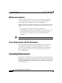
Grounding Pad Location
232131
Figure 2-1
1
1
Grounding pad
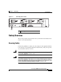
Safety Overview
This section provides safety information that you should read and understand to
ensure a safe switch installation.
Ensuring Safety
Follow these guidelines to ensure your safety and protect the equipment. This list
is not inclusive of all potentially hazardous situations that you may be exposed to
as you install the switch, so be alert.
Warning
Only trained and qualified personnel should be allowed to install, replace, or
service this equipment. Statement 1030
Warning
This equipment must be grounded. Never defeat the ground conductor or
operate the equipment in the absence of a suitably installed ground conductor.
Contact the appropriate electrical inspection authority or an electrician if you
are uncertain that suitable grounding is available. Statement 1024
Cisco Catalyst 4900M Switch Installation Guide
78-18350-01
2-5
Chapter 2
Site Planning
Safety Overview
Note
To completely de-energize the system, unplug the power cord.
•
Always use caution when lifting heavy equipment. See the “Lifting the
Chassis Safely” section on page 3-4 before lifting the Catalyst 4900M switch.
•
Always turn all power supplies off by unplugging all power cords before
installing or removing a chassis.
•
Keep the chassis area clear and free of dust during and after installation.
•
Keep tools and chassis components off of the floor and away from foot traffic.
•
Avoid wearing jewelry (including rings and chains) or other items that could
get caught in the chassis. Avoid wearing any loose clothing, or securely fasten
items such as ties, scarves, or sleeves.
•
Install the system in compliance with the following local and national
electrical codes:
– United States—National Fire Protection Association (NFPA 70); United
States National Electrical Code
– Canada—Canadian Electrical Code, Part I, CSA C22.1
– Other countries—International Electrotechnical Commission (IEC)
60364, Part 1 through Part 7
Working Safely with Electricity
Follow these basic guidelines when working with any electrical equipment:
•
Locate the emergency power-off switch for the room in which you are
working before beginning installation.
•
Disconnect all power and external cables before installing or removing a
chassis.
•
Do not work alone when potentially hazardous conditions exist.
•
Never assume that power has been disconnected from a circuit; always check.
•
Do not perform any action that creates a potential hazard to people or makes
the equipment unsafe.
Cisco Catalyst 4900M Switch Installation Guide
2-6
78-18350-01
Chapter 2
Site Planning
Site Planning Checklist
•
Examine your work area carefully for possible hazards such as moist floors,
ungrounded power extension cables, and missing safety grounds.
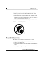
Preventing Electrostatic Discharge Damage
Electrostatic discharge (ESD) damage occurs when electronic cards or
components are improperly handled and can result in complete or intermittent
failures. Follow these guidelines to prevent ESD damage:
•
Always use an ESD-preventive wrist or ankle strap, and ensure that it makes
maximum contact with the skin.
•
When coming into contact with any internal components, always use a wrist
strap connected to one of the following:
– ESD wrist strap connector
– Any unpainted grounded surface on the chassis or equipment rack
Caution
Periodically check the resistance value of the antistatic strap. The measurement
should be between 1 and 10 megohms (Mohms).
•
Handle cards by the edges only.
•
Avoid contact between the modules and clothing. The wrist strap protects
only the card from ESD voltages on the body; ESD voltages on clothing can
still cause damage.
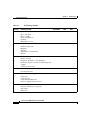
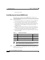
Site Planning Checklist
Table 2-1 lists the site planning activities that you should perform before you
install the Catalyst 4900M switch. Completing each activity helps to ensure a
successful switch installation.
Cisco Catalyst 4900M Switch Installation Guide
78-18350-01
2-7
Chapter 2
Site Planning
Site Planning Checklist
Table 2-1
Site Planning Checklist
Task No.
Planning Activity
1
Space evaluation:
Verified By
Time
Date
Space and layout
Floor covering
Shock and vibration
Lighting
Maintenance access
2
Environmental evaluation:
Ambient temperature
Humidity
Altitude
Atmospheric contamination
Airflow
3
Power evaluation:
Input power type
Receptacle proximity to the equipment
Dedicated (separate) circuits for redundant power
supplies
UPS for power failures
4
Grounding evaluation:
Circuit breaker size
5
Cable and interface equipment evaluation:
Cable type
Connector type
Cable distance limitations
Interface equipment (transceivers)
6
EMI evaluation:
Distance limitations for signaling
Site wiring
RFI levels
Cisco Catalyst 4900M Switch Installation Guide
2-8
78-18350-01
CH A P T E R
3
Installing the Switch
This chapter describes how to install the Catalyst 4900M switch. For first-time
installations, perform the procedures in the following sections in the order listed.
Note
•
Checking the Contents, page 3-1
•
Rack-Mounting the Switch, page 3-2
•
Connecting Power to the Catalyst 4900M Switch, page 3-11
•
Connecting DC Power to the Catalyst 4900M Switch, page 3-13
•
Optical Connections, page 3-15
•
Configurable Modules, page 3-15
Before starting the installation procedures in this chapter, complete the site
planning checklist in Chapter 2, “Site Planning,” to verify that all planning
activities were completed.
Checking the Contents
Note
Do not discard the shipping container when you unpack the switch. Flatten the
shipping cartons and store them. You will need the container if you need to move
or ship the switch in the future.
Cisco Catalyst 4900M Switch Installation Guide
78-18350-01
3-1
Chapter 3
Installing the Switch
Rack-Mounting the Switch
To check the contents of the shipping container follow these steps:
Step 1
Step 2
Check the contents of the accessories kit against the packing slip. Verify that you
received all listed equipment, which should include the following:
•
Switch hardware and software documentation, if ordered
•
Optional equipment that you ordered, such as network interface cables,
transceivers, or special connectors
To begin installation, proceed to the “Rack-Mounting the Switch” section on
page 3-2.
Rack-Mounting the Switch
A standard rack-mount kit is included for mounting the switch in a standard
19-inch (48.3 cm) four-post equipment rack. A standard equipment rack has two
unobstructed front posts, a minimum depth between the front and rear mounting
posts of 19.25 inches (48.9 cm), and a maximum depth of 32 inches (81.3 cm).
This kit is not suitable for racks with obstructions (such as a power strip) that
could impair access to the switch.
A separate mounting kit for a two-post telco rack is available, and differs mainly
in the dimensions and in the absence of the rear mounts.
Caution
Before installing the chassis in a rack, read the “Site Environmental
Requirements” section on page 2-1 to become familiar with the proper site and
environmental conditions. Failure to read and follow these guidelines could lead
to an unsuccessful installation and possible damage to the system and
components.
Caution
This unit is meant to be rack-mounted, and is not intended to bear more than its
own weight. Do not stack more than two on a table top, the added weight may
damage the bottom chassis.
Cisco Catalyst 4900M Switch Installation Guide
3-2
78-18350-01
Chapter 3
Installing the Switch
Rack-Mounting the Switch
Warning
To prevent bodily injury when mounting or servicing this unit in a rack, you
must take special precautions to ensure that the system remains stable. The
following guidelines are provided to ensure your safety:
•
This unit should be mounted at the bottom of the rack if it is the only unit in the rack.
•
When mounting this unit in a partially filled rack, load the rack from the bottom to the
top with the heaviest component at the bottom of the rack.
•
If the rack is provided with stabilizing devices, install the stabilizers before mounting
or servicing the unit in the rack. Statement 1006
Rack-Mounting Guidelines
Before rack-mounting the switch, ensure the following:
•
The equipment rack is the proper size.
– The width of the rack, between the two front mounting strips or rails,
must be 17.75 inches (45.09 cm).
– The depth of the rack, between the front and rear mounting strips, must
be at least 19.25 inches (48.9 cm) but not more than 32 inches (81.3 cm).
– The rack must have sufficient vertical clearance to insert the chassis. The
chassis height is 1.75 inches (4.45 cm).
•
The equipment rack is stable and in no danger of falling over.
– Ensure that the shelf is constructed to support the weight and dimensions
of the chassis. For physical specifications, see Appendix A,
“Specifications.”
– We recommend that you bolt the rack to the floor.
– Mount the unit at the bottom of the rack if it is the only unit in the rack.
– Install heavier equipment in the lower half of the rack to maintain a low
center of gravity and prevent the rack from becoming top-heavy and
tipping over.
– Install the stabilizers before mounting or servicing the switch in the rack
(if the rack is provided with stabilizing devices).
Cisco Catalyst 4900M Switch Installation Guide
78-18350-01
3-3
Chapter 3
Installing the Switch
Rack-Mounting the Switch
•
The equipment rack is properly ventilated.
– Install the chassis in an enclosed rack only if it has adequate ventilation
or an exhaust fan; use an open rack whenever possible.
– Ensure that the ambient temperature of the rack environment does not
exceed a maximum temperature of 104° F (40° C). Note that if the switch
is installed in a closed or multiunit rack assembly, the ambient operating
temperature of the rack environment might be higher than the ambient
room temperature.
– Note that a ventilation system in a closed rack that is too powerful might
also prevent cooling by creating negative pressure around the chassis and
redirecting the air away from the chassis intake vent. If necessary,
operate the chassis with the rack open.
–
To prevent airflow restriction, allow at least 3 inches (7.6 cm) of
clearance around the ventilation openings on the sides of the chassis.
– Use baffles correctly to assist in cooling the chassis.
– Note that equipment near the bottom of a rack may generate excessive
heat that is drawn upward and into the intake ports of equipment above,
leading to overtemperature conditions in the chassis at or near the top of
the rack.
– Consider the equipment and cabling that is already installed in the rack.
Ensure that cables from other equipment will not obstruct the airflow
through the chassis or impair access to the power supplies or switching
modules. Route cables away from field-replaceable components to avoid
disconnecting cables unnecessarily for equipment maintenance or
upgrades.
– Allow at least 3 to 4 feet (91.4 to 121.9 cm) of clearance behind the rack
for maintenance and removal of switch assemblies. If the rack is mobile,
you can push it back within 1 foot (30.45 cm) of a wall or cabinet for
normal operation and pull it out when necessary for maintenance.
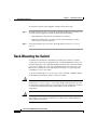
Lifting the Chassis Safely
The chassis is not intended to be moved frequently. Before you install the switch,
ensure that your site is properly prepared so that you can avoid moving the chassis
later to accommodate power sources and network connections.
Cisco Catalyst 4900M Switch Installation Guide
3-4
78-18350-01
Chapter 3
Installing the Switch
Rack-Mounting the Switch
Whenever you lift a chassis or any heavy object, follow these guidelines:
•
Ensure that your footing is solid, and balance the weight of the chassis
between your feet.
•
Lift the chassis slowly; never move suddenly or twist your body as you lift.
•
Keep your back straight and lift with your legs, not your back. If you must
bend down to lift the chassis, bend at the knees, not at the waist, to reduce the
strain on your lower back muscles. (See Figure 3-1.)
•
Always disconnect all external cables before lifting or moving the chassis.
Unsafe Lifting Practices
H1369a
Figure 3-1
Required Installation Tools
The following tools and equipment are required to install the chassis:
•
Number 1, number 2 Phillips, and 3/16-inch flat-blade screwdriver
•
Antistatic mat or antistatic foam
•
Your own ESD grounding strap or the disposable ESD strap included with the
system
The following tools and equipment are required to install the chassis in a rack:
•
Rack-mount kit
Cisco Catalyst 4900M Switch Installation Guide
78-18350-01
3-5
Chapter 3
Installing the Switch
Rack-Mounting the Switch
•
Tape measure and level
Rack-Mounting the Catalyst 4900M Switch
Follow these steps to install the Catalyst 4900M switch in a four-post rack.
Step 1
Prepare for installation:
a.
Place the chassis on the floor or on a sturdy table as close as possible to the
rack. Leave enough clearance to allow you to move around the chassis.
b.
Use a tape measure to measure the depth of the rack. Measure from the
outside of the front mounting posts to the outside of the rear mounting strip.
The depth must be at least 19.0 inches (48.2 cm) but not greater than
28 inches (71.1 cm).
c.
Measure the space between the inner edges of the left front and right front
mounting posts to ensure that it is 17.75 inches (45.09 cm) wide. (The chassis
is 17.5 inches [44 cm] wide and must fit between the mounting posts.)
d.
Open the rack-mount kit, and refer to the component checklist to verify that
all parts are included.
Table 3-1
Quantity
Part Description
2
L brackets
12
M4 Phillips Flat-head screws
4
12-24 x 3/4-inch Phillips binder-head screws
4
10-32 x 3/4-inch Phillips binder-head screws
Note
Step 2
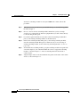
Rack-Mount Kit Checklist
Received
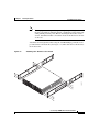
Figure 3-2 illustrates how to attach the front of the switch to the rack. You
will also need to attach the rear of the switch to the rack.
Note that the L brackets connect the chassis to the rack. You can mount the
L brackets to the front or rear mounting holes of the chassis, depending on which
end is in the front of the rack.
Cisco Catalyst 4900M Switch Installation Guide
3-6
78-18350-01
Chapter 3
Installing the Switch
Rack-Mounting the Switch
Note
Some equipment racks provide a power strip along the length of one of
the rear posts. If the rack has this feature, consider the position of the strip
when planning fastener points. Before installing the L brackets on the
chassis, determine whether to install the chassis from the front or the rear
of the rack.
Attach the left and right L brackets using the four M4 Phillips pan-head screws
provided in the rack-mount kit. (See Figure 3-2.) Then slide the rear bracket into
the front bracket.
232125
Attaching the L Brackets to the Switch
202519
Figure 3-2
Cisco Catalyst 4900M Switch Installation Guide
78-18350-01
3-7
Chapter 3
Installing the Switch
Rack-Mounting the Switch
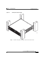
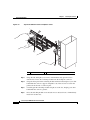
Step 3
Install the chassis in the rack as follows:
a.
Position the chassis in the rack (see Figure 3-3):
– If the chassis front panel is in the front of the rack, insert the rear of the
chassis between the mounting posts.
– If the rear of the chassis is in the front of the rack, insert the front of the
chassis between the mounting posts.
b.
Align the mounting holes in the front and rear L brackets with the mounting
holes in the equipment rack.
c.
Secure the chassis using eight (two on each flange) 12-24 x 3/4-inch screws
through the elongated holes in the L brackets and into the threaded holes in
the mounting posts.
d.
Use a tape measure and level to ensure that the chassis is installed straight and
level.
Cisco Catalyst 4900M Switch Installation Guide
3-8
78-18350-01
Chapter 3
Installing the Switch
Rack-Mounting the Switch
Installing the Switch in the Rack
232126
202519
Figure 3-3
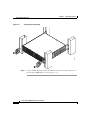
Step 4
Attach the cable guide to the right or left side of the chassis mount.
Cisco Catalyst 4900M Switch Installation Guide
78-18350-01
3-9
Chapter 3
Installing the Switch
Rack-Mounting the Switch
Installing the Cable Guide
232127
Figure 3-4
Step 5
Do not connect the power cord at this time. Proceed to the “Connecting Power to
the Catalyst 4900M Switch” section on page 3-11.
Cisco Catalyst 4900M Switch Installation Guide
3-10
78-18350-01
Chapter 3
Installing the Switch
Connecting Power to the Catalyst 4900M Switch
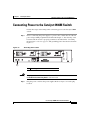
Connecting Power to the Catalyst 4900M Switch
Follow these steps and warnings when connecting power to the Catalyst 4900M
switch:
Step 1
Grounding Pad Location
232131
Figure 3-5
Prior to connecting the power supply to a power source, ensure that all of the site
power and grounding requirements described in Chapter 2, “Site Planning,” have
been met and the chassis is properly grounded as described in the “Grounding
Requirements” section on page 2-4. The grounding pad for the switch is shown in
Figure 3-5.
1
1
Warning
Step 2
Grounding pad
The plug-socket combination must be accessible at all times because it serves
as the main disconnecting device. Statement 1019
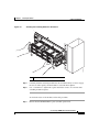
Plug the power cords into the power supplies. Refer to Figure 3-6 for the plug
location.
Cisco Catalyst 4900M Switch Installation Guide
78-18350-01
3-11
Chapter 3
Installing the Switch
Connecting Power to the Catalyst 4900M Switch
Figure 3-6
2
3
2
1
232129
1
AC Power Supply
4
5
6
1
Captive screw
4
AC power connection
2
Handle
5
INPUT OK LED
3
On/off switch
6
OUTPUT OK LED
Step 3
Connect the other end of the power cords to an AC-power input source. If both
power supplies will be used, make sure they are on different circuits.
Step 4
Turn the power switches to the ON position.
Step 5
Verify power supply operation by looking at the front panel power supply LEDs:
•
The PS1 or PS2 LED is green when the power supply and fans are functioning
normally.
•
The PS1 or PS2 LED is red when the power supply is not functioning
normally. The on/off switch may be set to off while the power supply is
plugged in, or the power supply may be defective and not providing DC
power to the switch. There may also be a fan failure.
•
The PS1 or PS2 LED is off when there is no power supply installed.
From the system console, enter the show power command to display the power
supply and system status. For more information on this command, see the
command reference publication for your software release.
Cisco Catalyst 4900M Switch Installation Guide
3-12
78-18350-01
Chapter 3
Installing the Switch
Connecting DC Power to the Catalyst 4900M Switch
If the LEDs or show power command indicate a power or other system problem,
see Chapter 4, “Troubleshooting the Installation,” for troubleshooting
information.
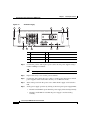
Connecting DC Power to the Catalyst 4900M Switch
Follow these steps and warnings when connecting DC power to the
Catalyst 4900M switch:
Warning
Before performing any of the following procedures, ensure that power is
removed from the DC circuit. Statement 1003
Warning
This unit is intended for installation in restricted access areas. A restricted
access area can be accessed only through the use of a special tool, lock and
key, or other means of security. Statement 1017
Warning
This product requires short-circuit (overcurrent) protection, to be provided as
part of the building installation. Install only in accordance with national and
local wiring regulations. Statement 1045
Warning
Hazardous voltage or energy may be present on DC power terminals. Always
replace cover when terminals are not in service. Be sure uninsulated
conductors are not accessible when cover is in place. Statement 1075
Step 1
Prior to connecting the power supply to a power source, ensure that all of the site
power and grounding requirements described in Chapter 2, “Site Planning,” have
been met and the chassis is properly grounded as described in the “Grounding
Requirements” section on page 2-4.
Step 2
Remove the safety cover from the power terminal.
Step 3
Connect the power supply ground terminal to earth ground.
Cisco Catalyst 4900M Switch Installation Guide
78-18350-01
3-13
Chapter 3
Installing the Switch
Connecting DC Power to the Catalyst 4900M Switch
1
DC Power Supply
2
3
4
Step 4
5
7
6
2
1
8
1
Captive screw
5
Positive terminals
2
Handle
6
Negative terminals
3
On/off switch
7
INPUT OK LED
4
Ground terminal
8
OUTPUT OK LED
232130
Figure 3-7
Connect the positive and negative power cables into the power supplies using a
number 2 Phillips screwdriver.
Note
The DC power cables may use AWG #10 to AWG #12 wire.
Step 5
Replace the safety cover over the power terminals.
Step 6
Connect the other end of the power cables to an DC-power input source. If both
power supplies will be used, make sure they are on different circuits.
Step 7
Turn on the power from the power source. Turn the DC supply on/off switch to
ON.
Step 8
Verify power supply operation by looking at the front panel power supply LEDs:
•
The PS1 or PS2 LED is green when the power supply is functioning normally.
•
The PS1 or PS2 LED is red when the power supply is not functioning
normally.
Cisco Catalyst 4900M Switch Installation Guide
3-14
78-18350-01
Chapter 3
Installing the Switch
Optical Connections
•
The PS1 or PS2 LED is off when the power supply is not connected to a power
source.
From the system console, enter the show power command to display the power
supply and system status. For more information on this command, see the
command reference publication for your software release.
If the LEDs or show power command indicate a power or other system problem,
see Chapter 4, “Troubleshooting the Installation,” for troubleshooting
information.
Optical Connections
The Cisco 4900M switch has up to 24 ports that can be configured with X2
modules with SC connectors. Module types supported are documented at:
http://www.cisco.com/en/US/products/hw/modules/ps5455/products_device_sup
port_table09186a00803857e7.html
Generic connection instructions for the X2 modules are at:
http://www.cisco.com/en/US/docs/interfaces_modules/transceiver_modules/inst
allation/note/78_16705.html
Installation documentation for Cisco TwinGig converter modules can be found at:
http://www.cisco.com/en/US/docs/switches/lan/catalyst3750e_3560e/hardware/i
nstall/notes/1757202.html
Configurable Modules
All Catalyst 4900M modules support hot swapping, which lets you install,
remove, replace, and rearrange switching modules without turning off the system
power. When the system detects that a switching module has been installed or
removed, it runs diagnostic and discovery tests automatically, acknowledges the
presence or absence of the module, and resumes system operation with no
operator intervention.
Cisco Catalyst 4900M Switch Installation Guide
78-18350-01
3-15
Chapter 3
Installing the Switch
Configurable Modules
This section describes the following topics:
•
Required Tools, page 3-16
•
Removing Switching Modules, page 3-16
•
Installing Switching Modules, page 3-19
Required Tools
You will need these tools to install supervisor engines and switching modules in
the Catalyst 4900M series switches:
Note
•
Number 1 and number 2 Phillips screwdrivers for the captive installation
screws on most modules
•
3/16-inch flat-blade screwdriver for the captive installation screws on other
modules
•
Antistatic mat or antistatic foam
•
Wrist strap or other grounding device
Whenever you handle switching modules, use a wrist strap or other grounding
device to prevent ESD damage.
Removing Switching Modules
Warning
Invisible laser radiation may be emitted from disconnected fibers or
connectors. Do not stare into beams or view directly with optical instruments.
Statement 1051
Warning
Hazardous voltage or energy is present on the backplane when the system is
operating. Use caution when servicing. Statement 1034
Cisco Catalyst 4900M Switch Installation Guide
3-16
78-18350-01
Chapter 3
Installing the Switch
Configurable Modules
Warning
Caution
Voltages that present a shock hazard may exist on Power over Ethernet (PoE)
circuits if interconnections are made using uninsulated exposed metal
contacts, conductors, or terminals. Avoid using such interconnection methods,
unless the exposed metal parts are located within a restricted access location
and users and service people who are authorized within the restricted access
location are made aware of the hazard. A restricted access area can be
accessed only through the use of a special tool, lock and key or other means of
security. Statement 1072
To prevent ESD damage, handle switching modules by the carrier edges only.
To remove a switching module from a Catalyst 4900M series switch, follow this
procedure:
Step 1
Disconnect any network interface cables attached to the ports on the switching
module that you intend to remove.
Step 2
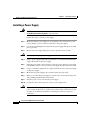
Loosen the captive installation screws. (See Figure 3-8.)
Cisco Catalyst 4900M Switch Installation Guide
78-18350-01
3-17
Chapter 3
Installing the Switch
Configurable Modules
Figure 3-8
Captive Installation Screws and Ejector Levers
2
2
1
1
Captive screw
2
232517
1
Ejector lever
Step 3
Grasp the left and right ejector levers, and simultaneously pivot the levers
downward to release the switching module from the backplane connector.
Step 4
Grasp the front panel of the switching-module with one hand, and place your other
hand under the carrier to support and guide it out of the slot. Do not touch the
printed circuit boards or connector pins.
Step 5
Carefully pull the switching module straight out of the slot, keeping your other
hand under the carrier to guide it.
Step 6
Place the switching module on an antistatic mat or antistatic foam, or immediately
install it in another slot.
Cisco Catalyst 4900M Switch Installation Guide
3-18
78-18350-01
Chapter 3
Installing the Switch
Configurable Modules
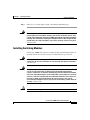
Step 7
Warning
If the slot is to remain empty, install a switching-module filler plate.
Blank faceplates and cover panels serve three important functions: they
prevent exposure to hazardous voltages and currents inside the chassis; they
contain electromagnetic interference (EMI) that might disrupt other equipment;
and they direct the flow of cooling air through the chassis. Do not operate the
system unless all cards, faceplates, front covers, and rear covers are in place.
Statement 1029
Installing Switching Modules
All Catalyst 4900M series supervisor engine modules and switching modules are
installed in horizontal chassis slots that are numbered from top to bottom.
Warning
Invisible laser radiation may be emitted from disconnected fibers or
connectors. Do not stare into beams or view directly with optical instruments.
Statement 1051
Warning
Voltages that present a shock hazard may exist on Power over Ethernet (PoE)
circuits if interconnections are made using uninsulated exposed metal
contacts, conductors, or terminals. Avoid using such interconnection methods,
unless the exposed metal parts are located within a restricted access location
and users and service people who are authorized within the restricted access
location are made aware of the hazard. A restricted access area can be
accessed only through the use of a special tool, lock and key or other means of
security. Statement 1072
Caution
To prevent ESD damage, handle switching modules by the carrier edges only.
Cisco Catalyst 4900M Switch Installation Guide
78-18350-01
3-19
Chapter 3
Installing the Switch
Configurable Modules
To install a switching module in a Catalyst 4900M series switch, follow this
procedure:
Step 1
Take the necessary precautions to prevent ESD damage as described in Appendix
B and in Chapter 2.
Step 2
Choose a slot for the new switching module. Ensure that you have enough
clearance to accommodate any interface equipment that you will connect directly
to the switching module ports.
Step 3
Loosen the captive installation screws that secure the switching-module filler
plate (or the existing switching module) to the desired slot.
Step 4
Remove the switching-module filler plate (or the existing switching module).
Save the switching-module filler plate for future use. If you are removing an
existing switching module, see the “Removing Switching Modules” section on
page 3-16.
Step 5
To install the new switching module, grasp the switching-module front panel with
one hand, and place your other hand under the carrier to support the switching
module, as shown in Figure 3-9. Do not touch the printed circuit boards or
connector pins.
Step 6
Align the edges of the circuit board with the slot guides on the sides of the switch
chassis, as shown in Figure 3-9.
Cisco Catalyst 4900M Switch Installation Guide
3-20
78-18350-01
Chapter 3
Installing the Switch
Configurable Modules
Figure 3-9
Installing the Switching Module in the Chassis
1
232516
1
1
Captive screw
Step 7
Carefully slide the switching module into the slot until both ejector levers engage
the chassis sides equally and the module is seated in the backplane.
Step 8
Use a screwdriver to tighten the captive installation screws on each end of the
switching module faceplate.
To check the status of the module, follow this procedure:
Step 1
Ensure that the STATUS LED is green (module operational).
Cisco Catalyst 4900M Switch Installation Guide
78-18350-01
3-21
Chapter 3
Installing the Switch
Removing and Replacing the Power Supply
Step 2
When the switch is online, enter the show module command. Verify that the
system acknowledges the new module and that the module’s status is listed as
good in the command output.
Step 3
If the module is not operational, reseat it. If the module is still not operational,
contact your customer service representative.
Removing and Replacing the Power Supply
This section describes how to remove and install the AC and DC-input power
supplies. This information is presented in the following sections:
Warning
•
Required Tools, page 3-23
•
Removing a Power Supply, page 3-23
•
Installing a Power Supply, page 3-24
Hazardous voltage or energy is present on the backplane when the system is
operating. Use caution when servicing. Statement 1034
Locate your power supply and notice the location of the captive installation
screws.
Note
The power supplies are hot-swappable, so in redundant mode you will not need to
power down the switch to replace most power supplies. In combined mode some
slots may lose power during power supply replacement.
Cisco Catalyst 4900M Switch Installation Guide
3-22
78-18350-01
Chapter 3
Installing the Switch
Removing and Replacing the Power Supply
Required Tools
You will need a flathead or Phillips screwdriver to perform these procedures.
Removing a Power Supply
Follow these steps to remove a power supply:
Step 1
Set the power switch to the off (O) position.
Step 2
Disconnect the power cord or cords from the power supply being removed.
Step 3
Loosen the captive screws.
Caution
Use both hands to remove a power supply.
Step 4
Grasp the power supply handles and pull the power supply out an inch to unseat
the backplane connections. Place one hand underneath to support the bottom of
the power supply.
Step 5
Pull the power supply out of the bay and set it aside.
Warning
Blank faceplates and cover panels serve three important functions: they
prevent exposure to hazardous voltages and currents inside the chassis; they
contain electromagnetic interference (EMI) that might disrupt other equipment;
and they direct the flow of cooling air through the chassis. Do not operate the
system unless all cards, faceplates, front covers, and rear covers are in place.
Statement 1029
Step 6
If the power supply bay is to remain empty, install a blank power supply filler
plate over the opening. Secure the filler plate with the two mounting screws and
tighten them with a screwdriver.
Cisco Catalyst 4900M Switch Installation Guide
78-18350-01
3-23
Chapter 3
Installing the Switch
Removing and Replacing the Power Supply
Installing a Power Supply
Warning
The plug-socket combination must be accessible at all times, because it serves
as the main disconnecting device. Statement 1019
Follow these steps to install a power supply:
Step 1
Make sure that the power supply you are installing is not connected to a power
source and that a power cord is not connected to the power supply.
Step 2
Loosen the two Phillips-head screws from the power supply filler plate (if a filler
plate is present).
Step 3
Remove the power supply filler plate (if one is present) and set it aside.
Caution
Use both hands to grasp a power supply.
Step 4
Grasp a power supply handle with one hand. Place your other hand underneath to
support the bottom of the power supply.
Step 5
Slide the power supply almost all the way into the power supply bay. Press with
both thumbs evenly to correctly seat the power supply into the connections inside.
Step 6
Using a screwdriver, tighten the two captive installation screws on the front panel
of the power supply.
Step 7
Make sure the power supply power switch is in the off position (O).
Step 8
Before you connect the power supply to a power source, ensure that all site power
and grounding requirements have been met.
Step 9
Plug the power cord or cords into the power supply.
Step 10
Connect the other end of the power cord to a power input source.
Caution
In a system with multiple power supplies, connect each power supply to a separate
power source. In the event of a power source failure, if the second source is still
available, it can maintain maximum overcurrent protection for each power
connection.
Cisco Catalyst 4900M Switch Installation Guide
3-24
78-18350-01
Chapter 3
Installing the Switch
Removing and Replacing the Fan Assembly
Step 11
Press the power switch to the on (|) position.
Step 12
Verify power supply operation by checking the power supply’s front-panel LEDs.
You should see the following:
•
The LED labeled INPUT OK is green.
•
The LED labeled OUTPUT OK is green.
Step 13
Check the power supply and system status from the system console by entering
show power command. For more information on this command, refer to the
command reference publication for your switch.
Step 14
If the LEDs or show power command output indicate a power problem or other
system problem, see Chapter 4, “Troubleshooting the Installation,” for more
information.
Removing and Replacing the Fan Assembly
This section describes how to remove and install the fan assembly.
Required Tools
You will need a Phillips screwdriver for the following two procedures.
Removing the Fan Assembly
Warning
When removing the fan tray, keep your hands and fingers away from the
spinning fan blades. Let the fan blades completely stop before you remove the
fan tray. Statement 258
Cisco Catalyst 4900M Switch Installation Guide
78-18350-01
3-25
Chapter 3
Installing the Switch
Removing and Replacing the Fan Assembly
Caution
Never operate the system for an extended period if the fan assembly is removed
or if it is not functioning properly. An over-temperature condition can cause
severe equipment damage.
Follow these steps to remove the existing fan assembly:
Step 1
Loosen the two captive installation screws on the fan assembly by turning them
counterclockwise.
Step 2
Grasp the fan assembly with both hands and pull it outward; gently move it side
to side if necessary to unseat it from the backplane. Slide it out of the chassis and
place it in a safe place.
Installing the Fan Assembly
Follow these steps to install the new fan assembly:
Step 1
Hold the fan assembly with the captive screws on the left.
Step 2
Place the fan assembly into the fan assembly bay so it rests on the chassis, and
then lift the fan assembly up slightly, aligning the top and bottom guides.
Step 3
Slide the fan assembly into the chassis until the two captive installation screws
make contact with the chassis.
Step 4
Using a screwdriver, tighten the two captive installation screws by turning them
clockwise.
Cisco Catalyst 4900M Switch Installation Guide
3-26
78-18350-01
Chapter 3
Installing the Switch
Removing and Replacing the Fan Assembly
Verifying the Installation
Note
To check the operation of the fans, you need to power up the chassis.
Follow these steps to verify that the new fan assembly was installed correctly:
Step 1
Listen for the fans; you should immediately hear them operating. If you do not
hear them, ensure that the fan assembly is inserted completely in the chassis and
that the faceplate is flush with the switch back panel.
Step 2
The fan tray LED should light and be green.
Step 3
If after several attempts the fans do not operate, or if you experience trouble with
the installation (for instance, if the captive installation screws do not align with
the chassis holes), contact the Cisco TAC for assistance.
Cisco Catalyst 4900M Switch Installation Guide
78-18350-01
3-27
Chapter 3
Installing the Switch
Removing and Replacing the Fan Assembly
Cisco Catalyst 4900M Switch Installation Guide
3-28
78-18350-01
CH A P T E R
4
Troubleshooting the Installation
This chapter describes how to troubleshoot the Catalyst 4900M switch hardware
installation and contains these sections:
•
Getting Started, page 4-1
•
Problem Solving to the System Component Level, page 4-2
•
Identifying Startup Problems, page 4-2
•
Troubleshooting the Power Supply, page 4-5
•
Contacting Customer Service, page 4-6
If your system has problems starting up, use the information in this chapter to help
isolate the cause. Problems with the initial startup are often caused by poor or
improper connections. Although temperature conditions above the maximum
acceptable level rarely occur at initial startup, environmental monitoring
functions are included because they also monitor DC-line voltages.
Note
For configuration questions or problems, refer to the software configuration guide
or the command reference publication to configure or enable the interfaces.
Getting Started
When the initial system boot is complete, verify the following:
•
Power supplies are supplying power to the system.
•
The system fan assembly is operating.
Cisco Catalyst 4900M Switch Installation Guide
78-18350-01
4-1
Chapter 4
Troubleshooting the Installation
Problem Solving to the System Component Level
•
System software boots successfully.
If all of these conditions are met and the hardware installation is complete, refer
to the software configuration guide and the command reference publications to
troubleshoot the software. However, if any of these conditions are not met, use the
procedures in this chapter to isolate and, if possible, resolve the problem.
Problem Solving to the System Component Level
The key to success when troubleshooting the system is to isolate the problem to a
specific system component. The first step is to compare what the system is doing
to what it should be doing. Because a startup problem can usually be attributed to
a single component, it is more efficient to isolate the problem to a subsystem
rather than troubleshoot each separate component in the system.
The switch consists of the following subsystems:
•
Power supply—Includes the power supply and power supply cooling. (See
the “Troubleshooting the Power Supply” section on page 4-5.)
•
Fan assembly system—The chassis fan assembly should operate whenever
system power is on. Usually, it continues to operate even when the
environmental monitor shuts down the system because of an overtemperature
or overvoltage condition. (It will shut down for a power supply shutdown.)
You should be able to hear the fan assembly to determine whether or not it is
operating. If the FAN LED is orange and you determine that the fan assembly
is not operating, you should immediately contact a customer service
representative. There are no installation adjustments that you can make if the
fan assembly does not function properly at the initial startup.
Identifying Startup Problems
When you connect the power cords to the Catalyst 4900M switch, follow these
steps:
Step 1
Flip the power switches to the on position (AC powered systems only).
Step 2
Verify that power is available to the power supplied from the site AC or DC
source. Flip breakers and fuses if necessary.
Cisco Catalyst 4900M Switch Installation Guide
4-2
78-18350-01
Chapter 4
Troubleshooting the Installation
Identifying Startup Problems
Step 3
Listen for the system fan assembly. If you do not immediately hear the system fan
assembly begin to operate, see “Troubleshooting the Power Supply” section on
page 4-5.
Step 4
If you determine that the power supplies are functioning normally and that the fan
assembly is faulty, contact a customer service representative. If the system fan
assembly does not function properly at initial startup, there are no installation
adjustments that you can make.
LED Readings
LEDs indicate all system states in the startup sequence. By checking the LEDs,
you can determine when and where the system failed in the startup sequence. To
check the LEDs, follow these steps:
Step 1
Compare the LED states to Table 4-1:
Cisco Catalyst 4900M Switch Installation Guide
78-18350-01
4-3
Chapter 4
Troubleshooting the Installation
Identifying Startup Problems
Table 4-1
Power Supply LED Meanings
LED and Color
Meaning
INPUT OK (AC)
This LED should turn green immediately when power is
applied to the supply and the power switch is set to ON.
Green
AC input voltage is greater than 80.5 +/- 4.5 V AC.
Red
In a dual power supply configuration (alternate unit
powered) the AC input is less than 73 +/-3V, or the power
supply is turned off.
In a single supply configuration, signals that AC input
voltage is less than 73 +/-3V, or the power supply is turned
off.
Off
INPUT OK (DC)
This LED should turn green immediately when power is
applied to the supply.
Green
DC input voltage is greater than -38.25 +/-2.25V.
Red
In a dual power supply configuration (alternate unit
powered) the DC input is less than 33 +/-3V, or the power
supply is turned off.
Off
In a single supply configuration, the LED shall be off to
signal that DC input is less than 33 +/-3V, or the power
supply is turned off.
OUTPUT OK
Step 2
Green
DC output voltages are within the normal operating range.
Red
Output voltages below the minimum or above the
maximum will create an output fail alarm and cause the
LED to illuminate red.
Verify that the LEDs on the front panel are lit:
•
The STATUS LED flashes yellow during diagnostic boot tests. It is green
when the switch is operational (online). If the system software is unable to
start up, this LED stays orange.
Cisco Catalyst 4900M Switch Installation Guide
4-4
78-18350-01
Chapter 4
Troubleshooting the Installation
Troubleshooting the Power Supply
•
The port LEDs (1-48) are green when the module is operational (online). If
no signal is detected, the LINK LED is off. The port LED remains yellow if
the port is disabled. The port LED flashes yellow if the port tested faulty at
startup.
Step 3
If a STATUS LED is red, contact a customer service representative for
instructions.
Step 4
If the boot information and system banner are not displayed, verify that the
terminal is set correctly and that it is connected properly to the console port.
Troubleshooting the Power Supply
Follow these steps to help isolate a power subsystem problem:
Step 1
Verify that the power supply is plugged in and that the on/off switch is set to ON
(if the power supply is an AC supply).
Step 2
Look at the power supply LED (PS1 or PS2). If the LED is off or if the LED is
red, unplug the power cord, and then plug the power cord in. Be sure the on/off
switch is OFF before removing the power cord from the power supply.
Step 3
If the LED remains off, there might be a problem with the AC or DC source or the
power cable.
Step 4
Connect the power cord to another power source if one is available.
Step 5
If the LED then lights, the problem is the first power source.
Step 6
If the LED fails to light after you connect the power supply to a new power source,
replace the power cord.
Step 7
If the LED still fails to light when the switch is connected to a different power
source with a new power cord, the power supply is probably faulty.
If you are unable to resolve the problem, contact a customer service representative
for instructions.
Cisco Catalyst 4900M Switch Installation Guide
78-18350-01
4-5
Chapter 4
Troubleshooting the Installation
Contacting Customer Service
Contacting Customer Service
If you are unable to solve a startup problem after using the troubleshooting
suggestions in this chapter, contact a customer service representative for
assistance and further instructions. Before you call, have the following
information ready to help your service provider assist you as quickly as possible:
•
Date you received the switch
•
Chassis serial number (located on a label on the right of the rear of the
chassis, see Figure 4-1)
•
Type of software and release number
•
Maintenance agreement or warranty information
•
Brief description of the problem
•
Brief explanation of the steps you have already taken to isolate and resolve
the problem
Cisco Catalyst 4900M Switch Installation Guide
4-6
78-18350-01
Chapter 4
Troubleshooting the Installation
Contacting Customer Service
Serial Number Location
202519
Figure 4-1
SN: XXXNNNNXXXX
Cisco Catalyst 4900M Switch Installation Guide
78-18350-01
4-7
Chapter 4
Troubleshooting the Installation
Contacting Customer Service
Cisco Catalyst 4900M Switch Installation Guide
4-8
78-18350-01
APPENDIX
A
Specifications
This appendix provides cable and technical specifications for the Catalyst 4900M
switches.
Console Port
The console port is an RJ-45 receptacle. The Request to Send (RTS) signal tracks
the state of the Clear to Send (CTS) input. Table A-1 lists the console port pinouts.
Table A-1
Console Port Pinouts
Pin
Signal
Direction
Description
1
RTS
output
request to send
2
DTR
output
data terminal ready
3
TXD
output
transmit data
4
GND
—
—
5
GND
—
—
6
RXD
input
receive data
7
DSR
input
data set ready
8
CTS
input
clear to send
Cisco Catalyst 4900M Switch Installation Guide
78-18350-01
A-1
Appendix A
Specifications
10/100/1000BASE-T Management Port
10/100/1000BASE-T Management Port
The 10/100/1000BASE-T management port is an RJ-45 receptacle with a Link
Status LED. Table A-2 lists the 10/100BASE-T port pinouts.
Table A-2
10/100BASE-T Port Pinouts
Pin
Signal
Direction
Description
1
RXDP
input
receive data
2
RXDN
input
receive data
3
TXDP
output
transmit data
4
unused
—
—
5
unused
—
—
6
TXDN
output
transmit data
7
unused
—
—
8
unused
—
—
Catalyst 4900M Switch Specifications
Catalyst 4900M switch specifications are provided in Table A-3.
Table A-3
Catalyst 4900 Series Switch Specifications
Item
Specification
Environmental
Temperature
ambient operating
32°F (0°C) to 104°F (40°C)
Temperature
ambient nonoperating and storage
–40 to 167°F (–40 to 75°C)
Humidity (RH), ambient (noncondensing) 10% to 90%
operating
Humidity (RH), ambient (noncondensing) 5% to 95%
nonoperating and storage
Cisco Catalyst 4900M Switch Installation Guide
A-2
78-18350-01
Appendix A
Specifications
Catalyst 4900M Switch Specifications
Table A-3
Catalyst 4900 Series Switch Specifications (continued)
Item
Specification
Altitude
operating and nonoperating
–60 to 2000 m
Switch heat dissipation
723 BTU/hour
Switching Components
Memory
512-MB SDRAM, 128-MB Flash (onboard and fixed),
256 bytes serial EEROM
Physical Characteristics
Dimensions (H x W x D)
3.5 x 17.2 x 17.9 in. (8.9 x 43.7 x 45.5 cm)
Weight
34.0 lb (15.4 kg) for a system with two power supplies,
4.5 lb (2.1 kg) per power supply
Airflow
Left to right
AC Power
Power supply output
960 W
System power dissipation
240 W
AC-input
12 A maximum @ 100 VAC
5 A maximum @ 240 VAC
AC frequency
50 to 60 Hz
Output current
80 A maximum
Inrush value
50 A for one cycle of AC
Output voltage
12 V
Input KVA rating
1.200 KVA
DC Power
Power supply output
960 W
System power dissipation
320 W
DC-input
27 A @ –48 VDC (Operating range –40.5 to –56 VDC)
21.6 A @ –60 VDC (Operating range –55 to –72 VDC)
Output current
80 A maximum
Inrush value
Hot turn on (PSU on for > 1 hour) 75 A
Cisco Catalyst 4900M Switch Installation Guide
78-18350-01
A-3
Appendix A
Specifications
Catalyst 4900M Switch Specifications
Table A-3
Catalyst 4900 Series Switch Specifications (continued)
Item
Specification
Output voltage
12 V
Input KVA rating
1.296 KVA
Cisco Catalyst 4900M Switch Installation Guide
A-4
78-18350-01
APPENDIX
B
Compliance Information and
Translated Safety Warnings
Note
Only trained and qualified service personnel (as defined in IEC 60950-1 and
AS/NZS 60950) should install, replace, or service the equipment. Install the
system in accordance with the U.S. National Electric Code if you are in the United
States.
This appendix contains the following sections:
•
Regulatory Standards Compliance, page B-1
•
European Directives, page B-4
•
EMC Class A Notices and Warnings, page B-6
•
Translated Safety Warnings, page B-11
Regulatory Standards Compliance
This section includes all standards. Catalyst 4900M switches are in compliance
with national and international standards as described in Table B-1 “Class A
Regulatory Standards Compliance”, Table B-2 “Industry EMC, Safety, and
Environmental Standards”, and Table B-3 “GR-1089 Installation and Caution
Instructions”.
Cisco Catalyst 4900M Switch Installation Guide
78-18350-01
B-1
Appendix B
Compliance Information and Translated Safety Warnings
Regulatory Standards Compliance
Table B-1
Class A Regulatory Standards Compliance
Specification
Standard
Regulatory Compliance
Products with the CE Marking indicate
compliance with the 1999/5/EC directive,
which includes the safety and EMC standards
listed.
Safety
UL 60950-1
CAN/CSA-C22.2 No. 60950-1
EN 60950-1
IEC 60950-1
AS/NZS 60950-1
EMC
FCC Part 15 (CFR 47) Class A
ICES-003 Class A
EN50082-1
CISPR22 Class A
AS/NZS CISPR22 Class A
VCCI Class A
EN55022 Class A
EN55024
EN61000-3-2
EN6100-3-3
EN61000-6-1
EN300 386
KN22 Class A
KN immunity series
CISPR24
Cisco Catalyst 4900M Switch Installation Guide
B-2
78-18350-01
Appendix B
Compliance Information and Translated Safety Warnings
Regulatory Standards Compliance
Table B-2
Industry EMC, Safety, and Environmental Standards
Specification
Standard
NEBS Criteria Levels
SR-3580 Issue 3, June 2007
Verizon NEBS
Compliance
Telecommunications Carrier Group (TCG) Checklist
Qwest NEBS
Compliance
TCG Checklist
ATT NEBS requirements ATT TP76200 level 3 and TCG Checklist
ETSI
Table B-3
ETS 300 019-2-1, Class 1.1 Storage
ETS 300 019-2-2, Class 2.1 and 2.2 Transportation
ETS 300 019-2-3, Class 3.1E Stationary Use
GR-1089 Installation and Caution Instructions
Shielded cable grounded at both ends specified for copper telecom ports.
Caution
The intra-building port(s) of the equipment or subassembly is suitable
for connection to intra-building or unexposed wiring or cabling only.
The intra-building port(s) of the equipment or subassembly must not
be metallically connected to interfaces which connect to the OSP or
its wiring. These interfaces are designed for use as intra-building
interfaces only (Type 2 or Type 4 ports as described in
GR-1089-CORE, Issue 4) and require isolation from the exposed OSP
cabling. The addition of primary protectors is not sufficient
protection in order to connect these interfaces metallically to OSP
wiring.
The Catalyst 4900M Series Switches have AC power ports that are intended for
deployments where an external Surge Protective Device (SPD) is utilized at the
AC power service equipment (see definition in National Electric Code).
The Catalyst 4900M Series Switches are designed for a Common Bonding
Network (CBN) installation.
Cisco Catalyst 4900M Switch Installation Guide
78-18350-01
B-3
Appendix B
Compliance Information and Translated Safety Warnings
European Directives
Table B-3
GR-1089 Installation and Caution Instructions (continued)
The Catalyst 4900 Series Switches can be installed in network
telecommunication facilities or locations where the National Electric Code
applies.
An electrical conducting path shall exist between the product chassis and the
metal surface of the enclosure or rack in which it is mounted or to a grounding
conductor. Electrical continuity shall be provided by using thread-forming type
mounting screws that remove any paint or nonconductive coatings and establish
a metal-to-metal contact. Any paint or other nonconductive coatings shall be
removed on the surfaces between the mounting hardware and the enclosure or
rack. The surfaces shall be cleaned and an antioxidant applied before
installation.
The DC return connection to this system should remain Isolated from the system
frame and chassis (DC-I).
The nominal DC operating voltage is –48 VDC.
European Directives
Statement 275—Declaration of Conformity with Regard to the
Directives 73/23/EEC and 89/336/EEC as amended by Directive
93/68/EEC
For specifics about which standards have been applied, refer to the Declaration of
Conformity.
English:
Dansk:
This equipment is in compliance with the essential requirements and other
provisions of Directives 73/23/EEC and 89/336/EEC as amended by Directive
93/68/EEC.
Dette udstyr er i overensstemmelse med de ufravigelige hensyn og andre
bestemmelser i direktiv 73/23/EEC og 89/336/EEC som ændred i direktiv
93/68/EEC.
Cisco Catalyst 4900M Switch Installation Guide
B-4
78-18350-01
Appendix B
Compliance Information and Translated Safety Warnings
European Directives
Deutsch:
Dieses Gerät entspricht den wesentlichen Anforderungen und weiteren
Bestimmungen der Richtlinien 73/23/EWG und 89/336/EWG mit der Ergänzung
durch Richtlinie 93/68/EWG.
Español:
Este equipo cumple con los requisitos esenciales y otras disposiciones de las
Directrices 73/23/EEC y 89/336/EEC de acuerdo a las modificaciones de la
Directriz 93/68/EEC.
Français:
Cet appareil remplit les principales conditions requises et autres dispositions
des Directives 73/23/EEC et 89/336/EEC, modifiées par la Directive 93/68/EEC.
Íslenska:
Þessir búnaður samrýmist lögboðnum kröfum og öðrum ákvæðum tilskipana
73/23/EBE og 89/336/EBE, með breytingum skv. tilskipun 93/68/EBE.
Italiano:
Questa apparecchiatura è conforme ai requisiti essenziali e altre disposizioni
delle Direttive 73/23/EEC e 89/336/EEC modificate con la Direttiva 93/68/EEC.
Nederlands:
Deze apparatuur voldoet aan de belangrijkste eisen en andere voorzieningen
van richtlijnen 73/23/EEC en 89/336/EEC zoals gewijzigd door richtlijn
93/68/EEC.
Norsk:
Português:
Dette utstyret samsvarer med de vesentligste kravene og andre regler i
direktivene 73/23/EEC og 89/336/EEC samt i tilleggsdirektiv 93/68/EEC.
Este equipamento satisfaz os requisitos essenciais e outras provisões das
Directivas 73/23/EEC e 89/336/EEC, conforme amendados pela Directiva
93/68/EEC.
Catalyst 4948 and Catalyst 4900M switches
Cisco Catalyst 4900M Switch Installation Guide
78-18350-01
B-5
Appendix B
Compliance Information and Translated Safety Warnings
EMC Class A Notices and Warnings
Suomalainen:
Svenska:
Tämä laite on direktiivien 73/23/ETY ja 89/336/ETY (kuten muutettu
direktiivissä 93/68/ETY) keskeisten vaatimusten ja määräysten mukainen.
Denna utrustning uppfyller de väsentliga kraven och andra villkor i direktiven
73/23/EEC och 89/336/EEC enligt ändringarna i direktiv 93/68/EEC.
EMC Class A Notices and Warnings
This section includes the EMC Class A warnings for the Catalyst 4900M
switches.
Class A Notice for FCC
Modifying the equipment without Cisco’s authorization may result in the
equipment no longer complying with FCC requirements for Class A digital
devices. In that event, your right to use the equipment may be limited by FCC
regulations, and you may be required to correct any interference to radio or
television communications at your own expense.
This equipment has been tested and found to comply with the limits for a Class A
digital device, pursuant to Part 15 of the FCC Rules. These limits are designed to
provide reasonable protection against harmful interference when the equipment is
operated in a commercial environment. This equipment generates, uses, and can
radiate radio frequency energy and, if not installed and used in accordance with
the instruction manual, may cause harmful interference to radio communications.
Operation of this equipment in a residential area is likely to cause harmful
interference in which case users will be required to correct the interference at their
own expense.
Class A Notice for Canada
This Class A digital apparatus complies with Canadian ICES-003.
Cet appareil numérique de la classe A est conforme à la norme NMB-003 du
Canada.
Cisco Catalyst 4900M Switch Installation Guide
B-6
78-18350-01
Appendix B
Compliance Information and Translated Safety Warnings
EMC Class A Notices and Warnings
Statement 340—Class A Warning for CISPR22
Warning
Waarschuwing
Varoitus
This is a class A product. In a domestic environment this product may cause
radio interference in which case the user may be required to take adequate
measures. Statement 340
Dit is een product van klasse A. In een woonomgeving kan dit product
radiostoring veroorzaken. In dat geval moet de gebruiker de juiste
maatregelen nemen.
Tämä on A-luokan tuote. Kotona käytettynä tämä tuote voi aiheuttaa
radiotaajuushäiriöitä, jolloin käyttäjän tulisi ryhtyä vaadittaviin
toimenpiteisiin häiriöiden ehkäisemiseksi.
Attention
Il s'agit d'un produit de classe A. Dans un environnement local, ce produit peut
entraîner des perturbations radioélectriques, auquel cas l'utilisateur devra
éventuellement prendre des mesures adéquates.
Warnung
Dies ist ein Produkt der Klasse A. Bei der Verwendung dieses Produkts im
Haus- oder Wohnungsbereich kann es zu Funkstörungen kommen. In diesem
Fall muss der Benutzer u. U. angemessene Maßnahmen ergreifen.
Avvertenza
Prodotto di classe A. È possibile che il prodotto generi interferenze radio in un
ambienti chiusi. In questo caso l'utente deve intraprendere le misure
adeguate per risolvere il problema.
Advarsel
Dette er et produkt i klasse A. I et hjemmemiljø kan dette produktet forårsake
radioforstyrrelser, og brukeren kan da være nødt til å ta de nødvendige
forholdsregler.
Aviso
Este é um produto de classe A. Em um ambiente doméstico, este produto pode
causar interferência de rádio. Nesse caso, talvez o usuário precise tomar as
medidas adequadas.
Cisco Catalyst 4900M Switch Installation Guide
78-18350-01
B-7
Appendix B
Compliance Information and Translated Safety Warnings
EMC Class A Notices and Warnings
¡Advertencia!
Varning!
Este es un producto de clase A. En el ámbito doméstico, este producto puede
causar radiointerferencias, lo que puede hacer necesaria la puesta en marcha
de medidas adecuadas.
Detta är en klass A-produkt. Denna produkt kan orsaka radiostörningar
inomhus. Det kan då vara ett krav att användaren vidtar lämpliga åtgärder.
Cisco Catalyst 4900M Switch Installation Guide
B-8
78-18350-01
Appendix B
Compliance Information and Translated Safety Warnings
EMC Class A Notices and Warnings
Statement 191—VCCI Class A Warning for Japan
Warning
This is a Class A product based on the standard of the Voluntary Control
Council for Interference by Information Technology Equipment (VCCI). If this
equipment is used in a domestic environment, radio disturbance may arise.
When such trouble occurs, the user may be required to take corrective
actions.
Cisco Catalyst 4900M Switch Installation Guide
78-18350-01
B-9
Appendix B
Compliance Information and Translated Safety Warnings
EMC Class A Notices and Warnings
Statement 256—Class A Warning for Hungary
Warning
This equipment is a class A product and should be used and installed properly
according to the Hungarian EMC Class A requirements (MSZEN55022). Class A
equipment is designed for typical commercial establishments for which
special conditions of installation and protection distance are used.
Statement 294—Class A Warning for Korea
Warning
This is a Class A Device and is registered for EMC requirements for industrial
use. The seller or buyer should be aware of this. If this type was sold or
purchased by mistake, it should be replaced with a residential-use type.
Cisco Catalyst 4900M Switch Installation Guide
B-10
78-18350-01
Appendix B
Compliance Information and Translated Safety Warnings
Translated Safety Warnings
Statement 257—Class A Notice for Taiwan and Other Traditional
Chinese Markets
Warning
This is a Class A Information Product, when used in residential environment,
it may cause radio frequency interference, under such circumstances, the
user may be requested to take appropriate countermeasures. Statement 257
Statement 371—Power Cable and AC Adapter
Translated Safety Warnings
This section repeats in multiple languages the warnings in this guide.
Cisco Catalyst 4900M Switch Installation Guide
78-18350-01
B-11
Appendix B
Compliance Information and Translated Safety Warnings
Translated Safety Warnings
Statement 258—Fan Tray Removal Warning
Warning
Waarschuwing
When removing the fan tray, keep your hands and fingers away from the
spinning fan blades. Let the fan blades completely stop before you remove the
fan tray. Statement 258
Houd tijdens het verwijderen van de ventilator de handen en vingers uit de
buurt van de draaiende ventilatorschoepen. Laat de ventilatorschoepen
volledig tot stilstand komen alvorens de ventilator te verwijderen.
Varoitus
Pidä kädet ja sormet pois tuulettimen pyörivistä siivistä tuuletinalustaa
poistaessasi. Anna tuulettimen siipien pysähtyä kokonaan ennen kuin irrotat
tuuletinalustan.
Attention
Lors du retrait du plateau du ventilateur, veillez à ce que vos mains et doigts
restent à l’écart des pales en rotation du ventilateur. Attendez que les pales
du ventilateur soient parvenues à une immobilité complète avant de retirer le
plateau du ventilateur.
Warnung
Beim Herausnehmen des Lüfterkastens Hände und Finger von den sich
drehenden Gebläseflügeln fern halten. Vor Herausnehmen des
Gebläsekastens warten, bis die Gebläseflügel völlig zum Stillstand
gekommen sind.
Avvertenza
Advarsel
Aviso
Quando si toglie il vano della ventola, fare attenzione che le mani e le dita non
vengano in contatto con la ventola in movimento. Attendere che la ventola si
fermi completamente prima di togliere il vano.
Når du fjerner viftedekselet, hold hender og fingre borte fra de roterende
viftebladene. La viftebladene stanse helt før du fjerner viftedekselet.
Mantenha as suas mãos e dedos afastados das lâminas em movimento da
ventoinha, ao retirar a respectiva bandeja. Deixe as lâminas da ventoinha
parar completamente antes de retirar a bandeja.
Cisco Catalyst 4900M Switch Installation Guide
B-12
78-18350-01
Appendix B
Compliance Information and Translated Safety Warnings
Translated Safety Warnings
¡Advertencia!
Varning!
Cuando quite la bandeja del abanico, mantenga las manos y los dedos
alejados de las aspas en movimiento. Deje que las aspas se detengan
completamente antes de quitar la bandeja del abanico.
Håll händer och fingrar borta från de roterande fläktbladen när du tar av
fläktskyddet. Låt fläkten stanna helt innan du tar av fläktskyddet.
Cisco Catalyst 4900M Switch Installation Guide
78-18350-01
B-13
Appendix B
Compliance Information and Translated Safety Warnings
Translated Safety Warnings
Statement 1003—DC Power Disconnection
Warning
Before performing any of the following procedures, ensure that power is
removed from the DC circuit. Statement 1003
Waarschuwing
Voordat u een van de onderstaande procedures uitvoert, dient u te controleren
of de stroom naar het gelijkstroom circuit uitgeschakeld is.
Varoitus
Varmista, että tasavirtapiirissä ei ole virtaa ennen seuraavien toimenpiteiden
suorittamista.
Attention
Avant de pratiquer l'une quelconque des procédures ci-dessous, vérifier que
le circuit en courant continu n'est plus sous tension.
Warnung
Vor Ausführung der folgenden Vorgänge ist sicherzustellen, daß die
Gleichstromschaltung keinen Strom erhält.
Avvertenza
Prima di svolgere una qualsiasi delle procedure seguenti, verificare che il
circuito CC non sia alimentato.
Advarsel
Før noen av disse prosedyrene utføres, kontroller at strømmen er frakoblet
likestrømkretsen.
Aviso
Antes de executar um dos seguintes procedimentos, certifique-se que
desligou a fonte de alimentação de energia do circuito de corrente contínua.
¡Advertencia!
Antes de proceder con los siguientes pasos, comprobar que la alimentación
del circuito de corriente continua (CC) esté cortada (OFF).
Varning!
Aviso
Innan du utför någon av följande procedurer måste du kontrollera att
strömförsörjningen till likströmskretsen är bruten.
Antes de executar qualquer um dos procedimentos a seguir, verifique se a
energia foi removida do circuito DC.
Cisco Catalyst 4900M Switch Installation Guide
B-14
78-18350-01
Appendix B
Compliance Information and Translated Safety Warnings
Translated Safety Warnings
Advarsel
Før du udfører nogen af følgende procedurer, skal du sikre dig, at der ikke er
strøm til jævnstrømskredsløbet.
Statement 1004—Installation Instructions
Warning
Read the installation instructions before connecting the system to the power
source. Statement 1004
Waarschuwing
Raadpleeg de installatie-instructies voordat u het systeem op de voedingsbron
aansluit.
Varoitus
Lue asennusohjeet ennen järjestelmän yhdistämistä virtalähteeseen.
Cisco Catalyst 4900M Switch Installation Guide
78-18350-01
B-15
Appendix B
Compliance Information and Translated Safety Warnings
Translated Safety Warnings
Attention
Avant de brancher le système sur la source d'alimentation, consulter les
directives d'installation.
Warnung
Vor dem Anschließen des Systems an die Stromquelle die
Installationsanweisungen lesen.
Avvertenza
Advarsel
Consultare le istruzioni di installazione prima di collegare il sistema
all'alimentatore.
Les installasjonsinstruksjonene før systemet kobles til strømkilden.
Aviso
Leia as instruções de instalação antes de ligar o sistema à fonte de energia.
¡Advertencia!
Lea las instrucciones de instalación antes de conectar el sistema a la red de
alimentación.
Varning!
Läs installationsanvisningarna innan du kopplar systemet till
strömförsörjningsenheten.
Cisco Catalyst 4900M Switch Installation Guide
B-16
78-18350-01
Appendix B
Compliance Information and Translated Safety Warnings
Translated Safety Warnings
Cisco Catalyst 4900M Switch Installation Guide
78-18350-01
B-17
Appendix B
Compliance Information and Translated Safety Warnings
Translated Safety Warnings
Statement 1006—Chassis Warning for Rack-Mounting and
Servicing
Warning
Waarschuwing
Varoitus
To prevent bodily injury when mounting or servicing this unit in a rack, you
must take special precautions to ensure that the system remains stable. The
following guidelines are provided to ensure your safety:
•
This unit should be mounted at the bottom of the rack if it is the only unit in the rack.
•
When mounting this unit in a partially filled rack, load the rack from the bottom to the
top with the heaviest component at the bottom of the rack.
•
If the rack is provided with stabilizing devices, install the stabilizers before mounting
or servicing the unit in the rack. Statement 1006
Om lichamelijk letsel te voorkomen wanneer u dit toestel in een rek monteert
of het daar een servicebeurt geeft, moet u speciale voorzorgsmaatregelen
nemen om ervoor te zorgen dat het toestel stabiel blijft. De onderstaande
richtlijnen worden verstrekt om uw veiligheid te verzekeren:
•
Dit toestel dient onderaan in het rek gemonteerd te worden als het toestel het enige
in het rek is.
•
Wanneer u dit toestel in een gedeeltelijk gevuld rek monteert, dient u het rek van
onderen naar boven te laden met het zwaarste onderdeel onderaan in het rek.
•
Als het rek voorzien is van stabiliseringshulpmiddelen, dient u de stabilisatoren te
monteren voordat u het toestel in het rek monteert of het daar een servicebeurt geeft.
Kun laite asetetaan telineeseen tai huolletaan sen ollessa telineessä, on
noudatettava erityisiä varotoimia järjestelmän vakavuuden säilyttämiseksi,
jotta vältytään loukkaantumiselta. Noudata seuraavia turvallisuusohjeita:
•
Jos telineessä ei ole muita laitteita, aseta laite telineen alaosaan.
•
Jos laite asetetaan osaksi täytettyyn telineeseen, aloita kuormittaminen sen
alaosasta kaikkein raskaimmalla esineellä ja siirry sitten sen yläosaan.
•
Jos telinettä varten on vakaimet, asenna ne ennen laitteen asettamista telineeseen
tai sen huoltamista siinä.
Cisco Catalyst 4900M Switch Installation Guide
B-18
78-18350-01
Appendix B
Compliance Information and Translated Safety Warnings
Translated Safety Warnings
Attention
Warnung
Avvertenza
Pour éviter toute blessure corporelle pendant les opérations de montage ou de
réparation de cette unité en casier, il convient de prendre des précautions
spéciales afin de maintenir la stabilité du système. Les directives ci-dessous
sont destinées à assurer la protection du personnelþ:
•
Si cette unité constitue la seule unité montée en casier, elle doit être placée dans le
bas.
•
Si cette unité est montée dans un casier partiellement rempli, charger le casier de
bas en haut en plaçant l'élément le plus lourd dans le bas.
•
Si le casier est équipé de dispositifs stabilisateurs, installer les stabilisateurs avant
de monter ou de réparer l'unité en casier.
Zur Vermeidung von Körperverletzung beim Anbringen oder Warten dieser
Einheit in einem Gestell müssen Sie besondere Vorkehrungen treffen, um
sicherzustellen, daß das System stabil bleibt. Die folgenden Richtlinien sollen
zur Gewährleistung Ihrer Sicherheit dienen:
•
Wenn diese Einheit die einzige im Gestell ist, sollte sie unten im Gestell angebracht
werden.
•
Bei Anbringung dieser Einheit in einem zum Teil gefüllten Gestell ist das Gestell von
unten nach oben zu laden, wobei das schwerste Bauteil unten im Gestell anzubringen
ist.
•
Wird das Gestell mit Stabilisierungszubehör geliefert, sind zuerst die Stabilisatoren
zu installieren, bevor Sie die Einheit im Gestell anbringen oder sie warten.
Per evitare infortuni fisici durante il montaggio o la manutenzione di questa
unità in un supporto, occorre osservare speciali precauzioni per garantire che
il sistema rimanga stabile. Le seguenti direttive vengono fornite per garantire
la sicurezza personale:
•
Questa unità deve venire montata sul fondo del supporto, se si tratta dell’unica unità
da montare nel supporto.
•
Quando questa unità viene montata in un supporto parzialmente pieno, caricare il
supporto dal basso all’alto, con il componente più pesante sistemato sul fondo del
supporto.
•
Se il supporto è dotato di dispositivi stabilizzanti, installare tali dispositivi prima di
montare o di procedere alla manutenzione dell’unità nel supporto.
Cisco Catalyst 4900M Switch Installation Guide
78-18350-01
B-19
Appendix B
Compliance Information and Translated Safety Warnings
Translated Safety Warnings
Advarsel
Aviso
¡Advertencia!
Unngå fysiske skader under montering eller reparasjonsarbeid på denne
enheten når den befinner seg i et kabinett. Vær nøye med at systemet er stabilt.
Følgende retningslinjer er gitt for å verne om sikkerheten:
•
Denne enheten bør monteres nederst i kabinettet hvis dette er den eneste enheten i
kabinettet.
•
Ved montering av denne enheten i et kabinett som er delvis fylt, skal kabinettet lastes
fra bunnen og opp med den tyngste komponenten nederst i kabinettet.
•
Hvis kabinettet er utstyrt med stabiliseringsutstyr, skal stabilisatorene installeres før
montering eller utføring av reparasjonsarbeid på enheten i kabinettet.
Para se prevenir contra danos corporais ao montar ou reparar esta unidade
numa estante, deverá tomar precauções especiais para se certificar de que o
sistema possui um suporte estável. As seguintes directrizes ajudá-lo-ão a
efectuar o seu trabalho com segurança:
•
Esta unidade deverá ser montada na parte inferior da estante, caso seja esta a única
unidade a ser montada.
•
Ao montar esta unidade numa estante parcialmente ocupada, coloque os itens mais
pesados na parte inferior da estante, arrumando-os de baixo para cima.
•
Se a estante possuir um dispositivo de estabilização, instale-o antes de montar ou
reparar a unidade.
Para evitar lesiones durante el montaje de este equipo sobre un bastidor, o
posteriormente durante su mantenimiento, se debe poner mucho cuidado en
que el sistema quede bien estable. Para garantizar su seguridad, proceda
según las siguientes instrucciones:
•
Colocar el equipo en la parte inferior del bastidor, cuando sea la única unidad en el
mismo.
•
Cuando este equipo se vaya a instalar en un bastidor parcialmente ocupado,
comenzar la instalación desde la parte inferior hacia la superior colocando el equipo
más pesado en la parte inferior.
•
Si el bastidor dispone de dispositivos estabilizadores, instalar éstos antes de montar
o proceder al mantenimiento del equipo instalado en el bastidor.
Cisco Catalyst 4900M Switch Installation Guide
B-20
78-18350-01
Appendix B
Compliance Information and Translated Safety Warnings
Translated Safety Warnings
Varning!
Aviso
Advarsel
För att undvika kroppsskada när du installerar eller utför underhållsarbete på
denna enhet på en ställning måste du vidta särskilda försiktighetsåtgärder för
att försäkra dig om att systemet står stadigt. Följande riktlinjer ges för att
trygga din säkerhet:
•
Om denna enhet är den enda enheten på ställningen skall den installeras längst ned
på ställningen.
•
Om denna enhet installeras på en delvis fylld ställning skall ställningen fyllas
nedifrån och upp, med de tyngsta enheterna längst ned på ställningen.
•
Om ställningen är försedd med stabiliseringsdon skall dessa monteras fast innan
enheten installeras eller underhålls på ställningen.
Para evitar lesões corporais ao montar ou dar manutenção a esta unidade em
um rack, é necessário tomar todas as precauções para garantir a estabilidade
do sistema. As seguintes orientações são fornecidas para garantir a sua
segurança:
•
Se esta for a única unidade, ela deverá ser montada na parte inferior do rack.
•
Ao montar esta unidade em um rack parcialmente preenchido, carregue-o de baixo
para cima com o componente mais pesado em sua parte inferior.
•
Se o rack contiver dispositivos estabilizadores, instale-os antes de montar ou dar
manutenção à unidade existente.
For at forhindre legemesbeskadigelse ved montering eller service af denne
enhed i et rack, skal du sikre at systemet står stabilt. Følgende retningslinjer
er også for din sikkerheds skyld:
•
Enheden skal monteres i bunden af dit rack, hvis det er den eneste enhed i racket.
•
Ved montering af denne enhed i et delvist fyldt rack, skal enhederne installeres fra
bunden og opad med den tungeste enhed nederst.
•
Hvis racket leveres med stabiliseringsenheder, skal disse installeres for enheden
monteres eller serviceres i racket.
Cisco Catalyst 4900M Switch Installation Guide
78-18350-01
B-21
Appendix B
Compliance Information and Translated Safety Warnings
Translated Safety Warnings
•
•
•
•
•
•
Cisco Catalyst 4900M Switch Installation Guide
B-22
78-18350-01
Appendix B
Compliance Information and Translated Safety Warnings
Translated Safety Warnings
•
•
•
Cisco Catalyst 4900M Switch Installation Guide
78-18350-01
B-23
Appendix B
Compliance Information and Translated Safety Warnings
Translated Safety Warnings
Cisco Catalyst 4900M Switch Installation Guide
B-24
78-18350-01
Appendix B
Compliance Information and Translated Safety Warnings
Translated Safety Warnings
Cisco Catalyst 4900M Switch Installation Guide
78-18350-01
B-25
Appendix B
Compliance Information and Translated Safety Warnings
Translated Safety Warnings
Statement 1008—Class 1 Laser Product
Warning
Waarschuwing
Class 1 laser product. Statement 1008
Klasse-1 laser produkt.
Cisco Catalyst 4900M Switch Installation Guide
B-26
78-18350-01
Appendix B
Compliance Information and Translated Safety Warnings
Translated Safety Warnings
Varoitus
Luokan 1 lasertuote.
Attention
Produit laser de classe 1.
Warnung
Laserprodukt der Klasse 1.
Avvertenza
Prodotto laser di Classe 1.
Advarsel
Laserprodukt av klasse 1.
Aviso
Produto laser de classe 1.
¡Advertencia!
Varning!
Aviso
Advarsel
Producto láser Clase I.
Laserprodukt av klass 1.
Produto a laser de classe 1.
Klasse 1 laserprodukt.
Cisco Catalyst 4900M Switch Installation Guide
78-18350-01
B-27
Appendix B
Compliance Information and Translated Safety Warnings
Translated Safety Warnings
Statement 1011—Staring into Laser Beam
Warning
Waarschuwing
Varoitus
Do not stare into the beam or view it directly with optical instruments.
Statement 1011
Niet in de straal staren of hem rechtstreeks bekijken met optische
instrumenten.
Älä katso säteeseen äläkä tarkastele sitä suoraan optisen laitteen avulla.
Attention
Ne pas fixer le faisceau des yeux, ni l'observer directement à l'aide
d'instruments optiques.
Warnung
Nicht direkt in den Strahl blicken und ihn nicht direkt mit optischen Geräten
prüfen.
Cisco Catalyst 4900M Switch Installation Guide
B-28
78-18350-01
Appendix B
Compliance Information and Translated Safety Warnings
Translated Safety Warnings
Avvertenza
Advarsel
Aviso
¡Advertencia!
Varning!
Non fissare il raggio con gli occhi né usare strumenti ottici per osservarlo
direttamente.
Stirr eller se ikke direkte pŒ strŒlen med optiske instrumenter.
Não olhe fixamente para o raio, nem olhe para ele directamente com
instrumentos ópticos.
No mirar fijamente el haz ni observarlo directamente con instrumentos
ópticos.
Rikta inte blicken in mot strålen och titta inte direkt på den genom optiska
instrument.
Cisco Catalyst 4900M Switch Installation Guide
78-18350-01
B-29
Appendix B
Compliance Information and Translated Safety Warnings
Translated Safety Warnings
Statement 1017—Restricted Area
Warning
Waarschuwing
Varoitus
This unit is intended for installation in restricted access areas. A restricted
access area can be accessed only through the use of a special tool, lock and
key, or other means of security. Statement 1017
Deze eenheid is bestemd voor installatie in plaatsen met beperkte toegang.
Toegang tot een dergelijke plaats kan alleen verkregen worden door middel
van een speciaal instrument, een slot en sleutel of een ander
veiligheidsmiddel.
Tämä laite on tarkoitettu asennettavaksi paikkaan, johon pääsy on rajoitettua.
Tällaiseen paikkaan pääsee vain erikoistyökalua, lukkoon sopivaa avainta tai
jotakin muuta turvalaitetta käyttämällä.
Attention
Cet appareil est à installer dans des zones d'accès réservé. L'accès à une
zone d'accès réservé n'est possible qu'en utilisant un outil spécial, un
mécanisme de verrouillage et une clé, ou tout autre moyen de sécurité.
Warnung
Diese Einheit ist zur Installation in Bereichen mit beschränktem Zutritt
vorgesehen. Der Zutritt zu derartigen Bereichen ist nur mit einem
Spezialwerkzeug, Schloss und Schlüssel oder einer sonstigen
Sicherheitsvorkehrung möglich.
Avvertenza
Questa unità è prevista per essere installata in un'area ad accesso limitato,
vale a dire un'area accessibile solo mediante l'uso di un attrezzo speciale,
come lucchetto e chiave, o altri dispositivi di sicurezza.
Advarsel
Denne enheten er beregnet på installasjon i områder med begrenset tilgang.
Et begrenset tilgangsområde kan bare nås ved hjelp av et spesielt verktøy, lås
og nøkkel, eller andre sikkerhetsanordninger.
Aviso
Esta unidade foi concebida para instalação em áreas de acesso restrito. Uma
área de acesso restrito é uma área à qual apenas tem acesso o pessoal de
serviço autorizado, que possua uma ferramenta, chave e fechadura especial,
ou qualquer outra forma de segurança.
Cisco Catalyst 4900M Switch Installation Guide
B-30
78-18350-01
Appendix B
Compliance Information and Translated Safety Warnings
Translated Safety Warnings
¡Advertencia!
Esta unidad ha sido diseñada para instalación en áreas de acceso restringido.
Sólo puede obtenerse acceso a una de estas áreas mediante la utilización de
una herramienta especial, cerradura con llave u otro medio de seguridad.
Varning!
Denna enhet är avsedd för installation i områden med begränsat tillträde. Ett
område med begränsat tillträde kan endast tillträdas med hjälp av
specialverktyg, lås och nyckel eller annan säkerhetsanordning.
Aviso
Esta unidade deve ser instalada em áreas de acesso restrito. Uma área de
acesso restrito só pode ser acessada com o uso de uma ferramenta especial,
cadeado e chave ou outros meios de segurança.
Advarsel
Denne enhed er beregnet til installation i områder med begrænset adgang. Der
kan kun opnås adgang til et begrænset område ved at bruge et særligt stykke
værktøj, lås og nøgle, eller en anden form for sikkerhed.
Cisco Catalyst 4900M Switch Installation Guide
78-18350-01
B-31
Appendix B
Compliance Information and Translated Safety Warnings
Translated Safety Warnings
Cisco Catalyst 4900M Switch Installation Guide
B-32
78-18350-01
Appendix B
Compliance Information and Translated Safety Warnings
Translated Safety Warnings
Statement 1019—Main Disconnecting Device
Warning
The plug-socket combination must be accessible at all times, because it
serves as the main disconnecting device. Statement 1019
Waarschuwing
De combinatie van de stekker en het elektrisch contactpunt moet te allen tijde
toegankelijk zijn omdat deze het hoofdmechanisme vormt voor verbreking van
de aansluiting.
Varoitus
Pistoke/liitinkohta toimii pääkatkaisumekanismina. Pääsy siihen on pidettävä
aina esteettömänä.
Attention
La combinaison de prise de courant doit être accessible à tout moment parce
qu'elle fait office de système principal de déconnexion.
Warnung
Der Netzkabelanschluß am Gerät muß jederzeit zugänglich sein, weil er als
primäre Ausschaltvorrichtung dient.
Avvertenza
Il gruppo spina-presa deve essere sempre accessibile, poiché viene utilizzato
come dispositivo di scollegamento principale.
Cisco Catalyst 4900M Switch Installation Guide
78-18350-01
B-33
Appendix B
Compliance Information and Translated Safety Warnings
Translated Safety Warnings
Advarsel
Aviso
¡Advertencia!
Varning!
Kombinasjonen støpsel/uttak må alltid være tilgjengelig ettersom den
fungerer som hovedfrakoplingsenhet.
A combinação ficha-tomada deverá ser sempre acessível, porque funciona
como interruptor principal.
El conjunto de clavija y toma ha de encontrarse siempre accesible ya que
hace las veces de dispositivo de desconexión principal.
Man måste alltid kunna komma åt stickproppen i uttaget, eftersom denna
koppling utgör den huvudsakliga frånkopplingsanordningen.
Cisco Catalyst 4900M Switch Installation Guide
B-34
78-18350-01
Appendix B
Compliance Information and Translated Safety Warnings
Translated Safety Warnings
Statement 1024—Ground Conductor
Warning
This equipment must be grounded. Never defeat the ground conductor or
operate the equipment in the absence of a suitably installed ground conductor.
Contact the appropriate electrical inspection authority or an electrician if you
are uncertain that suitable grounding is available. Statement 1024
Waarschuwing
Deze apparatuur dient geaard te zijn. De aardingsleiding mag nooit buiten
werking worden gesteld en de apparatuur mag nooit bediend worden zonder
dat er een op de juiste wijze geïnstalleerde aardingsleiding aanwezig is.
Neem contact op met de bevoegde instantie voor elektrische inspecties of met
een elektricien als u er niet zeker van bent dat er voor passende aarding
gezorgd is.
Varoitus
Laitteiden on oltava maadoitettuja. Älä koskaan ohita maajohdinta tai käytä
laitteita ilman oikein asennettua maajohdinta. Ota yhteys
sähkötarkastusviranomaiseen tai sähköasentajaan, jos olet epävarma
maadoituksen sopivuudesta.
Attention
Cet équipement doit être mis à la masse. Ne jamais rendre inopérant le
conducteur de masse ni utiliser l'équipement sans un conducteur de masse
adéquatement installé. En cas de doute sur la mise à la masse appropriée
disponible, s'adresser à l'organisme responsable de la sécurité électrique ou
à un électricien.
Warnung
Dieses Gerät muss geerdet sein. Auf keinen Fall den Erdungsleiter unwirksam
machen oder das Gerät ohne einen sachgerecht installierten Erdungsleiter
verwenden. Wenn Sie sich nicht sicher sind, ob eine sachgerechte Erdung
vorhanden ist, wenden Sie sich an die zuständige Inspektionsbehörde oder
einen Elektriker.
Avvertenza
Questa apparecchiatura deve essere dotata di messa a terra. Non escludere
mai il conduttore di protezione né usare l'apparecchiatura in assenza di un
conduttore di protezione installato in modo corretto. Se non si è certi della
disponibilità di un adeguato collegamento di messa a terra, richiedere un
controllo elettrico presso le autorità competenti o rivolgersi a un elettricista.
Cisco Catalyst 4900M Switch Installation Guide
78-18350-01
B-35
Appendix B
Compliance Information and Translated Safety Warnings
Translated Safety Warnings
Advarsel
Aviso
Dette utstyret må jordes. Omgå aldri jordingslederen og bruk aldri utstyret
uten riktig montert jordingsleder. Ta kontakt med fagfolk innen elektrisk
inspeksjon eller med en elektriker hvis du er usikker på om det finnes
velegnet jordning.
Este equipamento deve ser aterrado. Nunca anule o fio terra nem opere o
equipamento sem um aterramento adequadamente instalado. Em caso de
dúvida com relação ao sistema de aterramento disponível, entre em contato
com os serviços locais de inspeção elétrica ou um eletricista qualificado.
¡Advertencia!
Este equipo debe estar conectado a tierra. No inhabilite el conductor de tierra
ni haga funcionar el equipo si no hay un conductor de tierra instalado
correctamente. Póngase en contacto con la autoridad correspondiente de
inspección eléctrica o con un electricista si no está seguro de que haya una
conexión a tierra adecuada.
Varning!
Denna utrustning måste jordas. Koppla aldrig från jordledningen och använd
aldrig utrustningen utan en på lämpligt sätt installerad jordledning. Om det
föreligger osäkerhet huruvida lämplig jordning finns skall elektrisk
besiktningsauktoritet eller elektriker kontaktas.
Cisco Catalyst 4900M Switch Installation Guide
B-36
78-18350-01
Appendix B
Compliance Information and Translated Safety Warnings
Translated Safety Warnings
Statement 1028—More Than One Power Supply
Warning
Waarschuwing
Varoitus
This unit might have more than one power supply connection. All connections
must be removed to de-energize the unit. Statement 1028
Deze eenheid kan meer dan één stroomtoevoeraansluiting bevatten. Alle
aansluitingen dienen ontkoppeld te worden om de eenheid te ontkrachten.
Tässä laitteessa voi olla useampia kuin yksi virtakytkentä. Kaikki liitännät on
irrotettava, jotta jännite poistetaan laitteesta.
Attention
Cette unité peut avoir plus d'une connexion d'alimentation. Pour supprimer
toute tension et tout courant électrique de l'unité, toutes les connexions
d'alimentation doivent être débranchées.
Warnung
Dieses Gerät kann mehr als eine Stromzufuhr haben. Um sicherzustellen, dass
der Einheit kein Strom zugeführt wird, müssen alle Verbindungen entfernt
werden.
Avvertenza
Questa unità può avere più di una connessione all'alimentazione elettrica.
Tutte le connessioni devono essere staccate per togliere la corrente
dall'unità.
Cisco Catalyst 4900M Switch Installation Guide
78-18350-01
B-37
Appendix B
Compliance Information and Translated Safety Warnings
Translated Safety Warnings
Advarsel
Denne enheten kan ha mer enn én strømtilførselskobling. Alle koblinger må
fjernes fra enheten for å utkoble all strøm.
Aviso
Esta unidade poderá ter mais de uma conexão de fonte de energia. Todas as
conexões devem ser removidas para desligar a unidade.
¡Advertencia!
Puede que esta unidad tenga más de una conexión para fuentes de
alimentación. Para cortar por completo el suministro de energía, deben
desconectarse todas las conexiones.
Varning!
Denna enhet har eventuellt mer än en strömförsörjningsanslutning. Alla
anslutningar måste tas bort för att göra enheten strömlös.
Aviso
Advarsel
Esta unidade pode ter mais de uma conexão de fonte de alimentação. Todas as
conexões devem ser removidas para interromper a alimentação da unidade.
Denne enhed har muligvis mere end en strømforsyningstilslutning. Alle
tilslutninger skal fjernes for at aflade strømmen fra enheden.
Cisco Catalyst 4900M Switch Installation Guide
B-38
78-18350-01
Appendix B
Compliance Information and Translated Safety Warnings
Translated Safety Warnings
Cisco Catalyst 4900M Switch Installation Guide
78-18350-01
B-39
Appendix B
Compliance Information and Translated Safety Warnings
Translated Safety Warnings
Statement 1029—Blank Faceplates and Cover Panels
Warning
Blank faceplates and cover panels serve three important functions: they
prevent exposure to hazardous voltages and currents inside the chassis; they
contain electromagnetic interference (EMI) that might disrupt other
equipment; and they direct the flow of cooling air through the chassis. Do not
operate the system unless all cards, faceplates, front covers, and rear covers
are in place. Statement 1029
Waarschuwing
Lege vlakplaten en afdekpanelen vervullen drie belangrijke functies:
ze voorkomen blootstelling aan gevaarlijke voltages en stroom binnenin het
frame, ze bevatten elektromagnetische storing (EMI) hetgeen andere
apparaten kan verstoren en ze leiden de stroom van koellucht door het frame.
Het systeem niet bedienen tenzij alle kaarten, vlakplaten en afdekkingen aan
de voor- en achterkant zich op hun plaats bevinden.
Varoitus
Tyhjillä tasolaikoilla ja suojapaneeleilla on kolme tärkeää käyttötarkoitusta:
Ne suojaavat asennuspohjan sisäisille vaarallisille jännitteille ja
sähkövirralle altistumiselta; ne pitävät sisällään elektromagneettisen häiriön
(EMI), joka voi häiritä muita laitteita; ja ne suuntaavat tuuletusilman
asennuspohjan läpi. Järjestelmää ei saa käyttää, elleivät kaikki tasolaikat,
etukannet ja takakannet ole kunnolla paikoillaan.
Attention
Ne jamais faire fonctionner le système sans que l’intégralité des cartes, des
plaques métalliques et des panneaux avant et arrière ne soient fixés à leur
emplacement. Ceux-ci remplissent trois fonctions essentielles : ils évitent
tout risque de contact avec des tensions et des courants dangereux à
l’intérieur du châssis, ils évitent toute diffusion d’interférences
électromagnétiques qui pourraient perturber le fonctionnement des autres
équipements, et ils canalisent le flux d’air de refroidissement dans le châssis.
Warnung
Blanke Faceplates und Abdeckungen haben drei wichtigen Funktionen: (1) Sie
schützen vor gefährlichen Spannungen und Strom innerhalb des Chassis; (2)
sie halten elektromagnetische Interferenzen (EMI) zurück, die andere Geräte
stören könnten; (3) sie lenken den kühlenden Luftstrom durch das Chassis. Das
System darf nur betrieben werden, wenn alle Karten, Faceplates, Voder- und
Rückabdeckungen an Ort und Stelle sind.
Cisco Catalyst 4900M Switch Installation Guide
B-40
78-18350-01
Appendix B
Compliance Information and Translated Safety Warnings
Translated Safety Warnings
Avvertenza
Advarsel
Le piattaforme bianche e i panelli di protezione hanno tre funzioni importanti:
Evitano l'esposizione a voltaggi e correnti elettriche pericolose nello chassis,
trattengono le interferenze elettromagnetiche (EMI) che potrebbero
scombussolare altri apparati e dirigono il flusso di aria per il raffreddamento
attraverso lo chassis. Non mettete in funzione il sistema se le schede, le
piattaforme, i panelli frontali e posteriori non sono in posizione.
Blanke ytterplater og deksler sørger for tre viktige funksjoner: de forhindrer
utsettelse for farlig spenning og strøm inni kabinettet; de inneholder
elektromagnetisk forstyrrelse (EMI) som kan avbryte annet utstyr, og de
dirigerer luftavkjølingsstrømmen gjennom kabinettet. Betjen ikke systemet
med mindre alle kort, ytterplater, frontdeksler og bakdeksler sitter på plass.
Aviso
As faces furadas e os painéis de protecção desempenham três importantes
funções: previnem contra uma exposição perigosa a voltagens e correntes
existentes no interior do chassis; previnem contra interferência
electromagnética (EMI) que poderá danificar outro equipamento; e canalizam
o fluxo do ar de refrigeração através do chassis. Não deverá operar o sistema
sem que todas as placas, faces, protecções anteriores e posteriores estejam
nos seus lugares.
¡Advertencia!
Las placas frontales y los paneles de relleno cumplen tres funciones
importantes: evitan la exposición a niveles peligrosos de voltaje y corriente
dentro del chasis; reducen la interferencia electromagnética (EMI) que podría
perturbar la operación de otros equipos y dirigen el flujo de aire de
enfriamiento a través del chasis. No haga funcionar el sistema a menos que
todas las tarjetas, placas frontales, cubiertas frontales y cubiertas traseras
estén en su lugar.
Varning!
Tomma framplattor och skyddspaneler har tre viktiga funktioner: de förhindrar
att personer utsätts för farlig spänning och ström som finns inuti chassit; de
innehåller elektromagnetisk interferens (EMI) som kan störa annan
utrustning; och de styr riktningen på kylluftsflödet genom chassit. Använd inte
systemet om inte alla kort, framplattor, fram- och bakskydd är på plats.
Cisco Catalyst 4900M Switch Installation Guide
78-18350-01
B-41
Appendix B
Compliance Information and Translated Safety Warnings
Translated Safety Warnings
Aviso
Advarsel
Plaquetas vazias e painéis de proteção têm três funções importantes:
impedem a exposição a tensões e correntes elétricas perigosas dentro do
chassi; apresentam interferência eletromagnética (EMI) que pode danificar
outros equipamentos: direcionam o fluxo do ar refrigerado pelo chassi. Não
opere o sistema a menos que todas as placas, plaquetas, tampas frontais e
tampas traseiras estejam em seu devido lugar.
Blanke frontplader og sidepaneler tjener tre vigtige formål: de forhinder
udsættelse for farlig spænding og strøm inde i chassiset, de isolerer
elektromagnetisk interferens (EMI), der kan forstyre andet udstyr, og de leder
en strøm af kølig luft gennem chassiset. Betjen ikke systemet medmindre alle
kort, frontplader, sidepaneler og bagpaneler er på plads.
Cisco Catalyst 4900M Switch Installation Guide
B-42
78-18350-01
Appendix B
Compliance Information and Translated Safety Warnings
Translated Safety Warnings
Cisco Catalyst 4900M Switch Installation Guide
78-18350-01
B-43
Appendix B
Compliance Information and Translated Safety Warnings
Translated Safety Warnings
Cisco Catalyst 4900M Switch Installation Guide
B-44
78-18350-01
Appendix B
Compliance Information and Translated Safety Warnings
Translated Safety Warnings
Statement 1030—Equipment Installation
Warning
Only trained and qualified personnel should be allowed to install, replace, or
service this equipment. Statement 1030
Waarschuwing
Deze apparatuur mag alleen worden geïnstalleerd, vervangen of hersteld door
bevoegd geschoold personeel.
Varoitus
Tämän laitteen saa asentaa, vaihtaa tai huoltaa ainoastaan koulutettu ja
laitteen tunteva henkilökunta.
Attention
Il est vivement recommandé de confier l'installation, le remplacement et la
maintenance de ces équipements à des personnels qualifiés et expérimentés.
Warnung
Das Installieren, Ersetzen oder Bedienen dieser Ausrüstung sollte nur
geschultem, qualifiziertem Personal gestattet werden.
Avvertenza
Questo apparato può essere installato, sostituito o mantenuto unicamente da
un personale competente.
Advarsel
Bare opplært og kvalifisert personell skal foreta installasjoner, utskiftninger
eller service på dette utstyret.
Cisco Catalyst 4900M Switch Installation Guide
78-18350-01
B-45
Appendix B
Compliance Information and Translated Safety Warnings
Translated Safety Warnings
Aviso
¡Advertencia!
Varning!
Aviso
Advarsel
Apenas pessoal treinado e qualificado deve ser autorizado a instalar,
substituir ou fazer a revisão deste equipamento.
Solamente el personal calificado debe instalar, reemplazar o utilizar este
equipo.
Endast utbildad och kvalificerad personal bör få tillåtelse att installera, byta
ut eller reparera denna utrustning.
Somente uma equipe treinada e qualificada tem permissão para instalar,
substituir ou dar manutenção a este equipamento.
Kun uddannede personer må installere, udskifte komponenter i eller servicere
dette udstyr.
Cisco Catalyst 4900M Switch Installation Guide
B-46
78-18350-01
Appendix B
Compliance Information and Translated Safety Warnings
Translated Safety Warnings
Statement 1040—Product Disposal
Warning
Waarschuwing
Varoitus
Ultimate disposal of this product should be handled according to all national
laws and regulations. Statement 1040
Het uiteindelijke wegruimen van dit product dient te geschieden in
overeenstemming met alle nationale wetten en reglementen.
Tämä tuote on hävitettävä kansallisten lakien ja määräysten mukaisesti.
Cisco Catalyst 4900M Switch Installation Guide
78-18350-01
B-47
Appendix B
Compliance Information and Translated Safety Warnings
Translated Safety Warnings
Attention
La mise au rebut ou le recyclage de ce produit sont généralement soumis à des
lois et/ou directives de respect de l'environnement. Renseignez-vous auprès
de l'organisme compétent.
Warnung
Die Entsorgung dieses Produkts sollte gemäß allen Bestimmungen und
Gesetzen des Landes erfolgen.
Avvertenza
Lo smaltimento di questo prodotto deve essere eseguito secondo le leggi e
regolazioni locali.
Advarsel
Endelig kassering av dette produktet skal være i henhold til alle relevante
nasjonale lover og bestemmelser.
Aviso
¡Advertencia!
Varning!
Deitar fora este produto em conformidade com todas as leis e regulamentos
nacionais.
Al deshacerse por completo de este producto debe seguir todas las leyes y
reglamentos nacionales.
Vid deponering hanteras produkten enligt gällande lagar och bestämmelser.
Aviso
O descarte definitivo deste produto deve estar de acordo com todas as leis e
regulamentações nacionais.
Advarsel
Endelig bortskaffelse af dette produkt skal ske i henhold til gældende love og
regler.
Cisco Catalyst 4900M Switch Installation Guide
B-48
78-18350-01
Appendix B
Compliance Information and Translated Safety Warnings
Translated Safety Warnings
Cisco Catalyst 4900M Switch Installation Guide
78-18350-01
B-49
Appendix B
Compliance Information and Translated Safety Warnings
Translated Safety Warnings
Statement 1045—Short-Circuit Protection
Warning
This product requires short-circuit (overcurrent) protection, to be provided as
part of the building installation. Install only in accordance with national and
local wiring regulations. Statement 1045
Waarschuwing
Voor dit product moet kortsluitbeveiliging (overstroombeveiliging) deel
uitmaken van de installatie in het gebouw. De installatie moet voldoen aan de
nationale en lokale bedradingvoorschriften.
Varoitus
Tämä tuote vaatii suojauksen oikosulkuja (ylivirtaa) vastaan osana asennusta
rakennukseen. Asenna ainoastaan kansallisten ja paikallisten
johdotussäännösten mukaisesti.
Attention
La protection de ce produit contre les courts-circuits (surtensions) doit être
assurée par la configuration électrique du bâtiment. Vérifiez que l'installation
a lieu uniquement en conformité avec les normes de câblage en vigueur au
niveau national et local.
Warnung
Für dieses Produkt ist eine Kurzschlußsicherung (Überstromsicherung)
erforderlich, die als Teil der Gebäudeinstallation zur Verfügung gestellt wird.
Die Installation sollte nur in Übereinstimmung mit den nationalen und
regionalen Vorschriften zur Verkabelung erfolgen.
Avvertenza
Advarsel
Aviso
Questo prodotto richiede una protezione contro i cortocircuiti, da fornirsi
come parte integrante delle dotazioni presenti nell’edificio. Effettuare
l’installazione rispettando le Norme CEI pertinenti.
Dette produktet krever beskyttelse mot kortslutninger (overspenninger) som
en del av installasjonen. Bare installer utstyret i henhold til nasjonale og
lokale krav til ledningsnett.
Este produto requer proteção contra curto-circuitos (sobreintensidade de
corrente), que deve estar instalada nos edifícios. Instale apenas de acordo
com as normas de instalação elétrica nacionais e locais.
Cisco Catalyst 4900M Switch Installation Guide
B-50
78-18350-01
Appendix B
Compliance Information and Translated Safety Warnings
Translated Safety Warnings
Advertencia
Este producto necesita estar conectado a la protección frente a cortacircuitos
(sobretensiones) que exista en el edificio. Instálelo únicamente en
conformidad con las regulaciones sobre cableado, tanto locales como
nacionales, a las que se tenga que atener.
Varning!
Denna produkt kräver att kortslutningsskydd (överström) tillhandahålles som
en del av byggnadsinstallationen. Installera bara i enlighet med nationella
och lokala kabeldragningsbestämmelser.
Aviso
Advarsel
Este produto requer uma proteção contra curto-circuito (sobrecorrente) que
deve fazer parte da instalação do edifício. Faça a instalação somente de
acordo com as regulamentações de cabeamento nacionais e locais.
Dette produkt kræver beskyttelse mod kortslutning (overstrøm). Dette skal
være en del elinstallationen i bygningen. Installation skal ske i
overensstemmelse med nationale og lokale ledningsregler.
Cisco Catalyst 4900M Switch Installation Guide
78-18350-01
B-51
Appendix B
Compliance Information and Translated Safety Warnings
Translated Safety Warnings
Cisco Catalyst 4900M Switch Installation Guide
B-52
78-18350-01
Appendix B
Compliance Information and Translated Safety Warnings
Translated Safety Warnings
Statement 1051—Laser Radiation
Warning
Invisible laser radiation may be emitted from disconnected fibers or
connectors. Do not stare into beams or view directly with optical instruments.
Statement 1051
Waarschuwing
Losgekoppelde of losgeraakte glasvezels of aansluitingen kunnen
onzichtbare laserstraling produceren. Kijk niet rechtstreeks in de straling en
gebruik geen optische instrumenten rond deze glasvezels of aansluitingen.
Varoitus
Irrotetuista kuiduista tai liittimistä voi tulla näkymätöntä lasersäteilyä. Älä
tuijota säteitä tai katso niitä suoraan optisilla välineillä.
Attention
Les fibres ou connecteurs débranchés risquent d'émettre des rayonnements
laser invisibles à l'œil. Ne regardez jamais directement les faisceaux laser à
l'œil nu, ni d'ailleurs avec des instruments optiques.
Warnung
Unterbrochene Fasern oder Steckerverbindungenkönnen unsichtbare
Laserstrahlung abgeben. Blicken Sie weder mit bloßem Auge noch mit
optischen Instrumenten direkt in Laserstrahlen.
Cisco Catalyst 4900M Switch Installation Guide
78-18350-01
B-53
Appendix B
Compliance Information and Translated Safety Warnings
Translated Safety Warnings
Avvertenza
Advarsel
Aviso
¡Advertencia!
Varning!
Aviso
Advarsel
Le fibre ottiche ed i relativi connettori possono emettere radiazioni laser. I
fasci di luce non devono mai essere osservati direttamente o attraverso
strumenti ottici.
Det kan forekomme usynlig laserstråling fra fiber eller kontakter som er
frakoblet. Stirr ikke direkte inn i strålene eller se på dem direkte gjennom et
optisk instrument.
Radiação laser invisível pode ser emitida de conectores ou fibras
desconectadas. Não olhe diretamente para os feixes ou com instrumentos
ópticos.
Es posible que las fibras desconectadas emitan radiación láser invisible. No
fije la vista en los rayos ni examine éstos con instrumentos ópticos.
Osynlig laserstrålning kan avges från frånkopplade fibrer eller kontaktdon.
Rikta inte blicken in i strålar och titta aldrig direkt på dem med hjälp av
optiska instrument.
Radiação laser invisível pode ser emitida a partir de fibras ou conectores
desconectados. Não fixe o olhar nos feixes e nem olhe diretamente com
instrumentos ópticos.
Usynlig laserstråling kan forekomme fra brugte fibre eller stik. Stir ikke ind i
stråler eller direkte med optiske instrumenter.
Cisco Catalyst 4900M Switch Installation Guide
B-54
78-18350-01
Appendix B
Compliance Information and Translated Safety Warnings
Translated Safety Warnings
Cisco Catalyst 4900M Switch Installation Guide
78-18350-01
B-55
Appendix B
Compliance Information and Translated Safety Warnings
Translated Safety Warnings
Statement 1072—Shock Hazard from Interconnections
Warning
Voltages that present a shock hazard may exist on Power over Ethernet (PoE)
circuits if interconnections are made using uninsulated exposed metal
contacts, conductors, or terminals. Avoid using such interconnection
methods, unless the exposed metal parts are located within a restricted
access location and users and service people who are authorized within the
restricted access location are made aware of the hazard. A restricted access
area can be accessed only through the use of a special tool, lock and key or
other means of security. Statement 1072
Waarschuwing
Voltages kunnen elektrische schokken veroorzaken in PoE (Power over
Ethernet)-circuits als er verbindingen worden gemaakt met blootliggende
metalen contactpunten, geleiders of aansluitingspunten die niet zijn
geïsoleerd. Gebruik dit type verbinding niet tenzij de blootliggende metalen
onderdelen zich bevinden op een locatie met beperkte toegang en de
gebruikers en onderhoudstechnici die toegang tot deze locatie hebben, op het
gevaar worden gewezen. De locatie met beperkte toegang kan alleen worden
geopend met speciaal gereedschap, slot en sleutel of een andere
beveiligingsmethode.
Cisco Catalyst 4900M Switch Installation Guide
B-56
78-18350-01
Appendix B
Compliance Information and Translated Safety Warnings
Translated Safety Warnings
Varoitus
Sisäisissä Ethernet (PoE) -virtapiireissä voi olla sähköiskun vaaran
aiheuttavia jännitteitä, jos kytkentöihin käytetään eristämättömiä paljaita
metalliliittimiä tai -johtimia. Vältä tällaisia kytkentöjä, elleivät paljaat
metalliosat ole rajatussa paikassa. Ilmoita valtuutetuille käyttäjille ja
huoltohenkilöille vaarasta. Rajattuun alueeseen pääsee käsiksi ainoastaan
erityistyökalua, lukkoa ja avainta tai muuta turvallista menetelmää
käyttämällä.
Attention
Les tensions existant sur les alimentations utilisant la technologie PoE
(Power over Ethernet) peuvent constituer un risque d'électrocution si les
interconnexions sont effectuées en utilisant des terminaux, conducteurs ou
contacts métalliques exposés non isolés. Évitez d'utiliser de telles méthodes
d'interconnexion à moins que les pièces métalliques exposées ne se trouvent
dans un emplacement d'accès restreint et que les utilisateurs et les
responsables du service autorisés dans cet emplacement d'accès restreint ne
soient conscients du danger. Une zone d'accès restreint peut être accédée
uniquement à l'aide d'une clé, d'un outil et d'un verrou spécial, ou d'autres
moyens de sécurité.
Warnung
Bei Power-over-Ethernet-(PoE-)Schaltkreisen besteht u.U.
Stromschlaggefahr, wenn Verbindungen unter Verwendung nicht isolierter,
freiliegender Metallkontakte, Leiter oder Anschlussklemmen hergestellt
werden. Vermeiden Sie das Herstellen solcher Verbindungen, es sei denn, die
freiliegenden Metallteile befinden sich an Orten mit beschränktem Zugang,
und Personen, die Zugang dazu haben, sind ausdrücklich über diese Gefahr
informiert worden. Ein Ort mit beschränktem Zugang ist nur mit Hilfe eines
speziellen Werkzeugs, Schloss und Schlüssels oder anderen
Sicherheitseinrichtungen zugänglich.
Avvertenza
Nei circuiti con alimentazione via Ethernet (PoE) possono verificarsi pericoli
di scosse elettriche se si creano connessioni con contatti metallici,
conduttori o terminali scoperti. Evitare di utilizzare i metodi di connessione
sopraelencati a meno che le parti metalliche esposte non si trovino in una
zona riservata e gli utenti e il personale di assistenza, che sono autorizzati ad
accedere nella suddetta zona, siano stati messi al corrente del pericolo. È
possibile accedere alla zona riservata solamente utilizzando gli appositi
elementi di sicurezza.
Cisco Catalyst 4900M Switch Installation Guide
78-18350-01
B-57
Appendix B
Compliance Information and Translated Safety Warnings
Translated Safety Warnings
Advarsel
I strømkretser med PoE (Power over Ethernet) kan det være spenninger som
kan utgjøre støtfare hvis det blir foretatt sammenkoblinger med uisolerte,
eksponerte kontakter, ledere eller terminaler av metall. Unngå å bruke slike
sammenkoblingsmetoder med mindre de eksponerte metalldelene er i et
område med begrenset tilgang, og brukere og servicepersonell som har
tilgang til det begrensede området, blir gjort oppmerksom på faren. Et område
med begrenset tilgang kan bare åpnes ved hjelp av spesialverktøy, nøkkel
eller andre sikkerhetstiltak.
Aviso
Pode haver voltagens que representam perigo de choque em circuitos PoE
(Power over Ethernet) se as interconexões forem feitas utilizando-se
terminais, condutores ou contatos de metal exposto e sem isolamento. Evite
utilizar tais métodos de interconexão a não ser que as partes de metal
expostas estejam em um local de acesso restrito e os usuários e o pessoal de
serviço com acesso autorizado a este local restrito estejam cientes do perigo.
Uma área de acesso restrito só pode ser acessada com o uso de uma
ferramenta, fechadura e chave especial ou de outros meios de segurança.
¡Advertencia!
Puede haber voltajes con riesgo de shock en circuitos de alimentación sobre
el cableado Ethernet (PoE), si para las interconexiones se utilizan contactos,
conductores o terminales metálicos descubiertos. Evite tales métodos de
interconexión, a menos que las partes metálicas descubiertas se encuentren
en un lugar de acceso restringido y tanto los usuarios como el personal de
servicios en dicho lugar sean conscientes de la existencia de tal riesgo. Sólo
se puede tener acceso a una zona de acceso restringido mediante el uso de
una herramienta especial, un candado y una llave u otros medios de
seguridad.
Varning!
Det kan finnas spänningar på PoE-kretsarna (Power over Ethernet) som utgör
risk för stötar om sammankopplingarna görs med ej isolerade, exponerade
kontakter, ledare och/eller terminaler av metall. Undvik att använda sådana
sammankopplingsmetoder, såvida inte de exponerade metalldelarna finns i en
plats med begränsad åtkomst. Användare och servicepersonal som tillåts
inom platsen med begränsad åtkomst måste vara medvetna om risken. Ett
begränsat område kan bara nås med ett speciellt verktyg eller lås, en speciell
nyckel eller någon annan säkerhetsmetod.
Cisco Catalyst 4900M Switch Installation Guide
B-58
78-18350-01
Appendix B
Compliance Information and Translated Safety Warnings
Translated Safety Warnings
Cisco Catalyst 4900M Switch Installation Guide
78-18350-01
B-59
Appendix B
Compliance Information and Translated Safety Warnings
Translated Safety Warnings
Statement 1074—Comply with Local and National Electrical
Codes
Warning
Waarschuwing
Installation of the equipment must comply with local and national electrical
codes. Statement 1074
Bij installatie van de apparatuur moet worden voldaan aan de lokale en
nationale elektriciteitsvoorschriften.
Varoitus
Laitteisto tulee asentaa paikallisten ja kansallisten sähkömääräysten
mukaisesti.
Attention
L'équipement doit être installé conformément aux normes électriques
nationales et locales.
Warnung
Die Installation der Geräte muss den Sicherheitsstandards entsprechen.
Avvertenza
Advarsel
Aviso
¡Advertencia!
Varning!
L'installazione dell'impianto deve essere conforme ai codici elettrici locali e
nazionali.
Installasjon av utstyret må samsvare med lokale og nasjonale
elektrisitetsforskrifter.
A instalação do equipamento tem de estar em conformidade com os códigos
eléctricos locais e nacionais.
La instalación del equipo debe cumplir con las normativas de electricidad
locales y nacionales.
Installation av utrustningen måste ske i enlighet med gällande
elinstallationsföreskrifter.
Cisco Catalyst 4900M Switch Installation Guide
B-60
78-18350-01
Appendix B
Compliance Information and Translated Safety Warnings
Translated Safety Warnings
Statement 1075—Hazardous Voltage or Energy Present on DC
Power Terminals
Warning
Waarschuwing
Hazardous voltage or energy may be present on DC power terminals. Always
replace cover when terminals are not in service. Be sure uninsulated
conductors are not accessible when cover is in place. Statement 1075
Op DC-aansluitingspunten kunnen zich gevaarlijke voltages of energieën
voordoen. Plaats altijd de afsluiting wanneer de aansluitingspunten niet
worden gebruikt Zorg ervoor dat blootliggende contactpunten niet
toegankelijk zijn wanneer de afsluiting is geplaatst.
Varoitus
Tasavirtaliittimissä saattaa olla huomattava jännite tai teho. Sulje suojus
aina, kun liittimet eivät ole käytössä. Suojuksen ollessa suljettuna varmista,
että kohde on suojattu eristämättömiltä johtimilta.
Attention
Le voltage ou l'énergie électrique des terminaux à courant continu peuvent
être dangereux. Veillez à toujours replacer le couvercle lors les terminaux ne
sont pas en service. Assurez-vous que les conducteurs non isolés ne sont pas
accessibles lorsque le couvercle est en place.
Cisco Catalyst 4900M Switch Installation Guide
78-18350-01
B-61
Appendix B
Compliance Information and Translated Safety Warnings
Translated Safety Warnings
Warnung
In mit Gleichstrom betriebenen Terminals kann es zu gefählicher Spannung
kommen. Die Terminals müssen abgedeckt werden, wenn sie nicht in Betrieb
sind. Stellen Sie bei Benutzung der Abdeckung sicher, dass alle nicht
isolierten, stromführenden Kabel abgedeckt sind.
Avvertenza
I terminali di alimentazione DC potrebbero contenere voltaggio o energia
pericolosi. Accertarsi di sostituire il coperchio ogni qualvolta i terminali non
sono operativi. Accertarsi che i conduttori scoperti non siano accessibili
quando il coperchio è inserito.
Advarsel
Det kan forekomme farlig spenning eller energi i likestrømsterminaler. Sett
alltid dekselet på plass når terminalene ikke er i bruk. Kontroller at uisolerte
ledere ikke er tilgjengelige når dekselet er på plass.
Aviso
Os terminais de corrente contínua podem fornecer tensão ou energia
perigosa. Volte a colocar a tampa, sempre que os terminais não estiverem a
ser utilizados. Certifique-se de que os condutores sem isolamento não estão
acessíveis, quando a tampa estiver colocada.
¡Advertencia!
Puede haber energía o voltaje peligrosos en los terminales eléctricos de CC.
Reemplace siempre la cubierta cuando no estén utilizándose los terminales.
Asegúrese de que no haya acceso a conductores descubiertos cuando la
cubierta esté colocada.
Varning!
Farlig spänning eller skadlig energi kan finnas i likströmsterminalerna. Sätt
alltid tillbaka höljet när terminalerna inte används. Försäkra att inga
oisolerade ledare kan nås när höljet sitter på plats.
Cisco Catalyst 4900M Switch Installation Guide
B-62
78-18350-01
Appendix B
Compliance Information and Translated Safety Warnings
Translated Safety Warnings
Cisco Catalyst 4900M Switch Installation Guide
78-18350-01
B-63
Appendix B
Compliance Information and Translated Safety Warnings
Translated Safety Warnings
Cisco Catalyst 4900M Switch Installation Guide
B-64
78-18350-01
I N D EX
customer service 4-6
A
accessory kit contents 3-2
airflow
D
site environment 2-2
dimensions, chassis A-3
within the chassis 1-11
documentation
audience i-ix
conventions i-x
B
organization i-ix
blank faceplate 1-13
related i-x
brackets
cable 3-9
mounting 3-6
E
electrostatic discharge (ESD) 2-7
EMI recommendations 2-4
C
environmental requirements 2-1
cable guide 3-9
chassis
dimensions A-3
weight A-3
F
fan assemblies
checklist, site planning 2-7
installing 3-26
console port
removing 3-25
location 1-8
replacing 3-25
pinouts A-1
verifying installation 3-27
Cisco Catalyst 4900M Switch Installation Guide
78-18350-01
IN-1
Index
FAN OK LED
checking 3-25
power supplies 3-24 to 3-25
installing the switch
fan tray
guidelines 3-2
cooling 1-11
lifting 3-4
failure 1-12
procedure 3-6
status LED 1-11
safety overview 2-5
FRUs
tools required 3-5
fan assemblies 3-25 to 3-27
troubleshooting 4-1
power supplies 3-23 to 3-25
L
G
label, chassis serial number 4-6
GOOD LEDs
LEDs
checking 3-25
locations 1-9
grounding requirement, DC systems 2-4
meanings 1-10
power supply 4-3
H
hardware description
power supply 1-12
heat dissipation
M
management port pinout A-2
memory A-3
determining 2-4
hot swapping
fan assemblies 3-25
P
pinout
management port A-2
I
port status LED 1-11
installing
power
fan assemblies 3-25 to 3-27
connecting 3-11, 3-13
Cisco Catalyst 4900M Switch Installation Guide
IN-2
78-18350-01
Index
DC grounding requirements 2-4
determining power requirements and heat
dissipation 2-4
S
safety
EMI recommendations 2-4
ensuring safety 2-5
general requirements 2-3
overview 2-5
management 1-13
translated safety warnings B-11
specifications A-3
screws 3-6
troubleshooting 4-2
serial number, chassis 4-6
warnings and cautions 2-3
show system command 3-25
power supplies
site planning
installing 3-24
checklist 2-7
replacing 3-24
DC grounding requirement 2-4
verifying operation 3-25
EMI recommendations 2-4
power supply
environmental requirements 2-1
environmental monitoring 1-13
general requirements 2-3
LEDs 1-11, 4-3
overview 2-1
overview 1-13
warnings and cautions 2-3
redundancy 1-13
software documentation i-x
specifications A-3
specifications
troubleshooting 4-4, 4-5
AC Power A-3
DC Power A-3
environmental A-2
R
switching components A-3
rack-mounting 3-2
startup sequence 4-3
redundancy
status LED 1-10
power supply 1-13
system specifications A-1
replacing
fan assemblies 3-26
power supplies 3-24 to 3-25
Cisco Catalyst 4900M Switch Installation Guide
78-18350-01
IN-3
Index
T
temperature thresholds 2-2
traffic ports 1-7
troubleshooting
contacting customer service 4-6
initial boot 4-1
methodology 4-2
power supply 4-4, 4-5
startup 4-3
typographical conventions i-x
W
warnings
translated safety warnings B-11
warning definition i-xii
weight
chassis A-3
Cisco Catalyst 4900M Switch Installation Guide
IN-4
78-18350-01