1
Catalyst 4500 E-Series Switches
Installation Guide
November 2007
Americas Headquarters
Cisco Systems, Inc.
170 West Tasman Drive
San Jose, CA 95134-1706
USA
http://www.cisco.com
Tel: 408 526-4000
800 553-NETS (6387)
Fax: 408 527-0883
Text Part Number: OL-13972-01
THE SPECIFICATIONS AND INFORMATION REGARDING THE PRODUCTS IN THIS MANUAL ARE SUBJECT TO CHANGE WITHOUT NOTICE. ALL
STATEMENTS, INFORMATION, AND RECOMMENDATIONS IN THIS MANUAL ARE BELIEVED TO BE ACCURATE BUT ARE PRESENTED WITHOUT
WARRANTY OF ANY KIND, EXPRESS OR IMPLIED. USERS MUST TAKE FULL RESPONSIBILITY FOR THEIR APPLICATION OF ANY PRODUCTS.
THE SOFTWARE LICENSE AND LIMITED WARRANTY FOR THE ACCOMPANYING PRODUCT ARE SET FORTH IN THE INFORMATION PACKET THAT
SHIPPED WITH THE PRODUCT AND ARE INCORPORATED HEREIN BY THIS REFERENCE. IF YOU ARE UNABLE TO LOCATE THE SOFTWARE LICENSE
OR LIMITED WARRANTY, CONTACT YOUR CISCO REPRESENTATIVE FOR A COPY.
The following information is for FCC compliance of Class A devices: This equipment has been tested and found to comply with the limits for a Class A digital device, pursuant
to part 15 of the FCC rules. These limits are designed to provide reasonable protection against harmful interference when the equipment is operated in a commercial
environment. This equipment generates, uses, and can radiate radio-frequency energy and, if not installed and used in accordance with the instruction manual, may cause
harmful interference to radio communications. Operation of this equipment in a residential area is likely to cause harmful interference, in which case users will be required
to correct the interference at their own expense.
The following information is for FCC compliance of Class B devices: The equipment described in this manual generates and may radiate radio-frequency energy. If it is not
installed in accordance with Cisco’s installation instructions, it may cause interference with radio and television reception. This equipment has been tested and found to
comply with the limits for a Class B digital device in accordance with the specifications in part 15 of the FCC rules. These specifications are designed to provide reasonable
protection against such interference in a residential installation. However, there is no guarantee that interference will not occur in a particular installation.
Modifying the equipment without Cisco’s written authorization may result in the equipment no longer complying with FCC requirements for Class A or Class B digital
devices. In that event, your right to use the equipment may be limited by FCC regulations, and you may be required to correct any interference to radio or television
communications at your own expense.
You can determine whether your equipment is causing interference by turning it off. If the interference stops, it was probably caused by the Cisco equipment or one of its
peripheral devices. If the equipment causes interference to radio or television reception, try to correct the interference by using one or more of the following measures:
• Turn the television or radio antenna until the interference stops.
• Move the equipment to one side or the other of the television or radio.
• Move the equipment farther away from the television or radio.
• Plug the equipment into an outlet that is on a different circuit from the television or radio. (That is, make certain the equipment and the television or radio are on circuits
controlled by different circuit breakers or fuses.)
Modifications to this product not authorized by Cisco Systems, Inc. could void the FCC approval and negate your authority to operate the product.
The Cisco implementation of TCP header compression is an adaptation of a program developed by the University of California, Berkeley (UCB) as part of UCB’s public
domain version of the UNIX operating system. All rights reserved. Copyright © 1981, Regents of the University of California.
NOTWITHSTANDING ANY OTHER WARRANTY HEREIN, ALL DOCUMENT FILES AND SOFTWARE OF THESE SUPPLIERS ARE PROVIDED “AS IS” WITH
ALL FAULTS. CISCO AND THE ABOVE-NAMED SUPPLIERS DISCLAIM ALL WARRANTIES, EXPRESSED OR IMPLIED, INCLUDING, WITHOUT
LIMITATION, THOSE OF MERCHANTABILITY, FITNESS FOR A PARTICULAR PURPOSE AND NONINFRINGEMENT OR ARISING FROM A COURSE OF
DEALING, USAGE, OR TRADE PRACTICE.
IN NO EVENT SHALL CISCO OR ITS SUPPLIERS BE LIABLE FOR ANY INDIRECT, SPECIAL, CONSEQUENTIAL, OR INCIDENTAL DAMAGES, INCLUDING,
WITHOUT LIMITATION, LOST PROFITS OR LOSS OR DAMAGE TO DATA ARISING OUT OF THE USE OR INABILITY TO USE THIS MANUAL, EVEN IF CISCO
OR ITS SUPPLIERS HAVE BEEN ADVISED OF THE POSSIBILITY OF SUCH DAMAGES.
CCVP, the Cisco logo, and Welcome to the Human Network are trademarks of Cisco Systems, Inc.; Changing the Way We Work, Live, Play, and Learn is a service mark of
Cisco Systems, Inc.; and Access Registrar, Aironet, Catalyst, CCDA, CCDP, CCIE, CCIP, CCNA, CCNP, CCSP, Cisco, the Cisco Certified Internetwork Expert logo,
Cisco IOS, Cisco Press, Cisco Systems, Cisco Systems Capital, the Cisco Systems logo, Cisco Unity, Enterprise/Solver, EtherChannel, EtherFast, EtherSwitch, Fast Step,
Follow Me Browsing, FormShare, GigaDrive, HomeLink, Internet Quotient, IOS, iPhone, IP/TV, iQ Expertise, the iQ logo, iQ Net Readiness Scorecard, iQuick Study,
LightStream, Linksys, MeetingPlace, MGX, Networkers, Networking Academy, Network Registrar, PIX, ProConnect, ScriptShare, SMARTnet, StackWise, The Fastest Way
to Increase Your Internet Quotient, and TransPath are registered trademarks of Cisco Systems, Inc. and/or its affiliates in the United States and certain other countries.
All other trademarks mentioned in this document or Website are the property of their respective owners. The use of the word partner does not imply a partnership relationship
between Cisco and any other company. (0711R)
Catalyst 4500 E-Series Switches Installation Guide
Copyright © 2007 Cisco Systems, Inc. All rights reserved.
C O N T E N T S
Preface
vii
Audience
vii
Organization
vii
Related Documentation
Conventions
viii
viii
Obtaining Documentation and Submitting a Service Request
CHAPTER
1
Product Overview
xv
1-1
Switch Features 1-1
Power Redundancy 1-1
Catalyst 4503-E Switch Features 1-2
Catalyst 4506-E Switch Features 1-5
Supervisor Engine Redundancy 1-8
Catalyst 4507R-E Switch Features 1-9
Catalyst 4510R-E Switch Features 1-13
Supervisor Engines 1-16
LEDs 1-22
Gigabit Ethernet Uplink Ports 1-22
10-Gigabit Ethernet Uplink Ports 1-23
SFP Ports 1-23
10/100BASE-T Management Port 1-23
CONSOLE Port 1-23
RESET Button 1-24
Compact Flash Slot 1-24
Fan Assembly
1-24
Power Supplies 1-25
Power Supply LEDs 1-28
Power Supply Fan 1-28
Load-Sharing Feature 1-28
Environmental Monitoring Feature 1-29
1400 W DC Triple-input Power Supply Operational Modes
System Architecture 1-31
Power Flow 1-32
Power over Ethernet
1-29
1-32
Catalyst 4500 E-Series Switches Installation Guide
OL-13972-01
iii
Contents
Management Flow 1-35
Switching Traffic Flow 1-36
CHAPTER
2
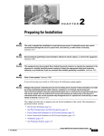
Preparing for Installation
2-1
Electrostatic Discharge 2-2
Preventing Electrostatic Discharge Damage
Site Power Requirements and Heat Dissipation
2-3
Power Connection Guidelines for DC-Powered Systems
Calculating DC Input Current 2-9
2-9
Site-Planning Checklist
3
2-3
Power Connection Guidelines for AC-Powered Systems
Ventilation 2-10
Calculating System Heat Dissipation
CHAPTER
2-2
2-11
2-11
Installing the Switch in a Rack
3-1
Checking the Shipping Container Contents
3-1
Rack-Mounting the Switch 3-2
Required Installation Tools 3-2
Rack-Mounting Catalyst 4500 E-series Switches
3-3
System Ground Connection Guidelines 3-5
Parts and Required Tools 3-6
Connecting System Ground and Power 3-6
CHAPTER
4
Removing and Replacing FRUs
4-1
Removing and Replacing the Power Supply 4-2
Required Tools 4-4
Removing an AC-Input Power Supply 4-4
Installing an AC-Input Power Supply 4-6
Removing a DC-Input Power Supply 4-8
Required Tools 4-8
Removal Procedure 4-8
Installing a DC-Input Power Supply 4-11
Required Tools 4-11
Installation Procedure 4-12
Removing and Replacing the Chassis Fan Assembly
Required Tools 4-13
Removing the Fan Assembly 4-13
Installing the Fan Assembly 4-14
4-13
Catalyst 4500 E-Series Switches Installation Guide
iv
OL-13972-01
Contents
Verifying the Installation
4-15
Replacing Backplane Modules 4-15
Verify the New Modules 4-18
Supervisor Memory Upgrade 4-19
Tools and Equipment Needed 4-19
Removing Memory 4-19
Installing SDRAM MiniDIMMs 4-21
CHAPTER
5
Troubleshooting
5-1
System Boot Verification
5-2
Using LEDs to Identify Startup Problems
System Messages
5-2
5-4
Troubleshooting with Software
5-4
Troubleshooting the Power Supply 5-4
System Messages and Power Problems
Useful CLI Commands 5-5
Power Supply Mixing 5-6
Troubleshooting the Fan Assembly 5-6
System Messages and Fan Problems
Useful CLI Commands 5-7
Troubleshooting Backplane Modules
5-5
5-7
5-7
Troubleshooting Switching Modules 5-8
System Messages and Switching Modules
Useful CLI Commands 5-9
5-9
Troubleshooting Supervisor Engines 5-10
System Messages and Supervisor Engines 5-10
Useful CLI Commands 5-12
Standby Supervisor Engine Problems 5-12
Switch Self-reset 5-13
Ports 1/2 and 2/2 Do Not Function 5-13
Packet Loss 5-13
Some Problems and Solutions 5-14
Module Not Online 5-14
Interface Problems 5-15
Workstation Is Unable to Log In to the Network
NIC Compatibility Issues 5-16
Interface Is in Errdisable 5-16
Faulty Supervisor Engine 5-16
5-15
Catalyst 4500 E-Series Switches Installation Guide
OL-13972-01
v
Contents
Boot Problems
5-17
Contacting the Cisco Technical Assistance Center
Serial Numbers 5-19
APPENDIX
A
Specifications
5-18
A-1
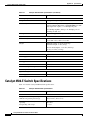
Catalyst 4503-E Switch Specifications
A-1
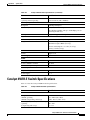
Catalyst 4506-E Switch Specifications
A-2
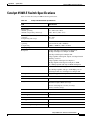
Catalyst 4507R-E Switch Specifications
A-3
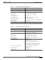
Catalyst 4510R-E Switch Specifications
A-5
Catalyst 4500 Power Supplies
A-6
APPENDIX
B
Repacking a Switch
APPENDIX
C
Initial Configuration for the Switch
B-1
Connecting to the Switch
C-1
C-2
Starting the Terminal-Emulation Software
Connecting to a Power Source
C-2
C-2
Entering the Initial Configuration Information C-3
IP Settings C-3
Performing the Initial Configuration C-3
APPENDIX
D
Module Overview and Specifications
Catalyst 4500 Series Switches
D-1
D-1
Catalyst 4500 E-Series Switches
D-1
Supervisor Engines D-1
Front-Panel Components D-3
Ethernet Management Port D-4
Console Port D-4
Supervisor Memory D-4
Switching Modules D-4
WS-X4606-X2-E D-5
WS-X4648-RJ45V-E D-5
WS-X4648-RJ45V+E D-6
Switching Module LEDs D-7
Hot-Swapping Feature
D-8
INDEX
Catalyst 4500 E-Series Switches Installation Guide
vi
OL-13972-01
Preface
This preface describes the audience,organization,and conventions ofthe Catalyst4500 E-Series
Switches Installation G uide and provides inform ation on how to obtain related docum entation and
technicalassistance.
Audience
O nly trained and qualified service personnel(as defined in IEC 60950 and A S/N ZS3260)should install,
replace,orservice the equipm ent.
Organization
This guide is organized as follow s:
Chapter
Title
Description
Chapter1
ProductO verview
D escribes the hardw are features,com ponents,interfaces,
and functionality ofthe Catalyst4500 E-series sw itches.
Chapter2
Preparing for
Installation
D escribeshow to prepare yoursite forthe installation ofthe
sw itch.
Chapter3
Installing the Sw itch
in a Rack
D escribes how to installthe Catalyst4500 E-series
sw itches.
Chapter4
Rem oving and
Replacing FRU s
D escribeshow to rem ove and replace field-replaceable units
(FRU s).
Chapter5
Troubleshooting
Provides troubleshooting guidelines forthe initialhardw are
installation and suggests steps to help isolate and resolve
problem s.
A ppendix A
Specifications
Lists the cable and technicalspecifications ofthe
Catalyst4500 E-series sw itches.
A ppendix B
Repacking a Sw itch
Provides instructions forrepacking yourCatalyst4500
E-series sw itch in the eventthatyou have to return itto the
factory.
Catalyst 4500 E-Series Switches Installation Guide
OL-13972-01
vii
Preface
Related Documentation
Chapter
Title
Description
A ppendix C
InitialConfiguration
forthe Sw itch
Provides a very m inim alconfiguration.Forfull
configuration offeatures and interfaces,referto the
softw are configuration guide foryoursoftw are release.
A ppendix D
M oduleO verview and Provides specifications and otherinform ation aboutthe
Catalyst4500 E-series sw itching m odules.
Specifications
Related Documentation
Referto the follow ing docum ents foradditionalCatalyst4500 series and Catalyst4500 E-series
inform ation:
•
Catalyst 4500 Series Module Installation Guide at
http://www.cisco.com/en/US/docs/switches/lan/catalyst4500/hardware/module/guide/
mod_inst.html
for information about individual switching modules and supervisors not discussed in this
publication.
•
Regulatory Compliance and Safety Information for the Catalyst 4500 Series Switches at
http://www.cisco.com/en/US/docs/switches/lan/catalyst4500/hardware/regulatory/compliance/
78_13233.html
•
The release note appropriate to your software version. Release notes are at:
http://www.cisco.com/en/US/products/hw/switches/ps4324/prod_release_notes_list.html
•
The software configuration guide appropriate to your software version. Software configuration
guides are at:
http://www.cisco.com/en/US/products/hw/switches/ps4324/products_installation_and_configurati
on_guides_list.html
•
The command reference appropriate to your software version. Command references are at:
http://www.cisco.com/en/US/products/hw/switches/ps4324/prod_command_reference_list.html
•
The system message guide appropriate to your software version. System message guides are at:
http://www.cisco.com/en/US/products/hw/switches/ps4324/products_system_message_guides_list
.html
•
There are a number of installation notes and technical tips available for this switch. The top level
Catalyst 4500 and Catalyst 4500-E documentation and technical support page is at
http://www.cisco.com/en/US/products/hw/switches/ps4324/tsd_products_support_
series_home.html
Conventions
This docum entuses the follow ing conventions:
Convention
Description
boldface font
Com m ands and keyw ords are in boldface.
italic font
A rgum ents forw hich you supply values are in italics.
[ ]
Elem ents in square brackets are optional.
Catalyst 4500 E-Series Switches Installation Guide
viii
OL-13972-01
Preface
Conventions
Convention
Description
{ x |y |z }
A lternative keyw ords are grouped in braces and separated by verticalbars.
[x |y |z ]
O ptionalalternative keyw ords are grouped in brackets and separated by
verticalbars.
string
A nonquoted setofcharacters.D o notuse quotation m arks around the
string,because the string w illinclude the quotation m arks.
screen
font
boldface screen
Term inalsessions and inform ation thatthe system displays are in screen
font.
Inform ation thatyou m ustenteris show n in boldface
screen
font.
font
italic screen font
A rgum ents forw hich you supply values are in italic screen font.
Ctrl-
Ctrl-representsthe key labeled Control— forexam ple,the key com bination
C trl-D m eans to hold dow n the Controlkey w hile you press the D key.
< >
Characters thatdo notprint,such as passw ords,are show n w ithin angle
brackets.
N otes use the follow ing conventions:
Note
Means reader take note. Notes contain helpful suggestions or references to material not covered in the
publication.
Cautions use the follow ing conventions:
Caution
M eans reader be careful.In this situation,you m ightdo som ething thatcould resultin
equipm entdam age orloss ofdata.
Catalyst 4500 E-Series Switches Installation Guide
OL-13972-01
ix
Preface
Conventions
Warnings use the following conventions:
Warning
IMPORTANT SAFETY INSTRUCTIONS
This warning symbol means danger. You are in a situation that could cause bodily injury. Before you
work on any equipment, be aware of the hazards involved with electrical circuitry and be familiar
with standard practices for preventing accidents. Use the statement number provided at the end of
each warning to locate its translation in the translated safety warnings that accompanied this
device. Statement 1071
SAVE THESE INSTRUCTIONS
Waarschuwing
BELANGRIJKE VEILIGHEIDSINSTRUCTIES
Dit waarschuwingssymbool betekent gevaar. U verkeert in een situatie die lichamelijk letsel kan
veroorzaken. Voordat u aan enige apparatuur gaat werken, dient u zich bewust te zijn van de bij
elektrische schakelingen betrokken risico's en dient u op de hoogte te zijn van de standaard
praktijken om ongelukken te voorkomen. Gebruik het nummer van de verklaring onderaan de
waarschuwing als u een vertaling van de waarschuwing die bij het apparaat wordt geleverd, wilt
raadplegen.
BEWAAR DEZE INSTRUCTIES
Varoitus
TÄRKEITÄ TURVALLISUUSOHJEITA
Tämä varoitusmerkki merkitsee vaaraa. Tilanne voi aiheuttaa ruumiillisia vammoja. Ennen kuin
käsittelet laitteistoa, huomioi sähköpiirien käsittelemiseen liittyvät riskit ja tutustu
onnettomuuksien yleisiin ehkäisytapoihin. Turvallisuusvaroitusten käännökset löytyvät laitteen
mukana toimitettujen käännettyjen turvallisuusvaroitusten joukosta varoitusten lopussa näkyvien
lausuntonumeroiden avulla.
SÄILYTÄ NÄMÄ OHJEET
Attention
IMPORTANTES INFORMATIONS DE SÉCURITÉ
Ce symbole d'avertissement indique un danger. Vous vous trouvez dans une situation pouvant
entraîner des blessures ou des dommages corporels. Avant de travailler sur un équipement, soyez
conscient des dangers liés aux circuits électriques et familiarisez-vous avec les procédures
couramment utilisées pour éviter les accidents. Pour prendre connaissance des traductions des
avertissements figurant dans les consignes de sécurité traduites qui accompagnent cet appareil,
référez-vous au numéro de l'instruction situé à la fin de chaque avertissement.
CONSERVEZ CES INFORMATIONS
Warnung
WICHTIGE SICHERHEITSHINWEISE
Dieses Warnsymbol bedeutet Gefahr. Sie befinden sich in einer Situation, die zu Verletzungen führen
kann. Machen Sie sich vor der Arbeit mit Geräten mit den Gefahren elektrischer Schaltungen und
den üblichen Verfahren zur Vorbeugung vor Unfällen vertraut. Suchen Sie mit der am Ende jeder
Warnung angegebenen Anweisungsnummer nach der jeweiligen Übersetzung in den übersetzten
Sicherheitshinweisen, die zusammen mit diesem Gerät ausgeliefert wurden.
BEWAHREN SIE DIESE HINWEISE GUT AUF.
Catalyst 4500 E-Series Switches Installation Guide
x
OL-13972-01
Preface
Conventions
Avvertenza
IMPORTANTI ISTRUZIONI SULLA SICUREZZA
Questo simbolo di avvertenza indica un pericolo. La situazione potrebbe causare infortuni alle
persone. Prima di intervenire su qualsiasi apparecchiatura, occorre essere al corrente dei pericoli
relativi ai circuiti elettrici e conoscere le procedure standard per la prevenzione di incidenti.
Utilizzare il numero di istruzione presente alla fine di ciascuna avvertenza per individuare le
traduzioni delle avvertenze riportate in questo documento.
CONSERVARE QUESTE ISTRUZIONI
Advarsel
VIKTIGE SIKKERHETSINSTRUKSJONER
Dette advarselssymbolet betyr fare. Du er i en situasjon som kan føre til skade på person. Før du
begynner å arbeide med noe av utstyret, må du være oppmerksom på farene forbundet med
elektriske kretser, og kjenne til standardprosedyrer for å forhindre ulykker. Bruk nummeret i slutten
av hver advarsel for å finne oversettelsen i de oversatte sikkerhetsadvarslene som fulgte med denne
enheten.
TA VARE PÅ DISSE INSTRUKSJONENE
Aviso
INSTRUÇÕES IMPORTANTES DE SEGURANÇA
Este símbolo de aviso significa perigo. Você está em uma situação que poderá ser causadora de
lesões corporais. Antes de iniciar a utilização de qualquer equipamento, tenha conhecimento dos
perigos envolvidos no manuseio de circuitos elétricos e familiarize-se com as práticas habituais de
prevenção de acidentes. Utilize o número da instrução fornecido ao final de cada aviso para
localizar sua tradução nos avisos de segurança traduzidos que acompanham este dispositivo.
GUARDE ESTAS INSTRUÇÕES
¡Advertencia!
INSTRUCCIONES IMPORTANTES DE SEGURIDAD
Este símbolo de aviso indica peligro. Existe riesgo para su integridad física. Antes de manipular
cualquier equipo, considere los riesgos de la corriente eléctrica y familiarícese con los
procedimientos estándar de prevención de accidentes. Al final de cada advertencia encontrará el
número que le ayudará a encontrar el texto traducido en el apartado de traducciones que acompaña
a este dispositivo.
GUARDE ESTAS INSTRUCCIONES
Varning!
VIKTIGA SÄKERHETSANVISNINGAR
Denna varningssignal signalerar fara. Du befinner dig i en situation som kan leda till personskada.
Innan du utför arbete på någon utrustning måste du vara medveten om farorna med elkretsar och
känna till vanliga förfaranden för att förebygga olyckor. Använd det nummer som finns i slutet av
varje varning för att hitta dess översättning i de översatta säkerhetsvarningar som medföljer denna
anordning.
SPARA DESSA ANVISNINGAR
Catalyst 4500 E-Series Switches Installation Guide
OL-13972-01
xi
Preface
Conventions
Catalyst 4500 E-Series Switches Installation Guide
xii
OL-13972-01
Preface
Conventions
Aviso
INSTRUÇÕES IMPORTANTES DE SEGURANÇA
Este símbolo de aviso significa perigo. Você se encontra em uma situação em que há risco de lesões
corporais. Antes de trabalhar com qualquer equipamento, esteja ciente dos riscos que envolvem os
circuitos elétricos e familiarize-se com as práticas padrão de prevenção de acidentes. Use o
número da declaração fornecido ao final de cada aviso para localizar sua tradução nos avisos de
segurança traduzidos que acompanham o dispositivo.
GUARDE ESTAS INSTRUÇÕES
Advarsel
VIGTIGE SIKKERHEDSANVISNINGER
Dette advarselssymbol betyder fare. Du befinder dig i en situation med risiko for
legemesbeskadigelse. Før du begynder arbejde på udstyr, skal du være opmærksom på de
involverede risici, der er ved elektriske kredsløb, og du skal sætte dig ind i standardprocedurer til
undgåelse af ulykker. Brug erklæringsnummeret efter hver advarsel for at finde oversættelsen i de
oversatte advarsler, der fulgte med denne enhed.
GEM DISSE ANVISNINGER
Catalyst 4500 E-Series Switches Installation Guide
OL-13972-01
xiii
Preface
Conventions
Catalyst 4500 E-Series Switches Installation Guide
xiv
OL-13972-01
Preface
Obtaining Documentation and Submitting a Service Request
Obtaining Documentation and Submitting a Service Request
For information on obtaining documentation, submitting a service request, and gathering additional
information, see the monthly What’s New in Cisco Product Documentation, which also lists all new and
revised Cisco technical documentation, at:
http://www.cisco.com/en/US/docs/general/whatsnew/whatsnew.html
Subscribe to the What’s New in Cisco Product Documentation as a Really Simple Syndication (RSS) feed
and set content to be delivered directly to your desktop using a reader application. The RSS feeds are a free
service and Cisco currently supports RSS version 2.0.
Catalyst 4500 E-Series Switches Installation Guide
OL-13972-01
xv
Preface
Obtaining Documentation and Submitting a Service Request
Catalyst 4500 E-Series Switches Installation Guide
xvi
OL-13972-01
CH A P T E R
1
Product Overview
This chapter provides an overview of the features and components of the Catalyst 4500 E-series
switches. The Catalyst 4500 E-series switches are the Catalyst 4503-E switch, the Catalyst 4506-E
switch, the Catalyst 4507R-E switch, and the Catalyst 4510R-E switch. The information is presented in
these major sections:
•
Switch Features, page 1-1
•
Supervisor Engines, page 1-16
•
Fan Assembly, page 1-24
•
Power Supplies, page 1-25
•
System Architecture, page 1-31
Switch Features
The following sections describe the features of the Catalyst 4500 E-series switches:
•
Power Redundancy, page 1-1
•
Catalyst 4503-E Switch Features, page 1-2
•
Catalyst 4506-E Switch Features, page 1-5
•
Supervisor Engine Redundancy, page 1-8
•
Catalyst 4507R-E Switch Features, page 1-9
•
Catalyst 4510R-E Switch Features, page 1-13
Power Redundancy
All Catalyst 4500-E switches offer 1+1 power redundancy, so that in the event of a power interruption
the switch can still operate using power from another circuit. The power supplies can also run in a
combined mode so that chassis can have power from both supplies at once. You will need to use the
power redundancy-mode command to configure combined mode. Redundant mode is the default.
Catalyst 4500-E switches support power supply redundancy only between power supplies of equal
wattage and type. A mix of power supplies is not supported. The second power supply recognized is
placed into err-disable mode.
Catalyst 4500 E-Series Switches Installation Guide
OL-13972-01
1-1
Chapter 1
Product Overview
Switch Features
A more detailed discussion of power redundancy is in the Environmental Monitoring and Power
Management chapter of the software configuration guide. Refer to the appropriate guide for your
software release.
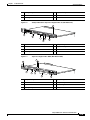
Catalyst 4503-E Switch Features
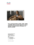
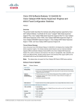
The Catalyst 4503-E switch (see Figure 1-1) is a three-slot switch designed for high-performance
high-density wiring closet applications.
Figure 1-1
Catalyst 4503-E Switch (Front View)
4
3
4503
231362
2
1
1
Fan assembly
3
Supervisor engine (Slot 1)
2
Switching modules (Slots 2 and 3)
4
Power supplies
The Catalyst 4503-E switch supports the Supervisor Engine II+, Supervisor Engine II+TS, Supervisor
Engine II+10GE, Supervisor Engine IV, Supervisor Engine V, Supervisor Engine V-10GE, and
Supervisor Engine 6-E. The supervisor engine has a nonblocking, full-duplex, switching fabric that
provides connections between the supervisor engine and the switching modules. Some supervisor
engines use SFP modules for Gigabit Ethernet connections, or X2 modules for 10-Gigabit Ethernet
connections. Refer to the installation note for your supervisor engine for more details on these modules.
Slot 1 is reserved for the supervisor engine only, which provides switching, local and remote
management, and switch-status monitoring. Slots 2 and 3 are available for switching modules. The
chassis will support up to 24 Gbps per slot for slots 2 and 3, for a maximum of 116 ports with a
Supervisor Engine II+TS, or 96 ports and 2 uplinks for other supervisors.
Catalyst 4500 E-Series Switches Installation Guide
1-2
OL-13972-01
Chapter 1
Product Overview
Switch Features
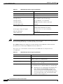
Table 1-1 describes the features of the Catalyst 4503-E switch.
Table 1-1
Features of the Catalyst 4503 Switch
Feature
Ethernet speeds
Description
•
Ethernet (10BASE-T) interface to workstations and repeaters
•
Fast Ethernet (100BASE-T) interface to workstations, servers, switches,
and routers
Note
Standard equipment
Power supplies
Supervisor engine
support
•
Gigabit Ethernet (1000BASE-T and 1000BASE-X) interfaces for
backbone interconnection of high-performance workstations, servers,
switches and routers
•
10-Gigabit Ethernet interfaces for backbone interconnection of
high-performance switches and routers
•
Three-slot modular chassis with one slot reserved for a supervisor engine
and two slots for switching modules
•
One hot-swappable fan assembly
•
Two power supply bays
•
Supports a 1000 W, 1300 W, 1400 W, 2800 W, or 4200W AC-input power
supply or a 1400 W DC-input single input or triple-input power supply1
•
Optional redundant power supply
•
Supports the WS-X4013+, WS-X4013+TS, WS-X4013+10GE,
WS-X4515, WS-X4516, WS-X4516-10GE, and WS-X45-Sup6-E
supervisor engines
•
Holds the ASIC-based forwarding engine (data path) and the management
processor and software (control path)
•
Features interface monitoring, environmental status, and SNMP and
console/Telnet interface
Note
Switching module
support
Autonegotiation of link speed on each 10/100 port allows migration to
100BASE-T from a 10BASE-T installed base.
Packets are not forwarded while the module is removed; a system
reboot occurs when a supervisor engine is reinserted.
•
24-port 10/100BASE-TX Fast Ethernet switching module
(WS-X4124-RJ45)
•
24-port 100BASE-FX Fast Ethernet switching module
(WS-X4124-FX-MT)
•
48-port 100BASE-FX Fast Ethernet switching module
(WS-X4148-FX-MT)
•
48-port 100BASE-LX10 Fast Ethernet switching module
(WS-X4148-FE-LX-MT)
•
48-port 10/100-Mbps Fast Ethernet switching module (WS-X4148-RJ)
•
48-port 100BASE-BX10-D Fast Ethernet switching module
(WS-X4148-FE-BD-LC)
•
48-port 10/100-Mbps Fast Ethernet switching module (WS-X4148-RJ21)
Catalyst 4500 E-Series Switches Installation Guide
OL-13972-01
1-3
Chapter 1
Product Overview
Switch Features
Table 1-1
Features of the Catalyst 4503 Switch (continued)
Feature
Switching module
support (continued)
Description
•
48-port 100BASE-X Fast Ethernet switching module
(WS-X4248-FE-SFP)
•
24-port IEEE 802.3af-compliant PoE 10/100BASE-TX switching module
(WS-X4224-RJ45V)
•
48-port IEEE 802.3af compliant PoE 10/100BASE-TX RJ-45 switching
module (WS-X4248-RJ45V)
•
48 port IEEE 802.3af compliant PoE 10/100BASE-TX RJ-21 switching
module (WS-X4248-RJ21V)
•
32-port 10/100-Mbps Fast Ethernet plus 2-port Gigabit Ethernet switching
module (WS-X4232-GB-RJ)
•
32-port 10/100-Mbps Fast Ethernet plus 2-port 1000BASE-X Layer 3
Gigabit Ethernet routing module (WS-X4232-L3)
•
32-port 10/100-Mbps Fast Ethernet switching module with modular
uplink support (WS-X4232-RJ-XX)
– 4-port MT-RJ uplink module (WS-U4504-FX-MT) (optional)
•
2-port Gigabit Ethernet switching module (WS-X4302-GB)
•
6-port 1000BASE-X Gigabit Ethernet switching module (WS-X4306-GB)
•
6-port Gigabit Ethernet switching module (WS-X4506-GB-T)
•
18-port Gigabit Ethernet switching module (WS-X4418-GB)
•
24-port10/100/1000BA SE-T G igabitEthernetsw itching m odule
(WS-X4424-GB-RJ45)
•
48-port Gigabit Ethernet 1000 BASE LX (SPF) switching module
(WS-X4448-GB-LX)
•
48-port10/100/1000BA SE-T G igabitEthernetsw itching m odule
(WS-X4448-GB-RJ45)
•
24-port IEEE 802.3af-compliant PoE 10/100/1000BASE-T RJ-45
switching module (WS-X4524-GB-RJ45V)
•
48-port10/100/1000BA SE-T G igabitEthernetsw itching m odule
(WS-X4548-GB-RJ45)
•
48-port Gigabit Ethernet switching module (WS-X4448-GB-SFP)
•
48-port IEEE 802.3af compliant PoE 10/100/1000BASE-T G igabit
Ethernetsw itching m odule (WS-X4548-GB-RJ45V)
•
Backplane channel module (WS-X4019)
•
6-port 10GbE X2 switching module (WS-X4606-X2-E)
•
48-port 802.3af PoE 10/100/1000 RJ45 switching module
(WS-X4648-RJ45V-E)
•
48-port Premium PoE 10/100/1000 (RJ45) switching module
(WS-X4648-RJ45V+E)
1. You will need to configure the 1400 W DC input current as appropriate for the model of switch. Refer to Appendix A,
“Specifications.”
Catalyst 4500 E-Series Switches Installation Guide
1-4
OL-13972-01
Chapter 1
Product Overview
Switch Features
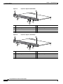
Catalyst 4506-E Switch Features
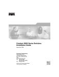
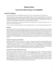
The Catalyst 4506-E switch (see Figure 1-2) is a six-slot switch designed for high-performance
high-density wiring closet applications.
Figure 1-2
Catalyst 4506-E Switch (Front View)
4
3
4506
231363
2
1
1
Fan assembly
3
Supervisor engine (Slot 1)
2
Switching modules (Slots 2 to 6)
4
Power supplies
The Catalyst 4506-E switch supports the Supervisor Engine II+, Supervisor Engine II+10GE, Supervisor
Engine IV, Supervisor Engine V, Supervisor Engine V-10GE, and Supervisor Engine 6-E. The supervisor
engine has a nonblocking, full-duplex, switching fabric that provides connections between the
supervisor engine and the switching modules. Some supervisor engines use SFP modules for Gigabit
Ethernet connections, or X2 modules for 10-Gigabit Ethernet connections. Refer to the installation note
for your supervisor engine for more details on these modules.
Slot 1 is reserved for the supervisor engine only, which provides switching, local and remote
management, and switch-status monitoring. Slots 2 through 6 are available for switching modules. The
chassis will support up to 24 Gbps per slot for slots 2 through 6, for a maximum of 240 ports and 2
uplinks.
Catalyst 4500 E-Series Switches Installation Guide
OL-13972-01
1-5
Chapter 1
Product Overview
Switch Features
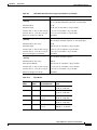
Table 1-2 describes the features of the Catalyst 4506-E switch.
Table 1-2
Features of the Catalyst 4506-E Switch
Feature
Ethernet speeds
Description
•
Ethernet (10BASE-T) interface to workstations and repeaters
•
Fast Ethernet (100BASE-T) interface to workstations, servers, switches,
and routers
Note
Standard equipment
Power supplies
Supervisor engine
support
•
Gigabit Ethernet (1000BASE-T and 1000BASE-X) interfaces for
backbone interconnection of high-performance workstations, servers,
switches and routers
•
10-Gigabit Ethernet interfaces for backbone interconnection of
high-performance switches and routers
•
Six-slot modular chassis with one slot reserved for a supervisor engine
and five slots for switching modules
•
One hot-swappable fan assembly
•
Two power supply bays
•
Supports a 1000 W, 1300 W, 1400 W, 2800 W, or 4200 W AC-input
power supply or a 1400 W DC-input single or triple-input power supply1
•
Optional redundant power supply
•
Supports the WS-X4013+, WS-X4515, WS-X4516, WS-X4516-10GE,
and WS-X45-Sup6-E Supervisor Engines
•
Holds the ASIC-based forwarding engine (data path) and the
management processor and software (control path)
•
Features interface monitoring, environmental status, and SNMP and
console/Telnet interface
Note
Switching module
support
Autonegotiation of link speed on each 10/100 port allows migration
to 100BASE-T from a 10BASE-T installed base.
Packets are not forwarded while the module is removed; a system
reboot occurs when a supervisor engine is reinserted.
•
24-port 10/100BASE-TX Fast Ethernet switching module
(WS-X4124-RJ45)
•
24-port 100BASE-FX Fast Ethernet switching module
(WS-X4124-FX-MT)
•
48-port 100BASE-FX Fast Ethernet switching module
(WS-X4148-FX-MT)
•
48-port 100BASE-LX10 Fast Ethernet switching module
(WS-X4148-FE-LX-MT)
•
48-port 10/100-Mbps Fast Ethernet switching module (WS-X4148-RJ)
•
48-port 100BASE-BX10-D Fast Ethernet switching module
(WS-X4148-FE-BD-LC)
Catalyst 4500 E-Series Switches Installation Guide
1-6
OL-13972-01
Chapter 1
Product Overview
Switch Features
Table 1-2
Features of the Catalyst 4506-E Switch (continued)
Feature
Switching module
support (continued)
Description
•
48-port 10/100-Mbps Fast Ethernet switching module
(WS-X4148-RJ21)
•
24-port IEEE 802.3af-compliant PoE 10/100BASE-TX switching
module (WS-X4224-RJ45V)
•
48-port IEEE 802.3af compliant PoE 10/100BASE-TX RJ-45 switching
module (WS-X4248-RJ45V)
•
48-port 100BASE-X Fast Ethernet switching module
(WS-X4248-FE-SFP)
•
48 port IEEE 802.3af compliant PoE 10/100BASE-TX RJ-21 switching
module (WS-X4248-RJ21V)
•
32-port 10/100-Mbps Fast Ethernet plus 2-port Gigabit Ethernet
switching module (WS-X4232-GB-RJ)
•
32-port 10/100-Mbps Fast Ethernet plus 2-port 1000BASE-X Layer 3
Gigabit Ethernet routing module (WS-X4232-L3)
•
32-port 10/100-Mbps Fast Ethernet switching module with modular
uplink support (WS-X4232-RJ-XX)
•
2-port Gigabit Ethernet switching module (WS-X4302-GB)
•
6-port 1000BASE-X Gigabit Ethernet switching module
(WS-X4306-GB)
•
6-port Gigabit Ethernet switching module (WS-X4506-GB-T)
•
18-port Gigabit Ethernet switching module (WS-X4418-GB)
•
24-port10/100/1000BA SE-T G igabitEthernetsw itching m odule
(WS-X4424-GB-RJ45)
•
48-port Gigabit Ethernet 1000 BASE LX (SPF) switching module
(WS-X4448-GB-LX)
•
48-port10/100/1000BA SE-T G igabitEthernetsw itching m odule
(WS-X4448-GB-RJ45)
•
24-port IEEE 802.3af-compliant PoE 10/100/1000BASE-T RJ-45
switching module (WS-X4524-GB-RJ45V)
•
48-port10/100/1000BA SE-T G igabitEthernetsw itching m odule
(WS-X4548-GB-RJ45)
•
48-port Gigabit Ethernet switching module (WS-X4448-GB-SFP)
•
48-port IEEE 802.3af compliant PoE 10/100/1000BASE-T G igabit
Ethernetsw itching m odule (WS-X4548-GB-RJ45V)
•
Backplane channel module (WS-X4019)
•
6-port 10GbE X2 switching module (WS-X4606-X2-E)
•
48-port 802.3af PoE 10/100/1000 RJ45 switching module
(WS-X4648-RJ45V-E)
•
48-port Premium PoE 10/100/1000 RJ45 switching module
(WS-X4648-RJ45V+E)
Catalyst 4500 E-Series Switches Installation Guide
OL-13972-01
1-7
Chapter 1
Product Overview
Switch Features
1. You will need to configure the 1400 W DC input current as appropriate for the model of switch. Refer to Appendix A,
“Specifications.”
Supervisor Engine Redundancy
The Catalyst 4507R-E and Catalyst 4510R-E switches support supervisor engine redundancy.
Redundancy allows a second supervisor engine to take over if the active supervisor engine fails.
With supervisor engine redundancy enabled, if the active supervisor engine fails or if a manual
switchover is performed, the redundant supervisor engine becomes the active supervisor engine. The
redundant supervisor engine is automatically initialized with the startup configuration of the active
supervisor engine. Depending on the configuration this shortens the switchover time from 30 seconds or
longer in Route Processor Redundancy (RPR) mode, to less than a second in Stateful Switch Over (SSO)
mode.
In addition to the reduced switchover time, supervisor engine redundancy supports these:
•
Online insertion and removal (OIR) of the redundant supervisor engine
Supervisor engine redundancy allows OIR of the redundant supervisor engine for maintenance.
When the redundant supervisor engine is inserted, the active supervisor engine detects it. The
redundant supervisor engine boots into a partially initialized state in RPR mode and a fully
initialized state in SSO mode.
•
Software upgrade
Load the new image on the redundant supervisor engine and conduct a switchover. This minimizes
downtime during software changes on the supervisor engine.
When power is first applied to a switch, the supervisor engine that boots first becomes the active
supervisor engine and remains active until a switchover occurs.
Redundancy requires that both supervisor engines in the chassis are of the same supervisor engine
model, and that they use the same Cisco IOS software image.
For more detail about redundancy, refer to the Configuring Supervisor Engine Redundancy Using RPR
and SSO chapter of the software configuration guide for your software release.
Catalyst 4500 E-Series Switches Installation Guide
1-8
OL-13972-01
Chapter 1
Product Overview
Switch Features
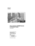
Catalyst 4507R-E Switch Features
The Catalyst 4507R-E switch (see Figure 1-3) is a seven-slot switch designed for high-performance
high-density wiring closet applications.
Figure 1-3
Catalyst 4507R-E Switch (Front View)
4
4506
3
231952
2
1
1
Fan Tray
3
Supervisor engines (primary in slot 3,
secondary in slot 4)
2
Switching modules (slots 1, 2, 5, 6, 7)
4
Power supplies
The Catalyst 4507R-E switch supports the Supervisor Engine II+, Supervisor Engine IV, Supervisor
Engine V, Supervisor Engine V-10GE, and Supervisor Engine 6-E. The supervisor engine has two
Gigabit Ethernet ports and a nonblocking, full-duplex, switching fabric that provides connections
between the supervisor engine and the switching modules. Some supervisor engines use SFP modules
for Gigabit Ethernet connections or X2 modules for 10-Gigabit Ethernet connections. Refer to the
installation note for your supervisor engine for more details on these modules.
Slot 3 is reserved for the supervisor engine only, which provides switching, local and remote
management, and switch-status monitoring. Slot 4 is reserved for a redundant supervisor engine only.
Slots 1, 2, 5, 6, and 7 are available for switching modules and provide 24 Gbps per slot for a maximum
of 240 ports and 4 uplinks.
Catalyst 4500 E-Series Switches Installation Guide
OL-13972-01
1-9
Chapter 1
Product Overview
Switch Features
Table 1-3 describes the features of the Catalyst 4507R-E switch.
Table 1-3
Features of the Catalyst 4507R-E Switch
Feature
Ethernet speeds
Description
•
Ethernet (10BASE-T) interface to workstations and repeaters
•
Fast Ethernet (100BASE-T) interface to workstations, servers, switches, and
routers
Note
Standard equipment
Power supplies
Supervisor engine
support
Autonegotiation of link speed on each 10/100 port allows migration to
100BASE-T from a 10BASE-T installed base.
•
Gigabit Ethernet (1000BASE-T and 1000BASE-X) interfaces for backbone
interconnection of high-performance switches and routers
•
10-Gigabit Ethernet interfaces for backbone interconnection of
high-performance switches and routers
•
Seven-slot modular chassis with one slot reserved for a supervisor engine,
one slot reserved for a redundant supervisor engine, and five slots for
switching modules
•
Two power supply bays
•
One hot-swappable fan assembly
•
Can support a 1000 W, 1300 W, 1400 W, 2800 W, or 4200W AC-input power
supply or a 1400 W DC-input single or triple-input power supply 1
•
Optional redundant power supply
•
Supports the WS-X4013+, WS-X4515, WS-X4516, WS-X4516-10GE, and
WS-X45-Sup6-E Supervisor Engines
•
Holds the ASIC-based forwarding engine (data path) and the management
processor and software (control path)
•
Features interface monitoring, environmental status, and SNMP and
console/Telnet interface
Note
With a single supervisor, packets are not forwarded while the module is
removed; a system reboot occurs when a supervisor engine is reinserted.
In redundant systems, removing the active supervisor causes the standby
supervisor to become active.
Catalyst 4500 E-Series Switches Installation Guide
1-10
OL-13972-01
Chapter 1
Product Overview
Switch Features
Table 1-3
Features of the Catalyst 4507R-E Switch (continued)
Feature
Switching module
support
Description
•
32-port 10/100-Mbps Fast Ethernet plus 2-port Gigabit Ethernet switching
module (WS-X4232-GB-RJ)
•
32-port 10/100-Mbps Fast Ethernet plus 2-port 1000BASE-X Layer 3
Gigabit Ethernet routing module (WS-X4232-L3)
•
32-port 10/100-Mbps Fast Ethernet switching module with modular uplink
support (WS-X4232-RJ-XX)
– 4-port MT-RJ uplink module (WS-U4504-FX-MT) (optional)
•
2-port Gigabit Ethernet switching module (WS-X4302-GB)
•
24-port 10/100BASE-TX Fast Ethernet switching module
(WS-X4124-RJ45)
•
24-port 100BASE-FX Fast Ethernet switching module (WS-X4124-FX-MT)
•
48-port 100BASE-FX Fast Ethernet switching module (WS-X4148-FX-MT)
•
48-port 100BASE-LX10 Fast Ethernet switching module
(WS-X4148-FE-LX-MT)
•
48-port 10/100-Mbps Fast Ethernet switching module (WS-X4148-RJ)
•
48-port 100BASE-BX10-D Fast Ethernet switching module
(WS-X4148-FE-BD-LC)
•
48-port 10/100-Mbps Fast Ethernet switching module (WS-X4148-RJ21)
•
48-port 100BASE-X Fast Ethernet switching module (WS-X4248-FE-SFP)
Catalyst 4500 E-Series Switches Installation Guide
OL-13972-01
1-11
Chapter 1
Product Overview
Switch Features
Table 1-3
Features of the Catalyst 4507R-E Switch (continued)
Feature
Switching module
support (continued)
Description
•
24-port IEEE 802.3af-compliant PoE 10/100BASE-TX switching module
(WS-X4224-RJ45V)
•
48-port IEEE 802.3af compliant PoE 10/100BASE-TX RJ-45 switching
module (WS-X4248-RJ45V)
•
48 port IEEE 802.3af compliant PoE 10/100BASE-TX RJ-21 switching
module (WS-X4248-RJ21V)
•
6-port 1000BASE-X Gigabit Ethernet switching module (WS-X4306-GB)
•
6-port Gigabit Ethernet switching module (WS-X4506-GB-T)
•
18-port Gigabit Ethernet switching module (WS-X4418-GB)
•
24-port10/100/1000BA SE-T G igabitEthernetsw itching m odule
(WS-X4424-GB-RJ45)
•
48-port Gigabit Ethernet 1000 BASE LX (SPF) switching module
(WS-X4448-GB-LX)
•
48-port10/100/1000BA SE-T G igabitEthernetsw itching m odule
(WS-X4448-GB-RJ45)
•
24-port IEEE 802.3af-compliant PoE 10/100/1000BASE-T RJ-45 switching
module (WS-X4524-GB-RJ45V)
•
48-port10/100/1000BA SE-T G igabitEthernetsw itching m odule
(WS-X4548-GB-RJ45)
•
48-port Gigabit Ethernet switching module (WS-X4448-GB-SFP)
•
48-port IEEE 802.3af compliant PoE 10/100/1000BASE-T G igabitEthernet
sw itching m odule (WS-X4548-GB-RJ45V)
•
6-port 10GbE X2 switching module (WS-X4606-X2-E)
•
48-port 802.3af PoE 10/100/1000 RJ45 switching module
(WS-X4648-RJ45V-E)
•
48-port Premium PoE 10/100/1000 RJ45 switching module
(WS-X4648-RJ45V+E)
1. You will need to configure the 1400 W DC input current as appropriate for the model of switch. Refer to Appendix A,
“Specifications.”
Catalyst 4500 E-Series Switches Installation Guide
1-12
OL-13972-01
Chapter 1
Product Overview
Switch Features
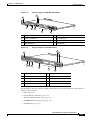
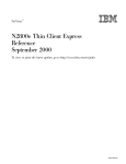
Catalyst 4510R-E Switch Features
The Catalyst 4510R-E switch (see Figure 1-4) is a ten-slot switch designed for high-performance
high-density wiring closet applications.
Figure 1-4
Catalyst 4510R-E Switch (Front View)
4
4506
3
2
S
1
2
3
4
5
6
7
8
9
10
11
12
13
14
15
16
10/100B
ASE-TX
ETHERN
ET
17
18
19
20
21
22
23
24
25
26
STATUS
1
2
3
4
5
6
7
8
9
10
11
12
13
14
15
16
27
28
29
30
31
MULTI-S
GIGABIT PEED
ETHERN
ET
ING MODULE
32 SWITCH
33
34
35
36
37
38
39
40
41
42
43
44
45
10/100B
ASE-TX
ETHERN
ET
17
18
19
20
21
22
23
24
25
26
27
28
29
30
31
MULTI-S
GIGABIT PEED
ETHERN
ET
ING MODULE
46
47
48
47
48
231953
STATU
32 SWITCH
33
34
35
36
37
38
39
40
41
42
43
44
45
46
1
2
1
1
Fan Tray
3
2
Switching modules (slots 1, 2, 3, 4, 7, 8, 9, 10) 4
Supervisor engines (primary in slot 5,
secondary in slot 6)
Power supplies
The Catalyst 4510R-E switch supports the Supervisor Engine V, Supervisor Engine V-10GE, and
Supervisor Engine 6-E. The supervisor engine has a nonblocking, full-duplex, switching fabric that
provides connections between the supervisor engine and the switching modules. Some supervisor
engines use SFP modules for Gigabit Ethernet connections, or X2 modules for 10 Gigabit Ethernet
connections. Refer to the installation note for your supervisor engine for more details on these modules.
Slot 5 is reserved for the supervisor engine only, which provides switching, local and remote
management, and switch-status monitoring. Slot 6 is reserved for a redundant supervisor engine only.
Slots 1, 2, 3, 4, 7, 8, 9, and 10 are available for switching modules and provide up to 24 Gbps per slot
Catalyst 4500 E-Series Switches Installation Guide
OL-13972-01
1-13
Chapter 1
Product Overview
Switch Features
for a maximum of 384 ports and 4 uplinks. With a Supervisor Engine 6-E, slots 8 to 10 provide 6 Gbps
per slot and all other slots provide 24 Gbps per slot. With a Supervisor Engine V or Supervisor Engine
V-10GE, all slots are 6 Gbps and E-series switching modules can not be used.
Table 1-4 describes the features of the Catalyst 4510R-E switch.
Table 1-4
Features of the Catalyst 4510R-E Switch
Feature
Ethernet speeds
Description
•
Ethernet (10BASE-T) interface to workstations and repeaters
•
Fast Ethernet (100BASE-T) interface to workstations, servers, switches, and
routers
Note
Standard equipment
Power supplies
Supervisor engine
support
Autonegotiation of link speed on each 10/100 port allows migration to
100BASE-T from a 10BASE-T installed base.
•
Gigabit Ethernet (1000BASE-T and 1000BASE-X) interfaces for backbone
interconnection of high-performance switches and routers
•
10-Gigabit Ethernet interfaces for backbone interconnection of
high-performance switches and routers
•
Ten-slot modular chassis with one slot reserved for a supervisor engine, one
slot reserved for a redundant supervisor engine, and eight slots for switching
modules
•
Two power supply bays
•
One hot-swappable fan assembly
•
Can support a 1400 W, 2800 W, or 4200 W AC-input power supply or a
1400 W DC-input single or triple-input power supply 1, 2
•
Optional redundant power supply
•
Supports the WS-X4516, WS-X4516-10GE, and WS-X45-Sup6-E
Supervisor Engines
•
Holds the ASIC-based forwarding engine (data path) and the management
processor and software (control path)
•
Features interface monitoring, environmental status, and SNMP and
console/Telnet interface
Note
With a single supervisor, packets are not forwarded while the module is
removed; a system reboot occurs when a supervisor engine is reinserted.
In redundant systems, removing the active supervisor causes the standby
supervisor to become active.
Catalyst 4500 E-Series Switches Installation Guide
1-14
OL-13972-01
Chapter 1
Product Overview
Switch Features
Table 1-4
Features of the Catalyst 4510R-E Switch (continued)
Feature
Switching module
support
Description
•
24-port 10/100BASE-TX Fast Ethernet switching module
(WS-X4124-RJ45)
•
24-port 100BASE-FX Fast Ethernet switching module (WS-X4124-FX-MT)
•
48-port 100BASE-FX Fast Ethernet switching module (WS-X4148-FX-MT)
•
48-port 100BASE-LX10 Fast Ethernet switching module
(WS-X4148-FE-LX-MT)
•
48-port 10/100-Mbps Fast Ethernet switching module (WS-X4148-RJ)
•
48-port 100BASE-BX10-D Fast Ethernet switching module
(WS-X4148-FE-BD-LC)
•
48-port 10/100-Mbps Fast Ethernet switching module (WS-X4148-RJ21)
•
24-port IEEE 802.3af-compliant PoE 10/100BASE-TX switching module
(WS-X4224-RJ45V)
•
48-port IEEE 802.3af compliant PoE 10/100BASE-TX RJ-45 switching
module (WS-X4248-RJ45V)
•
48-port 100BASE-X Fast Ethernet switching module (WS-X4248-FE-SFP)
•
48 port IEEE 802.3af compliant PoE 10/100BASE-TX RJ-21 switching
module (WS-X4248-RJ21V)
•
32-port 10/100-Mbps Fast Ethernet plus 2-port Gigabit Ethernet switching
module (WS-X4232-GB-RJ)
Catalyst 4500 E-Series Switches Installation Guide
OL-13972-01
1-15
Chapter 1
Product Overview
Supervisor Engines
Table 1-4
Features of the Catalyst 4510R-E Switch (continued)
Feature
Switching module
support (continued)
Description
•
32-port 10/100-Mbps Fast Ethernet plus 2-port 1000BASE-X Layer 3
Gigabit Ethernet routing module (WS-X4232-L3)
•
32-port 10/100-Mbps Fast Ethernet switching module with modular uplink
support (WS-X4232-RJ-XX)
– 4-port MT-RJ uplink module (WS-U4504-FX-MT) (optional)
•
2-port Gigabit Ethernet switching module (WS-X4302-GB)
•
6-port 1000BASE-X Gigabit Ethernet switching module (WS-X4306-GB)
•
6-port Gigabit Ethernet switching module (WS-X4506-GB-T)
•
18-port Gigabit Ethernet switching module (WS-X4418-GB)
•
24-port10/100/1000BA SE-T G igabitEthernetsw itching m odule
(WS-X4424-GB-RJ45)
•
48-port Gigabit Ethernet 1000 BASE LX (SPF) switching module
(WS-X4448-GB-LX)
•
48-port10/100/1000BA SE-T G igabitEthernetsw itching m odule
(WS-X4448-GB-RJ45)
•
24-port IEEE 802.3af-compliant PoE 10/100/1000BASE-T RJ-45 switching
module (WS-X4524-GB-RJ45V)
•
48-port10/100/1000BA SE-T G igabitEthernetsw itching m odule
(WS-X4548-GB-RJ45)
•
48-port Gigabit Ethernet switching module (WS-X4448-GB-SFP)
•
48-port IEEE 802.3af compliant PoE 10/100/1000BASE-T G igabitEthernet
sw itching m odule (WS-X4548-GB-RJ45V)
•
6-port 10GbE X2 switching module (WS-X4606-X2-E)
•
48-port 802.3af PoE 10/100/1000 RJ45 switching module
(WS-X4648-RJ45V-E)
•
48-port Premium PoE 10/100/1000 RJ45 switching module
(WS-X4648-RJ45V+E)
1. You will need to configure the 1400 W DC input current as appropriate for the model of switch. Refer to Appendix A,
“Specifications.”
2. 1000W AC and 1300W AC power supplies will fit and function; however, power management is cautioned and only some
configurations will have adequate power. Please refer to the Cisco Power Calculator at http://tools.cisco.com/cpc/ before
configuring these power supplies.
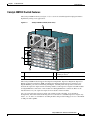
Supervisor Engines
The following supervisor engines are available for the Catalyst 4500 series and Catalyst 4500 E-series
switches:
•
Supervisor Engine II-Plus (WS-X4013+) (Figure 1-5)
•
Supervisor Engine II-Plus TS (WS-X4013+TS) (Figure 1-6)
•
Supervisor Engine II-Plus 10GE (WS-X4013+10GE) (Figure 1-7)
Catalyst 4500 E-Series Switches Installation Guide
1-16
OL-13972-01
Chapter 1
Product Overview
Supervisor Engines
Note
•
Supervisor Engine IV (WS-X4515) (Figure 1-8)
•
Supervisor Engine V (WS-X4516) (Figure 1-9)
•
Supervisor Engine V-10GE (WS-X4516-10GE) (Figure 1-10)
•
Supervisor Engine 6-E (WS-X45-Sup6-E) (Figure 1-11)
If you move a supervisor engine from a Catalyst 4500 series chassis to a Catalyst 4500-E chassis it must
use Cisco IOS Release 12.2(37)SG or later. Refer to the release note for software upgrade procedures if
needed:
http://www.cisco.com/en/US/products/hw/switches/ps4324/prod_release_note09186a0080758ff3.html
#wp305142
The Catalyst 4500 series and Catalyst 4500 E-series supervisor engines have the following features:
Table 1-5
Supervisor Engine Features
Feature
Description
Data path and control
Available on all network interfaces
Management functions
Interface monitoring
Environmental status
SNMP and console/Telnet interface
MAC addresses supported
32,768 per system (Cisco IOS only)
VLANS
Up to 4,096 VLANs with IEEE 802.1Q VLAN tagging on all ports and
VLAN Trunking Protocol (VTP)
Port aggregation
PAgP1 for 100-Mbps and 1000-Mbps EtherChannel
SNMP
Full implementation, including entity-MIB, all relevant standard MIBs,
and all relevant Cisco MIBs
RMON
The first four groups (Ethernet statistics, Alarms, Events, and History)
are on a per-port basis without an optional RMON processing module
SPAN2
Supported, which allows you to redirect traffic from any port or VLAN
to a SPAN destination port
Performance management
Information provided
Hot-swappable
Supported. On non-redundant systems, packets are not forwarded while
the supervisor engine is removed, and a system reboot occurs when a
supervisor engine is reinserted.
Gigabit Ethernet (using a
GBIC or SFP)
Includes two (four on WS-X4516-10GE and WS-X4013+10GE) Gigabit
Ethernet (1000BASE-X) interfaces for backbone interconnection of
high-performance switches and routers
10-Gigabit Ethernet
(WS-X4516-10GE,
WS-X4013+10GE and
WS-X45-Sup6-E)
Includes two 10 Gigabit Ethernet interfaces for backbone
interconnection of high-performance switches and routers
Forwarding
Layer 2, 3, and 4 forwarding (Cisco IOS only)
Catalyst 4500 E-Series Switches Installation Guide
OL-13972-01
1-17
Chapter 1
Product Overview
Supervisor Engines
Table 1-5
Supervisor Engine Features (continued)
Feature
Description
Supervisor Engine II-Plus
64 Gbps, 48 Mpps (with Catalyst 4506-E and 4507R-E, or 28-Gbps, 21
Mpps with Catalyst 4503-E) full-duplex Gigabit Ethernet switching
engine
Supervisor
Engine II-Plus TS
64 Gbps, 48 Mpps (with Catalyst 4503-E only) full-duplex Gigabit
Ethernet switching engine
Supervisor
Engine II-Plus 10GE
108 Gbps, 81 Mpps full-duplex Gigabit Ethernet switching engine
Supervisor Engine IV
64 Gbps, 48 Mpps (with Catalyst 4506-E and 4507R-E, or 28-Gbps, 21
Mpps with Catalyst 4503-E) full-duplex Gigabit Ethernet switching
engine
Supervisor Engine V
96-Gbps, 72 Mpps (with Catalyst 4510R-E, 68 Gbps, 51 Mpps with
Catalyst 4507R-E, 64 Gbps, 48 Mpps with Catalyst 4506-E, 28 Gbps,
21 Mpps with Catalyst 4503-E) full-duplex Gigabit Ethernet switching
engine
Supervisor Engine V-10GE
136-Gbps, 101 Mpps (with Catalyst 4510R-E, 68 Gbps, 51 Mpps with
Catalyst 4507R-E, 64 Gbps, 48 Mpps with Catalyst 4506-E, 28 Gbps,
21 Mpps with Catalyst 4503-E) full-duplex Gigabit Ethernet switching
engine
Supervisor Engine 6-E
320-Gbps, 250 Mpps (with Catalyst 4510R-E, 280 Gbps, 210 Mpps with
Catalyst 4507R-E, 280 Gbps, 210 Mpps with Catalyst 4506-E,
136 Gbps, 102 Mpps with Catalyst 4503-E) full-duplex Gigabit Ethernet
switching engine
1. PAgP = Port Aggregation Protocol
2. SPAN = switched port analyzer
To install the supervisor engine, refer to the procedure in the Catalyst 4500 Series Module Installation
Guide. The various supervisor engine models are shown in Figure 1-5 to Figure 1-10.
Figure 1-5
Supervisor Engine II-Plus (WS-X4013+)
7
1
UPLINK
UPLINK
STATUS
1
UPLINKS
ENABLE
D
CONSOLE
10/100 MGT
UTILIZATION
1%
FLASH
231960
2
100%
EJECT
2
3
5
RESET
6
4
1
Status LED
5
Management Port
Catalyst 4500 E-Series Switches Installation Guide
1-18
OL-13972-01
Chapter 1
Product Overview
Supervisor Engines
2
GBIC uplink ports
6
Compact flash port
3
Switch load indicators
7
Reset button
4
Console port
Figure 1-6
Catalyst 4500 Series Supervisor Engine II-Plus TS (WS-X4013+TS)
7
231961
1
2
3
5
4
6
1
Status LED
5
Management port
2
PoE status LED
6
Compact Flash port
3
Switch load indicators
7
Reset button
4
Console port
Figure 1-7
Supervisor Engine II-Plus 10GE (WS-X4013+10GE)
7
6
8
1
2
231961
EJECT
3
4
5
1
Compact flash port
5
Gigabit SFP ports
2
Switch load indicator
6
Management port
3
RESET button
7
CONSOLE port
4
10GE uplink ports
8
STATUS LED
Catalyst 4500 E-Series Switches Installation Guide
OL-13972-01
1-19
Chapter 1
Product Overview
Supervisor Engines
Figure 1-8
Supervisor Engine IV (WS-X4515)
7
1
UPLINK
UPLINK
STATUS
1
UPLINKS
ENABLE
D
CONSOLE
10/100 MGT
UTILIZATION
1%
FLASH
231960
2
100%
EJECT
2
3
5
RESET
6
4
1
Status LED
5
Management port
2
GBIC uplink ports
6
Compact flash port
3
switch load indicators
7
Reset button
4
Console port
Figure 1-9
Supervisor Engine V (WS-X4516)
7
1
UPLINK
UPLINK
STATUS
1
UPLINKS
ENABLE
D
CONSOLE
10/100 MGT
UTILIZATION
1%
FLASH
231960
2
100%
EJECT
2
3
5
RESET
6
4
1
Status LED
5
Management port
2
GBIC uplink ports
6
Compact Flash port
3
Switch load indicators
7
Reset button
4
Console port
Catalyst 4500 E-Series Switches Installation Guide
1-20
OL-13972-01
Chapter 1
Product Overview
Supervisor Engines
Figure 1-10
Supervisor Engine V-10GE (WS-X4516-10GE)
7
6
8
1
2
231961
EJECT
3
4
5
1
Compact flash port
5
Gigabit SFP ports
2
Switch load indicator
6
Management port
3
RESET button
7
CONSOLE port
4
10GE uplink ports
8
STATUS LED
Figure 1-11
Supervisor Engine 6-E (WS-X45-Sup6-E)
8
1
2 3
4
211396
9
5
6
7
1
Status LED
6
Uplink ports
2
Reset button
7
USB port
3
Active supervisor LED
8
Console port
4
Utilization LEDs
9
Management port
5
Compact flash port
For information about the connectors, LEDs, and switches located on the front panel of the supervisor
engine, see these sections:
•
LEDs, page 1-22
•
Gigabit Ethernet Uplink Ports, page 1-22
•
10-Gigabit Ethernet Uplink Ports, page 1-23
•
10/100BASE-T Management Port, page 1-23
•
CONSOLE Port, page 1-23
Catalyst 4500 E-Series Switches Installation Guide
OL-13972-01
1-21
Chapter 1
Product Overview
Supervisor Engines
•
RESET Button, page 1-24
•
Compact Flash Slot, page 1-24
LEDs
Table 1-6 describes the supervisor engine LEDs.
Table 1-6
LED
Supervisor Engine LEDs
Color/State
STATUS
UTILIZATION
Indicates the results of a series of self-tests:
Green
All diagnostic tests passed.
Red
A test failed.
Orange
System boot or diagnostic test is in progress, or two power
supplies are installed but only one is turned on.
Off
Module is disabled.
Green 1–100%
If the switch is operational, this display indicates the current
traffic load over the backplane (as an approximate percentage).
LINK
Indicates the status of the 10/100BASE-T port,
10/100/1000BASE-T or uplink ports:
Green
The link is operational.
Orange
The link is disabled by user.
Flashing orange
The power-on self-test indicates a faulty port.
Off
No signal is detected or there is a link configuration failure.
ACTIVE
(uplink port)
Description
Indicates whether the uplink port is active or not:
Green
The port is active.
Off
The port is not active.
ACTIVE
The LED to the right of the uplink ports is only used in switches
with two supervisors. The LED lights on the active supervisor.
Gigabit Ethernet Uplink Ports
The Gigabit Ethernet uplink ports operate in full-duplex mode only. GBICs have SC connectors to
interface with multimode fiber (MMF) and single-mode fiber (SMF) cable. For more information about
GBICs, refer to the Catalyst 4500 Series Module Installation Guide. Frequently updated compatibility
information for GBICs, X2s, and SFPs are in documents at:
http://www.cisco.com/en/US/products/hw/modules/ps5455/products_device_support_tables_list.html
When two Supervisor Engine Vs are present in a Catalyst 4507R-E and Catalyst 4510R-E, all four
uplinks are active on both Primary (active) and Secondary (standby) supervisor engines by default, or
two uplinks are active in a non-redundant configuration. This limits access to slot 10 on the Catalyst
4510R to ports 3 and 4 only. You can only use the 2-port Gigabit Ethernet switching module
(WS-X4302-GB) in slot 10 (flex-slot) when a Supervisor Engine V is used.
Catalyst 4500 E-Series Switches Installation Guide
1-22
OL-13972-01
Chapter 1
Product Overview
Supervisor Engines
10-Gigabit Ethernet Uplink Ports
The 10-Gigabit Ethernet uplink ports operate in full-duplex mode only, and are only on the
WS-X4516-10GE, WS-X4013+10GE, and WS-45-Sup6-E. These ports use the hot-swappable
10GBASE X2 optical transceivers. The X2s have SC connectors to interface with multimode fiber
(MMF) and single-mode fiber (SMF) cable.
On a Catalyst 4510R-E with a Supervisor Engine V-10GE, the user can use either four Gigabit Ethernet
uplinks using SFPs or two 10-Gigabit Ethernet uplinks using X2s. The user also has the option of using
the Gigabit Ethernet and 10-Gigabit Ethernet uplinks simultaneously. With this option, the tenth slot can
only support the WS-X4302-GB switching module. On a Catalyst 4507R-E, the user can use the Gigabit
Ethernet uplinks and 10-Gigabit Ethernet uplinks simultaneously.
When two Supervisor Engine V-10GEs are present in a Catalyst 4510R-E or Catalyst 4507R-E switch,
or two Supervisor Engine II-Plus 10GEs are present in a Catalyst 4507R-E, one X2 uplink is active on
both the primary (active) and secondary (standby) supervisor engines by default, or two uplinks are
active in a non-redundant configuration.
On a Catalyst 4510R-E with a Supervisor Engine 6-E, 10-Gigabit Ethernet uplinks using X2s are the
only available uplinks. Slots 8-10 are intended for Catalyst 4500 classic switching modules only and all
other slots may use classic or E-series switching modules.
When two Supervisor Engine 6-Es are present in a Catalyst 4510R-E or Catalyst 4507R-E switch, or two
Supervisor Engine II-Plus 10GEs are present in a Catalyst 4507R-E, one X2 uplink is active on both the
primary (active) and secondary (standby) supervisor engines by default, or two uplinks are active in a
non-redundant configuration.
SFP Ports
Gigabit Ethernet SFP ports operate in full-duplex mode only and are present on the WS-X4013+TS,
WS-X4516-10GE, and WS-X4013+10GE supervisors, as well as some switching modules.
WS-X45-Sup6-E supervisors can use Cisco TwinGig converters to support two SFPs per X2 uplink port,
for a maximum of 4 SFP ports per supervisor. SFP connectors vary with interface type and may use
multimode fiber (MMF), single-mode fiber (SMF) cable, or copper Ethernet cables. SFPs use LC type
fiber connectors and RJ-45 copper connectors.
10/100BASE-T Management Port
The 10/100BASE-T Management port supports emergency image recovery. The 10/100BASE-T port
supports image downloads from the ROMMON. You can use this feature when the onboard Flash
memory does not contain any IOS images, usually after all images were accidentally deleted from
onboard Flash.
CONSOLE Port
The CONSOLE port has an EIA/TIA-232 RJ-45 connector. The CONSOLE port allows you to perform
the following functions:
•
Configure the switch from the CLI
•
Monitor network statistics and errors
•
Configure SNMP agent parameters
Catalyst 4500 E-Series Switches Installation Guide
OL-13972-01
1-23
Chapter 1
Product Overview
Fan Assembly
Note
EIA/TIA-232 was known as recommended standard RS-232 before its acceptance as a standard by the
Electronic Industries Alliance (EIA) and Telecommunications Industry Association (TIA).
RESET Button
The RESET button is used to restart the switch.
Note
Use a paper clip or other small, pointed object to press the Reset button.
Compact Flash Slot
The Compact Flash slot accepts a Type 1 Compact Flash disk. You can use it for file transfer tasks such
as loading a new software image. The Compact Flash card is optional. For more information, refer to
Using the Compact Flash on the Catalyst 4500 Supervisor Engines at the following URL:
http://www.cisco.com/en/US/docs/switches/lan/catalyst4500/hardware/configuration/notes/
OL_2788.html
Fan Assembly
Note
For complete environmental specifications, including airflow requirements, see Appendix A,
“Specifications.”
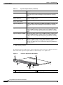
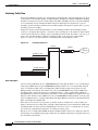
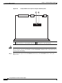
The system fan assembly provides cooling air for the internal chassis components. The fan assembly is
a tray of fans that you can insert and remove from the chassis while the system is on line. The
Catalyst 4503-E fan assembly has two fans and the Catalyst 4506-E fan assembly has four fans, the
Catalyst 4507R-E fan assembly has eight fans, and the Catalyst 4510R-E fan assembly has ten fans. The
fans draw in fresh air from one side and exhaust air on the other side. Catalyst 4506-E airflow is shown
in Figure 1-12, the others in the series are the same direction.
Caution
You must install module filler plates on unused switching module slots to ensure proper airflow.
Catalyst 4500 E-Series Switches Installation Guide
1-24
OL-13972-01
Chapter 1
Product Overview
Power Supplies
Figure 1-12
Catalyst 4506-E Airflow
231365
4506
1
1
Fan assembly
Power Supplies
Note
For detailed specifications on all Catalyst 4500 power supplies, refer to the “Catalyst 4507R-E Switch
Specifications” section on page A-3.
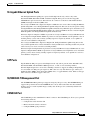
A Catalyst 4500 E-series switch can use a 1000 W, 1300 W, 1400 W, 2800 W (see Figure 1-13), or
4200 W (with two inputs, see Figure 1-14) AC-input power supply, a 1400 W DC-input power supply
with integrated PEM (see Figure 1-15), or a 1400 W DC multiple-input power supply (see Figure 1-16).
The power supplies are hot-swappable. If you have power supplies of different types installed in the two
bays, only one will be active and some power features will not be available. The power supply in the left
bay is PS1, the one in the right bay is PS2.
The AC-input power supply has a power cord that connects each power supply to the site power source.
The DC-input power supply is equipped with a input terminal block that is directly connected to the site
power wiring.
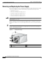
Each power supply has an ON/OFF switch that supplies power to the switch. For information on
removing and replacing power supplies, see the “Removing and Replacing the Power Supply” section
on page 4-2.
Catalyst 4500 E-Series Switches Installation Guide
OL-13972-01
1-25
Chapter 1
Product Overview
Power Supplies
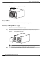
Figure 1-13
AC-Input Power Supply (All Except 4200 W)
3
231375
2
1
1
AC receptacle
2
Power switch
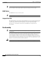
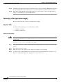
Figure 1-14
3
Captive screws
4200 W Dual Input AC Power Supply
5
100-1
20V12A
50/60
Hz
4
OUTP
{UT FAI
:
FAN OK
INPUT
1
OK
2
INPUT
2
OK
POE EN
ABLE
D
231376
3
1
100-1
20V12A
50/60
Hz
4600AC
Note
V
1
AC input 2 receptacle
4
AC input 1 receptacle
2
AC input 2 on switch
5
Captive screws
3
AC input 1 on switch
The 4200 W AC power supply should not be used in mixed-voltage configurations. All the inputs in a
chassis must be the same voltage (110 or 220 V).
Catalyst 4500 E-Series Switches Installation Guide
1-26
OL-13972-01
Chapter 1
Product Overview
Power Supplies
1400 W DC-Input Power Supply
Figure 1-16
1400 W DC Triple-Input Power Supply
231378
231377
Figure 1-15
Note
The 1400 W DC triple-input power supply is not compatible with other power supplies used on these
products, and can only be used with similar supplies. In redundant mode, the two power supplies must
have identical inputs.
The 1400 W DC input power supply (either single or triple-input) may be used with the Catalyst 4500
Series AC Power Shelf. Documentation for the Catalyst 4500 Series AC Power Shelf is at
http://www.cisco.com/en/US/docs/switches/lan/catalyst4500/hardware/configuration/notes/
78_15068.html
Catalyst 4500 E-series switches support one power supply and an optional redundant power supply. Each
AC power supply has an individual power cord and status LEDs. Systems with redundant power supplies
will share the load, with each unit providing approximately one-half of the total load. For information
about configuring your switch for redundant and combined modes, refer to the software configuration
guide for your switch.
The Catalyst 4510R-E requires at least 1400 W of input power. (The 1000 W AC and 1300 W AC power
supplies will fit and function in a Catalyst 4510R-E; however, power management may be required in high
density configurations.) Cisco recommends the use of the 1400 W DC, 1400 W AC, and 2800 W AC
power supplies for the Catalyst 4510R-E.
When power is removed from one power supply on a Catalyst 4500 E-series switch that has two power
supplies, the redundant power feature causes the second power supply to produce full power.
To replace a power supply, see the “Removing and Replacing the Power Supply” section on page 4-2.
Catalyst 4500 E-Series Switches Installation Guide
OL-13972-01
1-27
Chapter 1
Product Overview
Power Supplies
Power Supply LEDs
Table 1-7 describes the power supply LEDs.
Table 1-7
LED
Power Supply LEDs
Color/State
INPUT OK
Description
Indicates whether the input voltage is within the required
range:
Green
Input voltage is within the required range.
Flashing
Input voltage is present, but is below required range.
Off
Input voltage is below the required range or the power supply
is off.
Red
Output voltage is not within the specified range.
Off
Output voltage is within the specified range.
OUTPUT FAIL
FAN OK
Indicates the status of the power supply fans:
Green
The fans are operational.
Off
The fans are not operational.
In-line PWR (for
Green
1400 W DC single
input power supplies)
Off
Amber
–48 V passthru output voltage is enabled and is greater than
–39 V and less than –60 V.
Indicates any of the following:
•
Passthru breakers are not enabled.
•
DC input is less than –40.5 V.
•
One or more –48 V outputs is less than –39 V.
Passthru breakers are enabled and input voltage exceeds
–60 V.
Power Supply Fan
Each power supply has a built-in fan. Air enters the front of the power supply (power-input end) and exits
through the back. An air dam keeps the airflow separate from the rest of the chassis, which is cooled by
the system fan assembly.
Load-Sharing Feature
When you install and turn on a second power supply on a Catalyst 4500 E-series switch, it provides
approximately one-half of the required power to the system. If one power supply fails, the other power
supply immediately assumes full power to maintain uninterrupted system operation.
Note
Load sharing works only when both power supplies in the chassis are the same type.
Catalyst 4500 E-Series Switches Installation Guide
1-28
OL-13972-01
Chapter 1
Product Overview
Power Supplies
When you install a redundant power supply, load sharing and fault tolerance are enabled automatically;
no additional software configuration is required.
Environmental Monitoring Feature
With the environmental monitoring and reporting feature, you can keep your system running by
resolving adverse environmental conditions before loss of operation.
The power supply monitors its own internal temperature and voltages. In the event of excessive internal
temperature, the power supply shuts down to prevent damage. When the power supply returns to a safe
operating temperature, it restarts. If the power supply output voltage is not within the specified range,
the LED labeled OUTPUT FAIL will light. An instance of substantial output overvoltage can shut down
the power supply.
An instance of substantial input over-voltage (greater than –75 V DC continuous) can damage the power
supply input circuitry and can cause it to shut down permanently.
For a 1400 W DC power supply, the main power switch has an input range of –40.5 to –72 V DC, while
the –48 V PoE operates over a range of –40.5 to –56 V DC. The PoE either fails to start or shuts down
if exposed to greater than –56 V DC input. PoE recovers after you recycle input power within the proper
voltage range. If the PoE shuts down due to input over-voltage (greater than –56 V DC), the main
converter section does not shut down.
The supervisor engine monitors the status of each power supply and provides a status report through the
switch software. For more details on how the supervisor engine monitors the power supplies, refer to the
“Environmental Monitoring and Power Management” chapter of the Catalyst 4500 Series Switch Cisco
IOS Software Configuration Guide.
1400 W DC Triple-input Power Supply Operational Modes
The 1400 W DC Triple Input SP Power Supply (data only) allows added redundancy by providing
terminals for two DC inputs rated at 15 A and one rated at 12.5 A per power supply.
This power supply has five operational modes depending on the inputs receiving power. When all three
inputs are active, at input voltages greater than –44.0 V DC, the power supply delivers 1400 W maximum
total output. Table 1-8 provides output information for these modes, given a single supply.
Table 1-8
Input Modes
Input
Mode
Input
Number
Input Configuration
Maximum Total Output
Power
1
1
1 x 12.5 A
386 W @ –40.5 V DC
412 W @ –44.0 V DC
2
2 OR 3
1 x 15 A
466 W @ –40.5 V DC
495 W @ –44.0 V DC
3
1, 2 OR 3
1 x 12.5 A and
1 x 15 A
845 W @ –40.5 V DC
908 W @ –44.0 V DC
4
2, 3
2 x 15A
914 W @ –40.5 V DC
990 W @ –44.0 V DC
5
1, 2, 3
1 x 12.5A and
2 x 15 A
1294 W @ –40.5 V DC
1400 W @ –44.0 V DC
Catalyst 4500 E-Series Switches Installation Guide
OL-13972-01
1-29
Chapter 1
Product Overview
Power Supplies
The maximum total input current is 42.5A and the maximum ambient temperature is 55 C. To determine
total maximum input power to a supply, add up the active individual module input power ratings.
Table 1-9 provides output information for these modes, given two supplies working in combined mode.
Table 1-10 provides output information for these modes, given two supplies working in redundant mode.
Table 1-9
Combined Mode Power Supply Configuration
(2450 W Max Output Power)
Input
Number
Maximum Input Current
Maximum Input
Power @ –44 V DC
1
12.5 A @ –44 V DC
550 W
2
15 A @ –44 V DC
660 W
3
15 A @ –44 V DC
660 W
Table 1-10
Note
Dual Redundant Mode Power Supply Configuration
(1400 W Max Output Power)
Input
Number
Approximate
Input Current
Approximate Input Approximate Input
Power @ –40.5 V DC Power @ –44 V DC
1
6.25 A @
253 W
–40.5 / –44 V DC
275 W
2
7.5 A @ –40.5 /
–44 V DC
304 W
330 W
3
7.5 A @ –40.5 /
–44 V DC
304 W
330 W
In a redundant configuration with all inputs supplied, there must be a 100 W minimum system load or
the OUTPUT FAIL LED shows a false failure.
The 1400 W DC Triple Input SP Power Supply requires a minimum draw from the system that it is
installed in. Table 1-11 shows the minimum draw for the possible modes.
Table 1-11
Minimum Load Table
PSU1
Input 1
PSU2
Input 2
Input 3
Input 1
Input 2
Input 3
12V
Minimum
Load
3.3V
Minimum
Load
Single Operation
Mode 1
ON
OFF
OFF
–
–
–
1.33A
0.6A
Mode 2
OFF
ON
OFF
–
–
–
1.33A
0.6A
OFF
OFF
ON
–
–
–
1.33A
0.6A
ON
ON
OFF
–
–
–
2.66A
0.6A
ON
OFF
ON
–
–
–
2.66A
0.6A
OFF
ON
ON
–
–
–
2.66A
0.6A
Mode 3
Mode 4
Catalyst 4500 E-Series Switches Installation Guide
1-30
OL-13972-01
Chapter 1
Product Overview
System Architecture
Table 1-11
Minimum Load Table (continued)
PSU1
Mode 5
PSU2
Input 1
Input 2
Input 3
Input 1
Input 2
Input 3
12V
Minimum
Load
3.3V
Minimum
Load
ON
ON
ON
–
–
–
4A
0.6A
Dual Redundant Operation
Mode 1
ON
OFF
OFF
ON
OFF
OFF
2.66A
1.2A
Mode 2
OFF
ON
OFF
OFF
ON
OFF
2.66A
1.2A
OFF
OFF
ON
OFF
OFF
ON
2.66A
1.2A
ON
ON
OFF
ON
ON
OFF
5.32A
1.2A
ON
OFF
ON
ON
OFF
ON
5.32A
1.2A
Mode 4
OFF
ON
ON
OFF
ON
ON
5.32A
1.2A
Mode 5
ON
ON
ON
ON
ON
ON
8A
1.2A
Mode 3
System Architecture
This section describes the interaction between the various system components of Catalyst 4500 E-series
switches. Only the Catalyst 4503-E switch is shown in the examples.
Catalyst 4500 E-Series Switches Installation Guide
OL-13972-01
1-31
Chapter 1
Product Overview
System Architecture
Power Flow
Figure 1-17 shows power ingress and flow through the system.
Figure 1-17
Power Flow
Ingress to PS
PS1
Ingress to PS
PS2
Fan
tray
Supervisor engine
Switching module
Backplane
IP
120919
Switching module
12 V
3.3 V
48 V
Power enters the switch through the power supplies. Several types of power supplies are available,
depending on the power needs for your system and the power type available on your site. All power
supplies provide a 3.3 V circuit (shown as a dash-dot line) to the components on the backplane and a
12 V circuit (shown as a solid line) that is carried over the backplane to the fans, supervisor engine, and
switching modules. Power supplies that support PoE (1300 W AC, 2800 W AC, 4200 W AC or 1400 W
DC) also provide a –48 V circuit (shown as a dashed line) to PoE-enabled switching modules, which is
then available to the powered device connected to the switching module.
Note
The Supervisor Engine II-Plus TS has internal DC-to-DC converters that use the 12 V circuit to provide
PoE to powered devices connected to the Supervisor engine only. If your system has a Supervisor Engine
II-Plus TS in slot 1, you still need a PoE-enabled power supply to provide PoE to the other slots.
All Catalyst 4500 E-series switches support dual power supplies, configurable for combined mode or
redundant mode. In combined mode, the switch has available the combined rated wattage of both power
supplies, less some expected efficiency loss. In redundant mode, one power supply provides power to
the system and the other supply is on standby should there be a failure in either the power supply or the
input voltage source it is connected to.
Power over Ethernet
The Cisco Catalyst 4500 E-series switches support the 802.3af standard for PoE on 10/100 or
10/100/1000 ports, enabling customers to support telephones, wireless base stations, video cameras, and
other appliances. PoE makes it possible to place devices in unique locations without having to provide
Catalyst 4500 E-Series Switches Installation Guide
1-32
OL-13972-01
Chapter 1
Product Overview
System Architecture
new outlets and costly electrical circuits. PoE also enables businesses to isolate critical devices on a
single power system so that the entire system can be supported by uninterruptable power supply (UPS)
backup.
All new Cisco Catalyst PoE switching modules can support 15.4 W of power per port simultaneously.
Not only do the modules support the IEEE standard, including the optional power classifications, but the
Cisco pre-standard power implementation is also supported to help ensure backward compatibility with
existing Cisco powered devices. The modules are compatible with any chassis and supervisor engine.
Most importantly, the Catalyst 4500 E-series switch has the power supplies and accessories to support
15.4 W per port on every port simultaneously in any fully loaded chassis. (This requires an external power
shelf or a 4200 W dual-input power supply.)
PoE Over-subscription
With the advent of powered devices requiring as much as 15.4 W and the different combinations of
power supplies and chassis port densities, it becomes quite possible to over-subscribe the PoE capacity
of the power supplies. This temporary over-subscription typically occurs when a power supply
configured in combined mode fails or when the user has not kept track of the powered devices and plugs
in one too many. The best practice is to design a PoE system in which all devices receive the power
needed at all times. When a power supply is over-subscribed—more power is being drawn from it than
it can supply—the power supply shuts down. There are several ways to predictably manage a temporary
PoE over-subscription:
1.
Configure unused ports to never receive PoE. This prevents a user from inadvertently plugging a
powered device into a port and causing problems for other powered devices.
2.
Configure ports to be in static mode. This is for ports that have highest priority, such as phones for
executives or wireless access points. If ports need to be disabled because of a power shortage, auto
ports are disabled before static ports.
3.
Configure the maximum wattage on ports to be less than the default, based on the maximum power
consumption of the powered device. This disallows devices demanding unexpected amounts of
power and also stretches the finite resources of the power supplies. For example, the default port
wattage is 15.4 W. By configuring a maximum of 7 W, twice as many PoE powered devices can be
supported with the same power supply.
PoE Switching Modules
The Cisco Catalyst 4500 E-series offers switching modules, power supplies, and accessories required to
deploy and operate a standards-based PoE internetwork. PoE provides –48 V DC power over standard
Category 5 unshielded twisted-pair (UTP) cable up to 100 meters when an IEEE 802.3af-compliant or
Cisco pre-standard powered device is attached to the PoE switching module port. Instead of requiring
wall power, attached devices such as IP phones, wireless base stations, video cameras, and other
IEEE-compliant appliances can use power provided by the PoE switching modules. This capability gives
network administrators centralized control over power and eliminates the need to install outlets in
ceilings and other out-of-the-way places where a powered device may be installed.
Although references to “PoE,” “inline-power,” and “voice” power supplies and switching modules are
synonymous, there are only two versions: Cisco prestandard and IEEE 802.3af compliant. Every Cisco
Catalyst 4500 E-series chassis and PoE power supply supports the IEEE 802.3af standard and the Cisco
prestandard power implementation ensuring backward compatibility with existing Cisco powered
devices. All IEEE 802.3af-compliant switching modules can distinguish an IEEE or Cisco prestandard
powered device from an unpowered network interface card (NIC), ensuring that power is applied only
when an appropriate device is connected.
Catalyst 4500 E-Series Switches Installation Guide
OL-13972-01
1-33
Chapter 1
Product Overview
System Architecture
All PoE switching modules can distinguish an IEEE or Cisco prestandard powered device from an
unpowered network interface card (NIC) to ensure power is applied only when an appropriate device is
connected. With a Cisco PoE network, administrators can depend on a robust network that is safe to
deploy and simple to maintain.
Deploying PoE on the Cisco Catalyst 4500 E-series
When the switch is properly configured, implementing PoE is easy when it is used with a Cisco powered
device that supports Cisco Discovery Protocol. All PoE switching modules automatically detect an
attached powered device the moment it is installed. Also, the switch returns unused port power to the
system power budget for use by other devices because it supports the IEEE802.3af optional power
classifications.
The Cisco Catalyst 4500 E-series offers internal power supplies and external power devices for multiple
deployment scenarios. These scenarios include small and large deployments in AC or DC environments
for data-only configurations, and scalability of up to 15.4 W per port for PoE configurations.
The switches share a common power supply form factor. Each Cisco Catalyst 4500 E-series chassis is
designed for 1 + 1 power protection while meeting the needs of PoE demands. In addition to power
resiliency, the Cisco Catalyst 4500 E-series includes 1 + 1 supervisor-engine redundancy (Cisco Catalyst
4507R-E and Catalyst 4510R-E only) and software-based fault tolerance. Integrated resiliency in both
hardware and software minimizes network downtime, helping ensure workforce productivity, portability,
and customer success.
All available Cisco Catalyst 4500 E-series compatible power supplies can be used for data-only
deployments, which typically require just a few hundred watts. For deployments that dictate support for
PoE power, Cisco offers several options.
The Cisco Catalyst 4500 E-series offers several internal supplies: 1000 W AC (data only), 1400 W AC
(data only), 1300 W (data and PoE), 1400 W DC (data and PoE), 2800 W (data and PoE), and 4200 W
AC (data and PoE). When more than 4200 W of redundant data and PoE are required for a Cisco Catalyst
4500 E-series chassis in an AC-powered environment, Cisco offers an external AC power shelf that
houses two 2500 W AC power supplies. When two power shelves are combined, they can produce
7500 W—the remaining 2500 W supply can be used for N + 1 protection.
The Cisco Catalyst 4500 E-series has two DC power options; one is optimized for data-only deployments
in service provider central offices (part number PWR-C45-1400DC), and the other is used for
high-power PoE deployments (part number PWR-C45-1400DC-P).
Cisco Catalyst 4500 Series External AC Power Shelf and
1400 W DC Power Supply with Integrated Power Entry Module
The external AC power shelf must be used in conjunction with the 1400 W DC power supply. In addition
to providing power for the chassis, fans, and non-PoE switching modules, the 1400 W DC power supply
contains a power entry module (PEM). The PEM is used to pass additional power to the chassis
backplane, power demanded by the PoE switching modules. The chassis power trace used for PoE is
independent from the one used by the supervisor engine(s), fan tray, and backplane components. The
1400 W DC power supply can accept up to 7500 W DC for data and PoE applications. Up to 1400 W can
be dedicated for data (supervisor engine, fan tray, etc.), while the remaining power is passed through via
the PEM and is used for PoE.
When only one external AC power shelf is used (with two 2500 W AC power supplies), it provides the
1400 W DC power supply with 5000 W of DC power in total. When two AC power shelves are strapped
together, the switch can provide up to 7500 W of DC power (3 + 1 redundant).
Catalyst 4500 E-Series Switches Installation Guide
1-34
OL-13972-01
Chapter 1
Product Overview
System Architecture
Cisco Catalyst 4500 Series Service Provider DC Power Supply
The triple-input 1400 W DC power supply is optimized for service provider or central-office
deployments. By providing multiple inputs, the service provider DC power supply enables central-office
technicians to customize the output power to meet their application needs. Many central-office
deployments require only a fraction of the 1400 W available in the service provider power supply. Low
current inputs mean technicians can connect the supply to smaller fuses and breakers. The service
provider power supply makes it possible to deploy a Cisco Catalyst 4503-E with a single 15 A circuit.
Likewise, it is possible to deploy a fully populated Cisco Catalyst 4510R-E with two 20 A and one 15 A
circuits rather than a single 60 A connection, which often requires rack rewiring.
Management Flow
Figure 1-18 shows management and status information flow through the system.
Figure 1-18
Management Flow
PS1
PS2
Fan
tray
Supervisor engine
Switching module
Switching module
Terminal
120920
Backplane
Each system component has an EEPROM that identifies it to the supervisor engine over a serial
connection on the backplane, which also passes along information like temperature, fan speed, power
draw per slot and port, and port activity. LED status information is also sent to the supervisor engine,
which makes it available to an administrator through a terminal connection or management software.
All Catalyst 4500 E-series switches support:
•
Cisco Group Management Protocol, for standards-based and Cisco technology-enhanced efficient
multimedia networking.
•
Simple Network Management Protocol (SNMP).
•
CiscoWorks, which can manage critical network characteristics such as availability, responsiveness,
resilience, and security.
•
Cisco NetFlow Services. The Cisco NetFlow Services Card for the Supervisor Engine IV and V
support statistics capture in hardware for flow-based and VLAN-based statistics monitoring. This
data can be exported, collected, and analyzed for virus detection and mitigation, network-traffic
accounting, usage-based network billing, network planning, network monitoring, and data-mining
capabilities. Cisco NetFlow Services is integral to the Supervisor Engine V-10GE.
Catalyst 4500 E-Series Switches Installation Guide
OL-13972-01
1-35
Chapter 1
Product Overview
System Architecture
Switching Traffic Flow
All Catalyst 4500 series switches use a shared memory switching fabric. All forwarding decisions, QoS,
security policies and transmit queuing are implemented in the Supervisor Engine. Individual switching
modules are transparent, and only contain simple stub ASICs and PHYs; they do not perform buffering
or local switching. Classic switching modules and Classic IOS supervisor engines have a per slot
switching capacity of 6 Gbps, while E-series switching modules and supervisor engines have a per slot
switching capacity of 24 Gbps.
Frames flow into the switch through interfaces on the switching modules. Each switching module
connects to a backplane that supports a connection of up to 24 Gbps up to the supervisor engine. When
a frame reaches the supervisor engine, and a forwarding decision is made, the packet is sent out a port
on the same switching module, a different switching module, or the supervisor engine uplinks.
Figure 1-19 shows a conceptual diagram of switching traffic flow through the system.
Figure 1-19
Switching Traffic Flow
chassis
Uplinks
IP
network
6 Gbps per slot
Supervisor Engine
Classic switching module
E-Series switching module
202518
24 Gbps per slot
Over-subscription
Classic Catalyst 4500 Series 48 port 10/100/1000 E-Series Switching modules are 8:1 oversubscribed
and Catalyst 4500 E-Series 48 port 10/100/1000 Switching modules are 2:1 oversubscribed. On both
types of switching modules, there are multiplexing ASIC's which group the front panel ports and
multiplex them to the internal switch fabric. On a 48 port 10/100/1000 Classic Catalyst 4500 Series
switching module, eight front panel ports are multiplexed into a a single, nonblocking, full-duplex
Gigabit Ethernet connection to the internal switch fabric of the Catalyst 4500 Classic Supervisors or the
Supervisor 6-E. On the Catalyst 4500 E-series 48 port 10/100/1000 switching modules, six front panel
ports are multiplexed into a 3 gigabit nonblocking, full-duplex Ethernet connection to the internal switch
fabric on the Supervisor Engine 6-E.
If the data rate received for a port presents a potential overflow condition, flow control sends pause
frames to the remote port to temporarily stop traffic and prevent frame loss. For both Classic and E-series
switching modules each port operates independently so that flow control, or configuration of one port,
does not block or degrade the performance of another port in that group.
The 6 port 2.5:1 oversubscribed 10GbE X2 based switching module operates in a similar way. The six
front panel ports are multiplexed by groups of three into two ASICS, each having a 12 gigabit connection
into the internal switch fabric.
Catalyst 4500 E-Series Switches Installation Guide
1-36
OL-13972-01
Chapter 1
Product Overview
System Architecture
In a Catalyst 4500 E-series chassis with the Supervisor 6-E, there is no performance degradation when
both Classic and E-series line cards are mixed within the chassis. The Classic switching modules will
continue to operate at 6 gigabits per slot and the E-series switching modules will operate at 24 gigabits
per slot.
Supervisor Redundancy
The Cisco Catalyst 4507R-E and Catalyst 4510R-E switches support 1+1 supervisor-engine redundancy
for integrated resiliency. Redundant supervisor engines help minimize network downtime. With the
support of stateful switchover (SSO), the secondary supervisor engine serves as a backup to immediately
take over after a primary supervisor failure. During the switchover, Layer 2 links are maintained
transparently without the need to renegotiate sessions. As a result, business-critical applications such as
Voice-over-IP (VoIP) calls are not dropped. The Nonstop Forwarding (NSF) Aware feature in Cisco IOS
software is also supported, providing the ability to interface with NSF-capable devices and to continue
forwarding packets as routing information is updated upon a supervisor-engine switchover.
Catalyst 4500 E-Series Switches Installation Guide
OL-13972-01
1-37
Chapter 1
Product Overview
System Architecture
Catalyst 4500 E-Series Switches Installation Guide
1-38
OL-13972-01
CH A P T E R
2
Preparing for Installation
Warning
This unit is intended for installation in restricted access areas. A restricted access area can be
accessed only through the use of a special tool, lock and key, or other means of security.
Statement 1017
Warning
Only trained and qualified personnel should be allowed to install, replace, or service this equipment.
Statement 1030
Warning
This equipment must be grounded. Never defeat the ground conductor or operate the equipment in the
absence of a suitably installed ground conductor. Contact the appropriate electrical inspection
authority or an electrician if you are uncertain that suitable grounding is available. Statement 1024
Warning
Class 1 laser product. Statement 1008
If you will be using your switch as a PoE source, the following warning applies:
Warning
Voltages that present a shock hazard can exist on inline power circuits if interconnections are made
by using uninsulated exposed metal contacts, conductors, or terminals. Avoid using such
interconnection methods unless the exposed metal parts are in a restricted access location and users
and service people who are authorized to access the location are made aware of the hazard. A
restricted access area can be accessed only through the use of a special tool, lock and key, or other
means of security. Statement 1072
This chapter describes how to prepare your site for the installation of the switch. The information is
presented in these sections:
•
Electrostatic Discharge, page 2-2
•
Site Power Requirements and Heat Dissipation, page 2-3
•
Power Connection Guidelines for AC-Powered Systems, page 2-3
•
Site-Planning Checklist, page 2-11
Catalyst 4500 E-Series Switches Installation Guide
OL-13972-01
2-1
Chapter 2
Preparing for Installation
Electrostatic Discharge
Note
See the Site-Planning Checklist at the end of this chapter to help ensure that you complete all
site-planning activities before you install the switch.
Electrostatic Discharge
Electrostatic discharge is common on Category 5E and Category 6 cabling systems.
Category 5E and Category 6 cables have higher capacitance than Category 5 cables. As a result, Category
5E and Category 6 cables can store higher voltages than Category 5 cables and are more prone to
damaging networking equipment if a differential discharge event occurs.
Unshielded twisted-pair cables can store high voltages. When these charged cables are connected to
networking equipment, energy is discharged into the networking equipment; this is known as
electrostatic discharge (ESD). Networking equipment is commonly designed and tested to withstand
common mode ESD events of up to 2000 V. The design for the common mode event is based on the
expectation that the discharge is delivered to all pins of a port at once. Sometimes, voltage is discharged
to some of the pins of the connector and not others, or to some pins on the connector before others. This
is known as a differential discharge event, which can damage the networking equipment being
connected.
You can take the following measures to prevent ESD cable damage:
•
Ground the cable before connecting the networking equipment. You can create a grounding cable
using an RJ-45 patch cable by doing the following:
– Bare the wires on one end
– Connect the wires to a suitable and safe earth ground
– Connect the RJ-45 cable to a female RJ-45 connector
•
Briefly connect all cables to the grounded cable before connecting to networking equipment.
•
Leave cables from the networking equipment in the distribution closet connected to ports at user
desktops. After you make connections on either side of the cable to networking equipment, the cable
will not build up charge.
Preventing Electrostatic Discharge Damage
Electrostatic discharge (ESD) damage, which can occur when electronic cards or components are
improperly handled, results in complete or intermittent failures. Port adapters and processor modules
consist of printed circuit boards that are fixed in metal carriers. Electromagnetic interference (EMI)
shielding and connectors are integral components of the carrier. Although the metal carrier helps to
protect the board from ESD, use a preventive antistatic strap during handling.
Following are guidelines for preventing ESD damage:
•
Always use an ESD wrist or ankle strap and ensure that it makes good skin contact.
•
Connect the equipment end of the strap to an unfinished chassis surface.
•
When installing a component, use any available ejector levers or captive installation screws to
properly seat the bus connectors in the backplane or midplane. These devices prevent accidental
removal, provide proper grounding for the system, and help to ensure that bus connectors are
properly seated.
Catalyst 4500 E-Series Switches Installation Guide
2-2
OL-13972-01
Chapter 2
Preparing for Installation
Site Power Requirements and Heat Dissipation
Caution
•
When removing a component, use any available ejector levers or captive installation screws to
release the bus connectors from the backplane or midplane.
•
Handle carriers by available handles or edges only; avoid touching the printed circuit boards or
connectors.
•
Place a removed component board-side-up on an antistatic surface or in a static shielding container.
If you plan to return the component to the factory, immediately place it in a static shielding
container.
•
Avoid contact between the printed circuit boards and clothing. The wrist strap only protects
components from ESD voltages on the body; ESD voltages on clothing can still cause damage.
•
Never attempt to remove the printed circuit board from the metal carrier.
For safety, periodically check the resistance value of the antistatic strap. The measurement should be
between 1 and 10 megohm (Mohm).
Site Power Requirements and Heat Dissipation
This section provides module power requirements and heat dissipation specifications for the
Catalyst 4500 E-series switches. You should verify site power before you install the switch.
For more information about power management and planning, refer to the “Environmental Monitoring
and Power Management” chapter in the Catalyst 4500 Series Switch Cisco IOS Software Configuration
Guide version appropriate for your software.
Knowing the power requirements is useful for planning the power distribution system needed to support
the switches. You should consider the heat dissipation specifications when estimating the
air-conditioning requirements for an installation. For all Catalyst 4500 series switches, supervisor
engines, and switching modules in AC or DC environments see the Catalyst 4500 Series Module
Installation Guide at:
http://www.cisco.com/en/US/docs/switches/lan/catalyst4500/hardware/module/guide/
0aspecs.html#wp1007594
Catalyst 4500 E-series supervisor engines and switching modules are discussed elsewhere in this book.
Power Connection Guidelines for AC-Powered Systems
This section provides guidelines for connecting the Catalyst 4500 E-series switch AC power supplies to
the site power source. Basic guidelines include the following:
•
Make sure each chassis power supply has its own dedicated branch circuit.
•
Size the circuits according to local and national codes.
•
If you are using a 200/240 VAC power source in North America, use a two-pole circuit breaker to
protect the circuit.
•
Place the source AC outlet within 6 feet (1.8 meters) of the system and make sure it is easily
accessible.
Catalyst 4500 E-Series Switches Installation Guide
OL-13972-01
2-3
Chapter 2
Preparing for Installation
Power Connection Guidelines for AC-Powered Systems
•
Make sure the AC power receptacles used to plug in the chassis are the grounding type. The
grounding conductors that connect to the receptacles should connect to protective earth ground at
the service equipment.
Four types of AC-input power supplies are available:
•
1000 W—Table 2-1 lists the AC-input power cord options, specifications, Cisco part numbers, and
shows the different styles of 1000 W AC-input power cord wall plugs that are available for North
America and international locations as well as the appliance coupler that is attached to the power
supply end of the power cord.
•
1300 W—Table 2-1 lists the AC-input power cord options, specifications, and Cisco product
numbers, and shows the different styles of 1300 W AC-input power cord wall plugs that are
available for North America or various international locations as well as the appliance coupler that
is attached to the power supply end of the power cord.
Note
For North America, the power cord plug types and appliance couplers on the power supplies
are different for the 1000 W power supplies and the 1300 W power supplies; for other
countries, the plugs shown are the same for the 1000 W and 1300 W power supplies.
•
1400 W—Table 2-1 lists the AC-input power cord options, specifications, and Cisco product
numbers, and shows the different styles of 1400 W AC-input power cord wall plugs that are
available for North America or various international locations as well as the appliance coupler that
is attached to the power supply end of the power cord.
•
2800 W—Table 2-1 lists the AC-input power cord options, specifications, and Cisco part numbers,
and shows the different styles of 2800 W AC-input power cord wall plugs that are available for
North America and international locations as well as the appliance coupler that is attached to the
other end of the 2800 W power supply power cord.
•
4200 W—Table 2-1 lists the AC-input power cord options, specifications, and Cisco part numbers,
and shows the different styles of 4200 W AC-input power cord wall plugs that are available for
North America and international locations as well as the appliance coupler that is attached to the
other end of the 4200 W power supply power cord.
The cable part numbers use standard conventions as shown in this example: CAB-L620P-C19-US.
CAB-L means the cable will lock to the outlet. 620P means the cable is intended for a NEMA 220V 20
AMP circuit connection. C19 refers to the appliance side connector shape, rated for 20 Amps. US is the
country the cable is intended for use in.
Catalyst 4500 E-Series Switches Installation Guide
2-4
OL-13972-01
Chapter 2
Preparing for Installation
Power Connection Guidelines for AC-Powered Systems
Locale
AC-Input Power Cord Options
Part Number
Length
Plug Rating
Plug Type
Appliance
Coupler
1000 W Power Supply (PWR-C45-1000AC=)
120352
Table 2-1
8.2 ft (2.5 m) 125 VAC, 15 A
NEMA 5-15P
Australia,
New Zealand
CAB-7KACA=
8.2 ft (2.5 m) 250 VAC, 15 A
SAA/3,
AS/NZS 3112-1993
Europe (except CAB-7KACE=
Italy)
8.2 ft (2.5 m) 250 VAC, 16 A
CEE 7/7
Italy
CAB-7KACI=
8.2 ft (2.5 m) 250 VAC, 16 A
1/3/16 CEI 23-16
United
Kingdom
CAB-7KACU=
8.2 ft (2.5 m) 250 VAC, 13 A
BS 89/13
BS 1363/A
Argentina
CAB-7KACR=
8.2 ft (2.5 m) 250 VAC, 10 A
IRAM 2073
120356
120359
120358
120357
120356
120354
North America CAB-7KAC=
120353
Appliance Coupler
1300 W (PWR-C45-1300ACV=) and
1400 W (PWR-C45-1400AC=) Power Supplies
14 ft (4.3 m)
125 VAC, 20 A
NEMA 5-20
120362
North America CAB-7513AC=
Catalyst 4500 E-Series Switches Installation Guide
OL-13972-01
2-5
Chapter 2
Preparing for Installation
Power Connection Guidelines for AC-Powered Systems
Table 2-1
AC-Input Power Cord Options (continued)
Part Number
Length
Plug Rating
Plug Type
Australia,
New Zealand
CAB-7513ACA=
14 ft (4.3 m)
250 VAC, 15 A
SAA/3,
AS/NZZS 3112-1993
Europe (except CAB-7513ACE=
Italy)
14 ft (4.3 m)
250 VAC, 16 A
CEE 7/7
Italy
CAB-7513ACI=
14 ft (4.3 m)
250 VAC, 16 A
1/3/16, CEI 23-16
United
Kingdom
CAB-7513ACU=
14 ft (4.3 m)
250 VAC, 13 A
BS 89/13
BS 1363/A
Argentina
CAB-7513ACR=
14 ft (4.3 m)
250 VAC, 10 A
IRAM 2073
North America CAB-AC-2800W-TWLK= 13.6 ft
(locking)
(4.1 m)
200–240 VAC
operation
250 VAC, 16 A
NEMA L6-20
North America CAB-AC-2800W-6-20
(non-locking)
200–240 VAC
operation
13.2 ft
(4.0 m)
250 VAC, 16 A
NEMA 6-20
non-locking
Europe
13.2 ft
(4.0 m)
250 VAC, 16 A
CEE 7/7
120355
120357
CAB-AC-2800W-EU=
120361
120356
120359
120358
120357
120356
Locale
Catalyst 4500 E-Series Switches Installation Guide
2-6
OL-13972-01
Chapter 2
Preparing for Installation
Power Connection Guidelines for AC-Powered Systems
Table 2-1
AC-Input Power Cord Options (continued)
Part Number
Length
Plug Rating
Plug Type
International
CAB-AC-2800W-INT=
13.6 ft
(4.1 m)
250 VAC, 16 A
IEC 309
120360
Locale
120353
Appliance Coupler
2800 W Power Supply (PWR-C45-2800ACV=)
250 VAC, 16 A
NEMA L6-20
North America CAB-AC-2800W-6-20
(non-locking)
200–240 VAC
operation
13.2 ft
(4.0 m)
250 VAC, 16 A
NEMA 6-20
non-locking
Europe
CAB-AC-2800W-EU=
13.2 ft
(4.0 m)
250 VAC, 16 A
CEE 7/7
International
CAB-AC-2800W-INT=
13.6 ft
(4.1 m)
250 VAC, 16 A
IEC 309
120360
120357
120355
120361
North America CAB-AC-2800W-TWLK= 13.6 ft
(locking)
(4.1 m)
200–240 VAC
operation
120353
Appliance Coupler
4200 W Power Supply (PWR-C45-4200ACV=)
North America CAB-L620P-C19-US
(locking)
200–240 VAC
operation
125VAC, 15A
NEMA 5-15P
14 ft (4.2 m)
250 VAC, 20 A
NEMA L6-20
120354
120 VAC
operation
9.8 ft
(2.98 m)
120361
North America CAB-US515P-C19-US
Catalyst 4500 E-Series Switches Installation Guide
OL-13972-01
2-7
Chapter 2
Preparing for Installation
Power Connection Guidelines for AC-Powered Systems
Table 2-1
Length
Plug Rating
Plug Type
North America CAB-US620P-C19-US
(non-locking)
200–240 VAC
operation
13.2 ft
(4.02 m)
250 VAC, 20 A
NEMA 6-20
non-locking
Europe
CAB-CEE77-C19-EU
13.2 ft
(4.0 m)
250 VAC, 15 A
CEE 7/7
International
(including
Argentina and
South Africa)
CAB-I309-C19-INT
13.6 ft
(4.1 m)
250 VAC, 16 A
IEC 309
Australia
CAB-A3112-C19-AUS
14 ft (4.3 m)
250 VAC, 15 A
AS/NZZS 3112
Italy
CAB-C2316-C19-IT
14 ft (4.3 m)
250 VAC, 16 A
CEI 23-16
United
Kingdom
CAB-BS1363-C19-UK
14 ft (4.3 m)
250 VAC, 15 A
BS 1363
Israeli
CAB-S132-C19-ISRL
14 ft (4.3 m)
250 VAC, 16 A
SI32
UPS 220V
CAB-C19-CBN
9 ft (2.74 m)
250 VAC, 20 A
IEC-60320-C20
UPS 110V
CAB-C19-C14
14 ft (4.3 m)
125 VAC, 16 A
IEC-60320-C14
120355
Part Number
130924
130923
130922
120359
120358
120356
120360
120357
Locale
AC-Input Power Cord Options (continued)
Catalyst 4500 E-Series Switches Installation Guide
2-8
OL-13972-01
Chapter 2
Preparing for Installation
Power Connection Guidelines for DC-Powered Systems
Power Connection Guidelines for DC-Powered Systems
This section provides the basic guidelines for connecting the Catalyst 4500 E-series switch compatible
DC-input power supplies to the site power source or AC power shelf:
•
All power connection wiring should conform to local and national codes.
•
DC (–) and DC return (+) terminals are evaluated for use with 1/0 AWG wire (1400W DC supply
only).
•
The ground terminal is evaluated for use with 6 AWG wire (10 AWG for the multi-input power
supply).
•
DC (–) and DC return (+) wire lugs shall not exceed 0.83 inches in width (0.378 inches for the
multi-input power supply).
•
For DC power cables, we recommend that you use commensurately rated, high-strand-count copper
wire cable. Connection to the DC-input power supply requires one earth ground cable, one source
DC (–), and one source DC return (+). The length of the cables depends on your switch location.
These cables are not available from Cisco Systems. They are available from any commercial cable
vendor.
•
The color coding of the source DC power cable leads depends on the color coding of the site DC
power source. Typically, green or green and yellow indicate that the cable is a ground cable. Because
there is no color code standard for source DC wiring, you must ensure that the power cables are
connected to the DC-input power supply terminal block in the proper (+) and (–) polarity. In some
cases, the source DC cable leads might have a positive (+) or a negative (–) label. This label is a
relatively safe indication of the polarity, but you must verify the polarity by measuring the voltage
between the DC cable leads. When making the measurement, the positive (+) lead and the negative
(–) lead must always match the (+) and (–) labels on the DC-input power supply terminal block.
Calculating DC Input Current
Complete power usage tables are in the Catalyst 4500 Series Module Installation Guide. To calculate the
DC input current needed for data and inline power applications, use the following steps (the example
shows the DC input current requirement in a Catalyst 4503-E with a Supervisor Engine II and two
WS-X4306-GB modules, and assumes a DC input voltage of -48 VDC):
Step 1
Step 2
Add the power requirement for each component in your system.
•
Catalyst 4503-E uses 54 W
•
Supervisor Engine II+ uses 147 W
•
WS-X4306-GB uses 2 X 47 = 94 W
•
Total DC input power = 295 W
After the entries for all components have been added together, divide that number by the DC input
voltage to determine the DC input current.
•
Input current = 295 W/48 VDC = 6.14 A for data only.
Step 3 to Step 5 are for applications requiring inline power. If your configuration does not include inline
power devices, the DC input current is the result of Step 2.
Step 3
If you want to add an inline-capable module (WS-X4148-RJ45V) with 10 inline devices (such as IP
Phones) to your system, calculate the DC output power sent to inline devices.
Catalyst 4500 E-Series Switches Installation Guide
OL-13972-01
2-9
Chapter 2
Preparing for Installation
Ventilation
•
10 X 6.3 W = 63 W for inline devices.
6.3 Watts is correct for a Cisco IP phone. Wattage consumption will depend on the inline device used.
Step 4
Find the DC input power using the DC output power.
•
Step 5
Divide the DC input power by the DC voltage input of –48 V to find the DC input current used by inline
devices.
•
Step 6
63/.96 (efficiency) = 65 W of DC input power.
65/48 = 1.4 Amps for inline devices.
Add the DC input current used by data and the DC input current used by inline devices to find the total
DC input current.
•
Total DC input current = 6.14 + 1.4 = 7.54 A.
Ventilation
Planning a proper location for the switch and the layout of your equipment rack or wiring closet is
essential for successful system operation. You should install the switch in an enclosed, secure area,
ensuring that only qualified personnel have access to the switch and control of the environment.
Equipment placed too close together or inadequately ventilated can cause system overtemperature
conditions. In addition, poor equipment placement can make chassis panels inaccessible and difficult to
maintain.
The switch operates as a standalone system mounted in a rack in a secure wiring closet. It requires a dry,
clean, well-ventilated, and air-conditioned environment. To ensure normal operation, maintain ambient
airflow. If the airflow is blocked or restricted, or if the intake air is too warm, an overtemperature
condition can occur. The switch environmental monitor can then shut down the system to protect the
system components.
To ensure normal operation and avoid unnecessary maintenance, plan your site configuration and
prepare your site before installation. After installation, make sure the site maintains an ambient
temperature of 0 to 40ºC (32 to 104ºF). It is essential to keep the area around the chassis as free from
dust and foreign conductive material (such as metal flakes from nearby construction activity) as is
possible.
Multiple switches can be rack-mounted with little or no clearance above and below the chassis. However,
when mounting a switch in a rack with other equipment, or when placing it on the floor near other
equipment, ensure that the exhaust from other equipment does not blow into the intake vent of the
chassis.
Cooling air is drawn in through the right side of the chassis. Keep the right side clear of obstructions,
including dust and foreign conductive material, and away from the exhaust ports of other equipment.
Appendix A, “Specifications,” lists the operating and nonoperating environmental site requirements for
the switches. To maintain normal operation and ensure high system availability, maintain an ambient
temperature and clean power at your site. The environmental ranges listed in Appendix A,
“Specifications,” are those within which the switch will continue to operate; however, a measurement
that approaches the minimum or maximum of a range indicates a potential problem. You can maintain
normal operation by anticipating and correcting environmental anomalies before they exceed the
maximum operating range.
Catalyst 4500 E-Series Switches Installation Guide
2-10
OL-13972-01
Chapter 2
Preparing for Installation
Site-Planning Checklist
Calculating System Heat Dissipation
To calculate the expected heat dissipation from a switch, add the total amount of power drawn from
power supply by the system's configuration, then divide the total amount of power by the efficiency of
the power supply. Multiply the result by 3.415 to get the system heat dissipation in BTUs/hr.
First example (System without any powered devices):
Components
Output Power
1 - Catalyst 4506-E with fans
50 W
1 - Supervisor Engine IV
145 W
1 - WS-X4248-RJ45V with no phones 72 W
total output power
267 W
Total heat dissipated by system = (267/.75) * 3.415 = 1215 BTUs/hr
Note
All power supplies have different efficiencies, An average efficiency figure of 75% was chosen.
Second example (same system but this time with one IEEE class 3 device):
Components
Output Power
1 - Catalyst 4506-E with fans
50 W
1 - Supervisor Engine IV
145 W
1 - WS-X4248-RJ45V with no phones 72 W
1 - IEEE class 3 device
total output power
17.3 W
284 W
Total heat dissipated by system = (284/.75) * 3.415 = 1293 BTUs/hr
Note
Although a class 3 device needs 15.4 W to power up, 17.3 W need to be generated from the backplane
in order to have 15.4 W at the switch port. 17.3 W comes from the WS-X4248-RJ45V DC-DC
converter’s efficiency (89%).
Site-Planning Checklist
Table 2-2 lists the site-planning activities that you should complete before you install a Catalyst 4500
E-series switch. Completing each activity helps to ensure a successful switch installation.
Catalyst 4500 E-Series Switches Installation Guide
OL-13972-01
2-11
Chapter 2
Preparing for Installation
Site-Planning Checklist
Table 2-2
Site-Planning Checklist
Task No.
Planning Activity
1
Space evaluation:
2
3
4
•
Space and layout
•
Floor covering
•
Impact and vibration
•
Lighting
•
Maintenance access
6
Time
Date
Environmental evaluation:
•
Ambient temperature
•
Humidity
•
Altitude
•
Atmospheric contamination
•
Airflow
Power evaluation:
•
Input power type
•
Receptacle proximity to the equipment
•
Dedicated (separate) circuits for redundant
power supplies
•
UPS for power failures
Grounding evaluation:
•
5
Verified by
Circuit breaker size
Cable and interface equipment evaluation:
•
Cable type
•
Connector type
•
Cable distance limitations
•
Interface equipment (transceivers)
EMI evaluation:
•
Distance limitations for signaling
•
Site wiring
•
RFI levels
Catalyst 4500 E-Series Switches Installation Guide
2-12
OL-13972-01
CH A P T E R
3
Installing the Switch in a Rack
Warning
This unit is intended for installation in restricted access areas. A restricted access area can be
accessed only through the use of a special tool, lock and key, or other means of security.
Statement 1017
Warning
Only trained and qualified personnel should be allowed to install, replace, or service this equipment.
Statement 1030
Warning
To prevent personal injury or damage to the chassis, never attempt to lift or tilt the chassis using the
handles on modules (such as power supplies, fans, or cards); these types of handles are not designed
to support the weight of the unit. Statement 1032
This chapter describes how to install Catalyst 4500 E-series switches in a rack. For first-time
installations, perform the procedures in the following sections in the order listed:
•
Checking the Shipping Container Contents, page 3-1
•
Rack-Mounting the Switch, page 3-2
Note
Before starting the installation procedures in this chapter, complete the site-planning checklist in
Table 2-2 of Chapter 2, “Preparing for Installation.”
Note
For information on installing the supervisor engine and switching modules and verifying switch
operation, refer to the Catalyst 4500 Series Module Installation Guide. For information on configuring
the switching modules, refer to the software configuration guide for your switch and software release.
Checking the Shipping Container Contents
Note
Do not discard the shipping cartons and poly bag when you unpack the switch. Flatten and store them.
You will need the containers if you need to move or ship the switch in the future. Repacking instructions
are provided in Appendix B, “Repacking a Switch.”
Catalyst 4500 E-Series Switches Installation Guide
OL-13972-01
3-1
Chapter 3
Installing the Switch in a Rack
Rack-Mounting the Switch
Follow these steps to check the contents of the shipping cartons:
Step 1
Step 2
Check the contents of the accessories box against the Accessories Box Components Checklist and the
packing slip that were included with your switch. Verify that you received all listed equipment, including
the following:
•
Switch hardware documentation and software documentation (if ordered)
•
Optional equipment that you ordered, such as network interface cables, transceivers, or special
connectors
Check the switching modules in each slot. Ensure that the configuration matches the packing list and
that all the specified interfaces are included.
Rack-Mounting the Switch
A standard rack-mount kit is included for mounting the switch in a standard 19-inch (48.3 cm)
equipment rack with two unobstructed outer posts, with a nominal depth (between the front and rear
mounting posts) of 19.25 inches (48.9 cm) and a maximum depth of 32 inches (81.3 cm). This kit is not
suitable for racks with obstructions (such as a power strip) that could impair access to the
field-replaceable units (FRUs) of the switch.
Alternatively, you can obtain a 23-inch rack-mount kit.
Required Installation Tools
You will need the following tools and equipment to install the chassis in a rack:
•
Number 1 and number 2 Phillips screwdrivers to tighten the captive installation screws on most
systems
•
3/16-inch flat-blade screwdriver for the captive installation screws on the supervisor engine and
switching modules on some systems
•
Antistatic mat or antistatic foam in case you need to remove switching modules to troubleshoot the
installation
•
Rack-mount kit
•
Tape measure
•
Level
•
Your own electrostatic discharge (ESD) grounding strap or the disposable ESD strap included with
the system
Catalyst 4500 E-Series Switches Installation Guide
3-2
OL-13972-01
Chapter 3
Installing the Switch in a Rack
Rack-Mounting the Switch
Rack-Mounting Catalyst 4500 E-series Switches
Warning
Note
To prevent bodily injury when mounting or servicing this unit in a rack, you must take special
precautions to ensure that the system remains stable. The following guidelines are provided to
ensure your safety:
•
This unit should be mounted at the bottom of the rack if it is the only unit in the rack.
•
When mounting this unit in a partially filled rack, load the rack from the bottom to the top with the heaviest
component at the bottom of the rack.
•
If the rack is provided with stabilizing devices, install the stabilizers before mounting or servicing the unit in
the rack. Statement 1006
If you move a supervisor engine from a Catalyst 4500 series chassis to a Catalyst 4503-E chassis or
Catalyst 4506-E chassis, it must use Cisco IOS Release 12.2(37)SG or later. Refer to the release note for
software upgrade procedures if needed:
http://www.cisco.com/en/US/docs/switches/lan/catalyst4500/release/note/OL_5184.html#wp305142
Follow these steps to install a Catalyst 4500 E-series switch in a rack:
Step 1
Prepare for installation as follows:
a.
Place the chassis on the floor or on a sturdy table as close as possible to the rack. Leave enough
clearance to allow you to move around the chassis.
b.
Use a tape measure to measure the depth of the rack. Measure from the outside of the front mounting
posts to the outside of the rear mounting strip. The depth must be at least 19.25 inches (48.9 cm) but
not greater than 32 inches (81.3 cm).
c.
Measure the space between the inner edges of the left front and right front mounting posts to ensure
that it is 17.75 inches (45.09 cm) wide. (The chassis is 17.25 inches [43.8 cm] wide and must fit
between the mounting posts.)
Note
d.
Some equipment racks provide a power strip along the length of one of the rear posts. If your
rack has this feature, consider the position of the strip when planning fastener points. Before
installing the L brackets on the chassis, determine whether to install the chassis from the front
or the rear of the rack.
Attach the cable guide, if needed, using the M3 screws provided in the cable management kit. The
cable guide attaches to the L bracket. Attach the cable guide to the right side of the switch to prevent
the cables from obscuring module LEDs.
Catalyst 4500 E-Series Switches Installation Guide
OL-13972-01
3-3
Chapter 3
Installing the Switch in a Rack
Rack-Mounting the Switch
See Figure 3-1 for the Catalyst 4506-E switch, the other switches will be very similar.
Figure 3-1
Attaching the Cable Guide to the Catalyst 4506-E Switch
231369
4506
Step 2
Install the chassis in the rack as follows:
a.
Insert the rear of the chassis between the mounting posts.
See Figure 3-2 to see how to install a Catalyst 4506-E switch in a rack. Other switches in the series
mount in the same manner.
b.
Align the mounting holes in the L bracket with the mounting holes in the equipment rack.
c.
Secure the chassis using at least six (three per side) 12-24 x 3/4-inch screws through the elongated
holes in the L bracket and into the threaded holes in the mounting post.
d.
Use a tape measure and level to ensure that the chassis is installed straight and level.
Catalyst 4500 E-Series Switches Installation Guide
3-4
OL-13972-01
Chapter 3
Installing the Switch in a Rack
System Ground Connection Guidelines
Figure 3-2
Installing a Catalyst 4506-E Switch in the Rack
231371
4506
Step 3
Make sure that the ejector levers are completely closed and the supervisor engine and switching modules
are installed securely.
Step 4
Tighten any loose captive installation screws on the supervisor engine and the switching module.
Step 5
Connect fiber and copper cables for switching traffic and uplinks or PoE as appropriate.
Step 6
Connect the switch to an appropriate ground. Refer to System Ground Connection Guidelines, page 3-5.
The system must have a ground connection before power is supplied to the switch.
System Ground Connection Guidelines
A grounding pad with two system (earth) grounding holes is provided in an enclosure near the left power
supply (PS1) on the Catalyst 4500 E-series switches (See Figure 3-3).
Catalyst 4500 E-Series Switches Installation Guide
OL-13972-01
3-5
Chapter 3
Installing the Switch in a Rack
System Ground Connection Guidelines
Parts and Required Tools
Note
Some parts and required tools described in this section are not available from Cisco Systems. The
grounding lug and associated screws are included with the accessory kit.
To make an adequate grounding connection, you will need the following parts and tools:
•
Grounding lug—The grounding lug has two #10 AWG holes spaced 0.63 in center to center. A
Panduit LCDX6-10A-L or Pencom EL1033 lug may be used if the lug from the accessory kit has
been misplaced.
•
Two M4 (metric) hex-head screws.
•
One grounding wire (6 AWG recommended)—The length of the grounding wires depends on the
location of your switch within the site and its proximity to proper grounding facilities.
•
Number 2 Phillips screwdriver.
•
Crimping tool—This tool must be large enough to accommodate the girth of the grounding lug when
you crimp the grounding cable into the lug.
•
Wire-stripping tool.
Connecting System Ground and Power
This section describes how to connect the Catalyst 4500 E-series switches to earth ground. The system
ground connection is required if FXS modules are installed or if this equipment is installed in a US or
European Central Office.You must complete this procedure before connecting system power or turning
on your switch.
To attach the grounding lug and cable to the grounding pad on your Catalyst 4500 E-series switch,
perform the following steps:
Step 1
Using a wire-stripping tool, remove approximately 0.75 inches (19 mm) of the covering from the end of
the grounding wire.
Step 2
Insert the stripped end of the grounding wire into the open end of the grounding lug (Figure 3-3).
Step 3
Using a crimping tool, secure the grounding wire in place in the grounding lug.
Step 4
Locate the grounding pad on the switch. (See Figure 3-3).
Catalyst 4500 E-Series Switches Installation Guide
3-6
OL-13972-01
Chapter 3
Installing the Switch in a Rack
System Ground Connection Guidelines
Figure 3-3
Connecting System Ground on the Switch
231374
4
4503
4
3
1
2
2
1
Grounding wire
2
Screws (M4)
3
Grounding lug
4
Grounding pad
Step 5
Remove the label that covers the grounding pad.
Step 6
Place the grounding lug against the grounding pad, aligning the holes. Insert the two M4 screws through
the holes in the grounding lug and grounding pad.
Ensure that the grounding lug and the attached wire will not interfere with other switch hardware or rack
equipment.
Step 7
Tighten the screws to secure the grounding lug to the grounding pad.
Step 8
Repeat steps 1 through 3 to prepare the other end of the grounding wire and connect it to an appropriate
grounding point at your site to ensure adequate earth ground for the switch.
Step 9
Connect the power supply cords. DC power supplies will have a separate ground connection, both
chassis and power supply grounds are needed for the system.The switch comes on when the cords are
connected and the power supply on/off switch is on.
Note
This equipment is suitable for connection to intra-building wiring only.
Note
If you are using a DC power supply, the DC return connection to this system should remain
isolated from the system frame and chassis (DC-I).
This completes the installation of the Catalyst 4500 E-series switches.
Catalyst 4500 E-Series Switches Installation Guide
OL-13972-01
3-7
Chapter 3
Installing the Switch in a Rack
System Ground Connection Guidelines
Note
If you move a supervisor engine from a Catalyst 4500 series chassis to a Catalyst 4503-E chassis or
Catalyst 4506-E chassis, it must use Cisco IOS Release 12.2(37)SG or later. Refer to the release note for
software upgrade procedures if needed:
http://www.cisco.com/en/US/docs/switches/lan/catalyst4500/release/note/OL_5184.html#wp305142
At this point you should use the RJ-45-to-RJ-45 rollover cable to connect the console port to a PC that
runs terminal emulation software. Configure your terminal emulation program for 9600 baud, 8 data bits,
no parity, no flow control, and 1 stop bit. With this console connection, you can configure the switch as
described in Appendix C, “Initial Configuration for the Switch,” and then as discussed in the software
configuration guide appropriate for your switch’s software release, and monitor the software as the
switch goes through its startup routine. The pinout for the console port is detailed in the module
installation guide at:
http://www.cisco.com/en/US/docs/switches/lan/catalyst4500/hardware/module/guide/0aspecs.html#wp
1003825
Catalyst 4500 E-Series Switches Installation Guide
3-8
OL-13972-01
CH A P T E R
4
Removing and Replacing FRUs
Warning
Read the installation instructions before connecting the system to the power source. Statement 1004
Warning
Only trained and qualified personnel should be allowed to install, replace, or service this equipment.
Statement 1030
Warning
This equipment must be grounded. Never defeat the ground conductor or operate the equipment in the
absence of a suitably installed ground conductor. Contact the appropriate electrical inspection
authority or an electrician if you are uncertain that suitable grounding is available. Statement 1024
Warning
Before working on equipment that is connected to power lines, remove jewelry (including rings,
necklaces, and watches). Metal objects will heat up when connected to power and ground and can
cause serious burns or weld the metal object to the terminals. Statement 43
Warning
Ultimate disposal of this product should be handled according to all national laws and regulations.
Statement 1040
This chapter tells you how to remove and replace Catalyst 4500 E-series field-replaceable units (FRUs).
The information is presented in these sections:
•
Removing and Replacing the Power Supply, page 4-2
•
Removing and Replacing the Chassis Fan Assembly, page 4-13
•
Replacing Backplane Modules, page 4-15
For instructions on installing and replacing supervisor engine and switching modules, refer to the
Catalyst 4500 Series Module Installation Guide.
Catalyst 4500 E-Series Switches Installation Guide
OL-13972-01
4-1
Chapter 4
Removing and Replacing FRUs
Removing and Replacing the Power Supply
Removing and Replacing the Power Supply
This section describes how to remove and install the AC-input power supply and DC-input power supply
for the Catalyst 4500 E-series switches. This information is presented in the following sections:
Warning
•
Required Tools, page 4-4
•
Removing an AC-Input Power Supply, page 4-4
•
Installing an AC-Input Power Supply, page 4-6
•
Removing a DC-Input Power Supply, page 4-8
•
Installing a DC-Input Power Supply, page 4-11
Hazardous voltage or energy is present on the backplane when the system is operating. Use caution
when servicing. Statement 1034
Figure 4-1 and Figure 4-2 show the AC-input power supplies. Figure 4-3 and Figure 4-4 show a the
DC-input power supplies. Locate your power supply and notice the location of the captive installation
screws.
Note
The power supplies are hot-swappable, so in redundant mode you will not need to power down the switch
to replace or upgrade most power supplies. In combined mode some slots may lose power during an
upgrade or power supply replacement.
Figure 4-1
AC-Input Power Supply
3
231375
2
1
1
AC receptacle
2
Power switch
3
Captive screws
Catalyst 4500 E-Series Switches Installation Guide
4-2
OL-13972-01
Chapter 4
Removing and Replacing FRUs
Removing and Replacing the Power Supply
Figure 4-2
4200 W Dual-Input AC Power Supply
5
100-1
20V12A
50/60
Hz
4
OUTP
{UT FAI
:
FAN OK
INPUT
1
OK
2
INPUT
2
OK
POE EN
ABLE
D
231376
3
1
100-1
20V12A
50/60
Hz
4600AC
V
1
AC input 2 receptacle
4
AC input 1 receptacle
2
AC input 2 on switch
5
Captive screws
3
AC input 1 on switch
Figure 4-3
DC-Input Power Supply
Main power switch
In-line power switch
Serial communication
connector
Captive screw
Captive screw
79160
Terminal block
Catalyst 4500 E-Series Switches Installation Guide
OL-13972-01
4-3
Chapter 4
Removing and Replacing FRUs
Removing and Replacing the Power Supply
Figure 4-4
1400 W DC Triple-input Power Supply
120562
Captive screws
Required Tools
You will need a flathead or Phillips screwdriver to perform these procedures.
Removing an AC-Input Power Supply
Follow these steps to remove the AC-input power supply:
Step 1
Press the power switch on the AC-input power supply down to the off (O) position (see Figure 4-5).
Figure 4-5
Powering Off the Power Switch
79138
Power switch
Note
Step 2
There are two on/off switches on a 4200 W AC power supply, one for each input.
Loosen the side-clamp screw on the right side of the power cord plug (see Figure 4-6).
Catalyst 4500 E-Series Switches Installation Guide
4-4
OL-13972-01
Chapter 4
Removing and Replacing FRUs
Removing and Replacing the Power Supply
Loosening the Side-Clamp Screw
79139
Figure 4-6
Step 3
Disconnect the power cord from the power supply being removed.
Step 4
Loosen the two captive screws (see Figure 4-7).
Figure 4-7
Loosening the Captive Screws
79140
Captive screws
Caution
Step 5
Use both hands to grasp a power supply.
Grasp the power supply handle with one hand. Place your other hand underneath to support the bottom
of the power supply, as shown in Figure 4-8.
Catalyst 4500 E-Series Switches Installation Guide
OL-13972-01
4-5
Chapter 4
Removing and Replacing FRUs
Removing and Replacing the Power Supply
Handling an AC-Input Power Supply
79141
Figure 4-8
Step 6
Warning
Step 7
Pull the power supply out of the bay and set it aside.
Blank faceplates and cover panels serve three important functions: they prevent exposure to
hazardous voltages and currents inside the chassis; they contain electromagnetic interference (EMI)
that might disrupt other equipment; and they direct the flow of cooling air through the chassis. Do not
operate the system unless all cards, faceplates, front covers, and rear covers are in place.
Statement 1029
If the power supply bay is to remain empty, install a blank power supply filler plate over the opening.
Secure the filler plate with the two mounting screws and tighten them with a screwdriver.
Installing an AC-Input Power Supply
Warning
The plug-socket combination must be accessible at all times, because it serves as the main
disconnecting device. Statement 1019
Follow these steps to install an AC-input power supply:
Step 1
Make sure that the power supply you are installing is not plugged in to a power outlet and that the power
cord is not connected to the power supply.
Step 2
Remove the two Phillips-head screws from the power supply filler plate (if a filler plate is present).
Step 3
Remove the power supply filler plate (if one is present) and set it aside.
Caution
Use both hands to grasp a power supply.
Step 4
Grasp the power supply handle with one hand. Place your other hand underneath to support the bottom
of the power supply, as shown earlier in Figure 4-8.
Step 5
Slide the power supply all the way into the power supply bay.
Catalyst 4500 E-Series Switches Installation Guide
4-6
OL-13972-01
Chapter 4
Removing and Replacing FRUs
Removing and Replacing the Power Supply
Step 6
Using a screwdriver, tighten the two captive installation screws (see Figure 4-1) on the front panel of the
AC-input power supply.
Step 7
Make sure the power supply power switch is in the off position (O).
Step 8
Before you connect the power supply to a power source, ensure that all site power and grounding
requirements have been met.
Step 9
Plug the power cord into the power supply (see Figure 4-9).
Plugging the Power Cord into the Power Supply
79142
Figure 4-9
Step 10
Caution
Step 11
Connect the other end of the power cord to an AC-power input source.
In a system with multiple power supplies, connect each power supply to a separate AC power source. In
the event of a power source failure, if the second source is still available, it can maintain maximum
overcurrent protection for each power connection.
Press the power switch down to the on (|) position (see Figure 4-10).
Figure 4-10
Powering On the Power Supply
79143
Power switch
Step 12
Verify power supply operation by checking the power supply’s front-panel LEDs. You should see the
following:
•
The LED labeled GOOD is green.
•
The LED labeled FAIL is not lit.
•
The LED labeled FAN OK is green.
Catalyst 4500 E-Series Switches Installation Guide
OL-13972-01
4-7
Chapter 4
Removing and Replacing FRUs
Removing and Replacing the Power Supply
Step 13
Check the power supply and system status from the system console by entering show power command.
For more information on this command, refer to the command reference publication for your switch.
Step 14
If the LEDs or show power command output indicate a power problem or other system problem, see
Chapter 5, “Troubleshooting,” for more information.
Removing a DC-Input Power Supply
This section describes how to remove a DC-input power supply.
Required Tools
You will need the following tools to perform this procedure:
•
A Phillips screwdriver
•
A 10-mm wrench/socket
Removal Procedure
Warning
Before performing any of the following procedures, ensure that power is removed from the DC circuit.
Statement 1003
Follow these steps to remove a DC-input power supply:
Step 1
Turn off the in-line power switch. (Single input only. The triple-input power supply does not have this
switch.)
Step 2
Turn off the main power switch.
Step 3
Verify that power is off to the DC circuit on the power supply you are removing.
Step 4
Loosen the screw on the terminal block cover and remove it from the terminal block (see Figure 4-11 or
Figure 4-12). The triple-input power supply has two screws on the cover.
Catalyst 4500 E-Series Switches Installation Guide
4-8
OL-13972-01
Chapter 4
Removing and Replacing FRUs
Removing and Replacing the Power Supply
Figure 4-11
DC-Input Power Supply
Main power switch
In-line power switch
Captive screw
Serial communication
connector
Captive screw
79160
Terminal block
Figure 4-12
DC Triple-input Power Supply
Captive screw
Output Fail LED
Fan OK LED
Plus (+)
Minus (-)
Input OK 1, 2, 3 LEDs
Captive
screw
1
2
+
3
+
Power switch 1, 2, 3
231891
+
Terminal block
Ground lugs
Step 5
Warning
Disconnect the DC-input wires from the terminal block. Disconnect the ground wire last (see
Figure 4-13 or Figure 4-14).
When installing or replacing the unit, the ground connection must always be made first and
disconnected last. Statement 1046
Catalyst 4500 E-Series Switches Installation Guide
OL-13972-01
4-9
Chapter 4
Removing and Replacing FRUs
Removing and Replacing the Power Supply
Figure 4-13
Connecting the DC-Input Wires
RS-485 serial
communnication
connector
79161
DC-input wires
Negative
Positive
Ground
Grounding lug
Grounding lug nuts
Connecting the DC-Input Wires (Triple-input Power Supply)
1
+
2
+
DC-input wires
Negative
Positive
3
+
Grounding lugs (2)
231892
Figure 4-14
Ground
Grounding lug nut
Step 6
Using a screwdriver, loosen and remove the captive screws on the power supply. (See Figure 4-15, which
shows the single input power supply. The triple-input power supply has captive screws in the same
location.)
Figure 4-15
Loosening the Captive Screws
79162
Captive screws
Catalyst 4500 E-Series Switches Installation Guide
4-10
OL-13972-01
Chapter 4
Removing and Replacing FRUs
Removing and Replacing the Power Supply
Step 7
Grasp the power supply handle with one hand. Place your other hand underneath as you slowly pull the
power supply out of the bay (see Figure 4-16).
Handling a DC-Input Power Supply
79163
Figure 4-16
Step 8
If the bay is to remain empty, install a blank power supply filler plate over the opening and secure it with
the mounting screws. This protects the inner chassis from dust and prevents accidental contact with live
voltage at the rear of the bay.
Warning
Blank faceplates and cover panels serve three important functions: they prevent exposure to
hazardous voltages and currents inside the chassis; they contain electromagnetic interference (EMI)
that might disrupt other equipment; and they direct the flow of cooling air through the chassis. Do not
operate the system unless all cards, faceplates, front covers, and rear covers are in place. Statement
1029
Installing a DC-Input Power Supply
This section describes how to install a DC-input power supply.
Required Tools
You will need the following tools to perform this procedure:
•
A Phillips screwdriver
•
A 10-mm wrench/socket
•
Connectors and wire for the DC circuit or circuits
Catalyst 4500 E-Series Switches Installation Guide
OL-13972-01
4-11
Chapter 4
Removing and Replacing FRUs
Removing and Replacing the Power Supply
Installation Procedure
Warning
Before performing any of the following procedures, ensure that power is removed from the DC circuit.
Statement 1003
Warning
A readily accessible two-poled disconnect device must be incorporated in the fixed wiring. Statement
1022
Warning
This product requires short-circuit (overcurrent) protection, to be provided as part of the building
installation. Install only in accordance with national and local wiring regulations. Statement 1045
Warning
Use copper conductors only. Statement 1025
Warning
When stranded wiring is required, use approved wiring terminations, such as closed-loop or
spade-type with upturned lugs. These terminations should be the appropriate size for the wires and
should clamp both the insulation and conductor. Statement 1002
Follow these steps to install a DC-input power supply, connect it to a power source, and verify its
operation:
Step 1
Verify that power is off to the DC circuit or circuits on the power supply you are installing.
Step 2
Grasp the power supply handle with one hand. Place your other hand underneath it as you slowly insert
the power supply into the bay (as shown earlier in Figure 4-16).
Step 3
Using a screwdriver, tighten the captive screws on the power supply (see Figure 4-15).
Step 4
Before you connect the power supply to a power source, ensure that all site power and grounding
requirements have been met.
Step 5
Connect the DC-input wires to the power supply terminal block. The proper wiring sequence is ground
to ground, positive to positive, and negative to negative (see Figure 4-13 or Figure 4-14 depending on
your installation).
The 1400W triple-input power supply has two grounding posts; use the one that is most convenient for
your installation.
Warning
When installing or replacing the unit, the ground connection must always be made first and
disconnected last. Statement 1046
Step 6
Replace the terminal cover.
Step 7
Connect the other end of the power cords to a DC-power input source.
Catalyst 4500 E-Series Switches Installation Guide
4-12
OL-13972-01
Chapter 4
Removing and Replacing FRUs
Removing and Replacing the Chassis Fan Assembly
Caution
Step 8
In a system with multiple power supplies or a single triple-input power supply, connect each power
supply to a separate DC power source. In the event of a power source failure, if the second source is still
available, it can maintain maximum overcurrent protection for each power connection.
Verify power supply operation by checking the power supply’s front-panel LEDs. You should see the
following:
•
The LED labeled INPUT OK is green.
•
The LED labeled OUTPUT FAIL is not lit.
Step 9
Check the power supply and system status from the system console by entering the show power
command. For more information on the commands, refer to the command reference publication for your
switch and software.
Step 10
If the LEDs or the show power command (Cisco IOS) output indicate a power problem or other system
problem, see Chapter 5, “Troubleshooting,” for more information.
Removing and Replacing the Chassis Fan Assembly
This section describes how to remove and install the chassis fan assembly for the Catalyst 4500 E-series
switches. See Figure 4-17 for the Catalyst 4506-E system fan assembly, other fan assemblies attach in a
very similar way.
Required Tools
You will need a Phillips screwdriver for the following two procedures.
Removing the Fan Assembly
Warning
When removing the fan tray, keep your hands and fingers away from the spinning fan blades. Let the
fan blades completely stop before you remove the fan tray. Statement 258
Caution
Never operate the system for an extended period if the fan assembly is removed or if it is not functioning
properly. An over-temperature condition can cause severe equipment damage.
Follow these steps to remove the existing chassis fan assembly:
Step 1
Loosen the two captive installation screws on the fan assembly by turning them counterclockwise.
Catalyst 4500 E-Series Switches Installation Guide
OL-13972-01
4-13
Chapter 4
Removing and Replacing FRUs
Removing and Replacing the Chassis Fan Assembly
Figure 4-17
Catalyst 4506-E System Fan Assembly
2
4506
231372
1
1
Step 2
Captive installation screws
2
Fan assembly
Grasp the fan assembly with both hands and pull it outward; gently move it side to side if necessary to
unseat it from the backplane. Slide it out of the chassis and place it in a safe place.
Installing the Fan Assembly
Follow these steps to install the new fan assembly:
Step 1
Hold the fan assembly with the fans facing to the right.
Step 2
Place the fan assembly into the fan assembly bay so it rests on the chassis, and then lift the fan assembly
up slightly, aligning the top and bottom guides.
Step 3
Slide the fan assembly into the chassis until the two captive installation screws make contact with the
chassis.
Step 4
Using a screwdriver, tighten the two captive installation screws by turning them clockwise.
Catalyst 4500 E-Series Switches Installation Guide
4-14
OL-13972-01
Chapter 4
Removing and Replacing FRUs
Replacing Backplane Modules
Verifying the Installation
Note
To check the operation of the fans, you need to power up the chassis.
Follow these steps to verify that the new fan assembly was installed correctly:
Step 1
Listen for the fans; you should immediately hear them operating. If you do not hear them, ensure that
the fan assembly is inserted completely in the chassis and that the faceplate is flush with the switch back
panel.
Step 2
The fan tray LED should light and be green.
Step 3
If after several attempts the fans do not operate, or if you experience trouble with the installation (for
instance, if the captive installation screws do not align with the chassis holes), contact the Cisco TAC
for assistance.
Replacing Backplane Modules
There are 5 redundancy modules (also called mux buffers) and 1 clock module on a Catalyst 4507R-E
chassis backplane. A Catalyst 4510R-E has 8 redundancy modules on its backplane. They are accessible
from the front if the switching modules and supervisor engines are removed. There are two types of
redundancy modules, and they are interchangeable.
The clock module replacement procedure is identical to the redundancy module replacement procedure,
the connectors are the same. These modules are not hot-swappable, the switch must be taken out of
service to replace them.
To replace the backplane modules:
Step 1
Make sure you are grounded with an ESD strap.
Step 2
Turn off the power to the chassis.
Step 3
Remove all supervisor engines and switching modules from the chassis, and find the backplane modules
you need to replace.
Note
Keep a record of switching module and their slots, so that you can put them back correctly.
Note
Generic switching module replacement procedures are documented at:
http://www.cisco.com/en/US/docs/switches/lan/catalyst4500/hardware/configuration/notes/gM
dCf_nt.html
Figure 4-18 shows the front view of the backplane with supervisors and switching modules removed.
Catalyst 4500 E-Series Switches Installation Guide
OL-13972-01
4-15
Chapter 4
Removing and Replacing FRUs
Replacing Backplane Modules
Figure 4-18
Catalyst 4507R-E Backplane
130657
Clock module
Mux buffers
Step 4
If you are removing a clock module, remove the two screws that attach the module to the backplane.
Step 5
Find the seating levers on both sides of the connector for the module you wish to replace. (See
Figure 4-19.)
Finding the Seating Levers
130658
Figure 4-19
Step 6
To release the module from its connector, pull the levers outward with your fingernails. The module will
pop out slightly. (See Figure 4-20.)
Catalyst 4500 E-Series Switches Installation Guide
4-16
OL-13972-01
Chapter 4
Removing and Replacing FRUs
Replacing Backplane Modules
Releasing the Module
130659
Figure 4-20
Step 7
Pull out the module while holding the top left and top right corners. (See Figure 4-21.)
Note
When handling the modules, do not touch the chips or the gold edge contacts on the module.
Removing the Module
130660
Figure 4-21
Step 8
Put the replacement module in at roughly a 30 degree angle, and gently push the module down. Make
sure you apply force evenly on the left and right. (See Figure 4-22.)
Seating the Replacement Module
130661
Figure 4-22
Step 9
Make sure the module is fully seated. (See Figure 4-23.)
Catalyst 4500 E-Series Switches Installation Guide
OL-13972-01
4-17
Chapter 4
Removing and Replacing FRUs
Replacing Backplane Modules
Figure 4-23
Correct Module Seating
Bad
130662
Good
Step 10
Push the module toward the back of the chassis and make sure it is clipped in by the levers on both sides.
(See Figure 4-24.)
Securing the Module
130663
Figure 4-24
Step 11
Repeat Step 4 to Step 10 for the other modules you need to replace.
Step 12
If you are installing a clock module, secure the module to the backplane using the screws from the earlier
removal.
Step 13
Replace the supervisor engines and switching modules to their previous slots.
Step 14
Restore power to the switch.
Verify the New Modules
After the switch is reassembled and power is restored, connect a terminal to the supervisor engine and
monitor the boot process. Look for the following messages (or any others), which may indicate a
problem with the replaced modules:
00:00:20: %C4K_SUPERVISOR-2-MUXBUFFERNOTPRESENT: Mux buffer (WS-X4K-MUX) 3 is not present
00:00:20: %C4K_SUPERVISOR-2-MUXBUFFERNOTPRESENT: Mux buffer (WS-X4K-MUX) 4 is not present
00:00:20: %C4K_SUPERVISOR-2-MUXBUFFERNOTPRESENT: Mux buffer (WS-X4K-MUX) 7 is not present
The above messages (either at startup or output from a show logging command) indicate that the
mux-buffer is not present in slots 3, 4 and 7. You need to reinsert and reseat the modules in those slots.
If the switch has already started up, you may also verify the correct function of the new modules with
the show logging command.
Catalyst 4500 E-Series Switches Installation Guide
4-18
OL-13972-01
Chapter 4
Removing and Replacing FRUs
Supervisor Memory Upgrade
Supervisor Memory Upgrade
This section describes how to perform a memory upgrade. You might need to upgrade memory on the
Supervisor Engine 6-E for the following reasons:
•
To upgrade to a new Cisco IOS feature set or release that requires additional memory. (Memory
requirements for each feature set and release are available in the release notes for that release.)
•
To use very memory-intensive features.
This document describes how to upgrade dynamic memory. The Supervisor Engine 6-E ships with 512
MB and can be upgraded to 1 GB in the form of an SDRAM miniDIMM.
Tools and Equipment Needed
You need the following tools and equipment to remove and install miniDIMMs in a Supervisor
Engine 6-E:
•
Number 2 Phillips screwdriver
•
Small flat-blade screwdriver
•
ESD-preventive wrist strap
•
Antistatic mat
Removing Memory
You will not need to remove the base memory to perform a memory upgrade, but it may make installing
the new memory easier. This procedure presumes you have already removed the supervisor engine from
the switch. To remove an SDRAM miniDIMM:
Step 1
Attach an ESD-preventive wrist strap and ensure that it makes good contact with your skin. Connect the
equipment end of the wrist strap to the metal back plate of the chassis, avoiding contact with the
connectors.
Step 2
On the mainboard, locate the SDRAM miniDIMM sockets. (See Figure 4-25.)
Catalyst 4500 E-Series Switches Installation Guide
OL-13972-01
4-19
Chapter 4
Removing and Replacing FRUs
Supervisor Memory Upgrade
Figure 4-25
Catalyst 4500 E-Series Supervisor Engine 6-E (WS-Sup-6-E)
2
530
1
1
Caution
Step 3
Lower slot (u50)
2
Additional memory to be installed in this slot
Upper slot (u39)
base memory is already installed
Handle the miniDIMM by the edges only; do not touch the memory modules, pins, or traces (metal
fingers along the connector edge). Handle carefully. MiniDIMMs are ESD-sensitive components and can
be damaged by mishandling.
Release the metal clips from the miniDIMM, which releases the miniDIMM from its socket. (See
Figure 4-26.)
Catalyst 4500 E-Series Switches Installation Guide
4-20
OL-13972-01
Chapter 4
Removing and Replacing FRUs
Supervisor Memory Upgrade
Figure 4-26
Removing and Installing SDRAM MiniDIMMs
Pull the tabs away with
your thumbs, bracing your
forefingers against the
rails. The memory module
will pop loose. Then raise the
memory module to a
vertical position.
48065
Memory module
Step 4
When both ends of the miniDIMM are released from the socket, grasp the ends of the miniDIMM with
your thumb and forefinger and pull it completely out of the socket. Place it in an antistatic bag to protect
it from ESD damage.
Step 5
Proceed to the “Installing SDRAM MiniDIMMs” section on page 4-21.
Installing SDRAM MiniDIMMs
To install SDRAM MiniDIMMs, follow these steps:
Step 1
Attach an ESD-preventive wrist strap and ensure that it makes good contact with your skin. Connect the
equipment end of the wrist strap to the metal back plate of the chassis, avoiding contact with the
connectors.
Step 2
On the mainboard, locate the SDRAM miniDIMM sockets. (See Figure 4-25.)
Caution
Handle the miniDIMM by the edges only; do not touch the memory modules, pins, or traces (metal
fingers along the connector edge). Handle carefully. miniDIMMs are ESD-sensitive components and can
be damaged by mishandling.
Catalyst 4500 E-Series Switches Installation Guide
OL-13972-01
4-21
Chapter 4
Removing and Replacing FRUs
Supervisor Memory Upgrade
Step 3
Hold the miniDIMM component-side up, with connector edge (the metal fingers) away from you. Keep
the sides of the miniDIMM between your thumb and middle finger, with your forefinger against the far
edge and opposite the connector edge. (See Figure 4-27.)
Handling a miniDIMM
33115
Figure 4-27
Step 4
Tilt the miniDIMM to the same angle as the socket, then insert the connector edge into the socket. Gently
push into place until the metal clips snap into place.
Caution
It is normal to feel some resistance when installing a miniDIMM, but do not use excessive force and do
not touch the surface components.
Step 5
Check the two alignment holds and ensure that the metal clips are visible. If necessary, carefully remove
and reseat the miniDIMM.
Step 6
If you are upgrading memory from 512 Mb to 1 Gb and you have removed the miniDIMM in u39, replace
it as in steps 3-5.
Step 7
Replace the supervisor engine in the switch.
Catalyst 4500 E-Series Switches Installation Guide
4-22
OL-13972-01
CH A P T E R
5
Troubleshooting
If your system has problems during start up or operation, use the information in this chapter to help
isolate the cause. Problems with the initial startup are often caused by a switching module that has
become dislodged from the backplane or a power cord that is disconnected from the power supply.
Although temperature conditions above the maximum acceptable level rarely occur at initial startup,
some environmental monitoring functions are included in this chapter because they also monitor power
supply output voltages.
Information about troubleshooting software features and configuration problems is not discussed in this
chapter.
More up to date information can be found in the release notes or Error Message Decoder tool.
Information specific to your software release can be found in the software configuration guide for that
release, or in the system message guide for your release. The following links may be useful in
combination with this chapter:
•
Release notes
http://www.cisco.com/en/US/products/hw/switches/ps4324/prod_release_notes_list.html
•
Error Message Decoder
http://www.cisco.com/cgi-bin/Support/Errordecoder/index.cgi
•
Software configuration guide
http://www.cisco.com/en/US/products/hw/switches/ps4324/products_installation_and_configurati
on_guides_list.html
•
System message guide
http://www.cisco.com/en/US/products/hw/switches/ps4324/products_system_message_guides_list
.html
This chapter presented in the following sections:
•
System Boot Verification, page 5-2
•
Using LEDs to Identify Startup Problems, page 5-2
•
System Messages, page 5-4
•
Troubleshooting with Software, page 5-4
•
Troubleshooting the Power Supply, page 5-4
•
Troubleshooting the Fan Assembly, page 5-6
Catalyst 4500 E-Series Switches Installation Guide
OL-13972-01
5-1
Chapter 5
Troubleshooting
System Boot Verification
Note
•
Troubleshooting Backplane Modules, page 5-7
•
Troubleshooting Switching Modules, page 5-8
•
Troubleshooting Supervisor Engines, page 5-10
•
Some Problems and Solutions, page 5-14
This chapter covers only the chassis component hardware aspects of troubleshooting. For software
configuration issues, refer to the software configuration guide
http://www.cisco.com/en/US/products/hw/switches/ps4324/products_installation_and_configuration_g
uides_list.html
or command reference
http://www.cisco.com/en/US/products/hw/switches/ps4324/prod_command_reference_list.html
for your software release.
System Boot Verification
When the initial system boot is complete, verify the following:
•
That the system software boots successfully
Hook up a terminal and view the startup banner. Use an RJ-45-to-RJ-45 rollover cable to connect
the console port to a PC with terminal emulation software set for 9600 baud, 8 data bits, no parity,
and 1 stop bit. Watch for any system messages after startup.
•
That the power supplies are supplying power to the system
The power supply’s LEDs should be green. Use the show environment Cisco IOS command to view
power supply activity.
•
That the system fan assembly is operating
Listen for fan activity. The Fan tray LED should be green during operation. Use the show
environment Cisco IOS command to view fan tray activity.
•
That the supervisor engine and all switching modules are installed properly in their slots, and that
each initialized without problems
If all of these conditions are met and the hardware installation is complete, refer to the software
configuration guide and command reference publications for your switch so that you can troubleshoot
the software.
If any of these conditions is not met, use the procedures in this chapter to isolate and, if possible, resolve
the problem.
Using LEDs to Identify Startup Problems
The key to success when troubleshooting the system is to isolate the problem to a specific system
component. Your first step is to compare what the system is doing to what it should be doing. All system
states in the startup sequence are indicated by LEDs. By checking the LEDs, you can determine when
Catalyst 4500 E-Series Switches Installation Guide
5-2
OL-13972-01
Chapter 5
Troubleshooting
Using LEDs to Identify Startup Problems
and where the system failed in the startup sequence. If you have problems after the switch is on, refer to
the following subsystem troubleshooting information and the configuration procedures in the software
configuration guide for your switch.
After you connect the power cords to your Catalyst 4500 series switch, follow these steps to determine
whether your system is operating properly:
Step 1
Check the power supply LEDs:
•
The LED labeled GOOD should turn green when power is applied to the supply. The LED should
remain on during normal system operation.
•
If the LED labeled GOOD does not light, or if the LED labeled FAIL lights, see the
“Troubleshooting the Power Supply” section on page 5-4.
Note
If a power supply is installed and not connected to a power source, power supply LEDs indicate
a failure.
Step 2
Listen for the system fan assembly. The system fan assembly should be operating whenever system
power is on. If you do not hear it when the switch is on, see the “Troubleshooting the Fan Assembly”
section on page 5-6.
Step 3
Check that the LEDs on the supervisor engine light as follows:
•
The LED labeled STATUS flashes orange once and stays orange during diagnostic boot tests.
– It turns green when the module is operational (online).
– If the system software is unable to start up, this LED stays orange.
– If the LED labeled STATUS on the supervisor engine front panel is red or orange, connect a
console to the management port and use the show environment command to check for possible
problems.
•
The Ethernet management port LED turns green when the module is operational (online) and a link
is established with another network device. If no signal is detected, the LED labeled LINK turns off.
If there is a problem with the supervisor engine, try reseating the supervisor engine in the chassis
and restarting the switch. For more information about LED meanings, refer to the “LEDs” section
on page 1-22. For more troubleshooting information, see the “Troubleshooting Supervisor Engines”
section on page 5-10.
Step 4
Verify that the LEDs labeled STATUS on each switching module are green when the supervisor engine
completes initialization.
This LED indicates that the supervisor engine and switching modules are receiving power, have been
recognized by the supervisor engine, and contain a valid Flash code version. However, this LED does
not indicate the state of the individual interfaces on the switching modules. If an LED labeled STATUS
is red or orange, try reseating the switching module or supervisor engine and restarting the switch. For
more information, see the “Troubleshooting Switching Modules” section on page 5-8. If you determine
that the switching module is not operating, contact Cisco TAC as described in the “Some Problems and
Solutions” section on page 5-14.
Step 5
If the boot information and system banner are not displayed, verify that the terminal is set for 9600 baud,
8 data bits, no parity, and 1 stop bit and connected properly to the console port.
Catalyst 4500 E-Series Switches Installation Guide
OL-13972-01
5-3
Chapter 5
Troubleshooting
System Messages
System Messages
System messages appear on the console if you have enabled console logging or appear in the syslog if
you have enabled syslog. Many messages are for informational purposes only and do not indicate an
error condition. Enter the show logging command to display the log messages. To better understand a
specific system message, refer to the system message guide for your software release. Most messages
are also documented in the Error Message Decoder tool at:
http://www.cisco.com/cgi-bin/Support/Errordecoder/index.cgi
System messages specific to the system components are mentioned in the corresponding sections that
follow. If you see one of these messages, use the Decoder tool and follow the suggestion provided there.
Troubleshooting with Software
Many problems can be identified with CLI commands, and following sections will mention them as
appropriate.
Certain problems can be due to not having the right software to support your hardware. For the most
recent software release to get the current recommended version for a particular system component,
please refer to the release notes at
http://www.cisco.com/en/US/products/hw/switches/ps4324/prod_release_notes_list.html
Troubleshooting the Power Supply
To help isolate a power subsystem problem, follow these steps:
Step 1
Check whether the power supply LED labeled GOOD is on or the LED labeled FAIL is on. (on the DC
multi-input power supply, the LEDs are labeled INPUT 1, 2, or 3 or OUTPUT FAIL.)
Step 2
If the LED labeled GOOD is off or if the LED labeled FAIL is on, take the following steps:
•
Ensure that the power supply is flush with the back of the chassis.
•
Unplug the power cord, loosen and reinstall the power supply, tighten the captive installation screws,
and then plug in the power cord.
Step 3
If the LED labeled GOOD remains off, there might be a problem with the AC source or the power cable.
Connect the power cord to another power source if one is available. Verify that the source power is
acceptable within the specifications of the power supply.
Step 4
If the LED labeled GOOD fails to light after you connect the power supply to a new power source,
replace the power cord.
Note
Step 5
If this unit has more than one power cord, repeat Step 1 through Step 4 for each power input.
If the LED labeled GOOD still fails to light when the switch is connected to a different power source
with a new power cord, the power supply is probably faulty. See the “System Messages and Power
Problems” section on page 5-5. You may need to replace the power supply.
Catalyst 4500 E-Series Switches Installation Guide
5-4
OL-13972-01
Chapter 5
Troubleshooting
Troubleshooting the Power Supply
Step 6
If the LED labeled FAN OK fails to light when the switch is connected to a good power source with a
known good power cord, there is a malfunction in the fan that cools the power supply. Replace the power
supply.
Step 7
If a second power supply is available, install it in the second power supply bay.
Step 8
Check that the LED labeled GOOD is on for the additional power supply. Check that the LED labeled
FAIL is off.
Step 9
If the LEDs are not on, repeat the previous procedure to troubleshoot the second power supply.
If you are unable to resolve the problem, or if you determine that either a power supply or backplane
connector is faulty, contact Cisco Technical support for instructions.
System Messages and Power Problems
Check for system messages related to the power supply, and refer to the system message guide for your
software release. You may need to add a power supply or upgrade to a larger one for your current
configuration or verify that the switches are set properly on the power supply. Connect a terminal to the
console port, and look for any of the following system messages (there may be others, depending on the
software release):
C4K_CHASSIS-2-INLINEPOWEROFF
C4K_IOSMODPORTMAN-4-INLINEPOWERSUPPLYBAD
C4K_IOSMODPORTMAN-4-INLINEPOWEROVERMAX
C4K_CHASSIS-2-INSUFFICIENTPOWERDETECTED
C4K_CHASSIS-2-INSUFFICIENTPOWERSHUTDOWN
C4K_CHASSIS-3-INSUFFICIENTPOWER
C4K_CHASSIS-3-INSUFFICIENTPOWERSUPPLIESDETECTED
C4K_CHASSIS-3-MIXINPOWERDETECTED
C4K_IOSMODPORTMAN-3-UNKNOWNPOWERSUPPLY
C4K_IOSMODPORTMAN-4-POWERSUPPLYBAD
C4K_IOSMODPORTMAN-4-POWERSUPPLYFANBAD
C4K_SUPERVISOR-3-POWERSUPPLYSTATUSREADFAILED
C4K_SUPERVISOR-3-POWERSUPPLYSEEPROMREADFAILED
C4K_SUPERVISOR-3-POWERSUPPLYSEEPROMINVALID
If you see any of these messages or other messages, go to the following location and enter the message
text to find recommendations for your situation.
http://www.cisco.com/cgi-bin/Support/Errordecoder/index.cgi
Useful CLI Commands
You may also use the show environment status powersupply, show module all, and show power
commands to monitor PS status, load, and activity.
Catalyst 4500 E-Series Switches Installation Guide
OL-13972-01
5-5
Chapter 5
Troubleshooting
Troubleshooting the Fan Assembly
If the show module command output shows a message that states "not enough power for module," check
the “Catalyst 4500 Power Supplies” section on page A-6 for the minimum power requirements for the
power supply. There may be a problem with the power source itself.
Power Supply Mixing
The 1400 W DC multi-input supply can not be used with other power supply types, but other power
supplies in this product line work with the other types during an upgrade. If you mix power supplies in
a Catalyst 4500 series chassis, the switch detects the type of power supply in power supply bay 1 (PS1)
and ignores the power supply in power supply bay 2 (PS2) while issuing system messages and showing
the power supply in bay 2 as in the err-disable state in the output of the show power command. When
the power supply in bay 1 is removed, the switch recognizes the power supply in bay 2, and you may
then put a new matching power supply in bay 1. Both supplies should resume normal function.
Troubleshooting the Fan Assembly
Note
All fans must be operating or a failure will occur.
Environmental problems may initially appear to be problems with the fan tray. To help isolate a fan
assembly problem, follow these steps:
Step 1
Check the status LED on the fan tray.
•
If the LED is off and the rest of the system is functioning, the fan tray is not getting power or is not
seated correctly on the backplane.
•
If the LED is green, the fans are operating normally. There may be conditions impairing fan
performance, but they are minimal in impact.
•
If the LED is red, one or more fans have failed.
Step 2
Connect a terminal and determine the fan tray status shown by the show environment status CLI
command. The status and sensor columns should say good.
Step 3
Determine whether the airflow is restricted or if the ambient temperature in the room is too warm.
Step 4
Determine whether the power supply is functioning properly. See the “Troubleshooting the Power
Supply” section on page 5-4.
Step 5
Verify that the fan assembly is properly seated in the backplane by loosening the captive installation
screws, removing the fan assembly, and reinstalling it.
Step 6
Restart the system.
Step 7
Verify that all fans are operating. You should hear the fans at system start.
Step 8
If the system is still detecting a fan assembly failure, check for details using the CLI and contact the
Cisco TAC for assistance.
Catalyst 4500 E-Series Switches Installation Guide
5-6
OL-13972-01
Chapter 5
Troubleshooting
Troubleshooting Backplane Modules
System Messages and Fan Problems
Look for system messages reporting a temperature problem or problem with the fans. Individual
messages may suggest different solutions. Connect a terminal to the console port, and look for any of
the following system messages:
C4K_CHASSIS-2-INSUFFICIENTFANSDETECTED
C4K_CHASSIS-2-INSUFFICIENTFANSSHUTDOWN
C4K_IOSMODPORTMAN-4-CRITICALTEMP
C4K_IOSMODPORTMAN-4-FANTRAYBAD
C4K_IOSMODPORTMAN-4-FANTRAYPARTIALFAILURE
C4K_IOSMODPORTMAN-4-FANTRAYREMOVED
C4K_SUPERVISOR-3-FANTRAYREADFAILED
C4K_SUPERVISOR-3-FANTRAYSEEPROMREADFAILED
C4K_SUPERVISOR-3-FANTRAYSEEPROMINVALID
C4K_IOSMODPORTMAN-4-TEMPHIGH
C4K_IOSMODPORTMAN-4-TEMPUNDERCRITICAL
C4K_CHASSIS-2-OVERHEATINGSHUTDOWN
If you see any of these messages or other messages related to fans, go to the following location and enter
the message text to find recommendations for your situation.
http://www.cisco.com/cgi-bin/Support/Errordecoder/index.cgi
Useful CLI Commands
The show environment status fantray command can give additional information useful in diagnosing
fan tray problems.
Troubleshooting Backplane Modules
The Cisco Catalyst 4500 E-series redundancy scheme uses removable redundancy modules (also called
mux-buffers), on the passive backplane to switch traffic to the active supervisor engine. There is one
redundancy module per switching module. Redundancy modules and a redundant clock ship standard
with every Cisco Catalyst 4507R-E and 4510R-E chassis. Spare redundancy modules (WS-X4590-E=)
and a clock module (WS-X4K-CLOCK-E=) are available for serviceability.
The following conditions indicate that you may need to replace the redundancy modules and clock
module:
•
The switch powers down and stays down for a few minutes to a few days for no clear reason.
•
The output-fail LED on the power supplies are red and no power is delivered to the chassis. The
other LEDs on the power supply are green.
•
The Status LEDs on the switching modules and the supervisor engine are flashing green.
•
CPU Utilization LEDs are flashing green or off.
Catalyst 4500 E-Series Switches Installation Guide
OL-13972-01
5-7
Chapter 5
Troubleshooting
Troubleshooting Switching Modules
If you observe these conditions, contact the Cisco TAC for assistance in ordering replacement
redundancy modules and a clock.
Troubleshooting Switching Modules
Each switching module has one LED labeled STATUS that provides information about the module and
one numbered LED labeled LINK for each port on the module. Figure 5-1 shows the Gigabit Ethernet
port and status LEDs. Figure 5-2 shows the 10/100BASE-T port LEDs. Table 5-1 describes the
switching module LEDs and their expected behavior.
Figure 5-1
Gigabit Ethernet Port and Status LEDs
WS-X4306-GB GIGABIT ETHERNET
1
2
3
1000BASE-X SWITCHING MODULE
Table 5-1
LED
12
11
10
8
9
7
6
5
4
STATUS
4 PORT
10/100 B
17407
12 11
10 9
7
8
5
6
4
1
2
WS-X4148-RJ
10/100BASE-T Port LEDs
3
Figure 5-2
26854
STATUS
Switching Module LEDs
Color/State Description
STATUS
Indicates the results of a series of self-tests and
diagnostic tests performed by the switch.
Green
All the tests pass.
Red
A test other than an individual port test failed.
Orange
System boot, self-test diagnostics running, or the
module is disabled.
LINK
Indicates the status of the port.
Green
The port is operational (a signal is detected).
Orange
The link has been disabled by software.
Flashing
orange
The link has been disabled due to a hardware failure.
Off
No signal is detected.
Catalyst 4500 E-Series Switches Installation Guide
5-8
OL-13972-01
Chapter 5
Troubleshooting
Troubleshooting Switching Modules
Table 5-1
LED
Switching Module LEDs (continued)
Color/State Description
Port
Status1
Indicates individual port status.
Green
The port is operational (a signal is detected).
Orange
The link has been disabled by software.
Flashing
orange
The link has been disabled due to a hardware failure.
Off
No signal is detected.
1. LEDs labeled 1 through the number of ports on the switching module are the individual port link
LEDs.
System Messages and Switching Modules
Connect a terminal to the console port, and look for any of the following system messages:
C4K_CHASSIS-3-LINECARDMUXBUFFERTOSUPALIGNMENTWRONG
C4K_CHASSIS-3-LINECARDNOTVALIDINSLOT
C4K_CHASSIS-3-MODULENOTSUPPORTHALF
C4K_IOSINTF-5-STALEPHYPORT
C4K_IOSMODPORTMAN-4-INLINEPOWEROVERMAX
If you see any of these messages or other messages, go to the following location and enter the message
text to find recommendations for your situation.
http://www.cisco.com/cgi-bin/Support/Errordecoder/index.cgi
Useful CLI Commands
Some problems can be solved by resetting the switching module. Use the hw-module module <n> reset
command to reset a switching module, or remove and re-insert the switching module, which resets,
restarts, and power cycles the switching module. The show module and show diagnostics online
module commands can also provide information useful in solving problems with ports on individual
modules.
Not all software versions support all switching modules. If you are having trouble with a module, refer
to the software release notes to be sure that it is supported by your software.
Catalyst 4500 E-Series Switches Installation Guide
OL-13972-01
5-9
Chapter 5
Troubleshooting
Troubleshooting Supervisor Engines
Troubleshooting Supervisor Engines
This section only addresses problems with hardware. Problems with features or configuration are not
covered here. Refer for your software configuration guide and release notes for information on
configuring features or identifying known problems.
Table 5-2 describes the supervisor engine LEDs. Check the LEDs on your supervisor and compare them
to the described LED behaviors.
Table 5-2
LED
Supervisor Engine LEDs
Color/State
STATUS
Description
Indicates the results of a series of self-tests.
Green
All diagnostic tests passed.
Red
A test failed.
Orange
System boot or diagnostic test is in
progress.
Off
Module is disabled.
UTILIZATION Green 1–100%
If the switch is operational, this display
indicates the current traffic load over the
backplane (as an approximate percentage).
LINK
Indicates the status of the 10/100BASE-T
Ethernet management port or uplink ports.
Green
The link is operational.
Orange
The link is disabled by user.
Flashing orange
The power-on self-test indicates a faulty
port.
Off
No signal is detected or there is a link
configuration failure.
ACTIVE
Indicates whether the uplink port is active
or not.
Green
The port is active.
Off
The port is not active.
ACTIVE
The LED to the right of the uplink ports is
used to identify the active supervisor engine
in switches with two supervisor engines.
System Messages and Supervisor Engines
Connect a terminal to the console port, and look for any of the following system messages:
C4K_CHASSIS-3-LINECARDMUXBUFFERTOSUPALIGNMENTWRONG
C4K_SUPERVISOR-3-MUXBUFFERREADSUPERVISORSELECTIONFAILED
C4K_CHASSIS-3-TEMPERATURESENSORREADFAILED
C4K_HW-3-X2IDENTIFICATIONFAILURE
Catalyst 4500 E-Series Switches Installation Guide
5-10
OL-13972-01
Chapter 5
Troubleshooting
Troubleshooting Supervisor Engines
C4K_HW-3-X2OUIREGREADFAILURE
C4K_HWACLMAN-4-CLASSIFCAMPARITYERROR
C4K_HWACLMAN-4-CLASSIFCAMREPLYPARITYERROR
C4K_HWACLMAN-4-CLASSIFCAMREQPARITYERROR
C4K_HWNETFLOWMAN-3-NETFLOWSTOPPED
C4K_HWNETFLOWMAN-4-FATALERRORINTERRUPTSEEN
C4K_HWNETFLOWMAN-4-NONFATALPARITYERRORINTERRUPTSEEN
C4K_IOSMODPORTMAN-4-NFLABSENT
C4K_IOSMODPORTMAN-4-NFLIDPROMINVALID
C4K_IOSMODPORTMAN-4-NFLMISMATCH
C4K_REDUNDANCY-2-HANDSHAKE_TIMEOUT
C4K_REDUNDANCY-2-POSTFAIL_RESET
C4K_REDUNDANCY-2-INCOMPATIBLE_SUPERVISORS
C4K_REDUNDANCY-2-IOS_VERSION_CHECK_FAIL
C4K_REDUNDANCY-2-IOS_VERSION_INCOMPATIBLE
C4K_REDUNDANCY-2-NON_SYMMETRICAL_REDUNDANT_SYSTEM
C4K_REDUNDANCY-2-POSTFAIL
C4K_REDUNDANCY-2-POSTFAIL_RESET
C4K_REDUNDANCY-4-CONFIGSYNCFAIL
C4K_SUPERVISOR-2-SUPERVISORSEEPROMINVALID
C4K_SUPERVISOR-3-RETIMERDISABLEFAILED
C4K_SUPERVISOR-3-RETIMERINITFAILED
C4K_SUPERVISOR-3-SEEPROMREADFAILED
C4K_SUPERVISOR-4-INLINEVOLTAGEOUTOFRANGE
C4K_SUPERVISOR-7-SEEPROMWRITEFAILED
C4K_SWITCHMANAGER-3-SSOACTIVEPORTACKTIMEOUT
C4K_SYSMAN-2-POWERONSELFTESTFAIL
These system messages indicate a problem with the supervisor engine. Some problems will prevent a
console connection and will not allow you to use messages in diagnosing a problem. If you are unable
to establish a terminal connection and the STATUS LED is red, contact Cisco TAC immediately to order
a replacement.
Problems with redundant supervisor systems are often due to mismatched active and standby supervisor
engines. Redundancy requires that both supervisor engines be the same model, have the same amount of
SDRAM memory and running the same Cisco IOS release. If one supervisor has a NetFlow service card,
the other must as well.
Some problems with supervisor engines are due to backplane connections that are not fully seated. If
removing and reinserting the supervisor engine and then restarting the switch does not solve the problem,
you may need to call Cisco TAC and replace the supervisor engine.
Catalyst 4500 E-Series Switches Installation Guide
OL-13972-01
5-11
Chapter 5
Troubleshooting
Troubleshooting Supervisor Engines
Useful CLI Commands
Some problems can be solved by resetting the supervisor engine. Use the hw-module module <n> reset
power-cycle command to reset a switching module, or remove and re-insert the switching module,
which resets, restarts and power cycles the switching module. Pressing the reset button on the supervisor
engine causes the software to reload, but does not power cycle the supervisor engine.
Note
When you power-cycle or remove a supervisor engine in a redundant system the other supervisor engine
becomes the active supervisor and the ports retain connectivity. In a non-redundant system, all of the
switching modules lose connectivity until the supervisor engine is reinserted and completely restarted.
The show diagnostics power-on command may provide useful information for some supervisor engine
problems.
Not all software versions support all supervisor engines. If you are having trouble with a supervisor
engine, refer to the software release notes to be sure that it is supported by your software.
Standby Supervisor Engine Problems
If the standby supervisor engine module is not online or status indicates “other” or “faulty” in the output
of the show module command or an amber status LED, create a console connection to the standby
supervisor engine and verify that it is in ROMmon mode or in continuous reboot. If the standby
supervisor engine is in either of these two states, refer to:
http://www.cisco.com/en/US/products/hw/switches/ps663/products_configuration_example09186a008
0094ecf.shtml
switch# show module
Mod Ports Card Type
Model
Serial No.
----+-----+--------------------------------------+-----------------+----------1
2 1000BaseX (GBIC) Supervisor(active)
WS-X4515
JAB0627065V
2
Standby Supervisor
3
48 10/100/1000BaseTX (RJ45)
WS-X4448-GB-RJ45 JAB053606AG
4
48 10/100BaseTX (RJ45)V
WS-X4148-RJ45V
JAE060800BL
M MAC addresses
Hw Fw
Sw
Status
--+--------------------------------+---+------------+----------------+--------1 0009.e845.6300 to 0009.e845.6301 0.4 12.1(12r)EW( 12.1(12c)EW, EAR Ok
2 Unknown
Unknown
Unknown
Other
3 0001.6443.dd20 to 0001.6443.dd4f 0.0
Ok
4 0008.2138.d900 to 0008.2138.d92f 1.6
Ok
Make sure that the supervisor engine module properly seats in the backplane connector and that you have
completely screwed down the captive screws for the supervisor engine.
In order to determine whether the standby supervisor engine is faulty, enter the redundancy reload peer
command from the active supervisor engine and through the console to the standby supervisor engine.
Observe the bootup sequence in order to identify any hardware failures. Currently, the active supervisor
engine cannot access the power-on diagnostics results of the standby supervisor engine.
Make sure that these configurations are synchronized between the active and redundant supervisor
engines:
•
Startup configuration
•
Boot variable
Catalyst 4500 E-Series Switches Installation Guide
5-12
OL-13972-01
Chapter 5
Troubleshooting
Troubleshooting Supervisor Engines
•
Configuration register
•
Calendar
•
VLAN database
If a software upgrade is performed on both the active and standby supervisor engines, verify that both
supervisor engines are running the same new software image. If the software images are not the same,
upgrade the software image. Use the procedure in the software configuration guide for your release.
If the standby supervisor engine still does not come on line, create a service request with Cisco Technical
Support. Use the log of the switch output that you collected from the previous troubleshooting steps.
Switch Self-reset
If the switch has reset or rebooted on its own, verify that the power source for the switch did not fail. If
you use an uninterruptable power supply (UPS), make sure that the UPS does not have any problems.
The switch might have had a software crash. Enter the more crashinfo:data command to display the
crash information including date and time of the last time that the switch crashed. To display the standby
supervisor engine crash data, enter the more slavecrashinfo:data command. The crash data are not
present if the switch has never crashed.
Switch# more crashinfo:data
Current time: 04/21/2000 19:58:10
Last crash: 04/21/2000 03:58:56
!--- Output suppressed.
If the output indicates a software crash at the time that you suspect that the switch rebooted, the problem
can be something other than a hardware failure. Contact Cisco Technical Support with the output of these
commands:
•
show tech-support
•
show logging
•
more crashinfo:data
If you are still unable to determine the problem, contact Cisco Technical Support.
Ports 1/2 and 2/2 Do Not Function
If you have dual supervisor engines in a Catalyst 4507R or a Catalyst 4510R chassis and your ports 1/2
and 2/2 do not function, the system is functioning as designed, which is to have two uplinks operational
at all times. The dual uplinks must also work when only one supervisor engine is present. This means
that if only one supervisor engine is present and is in slot 1, both ports 1/1 and 1/2 are functional. Also,
if only one supervisor engine is present and is in slot 2, ports 2/1 and 2/2 are functional. When dual
supervisor engines are present, only ports 1/1 and 2/1 are functional and 1/2 and 2/2 are not functional.
For more information, refer to the redundancy chapter in the software configuration guide.
Packet Loss
If your system exhibits partial or full loss of network connectivity or packet loss, perform basic
troubleshooting procedures to eliminate the common causes. The common causes include:
•
Bad cabling
Catalyst 4500 E-Series Switches Installation Guide
OL-13972-01
5-13
Chapter 5
Troubleshooting
Troubleshooting Supervisor Engines
•
A bad port
•
Speed and duplex mismatch
•
Network interface card (NIC) issues
If you troubleshoot these common reasons and you are not able to narrow down the problem, follow the
steps in this section and capture the output of commands at each step, then contact Cisco Technical
Support for additional troubleshooting assistance.
Step 1
Power cycle the switch and observe the POST results at bootup.
Step 2
Enter the show diagnostics power-on command to verify the POST results from bootup and determine
if diagnostics fail again. If diagnostics fail again, the problem is most likely hardware. Contact Cisco
Technical Support for further assistance. If the supervisor engine passes the diagnostic tests without any
failure after the power cycle in Step 4, perform these steps:
a.
Collect the output from the show tech-support command.
b.
Remove all power supplies from the box, and collect the serial numbers, Cisco part number, and
manufacturer of the power supplies.
c.
Contact Cisco Technical Support with the information that you collected.
Note
If Cisco Technical Support did not assist with the troubleshoot procedure, you must provide the
information in the order of these steps.
Some Problems and Solutions
Module Not Online
Part or all of the module can fail to come online. You may have a module failure if you see an amber or
red status LED or if you see one of these statuses in the output of the show module command:
•
other
•
faulty
•
err-disable
•
power-deny
•
power-bad
Make sure that the module is properly seated and that you have completely screwed down the module.
If the module still does not come online, enter the hw-module slot slot number reset command. If the
module still does not come online, try the module in a spare slot, swap the module with the slot of a
module that works, or try the module in a different chassis.
If the status is “power-deny,” the switch does not have enough power available to power this module.
Enter the show power command in order to confirm whether enough power is available. For more
information, refer to the “Environmental Monitoring and Power Management” chapter in the software
configuration guide for your software release.
Catalyst 4500 E-Series Switches Installation Guide
5-14
OL-13972-01
Chapter 5
Troubleshooting
Troubleshooting Supervisor Engines
If the status is “power-bad,” the switch detects a switching module but is unable to allocate power. This
situation is possible if the supervisor engine cannot able to access the serial PROM (SPROM) contents
on the module in order to determine the identification of the line card. Enter the show idprom module
slot command to verify that the SPROM is readable. If the SPROM is not accessible, reset the module.
Enter the show diagnostics online module slot number command to identify hardware failures on the
module. If the module still does not come online, create a service request with Cisco Technical Support
in order to troubleshoot further. Use the log of the switch output that you collected in the above output
and the troubleshooting steps that you performed.
Interface Problems
If you see an error mentioned in the output of the show interface command, the reason could be:
•
A physical layer problem, such as a faulty cable or NIC
•
A configuration problem, such as a speed and duplex mismatch
•
A performance problem, such as an oversubscription
In order to understand and troubleshoot these problems, refer to Troubleshooting Switch Port and
Interface Problems at:
http://www.cisco.com/en/US/products/hw/switches/ps700/products_tech_note09186a008015bfd6.shtm
l
Workstation Is Unable to Log In to the Network
If you observe that a workstation is unable to log into the network during startup or unable to obtain the
DHCP address when you have powered up a client machine or rebooted, an initial connectivity delay that
the switch introduced could be the problem. To verify this, check the following:
•
Microsoft network client displays "No Domain Controllers Available".
•
DHCP reports "No DHCP Servers Available."
•
A Novell Internetwork Packet Exchange (IPX) network workstation does not have the Novell login
screen upon bootup.
•
An AppleTalk network client displays, "Access to your AppleTalk network has been interrupted. In
order to reestablish your connection, open and close the AppleTalk control panel." The AppleTalk
client chooser application can either fail to display a zone list or display an incomplete zone list.
•
IBM Network stations can have one of these messages:
– NSB83619—Address resolution failed
– NSB83589—Failed to boot after 1 attempt
– NSB70519—Failed to connect to a server
The reason for these symptoms can be an interface delay that either Spanning Tree Protocol (STP),
EtherChannel, trunking, or an autonegotiation delay causes. For more information about these delays
and possible solutions, refer to
:
http://www.cisco.com/en/US/products/hw/switches/ps700/products_tech_note09186a00800b1500.sht
ml
If you review and follow the procedure in the document and you still have issues, contact Cisco Technical
Support.
Catalyst 4500 E-Series Switches Installation Guide
OL-13972-01
5-15
Chapter 5
Troubleshooting
Troubleshooting Supervisor Engines
NIC Compatibility Issues
You can have NIC compatibility or misconfiguration issues with the switch if you experience one of
these symptoms:
•
A server or client connection to the switch does not come up
•
Autonegotiation issues
•
Errors on the port
The reason for these symptoms can be a known NIC driver issue, speed and duplex mismatch, or
autonegotiation or cabling problems. For more troubleshooting information, refer to:
http://www.cisco.com/en/US/products/hw/switches/ps700/products_tech_note09186a00800a7af0.shtm
l
If you still have issues after you review and follow the procedure in the document Troubleshooting Cisco
Catalyst Switches to NIC Compatibility Issues, contact Cisco Technical Support for further assistance.
Interface Is in Errdisable
If the interface status is err-disable in the output of the show interface status command, some possible
reasons include:
•
Duplex mismatch
•
Port channel misconfiguration
•
Bridge protocol data unit (BPDU) guard violation
•
UniDirectional Link Detection (UDLD) condition
•
Late-collision detection
•
Link-flap detection
•
Security violation
•
Port Aggregation Protocol (PAgP) flap
•
Layer Two Tunneling Protocol (L2TP) guard
•
DHCP snooping rate-limit
In order to troubleshoot these scenarios, refer to the specific feature information in the Catalyst 4500
Series Switch Cisco IOS Software Configuration Guide for your software release.
Faulty Supervisor Engine
If the supervisor engine STATUS LED is red, establish a console connection to the supervisor engine
and enter the show diagnostics power-on command, if you can. If you are unable to get a console
connection or the command output indicates a failure, contact Cisco Technical Support.
If the switch does not boot and fails self diagnostics during the boot sequence, capture the console output
of the startup sequence then contact Cisco Technical Support.
If you do not see any hardware failure in the boot sequence or in the output of the show diagnostics
power-on command, contact Cisco Technical Support.
Catalyst 4500 E-Series Switches Installation Guide
5-16
OL-13972-01
Chapter 5
Troubleshooting
Troubleshooting Supervisor Engines
Boot Problems
If the switch is in a continuous boot loop, is in ROMmon mode, or does not have a system image, there
is mostly likely not a hardware problem. The supervisor engine operates in a continuous loop if you have
not set the boot variable correctly and you have set the configuration register to 0x2102. For instructions
on how to recover the supervisor engine, refer to the “Recovering from a Continuous Reboot” section of
the document at this location:
http://www.cisco.com/en/US/products/hw/switches/ps663/products_configuration_example09186a008
0094ecf.shtml
The supervisor engine goes into ROMmon mode or fails to boot when the system image is either corrupt
or absent. For instructions on how to recover the supervisor engine, refer to the “Recovering from a
Corrupt or Missing Image” section of the document at this location:
http://www.cisco.com/en/US/products/hw/switches/ps663/products_configuration_example09186a008
0094ecf.shtml
The supervisor engines have onboard system Flash memory (bootflash), which should easily hold
multiple system images. Therefore, have a backup image. In addition to the bootflash, the supervisor
engine supports up to 128 MB of compact Flash in the slot0: device. The supervisor engine also provides
for transfer via TFTP of the image from ROMmon mode, which enables faster recovery of absent or
corrupt images.
Cannot Connect to a Switch Through the Console Port
Make sure you are using the correct type of cable. Make sure the terminal configuration matches the
switch console port configuration—default console port settings are 9600 baud, 8 data bits, no parity,
1 stop bit. Make sure the cable pinouts are correct for your supervisor engine (refer to the hardware
documentation for your supervisor engine).
Cannot communicate with another device, Cannot Telnet to the switch, Cannot communicate with a local or remote host
Follow these steps:
Step 1
Make sure the LINK LED for the port is green.
Step 2
Check the cabling:
•
Host-to-switch 10BASET connections and router-to-switch 10BASET or 100BASETX connections
typically are made using a straight-through cable.
•
Switch-to-switch connections typically are made using a rollover cable.
•
For SC- or ST-type fiber connections, make sure transmit (Tx) on one end of the link connects to
receive (Rx) on the other end of the link.
Step 3
Make sure the interface you are connecting to (sc0 or me1) is configured UP (use the show interface
command to check).
Step 4
Make sure the IP address, subnet mask, and VLAN membership of the switch interface (sc0 or me1) is
correct (use the show interface command).
Step 5
To prevent conflicts, make sure the me1 and sc0 interfaces are configured with IP addresses and subnet
masks in different subnets (use the show interface command to check), or disable one of the interfaces
using the set interface {sc0 | me1} disable command.
Step 6
Make sure the host configuration (IP address, subnet mask, default gateway, speed, and duplex setting)
is correct.
Catalyst 4500 E-Series Switches Installation Guide
OL-13972-01
5-17
Chapter 5
Troubleshooting
Contacting the Cisco Technical Assistance Center
Step 7
If you cannot connect to the switch through the me1 interface, make sure the connected device is
configured for half-duplex 10-Mbps operation.
Step 8
If the host is in the same subnet as the switch interface, make sure the switch interface and the switch
port to which the host is connected are assigned to the same VLAN (use the show interface and show
port commands to check).
Step 9
If the host is in a different subnet, make sure the default gateway (default route) on the switch is
configured with the address of a router in the same subnet as the switch interface (use the show ip route
command).
Step 10
Check the status of the port connection—should be “connected” (use the show port command).
Step 11
Check the spanning-tree state on the port (use the show spantree mod_num/port_num command)—if the
port is in listening or learning mode, wait until the port is in forwarding mode and try to connect to the
host again.
Step 12
Make sure the speed and duplex settings on the host and the appropriate switch ports are correct (use the
show port command).
Step 13
If the connected device is an end station:
a.
Enable spanning-tree PortFast on the port (use the set spantree portfast enable
command)—PortFast places the port in forwarding mode immediately, bypassing listening and
learning modes (do not use this feature for connections to non-end station devices).
b.
Disable trunking on the port (use the set trunk mod_num/port_num off command).
c.
Disable channeling on the port (use the set port channel port_list off command)—you must specify
a valid port range with this command—you cannot specify a single port.
Step 14
Make sure the switch is learning the MAC address of the host (use the show cam dynamic command).
Step 15
If possible, try connecting to another port.
Cannot autonegotiate the port speed/duplex
Make sure autonegotiation is configured on both ends of the link (use the show port command)—you
cannot configure settings manually on one end of the link and configure the other end of the link for
autonegotiation. If autonegotiation fails when you connect a client NIC to the switch, check the NIC and
drivers to make sure that autonegotiation is supported.
If autonegotiation is supported and properly configured but you still cannot connect, turn off
autonegotiation and set the speed and duplex manually (use the set port speed and set port duplex
commands).
Contacting the Cisco Technical Assistance Center
If you are unable to solve a startup problem after using the troubleshooting suggestions in this chapter,
contact a Cisco TAC representative for assistance and further instructions.
Before you call, have the following information ready to help the Cisco TAC assist you as quickly as
possible:
•
Date you received the switch
•
Chassis serial number (refer to Figure 5-3 for serial number locations)
•
Type of software and release number
Catalyst 4500 E-Series Switches Installation Guide
5-18
OL-13972-01
Chapter 5
Troubleshooting
Contacting the Cisco Technical Assistance Center
•
Maintenance agreement or warranty information
•
Brief description of the problem
•
Console captures related to your problem
•
Brief explanation of the steps you have already taken to isolate and resolve the problem
See the “Obtaining Documentation and Submitting a Service Request” section on page xv for more
information about contacting the TAC.
Serial Numbers
When you contact TAC, have the serial number of your switch available. Refer to Figure 5-3 to locate
the serial number on your switch. You may also get the serial number from the output of a show version
or show idprom all command.
Catalyst 4500 E-series Serial Number Location
230808, 781-00518-01
Figure 5-3
SN: NNNNNNNN
Catalyst 4500 E-Series Switches Installation Guide
OL-13972-01
5-19
Chapter 5
Troubleshooting
Contacting the Cisco Technical Assistance Center
Catalyst 4500 E-Series Switches Installation Guide
5-20
OL-13972-01
A P P E N D I X
A
Specifications
Cable and technical specifications for Catalyst 4500 E-series switches are provided in the following
sections:
Note
•
Catalyst 4503-E Switch Specifications, page A-1
•
Catalyst 4506-E Switch Specifications, page A-2
•
Catalyst 4507R-E Switch Specifications, page A-3
•
Catalyst 4510R-E Switch Specifications, page A-5
•
Catalyst 4500 Power Supplies, page A-6
Specifications for individual switching modules and supervisor engines, including power consumption
and thermal output information, are in the Catalyst 4500 Series Module Installation Guide, available
online at:
http://www.cisco.com/en/US/docs/switches/lan/catalyst4500/hardware/module/guide/mod_inst.html
Catalyst 4503-E Switch Specifications
Table A-1 lists the Catalyst 4503-E switch specifications.
Table A-1
Catalyst 4503-E Switch Specifications
Item
Specification
Environmental
Temperature,
ambient operating
32 to 104°F (0 to 40°C)
Temperature,
ambient nonoperating and storage
–40 to 167°F (–40 to 75°C)
Humidity (RH), ambient (noncondensing),
operating
10 to 90%
Humidity (RH), ambient (noncondensing),
nonoperating and storage
5 to 95%
Altitude,
operating and nonoperating
–196 to 6561 ft (–60 to 2000 m)
Catalyst 4500 E-Series Switches Installation Guide
OL-13972-01
A-1
Appendix A
Specifications
Catalyst 4506-E Switch Specifications
Table A-1
Catalyst 4503-E Switch Specifications (continued)
Item
Specification
Switching Components
Backplane
24 Gbps full duplex backplane
Port density
116 10/100/1000 ports when using a Catalyst 4500 Series
Supervisor Engine II-Plus TS, 96 10/100/1000 ports with
other supervisor engines, or 12 10-Gbps X2 ports
Two 10-Gbps Uplinks, and up to 12 10-Gbps ports on
switching module slots
Inline power
integrated support, 820 W per switching module
Physical Characteristics
Dimensions (H x W x D)
12.25'' x 17.31'' x 12.50'' in
311.15 mm x 439.7 mm x 317.5 mm
Weight
Minimum weight: 32.25 lbs (14.65 kg)
Maximum weight: 75 lbs (34 kg)
Chassis and backplane: 32.25 lbs (14.65 kg)
Fan tray: 2.75 lbs (1.24 kg)
Airflow
Switch
Right to left
Power supply
Front to back
Power
PoE supplied
–48 VDC
Power to Modules and fans
12 VDC
Power to backplane components
3.3 VDC
Redundancy
Supervisor engine
no
Power supply
1+1
Catalyst 4506-E Switch Specifications
Table A-2 lists the Catalyst 4506-E switch specifications.
Table A-2
Catalyst 4506-E Switch Specifications
Item
Specification
Environmental
Temperature, ambient operating
ambient nonoperating and storage
32 to 104°F (0 to 40°C)
–40 to 167°F (–40 to 75°C)
Humidity (RH), ambient (noncondensing):
operating
10 to 90%
nonoperating and storage
5 to 95%
Catalyst 4500 E-Series Switches Installation Guide
A-2
OL-13972-01
Appendix A
Specifications
Catalyst 4507R-E Switch Specifications
Table A-2
Catalyst 4506-E Switch Specifications (continued)
Item
Specification
Altitude:
operating and nonoperating
–196 to 6561 ft (–60 to 2000 m)
Switching Components
Backplane
120 Gbps full duplex
Port density
240 (max) 10/100/1000 ports
Two 10-Gbps Uplinks, and up to 30 10-Gbps ports on
switching module slots
Inline power
integrated support, 820 W per line card
Physical Characteristics
Dimensions (H x W x D)
17.38 x 17.31 x 12.5 in. (441.3 x 439.7 x 317.5 mm)
Weight
Minimum weight: 34.5 lbs (15.6 kg)
Maximum weight: 100 lbs (45.4 kg)
Chassis and backplane = 39.5 lbs (17.95 kg)
Fan tray: 5.0 lbs (2.2 kg)
Airflow
Switch
Right to left
Power supply
Front to back
Power
PoE supplied
–48 VDC
Power to Modules and fans
12 VDC
Power to backplane components
3.3 VDC
Redundancy
Supervisor engine
no
Power supply
1+1
Catalyst 4507R-E Switch Specifications
Table A-3 lists the Catalyst 4507R-E switch specifications.
Table A-3
Catalyst 4507R-E Switch Specifications
Item
Specification
Environmental
Temperature,
ambient operating
ambient nonoperating and storage
32 to 104°F (0 to 40°C)
–40 to 167°F (–40 to 75°C)
Humidity (RH), ambient (noncondensing):
operating
10 to 90%
nonoperating and storage
5 to 95%
Catalyst 4500 E-Series Switches Installation Guide
OL-13972-01
A-3
Appendix A
Specifications
Catalyst 4507R-E Switch Specifications
Table A-3
Catalyst 4507R-E Switch Specifications (continued)
Item
Specification
Altitude:
operating
nonoperating
–196 to 6561 ft (–60 to 2000 m)
–1000 to 30,000 ft (–300 to 9150 m)
Switching Components
Backplane
120 Gbps full duplex
4 Gbps Uplinks with Sup II+, Sup IV, and Sup 6-E with
TwinGig converters
8 Gbps Uplinks with Supervisor Engine V
two 10 Gbps Uplinks with Sup V-10GE and Sup 6-E
Port density
240 (max) 10/100/1000 ports
Two 10-Gbps Uplinks, and up to 30 10-Gbps ports on
switching module slots
Inline power
integrated support, 820 W per line card
Physical Characteristics
Dimensions (H x W x D)
19.15 x 17.22 x 12.5 in. (49 x 44 x 32 cm)
Weight
Minimum weight: 45.5 lbs (20.68 kg)
Maximum weight: 100 lbs (45.4 kg)
Chassis and backplane: 45.5 lbs (20.68 kg)
Fan tray: 6 lbs (2.7 kg)
Airflow
Switch
Right to left
Power supply
Front to back
Power
PoE supplied
–48 VDC
Power to Modules and fans
12 VDC
Power to backplane components
3.3 VDC
Redundancy
Supervisor engine
yes
Power supply
1+1
Catalyst 4500 E-Series Switches Installation Guide
A-4
OL-13972-01
Appendix A
Specifications
Catalyst 4510R-E Switch Specifications
Catalyst 4510R-E Switch Specifications
Table A-4 lists the Catalyst 4510R-E switch specifications.
Table A-4
Catalyst 4510R-E Switch Specifications
Item
Specification
Environmental
Temperature,
ambient operating
ambient nonoperating and storage
32 to 104°F (0 to 40°C)
–40 to 167°F (–40 to 75°C)
Humidity (RH), ambient (noncondensing):
operating
10 to 90%
nonoperating and storage
5 to 95%
Altitude:
operating
nonoperating
–196 to 6561 ft (–60 to 2000 m)
–1000 to 30,000 ft (–300 to 9150 m)
Switching Components
Backplane
88 Gbps full duplex with Supervisor Engine V,
96 Gbps with Supervisor Engine V-10GE
386 Gbps with Supervisor Engine 6-E
4 Gbps Uplinks with Sup II+, Sup IV, and Sup 6-E with
TwinGig converters
8 Gbps Uplinks with Supervisor Engine V
20 Gbps Uplinks with Supervisor Engine V-10GE
two 10 Gbps Uplinks with Sup V-10GE and Sup 6-E
Port density
386 maximum 10/100/1000 ports
Two 10-Gbps Uplinks, and up to 30 10-Gbps ports on
switching module slots with Supervisor Engine 6-E
Inline power
integrated support, 820 W per line card
Physical Characteristics
Dimensions (H x W x D)
24.35 x 17.31 x 12.5 in. (618.4 x 439.7 x 317.5 mm)
Weight
Minimum weight: 54.5 lbs (24.77 kg)
Maximum weight: 108 lbs (45.4 kg)
Chassis and backplane: 54.5 lbs (24.77 kg)
Fan tray: 8.0 lbs (3.6 kg)
Airflow
Switch
Right to left
Power supply
Front to back
Power
PoE supplied
–48 VDC
Power to Modules and Fans
12 VDC
Power to backplane components
3.3 VDC
Catalyst 4500 E-Series Switches Installation Guide
OL-13972-01
A-5
Appendix A
Specifications
Catalyst 4500 Power Supplies
Table A-4
Catalyst 4510R-E Switch Specifications (continued)
Item
Specification
Redundancy
Supervisor engine
yes
Power supply
1+1
Catalyst 4500 Power Supplies
Tables A-5 through A-12 list the specifications for the Catalyst 4500 series power supplies, which can
be used in any Catalyst 4500 E-series switch.
Note
All Catalyst 4500 series switch AC-input power supplies require single-phase source AC. The source AC
can be out of phase between multiple power supplies or multiple AC-power plugs on the same power
supply because all AC power supply inputs are isolated. Each chassis power supply should have its own
dedicated branch circuit: 15 A or 20 A for North America and circuits sized to local and national codes
for International locations.
For more information about power management and planning, refer to the “Environmental Monitoring
and Power Management” chapter in the Catalyst 4500 Series Switch Cisco IOS Software Configuration
Guide version appropriate for your software.
Catalyst 4500 E-Series Switches Installation Guide
A-6
OL-13972-01
Appendix A
Specifications
Catalyst 4500 Power Supplies
Table A-5
1000 W AC-Input Power Supply Specifications
Item
Specification
Minimum software requirement
Cisco IOS Release 12.1(12c)EW
Power over Ethernet
Not supported 1
AC-input type
Autoranging input with power factor corrector
AC-input voltage
100 to 240 VAC (±10% for full range)
AC-input current
12 A @ 100 VAC, 5 A @ 240 VAC
Maximum KVA rating
1.32 KVA
AC-input frequency
50/60 Hz (nominal) (±3 Hz for full range)
Power supply output capacity
1050 W plus 40 W (fan)
Power supply output
12 V @ 83.4 A, 3.3V @12.2 A, 1667 W maximum
Output holdup time
20 ms minimum
Max heat dissipation
943 BTUs/hr
1. A Catalyst4503 w ith a Catalyst 4500 series Supervisor Engine II-Plus TS and a 1000W pow ersupply w illbe able to provide
158.4 W ofPow eroverEthernetto portson the supervisorengine.Sw itching m odulesin otherslotsw illnotbe able to provide PoE.
Table A-6
1300 W AC-Input Power Supply Specifications
Item
Specification
Minimum software requirement
Cisco IOS Release 12.1(12c)EW
Power over Ethernet
Supported, up to 800 W
(211 Cisco phones in combined mode)
AC-input type
Autoranging input with power factor corrector
AC-input voltage
100 to 240 VAC (±10% for full range)
AC-input current
16 A @ 100 VAC, 7 A @ 240 VAC
AC-input frequency
50/60 Hz (nominal) (±3 Hz for full range)
Maximum KVA rating
1.76 KVA
Power supply output
1300 W maximum
1050 W+ 40 W redundant mode (Data)
1667 W maximum in combined mode (Data)
800 W maximum each in redundant mode (PoE)
1333 W maximum in combined mode (PoE)
Power supply output (AC supply)
12 V @ 84.7 A, 3.3 V @ 12.5 A (Data),
–50 V @ 16.7 A (PoE)
Max heat dissipation
1568 BTUs/hr
Output holdup time
20 ms minimum
Catalyst 4500 E-Series Switches Installation Guide
OL-13972-01
A-7
Appendix A
Specifications
Catalyst 4500 Power Supplies
Table A-7
1400 W AC-Input Power Supply Specifications
Item
Specification
Minimum software requirement
Cisco IOS Release 12.2(18)EW
Power over Ethernet
Not supported 1
AC-input type
Autoranging input with power factor corrector
AC-input voltage
100 to 240 VAC (±10% for full range)
AC-input current
16 A @ 100 VAC, 7 A @ 240 VAC
AC-input frequency
50/60 Hz (nominal) (±3 Hz for full range)
Maximum KVA rating
1.76 KVA
Power supply output
2473 W maximum
1360 W+ 40 W redundant mode (Data)
Power supply output (AC supply)
12 V @ 113.4 A, 3.3 V @ 12.2 A (Data)
Max heat dissipation
1048 BTUs/hr
Output holdup time
20 ms minimum
1. A Catalyst4503-E w ith a Catalyst 4500 series Supervisor Engine II-Plus TS and a 1400W A C pow ersupply provides 158.4 W
ofPoE to ports on the supervisorengine.Sw itching m odules in otherslots w illnotbe able to provide PoE.
Caution
Do not mix the 1400 W DC power supply with any other power supply, even for a hot swap or other
short-term emergency. Doing so can seriously damage your switch.
The 1400W DC Input power supply may be used with the Catalyst 4500 Series AC Power Shelf.
Documentation for the Catalyst 4500 Series AC Power Shelf is at:
http://www.cisco.com/en/US/docs/switches/lan/catalyst4500/hardware/configuration/notes/
78_15068.html
Table A-8
1400 W DC-Input Power Supply Specifications
Item
Specification
Minimum software requirement
Cisco IOS Release 12.1(19)EW
Power over Ethernet
Supported, up to 7500 W minus power consumed for data
(240 Cisco phones in combined mode)
DC-input voltage
Data only: –48 to –60 VDC
Inline devices: –48 to –56 VDC
DC-input current
Data only: 31 A @ –60 VDC
Data and inline devices: 180 A maximum @ –48 VDC input
Note
The input power is configurable in the CLI. The Cisco
IOS command is power dc input. Configure the
switch software to match the requirements of your
switch. To learn how to calculate the DC input current
for your system, refer to the “Calculating DC Input
Current” section on page 2-9.
Catalyst 4500 E-Series Switches Installation Guide
A-8
OL-13972-01
Appendix A
Specifications
Catalyst 4500 Power Supplies
Table A-8
1400 W DC-Input Power Supply Specifications (continued)
Item
Specification
Input power
Current draw At –40.5 V (min voltage)
Current draw at –72 V (max voltage)
Max heat dissipation at 1866 W
1866 W (Data only)
46 A
25.9 A
5760 BTUs
179 A max @ 48 VDC
Maximum KVA rating
1.87 (data)
9.15 (data and voice)
Power supply output (DC supply)
Data: 12 V @120 A, 3.3 V @ 10 A
Inline devices: 140 A total maximum (35 A maximum each
per 5 channels) @–48 to 60 VDC input
1367 W+ 40 W redundant mode (Data)
2267 W maximum in combined mode (Data)
7500 W maximum each in redundant mode (PoE)
7280 W maximum in combined mode (PoE)
DC input terminal block
Accepts FCI p/n YAV25L2TC14FX90 or equivalent,
barrel-type lug terminals with 90-degree angle, two- hole
tongue, which accommodates 1/0 AWG size copper wire. The
connector tongue width is 0.82 in, the stud hole spacing is 5/8 in,
and the hole size is 1/4 in.
Output holdup time
4 ms
Max heat dissipation
1591 BTUs/hr (data)
2905 BTUs/hr (data and voice)
Catalyst 4503-Specific Power Usage (data
only)
Maximum draw
475 W
Maximum input
633 W
Current draw at –40.5 V (min voltage) 15.6 A
Current draw at –72 V (max voltage) 8.8 A
Max heat dissipation at 633 W
2160 BTUs
Catalyst 4506-Specific Power Usage (data
only)
Maximum draw (data only)
850 W
Maximum input
1133 W
Current draw at –40.5 V (min voltage) 28 A
Current draw at –72 V (max voltage) 15.8 A
Max heat dissipation at 1133 W
3515 BTUs
Catalyst 4507R-E Specific Power Usage
(data only)
Maximum draw (data only)
1080 W
Max input is 1080 W / 0.75 =
1440 W
Catalyst 4500 E-Series Switches Installation Guide
OL-13972-01
A-9
Appendix A
Specifications
Catalyst 4500 Power Supplies
Table A-8
1400 W DC-Input Power Supply Specifications (continued)
Item
Specification
Current draw at –40.5 V (min voltage) 35.6 A
Current draw at –72 V (max voltage)
20 A
Max heat dissipation 1440 W
4910 BTUs
Table A-9
1400 W DC Triple-Input Power Supply Specifications
Item
Specification
Minimum software requirement
Cisco IOS Release 12.2(25)EW
Power over Ethernet
Not supported
DC-input voltage
Domestic and international: –48 to –60 VDC
DC-input current
42.5 A maximum @ –48 VDC input
Input 1: 12.5 A at –48 to –60 VDC
Input 2: 15 A at –48 to –60 VDC
Input 3: 15 A at –48 to –60 VDC
Input power
Current draw At –40.5 V (min voltage)
Current draw at –72 V (max voltage)
Max heat dissipation at 1400 W
1772 W @ 1400 W output power
42.5 A
25 A
1269 BTUs
Maximum KVA rating
1.77 at 1400 W load
Power supply output (DC supply)
12 V@ 8 A minimum, 115.3 A maximum
3.3 V @ 1.2 A minimum, 12.5 A maximum
1360 W+ 40 W redundant mode
2450 W maximum in combined mode
DC input terminal block
Model: Cooper Bussmann Magnum. Accepts terminals with
flat angle, one hole tongue, which accommodates 10 to 12
AWG size copper wire. The connector the barrier spacing is
0.378 in (9.6 mm), and the screw size is 8-32.
Output holdup time
8 ms
Max heat dissipation
1269 BTUs/hr
Catalyst 4500 E-Series Switches Installation Guide
A-10
OL-13972-01
Appendix A
Specifications
Catalyst 4500 Power Supplies
Table A-9
1400 W DC Triple-Input Power Supply Specifications (continued)
Item
Specification
Catalyst 4503-E Specific Power Usage
(data only)
Two modules minimum required @ –40.5 VDC input
Maximum draw
475 W
Maximum input
609 W total / # of modules = W per module
One 15A module minimum required @ –44 VDC input
Current draw at –40.5 V (min voltage) 15 A total / # of modules = A per module
Current draw at –72 V (max voltage) 8.5 A total / # of modules = A per module
Max heat dissipation at 609 W
2078 BTUs
Catalyst 4506-E Specific Power Usage
(data only)
Two modules minimum required @ –44 VDC input
Maximum draw (data only)
850 W
Maximum input
1076 W total / # of modules = W per module
Three modules minimum required @ –40.5 VDC input
Current draw at –40.5 V (min voltage) 26.6 A total / # of modules = A per module
Current draw at –72 V (max voltage) 15 A total / # of modules = A per module
Max heat dissipation at 1076 W
3671 BTUs
Catalyst 4507R-Specific Power Usage
(data only)
Three modules minimum required
Maximum draw (data only)
1080 W
Max input is 1080 W
1367 W total / # of modules = W per module
Current draw at –40.5 V (min voltage) 33.75 A total / # of modules = A per module
Current draw at –72 V (max voltage)
19 A total / # of modules = A per module
Max heat dissipation 1367 W
4665 BTUs
Table A-10
Input Modes
Input
Mode
Input
Number
Input Configuration
Maximum Total Output
Power
1
1
1 x 12.5 A
386 W @ –40.5 VDC
412 W @ –44.0 VDC
2
2 OR 3
1 x 15 A
466 W @ –40.5 VDC
495 W @ –44.0 VDC
3
1, 2 OR 3
1 x 12.5 A and
1 x 15 A
845 W @ –40.5 VDC
908 W @ –44.0 VDC
4
2, 3
2 x 15 A
914 W @ –40.5 VDC
990 W @ –44.0 VDC
5
1, 2, 3
1 x 12.5 A and
2 x 15 A
1294 W @ –40.5 VDC
1400 W @ –44.0 VDC
Catalyst 4500 E-Series Switches Installation Guide
OL-13972-01
A-11
Appendix A
Specifications
Catalyst 4500 Power Supplies
Table A-11
Allowable Power with Two 1400 W DC Triple-Input Power Supplies in Combined
Mode
PS1/PS2
1
2 or 3
1 and
(2 or 3)
2 and 3
1 and 2 and 3
1
824 W
907 W
1320 W
1400 W
1700 W
2 or 3
907 W
990 W
1400 W
1450 W
1750 W
1 and (2 or 3) 1320 W
1400 W
1700 W
1750 W
1900 W
2 and 3
1400 W
1450 W
1750 W
1820 W
2130 W
1 and 2 and 3 1700 W
1750 W
1900 W
2130 W
2450 W
Table A-12
2800 W AC-Input Power Supply Specifications
Item
Specification
Minimum software requirement
Cisco IOS Release 12.1(13)EW
Power over Ethernet
Supported, up to 1400 W
(240 Cisco phones in combined mode)
AC-input type
Autoranging input with power factor corrector
AC-input voltage
200 to 240 VAC (±10% for full range)
AC-input current
16 A maximum at 200 VAC
AC-input frequency
50/60 Hz (nominal) (±3% for full range)
Maximum KVA rating
3.52 KVA
Power supply output
2800 W maximum
12 V @113.3 A, 3.3 V @12.1 A (Data)
–50 V @28 A (PoE)
1360 W+ 40 W redundant mode (Data)
2473 W maximum in combined mode (Data)
1400 W maximum each in redundant mode (PoE)
2333 W maximum in combined mode (PoE)
Max heat dissipation
2387 BTUs/hr.
Output holdup time
20 ms minimum
Table A-13
4200 W AC-Input Power Supply Specifications
Item
Specification
Minimum software requirement
Cisco IOS Release 12.2(25)EWA
Power over Ethernet
Supported, up to 4200 W
AC-input type
Autoranging input with power factor corrector
AC-input voltage
100 to 240 VAC (±10% for full range)
AC-input current
16 A maximum at 200 VAC
AC-input frequency
50/60 Hz (nominal) (±3% for full range)
Catalyst 4500 E-Series Switches Installation Guide
A-12
OL-13972-01
Appendix A
Specifications
Catalyst 4500 Power Supplies
Table A-13
4200 W AC-Input Power Supply Specifications
Item
Specification
Maximum KVA rating
5.25 KVA
Power supply output
4200 W maximum @ 230 VAC
12 V @ 115.3 A, 3.3 V @12.5 A (Data)
–50 V @ 77.1 A (PoE) with two inputs
2100 W maximum @ 230 VAC
12 V @115.3 A, 3.3 V @12.5 A (Data)
–50 V @ 38.5 A (PoE) with one input
2100 W maximum @ 120 VAC
12 V @115.3 A, 3.3 V @12.5 A (Data)
–50 V @ 38.0 A (PoE) with two inputs
1050 W maximum @ 120 VAC
12 V @ 55.9 A, 3.3 V @12.5 A (Data)
–50 V @ 14.6 A (PoE) with one input
Note
Max heat dissipation
3583 BTUs/hr.
Output holdup time
20 ms minimum
The 4200 W AC power supply should not be used in mixed-voltage configurations. All the inputs in a
chassis must be at the same voltage (110 VAC or 220 VAC).
Table A-14 shows the wattage output possible with the 4200W power supply in redundant mode. In
redundant mode, both power supplies must have identical inputs and all inputs must be at the same
voltage. If the input voltages are mismatched, choose the value matching the weaker of the two power
supplies.
Table A-14
Redundant Mode Output
12V
3.3V
-50V
Total
110
660
40
700
1050
110+110 or 220
1360
40
1850
2100
220+220
1360
40
3700
4200
Table A-15 shows the wattage output possible with the 4200 W power supply in combined mode.
Table A-15
Combined Mode Output
12 V
3.3 V
-50 V
Total
Both sides at 110
1200
40
1200
1873
110+110, other side 110
1360
40
2000
2728
220+220
1360
40
3100
3782
Both sides at 110+110
1360
40
3100
3782
Catalyst 4500 E-Series Switches Installation Guide
OL-13972-01
A-13
Appendix A
Specifications
Catalyst 4500 Power Supplies
Table A-15
Table A-16
Combined Mode Output
12 V
3.3 V
-50 V
Total
Both sides at 220
1360
40
4700
5493
Both sides at 220+220
1360
40
6800
7600
AC and DC Power Information and Heat Dissipation Specifications
AC or
DC
Input
Power
(W)
DC
Output
Power
(W)
Reset
Mode
(W)
Input
Current
Heat
Dissipation at 90
VAC (A)
(BTU/Hr)
Input
Current
at 120
VAC (A)
Input
Current
at 180
VAC (A)
Input
Current
at 240
VAC (A)
Catalyst 4503-E
chassis (with fans)
80
60
—
273
0.89
0.67
0.44
0.33
Catalyst 4506- E
chassis (with fans)
160
120
—
546
1.78
1.33
0.89
0.67
Catalyst 4507R-E
chassis (with fans)
180
135
—
614
2.00
1.50
1.00
0.75
Catalyst 4510R-E
chassis (with fans)
267
200
—
909
2.96
2.22
1.48
1.11
WS-X45-SUP6-E
347
200
200
1182
3.85
2.89
1.93
1.44
WS-X4606-X2-E
173
130
80
227
0.74
0.56
0.37
0.28
WS-X4648-RJ45V-E
123
92
10
418
1.36
1.02
0.68
0.51
WS-X4648-RJ45V+E
123
92
10
418
1.36
1.02
0.68
0.51
Module Type/
Model Number
Table A-17
DC Power Requirements and Heat Dissipation Specifications
DC
Input
Power
(W)
DC
Output
Power
(W)
Heat
Dissipation
(BTU/Hr)
Input
Current
at -42
VDC (A)
Input
Current
at -48
VDC (A)
Input
Current
at -52
VDC (A)
Input
Current
at -58
VDC (A)
Catalyst 4503-E chassis
(with fans)
80
60
273
1.90
1.67
1.54
1.38
Catalyst 4506-E chassis
(with fans)
160
120
546
3.81
3.33
3.08
2.76
Catalyst 4507R-E chassis
(with fans)
180
135
614
4.29
3.75
3.46
3.10
Catalyst 4510R-E chassis
(with fans)
276
200
909
6.35
5.56
5.13
4.60
WS-X45-SUP6-E
347
200
1182
8.25
7.22
6.67
5.98
WS-X4606-X2-E
66.67
130
227
1.59
1.39
1.28
1.15
WS-X4648-RJ45V-E
122.67 92
418
2.92
2.56
2.31
2.07
WS-X4648-RJ45V+E
122.67 92
418
2.92
2.56
2.36
2.11
Model Number/
Module Type
Catalyst 4500 E-Series Switches Installation Guide
A-14
OL-13972-01
A P P E N D I X
B
Repacking a Switch
If you need to return your Catalyst 4500 E-series switch to the factory, use the instructions in this
appendix to repack your switch in preparation for shipping.
To repack the switch using the original packaging material, follow these steps:
Step 1
Slide the pieces of the packing foam over the Catalyst 4500 E-series switch. (See Figure B-1.)
Step 2
Place the documentation and accessory kit in the box or poly bag provided.
Step 3
Place the box or poly bag containing the documentation and accessory kit on top of the packing material.
Step 4
Place the switch (with packing foam pieces) into the packing carton.
Step 5
Fold in the top flaps of the packing carton and seal with packing tape.
Catalyst 4500 E-Series Switches Installation Guide
OL-13972-01
B-1
Appendix B
Figure B-1
Repacking a Switch
Catalyst 4500 E-series Switch Packing Material
Documentation and
accessories
Packing foam
Packing
carton
Packing foam
68117
Packing foam
Catalyst 4500 E-Series Switches Installation Guide
B-2
OL-13972-01
A P P E N D I X
C
Initial Configuration for the Switch
This chapter provides a quick step-by-step initial setup procedure for a switch.
These steps describe how to do a simple installation:
1.
Connecting to the Switch, page C-2
2.
Starting the Terminal-Emulation Software, page C-2
3.
Connecting to a Power Source, page C-2
4.
Entering the Initial Configuration Information, page C-3
Note
If you are using a DC power supply, see the “Power Connection Guidelines for DC-Powered Systems”
section on page 2-9 for more information about setting up your switch with a DC power supply.
Note
You need to provide the Category 5 straight-through cables to connect the switch ports to other
Ethernet devices.
Note
If you move a supervisor engine from a Catalyst 4500 series chassis to a Catalyst 4503-E chassis or
Catalyst 4506-E chassis, it must use Cisco IOS Release 12.2(37)SG or later. Refer to the release note for
software upgrade procedures if needed:
http://www.cisco.com/en/US/docs/switches/lan/catalyst4500/release/note/OL_5184.html#wp305142
Catalyst 4500 E-Series Switches Installation Guide
OL-13972-01
C-1
Appendix C
Initial Configuration for the Switch
Connecting to the Switch
Connecting to the Switch
You must use the console port to perform the initial configuration. To connect the switch console port to
a PC, use the supplied RJ-45-to-DB-9 adapter cable.
Follow these steps to connect the PC or terminal to the switch:
Step 1
Using the supplied RJ-45-to-DB-9 adapter cable, insert the RJ-45 connector into the console port that is
located on the front of the supervisor engine.
Step 2
Attach the DB-9 female DTE of the adapter cable to a PC serial port, or attach an appropriate adapter to
the terminal.
Starting the Terminal-Emulation Software
Before you power on the switch, start the terminal-emulation session so that you can see the output
display from the power-on self-test (POST).
The terminal-emulation software—frequently a PC application such as Hyperterminal or
ProcommPlus—makes communication between the switch and your PC or terminal possible.
Step 1
Start the terminal-emulation program if you are using a PC or terminal.
Step 2
Start a terminal-emulation session.
Step 3
Configure the baud rate and character format of the PC or terminal to match these console port default
characteristics:
•
9600 baud
•
8 data bits
•
1 stop bit
•
No parity
•
None (flow control)
Connecting to a Power Source
Follow these steps to connect to a power source:
Step 1
If you are using an AC power supply, connect one end of the supplied AC power cord to the power
connector on the switch, and then connect the other end of the power cable to a grounded AC outlet.
Step 2
If you are using a DC power supply, see the instructions on how to install the DC power supply in
Chapter 3, “Installing the Switch in a Rack.”
Catalyst 4500 E-Series Switches Installation Guide
C-2
OL-13972-01
Appendix C
Initial Configuration for the Switch
Entering the Initial Configuration Information
As the switch powers on, it begins the POST, a series of tests that runs automatically to ensure that the
switch functions properly.
POST lasts approximately 1 minute. After POST is complete, the system and status LEDs remain green.
If the switch fails POST, the system LED turns amber.
Note
POST failures are usually fatal. Call Cisco Systems if your switch does not pass POST.
If you started the terminal-emulation program before you powered on your switch, the PC or terminal
displays the bootloader sequence. You need to press Enter to display the setup program prompt.
Entering the Initial Configuration Information
To set up the switch, you need to assign an IP address and other configuration information necessary for
the switch to communicate with the local routers and the Internet. The minimal configuration provided
here does not cover most of the features, it simply allows you to preform other configuration tasks using
a telnet connection from your management network. To configure other features and interfaces, please
refer to the Catalyst 4500 Series Switch Software Configuration Guide.
IP Settings
You will need this information from your network administrator:
•
Switch IP address
•
Subnet mask (IP netmask)
•
Default gateway (router)
•
Enable secret password
•
Enable password
•
Telnet password
Performing the Initial Configuration
Follow these steps to complete the initial configuration for the switch:
Step 1
At the terminal prompt, enter the enable command to enter privileged exec mode:
Switch> enable
Password: password
Switch#
Step 2
Set the system time using the clock set command in privileged EXEC mode.
Switch# clock set 20:09:01 3 Apr 2006
Step 3
Verify the change by entering the show clock command.
Switch# show clock
20:09:06.079 UTC Thu Apr 3 2006
Catalyst 4500 E-Series Switches Installation Guide
OL-13972-01
C-3
Appendix C
Initial Configuration for the Switch
Entering the Initial Configuration Information
Step 4
Enter the configure terminal command to enter global configuration mode.
Switch# configure terminal
Enter configuration commands, one per line. End with CNTL/Z.
Switch (config)#
Step 5
Configure the system prompt and host name for the switch, and press Return. To remove the new prompt
and return the prompt to its default, use the no hostname command.
Switch (config)# hostname Switch1
Step 6
Use the banner motd global configuration command to set location information in the login banner. You
can also set a system contact using this command.
Switch1(config)# banner motd c 170 West Tasman Drive, San Jose, CA c
or
Switch1 (config)# banner motd c 170 West Tasman Drive, San Jose, CA; Tech Support 408 123
4567 c
Step 7
Configure an enable secret password, and press Return.
The password can be from 1 to 25 alphanumeric characters, can start with a number, is case sensitive,
allows spaces, but ignores leading spaces. The secret password is encrypted and the enable password is
in plain text.
Switch1 (config)# enable secret SecretPassword
Step 8
Configure an enable password, and press Return.
Switch1 (config)# enable password EnablePassword
Step 9
Configure a virtual terminal (Telnet) password, and press Return.
The password can be from 1 to 25 alphanumeric characters, is case sensitive, allows spaces, but ignores
leading spaces.
Switch1 (config)# password terminal-password
Switch1 (config)# line vty 0 15
Step 10
Configure the interface that connects to the management network. (The IP address and subnet mask
shown are for example only. Use an address appropriate for your network.)
Switch1
Switch1
Switch1
Switch1
Switch1
Switch1
Step 11
(config)# ip routing
(config)# interface gigabitethernet 3/24
(config-if)# no switchport
(config-if)# no shutdown
(config-if)# ip address 10.4.120.106 255.0.0.0
(config-if)# exit
Exit from global configuration mode:
Switch (config)# exit
Switch #
Step 12
View the configuration you just created and confirm that it is what you want.
Switch1# show run
!
hostname Switch1
!
banner motd ^C
170 West Tasman Drive, San Jose, CA ^C
!
Catalyst 4500 E-Series Switches Installation Guide
C-4
OL-13972-01
Appendix C
Initial Configuration for the Switch
Entering the Initial Configuration Information
!--- Output suppressed.
Step 13
Configure a default route:
Switch1(config)#ip route 0.0.0.0 0.0.0.0 172.16.1.1
Step 14
Verify the IP information by using the show ip interface brief and show ip route commands.
Switch1# show ip interface brief
Interface
Vlan1
FastEthernet1
IP-Address
10.4.220.206
unassigned
OK?
YES
YES
Method
manual
unset
Status
up
up
Protocol
up
up
!--- Output suppressed.
Switch1# show ip route
Codes: C - connected, S - static, I - IGRP, R - RIP, M - mobile, B - BGP
D - EIGRP, EX - EIGRP external, O - OSPF, IA - OSPF inter area
N1 - OSPF NSSA external type 1, N2 - OSPF NSSA external type 2
E1 - OSPF external type 1, E2 - OSPF external type 2, E - EGP
i - IS-IS, L1 - ISIS level-1, L2 - ISIS level-2, ia - ISIS inter area
* - candidate default, U - per-user static route, o - ODR
P - periodic downloaded static route
Gateway of last resort is 172.16.1.1 to network 0.0.0.0
172.16.0.0/24 is subnetted, 1 subnets
C
172.16.1.0 is directly connected, Vlan1
S*
0.0.0.0/0 [1/0] via 172.16.1.1
Switch1#
Step 15
Save the running configuration:
Switch1# copy system:running-config nvram:startup-config
You have now completed the initial configuration of the switch, so you may now configure other
interfaces and features over a network connection without having to directly connect to the console port
of the supervisor engine.
To use the CLI to perform additional configuration or management tasks, enter commands at the Switch>
prompt through the console port by using a terminal program or through the network by using Telnet.
For configuration information, refer to the switch software configuration guide or the switch command
reference.
Catalyst 4500 E-Series Switches Installation Guide
OL-13972-01
C-5
Appendix C
Initial Configuration for the Switch
Entering the Initial Configuration Information
Catalyst 4500 E-Series Switches Installation Guide
C-6
OL-13972-01
A P P E N D I X
D
Module Overview and Specifications
This chapter provides an overview of the features of the Catalyst 4500 E-series supervisor engine and
switching modules. The information is presented in the following major sections:
•
Catalyst 4500 Series Switches, page D-1
•
Catalyst 4500E Series Switches, page D-1
•
Supervisor Engines, page D-1
•
Switching Modules, page D-4
•
Switching Module LEDs, page D-7
•
Hot-Swapping Feature, page D-8
Catalyst 4500 Series Switches
The Catalyst 4500 series switches consist of the Catalyst 4503 switch, the Catalyst 4506 switch, the
Catalyst 4507R switch, and the Catalyst 4510R switch. The switches are designed for high-performance,
high-density wiring closet applications. A detailed overview of these switches is in the Catalyst 4500
Series Installation Guide.
Catalyst 4500 E-Series Switches
The Catalyst 4500E series switches consist of the Catalyst 4503-E switch, the Catalyst 4506-E switch,
the Catalyst 4507R-E switch, and the Catalyst 4510R-E switch. The switches are designed for
high-performance, high-density wiring closet applications.
Supervisor Engines
Catalyst 4500 E-series switches can use many of the same supervisor engines and switching modules as
the Catalyst 4500 series switches. This section describe the supervisor engine newly available for the
Catalyst 4500 E-series switches or Catalyst 4500 classic switches:
•
Catalyst 4500 E-Series Supervisor Engine 6-E, WS-X45-Sup6-E 1
1. A WS-X45-Sup6-E will work in a Catalyst 4500 series classic switch, but will only support 6 Gbps per slot.
Catalyst 4500 E-Series Switches Installation Guide
OL-13972-01
D-1
Appendix D
Module Overview and Specifications
Supervisor Engines
On the Catalyst 4503-E and 4506-E switches, you can install the Supervisor Engine in slot 1 only. On
the Catalyst 4507R-E switch, you install the primary supervisor engine in slot 3, and you can install an
optional redundant supervisor engine in slot 4. On the 4510R-E switch, you install the primary
supervisor engine in slot 5, and you can install an optional redundant supervisor engine in slot 6.
The supervisor engines have the following features:
•
Data path and control for all network interfaces
•
Management functions:
– Interface monitoring
– Environmental status
– SNMP and console/Telnet interface
•
Hot-swapping
Packets are not forwarded while the module is removed. A system reboot occurs when a
supervisor engine is reinserted.
Note
To install a supervisor engine, follow the procedure in its installation note.
The supervisor engine introduced with Catalyst 4500-E switches is shown in Figure D-1.
Figure D-1
Supervisor Engine 6-E, 2x10GE(X2) w/ Twin Gig (WS-X45-Sup6-E)
8
1
9
2 3
4
5
6
7
1
Status LED
6
Uplink ports
2
Reset button
7
USB port
3
Active Supervisor LED
8
Console port
4
Utilization LEDs
9
Management port
5
Compact flash port
Catalyst 4500 E-Series Switches Installation Guide
D-2
OL-13972-01
Appendix D
Module Overview and Specifications
Supervisor Engines
Front-Panel Components
The following connectors, LEDs, and buttons are located on the front panel of the supervisor engine:
•
The STATUS LED, which indicates the operating state of the module
•
Four SFP Gigabit uplinks ports (via the Twin Gig converter) or 2 10-Gigabit X2 uplink ports
•
Eight unmarked switch load indicator LEDs, which provide an approximation of the current traffic
across the backplane
•
A console port (RJ-45)
•
An Ethernet management port (RJ-45)
•
A link status LED, which provides status for the management port (10/100BASE-T on the
WS-X4516-10GE supervisor engine)
•
The Reset button (recessed), which allows you to reset the system
•
The Compact Flash port and eject button (refer to Using the Compact Flash on the Catalyst 4500
Supervisor Engines.)
•
The Twin Gig ports are the modules described in
http://www.cisco.com/en/US/products/ps7077/prod_module_installation_guide09186a00807e0ca4
.html
Table D-1 describes the supervisor engine LEDs.
Table D-1
LED
Supervisor Engine LEDs
Color/State
STATUS
Description
Indicates the results of a series of self-tests.
Green
All diagnostic tests passed.
Red
A test failed.
Orange
System boot or diagnostic test is in
progress.
Off
Module is disabled.
UTILIZATION Green 1–100%
If the switch is operational, this display
indicates the current traffic load over the
backplane (as an approximate percentage).
LINK
Indicates the status of the 10/100BASE-T
Ethernet management port or uplink ports.
Green
The link is operational.
Orange
The link is disabled by user.
Flashing orange
The power-on self-test indicates a faulty
port.
Off
No signal is detected or there is a link
configuration failure.
ACTIVE
Indicates whether the uplink port is active
or not.
Green
The port is active.
Off
The port is not active.
Catalyst 4500 E-Series Switches Installation Guide
OL-13972-01
D-3
Appendix D
Module Overview and Specifications
Switching Modules
Ethernet Management Port
The WS-X4013+10GE supervisor engine modules have a 10/100/1000BASE-T Ethernet management
port. Supervisor engines use an RJ-45 connector on the front panel with a link status LED. For the
location of the port, see Figure D-1 (WS-X4516-10GE).
TCP/IP-based management services available through inband access also are provided through this port
(Telnet and SNMP). This management port also supports image download.
Note
The 10BASE-T and 10/100BASE-T Ethernet management ports are for network management only.
These ports do not support network switching.
Console Port
The console port is an RJ-45 receptacle. The console port allows you to perform the following functions:
Note
•
Configure the switch from the CLI
•
Monitor network statistics and errors
•
Configure SNMP agent parameters
•
Download software updates to the switch or distribute software images residing in Flash memory to
attached devices
EIA/TIA-232 was known as recommended standard RS-232 before its acceptance as a standard by the
Electronic Industries Association (EIA) and Telecommunications Industry Association (TIA).
Supervisor Memory
Table D-2 lists the memory and processor specifications for the Supervisor engine.
Table D-2
Supervisor Memory
Supervisor Engine
Supervisor Engine 6-E
512 GB SDRAM Upgradeable to 1GB
128 MB Flash memory
512 KB NVRAM
Switching Modules
This section describes the Catalyst 4500 E-series Gigabit Ethernet switching modules and includes the
following sections:
•
WS-X4606-X2-E, page D-5
•
WS-X4648-RJ45V-E, page D-5
•
WS-X4648-RJ45V+E, page D-6
•
Switching Module LEDs, page D-7
Catalyst 4500 E-Series Switches Installation Guide
D-4
OL-13972-01
Appendix D
Module Overview and Specifications
Switching Modules
WS-X4606-X2-E
The WS-X4606-X2-E 6-Port 10GbE (X2) switching module (see Figure D-2) has the following
specifications:
Specification
Description
Module type
10Gig X2 or TwinGig fiber Ethernet switching module
Port duplex mode
Full duplex mode
Port speed
10 Gbps or 2 Gbps when using a Cisco TwinGig converter and 2 SFPs
Number of ports
6
Connector type
SC type
Cable type
MMF or SMF
WS-X4606-GB 6-Port Gigabit Ethernet Switching Module
211397
Figure D-2
WS-X4648-RJ45V-E
The WS-X4648-RJ45V-E 48-Port PoE 802.3af 10/100/1000(RJ45) switching module (see Figure D-3)
has the following specifications:
Specification
Description
Module type
10/100/1000BASE-T Fast Ethernet switching module
with IEEE802.3af PoE
Port duplex mode
Half or full duplex mode
Jumbo frame support
No
Port speed
10, 100, or 1000 Mbps
Number of ports
48
Connector type
RJ-45
Cable type
Category 5
Power over Ethernet
15.4 W per powered device on all 48 ports
Catalyst 4500 E-Series Switches Installation Guide
OL-13972-01
D-5
Appendix D
Module Overview and Specifications
Switching Modules
WS-X4548-GB-RJ45V-E 48-Port IEEE-Compliant PoE 10/100/1000BASE-T Switching
Module
211398
Figure D-3
To provide PoE with the 48-port PoE 10/100/1000BASE-T switching module in a Catalyst 4500 E-series
switch, you must have an PoE-enabled power supply. All power supplies support PoE except the 1000 W
and 1400 W AC power supplies.
Note
Auto MDIX is supported on this PoE enabled switching module.
WS-X4648-RJ45V+E
The WS-X4648-RJ45V+E 48-Port Premium PoE 10/100/1000(RJ45) switching module (see
Figure D-3) has the following specifications:
Description
Module type
10/100/1000BASE-T Fast Ethernet switching module with IEEE802.3af
PoE
Port duplex mode
Half or full duplex mode
Jumbo frame support
Yes
Port speed
10, 100, or 1000 Mbps
Number of ports
48
Connector type
RJ-45
Cable type
Category 5
Power over Ethernet
15.4 W per powered device on all 48 ports,
software upgradeable to 30W per port
WS-X4548-GB-RJ45V+E 48-Port Premium PoE 10/100/1000BASE-T Switching Module
211398
Figure D-4
211397
Specification
To provide PoE with the 48-port PoE 10/100/1000BASE-T switching module in a Catalyst 4500 E-series
switch, you must have an PoE-enabled power supply. All power supplies support PoE except the 1000 W
and 1400 W AC power supplies.
Note
Auto MDIX is supported on this PoE enabled switching module.
Catalyst 4500 E-Series Switches Installation Guide
D-6
OL-13972-01
Appendix D
Module Overview and Specifications
Switching Modules
Switching Module LEDs
Each switching module has one LED labeled STATUS that provides information about the module and
one numbered LED labeled LINK for each port on the module. Figure D-5 shows the Gigabit Ethernet
port and status LEDs. Figure D-6 shows the 10/100BASE-T port LEDs. Table D-3 describes the
switching module LEDs.
Figure D-5
Gigabit Ethernet Port and Status LEDs
WS-X4306-GB GIGABIT ETHERNET
1
2
3
1000BASE-X SWITCHING MODULE
Table D-3
LED
11
12
10
9
7
8
6
5
4
STATUS
4 PORT
10/100 B
17407
12 11
9
10
7
8
5
6
4
1
2
WS-X4148-RJ
10/100BASE-T Port LEDs
3
Figure D-6
26854
STATUS
Switching Module LEDs
Color/State Description
STATUS
Indicates the results of a series of self-tests and
diagnostic tests performed by the switch.
Green
All the tests pass.
Red
A test other than an individual port test failed.
Orange
System boot, self-test diagnostics running, or the
module is disabled.
LINK1
Indicates the status of the 10BASE-T port.
Green
The port is operational (a signal is detected).
Orange
The link has been disabled by software.
Flashing
orange
The link has been disabled due to a hardware failure.
Off
No signal is detected.
Port
Status2
Indicates individual port status.
Green
The port is operational (a signal is detected).
Orange
The link has been disabled by software.
Catalyst 4500 E-Series Switches Installation Guide
OL-13972-01
D-7
Appendix D
Module Overview and Specifications
Hot-Swapping Feature
Table D-3
LED
Switching Module LEDs (continued)
Color/State Description
Flashing
orange
The link has been disabled due to a hardware failure.
Off
No signal is detected.
1. Used on the WS-X4232-L3 Ethernet routing module.
2. LEDs labeled 1 through the number of ports on the switching module are the individual port link
LEDs.
Hot-Swapping Feature
Catalyst 4500 E-series switches allow you to remove and replace switching modules without powering
down the switch. This feature is known as hot swapping.
When you remove or insert a switching module while the switch is operating, the system does the
following:
1.
Scans the backplane for configuration changes.
2.
Initializes all newly inserted switching modules, notes any removed modules, and places them in the
administratively shutdown state.
3.
Places any previously configured interfaces on the switching module back to the state they were in
when they were removed. Any newly inserted interfaces are put in the administratively shutdown
state, as if they were present (but unconfigured) at boot time. If you insert a similar
switching-module type into a slot, its ports are configured and brought online up to the port count
of the original switching module.
The system runs diagnostic tests on any new interfaces. If the test passes, the system is operating
normally. If the new switching module is faulty, the system resumes normal operation but places the new
module in the “faulty” state.
If the diagnostic test fails, the system crashes, which usually indicates that the new switching module
has a problem and should be removed.
Caution
To avoid erroneous failure messages, allow at least 15 seconds for the system to re initialize, and note
the current configuration of all interfaces before you remove or insert another switching module.
When you hot swap switching modules, the system displays status messages on the console screen. The
following sample display shows the messages logged by the system when a switching module is removed
from slot 2:
Console>
2001 Sep
Console>
2001 Sep
Console>
2001 Sep
Console>
(enable)
09 12:23:26 %SYS-5-MOD_REMOVE:Module 3 has been removed
(enable)
09 12:23:44 %SYS-5-MOD_INSERT:Module 3 has been inserted
(enable)
09 12:23:47 %SYS-5-MOD_OK:Module 3 is online
(enable)
If you use the show port command to query the module before reinstalling a module to replace the
removed one, the system responds, “Module 3 is not installed.” When the module is reinserted, the
system recognizes the module as ready again.
Catalyst 4500 E-Series Switches Installation Guide
D-8
OL-13972-01
I N D EX
description
Numerics
1-25
environmental monitoring
10/100BASE-T
figure
Ethernet management port
port LEDs
D-4
1000BASE-T
interfaces
1-3, 1-6, 1-10, 1-14
1000BASE-X
1-17
4-6
removing
4-4
replacing
4-6
troubleshooting
port and status LEDs (figure)
5-8, D-7
power cord plugs
4-7
See also DC-input power supplies
2-4
power cords (table)
ACTIVE LED
2-5
description (table)
100BASE-T
1-22
air-conditioning requirements
1-3, 1-6, 1-10, 1-14
Ethernet management ports
D-4
1-3, 1-6, 1-10, 1-14
1300 W power supplies
A-2
Catalyst 4506-E switches (table)
A-3
Catalyst 4507 switches (table)
2-4
2-5
1400 W power supplies
A-4, A-5
Catalyst 4503-E switches (table)
1-3
Catalyst 4506-E switches (table)
1-6
Catalyst 4507 switches (table)
1-10, 1-14
2-4
power cords (table)
2-5
B
2800 W power supplies
power cord plugs
Catalyst 4503-E switches (table)
autonegotiation
power cords (table)
power cord plugs
2-3
airflow
10BASE-T
power cord plugs
2-3
5-4
verifying operation
1000 W power supplies
interfaces
installing
4-6
source circuit requirements
Ethernet interfaces
interfaces
1-26, 4-3
handling (figure)
5-8, D-7
1-29
2-4
power cords (table)
boot process
2-7
troubleshooting
A
C
AC-input power cords
cables
product numbers (table)
2-5
ESD
5-2
2-2
AC-input power supplies
Catalyst 4500 E-Series Switches Installation Guide
OL-13972-01
IN-1
Index
Catalyst 4503-E switches
chassis dimensions
features
console port
connecting to
A-2
description
1-3
front view
power requirements
warnings
2-3
-x
B-1
specifications
A-1
D
Catalyst 4506-E switches
attaching cable guides (figure)
chassis dimensions
features
D-4
conventions
1-2
repacking
C-2
3-4
DC-input power supplies
A-3
connecting system ground
1-6
front view
description
1-5
power requirements
repacking
1-25
environmental monitoring
installing in racks (figure)
3-5
figure
2-3
installing
4-11
A-2
removing
4-8
Catalyst 4507 switches
replacing
4-11
specifications
chassis dimensions
description
features
A-4, A-5
troubleshooting
1-10, 1-14
1-9, 1-13
specifications
4-11
See also AC-input power supplies
1-9, 1-13
front view
1-29
1-27, 4-4
handling (figure)
B-1
3-6
5-4
verifying operation
4-13
dimensions
A-3, A-5
caution
SIMM
Catalyst 4503-E switches (table)
A-2
Catalyst 4506-E switches (table)
A-3
Catalyst 4507 switches (table)
installation
4-22
disconnecting
chassis dimensions
ground connections (warning)
See Catalyst 4503-E switches; Catalyst 4506-E
switches;
A-4, A-5
4-9
documentation
conventions
viii
See Catalyst 4503 switches; Catalyst 4506 switches;
Catalyst 4507 switches
checklists
E
site planning
2-11
electrostatic discharge
commands
show port
see ESD
D-8
environmental monitoring
components
troubleshooting
5-4 to 5-19
power supplies
1-29
ESD
connecting
system ground
3-5 to 3-7
to console port
C-2
cabling and preventing damage
2-2
Ethernet management port
Catalyst 4500 E-Series Switches Installation Guide
IN-2
OL-13972-01
Index
description
D-4
G
Ethernet management ports
LEDs
Gigabit Ethernet
5-3
network switching not supported (note)
troubleshooting
See 1000BASE-T
D-4
See 1000BASE-X
5-3
GOOD LEDs
checking
F
4-7
troubleshooting
verifying power supply status
FAIL LEDs
checking
connecting systems
4-13
figure
5-2
Catalyst 4503-E switches (figure)
1-3
Catalyst 4506-E switches (figure)
1-6
Catalyst 4507 switches (figure)
installing
4-10
H
1-10, 1-14
heat dissipation
1-24
4-14
power supplies
1-28
description (table)
2-3
supervisor engines
2-3
removing
4-13
switch chassis
replacing
4-13
switching modules
troubleshooting
2-3
See TAC
4-15
hot swapping
FAN OK LED
description
2-3
help
5-6
verifying installation
checking
3-6
ground wire
fan assemblies
description
4-13
grounding
4-7
verifying power supply status
booting
5-4
fan assemblies
4-7
status messages
1-28
D-8
humidity
See 100BASE-T
field-replaceable units
See FRUs
Catalyst 4503-E switch specifications (table)
A-1
Catalyst 4506-E switch specifications (table)
A-2
Catalyst 4507 switch specifications (table)
Flash code
A-3, A-5
5-3
front panel components
D-3
I
FRUs
AC-input power supplies
4-4 to 4-8
DC-input power supplies
4-8 to 4-13
fan assemblies
D-8
switching modules
Fast Ethernet
troubleshooting
4-13
4-13 to 4-15
INPUT OK LED
description (table)
1-28
installation
connecting to a power source
C-2
starting the terminal-emulation software
C-2
Catalyst 4500 E-Series Switches Installation Guide
OL-13972-01
IN-3
Index
installing
O
AC-input power supplies
4-4 to 4-8
DC-input power supplies
4-8 to 4-13
fan assemblies
OUTPUT FAIL LED
environmental monitoring
4-13 to 4-15
installing switches in racks
1-29
3-2 to 3-7
P
L
packaging materials
port status LEDs
labels, chassis serial number
LEDs
LEDs
checking power supplies
C-3
power
5-3
checking supervisor engines
requirements
5-2
See AC-input power cords
See also specific types of LEDs
power supplies
D-7
switch load indicators
LEDs
D-3
5-3
load sharing
Link LED
description (table)
LINK LEDs (table)
2-3
power cords
C-3
switching modules
5-9, D-7
POST
See serial numbers
POST results
B-1
See AC-input power supplies; DC-input power
supplies; external power supplies
1-22
5-8, D-7
load sharing, power supplies
1-28
preventing ESD damage
1-28
2-2
R
M
rack-mounting
MAC addresses
supported on Catalyst 4503-E switches (table)
switches
3-3
Redundancy modules
management
Ethernet
1-17
removing
D-4
local, on Catalyst 4503-E switches
1-2
local, on Catalyst 4506-E switches
1-5
local, on Catalyst 4507 switches
1-9, 1-13
remote, on Catalyst 4503-E switches
1-2
remote, on Catalyst 4506-E switches
1-5
remote, on Catalyst 4507 switches
management port LED
4-15, 5-7
1-9, 1-13
D-3
Media Access Control addresses
AC-input power supplies
4-4
DC-input power supplies
4-8
repacking switches
B-1
replacing
AC-input power supplies
4-6 to 4-8
DC-input power supplies
4-11 to 4-13
fan assemblies
reset switches
4-14
D-3
See MAC addresses
Mux buffers
4-15, 5-7
Catalyst 4500 E-Series Switches Installation Guide
IN-4
OL-13972-01
Index
Catalyst 4510R supported
S
LEDs
serial numbers
5-18
D-3
B-1
show port command
D-8
show system command
T
4-8
site planning
checklist
D-7
switch load indicators
shipping instructions
1-15
TAC
2-11
contacting
slots
5-18
temperature
Catalyst 4503-E switches (figure)
1-2
Catalyst 4503-E switches
A-1
Catalyst 4506-E switches (figure)
1-5
Catalyst 4506-E switches
A-2
Catalyst 4507 switches (figure)
1-9, 1-13
specifications
Catalyst 4507 switches
terminal-emulation software
Catalyst 4503-E switches (table)
A-1
Catalyst 4506-E switches (table)
A-2
Catalyst 4507 switches (table)
troubleshooting
startup
troubleshooting
5-2
5-2
fan assemblies
5-6
power supplies
5-4
startup
C-2
5-4
boot process
A-3, A-5
A-3, A-5
5-2
STATUS LED
description (table)
1-22
U
Status LEDs
supervisor engines
D-3
uplink ports
Supervisor Engine IV
front panels (figure)
description
1-20, 1-21
UTILIZATION LEDs
supervisor engines
description (table)
Catalyst 4503-E switches
1-3
Catalyst 4506-E switches
1-6
Catalyst 4506 switches
console ports
description
1-22
1-10, 1-14
D-4
V
voltage
1-16
specifications
LEDs (table)
1-22
slot locations
1-2, 1-5, 1-9, 1-13
specifications (table)
A-8, A-10
W
A-14
Supervisor Engine V-10GE
front panels (figure)
1-22
weight
1-21
switching modules
Catalyst 4503-E supported
1-3
Catalyst 4506-E supported
1-6
Catalyst 4507R supported
1-11
Catalyst 4503-E switches (table)
A-2
Catalyst 4506-E switches (table)
A-3
Catalyst 4507 switches (table)
A-4, A-5
Catalyst 4500 E-Series Switches Installation Guide
OL-13972-01
IN-5
Index
Catalyst 4500 E-Series Switches Installation Guide
IN-6
OL-13972-01