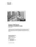
1
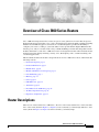
Introduction to Cisco 3800 Series Routers
Hardware Documentation
This introduction discusses the objectives, audience, and conventions of hardware documentation for
Cisco 3800 series integrated services routers, and describes related documents where you can find
additional information. It contains the following sections:
•
Objectives and Organization, page 1
•
Audience, page 2
•
Conventions, page 2
•
Safety Warnings, page 3
•
Related Documentation, page 9
•
Cisco 90-Day Limited Hardware Warranty Terms, page 10
•
Obtaining Documentation, page 11
•
Documentation Feedback, page 12
•
Obtaining Technical Assistance, page 12
•
Obtaining Additional Publications and Information, page 13
Objectives and Organization
This series of documents provides comprehensive hardware information for Cisco 3800 series integrated
services routers. It includes the following modules:
•
Overview of Cisco 3800 Series Routers
•
Preinstallation Requirements and Planning for Cisco 3800 Series Routers
•
Installing Cisco 3800 Series Routers in an Equipment Rack
•
Connecting Cables to Cisco 3800 Series Routers
•
Powering Up Cisco 3800 Series Routers
•
Troubleshooting Cisco 3800 Series Routers
•
Installing Network Modules in Cisco 3800 Series Routers
•
Installing Interface Cards in Cisco 3800 Series Routers
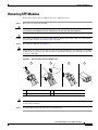
•
Installing SFP Modules in Cisco 3800 Series Routers
Introduction to Hardware Documentation
OL-5965-01
1
Audience
•
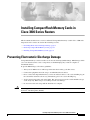
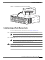
Installing CompactFlash Memory Cards in Cisco 3800 Series Routers
•
Installing and Upgrading Internal Components in Cisco 3800 Series Routers
For software configuration information, see the Cisco 3800 series software configuration documents and
the Cisco IOS configuration guides and command references. These publications are available online on
Cisco.com. See the “Obtaining Documentation” section on page 11 for more information.
For warranty, service, and support information, see the “Cisco 90-Day Limited Hardware Warranty
Terms” section on page 10.
These documents describe several router models that are similar in functionality, but differ in certain
respects. Some information may not apply to all router models.
Audience
These documents are intended for the person installing, configuring, and maintaining the router, who
should be familiar with electronic circuitry and wiring practices and have experience as an electronic or
electromechanical technician. Certain identified procedures should be performed only by trained and
qualified personnel.
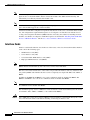
Conventions
These documents use the conventions listed in Table 1.
Table 1
Document Conventions
Convention
Description
boldface font
Commands and keywords.
italic font
Variables for which you supply values.
[
Optional keywords or arguments.
]
{x | y | z}
A choice of required keywords. You must select exactly one.
screen font
Information displayed on the screen.
boldface screen font
Information you must enter.
<
>
Nonprinting characters, such as passwords, appear in angle brackets in contexts where italics are
not available.
[
]
Default responses to system prompts.
Note
Timesaver
Means reader take note. Notes contain helpful suggestions or references to material not covered in the
manual.
Means the described action saves time. You can save time by performing the action described in the
paragraph.
Introduction to Hardware Documentation
2
OL-5965-01
Safety Warnings
Tip
Caution
Means the following information will help you solve a problem. The tips information might not be
troubleshooting or even an action, but could be useful information, similar to a Timesaver.
Means reader be careful. In this situation, you might do something that could result in equipment
damage or loss of data.
Safety Warnings
Safety warnings appear throughout these documents in procedures that, if performed incorrectly, may
harm you. A warning symbol precedes each warning statement. To see translations of the warnings that
appear in this publication, see the Cisco 3800 Series Routers Regulatory Compliance and Safety
Information document that accompanied your router.
Warning
IMPORTANT SAFETY INSTRUCTIONS
This warning symbol means danger. You are in a situation that could cause bodily injury. Before you
work on any equipment, be aware of the hazards involved with electrical circuitry and be familiar
with standard practices for preventing accidents. Use the statement number provided at the end of
each warning to locate its translation in the translated safety warnings that accompanied this
device. Statement 1071
SAVE THESE INSTRUCTIONS
Waarschuwing
BELANGRIJKE VEILIGHEIDSINSTRUCTIES
Dit waarschuwingssymbool betekent gevaar. U verkeert in een situatie die lichamelijk letsel kan
veroorzaken. Voordat u aan enige apparatuur gaat werken, dient u zich bewust te zijn van de bij
elektrische schakelingen betrokken risico's en dient u op de hoogte te zijn van de standaard
praktijken om ongelukken te voorkomen. Gebruik het nummer van de verklaring onderaan de
waarschuwing als u een vertaling van de waarschuwing die bij het apparaat wordt geleverd, wilt
raadplegen.
BEWAAR DEZE INSTRUCTIES
Varoitus
TÄRKEITÄ TURVALLISUUSOHJEITA
Tämä varoitusmerkki merkitsee vaaraa. Tilanne voi aiheuttaa ruumiillisia vammoja. Ennen kuin
käsittelet laitteistoa, huomioi sähköpiirien käsittelemiseen liittyvät riskit ja tutustu
onnettomuuksien yleisiin ehkäisytapoihin. Turvallisuusvaroitusten käännökset löytyvät laitteen
mukana toimitettujen käännettyjen turvallisuusvaroitusten joukosta varoitusten lopussa näkyvien
lausuntonumeroiden avulla.
SÄILYTÄ NÄMÄ OHJEET
Introduction to Hardware Documentation
OL-5965-01
3
Safety Warnings
Attention
IMPORTANTES INFORMATIONS DE SÉCURITÉ
Ce symbole d'avertissement indique un danger. Vous vous trouvez dans une situation pouvant
entraîner des blessures ou des dommages corporels. Avant de travailler sur un équipement, soyez
conscient des dangers liés aux circuits électriques et familiarisez-vous avec les procédures
couramment utilisées pour éviter les accidents. Pour prendre connaissance des traductions des
avertissements figurant dans les consignes de sécurité traduites qui accompagnent cet appareil,
référez-vous au numéro de l'instruction situé à la fin de chaque avertissement.
CONSERVEZ CES INFORMATIONS
Warnung
WICHTIGE SICHERHEITSHINWEISE
Dieses Warnsymbol bedeutet Gefahr. Sie befinden sich in einer Situation, die zu Verletzungen
führen kann. Machen Sie sich vor der Arbeit mit Geräten mit den Gefahren elektrischer Schaltungen
und den üblichen Verfahren zur Vorbeugung vor Unfällen vertraut. Suchen Sie mit der am Ende jeder
Warnung angegebenen Anweisungsnummer nach der jeweiligen Übersetzung in den übersetzten
Sicherheitshinweisen, die zusammen mit diesem Gerät ausgeliefert wurden.
BEWAHREN SIE DIESE HINWEISE GUT AUF.
Avvertenza
IMPORTANTI ISTRUZIONI SULLA SICUREZZA
Questo simbolo di avvertenza indica un pericolo. La situazione potrebbe causare infortuni alle
persone. Prima di intervenire su qualsiasi apparecchiatura, occorre essere al corrente dei pericoli
relativi ai circuiti elettrici e conoscere le procedure standard per la prevenzione di incidenti.
Utilizzare il numero di istruzione presente alla fine di ciascuna avvertenza per individuare le
traduzioni delle avvertenze riportate in questo documento.
CONSERVARE QUESTE ISTRUZIONI
Advarsel
VIKTIGE SIKKERHETSINSTRUKSJONER
Dette advarselssymbolet betyr fare. Du er i en situasjon som kan føre til skade på person. Før du
begynner å arbeide med noe av utstyret, må du være oppmerksom på farene forbundet med
elektriske kretser, og kjenne til standardprosedyrer for å forhindre ulykker. Bruk nummeret i slutten
av hver advarsel for å finne oversettelsen i de oversatte sikkerhetsadvarslene som fulgte med denne
enheten.
TA VARE PÅ DISSE INSTRUKSJONENE
Aviso
INSTRUÇÕES IMPORTANTES DE SEGURANÇA
Este símbolo de aviso significa perigo. Você está em uma situação que poderá ser causadora de
lesões corporais. Antes de iniciar a utilização de qualquer equipamento, tenha conhecimento dos
perigos envolvidos no manuseio de circuitos elétricos e familiarize-se com as práticas habituais de
prevenção de acidentes. Utilize o número da instrução fornecido ao final de cada aviso para
localizar sua tradução nos avisos de segurança traduzidos que acompanham este dispositivo.
GUARDE ESTAS INSTRUÇÕES
Introduction to Hardware Documentation
4
OL-5965-01
Safety Warnings
¡Advertencia!
INSTRUCCIONES IMPORTANTES DE SEGURIDAD
Este símbolo de aviso indica peligro. Existe riesgo para su integridad física. Antes de manipular
cualquier equipo, considere los riesgos de la corriente eléctrica y familiarícese con los
procedimientos estándar de prevención de accidentes. Al final de cada advertencia encontrará el
número que le ayudará a encontrar el texto traducido en el apartado de traducciones que acompaña
a este dispositivo.
GUARDE ESTAS INSTRUCCIONES
Varning!
VIKTIGA SÄKERHETSANVISNINGAR
Denna varningssignal signalerar fara. Du befinner dig i en situation som kan leda till personskada.
Innan du utför arbete på någon utrustning måste du vara medveten om farorna med elkretsar och
känna till vanliga förfaranden för att förebygga olyckor. Använd det nummer som finns i slutet av
varje varning för att hitta dess översättning i de översatta säkerhetsvarningar som medföljer denna
anordning.
SPARA DESSA ANVISNINGAR
Introduction to Hardware Documentation
OL-5965-01
5
Safety Warnings
Aviso
INSTRUÇÕES IMPORTANTES DE SEGURANÇA
Este símbolo de aviso significa perigo. Você se encontra em uma situação em que há risco de lesões
corporais. Antes de trabalhar com qualquer equipamento, esteja ciente dos riscos que envolvem os
circuitos elétricos e familiarize-se com as práticas padrão de prevenção de acidentes. Use o
número da declaração fornecido ao final de cada aviso para localizar sua tradução nos avisos de
segurança traduzidos que acompanham o dispositivo.
GUARDE ESTAS INSTRUÇÕES
Advarsel
VIGTIGE SIKKERHEDSANVISNINGER
Dette advarselssymbol betyder fare. Du befinder dig i en situation med risiko for
legemesbeskadigelse. Før du begynder arbejde på udstyr, skal du være opmærksom på de
involverede risici, der er ved elektriske kredsløb, og du skal sætte dig ind i standardprocedurer til
undgåelse af ulykker. Brug erklæringsnummeret efter hver advarsel for at finde oversættelsen i de
oversatte advarsler, der fulgte med denne enhed.
GEM DISSE ANVISNINGER
Introduction to Hardware Documentation
6
OL-5965-01
Safety Warnings
Introduction to Hardware Documentation
OL-5965-01
7
Safety Warnings
Introduction to Hardware Documentation
8
OL-5965-01
Related Documentation
Related Documentation
The Cisco IOS software that runs on your Cisco 3800 series router includes extensive features and
functionality. For information beyond the scope of these hardware documents, see the resources listed
in Table 2.
Timesaver
Make sure that you have access to the documents listed in Table 2. Some of these documents are
available in print, and all are on the World Wide Web at Cisco.com, http://www.cisco.com. If you need
to order printed documents, see the “Obtaining Documentation” section on page 11.
Table 2
Related and Referenced Documents
Cisco Product
Document
Cisco 3800 series routers
Cisco 3800 Series Integrated Services Routers Quick Start Guide
Cisco 3800 Series Software Configuration
Cisco 3800 Series Cards and Modules
Cisco 2800 Series and Cisco 3800 Series Integrated Services Routers
Regulatory Compliance and Safety Information
Quick Start Guide: Network Modules for Cisco Access Routers
Cisco Network Modules Hardware Installation Guide
Quick Start Guide: Interface Cards for Cisco Access Routers
Cisco Interface Cards Installation Guide
Cisco Modular Access Router Cable Specifications
Cisco RPS-675 Redundant Power System Hardware Installation Guide
Network management
system
Network management software documentation
Cisco IOS software
Cisco IOS software documentation, all releases
Refer to documentation for the Cisco IOS software release installed on
your router.
Introduction to Hardware Documentation
OL-5965-01
9
Cisco 90-Day Limited Hardware Warranty Terms
Cisco 90-Day Limited Hardware Warranty Terms
There are special terms applicable to your hardware warranty and various services that you can use
during the warranty period. Your formal Warranty Statement, including the warranties and license
agreements applicable to Cisco software, is available on Cisco.com. Follow these steps to access and
download the Cisco Information Packet and your warranty and license agreements from Cisco.com.
1.
Launch your browser, and go to this URL:
http://www.cisco.com/univercd/cc/td/doc/es_inpck/cetrans.htm
The Warranties and License Agreements page appears.
2.
To read the Cisco Information Packet, follow these steps:
a. Click the Information Packet Number field, and make sure that the part number
78-5235-03A0 is highlighted.
b. Select the language in which you would like to read the document.
c. Click Go.
The Cisco Limited Warranty and Software License page from the Information Packet appears.
d. Read the document online, or click the PDF icon to download and print the document in Adobe
Portable Document Format (PDF).
Note
3.
You must have Adobe Acrobat Reader to view and print PDF files. You can download
the reader from Adobe’s website: http://www.adobe.com
To read translated and localized warranty information about your product, follow these steps:
a. Enter this part number in the Warranty Document Number field:
78-5236-01C0
b. Select the language in which you would like to read the document.
c. Click Go.
The Cisco warranty page appears.
d. Review the document online, or click the PDF icon to download and print the document in
Adobe Portable Document Format (PDF).
You can also contact the Cisco service and support website for assistance:
http://www.cisco.com/public/Support_root.shtml.
Duration of Hardware Warranty
Ninety (90) days.
Replacement, Repair, or Refund Policy for Hardware
Cisco or its service center will use commercially reasonable efforts to ship a replacement part within ten
(10) working days after receipt of a Return Materials Authorization (RMA) request. Actual delivery
times can vary, depending on the customer location.
Cisco reserves the right to refund the purchase price as its exclusive warranty remedy.
Introduction to Hardware Documentation
10
OL-5965-01
Obtaining Documentation
To Receive a Return Materials Authorization (RMA) Number
Contact the company from whom you purchased the product. If you purchased the product directly from
Cisco, contact your Cisco Sales and Service Representative.
Complete the information below, and keep it for reference:
Company product purchased from
Company telephone number
Product model number
Product serial number
Maintenance contract number
Obtaining Documentation
Cisco documentation and additional literature are available on Cisco.com. Cisco also provides several
ways to obtain technical assistance and other technical resources. These sections explain how to obtain
technical information from Cisco Systems.
Cisco.com
You can access the most current Cisco documentation at this URL:
http://www.cisco.com/univercd/home/home.htm
You can access the Cisco website at this URL:
http://www.cisco.com
You can access international Cisco websites at this URL:
http://www.cisco.com/public/countries_languages.shtml
Ordering Documentation
You can find instructions for ordering documentation at this URL:
http://www.cisco.com/univercd/cc/td/doc/es_inpck/pdi.htm
You can order Cisco documentation in these ways:
•
Registered Cisco.com users (Cisco direct customers) can order Cisco product documentation from
the Ordering tool:
http://www.cisco.com/en/US/partner/ordering/index.shtml
•
Nonregistered Cisco.com users can order documentation through a local account representative by
calling Cisco Systems Corporate Headquarters (California, USA) at 408 526-7208 or, elsewhere in
North America, by calling 800 553-NETS (6387).
Introduction to Hardware Documentation
OL-5965-01
11
Documentation Feedback
Documentation Feedback
You can send comments about technical documentation to [email protected].
You can submit comments by using the response card (if present) behind the front cover of your
document or by writing to the following address:
Cisco Systems
Attn: Customer Document Ordering
170 West Tasman Drive
San Jose, CA 95134-9883
We appreciate your comments.
Obtaining Technical Assistance
For all customers, partners, resellers, and distributors who hold valid Cisco service contracts, Cisco
Technical Support provides 24-hour-a-day, award-winning technical assistance. The Cisco Technical
Support Website on Cisco.com features extensive online support resources. In addition, Cisco Technical
Assistance Center (TAC) engineers provide telephone support. If you do not hold a valid Cisco service
contract, contact your reseller.
Cisco Technical Support Website
The Cisco Technical Support Website provides online documents and tools for troubleshooting and
resolving technical issues with Cisco products and technologies. The website is available 24 hours a day,
365 days a year at this URL:
http://www.cisco.com/techsupport
Access to all tools on the Cisco Technical Support Website requires a Cisco.com user ID and password.
If you have a valid service contract but do not have a user ID or password, you can register at this URL:
http://tools.cisco.com/RPF/register/register.do
Submitting a Service Request
Using the online TAC Service Request Tool is the fastest way to open S3 and S4 service requests. (S3
and S4 service requests are those in which your network is minimally impaired or for which you require
product information.) After you describe your situation, the TAC Service Request Tool automatically
provides recommended solutions. If your issue is not resolved using the recommended resources, your
service request will be assigned to a Cisco TAC engineer. The TAC Service Request Tool is located at
this URL:
http://www.cisco.com/techsupport/servicerequest
For S1 or S2 service requests or if you do not have Internet access, contact the Cisco TAC by telephone.
(S1 or S2 service requests are those in which your production network is down or severely degraded.)
Cisco TAC engineers are assigned immediately to S1 and S2 service requests to help keep your business
operations running smoothly.
Introduction to Hardware Documentation
12
OL-5965-01
Obtaining Additional Publications and Information
To open a service request by telephone, use one of the following numbers:
Asia-Pacific: +61 2 8446 7411 (Australia: 1 800 805 227)
EMEA: +32 2 704 55 55
USA: 1 800 553 2447
For a complete list of Cisco TAC contacts, go to this URL:
http://www.cisco.com/techsupport/contacts
Definitions of Service Request Severity
To ensure that all service requests are reported in a standard format, Cisco has established severity
definitions.
Severity 1 (S1)—Your network is “down,” or there is a critical impact to your business operations. You
and Cisco will commit all necessary resources around the clock to resolve the situation.
Severity 2 (S2)—Operation of an existing network is severely degraded, or significant aspects of your
business operation are negatively affected by inadequate performance of Cisco products. You and Cisco
will commit full-time resources during normal business hours to resolve the situation.
Severity 3 (S3)—Operational performance of your network is impaired, but most business operations
remain functional. You and Cisco will commit resources during normal business hours to restore service
to satisfactory levels.
Severity 4 (S4)—You require information or assistance with Cisco product capabilities, installation, or
configuration. There is little or no effect on your business operations.
Obtaining Additional Publications and Information
Information about Cisco products, technologies, and network solutions is available from various online
and printed sources.
•
Cisco Marketplace provides a variety of Cisco books, reference guides, and logo merchandise. Visit
Cisco Marketplace, the company store, at this URL:
http://www.cisco.com/go/marketplace/
•
The Cisco Product Catalog describes the networking products offered by Cisco Systems, as well as
ordering and customer support services. Access the Cisco Product Catalog at this URL:
http://cisco.com/univercd/cc/td/doc/pcat/
•
Cisco Press publishes a wide range of general networking, training and certification titles. Both new
and experienced users will benefit from these publications. For current Cisco Press titles and other
information, go to Cisco Press at this URL:
http://www.ciscopress.com
•
Packet magazine is the Cisco Systems technical user magazine for maximizing Internet and
networking investments. Each quarter, Packet delivers coverage of the latest industry trends,
technology breakthroughs, and Cisco products and solutions, as well as network deployment and
troubleshooting tips, configuration examples, customer case studies, certification and training
information, and links to scores of in-depth online resources. You can access Packet magazine at
this URL:
http://www.cisco.com/packet
Introduction to Hardware Documentation
OL-5965-01
13
Obtaining Additional Publications and Information
•
iQ Magazine is the quarterly publication from Cisco Systems designed to help growing companies
learn how they can use technology to increase revenue, streamline their business, and expand
services. The publication identifies the challenges facing these companies and the technologies to
help solve them, using real-world case studies and business strategies to help readers make sound
technology investment decisions. You can access iQ Magazine at this URL:
http://www.cisco.com/go/iqmagazine
•
Internet Protocol Journal is a quarterly journal published by Cisco Systems for engineering
professionals involved in designing, developing, and operating public and private internets and
intranets. You can access the Internet Protocol Journal at this URL:
http://www.cisco.com/ipj
•
World-class networking training is available from Cisco. You can view current offerings at
this URL:
http://www.cisco.com/en/US/learning/index.html
CCVP, the Cisco Logo, and the Cisco Square Bridge logo are trademarks of Cisco Systems, Inc.; Changing the Way We Work, Live, Play, and Learn is a
service mark of Cisco Systems, Inc.; and Access Registrar, Aironet, BPX, Catalyst, CCDA, CCDP, CCIE, CCIP, CCNA, CCNP, CCSP, Cisco, the Cisco
Certified Internetwork Expert logo, Cisco IOS, Cisco Press, Cisco Systems, Cisco Systems Capital, the Cisco Systems logo, Cisco Unity,
Enterprise/Solver, EtherChannel, EtherFast, EtherSwitch, Fast Step, Follow Me Browsing, FormShare, GigaDrive, GigaStack, HomeLink, Internet
Quotient, IOS, iPhone, IP/TV, iQ Expertise, the iQ logo, iQ Net Readiness Scorecard, iQuick Study, LightStream, Linksys, MeetingPlace, MGX,
Networking Academy, Network Registrar, Packet, PIX, ProConnect, RateMUX, ScriptShare, SlideCast, SMARTnet, StackWise, The Fastest Way to
Increase Your Internet Quotient, and TransPath are registered trademarks of Cisco Systems, Inc. and/or its affiliates in the United States and certain other
countries.
All other trademarks mentioned in this document or Website are the property of their respective owners. The use of the word partner does not imply a
partnership relationship between Cisco and any other company. (0612R)
Copyright © 2004 Cisco Systems, Inc. All rights reserved.
Introduction to Hardware Documentation
14
OL-5965-01
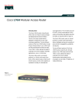
Overview of Cisco 3800 Series Routers
Cisco 3800 series integrated services routers are part of a new generation of routers that incorporate
high-performance integrated data, voice, video, and virtual private network (VPN) capability, including
hardware-based VPN encryption acceleration, in a modular design that provides the flexibility to
configure your router according to your needs. These routers provide built-in Gigabit Ethernet LAN
interface ports, and you can add a wide variety of LAN and WAN ports with interchangeable network
modules and interface cards. Cisco 3800 series routers are designed for branch office installations that
need integrated low-density switching, security, voice, IP telephony, video, content networking, and
concurrent applications.
This document describes the features and specifications of Cisco 3800 series routers, and includes the
following sections:
•
Router Descriptions, page 1
•
Product Identification, page 5
•
Built-In Ports, page 6
•
Module and Interface Card Capacity, page 7
•
Port Numbering, page 9
•
Memory, page 11
•
Power, page 11
•
LED Indicators, page 12
•
Ventilation, page 12
•
Real-Time Clock and Battery, page 12
•
Technical Specifications, page 12
•
Regulatory Compliance, page 15
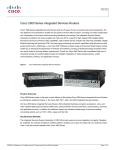
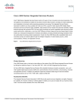
Router Descriptions
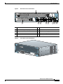
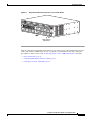
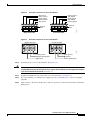
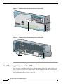
There are two routers in the Cisco 3800 series—the Cisco 3825 router and the Cisco 3845 router. The
Cisco 3825 router (shown in Figure 1 to Figure 4) is two rack units (3.5 inches) high. The Cisco 3845
router (shown in Figure 5 to Figure 8) is three rack units (5.25 inches) high.
Overview of Cisco 3800 Series Routers
OL-5966-01
1
Router Descriptions
Figure 1
Front View of Cisco 3825 Router
R
1
FLASH
0
Figure 2
SYS
AUX
ACT
RPS
IP PWR
AIM0
AIM1
117040
COMPACT
PVDM0
PVDM1
PVDM2
PVDM3
Front Panel of Cisco 3825 Router
2
1
3
4
5
6
100-240 V~ 3A
50/60 Hz
1
0
SYS
ACT
SYS
PWR
RPS
AUX
PWR
AIM0
AIM1
PVDM0 PVDM1 PVDM2 PVDM3
116841
COMPACT FLASH
CF
DO NOT REMOVE DURING NETWORK OPERATION
1
Cisco Redundant Power System (RPS) connector
4
LED indicators
2
CompactFlash memory card slot
5
Power switch
3
USB ports
6
Power connector (AC shown)
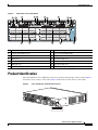
Figure 3
NMDESW36
Rear View of Cisco 3825 Router
35x
GE1
FastEthe
rnet Ports
10/100/100
Base-Tx 0
17x
35x 17x
34x 16x
33x 15x
15x
32x 14x
31x 13x
FastEthern
et Ports
30x 12x
29x 11x
18x
28x 10x
27x 9x
26x
8x
8x
7x
Ext
Pwr
15x 7x
-48V
14x
6x
13x
5x
12x
4x
11x 3x
10x 2x
9x
0x
1x
8x
GE
10/100/
1000
Base-Tx
EN
0x
Ext
Pwr
25x
17
24x
-48V
6x
23x
5x
22x
4x
21x 3x
20x
2x
19x
0x
1x
18x
0x
GE0
10/100/
1000
Base-Tx
EN
122285
NMESW16
Overview of Cisco 3800 Series Routers
2
OL-5966-01
Router Descriptions
Figure 4
Rear Panel of Cisco 3825 Router
1
NMDESW36
2
FastEthernet Ports
35x
18x
Ext
Pwr
GE1
-48V
GE0
10/100/
1000
Base-Tx
EN
10/100/1000 17x
Base-Tx
0x
35x 17x
NMESW16
34x 16x
33x 15x
32x 14x
31x 13x
30x 12x
29x 11x
28x 10x
27x 9x
-48V
GE
10/100/
1000
Base-Tx
26x
8x
25x
24x
6x
23x
5x
22x
4x
21x 3x
20x
2x
19x
1x
18x
0x
CONSOLE
FastEthernet Ports
15x
8x
Ext
Pwr
EN
7x
1
17
0x
15x 7x
14x
6x
13x
5x
12x
4x
11x 3x
10x
2x
9x
1x
8x
0x
H
W
I
C
H
W
I
C
3
2
H
W
I
C
H
W
I
C
1
0
3
4
5
6
7
1
Network module slot 2
6
HWIC slot 2
2
Screw holes for grounding lug
7
HWIC slot 0
3
Network module slot 1
8
Console and auxiliary ports
4
HWIC slot 3
9
Gigabit Ethernet ports
5
HWIC slot 1
10 Slot for optional SFP module
GE 0/1
LNK
Cisco 3825
AUX
8
SPD
GE 0/0
9
LNK
SFP
10
Front View of Cisco 3845 Router
117045
Figure 5
SPD
116842
2
Overview of Cisco 3800 Series Routers
OL-5966-01
3
Router Descriptions
Figure 6
Front Panel of Cisco 3845 Router
2
3
4
1
LED indicators
3
Power connector (AC shown)
2
Power switch
4
Location of optional second power supply
Rear View of Cisco 3845 Router
117774
Figure 7
116843
1
Overview of Cisco 3800 Series Routers
4
OL-5966-01
Product Identification
Figure 8
Rear Panel of Cisco 3845 Router
1
3
2
15
4
5
7
6
8
GE 0/1
CONSOLE
1
0
9
HWIC 3
PVDM 3 PVDM 2
HWIC 1
HWIC 2
AUX
PVDM 1 PVDM 0
AIM 1
AIM 0
SPD
LNK
SPD
LNK
HWIC 0
SFP
CF
Do Not Remove During Network Operation
GE 0/0
3
CISCO3845
4
116844
1
2
10
11
12
14
13
1
USB ports
8
Gigabit Ethernet ports
2
Console and auxiliary ports
9
Slot for optional SFP module
3
HWIC slot 3
10 Network module slot 4
4
HWIC slot 2
11 Network module slot 2
5
HWIC slot 1
12 Network module slot 3
6
LED indicators
13 Network module slot 1
7
HWIC slot 0
14 Screw holes for grounding lug
Product Identification
The serial number for Cisco 3800 series routers is located near the right edge of the rear panel. Figure 9
shows the location on Cisco 3825 routers. Figure 10 shows the location on Cisco 3845 routers.
NMDESW36
Cisco 3825 Router Serial Number Location
121294 781-00282-01 C0
Figure 9
35x
GE1
FastEthe
rnet Ports
10/100/100
Base-Tx 0
17x
NMESW16
35x 17x
34x 16x
33x 15x
15x
32x 14x
31x 13x
FastEthern
et Ports
30x 12x
29x 11x
18x
28x 10x
27x 9x
8x
7x
Ext
Pwr
15x 7x
-48V
14x 6x
13x
5x
12x
4x
11x 3x
10x 2x
9x
0x
1x
8x
GE
10/100/
1000
Base-Tx
26x
8x
Ext
Pwr
25x
17
24x
-48V
6x
23x
5x
22x
4x
21x 3x
20x
2x
19x
0x
1x
18x
GE0
10/100/
1000
Base-Tx
EN
0x
EN
0x
SN: XXXN
NNNXXXX
SN: XXXNNNNXXXX
Overview of Cisco 3800 Series Routers
OL-5966-01
5
Built-In Ports
NMESW16
Cisco 3845 Router Serial Number Location
121293, 781-00283-01 B0
Figure 10
15x
FastEthe
rnet Port
s
8x
7x
15x 7x
Ext
Pwr
14x
-48V
6x
13x
GE
5x
12x
4x
11x 3x
10x
2x
9x
0x
1x
8x
10/10
1000 0/
Base-Tx
EN
0x
SN: XXXNNNNXXXX
SN: XXXNNNNXXXX
Note
The serial number for Cisco 3825 and Cisco 3845 routers is 11 characters long.
Cisco Product Identification Tool
The Cisco Product Identification tool provides detailed illustrations and descriptions showing where to
locate serial number labels on Cisco products. It includes the following features:
•
A search option that allows browsing for models using a tree-structured product hierarchy
•
A search field on the final results page making it easier to look up multiple products
•
End-of-sale products are clearly identified in results lists
The tool streamlines the process of locating serial number labels and identifying products. Serial number
information expedites the entitlement process and is important for access to support services.
The Cisco Product Identification tool can be accessed at the following URL:
http://tools.cisco.com/Support/CPI/index.do
Built-In Ports
Cisco 3800 series routers provide the following built-in ports:
•
Two 1000BASE-T Gigabit Ethernet ports with RJ-45 connectors for shielded twisted pair. One of
these ports provides a slot for an optional small-form-factor pluggable (SFP) module.
•
One RJ-45 console port for connecting to a terminal.
•
One RJ-45 auxiliary port for connecting to a modem.
•
Two built-in USB 1.1 ports to support USB devices qualified and approved by Cisco. No approved
USB devices are currently available, but enhancements are planned to provide additional flexibility
and functionality.
•
Cisco Redundant Power System connector (Cisco 3825 router only).
Overview of Cisco 3800 Series Routers
6
OL-5966-01
Module and Interface Card Capacity
Module and Interface Card Capacity
Optional network modules and interface cards provide Cisco 3800 series routers with additional
interfaces or functionality.
Network Modules
Network modules install directly into slots in the rear of the router. The Cisco 3845 router supports
online insertion and removal (OIR, or hot swap) of network modules. The Cisco 3825 router does not
support OIR.
Caution
The Cisco 3845 router supports OIR with similar modules only. If you remove a network module, along
with any installed WAN or voice interface cards, install another module and card combination exactly
like it.
Caution
The Cisco 3825 router does not support OIR of network modules. To avoid damaging the module, you
must turn off electrical power and disconnect network cables before you insert the module into a router
slot.
The Cisco 3825 router provides two slots for network modules. The lower network module slot of this
router, labeled 1 on the rear panel, can hold either of the following sizes of network modules:
•
One single-wide network module
•
One extended single-wide network module
The upper network module slot of the Cisco 3825 router, labeled 2 on the rear panel, can hold any of the
following sizes of network modules:
•
One single-wide network module
•
One extended single-wide network module
•
One double-wide network module
•
One extended double-wide network module
The Cisco 3845 router provides four slots for network modules, labeled 1, 2, 3, and 4 on the rear panel.
Each slot can hold either of the following sizes of network modules:
•
One single-wide network module
•
One extended single-wide network module
Slots 1 and 2 can also be combined to hold either of the following sizes of network modules:
•
One double-wide network module
•
One extended double-wide network module
Slots 3 and 4 can be combined in the same way to hold one double-wide or extended double-wide
network module.
Overview of Cisco 3800 Series Routers
OL-5966-01
7
Module and Interface Card Capacity
Note
The terms single-wide, extended single-wide, double-wide, and extended double-wide refer to the
physical size of a network module. Enhanced network modules offer additional functionality; this
functionality is not directly related to the module’s size.
Note
The Cisco 3825 router supports one high-density analog-digital extension module for voice and fax. The
Cisco 3845 module supports two of these modules.
Certain network module configurations require the installation or removal of a slot divider in the module
slot. All configurations require blank faceplates or slot adapters to be installed over unused slots for
cooling, electromagnetic interference (EMI) reduction, and safety. Procedures for installing network
modules, slot dividers, slot adapters, and blank faceplates are described in “Installing Network Modules
in Cisco 3800 Series Routers” and the Cisco Network Modules Hardware Installation Guide.
Interface Cards
Interface cards install either into slots in the rear of the router, or into slots in network modules. Interface
cards come in the following types:
Note
•
WAN interface card (WIC)
•
Voice interface card (VIC)
•
Voice/data T1/E1 WAN interface card (VWIC)
•
High-speed WAN interface card (HWIC)
You can insert any kind of interface card—WIC, VIC, VWIC, or HWIC—into a router HWIC slot.
HWICs must be installed directly into router slots, not into network modules.
The Cisco 3825 router and the Cisco 3845 router each provide four interface card slots, labeled on the
rear panel by HWIC and a number. Each slot can be occupied by one single-wide WIC, VIC, VWIC, or
HWIC.
In addition, the HWIC 0 and HWIC 1 slots can be combined to hold one double-wide HWIC. The
HWIC 2 and HWIC 3 slots can also be combined to hold one double-wide HWIC.
Note
Although the HWIC 1 and HWIC 2 slots on the Cisco 3845 router are adjacent to each other, they cannot
be combined to hold a double-wide HWIC.
The maximum capacity of Cisco 3800 series routers for interface cards inserted directly into the chassis
is four WICs, VICs, VWICs, or HWICs, or two double-wide HWICs.
Caution
Cisco 3800 series routers do not support OIR (hot swap) of interface cards inserted directly into router
slots. You must turn off the router before installing or removing an interface card.
Overview of Cisco 3800 Series Routers
8
OL-5966-01
Port Numbering
Certain interface card configurations require the installation or removal of a slot divider in the router’s
interface card slot. All slots must be covered by interface cards or blank faceplates for cooling,
electromagnetic interference (EMI) reduction, and safety. Procedures for installing interface cards, slot
dividers, and blank faceplates are described in “Installing Interface Cards in Cisco 3800 Series Routers”
and the Cisco Interface Cards Installation Guide.
AIMS and PVDMs
Advanced integration modules (AIMs) and packet voice data modules (PVDMs) install into connectors
on the router motherboard. AIMs provide hardware-based support for additional features. PVDMs are
digital signal processor (DSP) SIMMs that provide voice support. The Cisco 3825 router and the
Cisco 3845 router can each accommodate two AIMs and four PVDMs.
Installation, replacement, and removal of AIMs and PVDMs require opening the cover of the Cisco 3825
router, or removing the motherboard of the Cisco 3845 router. For more information, see “Installing and
Upgrading Internal Components in Cisco 3800 Series Routers.”
Port Numbering
Each built-in network port on a Cisco 3800 series router, and each port or interface on a network module
or interface card, is identified in Cisco IOS software by an interface type and a number or series of
numbers separated by forward slashes (/). Port numbers for Cisco 3800 series routers follow the rules in
this section.
Note
Port numbering conventions differ for different router series. For routers that are not part of the
Cisco 3800 series, consult your router documentation for port numbering information.
Built-In Ports
Cisco 3800 series routers have two Gigabit Ethernet ports built into the router’s rear panel, labeled 0/0
and 0/1. These numbers are used with the interface-type keyword gigabitethernet to identify the ports
in Cisco IOS commands—gigabitethernet 0/0 and gigabitethernet 0/1.
Note
If an optional SFP module is installed and selected, it is assigned gigabitethernet 0/0.
Network Module Ports
Ports on network modules inserted into a router slot are numbered slot/port, where slot is the slot number
in the router and port is the port number in the network module. For example, port 1 of a Fast Ethernet
network module inserted into router slot 2 would be identified as fastethernet 2/1.
The Cisco 3825 router has two slots for network modules. The lower slot is numbered 1 and the upper
slot is numbered 2, as labeled on the router’s rear panel. (See Figure 4 on page 3.) The Cisco 3845 router
has four slots: 1 at lower right, 2 at lower left, 3 at upper right, and 4 at upper left. (See Figure 8 on
page 5.)
Overview of Cisco 3800 Series Routers
OL-5966-01
9
Port Numbering
Note
In the Cisco 3845 router, double-wide or extended double-wide network modules are identified by slot
numbers 1 and 3.
Ports in a network module are normally numbered from right to left and bottom to top, starting at 0. See
the Cisco Network Modules Hardware Installation Guide for more information.
Interface Card Ports
Interface cards can be inserted either directly into a router slot, or into a slot in a network module.
Interface Card in Router
Interface cards inserted directly into a router slot are numbered 0/HWIC-slot/port. HWIC-slot is the
HWIC slot in the router—0, 1, 2, or 3, as labeled on the router’s rear panel; port is the port number in
the interface card. For example, port 0 of a T1 WIC inserted into router HWIC slot 3 would be identified
as t1 0/3/1.
Note
Double-wide interface cards use HWIC slot numbers 1 and 3.
Ports in an interface card are normally numbered from right to left and bottom to top, starting at 0. See
the Cisco Interface Cards Installation Guide for more information.
Interface Card in Network Module
Some network modules provide their own slots for interface cards. Ports in these interface cards are
numbered router-slot/module-slot/port, where router-slot is 1 or 2 for the Cisco 3825 router and 1, 2, 3,
or 4 for the Cisco 3845 router; module-slot is the slot in the network module for the interface card; and
port is the port number in the interface card. For example, port 0 of a voice interface card in slot 1 of a
voice network module in slot 4 of a Cisco 3845 router would be identified as voice 4/1/0.
Note
Double-wide or extended double-wide network modules use router slot numbers 2 and 4.
Slots in network modules for interface cards are normally numbered from right to left, starting at 0. Ports
in an interface card are normally numbered from right to left and bottom to top, starting at 0. For more
information, see the Cisco Network Modules Hardware Installation Guide and Cisco Interface Cards
Installation Guide.
Asynchronous Interface Numbering
For Cisco 3825 and Cisco 3845 routers, interface numbering for asynchronous interfaces is the same as for
other interfaces. Use the interface number to specify the asynchronous line. For example, the command
to configure port 1 of a 2-port asynchronous/synchronous WAN interface card in router HWIC slot 3 is
interface serial 0/3/1. The command to configure the line associated with this port is line 0/3/1.
Similarly, line 1/22 specifies the line associated with interface async 1/22 on a 32-port asynchronous
network module in router slot 1.
Overview of Cisco 3800 Series Routers
10
OL-5966-01
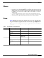
Memory
Memory
Cisco 3800 series routers contain the following types of memory:
•
Main memory consists of ECC DDR SDRAM. It stores the running configuration and routing tables,
and buffers packets at the network interfaces. Both routers ship with 256 MB of main memory. The
two DIMM slots can be upgraded with 128-MB, 256-MB, or 512-MB DIMMs to a maximum of
1024 MB (1 GB).
•
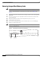
An external CompactFlash memory card stores the Cisco IOS software image. The routers are
shipped with a 64-MB CompactFlash memory card, which can be upgraded to 128 MB or 256 MB.
•
The routers boot from 4 MB of internal flash memory. This memory cannot be upgraded.
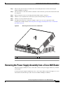
Power
Table 1 summarizes power options for Cisco 3800 series routers. Both the Cisco 3825 router and the
Cisco 3845 router support an AC input power supply, an AC input power supply with IP phone power
output, or a DC input power supply. The Cisco 3825 router has one internal power supply and also
provides a connector for the optional Cisco Redundant Power System (RPS) external backup power
source. The Cisco 3845 router supports two internal power supplies and operates in redundant mode both
are installed.
Table 1
Router
Cisco 3825
Cisco 3845
Cisco 3800 Series Routers Power Options
Power Option
Input
IP Phone Power Output
AC input without IP phone power
output
100–240 VAC, 3 A
None
AC input with 24 ports of IP phone
power output
100–240 VAC, 8 A
–48 VDC, 360 W
DC input without IP phone power
output
24–60 VDC, 12 A
None
Cisco Redundant Power System
100 VAC, 10 A
240 VAC, 6 A
If supported by router power supply
AC input without IP phone power
output
100–240 VAC, 5 A
None
AC input with 48 ports of IP phone
power output
100–240 VAC, 9 A
–48 VDC, 360 W
DC input without IP phone power
output
24–60 VDC, 19 A
None
Second internal power supply
Any option above
Overview of Cisco 3800 Series Routers
OL-5966-01
11
LED Indicators
LED Indicators
LEDs can help you monitor your router’s performance and operation by providing power, activity, and
status information. For an explanation of LED activity during power-up, see the “Verifying LED
Indications” section on page 34 of “Powering Up Cisco 3800 Series Routers.” To use LEDs for
troubleshooting, see Table 1 in “Troubleshooting Cisco 3800 Series Routers.”
For descriptions of LEDs on network modules or interface cards, see the Cisco Network Modules
Hardware Installation Guide and the Cisco Interface Cards Installation Guide.
Ventilation
Three internal multispeed fans cool the routers, controlled by a temperature sensor. At ambient
temperatures below 40 degrees C, they operate at low speed to conserve power and reduce noise. At
40 degrees C or above they operate at high speed. The power supply has its own integrated fan.
Note
On the Cisco 3825 router, when the router is installed with a Inline Power (ILP) power supply, the
internal multispeed fans will operate at high speed only. To verify the fan speed, use the show
environment command.
Real-Time Clock and Battery
An internal real-time clock (RTC) with battery backup allows the routers to check the validity of the
certification authority (CA) certificate. The RTC is accurate under the operating environmental
conditions specified for the router.
The clock and battery are permanently installed. Under the specified operating environmental
conditions, the battery lasts the life of the router and does not need to be replaced.
Technical Specifications
Table 2 and Table 3 list Cisco 3800 series system specifications.
Table 2
Cisco 3825 Router Specifications
Specification
Value
Dimensions (H x W x D)
3.5 x 17.1 x 14.7 in. (8.9 x 43.4 x 37.3 cm)
2 rack unit height
Weight (minimum)
23 lb (10.5 kg)
Overview of Cisco 3800 Series Routers
12
OL-5966-01
Technical Specifications
Table 2
Cisco 3825 Router Specifications (continued)
Specification
Value
AC input power
•
Input voltage
100–240 VAC, autoranging
•
Frequency
47–63 Hz
•
Input current
3 A (8 A for IP phone support) at 110 V
2 A (4 A for IP phone support) at 230 V
•
Inrush surge current
50 A maximum, one cycle
(–48V IP phone power included)
DC input power
•
Input voltage
24–60 VDC, positive or negative, autoranging
•
Input current
12 A at 24 V; 5 A at 60 V
•
Inrush surge current
50 A maximum, <10 ms
Power dissipation
(maximum)
•
AC without
IP phone support
•
AC with
IP phone support:
•
300 W (1025 BTU/hr)
– System only
370 W (1260 BTU/hr)
– IP phones
360 W (1230 BTU/hr)
DC
325 W (1110 BTU/hr)
Console and auxiliary ports
RJ-45 connector
Operating temperature
32 to 104°F (0 to 40°C)
Nonoperating temperature
–40 to 185°F (–40 to 85°C)
Operating humidity
5–95%, noncondensing
Operating altitude
Up to 6,500 ft (2,000 m); derate temperature 1°C per
1,000 ft
Noise level
50 dBA typical, 53 dBA maximum
Regulatory compliance
FCC Part 15 Class A. For additional compliance
information, see the Cisco 2800 Series and Cisco 3800
Series Integrated Services Routers Regulatory
Compliance and Safety Information document that
accompanied the router.
Safety compliance
UL 60950; CAN/CSA C22.2 No. 60950-00;
EN 60950; AS/NZS 3260
Overview of Cisco 3800 Series Routers
OL-5966-01
13
Technical Specifications
Table 3
Cisco 3845 Router Specifications
Specification
Value
Dimensions (H x W x D)
5.25 x 17.25 x 16.0 in. (13.3 x 43.8 x 40.6 cm)
3 rack unit height
Weight (minimum)
45 lb (20 kg)
AC input power
•
Input voltage
100–240 VAC, autoranging
•
Frequency
47–63 Hz
•
Input current
4 A (8 A for IP phone support) at 110 V
2 A (4 A for IP phone support) at 230 V
•
Inrush surge current
50 A maximum, one cycle (–48V IP phone power
included)
DC input power
•
Input voltage
24–60 VDC, positive or negative, autoranging
•
Input current
18 A at 24 V; 7 A at 60 V
•
Inrush surge current
50 A maximum, <10 ms
Power dissipation
(maximum)
•
AC without
IP phone support
•
AC with
IP phone support:
•
435 W (1485 BTU/hr)
– System only
555 W (1890 BTU/hr)
– IP phones
360 W (1230 BTU/hr)
DC
460 W (1570 BTU/hr)
Console and auxiliary ports
RJ-45 connector
Operating temperature
32 to 104°F (0 to 40°C)
Nonoperating temperature
-40 to 185°F (-40 to 85°C)
Operating humidity
5–95%, noncondensing
Operating altitude
Up to 6,500 ft (2,000 m); derate 1°C per 1,000 ft
Noise level
56 dBA typical, 58 dBA maximum
EMC compliance
FCC Part 15 Class A. For additional compliance
information, see the Cisco 2800 Series and Cisco 3800
Series Integrated Services Routers Regulatory
Compliance and Safety Information document.
Safety compliance
UL 60950; CAN/CSA C22.2 No. 60950-00;
EN 60950; AS/NZS 3260. For additional compliance
information, see the Cisco 2800 Series and Cisco 3800
Series Integrated Services Routers Regulatory
Compliance and Safety Information document.
Overview of Cisco 3800 Series Routers
14
OL-5966-01
Regulatory Compliance
Regulatory Compliance
For complete regulatory compliance information, see the Cisco 2800 Series and Cisco 3800 Series
Integrated Services Routers Regulatory Compliance and Safety Information document that accompanied
the router.
Overview of Cisco 3800 Series Routers
OL-5966-01
15
Regulatory Compliance
Overview of Cisco 3800 Series Routers
16
OL-5966-01
Preinstallation Requirements and Planning for
Cisco 3800 Series Routers
This document describes preinstallation requirements and planning for Cisco 3800 series integrated
services routers. It contains the following sections:
•
Safety Recommendations, page 1
•
General Site Requirements, page 3
•
Installation Checklist, page 6
•
Creating a Site Log, page 7
•
Inspecting the Router, page 7
•
Required Tools and Equipment for Installation and Maintenance, page 8
Safety Recommendations
Follow these guidelines to ensure general safety:
•
Keep the router area clear and dust-free during and after installation.
•
If you remove the router cover, put it in a safe place.
•
Keep tools and components away from walk areas.
•
Do not wear loose clothing that could get caught in the router. Fasten your tie or scarf and roll up
your sleeves.
•
Wear safety glasses when working under conditions that might be hazardous to your eyes.
•
Do not perform any action that creates a hazard to people or makes the equipment unsafe.
Warning
Read the installation instructions before connecting the system to the power source. Statement 1004
Warning
This unit is intended for installation in restricted access areas. A restricted access area can be
accessed only through the use of a special tool, lock and key, or other means of security.
Statement 1017
Preinstallation Requirements and Planning for Cisco 3800 Series Routers
OL-5967-01
1
Safety Recommendations
Warning
Blank faceplates and cover panels serve three important functions: they prevent exposure to
hazardous voltages and currents inside the chassis; they contain electromagnetic interference (EMI)
that might disrupt other equipment; and they direct the flow of cooling air through the chassis. Do not
operate the system unless all cards, faceplates, front covers, and rear covers are in place. Statement
1029
Warning
Only trained and qualified personnel should be allowed to install, replace, or service this equipment.
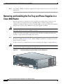
Statement 1030
Warning
To prevent personal injury or damage to the chassis, never attempt to lift or tilt the chassis using the
handles on modules (such as power supplies, fans, or cards); these types of handles are not designed
to support the weight of the unit. Statement 1032
Warning
This equipment must be installed and maintained by service personnel as defined by AS/NZS 3260.
Incorrectly connecting this equipment to a general-purpose outlet could be hazardous. The
telecommunications lines must be disconnected 1) before unplugging the main power connector or 2)
while the housing is open, or both. Statement 1043
Warning
Ultimate disposal of this product should be handled according to all national laws and regulations.
Statement 1040
Warning
To prevent the system from overheating, do not operate it in an area that exceeds the maximum
recommended ambient temperature of 40 deg. C Statement 1047
Safety with Electricity
Follow these guidelines when working on equipment powered by electricity:
Warning
Read the installation instructions before connecting the system to the power source. Statement 1004
•
Locate the emergency power-off switch in the room in which you are working. Then, if an electrical
accident occurs, you can quickly turn off the power.
•
Disconnect all power before doing the following:
– Installing or removing a router
– Working near power supplies
•
Look carefully for possible hazards in your work area, such as moist floors, ungrounded power
extension cables, frayed power cords, and missing safety grounds.
•
Do not work alone if hazardous conditions exist.
•
Never assume that power is disconnected from a circuit. Always check.
Preinstallation Requirements and Planning for Cisco 3800 Series Routers
2
OL-5967-01
General Site Requirements
•
If an electrical accident occurs, proceed as follows:
– Use caution; do not become a victim yourself.
– Turn off power to the device.
– If possible, send another person to get medical aid. Otherwise, assess the victim’s condition and
then call for help.
– Determine if the person needs rescue breathing or external cardiac compressions; then take
appropriate action.
In addition, use the following guidelines when working with any equipment that is disconnected from a
power source, but still connected to telephone wiring or other network cabling:
•
Never install telephone wiring during a lightning storm.
•
Never install telephone jacks in wet locations unless the jack is specifically designed for it.
•
Never touch uninsulated telephone wires or terminals unless the telephone line is disconnected at
the network interface.
•
Use caution when installing or modifying telephone lines.
Preventing Electrostatic Discharge Damage
Electrostatic discharge (ESD) can damage equipment and impair electrical circuitry. It can occur if
electronic printed circuit cards are improperly handled and can cause complete or intermittent failures.
Always follow ESD prevention procedures when removing and replacing modules:
Caution
•
Ensure that the router is electrically connected to earth ground.
•
Wear an ESD-preventive wrist strap, ensuring that it makes good skin contact. Connect the clip to
an unpainted surface of the router frame to channel unwanted ESD voltages safely to ground. To
guard against ESD damage and shocks, the wrist strap and cord must operate effectively.
•
If no wrist strap is available, ground yourself by touching a metal part of the router.
For the safety of your equipment, periodically check the resistance value of the antistatic strap. It should
be between 1 and 10 megohms (Mohm).
General Site Requirements
This section describes the requirements your site must meet for safe installation and operation of your
router. Ensure that the site is properly prepared before beginning installation. If you are experiencing
shutdowns or unusually high errors with your existing equipment, this section can also help you isolate
the cause of failures and prevent future problems.
Power Supply Considerations
Check the power at your site to ensure that you are receiving clean power (free of spikes and noise).
Install a power conditioner if necessary.
Preinstallation Requirements and Planning for Cisco 3800 Series Routers
OL-5967-01
3
General Site Requirements
Warning
The device is designed for connection to TN and IT power systems. Statement 1007
The AC power supply autoselects either 110 V or 220 V operation. All routers include a 6-foot
(1.8-meter) electrical power cord. A label near the power inlet indicates the correct voltage, frequency
(AC-powered systems only), and current draw for the router.
Table 1 lists power requirements for Cisco 3800 series routers.
Table 1
Power Requirements for Cisco 3800 Series Routers
Router
Power Supply
Input Power
Input Voltage
Tolerance Limits
Cisco 3825
without IP
phone power
output
AC
100 to 240 VAC
3 A at 110 V; 2 A at 230 V
47 to 63 Hz
85–264 VAC
DC
24 to 60 VDC, positive or negative, autoranging 18–72 VDC
12 A at 24 V; 5 A at 60 V
Cisco 3825
with IP phone
power output
AC
100 to 240 VAC
8 A at 110 V; 4 A at 230 V
47 to 63 Hz
85–264 VAC
Cisco 3845
without IP
phone power
output
AC
100 to 240 VAC
4 A at 110 V; 2 A at 230 V
47 to 63 Hz
85–264 VAC
DC
24 to 60 VDC, positive or negative, autoranging 18–72 VDC
19 A at 24 V; 8 A at 60 V
Cisco 3845
with IP phone
power output
AC
100 to 240 VAC
9 A at 110 V; 4 A at 230 V
47 to 63 Hz
85–264 VAC
Site Environment
Cisco 3800 series routers should normally be installed in an equipment rack. (For instructions, see
“Installing Cisco 3800 Series Routers in an Equipment Rack.”) The location of your router and the
layout of your equipment rack or wiring room are extremely important considerations for proper
operation. Equipment placed too close together, inadequate ventilation, and inaccessible panels can
cause malfunctions and shutdowns, and can make maintenance difficult. Plan for access to both front
and rear panels of the router.
Cisco 3800 series routers operate at a temperature of 32 to 104 degrees F (0 to 40 degrees C) and a
humidity of 5 to 95 percent (noncondensing).
When planning your site layout and equipment locations, remember the precautions described in the next
section, “Site Configuration,” to help avoid equipment failures and reduce the likelihood of
environmentally caused shutdowns. If you are experiencing shutdowns or an unusually high number of
errors with your existing equipment, these precautions may help you isolate the cause of the failures and
prevent future problems.
Preinstallation Requirements and Planning for Cisco 3800 Series Routers
4
OL-5967-01
General Site Requirements
Site Configuration
The following precautions help you plan the operating environment for your router and help avoid
environmentally caused equipment failures:
•
Ensure that the room where your router operates has adequate circulation. Electrical equipment
generates heat. Without adequate circulation, ambient air temperature may not cool equipment to
acceptable operating temperatures.
•
Always follow ESD-prevention procedures described in the “Preventing Electrostatic Discharge
Damage” section on page 3 to avoid damage to equipment. Damage from static discharge can cause
immediate or intermittent equipment failure.
•
Ensure that the router cover or motherboard tray and module rear panels are secure. All empty
network module slots, interface card slots, and power supply bays must have filler panels installed.
The router is designed to allow cooling air to flow within it through specially designed cooling slots.
A router with uncovered openings creates leaks that may interrupt and reduce the flow of air across
internal components.
Equipment Racks
You can install Cisco 3800 series routers in a 19-inch rack, or in a 23-inch rack with adapters from your
rack manufacturer. For mounting procedures, see the “Rack-Mounting the Router” section on page 10
of “Installing Cisco 3800 Series Routers in an Equipment Rack.”
Consider the following information when planning your equipment rack configuration:
•
Allow clearance around the rack for maintenance.
•
Enclosed racks must have adequate ventilation. Ensure that the rack is not congested, because each
router generates heat. An enclosed rack should have louvered sides and a fan to provide cooling air.
Heat generated by equipment near the bottom of the rack can be drawn upward into the intake ports
of the equipment above.
•
When mounting a router in an open rack, ensure that the rack frame does not block the intake ports
or exhaust ports. If the router is installed on slides, check the router’s position when it is seated into
the rack.
•
Baffles can help to isolate exhaust air from intake air, which also helps to draw cooling air through
the router. The best placement of the baffles depends on the airflow patterns in the rack, which can
be found by experimenting with different configurations.
•
When equipment installed in a rack (particularly in an enclosed rack) fails, try operating the
equipment by itself, if possible. Power off other equipment in the rack (and in adjacent racks) to
allow the router being tested a maximum of cooling air and clean power.
Preinstallation Requirements and Planning for Cisco 3800 Series Routers
OL-5967-01
5
Installation Checklist
Installation Checklist
This sample installation checklist lists steps in installing a new router. Make a copy of it and mark the
entries when completed. Include a copy of the checklist for each router in your site log (described in the
next section, “Creating a Site Log”).
Installation checklist for site_____________________________________________
Router name_______________________________________________________
Task
Verified by
Date
Installation Checklist copied
Background information placed in site log
Site power voltages verified
Installation site power check completed
Required tools available
Additional equipment available
Router received
Product registration card received
Cisco.com contact information label received
Router components verified
Initial electrical connections established
ASCII terminal (for local configuration) or
modem (for remote configuration) available
Signal distance limits verified
Startup sequence steps completed
Initial operation verified
Software image verified
Preinstallation Requirements and Planning for Cisco 3800 Series Routers
6
OL-5967-01
Creating a Site Log
Creating a Site Log
The site log contains a record of all actions related to the router. Keep it in an accessible place near the
router, where anyone who performs these actions has access to it. Site log entries might include the
following information:
•
Installation progress—Make a copy of the installation checklist and insert it into the site log. Make
an entry as each procedure is completed.
•
Upgrade and maintenance procedures—Use the site log as a record of ongoing router maintenance
and expansion history, such as the following events:
– Installation of network modules
– Removal or replacement of network modules
– Other upgrades
– Configuration changes
– Maintenance schedules and requirements
– Maintenance procedures performed
– Intermittent problems
– Comments and notes
Inspecting the Router
Do not unpack the router until you are ready to install it. If the final installation site will not be ready
for some time, keep the router in its shipping container to prevent accidental damage.
The router, cables, publications, and any optional equipment you ordered may be shipped in more than
one container. When you unpack the containers, check the packing list to ensure that you received all
the following items:
•
Router
•
6-ft (1.8-m) AC power cord (for AC-powered routers)
•
Ethernet cable for Gigabit Ethernet interface
•
One pair of rack-mount brackets for a 19-inch rack, with screws to attach the brackets to the router
•
NEBS-compliant two-hole barrel grounding lug and two mounting screws
•
Cable management bracket (Cisco 3825 router only)
•
RJ-45-to-DB-9 adapter cable for console port
•
RJ-45-to-DB-25 adapter cable for auxiliary port
•
Any optional equipment that you ordered
•
Cisco product registration card and Cisco.com card
Inspect all items for shipping damage. If anything appears to be damaged, or if you encounter problems
installing or configuring your router, contact customer service. For warranty information, see the “Cisco
90-Day Limited Hardware Warranty Terms” section on page 10 of “Introduction to Cisco 3800 Series
Routers Hardware Documentation.” For technical support, see the “Obtaining Technical Assistance”
section on page 12 of that document.
Preinstallation Requirements and Planning for Cisco 3800 Series Routers
OL-5967-01
7
Required Tools and Equipment for Installation and Maintenance
Required Tools and Equipment for Installation and Maintenance
You need the following tools and equipment to install and upgrade the router and its components:
•
Number 1 and number 2 Phillips screwdrivers
•
Equipment rack and screws to attach router mounting brackets to the rack
•
Wire and wire-crimping tool for connecting the router chassis to earth ground
– – AWG 6 (13 mm2) wire for NEBS-compliant chassis grounding
– – AWG 14 (2 mm2) or larger wire for NEC-compliant chassis grounding
– – AWG 18 (1 mm2) or larger wire for EN/IEC 60950-compliant chassis grounding
•
For NEC-compliant grounding, a ring terminal with an inner diameter of 1/4 inch (5 to 7 mm)
•
Cables for connection to WAN and LAN ports
Note
For information on cables and cable specifications for WAN and LAN ports on network
modules and interface cards, refer to the Cisco Network Modules Hardware Installation
Guide, the Cisco Interface Cards Installation Guide, and the Cisco Modular Access Router
Cable Specifications.
•
Console (ASCII terminal or PC running HyperTerminal or similar terminal emulation software)
configured for 9600 bps, 8 data bits, no parity, and 1 stop bit
•
Modem for remote administrative access (optional)
•
ESD-preventive cord and wrist strap for procedures that require access to internal components
Preinstallation Requirements and Planning for Cisco 3800 Series Routers
8
OL-5967-01
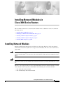
Installing Cisco 3800 Series Routers in an
Equipment Rack
This document describes how to install Cisco 3800 series integrated services routers in an equipment
rack. After mounting the router in the rack, you must connect the chassis to a reliable earth ground. These
procedures are described in the following sections:
•
Rack-Mounting the Router, page 10
•
Grounding the Router, page 14
Before working on your Cisco router, refer to the safety information in the “Safety Recommendations”
section on page 1 of “Preinstallation Requirements and Planning for Cisco 3800 Series Routers,” and in
the Cisco 2800 Series and Cisco 3800 Series Integrated Services Routers Regulatory Compliance and
Safety Information document that accompanied the router.
Note
Cisco 3800 series routers are not designed to be placed on a desktop or table.
Cisco 3800 series routers are shipped with network modules, WAN interface cards (WICs), voice
interface cards (VICs), power supplies, and other optional equipment that you ordered already installed.
If you need to remove or install these or other items, we recommend that you do so before installing the
router in a rack, when you have the best access and do not need to disconnect it from the network. For
procedures, see the following documents:
•
Installing Network Modules in Cisco 3800 Series Routers
•
Installing Interface Cards in Cisco 3800 Series Routers
•
Installing and Upgrading Internal Components in Cisco 3800 Series Routers
You will also be able to remove and install components while the router is in the rack, with the following
exceptions for the Cisco 3825 router:
•
SDRAM memory
•
Advanced integration modules (AIMs)
•
Packet voice data modules (PVDMs)
•
Internal power supply
Installing Cisco 3800 Series Routers in an Equipment Rack
OL-5969-01
9
Rack-Mounting the Router
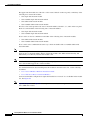
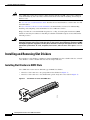
Rack-Mounting the Router
Mount the router in the equipment rack before making network and power connections.
Warning
To prevent personal injury or damage to the chassis, never attempt to lift or tilt the chassis using the
handles on modules (such as power supplies, fans, or cards); these types of handles are not designed
to support the weight of the unit. Statement 1032
Caution
To prevent damage to the router, never attempt to lift or tilt it by the plastic panel (bezel) on the front.
Always hold the router by the metal body.
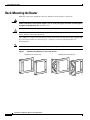
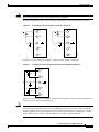
Cisco 3800 series routers can be installed in 19-inch and 23-inch racks using the brackets supplied with
the router. These brackets are shown in Figure 1 and Figure 2. The left and right brackets are
interchangeable.
Note
Mounting the routers in a 23-inch rack requires a bracket adapter from the rack manufacturer.
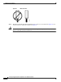
Figure 1
Rack-Mounting Brackets for Cisco 3825 Routers
Bracket pair for 23-inch rack
111818
Bracket pair for 19-inch rack
Installing Cisco 3800 Series Routers in an Equipment Rack
10
OL-5969-01
Rack-Mounting the Router
Figure 2
Rack-Mounting Brackets for Cisco 3845 Routers
Bracket pair for 23-inch rack
117982
Bracket pair for 19-inch rack
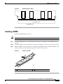
You can mount the router in the following ways:
•
Center mounting—Brackets attached in the center of the router with either the front panel or the rear
panel facing forward
•
Front mounting—Brackets attached at the front of the router with the front panel facing forward
•
Rear mounting—Brackets attached at the rear of the router with the rear panel facing forward
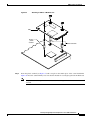
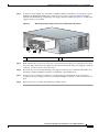
Attaching Brackets to the Router for Rack Mounting
Attach the mounting brackets to the router, using a number 2 Phillips screwdriver to install the screws
provided with the brackets. Figure 3 through Figure 6 show bracket attachment locations, using a
Cisco 3845 router as an example.
Caution
Do not overtorque the screws. The recommended torque is 10–12 inch-lb (1.1–1.4 N-m) for the
Cisco 3825 router and 15–18 inch-lb (1.7–2.0 N-m) for the Cisco 3845 router.
Caution
Your installation must allow unrestricted airflow for router cooling.
Installing Cisco 3800 Series Routers in an Equipment Rack
OL-5969-01
11
Rack-Mounting the Router
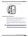
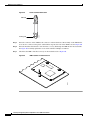
Figure 3
Bracket Installation for Front Mounting
Left bracket
for 23-inch rack
Left bracket
for 19-inch rack
Use six screws on each side.
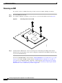
Bracket Installation for Rear Mounting
117984
Figure 4
Right bracket
for 19-inch rack
Right bracket
for 23-inch rack
NMESW16
15x
FastEtherne
t Ports
8x
7x
15x 7x
Ext
Pwr
14x
-48V
6x
13x
5x
12x
4x
11x 3x
10x
2x
9x
0x
1x
8x
GE
10/100
1000 /
Base-T
x
EN
0x
Left bracket
for 23-inch rack
Left bracket
for 19-inch rack
Right bracket
for 19-inch rack
Use six screws on each side.
Right bracket
for 23-inch rack
Installing Cisco 3800 Series Routers in an Equipment Rack
12
OL-5969-01
Rack-Mounting the Router
Bracket Installation for Center Mounting with Front Panel Forward
117985
Figure 5
Left bracket
for 23-inch rack
Left bracket
for 19-inch rack
Right bracket
for 19-inch rack
Right bracket
for 23-inch rack
Use six screws on each side.
Bracket Installation for Center Mounting with Rear Panel Forward
117986
Figure 6
NMESW16
15x
FastEtherne
t Ports
8x
7x
15x 7x
Ext
Pwr
14x
-48V
6x
13x
5x
12x
4x
11x 3x
10x
2x
9x
0x
1x
8x
GE
10/100
1000 /
Base-T
x
EN
0x
Left bracket
for 23-inch rack
Left bracket
for 19-inch rack
Right bracket
for 19-inch rack
Use six screws on each side.
Right bracket
for 23-inch rack
Installing the Router in a Rack
Warning
To prevent bodily injury when mounting or servicing this unit in a rack, you must take special
precautions to ensure that the system remains stable. The following guidelines are provided to ensure
your safety:
This unit should be mounted at the bottom of the rack if it is the only unit in the rack.
When mounting this unit in a partially filled rack, load the rack from the bottom to the top with the heaviest component
at the bottom of the rack.
If the rack is provided with stabilizing devices, install the stabilizers before mounting or servicing the unit in the rack.
Statement 1006
Installing Cisco 3800 Series Routers in an Equipment Rack
OL-5969-01
13
Grounding the Router
Install the router in the rack, using two screws for each side. Rack-mounting screws should be supplied
with the rack; they are not provided with the router.
Caution
Tip
Be sure to leave space above and below each router in a rack, to allow for cooling air circulation.
Start the lower pair of screws first. Rest the brackets on the lower screws while you insert the upper pair
of screws.
Attaching the Optional Cable Management Bracket
The optional cable management bracket (Cisco 3825 router only) provides attachment points for
organizing and routing cables. Attach the cable management bracket to the left or right rack-mount
bracket using the screw provided. You can attach the cable management bracket to either the upper or
lower threaded hole. See Figure 7 for attachment locations.
Figure 7
NMDESW36
Attaching the Optional Cable Management Bracket
35x
GE1
FastEthe
rnet Port
s
10/100/100
Base-Tx 0
17x
NMESW16
35x 17x
34x 16x
33x 15x
15x
32x 14x
31x 13x
FastEthern
et Ports
30x 12x
29x 11x
18x
28x 10x
27x 9x
8x
7x
Ext
Pwr
-48V
14x
6x
13x
5x
12x
4x
11x 3x
10x
2x
9x
0x
1x
8x
GE
10/100/
1000
Base-Tx
26x
8x
Ext
Pwr
25x
17
24x
-48V
6x
23x
5x
22x
4x
21x 3x
20x
2x
19x
0x
1x
18x
GE0
10/100/
1000
Base-Tx
EN
0x
EN
0x
117775
15x 7x
Cable management bracket.
Either edge may go up. Attach
to either side of the chassis.
Grounding the Router
Warning
This equipment must be grounded. Never defeat the ground conductor or operate the equipment in the
absence of a suitably installed ground conductor. Contact the appropriate electrical inspection
authority or an electrician if you are uncertain that suitable grounding is available. Statement 1024
Warning
During this procedure, wear grounding wrist straps to avoid ESD damage to the card. Do not directly
touch the backplane with your hand or any metal tool, or you could shock yourself. Statement 94
Installing Cisco 3800 Series Routers in an Equipment Rack
14
OL-5969-01
Grounding the Router
You must connect the router chassis to a reliable earth ground. The ground wire must be installed in
accordance with local electrical safety standards.
•
For NEBS-compliant grounding, use size AWG 6 (13 mm2) wire and the two-hole barrel lug
provided in the router accessory kit.
•
For NEC-compliant grounding, use size AWG 14 (2 mm2) or larger wire and an appropriate
user-supplied ring terminal.
•
For EN/IEC 60950-compliant grounding, use size AWG 18 (1 mm2) or larger wire and an
appropriate user-supplied ring terminal.
To connect the router to a reliable earth ground, follow these steps:
Step 1
Strip one end of the ground wire to the length required for the two-hole barrel lug or terminal.
•
For the NEBS two-hole barrel lug, approximately 0.75 in. (20 mm)
•
For a user-provided ring terminal, as required
Step 2
Crimp the ground wire to the two-hole barrel lug or ring terminal, using a crimping tool of the
appropriate size.
Step 3
Attach the two-hole barrel lug or ring terminal to the router chassis as shown in Figure 8 , Figure 9,
Figure 10, or Figure 11. For a two-hole barrel lug, use the two screws with captive locking washers
provided. For a ring terminal, use one of the screws provided. Tighten the screws to a torque of 8 to 10
in-lb (0.9 to 1.1 N-m).
Step 4
Connect the other end of the ground wire to a suitable grounding point at your site.
Figure 8
NMDESW36
NEBS-Compliant Two-Hole Barrel Lug Ground Connection on Cisco 3825 Router
35x
GE1
FastEthe
rnet Port
s
10/100/100
Base-Tx 0
17x
34x 16x
33x 15x
32x 14x
31x 13x
30x 12x
29x 11x
18x
28x 10x
27x 9x
26x 8x
Ext
Pwr
25x 17
24x 6x
-48V
23x 5x
22x 4x
21x 3x
20x 2x
19x 1x
0x
GE0
10/100/
1000
Base-Tx
EN
18x 0x
117015
35x 17x
Ground lug
attachment
Installing Cisco 3800 Series Routers in an Equipment Rack
OL-5969-01
15
Grounding the Router
Figure 9
NMESW16
NEBS-Compliant Two-Hole Barrel Lug Ground Connection on Cisco 3845 Router
15x
FastEthe
rnet Port
s
8x
7x
Ext
Pwr
-48V
14x
6x
13x
5x
12x
4x
11x 3x
10x 2x
9x
GE
10/10
1000 0/
Base-Tx
0x
1x
8x
EN
0x
122284
15x 7x
Ground lug
attachment
Figure 10
NMDESW36
Ring Terminal Ground Connection on Cisco 3825 Router
35x
GE1
FastEthe
rnet Ports
10/100/100
Base-Tx 0
17x
34x 16x
33x 15x
32x 14x
31x 13x
30x 12x
29x 11x
18x
28x 10x
27x 9x
26x
8x
Ext
Pwr
25x
17
24x
-48V
6x
23x
5x
22x
4x
21x 3x
20x
2x
19x
0x
1x
18x
GE0
10/100/
1000
Base-Tx
EN
0x
117014
35x 17x
Ring terminal
attachment
Installing Cisco 3800 Series Routers in an Equipment Rack
16
OL-5969-01
Grounding the Router
Figure 11
NMESW16
Ring Terminal Ground Connection on Cisco 3845 Router
15x
FastEthe
rnet Port
s
8x
7x
Ext
Pwr
14x
-48V
6x
13x
5x
12x
4x
11x 3x
10x
2x
9x
0x
1x
8x
GE
10/10
1000 0/
Base-Tx
EN
0x
103929
15x 7x
Ring terminal
attachment
After the router has been installed and grounded, you can connect power cables; WAN, LAN, and voice
cables; and cables for administrative access, as required for your installation. For cable connection
procedures, see these sections of the “Connecting Cables to Cisco 3800 Series Routers” document:
•
Power Connections, page 19
•
Connecting WAN, LAN, and Voice Cables, page 28
•
Connecting a Console or Modem, page 29
Installing Cisco 3800 Series Routers in an Equipment Rack
OL-5969-01
17
Grounding the Router
Installing Cisco 3800 Series Routers in an Equipment Rack
18
OL-5969-01
Connecting Cables to Cisco 3800 Series Routers
This document describes how to connect your Cisco 3800 series integrated services router to a power
source and to networks and external devices. It includes the following sections:
•
Power Connections, page 19
•
Connecting WAN, LAN, and Voice Cables, page 28
•
Connecting a Console or Modem, page 29
Warning
Only trained and qualified personnel should be allowed to install, replace, or service this equipment.
Statement 1030
Warning
This unit is intended for installation in restricted access areas. A restricted access area can be
accessed only through the use of a special tool, lock and key, or other means of security.
Statement 1017
Warning
Do not work on the system or connect or disconnect cables during periods of lightning activity.
Statement 1001
Power Connections
This section explains how to connect AC or DC power inputs to Cisco 3825 and Cisco 3845 routers. It
covers the following topics:
Warning
Note
•
Connecting Routers to AC Power, page 20
•
Connecting Routers to DC Power, page 20
•
Connecting Routers to Backup Power, page 27
Read the installation instructions before connecting the system to the power source. Statement 1004
The installation must comply with all required electrical codes applicable at the installation site.
Connecting Cables to Cisco 3800 Series Routers
OL-5970-02
19
Power Connections
Connecting Routers to AC Power
If your router uses AC power, connect it to a 15 A, 120 VAC (or 10 A, 240 VAC) circuit with overcurrent
protection. If backup power is required, see the “Connecting Routers to Backup Power” section on
page 27.
Note
The input voltage tolerance limits for AC power are 85 and 264 VAC.
Warning
AC connected units must have a permanent ground connection in addition to the power cable ground
wire. NEBS-compliant grounding satisfies this requirement. Statement 284
Warning
This product requires short-circuit (overcurrent) protection, to be provided as part of the building
installation. Install only in accordance with national and local wiring regulations. Statement 1045
The following warning applies to both AC power supplies and AC power supplies with IP phone power
in the Cisco 3825 router:
Warning
This product relies on the building’s installation for short-circuit (overcurrent) protection. Ensure that
the protective device is rated not greater than:
120 VAC, 45 A (240 VAC, 30 A). Statement 1005
The following warning applies to both AC power supplies and AC power supplies with IP phone power
in the Cisco 3845 router:
Warning
This product relies on the building’s installation for short-circuit (overcurrent) protection. Ensure that
the protective device is rated not greater than:
120 VAC, 30 A (240 VAC, 20 A). Statement 1005
Connecting Routers to DC Power
If your router has a DC-input power supply, follow the directions in this section for proper wiring. If
backup power is required, see the “Connecting Routers to Backup Power” section on page 27.
DC Wiring Requirements for Cisco 3800 Series Routers
Warning
Use copper conductors only. Statement 1025
Warning
This product requires short-circuit (overcurrent) protection, to be provided as part of the building
installation. Install only in accordance with national and local wiring regulations. Statement 1045
Connecting Cables to Cisco 3800 Series Routers
20
OL-5970-02
Power Connections
The following warning applies to the Cisco 3825 router only:
Warning
This product relies on the building’s installation for short-circuit (overcurrent) protection. Ensure that
the protective device is rated not greater than:
60 VDC, 20 A. Statement 1005
The following warning applies to the Cisco 3845 router only:
Warning
This product relies on the building’s installation for short-circuit (overcurrent) protection. Ensure that
the protective device is rated not greater than:
60 VDC, 30 A. Statement 1005
Table 2 and Table 3 summarize DC wiring requirements for Cisco 3825 and Cisco 3845 routers.
For a Cisco 3845 router, the safety ground wire connection must be at the same potential as the 0 V
(return) connection.
Table 2
DC Wiring Requirements for Cisco 3825 Routers
DC Input1
DC Input Wire Size
24–36 VDC, 12 A, positive or
negative, single or dual source
AWG 14 (2.0 mm2)
Safety Ground
Wire Size
Wire Terminal (Lug)
Overcurrent
Protection
AWG 14 (2.0 mm2), Amp/Tyco No. 32957 20 A
minimum
or equivalent
36–60 VDC, 8 A, positive or negative,
single or dual source
1. The input voltage tolerance limits for DC power are 18 and 72 VDC.
Table 3
DC Wiring Requirements for Cisco 3845 Routers
DC Input1
DC Input
Wire Size
Safety Ground
Wire Size
24–36 V, 19 A, positive or negative,
single or dual source
AWG 12
(3.0 mm2)
AWG 12 (3.0 mm2) Amp/Tyco No. 34852 or 30 A
minimum
equivalent
36–60 V, 13 A, positive or negative,
single or dual source
AWG 12 or 14
(3.0 or 2.0 mm2)
20–30 A
AWG 12 (3.0 mm2) AWG 12: Amp/Tyco
minimum
No. 34852 or equivalent
Wire Terminal (Lug)
Overcurrent
Protection
AWG 14: Amp/Tyco
No. 32957 or equivalent
1. The input voltage tolerance limits for DC power are 18 and 72 VDC.
Connecting Cables to Cisco 3800 Series Routers
OL-5970-02
21
Power Connections
DC Input Wiring Procedure
To connect the router to a DC power source, follow these steps:
Step 1
Warning
Tip
Remove power from the DC circuit. To ensure that power is removed from the DC circuit, locate the
circuit breaker for the DC circuit, switch the circuit breaker to the OFF position, and tape the
circuit-breaker switch in the OFF position.
Before performing any of the following procedures, ensure that power is removed from the DC circuit.
Statement 1003
Secure all power cabling when installing this unit to avoid disturbing field-wiring connections.
Warning
When stranded wiring is required, use approved wiring terminations, such as closed-loop or
spade-type with upturned lugs. These terminations should be the appropriate size for the wires and
should clamp both the insulation and conductor. Statement 1002
Step 2
Strip the wires to the appropriate length for the terminals. The length is 3/16 to 1/4 inch (5 to 6 mm) for
Amp/Tyco number 32957 terminals and 5/16 to 3/8 inch (8 to 9 mm) for Amp/Tyco number 34852
terminals.
Step 3
Crimp the terminals onto the DC power input and safety ground wires.
Step 4
Remove the plastic covers from the terminal block. Save the covers for reinstallation after you finish
wiring.
Step 5
Connect the wires to the terminal block, starting with the safety ground wire. Connect each wire to the
appropriate terminal as shown in Figure 12.
Warning
The illustration shows the DC power supply terminal block. Wire the DC power supply as illustrated.
The proper wiring sequence is ground to ground, positive to positive, and negative to negative. The
ground wire should always be connected first and disconnected last. Statement 239
Warning
An exposed wire lead from a DC-input power source can conduct harmful levels of electricity. Be sure
that no exposed portion of the DC-input power source wire extends from the terminal block plug.
Statement 122
Caution
Do not overtorque the terminal block screws. The recommended torque is 10.0 ± 0.5 in-lb
(1.1 ± 0.05 N-m).
Connecting Cables to Cisco 3800 Series Routers
22
OL-5970-02
Power Connections
DC Power Connections for Cisco 3825 Routers
-DC, input A
Return, input A
Safety ground
Return, input B
-DC, input B
Return, input A
+DC, input A
Safety ground
+DC, input B
Return, input B
A
+
+
A +
B
Negative DC input
Figure 13
Positive DC input
DC Power Connections for Cisco 3845 Routers
Negative DC input
24-60
Step 6
Warning
+ B
111752
Terminal
block
Terminal
block
Positive DC input
19-8 A
24-60
19-8 A
117981
Figure 12
Safety ground
Safety ground
Negative polarity input
0V (return)
0V (return)
Positive polarity input
Install the plastic cover over the terminals. (See Figure 14.)
The safety cover is an integral part of the product. Do not operate the unit without the safety cover
installed. Operating the unit without the cover in place will invalidate the safety approvals and pose
a risk of fire and electrical hazards. Statement 117
Step 7
Organize and bundle the wires using cable ties as shown in Figure 14 or Figure 15.
Step 8
If you are installing a second DC power supply, repeat Step 1 through Step 7 for the second supply
(input B).
Step 9
Turn on power to the DC circuit. Be sure to remove tape used to secure the circuit-breaker switch in the
OFF position.
Connecting Cables to Cisco 3800 Series Routers
OL-5970-02
23
Power Connections
Figure 14
COMPACT
DC Wire Routing and Attachment for Cisco 3825 Router
1
FLASH
0
ACT
SYS
PWR
RPS
AUX
PWR
AIM0
AIM1
PVDM0
PVDM1
PVDM2
PVDM3
117120
SYS
Plastic covers
Figure 15
Cable tie
DC Wire Routing and Attachment for Cisco 3845 Router
SYS
ACT SYS
AUX SYS
PWR1 PW
R1 PWR2 AUX
PWR2
117046
Plastic cover
Cable tie
Dual DC Power Supply Configuration in Cisco 3825 Routers
You can connect a single DC power source to either the A input or the B input. If there are dual power
sources, connect one source to the A input and one source to the B input. Both sources must have the
same polarity (with respect to ground) and voltage (within 0.25 V). Do not connect –DC-grounded and
+DC-grounded dual sources to a Cisco 3825 router.
Connecting Cables to Cisco 3800 Series Routers
24
OL-5970-02
Power Connections
Caution
Dual sources with opposite-polarity grounding damage equipment.
In Figure 16, either the positive source terminal or the negative source terminal is tied to ground.
Connecting to One Source Only—Source A or Source B
A-
+
A-
+
A+
A+
B+
B+
B-
B-
127037
Figure 16
In Figure 17, source A and source B share common negative terminal connections.
Figure 17
Connecting Source A and Source B with Common Negative Terminals
A-
+
Va
A+
+
B+
B-
127039
Vb
In Figure 18, source A and source B share common positive terminal connections. This configuration is
allowed only if Va equals Vb (within 0.25 V).
Caution
If source A and source B are wired with common positive terminals and their voltages are unequal by
more than 0.25 V, the higher-voltage source can discharge into the lower-voltage source through the
negative terminals. Excessive discharging currents through these terminals can actuate one or both of
the dual- input DC power supply’s internal A– or B– fuses, resulting in lack of redundancy or system
failure. When source A and source B are within 0.25 V, discharge current is minimal.
Connecting Cables to Cisco 3800 Series Routers
OL-5970-02
25
Power Connections
Note
When source A and source B are wired with common negative terminals, as in Figure 17, discharging
does not occur and there is no requirement that source A and source B voltages be equal.
Figure 18
Connecting Source A and Source B with Common Positive Terminals
Va voltage = Vb voltage (greater than 0.25 V)
Va voltage = Vb voltage (within 0.25 V)
AVa
A+
+
B+
+
Va
A+
+
Vb
B+
Vb
B-
B-
127040
+
A-
In Figure 19, source A and source B are wired with opposite polarity grounds. Do not use this
configuration.
Caution
Do not use the DC input configuration shown in Figure 19.
Connecting Cables to Cisco 3800 Series Routers
26
OL-5970-02
Power Connections
Figure 19
Source A and Source B Wired with Opposite-Polarity Grounds
A-
+
Va
A+
+
B+
B-
127041
Vb
Connecting Routers to Backup Power
The Cisco 3845 router accommodates two hot-swappable power supplies in bays at the front of the
router. A single power supply meets router requirements. The second power supply provides
redundancy, load sharing, and increased router availability. Either power supply can be removed without
affecting router operation. Any combination of two power supplies is permitted.
For instructions for installing a second power supply in a Cisco 3845 router, see the “Installing and
Upgrading Internal Components in Cisco 3800 Series Routers” section.
The Cisco 3825 router has one internal power supply and provides a connector to an optional
Cisco Redundant Power System (RPS) external backup source. Figure 20 and Figure 21 illustrate this
connection. Use a flat-blade screwdriver to pry off the door over the RPS connector before connecting
the cable. See the Cisco RPS-675 Hardware Installation Guide for complete RPS power connection
instructions.
Caution
Before connecting the RPS to the router, make sure that either the RPS is in standby mode or the RPS
AC power is disconnected. Connecting the RPS to AC power automatically places the RPS in
active mode.
Connecting Cables to Cisco 3800 Series Routers
OL-5970-02
27
Connecting WAN, LAN, and Voice Cables
Figure 20
RPS Connector on Cisco 3825 Router
R
FLASH
1
0
SYS
AUX
ACT
RPS
IP PWR
AIM0
AIM1
121273
COMPACT
PVDM0
PVDM1
PVDM2
PVDM3
RPS connector
Figure 21
Connecting RPS to Cisco 3825 Router
R
FLASH
1
0
SYS
ACT
SYS
PWR
RPS
AUX
PWR
AIM0
AIM1
PVDM0
PVDM1
PVDM2
PVDM3
121292
COMPACT
Connecting WAN, LAN, and Voice Cables
This section describes how to connect WAN, LAN, and voice interface cables to your Cisco 3800 series
integrated services router.
One Ethernet cable is provided with the router for a Gigabit Ethernet connection. These ports use
Category 5, 5e, or 6 UTP 1000BASE-T cable. Additional cables and transceivers can be ordered from
Cisco. For ordering information, see the Cisco Product Catalog at
http://www.cisco.com/en/US/partner/products/index.html.
Connect each WAN, LAN, or voice cable to the appropriate connector on the router or on a network
module or interface card, following these precautions:
•
Position the cables carefully, so that they do not put strain on the connectors.
•
Organize cables in bundles so that they do not tangle.
•
Inspect the cables to make sure that the routing and bend radiuses are satisfactory. Reposition cables
if necessary.
•
Install cable ties in accordance with site requirements.
Cable connections to network modules and interface cards are described in detail in the following
documents:
•
Cisco Network Modules Hardware Installation Guide
•
Cisco Interface Cards Installation Guide
Connecting Cables to Cisco 3800 Series Routers
28
OL-5970-02
Connecting a Console or Modem
For cable pinouts, see the Cisco Modular Access Router Cable Specifications document.
Warning
Do not work on the system, or connect or disconnect cables during periods of lightning activity.
Statement 1001
Warning
The ISDN connection is regarded as a source of voltage that should be inaccessible to user contact.
Do not attempt to tamper with or open any public telephone operator (PTO)-provided equipment or
connection hardware. Any hardwired connection (other than by a nonremovable,
connect-one-time-only plug) must be made only by PTO staff or suitably trained engineers.
Statement 23
Warning
To avoid electric shock, do not connect safety extra-low voltage (SELV) circuits to telephone-network
voltage (TNV) circuits. LAN ports contain SELV circuits, and WAN ports contain TNV circuits. Some
LAN and WAN ports both use RJ-45 connectors. Use caution when connecting cables. Statement 1021
Warning
Hazardous network voltages are present in WAN ports regardless of whether power to the router is
OFF or ON. To avoid electric shock, use caution when working near WAN ports. When detaching
cables, detach the end away from the router first. Statement 1026
Connecting a Console or Modem
Cisco 3800 series routers provide EIA/TIA-232 asynchronous serial console and auxiliary ports. These
ports provide administrative access to the router either locally, using an ASCII terminal or PC running
HyperTerminal or similar terminal emulation software connected to the console port, or remotely, using
a modem connected to the auxiliary port.
The principal difference between the console and auxiliary ports is that the auxiliary port supports
hardware flow control, but the console port does not. Flow control paces the transmission of data
between a sending device and a receiving device, ensuring that the receiving device can absorb the data
sent to it before the sending device sends more. When the buffers on the receiving device are full, a
message is sent to the sending device to suspend transmission until the data in the buffers has been
processed.
Because the auxiliary port supports flow control, it is best suited for use with the high-speed
transmissions of a modem. Terminals send data at slower speeds than modems; therefore, the console
port is best suited for use with terminals.
Cisco provides the following cables and adapters for connecting the router to a console or modem:
•
Console adapter cable (RJ-45-to-DB-9, light blue)
•
Modem adapter cable (RJ-45-to-DB-25, black)
Connecting Cables to Cisco 3800 Series Routers
OL-5970-02
29
Connecting a Console or Modem
This section describes how to connect a console to the console port and how to connect a modem to the
auxiliary port.
Connecting a Console to the Console Port
To connect a console (ASCII terminal or a PC running HyperTerminal or similar terminal emulation
software) to the console port on the router, follow these steps:
Step 1
Use the blue RJ-45-to-DB-9 console adapter cable to connect the router to a terminal. (See Figure 22
and Figure 23.)
For information about cable pinouts, see the Cisco Modular Access Router Cable Specifications
document.
On Cisco routers, the console port is color-coded blue.
Note
Step 2
Configure your terminal or terminal emulation software for a data rate of 9600 bps, 8 data bits, no parity,
and 1 stop bit.
Because hardware flow control is not possible on the console port, Cisco does not recommend
connecting modems to this port. Always connect modems to the auxiliary port.
Note
Figure 22
NMDESW36
Connecting a Computer to the Cisco 3825 Router Console Port
35x
GE1
FastEthe
rnet Ports
17x
35x 17x
34x 16x
33x 15x
32x 14x
31x 13x
30x 12x
29x 11x
18x
28x 10x
27x 9x
26x
8x
Ext
Pwr
25x
17
24x
-48V
6x
23x
5x
22x
4x
21x 3x
20x
2x
19x
0x
1x
18x
GE0
10/100/
1000
Base-Tx
EN
0x
117776
10/100/100
Base-Tx 0
Console port
connector (RJ-45)
Laptop computer
Connecting Cables to Cisco 3800 Series Routers
30
OL-5970-02
Connecting a Console or Modem
Figure 23
Connecting a Computer to the Cisco 3845 Router Console Port
117777
Console port
connector
(RJ-45)
Laptop computer
Connecting a Modem to the Auxiliary Port
To connect a modem to the auxiliary port on the router, follow these steps:
Step 1
Use the black RJ-45-to-DB-25 modem adapter cable to connect the router to a modem. (See Figure 24
and Figure 25.)
Step 2
Make sure that your modem and the router auxiliary port are configured for the same transmission speed
(up to 115,200 bps is supported) and hardware flow control, with data carrier detect (DCD) and data
terminal ready (DTR) enabled.
Connecting Cables to Cisco 3800 Series Routers
OL-5970-02
31
Connecting a Console or Modem
Figure 24
NMDESW36
Connecting a Modem to the Auxiliary Port on a Cisco 3825 Router
35x
GE1
FastEthe
rnet Ports
10/100/100
Base-Tx 0
17x
34x 16x
33x 15x
32x 14x
31x 13x
30x 12x
29x 11x
18x
28x 10x
27x 9x
26x
8x
Ext
Pwr
25x
17
24x
-48V
6x
23x
5x
22x
4x
21x 3x
20x
2x
19x
0x
1x
18x
GE0
10/100/
1000
Base-Tx
EN
0x
117778
35x 17x
AUX port
connector
(RJ-45)
Modem
Figure 25
Connecting a Modem to the Auxiliary Port on a Cisco 3845 Router
117779
AUX port
connector
(RJ-45)
Modem
Connecting Cables to Cisco 3800 Series Routers
32
OL-5970-02
Powering Up Cisco 3800 Series Routers
This document describes how to power up your Cisco 3800 series integrated services router.
Caution
Warning
To ensure adequate cooling, electromagnetic interference (EMI) reduction, and safety, never operate the
router unless the cover and all modules and cover plates are installed.
The plug-socket combination must be accessible at all times because it serves as the main
disconnecting device. Statement 1019
This document contains the following sections:
•
Prerequisites, page 33
•
Power-Up Procedure, page 34
Prerequisites
Before you power up the router, make sure you have done the following:
Note
•
Securely mounted and grounded the router. See “Installing Cisco 3800 Series Routers in an
Equipment Rack” for instructions.
•
Connected power and interface cables. See “Connecting Cables to Cisco 3800 Series Routers.”
•
Connected a PC running HyperTerminal or a similar terminal emulation program to the console port,
configured for 9600 bps, 8 data bits, 1 stop bit, no flow control, and no parity. See the “Connecting
a Console or Modem” section on page 29 of “Connecting Cables to Cisco 3800 Series Routers.”
For initial power-up, a direct console connection is recommended. After the initial configuration is
completed, a remote modem connection can be used for router management.
•
Chosen passwords for access control.
•
Determined IP addresses for Ethernet and serial interfaces.
Powering Up Cisco 3800 Series Routers
OL-5971-01
33
Power-Up Procedure
Power-Up Procedure
To power up your router and verify that it has gone through its initialization and self-test, follow these
steps. After you are finished, the router is ready for software configuration.
Note
To view the boot sequence, you must have a console connection to the router before it powers up.
Step 1
Make sure that your PC is powered up and connected as described in the “Prerequisites” section on
page 33.
Step 2
Turn the router power switch on.
Step 3
The SYS LED on the front of the router immediately begins blinking green and the fans operate. On the
Cisco 3825 router, the SYS PWR LED shows steady green. The SYS PWR1 and SYS PWR2 LEDs on
the Cisco 3845 router do not come on yet.
If these events do not happen, see “Troubleshooting Cisco 3800 Series Routers.” Table 4 describes the
behavior of other LEDs during the power-up sequence.
Step 4
Startup messages appear on your console. When the startup messages end, the SYS LED shows a steady
green. The SYS PWR1 or SYS PWR2 LED on the Cisco 3845 router comes on (depending on which
power supply is installed).
Caution
Do not press any keys on the keyboard until the messages stop and the SYS LED is steady green. Any
keys pressed during this time are interpreted as the first command typed when the messages stop, which
might cause the router to reboot. It takes several minutes for the messages to stop.
Note
If the rommon 1> prompt appears, your router has booted in ROM monitor mode. For information on the
ROM monitor, see Using the ROM Monitor.
Verifying LED Indications
The LEDs described in Table 4 provide power, activity, and status information. For detailed information
about LEDs, see the “LEDs” section on page 41 of “Troubleshooting Cisco 3800 Series Routers.”
Note
The Cisco 3845 router has two SYS PWR and two AUX PWR LEDs. These LEDs do not come on until
the router has booted. Each power supply also has its own LED, which shows steady green to indicate
normal operation as soon as router power is turned on.
Powering Up Cisco 3800 Series Routers
34
OL-5971-01
Power-Up Procedure
Table 4
LED Indications During Power-up
LED Label
Color and State
Meaning
SYS
Off
Router not receiving power
Steady green
Normal operation (power-up complete)
Blinking green
Booting or in ROM monitor mode (immediately after power-up)
Amber
Powered but malfunctioning
Off
Router not receiving power
Steady green
Normal operation (immediately after power-up)
SYS PWR
(Cisco 3825)
SYS PWR1
Off
or SYS PWR2
(Cisco 3845) Steady green
Router not receiving power, power supply not present, or power-up not
completed
Normal operation of indicated power supply (power-up completed)
AUX PWR
(Cisco 3825)
AUX PWR1
AUX PWR2
(Cisco 3845)
Off
IP phone power off or not present, or power-up not completed
Steady green
Normal operation (power-up completed)
Amber
Powered but malfunctioning
ACT
Off
No packet activity or power-up not completed
Steady or blinking green
Packets transmitted or received on any WAN or LAN port, or router is
monitoring internal activities (power-up completed)
RPS
(Cisco 3825)
Off
Connected to primary power source or power-up not completed
Steady green
Connected to Cisco Redundant Power System (power-up completed)
CF
Off
CompactFlash memory card not being accessed
Steady green
CompactFlash memory card being accessed; do not eject
Blinking green
CompactFlash memory card being accessed; do not eject
Off
No link
Green
Ethernet cable present, link established
GE0: Speed
Blinking green
Blink frequency indicates port speed:
1 blink per second: 10 Mbps
2 blinks per second: 100 Mbps
3 blinks per second: 1000 Mbps
GE1: Link
Off
No link
Green
Ethernet cable present, link established
Blinking green
Blink frequency indicates port speed:
1 blink per second: 10 Mbps
2 blinks per second: 100 Mbps
3 blinks per second: 1000 Mbps
GE0: Link
GE1: Speed
Powering Up Cisco 3800 Series Routers
OL-5971-01
35
Power-Up Procedure
Verifying the Hardware Configuration
To display and verify hardware features, enter the following commands:
•
show version—Displays the system hardware version; the installed software version; the names and
sources of configuration files; the boot images; and the amount of installed DRAM, NVRAM, and
flash memory.
•
show diag—Lists and displays diagnostic information about the installed controllers, interface
processors, and port adapters; typical examples are network modules, interface cards (VICs, WICs,
HWICs), and advanced integration modules (AIMs).
After your router is powered up, you are ready to begin the initial software configuration. For basic
configuration procedures, see Cisco 3800 Series Software Configuration.
Setting the Date and Time
If the router has been exposed to nonoperating environmental conditions, its internal real-time clock
(RTC) may not display the correct date and time. To set the RTC manually, use one of the forms of the
calendar set command in EXEC mode:
calendar set hh:mm:ss day month year
calendar set hh:mm:ss month day year
Syntax Description
hh:mm:ss
Current time in hours (using 24-hour notation), minutes, and seconds.
day
Current day (by date) in the month.
month
Current month (by name).
year
Current year (no abbreviation).
The following example sets the RTC to 1:32 p.m. on November 19, 2004:
Router# calendar set 13:32:00 November 19 2004
Powering Up Cisco 3800 Series Routers
36
OL-5971-01
Troubleshooting Cisco 3800 Series Routers
Your Cisco 3800 series integrated services router goes through extensive testing and burn-in before
leaving the factory. If you encounter problems, use this document to help isolate problems or to
eliminate the router as the source of the problem.
This document contains the following sections:
Note
•
Solving Problems, page 38
•
LEDs, page 41
•
The show environment Command, page 45
•
Error Messages, page 46
•
Jumper Settings, page 48
•
Recovering a Lost Password, page 49
•
More Troubleshooting Help, page 49
To troubleshoot network modules, see the Cisco Network Modules Hardware Installation Guide. To
troubleshoot interface cards, see the Cisco Interface Cards Installation Guide. These documents are
available on Cisco.com.
If you cannot find the source of the problem, contact a customer service representative. For information
about obtaining technical support, see the “Obtaining Technical Assistance” section on page 12 of
“Introduction to Cisco 3800 Series Routers Hardware Documentation.” Before you call, have the
following information ready:
•
Router type and serial number (for serial number locations, see the “Product Identification” section
on page 5 of “Overview of Cisco 3800 Series Routers”)
•
Maintenance agreement or warranty information
•
Type of software and version number
•
Date you received the router
•
Brief description of the problem
•
Brief explanation of the steps taken to isolate the problem
Troubleshooting Cisco 3800 Series Routers
OL-5972-01
37
Solving Problems
Solving Problems
The key to solving problems is to isolate the problem to a specific subsystem by comparing what the
router is doing to what it should be doing.
The LEDs on the front and rear panel of the router enable you to determine router performance and
operation. LEDs are described in the “LEDs” section on page 41.
When solving problems, consider the following subsystems:
•
Power and cooling systems—External power source, power cable, router power supply and circuit
breaker, and router blower and fan. Also consider inadequate ventilation or air circulation.
•
Network modules and interface cards—LEDs on the modules and interface cards help identify a
failure.
•
Cables—External cables that connect the router to the network.
Troubleshooting the Power and Cooling Systems
Both the system power LED and the fans can help you troubleshoot a power problem. Check the
following items.
Note
The Cisco 3845 router has two system power LEDs, one for each power supply, labeled SYS PWR1 and
SYS PWR2.
Normal Indications
With the power switch on, normal indications are:
•
SYS LED steady green
•
SYS PWR LED steady green for the Cisco 3825 router, or SYS PWR1 or SYS PWR2 LED steady
green for the Cisco 3845 router (depending on which power supply is active)
•
Fans operating
Fault Indications
Check the following symptoms to locate or eliminate faults in the power and cooling systems:
•
With the power switch on, what color is the SYS LED?
– If the LED is steady green, the router is receiving power and is functional.
– If the LED is amber, the router is receiving power but is not functional.
– If the LED is off, check the power source and power cable.
•
With the power switch on, the SYS LED steady green, and the SYS PWR LED (Cisco 3825) or
SYS PWR1 or SYS PWR2 LED (Cisco 3845) steady green, do the fans operate?
– If yes, the power system is functioning.
– If no, check the fans.
Troubleshooting Cisco 3800 Series Routers
38
OL-5972-01
Solving Problems
•
With the power switch on and the SYS LED steady green, do the fans operate?
– If yes, the power system is functioning.
– If no, check the fans.
•
With the power switch on and the SYS PWR LED (Cisco 3825) or SYS PWR1 or SYS PWR2 LED
(Cisco 3845) off, do the fans operate?
– If yes, the router is receiving power. The fans are connected directly to the DC outputs of the
power supply.
– If no, check the power source and power cable.
•
Does the router shut down after being on a short time?
– Check for an environmentally induced shutdown. See the next section, “Environmental
Reporting Features.”
– Check the environmental site requirements in the “General Site Requirements” section on
page 3 of “Preinstallation Requirements and Planning for Cisco 3800 Series Routers.”
– Check for a power supply failure by inspecting the SYS PWR LED on the Cisco 3825 router,
or the SYS PWR1 or SYS PWR2 LED on the Cisco 3845 router (depending on which power
supply is active). If the LED is green, the power supply is functional.
•
Router partially boots, but LEDs do not come on.
– Check for a power supply failure by inspecting the SYS PWR LED on the Cisco 3825 router or
the SYS PWR1 LED or SYS PWR2 LED on the Cisco 3845 router (depending on which power
supply is active). If the LED is green, the power supply is functional.
– If the SYS PWR LED is not on, see the “Obtaining Technical Assistance” section on page 12
of “Introduction to Cisco 3800 Series Routers Hardware Documentation” for information about
customer service. For warranty information, see the “Cisco 90-Day Limited Hardware Warranty
Terms” section on page 10 of “Introduction to Cisco 3800 Series Routers Hardware
Documentation.”
Environmental Reporting Features
If the router is operating at an abnormally high temperature, the following message is displayed on the
console screen:
System detected OVERTEMPERATURE condition. Please resolve cooling problem immediately!
Some causes of abnormally high router temperature are:
•
Fan failure
•
Air conditioning failure in the room
•
Air blockage to cooling vents
Take steps to correct the problem. See also the “Site Environment” section on page 4 and the
“Equipment Racks” section on page 5 of “Preinstallation Requirements and Planning for Cisco 3800
Series Routers.”
Troubleshooting Cisco 3800 Series Routers
OL-5972-01
39
Solving Problems
Troubleshooting Modules, Cables, and Connections
Network problems can be caused by a module; cables or cable connections; or external devices such as
a modem, transceiver, hub, wall jack, WAN interface, or terminal. Check for the following symptoms to
help isolate the problem:
•
Network module or interface card is not recognized by the router.
– Make sure that the module or interface card is firmly seated in its slot.
– Check the LEDs on the module or interface card. For information on these LEDs, see the Cisco
Network Modules Hardware Installation Guide and the Cisco Interface Cards Installation
Guide.
– Make sure that you have a version of Cisco IOS software that supports the network module or
interface card. To determine which Cisco IOS releases support your router, network modules,
and interface cards, go to the Software Advisor at http://tools.cisco.com/Support/Fusion/. You
must have an account on Cisco.com.
•
Module or card is recognized, but interface ports do not initialize.
– Make sure that the module or card is firmly seated in its slot.
– Check external cable connections.
– Make sure that you have a version of Cisco IOS software that supports network module or
interface card. To determine which Cisco IOS releases support your router, network modules,
and interface cards, go to the Software Advisor at http://tools.cisco.com/Support/Fusion/. You
must have an account on Cisco.com.
•
Router does not boot properly, or constantly or intermittently reboots.
– Make sure that all modules are firmly seated in their slots.
– Check the router chassis or software. For information about customer service, see the
“Obtaining Technical Assistance” section on page 12 of “Introduction to Cisco 3800 Series
Routers Hardware Documentation.” For warranty information, see the “Cisco 90-Day Limited
Hardware Warranty Terms” section on page 10 of “Introduction to Cisco 3800 Series Routers
Hardware Documentation.”
•
Router boots, but the console screen is frozen.
– Check the external console connection.
– Verify that the parameters for your terminal are set as follows:
- The data rate matches the one configured for the router (9600 bps is the default)
- 8 data bits
- No parity
- 1 stop bit
•
Router powers on and boots only when a particular network module or interface card is removed.
– Check the network module or interface card. For information about customer service, see the
“Obtaining Technical Assistance” section on page 12 of “Introduction to Cisco 3800 Series
Routers Hardware Documentation.” For warranty information, see the “Cisco 90-Day Limited
Hardware Warranty Terms” section on page 10 of “Introduction to Cisco 3800 Series Routers
Hardware Documentation.”
Troubleshooting Cisco 3800 Series Routers
40
OL-5972-01
LEDs
Router powers on and boots only when a particular cable is disconnected.
•
– There may be a problem with the module, interface card, or cable. For information about
customer service, see the “Obtaining Technical Assistance” section on page 12 of “Introduction
to Cisco 3800 Series Routers Hardware Documentation.” For warranty information, see the
“Cisco 90-Day Limited Hardware Warranty Terms” section on page 10 of “Introduction to
Cisco 3800 Series Routers Hardware Documentation.”
LEDs
LEDs enable you to determine router performance and operation. Figure 26 and Figure 27 show the
LEDs on the Cisco 3825 router. Figure 28 and Figure 29 show the LEDs on the Cisco 3845 router. Each
power supply in a Cisco 3845 router also has its own LED.
For an explanation of these LEDs, see Table 5.
Figure 26
SYS
Cisco 3825 Front-Panel LEDs
ACT
SYS
PWR
AUX
PWR
RPS
AIM0
AIM1 PVDM0 PVDM1 PVDM2 PVDM3
R
FLASH
1
0
SYS
AUX
ACT
RPS
IP PWR
AIM0
AIM1
PVDM0
PVDM1
PVDM2
PVDM3
117780
COMPACT
Troubleshooting Cisco 3800 Series Routers
OL-5972-01
41
LEDs
Figure 27
Cisco 3825 Rear-Panel LEDs
CONSOLE SPD GE 1/0 LNK
AUX
NMDESW36
SPD GE 0/0 LNK
GE 0/0 SFP
35x
GE1
FastEthe
rnet Ports
10/100/100
0
Base-Tx
17x
NMESW16
35x 17x
34x 16x
33x 15x
15x
32x 14x
31x 13x
FastEthern
et Ports
30x 12x
29x 11x
18x
28x 10x
27x 9x
8x
7x
26x
8x
Ext
Pwr
25x
17
24x
Ext
Pwr
14x
6x
13x
5x
12x
4x
11x 3x
10x 2x
9x
0x
1x
8x
GE
10/100/
1000
Base-Tx
-48V
6x
23x
5x
22x
4x
21x 3x
20x
2x
19x
0x
1x
18x
GE0
10/100/
1000
Base-Tx
EN
0x
EN
0x
117782
15x 7x
-48V
Cisco 3845 Front-Panel LEDs
117781
Figure 28
Troubleshooting Cisco 3800 Series Routers
42
OL-5972-01
LEDs
Figure 29
Cisco 3845 Router Rear-Panel LEDs
GigE 0/1
SPD
LNK
SPD
LNK
PVDM 3 PVDM 2 PVDM 1 PVDM 0 AIM 1 AIM 0
CF
SFP
GigE 0/0
CONSOLE
AUX
PVDM 3
CF
SPD
PVDM 2
PVDM 1
GigE 0/1
LNK
PVDM 0
AIM 1
AIM 0
SPD
LNK
SFP
117783
GigE 0/0
Table 5
Cisco 3800 Series LED Indicators
LED
3825
3845
Color and State Meaning
SYS
Front
Front
Off
Router not receiving power
Steady green
Normal operation (power-up complete)
Blinking green Booting or in ROM monitor mode (immediately
after power-up)
ACT
SYS PWR
RPS
SYS PWR1
SYS PWR2
Front
Front
Front
—
—
Front
—
—
Front
Front
Amber
Powered but malfunctioning
Off
No packet activity
Steady or
blinking green
Packets transmitted or received on any WAN or
LAN port, or router is monitoring internal
activities (power-up completed)
Off
Router not receiving power
Steady green
Normal operation (immediately after power-up)
Off
Connected to primary power system
Steady green
Connected to redundant power system
Off
Router not receiving power, power supply 1 not
present, or power-up not completed
Steady green
Present and enabled (power-up completed)
Amber
Present and off or malfunctioning
Off
Router not receiving power, power supply 2 not
present, or power-up not completed
Steady green
Present and enabled (power-up completed)
Amber
Present and off or malfunctioning
Troubleshooting Cisco 3800 Series Routers
OL-5972-01
43
LEDs
Table 5
Cisco 3800 Series LED Indicators (continued)
LED
3825
3845
Color and State Meaning
AUX PWR
Front
—
Off
IP phone power off or not present, or power-up
not completed
Steady green
Present and enabled (power-up completed)
Amber
Powered but malfunctioning
Off
IP phone power supply 1 off or not present, or
power-up not completed
Steady green
Present and enabled (power-up completed)
Amber
Powered but malfunctioning
Off
IP phone power supply 2 off or not present, or
power-up not completed
Steady green
Present and enabled (power-up completed)
Amber
Powered but malfunctioning
Off
AIM0 not present
Green
Present and enabled
Amber
Present but malfunctioning
Off
AIM1 not present
Green
Present and enabled
Amber
Present but malfunctioning
Off
PVDM0 not present
Green
Present and enabled
Amber
Present but malfunctioning
Off
PVDM1 not present
Green
Present and enabled
Amber
Present but malfunctioning
Off
PVDM2 not present
Green
Present and enabled
Amber
Present but malfunctioning
Off
PVDM3 not present
Green
Present and enabled
Amber
Present but malfunctioning
Off
CompactFlash memory card not being accessed
Steady green
CompactFlash card being accessed; do not eject
AUX PWR1
AUX PWR2
AIM0
AIM1
PVDM0
PVDM1
PVDM2
PVDM3
CF
—
—
Front
Front
Front
Front
Front
Front
Front
Front
Front
Rear
Rear
Rear
Rear
Rear
Rear
Rear
Blinking green CompactFlash card being accessed; do not eject
SFP
GE0: Link
Rear
Rear
Rear
Rear
Off
SFP link not established
Green
SFP port active, link established
Off
No link
Green
Ethernet cable present, link established
Troubleshooting Cisco 3800 Series Routers
44
OL-5972-01
The show environment Command
Table 5
Cisco 3800 Series LED Indicators (continued)
LED
3825
3845
Color and State Meaning
GE0: Speed
Rear
Rear
Blinking green Blink frequency indicates port speed
1 blink per second: 10 Mbps
2 blinks per second: 100 Mbps
3 blinks per second: 1000 Mbps
GE1: Link
Rear
Rear
Off
No link
Green
Ethernet cable present, link established
GE1: Speed
Rear
Rear
Blinking green Blink frequency indicates port speed
1 blink per second: 10 Mbps
2 blinks per second: 100 Mbps
3 blinks per second: 1000 Mbps
PS1
—
Front
Off
Power supply 1 not present
Steady green
Present and enabled
Amber
Present and off or malfunctioning
Off
Power supply 2 not present
Steady green
Present and enabled
Amber
Present and off or malfunctioning
PS2
—
Front
The show environment Command
The show environment command can help you monitor and troubleshoot router power and ventilation
status.
This is an example of the output of the show environment command for a Cisco 3825 router with an
AC power supply and no Redundant Power System:
Router# show environment
Redundant Power System is not present.
SYS PS1 is present.
Type: AC
AUX (-48V) PS1 is absent.
Fan 1 Normal
Fan 2 Normal
Fan 3 Normal
Fan Speed is Normal
Alert settings:
Intake temperature warning: Enabled, Threshold: 50
Core temperature warning: Enabled, Threshold: 70 (CPU: 95)
Board Temperature: Normal
Internal-ambient temperature = 29, Normal
CPU temperature = 46, Normal
Intake temperature = 31, Normal
Voltage 1(3300) is Normal, Current voltage = 3316 mV
Voltage 2(5150) is Normal, Current voltage = 5210 mV
Voltage 3(2500) is Normal, Current voltage = 2525 mV
Voltage 4(1200) is Normal, Current voltage = 1191 mV
Troubleshooting Cisco 3800 Series Routers
OL-5972-01
45
Error Messages
This is an example of the output of the show environment command for a Cisco 3845 router that has
one AC power supply with IP phone power output installed:
Router# show environment
SYS PS1 is present
Fan status: Normal
Input Voltage status: Normal
DC Output Voltage status: Normal
Type: AC
Thermal status: Normal
SYS PS2 is absent
AUX (-48V) PS1 is present
AUX (-48V) PS2 is absent
Fan 1 Normal
Fan 2 Normal
Fan 3 Normal
Fan Speed is Normal
Alert settings:
Intake temperature warning: Enabled, Threshold: 50
Core temperature warning: Enabled, Threshold: 70 (CPU: 90)
Board Temperature: Normal
Internal-ambient temperature = 31, Normal
CPU temperature = 50, Normal
Intake temperature = 25, Normal
Backplane temperature = 24, Normal
Voltage 1(3300) is Normal, Current voltage = 3284 mV
Voltage 2(5150) is Normal, Current voltage = 5210 mV
Voltage 3(2500) is Normal, Current voltage = 2549 mV
Voltage 4(1200) is Normal, Current voltage = 1215 mV
Error Messages
This section describes error messages that may appear on an external console screen. (For more
information about consoles, see the “Connecting a Console or Modem” section on page 29 of
“Connecting Cables to Cisco 3800 Series Routers.”)
Cisco IOS software checks the system once every 30 seconds. If an error still exists, the error message
is displayed again; if the error has cleared, a recovery message is displayed.
Error Message System detected OVERTEMPERATURE condition. Please resolve cooling
problem immediately!
Explanation The router is operating at a temperature higher than the user-set threshold, possibly
caused by fan failure, air-conditioning failure in the room, or air blockage to cooling vents.
Recommended Action Make sure that the ambient room temperature does not exceed 40 degrees C
and that airflow to the router is not blocked. See the “Site Environment” section on page 4 and the
“Equipment Racks” section on page 5 of “Preinstallation Requirements and Planning for
Cisco 3800 Series Routers.”
If this condition persists, the power-supply thermal monitor automatically shuts down the router.
Call your Cisco technical support representative for help, if necessary.
Troubleshooting Cisco 3800 Series Routers
46
OL-5972-01
Error Messages
Error Message Fan 1|2|3 had a rotation error reported.
Explanation The specified fan is not rotating at the desired speed.
Recommended Action If this error is detected, the router system software automatically increases the
fan speed to high. If the rotation error disappears, fan speed is kept at high. If this error appears
repeatedly, there is something wrong with the fan. The error will reappear until action is taken.
Error Message Voltage 1|2|3|4 (3300 mv|5150 mv|2500 mv|1200 mv) has exceeded
recommended operating limits.
Explanation One of the internal voltage outputs is outside its operating limits.
Recommended Action System failure. See the “Obtaining Technical Assistance” section on page 12
of “Introduction to Cisco 3800 Series Routers Hardware Documentation” for information about
customer service.
Cisco 3845 Router Error Messages
The Cisco 3845 router supports two internal power supplies and returns the following error messages for
them.
Error Message System detected SYS PS 1|2 input voltage fail condition.
Explanation Power to the indicated power supply has failed.
Recommended Action Check the input power source and power cable.
Error Message System detected SYS PS 1|2 output voltage fail condition.
Explanation The indicated power supply has failed.
Recommended Action Replace the power supply. See “Installing and Upgrading Internal Components
in Cisco 3800 Series Routers.”
Error Message System detected AUX (-48V) PS 1|2 fail condition.
Explanation The indicated AC power supply with IP phone power output has failed.
Recommended Action Replace the power supply. See “Installing and Upgrading Internal Components
in Cisco 3800 Series Routers.”
Troubleshooting Cisco 3800 Series Routers
OL-5972-01
47
Jumper Settings
Error Message System detected thermal warning on SYS PS 1|2. System is close to auto
shutdown limit.
Explanation The power supply is operating at an abnormally high temperature.
Recommended Action Make sure that the ambient room temperature does not exceed 40 degrees C
and that air flow to the router is not blocked. See the “Site Environment” section on page 4 and the
“Equipment Racks” section on page 5 of “Preinstallation Requirements and Planning for
Cisco 3800 Series Routers.”
The power supply fan may have failed or be about to fail. Replace the power supply. See “Installing
and Upgrading Internal Components in Cisco 3800 Series Routers.”
If this condition persists, the power-supply thermal monitor automatically shuts down the router.
Call your Cisco technical support representative for help, if necessary.
Error Message System detected SYS PS 1|2 fan fail condition.
Explanation The fan on the indicated power supply has failed.
Recommended Action Replace the power supply. See “Installing and Upgrading Internal Components
in Cisco 3800 Series Routers.”
Error Message There is more than one failure with power system 1|2 or this power
system has been turned off.
Explanation Multiple failures have occurred in the indicated power supply. This message can also
appear if you have installed two power supplies in a Cisco 3845 router, but only one is powered on.
Recommended Action If the power supply is turned off, turn it on. If it has failed, replace it. See
“Installing and Upgrading Internal Components in Cisco 3800 Series Routers.”
Jumper Settings
If a ROM monitor failure occurs, you may need to change a jumper setting on the motherboard so the
router can boot for troubleshooting. Procedures for accessing the motherboard are described and jumper
locations are shown in “Installing and Upgrading Internal Components in Cisco 3800 Series Routers.”
You may need to set one of the following jumpers:
•
DUART DFLT—Sets the console connection data rate to 9600 regardless of user configuration
Change this setting if the console displays garbage characters. The jumper forces the data rate to a
known good value.
•
BOOT DFLT—Boots from the read-only boot image in case an upgrade is corrupted
Change this setting if the router consistently hangs or crashes after a ROM monitor upgrade.
•
WDOG DIS—Disables the watchdog timer
If you change either of the first two settings as shown, the router stays in the new configuration during
subsequent power cycles and the jumper can be removed.
Troubleshooting Cisco 3800 Series Routers
48
OL-5972-01
Recovering a Lost Password
Note
The jumpers are not needed to troubleshoot Cisco IOS problems. If the Cisco IOS software becomes
corrupted, remove the CompactFlash memory card to force the router to boot in ROM monitor mode.
Change these settings only after consulting with your service representative or Cisco technical support.
Recovering a Lost Password
You can recover a lost enable password, but an enable secret password is encrypted and is not
recoverable. If you lose an enable secret password configured on your router, you can replace it with a
new enable secret password.
For password recovery and replacement procedures, see
http://www.cisco.com/warp/public/474/index.shtml.
More Troubleshooting Help
For information about obtaining technical support, see the “Obtaining Technical Assistance” section on
page 12 of “Introduction to Cisco 3800 Series Routers Hardware Documentation.”
Troubleshooting Cisco 3800 Series Routers
OL-5972-01
49
More Troubleshooting Help
Troubleshooting Cisco 3800 Series Routers
50
OL-5972-01
Installing Network Modules in
Cisco 3800 Series Routers
This document describes how to install network modules in Cisco 3800 series routers. It contains the
following sections:
•
Installing Network Modules, page 51
•
Modifying the Width of Network Module Slots, page 53
•
Installing and Removing Slot Dividers, page 55
•
Installing and Removing Slot Adapters, page 59
•
Installing Blank Faceplates, page 60
Installing Network Modules
Network modules install directly into slots in the rear of the router. The Cisco 3845 router supports
online insertion and removal (OIR, or hot swap) of network modules. The Cisco 3825 router does not
support OIR.
Caution
The Cisco 3845 router supports OIR with similar modules only. If you remove a network module, along
with any installed WAN or voice interface cards, install another module and card combination exactly
like it.
Caution
The Cisco 3825 router does not support OIR of network modules. To avoid damaging the module, you
must turn off electrical power and disconnect network cables before you insert the module into a router
slot.
The Cisco 3825 router provides two slots for network modules. The lower network module slot of this
router, labeled 1 on the rear panel, can hold either of the following sizes of network modules:
•
One single-wide network module
•
One extended single-wide network module
Installing Network Modules in Cisco 3800 Series Routers
OL-5973-01
51
Installing Network Modules
The upper network module slot of the Cisco 3825 router, labeled 2 on the rear panel, can hold any of the
following sizes of network modules:
•
One single-wide network module
•
One extended single-wide network module
•
One double-wide network module
•
One extended double-wide network module
The Cisco 3845 router provides four slots for network modules, labeled 1, 2, 3, and 4 on the rear panel.
Each slot can hold either of the following sizes of network modules:
•
One single-wide network module
•
One extended single-wide network module
Slots 1 and 2 can also be combined to hold either of the following sizes of network modules:
•
One double-wide network module
•
One extended double-wide network module
Slots 3 and 4 can be combined in the same way to hold one double-wide or extended double-wide
network module.
Note
The terms single-wide, extended single-wide, double-wide, and extended double-wide refer to the
physical size of a network module. Enhanced network modules offer additional functionality; this
functionality is not directly related to the module’s size.
Note
The Cisco 3825 router supports one high-density analog-digital extension module for voice and fax. The
Cisco 3845 module supports two of these modules.
For detailed information about installing network modules in external router slots, see the following
documents:
•
Cisco Network Modules Hardware Installation Guide
•
Cisco 3800 Series Routers Cards and Modules
Some network module configurations require the installation or removal of a slot divider in the module
slot. See Figure 30.
Note
Figure 30, Figure 31, and Figure 32 show a generic router. They do not represent the details of
Cisco 3800 series routers.
Installing Network Modules in Cisco 3800 Series Routers
52
OL-5973-01
Modifying the Width of Network Module Slots
Slot Divider for Double-Wide Network Module Slots (Generic Router)
121387
Figure 30
All network module slots must be covered by network module faceplates, blank faceplates, or slot
adapters for cooling, electromagnetic interference (EMI) reduction, and safety. The network module
hardware kit for Cisco 3800 series routers contains four blank faceplates. Each blank faceplate covers
one standard single-wide network module slot.
Warning
Blank faceplates and cover panels serve three important functions: they prevent exposure to
hazardous voltages and currents inside the chassis; they contain electromagnetic interference (EMI)
that might disrupt other equipment; and they direct the flow of cooling air through the chassis. Do not
operate the system unless all cards, faceplates, front covers, and rear covers are in place. Statement
1029
Modifying the Width of Network Module Slots
T o reduce extended single-wide and extended double-wide network module slots in width to hold
smaller network modules, or to cover unused slots, you may need a combination of blank faceplates, slot
dividers, and slot adapters.
To reduce a slot in width:
•
To reduce an extended single-wide slot to standard single-wide, install one slot adapter on the right.
See Figure 31.
•
To reduce an extended double-wide slot to standard double-wide, install two slot adapters on the
right. See Figure 32.
Installing Network Modules in Cisco 3800 Series Routers
OL-5973-01
53
Modifying the Width of Network Module Slots
To cover an empty network module slot:
•
Extended single-wide slot—Install a slot adapter as described in the “Installing and Removing Slot
Adapters” section on page 59. Then attach a blank faceplate and tighten the two screws.
•
Extended double-wide slot—Install a slot divider as described in the “Installing and Removing Slot
Dividers” section on page 55 . Install a slot adapter in each single-wide slot as described in the
“Installing and Removing Slot Adapters” section on page 59. Then attach a blank faceplate in each
slot and tighten the two screws.
Slot Divider and Adapters for Standard Single-Wide Network Modules (Generic Router)
121386
Figure 31
2
1
2
1
Slot divider
2
Slot adapters
Installing Network Modules in Cisco 3800 Series Routers
54
OL-5973-01
Installing and Removing Slot Dividers
Slot Adapters for Double-Wide Network Modules (Generic Router)
121388
Figure 32
1
1
Slot adapter
2
2
Second slot adapter
Installing and Removing Slot Dividers
On the Cisco 3845 router, you can remove a slot divider to combine two extended single-wide network
module slots into an extended double-wide slot, or install a slot divider to divide an extended
double-wide slot into two extended single-wide slots.
Installing Network Modules in Cisco 3800 Series Routers
OL-5973-01
55
Installing and Removing Slot Dividers
Installing Slot Dividers
Figure 33 shows a slot divider for a double-wide or extended double-wide network module slot.
Slot Divider for Network Module Slot
121384
Figure 33
To install slot dividers in network module slots, follow these steps. You need a number 1 Phillips
screwdriver.
Step 1
Insert the top rails of the slot divider between the guide rails in the top of the network module slot. See
Figure 34.
Note
Figure 34 shows a generic router. It does not represent a detailed view of a Cisco 3800 series
routers.
Note
The guide rails begin approximately 1 inch (3 cm) from the router’s rear panel.
Installing Network Modules in Cisco 3800 Series Routers
56
OL-5973-01
Installing and Removing Slot Dividers
Figure 34
Inserting Slot Divider into Network Module Slot (Generic Router)
121385
1
2
1
Insert slot divider
2
Tighten screw so front surface is flush with
router rear panel
Step 2
Push the slot divider into the slot. The slot divider’s screw tip and guide pin fit into holes at the back of
the slot. Use the number 1 Phillips screwdriver to tighten the attachment screw. When it is fully seated,
the slot divider’s front surface is flush with the router’s rear panel. See Figure 34.
Step 3
Pull gently on the slot divider to check that it is seated securely.
Installing Network Modules in Cisco 3800 Series Routers
OL-5973-01
57
Installing and Removing Slot Dividers
Removing Slot Dividers
Note
The network module slots on both sides of a slot divider must be empty of network modules and slot
adapters before you remove the slot divider.
To remove slot dividers from network module slots, follow these steps:
Step 1
Using a number 1 Phillips screwdriver, loosen the slot divider attachment screw.
Step 2
Pull the slot divider straight out of the network module slot.
Tip
Save the slot divider for future use.
Installing Network Modules in Cisco 3800 Series Routers
58
OL-5973-01
Installing and Removing Slot Adapters
Installing and Removing Slot Adapters
Install slot adapters in extended-width network module slots to reduce the slot width. Figure 31,
Figure 32, and Figure 35 show slot adapters for network module slots.
Slot Adapter for Network Module Slot
121063
Figure 35
Installing Slot Adapters
Note
A network module slot must be empty before you install a slot adapter.
To install a slot adapter, follow these steps. You need a number 2 Phillips screwdriver.
Step 1
Orient the slot adapter for insertion, with the captive thumbscrew at the right side.
Step 2
Insert the slot adapter into the far right edge of the network module slot.
Step 3
Guide the triangular end of the slot adapter into the rectangular hole at the back of the slot, and align the
captive thumbscrew with the threaded hole in the chassis, slot divider, or adjacent slot adapter.
Note
You may be fastening the slot adapter to the router chassis, to another slot adapter, or to a slot divider,
depending on its installation location.
Step 4
Use the number 2 Phillips screwdriver to tighten the thumbscrew.
Installing Network Modules in Cisco 3800 Series Routers
OL-5973-01
59
Installing Blank Faceplates
Removing Slot Adapters
To remove a slot adapter, use a number 2 Phillips screwdriver to loosen the captive thumbscrew. Pull
the slot adapter straight out of the slot.
Tip
Save the slot adapter for future use.
Installing Blank Faceplates
All network module slots must be covered by network module faceplates, blank faceplates, or slot
adapters for cooling, electromagnetic interference (EMI) reduction, and safety. The network module
hardware kit for Cisco 3800 series routers contains four blank faceplates. Each blank faceplate covers
one standard single-wide network module slot.
Warning
Blank faceplates and cover panels serve three important functions: they prevent exposure to
hazardous voltages and currents inside the chassis; they contain electromagnetic interference (EMI)
that might disrupt other equipment; and they direct the flow of cooling air through the chassis. Do not
operate the system unless all cards, faceplates, front covers, and rear covers are in place. Statement
1029
Figure 36 shows a blank faceplate for a network module slot.
Note
To cover network module slots on Cisco 3800 series routers, use only the blank faceplate with captive
thumbscrews shown in Figure 36. Do not use blank faceplates with snap tabs.
Blank Faceplate for Standard Single-Wide Network Module Slot
121064
Figure 36
To install a blank faceplate, align the captive screws with the screw holes on the router. Use a number
2Phillips screwdriver to tighten the captive screws until the faceplate is flush with the chassis. To
remove the faceplate, loosen the captive screws.
Tip
Save blank faceplates for future use.
Installing Network Modules in Cisco 3800 Series Routers
60
OL-5973-01
Installing Interface Cards in Cisco 3800 Series
Routers
This document describes how to install interface cards in Cisco 3800 series integrated services routers.
It contains the following sections:
•
Installing Interface Cards, page 61
•
Installing and Removing Slot Dividers, page 62
•
Installing Blank Faceplates over Empty HWIC Slots, page 67
Installing Interface Cards
Interface cards install either into slots in the rear of the router, or into slots in network modules. Interface
cards come in the following types:
Note
•
WAN interface card (WIC)
•
Voice interface card (VIC)
•
Voice/data T1/E1 WAN interface card (VWIC)
•
High-speed WAN interface card (HWIC)
You can install any type of interface card—WIC, VIC, VWIC, or HWIC—into a router HWIC slot.
HWICs must be installed directly into router slots, not into network modules.
The Cisco 3825 router and the Cisco 3845 router each provide four interface card slots, labeled on the
rear panel by HWIC and a number. Each of these slots can be occupied by one single-wide WIC, VIC,
VWIC, or HWIC.
In addition, the HWIC 0 and HWIC 1 slots can be combined to hold one double-wide HWIC. The
HWIC 2 and HWIC 3 slots can also be combined to hold one double-wide HWIC.
Note
Although the HWIC 1 and HWIC 2 slots on the Cisco 3845 router are adjacent to each other, they cannot
be combined to hold a double-wide HWIC.
The maximum capacity of Cisco 3800 series routers for interface cards inserted directly into the chassis
is four WICs, VWICs, or HWICs, or two double-wide HWICs.
Installing Interface Cards in Cisco 3800 Series Routers
OL-5974-01
61
Installing and Removing Slot Dividers
Caution
Cisco 3800 series routers do not support online insertion and removal (OIR, or hot swap) of interface
cards inserted directly into router slots. You must turn off the router before installing or removing an
interface card.
The Cisco Interface Cards Installation Guide describes how to install interface cards in router slots and
network modules.
The Cisco 3800 Series Routers Cards and Modules document links to resources for understanding,
installing, and configuring cards and modules for Cisco 3800 series routers.
Empty slots must be covered with blank faceplates for cooling, electromagnetic interference (EMI)
reduction, and safety. Procedures for installing slot dividers and blank faceplates are described in the
following sections.
Warning
Blank faceplates and cover panels serve three important functions: they prevent exposure to
hazardous voltages and currents inside the chassis; they contain electromagnetic interference (EMI)
that might disrupt other equipment; and they direct the flow of cooling air through the chassis. Do not
operate the system unless all cards, faceplates, front covers, and rear covers are in place. Statement
1029
Installing and Removing Slot Dividers
You can remove a slot divider to combine two single-wide HWIC slots into a double-wide slot, or install
a slot divider to convert a double-wide slot into two single-wide slots.
Installing Slot Dividers in HWIC Slots
Cisco 3800 series routers use two different type of HWIC slot dividers:
•
The Cisco 3825 router uses a two-pronged metal slot divider. See Figure 37.
•
The Cisco 3845 router uses a slot divider with a plastic body and a screw tab. See Figure 38.
Slot Divider for Cisco 3825 HWIC Slot
117041
Figure 37
Installing Interface Cards in Cisco 3800 Series Routers
62
OL-5974-01
Installing and Removing Slot Dividers
Figure 38
Slot Divider for Cisco 3845 HWIC Slot
1
121560
2
1
Rear view
2
Front view
To install slot dividers into HWIC slots, follow these steps:
Step 1
For a Cisco 3825 router, squeeze the prongs of the metal slot divider together and insert the ends between
the guide rails on the bottom of the HWIC slot. Push the slot divider in until it locks into place. See
Figure 39.
Note
The guide rails begin approximately 2.5 inch (6 cm) from the router’s rear panel.
When the slot divider is fully seated, its outer end is flush with the router’s rear panel.
Installing Interface Cards in Cisco 3800 Series Routers
OL-5974-01
63
Installing and Removing Slot Dividers
Figure 39
Inserting Slot Divider into HWIC Slot (Cisco 3825 Router)
NMD
ESW36 GE1
35x
10/1
Base00/100
-Tx 0
17x
35x
17x
34x
16x
33x
15x
Fast
Ether
net
32x
14x
31x
13x
Por
ts
30x
12x
29x
11x
28x
10x
27x
9x
26x
8x
25x
17
24x
18x
6x
23x
5x
22x
4x
-48V
21x
3x
20x
2x
19x
1x
0x
0x
EN
121382
18x
Ext
Pwr
GE0
10/1
100000/
Base
-Tx
For a Cisco 3845 router, insert the plastic rail on the bottom of the slot divider into the track in the router
slot. Tighten the screw with a number 1 Phillips screwdriver. See Figure 40 and Figure 41.
When the slot divider is fully seated, its outer end is flush with the router’s rear panel.
Installing Interface Cards in Cisco 3800 Series Routers
64
OL-5974-01
Installing and Removing Slot Dividers
Figure 40
Inserting Slot Divider into HWIC Slot (Cisco 3845 Router)
4
NM
ES 16 W-
15
x
3
Fa
stE
the
rne
tP
ort
s
7x
15
x
7x
14
x
6x
13
x
5x
12
x
2
4x
8x
11
x
3x
10
x
2x
-48
V
9x
1x
Ext
Pw
r
G
10 E
10/100
Ba00 /
se
-Tx
0x
8x
121581
1
0x
EN
1
Slot divider
3
Screw hole
2
Screw tab
4
Track
Installing Interface Cards in Cisco 3800 Series Routers
OL-5974-01
65
Installing and Removing Slot Dividers
Figure 41
2
121201
1
Inserting Slot Divider into HWIC Slot (Cisco 3845 Router), Detail
Step 2
Pull gently on the slot divider to check that it is seated securely.
Removing Slot Dividers from HWIC Slots
Note
The HWIC slots on both sides of a slot divider must be empty before you remove the slot divider.
To remove slot dividers from HWIC slots, follow these steps:
Step 1
For a Cisco 3825 router, reach into the HWIC slot and squeeze the two halves of the slot divider together.
Step 1
For a Cisco 3845 router, loosen the screw.
Tip
Step 2
Do not remove the screw from the slot divider.
Pull the slot divider straight out of the HWIC slot.
Installing Interface Cards in Cisco 3800 Series Routers
66
OL-5974-01
Installing Blank Faceplates over Empty HWIC Slots
Tip
Save the slot divider for future use.
Installing Blank Faceplates over Empty HWIC Slots
All interface card slots must be covered by interface cards or blank faceplates for cooling,
electromagnetic interference (EMI) reduction, and safety.
Warning
Blank faceplates and cover panels serve three important functions: they prevent exposure to
hazardous voltages and currents inside the chassis; they contain electromagnetic interference (EMI)
that might disrupt other equipment; and they direct the flow of cooling air through the chassis. Do not
operate the system unless all cards, faceplates, front covers, and rear covers are in place. Statement
1029
The high-speed WAN interface card (HWIC) hardware kit for Cisco 3800 series routers contains four
blank faceplates. Each blank faceplate covers one single-wide HWIC slot.
Figure 42 and Figure 43 show a blank faceplate for an interface card slot.
Figure 42
Blank Faceplate for Interface Card Slot
41205
DO NOT INSTALL WAN INTERFACE
CARDS WITH POWER APPLIED
Blank Faceplate for Interface Card Slot (Perspective View)
121066
Figure 43
Installing Interface Cards in Cisco 3800 Series Routers
OL-5974-01
67
Installing Blank Faceplates over Empty HWIC Slots
To install blank faceplates over empty HWIC slots, follow these procedures:
Tip
•
Single-wide slot—Attach a blank faceplate and tighten the two screws, using a number 1 Phillips
screwdriver.
•
Double-wide slot—Install a slot divider as described in the “Installing and Removing Slot Dividers”
section on page 62. Then install two blank faceplates and tighten the two screws in each blank
faceplate.
Save blank faceplates for future use.
Installing Interface Cards in Cisco 3800 Series Routers
68
OL-5974-01
Installing SFP Modules in
Cisco 3800 Series Routers
This document describes how to install optional small-form-factor pluggable (SFP) modules in
Cisco 3800 series integrated services routers to provide optical Gigabit Ethernet connectivity. It contains
the following sections:
•
Installing SFP Modules, page 70
•
Removing SFP Modules, page 71
The SFP module installs into a slot on the router’s rear panel. When selected in Cisco IOS software, it
is assigned port gigabitethernet 0/0. The default is for the built-in RJ-45 1000Base-T connector to be
active on this port.
Only SFP modules certified by Cisco are supported on Cisco 3800 series routers. Table 6 lists supported
SFPs.
Table 6
Tip
SFPs Supported on Cisco 3800 Series Routers
Cisco Part Number
SFP Transceiver
Fiber Diameter Wavelength
(micrometer)
(nm)
Mode
Maximum
Distance
GLC-SX-MM=
1000Base-SX
50
850
Multi
550 m
GLC-LH-SM=
1000Base-LX/LH
9/125
1310
Single 10 km
GLC-ZX-SM=
1000Base-ZX
9/125
1550
Single 100 km
CWDM-SFP-1470= 1000Base-CWDM 50
1470
Single 100 km
CWDM-SFP-1490=
1490
CWDM-SFP-1510=
1510
CWDM-SFP-1530=
1530
CWDM-SFP-1550=
1550
CWDM-SFP-1570=
1570
CWDM-SFP-1590=
1590
CWDM-SFP-1610=
1610
Use the show controller command at the Cisco IOS prompt to determine whether you are using an SFP
certified by Cisco.
Installing SFP Modules in Cisco 3800 Series Routers
OL-5968-01
69
Installing SFP Modules
Note
Cisco 3800 series routers do not support 1000Base-T SFP modules in the router’s SFP slot. 1000Base-T
connectivity is provided by the Gigabit Ethernet ports built into the router.
Laser Safety Guidelines
Optical SFPs use a small laser to generate the fiber-optic signal. Keep the optical transmit and receive
ports covered whenever a cable is not connected to the port.
Warning
Because invisible laser radiation may be emitted from the aperture of the port when no fiber cable
is connected, avoid exposure to laser radiation and do not stare into open apertures.
Warning
Ultimate disposal of this product should be handled according to all national laws and regulations.
Installing SFP Modules
Follow these steps to install an SFP module in a Cisco 3800 series router:
Warning
Step 1
Tip
Because invisible laser radiation may be emitted from the aperture of the port when no fiber cable
is connected, avoid exposure to laser radiation and do not stare into open apertures.
Slide the SFP into the router slot until it locks into position (see Figure 44).
If the SFP uses a bale-clasp latch (see Figure 45), the handle should be on top of the SFP module.
Installing an SFP Module
94126
Figure 44
Caution
Step 2
Do not remove the optical port plugs from the SFP until you are ready to connect cabling.
Connect the network cable to the SFP module.
Installing SFP Modules in Cisco 3800 Series Routers
70
OL-5968-01
Removing SFP Modules
Removing SFP Modules
Follow these steps to remove an SFP from a Cisco 3800 series router:
Step 1
Warning
Caution
Step 2
Note
Disconnect all cables from the SFP.
Because invisible laser radiation may be emitted from the aperture of the port when no fiber cable
is connected, avoid exposure to laser radiation and do not stare into open apertures.
The latching mechanism used on many SFPs locks the SFP into place when cables are connected. Do
not pull on the cabling in an attempt to remove the SFP.
Disconnect the SFP latch. See Figure 45.
SFP modules use various latch designs to secure the module in the SFP port. Latch designs are not linked
to SFP model or technology type. For information on the SFP technology type and model, see the label
on the side of the SFP.
Figure 45
Disconnecting SFP Latch Mechanisms
1
2
3
4
A
117722
B
Tip
Step 3
1
Sliding latch
3
Bale-clasp latch
2
Swing and slide latch
4
Plastic collar latch
Use a pen, screwdriver, or other small straight tool to gently release a bale-clasp handle if you cannot
reach it with your fingers.
Grasp the SFP on both sides and remove it from the router.
Installing SFP Modules in Cisco 3800 Series Routers
OL-5968-01
71
Removing SFP Modules
Installing SFP Modules in Cisco 3800 Series Routers
72
OL-5968-01
Installing CompactFlash Memory Cards in
Cisco 3800 Series Routers
This document describes how to remove and install CompactFlash memory cards in Cisco 3800 series
integrated services routers. It contains the following sections:
•
Preventing Electrostatic Discharge Damage, page 73
•
Removing CompactFlash Memory Cards, page 74
•
Installing CompactFlash Memory Cards, page 75
Preventing Electrostatic Discharge Damage
CompactFlash memory cards are sensitive to electrostatic discharge (ESD) damage. ESD damage, which
can occur when electronic cards or components are handled improperly, results in complete or
intermittent failures.
To prevent ESD damage, follow these guidelines:
Caution
•
Always use an ESD wrist or ankle strap and ensure that it makes good skin contact.
•
Connect the equipment end of the strap to an unfinished chassis surface.
•
Place a removed CompactFlash memory card on an antistatic surface or in a static shielding bag. If
the card will be returned to the factory, immediately place it in a static shielding bag.
•
Avoid contact between the card and clothing. The wrist strap protects the card from ESD voltages
on the body only; ESD voltages on clothing can still cause damage.
•
Do not remove the wrist strap until the installation is complete.
For safety, periodically check the resistance value of the antistatic strap. The measurement should be
between 1 and 10 megohms (Mohm).
Installing CompactFlash Memory Cards in Cisco 3800 Series Routers
OL-5976-01
73
Removing CompactFlash Memory Cards
Removing CompactFlash Memory Cards
Caution
Disconnect the router from the network before removing a CompactFlash memory card.
To remove a CompactFlash memory card from the router, follow these steps (see Figure 46 and
Figure 47):
Step 1
Turn off power to the router to ensure that it does not attempt to read from or write to the CompactFlash
memory card.
Step 2
Press the ejector button next to the CompactFlash card. The ejector button moves outward so that it
projects from the panel.
Step 3
Press the ejector button again. This ejects the CompactFlash card partway out of its slot.
Step 4
Carefully pull the card out of the slot.
Step 5
Place the removed CompactFlash memory card on an antistatic surface or in a static shielding bag.
Step 6
Push the ejector button in until it clicks.
Caution
To prevent damage to the ejector mechanism, the ejector button must remain fully seated when not being
used to eject a CompactFlash card.
Figure 46
CompactFlash Slot Location in Cisco 3825 Router
1
CF
0
Do Not Remove During Network Operation
Ejector
button
SYS
AUX
SYS ACT PWR RPS PWR AIM0 AIM1 PVDM0 PVDM1 PVDM2 PVDM3
117784
COMPACT FLASH
Compact
Flash slot
Installing CompactFlash Memory Cards in Cisco 3800 Series Routers
74
OL-5976-01
Installing CompactFlash Memory Cards
Figure 47
CompactFlash Slot Location in Cisco 3845 Router
COMPACT FLASH
CF
Do Not Remove During Network Operation
Compact
Flash slot
117785
Ejector
button
Installing CompactFlash Memory Cards
To install a CompactFlash memory card, follow these steps (see Figure 46 and Figure 47):
Step 1
Make sure that the ejector button is fully seated so that it does not project from the panel.
Note
Step 2
Insert the CompactFlash card into the slot until it is fully seated. The ejector button should remain flush
with the panel.
Note
Caution
If the ejector button projects from the panel, push it in until it clicks.
If the ejector button projects from the panel after you insert the CompactFlash card, remove the
card, press the ejector button until it clicks, and reinsert the card.
To prevent damage to the ejector mechanism, the ejector bottom must remain fully seated when not
being used to eject a CompactFlash card.
Installing CompactFlash Memory Cards in Cisco 3800 Series Routers
OL-5976-01
75
Installing CompactFlash Memory Cards
Using the Compact Flash Guard
The Compact Flash guard (CF-guard) provides protection for the compact flash memory slot.
Note
A small flat-head screwdriver is required to attach the CF-guard.
To install the CF-guard, follow these steps:
Unpack the CF-guard.
Step 2
Slip the CF-guard flap into the notch in the CompactFlash memory slot.
Step 3
Screw the CF-guard into the screw hole.
158076
Step 1
Installing CompactFlash Memory Cards in Cisco 3800 Series Routers
76
OL-5976-01
Installing and Upgrading Internal Components in
Cisco 3800 Series Routers
This document describes how to install or upgrade components located inside Cisco 3800 series
integrated services routers:
•
SDRAM DIMM memory modules
•
Advanced integration modules (AIMs)
•
Packet voice data modules (PVDMs)
•
Power supplies
•
Motherboard (Cisco 3845 router only)
•
Fan tray (Cisco 3845 router only)
For information about router SDRAM, AIM, PVDM, and power supply capacity, see the following
sections of the “Overview of Cisco 3800 Series Routers” document:
•
The “Module and Interface Card Capacity” section on page 7
•
The “Memory” section on page 11
•
The “Power” section on page 11
The procedures for installing or removing these components depend on your router model:
•
For the Cisco 3825 router, you must remove the router cover to access the power supply and
motherboard. Follow the “Removing the Cover from a Cisco 3825 Router” procedure on page 80.
You must then remove the power supply, together with its tray, to access memory modules, AIMs,
and PVDMs on the motherboard, or to replace the power supply. Follow the “Removing the Power
Supply Assembly from a Cisco 3825 Router” procedure on page 81.
•
The Cisco 3845 router motherboard slides out from the rear of the router to give access to memory
modules, AIMs, and PVDMs, or to replace the motherboard. Follow the “Removing the Plug-In
Motherboard from a Cisco 3845 Router” procedure on page 82.
•
The Cisco 3845 router fan tray and power supplies are reached from the front of the router. Follow
the “Removing and Installing the Fan Tray and Power Supplies in a Cisco 3845 Router” procedure
on page 106.
This document contains the following sections:
•
Safety Warnings, page 78
Corporate Headquarters:
Cisco Systems, Inc., 170 West Tasman Drive, San Jose, CA 95134-1706 USA
Copyright © 2004-2005 Cisco Systems, Inc. All rights reserved.
Safety Warnings
•
Safety with Electricity, page 79
•
Removing the Cover from a Cisco 3825 Router, page 80
•
Removing the Power Supply Assembly from a Cisco 3825 Router, page 81
•
Removing the Plug-In Motherboard from a Cisco 3845 Router, page 82
•
Component Locations on the Motherboard, page 83
•
SDRAM DIMM Removal and Installation, page 85
•
AIM Installation and Removal, page 88
•
PVDM Installation and Removal, page 96
•
Installing a Power Supply in a Cisco 3825 Router, page 98
•
Reinstalling the Cover on a Cisco 3825 Router, page 105
•
Installing or Replacing the Plug-In Motherboard in a Cisco 3845 Router, page 105
•
Removing and Installing the Fan Tray and Power Supplies in a Cisco 3845 Router, page 106
Before you perform any of these procedures, disconnect the power and remove the cover as described in
the “Safety with Electricity” section on page 79.
Safety Warnings
Warning
During this procedure, wear grounding wrist straps to avoid ESD damage to the card. Do not directly
touch the backplane with your hand or any metal tool, or you could shock yourself. Statement 93
Warning
Only trained and qualified personnel should be allowed to install, replace, or service this equipment.
Statement 1030
Warning
This equipment must be installed and maintained by service personnel as defined by AS/NZS 3260.
Incorrectly connecting this equipment to a general-purpose outlet could be hazardous. The
telecommunications lines must be disconnected 1) before unplugging the main power connector or 2)
while the housing is open, or both. Statement 1043
Warning
This unit is intended for installation in restricted access areas. A restricted access area can be
accessed only through the use of a special tool, lock and key, or other means of security.
Statement 1017
Warning
Before working on a system that has an on/off switch, turn OFF the power and unplug the power cord.
Statement 1
Warning
Do not work on the system or connect or disconnect cables during periods of lightning activity.
Statement 1001
Installing and Upgrading Internal Components in Cisco 3800 Series Routers
78
OL-5975-04
Safety with Electricity
Warning
Read the installation instructions before connecting the system to the power source. Statement 1004
Warning
Before working on equipment that is connected to power lines, remove jewelry (including rings,
necklaces, and watches). Metal objects will heat up when connected to power and ground and can
cause serious burns or weld the metal object to the terminals. Statement 43
Warning
Hazardous network voltages are present in WAN ports regardless of whether power to the unit is OFF
or ON. To avoid electric shock, use caution when working near WAN ports. When detaching cables,
detach the end away from the unit first. Statement 1026
Warning
To prevent personal injury or damage to the chassis, never attempt to lift or tilt the chassis using the
handles on modules (such as power supplies, fans, or cards); these types of handles are not designed
to support the weight of the unit. Statement 1032
Safety with Electricity
When working on equipment that is powered by electricity, follow these guidelines:
•
Locate the emergency power-off switch in the room in which you are working. Then, if an electrical
accident occurs, you can quickly shut the power off.
•
Before working on the router, turn off the power and unplug the power cord.
•
Disconnect all power before doing the following:
– Installing or removing a router chassis
– Working near power supplies
•
Do not work alone if potentially hazardous conditions exist.
•
Never assume that power is disconnected from a circuit. Always check.
•
Look carefully for possible hazards in your work area, such as moist floors, ungrounded power
extension cables, and missing safety grounds.
If an electrical accident occurs, proceed as follows:
•
Use caution; do not become a victim yourself.
•
Turn off power to the router.
•
If possible, send another person to get medical aid. Otherwise, determine the condition of the victim
and then call for help.
•
Determine if the victim needs rescue breathing or external cardiac compressions; then take
appropriate action.
Installing and Upgrading Internal Components in Cisco 3800 Series Routers
OL-5975-04
79
Removing the Cover from a Cisco 3825 Router
Preventing Electrostatic Discharge Damage
Electrostatic discharge (ESD) can damage equipment and impair electrical circuitry. ESD can occur
when printed circuit cards are improperly handled and can result in complete or intermittent failures.
Always follow ESD prevention procedures when removing and replacing cards. Ensure that the router
is electrically connected to earth ground. Wear an ESD-preventive wrist strap, ensuring that it makes
good skin contact. Connect the clip to an unpainted surface of the router frame to safely channel
unwanted ESD voltages to ground. To guard against ESD damage and shocks, the wrist strap and cord
must be used properly. If no wrist strap is available, ground yourself by touching the metal part of the
router.
Caution
For safety, periodically check the resistance value of the ESD-preventive wrist strap, which should be
between 1 and 10 megohms (Mohm).
Removing the Cover from a Cisco 3825 Router
You must remove the cover from a Cisco 3825 router to access the power supply and motherboard. The
router must be removed from the rack for this procedure. You will need number 1 and number 2 Phillips
screwdrivers.
If your router uses AC or DC power, observe the following warning:
Warning
Do not touch the power supply when the power cord is connected. For systems with a power switch,
line voltages are present within the power supply even when the power switch is off and the power
cord is connected. For systems without a power switch, line voltages are present within the power
supply when the power cord is connected. Statement 4
If your router uses DC power, observe the following warning:
Warning
Before performing any of the following procedures, ensure that power is removed from the DC circuit.
Statement 1003
Caution
Before removing the cover, make sure that the CompactFlash memory card ejector button is flush with
the front panel. If the button projects from the panel, removing the cover can damage it.
Caution
To prevent damage to the router, do not attempt to pry off the plastic bezel.
Step 1
Warning
Step 2
Power down the router and disconnect the power cord from the front of the router.
Before opening the unit, disconnect the telephone-network cables to avoid contact with
telephone-network voltages. Statement 1041
Disconnect all network interface cables from the rear panel of the router.
Installing and Upgrading Internal Components in Cisco 3800 Series Routers
80
OL-5975-04
Removing the Power Supply Assembly from a Cisco 3825 Router
Step 3
Remove the router from the rack. Remove the rack-mounting brackets from the router using the
number 2 Phillips screwdriver.
Step 4
Place the router on a flat surface. Remove the three screws from the top of the router and set them aside
in a safe place.
Step 5
Remove the three screws on each side panel and set them aside in a safe place.
Step 6
Slide the cover toward the front of the chassis (about 1 inch [25 mm]). See Figure 48.
Step 7
Lift the cover away from the router base.
Step 8
You must remove the Cisco 3825 power supply to replace it or to access components on the
motherboard. Continue with the “Removing the Power Supply Assembly from a Cisco 3825 Router”
procedure on page 81.
Figure 48
Removing the Cover from a Cisco 3825 Router
2
1
NMDESW36
35x
GE1
10/100/100
Base-Tx 0
FastEthe
rnet Ports
17x
34x 16x
33x 15x
32x 14x
31x 13x
30x 12x
29x 11x
18x
28x 10x
27x 9x
26x
8x
Ext
Pwr
25x
17
24x
-48V
6x
23x
5x
22x
4x
21x 3x
20x
2x
19x
0x
1x
18x
GE0
10/100/
1000
Base-Tx
EN
0x
117945
35x 17x
1
Slide cover toward front
2
Remove cover from base
Removing the Power Supply Assembly from a Cisco 3825 Router
The power supply assembly in a Cisco 3825 router consists of the power supply and the tray on which
it is mounted.
To remove the power supply assembly from a Cisco 3825 router, either to replace the supply or to access
the motherboard, follow this procedure. You need a number 2 Phillips screwdriver.
Installing and Upgrading Internal Components in Cisco 3800 Series Routers
OL-5975-04
81
Removing the Plug-In Motherboard from a Cisco 3845 Router
Step 1
Remove the router cover, following the procedure in the “Removing the Cover from a Cisco 3825
Router” section on page 80.
Step 2
Locate the power supply assembly, shown in Figure 49. Remove any internal power cables from the
connectors at the corner of the power supply.
Figure 49
Cisco 3825 Power Supply
NMDESW36
1
2
2
35x
GE1
10/100/100
Base-Tx 0
FastEthe
rnet Ports
17x
34x 16x
33x 15x
32x 14x
31x 13x
30x 12x
29x 11x
18x
28x 10x
27x 9x
26x
8x
Ext
Pwr
25x
17
24x
-48V
6x
23x
5x
22x
4x
21x 3x
20x
2x
19x
0x
1x
18x
GE0
10/100/
1000
Base-Tx
EN
0x
117946
35x 17x
1
Power supply
2
Captive mounting screws
Step 3
Using a number 2 Phillips screwdriver, loosen the captive mounting screws on the power supply tray.
Lift the power supply assembly out of the router.
Step 4
To install or replace SDRAM DIMMs, AIMs, or PVDMs on the motherboard, continue with the
“Component Locations on the Motherboard” section on page 83. To install a new power supply,
continue with the “Installing a Power Supply in a Cisco 3825 Router” procedure on page 98.
Removing the Plug-In Motherboard from a Cisco 3845 Router
To access memory modules, AIMs, and PVDMs mounted on the motherboard of a Cisco 3845 router, or
to remove a motherboard to replace it with a new one, follow these steps. You need a number 2 Phillips
screwdriver. You do not need to remove the router from the rack.
It is not necessary to power off the router to remove the motherboard, but the router does not operate
until the motherboard is reinstalled.
Step 1
Using the number 2 Phillips screwdriver, loosen the two captive thumbscrews, one on each side of the
motherboard. (See Figure 50.)
Step 2
Rotate the ejector levers on each side outward, and carefully pull the motherboard straight out of the
router. Place it on an antistatic surface.
Caution
The motherboard is an ESD-sensitive component. To avoid damage, observe all ESD precautions.
Installing and Upgrading Internal Components in Cisco 3800 Series Routers
82
OL-5975-04
Component Locations on the Motherboard
Figure 50
1
2
1
Loosen captive thumbscrews
117938
2
Removing the Motherboard from a Cisco 3845 Router
1
2
Rotate ejector levers outward
To install or replace SDRAM DIMMs, AIMs, or PVDMs on the motherboard, continue with the
“Component Locations on the Motherboard” section on page 83.
Component Locations on the Motherboard
Figure 51 and Figure 52 show the locations of SDRAM DIMMs, AIMs, and PVDMs on the motherboard
of Cisco 3825 and Cisco 3845 routers.
Installing and Upgrading Internal Components in Cisco 3800 Series Routers
OL-5975-04
83
Component Locations on the Motherboard
Figure 51
Component Locations on a Cisco 3825 Motherboard
11
12
4
3
7
2
1
5
6
8
10
127790
9
1
PVDM3
7
MEMORY 1
2
PVDM2
8
MEMORY 0
3
PVDM1
9
IP phone power connector
4
PVDM0
10 Jumper headers
5
AIM0
11 Primary power connector
6
AIM1
12 Secondary power connector
Installing and Upgrading Internal Components in Cisco 3800 Series Routers
84
OL-5975-04
SDRAM DIMM Removal and Installation
Figure 52
Component Locations on a Cisco 3845 Motherboard
4
3
7
2
8
1
10
5
9
117937
6
1
PVDM3
6
AIM1
2
PVDM2
7
MEM0
3
PVDM1
8
MEM1
4
PVDM0
9
Jumper headers
5
AIM0
10 Power connector for fan tray assembly
SDRAM DIMM Removal and Installation
Cisco 3800 series routers ship with 256 MB of ECC DDR SDRAM. The two DIMM slots can be
upgraded with 128-MB, 256-MB, or 512-MB DIMMs to a maximum of 1024 MB. If only one SDRAM
DIMM is used, it can be installed in either DIMM connector.
Caution
When you remove or install DIMMs, always wear an ESD-preventive wrist strap, and ensure that it
makes good contact with your skin. Connect the equipment end of the wrist strap to the metal part of the
router.
Caution
Handle DIMMs by the edges only. DIMMs are ESD-sensitive components and can be damaged
by mishandling.
Installing and Upgrading Internal Components in Cisco 3800 Series Routers
OL-5975-04
85
SDRAM DIMM Removal and Installation
DIMM Location and Orientation
The two SDRAM DIMM connectors are located on the motherboard and are identified as MEMORY 0
and MEMORY 1 on the Cisco 3825 router, and as MEM0 and MEM1 on the Cisco 3845 router. See
Figure 51 and Figure 52 for DIMM locations.
DRAM DIMMs have a polarization notch on the mating edge to prevent incorrect insertion. Figure 53
shows the polarization notch on a DRAM DIMM.
DRAM DIMM Polarization Notch
103362
Figure 53
Polarization notch
Removing an SDRAM DIMM
To remove an SDRAM DIMM from the motherboard, follow these steps:
Step 1
Pull the latches away from the DIMM at both ends. This lifts the DIMM slightly. Lift the DIMM
completely out of the connector. See Figure 54.
Figure 54
Removing a DRAM DIMM
2
1
121392
1
1
Release the latches
2
Remove the DIMM
Installing and Upgrading Internal Components in Cisco 3800 Series Routers
86
OL-5975-04
SDRAM DIMM Removal and Installation
Step 2
Place the DIMM in an antistatic bag to protect it from ESD damage.
Installing an SDRAM DIMM
Caution
Do not insert DIMMs into the same connector more than 25 times. Overuse can damage the connector.
To install an SDRAM DIMM, follow these steps:
Step 1
Make sure that both latches on the DIMM connector are open.
Step 2
Orient the DIMM so that the polarization notch lines up with the key in the connector. See Figure 55.
Step 3
Carefully insert the DIMM into the connector.
Step 4
Carefully and firmly press the DRAM DIMM into the connector until both latches rotate to the closed
position against the DIMM.
Figure 55
Installing a DRAM DIMM
1
2
121393
2
1
Insert the DIMM
2
Latches rotate to closed position
To install an AIM, continue with the “AIM Installation and Removal” procedure on page 88. To install
a PVDM, continue with the “PVDM Installation and Removal” procedure on page 96. If you are finished
installing components, continue with the “Reinstalling the Power Supply Assembly in a Cisco 3825
Router” procedure on page 105 or the “Installing or Replacing the Plug-In Motherboard in a
Cisco 3845 Router” procedure on page 105.
Installing and Upgrading Internal Components in Cisco 3800 Series Routers
OL-5975-04
87
AIM Installation and Removal
AIM Installation and Removal
Overview
Advanced integration modules (AIMs) provide hardware-based support for additional features. AIMs
plug into a connector on the motherboard and require no external interfaces or connections. Each AIM
sold as a spare is supplied with a label that identifies its type.
Cisco 3800 series routers have two AIM connectors, labeled AIM0 and AIM1. See Figure 51 and
Figure 52 for AIM connector locations. Table 7 lists the AIMs supported on Cisco 3800 series routers.
Table 7
AIMs Supported on Cisco 3800 Routers
Cisco Part Number
Type
AIM-ATM=
ATM
ATM-COMPR4=
Compression
AIM-CUE=
Unity Express
AIM-VPN/EPII-PLUS= (Cisco 3825 router only) DES/3DES/AES VPN encryption/compression
AIM-VPN/HPII-PLUS= (Cisco 3845 router only) DES/3DES/AES VPN encryption/compression
Accessory Kits
The mounting hardware required to install an AIM in a Cisco 3800 series router consists of two
machine-thread metal standoffs, two machine-thread metal screws, and one plastic standoff with a snap
fit on both ends.
Some AIMs are shipped with different accessory kits or more than one accessory kit. If necessary, use
the plastic standoff with a snap fit on both ends from one kit and the machine-thread metal standoffs and
machine-thread metal screws from a different kit.
Installing an AIM
The following procedure requires a 1/4-inch nut driver and a number 1 Phillips screwdriver.
Caution
When you remove or install an AIM, always wear an ESD-preventive wrist strap, and ensure that it
makes good contact with your skin. Connect the equipment end of the wrist strap to the metal part of the
router.
Caution
Handle AIMs by the edges only. AIMs are ESD-sensitive components and can be damaged
by mishandling.
Installing and Upgrading Internal Components in Cisco 3800 Series Routers
88
OL-5975-04
AIM Installation and Removal
Connecting the AIM to the Motherboard
To connect an AIM to the motherboard, follow these steps:
Step 1
Remove the three screws from the motherboard near the AIM connector that you are going to use.
Figure 56 shows a typical installation.
Figure 56
Removing Screws from a Motherboard for AIM Installation
A
A
B
B
121394
A
A
AIM slot 1
connector
Motherboard
A
Step 2
Metal standoff locations
AIM slot 0
connector
B
Plastic standoff location
Locate the two machine-thread metal standoffs from the accessory kit. Do not use sheet metal-thread
standoffs. Figure 57 shows these metal standoffs.
Installing and Upgrading Internal Components in Cisco 3800 Series Routers
OL-5975-04
89
AIM Installation and Removal
Metal Standoffs
121202
Figure 57
Step 3
Install the two machine-thread metal standoffs in place of the two screws labeled A in Figure 56. Use a
1/4-inch nut driver to tighten the standoffs. See Figure 58.
Caution
Make sure that the standoffs are straight when installed. Tighten them gently but firmly. The shoulder
must be seated tight against the motherboard.
Installing and Upgrading Internal Components in Cisco 3800 Series Routers
90
OL-5975-04
AIM Installation and Removal
Figure 58
Attaching an AIM to a Motherboard
AIM
Metal standoffs
58695
Snap-in
plastic
standoff
Step 4
Insert the plastic standoff (see Figure 59) with a snap fit on the ends in place of the screw labeled B in
Figure 56. Press the standoff firmly to be sure that the shoulder is seated tight against the motherboard.
Note
The plastic standoff snaps into the motherboard. The locking end is the shorter end of the
standoff.
Installing and Upgrading Internal Components in Cisco 3800 Series Routers
OL-5975-04
91
AIM Installation and Removal
Figure 59
Plastic Standoff Orientation
Locking end
82620
AIM end
Step 5
Insert the connector on the AIM into the connector on the motherboard. Press firmly on the AIM until it
seats onto the connector. The plastic standoff must snap into the hole in the AIM board. See Figure 60.
Step 6
Insert the machine-thread metal screws from the accessory kit through the AIM into the metal standoffs.
See Figure 60. Carefully tighten the screws with a number 1 Phillips screwdriver.
Step 7
Check that the AIM is installed correctly on the motherboard. See Figure 60.
AIM Installed on a Motherboard
58696
Figure 60
Installing and Upgrading Internal Components in Cisco 3800 Series Routers
92
OL-5975-04
AIM Installation and Removal
Verifying AIM Installation
Use the show diag 0 command to obtain hardware information about an installed AIM. The following
example shows the hardware revision and additional information about ATM AIM 0:
Router# show diag 0
.
.
.
ATM AIM 0:
Applying the AIM Label
The AIM is supplied with a two-part adhesive label in the mounting kit or attached to the AIM card. Use
one part of the label to identify the AIM on the motherboard, and apply the other part to the outside of
the router. Apply the labels as follows:
Step 1
If the label is attached to the AIM card, carefully tear off the label at the perforation. If the label is in
the mounting kit, separate the two parts at the perforation, and apply one part to the AIM card.
Step 2
Position the other part of the label in a blank area on the rear panel of the router, near an edge. If no
suitable space is available on the rear panel, apply the label to the cover at the rear edge.
Note
Do not apply the AIM label to a blank cover plate; to any removable network module or interface
card; or over any holes, screws, or existing labels.
Installing and Upgrading Internal Components in Cisco 3800 Series Routers
OL-5975-04
93
AIM Installation and Removal
Removing an AIM
If you need to remove an AIM, follow this procedure. You need a number 2 Phillips screwdriver.
Step 1
Locate the AIM to be removed.
Step 2
Use a number 2 Phillips screwdriver to remove the two screws from the AIM as shown in Figure 61.
Removing Screws from an AIM
103526
Figure 61
Step 3
Carefully lift the AIM from the connector and the plastic standoff. Keep the AIM parallel with the
motherboard to prevent damage to the connector and plastic standoff. Place the AIM in an antistatic bag
to protect it from ESD damage.
To install an SDRAM DIMM, continue with the “SDRAM DIMM Removal and Installation” procedure
on page 85. To install a PVDM, continue with the “PVDM Installation and Removal” procedure on
page 96. If you are finished installing components, continue with the “Reinstalling the Power Supply
Assembly in a Cisco 3825 Router” procedure on page 105 or the “Installing or Replacing the Plug-In
Motherboard in a Cisco 3845 Router” procedure on page 105.
Installing and Upgrading Internal Components in Cisco 3800 Series Routers
94
OL-5975-04
AIM Installation and Removal
Installing a CompactFlash Memory Card on the AIM
Complete the procedure below for installing a CompactFlash memory card mounted on the AIM.
Note
Not all AIMs require installation of a CompactFlash memory card.
Step 1
Locate the CompactFlash memory card on the AIM. (See Figure 62.)
Step 2
Insert the connector end of the CompactFlash memory card into the connector until the card is seated in
the connector. (See Figure 62 and Figure 63.)
Step 3
Reinstall the AIM as described in “AIM Installation and Removal” section on page 88.
Step 4
Reinstall the chassis cover as described in the “Reinstalling the Cover on a Cisco 3825 Router” section
on page 105 and “Installing or Replacing the Plug-In Motherboard in a Cisco 3845 Router” section on
page 105.
Step 5
Refer to the “Verifying AIM Installation” section on page 93.
CompactFlash Memory Card Location on the AIM
120375
Figure 62
Installing and Upgrading Internal Components in Cisco 3800 Series Routers
OL-5975-04
95
PVDM Installation and Removal
CompactFlash Memory Card Installation on the AIM
120376
Figure 63
PVDM Installation and Removal
Cisco 3800 series routers hold up to four Cisco packet voice data modules, version II (PVDM-II), to
support enhanced versions of digital signal processors (DSPs).
Caution
When you remove or install PVDMs, always wear an ESD-preventive wrist strap, and ensure that it
makes good contact with your skin. Connect the equipment end of the wrist strap to the metal part of the
router.
Caution
Handle PVDMs by the edges only. PVDMs are ESD-sensitive components and can be damaged
by mishandling.
PVDM Location and Orientation
The four PVDM connectors are located on the motherboard and are identified as PVDM0, PVDM1,
PVDM2, and PVDM3. See Figure 51 and Figure 52 for PVDM locations. PVDMs have a polarization
notch on the mating edge to prevent incorrect insertion. Figure 64 shows the polarization notch on a
PVDM.
Installing and Upgrading Internal Components in Cisco 3800 Series Routers
96
OL-5975-04
PVDM Installation and Removal
PVDM Polarization Notch
103363
Figure 64
Polarization notch
Alignment holes
Installing a PVDM
To install a PVDM, follow these steps:
Note
Install PVDMs beginning with the PVDM 0 connector.
Step 1
Locate the PVDM connector on the motherboard. See Figure 51 and Figure 52 for PVDM connector
locations.
Step 2
Orient the PVDM so that the polarization notch lines up with the key on the connector. See Figure 64.
Step 3
Hold the PVDM at an angle and insert it carefully into the PVDM connector. Tilt the PVDM up to the
vertical position so that the clips snap into place at both ends. See Figure 65.
Figure 65
Installing a PVDM
2
1
103469
2
1
Tilt PVDM up to vertical
2
Clips snap into place
Installing and Upgrading Internal Components in Cisco 3800 Series Routers
OL-5975-04
97
Installing a Power Supply in a Cisco 3825 Router
Removing a PVDM
To remove a PVDM from the motherboard, follow these steps:
Step 1
Pull the PVDM retaining clips away from the PVDM at both ends, and then tilt the PVDM until it can
be removed from the connector. See Figure 66.
Figure 66
Removing a PVDM
1
2
1
Step 2
103468
1
Release clips
2
Tilt the PVDM
Place the PVDM in an antistatic bag to protect it from ESD damage.
To install an SDRAM DIMM, continue with the “SDRAM DIMM Removal and Installation” procedure
on page 85. To install an AIM, continue with the “AIM Installation and Removal” procedure on page 88.
If you are finished installing components, continue with the “Reinstalling the Power Supply Assembly
in a Cisco 3825 Router” procedure on page 105 or the “Installing or Replacing the Plug-In Motherboard
in a Cisco 3845 Router” procedure on page 105.
Installing a Power Supply in a Cisco 3825 Router
Three types of power supplies are available for the Cisco 3825 router:
•
An AC power supply, driven by external AC power
•
A DC power supply, driven by external DC power
•
An IP phone power supply, driven by external AC power. This supply provides power for the router
and a complement of IP phones attached to the router.
The following sections describe how to install each type of power supply.
Installing and Upgrading Internal Components in Cisco 3800 Series Routers
98
OL-5975-04
Installing a Power Supply in a Cisco 3825 Router
Removing the Existing Power Supply
To remove the existing power supply from a Cisco 3825 router, follow these steps:
Step 1
Remove the router cover, following the procedure in the “Removing the Cover from a Cisco 3825
Router” section on page 80.
Step 2
Remove the power supply and tray assembly, following the procedure in the “Removing the Power
Supply Assembly from a Cisco 3825 Router” section on page 81.
Step 3
Turn the power supply assembly over so that the tray is on top.
Step 4
Using a number 1 Phillips screwdriver, remove the two screws that hold the power supply to the tray.
Separate the pwer supply from the tray. See Figure 67.
Cisco 3825 Power Supply Removed from the Tray
121398
Figure 67
Installing an AC Power Supply
The AC power supply has a single power connector, as shown in Figure 68.
Figure 68
AC Power Supply
127780
1
1
Primary power connector
Installing and Upgrading Internal Components in Cisco 3800 Series Routers
OL-5975-04
99
Installing a Power Supply in a Cisco 3825 Router
Follow these steps to attach the power supply to the power supply tray.
Step 1
Turn the tray right side up. Align the new power supply with the front wall of the tray.
Step 2
Replace and tighten the screws that hold the power supply to the tray.
Verify that the primary power cable is connected to the motherboard as shown in Figure 69.
Figure 69
Primary Power Cable Motherboard Connection
130636
1
1
Primary power cable
If you are finished installing components inside the router, continue with the “Reinstalling the Power
Supply Assembly in a Cisco 3825 Router” procedure on page 105.
To install an SDRAM DIMM, continue with the “SDRAM DIMM Removal and Installation” procedure
on page 85. To install an AIM, continue with the “AIM Installation and Removal” procedure on page 88.
To install a PVDM, continue with the “PVDM Installation and Removal” procedure on page 96.
Installing and Upgrading Internal Components in Cisco 3800 Series Routers
100
OL-5975-04
Installing a Power Supply in a Cisco 3825 Router
Installing a DC Power Supply
The DC power supply has two power connectors, as shown in Figure 70.
Figure 70
DC Power Supply
2
1
Primary power connector
2
127781
1
Secondary power connector
Follow these steps to attach the power supply to the power supply tray.
Step 1
Turn the tray right side up. Align the new power supply with the front wall of the tray.
Step 2
Replace and tighten the screws that hold the power supply to the tray.
Verify that the primary power cable is connected to the motherboard as shown in Figure 69.
Make sure that the secondary power cable is connected to the motherboard as shown in Figure 71.
Installing and Upgrading Internal Components in Cisco 3800 Series Routers
OL-5975-04
101
Installing a Power Supply in a Cisco 3825 Router
Figure 71
Secondary Power Cable Motherboard Connection
130637
1
1
Secondary power cable
If you are finished installing components inside the router, continue with the “Reinstalling the Power
Supply Assembly in a Cisco 3825 Router” procedure on page 105.
To install an SDRAM DIMM, continue with the “SDRAM DIMM Removal and Installation” procedure
on page 85. To install an AIM, continue with the “AIM Installation and Removal” procedure on page 88.
To install a PVDM, continue with the “PVDM Installation and Removal” procedure on page 96.
Installing and Upgrading Internal Components in Cisco 3800 Series Routers
102
OL-5975-04
Installing a Power Supply in a Cisco 3825 Router
Installing an IP Phone Power Supply
The IP phone power supply has three connectors, as shown in Figure 72.
Figure 72
AC Power Supply With IP Phone Power Support
3
2
1
Primary power connector
3
2
Secondary power connector
127782
1
IP phone power connector
Follow these steps to attach the power supply to the power supply tray.
Step 1
Turn the tray right side up. Align the new power supply with the front wall of the tray.
Step 2
Replace and tighten the screws that hold the power supply to the tray.
Verify that the primary power cable is connected to the motherboard as shown in Figure 69.
Make sure that the secondary power cable is connected to the motherboard as shown in Figure 71.
Install the IP phone power cable as shown in Figure 73. Make sure that the cable is held in place by the
three cable brackets, as shown in the illustration.
Installing and Upgrading Internal Components in Cisco 3800 Series Routers
OL-5975-04
103
Installing a Power Supply in a Cisco 3825 Router
Figure 73
IP Phone Power Cable Motherboard Connection
2
2
2
117947
1
1
IP phone power cable
2
Cable brackets
If you are finished installing components inside the router, continue with the “Reinstalling the Power
Supply Assembly in a Cisco 3825 Router” procedure on page 105.
To install an SDRAM DIMM, continue with the “SDRAM DIMM Removal and Installation” procedure
on page 85. To install an AIM, continue with the “AIM Installation and Removal” procedure on page 88.
To install a PVDM, continue with the “PVDM Installation and Removal” procedure on page 96.
Installing and Upgrading Internal Components in Cisco 3800 Series Routers
104
OL-5975-04
Reinstalling the Power Supply Assembly in a Cisco 3825 Router
Reinstalling the Power Supply Assembly in a Cisco 3825 Router
To reinstall the power supply assembly after removing it for any of the procedures in this document,
follow these steps:
Step 1
Place the power supply assembly into the router, as shown in Figure 49, being careful not to pinch any
cables.
Step 2
Using a number 2 Phillips screwdriver, fasten the captive screws on the power supply assembly to the
router chassis.
Step 3
Connect the internal power cables to the connectors on the power supply. AC power supplies without IP
phone power support have one connector, as seen in Figure 68. DC power supplies have two connectors,
as seen in Figure 70. AC power supplies with IP phone power support have three connectors, as seen in
Figure 72.
Step 4
Continue with the “Reinstalling the Cover on a Cisco 3825 Router” procedure on page 105.
Reinstalling the Cover on a Cisco 3825 Router
To reinstall the router cover, follow these steps. You need a number 1 Phillips screwdriver.
Step 1
Place the router on a flat surface, with the front panel facing you.
Step 2
Place the cover on the base, with about 1 inch (25 mm) of clearance between the cover and the rear panel.
Step 3
Slide the cover back onto the base, making sure that the hook at the rear edge of the cover, near the left
side, fits underneath the card cage on the rear panel of the router.
Step 4
Reinstall the three screws on the top of the cover and the three screws on each side.
Step 5
Reinstall the router in the rack.
Step 6
Reconnect power and network interface cables. See the “Connecting Cables to Cisco 3800 Series
Routers” section for detailed information.
Step 7
Power on the router. See the “Powering Up Cisco 3800 Series Routers” section for detailed information.
Installing or Replacing the Plug-In Motherboard in a
Cisco 3845 Router
To reinstall a plug-in motherboard in a Cisco 3845 router, or to install a replacement motherboard after
removing the old one, follow these steps. You need a number 2 Phillips screwdriver.
Step 1
Place the router so that the rear panel with the empty motherboard slot faces you.
Step 2
Make sure that the ejector levers on the motherboard are fully open. Carefully insert the motherboard
into the router slot until the connector is engaged, and then close the ejector levers to fully seat the board.
Installing and Upgrading Internal Components in Cisco 3800 Series Routers
OL-5975-04
105
Removing and Installing the Fan Tray and Power Supplies in a Cisco 3845 Router
Step 3
Use a number 2 Phillips screwdriver to tighten the two captive retention screws, one on each side of the
motherboard.
Removing and Installing the Fan Tray and Power Supplies in a
Cisco 3845 Router
The Cisco 3845 router accommodates two hot-swappable power supplies in bays at the front of the
router. A single power supply meets router requirements. The second power supply provides
redundancy, load sharing, and increased router availability. Either power supply can be removed without
affecting router operation. Any combination of two power supplies is permitted.
Caution
To comply with Telcordia NEBS GR-1089-Core and EN 300386 requirements, you must use foil
twisted-pair cable that is properly grounded at both ends.
To remove or install a power supply, you must first remove the fan tray assembly. Follow the same
procedure to replace the fan tray assembly with a new one.
Step 1
Flip open the four small doors on the edges of the router front panel to gain access to the screws holding
the fan tray assembly. See Figure 74. Use a number 2 Phillips screwdriver to loosen these screws and
remove the fan tray assembly.
To replace the fan tray assembly without removing or installing power supplies, continue with Step 6.
Caution
If the router is operating on a second power supply, it can run for up to 5 minutes without fans. During
this period you see a fan tray warning message on the console.
Fan Tray Assembly on the Front Panel of a Cisco 3845 Router
117045
Figure 74
Installing and Upgrading Internal Components in Cisco 3800 Series Routers
106
OL-5975-04
Removing and Installing the Fan Tray and Power Supplies in a Cisco 3845 Router
Step 2
To remove a power supply, use a flat-blade or number 2 Phillips screwdriver to loosen the two captive
thumbscrews. Holding the thumbscrews, rotate the ejector levers on each side of the power supply
outward. Fold the handle up, and pull the power supply out by the handle. See Figure 75. An AC power
supply is shown as an example.
Figure 75
Removing the Power Supply from a Cisco 3845 Router (AC Shown)
2
1
1
117940
1
2
Loosen captive thumbscrews
2
Rotate ejector levers outward
Step 3
Make sure that the ejector levers on the new or replacement power supply are extended out away from
the power supply. Insert the power supply into the router from the front. The power supply has a built-in
connector; you do not need to attach any cables.
Step 4
Rotate the ejector levers inward until the power supply latches into place. Fold down the handle. Use a
flat-blade or number 2 Phillips screwdriver to tighten the captive thumbscrews.
Step 5
If necessary, use a flat-blade screwdriver to pry off the plastic panel from the front of the fan tray
assembly at the power supply location. Use a number 1 Phillips screwdriver to remove the metal cover
plate.
Step 6
Replace the fan tray assembly and tighten the mounting screws.
Installing and Upgrading Internal Components in Cisco 3800 Series Routers
OL-5975-04
107
Removing and Installing the Fan Tray and Power Supplies in a Cisco 3845 Router
Installing and Upgrading Internal Components in Cisco 3800 Series Routers
108
OL-5975-04