1
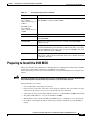
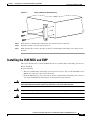
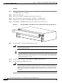
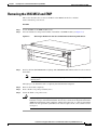
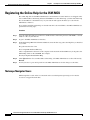
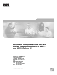
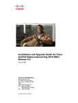
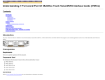
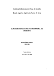
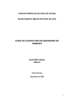
C H A P T E R
2
Installing the Cisco Unified
Videoconferencing 3545 MCU
The Cisco Unified Videoconferencing 3545 MCU works together with a Cisco Unified
Videoconferencing 3545 EMP Enhanced Media Processor (EMP) module to perform audio and
videoconferencing. The Cisco Unified Videoconferencing 3545 MCU is responsible for signaling and
audio. The EMP is responsible for video. The Cisco Unified Videoconferencing 3545 MCU and EMP
modules connect via the Ethernet.
Each Cisco Unified Videoconferencing 3545 MCU may be registered to up to three EMP modules on the
same chassis.
For correct operation, the EMP card must register with the MCU.
This section describes the following topics:
•
Physical Description of the Cisco Unified Videoconferencing 3545 MCU and EMP Modules, page
2-2
•
Preparing to Install the 3545 MCU, page 2-3
•
Verifying the Package Contents of the 3545 MCU, page 2-4
•
Mounting the Cisco Unified Videoconferencing 3545 Chassis in a 19-inch Rack, page 2-4
•
Installing the 3545 MCU and EMP, page 2-5
•
Removing the 3545 MCU and EMP, page 2-7
•
Initial 3545 MCU Configuration, page 2-8
•
Initial 3545 EMP Configuration, page 2-13
•
Accessing the 3545 MCU Administrator Interface, page 2-18
•
Using the 3545 MCU Setup Wizard, page 2-19
•
Registering the Online Help for the 3545 MCU, page 2-20
Installation and Upgrade Guide for Cisco Unified Videoconferencing 3545 MCU Release 5.1
OL-11899-01
2-1
Chapter 2
Physical Description of the Cisco Unified Videoconferencing 3545 MCU and EMP Modules
Installing the Cisco Unified Videoconferencing 3545 MCU
Physical Description of the Cisco Unified
Videoconferencing 3545 MCU and EMP Modules
This section provides a physical description of the Cisco Unified Videoconferencing 3545 MCU and
Cisco Unified Videoconferencing 3545 EMP modules.
Physical Description of the Cisco Unified Videoconferencing 3545 MCU
Module
The Cisco Unified Videoconferencing 3545 MCU module has a 10/100BaseT Ethernet port on the front
panel that uses an RJ-45 connector to connect to the network. There is an asynchronous, 9-pin serial port
that you can use with a hyperterminal program to configure and monitor the module.
Figure 2-1 shows the front panel of the Cisco Unified Videoconferencing 3545 MCU module. Table 2-1
describes the components of the front panel.
Cisco Unified Videoconferencing 3545 MCU Front Panel
GK Reg CPU-Hight
SERIAL
RST
10/100Base T-1
ALARM ACT
157270
Figure 2-1
SWAP
RDY
Physical Description of the Cisco Unified Videoconferencing 3545 EMP
Module
Figure 2-2 shows the front panel of the Cisco Unified Videoconferencing 3545 EMP board. Table 2-1
describes the components of the front panel.
Cisco Unified Videoconferencing 3545 EMP Front Panel
MC
SERIAL
10/100Base T
Table 2-1
RST
CPU-Hight
ALARM ACT
157271
Figure 2-2
SWAP
RDY
Front Panel Components
Component
Description
10/100 BaseT-1
connector
An RJ-45 connector that provides the primary Ethernet connection for the IP
network port.
SERIAL connector
A DB-9 connector that allows you to connect a PC terminal for local
configuration.
RST button
Allows you to reset the board manually.
Installation and Upgrade Guide for Cisco Unified Videoconferencing 3545 MCU Release 5.1
2-2
OL-11899-01
Chapter 2
Installing the Cisco Unified Videoconferencing 3545 MCU
Preparing to Install the 3545 MCU
Table 2-1
Front Panel Components (continued)
Component
Description
GK Reg LED (on the
Cisco Unified
Videoconferencing 354
5 MCU)
Lights green when the MCU is registered with a gatekeeper. Lights green
when the EMP is registered with the MCU.
MC LED (on the
Cisco Unified
Videoconferencing 354
5 EMP)
CPU High LED
Lights green when more than 50% of the MCU/EMP resources are in use.
ACT LED
Lights green to indicate that there is at least one currently active conference
on the MCU/EMP.
ALARM LED
Lights green to indicate that an error has occurred and the MCU/EMP
requires resetting.
10/100 BaseT-1 LEDs
The top part of the 10/100 BaseT-1 connector contains two LED indicators.
The left-hand LED lights green when the local IP network link is active. The
right-hand LED lights green if the connection speed is 100 Mbps, and is off
when the connection speed is 10 Mbps.
SWAP RDY LED
Hot Swap indication. Lights blue when the latches of a board are unlocked
and it is safe to remove the board from the chassis. Goes off when the board
is completely detached.
Preparing to Install the 3545 MCU
This section describes the requirements for installing the Cisco Unified Videoconferencing 3545 MCU
and the Cisco Unified Videoconferencing 3545 EMP in a Cisco Unified
Videoconferencing 3545 chassis. For more information, see the Platform Guide for Cisco IPVC 3644
Chassis.
Warning
During this procedure, wear grounding wrist straps to avoid ESD damage to the card. Do not directly
touch the backplane with your hand or any metal tool, or you could shock yourself.
The requirements are as follows:
•
Cisco Unified Videoconferencing 3545 chassis
•
Proper clearance at the sides of the unit to allow adequate ventilation, and at least 20 cm clearance
at the back of the chassis to allow access to the boards and cable connections
•
A PC with a serial port and terminal emulation software to assign the MCU and EMP an IP address
•
Two dedicated IP addresses—one each for the MCU and EMP
•
The IP address of the router that the MCU and EMP will use to communicate across the network
•
For an H.323 environment, IP address of the H.323 gatekeeper with which you want the MCU to
register
Installation and Upgrade Guide for Cisco Unified Videoconferencing 3545 MCU Release 5.1
OL-11899-01
2-3
Chapter 2
Installing the Cisco Unified Videoconferencing 3545 MCU
Verifying the Package Contents of the 3545 MCU
•
For a Skinny Client Control Protocol (SCCP) environment, the IP address of the Trivial File Transfer
Protocol (TFTP) server or Cisco Unified CallManager from which you want the MCU and EMP to
get configuration information
•
Available IP network ports on the switch for the MCU and EMP
•
A grounded AC power outlet
•
A 10BaseT or 100BaseT LAN cable
•
Ambient room temperature range of 32o to 122oF (0o to 50oC)
•
Non-condensing relative humidity range of 5% to 85%
Verifying the Package Contents of the 3545 MCU
Inspect the contents of the box for shipping damage. Report any damage or missing items to your Cisco
representative. Table 2-2 lists the package contents for the MCU and EMP.
Table 2-2
Package Contents with Cisco Unified Videoconferencing 3545 MCU and Cisco Unified
Videoconferencing 3545 EMP
Product
Cisco Unified
Videoconferencing
3545 chassis with
MCU and EMP
Contents
•
Cisco Unified Videoconferencing 3545 MCU module
•
Cisco Unified Videoconferencing 3545 EMP module
•
Guide to Cisco Conferencing Documentation
•
Regulatory Compliance and Safety Information for Cisco Unified
Videoconferencing 3500 Products
•
Cisco Unified Videoconferencing Software CD-ROM
•
Cisco Information Package
Mounting the Cisco Unified Videoconferencing 3545 Chassis in
a 19-inch Rack
You can optionally mount the Cisco Unified Videoconferencing 3545 chassis in a standard 19-inch rack.
Two mounting brackets and a set of screws are included in the Cisco Unified
Videoconferencing 3545 chassis shipping box.
Procedure
Step 1
Disconnect all cables including the power cables.
Step 2
Place the Cisco Unified Videoconferencing 3545 chassis right-side up on a hard flat surface, with the
front panel facing you.
Step 3
Position a mounting bracket over the mounting holes on each side of the Cisco Unified
Videoconferencing 3545 chassis, as shown in Figure 2-3.
Step 4
Pass the screws through the brackets and tighten them into the screw holes on each side of the
Cisco Unified Videoconferencing 3545 chassis using a suitable screwdriver.
Installation and Upgrade Guide for Cisco Unified Videoconferencing 3545 MCU Release 5.1
2-4
OL-11899-01
Chapter 2
Installing the Cisco Unified Videoconferencing 3545 MCU
Installing the 3545 MCU and EMP
Fitting a Bracket for Rack Mounting
157267
Figure 2-3
Step 5
Insert the Cisco Unified Videoconferencing 3545 chassis into the 19-inch rack.
Step 6
Fasten the brackets to the side rails of the rack.
Step 7
Make sure that the air vents at the sides of the Cisco Unified Videoconferencing 3545 chassis are not
blocked.
Installing the 3545 MCU and EMP
This section describes how to insert the MCU into the Cisco Unified Videoconferencing 3545 chassis.
Before You Begin
Note the following:
•
The Cisco Unified Videoconferencing 3545 chassis has four slots. You can install the MCU and the
EMP in any of the slots at the front of the chassis.
•
Insert the MCU in the top slot at the front of the Cisco Unified Videoconferencing 3545 chassis to
view status and identification information via the System web user interface.
Warning
During this procedure, wear grounding wrist straps to avoid ESD damage to the card. Do not directly
touch the backplane with your hand or any metal tool, or you could shock yourself.
Warning
Only trained and qualified personnel should be allowed to install, replace, or service this equipment.
Warning
Before working on a system that has an on/off switch, turn OFF the power and unplug the power cord.
Installation and Upgrade Guide for Cisco Unified Videoconferencing 3545 MCU Release 5.1
OL-11899-01
2-5
Chapter 2
Installing the Cisco Unified Videoconferencing 3545 MCU
Installing the 3545 MCU and EMP
Procedure
Step 1
On the front of the chassis, loosen the screws of the blank panel covering the slot into which the MCU
or the EMP module is to be installed.
Step 2
Remove the blank panel.
Step 3
Remove the new MCU or the EMP module from the antistatic bag.
Step 4
Press the red buttons and open the handles of the MCU or the EMP module.
Step 5
Align the edges of the MCU or the EMP module with the chassis guide rails.
Step 6
Slide the MCU or the EMP module into the chassis until it stops (see Figure 2-4).
Inserting the MCU or the EMP in the Cisco Unified Videoconferencing 3545 Chassis
157274
Figure 2-4
Step 7
Use even pressure to push the module further into the slot.
Caution
Note
Do not force the connection. Forcing the connection can bend or damage the pins in the
connector inside the chassis.
If you are installing the MCU or the EMP module and the power to the chassis is on, the
SWAP RDY LED on the module front panel turns blue when you slide the module into the
chassis as far as it will go. This means that you can secure the module safely. The LED turns
off when the handles are closed.
Step 8
Snap the handles forward to secure the MCU or the EMP module in the slot.
Step 9
Secure the MCU or the EMP module screws.
Caution
Blank faceplates and cover panels serve three important functions: they prevent exposure to
hazardous voltages and currents inside the chassis; they contain electromagnetic interference
(EMI) that might disrupt other equipment; and they direct the flow of cooling air through the
chassis. Do not operate the system unless all cards, faceplates, front covers and rear covers
are in place.
Installation and Upgrade Guide for Cisco Unified Videoconferencing 3545 MCU Release 5.1
2-6
OL-11899-01
Chapter 2
Installing the Cisco Unified Videoconferencing 3545 MCU
Removing the 3545 MCU and EMP
Removing the 3545 MCU and EMP
This section describes how to remove the MCU or the EMP from the Cisco Unified
Videoconferencing 3545 chassis.
Procedure
Step 1
Loosen the MCU or the EMP module screws.
Step 2
Press the red buttons and open the handles of the MCU or the EMP module (see Figure 2-5).
Removing a Module from the Cisco Unified Videoconferencing 3545 Chassis
157279
Figure 2-5
Step 3
Wait for the blue SWAP RDY LED to light up. The SWAP RDY LED indicates that it is safe to remove
the module.
Note
It may take up to one minute for the LED to light up while the Windows operating system is
shutting down.
The light goes out when the board is completely detached from the backplane.
Step 4
Remove the module completely.
Step 5
Insert a blank cover panel provided by Cisco.
Step 6
Secure the blank cover panel screws.
Caution
Blank faceplates and cover panels serve three important functions: they prevent exposure to
hazardous voltages and currents inside the chassis; they contain electromagnetic interference
(EMI) that might disrupt other equipment; and they direct the flow of cooling air through the
chassis. Do not operate the system unless all cards, faceplates, front covers, and rear covers
are in place.
Installation and Upgrade Guide for Cisco Unified Videoconferencing 3545 MCU Release 5.1
OL-11899-01
2-7
Chapter 2
Installing the Cisco Unified Videoconferencing 3545 MCU
Initial 3545 MCU Configuration
Initial 3545 MCU Configuration
Initial monitoring and administration of the Cisco Unified Videoconferencing 3545 MCU are performed
from a remote PC via a serial connection. This allows you to access the boot configuration menu of the
MCU. At power-up, the MCU goes through the following boot phases:
Note
•
Auto-boot—The embedded operating system initializes and displays basic information.
•
Configuration menu—A six-second countdown allows you to enter the configuration menu.
•
Initialization—The MCU completes its boot sequence and is ready for operation.
You can perform serial port configuration of the MCU only at startup, during a short period indicated by
a six-second countdown. Once the initialization phase is complete, the only way you can access the
configuration menu is by restarting the MCU.
Connecting to a PC
This section describes how to use the serial port connection to configure the MCU with an IP address.
Procedure
Step 1
Locate the terminal cable shipped with the MCU.
Step 2
Connect the end labeled PC to the serial port on the computer.
Step 3
Connect the end labeled Unit to the serial port connector on the MCU front panel.
Note
The PC terminal should have an installed terminal emulation application, such as HyperTerminal.
Setting the IP Address
This section describes how to use the serial port to configure the unit with an IP address and other
address information.
The serial port on the MCU front panel is used to assign a new IP address to your MCU. You can assign
the IP address before or after you connect the MCU to the network.
Before You Begin
Gather the items listed in Table 2-3 to assign an IP address to the MCU.
Table 2-3
Requirements for Setting the IP Address
Requirements
Notes
Dedicated IP address for the MCU
IP address of the default router the MCU uses to
communicate over the network
Installation and Upgrade Guide for Cisco Unified Videoconferencing 3545 MCU Release 5.1
2-8
OL-11899-01
Chapter 2
Installing the Cisco Unified Videoconferencing 3545 MCU
Initial 3545 MCU Configuration
Table 2-3
Requirements for Setting the IP Address
Requirements
Notes
Subnet mask for the MCU if applicable
Domain Name Server and domain name for MCU
if applicable
PC with available serial port and terminal
emulator software installed
RS-232 terminal cable (shipped with the unit)
Procedure
Step 1
Connect the RS-232 terminal cable to the PC terminal.
Step 2
Connect the power cable.
Step 3
Start the terminal emulation application on the PC.
Step 4
Set the communication settings in the terminal emulation application on the PC as follows:
– Baud rate: 9600
– Data bits: 8
– Parity: None
– Stop bits: 1
– Flow control: None
Step 5
Turn on the power to the MCU.
A log of the auto-boot events appears on the computer.
Step 6
When the message “Press any key to start configuration” appears on the screen, press any key within six
seconds.
The network configuration Main menu appears as follows:
Press any key to start configuration...
Main menu
N: Configure default network port values
P: Change the configuration software password
S: Configure network security level
A: Advanced configuration menu
Q: Quit
Select:
Step 7
At the prompt, enter N to configure default network port values and press Enter.
Step 8
At the Enter IP address for default interface prompt, enter the IP address you want to assign to the MCU
and press Enter.
Caution
Step 9
Do not use leading zeros in the IP address.
At the Enter Default Router IP Address prompt, enter the IP address of the router associated with the
segment in which the unit will be installed and press Enter.
Installation and Upgrade Guide for Cisco Unified Videoconferencing 3545 MCU Release 5.1
OL-11899-01
2-9
Chapter 2
Installing the Cisco Unified Videoconferencing 3545 MCU
Initial 3545 MCU Configuration
Do not use leading zeros in the IP address.
Caution
Step 10
At the Enter IP Mask <HEX> for default device prompt, enter the subnet mask as follows:
– Convert the subnet mask IP address to hexadecimal notation, enter the hexadecimal number at
the prompt, and press Enter.
For example, for the subnet mask 255.255.255.0 the hexadecimal value you enter is FFFFFF00.
Note
You can use the desktop calculator on your computer to convert the subnet mask ID to
hexadecimal notation.
– If a subnet mask is not used, press Enter.
After you enter the subnet mask parameter, the unit updates the boot line parameter and reboots.
Step 11
At the Enter Preferred DNS Address for default Interface prompt, enter the IP address of the primary
DNS to which you want this MCU to register and press Enter.
Step 12
At the Enter Alternate DNS Address for default Interface prompt, enter the IP address of the secondary
DNS to which you want this MCU to register and press Enter.
Step 13
At the Enter DNS suffix for default Interface prompt, enter the alias to which you want the DNS to
associate this MCU and press Enter.
Allow the unit to complete the reboot process. A new emulator session begins.
Step 14
At the Network Configuration menu, do one of the following:
– Enter the letter for the set of parameters that you want to configure.
– Enter Q to save your changes and allow the device to complete the boot process.
Caution
Configuration of any of the parameters other than <N> to configure default network port values may alter
the function of the device and should not be performed by an unauthorized person.
Setting Ethernet Speed and Duplex Parameters
You can use the serial port to set the Ethernet speed and duplex parameters that you want the MCU to use.
Note
We recommend that you manually set these parameters on the MCU and switch to Ethernet speed 100
Mbps and full duplex.
Procedure
Step 1
Access the MCU through the serial port and start a terminal emulator session.
Note
If the MCU is already running, you need to reboot or restart the device.
Installation and Upgrade Guide for Cisco Unified Videoconferencing 3545 MCU Release 5.1
2-10
OL-11899-01
Chapter 2
Installing the Cisco Unified Videoconferencing 3545 MCU
Initial 3545 MCU Configuration
Step 2
When the message “Press any key to start configuration” appears on the screen, press any key within six
seconds.
The network configuration Main menu appears.
Step 3
At the prompt, enter A to display the Advanced Configuration menu and press Enter.
The Advanced Configuration menu appears.
Step 4
At the prompt, enter 3 to select “Change LAN port Settings” and press Enter.
Step 5
At the prompt, enter the number or letter for one of the following:
– 1 - 10Mbps Half Duplex
– 2 - 100Mbps half Duplex
– 3 - 10Mbps Full Duplex
– 4 - 100Mbps Full Duplex
– 5 - Auto
– Q - Quit
Enter this value to retain the current setting. The default setting is Auto.
Step 6
Press Enter.
The network configuration Main menu appears.
Step 7
At the Network Configuration menu, do one of the following:
– Enter the letter for the set of parameters that you want to configure.
– Enter Q to save your changes and allow the device to complete the boot process.
Setting a TFTP Server
You can use the Cisco Unified Videoconferencing 3545 MCU together with the Cisco Unified
Videoconferencing 3545 EMP as a video conference bridge for Cisco Unified CallManager version 4.x
and later. To set up the Cisco Unified Videoconferencing 3545 MCU to serve as a conference bridge, you
must identify the TFTP server from which the Cisco Unified Videoconferencing 3545 MCU gets
configuration information from the Cisco Unified CallManager. You can enter that information using the
serial port connection or the Administrator interface.
Procedure
Step 1
Access the MCU through the serial port and start a terminal emulator session.
Note
Step 2
If the MCU is already running, you need to reboot or restart the device.
When the message “Press any key to start configuration” appears on the screen, press any key within six
seconds.
The Network Configuration menu appears.
Step 3
At the prompt, enter T and press the Enter key to select the “Configure TFTP server list” option.
Installation and Upgrade Guide for Cisco Unified Videoconferencing 3545 MCU Release 5.1
OL-11899-01
2-11
Chapter 2
Installing the Cisco Unified Videoconferencing 3545 MCU
Initial 3545 MCU Configuration
Step 4
At the TFTP Server # 0 prompt, enter the IP address of the first TFTP server you want the MCU to use
and press Enter.
Step 5
At the Would you like to add a new TFTP server [Y/N] prompt, do one of the following:
– Press Y and enter to identify another TFTP server that you want the MCU to use.
– Press N and Enter to return to the Network Configuration menu.
Step 6
At the Network Configuration menu, do one of the following:
– Enter the letter for the set of parameters that you want to configure.
– Enter Q to save your changes and allow the device to complete the boot process.
This information appears in the SCCP Protocol Configuration dialog box in the Administrator interface.
In this dialog box, you can configure the MCU to support Cisco Unified CallManager as a SCCP
conference bridge
Changing the Global User Name and Password
You can change the global user name and password that the MCU uses. You use this user name and
password to access the configuration web page for the MCU, and is required for the following tasks:
•
Starting a Telnet session to monitor the MCU
•
Upgrading the MCU software
•
Uploading Interactive Voice Response (IVR) messages to MCU configuration memory
The default global user name is admin. The default password is <null>.
Procedure
Step 1
Start a terminal emulator session as described in the “Setting the IP Address” section on page 2-8.
Step 2
At the prompt, enter P.
Step 3
At the Enter User name prompt, enter the name that you want to use as the global user name and press
Enter.
Step 4
At the Password prompt, enter the password that you want to use and press Enter.
The network configuration Main menu appears.
Step 5
At the network configuration Main menu, do one of the following:
– Enter the letter for the set of parameters that you want to configure.
– Enter Q to save your changes and allow the device to complete the boot process.
Installation and Upgrade Guide for Cisco Unified Videoconferencing 3545 MCU Release 5.1
2-12
OL-11899-01
Chapter 2
Installing the Cisco Unified Videoconferencing 3545 MCU
Initial 3545 EMP Configuration
Connecting the Cisco Unified Videoconferencing 3545 MCU to the LAN
This section describes how to connect the MCU to the Local Area Network (LAN).
Procedure
Step 1
Connect the supplied LAN cable from your network switch to the 10/100BaseT Ethernet port on the front
panel of the MCU unit. The 10/100BaseT port accepts an RJ-45 connector.
Step 2
Turn on the power to the MCU unit.
Upgrading Cisco Unified Videoconferencing 3545 MCU Software
You can perform software upgrades by using the Cisco Upgrade Utility to upload files via a network or
modem connection to the MCU. For more information, see Chapter 3, “Using the Cisco Software
Upgrade Utility”.
Initial 3545 EMP Configuration
When you are working with a Cisco Unified Videoconferencing 3545 EMP, you must also perform
network configuration of this module.
Initial monitoring and administration of the EMP are performed from a remote PC using a terminal
emulation application, such as HyperTerminal. To make the serial connection, connect a PC terminal to
the front panel serial port of the EMP board as described in the “Connecting to a PC” section on
page 2-8. The serial configuration utility runs as a target configuration service. You can use the serial
configuration utility to:
Warning
•
Configure default network port values.
•
Modify the configuration software password.
•
Modify the MCU IP address.
•
Modify advanced configuration settings such as the web server port and LAN port, and to restore
the factory configuration.
To enable the EMP to function properly, you must configure the EMP with a different IP address to your
MCU.
Accessing the Cisco Unified Videoconferencing 3545 EMP Main Menu
You access the EMP Main configuration menu in the same way as you access the MCU network
configuration Main menu as described in the “Procedure” section on page 2-9.
The EMP Main configuration menu appears as follows:
Main menu
N: Configure default network port values
P: Change the configuration software password
Installation and Upgrade Guide for Cisco Unified Videoconferencing 3545 MCU Release 5.1
OL-11899-01
2-13
Chapter 2
Installing the Cisco Unified Videoconferencing 3545 MCU
Initial 3545 EMP Configuration
S:
M:
A:
Q:
Configure network security level
Change MCU ip address
Advanced configuration menu
Quit
Select:
Setting the IP Address
This section describes how to use the serial port to configure the unit with an IP address and other
address information.
The serial port on the EMP front panel is used to assign a new EMP an IP address. You can assign the
IP address before or after you connect the hardware to the network.
Procedure
Step 1
At the prompt, enter N to configure default network port values and press Enter.
The default network properties screen appears as follows:
Enter IP Address for default Interface
Without leading zeros <172.20.35.110:ffff0000>
Enter Default Router IP Address for default Interface
Without leading zeros <current default Gateway IP address>:
Step 2
At the Enter IP address for default interface prompt, enter the IP address you want to assign to the EMP
followed by the subnet mask, in the format <IP address:subnet mask> and press Enter.
Note
Step 3
You must enter the subnet mask in the hexadecimal format.
At the Enter Default Router IP Address prompt, enter the IP address of the default Gateway that you
want the EMP to use and press Enter.
Allow the unit to complete the reboot process. A new emulator session begins.
Step 4
At the Main menu, do one of the following:
– Enter the letter for the set of parameters that you want to configure.
– Enter Q to save your changes and allow the device to complete the boot process.
Caution
Configuration of any of the parameters other than <N> to configure default network port values may alter
the function of the device and should not be performed by an unauthorized person.
Installation and Upgrade Guide for Cisco Unified Videoconferencing 3545 MCU Release 5.1
2-14
OL-11899-01
Chapter 2
Installing the Cisco Unified Videoconferencing 3545 MCU
Initial 3545 EMP Configuration
Changing the Configuration Software Password
You can use the serial port to change the configuration software password.
Procedure
Step 1
At the prompt, enter P to change the configuration software password and press Enter.
The user profile screen displays as follows:
Enter user name:
Enter new password:
Step 2
At the Enter user name prompt, enter the new user name and press Enter.
Step 3
At the Enter user password prompt, enter the new password and press any key to return to the EMP Main
menu.
Changing the Security Level
You can use the serial port to change the security level. Security levels are as follows:
•
0 (low)—Allows SNMP, Telnet, HTTP, FTP, and ICMP to access the MCU.
•
1 (medium)—Allows access to the MCU only through SNMP, HTTP and ICMP.
•
2 (high)—Allows only HTTP to access the MCU.
Procedure
Step 1
At the prompt, enter S to configure the network security level and press Enter.
The security level screen displays as follows:
The current security level is [0 low].
Enter a new security level (0-low, 1-medium. 2-high):
Step 2
Enter the new security level required and press Enter.
The updated security level screen displays as follows:
The current security level is [0 low].
Enter a new security level (0-low, 1-medium. 2-high):
2
Board security level changing to [2 high]:
Set icmpRequestBlock to 2
The new security level is [2 high].
Step 3
The EMP Main menu displays.
Installation and Upgrade Guide for Cisco Unified Videoconferencing 3545 MCU Release 5.1
OL-11899-01
2-15
Chapter 2
Installing the Cisco Unified Videoconferencing 3545 MCU
Initial 3545 EMP Configuration
Pointing the EMP to the Controlling MCU
You can use the serial port to point the EMP to the IP address of the controlling MCU.
Procedure
Step 1
At the prompt, enter M to change the MCU IP address and press Enter.
The MCU IP address screen displays as follows:
Enter MCU ip address
Without leading zeros <current IP address>:
Step 2
Enter the IP address of the MCU and press any key to return to the EMP Main menu.
Changing Advanced Configuration Settings
You can use the serial port to change the following advanced configuration settings:
•
Web server port (for future use)
•
Restore factory configuration (for future use)
•
LAN port settings
•
Disable DSP reset
Procedure
Step 1
At the prompt, enter A to access the Advanced Configuration menu.
The Advanced Configuration menu displays as follows:
Advanced configuration menu
Q: Quit
1: Configure web server port
2: Restore factory configuration
3: Change Lan port Settings
4: Disable DSP reset
Select:
Step 2
At the prompt, enter 1 to configure the web server port.
The current web port server setting displays.
Step 3
At the prompt, enter 2 to restore the factory configuration settings.
You are asked to confirm your choice as follows:
Select: 2
Are you sure you want to restore factory configuration? [y, n]:
Step 4
Enter y or n.
Step 5
At the prompt, enter 3 to change Ethernet speed and duplex parameters.
The network interface card settings screen appears as follows:
Choose :
:
:
:
1
2
3
4
-
10Mbps
100Mbps
10Mbps
100Mbps
Half
Half
Full
Full
Duplex
Duplex
Duplex
Duplex
Installation and Upgrade Guide for Cisco Unified Videoconferencing 3545 MCU Release 5.1
2-16
OL-11899-01
Chapter 2
Installing the Cisco Unified Videoconferencing 3545 MCU
Initial 3545 EMP Configuration
: 5 - Auto
other - Quit
:
Step 6
Enter either a number between 0 and 5 inclusive, representing the required option.
Step 7
Press any other key to quit without changing the network working mode.
Step 8
At the prompt, enter 4 to disable the DSP reset facility.
Note
Caution
After options Q and 1-3, press any key to return to the EMP Main menu. After option 4, the EMP Main
menu displays automatically.
Only qualified technical personnel should modify the DSP reset function settings.
Saving Network Configuration Settings
Modified network configuration settings are automatically saved when you exit the EMP Main menu.
Procedure
Step 1
Ensure you have completed your configuration.
Step 2
At the prompt, enter Q to exit the video processing module Main menu.
The video processing module Main menu closes and your machine will automatically reboot.
Connecting the EMP to the LAN
This section describes how to connect the EMP to the Local Area Network (LAN).
Procedure
Step 1
Connect the supplied LAN cable from your network switch to the 10/100BaseT Ethernet port on the front
panel of the EMP unit. The 10/100BaseT port accepts an RJ-45 connector.
Step 2
Turn on the power to the EMP unit.
Installation and Upgrade Guide for Cisco Unified Videoconferencing 3545 MCU Release 5.1
OL-11899-01
2-17
Chapter 2
Installing the Cisco Unified Videoconferencing 3545 MCU
Accessing the 3545 MCU Administrator Interface
Accessing the 3545 MCU Administrator Interface
The Cisco Unified Videoconferencing 3545 MCU Administrator is a web interface that allows you to
configure general MCU settings, monitor MCU operation, create or edit services, manage media
processor units and perform maintenance.
You access the MCU Administrator web interface in the MCU access window by signing in as an
Administrator.
You can use your web browser from any remote PC station to monitor and to configure the MCU
application. A web server is installed in the MCU to facilitate the use of the remote web-based
monitoring and management.
Access to the MCU configuration interface is controlled by a user name and a password. Once you have
entered the settings you want, you should upload them to the unit for them to take effect, or you can save
them to a configuration file to be loaded at a later time.
Before You Begin
The following requirements are necessary to access the MCU Administrator web interface:
Note
•
A Java-compliant browser. Microsoft Internet Explorer version 5.5 or later is recommended.
•
The MCU IP address or a web link to the MCU.
•
The required user name and password.
For first-time installation, you must assign an IP address to the MCU using a serial port connection
before you can access the web interface. For more information, see the “Setting the IP Address” section
on page 2-8.
Procedure
Step 1
Launch your browser and enter the IP address or the name of the MCU followed by /admin.
For example, http://125.221.23.44/admin or board_name/admin.
The MCU access window appears.
Step 2
Enter the Administrator user name and password in the appropriate fields and click Go. The default
global user name is admin. The default password is <null>.
The MCU Administrator interface appears.
Note
If you try to sign in as an Administrator and another Administrator is currently signed in, the MCU signs
you in as a Read only user. The words Read Only appear at the top of the window and a pop-up displays
the IP address of the Administrator already signed in. Read only users cannot edit any of the MCU
settings.
Installation and Upgrade Guide for Cisco Unified Videoconferencing 3545 MCU Release 5.1
2-18
OL-11899-01
Chapter 2
Installing the Cisco Unified Videoconferencing 3545 MCU
Using the 3545 MCU Setup Wizard
Using the 3545 MCU Setup Wizard
The MCU setup wizard runs automatically the first time you access the MCU Administrator interface.
In the setup wizard, you can configure addressing for the MCU IP, H.323 gatekeeper, and Session
Initiation Protocol (SIP) proxy. In the setup wizard, you can also set the regional date and time settings
of the device on which you manage the MCU.
Procedure
Step 1
In the Administrator interface, click MCU
Step 2
On the toolbar, click Setup Wizard.
The MCU Setup Wizard dialog box appears, displaying the Board Settings section.
Step 3
To change the IP address information with which the MCU is currently configured, follow these steps:
– In the IP address field, enter the IP address you want to assign to the MCU.
– In the Subnet mask field, enter the subnet mask you want to assign to the MCU.
– In the Router IP address field, enter the IP address of the router that you want the MCU to use.
– Click Next.
The H.323 Settings section appears.
Step 4
To set the gatekeeper you want the MCU to use, follow these steps:
– In the Gatekeeper IP field, enter the IP address of the gatekeeper that you want the MCU to use.
– In the Gatekeeper Port field, enter the port number that the MCU can use to communicate with
the gatekeeper.
– Click Next.
The SIP Settings section appears.
Step 5
To change SIP configuration, follow these steps:
– In the Proxy IP field, enter the IP address for the SIP proxy.
– In the Proxy Port field, enter the port for the SIP proxy.
– In the Default Domain field, enter the default domain for the SIP proxy.
– Select Using Microsoft LCS if the SIP proxy communicates with a Microsoft Live
Communication Server device.
The Date and Time Settings section appears.
Step 6
To synchronize the MCU clock with the clock on the current computer, select Update to local time.
Step 7
Click Finish.
Installation and Upgrade Guide for Cisco Unified Videoconferencing 3545 MCU Release 5.1
OL-11899-01
2-19
Chapter 2
Installing the Cisco Unified Videoconferencing 3545 MCU
Registering the Online Help for the 3545 MCU
Registering the Online Help for the 3545 MCU
The online help files for the MCU Administrator and Conference Control interfaces are shipped on the
Cisco Unified Videoconferencing Software CD-ROM. To use the online help, you must install the help
files for the MCU in a shared directory on your network and register the directory location in the
Administrator interface.
If you wish to install the online help on a shared network location and link it to the MCU Administrator,
perform the following steps:
Procedure
Step 1
Copy the online help library from the Cisco Unified Videoconferencing Software CD-ROM to a shared
folder on a PC on your network.
Step 2
Log in to the MCU Administrator interface.
Step 3
In the Online help URL field of the Board Web tab, enter the directory path to the help files you installed
on your PC.
The path must have the form:
file://computerName/sharedDirectory
where computerName is the name of the computer on the network and sharedDirectory is the path to the
Online Help folder on the CD-ROM. For example:
file://myComputer/Shared/Online Help
Step 4
Click Upload in the Cisco Unified Videoconferencing 3545 MCU Administrator toolbar, followed by
Refresh.
Step 5
You may need to log out and log back in to the MCU Administrator for the change to take effect.
Netscape Navigator Users
Online help files located on the local network and accessed using Netscape Navigator 4.x must be
located on a mapped network drive.
Installation and Upgrade Guide for Cisco Unified Videoconferencing 3545 MCU Release 5.1
2-20
OL-11899-01