1
Cisco 3200 Series Router Hardware
Reference
August 2008
Americas Headquarters
Cisco Systems, Inc.
170 West Tasman Drive
San Jose, CA 95134-1706
USA
http://www.cisco.com
Tel: 408 526-4000
800 553-NETS (6387)
Fax: 408 527-0883
Text Part Number: OL-5816-10
THE SPECIFICATIONS AND INFORMATION REGARDING THE PRODUCTS IN THIS MANUAL ARE SUBJECT TO CHANGE WITHOUT NOTICE. ALL
STATEMENTS, INFORMATION, AND RECOMMENDATIONS IN THIS MANUAL ARE BELIEVED TO BE ACCURATE BUT ARE PRESENTED WITHOUT
WARRANTY OF ANY KIND, EXPRESS OR IMPLIED. USERS MUST TAKE FULL RESPONSIBILITY FOR THEIR APPLICATION OF ANY PRODUCTS.
THE SOFTWARE LICENSE AND LIMITED WARRANTY FOR THE ACCOMPANYING PRODUCT ARE SET FORTH IN THE INFORMATION PACKET THAT
SHIPPED WITH THE PRODUCT AND ARE INCORPORATED HEREIN BY THIS REFERENCE. IF YOU ARE UNABLE TO LOCATE THE SOFTWARE LICENSE
OR LIMITED WARRANTY, CONTACT YOUR CISCO REPRESENTATIVE FOR A COPY.
The following information is for FCC compliance of Class A devices: This equipment has been tested and found to comply with the limits for a Class A digital device, pursuant
to part 15 of the FCC rules. These limits are designed to provide reasonable protection against harmful interference when the equipment is operated in a commercial
environment. This equipment generates, uses, and can radiate radio-frequency energy and, if not installed and used in accordance with the instruction manual, may cause
harmful interference to radio communications. Operation of this equipment in a residential area is likely to cause harmful interference, in which case users will be required
to correct the interference at their own expense.
The following information is for FCC compliance of Class B devices: The equipment described in this manual generates and may radiate radio-frequency energy. If it is not
installed in accordance with Cisco’s installation instructions, it may cause interference with radio and television reception. This equipment has been tested and found to
comply with the limits for a Class B digital device in accordance with the specifications in part 15 of the FCC rules. These specifications are designed to provide reasonable
protection against such interference in a residential installation. However, there is no guarantee that interference will not occur in a particular installation.
Modifying the equipment without Cisco’s written authorization may result in the equipment no longer complying with FCC requirements for Class A or Class B digital
devices. In that event, your right to use the equipment may be limited by FCC regulations, and you may be required to correct any interference to radio or television
communications at your own expense.
You can determine whether your equipment is causing interference by turning it off. If the interference stops, it was probably caused by the Cisco equipment or one of its
peripheral devices. If the equipment causes interference to radio or television reception, try to correct the interference by using one or more of the following measures:
• Turn the television or radio antenna until the interference stops.
• Move the equipment to one side or the other of the television or radio.
• Move the equipment farther away from the television or radio.
• Plug the equipment into an outlet that is on a different circuit from the television or radio. (That is, make certain the equipment and the television or radio are on circuits
controlled by different circuit breakers or fuses.)
Modifications to this product not authorized by Cisco Systems, Inc. could void the FCC approval and negate your authority to operate the product.
The Cisco implementation of TCP header compression is an adaptation of a program developed by the University of California, Berkeley (UCB) as part of UCB’s public
domain version of the UNIX operating system. All rights reserved. Copyright © 1981, Regents of the University of California.
NOTWITHSTANDING ANY OTHER WARRANTY HEREIN, ALL DOCUMENT FILES AND SOFTWARE OF THESE SUPPLIERS ARE PROVIDED “AS IS” WITH
ALL FAULTS. CISCO AND THE ABOVE-NAMED SUPPLIERS DISCLAIM ALL WARRANTIES, EXPRESSED OR IMPLIED, INCLUDING, WITHOUT
LIMITATION, THOSE OF MERCHANTABILITY, FITNESS FOR A PARTICULAR PURPOSE AND NONINFRINGEMENT OR ARISING FROM A COURSE OF
DEALING, USAGE, OR TRADE PRACTICE.
IN NO EVENT SHALL CISCO OR ITS SUPPLIERS BE LIABLE FOR ANY INDIRECT, SPECIAL, CONSEQUENTIAL, OR INCIDENTAL DAMAGES, INCLUDING,
WITHOUT LIMITATION, LOST PROFITS OR LOSS OR DAMAGE TO DATA ARISING OUT OF THE USE OR INABILITY TO USE THIS MANUAL, EVEN IF CISCO
OR ITS SUPPLIERS HAVE BEEN ADVISED OF THE POSSIBILITY OF SUCH DAMAGES.
CCDE, CCENT, Cisco Eos, Cisco Lumin, Cisco Nexus, Cisco StadiumVision, Cisco TelePresence, the Cisco logo, DCE, and Welcome to the Human Network are
trademarks; Changing the Way We Work, Live, Play, and Learn and Cisco Store are service marks; and Access Registrar, Aironet, AsyncOS, Bringing the Meeting To You,
Catalyst, CCDA, CCDP, CCIE, CCIP, CCNA, CCNP, CCSP, CCVP, Cisco, the Cisco Certified Internetwork Expert logo, Cisco IOS, Cisco Press, Cisco Systems,
Cisco Systems Capital, the Cisco Systems logo, Cisco Unity, Collaboration Without Limitation, EtherFast, EtherSwitch, Event Center, Fast Step, Follow Me Browsing,
FormShare, GigaDrive, HomeLink, Internet Quotient, IOS, iPhone, iQ Expertise, the iQ logo, iQ Net Readiness Scorecard, iQuick Study, IronPort, the IronPort logo,
LightStream, Linksys, MediaTone, MeetingPlace, MeetingPlace Chime Sound, MGX, Networkers, Networking Academy, Network Registrar, PCNow, PIX, PowerPanels,
ProConnect, ScriptShare, SenderBase, SMARTnet, Spectrum Expert, StackWise, The Fastest Way to Increase Your Internet Quotient, TransPath, WebEx, and the
WebEx logo are registered trademarks of Cisco Systems, Inc. and/or its affiliates in the United States and certain other countries.
All other trademarks mentioned in this document or Website are the property of their respective owners. The use of the word partner does not imply a partnership relationship
between Cisco and any other company. (0807R)
Any Internet Protocol (IP) addresses used in this document are not intended to be actual addresses. Any examples, command display output, and figures included in the
document are shown for illustrative purposes only. Any use of actual IP addresses in illustrative content is unintentional and coincidental.
Cisco 3200 Series Router Hardware Reference
© 2008 Cisco Systems, Inc. All rights reserved.
CONTENTS
Introduction to the Cisco 3200 Series Routers
Audience and Scope
viii
Related Documentation
Conventions
CHAPTER
1
vii
viii
ix
Cisco 3200 Rugged Enclosures
1-1
Cisco 3270 Rugged Enclosure 1-3
Cisco 3270 Router Card Stack 1-4
Cisco 3230 Rugged Enclosure 1-5
Cisco 3230 Router Card Stack 1-6
Rugged Enclosure End Caps 1-7
Antenna End Cap 1-7
I/O End Caps for the Cisco 3200 Rugged Enclosures 1-8
End Cap Fast Ethernet and WMIC Console Ports 1-8
Cisco 3270 Router I/O End Cap 1-9
Cisco 3230 Router I/O End Cap 1-12
Protective End Cap Cover
1-13
I/O End Cap Port Signals 1-15
Gigabit Ethernet Signal Limitations 1-15
Fast Ethernet Signals 1-15
Fast Ethernet Port Cabling for the Cisco 3250 and Cisco 3230 Routers
Console Port Signals 1-17
AUX Port Signals 1-17
Cisco 3200 Rugged Enclosure LED Indications 1-18
Cisco 3270 Rugged Enclosure I/O End Cap LED Indications
Cisco 3230 Rugged Enclosure I/O End Cap LED Indications
WMIC Console LEDs 1-19
Thermal Plates
2
1-18
1-19
1-20
Mounting Brackets
CHAPTER
1-16
1-21
Cisco 3270 Rugged Router Card
2-1
Cisco 3270 Rugged Router Card Component Systems
2-2
Cisco 3200 Series Router Hardware Reference
OL-5816-10
3
Contents
Cisco 3270 Rugged Router Card Power Requirements
Power Connections (AUX) 2-4
Hardware Encryption Processor 2-4
Ethernet Port Speed and Duplex Mode 2-6
Cisco 3270 Rugged Router Card Encryption Module
Security Engine Features 2-7
Temperature Sensor
2-7
2-8
Cisco 3270 Rugged Router Card MAC Address Allocation
CHAPTER
3
2-4
Mobile Access Router Card
2-8
3-1
MARC Component Systems 3-2
MARC Power Requirements 3-3
MARC Router Signals 3-3
Fast Ethernet Signals on the MARC 3-3
Console and Auxiliary Signals 3-4
CHAPTER
4
Fast Ethernet Switch Mobile Interface Card
Autonegotiation and Auto-MDI/MDIX
MAC Address Allocation
5
Serial Mobile Interface Card
4-2
4-2
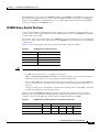
FESMIC Component Systems 4-3
Signals for the FESMIC 4-4
FESMIC Rotary Switch Positions
CHAPTER
4-5
5-1
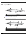
SMIC Component Systems 5-2
Signals for the SMIC 5-3
4-Port SMIC Rotary Switch Positions
2-port SMIC Rotary Switch Positions
SMIC LED Signals 5-4
SMIC Power Consumption
CHAPTER
6
4-1
5-3
5-4
5-5
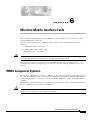
Wireless Mobile Interface Cards
6-1
WMIC Component Systems 6-1
Antenna Connector 6-2
WMIC Console and Fast Ethernet Ports 6-2
Fast Ethernet Signals on the WMIC 6-3
LED Behavior
6-4
Key Features
6-5
Cisco 3200 Series Router Hardware Reference
4
OL-5816-10
Contents
MAC Address Allocation 6-7
WMIC Power Requirement 6-7
Mean Time Between Failure 6-7
Differences Between WMICs 6-7
2.4-GHz (802.11b/g) WMIC Features 6-10
Universal Workgroup Bridge Limitations 6-12
4.9-GHz (Public Safety) WMIC Features 6-13
4.9-GHz Channels 6-13
Throughput 6-14
Modulation 6-14
Receive Sensitivity 6-15
5.0-GHz (802.11h) Radio Features 6-15
5.0-GHz (802.11h) Channels 6-15
Throughput 6-16
Modulation 6-16
Receive Sensitivity 6-16
Transmit Sensitivity 6-17
Related Documentation
6-17
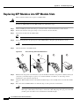
Replacing SFP Modules into SFP Module Slots
Diagnosing SFP Problems B-3
Error Messages B-4
B-2
Cisco 3200 Series Router Hardware Reference
OL-5816-10
5
Contents
Cisco 3200 Series Router Hardware Reference
6
OL-5816-10
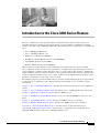
Introduction to the Cisco 3200 Series Routers
The Cisco 3200 Series routers provides industry-standard network software features that run on
ruggedized hardware, suitable for harsh environments. A router includes a combination of mobile
interface cards and a Cisco 3200 Rugged Enclosure. The following major components are available from
Cisco:
•
Cisco 3200 Rugged Enclosures
•
Cisco 3270 Rugged Router card
•
Mobile Access Router Card (MARC)
•
Fast Ethernet Switch Mobile Interface Cards (FESMICs)
•
Serial Mobile Interface Cards (SMICs)
•
Wireless Mobile Interface Cards (WMICs)
This document describes the Cisco cards and the enclosure solutions that are used to assemble
Cisco 3200 Series routers. A router can be purchased as a complete unit or purchased in part from Cisco
and assembled by a qualified system integrator (SI) as a custom solution. For example, a qualified SI
might assemble cards into a custom enclosure to suit a particular environment. Custom solutions based
on Cisco cards must include a power source, cables, and an enclosure. For information about the specific
hardware configuration of your router, contact your SI.
The following chapters provide information that you need for understanding the physical components of
a completed Cisco 3200 Series router. This document is not intended to cover assembly or repair
instructions.
Chapter 1, “Cisco 3270 Rugged Enclosure,” describes the enclosures that house the Cisco 3200 Series
routers.
Chapter 2, “Cisco 3270 Rugged Router Card,” describes the Cisco 3270 Rugged Router card layout.
Chapter 3, “Mobile Access Router Card,” describes the MARC layout.
Chapter 4, “Fast Ethernet Switch Mobile Interface Card,” describes the FESMIC layout, ports, and
buses.
Chapter 5, “Serial Mobile Interface Card,” describes the SMIC layout, ports, and buses.
Chapter 6, “Wireless Mobile Interface Cards,” describes the WMIC layout, ports, and buses.
Appendix A, “Smart Serial Port External Seal,” describes how to seal the Smart Serial port.
Appendix B, “SFP Module Replacement,” describes how to install and remove small form-factor
pluggable (SFP) modules on the Cisco 3270 Rugged Router card.
Cisco 3200 Series Router Hardware Reference
OL-5816-10
7
Audience and Scope
The audience for this document is the system administrator (SA), the SI, and the system engineer (SE).
They are experts with networking industry training and experience. We assume that users are familiar
with the terminology and concepts of the PC-104, Cisco IOS software, and Mobile IP networking.
The SA, SI, or SE refers to this document to understand how the router hardware is connected to
peripheral devices and to perform minor troubleshooting on the cards in an existing router. Although
they might not be specifically identified as SAs, SIs, or SEs, all users of this documentation are assumed
to have comparable skills and knowledge.
Related Documentation
You can access these documents on the Documentation page on Cisco Connection Online (CCO) at
www.cisco.com. The following documentation is available at the
http://www.cisco.com/en/US/products/hw/routers/ps272/tsd_products_support_series_home.html:
•
Release Notes for the Cisco 3200 Series Mobile Access Routers (78-13975)—Provides information
about accessing documentation and technical assistance for the Cisco 3200 Series router.
•
Radio Channels and Transmit Frequencies(OL-11491-03)—Description of how to determine the
radio type and how to configure radio channel spacing, radio channel or frequency, and Dynamic
Frequency Selection (DFS).
•
Roles and the Associations of Wireless Devices(OL-11494-03)—Description of the roles Cisco
wireless devices can be assigned and how the role of a device affects its ability to associate or not
associate with other wireless devices.
•
Cisco 3200 Series Wireless MIC Software Configuration Guide (OL-6415-05)—Provides sample
procedures for using the IOS commands to configure Wireless Mobile Interface Cards (WMICs).
•
Cisco 3200 Series Mobile Access Router Software Configuration Guide (OL-1926-06)—Provides
sample procedures for using the Cisco IOS commands to configure the Cisco 3270 Rugged Router
card or the Mobile Access Router Card (MARC) in Cisco 3200 Series routers.
•
Cisco 3200 Series Mobile Access Router Hardware Reference (OL-5816)—(This book) Provides
descriptions of the Cisco MIC I/O cards in the Cisco 3200 Series routers.
•
Cisco 3200 Series Mobile Access Router Reference Sell Document (OL-3880)—Presents an
overview of the reference sell program and components for the Cisco 3200 Series router.
•
Regulatory Compliance and Safety Information for the Cisco 3200 Mobile Access Router
(78-16930)—Provides regulatory compliance and safety information.
The release notes that list the enhancements to and caveats for Cisco IOS releases that pertain to the
Cisco 3200 Series router are available at:
http://www.cisco.com/en/US/products/sw/iosswrel/products_ios_cisco_ios_software_releases.html
or
http://www.cisco.com/en/US/products/sw/iosswrel/ps5012/ps4629/index.html
For information about using Cisco IOS software to configure SNMP, see to the following documents:
•
The “Configuring SNMP Support” chapter of the Cisco IOS Configuration Fundamentals
Configuration Guide, Release 12.2
•
The “SNMP Commands” chapter of the Cisco IOS Configuration Fundamentals Command
Reference, Release 12.2
Cisco 3200 Series Router Hardware Reference
8
OL-5816-10
For information about using Cisco IOS software to configure Simple Network
Management Protocol (SNMP) Management Information Base (MIB) features, see to the appropriate
documentation for your network management system.
For information on configuring Mobile IP using Cisco IOS software, see to the following documents:
•
The “Configuring Mobile IP” chapter of the Cisco IOS IP Configuration Guide, Release 12.2
•
The “Mobile IP Commands” chapter of the Cisco IOS IP Command Reference, Volume 1 of 3:
Addressing and Services, Release 12.2
Related documents from the Cisco TAC Web pages include:
•
Antenna Cabling
http://www.cisco.com/warp/public/102/wlan/antcable.html
Obtaining Documentation and Submitting a Service Request
For information on obtaining documentation, submitting a service request, and gathering additional
information, see the monthly What’s New in Cisco Product Documentation, which also lists all new and
revised Cisco technical documentation, at:
http://www.cisco.com/en/US/docs/general/whatsnew/whatsnew.html
Subscribe to the What’s New in Cisco Product Documentation as a Really Simple Syndication (RSS) feed
and set content to be delivered directly to your desktop using a reader application. The RSS feeds are a free
service and Cisco currently supports RSS version 2.0.
Conventions
This publication uses these conventions to convey instructions and information:
Command descriptions use these conventions:
•
Commands and keywords are in boldface text.
•
Arguments for which you supply values are in italic.
•
Square brackets ([ ]) mean optional elements.
•
Braces ({ }) group required choices, and vertical bars ( | ) separate the alternative elements.
•
Braces and vertical bars within square brackets ([{ | }]) mean a required choice within an optional
element.
Interactive examples use these conventions:
•
Terminal sessions and system displays are in screen font.
•
Information you enter is in boldface screen font.
•
Nonprinting characters, such as passwords or tabs, are in angle brackets (< >).
Notes, cautions, and timesavers use these conventions and symbols:
Tip
Means the following will help you solve a problem. The tips information might not be troubleshooting
or even an action, but could be useful information.
Cisco 3200 Series Router Hardware Reference
OL-5816-10
9
Note
Caution
Means reader take note. Notes contain helpful suggestions or references to materials not contained in
this manual.
Means reader be careful. In this situation, you might do something that could result in equipment damage
or loss of data.
Warning
This warning symbol means danger. You are in a situation that could cause
bodily injury. Before you work on any equipment, be aware of the hazards
involved with electrical circuitry and be familiar with standard practices for
preventing accidents. (To see translations of the warnings that appear in this
publication, refer to the appendix “Translated Safety Warnings.”)
Waarschuwing
Dit waarschuwingssymbool betekent gevaar. U verkeert in een situatie die
lichamelijk letsel kan veroorzaken. Voordat u aan enige apparatuur gaat
werken, dient u zich bewust te zijn van de bij elektrische schakelingen
betrokken risico’s en dient u op de hoogte te zijn van standaard maatregelen
om ongelukken te voorkomen. (Voor vertalingen van de waarschuwingen die
in deze publicatie verschijnen, kunt u het aanhangsel “Translated Safety
Warnings” (Vertalingen van veiligheidsvoorschriften) raadplegen.)
Varoitus
Tämä varoitusmerkki merkitsee vaaraa. Olet tilanteessa, joka voi johtaa
ruumiinvammaan. Ennen kuin työskentelet minkään laitteiston parissa, ota
selvää sähkökytkentöihin liittyvistä vaaroista ja tavanomaisista
onnettomuuksien ehkäisykeinoista. (Tässä julkaisussa esiintyvien
varoitusten käännökset löydät liitteestä "Translated Safety Warnings"
(käännetyt turvallisuutta koskevat varoitukset).)
Attention
Ce symbole d’avertissement indique un danger. Vous vous trouvez dans une
situation pouvant entraîner des blessures. Avant d’accéder à cet équipement,
soyez conscient des dangers posés par les circuits électriques et
familiarisez-vous avec les procédures courantes de prévention des accidents.
Pour obtenir les traductions des mises en garde figurant dans cette
publication, veuillez consulter l’annexe intitulée « Translated Safety
Warnings » (Traduction des avis de sécurité).
Warnung
Dieses Warnsymbol bedeutet Gefahr. Sie befinden sich in einer Situation, die
zu einer Körperverletzung führen könnte. Bevor Sie mit der Arbeit an
irgendeinem Gerät beginnen, seien Sie sich der mit elektrischen
Stromkreisen verbundenen Gefahren und der Standardpraktiken zur
Vermeidung von Unfällen bewußt. (Übersetzungen der in dieser
Veröffentlichung enthaltenen Warnhinweise finden Sie im Anhang mit dem
Titel “Translated Safety Warnings” (Übersetzung der Warnhinweise).)
Cisco 3200 Series Router Hardware Reference
10
OL-5816-10
Avvertenza
Questo simbolo di avvertenza indica un pericolo. Si è in una situazione che
può causare infortuni. Prima di lavorare su qualsiasi apparecchiatura,
occorre conoscere i pericoli relativi ai circuiti elettrici ed essere al corrente
delle pratiche standard per la prevenzione di incidenti. La traduzione delle
avvertenze riportate in questa pubblicazione si trova nell’appendice,
“Translated Safety Warnings” (Traduzione delle avvertenze di sicurezza).
Advarsel
Dette varselsymbolet betyr fare. Du befinner deg i en situasjon som kan føre
til personskade. Før du utfører arbeid på utstyr, må du være oppmerksom på de
faremomentene som elektriske kretser innebærer, samt gjøre deg kjent med
vanlig praksis når det gjelder å unngå ulykker. (Hvis du vil se oversettelser av
de advarslene som finnes i denne publikasjonen, kan du se i vedlegget
"Translated Safety Warnings" [Oversatte sikkerhetsadvarsler].)
Aviso
Este símbolo de aviso indica perigo. Encontra-se numa situação que lhe
poderá causar danos fisicos. Antes de começar a trabalhar com qualquer
equipamento, familiarize-se com os perigos relacionados com circuitos
eléctricos, e com quaisquer práticas comuns que possam prevenir possíveis
acidentes. (Para ver as traduções dos avisos que constam desta publicação,
consulte o apêndice “Translated Safety Warnings” - “Traduções dos Avisos de
Segurança”).
¡Advertencia!
Este símbolo de aviso significa peligro. Existe riesgo para su integridad física.
Antes de manipular cualquier equipo, considerar los riesgos que entraña la
corriente eléctrica y familiarizarse con los procedimientos estándar de
prevención de accidentes. (Para ver traducciones de las advertencias que
aparecen en esta publicación, consultar el apéndice titulado “Translated
Safety Warnings.”)
Varning!
Denna varningssymbol signalerar fara. Du befinner dig i en situation som kan
leda till personskada. Innan du utför arbete på någon utrustning måste du vara
medveten om farorna med elkretsar och känna till vanligt förfarande för att
förebygga skador. (Se förklaringar av de varningar som förekommer i denna
publikation i appendix "Translated Safety Warnings" [Översatta
säkerhetsvarningar].)
Cisco 3200 Series Router Hardware Reference
OL-5816-10
11
Cisco 3200 Series Router Hardware Reference
12
OL-5816-10
CH A P T E R
1
Cisco 3200 Rugged Enclosures
This chapter provides an overview of the Cisco 3200 Rugged Enclosures so that simple troubleshooting,
such as reconnecting a loose cable, can be performed in the field. The chapter is not intended as a
complete guide to the chassis, because the devices should be serviced or repaired by a qualified
personnel.
The enclosure seals the Cisco 3200 Series router cards so that they can withstand the harsh environments
that are common in police cars, military vehicles, trains, airborne vehicles, and outdoor locations that
are exposed to the elements.
Cisco 3200 Rugged Enclosure features include:
•
Symmetrical mounting holes for the mounting brackets, so that the unit can be mounted
upside-down if required.
•
A design that meets NEMA4 requirements (impervious to rain or hose-directed water). The
enclosure is slightly rounded on the top and bottom. This provides a non-pooling surface in case the
enclosure is exposed to water.
•
Maximum heat dissipation. Thermally conductive pads and thermal vias around the board perimeter
of each card physically contact thermal plates that physically contact the aluminum chassis. This
minimizes the overall board thermal rise by transferring heat into the surrounding environment.
The Cisco 3200 Rugged Enclosures are available as:
•
A fully assembled Cisco 3270 Rugged Enclosure that supports the Cisco 3270 Rugged Router card,
up to five mobile interface cards, and one Cisco Mobile Router Power Card (MRPC).
•
A fully assembled Cisco 3230 Rugged Enclosure that supports the Mobile Access Router Card
(MARC), up to five mobile interface cards (MICs), and one MRPC.
Cisco 3200 Series Router Hardware Reference
OL-5816-10
1-1
Chapter 1
Cisco 3200 Rugged Enclosures
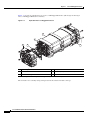
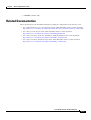
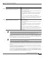
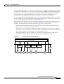
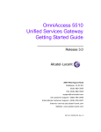
Figure 1-1 shows an exploded view of a Cisco 3230 Rugged Enclosure. (The design of the longer
Cisco 3270 Rugged Enclosure is similar.)
Figure 1-1
Exploded View of a Rugged Enclosure
4
270439
3
1
2
5
1
I/O end cap1
2
Wiring card
3
Card stack
4
Extrusion (body of the enclosure)
5
Antenna end cap
1. This end cap shows four serial ports, but the typical configuration has two serial ports.
The enclosures are sealed by using O-rings between the extrusion and the end caps.
Cisco 3200 Series Router Hardware Reference
1-2
OL-5816-10
Chapter 1
Cisco 3200 Rugged Enclosures
Cisco 3270 Rugged Enclosure
The Cisco 3270 Rugged Enclosure operates in a temperature range from –40 to +165°F (–40 to +74°C)
when all ports are copper. If the Cisco 3270 Router includes a fiber-optic port, it operates at a
temperature range from –40 to +147°F (–40 to +64°C).
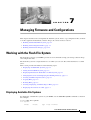
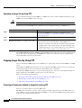
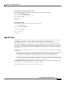
The Cisco 3270 Rugged Enclosure is designed to meet NEMA4 requirements. Figure 1-2 shows an
example of a fully assembled Cisco 3270 Rugged Enclosure. Note the greater length to accommodate
the Cisco 3270 Rugged Router card and future expansion.
Cisco 3270 Rugged Enclosure
270440
Figure 1-2
Cisco 3200 Series Router Hardware Reference
OL-5816-10
1-3
Chapter 1
Cisco 3200 Rugged Enclosures
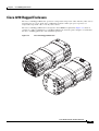
Cisco 3270 Router Card Stack
The Cisco 3270 Rugged Enclosure supports the following configurations:
•
One Cisco 3270 Rugged Router card
•
Up to three Wireless Mobile Interface Cards (WMICs)
•
One Serial Mobile Interface Card (SMIC)
•
One Fast Ethernet Switch Mobile Interface Card (FESMIC)
•
One Cisco Mobile Router Power Card (MRPC)
A base configuration includes one of each of the following: Cisco 3270 Rugged Router card, SMIC,
FESMIC, and MRPC.
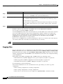
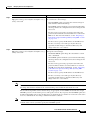
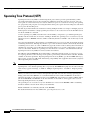
In the Cisco 3270 Rugged Enclosure, the cards should be stacked in the order shown in Figure 1-3. The
figure includes three optional WMICs. If WMICs are added, the first WMIC should be installed on the
bottom of the stack, and the next two WMICs should be installed at the top of the stack.
Figure 1-3
Example of a Cisco 3270 Router Card Stack with Three Optional WMICs
8
7
6
270441
5
4
3
2
9
1
1
WMIC 1
2
MRPC
3
MARC
4
SMIC
5
FESMIC
6
WMIC 2
7
WMIC 3
8
Small-form-factor pluggable
(SFP) module
9
Second PCI bus
Cisco 3200 Series Router Hardware Reference
1-4
OL-5816-10
Chapter 1
Cisco 3200 Rugged Enclosures
Cisco 3230 Rugged Enclosure
The Cisco 3230 Rugged Enclosure is designed to accommodate the Mobile Access Router Card
(MARC). This enclosure operates in a temperature range from –40 to 165°F (–40 to +74°C), and is
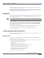
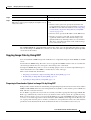
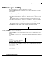
certified to meet NEMA4 requirements. Figure 1-4 shows an example of a Cisco 3230 Rugged
Enclosure.
Cisco 3230 Rugged Enclosure
270442
Figure 1-4
1
2
1
Front of the enclosure (I/O end cap)1
2
Back of the enclosure (antenna end cap)
1. This end cap shows four serial ports, but the typical configuration has two serial ports.
Cisco 3200 Series Router Hardware Reference
OL-5816-10
1-5
Chapter 1
Cisco 3200 Rugged Enclosures
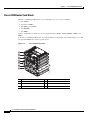
Cisco 3230 Router Card Stack
The Cisco 3230 Rugged Enclosure can accommodate up to seven cards, including:
•
One MARC
•
Up to three WMICs
•
One SMIC (or no SMIC)
•
One FESMIC
•
One MRPC
A basic configuration includes one of each of the following: MARC, SMIC, FESMIC, WMIC, and
MRPC.
In the Cisco 3230 Rugged Enclosure, the cards should be stacked in the order shown in Figure 1-5. The
two optional WMICs are on the top of the stack.
Figure 1-5
Cisco 3230 Router Stack
7
6
5
4
3
2
270443
1
1
WMIC 1
2
MRPC
3
MARC
4
SMIC
5
FESMIC
6
WMIC 2
7
WMIC 3
Cisco 3200 Series Router Hardware Reference
1-6
OL-5816-10
Chapter 1
Cisco 3200 Rugged Enclosures
Rugged Enclosure End Caps
Each Cisco 3200 Rugged Enclosure has two end caps: an antenna end cap that connects to the back of
the enclosure, and an I/O end cap that connects to the front of the enclosure. The port configurations of
the I/O end caps vary, based on the contents of the enclosure. For example, the number and location of
antenna ports installed on the antenna end cap depend on how many WMICs are installed in the
enclosure.
Note
To prevent exposure to the elements, we recommend using the protective port covers (provided) on ports
that are not in use and using port covers (provided) on the mating cables.
Antenna End Cap
The antenna end cap has four antenna ports on the flat side and two ports on the top surface. The end cap
is used with the Cisco 3270 Rugged Enclosure or the Cisco 3230 Rugged Enclosure. The antenna ports
are connector type RP-TNC. Each RP-TNC is connected internally to a WMIC. Typically, two antenna
ports are used to support each WMIC. If fewer than three WMICs are installed, the unused antenna
connector ports are sealed with a cap to protect them from the environment.
Cisco 3200 Rugged Enclosure Antenna End Cap with a Mounting Bracket
135533
Figure 1-6
Note
By default, the Cisco 3205 WMIC uses the right antenna to receive and transmit data.
Cisco 3200 Series Router Hardware Reference
OL-5816-10
1-7
Chapter 1
Note
Cisco 3200 Rugged Enclosures
For additional information on antennas and antenna cables, see the “Antenna Basics” technical note at
http://www.cisco.com/en/US/products/hw/wireless/ps458/products_installation_guide_chapter09186a0
08007f74a.html
and the “Antenna Cabling” technical note at
http://www.cisco.com/en/US/tech/tk722/tk809/technologies_tech_note09186a00801c12c2.shtml
I/O End Caps for the Cisco 3200 Rugged Enclosures
The I/O end cap has multiple connectors for connecting power and data cables. The end cap
configurations shown in this section are fully populated; however, the number of ports and their
functions may differ, depending upon the number of WMICs in the system.
End Cap Fast Ethernet and WMIC Console Ports
Internally, five Fast Ethernet ports are available: one routed Fast Ethernet port on the router card and four
switched Fast Ethernet ports on the Fast Ethernet Switch Mobile Interface Card (FESMIC). When a
WMIC is installed in addition to the router, the WMIC Fast Ethernet port is connected internally to the
routed Fast Ethernet port on the router card or is connected to one of the switched Fast Ethernet ports on
the FESMIC to provide a communications link with the router. In contrast, the Serial Mobile Interface
Card (SMIC) and FESMIC communicate with the router through the bus. All the router Fast Ethernet
ports are addressed by using the slot/port format.
In typical configurations, the first WMIC Fast Ethernet port is connected to the routed Fast Ethernet port
on the router card. The Fast Ethernet ports of the second and third WMICs are connected to FESMIC
switched Fast Ethernet ports. The differences in the types of the router Fast Ethernet ports that the
WMICs are connected to affect how they are configured, as, for example, when uploading a Cisco IOS
image to a WMIC.
The WMIC runs an independent Cisco IOS image and when you configure the WMIC, the link forms an
internal LAN. In standard configurations, the WMIC Fast Ethernet port is never brought out to the end
cap.
The WMIC console port is brought out to the corresponding RJ-45 port on the I/O end cap, replacing a
Fast Ethernet port. If the router includes one WMIC, the EIA/TIA-232 WMIC console port replaces a
Fast Ethernet port on the end cap. If the router includes two WMICs, two WMIC EIA/TIA-232 console
ports replace two Fast Ethernet ports on the end cap.
Note
At present, even if the router contains no WMICs, in standard configurations the maximum three Fast
Ethernet ports are brought out to the end cap. Unused EIA/TIA-232 ports are sealed.
Cisco 3200 Series Router Hardware Reference
1-8
OL-5816-10
Chapter 1
Cisco 3200 Rugged Enclosures
Cisco 3270 Router I/O End Cap
Figure 1-7 shows the Cisco 3270 Router I/O end cap.
Figure 1-7
Cisco 3270 Router End Cap
1
3
2
5
6
4
7
15
14
13
270447
12
11
10
9
8
1
Router console port
2
FE0 port
3
FE1 port
4
FE0X port
5
GE0 (Gigabit Ethernet) port
6
Fiber-Optic port (shown) or Copper Gigabit
Ethernet (GE1) port
7
USB0 (bottom) and USB1 (top) ports
8
Ser2 Smart Serial port
9
Power input
10 Ser1 EIA/TIA-232 (DCE) port
11 AUX port
13 FE1X port or WMIC 3 console port
12 Ser0 EIA/TIA-232 (DCE) port
1
14 FE2X port or WMIC 2 console port1
15 FE3X port or WMIC 1 console port1
1. The configuration of the port is set at the factory and labeled accordingly.
The RJ-45 connectors identified as 8, 9, and 10 are Fast Ethernet ports or WMIC console ports,
depending on the configuration of the system. For example, if two WMICs have been added to the router,
RJ-45 ports 8 and 9 are labeled WMIC 1 and WMIC 2. Port 10 is labeled FE1X.
Cisco 3200 Series Router Hardware Reference
OL-5816-10
1-9
Chapter 1
Note
Cisco 3200 Rugged Enclosures
The connectors are sealed at the factory with captive dust covers (not shown) that seal the ports and
protect the pins. The dust covers should be used to seal the ports when the ports are not covered by cable
connectors.
Fiber Optic Connector IP–67 Integrity
When the fiber-optic port is not connected or otherwise in use, the protective cover should be used to
seal the port. To seal the fiber-optic port when it is connected to a cable, use connectors that maintain
IP-67 integrity. The part numbers for the connectors are Tyco 1828618–1 and Tyco 1828618–2.
Caution
When connecting fiber-optic cables, observe all standard procedures for safety, and maintain a clean
connection.
Power Connector IP-67 Integrity
To seal the Tyco DC Power input power connector and maintain IP-67 integrity, use the following parts:
•
796094-2–CPC housing
•
66101-3–contact
•
207489-1–boot
•
207490-1–cable (grip size 11)
Smart Serial Port External Seal for System Integrity
When the Smart Serial port is not connected or otherwise in use, the protective cover should be used to
seal the port. To seal the Smart Serial port when the port is connected to a cable, complete the steps in
Appendix A, “Smart Serial Port External Seal.” in the Cisco 3200 Series Router Hardware Reference.
Cisco 3200 Series Router Hardware Reference
1-10
OL-5816-10
Chapter 1
Cisco 3200 Rugged Enclosures
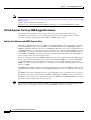
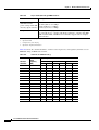
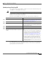
USB Flash Storage Device Caveat
In some cases, using two USB flash storage devices causes unpredictable results (CSCsd11136).
If one USB flash storage device is plugged into a USB port and a second USB flash storage device is
plugged into or unplugged from the other port, an error might occur (CSCsd44152). The error message
is, “USB_HOST_STACK-6-USB_FLASH_READY_TEST_TIME: USB flash 'Ready' test time over
4 seconds.”
If an unsupported USB flash storage device is plugged into a USB port, an error might occur
(CSCsd44152). The error message is, “Failed to enumerate a USB device as not able to read the device's
description.”
To correct the problems, remove any unsupported USB flash storage device and use only one supported
device in one of the two USB ports. The Cisco-supported flash storage devices listed below.
Item#
Vendor
Part Number
16-3153-01
SANDISK
SDUJGU0-256-926
16-3153-01
M-SYSTEMS
8U-52E-0256-12A01C
16-3152-01
SANDISK
SDUJGU0-128-926
16-3152-01
M-SYSTEMS
8U-52E-0128-12A01C
16-3151-01
SANDISK
SDUJGU0-64-926
16-3151-01
M-SYSTEMS
8U-52E-0064-12A01C
Cisco 3200 Series Router Hardware Reference
OL-5816-10
1-11
Chapter 1
Cisco 3200 Rugged Enclosures
Cisco 3230 Router I/O End Cap
Figure 1-8 shows the Cisco 3230 Router I/O end cap. It has multiple connectors that can be used to
connect power and data cables.
Figure 1-8
Cisco 3230 Router End Cap
4
1
5
2
6
3
7
270444
8
9
10
11
1
WMIC 1 console port
2
WMIC 2 console port
3
WMIC 3 console port
4
FE0 port
5
FE1X port
6
FE2X or MARC FE0X port (for more
information, see the “Fast Ethernet Port
Cabling for the Cisco 3250 and Cisco 3230
Routers” section on page 1-16.)
7
AUX port
8
Router console port
9
Ser0 RS-232 (DCE) port
10 Ser1 RS-232 (DCE) port
11 Power input
Note
The connectors are sealed at the factory with captive dust covers (not shown) that seal the ports and
protect the pins. The dust covers should be used to seal the ports when the ports are not otherwise
covered by cable connectors.
Cisco 3200 Series Router Hardware Reference
1-12
OL-5816-10
Chapter 1
Cisco 3200 Rugged Enclosures
Protective End Cap Cover
A protective end cap cover (Figure 1-9) provides weatherproof protection for the ports on the end caps
of the Cisco 3200 Rugged Enclosure when the enclosure is installed outdoors. The protective end cap
cover also provides added protection for in-vehicle use, inhibiting corrosion on the ports and potential
damage from objects that are stored near the enclosure inside a vehicle.
The protective end cap cover has a ruggedized design for high reliability and NEMA4 compliance.
Figure 1-9
Cisco 3200 Rugged Enclosure Protective End Cap Cover
1
5
4
158086
2
3
1
Hinge point
2
NEC cable pass-through
3
Holes for 8–32 protective end cap cover
screws
4
Hinge/mounting bracket
5
Mounting bolt
Cisco 3200 Series Router Hardware Reference
OL-5816-10
1-13
Chapter 1
Cisco 3200 Rugged Enclosures
To attach the protective end cap cover to the enclosure, follow these steps (see Figure 1-10).
Figure 1-10
Protective End Cap Cover Installation
1
2
6
4
5
170106
3
1
Hinge bracket
2
Hinge point
3
Cable/service loop cavity
4
NEC pass-through
5
Gasket
6
Cap mounting
Step 1
Loosen the end cap mounting hardware (four 1/4-20 bolts), but do not remove the bolts.
Step 2
Slide the hinge brackets onto the right side and the left side of the end cap cover. The mounting tabs
should slide under the loosened bolts.
Step 3
Re-torque the two loosened bolts on the right side of the end cap cover to between 58 and 68 in-lb.
Step 4
Ensure that the gasket is fully seated in the protective end cap cover.
Step 5
Close the cover on the protective end cap cover and ensure that it is fully seated.
Step 6
Re-torque the end cap cover bolts on left side of the end cap cover to between 58 and 68 in-lb.
Step 7
Tighten the 8-32 protective cover screws (18 in-lb) until they are seated.
For sealing, we recommend Liquid Tight Connector, which is described at the following URL:
http://www.newark.com/NewarkWebCommerce/newark/en_US/mfr/brands.jsp?mfg=HUBB
Cisco 3200 Series Router Hardware Reference
1-14
OL-5816-10
Chapter 1
Cisco 3200 Rugged Enclosures
I/O End Cap Port Signals
This section describes the ports and port signals on the Cisco 3200 Rugged Enclosure I/O end caps.
Gigabit Ethernet Signal Limitations
Due to CPU and memory bus limitations, a Gigabit Ethernet port transmits and receives packets below
the line rate. The line rate is lower for small frames and higher for large frames.
Small packet streams on Gigabit Ethernet ports, such as 64-byte packet streams, support up to 24 percent
of full duplex, bidirectional line rate traffic without experiencing packet drops.
The 512-byte packet streams support up to 78 percent of full duplex, bidirectional line rate traffic. The
1518-byte packet streams support up to 88 percent of full duplex bidirectional line rate traffic.
At higher frame rates the RDRP receive drop counter (displayed by using the show controller g0/0
command) increases indicating dropped packets.
At higher frame rates for packet sizes greater than 512 bytes, the transmit underruns1 counter (displayed
by using the show int g0/0 or show int g0/1 command) increases. The transmit underruns might cause
CRC errors on the peer router.
Fast Ethernet Signals
A Cisco router identifies a Ethernet port interfaces by slot number and port number in the format of
slot/port. For example, the slot/port address of a Fast Ethernet interface on the Cisco 3230 Rugged
Enclosure is 0/0.
The Cisco 3270 Router Ethernet port signals are in compliance with IEEE 802.3. The interfaces support
the following:
•
Autonegotiation and parallel detection MII interface with extended register capability for
10/100BASE-TX or 10/100/1000BASE-TX connections.
•
Full-duplex and half-duplex modes.
•
3.3V operation low power consumption (300 mW typical).
•
Low-power sleep mode.
•
Robust baseline wander correction performance.
•
MDIX support (Fast Ethernet and Gigabit Ethernet copper only).
•
Jumbo Frame (4400 bytes) support on Gigabit Ethernet interfaces.
•
10BASE-T or 100BASE-TX using a single Ethernet connection.
•
10BASE-T, 100BASE-TX, or 1000BASE-TX using a Gigabit Ethernet copper connection.
•
100BAFX/100LX, 1000BASE-SX, 1000BASE-LX/LH for Gigabit Ethernet fiber-optic
connections. (The speed is not configurable.)
•
Standard carrier signal multiple access collision detect (CSMA/CD) or full-duplex operation.
•
Integrated programmable LED drivers.
1. Transmit underrun–an error on interfaces when the data is not ready on the memory bus when the system
attempts to transmit the data; a bad packet is transmitted.
Cisco 3200 Series Router Hardware Reference
OL-5816-10
1-15
Chapter 1
Cisco 3200 Rugged Enclosures
The Cisco 3230 Router Ethernet port signals are in compliance with IEEE 802.3. The interfaces support
the following:
•
Autonegotiation and parallel detection MII interface with extended register capability for
10/100BASE-TX connections
•
Full-duplex and half-duplex modes
•
3.3V operation low power consumption (300 mW typical)
•
Low-power sleep mode
•
10BASE-T or 100BASE-TX using a single Ethernet connection
•
Robust baseline wander correction performance
•
Standard carrier signal multiple access collision detect (CSMA/CD) or full-duplex operation
•
Integrated programmable LED drivers
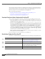
Fast Ethernet Port Cabling for the Cisco 3250 and Cisco 3230 Routers
Most Cisco 3200 Series router Ethernet ports support autodetection. If the device that the router is
connected to also supports autodetection, the choice of a straight-through or crossover Ethernet cable
does not matter. However, the Cisco 3250 router MARC FE0X port does not support autodetection.
To connect a port marked MARC FE0X to a routing Ethernet port that does not support autodetection,
use a straight-through Ethernet cable. To connect a MARC FE0X port to a hub, switch, a router hub, or
switch port, use a crossover Ethernet cable. Table 1-1 shows the connections.
Table 1-1
General Guidelines for MAR Fast Ethernet Port Cabling
Ports
Ports marked FE0X, FE1X,
and so forth
Server, Workstation, or Personal
Computer Ethernet Link
Hub, Switch, Uplink Router
Ethernet Hub, or Switch
Straight-through cable
Crossover cable
Ports marked FE0, FE1, and Crossover cable
so forth
Straight-through cable
For example, a port marked FE0X requires a crossover Ethernet cable to establish the Ethernet link
between a Cisco 3250 router and a hub. A port that does not support autodetection marked FE0 requires
a straight-through Ethernet cable to establish the Ethernet link between a Cisco 3250 router and a hub.
For additional information on cable pin assignments, see the “Cable Pinouts” chapter of the Cisco
Content Services Switch Getting Started Guide at:
http://www.cisco.com/en/US/products/hw/contnetw/ps789/products_installation_guide_chapter09186a
00805f718d.html
Cisco 3200 Series Router Hardware Reference
1-16
OL-5816-10
Chapter 1
Cisco 3200 Rugged Enclosures
Console Port Signals
You can connect to the router or to a Wireless Mobile Interface Card (WMIC) by using a console cable
to connect to the console interfaces.
The console port signals:
•
Are asynchronous serial DCE
•
Support 9.6-kbps, 19.2-kbps, 38.4-kbps, 57.6-kbps, and 115.2-kbps baud rates
•
Support full modem control of DTR, DSR, RTS, and CTS signals
AUX Port Signals
The AUX port is a serial asynchronous port that supports the following speeds:
•
Cisco 3270 Rugged Router card in the Cisco 3270 Router: 1.2 kbps, 2.4 kbps, 4.8 kbps, 9.6 kbps,
19.2 kbps, 38.4 kbps, 57.6 kbps, 115.2 kbps, and 460 kbps.
•
Mobile Access Router Card (MARC) in the Cisco 3230 Router: 1.2 kbps, 2.4 kbps, 4.8 kbps,
9.6 kbps, 19.2 kbps, 38.4 kbps, 57.6 kbps, and 115.2 kbps.
The AUX port supports the following:
•
Asynchronous serial DTE
•
5 to 8 data bits
•
1, 1.5, or 2 stop bits
•
Odd, even, or no parity
•
Flow control by using RTS, CTS, DTR, and CDC signals
Cisco 3200 Series Router Hardware Reference
OL-5816-10
1-17
Chapter 1
Cisco 3200 Rugged Enclosures
Cisco 3200 Rugged Enclosure LED Indications
This section describes the LED indications for the Cisco 3200 Rugged Enclosure I/O end caps.
Note
The behavior of the WMIC LEDs is described in the “WMIC Console LEDs” section on page 1-19.
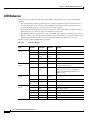
Cisco 3270 Rugged Enclosure I/O End Cap LED Indications
Table 1-2 lists the LEDs for the Cisco 3270 Rugged Enclosure I/O end caps and their indications.
Table 1-2
LEDs for the Cisco 3270 Rugged Enclosure End Cap
LED
Indication
Cisco 3270 Rugged Router card
Solid green: OK.
Blinking: Booting and self-testing.
Black: Not OK or the power is off.
Serial Status/Link (1 status/link
LED per serial port)
Solid green: Link OK.
Black: No link is detected.
Amber blink: Activity.
Fast Ethernet
(1 LED per port, except for the
fiber-optic port, which has no
LEDs)
Link LED
Solid green: Link OK.
Black: No link is detected.
Gigabit Ethernet
(2 LEDs per port)
Link LED
Solid green: Link OK.
Black: no link is detected.
Activity LED
Black: No activity and no connection.
Green blink: Activity.
Activity LED
Solid green: Link OK.
Black: No activity.
Green blink: Activity.
Console
Solid green: Link OK.
Black: No activity.
Green blink: Activity.
WMIC Console (Installation or
Operation Mode)
For installation mode, see Table 1-4 on page 1-19.
For operation mode, see Table 1-5 on page 1-20.
Cisco 3200 Series Router Hardware Reference
1-18
OL-5816-10
Chapter 1
Cisco 3200 Rugged Enclosures
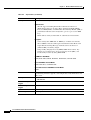
Cisco 3230 Rugged Enclosure I/O End Cap LED Indications
Table 1-3 lists the LEDs for the Cisco 3230 Rugged Enclosure I/O end caps and their indications.
Table 1-3
LEDs for Cisco 3230 Router I/O End Caps
LED
Indication
MARC
Solid green: OK.
Blinking: Booting and self-testing.
Black: Not OK or the power is off.
Serial Status/Link (1 status/link LED per Solid green: Link OK.
serial port)
Black: No link is detected.
Amber blink: Activity.
Fast Ethernet (2 LEDs per Fast Ethernet
port)
Link LED
Solid green: Link OK.
Black: No link is detected.
Activity LED
Black: No activity.
Green blink: Activity.
WMIC Console (Installation or Operation For installation mode, see Table 1-4 on page 1-19.
Mode)
For operation mode, see Table 1-5 on page 1-20.
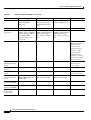
WMIC Console LEDs
WMIC console LEDs function in installation mode or operational mode. The WMIC is set to the
installation mode by default. To change the function of the WMIC, use the station role command.
Table 1-4 shows the status of the LEDs when the WMIC is in installation mode (signal strength).
Table 1-4
WMIC Installation Mode
RSSI (dBm)
Status LED
Radio LED
> –51
Steady
Steady
–58 to –54
Fast blinking (16 Hz)
Steady
–60 to –57
Slow blinking (4 Hz
Steady
–63 to –60
Very slow blinking (2 Hz)
Steady
–66 to –63
Black
Steady
–69 to –66
Black
Fast blinking (16 Hz)
–72 to –69
Black
Slow blinking (4 Hz
–75 to –72
Black
Very slow blinking (2 Hz)
< –75
Black
Black
Cisco 3200 Series Router Hardware Reference
OL-5816-10
1-19
Chapter 1
Cisco 3200 Rugged Enclosures
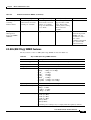
Table 1-5 shows the status of the LEDs when the WMIC is in operational mode.
Table 1-5
WMIC Operational Mode
Indication
Status LED
Radio LED
Green steady
At least one bridge is associated.
—
Red steady
Loading firmware.
Firmware failure.
Green blink
No bridges are associated.
Transmitting or receiving packets on
the radio port.
Amber blink
General warning.
Maximum retries or buffer full.
Black (no light)
—
Default.
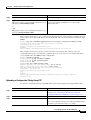
Thermal Plates
Cisco 3200 Rugged Enclosures use thermal plates and Wedge Loks to transfer heat from the cards to the
extrusion. Figure 1-11 shows a card with thermal plates. The conduction cooling removes the need for
internal fans.
Figure 1-11
Router Card with Thermal Plates
2
3
270446
4
1
1
Power connector
2
Wedge Lok
3
ISA bus
4
PCI bus
Cisco 3200 Series Router Hardware Reference
1-20
OL-5816-10
Chapter 1
Cisco 3200 Rugged Enclosures
Mounting Brackets
Mounting brackets are available for the enclosures.
The notches in the mounting brackets allow you to temporarily install the bracket without the router in
place. The bolts for the notches in the mounting bracket can be installed on the enclosure before the other
bolts are installed. The partially installed bolts provide enough support to allow you to install the router
in the bracket, and then install and tighten the remaining bolts. The torque values for the mounting
bracket screws are from 58 to 68 in-lb.
Figure 1-12 shows the Cisco 3270 Rugged Enclosure mounting bracket.
Cisco 3270 Rugged Enclosure Mounting Bracket
170050
Figure 1-12
Cisco 3200 Series Router Hardware Reference
OL-5816-10
1-21
Chapter 1
Cisco 3200 Rugged Enclosures
Figure 1-13 shows the dimensions of the Cisco 3270 Rugged Enclosure mounting bracket.
Figure 1-13
Cisco 3270 Rugged Enclosure Mounting Bracket Dimensions
232600
3.9
Figure 1-14 shows the Cisco 3230 Rugged Enclosure mounting bracket.
Cisco 3230 Rugged Enclosure Mounting Bracket
127452
Figure 1-14
Cisco 3200 Series Router Hardware Reference
1-22
OL-5816-10
Chapter 1
Cisco 3200 Rugged Enclosures
Figure 1-15 shows the dimensions of the Cisco 3230 Rugged Enclosure mounting bracket.
Cisco 3230 Rugged Enclosure Mounting Bracket Dimensions
232599
Figure 1-15
Cisco 3200 Series Router Hardware Reference
OL-5816-10
1-23
Chapter 1
Cisco 3200 Rugged Enclosures
Cisco 3200 Series Router Hardware Reference
1-24
OL-5816-10
CH A P T E R
2
Cisco 3270 Rugged Router Card
This chapter describes the features of the Cisco 3270 Rugged Router card. The Cisco 3270 Rugged
Router card is the core component of a Cisco 3270 Mobile Access Router. It is compatible with other
Cisco 3200 Series router mobile interface cards (MICs), such as the Wireless Mobile Interface Card
(WMIC). The Cisco 3270 Rugged Router card is also available as a standalone router card (to be
embedded into a third-party enclosure).
The Cisco 3270 Rugged Router card includes the host processor, memory, ports, and LED signals.
Additional components provide power and link interfaces; for example, the Serial Mobile Interface Card
(SMIC) provides the serial interfaces. The exact configuration of your router will vary, depending on
how the device was configured by the vendor.
The Cisco 3270 Rugged Router card has the following features:
•
Support for the PC/104-Plus form factor.
•
Dual 32-bit PCI buses, one running at 66 MHz and the other at 25 MHz.
•
256-MB, 64-bit, unbuffered, double data rate (DDR), synchronous DRAM.
•
64-MB, 16-bit flash memory.
•
Two Fast Ethernet ports with autonegotiation.
•
Two Gigabit Ethernet port signal sets with autonegotiation; the router can be ordered with support
for one fiber-optic port and one copper port, or with two copper ports.
•
Console port signals, with modem flow control.
•
Asynchronous EIA/ITA 232 serial port signals with 5V auxiliary power for GPS/AUX devices.
•
Two USB 2.0 high-speed (480-Mbps) port signal sets.
•
High-performance hardware encryption processor.
•
Zeroization to clear up any trace of user data or binary code.
•
Industrial-grade components that support local component ambient temperature ranges. 1
•
An enhanced PCI-to-PCI bridge that supports asynchronous operation. The asynchronous bridge
allows each port to run from a separate independent clock for the highest performance. A
synchronous clock forces one side of the bridge to slow down to support a slow device on the other
side of the bridge; asynchronous bridge clock domains can be arbitrarily different.
1. Except optical small form-factor pluggable (SFP) modules. Optical SFPs have a temperature range of -40 to
+85°C device temperature as opposed to local component ambient temperature.
Cisco 3200 Series Router Hardware Reference
OL-5816-10
2-1
Chapter 2
Note
Cisco 3270 Rugged Router Card
The Cisco 3270 router can be ordered with one Gigabit Ethernet copper interface and one fiber optic
interface, or with two Gigabit Ethernet copper interfaces. The port configurations are not
interchangeable.
The PCI bus connector supports communication between the Serial Mobile Interface Card (SMIC), the
Fast Ethernet Switch Mobile Interface Card (FESMIC), and the Cisco 3270 Rugged Router card. The
Wireless Mobile Interface Card (WMIC) communicates with the router through an internal Fast Ethernet
port. The WMIC is configured through an independent console port; the card draws power only from the
bus.
Note
For detailed information about the Cisco 3270 Rugged Router card, such as header pin assignments, see
the “Cisco 3200 Series Mobile Access Router Technical Reference” (OL-1927). This book is a
controlled document. Qualified system integrators can contact Cisco Marketing to receive a copy.
Cisco 3270 Rugged Router Card Component Systems
The industry-standard architecture (ISA) buses and peripheral component interconnect (PCI) buses on
the Cisco 3200 Series Mobile Access Router cards provide power to the components on the cards. Both
buses comply with the PC/104-Plus standard. The ISA bus allows PC/104-Plus ISA signals to pass
through the card bus, but the Cisco cards do not use any of the signals.
The PCI bus signals allow the Cisco SMIC and FESMIC to communicate with the Cisco 3270 Rugged
Router card. The WMIC draws power from the bus, but it does not communicate with the router through
the buses. It communicates with the router through an internal Fast Ethernet port. Non-Cisco cards
cannot communicate with the router over the PCI bus.
Caution
If you add non-Cisco cards that generate signals on the PCI bus, the router might shut down. Please do
not add non-Cisco cards that generate signals on the PCI bus.
Cisco 3200 Series Router Hardware Reference
2-2
OL-5816-10
Chapter 2
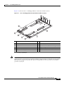
Cisco 3270 Rugged Router Card
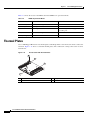
Figure 2-1 shows the Cisco 3270 Rugged Router card header and bus locations.
Figure 2-1
Cisco 3270 Rugged Router Card Header and Bus Locations
1
2
3
4
270445
5
12
6
11
10
7
9
8
1
Gigabit Ethernet 1 (fiber-optic or copper)
2
Gigabit Ethernet 0
3
Fast Ethernet 1
4
Fast Ethernet 0
5
USB ports and USB LEDs
6
PCI bus for future expansion
7
ISA bus
8
Jumper for optional Fast Ethernet 01
9
Optional Fast Ethernet 0
10 Multifunction (AUX, console, LED) header
2
11 GPIO Zeroization pins and USB header
12 PCI bus
1. Factory set. Do not modify.
2. General Purpose Input/Output.
Note
The PC/104-Plus standard requires that the PCI bus and the ISA bus use keying features in the standard
stacking headers to guarantee proper module installation. On the PCI bus, pin D30 is removed and the
D30 opening is plugged. On the ISA bus, pin C19 and pin B10 are removed, and the C19 and B10
openings are plugged.
Cisco 3200 Series Router Hardware Reference
OL-5816-10
2-3
Chapter 2
Cisco 3270 Rugged Router Card
Cisco 3270 Rugged Router Card Power Requirements
The Cisco 3270 Rugged Router card uses +3.3 V, +5 V, and +12 V power sources. Typical power
consumption is 20 W. The maximum calculated wattage is 26.5 W.
Table 2-1
Cisco 3270 Rugged Router Card Voltages
Voltage
Current
Power
+3.3 V
1.8 A
5.9 W
+5.0 V
4.0 A
20.0 W
+12.0 V
0.05 A
0.6 W
Power Connections (AUX)
The speed of the AUX port for the Cisco 3270 Rugged Router card can be configured as 2400, 4800,
9600, 19200, 38400, 57600, 115200, 230400, or 460800 bps. Use the line aux linenumber speed
command to modify the speed of the port.
A +5V power supply is provided for devices connected to the AUX port. A Global Positioning System
(GPS) modem is used as an example in this section. Typically the +5V power supply current to GPS
modems should be limited to less than 200 mA.
Table 2-2 shows the pin assignments for power on the AUX port.
Table 2-2
Cisco 3270 Rugged Router Card Multifunction Header Pin Assignments for Power
Pin
Signal
Description
Function
9
GND
Ground
GND
26
+5 V
+5 V DC Power Supply
Power
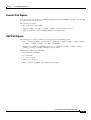
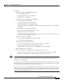
Hardware Encryption Processor
The Cisco 3270 Rugged Router card integrated security engine (SEC 2.0) is optimized to handle all the
algorithms associated with IPSec, Secure Sockets Layer (SSL)/Transport Layer Security (TLS), Secure
Real-time Transport Protocol (SRTP), 802.11i, Internet SCSI (iSCSI), and Internet key exchange (IKE)
processing. The security engine contains four crypto channels, a controller, and a set of crypto execution
units (EUs).
The SEC can act as a master on the internal bus. This allows the SEC to alleviate the data movement
bottleneck normally associated with slave-only cores. The host processor accesses the SEC through its
device drivers, using system memory for data storage. The SEC resides in the peripheral memory map
of the processor; therefore, when an application requires cryptographic functions, it creates descriptors
for the SEC that define the cryptographic function to be performed and the location of the data.
The SEC bus-mastering capability permits the host processor to set up a crypto channel with a few short
register writes, leaving the SEC to perform reads and writes on system memory to complete the required
task.
Cisco 3200 Series Router Hardware Reference
2-4
OL-5816-10
Chapter 2
Cisco 3270 Rugged Router Card
The EUs are:
•
Public Key Execution Unit (PKEU) supporting:
– RSA and Diffie-Hellman
– Programmable field size up to 2048 bits
– Elliptical curve cryptography
•
Data Encryption Standard Execution Unit (DEU)
– Data Encryption Standard (DES)
– Triple Data Encryption Standard (3DES)
– Two-key (K1, K2) or three-key (K1, K2, K3)
– Ethernet Bundling Controller (EBC) and Cipher Block Chaining (CBC) modes for both DES
and 3DES
•
Advanced Encryption Standard Unit (AESU)
– Implements the Rinjdael symmetric key cipher
– Key lengths of 128, 192, and 256 bits
– ECB, CBC, CCM, and AES Counter Mode (a block cipher that encrypts 128-bit blocks of data
at a time with a 128-bit encryption key)
•
ARC Four execution unit (AFEU)
– A stream cipher compatible with the RC4 algorithm
– 40- to 128-bit programmable key
•
Message Digest Execution Unit (MDEU)
– Secure Hash Algorithm (SHA) with a 160-bit or 256-bit message digest
– Message Digest 5 (MD5) with a 128-bit message digest
– Hash-based Message Authentication Code (HMAC) with either algorithm
•
Random Number Generator (RNG)
•
Four crypto channels, each supporting multi command descriptor chains
– Static or dynamic assignment of crypto-execution units through an integrated controller
– Buffer size of 256 bytes for each EU, with flow control for large data sizes
Caution
Zeroization is a feature that erases all potentially sensitive information from the router. It is disabled by
default on the router. When Zeroization is not configured on the router, the AUX port functions as a
modem port or a terminal port.
Zeroization is configured through the command-line interface (CLI), but it cannot be activated through
the CLI. Zeroization is activated by actuating a custom switch connected to the GPIO pins or an actuator
(such as a push button) that must be attached to the AUX port.
There is no way for the router to reliably determine whether a device attached to the AUX port is an
actuator. Therefore, any device attached to the AUX port could potentially trigger declassification. When
declassification is enabled through the CLI, we recommend that you do not use the AUX port for any
function other than declassification.
Cisco 3200 Series Router Hardware Reference
OL-5816-10
2-5
Chapter 2
Cisco 3270 Rugged Router Card
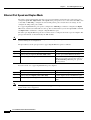
Ethernet Port Speed and Duplex Mode
The router cannot automatically negotiate port speed and duplex mode unless the connecting port is
configured speed auto, duplex auto, or no speed. If the port speed is set to a value other than auto, such
as 10, 100, or 1000-Mbps, configure the remote link partner port to match the local settings; do not
configure the link partner port to auto.
If a copper Gigabit Ethernet port speed is configured as 1000-Mbps, it must be configured as duplex
auto mode; otherwise the link will not come up. We recommend that you use the speed auto command
and duplex auto command to configure a Gigabit Ethernet port.
The fiber-optic Gigabit Ethernet port does not allow users to configure the mode as speed or duplex. The
port speed and mode are determined by the SFP module.
Note
Changing the Ethernet port speed and duplex mode configuration might shut down and reenable the
interface during the reconfiguration.
The procedure to set the port speed for a copper Gigabit Ethernet port is as follows:
Command
Purpose
Step 1
Router(config)# interface GigabitEthernet slot/port
Selects the Ethernet port to be configured.
Step 2
Router(config-if)# speed {10 | 100 | 1000 | auto}
Sets the speed of the Ethernet interface.
Default
Router(config-if)# no speed
Reverts to the default configuration (speed
auto). If you set the port speed to auto on a
10/100/1000-Mbps Ethernet port, speed is
autonegotiated.
To set the mode on a copper Gigabit Ethernet port to duplex?
Command
Purpose
Step 1
Router(config)# interface GigabitEthernet slot/port
Selects the Ethernet port to be configured.
Step 2
Router(config-if)# duplex [auto | full | half]
Sets the duplex mode of the Ethernet port.
Default
Router(config-if)# no duplex
Reverts to the default configuration (duplex
auto).
Note
The Gigabit Ethernet optical fiber interface only supports full duplex mode; a Cisco IOS command to
set the mode is not is supported.
Cisco 3200 Series Router Hardware Reference
2-6
OL-5816-10
Chapter 2
Cisco 3270 Rugged Router Card
Cisco 3270 Rugged Router Card Encryption Module
The integrated security engine (SEC 2.0) is optimized to handle all the algorithms associated with IP
security (IPSec), Secure Sockets Layer (SSL)/Transport Layer Security (TLS), Secure Real-time
Transport Protocol (SRTP), 802.11i, Internet Small Computer System Interface (iSCSI), and Internet
Key Exchange (IKE) processing. The security engine contains four crypto channels, a controller, and a
set of crypto execution units (EUs). The security engine can act as a master on the internal bus. This
allows the security engine to alleviate the data movement bottleneck normally associated with slave-only
cores.
The host processor accesses the security engine through device drivers, using system memory for data
storage. The security engine resides in the peripheral memory map of the processor; therefore, when an
application requires cryptographic functions, it simply creates descriptors for the security engine that
define the cryptographic function to be performed and the location of the data.
The security engine bus-mastering capability permits the host processor to set up a crypto-channel with
a few short register writes, leaving the security engine to perform reads and writes on system memory.
Security Engine Features
The execution units are:
•
Public Key Execution Unit (PKEU) supporting the following:
– RSA and Diffie-Hellman
– Programmable field size up to 2048 bits
– Elliptic curve cryptography
•
Data Encryption Standard Execution Unit (DEU)
– DES, 3DES
– Two key (K1, K2) or Three Key (K1, K2, K3)
– Electronic codebook (ECB) and cipher-block chaining (CBC) modes for both DES and 3DES
•
Advanced Encryption Standard Unit (AESU)
– Implements the Rinjdael symmetric key cipher
– Key lengths of 128, 192, and 256 bits
– ECB, CBC, Counter with CBC-MAC (CCM), and Counter modes
•
ARC Four execution unit (AFEU)
– Implements a stream cipher compatible with the RC4 algorithm
– 40- to 128-bit programmable key
•
Message Digest Execution Unit (MDEU)
– SHA-1 with 160-bit or 256-bit message digest
– MD5 with 128-bit message digest
– Keyed-Hash Message Authentication Code (HMAC) with either SHA or MD5 algorithm
(HMAC-MD5 or HMAC-SHA)
•
Random Number Generator (RNG)
Cisco 3200 Series Router Hardware Reference
OL-5816-10
2-7
Chapter 2
•
Cisco 3270 Rugged Router Card
4 crypto channels, each supporting multicommand descriptor chains
– Static and/or dynamic assignment of crypto execution units through an integrated controller
– Buffer size of 256 bytes for each execution unit, with flow control for large data sizes
•
256 (PBGA), 17x17 in., typical power 1.7 W
Temperature Sensor
A router equipped with the Cisco 3270 Rugged Router card includes a high-precision digital
thermometer and thermostat (DS1631). The temperature is sampled every 30 seconds. A warning is sent
to users by means of SNMP traps and by flashing the overtemperature LED if temperature falls below
-40ºC or exceeds +95ºC until the temperature falls back to its normal range.
Note
The signal and LED are available only on the Cisco 3270 Rugged Router card, not on the Cisco 3200
rugged enclosures.
Cisco 3270 Rugged Router Card MAC Address Allocation
Cisco 3270 Rugged Router card–equipped routers are allocated 37 MAC addresses, starting from the
base MAC address. A card-equipped Cisco 3270 Rugged Router supports four interface ports. Fast
Ethernet ports can be port 0 and 1. Gigabit Ethernet ports are port 2 and 3, depending on the router
configuration.
The assignments for MAC addresses are as follows:
•
Four MAC addresses for each of the for four Ethernet ports, offset 0 to 3 from the base MAC address.
•
One switch virtual interface (SVI) for the FESMIC; offset 4 from the base MAC address.
•
Thirty-two MAC addresses for FESMIC Spanning Tree Protocol (STP), offset 5 to 36 from the base
MAC address.
Cisco 3200 Series Router Hardware Reference
2-8
OL-5816-10
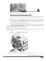
CH A P T E R
3
Mobile Access Router Card
The Mobile Access Router Card is one component of the Cisco 3200 Series Mobile Access Router. It
includes the host processor, memory, and headers for the Fast Ethernet, console, and auxiliary signals
for the router. Additional components provide power and link interfaces to the MARC. For example, the
4-port Serial Mobile Interface Card (SMIC) provides up to four Smart Serial interfaces. The exact
configuration of your router will vary, depending on how your vendor configured it.
Note
This section provides basic information about the MARC hardware for the purpose of performing simple
troubleshooting tasks, such as reconnecting a loose cable. To solve more difficult problems, please
contact your vendor.
The key features of the MARC include the following:
Caution
•
MPC8250 processor running 210 MHz at the CPU core, 150 MHz at the CPM core, and 60 MHz on
the Motorola 60x bus.
•
32 MB of flash memory.
•
128 MB of synchronous DRAM.
•
10/100 Fast Ethernet, full-duplex connection with autonegotiation.
•
Console connection with hardware/software flow control.
•
Asynchronous, EIA/TIA-232 serial connection with a 5 V auxiliary power supply for Global
Positioning System (GPS) and auxiliary (AUX) devices.
•
The AUX port speed can be configured as 2400, 4800, 9600, 19200, 38400, 57600, or 115200 bps.
Use the line aux linenumber speed command to modify the speed of the port.
•
A 32-bit PCI bus, version 2.1, running at 25 MHz.
•
Supports Zeroization when this featured is configured on the router.
Zeroization is a feature that erases all potentially sensitive information from the router. Zeroization is
configured through the command-line interface (CLI) and activated through an actuator attached to the
AUX port, such as a push button. Zeroization is disabled by default on the Cisco 3200 Series router.
When Zeroization is not configured on the router, the AUX port functions as a modem port or a terminal
port. When declassification is enabled through the CLI, we recommend that you do not use the AUX port
for any other function than declassification. This is because there is no way for the router to reliably
determine if a device attached to the AUX port is an actuator; therefore, any device attached to the AUX
port could potentially trigger declassification.
Cisco 3200 Series Router Hardware Reference
OL-5816-10
3-1
Chapter 3
Mobile Access Router Card
The PCI bus connector supports communication between the Serial Mobile Interface Card (SMIC), the
Fast Ethernet Switch Mobile Interface Card (FESMIC), and the Mobile Access Router Card. The
Wireless Mobile Interface Card (WMIC) communicates with the router through an internal Fast Ethernet
port and is configured through an independent console port; the WMIC only draws power from the bus.
MARC Component Systems
The industry-standard architecture (ISA) buses and peripheral component interconnect (PCI) buses on
the Cisco 3200 Series Mobile Access Router cards provide power to the components on the cards. Both
buses comply with the PC/104-Plus standard. The ISA bus allows PC/104-Plus ISA signals to pass
through the card bus, but the Cisco cards do not use any of the signals.
Caution
If you add non-Cisco cards that generates signal on the PCI bus, the router might shut down. Please do
not add non-Cisco cards that generate signals on the PCI bus.
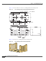
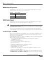
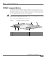
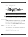
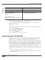
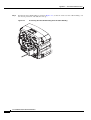
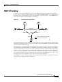
Figure 3-1 shows the MARC header and bus locations.
Figure 3-1
MARC Header and Bus Locations
1
74518
2
4
Note
3
1
PCI bus
2
ISA bus
3
Ethernet header
4
Multifunction header
The PC/104-Plus standard requires that the PCI Bus and the ISA bus use keying features in the standard
stacking headers to guarantee proper module installation. On the PCI bus, pin D30 is removed and the
D30 opening is plugged. On the ISA bus, pin C19 and B10 are removed, and the C19 and B10 openings
are plugged.
Cisco 3200 Series Router Hardware Reference
3-2
OL-5816-10
Chapter 3
Mobile Access Router Card
MARC Power Requirements
The MARC uses +3.3-V, +5-V, and +12-V power sources. Internal on-board DC-to-DC conversion
circuitry generates 1.8 V/1.5 A from the +3.3-V power source.
Table 3-1
MARC Voltages
Voltage
Current
Power
+5.0 V
0.3 A
1.5 W
+12.0 V
0.1 A
1.2 W
+3.3 V
2.0 A
6.6 W
MARC Router Signals
Cisco 3200 Series router cards do not support any ISA bus signals. The PCI bus connector supports
communication between Cisco 3200 Series Mobile Access Router cards.
Note
Non-Cisco MIC cards cannot use PCI signals. The use of PCI signals by non-Cisco cards causes
unpredictable results. You cannot add third-party devices that might attempt to communicate with the
SMIC through the ISA or PCI bus.
The signals are delivered through the shared, 34-pin multifunction header and the 10-pin Ethernet
header. LED signals and 5 V of power are also provided through the shared, 34-pin multifunction header.
Fast Ethernet Signals on the MARC
There is one fixed Fast Ethernet port on the MARC. A Cisco router identifies a Fast Ethernet interface
address by its slot number and port number, in the format slot/port. The slot/port address of a Fast
Ethernet interface on the MARC is 0/0.
The Fast Ethernet port signals are in compliance with IEEE 802.3. They are provided through the 10-pin
Ethernet header, which supports the following:
•
Autonegotiation and parallel detection MII interface with extended register capability for
10/100BASE-TX connection
•
Full-duplex and half-duplex modes
•
3.3-V operation low power consumption (300 mW typical)
•
Low-power sleep mode
•
10BASE-T and 100BASE-TX using a single Ethernet connection
•
Robust baseline-wander correction performance
•
100BASE-FX fiber-optic capabilities
•
Standard carrier signal multiple access collision detect (CSMA/CD) or full-duplex operation
•
Integrated, programmable LED drivers
The FastEthernet 0/0 port on the MARC is a Fast Ethernet router port. The FastEthernet ports on the
4-port FESMIC and the 2-port FESMIC are Fast Ethernet switch ports. The routing features supported
on the MARC cannot be configured on the FESMIC ports.
Cisco 3200 Series Router Hardware Reference
OL-5816-10
3-3
Chapter 3
Mobile Access Router Card
Console and Auxiliary Signals
You can configure the console interface by using Cisco IOS command line interface (CLI) commands.
The console interface and the AUX port can be accessed simultaneously. Also, the console port and the
AUX port can be accessed simultaneously. For example, you can connect a terminal to the console
interface and an external modem or a GPS modem to the AUX port.
The console port signals are provided through the multifunction header:
•
Asynchronous serial DCE
•
1.2-kbps, 2.4-kbps, 4.8-kbps, 9.6-kbps, 19.2-kbps, 38.4-kbps, 57.6-kbps, and 115.2-kbps baud rates
•
Support full modem control DTR, DSR, RTS, and CTS signals
The AUX port is a serial asynchronous port that works at speeds of 1.2 kbps, 2.4 kbps, 4.8 kbps,
9.6 kbps, 19.2 kbps, 38.4 kbps, 57.6 kbps, and 115.2 kbps.
The AUX port supports the following:
Note
•
Asynchronous serial DTE
•
Baud rates range from 1,200 to 115,000
•
5 to 8 data bits
•
1, 1.5, or 2 stop bits
•
Odd, even, or no parity
•
Flow control by using RTS, CTS, DTR, and CDC signals
When zeroization is enabled, it is activated through the polling of pin 25 on the AUX port.
A +5-V power supply is provided for a device connected to an AUX port. Typically the +5-V power
supply current to GPS modems should be limited to less than 200 mA.
Cisco 3200 Series Router Hardware Reference
3-4
OL-5816-10
CH A P T E R
4
Fast Ethernet Switch Mobile Interface Card
The Fast Ethernet Switch Mobile Interface Card is a mobile interface card (MIC) in a standard
PC/104-Plus form factor. FESMICs are components of the Cisco 3200 Series Mobile Access Router.
The 4-port FESMIC provides four sets of switched Fast Ethernet signals. The 2-port FESMIC provides
two sets of switched Fast Ethernet signals.
The key features of the FESMIC include the following:
•
Autosensing of switched Fast Ethernet interfaces.
•
Auto-MDIX (medium-dependent interface crossover). Auto-MDIX automatically detects and
corrects crossed Ethernet cabling.
•
Support for 802.1D standard bridging, 802.1Q trunking, and 802.1P class of service (CoS).
•
Layer 3 routing support between VLANs.
Only one FESMIC is supported in a Cisco 3200 Series router. Additional cards and components provide
power and link interfaces to the FESMIC. The exact configuration of your router will vary, depending
on how your vendor configured it.
Note
This section provides basic information about the FESMIC hardware for the purpose of performing
simple troubleshooting, such as reconnecting a loose cable. To solve more difficult problems, contact
your vendor.
The FESMIC draws power from the PCI and the ISA connectors. Table 4-1 shows the estimated power
consumption. Note that these are theoretical maximum wattages.
Table 4-1
FESMIC Estimated Power Consumption
Voltage
Current Draw
Power
Source
+5.0 V
0.2 A
1.0 W
ISA and PCI connectors
+3.3 V
2.3 A
7.7 W
PCI connectors
Cisco 3200 Series Router Hardware Reference
OL-5816-10
4-1
Chapter 4
Fast Ethernet Switch Mobile Interface Card
Autonegotiation and Auto-MDI/MDIX
All of the Fast Ethernet interfaces support Ethernet autonegotiation for the line transmission speed. Both
sides of the connection are automatically set to either 10BASE-TX or 100BASE-TX. Autonegotiation is
widely used on most Ethernet interfaces, and it is the default mode.
When a Fast Ethernet interface is enabled, one end of the link must perform media-dependent interface
(MDI) crossover (MDIX), so that the transmitter on one end of the data link is connected to the receiver
on the other end of the data link (a crossover cable is typically used). The Auto-MDIX feature eliminates
the need for crossover cabling by performing an internal crossover when a straight cable is detected
during the autonegotiation phase.
If autonegotiation is disabled, Auto-MDI/MDIX cannot work because there is no signal transmission at
initialization to sample the cabling with. Therefore, as in all systems not supporting the HP Auto-MDIX
feature, cabling must be correct for the devices being connected. The Auto-MDIX feature is disabled if
you explicitly set the line speed rather than leaving the default mode of autonegotiation. Although it is
possible to disable HP Auto-MDIX with autonegotiation enabled, the current software does not
implement an explicit command-line interface (CLI) command to allow you to disable Auto-MDIX
during autonegotiation.
Autonegotiation Enable
To enable autonegotiation, use the following configuration:
Router#(config) FastEthernet m/n
Router#(config-if) speed auto
where m is the slot and n is the port number.
Autonegotiation Disable
To disable autonegotiation and Auto-MDIX by forcing the line speed through a manual setting, enter the
following configuration commands:
Router#(config) FastEthernet m/n
Router#(config-if) speed 10
or
Router#(config) FastEthernet m/n
Router#(config-if) speed 100
MAC Address Allocation
The 4-port FESMIC stores 4 unique MAC addresses for the 10/100 Ethernet interfaces. The
2-port FESMIC stores 2 unique MAC addresses for the 10/100 Ethernet interfaces. In addition, 37 MAC
addresses are burned into Cisco 3270 Rugged Router card–equipped routers, and 33 MAC addresses are
burned into the Mobile Access Router Card (MARC) to support the FESMIC per-VLAN spanning tree
(PVST) and inter-VLAN routing features.
To provide support for up to 32 VLANs, and the 32 Spanning Tree Protocol (STP) sessions that might
be running, 32 unique MAC addresses are required for the bridge packet data unit (BPDU) IDs. In
addition, the FESMIC needs one MAC address for VLAN routing, bringing the total of number of MAC
addresses on the wired router to 34. To support future development, the MAC addresses are burned into
the Mobile Access Router Card (MARC), instead of the FESMIC.
Cisco 3200 Series Router Hardware Reference
4-2
OL-5816-10
Chapter 4
Fast Ethernet Switch Mobile Interface Card
FESMIC Component Systems
The ISA buses and PCI buses on the Cisco 3200 Series Mobile Access Router cards provide power to
the components on the cards. Both buses comply with the PC/104-Plus standard. The ISA bus allows
PC/104-Plus ISA signals to pass through the card bus, but the Cisco cards do not use any of the signals.
The PCI bus signals allow the Cisco cards to communicate. Non-Cisco cards cannot communicate with
the Cisco 3200 Series Mobile Access Router cards over the PCI bus.
Caution
If you add non-Cisco cards that generate signals on the PCI bus, the router might shut down. Do not add
non-Cisco cards that generate signals on the PCI bus.
Figure 4-1 shows the 2-port FESMIC header and bus locations.
Figure 4-1
2-port FESMIC Header and Bus Locations
2
3
95228
1
5
6
4
1
PCI bus
2
20-pin LED header
3
ISA bus
4
Rotary switch
5
FE0 Fast Ethernet header
6
FE1 Fast Ethernet header
Cisco 3200 Series Router Hardware Reference
OL-5816-10
4-3
Chapter 4
Fast Ethernet Switch Mobile Interface Card
Figure 4-2 shows the 4-port FESMIC header and bus locations.
Figure 4-2
4-port FESMIC Header and Bus Locations
2
3
81598
1
5
Note
6
7
4
8
1
PCI bus
2
20-pin LED header
3
ISA bus
4
Rotary switch
5-8
E0–E3 Fast Ethernet headers
The PC/104-Plus standard requires that the PCI bus and the ISA bus use keying features in the standard
stacking headers to guarantee proper module installation. On the PCI bus, pin D30 is removed and the
D30 opening is plugged. On the ISA bus, pin C19 and pin B10 are removed, and their openings are
plugged.
Signals for the FESMIC
The signals are delivered through 10-pin headers, with one set of Fast Ethernet signals per header. LED
signals and 5 V of power are provided through the 20-pin LED header. Cisco 3200 Series router cards
do not support any ISA bus signals.
The PCI bus connector supports communication between the FESMIC, the Serial Mobile Interface Card
(SMIC), and the Cisco 3270 Rugged Router card or Mobile Access Router Card (MARC). The Wireless
Mobile Interface Card (WMIC) communicates with the router through an internal Fast Ethernet port and
is configured through an independent console port; the WMIC draws power only from the bus.
The Fast Ethernet port signals are in compliance with IEEE 802.3. They are provided through the
Ethernet headers, which support the following:
•
Autonegotiation for 10/100BASE-TX connection
•
Full-duplex and half-duplex modes
•
Low-power sleep mode
•
10BASE-T and 100BASE-TX using a single Ethernet connection
•
Robust baseline-wander correction performance
•
Standard carrier signal multiple access collision detect (CSMA/CD) or full-duplex operation
•
Integrated LED drivers
Cisco 3200 Series Router Hardware Reference
4-4
OL-5816-10
Chapter 4
Fast Ethernet Switch Mobile Interface Card
The Fast-Ethernet ports on the 4-port FESMIC and the 2-port FESMIC are Fast Ethernet switch ports.
The switch ports support all Layer 2 features. The Fast-Ethernet 0/0 port on the Cisco 3270 Rugged
Router card and MARC is a Fast Ethernet router port. The routing features supported on the MARC
cannot be configured on the FESMIC ports.
FESMIC Rotary Switch Positions
A Cisco router identifies a Fast Ethernet interface address by its slot number and port number, in the
form of slot/port. The slot/port addresses of the Fast Ethernet interfaces on the FESMIC depend on the
position of the rotary switch.
For example, if the rotary switch on the 4-port FESMIC is in position 0, then the ports are identified as
1/0, 1/1, 1/2, and 1/3. If the rotary switch on the 2-port FESMIC is in position 0, the ports are identified
as 1/0 and 1/1.
Table 4-2 shows the mapping of the switch positions to the Cisco IOS slot numbers.
Table 4-2
Caution
FESMIC Rotary Switch Positions
Switch Position
Cisco IOS Slot Number
0
1
1
2
2
3
3–7
Not supported
The rotary switch positions must be unique and should not be assigned to more than one MIC.
•
If a MIC rotary switch is set to 3 or higher, the message is:
“MIC-3-SLOTNOTSUPPORTED: The MIC cannot operate when the rotary switch is in position 3.
Change the switch position to one of the supported, unused positions 0-2.”
•
If two or more MICs have the rotary switches set to the same position, or if one or more MICs are
in rotary switch positions 4 through 7, the router might crash after displaying the following error
message:
“Non-recoverable error occurred. Please check the rotary switch positions on the MIC cards for the
possible misconfiguration of the switch position.”
Table 4-3 shows the FESMIC Fast Ethernet signal assignments. The position of the rotary switch
determines the port assignments. Although the rotary switch has eight positions, only one of three
positions can be selected. The rotary switch position should be unique for each MIC.
Table 4-3
FESMIC Rotary Switch Positions and Signal Assignments
Rotary Switch Position
MIC Slot
Fast Ethernet Signal Assignments
0
1
FE 1/0
FE 1/1
FE 1/21
FE 1/31
1
2
FE 2/0
FE 2/1
FE 2/21
FE 2/31
2
3
FE 3/0
FE 3/1
FE 3/21
FE 3/31
1. For 4-port FESMIC only.
Cisco 3200 Series Router Hardware Reference
OL-5816-10
4-5
Chapter 4
Fast Ethernet Switch Mobile Interface Card
Cisco 3200 Series Router Hardware Reference
4-6
OL-5816-10
CH A P T E R
5
Serial Mobile Interface Card
The Serial Mobile Interface Card is one component of the Cisco 3200 Series Mobile Access Router. It
provides the router up to 4 high–speed sets of serial signals in both data terminal equipment (DTE) and
data circuit equipment (DCE) modes. Additional components provide power and link interfaces to the
SMIC. For example, the Cisco 3270 Rugged Router card provides the host processor, memory, and
headers for the Fast Ethernet, console, and auxiliary signals for the router. The exact configuration of
your router will vary, depending on how it was configured by your vendor.
Note
This section provides basic information about the SMIC hardware for the purpose of performing simple
troubleshooting, such as reconnecting a loose cable. To solve more difficult problems, please contact
your vendor.
Each SMIC provides the following:
Note
•
Support for two to four sets of serial signals with protocol support for High-Level Data Link Control
(HDLC), asynchronous, synchronous and octet-oriented PPP modes. The signals can be configured
to any serial standard (EIA/TIA-232, EIA/TIA-449, EIA/TIA-530, EIA/TIA-530A, EIA/TIA-X.21,
or CCITT V.35).
•
DCE and DTE mode support on each set of serial signals.
•
Speeds of 2 Mbps for synchronous data transfer and 115 kbps for asynchronous data transfer on
each serial interface. All serial standards reach 2 Mbps (for synchronous) except for the
EIA/TIA-232 standard, which supports up to 192K.
The Peripheral Component Interconnect (PCI) bus and the Industry Standard Architecture (ISA) bus use
keying features in the standard stacking headers to guarantee proper module installation. On the PCI bus,
pin D30 is removed and its opening is plugged. On the ISA Bus, pin C19 and pin B10 are removed, and
their openings are plugged.
The PCI bus connector supports communication between the SMIC, the Fast Ethernet Switch Mobile
Interface Card (FESMIC), and the Cisco 3270 Rugged Router card or Mobile Access Router Card
(MARC). The Wireless Mobile Interface Card (WMIC) communicates with the router through an
internal Fast Ethernet port and is configured through an independent console port; the WMIC only draws
power only from the bus.
Cisco 3200 Series Router Hardware Reference
OL-5816-10
5-1
Chapter 5
Serial Mobile Interface Card
SMIC Component Systems
Figure 5-1 shows the 2-port SMIC header and bus locations.
Figure 5-1
2-port SMIC Header and Bus Locations
3
95227
1
2
4
1
PCI bus
2
60-pin multifunction header for Serial 0 and
Serial 1 signals
3
ISA bus
4
Rotary switch
Figure 5-2 shows the 4-port SMIC header and bus locations.
Caution
If you add non-Cisco cards that generate signals on the PCI bus, the router might shut down. Do not add
non-Cisco cards that generate signals on the PCI bus.
Figure 5-2
4-port SMIC Header and Bus Locations
3
4
74519
1
2
5
1
PCI bus
2
60-pin multifunction header for Serial 2 and
Serial 3 signals
3
60-pin multifunction header for Serial 0 and
Serial 1 signals
4
ISA bus
5
Rotary switch
Cisco 3200 Series Router Hardware Reference
5-2
OL-5816-10
Chapter 5
Serial Mobile Interface Card
Signals for the SMIC
The Cisco Single-sideband (SSB) Serial standard supports the following:
•
EIA/TIA-232, EIA/TIA-449, EIA-530, EIA-530A, X.21, and V.35 standards in both DTE and DCE
modes.
•
Signals (SSB and LED) are provided through the 60-pin multifunction header(s).
The position of the rotary switch determines the port assignments. Although the rotary switch has eight
positions, only positions 0, 1, and 2 are supported on the 4-port SMIC, and only positions 0 and 1 are
supported on the 2-port SMIC.
Table 5-1 provides 4-port SMIC port assignments.
Table 5-1
4-port SMIC Rotary Switch Settings and Port Assignments
Position
MIC Slot
Port Assignments
0
1
Serial 1/0 Serial 1/1 Serial 1/2 Serial 1/3
1
2
Serial 2/0 Serial 2/1 Serial 2/2 Serial 2/3
2
3
Serial 3/0 Serial 3/1 Serial 3/2 Serial 3/3
Table 5-2 provides the 2-port SMIC port assignments.
Table 5-2
2-port SMIC Rotary Switch Settings and Port Assignments
Position
MIC Slot
Port Assignments
0
1
Serial 1/0 Serial 1/1
1
2
Serial 2/0 Serial 2/1
4-Port SMIC Rotary Switch Positions
Table 5-3 shows the 4-port SMIC serial signal assignments. The position of the rotary switch determines
the port assignments. Although the rotary switch has 8 positions, only 1 of 4 positions can be selected.
The rotary switch position should be unique for each mobile interface card (MIC) card.
Table 5-3
4-port SMIC Rotary Switch Positions and Serial Set Signal Assignments
Rotary Switch Position
MIC Slot
Signal Assignments
0
1
Serial 1/0 Serial 1/1 Serial 1/2 Serial 1/3
1
2
Serial 2/0 Serial 2/1 Serial 2/2 Serial 2/3
2
3
Serial 3/0 Serial 3/1 Serial 3/2 Serial 3/3
3
4
Serial 4/0 Serial 4/1 Serial 4/2 Serial 4/3
Cisco 3200 Series Router Hardware Reference
OL-5816-10
5-3
Chapter 5
Serial Mobile Interface Card
2-port SMIC Rotary Switch Positions
Table 5-4 shows the 2-port SMIC serial signal assignments. The position of the rotary switch determines
the port assignments. Although the rotary switch has 8 positions, only 1 of 2 positions can be selected.
The rotary switch position should be unique for each mobile interface card (MIC) card.
Table 5-4
2-port SMIC Rotary Switch Positions and Serial Set Signal Assignments
Rotary Switch Position
MIC Slot
Signal Assignments
0
1
Serial 1/0 Serial 1/1 Serial 1/2 Serial 1/3
1
2
Serial 2/0 Serial 2/1 Serial 2/2 Serial 2/3
SMIC LED Signals
Table 5-5 shows the LED signals that are supported on the SMIC, along with the corresponding
functions. Serial 2 and Serial 3 apply to the 4-port SMIC only.
Table 5-5
SMIC LED Functions
LED
Function
SERIAL0 ACTIVITY
Blinks once when a packet is either transmitted from or received on Serial 0.
Originates from Header 5.
SERIAL0 LINK
Indicates the status of Serial 0. Originates from Header 5. The LED is on
when a serial port is in DTE mode, and when the data set ready (DSR), data
carrier detect (DCD), and clear to send (CTS) signals are detected. The LED
is on when a serial port is in DCE mode, and when the data terminal ready
(DTR) and request to send (RTS) signals are detected.
SERIAL1 ACTIVITY
Blinks once when a packet is either transmitted from or received on Serial 1.
Originates from Header 5.
SERIAL1 LINK
Indicates the status of Serial 1. Originates from Header 5. The LED is on
when the serial port is in DTE mode, and when the DSR, DCD, and CTS
signals are detected. The LED is on when the serial port is in DCE mode, and
when the DTR and RTS signals have been detected.
SERIAL2 ACTIVITY
Blinks once when a packet is either transmitted from or received on Serial 2.
Originates from Header 2.
SERIAL2 LINK
Indicates the status of Serial 2. Originates from Header 2. The LED is on
when the serial port is in DTE mode, and when the DSR, DCD, and CTS
signals are detected. The LED is on when the serial port is in DCE mode, and
when the DTR and RTS signals have been detected.
SERIAL3 ACTIVITY
Blinks once when a packet is either transmitted FROM or received on
Serial 3. Originates from Header 2.
SERIAL3 LINK
Indicates the status of Serial 3. originates from Header 2. The LED is on
when the serial port is in DTE mode, and when the DSR, DCD, and CTS
signals are detected. The LED is on when the serial port is in DCE mode, and
when the DTR and RTS signals have been detected.
Cisco 3200 Series Router Hardware Reference
5-4
OL-5816-10
Chapter 5
Serial Mobile Interface Card
SMIC Power Consumption
The SMIC draws power from the PCI and the ISA connectors.
Table 5-6 shows the estimated power consumption. Note that these are theoretical maximum wattages.
Table 5-6
SMIC Estimated Power Consumption
Voltage
Current Draw
Power
Source
+5.0 V
1.0 A
5.0 W
ISA and PCI connectors
+3.3 V
0.5 A
1.7 W
PCI connectors
Cisco 3200 Series Router Hardware Reference
OL-5816-10
5-5
Chapter 5
Serial Mobile Interface Card
Cisco 3200 Series Router Hardware Reference
5-6
OL-5816-10
CH A P T E R
6
Wireless Mobile Interface Cards
The Cisco Wireless Mobile Interface Card (WMIC) is a Cisco 3200 Series router interface card in a
standard PC/104-Plus form factor.
It is one component of the Cisco 3200 Series routers and provides a wireless interface with the
following:
Caution
•
2.4 GHz (802.11b/g) – Cisco 3201
•
4.9 GHz (public safety) – Cisco 3202
•
5.0 GHz (802.11h) – Cisco 3205
The 4.9 GHz (public safety) radio requires an operators license and can be operated only by US Public
Safety operators who meet the requirements specified under FCC Part 90.20.
This chapter provides basic information about the WMIC hardware for performing simple
troubleshooting, such as reconnecting a loose cable. To solve more difficult problems, contact your
vendor.
WMIC Component Systems
The ISA buses and PCI buses on the Cisco 3200 Series router cards provide power to the components on
the cards. The WMIC does not receive or transmit communications signals on either bus, but it will pass
signals through the bus to a card above or below the WMIC. Both buses comply with the PC/104-Plus
standard.
The PCI bus signals allow the Cisco cards to communicate. Non-Cisco cards cannot communicate with
the Cisco 3200 Series Router cards over the PCI bus.
Caution
If you add non-Cisco cards that generates signals on the PCI bus, the router might shut down. Do not
add non-Cisco cards that generate signals on the PCI bus.
Cisco 3200 Series Router Hardware Reference
OL-5816-10
6-1
Chapter 6
Wireless Mobile Interface Cards
Figure 6-1 shows the WMIC header and bus locations.
Figure 6-1
WMIC Header and Bus Locations
3
1
2
103981
4
6
5
Note
1
PCI bus
2
Left antenna connector (J2)
3
Right antenna connector (J1)
4
ISA bus
5
10-pin Fast Ethernet header
6
24-pin multifunction header
The PC/104-Plus standard requires that the PCI bus and the ISA bus use keying features in the standard
stacking headers to guarantee proper module installation. On the PCI bus, pin D30 is removed and its
opening is plugged. On the ISA bus, pin C19 and pin B10 are removed, and their openings are plugged.
Antenna Connector
On the radio card, two ultra-miniature coaxial connectors (U.FL connector) connect the coax cables
between the WMIC and the external antenna connectors. Two connectors support antenna diversity.
The cable should be as short as possible to minimize the loss in strength of the RF signal. The cable
carries the RF signal from the antenna to the low noise amplifier (LNA) on the receiver and carries the
RF signal from the power amplifier (PA) to the antenna that radiates the RF signal.
There are many antenna connector families. The Cisco RP-TNC antenna connector can be used to
support standard antennas.
WMIC Console and Fast Ethernet Ports
Cisco 3200 Series router cards do not support any ISA bus signals. The PCI bus connector supports
communication between the Cisco 3200 Series router card and the PCI Serial Mobile Interface Card
(SMIC) and between the SMIC and the Fast Ethernet Switch Mobile Interface Card (FESMIC).
In a Cisco Rugged Enclosure, the WMIC communicates with the router through the WMIC Fast Ethernet
interface. The WMIC Fast Ethernet ports are connected internally to Fast Ethernet ports that provide a
communications link with the router.
The WMIC interfaces are configured through a WMIC console port.
Cisco 3200 Series Router Hardware Reference
6-2
OL-5816-10
Chapter 6
Wireless Mobile Interface Cards
In contrast, the Serial Mobile Interface Card (SMIC) and FESMIC communicate with the router through
the PC/104-Plus bus. The interfaces are configured through the router console port, and all of the router
and FESMIC Fast Ethernet ports are identified by using the slot/port format.
The WMIC runs an independent Cisco IOS image and when it is configured, the link between the WMIC
and the router forms an internal LAN. In standard configurations, a WMIC Fast Ethernet port is never
brought out to the end cap.
The WMIC console port is brought out to the corresponding RJ-45 port on the I/O end cap, replacing a
Fast Ethernet port. If the router includes one WMIC, the RS-232 WMIC console port replaces a Fast
Ethernet port on the end cap. If the router includes two WMICs, two WMIC EIA/TIA-232 console ports
replace two Fast Ethernet ports on the end cap.
Note
At present, even if the router contains zero WMICs, in standard configurations a maximum of three Fast
Ethernet ports are brought out to the end cap. Unused EIA/TIA-232 ports are sealed.
Fast Ethernet Signals on the WMIC
The Fast Ethernet signals are delivered through a 10-pin header. LED signals and EIA/TIA-232 console
signals are provided through the 24-pin multifunction header.
There is one set of fixed Fast Ethernet signals on the WMIC. The Fast Ethernet port signals comply with
IEEE 802.3. The signals are provided through the Ethernet headers, which support the following:
Note
•
Autonegotiation for 10/100BASE-TX connection
•
Full-duplex and half-duplex modes
•
Low-power sleep mode
•
10BASE-T and 100BASE-TX using a single Ethernet connection
•
Robust baseline wander correction performance
•
Standard carrier signal multiple access collision detect (CSMA/CD) or full-duplex operation
•
Integrated LED drivers
If Auto-MDIX is disabled, when connecting to Ethernet switches or repeaters, use a straight-through
cable. When connecting to compatible workstations, servers, and routers, use a crossover cable. If
Auto-MDIX is enabled, you can use either a straight-through cable or a crossover cable to make the
connection, as the router automatically changes the signals on the pins to compensate.
Cisco 3200 Series Router Hardware Reference
OL-5816-10
6-3
Chapter 6
Wireless Mobile Interface Cards
LED Behavior
During normal operations, the indicator signals (LEDs) on the wireless device have the following
meanings:
•
The status indicator signals operational status. Steady green indicates that the wireless device is
associated with at least one wireless client. Blinking green indicates that the wireless device is
operating normally but is not associated with any wireless devices.
•
The radio indicator blinks green to indicate radio traffic activity. The light is normally off, but it
blinks whenever a packet is received or transmitted over the radio.
•
The Ethernet indicator signals traffic on the wired LAN. This indicator is normally green when an
Ethernet cable is connected. The indicator blinks green when a packet is received or transmitted over
the Ethernet infrastructure. The indicator is off when the Ethernet cable is not connected.
Table 6-1 lists the details of LED indicator signals.
Table 6-1
Indicator Signals
Message
Type
Ethernet
Indicator
Status
Indicator
Radio
Indicator
Meaning
Boot loader
status
Green
—
Green
DRAM memory test.
—
Amber
Red
Board initialization test.
—
Blinking
green
Blinking
green
Flash memory test.
Amber
Green
—
Ethernet initialization test.
Green
Green
Green
Starting Cisco IOS software.
—
Green
—
At least one wireless client device is
associated with the unit.
—
Blinking
green
—
No client devices are associated; check the
wireless device service set identifier
(SSID) and Wired Equivalent Privacy
(WEP) settings.
—
Green
Blinking
green
Transmitting/receiving radio packets.
Green
—
—
Ethernet link is operational.
Blinking
green
—
—
Transmitting/receiving Ethernet packets.
Red
—
Red
DRAM memory test failure.
—
Red
Red
File system failure.
Red
Red
—
Ethernet failure during image recovery.
Amber
Green
Amber
Boot environment error.
Red
Green
Red
No Cisco IOS image file.
Amber
Amber
Amber
Boot failure.
Association
status
Operating
status
Boot Loader
Errors
Cisco 3200 Series Router Hardware Reference
6-4
OL-5816-10
Chapter 6
Wireless Mobile Interface Cards
Table 6-1
Indicator Signals (continued)
Message
Type
Ethernet
Indicator
Status
Indicator
Radio
Indicator
Meaning
Operation
Errors
–
Green
Blinking
amber
Maximum retries or buffer full occurred on
the radio.
Blinking
amber
–
–
Transmit/receive Ethernet errors.
–
Blinking
amber
–
General warning.
Configuration
Reset
–
Amber
–
Resetting the configuration options to
factory defaults.
Failures
Red
Red
Red
Firmware failure; try disconnecting and
reconnecting unit power.
Blinking red –
–
Hardware failure. The wireless device
must be replaced.
–
–
Loading new firmware image.
Firmware
Upgrade
Red
Key Features
Table 6-2 lists the key features of the Cisco wireless devices.
Table 6-2
Key Features
Feature
Description
Wireless Medium
Direct Sequence Spread Spectrum (DSSS).
Orthogonal Frequency Division Multiplexing (OFDM).
Radio Media Access
Protocol
Carrier sense multiple access with collision avoidance (CSMA/CA).
SNMP Compliance
MIB I and MIB II.
Encryption Key Length
128-bit.
Quality of Service
(QoS) Support
Prioritization of traffic for different requirements, such as voice and video.
Cisco 3200 Series Router Hardware Reference
OL-5816-10
6-5
Chapter 6
Table 6-2
Wireless Mobile Interface Cards
Key Features (continued)
Feature
Description
Security
Cisco Wireless Security Suite:
Authentication:
•
802.1X support including Extensible Authentication Protocol
(EAP)-Transport Layer Security (TLS), Lightweight EAP (LEAP),
Protected EAP (PEAP), and EAP-Subscriber Identity Module (SIM) to
yield mutual authentication and dynamic, per-user, per-session WEP
keys.
•
MAC address and by standard 802.11 authentication mechanisms.
Encryption:
•
Static and dynamic IEEE 802.11 WEP keys of 40 bits and 128 bits.
•
802.11i/WPAv2 Advanced Encryption Standard-Counter Mode with
Cipher Block Chaining Message Authentication Code Protocol
(AES-CCMP); 128-bit key length.
•
Temporal Key Integrity Protocol (TKIP) WEP enhancements: key
hashing (per-packet keying), message integrity check (MIC), and
broadcast key rotation by using WPA TKIP.
All WMICs in Root Mode:
PEAP, EAP-TTLS, LEAP, EAP-TLS, EAP-FAST, and EAP-SIM.
Cisco 3201 WMICs in Client Mode:
LEAP, EAP-TLS, and EAP-FAST.
Cisco 3202 and Cisco 3205 WMICs in Client Mode:
LEAP.
Status Indicators
LEDs provide information about association status, operation,
error/warning, firmware upgrade, and configuration, network/modem, and
radio status.
Memory
8 MB Flash.
32 MB DRAM.
Automatic Configuration
Support
BOOTP and DHCP.
Remote Configuration
Support
Telnet, HTTP, FTP, TFTP, and SNMP.
Uplink
Autosensing 10/100BaseT Ethernet.
Local Configuration
Console port.
Cisco 3200 Series Router Hardware Reference
6-6
OL-5816-10
Chapter 6
Wireless Mobile Interface Cards
MAC Address Allocation
The WMIC stores one unique MAC address for the BVI interface.
WMIC Power Requirement
In a typical Cisco 3200 Series router configuration, the WMIC draws power from the PCI and the ISA
connectors. Table 6-3 shows the estimated power consumption. Note that these are theoretical maximum
wattages.
Table 6-3
WMIC Power Requirement
Voltage
Current Draw
Power
Source
+5.0 V
0.4 A
2.0 W
ISA and PCI connectors
+3.3 V
1.7 A
5.6 W
PCI connectors
Mean Time Between Failure
The calculated Mean Time Between Failure (MTBF) exceeds of 1,190,136 hours.
Differences Between WMICs
Table 6-4 highlights the differences between WMICs.
Table 6-4
Differences Between WMICs
Feature
2.4 GHz (802.11b/g)
4.9 GHz (public safety)
5.0 GHz (802.11h)
Comment
Cookie and banner
C3201.
C3202.
C3205.
—
Frequency
2.4 GHz.
4.9 GHz.
5.0 GHz.
—
Power
Maximum Orthogonal
Frequency-Division
Multiplexing (OFDM)
power level is 15 dbm
(30 mw), but the power
level might vary by
country.
Maximum OFDM power The power levels can be —
level is 17 dbm (50 mw). defined as 4 dBm, 7 dBm,
10 dBm, 13 dBm, or
16 dBm.
Transmission Power Not supported.
Control (TPC)
Not supported.
Supported for ETSI.
TPC limits the
transmitted power to
the minimum power
level needed to reach
the farthest user.
Dynamic Frequency —
Selection (DFS)
—
Supported for ETSI.
DFS selects the radio
channel most likely
to minimize
interference with
military radar.
Cisco 3200 Series Router Hardware Reference
OL-5816-10
6-7
Chapter 6
Table 6-4
Wireless Mobile Interface Cards
Differences Between WMICs (continued)
Feature
2.4 GHz (802.11b/g)
4.9 GHz (public safety)
5.0 GHz (802.11h)
Channelization
Statically declared as
defined by IEEE
802.11b/g.
Channel width
configured by using the
command-line interface
(CLI).
Statically declared as
—
defined by IEEE 802.11a.
Concatenation
Supported.
Not supported.
Not supported.
Autonomous Modes Work Group Bridge
Supported
(WGB), Universal WGB,
Non Root Bridge (NRB),
Root Bridge (RB),
Repeater, and Access
Point (AP).
Work Group Bridge
(WGB), Non Root Bridge
(NRB), Root Bridge
(RB), and Access Point
(AP).
Work Group Bridge
—
(WGB), Non Root Bridge
(NRB), Root Bridge
(RB), and Access Point
(AP).
World Mode
Not supported.
Not supported.
Supported.
Comment
—
World mode on the
client side updates a
client with the
channels of the
specified domain.
The Cisco 3200
Series router is
limited to fixed
channels, so world
mode is not available
on the client side.
Universal
Workgroup Bridge
Mode
Supported.
Not supported.
Not supported.
Enables operation
with non-Cisco
access points.
Multiple Client
Profiles
Supported.
Supported.
Supported.
Multiple Basic
SSIDs
Supported.
Supported.
Supported.
This mode is for root
access-point only.
Wireless
encryption/cipher
suites
WEP-40, WEP-128,
TKIP, CKIP, CMIC and
CKIP-CMIC.
WEP-40, WEP-128,
TKIP, and AES-CCM.
WEP-40, WEP-128,
TKIP, and AES-CCM.
—
Max Number of
Stations with WEP
255.
116.
116.
—
Max Number of
Stations with TKIP
256.
26.
26.
—
Max Number of
Stations with
AES-CCM
256.
116.
116.
—
Cisco 3200 Series Router Hardware Reference
6-8
OL-5816-10
Chapter 6
Wireless Mobile Interface Cards
Table 6-4
Differences Between WMICs (continued)
Feature
2.4 GHz (802.11b/g)
4.9 GHz (public safety)
5.0 GHz (802.11h)
Fast Roaming
Scanning
Enhancements
All scanning
enhancements for faster
roaming are available.
All scanning
enhancements for faster
roaming are available
except “Use First Better
Access Point.”
Fast roaming is not
supported due to DFS
nature. But normal
roaming with scanning
enhancement are
available.
Simple Network
Management
Protocol (SNMP)
MIB IDs
Supported.
Supported for new values. Supported.
Comment
The
platform-dependent
SNMP code was
modified to return
new values
(entPhysicalVendorT
ype, System OID,
and Chassis ID).
2.4-GHz (802.11b/g) WMIC Features
The key features of the 2.4-GHz (802.11b/g) WMIC are listed in Table 6-5.
Table 6-5
Key 2.4-GHz (802.11b/g) WMIC Features
Feature
Description
Data Rates Supported
1, 2, 5.5, 6, 9, 11, 12, 18, 24, 36, 48, and 54 Mbps
Network Standard
IEEE 802.11b and IEEE 802.11g
Frequency Band
2.400 GHz to 2.497 GHz
Modulation
BPSK1
QPSK2
CCK3
BPSK1
CCK23
QPSK2
16 QAM4
64 QAM4
Operating Channels
North America: 11; ETSI: 13; Japan: 14
Receive Sensitivity
1 Mbps: -94 dBm
2 Mbps: -91 dBm
5.5 Mbps: -89 dBm
11 Mbps: -85 dBm
Transmit Power Settings
100 mW (20 dBm)
50 mW (17 dBm)
30 mW (15 dBm)
20 mW (13 dBm)
5 mW (7 dBm)
1 mW (0 dBm)
1 Mbps and 6 Mbps
2 Mbps and 12 Mbps
5.5 Mbps
9.6 Mbps
11 Mbps
18 Mbps
24 Mbps and 36 Mbps
48 Mbps and 54 Mbps
Maximum power settings vary to comply with the regulatory domain.
Cisco 3200 Series Router Hardware Reference
OL-5816-10
6-9
Chapter 6
Table 6-5
Wireless Mobile Interface Cards
Key 2.4-GHz (802.11b/g) WMIC Features
Feature
Description
Range (typical at
Outdoor:
100-mW transmit
0.5 mile (804 m) at 45 Mbps
power setting with 6-dBi
1 mile (1609 m) at 11 Mbps
diversity dipole antenna)
3 miles (4,827 m) at 1 Mbps
Compliance
2.4 GHz (802.11b/g) operates license free under FCC Part 15 and qualifies
as a Class B device; complies with DOC regulations; complies with ETS
300.328, FTZ 2100, and MPT 1349 standards; rugged version complies
with UL 2043
1. Binary Phase-shift keying (PSK)
2. Quadrature PSK
3. Complementary Code Keying
4. Quadrature Amplitude Modulation
Table 6-6 shows the channel identifiers, channel center frequencies, and regulatory domains of each
IEEE 802.11b/g 22-MHz-wide channel.
Table 6-6
Channels for IEEE 802.11b/g
Channel
Identifier
Center
Frequency
(MHz)
1
Regulatory Domains
Americas (–A)
EMEA (–E)
Japan (–J)
CCK
OFDM
CCK
OFDM
CCK
OFDM
2412
X
X
X
X
X
X
2
2417
X
X
X
X
X
X
3
2422
X
X
X
X
X
X
4
2427
X
X
X
X
X
X
5
2432
X
X
X
X
X
X
6
2437
X
X
X
X
X
X
7
2442
X
X
X
X
X
X
8
2447
X
X
X
X
X
X
9
2452
X
X
X
X
X
X
10
2457
X
X
X
X
X
X
11
2462
X
X
X
X
X
X
12
2467
–
–
X
X
X
X
13
2472
–
–
X
X
X
X
14
2484
–
–
–
–
X
–
Cisco 3200 Series Router Hardware Reference
6-10
OL-5816-10
Chapter 6
Wireless Mobile Interface Cards
Universal Workgroup Bridge Limitations
The following limitations and restrictions apply to universal workgroup bridges:
•
A universal workgroup bridge cannot associate with the Cisco WLAN AP when the bridge is
configured with CKIP or CMIC encryption.
•
If the universal workgroup bridge is associated with a Cisco AP or third-party AP and if the user
issues the show dot11 association all command, the IP address and name information is not
available.
•
Users should configure the static IP address on the Bridge-Group Virtual Interface (BVI) when it is
in the universal workgroup bridge mode, so that the WMIC is manageable from the MAR through
the Mobile IP tunnel from the infrastructure side.
•
If the dynamic Collocated Care-of Address (CCoA) is used on the Cisco 3200 Series Wireless and
Mobile Router, you should configure the static IP address using the ip secondary address
command.
•
The universal workgroup bridge is not compatible with the Tropos version 3.1.1.2 AP.
•
A universal workgroup bridge cannot associate with the Cisco 1500 router when it is configured with
the Allow WPA2 TKIP Clients option.
4.9-GHz (Public Safety) WMIC Features
Table 6-7 lists the key features of the 4.9-GHz (public safety) WMIC.
Table 6-7
Key Features of the 4.9-GHz (Public Safety) WMIC
Feature
Description
Data Rates Supported
5-MHz channelization: 1.5, 2.25, 3, 4.5, 6, 9, 12, and 13.5 Mbps.
10-MHz channelization: 3, 4.5, 6, 9, 12, 18, 24, and 27 Mbps.
20-MHz channelization: 6, 9, 12, 18, 24, 36, 48, and 54 Mbps.
Network Standard
At present, there is no IEEE 4.9-GHz (public safety) standard; however, the
public safety standard for the 4.9-GHz WMIC is similar to the IEEE 802.11a
standard.
Frequency Band
4.940 GHz to 4.990 GHz.
Available Transmit
Power Settings
50 mW (17 dBm).
40 mW (16 dBm).
30 mW (15 dBm).
20 mW (13 dBm).
10 mW (10 dBm).
5 mW (7 dBm).
Compliance
4.9 GHz (public safety):
•
Operation restricted to operators meeting requirements of CFR47 Part
90.20 of the technical rules for qualification as a Public Safety operator.
•
Requires an FCC license to operate under this part of the Part 90
Regulation.
Cisco 3200 Series Router Hardware Reference
OL-5816-10
6-11
Chapter 6
Wireless Mobile Interface Cards
4.9-GHz Channels
Table 6-8 lists the channel options for the 4.94-GHz to 4.99-GHz band for the United States regulatory
domain as per the TIA TR-8 specification.
Table 6-8
Note
FCC 4.9-GHz Operational Channels as per the TIA TR-8 Specification
Operating Channel Channel Center
Numbers
5-MHz Channel Spacing
Channel Center
10-MHz Channel Spacing
Channel Center
20-MHz Channel Spacing
1
—
—
—
3
—
—
—
5
4942.5
—
—
7
—
—
—
9
—
—
—
10
—
4945.0
—
15
4947.5
—
—
20
—
4950.0
4950.0
25
4952.5
—
—
30
—
4955.0
4955.0
35
4957.5
—
—
40
—
4960.0
4960.0
45
4962.5
—
—
50
—
4965.0
4965.0
55
4967.5
—
—
60
—
4970.0
4970.0
65
4972.5
—
—
70
—
4975.0
4975.0
75
4977.5
—
—
80
—
4980.0
4980.0
85
4982.5
—
—
90
—
4985.0
—
91
—
—
—
93
—
—
—
95
4987.5
—
—
97
—
—
—
99
—
—
—
One-MHz channel spacing for Channel Center Frequencies is documented in the TIA TR-8
specification, but it is not supported by the 4.9-GHz (public safety) WMIC.
Cisco 3200 Series Router Hardware Reference
6-12
OL-5816-10
Chapter 6
Wireless Mobile Interface Cards
Throughput
The throughput is a minimum of:
•
4 Mbps half-duplex at one mile line-of-sight range for a 5 MHz-wide channel
•
8 Mbps half-duplex at one mile line-of-sight range for a 10 MHz-wide channel.
•
16 Mbps half-duplex at one mile line-of-sight range for a 20 MHz-wide channel.
Modulation
Table 6-9 lists the modulation supported modulations and data rates.
Table 6-9
Modulations and Data Rates
Modulation
5 Mbps
10 Mbps
20 Mbps
BPSK
1.5 Mbps and 2.25 Mbps 3 Mbps and 4.5 Mbps
6 Mbps and 9 Mbps
QPSK
3 Mbps and 4.5 Mbps
6 Mbps and 9 Mbps
12 Mbps and 18 Mbps
16 QAM
6 Mbps and 9 Mbps
12 Mbps and 18 Mbps
24 Mbps and 27 Mbps
64 QAM
12 Mbps and 13.5 Mbps 24 Mbps and 27 Mbps
48 Mbps and 54 Mbps
Receive Sensitivity
Table 6-10 shows the receive sensitivity for the 4.9-GHz WMIC.
Table 6-10
Receive Sensitivity for the 4.9-GHz WMIC
5 MHz
10 MHz
20 MHz
1.5 Mbps
-89 dBm
3 Mbps
-87 dBm
6 Mbps
-85 dBm
2.25 Mbps
-89 dBm
4.5 Mbps
-87 dBm
9 Mbps
-85 dBm
3 Mbps
-89 dBm
6 Mbps
-87 dBm
12 Mbps
-85 dBm
4.5 Mbps
-85 dBm
9 Mbps
-87 dBm
18 Mbps
-82 dBm
6 Mbps
-82 dBm
12 Mbps
-85 dBm
24 Mbps
-79 dBm
9 Mbps
-79 dBm
18 Mbps
-79 dBm
36 Mbps
-76 dBm
12 Mbps
-74 dBm
24 Mbps
-74 dBm
48 Mbps
-71 dBm
13.5 Mbps
-72 dBm
27 Mbps
-72 dBm
54 Mbps
-69 dBm
Cisco 3200 Series Router Hardware Reference
OL-5816-10
6-13
Chapter 6
Wireless Mobile Interface Cards
5.0-GHz (802.11h) Radio Features
The 5-GHz radio supports only 20-MHz channelization. In addition, the 5-GHz radio supports Dynamic
Frequency Selection (DFS) and Transmission Power Control (TPC) in the ETSI and FCC regulatory
domains.
For more information about DFS and TPC, see Radio Channels and Transmit Frequencies at
http://www.cisco.com/en/US/products/hw/routers/ps272/products_installation_and_configuration_guid
es_list.html.
Note
802.11h is supported only in the ETSI regulatory domain.
Note
By default, the C3205 WMIC uses the right antenna to receive and transmit data.
5.0-GHz (802.11h) Channels
The 5.0-GHz (802.11h) radio in the Cisco 3200 Series router (currently available as the Cisco 3205
WMIC) supports the following channels and frequencies in the ETSI regulatory domain:
•
5.250 GHz to 5.350 GHz: 5260 MHz (52), 5280 MHz (56), 5300 MHz (60), 5320 MHz (64),
•
5.470 GHz to 5.725 GHz: 5500 MHz (100), 5520 MHz (104), 5540 MHz (108), 5560 MHz (112),
5580 MHz (116), 5600 MHz (120), 5620 MHz (124), 5640 MHz (128), 5660 MHz (132),
5680 MHz (136), 5700 MHz (140). (Channels 52 through 140 are ETSI outdoor channels.)
North America customers can use only the following frequencies in the 5.725-GHz to 5.850-GHz band:
Note
•
5745 MHz (149)
•
5765 MHz (153)
•
5785 MHz (157)
•
5805 MHz (161)
•
5825 MHz (165)
By default, the C3205 WMIC performs automatic channel selection on the radio interface. For more
information about configuring a channel on the radio interface of the Cisco 3205 WMIC by using the
command-line interface (CLI), see the “Configuring the Radio Channel or Frequency for the C3205
WMIC” section in the Radio Channels and Transmit Frequencies document. To see Dynamic Frequency
Selection (DFS) statistics, use the show interface d0 dfs command.
Throughput
The throughput is a minimum of 16 Mbps half-duplex at one mile line-of-sight range for a
20-MHz-wide channel. The range performance is dependent on output power, antenna gain,
path loss, and other factors.
The following are range performance estimations:
•
6 Mbps at 10 kilometers (6 miles) at 30 dBm equivalent isotropically radiated power (EIRP)
•
1 Mbps at 30 kilometers (18 miles) at 30 dBm EIRP
Cisco 3200 Series Router Hardware Reference
6-14
OL-5816-10
Chapter 6
Wireless Mobile Interface Cards
Modulation
Table 6-11 lists the supported 5.0-GHz (802.11h) modulations and data rates.
Table 6-11
5.0-GHz (802.11h) Modulations and Data Rates
Modulation
20 Mbps
BPSK
6 Mbps and 9 Mbps
QPSK
12 Mbps and 18 Mbps
16 QAM
24 Mbps and 27 Mbps
64 QAM
48 Mbps and 54 Mbps
Receive Sensitivity
Table 6-12 shows the receive sensitivity for 5.0-GHz (802.11h) radios.
Table 6-12
Receive Sensitivity for 5.0-GHz (802.11h) Radios
Data Rates
5.25 GHz to 5.35 GHz
5.47 GHz to 5.725 GHz
5.725 GHz to 5.825 GHz1
6 Mbps
-85 dBm
-85 dBm
-85 dBm
9 Mbps
-85 dBm
-85 dBm
-85 dBm
12 Mbps
-85 dBm
-85 dBm
-85 dBm
18 Mbps
-82 dBm
-82 dBm
-82 dBm
24 Mbps
-79 dBm
-79 dBm
-79 dBm
36 Mbps
-76 dBm
-76 dBm
-76 dBm
48 Mbps
-71 dBm
-71 dBm
-71 dBm
54 Mbps
-69 dBm
-69 dBm
-69 dBm
1. The 5.725-GHz to 5.825-GHz range is not supported on European models.
Transmit Sensitivity
Table 6-13 shows the transmit sensitivity for 5.0-GHz (802.11h) radios.
Table 6-13
Transmit Sensitivity for the C3205 WMIC
Data Rates
5.25 GHz to 5.35 GHz
5.47 GHz to 5.725 GHz
5.725 GHz to 5.825 GHz1
6 Mbps
16 dBm
16 dBm
16 dBm
9 Mbps
16 dBm
16 dBm
16 dBm
12 Mbps
16 dBm
16 dBm
16 dBm
18 Mbps
16 dBm
16 dBm
16 dBm
24 Mbps
16 dBm
16 dBm
16 dBm
36 Mbps
16 dBm
16 dBm
16 dBm
48 Mbps
14 dBm
14 dBm
14 dBm
54 Mbps
13 dBm
13 dBm
13 dBm
Cisco 3200 Series Router Hardware Reference
OL-5816-10
6-15
Chapter 6
Wireless Mobile Interface Cards
1. The 5.725-GHz to 5.825-GHz range is not supported on European models.
Additional cards and components provide power and link interfaces to the WMIC. The exact
configuration of your router will vary, depending on how the vendor configured it.
5-GHz WMIC (Cisco 3205)
The 5-GHz Cisco 3205 WMIC can be configured in any of the following modes:
•
Root bridge
•
Non-root bridge
•
Workgroup bridge
•
Access point
When configured in a workgroup bridge station role, the WMIC can associate to a Cisco 1522 Mesh
Access Point, serving as a wireless backhaul for an in-vehicle mobile network.
The Cisco 3205 WMIC can also be used to set up point-to-point, or point-to-multipoint bridges. The new
5-GHz radio in this WMIC improves throughput at lower temperatures.
Supported Channels
North America customers can use only the following frequencies in the 5.725- to 5.850-GHz band:
5745 MHz (149)
5765 MHz (153)
5785 MHz (157)
5805 MHz (161)
5825 MHz (165)
To comply with FCC regulations, use of the following frequencies is prohibited in North America:
•
5.250 to 5.350 GHz: 5260 MHz (52), 5280 MHz (56), 5300 MHz (60), 5320 MHz (64)
•
5.470 to 5.725 GHz: 5500 MHz (100), 5520 MHz (104), 5540 MHz (108), 5560 MHz (112), 5580
MHz (116), 5600 MHz (120), 5620 MHz (124), 5640 MHz (128), 5660 MHz (132), 5680 MHz
(136), 5700 MHz (140)
•
For C3205 ETSI, the following channels are supported:
•
5500 MHz (channel 100)
•
5520 MHz (channel 104)
•
5540 MHz (channel 108)
•
5560 MHz (channel 112)
•
5580 MHz (channel 116)
•
5600 MHz (channel 120)
•
5620 MHz (channel 124)
•
5640 MHz (channel 128)
•
5660 MHz (channel 132)
•
5680 MHz (channel 136)
Cisco 3200 Series Router Hardware Reference
6-16
OL-5816-10
Chapter 6
Wireless Mobile Interface Cards
•
•5700 MHz (channel 140)
Related Documentation
These documents provide detailed information regarding the configuration of the wireless card:
•
Cisco IOS Switching Services Configuration Guide. Click this link to browse to this document:
http://www.cisco.com/univercd/cc/td/doc/product/software/ios122/122cgcr/fswtch_c/index.htm
•
Cisco Internetwork Design Guide. Click this link to browse to this document:
http://www.cisco.com/univercd/cc/td/doc/cisintwk/idg4/index.htm
•
Cisco Internetworking Technology Handbook. Click this link to browse to this document:
http://www.cisco.com/univercd/cc/td/doc/cisintwk/ito_doc/index.htm
•
Cisco Internetworking Troubleshooting Guide. Click this link to browse to this document:
http://www.cisco.com/univercd/cc/td/doc/cisintwk/itg_v1/index.htm
Cisco 3200 Series Router Hardware Reference
OL-5816-10
6-17
Chapter 6
Wireless Mobile Interface Cards
Cisco 3200 Series Router Hardware Reference
6-18
OL-5816-10
CH A P T E R
7
Managing Firmware and Configurations
This chapter describes how to manipulate the flash file system, how to copy configuration files, and how
to archive (upload and download) software images. It consists of these sections:
•
Working with the Flash File System, page 7-1
•
Working with Configuration Files, page 7-7
•
Working with Software Images, page 7-18
Working with the Flash File System
The flash file system on your WMIC provides several commands to help you manage software image
and configuration files.
The flash file system is a single flash device on which you can store files. This flash device is called
flash:.
This section provides information on the following topics:
•
Displaying Available File Systems, page 7-1
•
Setting the Default File System, page 7-2
•
Displaying Information About Files on a File System, page 7-3
•
Changing Directories and Displaying the Working Directory, page 7-3
•
Creating and Removing Directories, page 7-3
•
Copying Files, page 7-4
•
Deleting Files, page 7-5
•
Creating, Displaying, and Extracting tar Files, page 7-5
•
Displaying the Contents of a File, page 7-7
Displaying Available File Systems
To display the available file systems on your WMIC, use the show file systems command as shown in
this example:
bridge# show file systems
File Systems:
Size(b)
Free(b)
Type
Flags
Prefixes
Cisco 3200 Series Router Hardware Reference
OL-5816-10
7-1
Chapter 7
Managing Firmware and Configurations
Working with the Flash File System
*
16128000
16128000
32768
-
11118592
11118592
26363
-
flash
unknown
nvram
network
opaque
opaque
opaque
opaque
network
network
rw
rw
rw
rw
rw
rw
ro
ro
rw
rw
flash:
zflash:
nvram:
tftp:
null:
system:
xmodem:
ymodem:
rcp:
ftp:
Table 7-1 lists field descriptions for the show file systems command.
Table 7-1
show file systems Field Descriptions
Field
Value
Size(b)
Amount of memory in the file system in bytes.
Free(b)
Amount of free memory in the file system in bytes.
Type
Type of file system.
flash—The file system is for a flash memory device.
network—The file system is for a network device.
nvram—The file system is for a nonvolatile RAM (NVRAM) device.
opaque—The file system is a locally generated pseudo file system (for example, the system) or a download
interface, such as brimux.
unknown—The file system is an unknown type.
Flags
Permission for file system.
ro—read-only.
rw—read/write.
wo—write-only.
Prefixes
Alias for file system.
flash:—flash file system.
ftp:—File Transfer Protocol (FTP) network server. Used to transfer files to or from the network device.
nvram:—Non-volatile RAM memory (NVRAM).
null:—Null destination for copies. You can copy a remote file to null to determine its size.
rcp:—Remote Copy Protocol (RCP) network server.
system:—Contains the system memory, including the running configuration.
tftp:—Trivial File Transfer Protocol (TFTP) network server.
zflash:—Read-only file decompression file system, which mirrors the contents of the flash file system.
Setting the Default File System
You can specify the file system or directory that the system uses as the default file system by using the
cd filesystem: privileged EXEC command. You can set the default file system to omit the filesystem:
argument from related commands. For example, for all privileged EXEC commands that have the
optional filesystem: argument, the system uses the file system specified by the cd command.
Cisco 3200 Series Router Hardware Reference
7-2
OL-5816-10
Chapter 7
Managing Firmware and Configurations
Working with the Flash File System
By default, the default file system is flash:.
You can display the current default file system as specified by the cd command by using the pwd
privileged EXEC command.
Displaying Information About Files on a File System
You can view a list of the contents of a file system before manipulating its contents. For example, before
copying a new configuration file to flash memory, you might want to verify that the file system does not
already contain a configuration file with the same name. Similarly, before copying a flash configuration
file to another location, you might want to verify its filename for use in another command.
To display information about files on a file system, use one of the privileged EXEC commands in
Table 7-2:
Table 7-2
Commands for Displaying Information About Files
Command
Description
dir [/all] [filesystem:][filename]
Displays a list of files on a file system.
show file systems
Displays more information about each of the files on a file system.
show file information file-url
Displays information about a specific file.
show file descriptors
Displays a list of open file descriptors. File descriptors are the internal representations
of open files. You can use this command to see if another user has a file open.
Changing Directories and Displaying the Working Directory
To change directories and display the working directory, follow these steps, beginning in privileged EXEC
mode:
Step 1
Command
Purpose
dir filesystem:
Displays the directories on the specified file system.
For filesystem:, use flash: for the system board flash device.
Step 2
cd new_configs
Changes to the directory of interest.
The command example shows how to change to the directory named
new_configs.
Step 3
pwd
Displays the working directory.
Creating and Removing Directories
Beginning in privileged EXEC mode, follow these steps to create and remove a directory:
Cisco 3200 Series Router Hardware Reference
OL-5816-10
7-3
Chapter 7
Managing Firmware and Configurations
Working with the Flash File System
Step 1
Command
Purpose
dir filesystem:
Displays the directories on the specified file system.
For filesystem:, use flash: for the system board flash device.
Step 2
mkdir old_configs
Creates a new directory.
The command example shows how to create the directory named old_configs.
Directory names are case sensitive.
Directory names are limited to 45 characters between the slashes (/); the name
cannot contain control characters, spaces, deletes, slashes, quotes, semicolons,
or colons.
Step 3
dir filesystem:
Verifies your entry.
To delete a directory with all its files and subdirectories, use the delete /force /recursive
filesystem:/file-url privileged EXEC command.
Use the /recursive keyword to delete the named directory and all subdirectories and the files contained
in it. Use the /force keyword to suppress the prompting that confirms a deletion of each file in the
directory. You are prompted only once at the beginning of this deletion process. Use the /force and
/recursive keywords for deleting old software images that were installed by using the archive
download-sw command but are no longer needed.
For filesystem, use flash: for the system board flash device. For file-url, enter the name of the directory
to be deleted. All the files in the directory and the directory are removed.
Caution
When files and directories are deleted, their contents cannot be recovered.
Copying Files
To copy a file from a source to a destination, use the copy [/erase] source-url destination-url privileged
EXEC command. For the source and destination URLs, you can use running-config and startup-config
keyword shortcuts. For example, the copy running-config startup-config command saves the currently
running configuration file to the NVRAM section of flash memory to be used as the configuration during
system initialization.
Network file system URLs include ftp:, rcp:, and tftp: and have the following syntax:
•
File Transfer Protocol (FTP)—ftp:[[//username [:password]@location]/directory]/filename
•
Remote Copy Protocol (RCP)—rcp:[[//username@location]/directory]/filename
•
Trivial File Transfer Protocol (TFTP)—tftp:[[//location]/directory]/filename
Local writable file systems include flash:.
Some invalid combinations of source and destination exist. Specifically, you cannot copy these
combinations:
•
From a running configuration to a running configuration
•
From a startup configuration to a startup configuration
•
From a device to the same device (for example, the copy flash: flash: command is invalid)
Cisco 3200 Series Router Hardware Reference
7-4
OL-5816-10
Chapter 7
Managing Firmware and Configurations
Working with the Flash File System
For specific examples of using the copy command with configuration files, see the “Working with
Configuration Files” section on page 7-7.
To copy software images either by downloading a new version or uploading the existing one, use the
archive download-sw or the archive upload-sw privileged EXEC command. For more information, see
the “Working with Software Images” section on page 7-18.
Deleting Files
When you no longer need a file on a flash memory device, you can permanently delete it. To delete a file
or directory from a specified flash device, use the delete [/force] [/recursive] [filesystem:]/file-url
privileged EXEC command.
Caution
When files are deleted, their contents cannot be recovered.
Use the /recursive keyword for deleting a directory and all subdirectories and the files contained in it.
Use the /force keyword to suppress the prompting that confirms a deletion of each file in the directory.
You are prompted only once at the beginning of this deletion process. Use the /force and /recursive
keywords for deleting old software images that were installed by using the archive download-sw
command but are no longer needed.
If you omit the filesystem: option, the WMIC uses the default device specified by the cd command. For
file-url, you specify the path (directory) and the name of the file to be deleted.
This example shows how to delete the file myconfig from the default flash memory device:
bridge# delete myconfig
Creating, Displaying, and Extracting tar Files
You can create a tar file and write files into it, list the files in a tar file, and extract the files from a tar
file as described in the next sections.
Creating a tar File
To create a tar file and write files into it, use the following command in privileged EXEC mode:
archive tar /create destination-url flash:/file-url
For destination-url, specify the destination URL alias for the local or network file system and the name
of the tar file to create. These options are supported:
•
For the local flash file system, the syntax is
flash:/file-url
•
For the File Transfer Protocol (FTP), the syntax is
ftp:[[//username[:password]@location]/directory]/tar-filename.tar
•
For the Remote Copy Protocol (RCP), the syntax is
rcp:[[//username@location]/directory]/tar-filename.tar
•
For the Trivial File Transfer Protocol (TFTP), the syntax is
tftp:[[//location]/directory]/tar-filename.tar
The tar-filename.tar is the tar file to be created.
Cisco 3200 Series Router Hardware Reference
OL-5816-10
7-5
Chapter 7
Managing Firmware and Configurations
Working with the Flash File System
For flash:/file-url, specify the location on the local flash file system from which the new tar file is
created. You can also specify an optional list of files or directories within the source directory to write
to the new tar file. If none are specified, all files and directories at this level are written to the newly
created tar file.
This example shows how to create a tar file. This command writes the contents of the new-configs
directory on the local flash device to a file named saved.tar on the TFTP server at 172.20.10.30:
bridge# archive tar /create tftp://172.20.10.30/saved.tar flash:/new-configs
Displaying the Contents of a tar File
To display the contents of a tar file on the screen, use this privileged EXEC command:
archive tar /table source-url
For source-url, specify the source URL alias for the local or network file system. These options are
supported:
•
For the local flash file system, the syntax is
flash:
•
For the File Transfer Protocol (FTP), the syntax is
ftp:[[//username[:password]@location]/directory]/tar-filename.tar
•
For the Remote Copy Protocol (RCP), the syntax is
rcp:[[//username@location]/directory]/tar-filename.tar
•
For the Trivial File Transfer Protocol (TFTP), the syntax is
tftp:[[//location]/directory]/tar-filename.tar
The tar-filename.tar is the tar file to display.
You can also limit the display of the files by specifying an optional list of files or directories after the tar
file; then only these files are displayed. If none are specified, all files and directories are displayed.
This example shows how to display the contents of the c1200-k9w7-mx.122-8.JA.tar file that is in flash
memory:
bridge# archive tar /table flash:c1200-k9w7-mx.122-8.JA.tar
info (219 bytes)
c1400-k9w7-mx.122-11.JA/ (directory)
c1400-k9w7-mx.122-11.JA/html/ (directory)
c1400-k9w7-mx.122-11.JA/html/foo.html (0 bytes)
c1400-k9w7-mx.122-11.JA/c1200-k9w7-mx.122-8.JA.bin (610856 bytes)
c1400-k9w7-mx.122-11.JA/info (219 bytes)
info.ver (219 bytes)
This example shows how to display only the c1200-k9w7-mx.122-8.JA/html directory and its contents:
bridge# archive tar /table flash:c1200-k9w7-mx.122-8.JA/html
c1400-k9w7-mx.122-11.JA/html/ (directory)
c1400-k9w7-mx.122-11.JA/html/foo.html (0 bytes)
Extracting a tar File
To extract a tar file into a directory on the flash file system, use this privileged EXEC command:
archive tar /xtract source-url flash:/file-url
For source-url, specify the source URL alias for the local or network file system. These options are
supported:
Cisco 3200 Series Router Hardware Reference
7-6
OL-5816-10
Chapter 7
Managing Firmware and Configurations
Working with Configuration Files
•
For the local flash file system, the syntax is
flash:
•
For the File Transfer Protocol (FTP), the syntax is
ftp:[[//username[:password]@location]/directory]/tar-filename.tar
•
For the Remote Copy Protocol (RCP), the syntax is
rcp:[[//username@location]/directory]/tar-filename.tar
•
For the Trivial File Transfer Protocol (TFTP), the syntax is
tftp:[[//location]/directory]/tar-filename.tar
The tar-filename.tar is the tar file from which to extract files.
For flash:/file-url, specify the location on the local flash file system into which the tar file is extracted.
You can also specify an optional list of files or directories within the tar file for extraction. If none are
specified, all files and directories are extracted.
This example shows how to extract the contents of a tar file located on the TFTP server at 172.20.10.30.
This command extracts just the new-configs directory into the root directory on the local flash file
system. The remaining files in the saved.tar file are ignored.
bridge# archive tar /xtract tftp://172.20.10.30/saved.tar flash:/new-configs
Displaying the Contents of a File
To display the contents of any readable file, including a file on a remote file system, use the more [/ascii
| /binary | /ebcdic] file-url privileged EXEC command:
This example shows how to display the contents of a configuration file on a TFTP server:
bridge#
!
! Saved
!
version
service
service
service
service
!
more tftp://serverA/hampton/savedconfig
configuration on server
11.3
timestamps log datetime localtime
linenumber
udp-small-servers
pt-vty-logging
<output truncated>
Working with Configuration Files
This section describes how to create, load, and maintain configuration files. Configuration files contain
commands entered to customize the function of the Cisco IOS software. To better benefit from these
instructions, your WMIC contains a minimal default running configuration for interacting with the
system software.
You can copy (download) configuration files from a TFTP, FTP, or RCP server to the running
configuration of the WMIC for various reasons:
•
To restore a backed-up configuration file.
•
To use the configuration file for another bridge. For example, you might add another bridge to your
network and want it to have a configuration similar to the original bridge. By copying the file to the
new bridge, you can change the relevant parts rather than recreating the whole file.
Cisco 3200 Series Router Hardware Reference
OL-5816-10
7-7
Chapter 7
Managing Firmware and Configurations
Working with Configuration Files
•
To load the same configuration commands on all the access points in your network so that all the
access points have similar configurations.
You can copy (upload) configuration files from the WMIC to a file server by using TFTP, FTP, or RCP.
You might perform this task to back up a current configuration file to a server before changing its
contents so that you can later restore the original configuration file from the server.
The protocol you use depends on which type of server you are using. The FTP and RCP transport
mechanisms provide faster performance and more reliable delivery of data than TFTP. These
improvements are possible because FTP and RCP are built on and use the Transmission Control
Protocol/Internet Protocol (TCP/IP) stack, which is connection oriented.
This section includes this information:
•
Guidelines for Creating and Using Configuration Files, page 7-8
•
Configuration File Types and Location, page 7-9
•
Creating a Configuration File by Using a Text Editor, page 7-9
•
Copying Configuration Files by Using TFTP, page 7-9
•
Copying Configuration Files by Using FTP, page 7-11
•
Copying Configuration Files by Using RCP, page 7-14
•
Clearing Configuration Information, page 7-17
Guidelines for Creating and Using Configuration Files
Creating configuration files can aid in your WMIC configuration. Configuration files can contain some
or all of the commands needed to configure one or more access points. For example, you might want to
download the same configuration file to several access points that have the same hardware configuration.
Use these guidelines when creating a configuration file:
•
If no passwords have been set on the WMIC, you must set them on each bridge by entering the
enable secret secret-password global configuration command. Enter a blank line for this command.
The password is saved in the configuration file as clear text.
•
If passwords already exist, you cannot enter the enable secret secret-password global configuration
command in the file because the password verification will fail. If you enter a password in the
configuration file, the WMIC mistakenly attempts to execute the passwords as commands as it
executes the file.
•
The copy {ftp: | rcp: | tftp:} system:running-config privileged EXEC command loads the
configuration files on the WMIC as if you were entering the commands at the command line. The
WMIC does not erase the existing running configuration before adding the commands. If a
command in the copied configuration file replaces a command in the existing configuration file, the
existing command is erased. For example, if the copied configuration file contains a different IP
address in a particular command than the existing configuration, the IP address in the copied
configuration is used. However, some commands in the existing configuration might not be replaced
or negated. In this case, the resulting configuration file is a mixture of the existing configuration file
and the copied configuration file, with the copied configuration file having precedence.
To restore a configuration file to an exact copy of a file stored on a server, copy the configuration
file directly to the startup configuration (by using the copy {ftp: | rcp: | tftp:}
nvram:startup-config privileged EXEC command), and reload the WMIC.
Cisco 3200 Series Router Hardware Reference
7-8
OL-5816-10
Chapter 7
Managing Firmware and Configurations
Working with Configuration Files
Configuration File Types and Location
Startup configuration files are used during system startup to configure the software. Running
configuration files contain the current configuration of the software. The two configuration files can be
different. For example, you might want to change the configuration for a short time period rather than
permanently. In this case, you would change the running configuration but not save the configuration by
using the copy running-config startup-config privileged EXEC command.
The running configuration is saved in DRAM; the startup configuration is stored in the NVRAM section
of flash memory.
Creating a Configuration File by Using a Text Editor
When creating a configuration file, you must list commands logically so that the system can respond
appropriately. This is one method of creating a configuration file:
Step 1
Copy an existing configuration from a WMIC to a server.
For more information, see the “Downloading the Configuration File by Using TFTP” section on
page 7-10, the “Downloading a Configuration File by Using FTP” section on page 7-12, or the
“Downloading a Configuration File by Using RCP” section on page 7-15.
Step 2
Open the configuration file in a text editor such as vi or emacs on UNIX or Notepad on a PC.
Step 3
Extract the portion of the configuration file with the desired commands, and save it in a new file.
Step 4
Copy the configuration file to the appropriate server location. For example, copy the file to the TFTP
directory on the workstation (usually /tftpboot on a UNIX workstation).
Step 5
Make sure the permissions on the file are set to world-read.
Copying Configuration Files by Using TFTP
You can configure the WMIC by using configuration files you create, download from another device, or
download from a TFTP server. You can copy (upload) configuration files to a TFTP server for storage.
This section includes this information:
•
Preparing to Download or Upload a Configuration File by Using TFTP, page 7-9
•
Downloading the Configuration File by Using TFTP, page 7-10
•
Uploading the Configuration File by Using TFTP, page 7-11
Preparing to Download or Upload a Configuration File by Using TFTP
Before you begin downloading or uploading a configuration file by using TFTP, perform these tasks:
•
Ensure that the workstation acting as the TFTP server is properly configured. On a Sun workstation,
make sure that the /etc/inetd.conf file contains this line:
tftp dgram udp wait root /usr/etc/in.tftpd in.tftpd -p -s /tftpboot
Make sure that the /etc/services file contains this line:
Cisco 3200 Series Router Hardware Reference
OL-5816-10
7-9
Chapter 7
Managing Firmware and Configurations
Working with Configuration Files
tftp 69/udp
Note
You must restart the inetd daemon after modifying the /etc/inetd.conf and /etc/services files.
To restart the daemon, either stop the inetd process and restart it, or enter a fastboot
command (on the SunOS 4.x) or a reboot command (on Solaris 2.x or SunOS 5.x). For more
information on the TFTP daemon, refer to the documentation for your workstation.
•
Ensure that the WMIC has a route to the TFTP server. The WMIC and the TFTP server must be in
the same subnetwork if you do not have a router to route traffic between subnets. Check connectivity
to the TFTP server by using the ping command.
•
Ensure that the configuration file to be downloaded is in the correct directory on the TFTP server
(usually /tftpboot on a UNIX workstation).
•
For download operations, ensure that the permissions on the file are set correctly. The permission
on the file should be world-read.
•
Before uploading the configuration file, you might need to create an empty file on the TFTP server.
To create an empty file, enter the touch filename command, where filename is the name of the file
you will use when uploading it to the server.
•
During upload operations, if you are overwriting an existing file (including an empty file, if you had
to create one) on the server, ensure that the permissions on the file are set correctly. Permissions on
the file should be world-write.
Downloading the Configuration File by Using TFTP
To configure the WMIC by using a configuration file downloaded from a TFTP server, follow these
steps:
Step 1
Copy the configuration file to the appropriate TFTP directory on the workstation.
Step 2
Verify that the TFTP server is properly configured by referring to the “Preparing to Download or Upload
a Configuration File by Using TFTP” section on page 7-9.
Step 3
Log in to the WMIC through a Telnet session.
Step 4
Download the configuration file from the TFTP server to configure the WMIC.
Specify the IP address or hostname of the TFTP server and the name of the file to download.
Use one of these privileged EXEC commands:
•
copy tftp:[[[//location]/directory]/filename] system:running-config
•
copy tftp:[[[//location]/directory]/filename] nvram:startup-config
The configuration file downloads, and the commands are executed as the file is parsed line-by-line.
This example shows how to configure the software from the file tokyo-confg at IP address 172.16.2.155:
bridge# copy tftp://172.16.2.155/tokyo-confg system:running-config
Configure using tokyo-confg from 172.16.2.155? [confirm] y
Booting tokyo-confg from 172.16.2.155:!!! [OK - 874/16000 bytes]
Cisco 3200 Series Router Hardware Reference
7-10
OL-5816-10
Chapter 7
Managing Firmware and Configurations
Working with Configuration Files
Uploading the Configuration File by Using TFTP
To upload a configuration file from a WMIC to a TFTP server for storage, follow these steps:
Step 1
Verify that the TFTP server is properly configured by referring to the “Preparing to Download or Upload
a Configuration File by Using TFTP” section on page 7-9.
Step 2
Log in to the WMIC through a Telnet session.
Step 3
Upload the WMIC configuration to the TFTP server. Specify the IP address or hostname of the TFTP
server and the destination filename.
Use one of these privileged EXEC commands:
•
copy system:running-config tftp:[[[//location]/directory]/filename]
•
copy nvram:startup-config tftp:[[[//location]/directory]/filename]
The file is uploaded to the TFTP server.
This example shows how to upload a configuration file from an WMIC to a TFTP server:
bridge# copy system:running-config tftp://172.16.2.155/tokyo-config
Write file tokyo-confg on host 172.16.2.155? [confirm] y
#
Writing tokyo-confg!!! [OK]
Copying Configuration Files by Using FTP
You can copy configuration files to or from an FTP server.
The FTP protocol requires a client to send a remote username and password on each FTP request to a
server. When you copy a configuration file from the WMIC to a server by using FTP, the Cisco IOS
software sends the first valid username in this list:
•
The username specified in the copy command if a username is specified.
•
The username set by the ip ftp username username global configuration command if the command
is configured.
•
Anonymous.
The WMIC sends the first valid password in this list:
•
The password specified in the copy command if a password is specified.
•
The password set by the ip ftp password password global configuration command if the command
is configured.
•
The WMIC forms a password named [email protected]. The variable username is the
username associated with the current session, apname is the configured hostname, and domain is the
domain of the WMIC.
The username and password must be associated with an account on the FTP server. If you are writing to
the server, the FTP server must be properly configured to accept your FTP write request.
Use the ip ftp username and ip ftp password commands to specify a username and password for all
copies. Include the username in the copy command if you want to specify only a username for that copy
operation.
Cisco 3200 Series Router Hardware Reference
OL-5816-10
7-11
Chapter 7
Managing Firmware and Configurations
Working with Configuration Files
If the server has a directory structure, the configuration file is written to or copied from the directory
associated with the username on the server. For example, if the configuration file resides in the home
directory of a user on the server, specify that user's name as the remote username.
For more information, refer to the documentation for your FTP server.
This section includes this information:
•
Preparing to Download or Upload a Configuration File by Using FTP, page 7-12
•
Downloading a Configuration File by Using FTP, page 7-12
•
Uploading a Configuration File by Using FTP, page 7-13
Preparing to Download or Upload a Configuration File by Using FTP
Before you begin downloading or uploading a configuration file by using FTP, perform these tasks:
•
Ensure that the WMIC has a route to the FTP server. The WMIC and the FTP server must be in the
same subnetwork if you do not have a router to route traffic between subnets. Check connectivity to
the FTP server by using the ping command.
•
If you are accessing the WMIC through a Telnet session and you do not have a valid username, make
sure that the current FTP username is the one that you want to use for the FTP download. You can
enter the show users privileged EXEC command to view the valid username. If you do not want to
use this username, create a new FTP username by using the ip ftp username username global
configuration command during all copy operations. The new username is stored in NVRAM. If you
are accessing the WMIC through a Telnet session and you have a valid username, this username is
used, and you do not need to set the FTP username. Include the username in the copy command if
you want to specify a username for only that copy operation.
•
When you upload a configuration file to the FTP server, it must be properly configured to accept the
write request from the user on the WMIC.
For more information, refer to the documentation for your FTP server.
Downloading a Configuration File by Using FTP
To download a configuration file by using FTP, follow these steps, beginning in privileged EXEC mode:
Command
Purpose
Step 1
Verify that the RCP server is properly configured by
referring to the “Preparing to Download or Upload a
Configuration File by Using RCP” section on page 7-15.
Step 2
Log in to the WMIC through a Telnet session.
Step 1
configure terminal
Enters global configuration mode on the WMIC.
This step is required only if you override the default remote
username or password (see Steps 4, 5, and 6).
Step 2
ip ftp username username
(Optional) Changes the default remote username.
Step 3
ip ftp password password
(Optional) Changes the default password.
Cisco 3200 Series Router Hardware Reference
7-12
OL-5816-10
Chapter 7
Managing Firmware and Configurations
Working with Configuration Files
Command
Purpose
Step 4
end
Returns to privileged EXEC mode.
Step 5
copy
Using FTP, copies the configuration file from a network
ftp:[[[//[username[:password]@]location]/directory] server to the running configuration or to the startup
/filename] system:running-config
configuration file.
or
copy
ftp:[[[//[username[:password]@]location]/directory]
/filename] nvram:startup-config
This example shows how to copy a configuration file named host1-confg from the netadmin1 directory
on the remote server with an IP address of 172.16.101.101 and to load and run those commands on the
WMIC:
bridge# copy ftp://netadmin1:[email protected]/host1-confg system:running-config
Configure using host1-confg from 172.16.101.101? [confirm]
Connected to 172.16.101.101
Loading 1112 byte file host1-confg:![OK]
bridge#
%SYS-5-CONFIG: Configured from host1-config by ftp from 172.16.101.101
This example shows how to specify a remote username of netadmin1. The software copies the
configuration file host2-confg from the netadmin1 directory on the remote server with an IP address
of 172.16.101.101 to the WMIC startup configuration.
bridge# configure terminal
bridge(config)# ip ftp username netadmin1
bridge(config)# ip ftp password mypass
bridge(config)# end
bridge# copy ftp: nvram:startup-config
Address of remote host [255.255.255.255]? 172.16.101.101
Name of configuration file[rtr2-confg]? host2-confg
Configure using host2-confg from 172.16.101.101?[confirm]
Connected to 172.16.101.101
Loading 1112 byte file host2-confg:![OK]
[OK]
bridge#
%SYS-5-CONFIG_NV:Non-volatile store configured from host2-config by ftp from
172.16.101.101
Uploading a Configuration File by Using FTP
To upload a configuration file by using FTP, follow these steps, beginning in privileged EXEC mode:
Command
Purpose
Step 1
Verify that the RCP server is properly configured by
referring to the “Preparing to Download or Upload a
Configuration File by Using RCP” section on page 7-15.
Step 2
Log in to the WMIC through a Telnet session.
Step 3
configure terminal
Enters global configuration mode.
This step is required only if you override the default remote
username or password (see Steps 4, 5, and 6).
Cisco 3200 Series Router Hardware Reference
OL-5816-10
7-13
Chapter 7
Managing Firmware and Configurations
Working with Configuration Files
Command
Purpose
Step 4
ip ftp username username
(Optional) Changes the default remote username.
Step 5
ip ftp password password
(Optional) Changes the default password.
Step 6
end
Returns to privileged EXEC mode.
Step 7
copy system:running-config
Using FTP, stores the WMIC running or startup
ftp:[[[//[username[:password]@]location]/directory] configuration file to the specified location.
/filename]
or
copy nvram:startup-config
ftp:[[[//[username[:password]@]location]/directory]
/filename]
This example shows how to copy the running configuration file named ap2-confg to the netadmin1
directory on the remote host with an IP address of 172.16.101.101:
bridge# copy system:running-config ftp://netadmin1:[email protected]/ap2-confg
Write file ap2-confg on host 172.16.101.101?[confirm]
Building configuration...[OK]
Connected to 172.16.101.101
bridge#
This example shows how to store a startup configuration file on a server by using FTP to copy the file:
bridge# configure terminal
bridge(config)# ip ftp username netadmin2
bridge(config)# ip ftp password mypass
bridge(config)# end
bridge# copy nvram:startup-config ftp:
Remote host[]? 172.16.101.101
Name of configuration file to write [ap2-confg]?
Write file ap2-confg on host 172.16.101.101?[confirm]
![OK]
Copying Configuration Files by Using RCP
The Remote Copy Protocol (RCP) provides another method of downloading, uploading, and copying
configuration files between remote hosts and the WMIC. Unlike TFTP, which uses User Datagram
Protocol (UDP), a connectionless protocol, RCP uses TCP, which is connection-oriented.
To use RCP to copy files, the server from or to which you will be copying files must support RCP. The
RCP copy commands rely on the rsh server (or daemon) on the remote system. To copy files by using
RCP, you do not need to create a server for file distribution as you do with TFTP. You only need to have
access to a server that supports the remote shell (rsh). (Most UNIX systems support rsh.) Because you
are copying a file from one place to another, you must have read permission on the source file and write
permission on the destination file. If the destination file does not exist, RCP creates it for you.
The RCP requires a client to send a remote username with each RCP request to a server. When you copy
a configuration file from the WMIC to a server, the Cisco IOS software sends the first valid username in
this list:
•
The username specified in the copy command if a username is specified.
•
The username set by the ip rcmd remote-username username global configuration command if the
command is configured.
Cisco 3200 Series Router Hardware Reference
7-14
OL-5816-10
Chapter 7
Managing Firmware and Configurations
Working with Configuration Files
•
The remote username associated with the current TTY (terminal) process. For example, if the user
is connected to the router through Telnet and was authenticated through the username command,
the WMIC software sends the Telnet username as the remote username.
•
The WMIC hostname.
For a successful RCP copy request, you must define an account on the network server for the remote
username. If the server has a directory structure, the configuration file is written to or copied from the
directory associated with the remote username on the server. For example, if the configuration file is in
the home directory of a user on the server, specify that user's name as the remote username.
This section includes this information:
•
Preparing to Download or Upload a Configuration File by Using RCP, page 7-15
•
Downloading a Configuration File by Using RCP, page 7-15
•
Uploading a Configuration File by Using RCP, page 7-16
Preparing to Download or Upload a Configuration File by Using RCP
Before you begin downloading or uploading a configuration file by using RCP, perform these tasks:
•
Ensure that the workstation acting as the RCP server supports the remote shell (rsh).
•
Ensure that the WMIC has a route to the RCP server. The WMIC and the server must be in the same
subnetwork if you do not have a router to route traffic between subnets. Check connectivity to the
RCP server by using the ping command.
•
If you are accessing the WMIC through a Telnet session and you do not have a valid username, make
sure that the current RCP username is the one that you want to use for the RCP download. You can
enter the show users privileged EXEC command to view the valid username. If you do not want to
use this username, create a new RCP username by using the ip rcmd remote-username username
global configuration command to be used during all copy operations. The new username is stored in
NVRAM. If you are accessing the WMIC through a Telnet session and you have a valid username,
this username is used, and you do not need to set the RCP username. Include the username in the
copy command if you want to specify a username for only that copy operation.
•
When you upload a file to the RCP server, it must be properly configured to accept the RCP write
request from the user on the WMIC. For UNIX systems, you must add an entry to the .rhosts file for
the remote user on the RCP server. For example, suppose that the WMIC contains these
configuration lines:
hostname ap1
ip rcmd remote-username User0
If the WMIC IP address translates to ap1.company.com, the .rhosts file for User0 on the RCP server
should contain this line:
ap1.company.com ap1
For more information, refer to the documentation for your RCP server.
Downloading a Configuration File by Using RCP
To download a configuration file by using FTP, follow these steps, beginning in privileged EXEC mode:
Cisco 3200 Series Router Hardware Reference
OL-5816-10
7-15
Chapter 7
Managing Firmware and Configurations
Working with Configuration Files
Command
Purpose
Step 1
Verify that the RCP server is properly configured by
referring to the “Preparing to Download or Upload a
Configuration File by Using RCP” section on page 7-15.
Step 2
Log in to the WMIC through a Telnet session.
Step 3
configure terminal
Enters global configuration mode.
This step is required only if you override the default remote
username (see Steps 4 and 5).
Step 4
ip rcmd remote-username username
(Optional) Specifies the remote username.
Step 5
end
Returns to privileged EXEC mode.
Step 6
copy
rcp:[[[//[username@]location]/directory]/filename]
system:running-config
Using RCP, copies the configuration file from a network
server to the running configuration or to the startup
configuration file.
or
copy
rcp:[[[//[username@]location]/directory]/filename]
nvram:startup-config
This example shows how to copy a configuration file named host1-confg from the netadmin1 directory
on the remote server with an IP address of 172.16.101.101 and load and run those commands on the
WMIC:
bridge# copy rcp://[email protected]/host1-confg system:running-config
Configure using host1-confg from 172.16.101.101? [confirm]
Connected to 172.16.101.101
Loading 1112 byte file host1-confg:![OK]
bridge#
%SYS-5-CONFIG: Configured from host1-config by rcp from 172.16.101.101
This example shows how to specify a remote username of netadmin1. Then it copies the configuration
file host2-confg from the netadmin1 directory on the remote server with an IP address of 172.16.101.101
to the startup configuration:
bridge# configure terminal
bridge(config)# ip rcmd remote-username netadmin1
bridge(config)# end
bridge# copy rcp: nvram:startup-config
Address of remote host [255.255.255.255]? 172.16.101.101
Name of configuration file[rtr2-confg]? host2-confg
Configure using host2-confg from 172.16.101.101?[confirm]
Connected to 172.16.101.101
Loading 1112 byte file host2-confg:![OK]
[OK]
bridge#
%SYS-5-CONFIG_NV:Non-volatile store configured from host2-config by rcp from
172.16.101.101
Uploading a Configuration File by Using RCP
To upload a configuration file by using RCP, follow these steps, beginning in privileged EXEC mode:
Cisco 3200 Series Router Hardware Reference
7-16
OL-5816-10
Chapter 7
Managing Firmware and Configurations
Working with Configuration Files
Command
Purpose
Step 1
Verify that the RCP server is properly configured by
referring to the “Preparing to Download or Upload a
Configuration File by Using RCP” section on page 7-15.
Step 2
Log in to the WMIC through a Telnet session.
Step 3
configure terminal
Enters global configuration mode.
This step is required only if you override the default remote
username (see Steps 4 and 5).
Step 4
ip rcmd remote-username username
(Optional) Specifies the remote username.
Step 5
end
Returns to privileged EXEC mode.
Step 6
copy system:running-config
rcp:[[[//[username@]location]/directory]/filename]
Using RCP, copies the configuration file from an WMIC
running or startup configuration file to a network server.
or
copy nvram:startup-config
rcp:[[[//[username@]location]/directory]/filename]
This example shows how to copy the running configuration file named ap2-confg to the netadmin1
directory on the remote host with an IP address of 172.16.101.101:
bridge# copy system:running-config rcp://[email protected]/ap2-confg
Write file br-confg on host 172.16.101.101?[confirm]
Building configuration...[OK]
Connected to 172.16.101.101
bridge#
This example shows how to store a startup configuration file on a server:
bridge# configure terminal
bridge(config)# ip rcmd remote-username netadmin2
bridge(config)# end
bridge# copy nvram:startup-config rcp:
Remote host[]? 172.16.101.101
Name of configuration file to write [ap2-confg]?
Write file ap2-confg on host 172.16.101.101?[confirm]
![OK]
Clearing Configuration Information
This section describes how to clear configuration information.
Deleting a Stored Configuration File
Caution
You cannot restore a file after it has been deleted.
Cisco 3200 Series Router Hardware Reference
OL-5816-10
7-17
Chapter 7
Managing Firmware and Configurations
Working with Software Images
To delete a saved configuration from flash memory, use the delete flash:filename privileged EXEC
command. Depending on the setting of the file prompt global configuration command, you might be
prompted for confirmation before you delete a file. By default, the WMIC prompts for confirmation on
destructive file operations. For more information about the file prompt command, refer to the Cisco IOS
Command Reference for Release 12.1.
Working with Software Images
This section describes how to archive (download and upload) software image files, which contain the
system software, Cisco IOS code, radio firmware, and the web management HTML files.
You download an WMIC image file from a TFTP, FTP, or RCP server to upgrade the WMIC software.
You upload an WMIC image file to a TFTP, FTP, or RCP server for backup purposes. You can use this
uploaded image for future downloads to the same WMIC or another of the same type.
The protocol you use depends on which type of server you are using. The FTP and RCP transport
mechanisms provide faster performance and more reliable delivery of data than TFTP. These
improvements are possible because FTP and RCP are built on and use the Transmission Control
Protocol/Internet Protocol (TCP/IP) stack, which is connection-oriented.
This section includes this information:
Note
•
Image Location on the WMIC, page 7-18
•
tar File Format of Images on a Server or Cisco.com, page 7-19
•
Copying Image Files by Using TFTP, page 7-19
•
Copying Image Files by Using FTP, page 7-22
•
Copying Image Files by Using RCP, page 7-27
For a list of software images and supported upgrade paths, refer to the release notes for your WMIC.
Image Location on the WMIC
The Cisco IOS image is stored in a directory that shows the version number. A subdirectory contains the
HTML files needed for web management. The image is stored on the system board flash memory
(flash:).
You can use the show version privileged EXEC command to see the software version that is currently
running on your WMIC. In the display, check the line that begins with System image file is... It shows
the directory name in flash memory where the image is stored.
You can also use the dir filesystem: privileged EXEC command to see the directory names of other
software images you might have stored in flash memory.
Cisco 3200 Series Router Hardware Reference
7-18
OL-5816-10
Chapter 7
Managing Firmware and Configurations
Working with Software Images
tar File Format of Images on a Server or Cisco.com
Software images located on a server or downloaded from Cisco.com are provided in a tar file format,
which contains these files:
•
info file (The info file is always at the beginning of the tar file and contains information about the
files within it.)
•
IOS image
•
Web management files needed by the HTTP server on the WMIC
•
radio firmware 6500.img file
•
info.ver file
The info.ver file is always at the end of the tar file and contains the same information as the info file.
Because it is the last file in the tar file, its existence means that all files in the image have been
downloaded.
Note
The tar file sometimes ends with an extension other than .tar.
Copying Image Files by Using TFTP
You can download an WMIC image from a TFTP server or upload the image from the WMIC to a TFTP
server.
You download an WMIC image file from a server to upgrade the WMIC software. You can overwrite the
current image with the new one.
You upload an WMIC image file to a server for backup purposes; this uploaded image can be used for
future downloads to the same or another device of the same type.
This section includes this information:
•
Preparing to Download or Upload an Image File by Using TFTP, page 7-19
•
Downloading an Image File by Using TFTP, page 7-20
•
Uploading an Image File by Using TFTP, page 7-22
Preparing to Download or Upload an Image File by Using TFTP
Before you begin downloading or uploading an image file by using TFTP, perform these tasks:
•
Ensure that the workstation acting as the TFTP server is properly configured. On a Sun workstation,
make sure that the /etc/inetd.conf file contains this line:
tftp dgram udp wait root /usr/etc/in.tftpd in.tftpd -p -s /tftpboot
Make sure that the /etc/services file contains this line:
tftp 69/udp
Cisco 3200 Series Router Hardware Reference
OL-5816-10
7-19
Chapter 7
Managing Firmware and Configurations
Working with Software Images
Note
You must restart the inetd daemon after modifying the /etc/inetd.conf and /etc/services files.
To restart the daemon, either stop the inetd process and restart it, or enter a fastboot
command (on the SunOS 4.x) or a reboot command (on Solaris 2.x or SunOS 5.x). For more
information on the TFTP daemon, refer to the documentation for your workstation.
•
Ensure that the WMIC has a route to the TFTP server. The WMIC and the TFTP server must be in
the same subnetwork if you do not have a router to route traffic between subnets. Check connectivity
to the TFTP server by using the ping command.
•
Ensure that the image to be downloaded is in the correct directory on the TFTP server (usually
/tftpboot on a UNIX workstation).
•
For download operations, ensure that the permissions on the file are set correctly. The permission
on the file should be world-read.
•
Before uploading the image file, you might need to create an empty file on the TFTP server. To
create an empty file, enter the touch filename command, where filename is the name of the file you
will use when uploading the image to the server.
•
During upload operations, if you are overwriting an existing file (including an empty file, if you had
to create one) on the server, ensure that the permissions on the file are set correctly. Permissions on
the file should be world-write.
Downloading an Image File by Using TFTP
You can download a new image file and replace the current image or keep the current image.
Caution
For the download and upload algorithms to operate properly, do not rename image directories.
To download a new image from a TFTP server and overwrite the existing image, follow these steps,
beginning in privileged EXEC mode:
Step 1
Command
Purpose
.
Copy the image to the appropriate TFTP directory on the
workstation. Make sure the TFTP server is properly configured; see
the “Preparing to Download or Upload an Image File by Using
TFTP” section on page 7-19
Step 2
Log in to the WMIC through a Telnet session.
Cisco 3200 Series Router Hardware Reference
7-20
OL-5816-10
Chapter 7
Managing Firmware and Configurations
Working with Software Images
Step 3
Step 4
Command
Purpose
archive download-sw /overwrite /reload
tftp:[[//location]/directory]/image-name
Downloads the image file from the TFTP server to the WMIC, and
overwrite the current image.
archive download-sw /leave-old-sw /reload
tftp:[[//location]/directory]/image-name
Note
•
The /overwrite option overwrites the software image in flash
with the downloaded image.
•
The /reload option reloads the system after downloading the
image unless the configuration has been changed and not
saved.
•
For location, specify the IP address of the TFTP server.
•
For directory/image-name, specify the directory (optional) and
the image to download. Directory and image names are case
sensitive.
Downloads the image file from the TFTP server to the WMIC, and
keep the current image.
•
The /leave-old-sw option keeps the old software version after
a download.
•
The /reload option reloads the system after downloading the
image unless the configuration has been changed and not
saved.
•
For location, specify the IP address of the TFTP server.
•
For directory/image-name, specify the directory (optional) and
the image to download. Directory and image names are case
sensitive.
To avoid an unsuccessful download, use the archive download-sw /safe command, which downloads
the image first and does not delete the current running version until the download succeeds.
The download algorithm verifies that the image is appropriate for the WMIC model and that enough
DRAM is present, or it aborts the process and reports an error. If you specify the /overwrite option, the
download algorithm removes the existing image on the flash device whether or not it is the same as the
new one, downloads the new image, and then reloads the software.
Note
If the flash device has sufficient space to hold two images and you want to overwrite one of these images
with the same version, you must specify the /overwrite option.
If you specify the /leave-old-sw, the existing files are not removed. If there is not enough space to install
the new image and keep the current running image, the download process stops, and an error message is
displayed.
The algorithm installs the downloaded image on the system board flash device (flash:). The image is
placed into a new directory named with the software version string, and the system boot path variable is
updated to point to the newly installed image.
If you kept the old image during the download process (you specified the /leave-old-sw keyword), you
can remove it by entering the delete /force /recursive filesystem:/file-url privileged EXEC command.
For filesystem, use flash: for the system board flash device. For file-url, enter the directory name of the
old image. All the files in the directory and the directory are removed.
Cisco 3200 Series Router Hardware Reference
OL-5816-10
7-21
Chapter 7
Managing Firmware and Configurations
Working with Software Images
Uploading an Image File by Using TFTP
You can upload an image from the WMIC to a TFTP server. You can later download this image to the
WMIC or to another WMIC of the same type.
Caution
For the download and upload algorithms to operate properly, do not rename image directories.
Beginning in privileged EXEC mode, follow these steps to upload an image to a TFTP server:
Command
Purpose
Step 1
Make sure the TFTP server is properly configured; see the
“Preparing to Download or Upload an Image File by Using TFTP”
section on page 7-19.
Step 1
Log in to the WMIC through a Telnet session.
Step 2
archive upload-sw
tftp:[[//location]/directory]/image-name.tar
Uploads the currently running WMIC image to the TFTP server.
•
For location, specify the IP address of the TFTP server.
•
For directory/image-name.tar, specify the directory (optional)
and the name of the software image to be uploaded. Directory
and image names are case sensitive. The image-name.tar is the
name of the software image to be stored on the server.
The archive upload-sw privileged EXEC command builds an image file on the server by uploading these
files in order: info, the IOS image, the HTML files, and info.ver. After these files are uploaded, the
upload algorithm creates the tar file format.
Copying Image Files by Using FTP
You can download a WMIC image from an FTP server or upload the image from the WMIC to an FTP
server.
You download a WMIC image file from a server to upgrade the WMIC software. You can overwrite the
current image with the new one or keep the current image after a download.
You upload an WMIC image file to a server for backup purposes. You can use this uploaded image for
future downloads to the WMIC or another device of the same type.
This section includes this information:
•
Preparing to Download or Upload an Image File by Using FTP, page 7-22
•
Downloading an Image File by Using FTP, page 7-23
•
Uploading an Image File by Using FTP, page 7-26
Preparing to Download or Upload an Image File by Using FTP
You can copy images files to or from an FTP server.
The FTP protocol requires a client to send a remote username and password on each FTP request to a
server. When you copy an image file from the WMIC to a server by using FTP, the Cisco IOS software
sends the first valid username in this list:
Cisco 3200 Series Router Hardware Reference
7-22
OL-5816-10
Chapter 7
Managing Firmware and Configurations
Working with Software Images
•
The username specified in the archive download-sw or archive upload-sw privileged EXEC
command if a username is specified.
•
The username set by the ip ftp username username global configuration command if the command
is configured.
•
Anonymous.
The WMIC sends the first valid password in this list:
•
The password specified in the archive download-sw or archive upload-sw privileged EXEC
command if a password is specified.
•
The password set by the ip ftp password password global configuration command if the command
is configured.
•
The WMIC forms a password named [email protected]. The variable username is the
username associated with the current session, apname is the configured hostname, and domain is the
domain of the WMIC.
The username and password must be associated with an account on the FTP server. If you are writing to
the server, the FTP server must be properly configured to accept the FTP write request from you.
Use the ip ftp username and ip ftp password commands to specify a username and password for all
copies. Include the username in the archive download-sw or archive upload-sw privileged EXEC
command if you want to specify a username only for that operation.
If the server has a directory structure, the image file is written to or copied from the directory associated
with the username on the server. For example, if the image file resides in the home directory of a user
on the server, specify that user's name as the remote username.
Before you begin downloading or uploading an image file by using FTP, perform these tasks:
•
Ensure that the WMIC has a route to the FTP server. The WMIC and the FTP server must be in the
same subnetwork if you do not have a router to route traffic between subnets. Verify connectivity to
the FTP server by using the ping command.
•
If you are accessing the WMIC through a Telnet session and you do not have a valid username, make
sure that the current FTP username is the one that you want to use for the FTP download. You can
enter the show users privileged EXEC command to view the valid username. If you do not want to
use this username, create a new FTP username by using the ip ftp username username global
configuration command. This new name will be used during all archive operations. The new
username is stored in NVRAM. If you are accessing the WMIC through a Telnet session and you
have a valid username, this username is used, and you do not need to set the FTP username. Include
the username in the archive download-sw or archive upload-sw privileged EXEC command if you
want to specify a username for that operation only.
•
When you upload an image file to the FTP server, it must be properly configured to accept the write
request from the user on the WMIC.
For more information, refer to the documentation for your FTP server.
Downloading an Image File by Using FTP
You can download a new image file and overwrite the current image or keep the current image.
Caution
For the download and upload algorithms to operate properly, do not rename image directories.
Cisco 3200 Series Router Hardware Reference
OL-5816-10
7-23
Chapter 7
Managing Firmware and Configurations
Working with Software Images
Beginning in privileged EXEC mode, follow Steps 1 through 7 to download a new image from an FTP
server and overwrite the existing image. To keep the current image, skip Step 7.
Command
Purpose
Step 1
Verify that the FTP server is properly configured by referring
to the “Preparing to Download or Upload an Image File by
Using FTP” section on page 7-22.
Step 2
Log in to the WMIC through a Telnet session.
Step 3
configure terminal
Enters global configuration mode.
This step is required only if you override the default remote
username or password (see Steps 4, 5, and 6).
Step 4
ip ftp username username
(Optional) Changes the default remote username.
Step 5
ip ftp password password
(Optional) Changes the default password.
Step 6
end
Returns to privileged EXEC mode.
Cisco 3200 Series Router Hardware Reference
7-24
OL-5816-10
Chapter 7
Managing Firmware and Configurations
Working with Software Images
Command
Step 7
Step 8
Purpose
archive download-sw /overwrite /reload
Downloads the image file from the FTP server to the WMIC,
ftp:[[//username[:password]@location]/directory] and overwrite the current image.
/image-name.tar
• The /overwrite option overwrites the software image in
flash with the downloaded image.
•
The /reload option reloads the system after downloading
the image unless the configuration has been changed and
not saved.
•
For //username[:password], specify the username and
password; these must be associated with an account on the
FTP server. For more information, see the “Preparing to
Download or Upload an Image File by Using FTP” section
on page 7-22.
•
For @location, specify the IP address of the FTP server.
•
For directory/image-name.tar, specify the directory
(optional) and the image to download. Directory and
image names are case sensitive.
archive download-sw /leave-old-sw /reload
Downloads the image file from the FTP server to the WMIC,
ftp:[[//username[:password]@location]/directory] and keep the current image.
/image-name.tar
• The /leave-old-sw option keeps the old software version
after a download.
Note
•
The /reload option reloads the system after downloading
the image unless the configuration has been changed and
not saved.
•
For //username[:password], specify the username and
password. These must be associated with an account on
the FTP server. For more information, see the “Preparing
to Download or Upload an Image File by Using FTP”
section on page 7-22.
•
For @location, specify the IP address of the FTP server.
•
For directory/image-name.tar, specify the directory
(optional) and the image to download. Directory and
image names are case sensitive.
To avoid an unsuccessful download, use the archive download-sw /safe command, which downloads
the image first and does not delete the current running version until the download succeeds.
The download algorithm verifies that the image is appropriate for the WMIC model and that enough
DRAM is present, or it aborts the process and reports an error. If you specify the /overwrite option, the
download algorithm removes the existing image on the flash device, whether or not it is the same as the
new one, downloads the new image, and then reloads the software.
Note
If the flash device has sufficient space to hold two images and you want to overwrite one of these images
with the same version, you must specify the /overwrite option.
Cisco 3200 Series Router Hardware Reference
OL-5816-10
7-25
Chapter 7
Managing Firmware and Configurations
Working with Software Images
If you specify the /leave-old-sw, the existing files are not removed. If there is not enough space to install
the new image and keep the running image, the download process stops, and an error message is
displayed.
The algorithm installs the downloaded image onto the system board flash device (flash:). The image is
placed into a new directory named with the software version string, and the BOOT path-list is updated
to point to the newly installed image. Use the privileged EXEC mode show boot command to display
boot attributes, and use the global configuration boot command to change the boot attributes.
If you kept the old image during the download process (you specified the /leave-old-sw keyword), you
can remove it by entering the delete /force /recursive filesystem:/file-url privileged EXEC command.
For filesystem, use flash: for the system board flash device. For file-url, enter the directory name of the
old software image. All the files in the directory and the directory are removed.
Uploading an Image File by Using FTP
You can upload an image from the WMIC to an FTP server. You can later download this image to the
same WMIC or to another WMIC of the same type.
Caution
For the download and upload algorithms to operate properly, do not rename image directories.
The upload feature is available only if the HTML pages associated with the Cluster Management Suite
(CMS) have been installed with the existing image.
Beginning in privileged EXEC mode, follow these steps to upload an image to an FTP server:
Command
Purpose
Step 1
Verify that the FTP server is properly configured by referring
to the “Preparing to Download or Upload a Configuration
File by Using FTP” section on page 7-12.
Step 2
Log in to the WMIC through a Telnet session.
Step 3
configure terminal
Enters global configuration mode.
This step is required only if you override the default remote
username or password (see Steps 4, 5, and 6).
Step 4
ip ftp username username
(Optional) Changes the default remote username.
Step 5
ip ftp password password
(Optional) Changes the default password.
Cisco 3200 Series Router Hardware Reference
7-26
OL-5816-10
Chapter 7
Managing Firmware and Configurations
Working with Software Images
Command
Purpose
Step 6
end
Returns to privileged EXEC mode.
Step 7
archive upload-sw
Uploads the currently running WMIC image to the FTP
ftp:[[//[username[:password]@]location]/directory]/ server.
image-name.tar
• For //username:password, specify the username and
password. These must be associated with an account on
the FTP server. For more information, see the “Preparing
to Download or Upload an Image File by Using FTP”
section on page 7-22.
•
For @location, specify the IP address of the FTP server.
•
For /directory/image-name.tar, specify the directory
(optional) and the name of the software image to be
uploaded. Directory and image names are case sensitive.
The image-name.tar is the name of the software image
to be stored on the server.
The archive upload-sw command builds an image file on the server by uploading these files in order:
info, the IOS image, the HTML files, and info.ver. After these files are uploaded, the upload algorithm
creates the tar file format.
Copying Image Files by Using RCP
You can download a WMIC image from an RCP server or upload the image from the WMIC to an RCP
server.
You download a WMIC image file from a server to upgrade the WMIC software. You can overwrite the
current image with the new one or keep the current image after a download.
You upload a WMIC image file to a server for backup purposes. You can use this uploaded image for
future downloads to the same WMIC or another device of the same type.
This section includes this information:
•
Preparing to Download or Upload an Image File by Using RCP, page 7-27
•
Downloading an Image File by Using RCP, page 7-29
•
Uploading an Image File by Using RCP, page 7-31
Preparing to Download or Upload an Image File by Using RCP
RCP provides another method of downloading and uploading image files between remote hosts and the
WMIC. Unlike TFTP, which uses User Datagram Protocol (UDP), a connectionless protocol, RCP uses
TCP, which is connection-oriented.
To use RCP to copy files, the server from or to which you will be copying files must support RCP. The
RCP copy commands rely on the rsh server (or daemon) on the remote system. To copy files by using
RCP, you do not need to create a server for file distribution as you do with TFTP. You only need to have
access to a server that supports the remote shell (rsh). (Most UNIX systems support rsh.) Because you
are copying a file from one place to another, you must have read permission on the source file and write
permission on the destination file. If the destination file does not exist, RCP creates it for you.
Cisco 3200 Series Router Hardware Reference
OL-5816-10
7-27
Chapter 7
Managing Firmware and Configurations
Working with Software Images
RCP requires a client to send a remote username on each RCP request to a server. When you copy an
image from the WMIC to a server by using RCP, the Cisco IOS software sends the first valid username
in this list:
•
The username specified in the archive download-sw or archive upload-sw privileged EXEC
command if a username is specified.
•
The username set by the ip rcmd remote-username username global configuration command if the
command is entered.
•
The remote username associated with the current TTY (terminal) process. For example, if the user
is connected to the router through Telnet and was authenticated through the username command,
the WMIC software sends the Telnet username as the remote username.
•
The WMIC hostname.
For the RCP copy request to execute successfully, an account must be defined on the network server for
the remote username. If the server has a directory structure, the image file is written to or copied from
the directory associated with the remote username on the server. For example, if the image file resides
in the home directory of a user on the server, specify that user’s name as the remote username.
Before you begin downloading or uploading an image file by using RCP, do these tasks:
•
Ensure that the workstation acting as the RCP server supports the remote shell (rsh).
•
Ensure that the WMIC has a route to the RCP server. The WMIC and the server must be in the same
subnetwork if you do not have a router to route traffic between subnets. Check connectivity to the
RCP server by using the ping command.
•
If you are accessing the WMIC through a Telnet session and you do not have a valid username, make
sure that the current RCP username is the one that you want to use for the RCP download. You can
enter the show users privileged EXEC command to view the valid username. If you do not want to
use this username, create a new RCP username by using the ip rcmd remote-username username
global configuration command to be used during all archive operations. The new username is stored
in NVRAM. If you are accessing the WMIC through a Telnet session and you have a valid username,
this username is used, and there is no need to set the RCP username. Include the username in the
archive download-sw or archive upload-sw privileged EXEC command if you want to specify a
username only for that operation.
•
When you upload an image to the RCP to the server, it must be properly configured to accept the
RCP write request from the user on the WMIC. For UNIX systems, you must add an entry to the
.rhosts file for the remote user on the RCP server. For example, suppose the WMIC contains these
configuration lines:
hostname ap1
ip rcmd remote-username User0
If the WMIC IP address translates to ap1.company.com, the .rhosts file for User0 on the RCP server
should contain this line:
ap1.company.com ap1
For more information, refer to the documentation for your RCP server.
Cisco 3200 Series Router Hardware Reference
7-28
OL-5816-10
Chapter 7
Managing Firmware and Configurations
Working with Software Images
Downloading an Image File by Using RCP
You can download a new image file and replace or keep the current image.
Caution
For the download and upload algorithms to operate properly, do not rename image directories.
Beginning in privileged EXEC mode, follow Steps 1 through 6 to download a new image from an RCP
server and overwrite the existing image. To keep the current image, skip Step 6.
Command
Purpose
Step 1
Verify that the RCP server is properly configured by
referring to the “Preparing to Download or Upload an Image
File by Using RCP” section on page 7-27.
Step 2
Log in to the WMIC through a Telnet session.
Step 3
configure terminal
Enters global configuration mode.
This step is required only if you override the default remote
username (see Steps 4 and 5).
Step 4
ip rcmd remote-username username
(Optional) Specifies the remote username.
Step 5
end
Returns to privileged EXEC mode.
Step 6
archive download-sw /overwrite /reload
rcp:[[[//[username@]location]/directory]/image-na
me.tar]
Downloads the image file from the RCP server to the
WMIC, and overwrite the current image.
•
The /overwrite option overwrites the software image in
flash with the downloaded image.
•
The /reload option reloads the system after
downloading the image unless the configuration has
been changed and not saved.
•
For //username, specify the username. For the RCP copy
request to execute successfully, an account must be
defined on the network server for the remote username.
For more information, see the “Preparing to Download
or Upload an Image File by Using RCP” section on
page 7-27.
•
For @location, specify the IP address of the RCP server.
•
For /directory/image-name.tar, specify the directory
(optional) and the image to download. Directory and
image names are case sensitive.
Cisco 3200 Series Router Hardware Reference
OL-5816-10
7-29
Chapter 7
Managing Firmware and Configurations
Working with Software Images
Step 7
Command
Purpose
archive download-sw /leave-old-sw /reload
rcp:[[[//[username@]location]/directory]/image-na
me.tar]
Downloads the image file from the RCP server to the
WMIC, and keep the current image.
Note
•
The /leave-old-sw option keeps the old software version
after a download.
•
The /reload option reloads the system after
downloading the image unless the configuration has
been changed and not saved.
•
For //username, specify the username. For the RCP copy
request to execute, an account must be defined on the
network server for the remote username. For more
information, see the “Preparing to Download or Upload
an Image File by Using RCP” section on page 7-27.
•
For @location, specify the IP address of the RCP server.
•
For /directory]/image-name.tar, specify the directory
(optional) and the image to download. Directory and
image names are case sensitive.
To avoid an unsuccessful download, use the archive download-sw /safe command, which downloads
the image first and does not delete the current running version until the download succeeds.
The download algorithm verifies that the image is appropriate for the WMIC model and that enough
DRAM is present, or it aborts the process and reports an error. If you specify the /overwrite option, the
download algorithm removes the existing image on the flash device whether or not it is the same as the
new one, downloads the new image, and then reloads the software.
Note
If the flash device has sufficient space to hold two images and you want to overwrite one of these images
with the same version, you must specify the /overwrite option.
If you specify the /leave-old-sw, the existing files are not removed. If there is not enough room to install
the new image an keep the running image, the download process stops, and an error message is
displayed.
The algorithm installs the downloaded image onto the system board flash device (flash:). The image is
placed into a new directory named with the software version string, and the BOOT environment variable
is updated to point to the newly installed image.
If you kept the old software during the download process (you specified the /leave-old-sw keyword), you
can remove it by entering the delete /force /recursive filesystem:/file-url privileged EXEC command.
For filesystem, use flash: for the system board flash device. For file-url, enter the directory name of the
old software image. All the files in the directory and the directory are removed.
Cisco 3200 Series Router Hardware Reference
7-30
OL-5816-10
Chapter 7
Managing Firmware and Configurations
Working with Software Images
Uploading an Image File by Using RCP
You can upload an image from the WMIC to an RCP server. You can later download this image to the
same WMIC or to another WMIC of the same type.
Caution
For the download and upload algorithms to operate properly, do not rename image directories.
The upload feature is available only if the HTML pages associated with the Cluster Management Suite
(CMS) have been installed with the existing image.
Beginning in privileged EXEC mode, follow these steps to upload an image to an RCP server:
Command
Purpose
Step 1
Verify that the RCP server is properly configured by
referring to the “Preparing to Download or Upload an Image
File by Using RCP” section on page 7-27.
Step 2
Log in to the WMIC through a Telnet session.
Step 3
configure terminal
Enters global configuration mode.
This step is required only if you override the default remote
username (see Steps 4 and 5).
Step 4
ip rcmd remote-username username
(Optional) Specifies the remote username.
Step 5
end
Returns to privileged EXEC mode.
Step 6
archive upload-sw
rcp:[[[//[username@]location]/directory]/image-na
me.tar]
Uploads the currently running WMIC image to the RCP
server.
•
For //username, specify the username; for the RCP copy
request to execute, an account must be defined on the
network server for the remote username. For more
information, see the “Preparing to Download or Upload
an Image File by Using RCP” section on page 7-27.
•
For @location, specify the IP address of the RCP server.
•
For /directory]/image-name.tar, specify the directory
(optional) and the name of the software image to be
uploaded. Directory and image names are case sensitive.
•
The image-name.tar is the name of software image to be
stored on the server.
The archive upload-sw privileged EXEC command builds an image file on the server by uploading these
files in order: info, the IOS image, the HTML files, and info.ver. After these files are uploaded, the
upload algorithm creates the tar file format.
Cisco 3200 Series Router Hardware Reference
OL-5816-10
7-31
Chapter 7
Managing Firmware and Configurations
Working with Software Images
Cisco 3200 WMIC Image Upload Procedure
This section provides the procedures for configuring a Cisco 3200 Series router (referred to as the
Mobile Access Router Card (MARC)) as a TFTP server and uploading a Cisco IOS image to the router
and two WMICs enclosed with the router. The major advantage of this procedure is that all the cards in
the router receive the same version of the Cisco IOS image to avoid conflicts when the devices
communicate.
Overview
The Cisco 3200 Series router is actually a stack of devices contained in an enclosure that can include
multiple devices that process data from the network independently. For example, a Cisco 3200 Series
router with two WMICs is actually three devices in one enclosure; one router, consisting of a MARC and
possibly a Fast Ethernet Switch Mobile Interface Card (FESMIC) and/or a Serial Mobile Interface Card
(SMIC), and two WMICS.
The MARC communicates with a FESMIC or a SMIC through the internal PCI bus. The FESMIC and
the SMIC depend on the MARC to process the data that the FESMIC or SMIC send and receive. As a
result, FESMIC and SMIC cards are seen by the MARC as expansion cards, similar to the way in which
a modular Cisco router increases functionality with the addition of expansion modules. The cards
physically and logically become part of the router.
Each WMIC has an on-board CPU that processes data it sends and receives independent of the MARC.
The WMICs draw power from the internal bus; they do not use the bus to communicate with the other
devices in the stack. The WMICs communicate with the router by using the switched Fast Ethernet ports
and the routed Fast Ethernet port to create a small, internal Ethernet network. As a result, each WMIC
must store a copy of the Cisco IOS image in its memory and be configured independently.
To avoid conflicts, we recommend that you upload the same image to all of the devices (CPUs) in the
enclosure by configuring the router as a TFTP server that can serve the Cisco IOS image to the WMICs.
The following major steps are required to upload the Cisco IOS image to all the devices in a Cisco 3200
Series router stack.
Step 1
Configure the router as shown in the “Configuration Example for the MARC” section and verify
connectivity to a TFTP server.
Step 2
To copy the image to the MARC, use the copy tftp flash:tarfilename command.
Step 3
Enter the tftp-server flash:tarfilename command to configure the MARC as a TFTP server, making the
image available to the WMICs.
Step 4
Configure router for IP connectivity to all of the WMICs. Examples are provided in the “Fast Ethernet
0/0 WMIC Configuration Example Configuration” section on page 7-33, the “Configuration Example
for the WMIC Attached to Switch Port 4” section on page 7-34, and the “Configuration Example for the
WMIC Attached to Switch Port 3” section on page 7-35.
Step 5
Upload the new image to the WMICs, for example:
– Enter the archive download-software /overwrite tftp://20.20.20.1/c3202-k9w7-tar command
– Enter the archive download-software /overwrite tftp://10.10.10.1/c3202-k9w7-tar command
– Enter the archive download-software /overwrite tftp://10.10.10.2/c3202-k9w7-tar command
Step 6
To verify that the new image is in place, use the show version command.
Cisco 3200 Series Router Hardware Reference
7-32
OL-5816-10
Chapter 7
Managing Firmware and Configurations
Working with Software Images
Configuration Example for the MARC
hostname MAR
!
ip routing
!
interface FastEthernet0/0
ip address 20.20.20.1 255.255.255.0
!
interface FastEthernet2/0
no ip address
shutdown
!
interface FastEthernet2/1
no ip address
shutdown
!
interface FastEthernet2/2
no ip address
no shutdown
!
interface FastEthernet2/3
no ip address
no shutdown
!
interface Vlan1
ip address 10.10.10.1 255.255.255.0
no shutdown
!
tftp-server flash: c3202-k9w7-tar
!
end
Fast Ethernet 0/0 WMIC Configuration Example Configuration
WMIC attached to FastEthernet0/0 Configuration
hostname MAR1-AP
!
bridge irb
!
interface Dot11Radio0
no ip address
no ip route-cache
no shutdown
!
ssid tsunami
authentication open
infrastructure-ssid
!
cca 0
speed basic-1.0 basic-2.0 basic-5.5 6.0 9.0 basic-11.0 12.0 18.0 24.0 36.0 48.0 54.0
rts threshold 4000
station-role workgroup-bridge
infrastructure-client
bridge-group 1
bridge-group 1 subscriber-loop-control
bridge-group 1 block-unknown-source
no bridge-group 1 source-learning
no bridge-group 1 unicast-flooding
bridge-group 1 spanning-disabled
!
Cisco 3200 Series Router Hardware Reference
OL-5816-10
7-33
Chapter 7
Managing Firmware and Configurations
Working with Software Images
interface FastEthernet0
no ip address
bridge-group 1
no bridge-group 1 source-learning
bridge-group 1 spanning-disabled
no shutdown
!
interface BVI1
ip address 20.20.20.2 255.255.255.0
no ip route-cache
no shutdown
!
ip default-gateway 20.20.20.1
!
bridge 1 route ip
!
end
Configuration Example for the WMIC Attached to Switch Port 4
hostname MAR1-SWITCHPORT4
!
bridge irb
!
interface Dot11Radio0
no ip address
no ip route-cache
no shutdown
!
cca 0
speed basic-1.0 basic-2.0 basic-5.5 6.0 9.0 basic-11.0 12.0 18.0 24.0 36.0 48.0 54.0
rts threshold 4000
station-role root ap-only
infrastructure-client
bridge-group 1
bridge-group 1 subscriber-loop-control
bridge-group 1 block-unknown-source
no bridge-group 1 source-learning
no bridge-group 1 unicast-flooding
bridge-group 1 spanning-disabled
!
interface FastEthernet0
no ip address
bridge-group 1
no bridge-group 1 source-learning
bridge-group 1 spanning-disabled
no shutdown
!
interface BVI1
ip address 10.10.10.2 255.255.255.0
no ip route-cache
!
ip default-gateway 10.10.10.1
bridge 1 route ip
!
end
Cisco 3200 Series Router Hardware Reference
7-34
OL-5816-10
Chapter 7
Managing Firmware and Configurations
Working with Software Images
Configuration Example for the WMIC Attached to Switch Port 3
hostname MAR1-SWITCHPORT3
!
bridge irb
!
interface Dot11Radio0
no ip address
no ip route-cache
no shutdown
!
cca 0
speed basic-1.0 basic-2.0 basic-5.5 6.0 9.0 basic-11.0 12.0 18.0 24.0 36.0 48.0 54.0
rts threshold 4000
station-role root ap-only
infrastructure-client
bridge-group 1
bridge-group 1 subscriber-loop-control
bridge-group 1 block-unknown-source
no bridge-group 1 source-learning
no bridge-group 1 unicast-flooding
bridge-group 1 spanning-disabled
!
interface FastEthernet0
no ip address
bridge-group 1
no bridge-group 1 source-learning
bridge-group 1 spanning-disabled
no shutdown
!
interface BVI1
ip address 10.10.10.3 255.255.255.0
no ip route-cache
!
ip default-gateway 10.10.10.1
bridge 1 route ip
!
end
Cisco 3200 Series Router Hardware Reference
OL-5816-10
7-35
Chapter 7
Managing Firmware and Configurations
Working with Software Images
Cisco 3200 Series Router Hardware Reference
7-36
OL-5816-10
A P P E N D I X
A
Smart Serial Port External Seal
The Smart Serial port is not sealed. When the Smart Serial port is not connected or otherwise in use, the
protective cover that is provided should be used to seal the port. When a Smart Serial port is connected
by means of a cable, protective heat-shrink tubing should be used to seal the port. We recommend 4:1
shrink-ratio tubing (one piece is provided).
To seal the Smart Serial ports, complete the following steps:
Step 1
Cut a 1.8-inch length of heat-shrink tubing.
Step 2
If the Smart Serial port cable is attached, remove it.
Step 3
Feed the cable through the heat-shrink tubing.
Step 4
Secure the cable back onto the Smart Serial port by using the jack screws of the cable assembly, as shown
in Figure A-1.
Securing the Smart Serial Port Cable
270448
Figure A-1
Step 5
Move and secure adjacent port protectors away from the smart serial port.
Cisco 3200 Series Router Hardware Reference
OL-5816-10
A-1
Appendix A
Step 6
Smart Serial Port External Seal
Position the heat-shrink tubing as shown in Figure A-2, so that one end is over the cable molding, over
the chassis protrusion, and abuts the end cap.
Positioning the Heat-Shrink Tubing Over the Cable Molding
270449
Figure A-2
Cisco 3200 Series Router Hardware Reference
A-2
OL-5816-10
Appendix A
Smart Serial Port External Seal
Step 7
Apply heat by using a heat gun. Heat the tubing until it is reduced in size and fits snugly over the chassis
protrusion of the smart serial port. Once it is secure, direct the heat toward the other end of the tubing to
shrink it against the cable molding, as shown in Figure A-3.
Applying Heat to the Heat-Shrink Tubing
270450
Figure A-3
Cisco 3200 Series Router Hardware Reference
OL-5816-10
A-3
Appendix A
Smart Serial Port External Seal
Cisco 3200 Series Router Hardware Reference
A-4
OL-5816-10
A P P E N D I X
B
SFP Module Replacement
This chapter describes how to replace small-form-factor pluggable (SFP) modules. SFP modules are
inserted into the SFP module slot on the Cisco 3270 Rugged Router card. These modules provide the
uplink optical interfaces, laser send (TX) and laser receive (RX).
The following are qualified Gigabit SFP modules:
•
Gigabit Multi-Mode SFP (Cisco part number: GLC-SX-MM-RGD):
•
Gigabit Single-Mode SFP (Cisco part number: GLC-LX-SM-RGD):
Each SFP must be of the same type as the SFP on the other end of the cable, and the cable must not
exceed the stipulated cable length for reliable communications. Figure B-1 shows an SFP module that
has a bale-clasp latch.
Caution
We strongly recommend that you not install or remove the SFP module while the fiber-optic cable is
attached to it because of the potential damage to the cables, to the cable connector, or to the optical
interfaces in the SFP module. Disconnect the cable before you remove or install an SFP module.
Removing and installing an SFP module can shorten its useful life. Do not remove and insert SFP
modules more often than is necessary.
SFP Module with a Bale-Clasp Latch
86575
Figure B-1
Caution
To avoid damaging the cables, follow standard fiber optic cleaning procedures when connecting fiber
optic cables to fiber-optic ports.
Cisco 3200 Series Router Hardware Reference
OL-5816-10
B-1
Appendix B
SFP Module Replacement
Replacing SFP Modules into SFP Module Slots
This section describes how to replace an SFP module.
Warning
Class 1 laser product. Statement 1008
To insert an SFP module into the SFP module slot, follow these steps:
Step 1
Attach an ESD-preventive wrist strap to your wrist and to a bare metal surface on the chassis.
Step 2
Remove the antenna end cap by using a 3/8-in. wrench to loosen the bolts.
Step 3
Disconnect the LC from the SFP module.
For reattachment, note which cable connector plug is send (TX) and which is receive (RX).
Tip
Step 4
Insert a dust plug into the optical ports of the SFP module to keep the optical interfaces clean.
Caution
Step 5
Do not touch the optical surfaces.
Unlock and remove the SFP module.
Figure B-2
Disconnecting SFP Latch Mechanisms
1
2
3
4
A
117722
B
Step 6
Pull the bale-clasp latch out and down to eject the module. If the bale-clasp latch is obstructed and you
cannot use your index finger to open it, use a small, flat-blade screwdriver or other long, narrow
instrument to open the bale-clasp latch.
Step 7
Grasp the SFP module between your thumb and index finger, and carefully remove it from the module
slot.
Step 8
Place the removed SFP module in an antistatic bag or other protective environment.
Caution
Do not remove the rubber plugs from the SFP module port or the rubber caps from the
fiber-optic cable until you are ready to connect the cable. The plugs and caps protect the SFP
module ports and cables from contamination and ambient light.
Cisco 3200 Series Router Hardware Reference
B-2
OL-5816-10
Appendix B
SFP Module Replacement
Step 9
Find the send (TX) and receive (RX) markings that identify the top side of the replacement SFP module.
On some SFP modules, the send and receive (TX and RX) markings might be replaced by arrows
that show the direction of the connection, either send or receive (TX or RX).
Note
Step 10
Align the SFP module in front of the slot opening.
Step 11
Insert the SFP module into the slot until you feel the connector on the module snap into place in the back
of the slot.
Step 12
Remove the dust plugs from the SFP module optical ports. Store the plugs for later use.
Caution
Do not remove the dust plugs from the SFP module port or the rubber caps from the fiber-optic
cable until you are ready to connect the cable. The plugs and caps protect the SFP module
ports and cables from contamination and ambient light.
Step 13
Clean the fiber-optic connectors by using standard procedures.
Step 14
Insert the LC cable connector into the SFP module.
Step 15
Verify that the gasket is in place and replace the Antenna end cap by using a 3/8-in. wrench to remove
the bolts, torquing the bolts to 58 to 68 inch-pounds.
Diagnosing SFP Problems
You can get statistics from the browser interface, from the CLI, or from an SNMP workstation.
Common SFP module problems fall into these categories:
•
Poor performance
•
No connectivity
•
Corrupted software
Table B-1 describes how to detect and resolve these problems.
Table B-1
Common SFP Problems
Symptom
Possible Cause
Resolution
Poor performance or
excessive errors
Cabling distance exceeded.
Reduce the cable length to within the
recommended distances.
No connectivity
Port statistics show excessive frame
check sequence (FCS),
late-collision, or alignment errors.
Incorrect or bad cable
The cable is wired incorrectly.
STP checking for possible loops.
See your SFP module documentation
for cabling guidelines.
Verify the pinouts are correct for the
proper application of cables.
Replace the cable with a tested good
cable.
Wait 30 seconds for the port LED to
turn green.
Cisco 3200 Series Router Hardware Reference
OL-5816-10
B-3
Appendix B
Table B-1
SFP Module Replacement
Common SFP Problems (continued)
Symptom
Possible Cause
Resolution
The port is placed in
error-disabled state
after SFP module is
inserted
Bad or non-Cisco-approved SFP
module.
Remove the SFP module and replace it
with a Cisco-approved module. Use the
errdisable recovery cause
gbic-invalid global configuration
command to verify the port status, and
enter a time interval to recover from the
error-disable state.
The port is placed in
error-disabled state
after SFP is inserted
Bad or non-Cisco-approved SFP
module.
Remove the SFP module from the
switch and replace it with a
Cisco-approved module. Use the
errdisable recovery cause
gbic-invalid global configuration
command to verify the port status, and
enter a time interval to recover from the
error-disable state.
Device does not
recognize the SFP
module
The SFP module might be installed
upside down.
Verify that the SFP module is not
installed upside down.
The SFP module did not snap into
the slot.
Remove the SFP module. Inspect for
physical damage to the connector, the
module, and the module slot.
Replace the SFP module with a known
good SFP module.
Excessive errors found
in port statistics
Bad adapter in attached device or
STP checking for possible loops.
Run adapter card diagnostic utility and
wait 30 seconds for the port LED to turn
green.
Error Messages
Error Message Transceiver module inserted in port
Explanation The online insertion and removal (OIR) facility detected a newly inserted transceiver
module for the interface specified in the error message.
Error Message INIT_FAILURE: Detected for transceiver module in port, module disabled
Explanation An initialization failure occurred for the transceiver module for the interface specified
in the error message. This condition could be caused by software, firmware, or hardware problem.
As a result of the error, the module is disabled.
Recommended Action Try reseating the module. Hardware replacement should not occur first
occurrence. Before requesting hardware replacement, review troubleshooting logs with a technical
support representative.
Cisco 3200 Series Router Hardware Reference
B-4
OL-5816-10
Appendix B
SFP Module Replacement
Error Message NOT_IDENTIFIED: Detected for transceiver module in %s, module disabled
Explanation The transceiver module for the interface specified in the error message could not be
identified and may not be compatible with the interface. The transceiver module specified in the
error message contains a transceiver code which could not be correctly interpreted. As a result of
the error, the module is disabled.
Recommended Action Replace the module with a compatible transceiver.
Error Message UNSUPPORTED-TRANCEIVER: Unsupported SFP transceiver found on board.
Warranty/support may void
Explanation The transceiver module for the interface specified in the error message is not a Cisco
supported module. As a result of the error, the module is disabled. When Cisco determines that a
fault or defect can be traced to the use of third-party transceivers installed by a customer or reseller,
then, at Cisco's discretion, Cisco may withhold support under warranty or a Cisco support program.
In the course of providing support for a Cisco networking product Cisco might require that the end
user install Cisco transceivers if Cisco determines that removing third-party parts will assist Cisco
in diagnosing the cause of a support issue.
Recommended Action None.
Cisco 3200 Series Router Hardware Reference
OL-5816-10
B-5
Appendix B
SFP Module Replacement
Cisco 3200 Series Router Hardware Reference
B-6
OL-5816-10
A P P E N D I X
C
Switch Port Functionality
The 10/100 Fast Ethernet ports on the Cisco 3200 Series router FESMIC default to Layer 2 switch ports.
The FESMIC is a “learning bridge,” as defined in 802.1D with the Virtual Local Area Network (VLAN)
capabilities of 802.1P/Q. The BCM5618 is fully capable of line-rate switching for all four 10/100 Fast
Ethernet ports.
VLANs provide the segmentation services traditionally provided by routers in LAN configurations, as
shown in Figure C-1. VLANs make it easy to move an network or to change a network design.
•
Broadcast control—Just as switches physically isolate collision domains for attached hosts and only
forward traffic out a particular port, VLANs provide logical collision domains that confine
broadcast and multicast traffic to the bridging domain.VLANs solve the scalability problems of
large flat networks by breaking a single broadcast domain into several smaller broadcast domains.
•
Security—VLANs improve security by isolating groups. High-security users can be grouped into a
VLAN, possibly on the same physical segment. If you do not include a router in a VLAN, no one
outside that VLAN can communicate with the users inside the VLAN and vice versa. This extreme
level of security can be highly desirable. Users outside that VLAN cannot penetrate into the VLAN
without an appropriate routing through secure Layer 3 routing services.
•
Performance—Users that require high-performance networking can be assigned to their own VLAN.
You might, for example, assign an engineer who is testing a multicast application and the servers
that the engineer is using to a single VLAN. The engineer experiences improved network
performance by being on a “dedicated LAN.” The rest of the engineering group experiences
improved network performance, because the traffic generated by the network-intensive application
is isolated to another VLAN. This of course implies some areas of physical isolation of separate
VLANs or prioritized service by tagging support and prioritized queuing classes within the switches
and bridges of the 802.1Q VLAN.
•
Network management—Software on the switch allows you to assign users to VLANs. Changing the
cabling to change connectivity is no longer necessary in the switched LAN environment because
network management tools allow you to reconfigure the LAN logically in seconds.
Cisco 3200 Series Router Hardware Reference
OL-5816-10
C-1
Appendix C
Switch Port Functionality
Port-Based VLAN
Figure C-1
Traditional LAN Segmentation versus VLAN Segmentation
Traditional LAN Segmentation
Virtual LAN Segmentation
VLAN1
VLAN2 VLAN3
L2 Switch
Shared hub
LAN1
Floor 3
L2 Switch
Shared hub
LAN2
Floor 2
Router
Shared hub
Floor 1
L2 Switch
82632
LAN3
Router
Port-Based VLAN
By default, the 10/100 Fast Ethernet interfaces on the FESMIC are defaulted to Layer 2 switch ports and
all four interfaces belong to VLAN 1. You can partition the switch ports to belong to different VLAN
groups by using the switchport vlan access <vlan-id> command. The following is a brief function
description of a FESMIC port-based VLAN:
•
Each VLAN has its own MAC address table.
•
Packets received are forwarded only to ports that are members of the same VLAN as the receiving
port. VLAN partitions provide hard firewalls for all traffic in different VLANs.
•
A VLAN comes into existence when a user adds a VLAN to the local VLAN database. A maximum
of 32 VLANs are supported. VLAN IDs can range from 1 to 1005.
•
By default, a spanning tree instance is created for each VLAN.
Cisco 3200 Series Router Hardware Reference
C-2
OL-5816-10
Appendix C
Switch Port Functionality
802.1Q Trunking
802.1Q Trunking
A trunk is a point-to-point link between one or more Ethernet switch ports and another networking
device, such as a router or a switch. Trunks carry the traffic of multiple VLANs over a single link, and
they allow you to extend VLANs across an entire network, as shown in Figure C-2. The IEEE 802.1q
protocol is an industry-standard trunking encapsulation.
Figure C-2
802.1Q Trunk Port Application
VLAN2
VLAN2
VLAN1,2,3
VLAN1
VLAN1,2,3
VLAN3
VLAN1,2,3
802.1 q Trunk Port connection
Access Port connection
82633
VLAN1
The 802.1Q trunk port is used for VLAN extension from one switch to another 802.1Q-capable switch,
and used for an 802.1Q-capable router for inter-VLAN routing. The FESMIC supports both the VLAN
extension and inter-VLAN routing.
The 802.1Q uses an internal tagging mechanism. Internal tagging means that a tag is inserted within the
frame. Note that on an 802.1Q trunk, one VLAN is not tagged. This VLAN, named the native VLAN,
must be configured the same on each side of the trunk. We can deduce to which VLAN a frame belongs
when we receive a frame with no tag. The EtherType field identifying the 802.1Q frame is 0x8100. In
addition to the 12-bit VLAN-ID, 3 bits are reserved for 802.1P priority tagging, as shown in Figure C-3.
Also, note that inserting a tag into a frame that already has the maximum Ethernet size creates a 1522
byte frame, that can be considered a “baby giant” by the receiving equipment.
The FESMIC is capable of 802.1Q tagging, only supporting 802.1Q trunking encapsulation. It does not
support the Cisco proprietary ISL encapsulation.
Cisco 3200 Series Router Hardware Reference
OL-5816-10
C-3
Appendix C
Switch Port Functionality
Inter-VLAN Routing
Figure C-3
Src
Dest
Src
Len/Etype
Etype
Data
Tag
FCS Original
Frame
Len/Etype
Data
VLAN-ID
Etype
FCS
Tagged
Frame
VLAN-ID and
TR encapsulation are
802.IQ, not 802.IP.
82634
Dest
802.1Q Tag Format in an Ethernet Frame
Token-Ring Encapsulation Flag
Inter-VLAN Routing
In a VLAN network, traffic and stations for multiple network layer subnets (VLANs) can coexist on a
single physical LAN segment. In practice, a single VLAN corresponds to a network subnet, and a VLAN
trunking capable router is required to forward traffic from a first VLAN to a second VLAN for a Layer 2
switch.
The FESMIC enables the Cisco 3200 Series router to become one of first IOS Ethernet switching routers
to deliver intelligent Layer 2 switching capability and Layer 3 inter-VLAN routing in a single box
solution, as shown in Figure C-4
Figure C-4
Switching Router Network Topology
Traditional Switch and Router Topology.
VLAN1
L2 Switch
Switching Router Topology.
VLAN2 VLAN3
VLAN1
VLAN2 VLAN3
Switching
Router
Floor 3
Floor 3
L2 Switch
Switching
Router
Floor 2
Floor 2
Router
Floor 1
L2 Switch
Floor 1
82635
Switching
Router
Cisco 3200 Series Router Hardware Reference
C-4
OL-5816-10
Appendix C
Switch Port Functionality
Inter-VLAN Routing
In a typical IOS-managed Layer 2 switch, there would be one Layer 3 Switch Virtual Interface (SVI) that
allows you to configure the device over a Layer 3 protocol by using SNMP or a Telnet application. This
is referred to as the management VLAN for the switch. The default management VLAN is usually the
native VLAN 1. The configurable VLAN device allows you to configure any VLAN to be the
management VLAN, but there can be only one virtual Layer 3 interface in one VLAN.
A switch routing module, like the FESMIC, allows you to use the SVI to configure more than one virtual
Layer 3 interface to support routing between the different VLANs, and the virtual Layer 3 interface of
any other router interface in the system, as shown in Figure C-5.
You can manage the switching router with any switch virtual Layer 3 interface created in the system. The
FESMIC router switch port is an interface capable of handling Layer 3 switching functionality in
hardware. The SVI architecture has the framework to support such a functionality.
•
A SVI represents a VLAN of switch ports as one interface to the routing function in the system.
•
There is at most one SVI associated with a VLAN.
•
It is not necessary to configure an SVI for every known VLAN. It is only necessary to configure a
SVI when you want to route between VLANs or want to provide IP host connectivity to the rest of
the network by using any of the mobile access router routed interfaces.
•
One management SVI, interface VLAN 1, is created at system initialization to permit remote
administration. Additional SVIs exist only when explicitly configured by a user.
Figure C-5
Switch Virtual Interface Architecture
Layer 3 Routing
Unnumbered
SVI
SVI
VLAN 1
VLAN 2
Unnumbered
SVI
VLAN 3
VLAN N
AP
e0/1
AP
RP
e0/2 e0/3
AP
TP
RP
RP
e1/1
e1/2
e1/3
e2/1
82636
Hardware
Switching
Cisco 3200 Series Router Hardware Reference
OL-5816-10
C-5
Appendix C
Switch Port Functionality
VLAN Trunk Protocol (VTP)
VLAN Trunk Protocol (VTP)
VLAN Trunk Protocol (VTP) is a Layer 2 messaging protocol that maintains VLAN configuration
consistency by managing the addition, deletion, and renaming of VLANs within a VTP domain. A VTP
domain (also called a VLAN management domain) is made up of one or more switches that share the
same VTP domain name and that are interconnected with trunks. VTP minimizes configuration errors
and configuration inconsistencies that can result in a number of problems, such as duplicate VLAN
names, incorrect VLAN-type specifications, and security violations.
The FESMIC supports both VTP version 1 and version 2.
•
VTP server mode—You can create, modify, or delete VLANs and specify other configuration
parameters (such as VTP version and VTP pruning) for the entire VTP domain. VTP servers
advertise their VLAN configuration to other switches in the same VTP domain and synchronize their
VLAN configuration with other switches, based on advertisements received over trunk links. VTP
server is the default mode.
•
VTP clients mode— Behaves the same way as VTP servers, but you cannot create, change, or delete
VLANs on a VTP client.
•
VTP transparent mode—Switches do not participate in VTP. A VTP-transparent switch does not
advertise its VLAN configuration and does not synchronize its VLAN configuration based on
received advertisements. However, in VTP version 2, transparent switches do forward VTP
advertisements that they receive out their trunk interfaces.
VTP Server Example
The following example shows how to configure the switch as a VTP server:
Router# vlan database
Router(vlan)# vtp server
Setting device to VTP SERVER mode.
Router(vlan)# vtp domain Lab_Network
Setting VTP domain name to Lab_Network
Router(vlan)# vtp password WATER
Setting device VLAN database password to WATER.
Router(vlan)# exit
APPLY completed.
Exiting....
Router#
VTP Client Example
The following example shows how to configure the switch as a VTP client:
Router# vlan database
Router(vlan)# vtp client
Setting device to VTP CLIENT mode.
Router(vlan)# exit
In CLIENT state, no apply attempted.
Exiting....
Router#
Cisco 3200 Series Router Hardware Reference
C-6
OL-5816-10
Appendix C
Switch Port Functionality
802.1P CoS
Disabling VTP (VTP Transparent Mode) Example
The following example shows how to configure the switch as VTP transparent:
Router# vlan database
Router(vlan)# vtp transparent
Setting device to VTP TRANSPARENT mode.
Router(vlan)# exit
APPLY completed.
Exiting....
Router#
VTP Version 2 Example
The following example shows how to enable VTP version 2:
Router# vlan database
Router(vlan)# vtp v2-mode
V2 mode enabled.
Router(vlan)# exit
APPLY completed.
Exiting....
Router#
802.1P CoS
The IEEE 802.1P specification defines eight levels of priority (0 thru 7), with priority 7 being the highest
priority. This information is carried in the 3-bit priority field of the VLAN tag header.
The FESMIC supports up to four class of service (CoS) queues per port. For the tagged packets, the
incoming packet priority can be mapped into one of the four queues, based on the priority field in the
tag header or from the result of filtering mechanism. For untagged packets, the CoS priority is derived
either from a programmable field within the ARL (MAC address table) or from the result of filtering
mechanism.
After the packets are mapped into a CoS queue, they are forwarded or conditioned using these scheduling
algorithms:
•
Strict priority-based scheduling—Any packets residing in the higher priority queues are transmitted
first. Only when these queues are empty will packets of lower priority be transmitted. The
disadvantage of this scheme is the potential starvation of packets in lower priority queues.
•
Weighted round-robin scheduling—This scheme alleviates the starvation of packets in lower priority
queues by providing a certain minimum bandwidth to all queues for transmission. This bandwidth
is programmable as the maximum number of packets of each CoS.
The FESMIC 10/100 Fast Ethernet interfaces default to use the strict priority-based scheduling. After
system boots, you can enable weighted round-robin scheduling.
Mapping 802.1P priority to IP precedence bits is not supported.
Cisco 3200 Series Router Hardware Reference
OL-5816-10
C-7
Appendix C
Switch Port Functionality
Spanning Tree Protocol (STP)
Spanning Tree Protocol (STP)
Spanning Tree Protocol (STP) is a link management protocol that provides path redundancy while
preventing undesirable loops in the network. For an Ethernet network to function properly, only one
active path can exist between any two stations. When two ports on a switch are in a loop, the spanning
tree port priority and port path cost setting determine which port to put in the forwarding state and which
port to put in the blocking state.
The 802.1Q standard defines the method for running multiple VLANs over single or multiple physical
LAN segments and defines a unique spanning tree instance to be created on each of the VLAN instances
for all the VLANs in a network.
A mono spanning tree (MST) network lacks some flexibility, compared to a per VLAN spanning tree
(PVST) network, which runs one instance of STP per VLAN. One spanning tree is created for every new
VLAN created on a FESMIC interface. STP is enabled by default on VLAN 1 and on all newly created
VLANs.
Cisco developed PVST+ to allow running several STP instances (even over an 802.1Q network) by using
a tunneling mechanism. Although beyond the scope of this document, PVST+ can be briefly described
as utilizing a Cisco device to connect a MST zone (typically another vendor’s 802.1Q-based network) to
a PVST zone (typically a Cisco 802.1Q-based network). There is no specific configuration to enter in
order to achieve this. PVST+ is a spanning tree that allows the coexistence of both PVST and Shared
Spanning Tree Protocol (SSTP) in a mixed vendor environment.
The STP described in IEEE 802.1D standard takes a substantial amount of time to converge to a loop
free topology. It fails to take advantage of the point-to-point wiring found in modern networks. PVST is
enabled on all switch platforms. Rapid Spanning Tree Protocol (RSTP), specified in IEEE 802.1w[9],
improves the operation of STP, while maintaining compatibility with equipment based on the (original)
802.1d Spanning Tree standard.
Note
The Cisco Shared Spanning Tree Architecture documents use the terms MST and SST to mean “Mono
Spanning Tree” and “Shared Spanning Tree” respectively. The IEEE 802.1s[10] uses the same terms but
with exactly opposite meanings, i.e. MST is “Multiple Spanning Trees” and SST is” Single Spanning
Tree.”
When you connect two Cisco switches through 802.1Q trunks, the switches exchange spanning-tree
bridge packet data units (BPDUs) on each VLAN allowed on the trunks. The BPDUs on the native
VLAN of the trunk are sent untagged to the reserved IEEE 802.1d spanning-tree multicast MAC address
(01-80-C2-00-00-00). The BPDUs on all other VLANs on the trunk are sent tagged to the reserved
Shared Spanning Tree Protocol (SSTP).
One spanning tree is created for every new VLAN that is created on the FESMIC. STP is enabled by
default on VLAN 1 and on all the newly created VLANs.
PVST and PVST+ are enabled by default on the FESMIC.
For detailed information on how STP works, go to http://www.cisco.com.
Cisco 3200 Series Router Hardware Reference
C-8
OL-5816-10
Appendix C
Switch Port Functionality
Switch Virtual Interface
Switch Virtual Interface
A Switch Virtual Interface (SVI) represents a VLAN of switch ports as one interface to the routing or
bridging function in the system. Only one SVI can be associated with a VLAN, but it is necessary to
configure an SVI for a VLAN only when you wish to route between VLANs, fallback-bridge
nonroutable protocols between VLANs, or to provide IP host connectivity to the switch. By default, an
SVI is created for the default VLAN (VLAN 1) to permit remote switch administration. Additional SVIs
must be explicitly configured. In Layer 2 mode, SVIs provide IP host connectivity only to the system;
in Layer 3 mode, you can configure routing across SVIs.
SVIs are created the first time that you enter the vlan interface configuration command on a VLAN
interface. The VLAN corresponds to the VLAN tag associated with data frames on an ISL or 802.1Q
encapsulated trunk or the VLAN ID configured for an access port. Configure a VLAN interface for each
VLAN for which you want to route traffic, and assign it an IP address.
SVIs support routing protocol and bridging configurations.
Creating a SVI
To make any of the 2-port FESMIC or the 4-port FESMIC switchports routable, do the following:
Step 1
Create a VLAN ID that will be used for the VLAN.
Step 2
From the enable prompt, (not the global configuration prompt) enter the following commands:
Router#vlan database
! your prompt is now "Router(vlan)#"
Router(vlan)#vlan 7
Router(vlan)#exit
Note
Step 3
If you skip Step 2, your switchport virtual interface line protocol will be down.
Go to global configuration mode and enter your switchport.
Router>conf t
Router#interface FastEthernet3/0
Router(config-if)#switchport access vlan 7
Step 4
Configure the IP address for the interface by entering the SVI
Router(config-if)#interface configuration:
Router(config-if)#interface vlan 7
Router(config-if)#ip address 7.7.7.7 255.255.255.0
The 10/100 Fast Ethernet 3/0 switchport can be pinged by through the VLAN interface. You can now
attach any Layer 3 features to interface with the VLAN.
Cisco 3200 Series Router Hardware Reference
OL-5816-10
C-9
Appendix C
Switch Port Functionality
IP Multicast Layer 3 Switching
IP Multicast Layer 3 Switching
This section describes how to configure IP multicast Layer 3 switching.
You must enable IP multicast routing globally before you can enable IP multicast Layer 3 switching on
Layer 3 interfaces.
For complete information and procedures, refer to these publications:
•
Cisco IOS IP Configuration Guide, Release 12.2, at this URL:
http://www.cisco.com/univercd/cc/td/doc/product/software/ios122/122cgcr/fipr_c/
•
Cisco IOS IP Command Reference, Volume 1 of 3: Addressing and Services, Release 12.2 at this
URL:
http://www.cisco.com/univercd/cc/td/doc/product/software/ios122/122cgcr/fipras_r/index.htm
•
Cisco IOS IP Command Reference, Volume 2 of 3: Routing Protocols, Release 12.2 at this URL:
http://www.cisco.com/univercd/cc/td/doc/product/software/ios122/122cgcr/fiprrp_r/index.htm
•
Cisco IOS IP Command Reference, Volume 3 of 3: Routing Protocols, Release 12.2 at this URL:
http://www.cisco.com/univercd/cc/td/doc/product/software/ios122/122cgcr/fiprmc_r/index.htm
To enable IP multicast routing globally, Use this command in global configuration mode:
Command
Purpose
Router(config)# ip multicast-routing
Enables IP multicast routing globally.
Enabling IP PIM on Layer 3 Interfaces
You must enable PIM on the Layer 3 interfaces before IP multicast Layer 3 switching functions on those
interfaces.
To enable IP PIM on a Layer 3 interface, use the following commands beginning in global configuration
mode:
Command
Purpose
Step 1
Router(config)# interface vlan vlan_id
{slot/port}
Selects the interface to be configured.
Step 2
Router(config-if)# ip pim {dense-mode |
sparse-mode | sparse-dense-mode}
Enables IP PIM on a Layer 3 interface.
This example shows how to enable PIM on an interface using the default mode (sparse-dense-mode):
Router(config-if)# ip pim
Router(config-if)#
This example shows how to enable PIM sparse mode on an interface:
Router(config-if)# ip pim sparse-mode
Router(config-if)#
Cisco 3200 Series Router Hardware Reference
C-10
OL-5816-10
Appendix C
Switch Port Functionality
IP Multicast Layer 3 Switching
Verifying IP Multicast Layer 3 Hardware Switching Summary
The show ip pim interface count command verifies the IP multicast Layer 3 switching enable state on
IP PIM interfaces and the number of packets received and sent on the interface.
Note
The show interface statistics command does not verify hardware-switched packets, only packets
switched by software.
Use the following show commands to verify IP multicast Layer 3 switching information for an IP PIM
Layer 3 interface, as illustrated below:
Step 1
Enter the show ip pim interface count command.
Router# show ip pim interface count
State:* - Fast Switched, D - Distributed Fast Switched
H - Hardware Switching Enabled
Address
Interface
FS Mpackets In/Out
10.15.1.20
GigabitEthernet4/8 * H 952/4237130770
10.20.1.7
GigabitEthernet4/9 * H 1385673757/34
10.25.1.7
GigabitEthernet4/10* H 0/34
10.11.1.30
FastEthernet6/26
* H 0/0
10.37.1.1
FastEthernet6/37
* H 0/0
1.22.33.44
FastEthernet6/47
* H 514/68
Step 2
Enter the show ip mroute count command.
Router# show ip mroute count
IP Multicast Statistics
56 routes using 28552 bytes of memory
13 groups, 3.30 average sources per group
Forwarding Counts:Pkt Count/Pkts per second/Avg Pkt Size/Kilobits per second
Other counts:Total/RPF failed/Other drops(OIF-null, rate-limit etc)
Group:224.2.136.89, Source count:1, Group pkt count:29051
Source:132.206.72.28/32, Forwarding:29051/-278/1186/0, Other:85724/8/56665
Router#
Note
Step 3
The -tive counter means that the outgoing interface list of the corresponding entry is NULL, and this
indicates that this flow is still active.
Enter the show ip interface vlan 10 command.
Router# show ip interface vlan 10
Vlan10 is up, line protocol is up
Internet address is 10.0.0.6/8
Broadcast address is 255.255.255.255
Address determined by non-volatile memory
MTU is 1500 bytes
Helper address is not set
Directed broadcast forwarding is disabled
Multicast reserved groups joined: 224.0.0.1 224.0.0.2 224.0.0.13 224.0.0.10
Outgoing access list is not set
Inbound access list is not set
Proxy ARP is enabled
Security level is default
Split horizon is enabled
ICMP redirects are always sent
Cisco 3200 Series Router Hardware Reference
OL-5816-10
C-11
Appendix C
Switch Port Functionality
IP Multicast Layer 3 Switching
ICMP unreachables are never sent
ICMP mask replies are never sent
IP fast switching is enabled
IP fast switching on the same interface is disabled
IP Flow switching is disabled
IP CEF switching is enabled
IP Fast switching turbo vector
IP Normal CEF switching turbo vector
IP multicast fast switching is enabled
IP multicast distributed fast switching is disabled
IP route-cache flags are Fast, CEF
Router Discovery is disabled
IP output packet accounting is disabled
IP access violation accounting is disabled
TCP/IP header compression is disabled
RTP/IP header compression is disabled
Probe proxy name replies are disabled
Policy routing is disabled
Network address translation is disabled
WCCP Redirect outbound is disabled
WCCP Redirect exclude is disabled
BGP Policy Mapping is disabled
IP multicast multilayer switching is enabled
IP mls switching is enabled
Router#
Verifying the IP Multicast Routing Table
Use the show ip mroute command to verify the IP multicast routing table.
Step 1
Enter the show ip mroute command.
Router# show ip mroute 230.13.13.1
IP Multicast Routing Table
Flags:D - Dense, S - Sparse, s - SSM Group, C - Connected, L - Local,
P - Pruned, R - RP-bit set, F - Register flag, T - SPT-bit set,
J - Join SPT, M - MSDP created entry, X - Proxy Join Timer Running
A - Advertised via MSDP, U - URD, I - Received Source Specific Host
Report
Outgoing interface flags:H - Hardware switched
Timers:Uptime/Expires
Interface state:Interface, Next-Hop or VCD, State/Mode
(*, 230.13.13.1), 00:16:41/00:00:00, RP 10.15.1.20, flags:SJC
Incoming interface:GigabitEthernet4/8, RPF nbr 10.15.1.20
Outgoing interface list:
GigabitEthernet4/9, Forward/Sparse-Dense, 00:16:41/00:00:00, H
(*, 230.13.13.2), 00:16:41/00:00:00, RP 10.15.1.20, flags:SJC
Incoming interface:GigabitEthernet4/8, RPF nbr 10.15.1.20, RPF-MFD
Outgoing interface list:
GigabitEthernet4/9, Forward/Sparse-Dense, 00:16:41/00:00:00, H
(10.20.1.15, 230.13.13.1), 00:14:31/00:01:40, flags:CJT
Incoming interface:GigabitEthernet4/8, RPF nbr 10.15.1.20, RPF-MFD
Outgoing interface list:
GigabitEthernet4/9, Forward/Sparse-Dense, 00:14:31/00:00:00, H
Cisco 3200 Series Router Hardware Reference
C-12
OL-5816-10
Appendix C
Switch Port Functionality
Storm Control
(132.206.72.28, 224.2.136.89), 00:14:31/00:01:40, flags:CJT
Incoming interface:GigabitEthernet4/8, RPF nbr 10.15.1.20, RPF-MFD
Outgoing interface list:Null
Router#
Note
The RPF-MFD flag indicates that the flow is completely hardware switched. The H flag indicates that
the flow is hardware-switched on the outgoing interface.
Storm Control
A packet storm occurs when a large number of broadcast, unicast, or multicast packets are received on
a port. Forwarding these packets can cause the network to slow down or to time out. Storm control is
configured for the switch as a whole, although it operates on a per-interface basis. By default, storm
control is disabled.
Storm control prevents switch ports on a LAN from being disrupted by a broadcast, multicast, or unicast
storm on one of the interfaces. A LAN storm occurs when packets flood the LAN, creating excessive
traffic and degrading network performance. Errors in the protocol-stack implementation or in the
network configuration can cause a storm.
Storm control monitors incoming traffic statistics over a time period and compares the measurement with
a predefined suppression level threshold. The threshold represents the percentage of the total available
bandwidth of the port. If the threshold of a traffic type is reached, further traffic of that type is suppressed
until the incoming traffic falls below the threshold level.
The graph in Figure C-6 shows broadcast traffic patterns on an interface over a given period of time. In this
example, the broadcast traffic exceeded the configured threshold between time intervals T1 and T2 and
between intervals T4 and T5. When the amount of specified traffic exceeds the threshold, all traffic of that
kind is dropped. Therefore, broadcast traffic is blocked during those intervals. At the next time interval, if
broadcast traffic does not exceed the threshold, it is again forwarded.
Figure C-6
Broadcast Suppression Example
Forwarded traffic
Blocked traffic
Total
number of
broadcast
packets
or bytes
0
T1
T2
T3
T4
T5
Time
46651
Threshold
When storm control is enabled, the switch monitors the packets that are passing from an interface to the
switching bus and determines whether the packet is unicast, multicast, or broadcast. The switch monitors
the number of broadcast, multicast, or unicast packets received within the 1-second time interval, and
Cisco 3200 Series Router Hardware Reference
OL-5816-10
C-13
Appendix C
Switch Port Functionality
Storm Control
when a threshold for one type of traffic is reached, that type of traffic is dropped. This threshold is
specified as a percentage of the total available bandwidth that can be used by broadcast (multicast or
unicast) traffic.
The combination of broadcast suppression threshold numbers and the 1-second time interval control the
way the suppression algorithm works. A higher threshold allows more packets to pass through. A
threshold value of 100 percent means that no limit is placed on the traffic.
Note
Because packets do not arrive at uniform intervals, the 1-second time interval during which traffic
activity is measured can affect the behavior of storm control.
The switch continues to monitor traffic on the port. When the utilization level falls back below the
threshold level, the type of traffic that was dropped is forwarded again.
Use the storm-control broadcast, storm-control multicast, and storm-control unicast global
configuration commands to set up the storm control threshold value.
Storm Control Configuration
This section describes how to configure storm control on your router. It consists of the following
configuration information and procedures:
•
Enabling Storm Control
•
Verifying Storm Control
By default, unicast, broadcast, and multicast suppression is disabled on the switch.
Enabling Storm Control
Enable storm-control globally and enter the percentage of total available bandwidth that you want to be
used by a all traffic (multicast, unitcast,); entering 100 percent would allow all traffic.
To enable a particular type of storm-control, use the following commands beginning in privileged EXEC
mode:
Command
Purpose
Step 1
Router# configure terminal
Enters global configuration mode.
Step 2
Router(config)# [no] storm-control
broadcast threshold <0-100>
Specifies the broadcast suppression level for an interface as a
percentage of total bandwidth. A threshold value of 100 percent
means that no limit is placed on broadcast traffic.
Use the no keyword to restore the defaults.
Step 3
Router(config)# [no] storm-control
multicast threshold <0-100>
Specifies the multicast suppression level for an interface as a
percentage of total bandwidth.
Use the no keyword to restore the defaults.
Step 4
Router(config)# [no] storm-control
unicast threshold <0-100>
Specifies the unicast suppression level for an interface as a
percentage of total bandwidth.
Use the no keyword to restore the defaults.
Step 5
Router(config)# end
Returns to privileged EXEC mode.
Cisco 3200 Series Router Hardware Reference
C-14
OL-5816-10
Appendix C
Switch Port Functionality
IGMP Snooping
Verifying Storm Control
Use the show storm-control command to view switch port characteristics, including the storm control
levels set on the interface.
To verify storm-control statistics on an interface, use the following commands, beginning in privileged
EXEC mode:
Command
Purpose
show interface [interface-id]
counters broadcast
Verifies the broadcast suppression discard counter for all
interfaces or a specific interface. Verify the number of packets
discarded.
show interface [interface-id]
counters multicast
Verifies the multicast suppression discard counter for all
interfaces or a specific interface. Verify the number of packets
discarded.
show interface [interface-id]
counters unicast
Verifies the unicast suppression discard counter for all
interfaces or a specific interface. Verify the number of packets
discarded.
IGMP Snooping
Internet Group Management Protocol (IGMP) snooping allows the switch to “listen in” on the IGMP
conversation between hosts and routers. When a switch “hears” an IGMP report from a host for a given
multicast group, the switch adds the host’s port number to the Group Destination Address (GDA) list for
that group. And, when the switch hears an IGMP leave, it removes the host’s port from the
content-addressable memory (CAM) table entry.
The purpose of IGMP snooping is to restrain multicast traffic in a switched network. By default, a LAN
switch floods multicast traffic within the broadcast domain, and this can consume a lot of bandwidth if
many multicast servers are sending streams to the segment.
Multicast traffic is flooded because a switch usually learns MAC addresses by looking into the source
address field of all the frames it receives. But, since a multicast MAC address is never used as source
address for a packet and since the addresses do not appear in the MAC address table, the switch has no
method for learning the addresses.
IGMP Snooping Configuration
IGMP snooping is enabled by default on a VLAN. Multicast routing has to be enabled on the router
first and then PIM (Multicast routing protocol) has to be enabled on the VLAN interface so that the
switch acknowledges the IGMP join and leave messages which are sent from the hosts connected to the
switch. For example:
Router(config)# ip multicast-routing
Router(config-if)# interface VLAN1
ip-address 192.168.10.1 255.255.255.0
ip pim sparse-mode
To verify multicasting support, use the show ip igmp group command:
Router# show ip igmp group
Cisco 3200 Series Router Hardware Reference
OL-5816-10
C-15
Appendix C
Switch Port Functionality
IGMP Snooping
To verify IGMP snooping, use the show mac-address-table multicast igmp-snooping command:
Router# show mac-address-table multicast igmp-snooping
To verify the multicast routing table, use the show ip mroute command:
Router# sh ip mroute
CCDE, CCENT, Cisco Eos, Cisco Lumin, Cisco Nexus, Cisco StadiumVision, the Cisco logo, DCE, and Welcome to the Human Network are
trademarks; Changing the Way We Work, Live, Play, and Learn is a service mark; and Access Registrar, Aironet, AsyncOS, Bringing the Meeting
To You, Catalyst, CCDA, CCDP, CCIE, CCIP, CCNA, CCNP, CCSP, CCVP, Cisco, the Cisco Certified Internetwork Expert logo, Cisco IOS,
Cisco Press, Cisco Systems, Cisco Systems Capital, the Cisco Systems logo, Cisco Unity, Collaboration Without Limitation, EtherFast, EtherSwitch,
Event Center, Fast Step, Follow Me Browsing, FormShare, GigaDrive, HomeLink, Internet Quotient, IOS, iPhone, iQ Expertise, the iQ logo,
iQ Net Readiness Scorecard, iQuick Study, IronPort, the IronPort logo, LightStream, Linksys, MediaTone, MeetingPlace, MGX, Networkers,
Networking Academy, Network Registrar, PCNow, PIX, PowerPanels, ProConnect, ScriptShare, SenderBase, SMARTnet, Spectrum Expert,
StackWise, The Fastest Way to Increase Your Internet Quotient, TransPath, WebEx, and the WebEx logo are registered trademarks of
Cisco Systems, Inc. and/or its affiliates in the United States and certain other countries.
All other trademarks mentioned in this document or Website are the property of their respective owners. The use of the word partner does not imply
a partnership relationship between Cisco and any other company. (0805R)
Any Internet Protocol (IP) addresses used in this document are not intended to be actual addresses. Any examples, command display output, and
figures included in the document are shown for illustrative purposes only. Any use of actual IP addresses in illustrative content is unintentional and
coincidental.
©2008 Cisco Systems, Inc. All rights reserved.
Printed in the USA on recycled paper containing 10% postconsumer waste.
Cisco 3200 Series Router Hardware Reference
C-16
OL-5816-10
INDEX
Zeroization
Numerics
2.4 GHz (802.11b/g) WMIC
3rd-party devices
2-5, 3-1
6-1
B
3-3
4.9 GHz (public safety) WMIC
6-1
bridge packet data unit (BPDU)
5.0 GHz (public safety) WMIC
6-1
bridging
802.11a
6-13
802.11b/g
802.11i
2-7
802.1D
4-1
802.1P
4-1
802.1Q
4-1
4-1
broadcast key rotation
6-11
4-2
bus communication
bus keying feature
6-6
2-2, 4-3, 5-1, 6-1
2-3, 3-2, 4-4, 5-1, 6-2
C
card stack
A
Advanced Encryption Standard Unit (AESU)
antenna
6-2
end cap
1-7
ARC Four execution unit (AFEU)
asynchronous
baud rates
1-17, 3-4
DTE
1-17, 3-4
GPS
3-1
audience
viii
CCITT V.35
5-1
6-10
2-5, 2-7
2.4 GHz center frequencies
6-11
4.9 GHz center frequencies
6-13
6-7
Cisco WMIC
2.4-GHz
6-10
4.9-GHz
6-13
class of service (CoS)
4-1
commands
auto detection
1-16
4-1, 4-2, 6-3
auto-negotiation
3-1, 4-2, 6-3
AUX port
duplex
2-6
errdisable recovery
line con
1-17
3-4
2-4
6-7
show controller
show interface
speed
B-4
2-4, 3-1
power local
enclosure
speed
1-4
Cisco IOS image release
1-17, 3-1, 3-4
MARC
Cisco 3270
channel
1-7
Auto-MDIX
1-6
CCXv4
connector type (RP-TNC)
AUX
2-5, 2-7
Cisco 3230
1-15
6-16
4-2
Cisco 3200 Series Router Hardware Reference
OL-5816-10
IN-1
Index
speed auto
2-6
end cap
station role
1-19
antenna
connectivity problems, solving
B-3
console port
Cisco 3270 Rugged Router card
1-7
Cisco 3230 router I/O
1-12
Cisco 3270 router I/O
1-9
protective cover
2-1
1-13
MARC
3-4
errdisable recovery command
WMIC
1-17
error
WMIC console LEDs
cooling
SFP module
1-19
B-4
USB Flash storage device
1-20
cover, end cap
1-13
crossover cable
4-2
crypto-channels
2-4
B-4
Execution Units (EUs)
1-11
2-4
F
Fast Ethernet
D
auto-negotiation
Data Encryption Standard (DES)
data rates
DCE
1-17, 3-4, 5-1
DRAM
3-1
Cisco WMIC
6-2
1-15
end cap interfaces
6-16
indicator
2-1
switch port
1-17, 3-4, 5-1
duplex command
1-15
6-4
MAC addresses
3-1
2-3
4-1
Cisco MARC
enclosures
2-5
double data rate (DDR)
DTE
Cisco FESMIC
2-7
6-10
declassification
DFS
Cisco 3270 Rugged Router card
2-5
Data Encryption Standard Execution Unit (DEU)
4-2
2-8
4-5
WMIC internal connections
2-6
WMIC
Fast Ethernet connections
E
1-9
fiber optic port
EAP-FAST
seal
6-9
1-10
Tyco connector
EIA/TIA-232
5-1
EIA/TIA-449
5-1
Flash memory
EIA/TIA-530
5-1
flow control
EIA/TIA-530A
5-1
EIA/TIA-X.21
5-1
frequencies
enclosure
2-1, 3-1
1-17, 2-1, 3-4
6-11
G
interface cards
mounting
encryption
1-10
1-1
1-1
6-5
Gigabit Ethernet
copper
2-6
duplex mode
2-6
Cisco 3200 Series Router Hardware Reference
IN-2
OL-5816-10
Index
limitations
Cisco WMIC
1-15
MAC addresses
port speed
1-15
serial
2-6
SFP module
GPIO pin
end cap
2-8
6-3
Cisco 3270 Rugged Router card
2-6
Cisco MARC
2-5
GPS
3-1
Cisco SMIC
modem
power
5-3, 5-4
inter-VLAN routing
3-4
IP-67 integrity
2-4, 3-4
IPSec
2-1
4-2
1-10
2-7
ISA bus
H
signals
HDLC
iSCSI
5-1
header keying
2-2, 3-2, 4-3, 6-1
2-7
2-3, 3-2, 4-4, 5-1, 6-2
header locations
Cisco 3270 Rugged Router card
Cisco FESMIC
Cisco MARC
Cisco SMIC
Cisco WMIC
heat-shrink tubing
K
2-3
key hashing
4-4
6-6
keying feature
3-2
2-3, 3-2, 4-4, 5-1, 6-2
5-2
6-2
L
A-1
laser
LEAP
I
B-1
6-6
LED
IKE
behavior
2-7
industry-standard architecture (ISA)
installation mode (WMIC) LEDs
installing SFP modules
2-2, 3-2
Cisco MARC
Cisco SMIC
2-4
interface identification
2-1
4-4
3-3
5-4
Cisco WMIC
serial
6-3
indicators
Cisco SMIC
Ethernet
5-4
interfaces
AUX
Cisco 3270 Rugged Router card
Cisco FESMIC
1-19
B-2 to B-3
integrated security engine
6-4
6-4
over-temp
radio traffic
1-17, 2-4, 3-4
console port
status
1-17, 2-3, 3-4
Fast Ethernet
Cisco FESMIC
Cisco MARC
6-4
6-4
line con command
Cisco 3270 Rugged Router card
2-8
2-4, 3-1
2-3
4-4, 4-5
3-3
Cisco 3200 Series Router Hardware Reference
OL-5816-10
IN-3
Index
M
O
MAC address
operational mode
1-19
WMIC LEDs
1-19
Cisco 3270 Rugged Router card
FESMIC
WMIC
MDIX
2-8
over-temp
4-2
LED
6-7
4-2
Mean Time Between Failure (MTBF)
media dependent interface (MDI)
6-7
P
4-2
medium-dependent interface crossover
4-1
memory
PC-104-Plus
PCI bus
Flash
2-1, 3-1
PEAP
Message Digest Execution Unit (MDEU)
message integrity check
MIB
2-8
2-5
6-6
2-2, 3-1, 4-3, 6-1
6-6
performance problems, solving
ports
modem
3-4
modulation
1-17, 3-4
serial
port speed
mounting
power
1-21
enclosure
1-17, 3-4
Fast Ethernet
3-4
6-11, 6-14, 6-16
brackets
1-17, 3-4
console
DTR, DSR, RTS, and CTS signals
2-1, 3-1, 4-1
2-1, 3-1
2-6
2-4
power consumption
1-1
Cisco 3270 Rugged Router card
multifunction header
3-3
Cisco FESMIC
Multiple basic SSIDs
6-8
Cisco MARC
Cisco SMIC
4-1
5-5
6-7
power local command
NEMA4
power requirements
power supply card
1-1
protective end cap cover
1-13
rugged enclosure
PPP modes
processor
2-4
3-3
Cisco WMIC
N
design
4-2
6-2
AUX
GPS modem
B-3
per-VLAN spanning tree (PVST)
6-10
AUX connection
2-2, 3-2
6-7
6-17
1-1
5-1
2-1, 3-1
Cisco 3230
1-5
protective end cap cover
Cisco 3270
1-3
Public Key Execution Unit (PKEU)
1-13
2-5, 2-7
non-Cisco cards
bus communication
2-2, 4-3, 5-1, 6-1
Q
QoS
6-5, 6-10
Cisco 3200 Series Router Hardware Reference
IN-4
OL-5816-10
Index
signals
R
Cisco FESMIC
radio
Cisco MARC
indicator
range
6-4
6-11
receive sensitivity
2-7
1-15
6-16
2-2, 3-2, 4-3, 6-1
PCI bus
2-2, 3-1, 4-3, 6-1
3-3, 5-3
signal strength
rotary switch
5-3
installation mode
Cisco FESMIC
Cisco SMIC
4-5
sleep mode
5-3, 5-4
seal
rugged enclosure
1-1
6-3
A-1
system integrity
rugged enclosure, Cisco 3230
1-6
1-1
SNMP
1-10
6-5, 6-10
Spanning Tree Protocol (STP)
I/O end cap
1-12
speed auto command
rugged enclosure, Cisco 3270
card stack
1-19
smart serial port
1-7, 6-2
features
3-3, 4-1, 6-2
ISA bus
serial
6-10
features
5-3
Fast Ethernet
receive drop counter
RP-TNC
3-3
Cisco SMIC
Random Number Generator (RNG)
roaming
4-4
speed command
1-4
SRTP
1-1
2-6
4-2
2-7
SSL/TLS
2-7
station role command
status indicators
S
1-19
6-4
Switch Virtual Interface (SVI)
seal method
system integrator
1-2
seal the smart serial ports
security engine
1-17, 3-4
temperature sensor, Cisco 3270
3-1
thermal plates
serial interface
throughput
Cisco MARC
Cisco SMIC
3-1
TKIP
5-3, 5-4
qualified parts
replacement
1-20
6-6
1-21
transmit sensitivity
B-2
2-8
6-14, 6-16
torque values
SFP module
bale-clasp latch
vii
T
serial
signals
2-8
A-1
2-4, 2-7
asynchronous port
4-2
6-17
Triple Data Encryption Standard (3DES)
B-1
trunking
2-5
4-1
B-2 to B-3
replacement instructions
show controller command
B-1
1-15
show interface d0 dfs command
6-16
Cisco 3200 Series Router Hardware Reference
OL-5816-10
IN-5
Index
U
Universal workgroup bridge mode
6-8
USB Flash storage device
caveat
1-11
errors
1-11
V
VLAN
routing
4-2
W
WDS server
6-9
Wedge Lok
1-20
WEP
6-6
wiring card
1-2
WMIC
2.4 GHz (802.11b/g)
6-1
4.9 GHz (public safety)
6-1
5.0 GHz (public safety)
6-1
console ports
1-9
mode, installation and operation
order of installation
1-19
1-4
Z
Zeroization
AUX port
2-5, 3-1
GPIO pin
2-5
Cisco 3200 Series Router Hardware Reference
IN-6
OL-5816-10