1
Catalyst 2950 and Catalyst 2955 Switch
Software Configuration Guide
Cisco IOS Release 12.1(22)EA11 and Later
March 2008
Americas Headquarters
Cisco Systems, Inc.
170 West Tasman Drive
San Jose, CA 95134-1706
USA
http://www.cisco.com
Tel: 408 526-4000
800 553-NETS (6387)
Fax: 408 527-0883
Text Part Number: OL-10101-02
THE SPECIFICATIONS AND INFORMATION REGARDING THE PRODUCTS IN THIS MANUAL ARE SUBJECT TO CHANGE WITHOUT NOTICE. ALL
STATEMENTS, INFORMATION, AND RECOMMENDATIONS IN THIS MANUAL ARE BELIEVED TO BE ACCURATE BUT ARE PRESENTED WITHOUT
WARRANTY OF ANY KIND, EXPRESS OR IMPLIED. USERS MUST TAKE FULL RESPONSIBILITY FOR THEIR APPLICATION OF ANY PRODUCTS.
THE SOFTWARE LICENSE AND LIMITED WARRANTY FOR THE ACCOMPANYING PRODUCT ARE SET FORTH IN THE INFORMATION PACKET THAT
SHIPPED WITH THE PRODUCT AND ARE INCORPORATED HEREIN BY THIS REFERENCE. IF YOU ARE UNABLE TO LOCATE THE SOFTWARE LICENSE
OR LIMITED WARRANTY, CONTACT YOUR CISCO REPRESENTATIVE FOR A COPY.
The Cisco implementation of TCP header compression is an adaptation of a program developed by the University of California, Berkeley (UCB) as part of UCB’s public
domain version of the UNIX operating system. All rights reserved. Copyright © 1981, Regents of the University of California.
NOTWITHSTANDING ANY OTHER WARRANTY HEREIN, ALL DOCUMENT FILES AND SOFTWARE OF THESE SUPPLIERS ARE PROVIDED “AS IS” WITH
ALL FAULTS. CISCO AND THE ABOVE-NAMED SUPPLIERS DISCLAIM ALL WARRANTIES, EXPRESSED OR IMPLIED, INCLUDING, WITHOUT
LIMITATION, THOSE OF MERCHANTABILITY, FITNESS FOR A PARTICULAR PURPOSE AND NONINFRINGEMENT OR ARISING FROM A COURSE OF
DEALING, USAGE, OR TRADE PRACTICE.
IN NO EVENT SHALL CISCO OR ITS SUPPLIERS BE LIABLE FOR ANY INDIRECT, SPECIAL, CONSEQUENTIAL, OR INCIDENTAL DAMAGES, INCLUDING,
WITHOUT LIMITATION, LOST PROFITS OR LOSS OR DAMAGE TO DATA ARISING OUT OF THE USE OR INABILITY TO USE THIS MANUAL, EVEN IF CISCO
OR ITS SUPPLIERS HAVE BEEN ADVISED OF THE POSSIBILITY OF SUCH DAMAGES.
CCDE, CCVP, Cisco Eos, Cisco StadiumVision, the Cisco logo, DCE, and Welcome to the Human Network are trademarks; Changing the Way We Work, Live, Play, and
Learn is a service mark; and Access Registrar, Aironet, AsyncOS, Bringing the Meeting To You, Catalyst, CCDA, CCDP, CCIE, CCIP, CCNA, CCNP, CCSP, Cisco, the
Cisco Certified Internetwork Expert logo, Cisco IOS, Cisco Press, Cisco Systems, Cisco Systems Capital, the Cisco Systems logo, Cisco Unity, Collaboration Without
Limitation, Enterprise/Solver, EtherChannel, EtherFast, EtherSwitch, Event Center, Fast Step, Follow Me Browsing, FormShare, GigaDrive, HomeLink, Internet Quotient,
IOS, iPhone, IP/TV, iQ Expertise, the iQ logo, iQ Net Readiness Scorecard, iQuick Study, IronPort, the IronPort logo, LightStream, Linksys, MediaTone, MeetingPlace,
MGX, Networkers, Networking Academy, Network Registrar, PCNow, PIX, PowerPanels, ProConnect, ScriptShare, SenderBase, SMARTnet, Spectrum Expert, StackWise,
The Fastest Way to Increase Your Internet Quotient, TransPath, WebEx, and the WebEx logo are registered trademarks of Cisco Systems, Inc. and/or its affiliates in the
United States and certain other countries.
All other trademarks mentioned in this document or Website are the property of their respective owners. The use of the word partner does not imply a partnership relationship
between Cisco and any other company. (0801R)
Any Internet Protocol (IP) addresses used in this document are not intended to be actual addresses. Any examples, command display output, and figures included in the
document are shown for illustrative purposes only. Any use of actual IP addresses in illustrative content is unintentional and coincidental.
Catalyst 2950 and Catalyst 2955 Switch Software Configuration Guide
Copyright © 2006 - 2008 Cisco Systems, Inc. All rights reserved.
CONTENTS
Preface
xxvii
Audience
Purpose
xxvii
xxvii
Conventions
xxviii
Related Publications
xxix
Obtaining Documentation and Submitting a Service Request
CHAPTER
1
Overview
xxx
1-1
Features 1-1
Ease of Deployment and Ease of Use 1-2
Performance 1-3
Manageability 1-4
Redundancy 1-5
VLAN Support 1-6
Security 1-6
Quality of Service and Class of Service 1-7
Monitoring 1-8
LRE Features (available only on Catalyst 2950 LRE switches)
1-8
Management Options 1-9
Management Interface Options 1-9
Advantages of Using Network Assistant and Clustering Switches
1-10
Network Configuration Examples 1-11
Design Concepts for Using the Switch 1-11
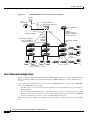
Small to Medium-Sized Network Configuration 1-14
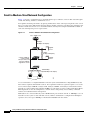
Collapsed Backbone and Switch Cluster Configuration 1-15
Hotel Network Configuration 1-16
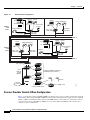
Service-Provider Central-Office Configuration 1-18
Large Campus Configuration 1-20
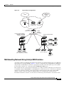
Multidwelling Network Using Catalyst 2950 Switches 1-21
Long-Distance, High-Bandwidth Transport Configuration 1-23
Where to Go Next
1-23
Catalyst 2950 and Catalyst 2955 Switch Software Configuration Guide
OL-10101-02
iii
Contents
CHAPTER
2
Using the Command-Line Interface
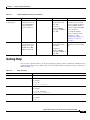
Cisco IOS Command Modes
Getting Help
2-1
2-1
2-3
Abbreviating Commands
2-4
Using no and default Forms of Commands
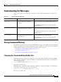
Understanding CLI Messages
2-4
2-5
Using Command History 2-5
Changing the Command History Buffer Size 2-5
Recalling Commands 2-6
Disabling the Command History Feature 2-6
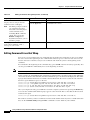
Using Editing Features 2-6
Enabling and Disabling Editing Features 2-6
Editing Commands through Keystrokes 2-7
Editing Command Lines that Wrap 2-8
Searching and Filtering Output of show and more Commands
Accessing the CLI
CHAPTER
3
2-9
2-9
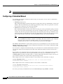
Configuring Catalyst 2955 Switch Alarms
3-1
Understanding Catalyst 2955 Switch Alarms
Global Status Monitoring Alarms 3-2
FCS Error Hysteresis Threshold 3-2
Port Status Monitoring Alarms 3-3
Triggering Alarm Options 3-3
3-1
Configuring Catalyst 2955 Switch Alarms 3-4
Default Catalyst 2955 Switch Alarm Configuration 3-4
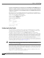
Configuring the Power Supply Alarm 3-5
Setting the Power Mode 3-5
Setting the Power Supply Alarm Options 3-5
Configuring the Switch Temperature Alarms 3-6
Setting a Secondary Temperature Threshold for the Switch
Associating the Temperature Alarms to a Relay 3-7
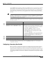
Configuring the FCS Bit Error Rate Alarm 3-7
Setting the FCS Error Threshold 3-8
Setting the FCS Error Hysteresis Threshold 3-8
3-6
Catalyst 2950 and Catalyst 2955 Switch Software Configuration Guide
iv
OL-10101-02
Contents
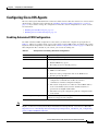
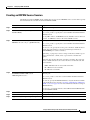
Configuring Alarm Profiles 3-9
Creating or Modifying an Alarm Profile 3-9
Attaching an Alarm Profile to a Specific Port
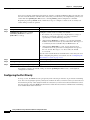
Enabling SNMP Traps 3-11
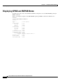
Displaying Catalyst 2955 Switch Alarms Status
CHAPTER
4
3-10
3-11
Assigning the Switch IP Address and Default Gateway
Understanding the Boot Process
4-1
4-1
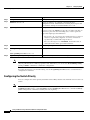
Assigning Switch Information 4-2
Default Switch Information 4-3
Understanding DHCP-Based Autoconfiguration 4-3
DHCP Client Request Process 4-4
Configuring DHCP-Based Autoconfiguration 4-5
DHCP Server Configuration Guidelines 4-5
Configuring the TFTP Server 4-6
Configuring the DNS 4-7
Configuring the Relay Device 4-7
Obtaining Configuration Files 4-8
Example Configuration 4-9
Understanding DHCP-Based Autoconfiguration with a Saved Configuration 4-10
Limitations and Restrictions 4-10
Configuring DHCP-Based Autoconfiguration with a saved configuration 4-11
Manually Assigning IP Information 4-12
Checking and Saving the Running Configuration
4-12
Modifying the Startup Configuration 4-13
Default Boot Configuration 4-13
Automatically Downloading a Configuration File 4-13
Specifying the Filename to Read and Write the System Configuration
Booting Manually 4-14
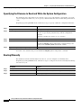
Booting a Specific Software Image 4-15
Controlling Environment Variables 4-16
4-14
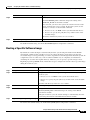
Scheduling a Reload of the Software Image 4-17
Configuring a Scheduled Reload 4-18
Displaying Scheduled Reload Information 4-19
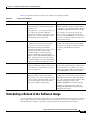
CHAPTER
5
Configuring Cisco IOS CNS Agents
5-1
Understanding Cisco Configuration Engine Software
Configuration Service 5-2
5-1
Catalyst 2950 and Catalyst 2955 Switch Software Configuration Guide
OL-10101-02
v
Contents
Event Service 5-3
NameSpace Mapper 5-3
What You Should Know About the CNS IDs and Device Hostnames
ConfigID 5-4
DeviceID 5-4
Hostname and DeviceID 5-4
Using Hostname, DeviceID, and ConfigID 5-5
Understanding Cisco IOS Agents 5-5
Initial Configuration 5-5
Incremental (Partial) Configuration
Synchronized Configuration 5-6
5-3
5-6
Configuring Cisco IOS Agents 5-7
Enabling Automated CNS Configuration 5-7
Enabling the CNS Event Agent 5-8
Enabling the Cisco IOS CNS Agent 5-9
Enabling an Initial Configuration 5-9
Enabling a Partial Configuration 5-11
Displaying CNS Configuration
CHAPTER
6
Clustering Switches
5-12
6-1
Understanding Switch Clusters 6-1
Cluster Command Switch Characteristics 6-2
Standby Cluster Command Switch Characteristics 6-3
Candidate Switch and Member Switch Characteristics 6-4
Planning a Switch Cluster 6-4
Automatic Discovery of Cluster Candidates and Members 6-5
Discovery Through CDP Hops 6-5
Discovery Through Non-CDP-Capable and Noncluster-Capable Devices
Discovery Through Different VLANs 6-7
Discovery Through Different Management VLANs 6-7
Discovery of Newly Installed Switches 6-8
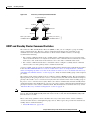
HSRP and Standby Cluster Command Switches 6-9
Virtual IP Addresses 6-10
Other Considerations for Cluster Standby Groups 6-10
Automatic Recovery of Cluster Configuration 6-11
IP Addresses 6-12
Hostnames 6-12
Passwords 6-12
SNMP Community Strings 6-13
6-6
Catalyst 2950 and Catalyst 2955 Switch Software Configuration Guide
vi
OL-10101-02
Contents
TACACS+ and RADIUS 6-13
LRE Profiles
6-13
Catalyst 1900 and Catalyst 2820 CLI Considerations
Using SNMP to Manage Switch Clusters
CHAPTER
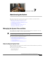
7
Administering the Switch
6-14
6-14
7-1
Managing the System Time and Date 7-1
Understanding the System Clock 7-1
Understanding Network Time Protocol 7-2
Configuring NTP 7-3
Default NTP Configuration 7-4
Configuring NTP Authentication 7-4
Configuring NTP Associations 7-5
Configuring NTP Broadcast Service 7-6
Configuring NTP Access Restrictions 7-8
Configuring the Source IP Address for NTP Packets 7-10
Displaying the NTP Configuration 7-10
Configuring Time and Date Manually 7-11
Setting the System Clock 7-11
Displaying the Time and Date Configuration 7-11
Configuring the Time Zone 7-12
Configuring Summer Time (Daylight Saving Time) 7-12
Configuring a System Name and Prompt 7-14
Default System Name and Prompt Configuration
Configuring a System Name 7-15
Understanding DNS 7-15
Default DNS Configuration 7-16
Setting Up DNS 7-16
Displaying the DNS Configuration 7-17
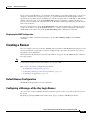
Creating a Banner 7-17
Default Banner Configuration 7-17
Configuring a Message-of-the-Day Login Banner
Configuring a Login Banner 7-18
Managing the MAC Address Table 7-19
Building the Address Table 7-20
MAC Addresses and VLANs 7-20
Default MAC Address Table Configuration
Changing the Address Aging Time 7-21
Removing Dynamic Address Entries 7-21
7-15
7-17
7-20
Catalyst 2950 and Catalyst 2955 Switch Software Configuration Guide
OL-10101-02
vii
Contents
Configuring MAC Address Notification Traps 7-21
Adding and Removing Static Address Entries 7-23
Configuring Unicast MAC Address Filtering 7-24
.Displaying Address Table Entries 7-25
Managing the ARP Table
CHAPTER
8
7-26
Configuring Switch-Based Authentication
8-1
Preventing Unauthorized Access to Your Switch
8-1
Protecting Access to Privileged EXEC Commands 8-2
Default Password and Privilege Level Configuration 8-2
Setting or Changing a Static Enable Password 8-3
Protecting Enable and Enable Secret Passwords with Encryption
Disabling Password Recovery 8-5
Setting a Telnet Password for a Terminal Line 8-6
Configuring Username and Password Pairs 8-7
Configuring Multiple Privilege Levels 8-8
Setting the Privilege Level for a Command 8-8
Changing the Default Privilege Level for Lines 8-9
Logging into and Exiting a Privilege Level 8-10
8-4
Controlling Switch Access with TACACS+ 8-10
Understanding TACACS+ 8-10
TACACS+ Operation 8-12
Configuring TACACS+ 8-12
Default TACACS+ Configuration 8-13
Identifying the TACACS+ Server Host and Setting the Authentication Key 8-13
Configuring TACACS+ Login Authentication 8-14
Configuring TACACS+ Authorization for Privileged EXEC Access and Network Services
Starting TACACS+ Accounting 8-16
Displaying the TACACS+ Configuration 8-17
Controlling Switch Access with RADIUS
Understanding RADIUS 8-17
RADIUS Operation 8-19
8-16
8-17
Catalyst 2950 and Catalyst 2955 Switch Software Configuration Guide
viii
OL-10101-02
Contents
Configuring RADIUS 8-19
Default RADIUS Configuration 8-20
Identifying the RADIUS Server Host 8-20
Configuring RADIUS Login Authentication 8-23
Defining AAA Server Groups 8-25
Configuring RADIUS Authorization for User Privileged Access and Network Services 8-27
Starting RADIUS Accounting 8-28
Configuring Settings for All RADIUS Servers 8-28
Configuring the Switch to Use Vendor-Specific RADIUS Attributes 8-29
Configuring the Switch for Vendor-Proprietary RADIUS Server Communication 8-30
Displaying the RADIUS Configuration 8-31
Configuring the Switch for Local Authentication and Authorization
Configuring the Switch for Secure Shell 8-33
Understanding SSH 8-33
SSH Servers, Integrated Clients, and Supported Versions
Limitations 8-34
Configuring SSH 8-34
Configuration Guidelines 8-34
Cryptographic Software Image Guidelines 8-35
Setting Up the Switch to Run SSH 8-35
Configuring the SSH Server 8-36
Displaying the SSH Configuration and Status 8-37
CHAPTER
9
Configuring IEEE 802.1x Port-Based Authentication
8-32
8-33
9-1
Understanding IEEE 802.1x Port-Based Authentication 9-1
Device Roles 9-2
Authentication Initiation and Message Exchange 9-3
Ports in Authorized and Unauthorized States 9-4
IEEE 802.1x Host Mode 9-5
IEEE 802.1x Accounting 9-6
IEEE 802.1x Accounting Attribute-Value Pairs 9-6
Using IEEE 802.1x Authentication with VLAN Assignment 9-7
Using IEEE 802.1x Authentication with Guest VLAN 9-8
Using IEEE 802.1x Authentication with Restricted VLAN 9-9
Using IEEE 802.1x Authentication with Voice VLAN Ports 9-10
Using IEEE 802.1x Authentication with Port Security 9-10
Using IEEE 802.1x Authentication with Wake-on-LAN 9-11
Network Admission Control Layer 2 IEEE 802.1x Validation 9-11
Catalyst 2950 and Catalyst 2955 Switch Software Configuration Guide
OL-10101-02
ix
Contents
Configuring IEEE 802.1x Authentication 9-12
Default IEEE 802.1x Authentication Configuration 9-12
IEEE 802.1x Authentication Configuration Guidelines 9-13
IEEE 802.1x Authentication 9-14
VLAN Assignment, Guest VLAN, and Restricted VLAN 9-14
Upgrading from a Previous Software Release 9-15
Configuring IEEE 802.1x Authentication 9-15
Configuring the Switch-to-RADIUS-Server Communication 9-17
Configuring the Host Mode 9-18
Enabling Periodic Re-Authentication 9-19
Manually Re-Authenticating a Client Connected to a Port 9-19
Changing the Quiet Period 9-20
Changing the Switch-to-Client Retransmission Time 9-20
Setting the Switch-to-Client Frame-Retransmission Number 9-21
Configuring IEEE 802.1x Accounting 9-22
Configuring a Guest VLAN 9-23
Configuring a Restricted VLAN 9-24
Configuring IEEE 802.1x Authentication with WoL 9-26
Configuring NAC Layer 2 IEEE 802.1x Validation 9-27
Resetting the IEEE 802.1x Configuration to the Default Values 9-28
Displaying IEEE 802.1x Statistics and Status
CHAPTER
10
Configuring Interface Characteristics
9-28
10-1
Understanding Interface Types 10-1
Access Ports 10-2
Trunk Ports 10-2
Port-Based VLANs 10-3
EtherChannel Port Groups 10-3
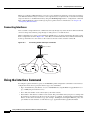
Connecting Interfaces 10-4
Using the Interface Command 10-4
Procedures for Configuring Interfaces 10-5
Configuring a Range of Interfaces 10-5
Configuring and Using Interface-Range Macros
10-7
Configuring Ethernet Interfaces 10-8
Default Ethernet Interface Configuration 10-9
Configuring Interface Speed and Duplex Mode 10-10
Configuration Guidelines 10-10
Setting the Interface Speed and Duplex Parameters on a Non-LRE Switch Port 10-12
Setting the Interface Speed and Duplex Parameters on an LRE Switch Port 10-12
Catalyst 2950 and Catalyst 2955 Switch Software Configuration Guide
x
OL-10101-02
Contents
Configuring Media Types for Gigabit Ethernet Interfaces on LRE Switches 10-13
Configuring IEEE 802.3x Flow Control on IEEE 802.3z Gigabit Ethernet Ports 10-13
Adding a Description for an Interface 10-14
Configuring Loopback Detection 10-15
Monitoring and Maintaining the Interfaces 10-15
Monitoring Interface and Controller Status 10-16
Clearing and Resetting Interfaces and Counters 10-16
Shutting Down and Restarting the Interface 10-17
CHAPTER
11
Configuring Smartports Macros
11-1
Understanding Smartports Macros
11-1
Configuring Smartports Macros 11-2
Default Smartports Macro Configuration 11-2
Smartports Macro Configuration Guidelines 11-3
Creating Smartports Macros 11-4
Applying Smartports Macros 11-5
Applying Cisco-Default Smartports Macros 11-6
Displaying Smartports Macros
CHAPTER
12
Configuring LRE
11-8
12-1
Understanding LRE Features 12-1
Ports on the Catalyst 2950 LRE Switches
LRE Links and LRE Profiles 12-2
LRE Profiles 12-2
LRE Sequences 12-5
CPE Ethernet Links 12-6
LRE Link Monitor 12-7
LRE Message Logging Process 12-7
12-1
Configuring LRE Ports 12-8
Default LRE Configuration 12-8
Environmental Guidelines for LRE Links 12-9
Guidelines for Using LRE Profiles 12-10
CPE Ethernet Link Guidelines 12-10
Guidelines for Configuring Cisco 575 LRE CPEs and 576 LRE 997 CPEs
Guidelines for Configuring Cisco 585 LRE CPEs 12-11
Assigning a Global Profile to All LRE Ports 12-12
Assigning a Profile to a Specific LRE Port 12-12
Assigning a Global Sequence to All LRE Ports 12-13
Assigning a Sequence to a Specific LRE Port 12-13
12-11
Catalyst 2950 and Catalyst 2955 Switch Software Configuration Guide
OL-10101-02
xi
Contents
Using Rate Selection to Automatically Assign Profiles
Precedence 12-15
Profile Locking 12-15
Link Qualification and SNR Margins 12-16
Configuring LRE Link Persistence 12-19
Configuring LRE Link Monitor 12-19
Configuring LRE Interleave 12-19
Configuring Upstream Power Back-Off 12-20
Configuring CPE Toggle 12-21
Configuring Syslog Export 12-22
12-14
Upgrading LRE Switch Firmware 12-23
Configuring for an LRE Upgrade 12-23
Performing an LRE Upgrade 12-24
Global Configuration of LRE Upgrades 12-24
Controller Configuration of LRE Upgrades 12-24
LRE Upgrade Details 12-25
LRE Upgrade Example 12-26
Displaying LRE Status
CHAPTER
13
Configuring STP
12-27
13-1
Understanding Spanning-Tree Features 13-1
STP Overview 13-2
Spanning-Tree Topology and BPDUs 13-2
Bridge ID, Switch Priority, and Extended System ID 13-3
Spanning-Tree Interface States 13-4
Blocking State 13-5
Listening State 13-6
Learning State 13-6
Forwarding State 13-6
Disabled State 13-6
How a Switch or Port Becomes the Root Switch or Root Port 13-7
Spanning Tree and Redundant Connectivity 13-7
Spanning-Tree Address Management 13-8
Accelerated Aging to Retain Connectivity 13-8
Spanning-Tree Modes and Protocols 13-9
Supported Spanning-Tree Instances 13-9
Spanning-Tree Interoperability and Backward Compatibility 13-10
STP and IEEE 802.1Q Trunks 13-10
Catalyst 2950 and Catalyst 2955 Switch Software Configuration Guide
xii
OL-10101-02
Contents
Configuring Spanning-Tree Features 13-10
Default Spanning-Tree Configuration 13-11
Spanning-Tree Configuration Guidelines 13-11
Changing the Spanning-Tree Mode 13-12
Disabling Spanning Tree 13-13
Configuring the Root Switch 13-14
Configuring a Secondary Root Switch 13-16
Configuring the Port Priority 13-17
Configuring the Path Cost 13-18
Configuring the Switch Priority of a VLAN 13-19
Configuring Spanning-Tree Timers 13-20
Configuring the Hello Time 13-20
Configuring the Forwarding-Delay Time for a VLAN 13-21
Configuring the Maximum-Aging Time for a VLAN 13-21
Configuring Spanning Tree for Use in a Cascaded Stack
Displaying the Spanning-Tree Status
CHAPTER
14
Configuring MSTP
13-22
13-23
14-1
Understanding MSTP 14-2
Multiple Spanning-Tree Regions 14-2
IST, CIST, and CST 14-2
Operations Within an MST Region 14-3
Operations Between MST Regions 14-3
Hop Count 14-4
Boundary Ports 14-5
Interoperability with IEEE 802.1D STP 14-5
Understanding RSTP 14-6
Port Roles and the Active Topology 14-6
Rapid Convergence 14-7
Synchronization of Port Roles 14-8
Bridge Protocol Data Unit Format and Processing 14-9
Processing Superior BPDU Information 14-10
Processing Inferior BPDU Information 14-10
Topology Changes 14-10
Configuring MSTP Features 14-11
Default MSTP Configuration 14-11
MSTP Configuration Guidelines 14-12
Specifying the MST Region Configuration and Enabling MSTP
14-13
Catalyst 2950 and Catalyst 2955 Switch Software Configuration Guide
OL-10101-02
xiii
Contents
Configuring the Root Switch 14-14
Configuring a Secondary Root Switch 14-15
Configuring the Port Priority 14-16
Configuring the Path Cost 14-17
Configuring the Switch Priority 14-18
Configuring the Hello Time 14-19
Configuring the Forwarding-Delay Time 14-20
Configuring the Maximum-Aging Time 14-20
Configuring the Maximum-Hop Count 14-21
Specifying the Link Type to Ensure Rapid Transitions
Restarting the Protocol Migration Process 14-22
Displaying the MST Configuration and Status
CHAPTER
15
Configuring Optional Spanning-Tree Features
14-21
14-22
15-1
Understanding Optional Spanning-Tree Features 15-1
Understanding Port Fast 15-2
Understanding BPDU Guard 15-2
Understanding BPDU Filtering 15-3
Understanding UplinkFast 15-3
Understanding Cross-Stack UplinkFast 15-5
How CSUF Works 15-6
Events that Cause Fast Convergence 15-7
Limitations 15-8
Connecting the Stack Ports 15-8
Understanding BackboneFast 15-9
Understanding EtherChannel Guard 15-11
Understanding Root Guard 15-12
Understanding Loop Guard 15-13
Configuring Optional Spanning-Tree Features 15-13
Default Optional Spanning-Tree Configuration 15-13
Optional Spanning-Tree Configuration Guidelines 15-14
Enabling Port Fast 15-14
Enabling BPDU Guard 15-15
Enabling BPDU Filtering 15-16
Enabling UplinkFast for Use with Redundant Links 15-17
Enabling Cross-Stack UplinkFast 15-18
Enabling BackboneFast 15-19
Enabling EtherChannel Guard 15-19
Catalyst 2950 and Catalyst 2955 Switch Software Configuration Guide
xiv
OL-10101-02
Contents
Enabling Root Guard
Enabling Loop Guard
15-20
15-20
Displaying the Spanning-Tree Status
CHAPTER
16
Configuring VLANs
15-21
16-1
Understanding VLANs 16-1
Supported VLANs 16-2
VLAN Port Membership Modes
16-3
Configuring Normal-Range VLANs 16-4
Token Ring VLANs 16-5
Normal-Range VLAN Configuration Guidelines 16-5
VLAN Configuration Mode Options 16-6
VLAN Configuration in config-vlan Mode 16-6
VLAN Configuration in VLAN Configuration Mode
Saving VLAN Configuration 16-6
Default Ethernet VLAN Configuration 16-7
Creating or Modifying an Ethernet VLAN 16-8
Deleting a VLAN 16-9
Assigning Static-Access Ports to a VLAN 16-10
Configuring Extended-Range VLANs 16-11
Default VLAN Configuration 16-11
Extended-Range VLAN Configuration Guidelines
Creating an Extended-Range VLAN 16-12
Displaying VLANs
16-6
16-11
16-13
Configuring VLAN Trunks 16-13
Trunking Overview 16-14
IEEE 802.1Q Configuration Considerations 16-15
Default Layer 2 Ethernet Interface VLAN Configuration 16-16
Configuring an Ethernet Interface as a Trunk Port 16-16
Interaction with Other Features 16-16
Configuring a Trunk Port 16-17
Defining the Allowed VLANs on a Trunk 16-18
Changing the Pruning-Eligible List 16-19
Configuring the Native VLAN for Untagged Traffic 16-19
Load Sharing Using STP 16-20
Load Sharing Using STP Port Priorities 16-20
Load Sharing Using STP Path Cost 16-22
Catalyst 2950 and Catalyst 2955 Switch Software Configuration Guide
OL-10101-02
xv
Contents
Configuring VMPS 16-23
Understanding VMPS 16-23
Dynamic Port VLAN Membership 16-24
VMPS Database Configuration File 16-24
Default VMPS Client Configuration 16-25
VMPS Configuration Guidelines 16-25
Configuring the VMPS Client 16-26
Entering the IP Address of the VMPS 16-26
Configuring Dynamic Access Ports on VMPS Clients 16-26
Reconfirming VLAN Memberships 16-27
Changing the Reconfirmation Interval 16-27
Changing the Retry Count 16-28
Monitoring the VMPS 16-28
Troubleshooting Dynamic Port VLAN Membership 16-29
VMPS Configuration Example 16-29
CHAPTER
17
Configuring VTP
17-1
Understanding VTP 17-1
The VTP Domain 17-2
VTP Modes 17-2
VTP Advertisements 17-3
VTP Version 2 17-4
VTP Pruning 17-4
Configuring VTP 17-6
Default VTP Configuration 17-6
VTP Configuration Options 17-6
VTP Configuration in Global Configuration Mode 17-7
VTP Configuration in VLAN Configuration Mode 17-7
VTP Configuration Guidelines 17-8
Domain Names 17-8
Passwords 17-8
Upgrading from Previous Software Releases 17-8
VTP Version 17-9
Configuration Requirements 17-9
Configuring a VTP Server 17-9
Configuring a VTP Client 17-11
Disabling VTP (VTP Transparent Mode) 17-12
Enabling VTP Version 2 17-13
Catalyst 2950 and Catalyst 2955 Switch Software Configuration Guide
xvi
OL-10101-02
Contents
Enabling VTP Pruning 17-14
Adding a VTP Client Switch to a VTP Domain
Monitoring VTP
CHAPTER
18
17-14
17-15
Configuring Voice VLAN
18-1
Understanding Voice VLAN
18-1
Configuring Voice VLAN 18-2
Default Voice VLAN Configuration 18-2
Voice VLAN Configuration Guidelines 18-3
Configuring a Port to Connect to a Cisco 7960 IP Phone 18-3
Configuring Ports to Carry Voice Traffic in IEEE 802.1Q Frames 18-4
Configuring Ports to Carry Voice Traffic in IEEE 802.1p Priority-Tagged Frames 18-4
Overriding the CoS Priority of Incoming Data Frames 18-5
Configuring the IP Phone to Trust the CoS Priority of Incoming Data Frames 18-5
Displaying Voice VLAN
CHAPTER
19
18-6
Configuring DHCP Features
19-1
Understanding DHCP Features 19-1
DHCP Server 19-2
DHCP Relay Agent 19-2
DHCP Snooping 19-2
Option-82 Data Insertion 19-3
Configuring DHCP Features 19-5
Default DHCP Configuration 19-5
DHCP Snooping Configuration Guidelines 19-6
Configuring the DHCP Server 19-7
Enabling DHCP Snooping and Option 82 19-7
Displaying DHCP Information
CHAPTER
20
19-8
Configuring IGMP Snooping and MVR
20-1
Understanding IGMP Snooping 20-1
IGMP Versions 20-2
Joining a Multicast Group 20-3
Leaving a Multicast Group 20-4
Immediate-Leave Processing 20-5
IGMP Configurable-Leave Timer 20-5
IGMP Report Suppression 20-5
Source-Only Networks 20-6
Catalyst 2950 and Catalyst 2955 Switch Software Configuration Guide
OL-10101-02
xvii
Contents
Configuring IGMP Snooping 20-6
Default IGMP Snooping Configuration 20-7
Enabling or Disabling IGMP Snooping 20-7
Setting the Snooping Method 20-8
Configuring a Multicast Router Port 20-9
Configuring a Host Statically to Join a Group 20-9
Enabling IGMP Immediate-Leave Processing 20-10
Configuring the IGMP Leave Timer 20-10
Disabling IGMP Report Suppression 20-11
Disabling IP Multicast-Source-Only Learning 20-12
Configuring the Aging Time 20-13
Displaying IGMP Snooping Information
20-13
Understanding Multicast VLAN Registration 20-14
Using MVR in a Multicast Television Application
Configuring MVR 20-17
Default MVR Configuration 20-17
MVR Configuration Guidelines and Limitations
Configuring MVR Global Parameters 20-18
Configuring MVR Interfaces 20-19
Displaying MVR Information
20-15
20-17
20-20
Configuring IGMP Filtering and Throttling 20-21
Default IGMP Filtering and Throttling Configuration 20-21
Configuring IGMP Profiles 20-22
Applying IGMP Profiles 20-23
Setting the Maximum Number of IGMP Groups 20-24
Configuring the IGMP Throttling Action 20-24
Displaying IGMP Filtering and Throttling Configuration
CHAPTER
21
Configuring Port-Based Traffic Control
21-1
Configuring Storm Control 21-1
Understanding Storm Control 21-1
Default Storm Control Configuration 21-2
Configuring Storm Control and Threshold Levels
Configuring Protected Ports
20-25
21-2
21-4
Catalyst 2950 and Catalyst 2955 Switch Software Configuration Guide
xviii
OL-10101-02
Contents
Configuring Port Blocking 21-5
Blocking Flooded Traffic on an Interface 21-5
Resuming Normal Forwarding on a Port 21-6
Configuring Port Security 21-6
Understanding Port Security 21-6
Secure MAC Addresses 21-6
Security Violations 21-7
Default Port Security Configuration 21-8
Port Security Configuration Guidelines 21-8
Enabling and Configuring Port Security 21-9
Enabling and Configuring Port Security Aging 21-11
Displaying Port-Based Traffic Control Settings
CHAPTER
22
Configuring UDLD
21-13
22-1
Understanding UDLD 22-1
Modes of Operation 22-1
Methods to Detect Unidirectional Links
22-2
Configuring UDLD 22-3
Default UDLD Configuration 22-4
Configuration Guidelines 22-4
Enabling UDLD Globally 22-5
Enabling UDLD on an Interface 22-5
Resetting an Interface Shut Down by UDLD
Displaying UDLD Status
CHAPTER
23
Configuring CDP
22-6
22-7
23-1
Understanding CDP
23-1
Configuring CDP 23-2
Default CDP Configuration 23-2
Configuring the CDP Characteristics 23-2
Disabling and Enabling CDP 23-3
Disabling and Enabling CDP on an Interface
Monitoring and Maintaining CDP
23-4
23-4
Catalyst 2950 and Catalyst 2955 Switch Software Configuration Guide
OL-10101-02
xix
Contents
CHAPTER
24
Configuring SPAN and RSPAN
24-1
Understanding SPAN and RSPAN 24-1
SPAN and RSPAN Concepts and Terminology 24-3
SPAN Session 24-3
Traffic Types 24-3
Source Port 24-4
Destination Port 24-4
Reflector Port 24-5
SPAN Traffic 24-5
SPAN and RSPAN Interaction with Other Features 24-5
SPAN and RSPAN Session Limits 24-6
Default SPAN and RSPAN Configuration 24-7
Configuring SPAN 24-7
SPAN Configuration Guidelines 24-7
Creating a SPAN Session and Specifying Ports to Monitor 24-8
Creating a SPAN Session and Enabling Ingress Traffic 24-9
Removing Ports from a SPAN Session 24-10
Configuring RSPAN 24-11
RSPAN Configuration Guidelines 24-11
Configuring a VLAN as an RSPAN VLAN 24-12
Creating an RSPAN Source Session 24-13
Creating an RSPAN Destination Session 24-14
Removing Ports from an RSPAN Session 24-15
Displaying SPAN and RSPAN Status
CHAPTER
25
Configuring RMON
24-16
25-1
Understanding RMON
25-1
Configuring RMON 25-2
Default RMON Configuration 25-3
Configuring RMON Alarms and Events 25-3
Configuring RMON Collection on an Interface
Displaying RMON Status
CHAPTER
26
25-4
25-6
Configuring System Message Logging
26-1
Understanding System Message Logging
26-1
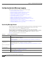
Configuring System Message Logging 26-2
System Log Message Format 26-2
Default System Message Logging Configuration
26-3
Catalyst 2950 and Catalyst 2955 Switch Software Configuration Guide
xx
OL-10101-02
Contents
Disabling and Enabling Message Logging 26-3
Setting the Message Display Destination Device 26-4
Synchronizing Log Messages 26-5
Enabling and Disabling Timestamps on Log Messages 26-6
Enabling and Disabling Sequence Numbers in Log Messages 26-7
Defining the Message Severity Level 26-8
Limiting Syslog Messages Sent to the History Table and to SNMP 26-9
Configuring UNIX Syslog Servers 26-10
Logging Messages to a UNIX Syslog Daemon 26-10
Configuring the UNIX System Logging Facility 26-11
Displaying the Logging Configuration
CHAPTER
27
Configuring SNMP
26-12
27-1
Understanding SNMP 27-1
SNMP Versions 27-2
SNMP Manager Functions 27-3
SNMP Agent Functions 27-3
SNMP Community Strings 27-4
Using SNMP to Access MIB Variables
SNMP Notifications 27-5
27-4
Configuring SNMP 27-5
Default SNMP Configuration 27-5
SNMP Configuration Guidelines 27-6
Disabling the SNMP Agent 27-7
Configuring Community Strings 27-7
Configuring SNMP Groups and Users 27-9
Configuring SNMP Notifications 27-11
Setting the Agent Contact and Location Information
Limiting TFTP Servers Used Through SNMP 27-15
SNMP Examples 27-15
Displaying SNMP Status
CHAPTER
28
27-14
27-16
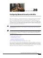
Configuring Network Security with ACLs
28-1
Understanding ACLs 28-2
Handling Fragmented and Unfragmented Traffic 28-3
Understanding Access Control Parameters 28-4
Guidelines for Applying ACLs to Physical Interfaces 28-5
Configuring ACLs 28-6
Unsupported Features
28-7
Catalyst 2950 and Catalyst 2955 Switch Software Configuration Guide
OL-10101-02
xxi
Contents
Creating Standard and Extended IP ACLs 28-7
ACL Numbers 28-7
Creating a Numbered Standard ACL 28-8
Creating a Numbered Extended ACL 28-10
Creating Named Standard and Extended ACLs 28-13
Applying Time Ranges to ACLs 28-14
Including Comments About Entries in ACLs 28-16
Creating Named MAC Extended ACLs 28-17
Creating MAC Access Groups 28-18
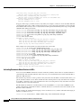
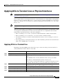
Applying ACLs to Terminal Lines or Physical Interfaces
Applying ACLs to a Terminal Line 28-19
Applying ACLs to a Physical Interface 28-20
28-19
Displaying ACL Information 28-20
Displaying ACLs 28-20
Displaying Access Groups 28-21
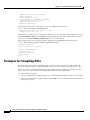
Examples for Compiling ACLs 28-22
Numbered ACL Examples 28-24
Extended ACL Examples 28-24
Named ACL Example 28-24
Commented IP ACL Entry Examples
CHAPTER
29
Configuring QoS
28-24
29-1
Understanding QoS 29-2
Basic QoS Model 29-3
Classification 29-4
Classification Based on QoS ACLs 29-5
Classification Based on Class Maps and Policy Maps
Policing and Marking 29-6
Mapping Tables 29-7
Queueing and Scheduling 29-7
How Class of Service Works 29-7
Port Priority 29-8
Port Scheduling 29-8
Egress CoS Queues 29-8
29-6
Configuring Auto-QoS 29-9
Generated Auto-QoS Configuration 29-9
Effects of Auto-QoS on the Configuration 29-11
Configuration Guidelines 29-12
Upgrading from a Previous Software Release 29-12
Catalyst 2950 and Catalyst 2955 Switch Software Configuration Guide
xxii
OL-10101-02
Contents
Enabling Auto-QoS for VoIP
29-13
Displaying Auto-QoS Information
29-14
Auto-QoS Configuration Example
29-14
Configuring Standard QoS 29-16
Default Standard QoS Configuration 29-17
Configuration Guidelines 29-17
Configuring Classification Using Port Trust States 29-19
Configuring the Trust State on Ports within the QoS Domain 29-19
Configuring the CoS Value for an Interface 29-20
Configuring Trusted Boundary 29-21
Enabling Pass-Through Mode 29-23
Configuring a QoS Policy 29-24
Classifying Traffic by Using ACLs 29-24
Classifying Traffic by Using Class Maps 29-28
Classifying, Policing, and Marking Traffic by Using Policy Maps 29-29
Configuring CoS Maps 29-32
Configuring the CoS-to-DSCP Map 29-32
Configuring the DSCP-to-CoS Map 29-33
Configuring the Egress Queues 29-35
Configuring CoS Priority Queues 29-35
Configuring WRR Priority 29-35
Enabling the Expedite Queue and Configuring WRR Priority 29-36
Displaying Standard QoS Information
29-36
Standard QoS Configuration Examples 29-37
QoS Configuration for the Existing Wiring Closet 29-38
QoS Configuration for the Intelligent Wiring Closet 29-39
CHAPTER
30
Configuring EtherChannels
30-1
Understanding EtherChannels 30-1
Understanding Port-Channel Interfaces 30-3
Understanding the Port Aggregation Protocol and Link Aggregation Protocol
PAgP and LACP Modes 30-4
Physical Learners and Aggregate-Port Learners 30-5
PAgP and LACP Interaction with Other Features 30-5
EtherChannel On Mode 30-6
Understanding Load Balancing and Forwarding Methods 30-6
30-3
Configuring EtherChannels 30-7
Default EtherChannel Configuration 30-8
EtherChannel Configuration Guidelines 30-8
Catalyst 2950 and Catalyst 2955 Switch Software Configuration Guide
OL-10101-02
xxiii
Contents
Configuring Layer 2 EtherChannels 30-9
Configuring EtherChannel Load Balancing 30-11
Configuring the PAgP Learn Method and Priority 30-12
Configuring the LACP Port Priority 30-12
Configuring Hot Standby Ports 30-13
Configuring the LACP System Priority 30-13
Displaying EtherChannel, PAgP, and LACP Status
CHAPTER
31
Troubleshooting
30-14
31-1
Using Recovery Procedures 31-1
Recovering from a Software Failure 31-2
Recovering from Lost or Forgotten Passwords on Non-LRE Catalyst 2950 Switches 31-2
Recovering from Lost or Forgotten Passwords on Catalyst 2950 LRE Switches 31-4
Password Recovery with Password Recovery Enabled 31-5
Procedure with Password Recovery Disabled 31-6
Recovering from Lost or Forgotten Passwords on Catalyst 2955 Switches 31-7
Recovering from a Command Switch Failure 31-10
Replacing a Failed Command Switch with a Cluster Member 31-10
Replacing a Failed Command Switch with Another Switch 31-12
Recovering from Lost Member Connectivity 31-13
Preventing Autonegotiation Mismatches
31-13
GBIC and SFP Module Security and Identification
31-14
Diagnosing Connectivity Problems 31-14
Using Ping 31-14
Understanding Ping 31-14
Executing Ping 31-15
Using Layer 2 Traceroute 31-16
Understanding Layer 2 Traceroute 31-16
Usage Guidelines 31-16
Displaying the Physical Path 31-17
Diagnosing LRE Connection Problems
31-17
Using Debug Commands 31-18
Enabling Debugging on a Specific Feature 31-19
Enabling All-System Diagnostics 31-19
Redirecting Debug and Error Message Output 31-20
Using the debug auto qos Command 31-20
Using the show controllers Commands
Using the crashinfo File
31-21
31-21
Catalyst 2950 and Catalyst 2955 Switch Software Configuration Guide
xxiv
OL-10101-02
Contents
APPENDIX
A
Supported MIBs
MIB List
A-1
A-1
Using FTP to Access the MIB Files
APPENDIX
B
A-3
Working with the Cisco IOS File System, Configuration Files, and Software Images
Working with the Flash File System B-1
Displaying Available File Systems B-2
Setting the Default File System B-3
Displaying Information about Files on a File System B-3
Changing Directories and Displaying the Working Directory
Creating and Removing Directories B-4
Copying Files B-4
Deleting Files B-5
Creating, Displaying, and Extracting tar Files B-5
Creating a tar File B-5
Displaying the Contents of a tar File B-6
Extracting a tar File B-7
Displaying the Contents of a File B-7
B-1
B-3
Working with Configuration Files B-7
Guidelines for Creating and Using Configuration Files B-8
Configuration File Types and Location B-9
Creating a Configuration File By Using a Text Editor B-9
Copying Configuration Files By Using TFTP B-9
Preparing to Download or Upload a Configuration File By Using TFTP B-10
Downloading the Configuration File By Using TFTP B-10
Uploading the Configuration File By Using TFTP B-11
Copying Configuration Files By Using FTP B-11
Preparing to Download or Upload a Configuration File By Using FTP B-12
Downloading a Configuration File By Using FTP B-12
Uploading a Configuration File By Using FTP B-13
Copying Configuration Files By Using RCP B-14
Preparing to Download or Upload a Configuration File By Using RCP B-15
Downloading a Configuration File By Using RCP B-16
Uploading a Configuration File By Using RCP B-17
Clearing Configuration Information B-17
Clearing the Startup Configuration File B-17
Deleting a Stored Configuration File B-18
Working with Software Images B-18
Image Location on the Switch B-18
Catalyst 2950 and Catalyst 2955 Switch Software Configuration Guide
OL-10101-02
xxv
Contents
tar File Format of Images on a Server or .com B-19
Copying Image Files By Using TFTP B-20
Preparing to Download or Upload an Image File By Using TFTP B-20
Downloading an Image File By Using TFTP B-21
Uploading an Image File By Using TFTP B-22
Copying Image Files By Using FTP B-22
Preparing to Download or Upload an Image File By Using FTP B-23
Downloading an Image File By Using FTP B-24
Uploading an Image File By Using FTP B-25
Copying Image Files By Using RCP B-26
Preparing to Download or Upload an Image File By Using RCP B-27
Downloading an Image File By Using RCP B-28
Uploading an Image File By Using RCP B-30
INDEX
Catalyst 2950 and Catalyst 2955 Switch Software Configuration Guide
xxvi
OL-10101-02
Preface
Audience
This guide is for the networking professional managing the Catalyst 2950 and 2955 switches, hereafter
referred to as the switches. Before using this guide, you should have experience working with the Cisco
IOS and be familiar with the concepts and terminology of Ethernet and local area networking.
Purpose
This guide provides the information you need to configure software features on your switch. The
Catalyst 2950 switch is supported by either the standard software image (SI) or the enhanced software image
(EI). The Catalyst 2955 and Catalyst 2950 Long-Reach Ethernet (LRE) switches are supported only by the EI.
The EI provides a richer set of features, including access control lists (ACLs), enhanced quality of service
(QoS) features, extended-range VLANs, Remote Switched Port Analyzer (RSPAN), and unicast MAC
address filtering. The cryptographic SI and EI provide support for the Secure Shell Protocol (SSP). For a list
of switches that support the SI and the EI, see Table 1-1 in Chapter 1, “Overview.”
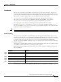
The Catalyst 2955 switch also supports an additional set of features that are described in Chapter 3,
“Configuring Catalyst 2955 Switch Alarms.” The switch has facilities to process alarms related to the
temperature, power supply conditions, and status of the Ethernet ports.
Use this guide with other documents for information about these topics:
•
Requirements—This guide assumes that you have met the hardware and software requirements and
cluster compatibility requirements described in the release notes.
•
Start-up information—This guide assumes that you have assigned switch IP information and
passwords by using the browser setup program described in the switch hardware installation guide.
•
Embedded device manager and Network Assistant graphical user interfaces (GUIs)—This guide
does not provide detailed information on the GUIs. However, the concepts in this guide are
applicable to the GUI user. For information about the device manager, see the switch online help.
For information about Network Assistant, see the Getting Started with Cisco Network Assistant,
available on Cisco.com.
•
Cluster configuration—For information about planning for, creating, and maintaining switch
clusters, see the Getting Started with Cisco Network Assistant, available on Cisco.com. For
information about the clustering-related command-line interface (CLI) commands, see the
command reference for this release.
Catalyst 2950 and Catalyst 2955 Switch Software Configuration Guide
OL-10101-02
xxvii
Preface
•
CLI command information—This guide provides an overview for using the CLI. For complete
syntax and usage information about the commands that have been specifically created or changed
for the switches, see the command reference for this release.
This guide provides procedures for using the commands that have been created or changed for use with
the switch. It does not provide detailed information about these commands. For detailed information
about these commands, see the command reference for this release.
This guide does not repeat the concepts and CLI procedures provided in the standard Cisco IOS
Release 12. documentation. For information about the standard Cisco IOS Release 12. commands, see
the Cisco IOS documentation set available from the Cisco.com home page at Service and Support >
Technical Documents. On the Cisco Product Documentation home page, select Release 12. from the Cisco
IOS Software drop-down list.
This guide does not describe system messages you might encounter or how to install your switch. For
this information, see the system message guide for this release and to the hardware installation guide.
For documentation updates, see the release notes for this release.
Conventions
This publication uses these conventions to convey instructions and information:
Command descriptions use these conventions:
•
Commands and keywords are in boldface text.
•
Arguments for which you supply values are in italic.
•
Square brackets ([ ]) mean optional elements.
•
Braces ({ }) group required choices, and vertical bars ( | ) separate the alternative elements.
•
Braces and vertical bars within square brackets ([{ | }]) mean a required choice within an optional
element.
Interactive examples use these conventions:
•
Terminal sessions and system displays are in screen font.
•
Information you enter is in boldface screen font.
•
Nonprinting characters, such as passwords or tabs, are in angle brackets (< >).
Notes, cautions, and timesavers use these conventions and symbols:
Note
Means reader take note. Notes contain helpful suggestions or references to materials not contained in
this manual.
Caution
Means reader be careful. In this situation, you might do something that could result equipment damage
or loss of data.
Timesaver
Means the following will help you solve a problem. The tips information might not be troubleshooting
or even an action, but could be useful information.
Catalyst 2950 and Catalyst 2955 Switch Software Configuration Guide
xxviii
OL-10101-02
Preface
Related Publications
These documents provide complete information about the switch and are available from this Cisco.com
site:
http://www.cisco.com/en/US/products/ps6738/tsd_products_support_series_home.html
http://www.cisco.com/en/US/products/hw/switches/ps628/tsd_products_support_series_home.html
•
Note
Release Notes for the Catalyst 2950 and Catalyst 2955 Switches
Switch requirements and procedures for initial configurations and software upgrades tend to change and
therefore appear only in the release notes. Before installing, configuring, or upgrading the switch, see
the release notes on Cisco.com for the latest information.
For information about the switch, see these documents:
•
Catalyst 3550, 2955, 2950, and 2940 Switch System Message Guide
•
Catalyst 2950 and Catalyst 2955 Switch Software Configuration Guide
•
Catalyst 2950 and Catalyst 2955 Switch Command Reference
•
Device manager online help (available on the switch)
•
Catalyst 2950 Switch Hardware Installation Guide
•
Catalyst 2950 Switch Getting Started Guide
•
Regulatory Compliance and Safety Information for the Catalyst 2950 Switch
•
Catalyst 2955 Switch Hardware Installation Guide
For information about related products, see these documents:
•
Getting Started with Cisco Network Assistant
•
Release Notes for Cisco Network Assistant
•
Catalyst GigaStack Gigabit Interface Converter Hardware Installation Guide
•
CWDM Passive Optical System Installation Note
•
1000BASE-T Gigabit Interface Converter Installation Notes
•
Cisco Small Form-Factor Pluggable Modules Installation Notes
•
Cisco CWDM GBIC and CWDM SFP Installation Note
•
For information about the NAC features, see the Network Admission Control Software Configuration
Guide
Catalyst 2950 and Catalyst 2955 Switch Software Configuration Guide
OL-10101-02
xxix
Preface
Obtaining Documentation and Submitting a Service Request
For information on obtaining documentation, submitting a service request, and gathering additional
information, see the monthly What’s New in Cisco Product Documentation, which also lists all new and
revised Cisco technical documentation, at:
http://www.cisco.com/en/US/docs/general/whatsnew/whatsnew.html
Subscribe to the What’s New in Cisco Product Documentation as a Really Simple Syndication (RSS) feed
and set content to be delivered directly to your desktop using a reader application. The RSS feeds are a free
service and Cisco currently supports RSS version 2.0.
Catalyst 2950 and Catalyst 2955 Switch Software Configuration Guide
xxx
OL-10101-02
CH A P T E R
1
Overview
This chapter provides these topics about the Catalyst 2950 and Catalyst 2955 switch software:
Note
•
Features, page 1-1
•
Management Options, page 1-9
•
Network Configuration Examples, page 1-11
•
Where to Go Next, page 1-24
In this document, IP refers to IP version 4 (IPv4). Layer 3 IP version 6 (IPv6) packets are treated as
non-IP packets.
Features
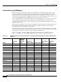
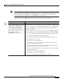
The switch software supports the switches listed in Table 1-1 and in the release notes.
Table 1-1
Switches Supported
Switch
Software Image
Catalyst 2950-12
SI1
Catalyst 2950-24
SI
Catalyst 2950C-24
EI2
Catalyst 2950G-12-EI
EI
Catalyst 2950G-24-EI
EI
Catalyst 2950G-24-EI-DC
EI
Catalyst 2950G-48-EI
EI
Catalyst 2950ST-8 LRE
EI
Catalyst 2950ST-24 LRE
EI
Catalyst 2950ST-24 LRE 997
EI
Catalyst 2950SX-24
SI
Catalyst 2950SX-48-SI
SI
Catalyst 2950T-24
EI
Catalyst 2950 and Catalyst 2955 Switch Software Configuration Guide
OL-10101-02
1-1
Chapter 1
Overview
Features
Table 1-1
Switches Supported (continued)
Switch
Software Image
Catalyst 2950T-48-SI
SI
Catalyst 2955C-12
EI
Catalyst 2955S-12
EI
Catalyst 2955T-12
EI
1. SI = standard software image
2. EI = enhanced software image
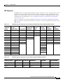
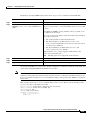
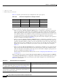
Certain Cisco Long-Reach Ethernet (LRE) customer premises equipment (CPE) devices are not
supported by certain Catalyst 2950 LRE switches. In Table 1-2, Yes means that the CPE is supported by
the switch; No means that the CPE is not supported by the switch.
Table 1-2
LRE Switch and CPE Compatibility Matrix
Catalyst 2950ST-8 LRE
switch
Catalyst 2950ST-24 LRE
switch
Catalyst 2950ST-24 LRE 997
switch
Yes
Yes
No
Cisco 576 LRE 997 No
CPE
No
Yes
Cisco 585 LRE
CPE
Yes
No
LRE Devices
Cisco 575 LRE
CPE
Yes
This section describes the features supported in this release:
Note
Some features require that you have the EI installed on your switch. For a list of the switches that support
the EI, see Table 1-1, or see the release notes for this release.
Ease of Deployment and Ease of Use
The switch ships with these features to make the deployment and use easier:
•
Express Setup for quickly configuring a switch for the first time with basic IP information, contact
information, switch and Telnet passwords, and Simple Network Management Protocol (SNMP)
information through a browser-based program.
•
User-defined Smartports macros for creating custom switch configurations for simplified
deployment across the network.
•
Embedded device manager GUI for configuring and monitoring a single switch through a web
browser. For information about launching the device manager, see the getting started guide. For more
information about the device manager, see the switch online help.
•
Network Assistant application for
– Simplifying and minimizing switch and switch cluster management from anywhere in your
intranet.
Catalyst 2950 and Catalyst 2955 Switch Software Configuration Guide
1-2
OL-10101-02
Chapter 1
Overview
Features
– Accomplishing multiple configuration tasks from a single window without needing to
remember command-line interface (CLI) commands to accomplish specific tasks.
– Interactive guide mode that guides you in configuring complex features such as VLANs, ACLs,
and quality of service (QoS).
– Automated configuration wizards that prompt you to provide only the minimum required
information to configure complex features such as QoS priorities for video traffic, priority
levels for data applications, and security.
– Downloading an image to a switch by using TFTP.
– Applying actions to multiple ports and multiple switches at the same time, such as VLAN and
QoS settings, inventory and statistic reports, link- and switch-level monitoring and
troubleshooting, and multiple switch software upgrades.
– Viewing a topology of interconnected devices to identify existing switch clusters and eligible
switches that can join a cluster and to identify link information between switches.
•
Real-time status monitoring of a switch or multiple switches from the LEDs on the front-panel
images from the device manager and from Network Assistant.
•
Switch clustering technology for
– Unified configuration, monitoring, authentication, and software upgrade of multiple switches
(see the release notes for a list of eligible cluster members).
– Automatic discovery of candidate switches and creation of clusters of up to 16 switches that can
be managed through a single IP address.
– Extended discovery of cluster candidates that are not directly connected to the command switch.
Note
For the Network Assistant software requirements, and for more information about
clustering, see the Getting Started with Cisco Network Assistant, available on Cisco.com.
For clustering requirements, including supported Cisco IOS releases, see the release notes
for this release.
•
Hot Standby Router Protocol (HSRP) for command-switch redundancy. The redundant command
switches used for HSRP must have compatible software releases.
•
DHCP-base autoconfiguration automatically configures a switch at startup with an IP address.
•
Autosensing of speed on the 10/100 and 10/100/1000 ports and autonegotiation of duplex mode on
the 10/100 ports for optimizing bandwidth
•
IEEE 802.3x flow control on Gigabit Ethernet ports operating in full-duplex mode
•
Fast EtherChannel and Gigabit EtherChannel for enhanced fault tolerance and for providing up
to 2 Gbps of bandwidth among switches, routers, and servers
•
Support for frames larger than 1500 bytes. These switches support frame sizes from 1500 to
1530 bytes:
Performance
– Catalyst 2950G-12-EI, 2950G-24-EI, 2950G-24-EI-DC, and 2950G-48-EI switches running
Cisco IOS Release 12.1(6)EA2 or later
– Catalyst 2950 LRE switches
– Catalyst 2955 switches
Catalyst 2950 and Catalyst 2955 Switch Software Configuration Guide
OL-10101-02
1-3
Chapter 1
Overview
Features
•
Port blocking on forwarding unknown unicast and multicast traffic (available only on the
Catalyst LRE switches and on the Catalyst 2950G-12-EI, 2950G-24-EI, 2950G-24-EI-DC,
2950G-48-EI, and 2955 switches)
•
Per-port broadcast storm control for preventing faulty end stations from degrading overall system
performance with broadcast storms
•
Port Aggregation Protocol (PAgP) and Link Aggregation Control Protocol (LACP) for automatic
creation of EtherChannel links
•
Internet Group Management Protocol (IGMP) snooping for IGMP versions 1, 2, and 3 to limit
flooding of IP multicast traffic
•
IGMP report suppression for sending only one IGMP report per multicast router query to the
multicast devices (supported only for IGMPv1 or IGMPv2 queries)
•
Multicast VLAN registration (MVR) to continuously send multicast streams in a multicast VLAN
while isolating the streams from subscriber VLANs for bandwidth and security reasons
•
IGMP filtering for controlling the set of multicast groups to which hosts on a switch port can belong
•
IGMP throttling for configuring the action when the maximum number of entries is in the IGMP
forwarding table
•
Protected port (private VLAN edge port) option for restricting the forwarding of traffic to designated
ports on the same switch
•
Dynamic address learning for enhanced security
•
Cisco Intelligence Engine 2100 (IE2100) Series Cisco Networking Services (CNS) embedded
agents for automating switch management, configuration storage and delivery (available only with
the EI)
•
DHCP-based autoconfiguration for automatically configuring the switch during startup with IP
address information and a configuration file that it receives during DHCP-based autoconfiguration
Manageability
Note
DHCP replaces the Bootstrap Protocol (BOOTP) feature autoconfiguration to ensure
retrieval of configuration files by unicast TFTP messages. BOOTP is available in earlier
software releases for this switch.
•
DHCP server for automatic assignment of IP addresses and other DHCP options to IP hosts
(available only on the Catalyst 2955 switch)
•
DHCP-Based Autoconfiguration with a saved file
•
Address Resolution Protocol (ARP) for identifying a switch through its IP address and its
corresponding MAC address
•
Unicast MAC address filtering to drop packets with specific source or destination MAC addresses
(available only with the EI)
•
Cisco Discovery Protocol (CDP) versions 1 and 2 for network topology discovery and mapping
between the switch and other Cisco devices on the network
•
Network Time Protocol (NTP) for providing a consistent time stamp to all switches from an external
source
•
Directed unicast requests to a TFTP server for obtaining software upgrades from a TFTP server
Catalyst 2950 and Catalyst 2955 Switch Software Configuration Guide
1-4
OL-10101-02
Chapter 1
Overview
Features
•
Default configuration storage in flash memory to ensure that the switch can be connected to a
network and can forward traffic with minimal user intervention
•
In-band management access through the embedded device manager through a Netscape Navigator
or Internet Explorer session or through Network Assistant
•
In-band management access through up to 16 simultaneous Telnet connections for multiple
command-line interface (CLI)-based sessions over the network
•
In-band management access through up to five simultaneous, encrypted Secure Shell (SSH)
connections for multiple CLI-based sessions over the network (only available in the enhanced
cryptographic software image)
•
In-band management access through SNMP versions 1, 2c, and 3 get and set requests
•
Out-of-band management access through the switch console port to a directly-attached terminal or
to a remote terminal through a serial connection and a modem
Note
For additional descriptions of the management interfaces, see the “Management Options”
section on page 1-9.
Redundancy
•
HSRP for command-switch redundancy
•
UniDirectional Link Detection (UDLD) on all Ethernet ports for detecting and disabling
unidirectional links on fiber-optic interfaces caused by incorrect fiber-optic wiring or port faults
•
IEEE 802.1D Spanning Tree Protocol (STP) for redundant backbone connections and loop-free
networks.
– Up to 64 spanning-tree instances supported
– Per-VLAN spanning-tree plus (PVST+) for load balancing across VLANs
– Rapid PVST+ for load balancing across VLANs
– UplinkFast, cross-stack UplinkFast, and BackboneFast for fast convergence after a
spanning-tree topology change and for achieving load balancing among redundant uplinks,
including Gigabit uplinks and cross-stack Gigabit uplinks
•
IEEE 802.1s Multiple Spanning Tree Protocol (MSTP) for grouping VLANs into a spanning-tree
instance and for providing multiple forwarding paths for data traffic and load balancing and rapid
per-VLAN Spanning-Tree plus (rapid-PVST+), based on the IEEE 802.1w Rapid Spanning Tree
Protocol (RSTP) for rapid convergence of the spanning tree by immediately transitioning root and
designated ports to the forwarding state
•
Optional spanning-tree features available in the PVST+, rapid PVST+, and MSTP modes:
– Port Fast for eliminating the forwarding delay by enabling a port to immediately transition from
the blocking state to the forwarding state
– BPDU guard for shutting down Port Fast-enabled ports that receive BPDUs
– BPDU filtering for preventing a Port Fast-enabled port from sending or receiving BPDUs
– Root guard for preventing switches outside the network core from becoming the spanning-tree
root
– Loop guard for preventing alternate or root ports from becoming designated ports because of a
failure that leads to a unidirectional link
Catalyst 2950 and Catalyst 2955 Switch Software Configuration Guide
OL-10101-02
1-5
Chapter 1
Overview
Features
VLAN Support
•
The switches support 250 port-based VLANs for assigning users to VLANs associated with
appropriate network resources, traffic patterns, and bandwidth
Note
The Catalyst 2950-12, Catalyst 2950-24, Catalyst 2950SX-24, Catalyst 2950SX-48-SI, and
Catalyst 2950T-48-SI switches support only 128 port-based VLANs.
•
The switch supports up to 4094 VLAN IDs to allow service provider networks to support the number
of VLANs allowed by the IEEE 802.1Q standard
•
IEEE 802.1Q trunking protocol on all ports for network moves, adds, and changes; management and
control of broadcast and multicast traffic; and network security by establishing VLAN groups for
high-security users and network resources
•
VLAN Membership Policy Server (VMPS) for dynamic VLAN membership
•
VLAN Trunking Protocol (VTP) pruning for reducing network traffic by restricting flooded traffic
to links destined for stations receiving the traffic
•
Dynamic Trunking Protocol (DTP) for negotiating trunking on a link between two devices and for
negotiating the type of trunking encapsulation (IEEE 802.1Q) to be used
•
Voice VLAN for creating subnets for voice traffic from Cisco IP Phones
•
VLAN 1 minimization to reduce the risk of spanning-tree loops or storms by allowing VLAN 1 to
be disabled on any individual VLAN trunk link. With this feature enabled, no user traffic is sent or
received. The switch CPU continues to send and receive control protocol frames.
•
Bridge protocol data unit (BPDU) guard for shutting down a Port Fast-configured port when an
invalid configuration occurs
•
Protected port option for restricting the forwarding of traffic to designated ports on the same switch
•
Password-protected access (read-only and read-write access) to management interfaces (device
manager, Network Assistant, and CLI) for protection against unauthorized configuration changes
•
Port security option for limiting and identifying MAC addresses of the stations allowed to access
the port
•
Port security aging to set the aging time for secure addresses on a port
•
DHCP snooping to filter untrusted DHCP messages between untrusted hosts and DHCP servers
(available only with the EI)
•
Multilevel security for a choice of security level, notification, and resulting actions
•
MAC-based port-level security for restricting the use of a switch port to a specific group of source
addresses and preventing switch access from unauthorized stations
•
TACACS+, a proprietary feature for managing network security through a TACACS server
•
IEEE 802.1x port-based authentication to prevent unauthorized devices from gaining access to the
network
•
IEEE 802.1x accounting to track network usage
Security
Catalyst 2950 and Catalyst 2955 Switch Software Configuration Guide
1-6
OL-10101-02
Chapter 1
Overview
Features
•
IEEE 802.1x with wake-on-LAN to allow dormant PCs to be powered on based on the receipt of a
specific Ethernet frame
•
IEEE 802.1x with restricted VLAN to provide limited services to users who are IEEE 802.1x
compliant, but do not have the credentials to authenticate via the standard IEEE 802.1x processes.
•
Network Admission Control (NAC) Layer 2 IEEE 802.1x validation of the antivirus condition or
posture of endpoint systems or clients before granting the devices network access.
For information about configuring NAC Layer 2 IEEE 802.1x validation, see the “Configuring NAC
Layer 2 IEEE 802.1x Validation” section on page 9-27.
•
Standard and extended IP access control lists (ACLs) for defining security policies (available only
with the EI)
Quality of Service and Class of Service
•
Automatic quality of service (auto-QoS) to simplify the deployment of existing QoS features by
classifying traffic and configuring egress queues (only available in the EI)
•
Classification
– IEEE 802.1p class of service (CoS) with four priority queues on the switch 10/100 and LRE
ports and eight priority queues on the Gigabit ports for prioritizing mission-critical and
time-sensitive traffic from data, voice, and telephony applications
– IP Differentiated Services Code Point (IP DSCP) and CoS marking priorities on a per-port basis
for protecting the performance of mission-critical applications (only available with the EI)
– Flow-based packet classification (classification based on information in the MAC, IP, and
TCP/UDP headers) for high-performance quality of service at the network edge, allowing for
differentiated service levels for different types of network traffic and for prioritizing
mission-critical traffic in the network (only available in the EI)
– Support for IEEE 802.1p CoS scheduling for classification and preferential treatment of
high-priority voice traffic
– Trusted boundary (detect the presence of a Cisco IP Phone, trust the CoS value received, and
ensure port security. If the IP phone is not detected, disable the trusted setting on the port and
prevent misuse of a high-priority queue.)
•
Policing
– Traffic-policing policies on the switch port for allocating the amount of the port bandwidth to
a specific traffic flow
– Policing traffic flows to restrict specific applications or traffic flows to metered, predefined
rates
– Up to 60 policers on ingress Gigabit-capable Ethernet ports
Up to six policers on ingress 10/100 ports
Granularity of 1 Mbps on 10/100 ports and 8 Mbps on 10/100/1000 ports
– Out-of-profile markdown for packets that exceed bandwidth utilization limits
Note
•
Policing is available only in the EI.
Egress Policing and Scheduling of Egress Queues—Four egress queues on all switch ports. Support
for strict priority and weighted round-robin (WRR) CoS policies
Catalyst 2950 and Catalyst 2955 Switch Software Configuration Guide
OL-10101-02
1-7
Chapter 1
Overview
Features
Monitoring
•
Switch LEDs that show port and switch status
•
Switched Port Analyzer (SPAN) and Remote SPAN (RSPAN) for traffic monitoring on any port or
VLAN
Note
RSPAN is available only in the EI.
•
SPAN support of Intrusion Detection Systems (IDSs) to monitor, repel, and report network security
violations
•
Four groups (history, statistics, alarms, and events) of embedded remote monitoring (RMON) agents
for network monitoring and traffic analysis
•
MAC address notification for tracking the MAC addresses that the switch has learned or removed
•
Syslog facility for logging system messages about authentication or authorization errors, resource
issues, and time-out events
•
Layer 2 traceroute to identify the physical path that a packet takes from a source device to a
destination device
•
Facilities for processing alarms related to temperature, power-supply conditions, and the status of
the Ethernet ports (available only on the Catalyst 2955 switch)
LRE Features (available only on Catalyst 2950 LRE switches)
•
Data, voice, and video transmission through categorized and noncategorized unshielded twisted-pair
cable (Category 1, 2, and 3 structured and unstructured cable, such as existing telephone lines) in
multi-unit, multidwelling, and multitenant buildings
•
Up to 15 Mbps of bandwidth to remote Ethernet devices at distances of up to 4921 feet
(1500 meters) on each switch LRE port
•
Compliance with American National Standards Institute (ANSI) and European Telecommunication
Standards Institute (ETSI) standards for spectral-mode compatibility with asymmetric digital
subscriber line (ADSL), Integrated Services Digital Network (ISDN), and digital telephone
networks
•
Configuration and monitoring of connections between:
– Switch LRE ports and the Ethernet ports on remote LRE customer premises equipment (CPE)
devices, such as the Cisco 575 LRE CPE or the Cisco 585 LRE CPE
– CPE Ethernet ports and remote Ethernet devices, such as a PC
•
Support for connecting to the public switched telephone network (PSTN) through plain old
telephone service (POTS) splitters such as the Cisco LRE 48 POTS Splitter
•
Support for the rate selection, a utility that allows for automatic selection of transmission rates
through sequences
•
Support for Reed-Solomon error correction
•
Support for a protected port on Cisco 585 CPE devices
•
Support for small form-factor pluggable (SFP) modules instead of Gigabit Interface Converter
(GBIC) modules
Catalyst 2950 and Catalyst 2955 Switch Software Configuration Guide
1-8
OL-10101-02
Chapter 1
Overview
Management Options
•
Support for configuring the interleave delay feature
•
Support for DC-input power and compliance with the VDSL 997 band plan on Catalyst 2950ST-24
LRE 997 switches
•
Upstream power back-off mechanism for normalization of the upstream receive power levels by
requiring the CPE devices on shorter lines to transmit at a lower power level than the CPEs on longer
lines
•
Support for sending LRE debugging messages to the LRE message logging process and to the
system message logging process
Management Options
The switch is designed for plug-and-play operation: you only need to assign basic IP information to the
switch and connect it to the other devices in your network. If you have specific network needs, you can
configure and monitor the switch—on an individual basis or as part of a switch cluster—through its
various management interfaces.
Note
For information about assigning an IP address by using the browser-based Express Setup program, see
the getting started guide. For information about assigning an IP address by using the CLI-based setup
program, see the hardware installation guide.
This section discusses these topics:
•
Management Interface Options, page 1-9
•
Advantages of Using Network Assistant and Clustering Switches, page 1-10
Management Interface Options
You can configure and monitor individual switches and switch clusters by using these interfaces:
•
An embedded device manager—The device manager is a GUI that is integrated in the software
image. You use it to can configure and to monitor a single switch through a web browser. For more
information about the device manager, see the switch online help.
•
Network Assistant—Network Assistant is a GUI that can be downloaded from Cisco.com. You use
it to manage a single switch or a cluster of switches. For more information about Network Assistant,
see the Getting Started with Cisco Network Assistant, available on Cisco.com.
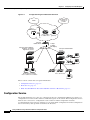
•
CLI—The switch Cisco IOS software supports desktop-switching features. You can access the CLI
either by connecting your management station directly to the switch console port or by using Telnet
or SSH from a remote management station.
For more information about the CLI, see Chapter 2, “Using the Command-Line Interface.”
•
IE2100—Cisco Intelligence Engine 2100 Series Configuration Registrar is a network management
device that works with embedded CNS Agents in the switch software. You can automate initial
configurations and configuration updates by generating switch-specific configuration changes,
sending them to the switch, executing the configuration change, and logging the results.
For more information about IE2100, see Chapter 5, “Configuring Cisco IOS CNS Agents.”
Catalyst 2950 and Catalyst 2955 Switch Software Configuration Guide
OL-10101-02
1-9
Chapter 1
Overview
Management Options
•
SNMP—SNMP provides a means to monitor and control the switch and switch cluster members.
You can manage switch configuration settings, performance, and security and collect statistics by
using SNMP management applications such as CiscoWorks2000 LAN Management Suite (LMS)
and HP OpenView.
You can manage the switch from an SNMP-compatible management station that is running
platforms such as HP OpenView or SunNet Manager. The switch supports a comprehensive set of
MIB extensions and four RMON groups.
For more information about using SNMP, see the Chapter 27, “Configuring SNMP.”
Advantages of Using Network Assistant and Clustering Switches
Using Network Assistant and switch clusters can simplify and minimize your configuration and
monitoring tasks. You can use Cisco switch clustering technology to manage up to 16 interconnected and
supported Catalyst switches through one IP address as if they were a single entity. This can conserve IP
addresses if you have a limited number of them. Network Assistant is the easiest interface to use and
makes switch and switch cluster management accessible to authorized users from any PC on your
network.
By using switch clusters and Network Assistant, you can:
•
Manage and monitor interconnected Catalyst switches (see the release notes for a list of supported
switches), regardless of their geographic proximity and interconnection media, including Ethernet,
Fast Ethernet, Fast EtherChannel, Cisco GigaStack GBIC, Gigabit Ethernet, and Gigabit
EtherChannel connections.
•
Accomplish multiple configuration tasks from a single Network Assistant window without needing
to remember CLI commands to accomplish specific tasks.
•
Apply actions from Network Assistant to multiple ports and multiple switches at the same time to
avoid re-entering the same commands for each individual port or switch. Here are some examples
of globally setting and managing multiple ports and switches:
– Port configuration such as speed and duplex settings
– Port and console port security settings
– NTP, STP, VLAN, and quality of service (QoS) configurations
– Inventory and statistic reporting and link and switch-level monitoring and troubleshooting
– Group software upgrades
•
View a topology of interconnected devices to identify existing switch clusters and eligible switches
that can join a cluster. You can also use the topology to quickly identify link information between
switches.
•
Monitor real-time status of a switch or multiple switches from the LEDs on the front-panel images.
The system, redundant power system (RPS), and port LED colors on the images are similar to those
on the physical LEDs.
•
Use an interactive mode that takes you step-by-step through configuring complex features such as
VLANs, ACLs, and QoS.
•
Use a wizard that prompts you to provide the minimum required information to configure complex
features such as QoS priorities for video traffic, priority levels for data applications, and security.
For more information about Network Assistant and clustering, see the Getting Started with Cisco
Network Assistant, available on Cisco.com.
Catalyst 2950 and Catalyst 2955 Switch Software Configuration Guide
1-10
OL-10101-02
Chapter 1
Overview
Network Configuration Examples
Network Configuration Examples
This section provides network configuration concepts and includes examples of using the switch to
create dedicated network segments and interconnecting the segments through Fast Ethernet and Gigabit
Ethernet connections.
•
“Design Concepts for Using the Switch” section on page 1-11
•
“Small to Medium-Sized Network Configuration” section on page 1-14
•
“Collapsed Backbone and Switch Cluster Configuration” section on page 1-15
•
“Hotel Network Configuration” section on page 1-16
•
“Service-Provider Central-Office Configuration” section on page 1-18
•
“Large Campus Configuration” section on page 1-20
•
“Multidwelling Network Using Catalyst 2950 Switches” section on page 1-21
•
“Long-Distance, High-Bandwidth Transport Configuration” section on page 1-23
Design Concepts for Using the Switch
As your network users compete for network bandwidth, it takes longer to send and receive data. When
you configure your network, consider the bandwidth required by your network users and the relative
priority of the network applications they use.
Table 1-3 describes what can cause network performance to degrade and how you can configure your
network to increase the bandwidth available to your network users.
Table 1-3
Increasing Network Performance
Network Demands
Suggested Design Methods
Too many users on a single network segment
and a growing number of users accessing the
Internet
•
Increased power of new PCs,
workstations, and servers
•
High demand from networked
applications (such as e-mail with large
attached files) and from
bandwidth-intensive applications (such
as multimedia)
•
Create smaller network segments so that fewer users share the
bandwidth, and use VLANs and IP subnets to place the network
resources in the same logical network as the users who access those
resources most.
•
Use full-duplex operation between the switch and its connected
workstations.
•
Connect global resources—such as servers and routers to which network
users require equal access—directly to the Fast Ethernet or Gigabit
Ethernet switch ports so that they have their own Fast Ethernet or Gigabit
Ethernet segment.
•
Use the Fast EtherChannel or Gigabit EtherChannel feature between the
switch and its connected servers and routers.
Bandwidth alone is not the only consideration when designing your network. As your network traffic
profiles evolve, consider providing network services that can support applications such as voice and data
integration and security.
Table 1-4 describes some network demands and how you can meet those demands.
Catalyst 2950 and Catalyst 2955 Switch Software Configuration Guide
OL-10101-02
1-11
Chapter 1
Overview
Network Configuration Examples
Table 1-4
Providing Network Services
Network Demands
Suggested Design Methods
High demand for multimedia support
•
Use IGMP and MVR to efficiently forward multicast traffic.
High demand for protecting mission-critical
applications
•
Use VLANs and protected ports to provide security and port isolation.
•
Use VLAN trunks, cross-stack UplinkFast, and BackboneFast for
traffic-load balancing on the uplink ports so that the uplink port with a
lower relative port cost is selected to carry the VLAN traffic.
An evolving demand for IP telephony
•
Use QoS to prioritize applications such as IP telephony during
congestion and to help control both delay and jitter within the network.
•
Use switches that support at least two queues per port to prioritize voice
and data traffic as either high- or low-priority, based on 802.1p or
802.1Q.
•
Use the Catalyst 2900 LRE XL or Catalyst 2950 LRE switches to
provide up to 15 Mb of IP connectivity over existing infrastructure
(existing telephone lines).
A growing demand for using existing
infrastructure to transport data and voice from
a home or office to the Internet or an intranet at
higher speeds
Figure 1-1 shows configuration examples of using the Catalyst switches to create these networks:
•
Cost-effective wiring closet—A cost-effective way to connect many users to the wiring closet is to
connect up to nine Catalyst 2900 XL, Catalyst 2950, Catalyst 3500 XL, and Catalyst 3550 switches
through GigaStack GBIC connections. When you use a stack of Catalyst 2950G-48 switches, you
can connect up to 432 users. To preserve switch connectivity if one switch in the stack fails, connect
the bottom switch to the top switch to create a GigaStack loopback, and enable cross-stack
UplinkFast on the cross-stack Gigabit uplinks.
You can create backup paths by using Fast Ethernet, Gigabit, Fast EtherChannel, or Gigabit
EtherChannel links. Using Gigabit modules on two of the switches, you can have redundant uplink
connections to a Gigabit backbone switch such as the Catalyst 3550-12G switch. If one of the
redundant connections fails, the other can serve as a backup path. You can configure the stack
members and the Catalyst 3550-12G switch as a switch cluster to manage them through a single IP
address.
•
High-performance workgroup—For users who require high-speed access to network resources, use
Gigabit modules to connect the switches directly to a backbone switch in a star configuration. Each
switch in this configuration provides users with a dedicated 1-Gbps connection to network resources
in the backbone. Compare this with the switches in a GigaStack configuration, where the 1-Gbps
connection is shared among the switches. With the high speed uplink to the distribution server, the
user can efficiently obtain and store data from servers. Using these Gigabit Ethernet modules also
provides flexibility in media and distance options:
– 1000BASE-T GBIC: copper connections of up to 328 feet (100 meters)
– 1000BASE-SX GBIC: fiber connections of up to 1804 feet (550 meters)
– 1000BASE-LX/LH GBIC: fiber connections of up to 32,808 feet (10 kilometers)
– 1000BASE-ZX GBIC: fiber connections of up to 328,084 feet (100 kilometers)
Catalyst 2950 and Catalyst 2955 Switch Software Configuration Guide
1-12
OL-10101-02
Chapter 1
Overview
Network Configuration Examples
– GigaStack GBIC module for creating a 1-Gbps stack configuration of up to nine supported
switches. The GigaStack GBIC supports one full-duplex link (in a point-to-point configuration)
or up to nine half-duplex links (in a stack configuration) to other Gigabit Ethernet devices.
Using the required Cisco proprietary signaling and cabling, the GigaStack GBIC-to-GigaStack
GBIC connection cannot exceed 3 feet (1 meter).
– SFP modules: fiber and copper connections of up to 32,808 feet (10 kilometers) (supported only
on the Catalyst 2950 LRE switches)
•
Redundant Gigabit backbone—Using HSRP, you can create backup paths between
Catalyst 3550-12T-L3 switches. To enhance network reliability and load balancing for different
VLANs and subnets, you can connect the Catalyst 2950 switches, again in a star configuration, to
two backbone switches. If one of the backbone switches fails, the second backbone switch preserves
connectivity between the switches and network resources.
Figure 1-1
Example Configurations
Catalyst 2950 switch
Cost-Effective
Wiring Closet
Catalyst 2900 XL,
Catalyst 2950,
Catalyst 3500 XL,
and Catalyst 3550
GigaStack cluster
Catalyst 3550-12T or
Catalyst 3550-12G switch
Si
Gigabit
server
High-Performance
Workgroup
Catalyst 2900 XL, Catalyst 2950, Catalyst 2955,
Catalyst 3500 XL, and Catalyst 3550 cluster
Catalyst 3550-12T or
Catalyst 3550-12T or
Catalyst 3550-12G switch
Catalyst 3550-12G switch
1-Gbps HSRP
Si
Si
Catalyst 2900 XL, Catalyst 2950, Catalyst 2955,
Catalyst 3500 XL, and Catalyst 3550 cluster
60992
Redundant Gigabit
Backbone
Catalyst 2950 and Catalyst 2955 Switch Software Configuration Guide
OL-10101-02
1-13
Chapter 1
Overview
Network Configuration Examples
Small to Medium-Sized Network Configuration
Figure 1-2 shows a configuration for a network that has up to 250 users. Users in this network require
e-mail, file-sharing, database, and Internet access.
You optimize network performance by placing workstations on the same logical segment as the servers
they access most often. This divides the network into smaller segments (or workgroups) and reduces the
amount of traffic that travels over a network backbone, thereby increasing the bandwidth available to
each user and improving server response time.
Figure 1-2
Small to Medium-Sized Network Configuration
Cisco 2600 router
100 Mbps
(200 Mbps full duplex)
Gigabit
server
1 Gbps
(2 Gbps full duplex)
Catalyst 2900 XL,
Catalyst 2950,
Catalyst 3550, and
Catalyst 3500 XL
GigaStack cluster
Gigabit
server
Single workstations
60993
10/100 Mbps
(20/200 Mbps full duplex)
A network backbone is a high-bandwidth connection (such as Fast Ethernet or Gigabit Ethernet) that
interconnects segments and network resources. It is required if numerous segments require access to the
servers. The Catalyst 2900 XL, Catalyst 2950, Catalyst 3500 XL, and Catalyst 3550 switches in this
network are connected through a GigaStack GBIC on each switch to form a 1-Gbps network backbone.
This GigaStack can also be configured as a switch cluster, with primary and secondary command
switches for redundant cluster management.
Workstations are connected directly to the 10/100 switch ports for their own 10- or 100-Mbps access to
network resources (such as web and mail servers). When a workstation is configured for full-duplex
operation, it receives up to 200 Mbps of dedicated bandwidth from the switch.
Catalyst 2950 and Catalyst 2955 Switch Software Configuration Guide
1-14
OL-10101-02
Chapter 1
Overview
Network Configuration Examples
Servers are connected to the GBIC module ports on the switches, allowing 1-Gbps throughput to users
when needed. When the switch and server ports are configured for full-duplex operation, the links
provide 2 Gbps of bandwidth. For networks that do not require Gigabit performance from a server,
connect the server to a Fast Ethernet or Fast EtherChannel switch port.
Connecting a router to a Fast Ethernet switch port provides multiple, simultaneous access to the Internet
through one line.
Collapsed Backbone and Switch Cluster Configuration
Figure 1-3 shows a configuration for a network of approximately 500 employees. This network uses a
collapsed backbone and switch clusters. A collapsed backbone has high-bandwidth uplinks from all
segments and subnetworks to a single device, such as a Gigabit switch, that serves as a single point for
monitoring and controlling the network. You can use a Catalyst 3550-12T-L3 switch, as shown, or a
Catalyst 3508G XL switch to create a Gigabit backbone. A Catalyst 3550-12T-L3 backbone switch
provides the benefits of inter-VLAN routing and allows the router to focus on WAN access.
The workgroups are created by clustering all the Catalyst switches except the Catalyst 4908G-L3 switch.
Using Network Assistant and Cisco switch clustering technology, you can group the switches into
multiple clusters, as shown, or into a single cluster. You can manage a cluster through the IP address of
its active and standby command switches, regardless of the geographic location of the cluster members.
This network uses VLANs to segment the network logically into well-defined broadcast groups and for
security management. Data and multimedia traffic are configured on the same VLAN. Voice traffic from
the Cisco IP Phones are configured on separate voice VLAN IDs (VVIDs). You can have up to
four VVIDs per wiring closet. If data, multimedia, and voice traffic are assigned to the same VLAN, only
one VLAN can be configured per wiring closet. For any switch port connected to Cisco IP Phones,
802.1p or 802.1Q QoS gives forwarding priority to voice traffic over data traffic.
Grouping servers in a centralized location provides benefits such as security and easier maintenance. The
Gigabit connections to a server farm provide the workgroups full access to the network resources (such
as a call-processing server running Cisco CallManager software, a DHCP server, or an IP/TV multicast
server).
Cisco IP Phones are connected—using standard straight-through, twisted-pair cable with RJ-45
connectors—to the 10/100 inline-power ports on the Catalyst 3550-24PWR switches and to the
10/100 ports on the Catalyst 2950 switches. These multiservice switch ports automatically detect any IP
phones that are connected. Cisco CallManager controls call processing, routing, and IP phone features
and configuration. Users with workstations running Cisco SoftPhone software can place, receive, and
control calls from their PCs. Using Cisco IP Phones, Cisco CallManager software, and Cisco SoftPhone
software integrates telephony and IP networks, and the IP network supports both voice and data.
Each 10/100 inline-power port on the Catalyst 3550-24PWR switches provides –48 VDC power to the
Cisco IP Phone. The IP phone can receive redundant power when it is also connected to an AC power
source. IP phones not connected to the Catalyst 3550-24PWR switches receive power from an AC power
source.
Catalyst 2950 and Catalyst 2955 Switch Software Configuration Guide
OL-10101-02
1-15
Chapter 1
Overview
Network Configuration Examples
Figure 1-3
Collapsed Backbone and Switch Cluster Configuration
Gigabit
servers
Cisco
CallManager
Catalyst 3550-12T or
Catalyst 3550-12G switch
Cisco 2600 router
Si
200 Mbps
Fast EtherChannel
(400-Mbps full-duplex
Fast EtherChannel)
1 Gbps
(2 Gbps full duplex)
Catalyst 2950, 2900 XL,
3550, and 3500 XL
GigaStack cluster
Catalyst
2950,
2900 XL,
3550, and
3500 XL
GigaStack cluster
Catalyst 3550-24PWR
cluster
IP
IP
IP
Workstations running
Cisco SoftPhone software
IP
Cisco IP Phones
IP
60994
Cisco
IP Phones
Hotel Network Configuration
Figure 1-4 shows Catalyst 2950ST-8 LRE and 2950ST-24 LRE switches in a hotel network environment
with approximately 200 rooms. This network includes a PBX switchboard, a router, and high-speed
servers.
Connected to the telephone line in each hotel room is an LRE CPE device, such as a Cisco LRE CPE
device. The LRE CPE device provides:
•
Two RJ-11 ports, one for connecting to the telephone jack on the wall and one for connecting to a
POTS telephone.
•
One or more RJ-45 Ethernet ports for connecting to devices such as a customer’s laptop, the room
IP phone, the television set-top box, or a room environmental control device. A Cisco 575 LRE CPE
provides one Ethernet connection; a Cisco 585 LRE CPE provides four.
When connected to the CPE device, the Ethernet devices and room telephone share the same telephone
line.
Catalyst 2950 and Catalyst 2955 Switch Software Configuration Guide
1-16
OL-10101-02
Chapter 1
Overview
Network Configuration Examples
Note
All telephones not directly connected to the hotel room CPE device require microfilters with a 300-ohm
termination. Microfilters improve voice call quality when voice and data equipment are using the same
telephone line. They also prevent nonfiltered telephone rings and nonfiltered telephone transitions (such
as on-hook to off-hook) from interrupting the Ethernet connection.
Through a patch panel, the telephone line from each room connects to a nonhomologated POTS splitter,
such as the Cisco LRE 48 POTS Splitter. The splitter routes data (high-frequency) and voice
(low-frequency) traffic from the telephone line to a Catalyst 2950 LRE switch and digital private branch
exchange (PBX). The PBX routes voice traffic to the PSTN.
If a PBX is not on-site, a homologated POTS splitter is required to connect directly to the PSTN.
Note
Consult the regulations for connecting to the PSTN in your area.
If a connection to a phone network is not required at all, a splitter is not needed, and the switch can
connect directly to the patch panel.
Note
Cisco LRE products can share lines with analog telephones, Integrated Services Digital Network (ISDN)
telephone network, and PBX switches that use the 0 to 700 kHz frequency range.
Data to and from the room devices (such as e-mail for the laptop and IP multicast traffic for the
television) are transferred through the LRE link, which is established between the CPE RJ-11 wall port
and the LRE port on an LRE switch. The upstream and downstream rates on the LRE link are controlled
by a profile configured on each LRE port. If the LRE switch was connected to the PSTN through a
homologated POTS splitter, all LRE ports would use an ANSI-compliant LRE profile named
LRE-998-15-4.
The Catalyst 2950 LRE switches are cascaded through their 10/100/1000 switch ports. Each switch also
has a 10/100/1000 connection to an aggregation switch, such as a Catalyst 3550-12G switch. The
aggregation switch can connect to these devices:
•
Accounting, billing, and provisioning servers
•
A router that provides Internet access to the premises
You can manage the switches as a switch cluster and through Network Assistant. You can also manage
and monitor the individual CPE devices from the LRE switches to which they are connected. The
Catalyst 2950 LRE switch ports support the same software features as 10/100/1000 switch ports. For
example, you can configure port-based VLANs on the LRE ports to provide individual port security and
protected ports to further prevent unwanted broadcasts within the VLANs.
Catalyst 2950 and Catalyst 2955 Switch Software Configuration Guide
OL-10101-02
1-17
Chapter 1
Overview
Network Configuration Examples
Figure 1-4
Network Hotel Configuration
Set-top
box
IP
phone
Laptop
TV
Rooms
and
users
Laptop
POTS telephones
IP
Environmental
controls
POTS telephone
Required
microfilter
Cisco 575
LRE CPE
Cisco 585
LRE CPE
Required
microfilter
Floor 4
Laptop
POTS telephones
Set-top
box
Laptop
TV
Rooms
and
users
IP
phone
IP
Environmental
controls
Required
microfilter
Cisco 575
LRE CPE
POTS telephone
Required
microfilter
Cisco 585
LRE CPE
Floor 3
Patch panel
Cisco
LRE 48
POTS
splitters
Catalyst 2950ST-8 LRE and
2950ST-24 LRE switches
PSTN
PBX
Catalyst 2950 or
Catalyst 3550 switch
Cisco 2600 router
89514
Servers
Service-Provider Central-Office Configuration
Figure 1-5 shows the Catalyst 2950ST-24 LRE 997 switches in a service-provider central-office network
environment. The Catalyst 2950ST-24 LRE 997 switches have DC-input power supply and are compliant
with the VDSL 997 band plan. The Catalyst 2950 LRE switches are located in a central office and are
connected to the Cisco 576 LRE 997 CPE devices located in different buildings. The switches also
connect to a Cisco 7500 router.
Catalyst 2950 and Catalyst 2955 Switch Software Configuration Guide
1-18
OL-10101-02
Chapter 1
Overview
Network Configuration Examples
You can use a POTS splitter to connect the switches to the CPE devices. The splitter routes data
(high-frequency) to a Catalyst 2950 LRE switch and voice (low-frequency) traffic from the telephone
line to a PSTN.
Connected to the telephone line in each office is an Cisco 576 LRE 997 CPE device. The LRE CPE
device provides:
•
Two RJ-11 ports, one for connecting to the telephone jack on the wall and one for connecting to a
POTS telephone.
•
One RJ-45 Ethernet port for connecting to devices such as a customer’s laptop, the office’s IP phone,
the television set-top box, or a office environmental control device. A Cisco 576 LRE 997 provides
one Ethernet connection.
When connected to the CPE device, the Ethernet devices and office telephone share the same telephone
line.
Note
All telephones not directly connected to the office CPE device require microfilters with a 300-ohm
termination. Microfilters improve voice call quality when voice and data equipment are using the same
telephone line. They also prevent nonfiltered telephone rings and nonfiltered telephone transitions (such
as on-hook to off-hook) from interrupting the Ethernet connection.
Note
Cisco LRE products can share lines with analog telephones and Integrated Services Digital Network
(ISDN) telephone network that use the 0 to 120 kHz frequency range.
Data to and from the office devices (such as e-mail for the laptop and IP multicast traffic for the
television) are transferred through the LRE link, which is established between the CPE RJ-11 wall port
and the LRE port on an LRE switch. The upstream and downstream rates on the LRE link are controlled
by a profile configured on each LRE port.
The Catalyst 2950 LRE switches are cascaded through their 10/100/1000 switch ports. Each switch also
has a 10/100/1000 connection to an aggregation switch, such as a Catalyst 3550-12G switch or
Cisco 7600 router.
You can manage the switches as a switch cluster and through Network Assistant. You can also manage
and monitor the individual CPE devices from the LRE switches to which they are connected. The
Catalyst 2950 LRE switch ports support the same software features as 10/100/1000 switch ports. For
example, you can configure port-based VLANs on the LRE ports to provide individual port security and
protected ports to further prevent unwanted broadcasts within the VLANs.
Catalyst 2950 and Catalyst 2955 Switch Software Configuration Guide
OL-10101-02
1-19
Chapter 1
Overview
Network Configuration Examples
Figure 1-5
Service Provider Central Office Configuration
Copper twisted pair
Central office
Cisco router
7500
Offices and users
Building 1
Laptop
POTS telephones
Building 2
Building 3
POTS
splitter
Catalyst 2950ST-24
LRE 997 switches
(DC-input power)
Cisco 576
LRE 997
Required
microfilter
89380
POTS
splitter
Building 4
Cisco 576 LRE 997 CPE
Large Campus Configuration
Figure 1-6 shows a configuration for a network of more than 1000 users. Because it can aggregate up to
130 Gigabit connections, a Catalyst 6500 multilayer switch is used as the backbone switch.
You can use the workgroup configurations shown in previous examples to create workgroups with
Gigabit uplinks to the Catalyst 6500 switch. For example, you can use switch clusters that have a mix of
Catalyst 2950 and Catalyst 2955 switches.
The Catalyst 6500 switch provides the workgroups with Gigabit access to core resources:
•
Cisco 7000 series router for access to the WAN and the Internet.
•
Server farm that includes a call-processing server running Cisco CallManager software. Cisco
CallManager controls call processing, routing, and IP phone features and configuration.
•
Cisco Access gateway (such as Cisco Access Digital Trunk Gateway or Cisco Access Analog Trunk
Gateway) that connects the IP network to the Public Switched Telephone Network (PSTN) or to
users in an IP telephony network.
Catalyst 2950 and Catalyst 2955 Switch Software Configuration Guide
1-20
OL-10101-02
Chapter 1
Overview
Network Configuration Examples
Figure 1-6
Large Campus Configuration
IP telephony
network or
PSTN
WAN
Cisco
CallManager
Cisco 7200 Cisco access
or 7500 router gateway
Servers
Catalyst
6500 switch
Catalyst 2950, 2900 XL,
3500 XL, and 3550
GigaStack cluster
1 Gbps
(2 Gbps
full duplex)
Catalyst 3550-24PWR
cluster
IP
IP
Cisco IP Phones
IP
IP
Cisco IP Phones
60995
Workstations running
Cisco SoftPhone software
IP
Multidwelling Network Using Catalyst 2950 Switches
A growing segment of residential and commercial customers are requiring high-speed access to Ethernet
metropolitan-area networks (MANs). Figure 1-7 shows a configuration for a Gigabit Ethernet MAN ring
using Catalyst 3550 multilayer switches as aggregation switches in the mini-point-of-presence (POP)
location. These switches are connected through 1000BASE-X GBIC ports.
The resident switches can be Catalyst 2950 switches, providing customers with high-speed connections
to the MAN. Catalyst 2900 LRE XL or 2950 LRE Layer 2-only switches also can be used as residential
switches for customers requiring connectivity through existing telephone lines. The Catalyst LRE
switches can then connect to another residential switch or to an aggregation switch. For more
information about these switches, see the Catalyst 2950 Desktop Switch Hardware Installation Guide.
Catalyst 2950 and Catalyst 2955 Switch Software Configuration Guide
OL-10101-02
1-21
Chapter 1
Overview
Network Configuration Examples
All ports on the residential Catalyst 2950 and 2955 switches (and Catalyst LRE switches if they are
included) are configured as 802.1Q trunks with protected port and STP root guard features enabled. The
protected port feature provides security and isolation between ports on the switch, ensuring that
subscribers cannot view packets destined for other subscribers. STP root guard prevents unauthorized
devices from becoming the STP root switch. All ports have IGMP snooping or CGMP enabled for
multicast traffic management. ACLs on the uplink ports to the aggregating Catalyst 3550 multilayer
switches provide security and bandwidth management.
The aggregating switches and routers provide services such as those described in the previous examples,
“Small to Medium-Sized Network Configuration” and “Large Campus Configuration.”
Figure 1-7
Catalyst 2950 Switches in a MAN Configuration
Cisco 12000
Gigabit switch routers
Catalyst 6500
switches
Catalyst 3550
multilayer
switches
Service
Provider
POP
Si
Si
Si
Si
Si
Si
Si
Mini-POP
Gigabit MAN
Si
Catalyst
switches
Residential
location
Set-top box
Residential
gateway (hub)
Set-top box
50833
TV
PC
TV
Catalyst 2950 and Catalyst 2955 Switch Software Configuration Guide
1-22
OL-10101-02
Chapter 1
Overview
Network Configuration Examples
Long-Distance, High-Bandwidth Transport Configuration
Note
To use the feature described in this section, you must have the EI installed on your switch.
Figure 1-8 shows a configuration for transporting 8 Gigabits of data over a single fiber-optic cable. The
Catalyst switches have Coarse Wave Division Multiplexer (CWDM) fiber-optic GBIC modules installed.
Depending on the CWDM GBIC module, data is sent at wavelengths from 1470 nm to 1610 nm. The
higher the wavelength, the farther the transmission can travel. A common wavelength used for
long-distance transmissions is 1550 nm.
The CWDM GBIC modules connect to CWDM optical add/drop multiplexer (OADM) modules over
distances of up to 393,701 feet (74.5 miles or 120 km). The CWDM OADM modules combine (or
multiplex) the different CWDM wavelengths, allowing them to travel simultaneously on the same
fiber-optic cable. The CWDM OADM modules on the receiving end separate (or demultiplex) the
different wavelengths.
For more information about the CWDM GBIC modules and CWDM OADM modules, see the Cisco
CWDM GBIC and CWDM SFP Installation Note.
Figure 1-8
Long-Distance, High-Bandwidth Transport Configuration
Access layer
Aggregation layer
CWDM
OADM
modules
Eight
1-Gbps
connections
CWDM
OADM
modules
Catalyst 4500
multilayer
switches
95750
8 Gbps
Catalyst switches
Catalyst 2950 and Catalyst 2955 Switch Software Configuration Guide
OL-10101-02
1-23
Chapter 1
Overview
Where to Go Next
Where to Go Next
Before configuring the switch, review these sections for start-up information:
•
Chapter 2, “Using the Command-Line Interface”
•
Chapter 4, “Assigning the Switch IP Address and Default Gateway”
•
Chapter 5, “Configuring Cisco IOS CNS Agents”
Catalyst 2950 and Catalyst 2955 Switch Software Configuration Guide
1-24
OL-10101-02
CH A P T E R
2
Using the Command-Line Interface
This chapter describes the Cisco IOS command-line interface (CLI) that you can use to configure your
Catalyst 2950 and Catalyst 2955. It contains these sections:
•
Cisco IOS Command Modes, page 2-1
•
Getting Help, page 2-3
•
Abbreviating Commands, page 2-4
•
Using no and default Forms of Commands, page 2-4
•
Understanding CLI Messages, page 2-5
•
Using Command History, page 2-5
•
Using Editing Features, page 2-6
•
Searching and Filtering Output of show and more Commands, page 2-9
•
Accessing the CLI, page 2-9
Cisco IOS Command Modes
The user interface is divided into many different modes. The commands available to you depend on
which mode you are currently in. Enter a question mark (?) at the system prompt to obtain a list of
commands available for each command mode.
When you start a session on the switch, you begin in user mode, often called user EXEC mode. Only a
limited subset of the commands are available in user EXEC mode. For example, most of the user EXEC
commands are one-time commands, such as show commands, which show the current configuration
status, and clear commands, which clear counters or interfaces. The user EXEC commands are not saved
when the switch reboots.
To have access to all commands, you must enter privileged EXEC mode. Normally, you must enter a
password to enter privileged EXEC mode. From this mode, you can enter any privileged EXEC
command or enter global configuration mode.
Using the configuration modes (global, interface, and line), you can make changes to the running
configuration. If you save the configuration, these commands are stored and used when the switch
reboots. To access the various configuration modes, you must start at global configuration mode. From
global configuration mode, you can enter interface configuration mode and line configuration mode.
For information on accessing the CLI through the switch port or through a Telnet session, see the
hardware installation guide.
Catalyst 2950 and Catalyst 2955 Switch Software Configuration Guide
OL-10101-02
2-1
Chapter 2
Using the Command-Line Interface
Cisco IOS Command Modes
Table 2-1 describes the main command modes, how to access each one, the prompt you see in that mode,
and how to exit the mode. The examples in the table use the host name Switch.
Table 2-1
Command Mode Summary
Mode
Access Method
Prompt
User EXEC
Begin a session with Switch>
your switch.
Exit Method
About This Mode
Enter logout or quit.
Use this mode to
•
Change terminal
settings.
•
Perform basic tests.
•
Display system
information.
Privileged EXEC
While in user EXEC Switch#
mode, enter the
enable command.
Enter disable to exit.
Use this mode to verify
commands that you have
entered. Use a password to
protect access to this mode.
Global configuration
While in privileged
EXEC mode, enter
the configure
command.
Switch(config)#
To exit to privileged
EXEC mode, enter
exit or end, or press
Ctrl-Z.
Use this mode to configure
parameters that apply to the
entire switch.
Config-vlan
While in global
configuration mode,
enter the
vlan vlan-id
command.
Switch(config-vlan)#
To exit to global
configuration mode,
enter the exit
command.
Use this mode to configure
VLAN parameters. When
VTP mode is transparent,
you can create
extended-range VLANs
To return to
(VLAN IDs greater than
privileged EXEC
1005) and save
mode, press Ctrl-Z or
configurations in the switch
enter end.
startup configuration file.
VLAN configuration
While in privileged
EXEC mode, enter
the vlan database
command.
Switch(vlan)#
To exit to privileged
EXEC mode, enter
exit.
Use this mode to configure
VLAN parameters for
VLANs 1 to 1005 in the
VLAN database.
Catalyst 2950 and Catalyst 2955 Switch Software Configuration Guide
2-2
OL-10101-02
Chapter 2
Using the Command-Line Interface
Getting Help
Table 2-1
Command Mode Summary (continued)
Mode
Access Method
Prompt
Exit Method
About This Mode
Interface
configuration
While in global
configuration mode,
enter the interface
command (with a
specific interface).
Switch(config-if)#
To exit to global
configuration mode,
enter exit.
Use this mode to configure
parameters for the switch
interfaces and Long-Reach
Ethernet (LRE) customer
premises equipment (CPE)
device interfaces.
While in global
configuration mode,
specify a line with
the line vty or line
console command.
Switch(config-line)#
Line configuration
To return to
privileged EXEC
mode, press Ctrl-Z or
enter end.
To configure multiple
interfaces with the same
parameters, see the
“Configuring a Range of
Interfaces” section on
page 10-5.
To exit to global
configuration mode,
enter exit.
Use this mode to configure
parameters for the terminal
line.
To return to
privileged EXEC
mode, press Ctrl-Z or
enter end.
Getting Help
You can enter a question mark (?) at the system prompt to display a list of commands available for each
command mode. You can also obtain a list of associated keywords and arguments for any command, as
shown in Table 2-2.
Table 2-2
Help Summary
Command
Purpose
help
Obtain a brief description of the help system in any command mode.
abbreviated-command-entry?
Obtain a list of commands that begin with a particular character string.
For example:
Switch# di?
dir disable disconnect
abbreviated-command-entry<Tab>
Complete a partial command name.
For example:
Switch# sh conf<tab>
Switch# show configuration
?
List all commands available for a particular command mode.
For example:
Switch> ?
Catalyst 2950 and Catalyst 2955 Switch Software Configuration Guide
OL-10101-02
2-3
Chapter 2
Using the Command-Line Interface
Abbreviating Commands
Table 2-2
Help Summary (continued)
Command
Purpose
command ?
List the associated keywords for a command.
For example:
Switch> show ?
command keyword ?
List the associated arguments for a keyword.
For example:
Switch(config)# cdp holdtime ?
<10-255> Length of time (in sec) that receiver must keep this packet
Abbreviating Commands
You have to enter only enough characters for the switch to recognize the command as unique. This
example shows how to enter the show configuration privileged EXEC command:
Switch# show conf
Using no and default Forms of Commands
Almost every configuration command also has a no form. In general, use the no form to disable a feature
or function or reverse the action of a command. For example, the no shutdown interface configuration
command reverses the shutdown of an interface. Use the command without the keyword no to re-enable
a disabled feature or to enable a feature that is disabled by default.
Configuration commands can also have a default form. The default form of a command returns the
command setting to its default. Most commands are disabled by default, so the default form is the same
as the no form. However, some commands are enabled by default and have variables set to certain default
values. In these cases, the default command enables the command and sets variables to their default
values.
Catalyst 2950 and Catalyst 2955 Switch Software Configuration Guide
2-4
OL-10101-02
Chapter 2
Using the Command-Line Interface
Understanding CLI Messages
Understanding CLI Messages
Table 2-3 lists some error messages that you might encounter while using the CLI to configure your
switch.
Table 2-3
Common CLI Error Messages
Error Message
Meaning
How to Get Help
% Ambiguous command:
"show con"
You did not enter enough characters
for your switch to recognize the
command.
Re-enter the command followed by a question mark (?)
with a space between the command and the question
mark.
The possible keywords that you can enter with the
command appear.
You did not enter all the keywords or Re-enter the command followed by a question mark (?)
values required by this command.
with a space between the command and the question
mark.
% Incomplete command.
The possible keywords that you can enter with the
command appear.
% Invalid input detected
at ‘^’ marker.
You entered the command
incorrectly. The caret (^) marks the
point of the error.
Enter a question mark (?) to display all the commands
that are available in this command mode.
The possible keywords that you can enter with the
command appear.
Using Command History
The software provides a history or record of commands that you have entered. This feature is particularly
useful for recalling long or complex commands or entries, including access lists. You can customize the
command history feature to suit your needs as described in these sections:
•
Changing the Command History Buffer Size, page 2-5
•
Recalling Commands, page 2-6
•
Disabling the Command History Feature, page 2-6
Changing the Command History Buffer Size
By default, the switch records ten command lines in its history buffer. Beginning in privileged EXEC
mode, enter this command to change the number of command lines that the switch records during the
current terminal session:
Switch# terminal history [size number-of-lines]
The range is from 0 to 256.
Beginning in line configuration mode, enter this command to configure the number of command lines
the switch records for all sessions on a particular line:
Switch(config-line)# history
[size number-of-lines]
The range is from 0 to 256.
Catalyst 2950 and Catalyst 2955 Switch Software Configuration Guide
OL-10101-02
2-5
Chapter 2
Using the Command-Line Interface
Using Editing Features
Recalling Commands
To recall commands from the history buffer, perform one of the actions listed in Table 2-4:
Table 2-4
Recalling Commands
Action1
Result
Press Ctrl-P or the up arrow key.
Recall commands in the history buffer, beginning with the most recent command.
Repeat the key sequence to recall successively older commands.
Press Ctrl-N or the down arrow key.
Return to more recent commands in the history buffer after recalling commands
with Ctrl-P or the up arrow key. Repeat the key sequence to recall successively
more recent commands.
show history
While in privileged EXEC mode, list the last several commands that you just
entered. The number of commands that appear is determined by the setting of the
terminal history global configuration command and history line configuration
command.
1. The arrow keys function only on ANSI-compatible terminals such as VT100s.
Disabling the Command History Feature
The command history feature is automatically enabled.
To disable the feature during the current terminal session, enter the terminal no history privileged
EXEC command.
To disable command history for the line, enter the no history line configuration command.
Using Editing Features
This section describes the editing features that can help you manipulate the command line. It contains
these sections:
•
Enabling and Disabling Editing Features, page 2-6
•
Editing Commands through Keystrokes, page 2-7
•
Editing Command Lines that Wrap, page 2-8
Enabling and Disabling Editing Features
Although enhanced editing mode is automatically enabled, you can disable it.
To re-enable the enhanced editing mode for the current terminal session, enter this command in
privileged EXEC mode:
Switch# terminal editing
To reconfigure a specific line to have enhanced editing mode, enter this command in line configuration
mode:
Switch(config-line)# editing
Catalyst 2950 and Catalyst 2955 Switch Software Configuration Guide
2-6
OL-10101-02
Chapter 2
Using the Command-Line Interface
Using Editing Features
To globally disable enhanced editing mode, enter this command in line configuration mode:
Switch(config-line)# no editing
Editing Commands through Keystrokes
Table 2-5 shows the keystrokes that you need to edit command lines.
Table 2-5
Editing Commands through Keystrokes
Capability
Keystroke1
Move around the command line to
make changes or corrections.
Press Ctrl-B, or press the Move the cursor back one character.
left arrow key.
Purpose
Press Ctrl-F, or press the
right arrow key.
Move the cursor forward one character.
Press Ctrl-A.
Move the cursor to the beginning of the command line.
Press Ctrl-E.
Move the cursor to the end of the command line.
Press Esc B.
Move the cursor back one word.
Press Esc F.
Move the cursor forward one word.
Press Ctrl-T.
Transpose the character to the left of the cursor with the
character located at the cursor.
Recall commands from the buffer and Press Ctrl-Y.
paste them in the command line. The Press Esc Y.
switch provides a buffer with the last
ten items that you deleted.
Recall the most recent entry in the buffer.
Delete entries if you make a mistake Press the Delete or
or change your mind.
Backspace key.
Erase the character to the left of the cursor.
Capitalize or lowercase words or
capitalize a set of letters.
Recall the next buffer entry.
The buffer contains only the last 10 items that you have
deleted or cut. If you press Esc Y more than ten times, you
cycle to the first buffer entry.
Press Ctrl-D.
Delete the character at the cursor.
Press Ctrl-K.
Delete all characters from the cursor to the end of the
command line.
Press Ctrl-U or Ctrl-X.
Delete all characters from the cursor to the beginning of
the command line.
Press Ctrl-W.
Delete the word to the left of the cursor.
Press Esc D.
Delete from the cursor to the end of the word.
Press Esc C.
Capitalize at the cursor.
Press Esc L.
Change the word at the cursor to lowercase.
Press Esc U.
Capitalize letters from the cursor to the end of the word.
Designate a particular keystroke as
Press Ctrl-V or Esc Q.
an executable command, perhaps as a
shortcut.
Catalyst 2950 and Catalyst 2955 Switch Software Configuration Guide
OL-10101-02
2-7
Chapter 2
Using the Command-Line Interface
Using Editing Features
Table 2-5
Editing Commands through Keystrokes (continued)
Capability
Keystroke1
Purpose
Scroll down a line or screen on
displays that are longer than the
terminal screen can display.
Press the Return key.
Scroll down one line.
Press the Space bar.
Scroll down one screen.
Press Ctrl-L or Ctrl-R.
Redisplay the current command line.
Note
The More prompt is used for
any output that has more
lines than can be displayed
on the terminal screen,
including show command
output. You can use the
Return and Space bar
keystrokes whenever you see
the More prompt.
Redisplay the current command line
if the switch suddenly sends a
message to your screen.
1. The arrow keys function only on ANSI-compatible terminals such as VT100s.
Editing Command Lines that Wrap
You can use a wraparound feature for commands that extend beyond a single line on the screen. When
the cursor reaches the right margin, the command line shifts ten spaces to the left. You cannot see the
first ten characters of the line, but you can scroll back and check the syntax at the beginning of the
command.
To scroll back to the beginning of the command entry, press Ctrl-B or the left arrow key repeatedly. You
can also press Ctrl-A to immediately move to the beginning of the line.
Note
The arrow keys function only on ANSI-compatible terminals such as VT100s.
In this example, the access-list global configuration command entry extends beyond one line. When the
cursor first reaches the end of the line, the line is shifted ten spaces to the left and redisplayed. The dollar
sign ($) shows that the line has been scrolled to the left. Each time the cursor reaches the end of the line,
the line is again shifted ten spaces to the left.
Switch(config)#
Switch(config)#
Switch(config)#
Switch(config)#
access-list 101 permit tcp 131.108.2.5 255.255.255.0 131.108.1
$ 101 permit tcp 131.108.2.5 255.255.255.0 131.108.1.20 255.25
$t tcp 131.108.2.5 255.255.255.0 131.108.1.20 255.255.255.0 eq
$108.2.5 255.255.255.0 131.108.1.20 255.255.255.0 eq 45
After you complete the entry, press Ctrl-A to check the complete syntax before pressing the Return key
to execute the command. The dollar sign ($) appears at the end of the line to show that the line has been
scrolled to the right:
Switch(config)# access-list 101 permit tcp 131.108.2.5 255.255.255.0 131.108.1$
The software assumes you have a terminal screen that is 80 columns wide. If you have a width other than
that, use the terminal width privileged EXEC command to set the width of your terminal.
Catalyst 2950 and Catalyst 2955 Switch Software Configuration Guide
2-8
OL-10101-02
Chapter 2
Using the Command-Line Interface
Searching and Filtering Output of show and more Commands
Use line wrapping with the command history feature to recall and modify previous complex command
entries. For information about recalling previous command entries, see the “Editing Commands through
Keystrokes” section on page 2-7.
Searching and Filtering Output of show and more Commands
You can search and filter the output for show and more commands. This is useful when you need to sort
through large amounts of output or if you want to exclude output that you do not need to see.
To use this functionality, enter a show or more command followed by the pipe character (|), one of the
keywords begin, include, or exclude, and an expression that you want to search for or filter out:
command | {begin | include | exclude} regular-expression
Expressions are case sensitive. For example, if you enter | exclude output, the lines that contain output
are not displayed, but the lines that contain Output appear.
This example shows how to include in the output display only lines where the expression protocol
appears:
Switch# show interfaces | include protocol
Vlan1 is up, line protocol is up
Vlan10 is up, line protocol is down
GigabitEthernet0/1 is up, line protocol is down
Accessing the CLI
Before you can access the CLI, you need to connect a terminal or PC to the switch port and power on
the switch as described in the hardware installation guide that shipped with your switch. Then, to
understand the boot process and the options available for assigning IP information, see Chapter 4,
“Assigning the Switch IP Address and Default Gateway.”
If your switch is already configured, you can access the CLI through a local connection or through a
remote Telnet session, but your switch must first be configured for this type of access. For more
information, see the “Setting a Telnet Password for a Terminal Line” section on page 8-6.
You can establish a connection with the switch by either
•
Connecting the switch port to a management station or dial-up modem. For information about
connecting to the port, see the switch hardware installation guide.
•
Using any Telnet TCP/IP or encrypted Secure Shell (SSH) package from a remote management
station. The switch must have network connectivity with the Telnet or SSH client, and the switch
must have an enable secret password configured.
For information about configuring the switch for Telnet access, see the “Setting a Telnet Password
for a Terminal Line” section on page 8-6. The switch supports up to 16 simultaneous Telnet sessions.
Changes made by one Telnet user are reflected in all other Telnet sessions.
For information about configuring the switch for SSH, see the “Configuring the Switch for Secure
Shell” section on page 8-33. The switch supports up to five simultaneous secure SSH sessions.
After you connect through the port, or through a Telnet session, or through an SSH session, the
user EXEC prompt appears on the management station.
Catalyst 2950 and Catalyst 2955 Switch Software Configuration Guide
OL-10101-02
2-9
Chapter 2
Using the Command-Line Interface
Accessing the CLI
Catalyst 2950 and Catalyst 2955 Switch Software Configuration Guide
2-10
OL-10101-02
CH A P T E R
3
Configuring Catalyst 2955 Switch Alarms
This section describes how to configure the different alarms for the Catalyst 2955 switch.
Note
The alarms described in this chapter are not available on the Catalyst 2950 switch.
For complete syntax and usage information for the commands used in this chapter, see the switch
command reference for this release.
This chapter consists of these sections:
•
Understanding Catalyst 2955 Switch Alarms, page 3-1
•
Configuring Catalyst 2955 Switch Alarms, page 3-4
•
Displaying Catalyst 2955 Switch Alarms Status, page 3-11
Understanding Catalyst 2955 Switch Alarms
The Catalyst 2955 switch software monitors switch conditions on a per port or a switch basis. If the
conditions present on the switch or port do not match the parameters set by the user, the switch software
triggers an alarm or a system message. By default, the switch software sends the system messages to a
system message logging facility, or a syslog facility. You can also configure the switch to send Simple
Network Management Protocol (SNMP) traps to an SNMP server. You can configure the switch to
trigger an external alarm device by using the two independent alarm relays (major or minor). For more
information on how to configure the alarms, see the “Configuring Catalyst 2955 Switch Alarms” section
on page 3-4.
This section includes information about these topics:
•
Global Status Monitoring Alarms, page 3-2
•
FCS Error Hysteresis Threshold, page 3-2
•
Port Status Monitoring Alarms, page 3-3
•
Triggering Alarm Options, page 3-3
Catalyst 2950 and Catalyst 2955 Switch Software Configuration Guide
OL-10101-02
3-1
Chapter 3
Configuring Catalyst 2955 Switch Alarms
Understanding Catalyst 2955 Switch Alarms
Global Status Monitoring Alarms
The Catalyst 2955 switch contains facilities for processing alarms related to temperature and power
supply conditions. These are referred to as global or facility alarms. Table 3-1 lists the three global
alarms and their descriptions and functions.
Table 3-1
Catalyst 2955 Global Status Monitoring Alarms
Alarm
Description
Power Supply Alarm
The switch monitors dual DC power supply levels. If the system is configured to operate in a dual
power mode, an alarm triggers if a power supply fails or is missing. The alarm is automatically
cleared when both power supplies are present or working. You can configure the power supply
alarm to be connected to the hardware relays. For more information, see the “Configuring the
Power Supply Alarm” section on page 3-5.
Temperature Alarms
The switch contains a temperature sensor that monitors the environmental conditions inside the
switch. The switch contains two alarms that are associated with temperature.
•
The primary alarm is enabled automatically to trigger both at a low temperature (-20 oC) and a
high temperature (95oC) for the safe operation of the switch. It cannot be changed or disabled.
By default, the primary temperature alarm is associated with the major relay.
•
You can use the secondary temperature alarm to trigger an alarm when the system temperature
is greater than the configured temperature threshold. The lower threshold is configurable
within the range of 40oC to the maximum threshold, 95oC. The secondary alarm is disabled by
default.
For more information, see the “Configuring the Switch Temperature Alarms” section on page 3-6.
FCS Error Hysteresis Threshold
The Ethernet standard calls for a maximum bit error rate of 10-8. In the Catalyst 2955 switch, the bit error
rate configurable range is from 10-6 to 10-11. The bit error rate input to the switch is a positive exponent.
If you want to configure the bit error rate of 10-9, then you enter the value 9 for the exponent. By default,
the FCS bit error rate is 10-8.
You can set the FCS error hysteresis threshold to prevent the toggle of the alarm when the actual bit error
rate fluctuates near the configured bit error rate. The hysteresis threshold is defined as the ratio between
the alarm clear threshold to the alarm set threshold, expressed as a percentage value.
For example, if the FCS bit error rate alarm value is configured to 10–8, that value is the alarm set
threshold. To set the alarm clear threshold at 5*10-10, the hysteresis, value h, is determined as follows:
h = alarm clear threshold / alarm set threshold
h = 5*10-10 / 10-8 = 5*10-2 = 0.05 = 5 percent
The FCS hysteresis threshold is applied to all ports on the Catalyst 2955 switch. The allowable range is
from 1 to 10 percent. The default value is 10 percent. See the “Configuring the FCS Bit Error Rate
Alarm” section on page 3-7 for more information.
Catalyst 2950 and Catalyst 2955 Switch Software Configuration Guide
3-2
OL-10101-02
Chapter 3
Configuring Catalyst 2955 Switch Alarms
Understanding Catalyst 2955 Switch Alarms
Port Status Monitoring Alarms
The Catalyst 2955 switch can also monitor the status of the Ethernet ports and generate alarm messages
based on the alarms listed in Table 3-2. To save user time and effort, the switch supports changing alarm
configurations by using alarm profiles. You can create a number of profiles and assign one of these
profiles to each Ethernet port.
Alarm profiles provide a mechanism for you to enable or disable alarm conditions for a port and
associate the alarm conditions with one or both alarm relays. You can also use alarm profiles to set alarm
conditions to send alarm traps to an SNMP server and system messages to a syslog server. The alarm
profile defaultPort is applied to all interfaces in the factory configuration (by default).
Note
You can associate multiple alarms to one relay or one alarm to both relays.
Table 3-2 lists the port status monitoring alarms and their descriptions and functions. Each fault
condition is assigned a severity level based on the Cisco IOS System Error Message Severity Level.
Table 3-2
Catalyst 2955 Port Status Monitoring Alarms
Alarm
Description
Link Fault alarm
The Catalyst 2955 switch generates a link fault alarm when there are problems with a port
physical layer that cause unreliable data transmission. A typical link fault condition is loss of
signal or clock. The link fault alarm is cleared automatically when the link fault condition is
cleared. The severity for this alarm is error condition, level 3.
Port not Forwarding alarm
The switch generates a port not forwarding alarm when a port is not forwarding packets. This
alarm is cleared automatically when the port begins to forward packets. The severity for this
alarm is warning, level 4.
Port is not Operating alarm
The switch generates a port is not operating alarm when it finds that a port is in a failed state
during the startup self-test. When triggered, the port is not operating alarm is only cleared
when the switch is restarted and the port is found to be operational. The severity for this alarm
is error condition, level 3.
FCS Bit Error Rate alarm
The switch generates an FCS Bit Error Rate alarm when the actual FCS Bit Error Rate is close
to the configured FCS Bit Error Rate. You can set the FCS bit error rate by using the interface
configuration CLI for each of the ports. See the “Configuring the FCS Bit Error Rate Alarm”
section on page 3-7 for more information. The severity for this alarm is error condition, level
3.
Triggering Alarm Options
The switch supports three methods for triggering alarms:
•
Configurable Relays
The switch is equipped with two independent alarm relays that can be triggered by alarms for global
and port status conditions. The relays can be configured to send a fault signal to an external alarm
device, such as a bell, light, or other signaling device. You can associate any alarm condition with
either alarm relay or both relays. Each fault condition is assigned a severity level based on the Cisco
IOS System Error Message Severity Level.
See the “Configuring Catalyst 2955 Switch Alarms” section on page 3-4 for more information on
configuring the relays.
Catalyst 2950 and Catalyst 2955 Switch Software Configuration Guide
OL-10101-02
3-3
Chapter 3
Configuring Catalyst 2955 Switch Alarms
Configuring Catalyst 2955 Switch Alarms
•
SNMP Traps
SNMP is an application-layer protocol that provides a message format for communication between
managers and agents. The SNMP system consists of an SNMP manager, an SNMP agent, and a
management information base (MIB).
The snmp-server enable traps command can be modified in the Catalyst 2955 switch software to
allow the user to send alarm traps to an SNMP server. You can use alarm profiles to set
environmental or port status alarm conditions to send SNMP alarm traps. See the “Enabling SNMP
Traps” section on page 3-11 for more information.
•
Syslog Messages
You can use alarm profiles to send system messages to a syslog server. See the “Configuring
Catalyst 2955 Switch Alarms” section on page 3-4 for more information.
Configuring Catalyst 2955 Switch Alarms
This section describes how to configure the Catalyst 2955 switch alarms:
•
Default Catalyst 2955 Switch Alarm Configuration, page 3-4
•
Configuring the Power Supply Alarm, page 3-5
•
Configuring the Switch Temperature Alarms, page 3-6
•
Configuring the FCS Bit Error Rate Alarm, page 3-7
•
Configuring Alarm Profiles, page 3-9
•
Enabling SNMP Traps, page 3-11
Default Catalyst 2955 Switch Alarm Configuration
Table 3-3 shows the default Catalyst 2955 switch alarms configuration.
Table 3-3
Global
Default Catalyst 2955 Switch Alarm Configuration
Alarm
Default Setting
Power Supply Alarm
Enabled in switch single power mode. No alarm.
In dual power supply mode, the default alarm notification is a system
message to the console.
Primary Temperature Alarm
Enabled for switch temperature range 950C maximum to -20oC minimum.
The primary switch temperature alarm is associated with the major relay.
Port
Secondary Temperature Alarm
Disabled.
Link Fault Alarm
Disabled on all interfaces.
Port not Forwarding Alarm
Disabled on all interfaces.
Port is not Operating Alarm
Enabled on all interfaces.
FCS Bit Error Rate Alarm
Disabled on all interfaces.
Catalyst 2950 and Catalyst 2955 Switch Software Configuration Guide
3-4
OL-10101-02
Chapter 3
Configuring Catalyst 2955 Switch Alarms
Configuring Catalyst 2955 Switch Alarms
Configuring the Power Supply Alarm
This section describes how to configure the power supply alarm on your switch. It contains this
configuration information:
•
Setting the Power Mode, page 3-5
•
Setting the Power Supply Alarm Options, page 3-5
Setting the Power Mode
The Catalyst 2955 switch has two DC power inputs. By default, the system operates in the single power
mode. You can use the power-supply dual global configuration command to set the dual mode
operation. In dual-power mode, a second power supply gives power to the switch if the primary power
supply fails.
Beginning in privileged EXEC mode, follow these steps to set the switch to dual power mode operation:
Command
Purpose
Step 1
configure terminal
Enter global configuration mode.
Step 2
power-supply dual
Set the system to dual mode operation.
Step 3
end
Return to privileged EXEC mode.
Step 4
show alarm settings
Verify the configuration.
Step 5
copy running-config startup-config
(Optional) Save your entries in the configuration file.
Use the no power-supply dual command to disable this alarm by setting the switch back to single power
mode operation.
Setting the Power Supply Alarm Options
Use the alarm facility power-supply global configuration command to associate the power supply
alarm to a relay. You can also configure all alarms and traps associated with the power supply alarm to
be sent to syslog and the SNMP server.
Beginning in privileged EXEC mode, follow these steps to associate the power supply alarm to a relay:
Command
Purpose
Step 1
configure terminal
Enter global configuration mode.
Step 2
alarm facility power-supply relay
{major | minor}
Associate the power supply alarm to the major or minor relay.
Step 3
alarm facility power-supply notifies
Configure sending power supply alarm traps to an SNMP server.
Step 4
alarm facility power-supply syslog
Configure sending power supply alarm traps to a syslog server.
Step 5
end
Return to privileged EXEC mode.
Step 6
show alarm settings
Verify the configuration.
Step 7
copy running-config startup-config
(Optional) Save your entries in the configuration file.
Catalyst 2950 and Catalyst 2955 Switch Software Configuration Guide
OL-10101-02
3-5
Chapter 3
Configuring Catalyst 2955 Switch Alarms
Configuring Catalyst 2955 Switch Alarms
To disable sending the alarm to a relay, to syslog, or to an SNMP server, use the no alarm facility
power-supply relay, no alarm facility power-supply notifies, or no alarm facility power-supply
syslog global configuration commands.
Note
Before you can use the notifies command to send alarm traps to an SNMP server, you must first set up
the SNMP server by using the snmp-server enable traps alarms global configuration command. See
the “Enabling SNMP Traps” section on page 3-11.
This example sets the power-supply monitoring alarm to the minor relay.
Switch(config) # alarm facility power-supply relay minor
Configuring the Switch Temperature Alarms
The temperature thresholds for the primary temperature alarm cannot be changed, but you can change
the association of the primary temperature alarm from the major relay to the minor relay. You can also
set a lower maximum temperature threshold for the secondary temperature alarm and associate the alarm
with either the major or minor relay.
This section describes how to configure the temperature alarms on your switch. It contains this
configuration information:
•
Setting a Secondary Temperature Threshold for the Switch, page 3-6
•
Associating the Temperature Alarms to a Relay, page 3-7
Setting a Secondary Temperature Threshold for the Switch
In global configuration mode, you can use the alarm facility temperature secondary command to set
a lower temperature threshold for the secondary temperature monitoring alarm. You can also use the
alarm facility temperature secondary command to associate the secondary temperature alarm to either
the major or minor alarm relay.
Beginning in privileged EXEC mode, follow these steps to set a lower temperature threshold:
Command
Purpose
Step 1
configure terminal
Enter global configuration mode.
Step 2
alarm facility temperature
secondary threshold
Set the secondary temperature threshold value. Enter values from 40 to 95 to
set threshold from 40oC to 95oC.
Step 3
end
Return to privileged EXEC mode.
Step 4
show alarm settings
Verify the configuration.
Step 5
copy running-config startup-config
(Optional) Save your entries in the configuration file.
Use the no alarm facility temperature secondary threshold global configuration command to disable
the secondary temperature threshold alarm.
This example disables the secondary temperature alarm.
Switch(config) # no alarm facility temperature secondary 45
Catalyst 2950 and Catalyst 2955 Switch Software Configuration Guide
3-6
OL-10101-02
Chapter 3
Configuring Catalyst 2955 Switch Alarms
Configuring Catalyst 2955 Switch Alarms
Associating the Temperature Alarms to a Relay
By default, the primary temperature alarm is associated to the major relay. You can use the alarm facility
temperature command to associate the primary temperature alarm to the minor relay, to an SNMP trap,
to a syslog message, or to associate the secondary temperature alarm to the major or minor relay, an
SNMP trap, or a syslog message.
Beginning in privileged EXEC mode, follow these steps to associate the secondary temperature alarm to
a relay:
Command
Purpose
Step 1
configure terminal
Enter global configuration mode.
Step 2
alarm facility temperature
Associate the primary or secondary temperature alarm to a relay
{primary | secondary} relay {major
| minor}
Step 3
alarm facility temperature
{primary | secondary} notifies
Configure sending primary or secondary temperature alarm traps to an
SNMP server.
Step 4
alarm facility temperature
{primary | secondary} syslog
Configure sending primary or secondary temperature alarm traps to a syslog
server.
Step 5
end
Return to privileged EXEC mode.
Step 6
show alarm settings
Verify the configuration.
Step 7
copy running-config startup-config
(Optional) Save your entries in the configuration file.
Note
Before you can use the notifies command to send alarm traps to an SNMP server, you must first set up
the SNMP server by using the snmp-server enable traps alarms global configuration command. See
the “Enabling SNMP Traps” section on page 3-11.
Use the no alarm facility temperature secondary to disable the secondary temperature alarm.
This example sets the secondary temperature alarm to the minor relay, with a lower high temperature
threshold value of 45oC. All alarm and traps associated with this alarm will be sent to a syslog server
and an SNMP server.
Switch(config)
Switch(config)
Switch(config)
Switch(config)
#
#
#
#
alarm
alarm
alarm
alarm
facility
facility
facility
facility
temperature
temperature
temperature
temperature
secondary
secondary
secondary
secondary
45
relay minor
syslog
notifies
This example sets the first (primary) temperature alarm to the major relay. All alarms and traps
associated with this alarm will be sent to a syslog server.
Switch(config) # alarm facility temperature primary syslog
Switch(config) # alarm facility temperature primary relay major
Configuring the FCS Bit Error Rate Alarm
This section describes how to configure the FCS bit error rate alarm on your switch:
•
Setting the FCS Error Threshold, page 3-8
•
Setting the FCS Error Hysteresis Threshold, page 3-8
Catalyst 2950 and Catalyst 2955 Switch Software Configuration Guide
OL-10101-02
3-7
Chapter 3
Configuring Catalyst 2955 Switch Alarms
Configuring Catalyst 2955 Switch Alarms
Setting the FCS Error Threshold
The switch generates an FCS bit error rate alarm when the actual FCS bit error rate is close to the
configured FCS bit error rate. Use the fcs-threshold interface configuration command to set the FCS
error threshold.
Beginning in privileged EXEC mode, follow these steps to set the bit error rate value for a port:
Command
Purpose
Step 1
configure terminal
Enter global configuration mode.
Step 2
interface interface-id
Enter the interface to be configured, and enter interface configuration mode.
Step 3
fcs-threshold value
Set the FCS error rate.
For value, the range is 6 to 11 to set a maximum bit error rate of 10-6to 10-11.
By default, the FCS bit error rate is 10-8.
Step 4
end
Return to privileged EXEC mode.
Step 5
show fcs-threshold
Verify the setting.
Step 6
copy running-config startup-config
(Optional) Save your entries in the configuration file.
Use the no fcs-threshold interface configuration command to return to the default FCS threshold value.
This example shows how to set the FCS bit error rate for a port to 10-10
Switch# configure terminal
Switch(config)# interface fastethernet0/1
Switch(config-if) # fcs-threshold 10
Setting the FCS Error Hysteresis Threshold
The hysteresis setting prevents the toggle of an alarm when the actual bit error rate fluctuates near the
configured bit error rate. Use the alarm facility fcs-hysteresis global configuration command to set the
FCS error hysteresis threshold.
Note
The FCS hysteresis threshold is applied to all ports of a Catalyst 2955 switch.
Beginning in privileged EXEC mode, follow these steps to set the FCS error hysteresis threshold for a
switch:
Command
Purpose
Step 1
configure terminal
Enter global configuration mode.
Step 2
alarm facility fcs-hysteresis
percentage
Set the hysteresis percentage for the switch.
Step 3
end
Return to privileged EXEC mode.
Step 4
show running config
Verify the configuration.
Step 5
copy running-config startup-config
(Optional) Save your entries in the configuration file.
For percentage, the range is 1 to 10. The default value is 10 percent.
Catalyst 2950 and Catalyst 2955 Switch Software Configuration Guide
3-8
OL-10101-02
Chapter 3
Configuring Catalyst 2955 Switch Alarms
Configuring Catalyst 2955 Switch Alarms
Use the no alarm facility fcs-hysteresis command to set the FCS error hysteresis threshold to its default
value.
Note
The show running config command displays any FCS error hysteresis that is not the default value.
This example shows how to set the FCS error hysteresis at 5 percent.
Switch(config) # alarm facility fcs-hysteresis 5
Configuring Alarm Profiles
This section describes how to configure alarm profiles on your switch. It contains this configuration
information:
•
Creating or Modifying an Alarm Profile, page 3-9
•
Attaching an Alarm Profile to a Specific Port, page 3-10
Creating or Modifying an Alarm Profile
You can use the alarm profile global configuration command to create an alarm profile or to modify an
existing profile. When you create a new alarm profile, none of the alarms are enabled.
Note
The only alarm enabled in the defaultPort profile is the Port is not Operating alarm.
Beginning in privileged EXEC mode, follow these steps to create an alarm profile:
Command
Purpose
Step 1
configure terminal
Enter global configuration mode.
Step 2
alarm profile name
Create the new profile or identify an existing profile, and then enter alarm
profile configuration mode.
Step 3
alarm alarm-id
Add or modify alarm parameters for a specific alarm (see Table 3-4). The
values are 1 to 4. You an enter more than one alarm ID separated by a space.
Step 4
notifies alarm-id
(Optional) Configure the alarm to send an SNMP trap to an SNMP server.
Step 5
relay-major alarm-id
relay-minor alarm-id
(Optional) Configure the alarm to send an alarm trap to the major relay.
Step 6
syslog alarm-id
(Optional) Configure the alarm to send an alarm trap to a syslog server.
Step 7
end
Return to privileged EXEC mode.
Step 8
show alarm profile name
Verify the configuration.
Step 9
copy running-config startup-config
(Optional) Save your entries in the configuration file.
(Optional) Configure the alarm to send an alarm trap to the minor relay.
To delete an alarm profile, use the no alarm profile name global configuration command.
Catalyst 2950 and Catalyst 2955 Switch Software Configuration Guide
OL-10101-02
3-9
Chapter 3
Configuring Catalyst 2955 Switch Alarms
Configuring Catalyst 2955 Switch Alarms
This example creates or modifies the alarm profile fastE for the fastEthernetPort with link-down
(alarmList ID 3) and an FCS error rate of 30 percent (alarmList ID 4) alarms enabled. The link-down
alarm is connected to the minor relay, and the FCS error rate alarm is connected to the major relay. These
alarms also send notifications to an SNMP server and send system messages to a syslog server.
Switch(config)# alarm profile fastE
Switch(config-alarm- prof)# alarm 3 4
Switch(config-alarm- prof)# relay major 4
Switch(config-alarm- prof)# relay minor 3
Switch(config-alarm- prof)# notifies 3 4
Switch(config-alarm- prof)# syslog 3 4
Note
Before you can use the notifies command to send alarm traps to an SNMP server, you must first set up
the SNMP server by using the snmp-server enable traps alarms global configuration command. See
the “Enabling SNMP Traps” section on page 3-11.
Table 3-4 lists the alarmList IDs and their corresponding alarm definitions. For a description of these
alarms, see the “Port Status Monitoring Alarms” section on page 3-3.
Table 3-4
AlarmList ID Number Alarm Descriptions
AlarmList ID Alarm Description
1
Link fault
2
Port not forwarding
3
Port not operating
4
FCS error rate exceeds threshold
Attaching an Alarm Profile to a Specific Port
In interface configuration mode, you can use the alarm-profile command to attach an alarm profile to a
specific port.
Beginning in privileged EXEC mode, follow these steps to attach an alarm profile to a port:
Command
Purpose
Step 1
configure terminal
Enter global configuration mode.
Step 2
interface port interface
Enter the number of the switch port to be configured, and the switch enters
interface configuration mode.
Step 3
alarm-profile name
Attach the specified profile to the interface.
Step 4
end
Return to privileged EXEC mode.
Step 5
show alarm profile
Verify the configuration.
Step 6
copy running-config startup-config
(Optional) Save your entries in the configuration file.
To detach an alarm profile from a specific port, use the no alarm-profile name interface configuration
command.
This example attaches an alarm profile named fastE to a port.
Switch(config)# interface fastethernet 0/2
Switch(config-if)# alarm profile fastE
Catalyst 2950 and Catalyst 2955 Switch Software Configuration Guide
3-10
OL-10101-02
Chapter 3
Configuring Catalyst 2955 Switch Alarms
Displaying Catalyst 2955 Switch Alarms Status
This example detaches an alarm profile named fastE from a port.
Switch(config)# interface FastEthernet 0/2
Switch(config-if)# no alarm profile fastE
Enabling SNMP Traps
Use the snmp-server enable traps alarms global configuration command to enable the switch to send
alarm traps.
Note
Before using alarm profiles to set the switch to send SNMP alarm trap notifications to an SNMP server,
you must first enable SNMP by using the snmp-server enable traps alarms global configuration
command.
Beginning in privileged EXEC mode, follow these steps to enable the switch to send alarm traps:
Command
Purpose
Step 1
configure terminal
Enter global configuration mode.
Step 2
snmp-server enable traps alarms
Enable the switch to send SNMP traps.
Step 3
end
Return to privileged EXEC mode.
Step 4
show alarm settings
Verify the configuration.
Step 5
copy running-config startup-config
(Optional) Save your entries in the configuration file.
Displaying Catalyst 2955 Switch Alarms Status
To display the global and port alarm status, use one or more of the privileged EXEC commands in
Table 3-5:
Table 3-5
Commands for Displaying Global and Port Alarm Status
Command
Purpose
show alarm description port
Displays an alarm number and its text description.
show alarm profile [name]
Displays all alarm profiles in the system or a specified profile.
show alarm settings
Displays all global alarm settings in the switch.
show env {all | power | temperature}
Displays the status of environmental facilities on the Catalyst 2955 switch.
show alarm status [critical | info | major |
minor]
Displays generated alarms in the switch.
Catalyst 2950 and Catalyst 2955 Switch Software Configuration Guide
OL-10101-02
3-11
Chapter 3
Configuring Catalyst 2955 Switch Alarms
Displaying Catalyst 2955 Switch Alarms Status
Catalyst 2950 and Catalyst 2955 Switch Software Configuration Guide
3-12
OL-10101-02
CH A P T E R
4
Assigning the Switch IP Address and Default
Gateway
This chapter describes how to create the initial switch configuration (for example, assign the switch IP
address and default gateway information) for the Catalyst 2950 or Catalyst 2955 switch by using a
variety of automatic and manual methods. It also describes how to modify the switch startup
configuration only on the Catalyst 2950 Long-Reach Ethernet (LRE) switches.
Note
For complete syntax and usage information for the commands used in this chapter, see the command
reference for this release and the Cisco IOS IP and IP Routing Command Reference, Release 12.1.
This chapter consists of these sections:
•
Understanding the Boot Process, page 4-1
•
Assigning Switch Information, page 4-2
•
Checking and Saving the Running Configuration, page 4-12
•
Modifying the Startup Configuration, page 4-13 (available only on the Catalyst 2950 LRE switch)
•
Scheduling a Reload of the Software Image, page 4-17 (available only on the Catalyst 2950 LRE
switch)
Understanding the Boot Process
To start your switch, you need to follow the procedures in the hardware installation guide about installing
and powering on the switch, and setting up the initial configuration (IP address, subnet mask, default
gateway, secret and Telnet passwords, and so forth) of the switch.
The normal boot process involves the operation of the boot loader software, which performs these
activities:
•
Performs low-level CPU initialization. It initializes the CPU registers, which control where physical
memory is mapped, its quantity, its speed, and so forth.
•
Performs power-on self-test (POST) for the CPU subsystem. It tests the CPU DRAM and the portion
of the flash device that makes up the flash file system.
•
Initializes the flash file system on the system board.
•
Loads a default operating system software image into memory and boots the switch.
Catalyst 2950 and Catalyst 2955 Switch Software Configuration Guide
OL-10101-02
4-1
Chapter 4
Assigning the Switch IP Address and Default Gateway
Assigning Switch Information
The boot loader provides access to the flash file system before the operating system is loaded. Normally,
the boot loader is used only to load, uncompress, and launch the operating system. After the boot loader
gives the operating system control of the CPU, the boot loader is not active until the next system reset
or power on.
The boot loader also provides trap-door access into the system if the operating system has problems so
serious that it cannot be used. The trap-door mechanism provides enough access to the system so that if
it is necessary, you can format the flash file system, re-install the operating system software image by
using the XMODEM Protocol, recover from a lost or forgotten password, and finally restart the operating
system. For more information, see the “Recovering from a Software Failure” section on page 31-2, the
“Recovering from Lost or Forgotten Passwords on Non-LRE Catalyst 2950 Switches” section on
page 31-2, the “Recovering from Lost or Forgotten Passwords on Catalyst 2950 LRE Switches” section
on page 31-4, and the “Recovering from Lost or Forgotten Passwords on Catalyst 2955 Switches”
section on page 31-7.
Before you can assign switch information, make sure you have connected a PC or terminal to the console
port, and configured the PC or terminal-emulation software baud rate and character format to match
these of the switch console port:
Note
•
Baud rate default is 9600.
•
Data bits default is 8.
•
Stop bits default is 1.
•
Parity settings default is none.
If you are using Express Setup, do not connect any devices to the switch before starting Express Setup.
See your switch hardware installation guide for more information.
Note
The Catalyst 2955 switches do not support Express Setup.
Assigning Switch Information
You can assign IP information through the switch Express Setup program, through the
command-line-interface (CLI)-based setup program, through a DHCP server, or manually by using the
CLI. If you are an experienced user familiar with the switch configuration steps, manually configure the
switch. Otherwise, use one of the setup programs.
Note
The Catalyst 2955 switches do not support Express Setup.
Non-LRE Catalyst 2950 switches running a release prior to Cisco IOS Release 12.1(14)EA1 and
Catalyst 2950 LRE switches running a release prior to Cisco IOS Release 12.1(19)EA1 do not support
Express Setup.
Use the switch Express Setup or CLI-based setup program if you want to be prompted for specific IP
information. With these programs, you can also configure a default gateway, a host name, and a switch
(enable secret) password. You also have the option of assigning a Telnet password (to provide security
during remote management) and enabling Simple Network Management Protocol (SNMP). The
Catalyst 2950 and Catalyst 2955 Switch Software Configuration Guide
4-2
OL-10101-02
Chapter 4
Assigning the Switch IP Address and Default Gateway
Assigning Switch Information
CLI-based setup program also allows you to configure your switch as a command or member switch of
a cluster or as a standalone switch. For more information about the Express Setup and CLI-based setup
programs, see the hardware installation guide for your switch.
Use a DHCP server for centralized control and automatic assignment of IP information after the server
is configured.
Note
If you are using DHCP, do not respond to any of the questions in the setup program until the switch
receives the dynamically assigned IP address and reads the configuration file.
This section has this configuration information:
•
Default Switch Information, page 4-3
•
Understanding DHCP-Based Autoconfiguration, page 4-3
•
Configuring DHCP-Based Autoconfiguration, page 4-5
•
Understanding DHCP-Based Autoconfiguration, page 4-3
•
Configuring DHCP-Based Autoconfiguration, page 4-5
•
Understanding DHCP-Based Autoconfiguration with a Saved Configuration, page 4-10
•
Configuring DHCP-Based Autoconfiguration with a saved configuration, page 4-11
•
Manually Assigning IP Information, page 4-12
Default Switch Information
Table 4-1 shows the default switch information.
Table 4-1
Default Switch Information
Feature
Default Setting
IP address and subnet mask
No IP address or subnet mask are defined.
Default gateway
No default gateway is defined.
Enable secret password
No password is defined.
Hostname
The factory-assigned default host name is Switch.
Telnet password
No password is defined.
Cluster command switch functionality
Disabled.
Cluster name
No cluster name is defined.
Understanding DHCP-Based Autoconfiguration
DHCP provides configuration information to Internet hosts and internetworking devices. This protocol
consists of two components: one for delivering configuration parameters from a DHCP server to a device
and a mechanism for allocating network addresses to devices. DHCP is built on a client-server model,
in which designated DHCP servers allocate network addresses and deliver configuration parameters to
dynamically configured devices. The switch can act as both a DHCP client and a DHCP server.
Catalyst 2950 and Catalyst 2955 Switch Software Configuration Guide
OL-10101-02
4-3
Chapter 4
Assigning the Switch IP Address and Default Gateway
Assigning Switch Information
Note
The DHCP server feature is only available on Catalyst 2955 switches.
During DHCP-based autoconfiguration, your switch (DHCP client) is automatically configured at
startup with IP address information and a configuration file.
Note
The DHCP-base autoconfiguration only occurs when you place a switch with no configuration or a new
switch on the network.
With DHCP-based autoconfiguration, no DHCP client-side configuration is needed on your switch.
However, you need to configure the DHCP server for various lease options associated with IP addresses.
If you are using DHCP to relay the configuration file location on the network, you might also need to
configure a TFTP server and a Domain Name System (DNS) server.
The DHCP server for your switch can be on the same LAN or on a different LAN than the switch. If the
DHCP server is running on a different LAN, you should configure a DHCP relay device between your
switch and the DHCP server. A relay device forwards broadcast traffic between two directly connected
LANs. A router does not forward broadcast packets, but it forwards packets based on the destination IP
address in the received packet.
DHCP-based autoconfiguration replaces the BOOTP client functionality on your switch.
DHCP Client Request Process
When you boot your switch, the DHCP client is invoked and requests configuration information from a
DHCP server when the configuration file is not present on the switch.
DHCP autoconfiguration does not occur under these conditions:
•
When a configuration file is present and the service config global configuration command is
disabled on the switch.
•
When a configuration file is present and the service config global configuration command is enabled
on the switch. In this case, the switch broadcasts TFTP requests for the configuration file.
Figure 4-1 shows the sequence of messages that are exchanged between the DHCP client and the DHCP
server.
Figure 4-1
DHCP Client and Server Message Exchange
DHCPDISCOVER (broadcast)
Switch A
DHCPOFFER (unicast)
DHCP server
DHCPACK (unicast)
51807
DHCPREQUEST (broadcast)
The client, Switch A, broadcasts a DHCPDISCOVER message to locate a DHCP server. The DHCP
server offers configuration parameters (such as an IP address, subnet mask, gateway IP address, DNS IP
address, a lease for the IP address, and so forth) to the client in a DHCPOFFER unicast message.
Catalyst 2950 and Catalyst 2955 Switch Software Configuration Guide
4-4
OL-10101-02
Chapter 4
Assigning the Switch IP Address and Default Gateway
Assigning Switch Information
In a DHCPREQUEST broadcast message, the client returns a formal request for the offered
configuration information to the DHCP server. The formal request is broadcast so that all other DHCP
servers that received the DHCPDISCOVER broadcast message from the client can reclaim the IP
addresses that they offered to the client.
The DHCP server confirms that the IP address has been allocated to the client by returning a DHCPACK
unicast message to the client. With this message, the client and server are bound, and the client uses
configuration information received from the server. The amount of information the switch receives
depends on how you configure the DHCP server. For more information, see the “DHCP Server
Configuration Guidelines” section on page 4-5.
If the configuration parameters sent to the client in the DHCPOFFER unicast message are invalid (a
configuration error exists), the client returns a DHCPDECLINE broadcast message to the DHCP server.
The DHCP server sends the client a DHCPNAK denial broadcast message, which means that the offered
configuration parameters have not been assigned, that an error has occurred during the negotiation of the
parameters, or that the client has been slow in responding to the DHCPOFFER message (the DHCP
server assigned the parameters to another client).
A DHCP client might receive offers from multiple DHCP or BOOTP servers and can accept any of the
offers; however, the client usually accepts the first offer it receives. The offer from the DHCP server is
not a guarantee that the IP address is allocated to the client; however, the server usually reserves the
address until the client has had a chance to formally request the address. If the switch accepts replies
from a BOOTP server and configures itself, the switch broadcasts, instead of unicasts, TFTP requests to
obtain the switch configuration file.
Configuring DHCP-Based Autoconfiguration
These sections describe how to configure DHCP-based autoconfiguration.
•
DHCP Server Configuration Guidelines, page 4-5
•
Configuring the TFTP Server, page 4-6
•
Configuring the DNS, page 4-7
•
Configuring the Relay Device, page 4-7
•
Obtaining Configuration Files, page 4-8
•
Example Configuration, page 4-9
If your DHCP server is a Cisco device, or if you are configuring the switch as a DHCP server, see the
“IP Addressing and Services” section in the Cisco IOS IP and IP Routing Configuration Guide for Cisco
IOS Release 12.1 for additional information about configuring DHCP.
DHCP Server Configuration Guidelines
Follow these guidelines if you are configuring a device as a DHCP server:
The switch can act as both the DHCP client and the DHCP server. By default, the Cisco IOS DHCP
server and relay agent features are enabled on your switch.
Note
The DHCP server feature is only available on Catalyst 2955 switches.
You should configure the DHCP server with reserved leases that are bound to each switch by the switch
hardware address.
Catalyst 2950 and Catalyst 2955 Switch Software Configuration Guide
OL-10101-02
4-5
Chapter 4
Assigning the Switch IP Address and Default Gateway
Assigning Switch Information
If you want the switch to receive IP address information, you must configure the DHCP server with these
lease options:
•
IP address of the client (required)
•
Subnet mask of the client (required)
•
DNS server IP address (optional)
•
Router IP address (default gateway address to be used by the switch) (required)
If you want the switch to receive the configuration file from a TFTP server, you must configure the
DHCP server with these lease options:
•
TFTP server name (required)
•
Boot filename (the name of the configuration file that the client needs) (recommended)
•
Host name (optional)
Depending on the settings of the DHCP server, the switch can receive IP address information, the
configuration file, or both.
If you do not configure the DHCP server with the lease options described previously, it replies to client
requests with only those parameters that are configured. If the IP address and subnet mask are not in the
reply, the switch is not configured. If the router IP address or TFTP server name are not found, the switch
might send broadcast, instead of unicast, TFTP requests. Unavailability of other lease options does not
affect autoconfiguration.
Configuring the TFTP Server
Based on the DHCP server configuration, the switch attempts to download one or more configuration
files from the TFTP server. If you configured the DHCP server to respond to the switch with all the
options required for IP connectivity to the TFTP server, and if you configured the DHCP server with a
TFTP server name, address, and configuration filename, the switch attempts to download the specified
configuration file from the specified TFTP server.
If you did not specify the configuration filename, the TFTP server, or if the configuration file could not
be downloaded, the switch attempts to download a configuration file by using various combinations of
filenames and TFTP server addresses. The files include the specified configuration filename (if any) and
these files: network-config, cisconet.cfg, hostname.config, or hostname.cfg, where hostname is the
switch’s current hostname. The TFTP server addresses used include the specified TFTP server address
(if any) and the broadcast address (255.255.255.255).
For the switch to successfully download a configuration file, the TFTP server must contain one or more
configuration files in its base directory. The files can include these files:
•
The configuration file named in the DHCP reply (the actual switch configuration file).
•
The network-confg or the cisconet.cfg file (known as the default configuration files).
•
The router-confg or the ciscortr.cfg file (These files contain commands common to all switches.
Normally, if the DHCP and TFTP servers are properly configured, these files are not accessed.)
If you specify the TFTP server name in the DHCP server-lease database, you must also configure the
TFTP server name-to-IP-address mapping in the DNS-server database.
If the TFTP server to be used is on a different LAN from the switch, or if it is to be accessed by the switch
through the broadcast address (which occurs if the DHCP server response does not contain all the
required information described previously), a relay must be configured to forward the TFTP packets to
the TFTP server. For more information, see the “Configuring the Relay Device” section on page 4-7. The
preferred solution is to configure the DHCP server with all the required information.
Catalyst 2950 and Catalyst 2955 Switch Software Configuration Guide
4-6
OL-10101-02
Chapter 4
Assigning the Switch IP Address and Default Gateway
Assigning Switch Information
Configuring the DNS
The DHCP server uses the DNS server to resolve the TFTP server name to an IP address. You must
configure the TFTP server name-to-IP address map on the DNS server. The TFTP server contains the
configuration files for the switch.
You can configure the IP addresses of the DNS servers in the lease database of the DHCP server from
where the DHCP replies will retrieve them. You can enter up to two DNS server IP addresses in the lease
database.
The DNS server can be on the same or on a different LAN as the switch. If it is on a different LAN, the
switch must be able to access it through a router.
Configuring the Relay Device
You must configure a relay device, also referred to an a relay agent, when a switch sends broadcast
packets that require a response from a host on a different LAN. Examples of broadcast packets that the
switch might send are DHCP, DNS, and in some cases, TFTP packets. You must configure this relay
device to forward received broadcast packets on an interface to the destination host.
If the relay device is a Cisco router, enable IP routing (ip routing global configuration command), and
configure helper addresses by using the ip helper-address interface configuration command.
For example, in Figure 4-2, configure the router interfaces as follows:
On interface 10.0.0.2:
router(config-if)# ip helper-address 20.0.0.2
router(config-if)# ip helper-address 20.0.0.3
router(config-if)# ip helper-address 20.0.0.4
On interface 20.0.0.1
router(config-if)# ip helper-address 10.0.0.1
Figure 4-2
Relay Device Used in Autoconfiguration
Switch
(DHCP client)
Cisco router
(Relay)
10.0.0.2
10.0.0.1
DHCP server
20.0.0.3
TFTP server
20.0.0.4
DNS server
49068
20.0.0.2
20.0.0.1
Catalyst 2950 and Catalyst 2955 Switch Software Configuration Guide
OL-10101-02
4-7
Chapter 4
Assigning the Switch IP Address and Default Gateway
Assigning Switch Information
Obtaining Configuration Files
Depending on the availability of the IP address and the configuration filename in the DHCP reserved
lease, the switch obtains its configuration information in these ways:
•
The IP address and the configuration filename is reserved for the switch and provided in the DHCP
reply (one-file read method).
The switch receives its IP address, subnet mask, TFTP server address, and the configuration
filename from the DHCP server. The switch sends a unicast message to the TFTP server to retrieve
the named configuration file from the base directory of the server, and upon receipt, it completes its
boot-up process.
•
The IP address and the configuration filename is reserved for the switch, but the TFTP server
address is not provided in the DHCP reply (one-file read method).
The switch receives its IP address, subnet mask, and the configuration filename from the DHCP
server. The switch sends a broadcast message to a TFTP server to retrieve the named configuration
file from the base directory of the server, and upon receipt, it completes its boot-up process.
•
Only the IP address is reserved for the switch and provided in the DHCP reply. The configuration
filename is not provided (two-file read method).
The switch receives its IP address, subnet mask, and the TFTP server address from the DHCP server.
The switch sends a unicast message to the TFTP server to retrieve the network-confg or cisconet.cfg
default configuration file. (If the network-confg file cannot be read, the switch reads the cisconet.cfg
file.)
The default configuration file contains the host names-to-IP-address mapping for the switch. The
switch fills its host table with the information in the file and obtains its host name. If the host name
is not found in the file, the switch uses the host name in the DHCP reply. If the host name is not
specified in the DHCP reply, the switch uses the default Switch as its host name.
After obtaining its host name from the default configuration file or the DHCP reply, the switch reads
the configuration file that has the same name as its host name (hostname-confg or hostname.cfg,
depending on whether network-confg or cisconet.cfg was read earlier) from the TFTP server. If the
cisconet.cfg file is read, the filename of the host is truncated to eight characters.
If the switch cannot read the network-confg, cisconet.cfg, or the hostname file, it reads the
router-confg file. If the switch cannot read the router-confg file, it reads the ciscortr.cfg file.
Note
The switch broadcasts TFTP server requests if the TFTP server is not obtained from the DHCP replies,
if all attempts to read the configuration file through unicast transmissions fail, or if the TFTP server
name cannot be resolved to an IP address.
Catalyst 2950 and Catalyst 2955 Switch Software Configuration Guide
4-8
OL-10101-02
Chapter 4
Assigning the Switch IP Address and Default Gateway
Assigning Switch Information
Example Configuration
Figure 4-3 shows a sample network for retrieving IP information by using DHCP-based autoconfiguration.
Figure 4-3
DHCP-Based Autoconfiguration Network Example
Switch 4
Switch 3
Switch 2
Switch 1
00e0.9f1e.2001 00e0.9f1e.2002 00e0.9f1e.2003 00e0.9f1e.2004
Cisco router
10.0.0.10
DHCP server
10.0.0.2
DNS server
10.0.0.3
TFTP server
(maritsu)
49066
10.0.0.1
Table 4-2 shows the configuration of the reserved leases on the DHCP server.
Table 4-2
DHCP Server Configuration
Switch-1
Switch-2
Switch-3
Switch-4
Binding key
(hardware address)
00e0.9f1e.2001
00e0.9f1e.2002
00e0.9f1e.2003
00e0.9f1e.2004
IP address
10.0.0.21
10.0.0.22
10.0.0.23
10.0.0.24
Subnet mask
255.255.255.0
255.255.255.0
255.255.255.0
255.255.255.0
Router address
10.0.0.10
10.0.0.10
10.0.0.10
10.0.0.10
DNS server address
10.0.0.2
10.0.0.2
10.0.0.2
10.0.0.2
TFTP server name
tftpserver or 10.0.0.3
tftpserver or 10.0.0.3
tftpserver or 10.0.0.3
tftpserver or 10.0.0.3
Boot filename
(configuration file)
(optional)
switcha-confg
switchb-confg
switchc-confg
switchd-confg
Host name (optional)
switcha
switchb
switchc
switchd
DNS Server Configuration
The DNS server maps the TFTP server name tftpserver to IP address 10.0.0.3.
TFTP Server Configuration (on UNIX)
The TFTP server base directory is set to /tftpserver/work/. This directory contains the network-confg file
used in the two-file read method. This file contains the host name to be assigned to the switch based on
its IP address. The base directory also contains a configuration file for each switch (switcha-confg,
switchb-confg, and so forth) as shown in this display:
prompt> cd /tftpserver/work/
prompt> ls
network-confg
switcha-confg
Catalyst 2950 and Catalyst 2955 Switch Software Configuration Guide
OL-10101-02
4-9
Chapter 4
Assigning the Switch IP Address and Default Gateway
Assigning Switch Information
switchb-confg
switchc-confg
switchd-confg
prompt> cat network-confg
ip host switch1 10.0.0.21
ip host switch2 10.0.0.22
ip host switch3 10.0.0.23
ip host switch4 10.0.0.24
DHCP Client Configuration
No configuration file is present on Switch A through Switch D.
Configuration Explanation
In Figure 4-3, Switch A reads its configuration file as follows:
•
It obtains its IP address 10.0.0.21 from the DHCP server.
•
If no configuration filename is given in the DHCP server reply, Switch A reads the network-confg
file from the base directory of the TFTP server.
•
It adds the contents of the network-confg file to its host table.
•
It reads its host table by indexing its IP address 10.0.0.21 to its host name (switcha).
•
It reads the configuration file that corresponds to its host name; for example, it reads switch1-confg
from the TFTP server.
Switches B through D retrieve their configuration files and IP addresses in the same way.
Understanding DHCP-Based Autoconfiguration with a Saved Configuration
DHCP-based autoconfiguration with a saved configuration works exactly the same as DHCP-based
autoconfiguration except that you can now enable an autoconfiguration on a switch that already contains
a basic configuration file in its memory.
To utilize DHCP-based autoconfiguration with a saved configuration, you will need to pre-configure a
switch with a basic booting configuration and deploy the switch in your network. That pre-configuration
should include the necessary Layer 3 interfacefor obtaining an IP address and the configuration file. The
Layer 3 interface must have a specific DHCP scope configured on the DHCP server which includes
option 150 TFTP server IP address and option 67 Configuration filename. After you install the switch in
to your network, if it is enabled, the auto-install feature will start. The downloaded configuration file is
saved in the running configuration of the switch. The configuration file is not saved in NVRAM. When
the switch is restarted the downloaded configuration is ignored and a fresh configuration is downloaded
from the TFTP server.
Limitations and Restrictions
•
The DHCP-based autoconfiguration with a saved configuration process is aborted if there is not at
least one Layer 3 interface in an up state without an assigned IP address in the network.
•
Unless you configure a time-out the DHCP-based autoconfiguration with a saved configuration
feature will try indefinitely to download an IP address.
•
The auto-install process is aborted if a configuration file cannot be downloaded or the configuration
file is corrupted.
Catalyst 2950 and Catalyst 2955 Switch Software Configuration Guide
4-10
OL-10101-02
Chapter 4
Assigning the Switch IP Address and Default Gateway
Assigning Switch Information
Note
The configuration file that is downloaded from TFTP is merged with the switches existing configuration
in the running configuration and is not saved in the NVRAM unless the configuration write memory or
copy running-configuration startup-configuration command is entered. Note that if the configuration
downloaded is saved in to the startup-configuration, the feature is not triggered during subsequent
system restarts.
Configuring DHCP-Based Autoconfiguration with a saved configuration
Beginning in privileged EXEC mode, follow these steps to configure DHCP-based autoconfiguration
with a saved configuration:
Command
Purpose
Step 1
configure terminal
Enter global configuration mode.
Step 2
boot host dhcp
Enable autoconfiguration with a saved configuration.
Step 3
boot host retry timeout timeout-value
Optional) Set the amount of time the system tries to
download a configuration file.
Note
If you do not set a timeout the system will
indefinitely try to obtain an IP address from the
DHCP server.
Step 4
banner config-save ^C warning-message ^C
(Optional) Create warning messages to be displayed
when you try to save the configuration file to NVRAM.
Step 5
end
Return to privileged EXEC mode.
Step 6
show boot
Verify the configuration.
This example uses a Layer 3 SVI interface on VLAN 99 to enable DHCP-based autoconfiguration with
a saved configuration:
Switch# configure terminal
Switch(conf)# boot host dhcp
Switch(conf)# boot host retry timeout 300
Switch(conf)# banner config-save ^C Caution - Saving Configuration File to NVRAM May Cause
You to Nolonger Automatically Download Configuration Files at Reboot^C
Switch(config)# vlan 99
Switch(config-vlan)# interface vlan 99
Switch(config-if)# no shutdown
Switch(config-if)# end
Switch# show boot
BOOT path-list:
Config file:
flash:/config.text
Private Config file: flash:/private-config.text
Enable Break:
no
Manual Boot:
no
HELPER path-list:
NVRAM/Config file
buffer size:
32768
Timeout for Config
Download:
300 seconds
Config Download
via DHCP:
enabled (next boot: enabled)
Switch#
Catalyst 2950 and Catalyst 2955 Switch Software Configuration Guide
OL-10101-02
4-11
Chapter 4
Assigning the Switch IP Address and Default Gateway
Checking and Saving the Running Configuration
Note
You should only configure and enable the Layer 3 interface. Do not assign an IP address or DHCP-based
autoconfiguration with a saved configuration will not work.
Manually Assigning IP Information
Beginning in privileged EXEC mode, follow these steps to manually assign IP information to VLANs:
Command
Purpose
Step 1
configure terminal
Enter global configuration mode.
Step 2
interface vlan vlan-id
Enter interface configuration mode, and enter the VLAN to which the IP
information is assigned. The range is 1 to 4094 when the enhanced
software image is installed and 1 to 1001 when the standard software
image is installed.
Step 3
ip address ip-address subnet-mask
Enter the IP address and subnet mask.
Step 4
exit
Return to global configuration mode.
Step 5
ip default-gateway ip-address
Enter the IP address of the next-hop router interface that is directly
connected to the switch where a default gateway is being configured. The
default gateway receives IP packets with unresolved destination IP
addresses from the switch.
Once the default gateway is configured, the switch has connectivity to the
remote networks with which a host needs to communicate.
Note
When your switch is configured to route with IP, it does not need
to have a default gateway set.
Step 6
end
Return to privileged EXEC mode.
Step 7
show interfaces vlan vlan-id
Verify the configured IP address.
Step 8
show ip redirects
Verify the configured default gateway.
Step 9
copy running-config startup-config
(Optional) Save your entries in the configuration file.
To remove the switch IP address, use the no ip address interface configuration command. If you are
removing the address through a Telnet session, your connection to the switch will be lost. To remove the
default gateway address, use the no ip default-gateway global configuration command.
For information on setting the switch system name, protecting access to privileged EXEC commands,
and setting time and calendar services, see Chapter 7, “Administering the Switch.”
Checking and Saving the Running Configuration
You can check the configuration settings you entered or changes that you made by entering the show
running-config privileged EXEC command: For information about the output of this command, see the
Cisco IOS Configuration Fundamental Command Reference for Release 12.1.
Catalyst 2950 and Catalyst 2955 Switch Software Configuration Guide
4-12
OL-10101-02
Chapter 4
Assigning the Switch IP Address and Default Gateway
Modifying the Startup Configuration
To store the configuration or changes you have made to your startup configuration in flash memory, enter
the copy running-config startup-config privileged EXEC command. This command saves the
configuration settings that you made. If you fail to do this, your configuration will be lost the next time
you reload the system. To display information stored in the NVRAM section of flash memory, use the
show startup-config or more startup-config privileged EXEC command.
For more information about alternative locations from which to copy the configuration file on the
Catalyst 2950 LRE switches, see Appendix B, “Working with the Cisco IOS File System, Configuration
Files, and Software Images.”
Modifying the Startup Configuration
This section describes how to modify the switch startup configuration only on a Catalyst 2950 LRE
switch. It contains this configuration information:
•
Default Boot Configuration, page 4-13
•
Automatically Downloading a Configuration File, page 4-13
•
Specifying the Filename to Read and Write the System Configuration, page 4-14
•
Booting Manually, page 4-14
•
Booting a Specific Software Image, page 4-15
•
Controlling Environment Variables, page 4-16
Default Boot Configuration
Table 4-3 shows the default boot configuration.
Table 4-3
Default Boot Configuration
Feature
Default Setting
Operating system software image
The switch attempts to automatically boot the system using information in the BOOT
environment variable. If the variable is not set, the switch attempts to load and
execute the first executable image it can by performing a recursive, depth-first search
throughout the flash file system.
The software image is stored in a directory that has the same name as the image file
(excluding the .bin extension).
In a depth-first search of a directory, each encountered subdirectory is completely
searched before continuing the search in the original directory.
Configuration file
Configured switches use the config.text file stored on the system board in flash
memory.
A new switch has no configuration file.
Automatically Downloading a Configuration File
You can automatically download a configuration file to your switch by using the DHCP-based
autoconfiguration feature. For more information, see the “Understanding DHCP-Based
Autoconfiguration” section on page 4-3.
Catalyst 2950 and Catalyst 2955 Switch Software Configuration Guide
OL-10101-02
4-13
Chapter 4
Assigning the Switch IP Address and Default Gateway
Modifying the Startup Configuration
Specifying the Filename to Read and Write the System Configuration
By default, the Cisco IOS software uses the file config.text to read and write a nonvolatile copy of the
system configuration. However, you can specify a different filename that is loaded during the next boot
cycle.
Beginning in privileged EXEC mode, follow these steps to specify a different configuration filename:
Command
Purpose
Step 1
configure terminal
Enter global configuration mode.
Step 2
boot config-file flash:/file-url
Specify the configuration file to load during the next boot cycle.
For file-url, specify the path (directory) and the configuration
filename.
Filenames and directory names are case sensitive.
Step 3
end
Return to privileged EXEC mode.
Step 4
show boot
Verify your entries.
The boot config-file global configuration command changes the
setting of the CONFIG_FILE environment variable.
Step 5
copy running-config startup-config
(Optional) Save your entries in the configuration file.
To return to the default setting, use the no boot config-file global configuration command.
Booting Manually
By default, the switch automatically boots; however, you can configure it to manually boot.
Beginning in privileged EXEC mode, follow these steps to configure the switch to manually boot during
the next boot cycle:
Command
Purpose
Step 1
configure terminal
Enter global configuration mode.
Step 2
boot manual
Enable the switch to manually boot during the next boot cycle.
Step 3
end
Return to privileged EXEC mode.
Catalyst 2950 and Catalyst 2955 Switch Software Configuration Guide
4-14
OL-10101-02
Chapter 4
Assigning the Switch IP Address and Default Gateway
Modifying the Startup Configuration
Step 4
Command
Purpose
show boot
Verify your entries.
The boot manual global command changes the setting of the
MANUAL_BOOT environment variable.
The next time you reboot the system, the switch is in boot loader
mode, shown by the switch: prompt. To boot the system, use the
boot filesystem:/file-url boot loader command.
•
For filesystem:, use flash: for the system board flash device.
•
For file-url, specify the path (directory) and the name of the
bootable image.
Filenames and directory names are case sensitive.
Step 5
copy running-config startup-config
(Optional) Save your entries in the configuration file.
To disable manual booting, use the no boot manual global configuration command.
Booting a Specific Software Image
By default, the switch attempts to automatically boot the system using information in the BOOT
environment variable. If this variable is not set, the switch attempts to load and execute the first
executable image it can by performing a recursive, depth-first search throughout the flash file system. In
a depth-first search of a directory, each encountered subdirectory is completely searched before
continuing the search in the original directory. However, you can specify a specific image to boot.
Beginning in privileged EXEC mode, follow these steps to configure the switch to boot a specific image
during the next boot cycle:
Command
Purpose
Step 1
configure terminal
Enter global configuration mode.
Step 2
boot system filesystem:/file-url
Configure the switch to boot a specific image in flash memory during the
next boot cycle.
•
For filesystem:, use flash: for the system board flash device.
•
For file-url, specify the path (directory) and the name of the bootable
image.
Filenames and directory names are case sensitive.
Step 3
end
Return to privileged EXEC mode.
Step 4
show boot
Verify your entries.
The boot system global command changes the setting of the BOOT
environment variable.
During the next boot cycle, the switch attempts to automatically boot the
system using information in the BOOT environment variable.
Step 5
copy running-config startup-config
(Optional) Save your entries in the configuration file.
To return to the default setting, use the no boot system global configuration command.
Catalyst 2950 and Catalyst 2955 Switch Software Configuration Guide
OL-10101-02
4-15
Chapter 4
Assigning the Switch IP Address and Default Gateway
Modifying the Startup Configuration
Controlling Environment Variables
You enter the boot loader mode only through a switch console connection configured for 9600 bps.
Unplug the switch power cord, and press the switch Mode button while reconnecting the power cord.
Release the Mode button a second or two after the LED above port 1X turns off. Then the boot loader
switch: prompt appears.
The switch boot loader software provides support for nonvolatile environment variables, which can be
used to control how the boot loader, or any other software running on the system, behaves. Boot loader
environment variables are similar to environment variables that can be set on UNIX or DOS systems.
Environment variables that have values are stored in the flash file system in various files as shown in
Table 4-4.
Table 4-4
Environment Variables Storage Location
Environment Variable
Location (file system:filename)
BAUD, ENABLE_BREAK, CONFIG_BUFSIZE,
CONFIG_FILE, MANUAL_BOOT, PS1
flash:env_vars
BOOT, BOOTHLPR, HELPER, HELPER_CONFIG_FILE
flash:system_env_vars
Each line in these files contains an environment variable name and an equal sign followed by the value
of the variable. A variable has no value if it is not listed in this file; it has a value if it is listed in the file
even if the value is a null string. A variable that is set to a null string (for example, “ ”) is a variable with
a value. Many environment variables are predefined and have default values.
Environment variables store two kinds of data:
•
Data that controls code, which does not read the Cisco IOS configuration file. For example, the name
of a boot loader helper file, which extends or patches the functionality of the boot loader can be
stored as an environment variable.
•
Data that controls code, which is responsible for reading the Cisco IOS configuration file. For
example, the name of the Cisco IOS configuration file can be stored as an environment variable.
You can change the settings of the environment variables by accessing the boot loader or by using Cisco
IOS commands. It is not necessary to alter the setting of the environment variables.
Note
For complete syntax and usage information for the boot loader commands and environment variables,
see the command reference for this release.
Catalyst 2950 and Catalyst 2955 Switch Software Configuration Guide
4-16
OL-10101-02
Chapter 4
Assigning the Switch IP Address and Default Gateway
Scheduling a Reload of the Software Image
Table 4-5 describes the function of the most common environment variables.
Table 4-5
Environment Variables
Variable
Boot Loader Command
Cisco IOS Global Configuration Command
MANUAL_BOOT
set MANUAL_BOOT yes
boot manual
Decides whether the switch automatically or Enables manually booting the switch during
manually boots.
the next boot cycle and changes the setting of
the MANUAL_BOOT environment variable.
Valid values are 1, yes, 0, and no. If it is set
to no or 0, the boot loader attempts to
The next time you reboot the system, the
automatically boot the system. If it is set to switch is in boot loader mode. To boot the
anything else, you must manually boot the
system, use the boot flash:filesystem:/file-url
switch from the boot loader mode.
boot loader command, and specify the name
of the bootable image.
BOOT
CONFIG_FILE
set BOOT filesystem:/file-url ...
boot system filesystem:/file-url
A semicolon-separated list of executable
files to try to load and execute when
automatically booting. If the BOOT
environment variable is not set, the system
attempts to load and execute the first
executable image it can find by using a
recursive, depth-first search through the
flash file system. If the BOOT variable is set
but the specified images cannot be loaded,
the system attempts to boot the first bootable
file that it can find in the flash file system.
Specifies the software image to load during
the next boot cycle. This command changes
the setting of the BOOT environment
variable.
set CONFIG_FILE flash:/file-url
boot config-file flash:/file-url
Changes the filename that the software uses Specifies the filename that the software uses
to read and write a nonvolatile copy of the
to read and write a nonvolatile copy of the
system configuration.
system configuration. This command changes
the CONFIG_FILE environment variable.
CONFIG_BUFSIZE
set CONFIG_BUFSIZE size
boot buffersize size
Changes the buffer size that the software
uses to hold a copy of the configuration file
in memory. The configuration file cannot be
larger than the buffer size allocation. The
range is from 4096 to 524288 bytes.
Specifies the size of the file system-simulated
NVRAM in flash memory. The buffer holds a
copy of the configuration file in memory. This
command changes the setting of the
CONFIG_BUFSIZE environment variable.
You must reload the switch by using the
reload privileged EXEC command for this
command to take effect.
Scheduling a Reload of the Software Image
You can schedule a reload of the software image to occur only an LRE switch at a later time (for example,
late at night or during the weekend when the switch is used less), or you can synchronize a reload
network-wide (for example, to perform a software upgrade on all switches in the network).
Catalyst 2950 and Catalyst 2955 Switch Software Configuration Guide
OL-10101-02
4-17
Chapter 4
Assigning the Switch IP Address and Default Gateway
Scheduling a Reload of the Software Image
Note
A scheduled reload must take place within approximately 24 days.
Configuring a Scheduled Reload
To configure your switch to reload the software image at a later time, use one of these commands in
privileged EXEC mode:
•
reload in [hh:]mm [text]
This command schedules a reload of the software to take affect in the specified minutes or hours and
minutes. The reload must take place within approximately 24 days. You can specify the reason for
the reload in a string up to 255 characters in length.
•
reload at hh:mm [month day | day month] [text]
This command schedules a reload of the software to take place at the specified time (using a 24-hour
clock). If you specify the month and day, the reload is scheduled to take place at the specified time
and date. If you do not specify the month and day, the reload takes place at the specified time on the
current day (if the specified time is later than the current time) or on the next day (if the specified
time is earlier than the current time). Specifying 00:00 schedules the reload for midnight.
Note
Use the at keyword only if the switch system clock has been set (through Network Time
Protocol (NTP), the hardware calendar, or manually). The time is relative to the configured
time zone on the switch. To schedule reloads across several switches to occur
simultaneously, the time on each switch must be synchronized with NTP.
The reload command halts the system. If the system is not set to manually boot, it reboots itself. Use the
reload command after you save the switch configuration information to the startup configuration (copy
running-config startup-config).
If your switch is configured for manual booting, do not reload it from a virtual terminal. This restriction
prevents the switch from entering the boot loader mode and thereby taking it from the remote user’s
control.
If you modify your configuration file, the switch prompts you to save the configuration before reloading.
During the save operation, the system requests whether you want to proceed with the save if the
CONFIG_FILE environment variable points to a startup configuration file that no longer exists. If you
proceed in this situation, the system enters setup mode upon reload.
This example shows how to reload the software on the switch on the current day at 7:30 p.m:
Switch# reload at 19:30
Reload scheduled for 19:30:00 UTC Wed Jun 5 1996 (in 2 hours and 25 minutes)
Proceed with reload? [confirm]
This example shows how to reload the software on the switch at a future time:
Switch# reload at 02:00 jun 20
Reload scheduled for 02:00:00 UTC Thu Jun 20 1996 (in 344 hours and 53 minutes)
Proceed with reload? [confirm]
To cancel a previously scheduled reload, use the reload cancel privileged EXEC command.
Catalyst 2950 and Catalyst 2955 Switch Software Configuration Guide
4-18
OL-10101-02
Chapter 4
Assigning the Switch IP Address and Default Gateway
Scheduling a Reload of the Software Image
Displaying Scheduled Reload Information
To display information about a previously scheduled reload or to determine if a reload has been
scheduled on the switch, use the show reload privileged EXEC command.
It displays reload information including the time the reload is scheduled to occur and the reason for the
reload (if it was specified when the reload was scheduled).
Catalyst 2950 and Catalyst 2955 Switch Software Configuration Guide
OL-10101-02
4-19
Chapter 4
Assigning the Switch IP Address and Default Gateway
Scheduling a Reload of the Software Image
Catalyst 2950 and Catalyst 2955 Switch Software Configuration Guide
4-20
OL-10101-02
CH A P T E R
5
Configuring Cisco IOS CNS Agents
This chapter describes how to configure the Cisco IOS CNS agents on the Catalyst 2950 or Catalyst 2955
switch.To use the feature described in this chapter, you must have the enhanced software image (EI)
installed on your switch.
Note
For complete configuration information for the Cisco Configuration Engine, see this URL on Cisco.com
http://www.cisco.com/en/US/products/sw/netmgtsw/ps4617/tsd_products_support_series_home.html
This chapter consists of these sections:
•
Understanding Cisco Configuration Engine Software, page 5-1
•
Understanding Cisco IOS Agents, page 5-5
•
Configuring Cisco IOS Agents, page 5-7
•
Displaying CNS Configuration, page 5-12
Understanding Cisco Configuration Engine Software
The Cisco Configuration Engine is network management software that acts as a configuration service
for automating the of network devices and services (see Figure 5-1). Each Configuration Engine
manages a group of Cisco devices (switches and routers) and the services that they deliver, storing their
configurations and delivering them as needed. The Configuration Engine automates initial
configurations and configuration updates by generating device-specific configuration changes, sending
them to the device, executing the configuration change, and logging the results.
The Configuration Engine supports standalone and server modes and has these CNS components:
•
Configuration service (web server, file manager, and namespace mapping server)
•
Event service (event gateway)
•
Data service directory (data models and schema)
In standalone mode, the Configuration Engine supports an embedded Directory Service. In this mode,
no external directory or other data store is required. In server mode, the Configuration Engine supports
the use of a user-defined external directory.
Catalyst 2950 and Catalyst 2955 Switch Software Configuration Guide
OL-10101-02
5-1
Chapter 5
Configuring Cisco IOS CNS Agents
Understanding Cisco Configuration Engine Software
Figure 5-1
Configuration Engine Architectural Overview
IP telephony
network or
PSTN
WAN
Cisco
CallManager
Cisco 7200 Cisco access
or 7500 router gateway
Servers
Catalyst
6500 switch
Catalyst 2950, 2900 XL,
3500 XL, and 3550
GigaStack cluster
1 Gbps
(2 Gbps
full duplex)
Catalyst 3550-24PWR
cluster
IP
IP
Cisco IP Phones
IP
IP
Cisco IP Phones
60995
Workstations running
Cisco SoftPhone software
IP
These sections contain this conceptual information:
•
Configuration Service, page 5-2
•
Event Service, page 5-3
•
What You Should Know About the CNS IDs and Device Hostnames, page 5-3
Configuration Service
The Configuration Service is the core component of the Cisco Configuration Engine. It consists of a
configuration server that works with Cisco IOS CNS agents on the switch. The Configuration Service
delivers device and service configurations to the switch for initial configuration and mass
reconfiguration by logical groups. Switches receive their initial configuration from the Configuration
Service when they start up on the network for the first time.
Catalyst 2950 and Catalyst 2955 Switch Software Configuration Guide
5-2
OL-10101-02
Chapter 5
Configuring Cisco IOS CNS Agents
Understanding Cisco Configuration Engine Software
The Configuration Service uses the CNS Event Service to send and receive configuration change events
and to send success and failure notifications.
The configuration server is a web server that uses configuration templates and the device-specific
configuration information stored in the embedded (standalone mode) or remote (server mode) directory.
Configuration templates are text files containing static configuration information in the form of CLI
commands. In the templates, variables are specified using lightweight directory access protocol (LDAP)
URLs that reference the device-specific configuration information stored in a directory.
The Cisco IOS agent can perform a syntax check on received configuration files and publish events to
show the success or failure of the syntax check. The configuration agent can either apply configurations
immediately or delay the application until receipt of a synchronization event from the configuration
server.
Event Service
The Cisco Configuration Engine uses the Event Service for receipt and generation of configuration
events. The event agent is on the switch and facilitates the communication between the switch and the
event gateway on the Configuration Engine.
The Event Service is a highly capable publish-and-subscribe communication method. The Event Service
uses subject-based addressing to send messages to their destinations. Subject-based addressing
conventions define a simple, uniform namespace for messages and their destinations.
NameSpace Mapper
The Configuration Engine includes the NameSpace Mapper (NSM) that provides a lookup service for
managing logical groups of devices based on application, device or group ID, and event.
Cisco IOS devices recognize only event subject-names that match those configured in Cisco IOS
software; for example, cisco.cns.config.load. You can use the namespace mapping service to designate
events by using any desired naming convention. When you have populated your data store with your
subject names, NSM changes your event subject-name strings to those known by Cisco IOS.
For a subscriber, when given a unique device ID and event, the namespace mapping service returns a set
of events to which to subscribe. Similarly, for a publisher, when given a unique group ID, device ID, and
event, the mapping service returns a set of events on which to publish.
What You Should Know About the CNS IDs and Device Hostnames
The Cisco Configuration Engine assumes that a unique identifier is associated with each configured
switch. This unique identifier can take on multiple synonyms, where each synonym is unique within a
particular namespace. The event service uses namespace content for subject-based addressing of
messages.
The Configuration Engine intersects two namespaces, one for the event bus and the other for the
configuration server. Within the scope of the configuration server namespace, the term ConfigID is the
unique identifier for a device. Within the scope of the event bus namespace, the term DeviceID is the
CNS unique identifier for a device.
Because the Configuration Engine uses both the event bus and the configuration server to provide
configurations to devices, you must define both ConfigID and Device ID for each configured switch.
Catalyst 2950 and Catalyst 2955 Switch Software Configuration Guide
OL-10101-02
5-3
Chapter 5
Configuring Cisco IOS CNS Agents
Understanding Cisco Configuration Engine Software
Within the scope of a single instance of the configuration server, no two configured switches can share
the same value for ConfigID. Within the scope of a single instance of the event bus, no two configured
switches can share the same value for DeviceID.
ConfigID
Each configured switch has a unique ConfigID, which serves as the key into the Configuration Engine
directory for the corresponding set of switch CLI attributes. The ConfigID defined on the switch must
match the ConfigID for the corresponding switch definition on the Configuration Engine.
The ConfigID is fixed at startup time and cannot be changed until the device restarts, even if the switch
hostname is reconfigured.
DeviceID
Each configured switch participating on the event bus has a unique DeviceID, which is analogous to the
switch source address so that the switch can be targeted as a specific destination on the bus. All switches
configured with the cns config partial global configuration command must access the event bus.
Therefore, the DeviceID, as originated on the switch, must match the DeviceID of the corresponding
switch definition in the Configuration Engine.
The origin of the DeviceID is defined by the Cisco IOS hostname of the switch. However, the DeviceID
variable and its usage reside within the event gateway adjacent to the switch.
The logical Cisco IOS termination point on the event bus is embedded in the event gateway, which in
turn functions as a proxy on behalf of the switch. The event gateway represents the switch and its
corresponding DeviceID to the event bus.
The switch declares its hostname to the event gateway immediately after the successful connection to
the event gateway. The event gateway couples the DeviceID value to the Cisco IOS hostname each time
this connection is established. The event gateway caches this DeviceID value for the duration of its
connection to the switch.
Hostname and DeviceID
The DeviceID is fixed at the time of the connection to the event gateway and does not change even when
the switch hostname is reconfigured.
When changing the switch hostname on the switch, the only way to refresh the DeviceID is to break the
connection between the switch and the event gateway. Enter the no cns event global configuration
command followed by the cns event global configuration command.
When the connection is re-established, the switch sends its modified hostname to the event gateway. The
event gateway redefines the DeviceID to the new value.
Caution
When using the Configuration Engine user interface, you must first set the DeviceID field to the
hostname value that the switch acquires after–not before–you use the cns config initial global
configuration command at the switch. Otherwise, subsequent cns config partial global configuration
command operations malfunction.
Catalyst 2950 and Catalyst 2955 Switch Software Configuration Guide
5-4
OL-10101-02
Chapter 5
Configuring Cisco IOS CNS Agents
Understanding Cisco IOS Agents
Using Hostname, DeviceID, and ConfigID
In standalone mode, when a hostname value is set for a switch, the configuration server uses the
hostname as the DeviceID when an event is sent on hostname. If the hostname has not been set, the event
is sent on the cn=<value> of the device.
In server mode, the hostname is not used. In this mode, the unique DeviceID attribute is always used for
sending an event on the bus. If this attribute is not set, you cannot update the switch.
These and other associated attributes (tag value pairs) are set when you run Setup on the Configuration
Engine.
Note
For more information about running the setup program on the Configuration Engine, see the
Configuration Engine setup and configuration guide at this URL on cisco.com:
http://www.cisco.com/en/US/products/sw/netmgtsw/ps4617/products_installation_and_configuration_
guide_book09186a00803b59db.html
Understanding Cisco IOS Agents
The CNS event agent feature allows the switch to publish and subscribe to events on the event bus and
works with the Cisco IOS agent. The Cisco IOS agent feature supports the switch by providing these
features:
•
Initial Configuration, page 5-5
•
Incremental (Partial) Configuration, page 5-6
•
Synchronized Configuration, page 5-6
Initial Configuration
When the switch first comes up, it attempts to get an IP address by broadcasting a DHCP request on the
network. Assuming there is no DHCP server on the subnet, the distribution switch acts as a DHCP relay
agent and forwards the request to the DHCP server. Upon receiving the request, the DHCP server assigns
an IP address to the new switch and includes the TFTP server IP address, the path to the bootstrap
configuration file, and the default gateway IP address in a unicast reply to the DHCP relay agent. The
DHCP relay agent forwards the reply to the switch.
The switch automatically configures the assigned IP address on interface VLAN 1 (the default) and
downloads the bootstrap configuration file from the TFTP server. Upon successful download of the
bootstrap configuration file, the switch loads the file in its running configuration.
The Cisco IOS agents initiate communication with the Configuration Engine by using the appropriate
ConfigID and EventID. The Configuration Engine maps the Config ID to a template and downloads the
full configuration file to the switch.
Figure 5-2 shows a sample network configuration for retrieving the initial bootstrap configuration file
by using DHCP-based autoconfiguration.
Catalyst 2950 and Catalyst 2955 Switch Software Configuration Guide
OL-10101-02
5-5
Chapter 5
Configuring Cisco IOS CNS Agents
Understanding Cisco IOS Agents
Figure 5-2
Initial Configuration Overview
Copper twisted pair
Central office
Cisco router
7500
Offices and users
Building 1
Laptop
POTS telephones
Building 2
Building 3
POTS
splitter
Catalyst 2950ST-24
LRE 997 switches
(DC-input power)
Building 4
Cisco 576
LRE 997
Required
microfilter
89380
POTS
splitter
Cisco 576 LRE 997 CPE
Incremental (Partial) Configuration
After the network is running, new services can be added by using the Cisco IOS agent. Incremental
(partial) configurations can be sent to the switch. The actual configuration can be sent as an event
payload by way of the event gateway (push operation) or as a signal event that triggers the switch to
initiate a pull operation.
The switch can check the syntax of the configuration before applying it. If the syntax is correct, the
switch applies the incremental configuration and publishes an event that signals success to the
configuration server. If the switch does not apply the incremental configuration, it publishes an event
showing an error status. When the switch has applied the incremental configuration, it can write it to
NVRAM or wait until signaled to do so.
Synchronized Configuration
When the switch receives a configuration, it can defer application of the configuration upon receipt of a
write-signal event. The write-signal event tells the switch not to save the updated configuration into its
NVRAM. The switch uses the updated configuration as its running configuration. This ensures that the
switch configuration is synchronized with other network activities before saving the configuration in
NVRAM for use at the next reboot.
Catalyst 2950 and Catalyst 2955 Switch Software Configuration Guide
5-6
OL-10101-02
Chapter 5
Configuring Cisco IOS CNS Agents
Configuring Cisco IOS Agents
Configuring Cisco IOS Agents
The Cisco IOS agents embedded in the switch Cisco IOS software allow the switch to be connected and
automatically configured as described in the “Enabling Automated CNS Configuration” section on
page 5-7. If you want to change the configuration or install a custom configuration, see these sections
for instructions:
•
Enabling the CNS Event Agent, page 5-8
•
Enabling the Cisco IOS CNS Agent, page 5-9
Enabling Automated CNS Configuration
To enable automated CNS configuration of the switch, you must first complete the prerequisites in
Table 5-1. When you complete them, power on the switch. At the setup prompt, do nothing: The switch
begins the initial configuration as described in the “Initial Configuration” section on page 5-5. When the
full configuration file is loaded on your switch, you need to do nothing else.
Table 5-1
Prerequisites for Enabling Automatic Configuration
Device
Required Configuration
Access switch
Factory default (no configuration file)
Distribution switch
DHCP server
TFTP server
CNS Configuration Engine
Note
•
IP helper address
•
Enable DHCP relay agent
•
IP routing (if used as default gateway)
•
IP address assignment
•
TFTP server IP address
•
Path to bootstrap configuration file on the TFTP server
•
Default gateway IP address
•
A bootstrap configuration file that includes the CNS
configuration commands that enable the switch to
communicate with the Configuration Engine
•
The switch configured to use either the switch MAC address
or the serial number (instead of the default hostname) to
generate the ConfigID and EventID
•
The CNS event agent configured to push the configuration file
to the switch
One or more templates for each type of device, with the ConfigID
of the device mapped to the template.
For more information about running the setup program and creating templates on the Configuration
Engine, see the Cisco Configuration Engine Installation and Setup Guide, 1.5 for Linux at this URL:
http://www.cisco.com/en/US/products/sw/netmgtsw/ps4617/products_installation_and_configuration_
guide_book09186a00803b59db.html
Catalyst 2950 and Catalyst 2955 Switch Software Configuration Guide
OL-10101-02
5-7
Chapter 5
Configuring Cisco IOS CNS Agents
Configuring Cisco IOS Agents
Enabling the CNS Event Agent
Note
You must enable the CNS event agent on the switch before you enable the CNS configuration agent.
Beginning in privileged EXEC mode, follow these steps to enable the CNS event agent on the switch:
Command
Purpose
Step 1
configure terminal
Enter global configuration mode.
Step 2
cns event {ip-address | hostname} [port-number]
[backup] [init-retry retry-count] [keepalive seconds
retry-count] [source ip-address]
Enable the event agent, and enter the gateway parameters.
•
For {ip-address | hostname}, enter either the
IP address or the hostname of the event gateway.
•
(Optional) For port number, enter the port number for
the event gateway. The default port number is 11011.
•
(Optional) Enter backup to show that this is the
backup gateway. (If omitted, this is the primary
gateway.)
•
(Optional) For init-retry retry-count, enter the
number of initial retries before switching to backup.
The default is 3.
•
(Optional) For keepalive seconds, enter how often the
switch sends keepalive messages. For retry-count,
enter the number of unanswered keepalive messages
that the switch sends before the connection is
terminated. The default for each is 0.
•
(Optional) For source ip-address, enter the source IP
address of this device.
Note
Though visible in the command-line help string,
the encrypt and force-fmt1 keywords are not
supported.
Step 3
end
Return to privileged EXEC mode.
Step 4
show cns event connections
Verify information about the event agent.
Step 5
show running-config
Verify your entries.
Step 6
copy running-config startup-config
(Optional) Save your entries in the configuration file.
To disable the CNS event agent, use the no cns event {ip-address | hostname} global configuration
command.
This example shows how to enable the CNS event agent, set the IP address gateway to 10.180.1.27, set
120 seconds as the keepalive interval, and set 10 as the retry count.
Switch(config)# cns event 10.180.1.27 keepalive 120 10
Catalyst 2950 and Catalyst 2955 Switch Software Configuration Guide
5-8
OL-10101-02
Chapter 5
Configuring Cisco IOS CNS Agents
Configuring Cisco IOS Agents
Enabling the Cisco IOS CNS Agent
After enabling the CNS event agent, start the Cisco IOS CNS agent on the switch. You can enable the
Cisco IOS agent with these commands:
•
The cns config initial global configuration command enables the Cisco IOS agent and initiates an
initial configuration on the switch.
•
The cns config partial global configuration command enables the Cisco IOS agent and initiates a
partial configuration on the switch. You can then use the Configuration Engine to remotely send
incremental configurations to the switch.
Enabling an Initial Configuration
Beginning in privileged EXEC mode, follow these steps to enable the CNS configuration agent and
initiate an initial configuration on the switch:
Command
Purpose
Step 1
configure terminal
Enter global configuration mode.
Step 2
cns config connect-intf interface-prefix
[ping-interval seconds] [retries num]
Enter the connect-interface-config submode, and specify
the interface for connecting to the Configuration Engine.
Step 3
config-cli
or
line-cli
•
Enter the interface-prefix for the connecting interface.
You must specify the interface type but need not
specify the interface number.
•
(Optional) For ping-interval seconds, enter the
interval between successive ping attempts. The range
is 1 to 30 seconds. The default is 10 seconds.
•
(Optional) For retries num, enter the number of ping
retries. The range is 1 to 30. The default is 5.
Enter config-cli to connect to the Configuration Engine
through the interface defined in cns config connect-intf.
Enter line-cli to connect to the Configuration Engine
through modem dialup lines.
Note
The config-cli interface configuration command
accepts the special character & that acts as a
placeholder for the interface name. When the
configuration is applied, the & is replaced with the
interface name. For example, to connect through
FastEthernet0/1, the command config-cli ip
route 0.0.0.0 0.0.0.0 & generates the command
ip route 0.0.0.0 0.0.0.0 FastEthernet0/1.
Step 4
exit
Return to global configuration mode.
Step 5
hostname name
Enter the hostname for the switch.
Step 6
ip route network-number
Establish a static route to the Configuration Engine whose
IP address is network-number.
Catalyst 2950 and Catalyst 2955 Switch Software Configuration Guide
OL-10101-02
5-9
Chapter 5
Configuring Cisco IOS CNS Agents
Configuring Cisco IOS Agents
Step 7
Step 8
Command
Purpose
cns id interface num {dns-reverse | ipaddress |
mac-address} [event]
or
cns id {hardware-serial | hostname | string string}
[event]
Set the unique EventID or ConfigID used by the
Configuration Engine.
cns config initial {ip-address | hostname}
[port-number] [event] [no-persist] [page page]
[source ip-address] [syntax-check]
•
For interface num, enter the type of interface–for
example, Ethernet, Group-Async, Loopback, or
Virtual-Template. This setting specifies from which
interface the IP or MAC address should be retrieved to
define the unique ID.
•
For {dns-reverse | ipaddress | mac-address} enter
dns-reverse to retrieve the hostname and assign it as
the unique ID, enter ipaddress to use the IP address, or
enter mac-address to use the MAC address as the
unique ID.
•
(Optional) Enter event to set the ID to be the event-id
value used to identify the switch.
•
For {hardware-serial | hostname| string string},
enter hardware-serial to set the switch serial number
as the unique ID, enter hostname (the default) to select
the switch hostname as the unique ID, or enter an
arbitrary text string for string string as the unique ID.
Enable the Cisco IOS agent, and initiate an initial
configuration.
•
For {ip-address | hostname}, enter the IP address or
the hostname of the configuration server.
•
(Optional) For port-number, enter the port number of
the configuration server. The default port number is 80.
•
(Optional) Enable event for configuration success,
failure, or warning messages when the configuration is
finished.
•
(Optional) Enable no-persist to suppress the
automatic writing to NVRAM of the configuration
pulled as a result of entering the cns config initial
global configuration command. If the no-persist
keyword is not entered, using the cns config initial
command causes the resultant configuration to be
automatically written to NVRAM.
•
(Optional) For page page, enter the web page of the
initial configuration. The default is /Config/config/asp.
•
(Optional) Enter source ip-address to use for source IP
address.
•
(Optional) Enable syntax-check to check the syntax
when this parameter is entered.
Note
Step 9
end
Though visible in the command-line help string,
the encrypt keyword is not supported.
Return to privileged EXEC mode.
Catalyst 2950 and Catalyst 2955 Switch Software Configuration Guide
5-10
OL-10101-02
Chapter 5
Configuring Cisco IOS CNS Agents
Configuring Cisco IOS Agents
Command
Purpose
Step 10
show cns config connections
Verify information about the configuration agent.
Step 11
show running-config
Verify your entries.
To disable the CNS Cisco IOS agent, use the no cns config initial {ip-address | hostname} global
configuration command.
This example shows how to configure an initial configuration on a remote switch. The switch hostname
is the unique ID. The Cisco Configuration Engine IP address is 172.28.129.22.
Switch(config)# cns config connect-intf serial ping-interval 1 retries 1
Switch(config-cns-conn-if)# config-cli ip address negotiated
Switch(config-cns-conn-if)# config-cli encapsulation ppp
Switch(config-cns-conn-if)# config-cli ip directed-broadcast
Switch(config-cns-conn-if)# config-cli no keepalive
Switch(config-cns-conn-if)# config-cli no shutdown
Switch(config-cns-conn-if)# exit
Switch(config)# hostname RemoteSwitch
RemoteSwitch(config)# ip route 10.1.1.1 255.255.255.255 11.11.11.1
RemoteSwitch(config)# cns id Ethernet 0 ipaddress
RemoteSwitch(config)# cns config initial 10.1.1.1 no-persist
Enabling a Partial Configuration
Beginning in privileged EXEC mode, follow these steps to enable the Cisco IOS agent and to initiate a
partial configuration on the switch:
Command
Purpose
Step 1
configure terminal
Enter global configuration mode.
Step 2
cns config partial {ip-address | hostname}
[port-number] [source ip-address]
Enable the configuration agent, and initiate a partial
configuration.
•
For {ip-address | hostname}, enter the IP address or
the hostname of the configuration server.
•
(Optional) For port-number, enter the port number of
the configuration server. The default port number is 80.
•
(Optional) Enter source ip-address to use for the
source IP address.
Note
Though visible in the command-line help string,
the encrypt keyword is not supported.
Step 3
end
Return to privileged EXEC mode.
Step 4
show cns config stats
or
show cns config outstanding
Verify information about the configuration agent.
Step 5
show running-config
Verify your entries.
Step 6
copy running-config startup-config
(Optional) Save your entries in the configuration file.
To disable the Cisco IOS agent, use the no cns config partial {ip-address | hostname} global
configuration command. To cancel a partial configuration, use the cns config cancel privileged EXEC
command.
Catalyst 2950 and Catalyst 2955 Switch Software Configuration Guide
OL-10101-02
5-11
Chapter 5
Configuring Cisco IOS CNS Agents
Displaying CNS Configuration
Displaying CNS Configuration
You can use the privileged EXEC commands in Table 5-2 to display CNS configuration information.
Table 5-2
Displaying CNS Configuration
Command
Purpose
show cns config connections
Displays the status of the CNS Cisco IOS agent connections.
show cns config outstanding
Displays information about incremental (partial) CNS
configurations that have started but are not yet completed.
show cns config stats
Displays statistics about the Cisco IOS agent.
show cns event connections
Displays the status of the CNS event agent connections.
show cns event stats
Displays statistics about the CNS event agent.
show cns event subject
Displays a list of event agent subjects that are subscribed to by
applications.
Catalyst 2950 and Catalyst 2955 Switch Software Configuration Guide
5-12
OL-10101-02
CH A P T E R
6
Clustering Switches
This chapter provides the concepts and procedures to create and manage Catalyst 2950 and 2955 switch
clusters.
You can create and manage switch clusters by using Cisco Network Assistant (hereafter known as
Network Assistant), the command-line interface (CLI), or SNMP. For complete procedures, see the
online help.For the CLI cluster commands, see the switch command reference.
Note
Network Assistant supports switch clusters, but we recommend that you instead group switches into
communities. Network Assistant has a Cluster Conversion Wizard to help you convert the cluster to a
community. For more information about Network Assistant, including introductory information on
managing switch clusters and converting a switch cluster to a community, see Getting Started with Cisco
Network Assistant, available on Cisco.com.
This chapter focuses on Catalyst 2950 and 2955 switch clusters. It also includes guidelines and
limitations for clusters mixed with other cluster-capable Catalyst switches, but it does not provide
complete descriptions of the cluster features for these other switches. For complete cluster information
for a specific Catalyst platform, refer to the software configuration guide for that switch.
This chapter consists of these sections:
Note
•
Understanding Switch Clusters, page 6-1
•
Planning a Switch Cluster, page 6-4
•
Using SNMP to Manage Switch Clusters, page 6-14
We do not recommend using the ip http access-class global configuration command to limit access to
specific hosts or networks. Access should be controlled through the cluster command switch or by
applying access control lists (ACLs) on interfaces that are configured with IP address. For more
information on ACLs, see Chapter 28, “Configuring Network Security with ACLs.”.
Understanding Switch Clusters
A switch cluster is a set of up to 16 connected, cluster-capable Catalyst switches that are managed as a
single entity. The switches in the cluster use the switch clustering technology so that you can configure
and troubleshoot a group of different Catalyst desktop switch platforms through a single IP address.
Catalyst 2950 and Catalyst 2955 Switch Software Configuration Guide
OL-10101-02
6-1
Chapter 6
Clustering Switches
Understanding Switch Clusters
In a switch cluster, 1 switch must be the cluster command switch and up to 15 other switches can be
cluster member switches. The total number of switches in a cluster cannot exceed 16 switches. The
cluster command switch is the single point of access used to configure, manage, and monitor the cluster
member switches. Cluster members can belong to only one cluster at a time.
The benefits of clustering switches include:
•
Management of Catalyst switches regardless of their interconnection media and their physical
locations. The switches can be in the same location, or they can be distributed across a network.
Cluster members are connected to the cluster command switch according to the connectivity
guidelines described in the “Automatic Discovery of Cluster Candidates and Members” section on
page 6-5. This section includes management VLAN considerations for the Catalyst 1900,
Catalyst 2820, Catalyst 2900 XL, Catalyst 2950, and Catalyst 3500 XL switches. For complete
information about these switches in a switch-cluster environment, refer to the software
configuration guide for that specific switch.
•
Command-switch redundancy if a cluster command switch fails. One or more switches can be
designated as standby cluster command switches to avoid loss of contact with cluster members. A
cluster standby group is a group of standby cluster command switches.
•
Management of a variety of Catalyst switches through a single IP address. This conserves on IP
addresses, especially if you have a limited number of them. All communication with the switch
cluster is through the cluster command switch IP address.
Table 6-1 lists the Catalyst switches eligible for switch clustering, including which ones can be cluster
command switches and which ones can only be cluster member switches, and the required software
versions.
Table 6-1
Switch Software and Cluster Capability
Switch
Cisco IOS Release
Cluster Capability
Catalyst 3750
12.1(11)AX or later
Member or command switch
Catalyst 3560
12.1(19)EA1b or later
Member or command switch
Catalyst 3550
12.1(4)EA1 or later
Member or command switch
Catalyst 2970
12.1(11)AX or later
Member or command switch
Catalyst 2960
12.2(25)FX or later
Member or command switch
Catalyst 2955
12.1(12c)EA1 or later
Member or command switch
Catalyst 2950
12.0(5.2)WC(1) or later
Member or command switch
Catalyst 2950 LRE
12.1(11)JY or later
Member or command switch
Catalyst 2940
12.1(13)AY or later
Member or command switch
Catalyst 3500 XL
12.0(5.1)XU or later
Member or command switch
Catalyst 2900 XL (8-MB switches)
12.0(5.1)XU or later
Member or command switch
Catalyst 2900 XL (4-MB switches)
11.2(8.5)SA6 (recommended)
Member switch only
Catalyst 1900 and 2820
9.00(-A or -EN) or later
Member switch only
Cluster Command Switch Characteristics
ACatalyst 2950 or Catalyst 2955 cluster command switch must meet these requirements:
•
It is running Cisco IOS Release 12.0(5.2)WC(1) or later.
Catalyst 2950 and Catalyst 2955 Switch Software Configuration Guide
6-2
OL-10101-02
Chapter 6
Clustering Switches
Understanding Switch Clusters
Note
•
It has an IP address.
•
It has Cisco Discovery Protocol (CDP) version 2 enabled (the default).
•
It is not a command or cluster member switch of another cluster.
•
A Catalyst 2955 command switch is connected to the standby cluster command switches through the
management VLAN and to the cluster member switches through a common VLAN.
•
A Catalyst 2950 Long-Reach Ethernet (LRE) command switch is connected to the standby
command switches through the management VLAN and to the member switches through a common
VLAN.
•
If a non-LRE Catalyst 2950 command switch is running Cisco IOS Release 12.1(9)EA1 or later, it
is connected to the standby command switches through the management VLAN and to the member
switches through a common VLAN.
•
If a non-LRE Catalyst 2950 command switch is running a release earlier than Cisco IOS
Release 12.1(9)EA1, it is connected to the standby command switches and member switches
through its management VLAN.
The CMP-NAT-ACL access list is created when a device is configured as the command switch.
Configuring any other access list on the switch can restrict access to it and affect the discovery of
member and candidate switches.
We strongly recommend that the highest-end, command-capable switch in the cluster be the command
switch:
•
If your switch cluster has a Catalyst 3550 switch, that switch should be the command switch.
•
If your switch cluster has Catalyst 2900 XL, Catalyst 2940, Catalyst 2950, Catalyst 2955, and
Catalyst 3500 XL switches, the Catalyst 2950 or the Catalyst 2955 should be the command switch
Standby Cluster Command Switch Characteristics
A standby cluster command switch must meet these requirements:
•
It is running Cisco IOS 12.0(5.2)WC(1)) or later.
•
It has an IP address.
•
It has CDP version 2 enabled.
•
A Catalyst 2955 standby command switch is connected to other standby switches through its
management VLAN and to all member switches through a common VLAN.
•
A Catalyst 2950 LRE standby command switch is connected to other standby switches through its
management VLAN and to all member switches through a common VLAN.
•
If a non-LRE Catalyst 2950 standby command switch is running Cisco IOS Release 12.1(9)EA1 or
later, it is connected to other standby switches through its management VLAN and to all member
switches through a common VLAN.
•
If a non-LRE Catalyst 2950 standby command switch is running a release earlier than Cisco IOS
Release 12.1(9)EA1, it is connected to the command switch and to other standby command switches
and member switches through its management VLAN.
Catalyst 2950 and Catalyst 2955 Switch Software Configuration Guide
OL-10101-02
6-3
Chapter 6
Clustering Switches
Planning a Switch Cluster
Note
Non-LRE Catalyst 2950 command switches running Cisco IOS Release 12.1(9)EA1 or later
can connect to standby command switches in the management VLAN.
•
It is redundantly connected to the cluster so that connectivity to member switches is maintained.
•
It is not a command or member switch of another cluster.
Note
Standby cluster command switches must be the same type of switches as the cluster
command switch. For example, if the cluster command switch is a Catalyst 2955 switch, the
standby cluster command switches must also be Catalyst 2955 switches. When the command
switch is a non-LRE Catalyst 2950 switch running Cisco IOS Release 12.1(6)EA2 or later,
all standby command switches must be non-LRE Catalyst 2950 switches running Cisco IOS
Release 12.1(6)EA2 or later.
Candidate Switch and Member Switch Characteristics
Candidate switches are cluster-capable switches that have not yet been added to a cluster. Cluster
member switches are switches that have actually been added to a switch cluster. Although not required,
a candidate or cluster member switch can have its own IP address and password.
To join a cluster, a candidate switch must meet these requirements:
•
It is running cluster-capable software.
•
It has CDP Version 2 enabled.
•
It is not a command or member switch of another cluster.
•
A Catalyst 2950 LRE or Catalyst 2955 member or candidate switch is connected to the command
switch through at least one common VLAN.
•
If a non-LRE Catalyst 2950 member or candidate switch is running Cisco IOS Release 12.1(9)EA1
or later, it is connected to the command switch through at least one common VLAN.
•
If a non-LRE Catalyst 2950 member or candidate switch is running a release earlier than Cisco IOS
Release 12.1(9)EA1, it is connected to the command switch through the command-switch
management VLAN.
Note
Non-LRE Catalyst 2950 standby command switches running Cisco IOS Release 12.1(9)EA1
or later can connect to candidate and member switches in VLANs different from their
management VLANs.
Planning a Switch Cluster
Anticipating conflicts and compatibility issues is a high priority when you manage several switches
through a cluster. This section describes these guidelines, requirements, and caveats that you should
understand before you create the cluster:
•
Automatic Discovery of Cluster Candidates and Members, page 6-5
•
HSRP and Standby Cluster Command Switches, page 6-9
Catalyst 2950 and Catalyst 2955 Switch Software Configuration Guide
6-4
OL-10101-02
Chapter 6
Clustering Switches
Planning a Switch Cluster
•
IP Addresses, page 6-12
•
Hostnames, page 6-12
•
Passwords, page 6-12
•
SNMP Community Strings, page 6-13
•
TACACS+ and RADIUS, page 6-13
•
LRE Profiles, page 6-13
•
Catalyst 1900 and Catalyst 2820 CLI Considerations, page 6-14
Automatic Discovery of Cluster Candidates and Members
The cluster command switch uses Cisco Discovery Protocol (CDP) to discover cluster member switches,
candidate switches, neighboring switch clusters, and edge devices across multiple VLANs and in star or
cascaded topologies.
Note
Do not disable CDP on the cluster command switch, on cluster members, or on any cluster-capable
switches that you might want a cluster command switch to discover. For more information about CDP,
see Chapter 23, “Configuring CDP.”
Following these connectivity guidelines ensures automatic discovery of the switch cluster, cluster
candidates, connected switch clusters, and neighboring edge devices:
•
Discovery Through CDP Hops, page 6-5
•
Discovery Through Non-CDP-Capable and Noncluster-Capable Devices, page 6-6
•
Discovery Through Different VLANs, page 6-7
•
Discovery Through Different Management VLANs, page 6-7
•
Discovery of Newly Installed Switches, page 6-8
Discovery Through CDP Hops
By using CDP, a cluster command switch can discover switches up to seven CDP hops away (the default
is three hops) from the edge of the cluster. The edge of the cluster is where the last cluster member
switches are connected to the cluster and to candidate switches. For example, cluster member switches 9
and 10 in Figure 6-1 are at the edge of the cluster.
In Figure 6-1, the cluster command switch has ports assigned to VLANs 16 and 62. The CDP hop count
is three. The cluster command switch discovers switches 11, 12, 13, and 14 because they are within three
hops from the edge of the cluster. It does not discover switch 15 because it is four hops from the edge of
the cluster.
Catalyst 2950 and Catalyst 2955 Switch Software Configuration Guide
OL-10101-02
6-5
Chapter 6
Clustering Switches
Planning a Switch Cluster
Figure 6-1
Discovery Through CDP Hops
Command device
VLAN 16
VLAN 62
Member
device 8
Member
device 10
Member
device 9
Device 12
Device 11
candidate
device
Device 13
Edge of
cluster
Candidate
devices
Device 15
101321
Device 14
Discovery Through Non-CDP-Capable and Noncluster-Capable Devices
If a cluster command switch is connected to a non-CDP-capable third-party hub (such as a non-Cisco
hub), it can discover cluster-enabled devices connected to that third-party hub. However, if the cluster
command switch is connected to a noncluster-capable Cisco device, it cannot discover a cluster-enabled
device connected beyond the noncluster-capable Cisco device.
Figure 6-2 shows that the cluster command switch discovers the switch that is connected to a third-party
hub. However, the cluster command switch does not discover the switch that is connected to a
Catalyst 5000 switch.
Figure 6-2
Discovery Through Non-CDP-Capable and Noncluster-Capable Devices
Command device
Candidate device
Catalyst 5000 switch
(noncluster-capable)
Candidate device
89377
Third-party hub
(non-CDP-capable)
Catalyst 2950 and Catalyst 2955 Switch Software Configuration Guide
6-6
OL-10101-02
Chapter 6
Clustering Switches
Planning a Switch Cluster
Discovery Through Different VLANs
If the cluster command switch is a Catalyst 2940, Catalyst 2950, Catalyst 2955, or Catalyst 3550 switch,
the cluster can have cluster member switches in different VLANs. As cluster member switches, they
must be connected through at least one VLAN in common with the cluster command switch. The cluster
command switch in Figure 6-3 has ports assigned to VLANs 9, 16, and 62 and therefore discovers the
switches in those VLANs. It does not discover the switch in VLAN 50. It also does not discover the
switch in VLAN 16 in the first column because the cluster command switch has no VLAN connectivity
to it.
Catalyst 2900 XL, Catalyst 2950, and Catalyst 3500 XL cluster member switches must be connected to
the cluster command switch through their management VLAN. For information about discovery through
management VLANs, see the “Discovery Through Different Management VLANs” section on page 6-7.
For more information about VLANs, see Chapter 16, “Configuring VLANs.”
Figure 6-3
Discovery Through Different VLANs
Command device
VLAN 62
VLAN trunk 9,16
VLAN 50
VLAN trunk 9,16
VLAN 16
VLAN trunk 4,16
101322
VLAN 62
Discovery Through Different Management VLANs
Catalyst cluster command switches can discover and manage cluster member switches in different
VLANs and different management VLANs. As cluster member switches, they must be connected
through at least one VLAN in common with the cluster command switch. They do not need to be
connected to the cluster command switch through their management VLAN. The default management
VLAN is VLAN 1.
The cluster command switch and standby command switch in Figure 6-4 (assuming they are
Catalyst cluster command switches) have ports assigned to VLANs 9, 16, and 62. The management
VLAN on the cluster command switch is VLAN 9. Each cluster command switch discovers the switches
in the different management VLANs except these:
•
Switches 7 and 10 (switches in management VLAN 4) because they are not connected through a
common VLAN (meaning VLANs 62 and 9) with the cluster command switch
Catalyst 2950 and Catalyst 2955 Switch Software Configuration Guide
OL-10101-02
6-7
Chapter 6
Clustering Switches
Planning a Switch Cluster
•
Switch 9 because automatic discovery does not extend beyond a noncandidate device, which is
switch 7
Figure 6-4
Discovery Through Different Management VLANs with a Layer 3 Cluster Command
Switch
Command
device
Standby command
device
VLAN 9
VLAN 16
VLAN 16
VLAN 62
Device 5
(management
VLAN 62)
VLAN trunk 4, 62
Device 7
(management
VLAN 4)
Device 4
(management
VLAN 16)
VLAN 62
Device 9
(management
VLAN 62)
VLAN 9
Device 6
(management
VLAN 9)
VLAN 9
Device 8
(management
VLAN 9)
VLAN 4
Device 10
(management
VLAN 4)
101323
Device 3
(management
VLAN 16)
Discovery of Newly Installed Switches
To join a cluster, the new, out-of-the-box switch must be connected to the cluster through one of its
access ports. An access port (AP) carries the traffic of and belongs to only one VLAN. By default, the
new switch and its access ports are assigned to VLAN 1.
When the new switch joins a cluster, its default VLAN changes to the VLAN of the immediately
upstream neighbor. The new switch also configures its access port to belong to the VLAN of the
immediately upstream neighbor.
The cluster command switch in Figure 6-5 belongs to VLANs 9 and 16. When new cluster-capable
switches join the cluster:
•
One cluster-capable switch and its access port are assigned to VLAN 9.
•
The other cluster-capable switch and its access port are assigned to management VLAN 16.
Catalyst 2950 and Catalyst 2955 Switch Software Configuration Guide
6-8
OL-10101-02
Chapter 6
Clustering Switches
Planning a Switch Cluster
Figure 6-5
Discovery of Newly Installed Switches
Command device
VLAN 9
VLAN 16
Device A
Device B
AP
AP
VLAN 16
New (out-of-box)
candidate device
New (out-of-box)
candidate device
101325
VLAN 9
HSRP and Standby Cluster Command Switches
The switch uses Hot Standby Router Protocol (HSRP) so that you can configure a group of standby
cluster command switches. Because a cluster command switch manages the forwarding of all
communication and configuration information to all the cluster member switches, we strongly
recommend the following:
•
For a cluster command switch stack, a standby cluster command switch is necessary if the entire
switch stack fails. However, if only the stack master in the command switch stack fails, the switch
stack elects a new stack master and resumes its role as the cluster command switch stack.
•
For a cluster command switch that is a standalone switch, configure a standby cluster command
switch to take over if the primary cluster command switch fails.
A cluster standby group is a group of command-capable switches that meet the requirements described
in the“NoteThe CMP-NAT-ACL access list is created when a device is configured as the command
switch. Configuring any other access list on the switch can restrict access to it and affect the discovery
of member and candidate switches.” section on page 6-3. Only one cluster standby group can be assigned
per cluster.
The switches in the cluster standby group are ranked according to HSRP priorities. The switch with the
highest priority in the group is the active cluster command switch (AC). The switch with the next highest
priority is the standby cluster command switch (SC). The other switches in the cluster standby group are
the passive cluster command switches (PC). If the active cluster command switch and the standby cluster
command switch become disabled at the same time, the passive cluster command switch with the highest
priority becomes the active cluster command switch. For the limitations to automatic discovery, see the
“Automatic Recovery of Cluster Configuration” section on page 6-11.
Note
The HSRP standby hold time interval should be greater than or equal to three times the hello time
interval. The default HSRP standby hold time interval is 10 seconds. The default HSRP standby hello
time interval is 3 seconds.
These connectivity guidelines ensure automatic discovery of the switch cluster, cluster candidates,
connected switch clusters, and neighboring edge devices. These topics also provide more detail about
standby cluster command switches:
•
Virtual IP Addresses, page 6-10
Catalyst 2950 and Catalyst 2955 Switch Software Configuration Guide
OL-10101-02
6-9
Chapter 6
Clustering Switches
Planning a Switch Cluster
•
Other Considerations for Cluster Standby Groups, page 6-10
•
Automatic Recovery of Cluster Configuration, page 6-11
Virtual IP Addresses
You need to assign a unique virtual IP address and group number and name to the cluster standby group.
This information must be configured on a specific VLAN or routed port on the active cluster command
switch. The active cluster command switch receives traffic destined for the virtual IP address. To manage
the cluster, you must access the active cluster command switch through the virtual IP address, not
through the command-switch IP address. This is in case the IP address of the active cluster command
switch is different from the virtual IP address of the cluster standby group.
If the active cluster command switch fails, the standby cluster command switch assumes ownership of
the virtual IP address and becomes the active cluster command switch. The passive switches in the
cluster standby group compare their assigned priorities to decide the new standby cluster command
switch. The passive standby switch with the highest priority then becomes the standby cluster command
switch. When the previously active cluster command switch becomes active again, it resumes its role as
the active cluster command switch, and the current active cluster command switch becomes the standby
cluster command switch again. For more information about IP address in switch clusters, see the “IP
Addresses” section on page 6-12.
Other Considerations for Cluster Standby Groups
These requirements also apply:
•
Standby cluster command switches must be the same type of switches as the cluster command
switch. For example, if the cluster command switch is a Catalyst 2950 and 2955 switch, the standby
cluster command switches must also be Catalyst 2950 and 2955 switches. Refer to the switch
configuration guide of other cluster-capable switches for their requirements on standby cluster
command switches.
•
Only one cluster standby group can be assigned to a cluster. You can have more than one
router-redundancy standby group.
•
All standby-group members must be members of the cluster.
Note
•
There is no limit to the number of switches that you can assign as standby cluster command
switches. However, the total number of switches in the cluster—which would include the
active cluster command switch, standby-group members, and cluster member
switches—cannot be more than 16.
Each standby-group member (Figure 6-6) must be connected to the cluster command switch through
the same VLAN. Each standby-group member must also be redundantly connected to each other
through at least one VLAN in common with the switch cluster.
Catalyst 1900, Catalyst 2820, Catalyst 2900 XL, Catalyst 2950, and Catalyst 3500 XL cluster
member switches must be connected to the cluster standby group through their management
VLANs. For more information about VLANs in switch clusters, see these sections:
– “Discovery Through Different VLANs” section on page 6-7
– “Discovery Through Different Management VLANs” section on page 6-7
Catalyst 2950 and Catalyst 2955 Switch Software Configuration Guide
6-10
OL-10101-02
Chapter 6
Clustering Switches
Planning a Switch Cluster
Figure 6-6
VLAN Connectivity between Standby-Group Members and Cluster Members
Standby
Command
Passive
command device
device
command device
VLANs 9,16
VLANs 9,16
Management
VLAN 16
Management
VLAN 9
Management
VLAN 16
VLAN 9
Member devices
VLAN 16
101326
VLAN 9
Automatic Recovery of Cluster Configuration
The active cluster command switch continually forwards cluster-configuration information (but not
device-configuration information) to the standby cluster command switch. This ensures that the standby
cluster command switch can take over the cluster immediately after the active cluster command switch
fails.
Automatic discovery has these limitations:
•
This limitation applies only to clusters that have Catalyst 2950, Catalyst 3550, Catalyst 3560, and
Catalyst 3750 command and standby cluster command switches: If the active cluster command
switch and standby cluster command switch become disabled at the same time, the passive cluster
command switch with the highest priority becomes the active cluster command switch. However,
because it was a passive standby cluster command switch, the previous cluster command switch did
not forward cluster-configuration information to it. The active cluster command switch only
forwards cluster-configuration information to the standby cluster command switch. You must
therefore rebuild the cluster.
•
This limitation applies to all clusters: If the active cluster command switch fails and there are more
than two switches in the cluster standby group, the new cluster command switch does not discover
any Catalyst 1900, Catalyst 2820, and Catalyst 2916M XL cluster member switches. You must
re-add these cluster member switches to the cluster.
•
This limitation applies to all clusters: If the active cluster command switch fails and becomes active
again, it does not discover any Catalyst 1900, Catalyst 2820, and Catalyst 2916M XL cluster
member switches. You must again add these cluster member switches to the cluster.
When the previously active cluster command switch resumes its active role, it receives a copy of the
latest cluster configuration from the active cluster command switch, including members that were added
while it was down. The active cluster command switch sends a copy of the cluster configuration to the
cluster standby group.
Catalyst 2950 and Catalyst 2955 Switch Software Configuration Guide
OL-10101-02
6-11
Chapter 6
Clustering Switches
Planning a Switch Cluster
IP Addresses
You must assign IP information to a cluster command switch. You can assign more than one IP address
to the cluster command switch, and you can access the cluster through any of the command-switch IP
addresses. If you configure a cluster standby group, you must use the standby-group virtual IP address
to manage the cluster from the active cluster command switch. Using the virtual IP address ensures that
you retain connectivity to the cluster if the active cluster command switch fails and that a standby cluster
command switch becomes the active cluster command switch.
If the active cluster command switch fails and the standby cluster command switch takes over, you must
either use the standby-group virtual IP address or any of the IP addresses available on the new active
cluster command switch to access the cluster.
You can assign an IP address to a cluster-capable switch, but it is not necessary. A cluster member switch
is managed and communicates with other cluster member switches through the command-switch IP
address. If the cluster member switch leaves the cluster and it does not have its own IP address, you must
assign an IP address to manage it as a standalone switch.
For more information about IP addresses, see Chapter 4, “Assigning the Switch IP Address and Default
Gateway.”
Hostnames
You do not need to assign a host name to either a cluster command switch or an eligible cluster member.
However, a hostname assigned to the cluster command switch can help to identify the switch cluster. The
default hostname for the switch is Switch.
If a switch joins a cluster and it does not have a hostname, the cluster command switch appends a unique
member number to its own hostname and assigns it sequentially as each switch joins the cluster. The
number means the order in which the switch was added to the cluster. For example, a cluster command
switch named eng-cluster could name the fifth cluster member eng-cluster-5.
If a switch has a hostname, it retains that name when it joins a cluster and when it leaves the cluster.
If a switch received its hostname from the cluster command switch, was removed from a cluster, was
then added to a new cluster, and kept the same member number (such as 5), the switch overwrites the
old hostname (such as eng-cluster-5) with the hostname of the cluster command switch in the new cluster
(such as mkg-cluster-5). If the switch member number changes in the new cluster (such as 3), the switch
retains the previous name (eng-cluster-5).
Passwords
You do not need to assign passwords to an individual switch if it will be a cluster member. When a switch
joins a cluster, it inherits the command-switch password and retains it when it leaves the cluster. If no
command-switch password is configured, the cluster member switch inherits a null password. Cluster
member switches only inherit the command-switch password.
If you change the member-switch password to be different from the command-switch password and save
the change, the switch is not manageable by the cluster command switch until you change the
member-switch password to match the command-switch password. Rebooting the member switch does
not revert the password back to the command-switch password. We recommend that you do not change
the member-switch password after it joins a cluster.
For more information about passwords, see the “Preventing Unauthorized Access to Your Switch”
section on page 8-1.
Catalyst 2950 and Catalyst 2955 Switch Software Configuration Guide
6-12
OL-10101-02
Chapter 6
Clustering Switches
Planning a Switch Cluster
For password considerations specific to the Catalyst 1900 and Catalyst 2820 switches, refer to the
installation and configuration guides for those switches.
SNMP Community Strings
A cluster member switch inherits the command-switch first read-only (RO) and read-write (RW)
community strings with @esN appended to the community strings:
•
command-switch-readonly-community-string@esN, where N is the member-switch number.
•
command-switch-readwrite-community-string@esN, where N is the member-switch number.
If the cluster command switch has multiple read-only or read-write community strings, only the first
read-only and read-write strings are propagated to the cluster member switch.
The switches support an unlimited number of community strings and string lengths. For more
information about SNMP and community strings, see Chapter 27, “Configuring SNMP.”
For SNMP considerations specific to the Catalyst 1900 and Catalyst 2820 switches, refer to the
installation and configuration guides specific to those switches.
TACACS+ and RADIUS
If Terminal Access Controller Access Control System Plus (TACACS+) is configured on a cluster
member, it must be configured on all cluster members. Similarly, if RADIUS is configured on a cluster
member, it must be configured on all cluster members. Further, the same switch cluster cannot have some
members configured with TACACS+ and other members configured with RADIUS.
For more information about TACACS+, see the “Controlling Switch Access with TACACS+” section on
page 8-10. For more information about RADIUS, see the “Controlling Switch Access with RADIUS”
section on page 8-17.
LRE Profiles
A configuration conflict occurs if a switch cluster has Long-Reach Ethernet (LRE) switches that use both
private and public profiles. If one LRE switch in a cluster is assigned a public profile, all LRE switches
in that cluster must have that same public profile. Before you add an LRE switch to a cluster, make sure
that you assign it the same public profile used by other LRE switches in the cluster.
A cluster can have a mix of LRE switches that use different private profiles.
You can configure member switches from the CLI by first logging into the command switch. Enter the
rcommand user EXEC command and the member switch number to start a Telnet session (through a or
Telnet connection) and to access the member switch CLI. The command mode changes, and the CLI
commands operate as usual. Enter the exit privileged EXEC command on the member switch to return
to the command-switch CLI.
This example shows how to log into member-switch 3 from the command-switch CLI:
switch# rcommand 3
If you do not know the member-switch number, enter the show cluster members privileged EXEC
command on the command switch. For more information about the rcommand command and all other
cluster commands, see the switch command reference.
Catalyst 2950 and Catalyst 2955 Switch Software Configuration Guide
OL-10101-02
6-13
Chapter 6
Clustering Switches
Using SNMP to Manage Switch Clusters
The Telnet session accesses the member-switch CLI at the same privilege level as on the command
switch. The CLI commands then operate as usual.For instructions on configuring the switch for a Telnet
session, see the “Disabling Password Recovery” section on page 6-5.
Catalyst 1900 and Catalyst 2820 CLI Considerations
If your switch cluster has Catalyst 1900 and Catalyst 2820 switches running standard edition software,
the Telnet session accesses the management console (a menu-driven interface) if the command switch is
at privilege level 15. If the command switch is at privilege level 1 to 14, you are prompted for the
password to access the menu console.
Note
Catalyst 1900, 2900 XL (4 MB), and 2820 switches are not supported in Network Assistant. The
switches appear as unknown members in the Network Assistant Front Panel and Topology views.
Command-switch privilege levels map to the Catalyst 1900 and Catalyst 2820 member switches running
standard and Enterprise Edition Software as follows:
Note
•
If the command-switch privilege level is 1 to 14, the member switch is accessed at privilege level 1.
•
If the command-switch privilege level is 15, the member switch is accessed at privilege level 15.
The Catalyst 1900 and Catalyst 2820 CLI is available only on switches running Enterprise Edition
Software.
For more information about the Catalyst 1900 and Catalyst 2820 switches, see the installation and
configuration guides for those switches.
Using SNMP to Manage Switch Clusters
When you first power on the switch, SNMP is enabled if you enter the IP information by using the setup
program and accept its proposed configuration. If you did not use the setup program to enter the IP
information and SNMP was not enabled, you can enable it as described in the “Configuring SNMP”
section on page 27-5. On Catalyst 1900 and Catalyst 2820 switches, SNMP is enabled by default.
When you create a cluster, the command switch manages the exchange of messages between member
switches and an SNMP application. The cluster software on the command switch appends the member
switch number (@esN, where N is the switch number) to the first configured read-write and read-only
community strings on the command switch and propagates them to the member switch. The command
switch uses this community string to control the forwarding of gets, sets, and get-next messages between
the SNMP management station and the member switches.
Note
When a cluster standby group is configured, the command switch can change without your knowledge.
Use the first read-write and read-only community strings to communicate with the command switch if
there is a cluster standby group configured for the cluster.
If the member switch does not have an IP address, the command switch redirects traps from the member
switch to the management station, as shown in Figure 6-7. If a member switch has its own IP address
and community strings, the member switch can send traps directly to the management station, without
going through the command switch.
Catalyst 2950 and Catalyst 2955 Switch Software Configuration Guide
6-14
OL-10101-02
Chapter 6
Clustering Switches
Using SNMP to Manage Switch Clusters
If a member switch has its own IP address and community strings, they can be used in addition to the
access provided by the command switch. For more information about SNMP and community strings, see
Chapter 27, “Configuring SNMP.”
Figure 6-7
SNMP Management for a Cluster
SNMP Manager
Command switch
Trap 1, Trap 2, Trap 3
33020
Trap
Tr
ap
ap
Tr
Member 1
Member 2
Member 3
Catalyst 2950 and Catalyst 2955 Switch Software Configuration Guide
OL-10101-02
6-15
Chapter 6
Clustering Switches
Using SNMP to Manage Switch Clusters
Catalyst 2950 and Catalyst 2955 Switch Software Configuration Guide
6-16
OL-10101-02
CH A P T E R
7
Administering the Switch
This chapter describes how to perform one-time operations to administer your Catalyst 2950 or
Catalyst 2955. This chapter consists of these sections:
•
Managing the System Time and Date, page 7-1
•
Configuring a System Name and Prompt, page 7-14
•
Creating a Banner, page 7-17
•
Managing the MAC Address Table, page 7-19
•
Managing the ARP Table, page 7-26
Managing the System Time and Date
You can manage the system time and date on your switch using automatic configuration, such as the
Network Time Protocol (NTP), or manual configuration methods.
Note
For complete syntax and usage information for the commands used in this section, see the Cisco IOS
Configuration Fundamentals Command Reference for Cisco IOS, .
This section contains this configuration information:
•
Understanding the System Clock, page 7-1
•
Understanding Network Time Protocol, page 7-2
•
Configuring NTP, page 7-3
•
Configuring Time and Date Manually, page 7-11
Understanding the System Clock
The heart of the time service is the system clock. This clock runs from the moment the system starts up
and keeps track of the date and time.
The system clock can then be set from these sources:
•
Network Time Protocol
•
Manual configuration
Catalyst 2950 and Catalyst 2955 Switch Software Configuration Guide
OL-10101-02
7-1
Chapter 7
Administering the Switch
Managing the System Time and Date
The system clock can provide time to these services:
•
User show commands
•
Logging and debugging messages
The system clock keeps track of time internally based on Universal Time Coordinated (UTC), also
known as Greenwich Mean Time (GMT). You can configure information about the local time zone and
summer time (daylight saving time) so that the time appears correctly for the local time zone.
The system clock keeps track of whether the time is authoritative or not (that is, whether it has been set
by a time source considered to be authoritative). If it is not authoritative, the time is available only for
display purposes and is not redistributed. For configuration information, see the “Configuring Time and
Date Manually” section on page 7-11.
Understanding Network Time Protocol
The NTP is designed to time-synchronize a network of devices. NTP runs over User Datagram Protocol
(UDP), which runs over IP. NTP is documented in RFC 1305.
An NTP network usually gets its time from an authoritative time source, such as a radio clock or an
atomic clock attached to a time server. NTP then distributes this time across the network. NTP is
extremely efficient; no more than one packet per minute is necessary to synchronize two devices to
within a millisecond of one another.
NTP uses the concept of a stratum to describe how many NTP hops away a device is from an
authoritative time source. A stratum 1 time server has a radio or atomic clock directly attached, a
stratum 2 time server receives its time through NTP from a stratum 1 time server, and so on. A device
running NTP automatically chooses as its time source the device with the lowest stratum number with
which it communicates through NTP. This strategy effectively builds a self-organizing tree of NTP
speakers.
NTP avoids synchronizing to a device whose time might not be accurate by never synchronizing to a
device that is not synchronized. NTP also compares the time reported by several devices and does not
synchronize to a device whose time is significantly different than the others, even if its stratum is lower.
The communications between devices running NTP (known as associations) are usually statically
configured; each device is given the IP address of all devices with which it should form associations.
Accurate timekeeping is possible by exchanging NTP messages between each pair of devices with an
association. However, in a LAN environment, NTP can be configured to use IP broadcast messages
instead. This alternative reduces configuration complexity because each device can simply be configured
to send or receive broadcast messages. However, in that case, information flow is one-way only.
The time kept on a device is a critical resource; you should use the security features of NTP to avoid the
accidental or malicious setting of an incorrect time. Two mechanisms are available: an access list-based
restriction scheme and an encrypted authentication mechanism.
Cisco’s implementation of NTP does not support stratum 1 service; it is not possible to connect to a radio
or atomic clock. We recommend that the time service for your network be derived from the public NTP
servers available on the IP Internet.
Figure 7-1 show a typical network example using NTP. Switch A is the NTP master, with Switches B,
C, and D configured in NTP server mode, in server association with Switch A. Switch E is configured
as an NTP peer to the upstream and downstream switches, Switch B and Switch F
Catalyst 2950 and Catalyst 2955 Switch Software Configuration Guide
7-2
OL-10101-02
Chapter 7
Administering the Switch
Managing the System Time and Date
Figure 7-1
Typical NTP Network Configuration
Switch A
Local
workgroup
servers
Switch B
Switch C
Switch D
Switch E
Workstations
101349
Switch F
Workstations
If the network is isolated from the Internet, Cisco’s implementation of NTP allows a device to act as
though it is synchronized through NTP, when in fact it has determined the time by using other means.
Other devices then synchronize to that device through NTP.
When multiple sources of time are available, NTP is always considered to be more authoritative. NTP
time overrides the time set by any other method.
Several manufacturers include NTP software for their host systems, and a publicly available version for
systems running UNIX and its various derivatives is also available. This software allows host systems to
be time-synchronized as well.
Configuring NTP
The switch does not have a hardware-supported clock, and it cannot function as an NTP master clock to
which peers synchronize themselves when an external NTP source is not available. The switch also has
no hardware support for a calendar. As a result, the ntp update-calendar and the ntp master global
configuration commands are not available.
This section contains this configuration information:
•
Default NTP Configuration, page 7-4
•
Configuring NTP Authentication, page 7-4
•
Configuring NTP Associations, page 7-5
Catalyst 2950 and Catalyst 2955 Switch Software Configuration Guide
OL-10101-02
7-3
Chapter 7
Administering the Switch
Managing the System Time and Date
•
Configuring NTP Broadcast Service, page 7-6
•
Configuring NTP Access Restrictions, page 7-8
•
Configuring the Source IP Address for NTP Packets, page 7-10
•
Displaying the NTP Configuration, page 7-10
Default NTP Configuration
Table 7-1 shows the default NTP configuration.
Table 7-1
Default NTP Configuration
Feature
Default Setting
NTP authentication
Disabled. No authentication key is specified.
NTP peer or server associations
None configured.
NTP broadcast service
Disabled; no interface sends or receives NTP broadcast packets.
NTP access restrictions
No access control is specified.
NTP packet source IP address
The source address is determined by the outgoing interface.
NTP is enabled on all interfaces by default. All interfaces receive NTP packets.
Configuring NTP Authentication
This procedure must be coordinated with the administrator of the NTP server; the information you
configure in this procedure must be matched by the servers used by the switch to synchronize its time to
the NTP server.
Beginning in privileged EXEC mode, follow these steps to authenticate the associations (communications
between devices running NTP that provide for accurate timekeeping) with other devices for security
purposes:
Command
Purpose
Step 1
configure terminal
Enter global configuration mode.
Step 2
ntp authenticate
Enable the NTP authentication feature, which is disabled by
default.
Step 3
ntp authentication-key number md5 value
Define the authentication keys. By default, none are defined.
•
For number, specify a key number. The range is 1 to
4294967295.
•
md5 specifies that message authentication support is provided
by using the message digest algorithm 5 (MD5).
•
For value, enter an arbitrary string of up to eight characters for
the key.
The switch does not synchronize to a device unless both have one
of these authentication keys, and the key number is specified by the
ntp trusted-key key-number command.
Catalyst 2950 and Catalyst 2955 Switch Software Configuration Guide
7-4
OL-10101-02
Chapter 7
Administering the Switch
Managing the System Time and Date
Step 4
Command
Purpose
ntp trusted-key key-number
Specify one or more key numbers (defined in Step 3) that a peer
NTP device must provide in its NTP packets for this switch to
synchronize to it.
By default, no trusted keys are defined.
For key-number, specify the key defined in Step 3.
This command provides protection against accidentally
synchronizing the switch to a device that is not trusted.
Step 5
end
Return to privileged EXEC mode.
Step 6
show running-config
Verify your entries.
Step 7
copy running-config startup-config
(Optional) Save your entries in the configuration file.
To disable NTP authentication, use the no ntp authenticate global configuration command. To remove
an authentication key, use the no ntp authentication-key number global configuration command. To
disable authentication of the identity of a device, use the no ntp trusted-key key-number global
configuration command.
This example shows how to configure the switch to synchronize only to devices providing authentication
key 42 in the device’s NTP packets:
Switch(config)# ntp authenticate
Switch(config)# ntp authentication-key 42 md5 aNiceKey
Switch(config)# ntp trusted-key 42
Configuring NTP Associations
An NTP association can be a peer association (this switch can either synchronize to the other device or
allow the other device to synchronize to it), or it can be a server association (meaning that only this
switch synchronizes to the other device, and not the other way around).
Catalyst 2950 and Catalyst 2955 Switch Software Configuration Guide
OL-10101-02
7-5
Chapter 7
Administering the Switch
Managing the System Time and Date
Beginning in privileged EXEC mode, follow these steps to form an NTP association with another device:
Command
Purpose
Step 1
configure terminal
Enter global configuration mode.
Step 2
ntp peer ip-address [version number]
[key keyid] [source interface] [prefer]
Configure the switch system clock to synchronize a peer or to be
synchronized by a peer (peer association).
or
or
ntp server ip-address [version number] Configure the switch system clock to be synchronized by a time server
[key keyid] [source interface] [prefer] (server association).
No peer or server associations are defined by default.
•
For ip-address in a peer association, specify either the IP address of
the peer providing, or being provided, the clock synchronization. For
a server association, specify the IP address of the time server
providing the clock synchronization.
•
(Optional) For number, specify the NTP version number. The range is
1 to 3. By default, version 3 is selected.
•
(Optional) For keyid, enter the authentication key defined with the
ntp authentication-key global configuration command.
•
(Optional) For interface, specify the interface from which to pick the
IP source address. By default, the source IP address is taken from the
outgoing interface.
•
(Optional) Enter the prefer keyword to make this peer or server the
preferred one that provides synchronization. This keyword reduces
switching back and forth between peers and servers.
Step 3
end
Return to privileged EXEC mode.
Step 4
show running-config
Verify your entries.
Step 5
copy running-config startup-config
(Optional) Save your entries in the configuration file.
You need to configure only one end of an association; the other device can automatically establish the
association. If you are using the default NTP version (version 3) and NTP synchronization does not
occur, try using NTP version 2. Many NTP servers on the Internet run version 2.
To remove a peer or server association, use the no ntp peer ip-address or the no ntp server ip-address
global configuration command.
This example shows how to configure the switch to synchronize its system clock with the clock of the
peer at IP address 172.16.22.44 using NTP version 2:
Switch(config)# ntp server 172.16.22.44 version 2
Configuring NTP Broadcast Service
The communications between devices running NTP (known as associations) are usually statically
configured; each device is given the IP addresses of all devices with which it should form associations.
Accurate timekeeping is possible by exchanging NTP messages between each pair of devices with an
association. However, in a LAN environment, NTP can be configured to use IP broadcast messages
instead. This alternative reduces configuration complexity because each device can simply be configured
to send or receive broadcast messages. However, the information flow is one-way only.
Catalyst 2950 and Catalyst 2955 Switch Software Configuration Guide
7-6
OL-10101-02
Chapter 7
Administering the Switch
Managing the System Time and Date
The switch can send or receive NTP broadcast packets on an interface-by-interface basis if there is an
NTP broadcast server, such as a router, broadcasting time information on the network. The switch can
send NTP broadcast packets to a peer so that the peer can synchronize to it. The switch can also receive
NTP broadcast packets to synchronize its own clock. This section has procedures for both sending and
receiving NTP broadcast packets.
Beginning in privileged EXEC mode, follow these steps to configure the switch to send NTP broadcast
packets to peers so that they can synchronize their clock to the switch:
Command
Purpose
Step 1
configure terminal
Enter global configuration mode.
Step 2
interface interface-id
Specify the interface to send NTP broadcast packets, and enter
interface configuration mode.
Step 3
ntp broadcast [version number] [key keyid] Enable the interface to send NTP broadcast packets to a peer.
[destination-address]
By default, this feature is disabled on all interfaces.
•
(Optional) For number, specify the NTP version number. The
range is 1 to 3. If you do not specify a version, version 3 is used.
•
(Optional) For keyid, specify the authentication key to use when
sending packets to the peer.
•
(Optional) For destination-address, specify the IP address of the
peer that is synchronizing its clock to this switch.
Step 4
end
Return to privileged EXEC mode.
Step 5
show running-config
Verify your entries.
Step 6
copy running-config startup-config
(Optional) Save your entries in the configuration file.
Step 7
Configure the connected peers to receive NTP broadcast packets as
described in the next procedure.
To disable the interface from sending NTP broadcast packets, use the no ntp broadcast interface
configuration command.
This example shows how to configure a port to send NTP version 2 packets:
Switch(config)# interface gigabitethernet0/1
Switch(config-if)# ntp broadcast version 2
Beginning in privileged EXEC mode, follow these steps to configure the switch to receive NTP broadcast
packets from connected peers:
Command
Purpose
Step 1
configure terminal
Enter global configuration mode.
Step 2
interface interface-id
Specify the interface to receive NTP broadcast packets, and enter interface
configuration mode.
Step 3
ntp broadcast client
Enable the interface to receive NTP broadcast packets.
By default, no interfaces receive NTP broadcast packets.
Step 4
exit
Return to global configuration mode.
Catalyst 2950 and Catalyst 2955 Switch Software Configuration Guide
OL-10101-02
7-7
Chapter 7
Administering the Switch
Managing the System Time and Date
Step 5
Command
Purpose
ntp broadcastdelay microseconds
(Optional) Change the estimated round-trip delay between the switch and
the NTP broadcast server.
The default is 3000 microseconds; the range is 1 to 999999.
Step 6
end
Return to privileged EXEC mode.
Step 7
show running-config
Verify your entries.
Step 8
copy running-config startup-config
(Optional) Save your entries in the configuration file.
To disable an interface from receiving NTP broadcast packets, use the no ntp broadcast client interface
configuration command. To change the estimated round-trip delay to the default, use the no ntp
broadcastdelay global configuration command.
This example shows how to configure a port to receive NTP broadcast packets:
Switch(config)# interface gigabitethernet0/1
Switch(config-if)# ntp broadcast client
Configuring NTP Access Restrictions
You can control NTP access on two levels as described in these sections:
•
Creating an Access Group and Assigning a Basic IP Access List, page 7-8
•
Disabling NTP Services on a Specific Interface, page 7-9
Creating an Access Group and Assigning a Basic IP Access List
Beginning in privileged EXEC mode, follow these steps to control access to NTP services by using
access lists:
Command
Purpose
Step 1
configure terminal
Enter global configuration mode.
Step 2
ntp access-group {query-only |
serve-only | serve | peer}
access-list-number
Create an access group, and apply a basic IP access list.
The keywords have these meanings:
•
query-only—Allows only NTP control queries.
•
serve-only—Allows only time requests.
•
serve—Allows time requests and NTP control queries, but does not
allow the switch to synchronize to the remote device.
•
peer—Allows time requests and NTP control queries and allows the
switch to synchronize to the remote device.
For access-list-number, enter a standard IP access list number from 1
to 99.
Catalyst 2950 and Catalyst 2955 Switch Software Configuration Guide
7-8
OL-10101-02
Chapter 7
Administering the Switch
Managing the System Time and Date
Step 3
Command
Purpose
access-list access-list-number permit
source [source-wildcard]
Create the access list.
•
For access-list-number, enter the number specified in Step 2.
•
Enter the permit keyword to permit access if the conditions are
matched.
•
For source, enter the IP address of the device that is permitted access
to the switch.
•
(Optional) For source-wildcard, enter the wildcard bits to be applied
to the source.
Note
When creating an access list, remember that, by default, the end
of the access list contains an implicit deny statement for
everything if it did not find a match before reaching the end.
Step 4
end
Return to privileged EXEC mode.
Step 5
show running-config
Verify your entries.
Step 6
copy running-config startup-config
(Optional) Save your entries in the configuration file.
The access group keywords are scanned in this order, from least restrictive to most restrictive:
1.
peer—Allows time requests and NTP control queries and allows the switch to synchronize itself to
a device whose address passes the access list criteria.
2.
serve—Allows time requests and NTP control queries, but does not allow the switch to synchronize
itself to a device whose address passes the access list criteria.
3.
serve-only—Allows only time requests from a device whose address passes the access list criteria.
4.
query-only—Allows only NTP control queries from a device whose address passes the access list
criteria.
If the source IP address matches the access lists for more than one access type, the first type is granted.
If no access groups are specified, all access types are granted to all devices. If any access groups are
specified, only the specified access types are granted.
To remove access control to the switch NTP services, use the no ntp access-group {query-only |
serve-only | serve | peer} global configuration command.
This example shows how to configure the switch to allow itself to synchronize to a peer from access
list 99. However, the switch restricts access to allow only time requests from access list 42:
Switch# configure terminal
Switch(config)# ntp access-group peer 99
Switch(config)# ntp access-group serve-only 42
Switch(config)# access-list 99 permit 172.20.130.5
Switch(config)# access list 42 permit 172.20.130.6
Disabling NTP Services on a Specific Interface
NTP services are enabled on all interfaces by default.
Beginning in privileged EXEC mode, follow these steps to disable NTP packets from being received on
an interface:
Catalyst 2950 and Catalyst 2955 Switch Software Configuration Guide
OL-10101-02
7-9
Chapter 7
Administering the Switch
Managing the System Time and Date
Command
Purpose
Step 1
configure terminal
Enter global configuration mode.
Step 2
interface interface-id
Enter interface configuration mode, and specify the interface to disable.
Step 3
ntp disable
Disable NTP packets from being received on the interface.
By default, all interfaces receive NTP packets.
Step 4
end
Return to privileged EXEC mode.
Step 5
show running-config
Verify your entries.
Step 6
copy running-config startup-config
(Optional) Save your entries in the configuration file.
To re-enable receipt of NTP packets on an interface, use the no ntp disable interface configuration
command.
Configuring the Source IP Address for NTP Packets
When the switch sends an NTP packet, the source IP address is normally set to the address of the
interface through which the NTP packet is sent. Use the ntp source global configuration command when
you want to use a particular source IP address for all NTP packets. The address is taken from the
specified interface. This command is useful if the address on an interface cannot be used as the
destination for reply packets.
Beginning in privileged EXEC mode, follow these steps to configure a specific interface from which the
IP source address is to be taken:
Command
Purpose
Step 1
configure terminal
Enter global configuration mode.
Step 2
ntp source type number
Specify the interface type and number from which the IP source address
is taken.
By default, the source address is determined by the outgoing interface.
Step 3
end
Return to privileged EXEC mode.
Step 4
show running-config
Verify your entries.
Step 5
copy running-config startup-config
(Optional) Save your entries in the configuration file.
The specified interface is used for the source address for all packets sent to all destinations. If a source
address is to be used for a specific association, use the source keyword in the ntp peer or ntp server
global configuration command as described in the “Configuring NTP Associations” section on page 7-5.
Displaying the NTP Configuration
You can use two privileged EXEC commands to display NTP information:
•
show ntp associations [detail]
•
show ntp status
For detailed information about the fields in these displays, see the Cisco IOS Configuration
Fundamentals Command Reference for Cisco IOS, .
Catalyst 2950 and Catalyst 2955 Switch Software Configuration Guide
7-10
OL-10101-02
Chapter 7
Administering the Switch
Managing the System Time and Date
Configuring Time and Date Manually
If no other source of time is available, you can manually configure the time and date after the system is
restarted. The time remains accurate until the next system restart. We recommend that you use manual
configuration only as a last resort. If you have an outside source to which the switch can synchronize,
you do not need to manually set the system clock.
This section contains this configuration information:
•
Setting the System Clock, page 7-11
•
Displaying the Time and Date Configuration, page 7-11
•
Configuring the Time Zone, page 7-12
•
Configuring Summer Time (Daylight Saving Time), page 7-12
Setting the System Clock
If you have an outside source on the network that provides time services, such as an NTP server, you do
not need to manually set the system clock.
Beginning in privileged EXEC mode, follow these steps to set the system clock:
Step 1
Command
Purpose
clock set hh:mm:ss day month year
Manually set the system clock using one of these formats.
or
•
For hh:mm:ss, specify the time in hours (24-hour format), minutes,
and seconds. The time specified is relative to the configured time
zone.
•
For day, specify the day by date in the month.
•
For month, specify the month by name.
•
For year, specify the year (no abbreviation).
clock set hh:mm:ss month day year
Step 2
show running-config
Verify your entries.
Step 3
copy running-config startup-config
(Optional) Save your entries in the configuration file.
This example shows how to manually set the system clock to 1:32 p.m. on July 23, 2001:
Switch# clock set 13:32:00 23 July 2001
Displaying the Time and Date Configuration
To display the time and date configuration, use the show clock [detail] privileged EXEC command.
The system clock keeps an authoritative flag that shows whether the time is authoritative (believed to be
accurate). If the system clock has been set by a timing source such as NTP, the flag is set. If the time is
not authoritative, it is used only for display purposes. Until the clock is authoritative and the
authoritative flag is set, the flag prevents peers from synchronizing to the clock when the peers’ time is
invalid.
The symbol that precedes the show clock display has this meaning:
•
*—Time is not authoritative.
•
(blank)—Time is authoritative.
Catalyst 2950 and Catalyst 2955 Switch Software Configuration Guide
OL-10101-02
7-11
Chapter 7
Administering the Switch
Managing the System Time and Date
•
.—Time is authoritative, but NTP is not synchronized.
Configuring the Time Zone
Beginning in privileged EXEC mode, follow these steps to manually configure the time zone:
Command
Purpose
Step 1
configure terminal
Enter global configuration mode.
Step 2
clock timezone zone hours-offset
[minutes-offset]
Set the time zone.
The switch keeps internal time in universal time coordinated (UTC), so
this command is used only for display purposes and when the time is
manually set.
•
For zone, enter the name of the time zone to be displayed when
standard time is in effect. The default is UTC.
•
For hours-offset, enter the hours offset from UTC.
•
(Optional) For minutes-offset, enter the minutes offset from UTC.
Step 3
end
Return to privileged EXEC mode.
Step 4
show running-config
Verify your entries.
Step 5
copy running-config startup-config
(Optional) Save your entries in the configuration file.
The minutes-offset variable in the clock timezone global configuration command is available for those
cases where a local time zone is a percentage of an hour different from UTC. For example, the time zone
for some sections of Atlantic Canada (AST) is UTC-3.5, where the 3 means 3 hours and .5 means 50
percent. In this case, the necessary command is clock timezone AST -3 30.
To set the time to UTC, use the no clock timezone global configuration command.
Configuring Summer Time (Daylight Saving Time)
Beginning in privileged EXEC mode, follow these steps to configure summer time (daylight saving time)
in areas where it starts and ends on a particular day of the week each year:
Catalyst 2950 and Catalyst 2955 Switch Software Configuration Guide
7-12
OL-10101-02
Chapter 7
Administering the Switch
Managing the System Time and Date
Command
Purpose
Step 1
configure terminal
Enter global configuration mode.
Step 2
clock summer-time zone recurring
Configure summer time to start and end on the specified days every year.
[week day month hh:mm week day month
Summer time is disabled by default. If you specify clock summer-time
hh:mm [offset]]
zone recurring without parameters, the summer time rules default to the
United States rules.
•
For zone, specify the name of the time zone (for example, PDT) to be
displayed when summer time is in effect.
•
(Optional) For week, specify the week of the month (1 to 5 or last).
•
(Optional) For day, specify the day of the week (Sunday, Monday...).
•
(Optional) For month, specify the month (January, February...).
•
(Optional) For hh:mm, specify the time (24-hour format) in hours and
minutes.
•
(Optional) For offset, specify the number of minutes to add during
summer time. The default is 60.
Step 3
end
Return to privileged EXEC mode.
Step 4
show running-config
Verify your entries.
Step 5
copy running-config startup-config
(Optional) Save your entries in the configuration file.
The first part of the clock summer-time global configuration command specifies when summer time
begins, and the second part specifies when it ends. All times are relative to the local time zone. The start
time is relative to standard time. The end time is relative to summer time. If the starting month is after
the ending month, the system assumes that you are in the southern hemisphere.
This example shows how to specify that summer time starts on the first Sunday in April at 02:00 and
ends on the last Sunday in October at 02:00:
Switch(config)# clock summer-time PDT recurring 1 Sunday April 2:00 last Sunday October
2:00
Beginning in privileged EXEC mode, follow these steps if summer time in your area does not follow a
recurring pattern (configure the exact date and time of the next summer time events):
Catalyst 2950 and Catalyst 2955 Switch Software Configuration Guide
OL-10101-02
7-13
Chapter 7
Administering the Switch
Configuring a System Name and Prompt
Command
Purpose
Step 1
configure terminal
Enter global configuration mode.
Step 2
clock summer-time zone date [month
Configure summer time to start on the first date and end on the second
date year hh:mm month date year hh:mm date.
[offset]]
Summer time is disabled by default.
or
• For zone, specify the name of the time zone (for example, PDT) to be
displayed when summer time is in effect.
clock summer-time zone date [date
month year hh:mm date month year
• (Optional) For week, specify the week of the month (1 to 5 or last).
hh:mm [offset]]
• (Optional) For day, specify the day of the week (Sunday, Monday...).
•
(Optional) For month, specify the month (January, February...).
•
(Optional) For hh:mm, specify the time (24-hour format) in hours and
minutes.
•
(Optional) For offset, specify the number of minutes to add during
summer time. The default is 60.
Step 3
end
Return to privileged EXEC mode.
Step 4
show running-config
Verify your entries.
Step 5
copy running-config startup-config
(Optional) Save your entries in the configuration file.
The first part of the clock summer-time global configuration command specifies when summer time
begins, and the second part specifies when it ends. All times are relative to the local time zone. The start
time is relative to standard time. The end time is relative to summer time. If the starting month is after
the ending month, the system assumes that you are in the southern hemisphere.
To disable summer time, use the no clock summer-time global configuration command.
This example shows how to set summer time to start on October 12, 2000, at 02:00, and end on April 26,
2001, at 02:00:
Switch(config)# clock summer-time pdt date 12 October 2000 2:00 26 April 2001 2:00
Configuring a System Name and Prompt
You configure the system name on the switch to identify it. By default, the system name and prompt are
Switch.
If you have not configured a system prompt, the first 20 characters of the system name are used as the
system prompt. A greater-than symbol [>] is appended. The prompt is updated whenever the system
name changes.
Note
For complete syntax and usage information for the commands used in this section, see thethe Cisco IOS
Configuration Fundamentals Command Reference for Cisco IOS Release 12.1 and the Cisco IOS IP and
IP Routing Command Reference for Cisco IOS Release 12.1. .
This section contains this configuration information:
•
Default System Name and Prompt Configuration, page 7-15
Catalyst 2950 and Catalyst 2955 Switch Software Configuration Guide
7-14
OL-10101-02
Chapter 7
Administering the Switch
Configuring a System Name and Prompt
•
Configuring a System Name, page 7-15
•
Understanding DNS, page 7-15
Default System Name and Prompt Configuration
The default switch system name and prompt is Switch.
Configuring a System Name
Beginning in privileged EXEC mode, follow these steps to manually configure a system name:
Command
Purpose
Step 1
configure terminal
Enter global configuration mode.
Step 2
hostname name
Manually configure a system name.
The default setting is switch.
The name must follow the rules for ARPANET host names. They must start
with a letter, end with a letter or digit, and have as interior characters only
letters, digits, and hyphens. Names can be up to 63 characters.
Step 3
end
Return to privileged EXEC mode.
Step 4
show running-config
Verify your entries.
Step 5
copy running-config startup-config
(Optional) Save your entries in the configuration file.
When you set the system name, it is also used as the system prompt.
To return to the default hostname, use the no hostname global configuration command.
Understanding DNS
The DNS protocol controls the Domain Name System (DNS), a distributed database with which you can
map host names to IP addresses. When you configure DNS on your switch, you can substitute the host
name for the IP address with all IP commands, such as ping, telnet, connect, and related Telnet support
operations.
IP defines a hierarchical naming scheme that allows a device to be identified by its location or domain.
Domain names are pieced together with periods (.) as the delimiting characters. For example, is a
commercial organization that IP identifies by a com domain name, so its domain name is .com. A specific
device in this domain, for example, the File Transfer Protocol (FTP) system is identified as ftp..com.
To keep track of domain names, IP has defined the concept of a domain name server, which holds a cache
(or database) of names mapped to IP addresses. To map domain names to IP addresses, you must first
identify the host names, specify the name server that is present on your network, and enable the DNS.
This section contains this configuration information:
•
Default DNS Configuration, page 7-16
•
Setting Up DNS, page 7-16
•
Displaying the DNS Configuration, page 7-17
Catalyst 2950 and Catalyst 2955 Switch Software Configuration Guide
OL-10101-02
7-15
Chapter 7
Administering the Switch
Configuring a System Name and Prompt
Default DNS Configuration
Table 7-2 shows the default DNS configuration.
Table 7-2
Default DNS Configuration
Feature
Default Setting
DNS enable state
Enabled.
DNS default domain name
None configured.
DNS servers
No name server addresses are configured.
Setting Up DNS
Beginning in privileged EXEC mode, follow these steps to set up your switch to use the DNS:
Command
Purpose
Step 1
configure terminal
Enter global configuration mode.
Step 2
ip domain-name name
Define a default domain name that the software uses to complete unqualified
host names (names without a dotted-decimal domain name).
Do not include the initial period that separates an unqualified name from the
domain name.
At boot time, no domain name is configured; however, if the switch
configuration comes from a BOOTP or DHCP server, then the default domain
name might be set by the BOOTP or DHCP server (if the servers were
configured with this information).
Step 3
Step 4
ip name-server server-address1
[server-address2 ...
server-address6]
Specify the address of one or more name servers to use for name and address
resolution.
ip domain-lookup
(Optional) Enable DNS-based host name-to-address translation on your switch.
This feature is enabled by default.
You can specify up to six name servers. Separate each server address with a
space. The first server specified is the primary server. The switch sends DNS
queries to the primary server first. If that query fails, the backup servers are
queried.
If your network devices require connectivity with devices in networks for which
you do not control name assignment, you can dynamically assign device names
that uniquely identify your devices by using the global Internet naming scheme
(DNS).
Step 5
end
Return to privileged EXEC mode.
Step 6
show running-config
Verify your entries.
Step 7
copy running-config
startup-config
(Optional) Save your entries in the configuration file.
Catalyst 2950 and Catalyst 2955 Switch Software Configuration Guide
7-16
OL-10101-02
Chapter 7
Administering the Switch
Creating a Banner
If you use the switch IP address as its hostname, the IP address is used and no DNS query occurs. If you
configure a hostname that contains no periods (.), a period followed by the default domain name is
appended to the hostname before the DNS query is made to map the name to an IP address. The default
domain name is the value set by the ip domain-name global configuration command. If there is a
period (.) in the hostname, the software looks up the IP address without appending any default domain
name to the hostname.
To remove a domain name, use the no ip domain-name name global configuration command. To remove
a name server address, use the no ip name-server server-address global configuration command. To
disable DNS on the switch, use the no ip domain-lookup global configuration command.
Displaying the DNS Configuration
To display the DNS configuration information, use the show running-config privileged EXEC
command.
Creating a Banner
You can configure a message-of-the-day (MOTD) and a login banner. The MOTD banner displays on all
connected terminals at login and is useful for sending messages that affect all network users (such as
impending system shutdowns).
The login banner also displays on all connected terminals. It appears after the MOTD banner and before
the login prompts.
Note
For complete syntax and usage information for the commands used in this section, see the Cisco IOS
Configuration Fundamentals Command Reference for Cisco IOS, .
This section contains this configuration information:
•
Default Banner Configuration, page 7-17
•
Configuring a Message-of-the-Day Login Banner, page 7-17
•
Configuring a Login Banner, page 7-18
Default Banner Configuration
The MOTD and login banners are not configured.
Configuring a Message-of-the-Day Login Banner
You can create a single or multiline message banner that appears on the screen when someone logs in to
the switch.
Beginning in privileged EXEC mode, follow these steps to configure a MOTD login banner:
Catalyst 2950 and Catalyst 2955 Switch Software Configuration Guide
OL-10101-02
7-17
Chapter 7
Administering the Switch
Creating a Banner
Command
Purpose
Step 1
configure terminal
Enter global configuration mode.
Step 2
banner motd c message c
Specify the message of the day.
For c, enter the delimiting character of your choice, for example, a
pound sign (#), and press the Return key. The delimiting character
signifies the beginning and end of the banner text. Characters after the
ending delimiter are discarded.
For message, enter a banner message up to 255 characters. You cannot
use the delimiting character in the message.
Step 3
end
Return to privileged EXEC mode.
Step 4
show running-config
Verify your entries.
Step 5
copy running-config startup-config
(Optional) Save your entries in the configuration file.
To delete the MOTD banner, use the no banner motd global configuration command.
This example shows how to configure a MOTD banner for the switch by using the pound sign (#) symbol
as the beginning and ending delimiter:
Switch(config)# banner motd #
This is a secure site. Only authorized users are allowed.
For access, contact technical support.
#
Switch(config)#
This example shows the banner displayed from the previous configuration:
Unix> telnet 172.2.5.4
Trying 172.2.5.4...
Connected to 172.2.5.4.
Escape character is '^]'.
This is a secure site. Only authorized users are allowed.
For access, contact technical support.
User Access Verification
Password:
Configuring a Login Banner
You can configure a login banner to be displayed on all connected terminals. This banner appears after
the MOTD banner and before the login prompt.
Beginning in privileged EXEC mode, follow these steps to configure a login banner:
Catalyst 2950 and Catalyst 2955 Switch Software Configuration Guide
7-18
OL-10101-02
Chapter 7
Administering the Switch
Managing the MAC Address Table
Command
Purpose
Step 1
configure terminal
Enter global configuration mode.
Step 2
banner login c message c
Specify the login message.
For c, enter the delimiting character of your choice, for example, a pound
sign (#), and press the Return key. The delimiting character signifies the
beginning and end of the banner text. Characters after the ending delimiter
are discarded.
For message, enter a login message up to 255 characters. You cannot use the
delimiting character in the message.
Step 3
end
Return to privileged EXEC mode.
Step 4
show running-config
Verify your entries.
Step 5
copy running-config startup-config
(Optional) Save your entries in the configuration file.
To delete the login banner, use the no banner login global configuration command.
This example shows how to configure a login banner for the switch by using the dollar sign ($) symbol
as the beginning and ending delimiter:
Switch(config)# banner login $
Access for authorized users only. Please enter your username and password.
$
Switch(config)#
Managing the MAC Address Table
The MAC address table contains address information that the switch uses to forward traffic between
ports. All MAC addresses in the address table are associated with one or more ports. The address table
includes these types of addresses:
•
Dynamic address: a source MAC address that the switch learns and then ages when it is not in use.
•
Static address: a manually entered unicast or multicast address that does not age and that is not lost
when the switch resets.
The address table lists the destination MAC address, the associated VLAN ID, and port number
associated with the address.
Note
For complete syntax and usage information for the commands used in this section, see the command
reference for this release.
This section contains this configuration information:
•
Building the Address Table, page 7-20
•
MAC Addresses and VLANs, page 7-20
•
Default MAC Address Table Configuration, page 7-20
•
Changing the Address Aging Time, page 7-21
•
Removing Dynamic Address Entries, page 7-21
•
Configuring MAC Address Notification Traps, page 7-21
Catalyst 2950 and Catalyst 2955 Switch Software Configuration Guide
OL-10101-02
7-19
Chapter 7
Administering the Switch
Managing the MAC Address Table
•
Adding and Removing Static Address Entries, page 7-23
•
Configuring Unicast MAC Address Filtering, page 7-24
•
.Displaying Address Table Entries, page 7-25
Building the Address Table
With multiple MAC addresses supported on all ports, you can connect any port on the switch to
individual workstations, repeaters, switches, routers, or other network devices. The switch provides
dynamic addressing by learning the source address of packets it receives on each port and adding the
address and its associated port number to the address table. As stations are added or removed from the
network, the switch updates the address table, adding new dynamic addresses and aging out those that
are not in use.
The aging interval is configured on a per-switch basis. However, the switch maintains an address table
for each VLAN, and STP can accelerate the aging interval on a per-VLAN basis.
The switch sends packets between any combination of ports, based on the destination address of the
received packet. Using the MAC address table, the switch forwards the packet only to the port or ports
associated with the destination address. If the destination address is on the port that sent the packet, the
packet is filtered and not forwarded. The switch always uses the store-and-forward method: complete
packets are stored and checked for errors before transmission.
MAC Addresses and VLANs
All addresses are associated with a VLAN. An address can exist in more than one VLAN and have
different destinations in each. Multicast addresses, for example, could be forwarded to port 1 in VLAN 1
and ports 9, 10, and 11 in VLAN 5.
Each VLAN maintains its own logical address table. A known address in one VLAN is unknown in
another until it is learned or statically associated with a port in the other VLAN. Addresses that are
statically entered in one VLAN must be configured as static addresses in all other VLANs or remain
unlearned in the other VLANs.
Default MAC Address Table Configuration
Table 7-3 shows the default MAC address table configuration.
Table 7-3
Default MAC Address Table Configuration
Feature
Default Setting
Aging time
300 seconds
Dynamic addresses
Automatically learned
Static addresses
None configured
Catalyst 2950 and Catalyst 2955 Switch Software Configuration Guide
7-20
OL-10101-02
Chapter 7
Administering the Switch
Managing the MAC Address Table
Changing the Address Aging Time
Dynamic addresses are source MAC addresses that the switch learns and then ages when they are not in
use. The aging time parameter defines how long the switch retains unseen addresses. This parameter
applies to all VLANs.
Setting too short an aging time can cause addresses to be prematurely removed from the table. Then
when the switch receives a packet for an unknown destination, it floods the packet to all ports in the same
VLAN as the receiving port. This unnecessary flooding can impact performance. Setting too long an
aging time can cause the address table to be filled with unused addresses, which prevents new addresses
from being learned.
Beginning in privileged EXEC mode, follow these steps to configure the dynamic address table aging
time:
Command
Purpose
Step 1
configure terminal
Enter global configuration mode.
Step 2
mac address-table aging-time [0 |
10-1000000]
Set the length of time that a dynamic entry remains in the MAC
address table after the entry is used or updated.
The range is 10 to 1000000 seconds. The default is 300. You can also
enter 0, which disables aging. Static address entries are never aged
or removed from the table.
Step 3
end
Return to privileged EXEC mode.
Step 4
show mac address-table aging-time
Verify your entries.
Step 5
copy running-config startup-config
(Optional) Save your entries in the configuration file.
To return to the default value, use the no mac address-table aging-time global configuration command.
Removing Dynamic Address Entries
To remove all dynamic entries, use the clear mac address-table dynamic command in privileged EXEC
mode. You can also remove a specific MAC address (clear mac address-table dynamic address
mac-address), remove all addresses on the specified physical port or port channel (clear mac
address-table dynamic interface interface-id), or remove all addresses on a specified VLAN (clear
mac address-table dynamic vlan vlan-id).
To verify that dynamic entries have been removed, use the show mac address-table dynamic privileged
EXEC command.
Configuring MAC Address Notification Traps
MAC address notification enables you to track users on a network by storing the MAC address activity
on the switch. Whenever the switch learns or removes a MAC address, an SNMP notification can be
generated and sent to the NMS. If you have many users coming and going from the network, you can set
a trap interval time to bundle the notification traps and reduce network traffic. The MAC notification
history table stores the MAC address activity for each hardware port for which the trap is enabled. MAC
address notifications are generated for dynamic and secure MAC addresses; events are not generated for
self addresses, multicast addresses, or other static addresses.
Catalyst 2950 and Catalyst 2955 Switch Software Configuration Guide
OL-10101-02
7-21
Chapter 7
Administering the Switch
Managing the MAC Address Table
Beginning in privileged EXEC mode, follow these steps to configure the switch to send MAC address
notification traps to an NMS host:
Command
Purpose
Step 1
configure terminal
Enter global configuration mode.
Step 2
snmp-server host host-addr {traps | informs} {version {1 Specify the recipient of the trap message.
| 2c | 3}} community-string notification-type
• For host-addr, specify the name or address of the
NMS.
•
Specify traps (the default) to send SNMP traps
to the host. Specify informs to send SNMP
informs to the host.
•
Specify the SNMP version to support. Version 1,
the default, is not available with informs.
•
For community-string, specify the string to send
with the notification operation. Though you can
set this string by using the snmp-server host
command, we recommend that you define this
string by using the snmp-server community
command before using the snmp-server host
command.
•
For notification-type, use the mac-notification
keyword.
Step 3
snmp-server enable traps mac-notification
Enable the switch to send MAC address traps to the
NMS.
Step 4
mac address-table notification
Enable the MAC address notification feature.
Step 5
mac address-table notification [interval value] |
[history-size value]
Enter the trap interval time and the history table size.
•
(Optional) For interval value, specify the
notification trap interval in seconds between
each set of traps that are generated to the NMS.
The range is 0 to 2147483647 seconds; the
default is 1 second.
•
(Optional) For history-size value, specify the
maximum number of entries in the MAC
notification history table. The range is 0 to 500;
the default is 1.
Step 6
interface interface-id
Enter interface configuration mode, and specify the
interface on which to enable the SNMP MAC
address notification trap.
Step 7
snmp trap mac-notification {added | removed}
Enable the MAC address notification trap.
Step 8
end
•
Enable the MAC notification trap whenever a
MAC address is added on this interface.
•
Enable the MAC notification trap whenever a
MAC address is removed from this interface.
Return to privileged EXEC mode.
Catalyst 2950 and Catalyst 2955 Switch Software Configuration Guide
7-22
OL-10101-02
Chapter 7
Administering the Switch
Managing the MAC Address Table
Step 9
Command
Purpose
show mac address-table notification interface
Verify your entries.
show running-config
Step 10
copy running-config startup-config
(Optional) Save your entries in the configuration file.
To disable the switch from sending MAC address notification traps, use the no snmp-server enable
traps mac-notification global configuration command. To disable the MAC address notification traps
on a specific interface, use the no snmp trap mac-notification {added | removed} interface
configuration command. To disable the MAC address notification feature, use the no mac address-table
notification global configuration command.
This example shows how to specify 172.20.10.10 as the NMS, enable the switch to send MAC address
notification traps to the NMS, enable the MAC address notification feature, set the interval time to
60 seconds, set the history-size to 100 entries, and enable traps whenever a MAC address is added on the
specified port.
Switch(config)# snmp-server host 172.20.10.10 traps private
Switch(config)# snmp-server enable traps mac-notification
Switch(config)# mac address-table notification
Switch(config)# mac address-table notification interval 60
Switch(config)# mac address-table notification history-size 100
Switch(config)# interface fastethernet0/4
Switch(config-if)# snmp trap mac-notification added
You can verify the previous commands by entering the show mac address-table notification interface
and the show mac address-table notification privileged EXEC commands.
Adding and Removing Static Address Entries
A static address has these characteristics:
•
It is manually entered in the address table and must be manually removed.
•
It can be a unicast or multicast address.
•
It does not age and is retained when the switch restarts.
You can add and remove static addresses and define the forwarding behavior for them. The forwarding
behavior determines how a port that receives a packet forwards it to another port for transmission.
Because all ports are associated with at least one VLAN, the switch acquires the VLAN ID for the
address from the ports that you specify. You can specify a different list of destination ports for each
source port.
A static address in one VLAN must be a static address in other VLANs. A packet with a static address
that arrives on a VLAN where it has not been statically entered is flooded to all ports and not learned.
You add a static address to the address table by specifying the destination MAC address (unicast or
multicast) and the VLAN from which it is received. Packets received with this destination address are
forwarded to the interface specified with the interface-id option.
Catalyst 2950 and Catalyst 2955 Switch Software Configuration Guide
OL-10101-02
7-23
Chapter 7
Administering the Switch
Managing the MAC Address Table
Beginning in privileged EXEC mode, follow these steps to add a static address:
Command
Purpose
Step 1
configure terminal
Enter global configuration mode.
Step 2
mac address-table static mac-addr
vlan vlan-id interface interface-id
Add a static address to the MAC address table.
•
For mac-addr, specify the destination MAC address (unicast or
multicast) to add to the address table. Packets with this destination
address received in the specified VLAN are forwarded to the
specified interface.
•
For vlan-id, specify the VLAN for which the packet with the
specified MAC address is received. Valid VLAN IDs are 1 to 4094.
•
For interface-id, specify the interface to which the received packet is
forwarded. Valid interfaces include physical ports and port channels.
For interface-id, specify the interface to which the received packet is
forwarded. Valid interfaces include physical ports or port channels.
For static multicast addresses, you can enter multiple interface IDs.
For static unicast addresses, you can enter only one interface at a
time, but you can enter the command multiple times with the same
MAC address and VLAN ID.
Step 3
end
Return to privileged EXEC mode.
Step 4
show mac address-table static
Verify your entries.
Step 5
copy running-config startup-config
(Optional) Save your entries in the configuration file.
To remove static entries from the address table, use the no mac address-table static mac-addr vlan
vlan-id [interface interface-id] global configuration command.
This example shows how to add the static address c2f3.220a.12f4 to the MAC address table. When a
packet is received in VLAN 4 with this MAC address as its destination address, the packets is forwarded
to the specified interface:
Switch(config)# mac address-table static c2f3.220a.12f4 vlan 4 interface
gigabitethernet0/1
Configuring Unicast MAC Address Filtering
When unicast MAC address filtering is enabled, the switch drops packets with specific source or
destination MAC addresses. This feature is disabled by default and only supports unicast static
addresses. You can enable and configure this feature only if your switch is running the EI.
Follow these guidelines when using this feature:
•
Multicast MAC addresses, broadcast MAC addresses, and router MAC addresses are not supported.
If you specify one of these addresses when entering the mac address-table static mac-addr vlan
vlan-id drop global configuration command, one of these messages appears:
% Only unicast addresses can be configured to be dropped
% CPU destined address cannot be configured as drop address
•
Packets that are forwarded to the CPU are also not supported.
Catalyst 2950 and Catalyst 2955 Switch Software Configuration Guide
7-24
OL-10101-02
Chapter 7
Administering the Switch
Managing the MAC Address Table
•
If you add a unicast MAC address as a static address and configure unicast MAC address filtering,
the switch either adds the MAC address as a static address or drops packets with that MAC address,
depending on which command was entered last. The second command that you entered overrides the
first command.
For example, if you enter the mac address-table static mac-addr vlan vlan-id interface
interface-id global configuration command followed by the mac address-table static mac-addr
vlan vlan-id drop command, the switch drops packets with the specified MAC address as a source
or destination.
If you enter the mac address-table static mac-addr vlan vlan-id drop global configuration
command followed by the mac address-table static mac-addr vlan vlan-id interface interface-id
command, the switch adds the MAC address as a static address.
You enable unicast MAC address filtering and configure the switch to drop packets with a specific
address by specifying the source or destination unicast MAC address and the VLAN from which it is
received.
Beginning in privileged EXEC mode, follow these steps to configure the switch to drop a source or
destination unicast static address:
Command
Purpose
Step 1
configure terminal
Enter global configuration mode.
Step 2
mac address-table static mac-addr
vlan vlan-id drop
Enable unicast MAC address filtering and configure the switch to drop a
packet with the specified source or destination unicast static address.
•
For mac-addr, specify a source or destination unicast MAC address.
Packets with this MAC address are dropped.
•
For vlan-id, specify the VLAN for which the packet with the
specified MAC address is received. Valid VLAN IDs are 1 to 4094.
Step 3
end
Return to privileged EXEC mode.
Step 4
show mac address-table static
Verify your entries.
Step 5
copy running-config startup-config
(Optional) Save your entries in the configuration file.
To disable unicast MAC address filtering, use the no mac address-table static mac-addr vlan vlan-id
global configuration command.
This example shows how to enable unicast MAC address filtering and to configure the switch to drop
packets that have a source or destination address of c2f3.220a.12f4. When a packet is received in
VLAN 4 with this MAC address as its source or destination, the packet is dropped:
Switch(config)# mac address-table static c2f3.220a.12f4 vlan 4 drop
.
Displaying Address Table Entries
You can display the MAC address table by using one or more of the privileged EXEC commands
described in Table 7-4:
Catalyst 2950 and Catalyst 2955 Switch Software Configuration Guide
OL-10101-02
7-25
Chapter 7
Administering the Switch
Managing the ARP Table
Table 7-4
Commands for Displaying the MAC Address Table
Command
Description
show mac address-table address
Displays MAC address table information for the specified MAC address.
show mac address-table aging-time
Displays the aging time in all VLANs or the specified VLAN.
show mac address-table count
Displays the number of addresses present in all VLANs or the specified VLAN.
show mac address-table dynamic
Displays dynamic MAC address table entries only.
show mac address-table interface
Displays the MAC address table information for the specified interface.
show mac address-table multicast
Displays the Layer 2 multicast entries for all VLANs or the specified VLAN.
show mac address-table static
Displays static MAC address table entries only.
show mac address-table vlan
Displays the MAC address table information for the specified VLAN.
Managing the ARP Table
To communicate with a device (over Ethernet, for example), the software first must determine the 48-bit
MAC or the local data link address of that device. The process of determining the local data link address
from an IP address is called address resolution.
The Address Resolution Protocol (ARP) associates a host IP address with the corresponding media or
MAC addresses and the VLAN ID. Taking an IP address as input, ARP determines the associated MAC
address. Once a MAC address is determined, the IP-MAC address association is stored in an ARP cache
for rapid retrieval. Then the IP datagram is encapsulated in a link-layer frame and sent over the network.
Encapsulation of IP datagrams and ARP requests and replies on IEEE 802 networks other than Ethernet
is specified by the Subnetwork Access Protocol (SNAP). By default, standard Ethernet-style ARP
encapsulation (represented by the arpa keyword) is enabled on the IP interface.
ARP entries added manually to the table do not age and must be manually removed.
For CLI procedures, see the Cisco IOS Release documentation on Cisco.com.
Catalyst 2950 and Catalyst 2955 Switch Software Configuration Guide
7-26
OL-10101-02
CH A P T E R
8
Configuring Switch-Based Authentication
This chapter describes how to configure switch-based authentication on the Catalyst 2950 or
Catalyst 2955. This chapter consists of these sections:
•
Preventing Unauthorized Access to Your Switch, page 8-1
•
Protecting Access to Privileged EXEC Commands, page 8-2
•
Controlling Switch Access with TACACS+, page 8-10
•
Controlling Switch Access with RADIUS, page 8-17
•
Configuring the Switch for Local Authentication and Authorization, page 8-32
•
Configuring the Switch for Secure Shell, page 8-33
Preventing Unauthorized Access to Your Switch
You can prevent unauthorized users from reconfiguring your switch and viewing configuration
information. Typically, you want network administrators to have access to your switch while you restrict
access to users who dial from outside the network through an asynchronous port, connect from outside
the network through a serial port, or connect through a terminal or workstation from within the local
network.
To prevent unauthorized access into your switch, you should configure one or more of these security
features:
•
At a minimum, you should configure passwords and privileges at each switch port. These passwords
are locally stored on the switch. When users attempt to access the switch through a port or line, they
must enter the password specified for the port or line before they can access the switch. For more
information, see the “Protecting Access to Privileged EXEC Commands” section on page 8-2.
•
For an additional layer of security, you can also configure username and password pairs, which are
locally stored on the switch. These pairs are assigned to lines or interfaces and authenticate each
user before that user can access the switch. If you have defined privilege levels, you can also assign
a specific privilege level (with associated rights and privileges) to each username and password pair.
For more information, see the “Configuring Username and Password Pairs” section on page 8-7.
•
If you want to use username and password pairs, but you want to store them centrally on a server
instead of locally, you can store them in a database on a security server. Multiple networking devices
can then use the same database to obtain user authentication (and, if necessary, authorization)
information. For more information, see the “Controlling Switch Access with TACACS+” section on
page 8-10.
Catalyst 2950 and Catalyst 2955 Switch Software Configuration Guide
OL-10101-02
8-1
Chapter 8
Configuring Switch-Based Authentication
Protecting Access to Privileged EXEC Commands
Protecting Access to Privileged EXEC Commands
A simple way of providing terminal access control in your network is to use passwords and assign
privilege levels. Password protection restricts access to a network or network device. Privilege levels
define what commands users can enter after they have logged into a network device.
Note
For complete syntax and usage information for the commands used in this section, see the Cisco IOS
Security Command Reference for Cisco IOS Release 12.
This section describes how to control access to the configuration file and privileged EXEC commands.
It contains this configuration information:
•
Default Password and Privilege Level Configuration, page 8-2
•
Setting or Changing a Static Enable Password, page 8-3
•
Protecting Enable and Enable Secret Passwords with Encryption, page 8-4
•
Disabling Password Recovery, page 8-5
•Setting a Telnet Password for a Terminal Line, page 8-6
•
Configuring Username and Password Pairs, page 8-7
•
Configuring Multiple Privilege Levels, page 8-8
Default Password and Privilege Level Configuration
Table 8-1 shows the default password and privilege level configuration.
Table 8-1
Default Password and Privilege Levels
Feature
Default Setting
Enable password and privilege level
No password is defined. The default is level 15 (privileged EXEC level).
The password is not encrypted in the configuration file.
Enable secret password and privilege level
No password is defined. The default is level 15 (privileged EXEC level).
The password is encrypted before it is written to the configuration file.
Line password
No password is defined.
Catalyst 2950 and Catalyst 2955 Switch Software Configuration Guide
8-2
OL-10101-02
Chapter 8
Configuring Switch-Based Authentication
Protecting Access to Privileged EXEC Commands
Setting or Changing a Static Enable Password
The enable password controls access to the privileged EXEC mode. Beginning in privileged EXEC
mode, follow these steps to set or change a static enable password:
Command
Purpose
Step 1
configure terminal
Enter global configuration mode.
Step 2
enable password password
Define a new password or change an existing password for access to
privileged EXEC mode.
By default, no password is defined.
For password, specify a string from 1 to 25 alphanumeric characters. The
string cannot start with a number, is case sensitive, and allows spaces but
ignores leading spaces. It can contain the question mark (?) character if
you precede the question mark with the key combination Crtl-v when you
create the password; for example, to create the password abc?123, do this:
Enter abc.
Enter Crtl-v.
Enter ?123.
When the system prompts you to enter the enable password, you need not
precede the question mark with the Ctrl-v; you can simply enter abc?123
at the password prompt.
Step 3
end
Return to privileged EXEC mode.
Step 4
show running-config
Verify your entries.
Step 5
copy running-config startup-config
(Optional) Save your entries in the configuration file.
The enable password is not encrypted and can be read in the switch
configuration file.
To remove the password, use the no enable password global configuration command.
This example shows how to change the enable password to l1u2c3k4y5. The password is not encrypted
and provides access to level 15 (traditional privileged EXEC mode access):
Switch(config)# enable password l1u2c3k4y5
Catalyst 2950 and Catalyst 2955 Switch Software Configuration Guide
OL-10101-02
8-3
Chapter 8
Configuring Switch-Based Authentication
Protecting Access to Privileged EXEC Commands
Protecting Enable and Enable Secret Passwords with Encryption
To provide an additional layer of security, particularly for passwords that cross the network or that are
stored on a TFTP server, you can use either the enable password or enable secret global configuration
commands. Both commands accomplish the same thing; that is, you can establish an encrypted password
that users must enter to access privileged EXEC mode (the default) or any privilege level you specify.
We recommend that you use the enable secret command because it uses an improved encryption
algorithm.
If you configure the enable secret command, it takes precedence over the enable password command;
the two commands cannot be in effect simultaneously.
Beginning in privileged EXEC mode, follow these steps to configure encryption for enable and enable
secret passwords:
Command
Purpose
Step 1
configure terminal
Enter global configuration mode.
Step 2
enable password [level level] {password |
encryption-type encrypted-password}
Define a new password or change an existing password for
access to privileged EXEC mode.
or
or
enable secret [level level] {password |
encryption-type encrypted-password}
Define a secret password, which is saved using a
nonreversible encryption method.
•
(Optional) For level, the range is from 0 to 15. Level 1 is
normal user EXEC mode privileges. The default level is
15 (privileged EXEC mode privileges).
•
For password, specify a string from 1 to 25
alphanumeric characters. The string cannot start with a
number, is case sensitive, and allows spaces but ignores
leading spaces. By default, no password is defined.
•
(Optional) For encryption-type, only type 5, a Cisco
proprietary encryption algorithm, is available. If you
specify an encryption type, you must provide an
encrypted password—an encrypted password you copy
from another 2950configuration.
Note
Step 3
service password-encryption
If you specify an encryption type and then enter a
clear text password, you can not re-enter privileged
EXEC mode. You cannot recover a lost encrypted
password by any method.
(Optional) Encrypt the password when the password is
defined or when the configuration is written.
Encryption prevents the password from being readable in the
configuration file.
Step 4
end
Return to privileged EXEC mode.
Step 5
copy running-config startup-config
(Optional) Save your entries in the configuration file.
If both the enable and enable secret passwords are defined, users must enter the enable secret password.
Catalyst 2950 and Catalyst 2955 Switch Software Configuration Guide
8-4
OL-10101-02
Chapter 8
Configuring Switch-Based Authentication
Protecting Access to Privileged EXEC Commands
Use the level keyword to define a password for a specific privilege level. After you specify the level and
set a password, give the password only to users who need to have access at this level. Use the privilege
level global configuration command to specify commands accessible at various levels. For more
information, see the “Configuring Multiple Privilege Levels” section on page 8-8.
If you enable password encryption, it applies to all passwords including username passwords,
authentication key passwords, the privileged command password, and virtual terminal line passwords.
To remove a password and level, use the no enable password [level level] or no enable secret [level
level] global configuration command. To disable password encryption, use the no service
password-encryption global configuration command.
This example shows how to configure the encrypted password $1$FaD0$Xyti5Rkls3LoyxzS8 for
privilege level 2:
Switch(config)# enable secret level 2 5 $1$FaD0$Xyti5Rkls3LoyxzS8
Disabling Password Recovery
By default, any end user with physical access to the Catalyst 2950 Long-Reach Ethernet (LRE) switch
can recover from a lost password by interrupting the boot process while the switch is powering on and
then by entering a new password.
The password-recovery disable feature protects access to the switch password by disabling part of this
functionality. When this feature is enabled, the end user can interrupt the boot process only by agreeing
to set the system back to the default configuration. With password recovery disabled, you can still
interrupt the boot process and change the password, but the configuration file (config.text) and the
VLAN database file (vlan.dat) are deleted.
Note
The password recovery disable feature is available only on Catalyst 2950 LRE switches; it is not
available for non-LRE Catalyst 2950 switches or for Catalyst 2955 switches.
Note
If you disable password recovery, we recommend that you keep a backup copy of the configuration file
on a secure server in case the end user interrupts the boot process and sets the system back to default
values. Do not keep a backup copy of the configuration file on the switch. If the switch is operating in
VTP transparent mode, we recommend that you also keep a backup copy of the VLAN database file on
a secure server. When the switch is returned to the default system configuration, you can download the
saved files to the switch by using the Xmodem protocol. For more information, see the “Recovering from
Lost or Forgotten Passwords on Non-LRE Catalyst 2950 Switches” section on page 31-2, the
“Recovering from Lost or Forgotten Passwords on Catalyst 2950 LRE Switches” section on page 31-4,
and the “Recovering from Lost or Forgotten Passwords on Catalyst 2955 Switches” section on
page 31-7.
Catalyst 2950 and Catalyst 2955 Switch Software Configuration Guide
OL-10101-02
8-5
Chapter 8
Configuring Switch-Based Authentication
Protecting Access to Privileged EXEC Commands
Beginning in privileged EXEC mode, follow these steps to disable password recovery:
Command
Purpose
Step 1
configure terminal
Enter global configuration mode.
Step 2
no service password-recovery
Disable password recovery.
This setting is saved in an area of the flash memory that is accessible by
the boot loader and the software image, but it is not part of the file system
and is not accessible by any user.
Step 3
end
Return to privileged EXEC mode.
Step 4
show version
Verify the configuration by checking the last few lines of the display.
To re-enable password recovery, use the service password-recovery global configuration command.
Note
Disabling password recovery will not work if you have set the switch to boot manually by using the boot
manual global configuration command. This command produces the boot loader prompt (switch:) after
the switch is power cycled.
Setting a Telnet Password for a Terminal Line
When you power-up your switch for the first time, an automatic setup program runs to assign IP
information and to create a default configuration for continued use. The setup program also prompts you
to configure your switch for Telnet access through a password. If you neglected to configure this
password during the setup program, you can configure it now through the command-line interface (CLI).
Beginning in privileged EXEC mode, follow these steps to configure your switch for Telnet access:
Command
Step 1
Purpose
Attach a PC or workstation with emulation software to the switch console
port.
The default data characteristics of the console port are 9600, 8, 1, no
parity. You might need to press the Return key several times to see the
command-line prompt.
Step 2
enable password password
Enter privileged EXEC mode.
Step 3
configure terminal
Enter global configuration mode.
Step 4
line vty 0 15
Configure the number of Telnet sessions (lines), and enter line
configuration mode.
There are 16 possible sessions on a command-capable switch. The 0
and 15 mean that you are configuring all 16 possible Telnet sessions.
Step 5
password password
Enter a Telnet password for the line or lines.
For password, specify a string from 1 to 25 alphanumeric characters. The
string cannot start with a number, is case sensitive, and allows spaces but
ignores leading spaces. By default, no password is defined.
Step 6
end
Return to privileged EXEC mode.
Catalyst 2950 and Catalyst 2955 Switch Software Configuration Guide
8-6
OL-10101-02
Chapter 8
Configuring Switch-Based Authentication
Protecting Access to Privileged EXEC Commands
Step 7
Command
Purpose
show running-config
Verify your entries.
The password is listed under the command line vty 0 15.
Step 8
copy running-config startup-config
(Optional) Save your entries in the configuration file.
To remove the password, use the no password global configuration command.
This example shows how to set the Telnet password to let45me67in89:
Switch(config)# line vty 10
Switch(config-line)# password let45me67in89
Configuring Username and Password Pairs
You can configure username and password pairs, which are locally stored on the switch. These pairs are
assigned to lines or interfaces and authenticate each user before that user can access the switch. If you
have defined privilege levels, you can also assign a specific privilege level (with associated rights and
privileges) to each username and password pair.
Beginning in privileged EXEC mode, follow these steps to establish a username-based authentication
system that requests a login username and a password:
Command
Purpose
Step 1
configure terminal
Enter global configuration mode.
Step 2
username name [privilege level]
{password encryption-type password}
Enter the username, privilege level, and password for each user.
Step 3
line console 0
or
•
For name, specify the user ID as one word. Spaces and quotation
marks are not allowed.
•
(Optional) For level, specify the privilege level the user has after
gaining access. The range is 0 to 15. Level 15 gives privileged EXEC
mode access. Level 1 gives user EXEC mode access.
•
For encryption-type, enter 0 to specify that an unencrypted password
will follow. Enter 7 to specify that a hidden password will follow.
•
For password, specify the password the user must enter to gain access
to the switch. The password must be from 1 to 25 characters, can
contain embedded spaces, and must be the last option specified in the
username command.
Enter line configuration mode, and configure the console port (line 0) or
the VTY lines (line 0 to 15).
line vty 0 15
Step 4
login local
Enable local password checking at login time. Authentication is based on
the username specified in Step 2.
Step 5
end
Return to privileged EXEC mode.
Step 6
show running-config
Verify your entries.
Step 7
copy running-config startup-config
(Optional) Save your entries in the configuration file.
Catalyst 2950 and Catalyst 2955 Switch Software Configuration Guide
OL-10101-02
8-7
Chapter 8
Configuring Switch-Based Authentication
Protecting Access to Privileged EXEC Commands
To disable username authentication for a specific user, use the no username name global configuration
command. To disable password checking and allow connections without a password, use the no login
line configuration command.
Configuring Multiple Privilege Levels
By default, the software has two modes of password security: user EXEC and privileged EXEC. You can
configure up to 16 hierarchical levels of commands for each mode. By configuring multiple passwords,
you can allow different sets of users to have access to specified commands.
For example, if you want many users to have access to the clear line command, you can assign it
level 2 security and distribute the level 2 password fairly widely. But if you want more restricted access
to the configure command, you can assign it level 3 security and distribute that password to a more
restricted group of users.
This section includes this configuration information:
•
Setting the Privilege Level for a Command, page 8-8
•
Changing the Default Privilege Level for Lines, page 8-9
•
Logging into and Exiting a Privilege Level, page 8-10
Setting the Privilege Level for a Command
Beginning in privileged EXEC mode, follow these steps to set the privilege level for a command mode:
Command
Purpose
Step 1
configure terminal
Enter global configuration mode.
Step 2
privilege mode level level command
Set the privilege level for a command.
Step 3
Step 4
enable password level level password
end
•
For mode, enter configure for global configuration mode, exec for
EXEC mode, interface for interface configuration mode, or line for
line configuration mode.
•
For level, the range is from 0 to 15. Level 1 is for normal user EXEC
mode privileges. Level 15 is the level of access permitted by the
enable password.
•
For command, specify the command to which you want to restrict
access.
Specify the enable password for the privilege level.
•
For level, the range is from 0 to 15. Level 1 is for normal user EXEC
mode privileges.
•
For password, specify a string from 1 to 25 alphanumeric characters.
The string cannot start with a number, is case sensitive, and allows
spaces but ignores leading spaces. By default, no password is
defined.
Return to privileged EXEC mode.
Catalyst 2950 and Catalyst 2955 Switch Software Configuration Guide
8-8
OL-10101-02
Chapter 8
Configuring Switch-Based Authentication
Protecting Access to Privileged EXEC Commands
Step 5
Step 6
Command
Purpose
show running-config
Verify your entries.
or
show privilege
The first command displays the password and access level configuration.
The second command displays the privilege level configuration.
copy running-config startup-config
(Optional) Save your entries in the configuration file.
When you set a command to a privilege level, all commands whose syntax is a subset of that command
are also set to that level. For example, if you set the show ip traffic command to level 15, the show
commands and show ip commands are automatically set to privilege level 15 unless you set them
individually to different levels.
To return to the default privilege for a given command, use the no privilege mode level level command
global configuration command.
This example shows how to set the configure command to privilege level 14 and define SecretPswd14
as the password users must enter to use level 14 commands:
Switch(config)# privilege exec level 14 configure
Switch(config)# enable password level 14 SecretPswd14
Changing the Default Privilege Level for Lines
Beginning in privileged EXEC mode, follow these steps to change the default privilege level for a line:
Command
Purpose
Step 1
configure terminal
Enter global configuration mode.
Step 2
line vty line
Select the virtual terminal line on which to restrict access.
Step 3
privilege level level
Change the default privilege level for the line.
For level, the range is from 0 to 15. Level 1 is for normal user EXEC mode
privileges. Level 15 is the level of access permitted by the enable
password.
Step 4
end
Return to privileged EXEC mode.
Step 5
show running-config
Verify your entries.
or
show privilege
The first command displays the password and access level configuration.
The second command displays the privilege level configuration.
copy running-config startup-config
(Optional) Save your entries in the configuration file.
Step 6
Users can override the privilege level you set using the privilege level line configuration command by
logging in to the line and enabling a different privilege level. They can lower the privilege level by using
the disable command. If users know the password to a higher privilege level, they can use that password
to enable the higher privilege level. You might specify a high level or privilege level for your console
line to restrict line usage.
To return to the default line privilege level, use the no privilege level line configuration command.
Catalyst 2950 and Catalyst 2955 Switch Software Configuration Guide
OL-10101-02
8-9
Chapter 8
Configuring Switch-Based Authentication
Controlling Switch Access with TACACS+
Logging into and Exiting a Privilege Level
Beginning in privileged EXEC mode, follow these steps to log in to a specified privilege level and to exit
to a specified privilege level:
Step 1
Command
Purpose
enable level
Log in to a specified privilege level.
For level, the range is 0 to 15.
Step 2
disable level
Exit to a specified privilege level.
For level, the range is 0 to 15.
Controlling Switch Access with TACACS+
This section describes how to enable and configure TACACS+, which provides detailed accounting
information and flexible administrative control over authentication and authorization processes.
TACACS+ is facilitated through authentication, authorization, accounting (AAA) and can be enabled
only through AAA commands.
Note
For complete syntax and usage information for the commands used in this section, see the Cisco IOS
Security Command Reference for Cisco IOS Release 12.
This section contains this configuration information:
•
Understanding TACACS+, page 8-10
•
TACACS+ Operation, page 8-12
•
Configuring TACACS+, page 8-12
•
Displaying the TACACS+ Configuration, page 8-17
Understanding TACACS+
TACACS+ is a security application that provides centralized validation of users attempting to gain access
to your switch. TACACS+ services are maintained in a database on a TACACS+ daemon typically
running on a UNIX or Windows NT workstation. You should have access to and should configure a
TACACS+ server before the configuring TACACS+ features on your switch.
TACACS+ provides for separate and modular authentication, authorization, and accounting facilities.
TACACS+ allows for a single access control server (the TACACS+ daemon) to provide each
service—authentication, authorization, and accounting—independently. Each service can be tied into its
own database to take advantage of other services available on that server or on the network, depending
on the capabilities of the daemon.
The goal of TACACS+ is to provide a method for managing multiple network access points from a single
management service. Your switch can be a network access server along with other Cisco routers and
access servers. A network access server provides connections to a single user, to a network or
subnetwork, and to interconnected networks as shown in Figure 8-1.
Catalyst 2950 and Catalyst 2955 Switch Software Configuration Guide
8-10
OL-10101-02
Chapter 8
Configuring Switch-Based Authentication
Controlling Switch Access with TACACS+
Figure 8-1
Typical TACACS+ Network Configuration
UNIX workstation
(TACACS+
server 1)
Catalyst 6500
series switch
171.20.10.7
UNIX workstation
(TACACS+
server 2)
171.20.10.8
101230
Configure the switches with the
TACACS+ server addresses.
Set an authentication key
(also configure the same key on
the TACACS+ servers).
Enable AAA.
Create a login authentication method list.
Apply the list to the terminal lines.
Create an authorization and accounting
Workstations
method list as required.
Workstations
TACACS+, administered through the AAA security services, can provide these services:
•
Authentication—Provides complete control of authentication through login and password dialog,
challenge and response, and messaging support.
The authentication facility can conduct a dialog with the user (for example, after a username and
password are provided, to challenge a user with several questions, such as home address, mother’s
maiden name, service type, and social security number). The TACACS+ authentication service can
also send messages to user screens. For example, a message could notify users that their passwords
must be changed because of the company’s password aging policy.
•
Authorization—Provides fine-grained control over user capabilities for the duration of the user’s
session, including but not limited to setting autocommands, access control, session duration, or
protocol support. You can also enforce restrictions on what commands a user can execute with the
TACACS+ authorization feature.
•
Accounting—Collects and sends information used for billing, auditing, and reporting to the
TACACS+ daemon. Network managers can use the accounting facility to track user activity for a
security audit or to provide information for user billing. Accounting records include user identities,
start and stop times, executed commands (such as PPP), number of packets, and number of bytes.
The TACACS+ protocol provides authentication between the switch and the TACACS+ daemon, and it
ensures confidentiality because all protocol exchanges between the switch and the TACACS+ daemon
are encrypted.
You need a system running the TACACS+ daemon software to use TACACS+ on your switch.
Catalyst 2950 and Catalyst 2955 Switch Software Configuration Guide
OL-10101-02
8-11
Chapter 8
Configuring Switch-Based Authentication
Controlling Switch Access with TACACS+
TACACS+ Operation
When a user attempts a simple ASCII login by authenticating to a switch by using TACACS+, this
process occurs:
1.
When the connection is established, the switch contacts the TACACS+ daemon to obtain a username
prompt to show to the user. The user enters a username, and the switch then contacts the TACACS+
daemon to obtain a password prompt. The switch displays the password prompt to the user, the user
enters a password, and the password is then sent to the TACACS+ daemon.
TACACS+ allows a dialog between the daemon and the user until the daemon receives enough
information to authenticate the user. The daemon prompts for a username and password
combination, but can include other items, such as the user’s mother’s maiden name.
2.
The switch eventually receives one of these responses from the TACACS+ daemon:
– ACCEPT—The user is authenticated and service can begin. If the switch is configured to
require authorization, authorization begins at this time.
– REJECT—The user is not authenticated. The user can be denied access or is prompted to retry
the login sequence, depending on the TACACS+ daemon.
– ERROR—An error occurred at some time during authentication with the daemon or in the
network connection between the daemon and the switch. If an ERROR response is received, the
switch typically tries to use an alternative method for authenticating the user.
– CONTINUE—The user is prompted for additional authentication information.
After authentication, the user undergoes an additional authorization phase if authorization has been
enabled on the switch. Users must first successfully complete TACACS+ authentication before
proceeding to TACACS+ authorization.
3.
If TACACS+ authorization is required, the TACACS+ daemon is again contacted, and it returns an
ACCEPT or REJECT authorization response. If an ACCEPT response is returned, the response
contains data in the form of attributes that direct the EXEC or NETWORK session for that user,
determining the services that the user can access:
– Telnet, Secure Shell (SSH), rlogin, or privileged EXEC services
– Connection parameters, including the host or client IP address, access list, and user timeouts
Configuring TACACS+
This section describes how to configure your switch to support TACACS+. At a minimum, you must
identify the host or hosts maintaining the TACACS+ daemon and define the method lists for TACACS+
authentication. You can optionally define method lists for TACACS+ authorization and accounting. A
method list defines the sequence and methods to be used to authenticate, to authorize, or to keep accounts
on a user. You can use method lists to designate one or more security protocols to be used, thus ensuring
a backup system if the initial method fails. The software uses the first method listed to authenticate, to
authorize, or to keep accounts on users; if that method does not respond, the software selects the next
method in the list. This process continues until there is successful communication with a listed method
or the method list is exhausted.
This section contains this configuration information:
•
Default TACACS+ Configuration, page 8-13
•
Identifying the TACACS+ Server Host and Setting the Authentication Key, page 8-13
•
Configuring TACACS+ Login Authentication, page 8-14
Catalyst 2950 and Catalyst 2955 Switch Software Configuration Guide
8-12
OL-10101-02
Chapter 8
Configuring Switch-Based Authentication
Controlling Switch Access with TACACS+
•
Configuring TACACS+ Authorization for Privileged EXEC Access and Network Services,
page 8-16
•
Starting TACACS+ Accounting, page 8-16
Default TACACS+ Configuration
TACACS+ and AAA are disabled by default.
To prevent a lapse in security, you cannot configure TACACS+ through a network management
application.When enabled, TACACS+ can authenticate users accessing the switch through the CLI.
Note
Although TACACS+ configuration is performed through the CLI, the TACACS+ server authenticates
HTTP connections that have been configured with a privilege level of 15.
Identifying the TACACS+ Server Host and Setting the Authentication Key
You can configure the switch to use a single server or AAA server groups to group existing server hosts
for authentication. You can group servers to select a subset of the configured server hosts and use them
for a particular service. The server group is used with a global server-host list and contains the list of IP
addresses of the selected server hosts.
Beginning in privileged EXEC mode, follow these steps to identify the IP host or host maintaining
TACACS+ server and optionally set the encryption key:
Command
Purpose
Step 1
configure terminal
Enter global configuration mode.
Step 2
tacacs-server host hostname [port
integer] [timeout integer] [key string]
Identify the IP host or hosts maintaining a TACACS+ server. Enter this
command multiple times to create a list of preferred hosts. The software
searches for hosts in the order in which you specify them.
•
For hostname, specify the name or IP address of the host.
•
(Optional) For port integer, specify a server port number. The default
is port 49. The range is 1 to 65535.
•
(Optional) For timeout integer, specify a time in seconds the switch
waits for a response from the daemon before it times out and declares
an error. The default is 5 seconds. The range is 1 to 1000 seconds.
•
(Optional) For key string, specify the encryption key for encrypting
and decrypting all traffic between the switch and the TACACS+
daemon. You must configure the same key on the TACACS+ daemon
for encryption to be successful.
Step 3
aaa new-model
Enable AAA.
Step 4
aaa group server tacacs+ group-name
(Optional) Define the AAA server-group with a group name.
This command puts the switch in a server group subconfiguration mode.
Step 5
server ip-address
(Optional) Associate a particular TACACS+ server with the defined server
group. Repeat this step for each TACACS+ server in the AAA server
group.
Each server in the group must be previously defined in Step 2.
Catalyst 2950 and Catalyst 2955 Switch Software Configuration Guide
OL-10101-02
8-13
Chapter 8
Configuring Switch-Based Authentication
Controlling Switch Access with TACACS+
Command
Purpose
Step 6
end
Return to privileged EXEC mode.
Step 7
show tacacs
Verify your entries.
Step 8
copy running-config startup-config
(Optional) Save your entries in the configuration file.
To remove the specified TACACS+ server name or address, use the no tacacs-server host hostname
global configuration command. To remove a server group from the configuration list, use the no aaa
group server tacacs+ group-name global configuration command. To remove the IP address of a
TACACS+ server, use the no server ip-address server group subconfiguration command.
Configuring TACACS+ Login Authentication
To configure AAA authentication, you define a named list of authentication methods and then apply that
list to various interfaces. The method list defines the types of authentication to be performed and the
sequence in which they are performed; it must be applied to a specific interface before any of the defined
authentication methods are performed. The only exception is the default method list (which, by
coincidence, is named default). The default method list is automatically applied to all interfaces except
those that have a named method list explicitly defined. A defined method list overrides the default
method list.
A method list describes the sequence and authentication methods to be queried to authenticate a user.
You can designate one or more security protocols to be used for authentication, thus ensuring a backup
system for authentication in case the initial method fails. The software uses the first method listed to
authenticate users; if that method fails to respond, the software selects the next authentication method in
the method list. This process continues until there is successful communication with a listed
authentication method or until all defined methods are exhausted. If authentication fails at any point in
this cycle—meaning that the security server or local username database responds by denying the user
access—the authentication process stops, and no other authentication methods are attempted.
Beginning in privileged EXEC mode, follow these steps to configure login authentication:
Command
Purpose
Step 1
configure terminal
Enter global configuration mode.
Step 2
aaa new-model
Enable AAA.
Catalyst 2950 and Catalyst 2955 Switch Software Configuration Guide
8-14
OL-10101-02
Chapter 8
Configuring Switch-Based Authentication
Controlling Switch Access with TACACS+
Step 3
Command
Purpose
aaa authentication login {default |
list-name} method1 [method2...]
Create a login authentication method list.
•
To create a default list that is used when a named list is not specified
in the login authentication command, use the default keyword
followed by the methods that are to be used in default situations. The
default method list is automatically applied to all interfaces.
•
For list-name, specify a character string to name the list you are
creating.
•
For method1..., specify the actual method the authentication
algorithm tries. The additional methods of authentication are used
only if the previous method returns an error, not if it fails.
Select one of these methods:
•
enable—Use the enable password for authentication. Before you can
use this authentication method, you must define an enable password
by using the enable password global configuration command.
•
group tacacs+—Uses TACACS+ authentication. Before you can use
this authentication method, you must configure the TACACS+ server.
For more information, see the “Identifying the TACACS+ Server Host
and Setting the Authentication Key” section on page 8-13.
•
line—Use the line password for authentication. Before you can use
this authentication method, you must define a line password. Use the
password password line configuration command.
•
local—Use the local username database for authentication. You must
enter username information in the database. Use the username
password global configuration command.
•
local-case—Use a case-sensitive local username database for
authentication. You must enter username information in the database
by using the username name password global configuration
command.
•
none—Do not use any authentication for login.
Step 4
line [console | tty | vty] line-number
[ending-line-number]
Enter line configuration mode, and configure the lines to which you want
to apply the authentication list.
Step 5
login authentication {default |
list-name}
Apply the authentication list to a line or set of lines.
•
If you specify default, use the default list created with the aaa
authentication login command.
•
For list-name, specify the list created with the aaa authentication
login command.
Step 6
end
Return to privileged EXEC mode.
Step 7
show running-config
Verify your entries.
Step 8
copy running-config startup-config
(Optional) Save your entries in the configuration file.
To disable AAA, use the no aaa new-model global configuration command. To disable AAA
authentication, use the no aaa authentication login {default | list-name} method1 [method2...] global
configuration command. To either disable TACACS+ authentication for logins or to return to the default
value, use the no login authentication {default | list-name} line configuration command.
Catalyst 2950 and Catalyst 2955 Switch Software Configuration Guide
OL-10101-02
8-15
Chapter 8
Configuring Switch-Based Authentication
Controlling Switch Access with TACACS+
Configuring TACACS+ Authorization for Privileged EXEC Access and Network Services
AAA authorization limits the services available to a user. When AAA authorization is enabled, the
switch uses information retrieved from the user’s profile, which is located either in the local user
database or on the security server, to configure the user’s session. The user is granted access to a
requested service only if the information in the user profile allows it.
You can use the aaa authorization global configuration command with the tacacs+ keyword to set
parameters that restrict a user’s network access to privileged EXEC mode.
The aaa authorization exec tacacs+ local command sets these authorization parameters:
Note
•
Use TACACS+ for privileged EXEC access authorization if authentication was performed by using
TACACS+.
•
Use the local database if authentication was not performed by using TACACS+.
Authorization is bypassed for authenticated users who log in through the CLI even if authorization has
been configured.
Beginning in privileged EXEC mode, follow these steps to specify TACACS+ authorization for
privileged EXEC access and network services:
Command
Purpose
Step 1
configure terminal
Enter global configuration mode.
Step 2
aaa authorization network tacacs+
Configure the switch for user TACACS+ authorization for all
network-related service requests.
Step 3
aaa authorization exec tacacs+
Configure the switch for user TACACS+ authorization to determine if the
user has privileged EXEC access.
The exec keyword might return user profile information (such as
autocommand information).
Step 4
end
Return to privileged EXEC mode.
Step 5
show running-config
Verify your entries.
Step 6
copy running-config startup-config
(Optional) Save your entries in the configuration file.
To disable authorization, use the no aaa authorization {network | exec} method1 global configuration
command.
Starting TACACS+ Accounting
The AAA accounting feature tracks the services that users are accessing and the amount of network
resources that they are consuming. When AAA accounting is enabled, the switch reports user activity to
the TACACS+ security server in the form of accounting records. Each accounting record contains
accounting attribute-value (AV) pairs and is stored on the security server. This data can then be analyzed
for network management, client billing, or auditing.
Catalyst 2950 and Catalyst 2955 Switch Software Configuration Guide
8-16
OL-10101-02
Chapter 8
Configuring Switch-Based Authentication
Controlling Switch Access with RADIUS
Beginning in privileged EXEC mode, follow these steps to enable TACACS+ accounting for each
privilege level and for network services:
Command
Purpose
Step 1
configure terminal
Enter global configuration mode.
Step 2
aaa accounting network start-stop
tacacs+
Enable TACACS+ accounting for all network-related service requests.
Step 3
aaa accounting exec start-stop tacacs+
Enable TACACS+ accounting to send a start-record accounting notice at
the beginning of a privileged EXEC process and a stop-record at the end.
Step 4
end
Return to privileged EXEC mode.
Step 5
show running-config
Verify your entries.
Step 6
copy running-config startup-config
(Optional) Save your entries in the configuration file.
To disable accounting, use the no aaa accounting {network | exec} {start-stop} method1... global
configuration command.
Displaying the TACACS+ Configuration
To display TACACS+ server statistics, use the show tacacs privileged EXEC command.
Controlling Switch Access with RADIUS
This section describes how to enable and configure the RADIUS, which provides detailed accounting
information and flexible administrative control over authentication and authorization processes.
RADIUS is facilitated through AAA and can be enabled only through AAA commands.
Note
For complete syntax and usage information for the commands used in this section, see the Cisco IOS
Security Command Reference for Cisco IOS Release 12.
This section contains this configuration information:
•
Understanding RADIUS, page 8-17
•
RADIUS Operation, page 8-19
•
Configuring RADIUS, page 8-19
•
Displaying the RADIUS Configuration, page 8-31
Understanding RADIUS
RADIUS is a distributed client/server system that secures networks against unauthorized access.
RADIUS clients run on supported Cisco routers and switches. Clients send authentication requests to a
central RADIUS server, which contains all user authentication and network service access information.
Catalyst 2950 and Catalyst 2955 Switch Software Configuration Guide
OL-10101-02
8-17
Chapter 8
Configuring Switch-Based Authentication
Controlling Switch Access with RADIUS
The RADIUS host is normally a multiuser system running RADIUS server software from Cisco (Cisco
Secure Access Control Server version 3.0), Livingston, Merit, Microsoft, or another software provider.
For more information, see the RADIUS server documentation.
Use RADIUS in these network environments that require access security:
•
Networks with multiple-vendor access servers, each supporting RADIUS. For example, access
servers from several vendors use a single RADIUS server-based security database. In an IP-based
network with multiple vendors’ access servers, dial-in users are authenticated through a RADIUS
server that has been customized to work with the Kerberos security system.
•
Turnkey network security environments in which applications support the RADIUS protocol, such
as in an access environment that uses a smart card access control system. In one case, RADIUS has
been used with Enigma’s security cards to validates users and to grant access to network resources.
•
Networks already using RADIUS. You can add a Cisco switch containing a RADIUS client to the
network. This might be the first step when you make a transition to a TACACS+ server. See
Figure 8-2 on page 8-19.
•
Network in which the user must only access a single service. Using RADIUS, you can control user
access to a single host, to a single utility such as Telnet, or to the network through a protocol such
as IEEE 802.1X. For more information about this protocol, see Chapter 9, “Configuring IEEE
802.1x Port-Based Authentication.”
•
Networks that require resource accounting. You can use RADIUS accounting independently of
RADIUS authentication or authorization. The RADIUS accounting functions allow data to be sent
at the start and end of services, showing the amount of resources (such as time, packets, bytes, and
so forth) used during the session. An Internet service provider might use a freeware-based version
of RADIUS access control and accounting software to meet special security and billing needs.
RADIUS is not suitable in these network security situations:
•
Multiprotocol access environments. RADIUS does not support AppleTalk Remote Access (ARA),
NetBIOS Frame Control Protocol (NBFCP), NetWare Asynchronous Services Interface (NASI), or
X.25 PAD connections.
•
Switch-to-switch or router-to-router situations. RADIUS does not provide two-way authentication.
RADIUS can be used to authenticate from one device to a non-Cisco device if the non-Cisco device
requires authentication.
•
Networks using a variety of services. RADIUS generally binds a user to one service model.
Catalyst 2950 and Catalyst 2955 Switch Software Configuration Guide
8-18
OL-10101-02
Chapter 8
Configuring Switch-Based Authentication
Controlling Switch Access with RADIUS
Transitioning from RADIUS to TACACS+ Services
Remote
PC
R1
RADIUS
server
R2
RADIUS
server
T1
TACACS+
server
T2
TACACS+
server
Workstation
86891
Figure 8-2
RADIUS Operation
When a user attempts to log in and authenticate to a switch that is access controlled by a RADIUS server,
these events occur:
1.
The user is prompted to enter a username and password.
2.
The username and encrypted password are sent over the network to the RADIUS server.
3.
The user receives one of these responses from the RADIUS server:
a. ACCEPT—The user is authenticated.
b. REJECT—The user is either not authenticated and is prompted to re-enter the username and
password, or access is denied.
c. CHALLENGE—A challenge requires additional data from the user.
d. CHALLENGE PASSWORD—A response requests the user to select a new password.
The ACCEPT or REJECT response is bundled with additional data that is used for privileged EXEC or
network authorization. Users must first successfully complete RADIUS authentication before
proceeding to RADIUS authorization, if it is enabled. The additional data included with the ACCEPT or
REJECT packets includes these items:
•
Telnet, SSH, rlogin, or privileged EXEC services
•
Connection parameters, including the host or client IP address, access list, and user timeouts
Configuring RADIUS
This section describes how to configure your switch to support RADIUS. At a minimum, you must
identify the host or hosts that run the RADIUS server software and define the method lists for RADIUS
authentication. You can optionally define method lists for RADIUS authorization and accounting.
Catalyst 2950 and Catalyst 2955 Switch Software Configuration Guide
OL-10101-02
8-19
Chapter 8
Configuring Switch-Based Authentication
Controlling Switch Access with RADIUS
A method list defines the sequence and methods to be used to authenticate, to authorize, or to keep
accounts on a user. You can use method lists to designate one or more security protocols to be used (such
as TACACS+ or local username lookup), thus ensuring a backup system if the initial method fails. The
software uses the first method listed to authenticate, to authorize, or to keep accounts on users; if that
method does not respond, the software selects the next method in the list. This process continues until
there is successful communication with a listed method or the method list is exhausted.
You should have access to and should configure a RADIUS server before configuring RADIUS features
on your switch.
This section contains this configuration information:
•
Default RADIUS Configuration, page 8-20
•
Identifying the RADIUS Server Host, page 8-20 (required)
•
Configuring RADIUS Login Authentication, page 8-23 (required)
•
Defining AAA Server Groups, page 8-25 (optional)
•
Configuring RADIUS Authorization for User Privileged Access and Network Services, page 8-27
(optional)
•
Starting RADIUS Accounting, page 8-28 (optional)
•
Configuring Settings for All RADIUS Servers, page 8-28 (optional)
•
Configuring the Switch to Use Vendor-Specific RADIUS Attributes, page 8-29 (optional)
•
Configuring the Switch for Vendor-Proprietary RADIUS Server Communication, page 8-30
(optional)
Default RADIUS Configuration
RADIUS and AAA are disabled by default.
To prevent a lapse in security, you cannot configure RADIUS through a network management
application. When enabled, RADIUS can authenticate users accessing the switch through the CLI.
Identifying the RADIUS Server Host
Switch-to-RADIUS-server communication involves several components:
•
Host name or IP address
•
Authentication destination port
•
Accounting destination port
•
Key string
•
Timeout period
•
Retransmission value
You identify RADIUS security servers by their host name or IP address, host name and specific UDP
port numbers, or their IP address and specific UDP port numbers. The combination of the IP address and
the UDP port number creates a unique identifier, allowing different ports to be individually defined as
RADIUS hosts providing a specific AAA service. This unique identifier enables RADIUS requests to be
sent to multiple UDP ports on a server at the same IP address.
Catalyst 2950 and Catalyst 2955 Switch Software Configuration Guide
8-20
OL-10101-02
Chapter 8
Configuring Switch-Based Authentication
Controlling Switch Access with RADIUS
If two different host entries on the same RADIUS server are configured for the same service—for
example, accounting—the second host entry configured acts as a fail-over backup to the first one. Using
this example, if the first host entry fails to provide accounting services, the switch tries the second host
entry configured on the same device for accounting services. (The RADIUS host entries are tried in the
order that they are configured.)
A RADIUS server and the switch use a shared secret text string to encrypt passwords and exchange
responses. To configure RADIUS to use the AAA security commands, you must specify the host running
the RADIUS server daemon and a secret text (key) string that it shares with the switch.
The timeout, retransmission, and encryption key values can be configured globally for all RADIUS
servers, on a per-server basis, or in some combination of global and per-server settings. To apply these
settings globally to all RADIUS servers communicating with the switch, use the three unique global
configuration commands: radius-server timeout, radius-server retransmit, and radius-server key. To
apply these values on a specific RADIUS server, use the radius-server host global configuration
command.
Note
If you configure both global and per-server functions (timeout, retransmission, and key commands) on
the switch, the per-server timer, retransmission, and key value commands override global timer,
retransmission, and key value commands. For information on configuring these settings on all RADIUS
servers, see the “Configuring Settings for All RADIUS Servers” section on page 8-28.
You can configure the switch to use AAA server groups to group existing server hosts for authentication.
For more information, see the “Defining AAA Server Groups” section on page 8-25.
Catalyst 2950 and Catalyst 2955 Switch Software Configuration Guide
OL-10101-02
8-21
Chapter 8
Configuring Switch-Based Authentication
Controlling Switch Access with RADIUS
Beginning in privileged EXEC mode, follow these steps to configure per-server RADIUS server
communication. This procedure is required.
Command
Purpose
Step 1
configure terminal
Enter global configuration mode.
Step 2
radius-server host {hostname |
ip-address} [auth-port port-number]
[acct-port port-number] [timeout
seconds] [retransmit retries] [key
string]
Specify the IP address or host name of the remote RADIUS server host.
•
(Optional) For auth-port port-number, specify the UDP destination
port for authentication requests.
•
(Optional) For acct-port port-number, specify the UDP destination
port for accounting requests.
•
(Optional) For timeout seconds, specify the time interval that the
switch waits for the RADIUS server to reply before resending. The
range is 1 to 1000. This setting overrides the radius-server timeout
global configuration command setting. If no timeout is set with the
radius-server host command, the setting of the radius-server
timeout command is used.
•
(Optional) For retransmit retries, specify the number of times a
RADIUS request is resent to a server if that server is not responding
or responding slowly. The range is 1 to 1000. If no retransmit value is
set with the radius-server host command, the setting of the
radius-server retransmit global configuration command is used.
•
(Optional) For key string, specify the authentication and encryption
key used between the switch and the RADIUS daemon running on the
RADIUS server.
Note
The key is a text string that must match the encryption key used
on the RADIUS server. Always configure the key as the last item
in the radius-server host command. Leading spaces are ignored,
but spaces within and at the end of the key are used. If you use
spaces in your key, do not enclose the key in quotation marks
unless the quotation marks are part of the key.
To configure the switch to recognize more than one host entry associated
with a single IP address, enter this command as many times as necessary,
making sure that each UDP port number is different. The switch software
searches for hosts in the order in which you specify them. Set the timeout,
retransmit, and encryption key values to use with the specific RADIUS
host.
Step 3
end
Return to privileged EXEC mode.
Step 4
show running-config
Verify your entries.
Step 5
copy running-config startup-config
(Optional) Save your entries in the configuration file.
To remove the specified RADIUS server, use the no radius-server host hostname | ip-address global
configuration command.
This example shows how to configure one RADIUS server to be used for authentication and another to
be used for accounting:
Switch(config)# radius-server host 172.29.36.49 auth-port 1612 key rad1
Switch(config)# radius-server host 172.20.36.50 acct-port 1618 key rad2
Catalyst 2950 and Catalyst 2955 Switch Software Configuration Guide
8-22
OL-10101-02
Chapter 8
Configuring Switch-Based Authentication
Controlling Switch Access with RADIUS
This example shows how to configure host1 as the RADIUS server and to use the default ports for both
authentication and accounting:
Switch(config)# radius-server host host1
Note
You also need to configure some settings on the RADIUS server. These settings include the IP address
of the switch and the key string to be shared by both the server and the switch. For more information,
see the RADIUS server documentation.
Configuring RADIUS Login Authentication
To configure AAA authentication, you define a named list of authentication methods and then apply that
list to various interfaces. The method list defines the types of authentication to be performed and the
sequence in which they are performed; it must be applied to a specific interface before any of the defined
authentication methods are performed. The only exception is the default method list (which, by
coincidence, is named default). The default method list is automatically applied to all interfaces except
those that have a named method list explicitly defined.
A method list describes the sequence and authentication methods to be queried to authenticate a user.
You can designate one or more security protocols to be used for authentication, thus ensuring a backup
system for authentication in case the initial method fails. The software uses the first method listed to
authenticate users; if that method fails to respond, the software selects the next authentication method in
the method list. This process continues until there is successful communication with a listed
authentication method or until all defined methods are exhausted. If authentication fails at any point in
this cycle—meaning that the security server or local username database responds by denying the user
access—the authentication process stops, and no other authentication methods are attempted.
Beginning in privileged EXEC mode, follow these steps to configure login authentication. This
procedure is required.
Command
Purpose
Step 1
configure terminal
Enter global configuration mode.
Step 2
aaa new-model
Enable AAA.
Catalyst 2950 and Catalyst 2955 Switch Software Configuration Guide
OL-10101-02
8-23
Chapter 8
Configuring Switch-Based Authentication
Controlling Switch Access with RADIUS
Step 3
Command
Purpose
aaa authentication login {default |
list-name} method1 [method2...]
Create a login authentication method list.
•
To create a default list that is used when a named list is not specified
in the login authentication command, use the default keyword
followed by the methods that are to be used in default situations. The
default method list is automatically applied to all interfaces.
•
For list-name, specify a character string to name the list you are
creating.
•
For method1..., specify the actual method the authentication
algorithm tries. The additional methods of authentication are used
only if the previous method returns an error, not if it fails.
Select one of these methods:
– enable—Use the enable password for authentication. Before you
can use this authentication method, you must define an enable
password by using the enable password global configuration
command.
– group radius—Use RADIUS authentication. Before you can use
this authentication method, you must configure the RADIUS
server. For more information, see the “Identifying the RADIUS
Server Host” section on page 8-20.
– line—Use the line password for authentication. Before you can
use this authentication method, you must define a line password.
Use the password password line configuration command.
– local—Use the local username database for authentication. You
must enter username information in the database. Use the
username name password global configuration command.
– local-case—Use a case-sensitive local username database for
authentication. You must enter username information in the
database by using the username password global configuration
command.
– none—Do not use any authentication for login.
Step 4
line [console | tty | vty] line-number
[ending-line-number]
Enter line configuration mode, and configure the lines to which you want
to apply the authentication list.
Step 5
login authentication {default |
list-name}
Apply the authentication list to a line or set of lines.
•
If you specify default, use the default list created with the aaa
authentication login command.
•
For list-name, specify the list created with the aaa authentication
login command.
Step 6
end
Return to privileged EXEC mode.
Step 7
show running-config
Verify your entries.
Step 8
copy running-config startup-config
(Optional) Save your entries in the configuration file.
Catalyst 2950 and Catalyst 2955 Switch Software Configuration Guide
8-24
OL-10101-02
Chapter 8
Configuring Switch-Based Authentication
Controlling Switch Access with RADIUS
To disable AAA, use the no aaa new-model global configuration command. To disable AAA
authentication, use the no aaa authentication login {default | list-name} method1 [method2...] global
configuration command. To either disable RADIUS authentication for logins or to return to the default
value, use the no login authentication {default | list-name} line configuration command.
Defining AAA Server Groups
You can configure the switch to use AAA server groups to group existing server hosts for authentication.
You select a subset of the configured server hosts and use them for a particular service. The server group
is used with a global server-host list, which lists the IP addresses of the selected server hosts.
Server groups also can include multiple host entries for the same server if each entry has a unique
identifier (the combination of the IP address and UDP port number), allowing different ports to be
individually defined as RADIUS hosts providing a specific AAA service. If you configure two different
host entries on the same RADIUS server for the same service, (for example, accounting), the second
configured host entry acts as a fail-over backup to the first one.
You use the server group server configuration command to associate a particular server with a defined
group server. You can either identify the server by its IP address or identify multiple host instances or
entries by using the optional auth-port and acct-port keywords.
Catalyst 2950 and Catalyst 2955 Switch Software Configuration Guide
OL-10101-02
8-25
Chapter 8
Configuring Switch-Based Authentication
Controlling Switch Access with RADIUS
Beginning in privileged EXEC mode, follow these steps to define the AAA server group and associate a
particular RADIUS server with it:
Command
Purpose
Step 1
configure terminal
Enter global configuration mode.
Step 2
radius-server host {hostname |
ip-address} [auth-port port-number]
[acct-port port-number] [timeout
seconds] [retransmit retries] [key
string]
Specify the IP address or host name of the remote RADIUS server host.
•
(Optional) For auth-port port-number, specify the UDP destination
port for authentication requests.
•
(Optional) For acct-port port-number, specify the UDP destination
port for accounting requests.
•
(Optional) For timeout seconds, specify the time interval that the
switch waits for the RADIUS server to reply before resending. The
range is 1 to 1000. This setting overrides the radius-server timeout
global configuration command setting. If no timeout is set with the
radius-server host command, the setting of the radius-server
timeout command is used.
•
(Optional) For retransmit retries, specify the number of times a
RADIUS request is resent to a server if that server is not responding
or responding slowly. The range is 1 to 1000. If no retransmit value is
set with the radius-server host command, the setting of the
radius-server retransmit global configuration command is used.
•
(Optional) For key string, specify the authentication and encryption
key used between the switch and the RADIUS daemon running on the
RADIUS server.
Note
The key is a text string that must match the encryption key used
on the RADIUS server. Always configure the key as the last item
in the radius-server host command. Leading spaces are ignored,
but spaces within and at the end of the key are used. If you use
spaces in your key, do not enclose the key in quotation marks
unless the quotation marks are part of the key.
To configure the switch to recognize more than one host entry associated
with a single IP address, enter this command as many times as necessary,
making sure that each UDP port number is different. The switch software
searches for hosts in the order in which you specify them. Set the timeout,
retransmit, and encryption key values to use with the specific RADIUS
host.
Step 3
aaa new-model
Enable AAA.
Step 4
aaa group server radius group-name
Define the AAA server-group with a group name.
This command puts the switch in a server group configuration mode.
Step 5
server ip-address
Associate a particular RADIUS server with the defined server group.
Repeat this step for each RADIUS server in the AAA server group.
Each server in the group must be previously defined in Step 2.
Step 6
end
Return to privileged EXEC mode.
Step 7
show running-config
Verify your entries.
Catalyst 2950 and Catalyst 2955 Switch Software Configuration Guide
8-26
OL-10101-02
Chapter 8
Configuring Switch-Based Authentication
Controlling Switch Access with RADIUS
Step 8
Command
Purpose
copy running-config startup-config
(Optional) Save your entries in the configuration file.
Step 9
Enable RADIUS login authentication. See the “Configuring RADIUS
Login Authentication” section on page 8-23.
To remove the specified RADIUS server, use the no radius-server host hostname | ip-address global
configuration command. To remove a server group from the configuration list, use the no aaa group
server radius group-name global configuration command. To remove the IP address of a RADIUS
server, use the no server ip-address server group configuration command.
In this example, the switch is configured to recognize two different RADIUS group servers (group1 and
group2). Group1 has two different host entries on the same RADIUS server configured for the same
services. The second host entry acts as a fail-over backup to the first entry.
Switch(config)# radius-server host 172.20.0.1 auth-port 1000 acct-port 1001
Switch(config)# radius-server host 172.10.0.1 auth-port 1645 acct-port 1646
Switch(config)# aaa new-model
Switch(config)# aaa group server radius group1
Switch(config-sg-radius)# server 172.20.0.1 auth-port 1000 acct-port 1001
Switch(config-sg-radius)# exit
Switch(config)# aaa group server radius group2
Switch(config-sg-radius)# server 172.20.0.1 auth-port 2000 acct-port 2001
Switch(config-sg-radius)# exit
Configuring RADIUS Authorization for User Privileged Access and Network Services
AAA authorization limits the services available to a user. When AAA authorization is enabled, the
switch uses information retrieved from the user’s profile, which is in the local user database or on the
security server, to configure the user’s session. The user is granted access to a requested service only if
the information in the user profile allows it.
You can use the aaa authorization global configuration command with the radius keyword to set
parameters that restrict a user’s network access to privileged EXEC mode.
The aaa authorization exec radius local command sets these authorization parameters:
Note
•
Use RADIUS for privileged EXEC access authorization if authentication was performed by using
RADIUS.
•
Use the local database if authentication was not performed by using RADIUS.
Authorization is bypassed for authenticated users who log in through the CLI even if authorization has
been configured.
Beginning in privileged EXEC mode, follow these steps to specify RADIUS authorization for privileged
EXEC access and network services:
Command
Purpose
Step 1
configure terminal
Enter global configuration mode.
Step 2
aaa authorization network radius
Configure the switch for user RADIUS authorization for all
network-related service requests.
Catalyst 2950 and Catalyst 2955 Switch Software Configuration Guide
OL-10101-02
8-27
Chapter 8
Configuring Switch-Based Authentication
Controlling Switch Access with RADIUS
Step 3
Command
Purpose
aaa authorization exec radius
Configure the switch for user RADIUS authorization to determine if the
user has privileged EXEC access.
The exec keyword might return user profile information (such as
autocommand information).
Step 4
end
Return to privileged EXEC mode.
Step 5
show running-config
Verify your entries.
Step 6
copy running-config startup-config
(Optional) Save your entries in the configuration file.
To disable authorization, use the no aaa authorization {network | exec} method1 global configuration
command.
Starting RADIUS Accounting
The AAA accounting feature tracks the services that users are accessing and the amount of network
resources that they are consuming. When AAA accounting is enabled, the switch reports user activity to
the RADIUS security server in the form of accounting records. Each accounting record contains
accounting attribute-value (AV) pairs and is stored on the security server. This data can then be analyzed
for network management, client billing, or auditing.
Beginning in privileged EXEC mode, follow these steps to enable RADIUS accounting for each Cisco
IOS privilege level and for network services:
Command
Purpose
Step 1
configure terminal
Enter global configuration mode.
Step 2
aaa accounting network start-stop
radius
Enable RADIUS accounting for all network-related service requests.
Step 3
aaa accounting exec start-stop radius
Enable RADIUS accounting to send a start-record accounting notice at
the beginning of a privileged EXEC process and a stop-record at the end.
Step 4
end
Return to privileged EXEC mode.
Step 5
show running-config
Verify your entries.
Step 6
copy running-config startup-config
(Optional) Save your entries in the configuration file.
To disable accounting, use the no aaa accounting {network | exec} {start-stop} method1... global
configuration command.
Configuring Settings for All RADIUS Servers
Beginning in privileged EXEC mode, follow these steps to configure global communication settings
between the switch and all RADIUS servers:
Catalyst 2950 and Catalyst 2955 Switch Software Configuration Guide
8-28
OL-10101-02
Chapter 8
Configuring Switch-Based Authentication
Controlling Switch Access with RADIUS
Command
Purpose
Step 1
configure terminal
Enter global configuration mode.
Step 2
radius-server key string
Specify the shared secret text string used between the switch and all
RADIUS servers.
Note
The key is a text string that must match the encryption key used on
the RADIUS server. Leading spaces are ignored, but spaces within
and at the end of the key are used. If you use spaces in your key, do
not enclose the key in quotation marks unless the quotation marks
are part of the key.
Step 3
radius-server retransmit retries
Specify the number of times the switch sends each RADIUS request to the
server before giving up. The default is 3; the range 1 to 1000.
Step 4
radius-server timeout seconds
Specify the number of seconds a switch waits for a reply to a RADIUS
request before resending the request. The default is 5 seconds; the range is
1 to 1000.
Step 5
radius-server deadtime minutes
Specify the number of minutes a RADIUS server, which is not responding
to authentication requests, to be skipped, thus avoiding the wait for the
request to timeout before trying the next configured server. The default is
0; the range is 1 to 1440 minutes.
Step 6
end
Return to privileged EXEC mode.
Step 7
show running-config
Verify your settings.
Step 8
copy running-config startup-config
(Optional) Save your entries in the configuration file.
To return to the default setting for the retransmit, timeout, and deadtime, use the no forms of these
commands.
Configuring the Switch to Use Vendor-Specific RADIUS Attributes
The Internet Engineering Task Force (IETF) draft standard specifies a method for communicating
vendor-specific information between the switch and the RADIUS server by using the vendor-specific
attribute (attribute 26). Vendor-specific attributes (VSAs) allow vendors to support their own extended
attributes not suitable for general use. The Cisco RADIUS implementation supports one vendor-specific
option by using the format recommended in the specification. Cisco’s vendor-ID is 9, and the supported
option has vendor-type 1, which is named cisco-avpair. The value is a string with this format:
protocol : attribute sep value *
Protocol is a value of the Cisco protocol attribute for a particular type of authorization. Attribute and
value are an appropriate attribute-value (AV) pair defined in the Cisco TACACS+ specification, and sep
is = for mandatory attributes and is * for optional attributes. The full set of features available for
TACACS+ authorization can then be used for RADIUS.
For example, this AV pair activates Cisco’s multiple named ip address pools feature during IP
authorization (during PPP’s IPCP address assignment):
cisco-avpair= ”ip:addr-pool=first“
This example shows how to provide a user logging in from a switch with immediate access to privileged
EXEC commands:
cisco-avpair= ”shell:priv-lvl=15“
Catalyst 2950 and Catalyst 2955 Switch Software Configuration Guide
OL-10101-02
8-29
Chapter 8
Configuring Switch-Based Authentication
Controlling Switch Access with RADIUS
This example shows how to specify an authorized VLAN in the RADIUS server database:
cisco-avpair= ”tunnel-type(#64)=VLAN(13)”
cisco-avpair= ”tunnel-medium-type(#65)=802 media(6)”
cisco-avpair= ”tunnel-private-group-ID(#81)=vlanid”
Other vendors have their own unique vendor-IDs, options, and associated VSAs. For more information
about vendor-IDs and VSAs, see RFC 2138, “Remote Authentication Dial-In User Service (RADIUS).”
Beginning in privileged EXEC mode, follow these steps to configure the switch to recognize and use
VSAs:
Command
Purpose
Step 1
configure terminal
Enter global configuration mode.
Step 2
radius-server vsa send [accounting |
authentication]
Enable the switch to recognize and use VSAs as defined by RADIUS IETF
attribute 26.
•
(Optional) Use the accounting keyword to limit the set of recognized
vendor-specific attributes to only accounting attributes.
•
(Optional) Use the authentication keyword to limit the set of
recognized vendor-specific attributes to only authentication attributes.
If you enter this command without keywords, both accounting and
authentication vendor-specific attributes are used.
Step 3
end
Return to privileged EXEC mode.
Step 4
show running-config
Verify your settings.
Step 5
copy running-config startup-config
(Optional) Save your entries in the configuration file.
For a complete list of RADIUS attributes or more information about vendor-specific attribute 26, see the
“RADIUS Attributes” appendix in the Cisco IOS Security Configuration Guide for Cisco IOS Release
12.
Configuring the Switch for Vendor-Proprietary RADIUS Server Communication
Although an IETF draft standard for RADIUS specifies a method for communicating vendor-proprietary
information between the switch and the RADIUS server, some vendors have extended the RADIUS
attribute set in a unique way. Cisco IOS software supports a subset of vendor-proprietary RADIUS
attributes.
As mentioned earlier, to configure RADIUS (whether vendor-proprietary or IETF draft-compliant), you
must specify the host running the RADIUS server daemon and the secret text string it shares with the
switch. You specify the RADIUS host and secret text string by using the radius-server global
configuration commands.
Beginning in privileged EXEC mode, follow these steps to specify a vendor-proprietary RADIUS server
host and a shared secret text string:
Catalyst 2950 and Catalyst 2955 Switch Software Configuration Guide
8-30
OL-10101-02
Chapter 8
Configuring Switch-Based Authentication
Controlling Switch Access with RADIUS
Command
Purpose
Step 1
configure terminal
Enter global configuration mode.
Step 2
radius-server host {hostname | ip-address} non-standard
Specify the IP address or host name of the remote
RADIUS server host and identify that it is using a
vendor-proprietary implementation of RADIUS.
Step 3
radius-server key string
Specify the shared secret text string used between the
switch and the vendor-proprietary RADIUS server.
The switch and the RADIUS server use this text
string to encrypt passwords and exchange responses.
Note
The key is a text string that must match the
encryption key used on the RADIUS server.
Leading spaces are ignored, but spaces within
and at the end of the key are used. If you use
spaces in your key, do not enclose the key in
quotation marks unless the quotation marks
are part of the key.
Step 4
end
Return to privileged EXEC mode.
Step 5
show running-config
Verify your settings.
Step 6
copy running-config startup-config
(Optional) Save your entries in the configuration file.
To delete the vendor-proprietary RADIUS host, use the no radius-server host {hostname | ip-address}
non-standard global configuration command. To disable the key, use the no radius-server key global
configuration command.
This example shows how to specify a vendor-proprietary RADIUS host and to use a secret key of rad124
between the switch and the server:
Switch(config)# radius-server host 172.20.30.15 nonstandard
Switch(config)# radius-server key rad124
Displaying the RADIUS Configuration
To display the RADIUS configuration, use the show running-config privileged EXEC command.
Catalyst 2950 and Catalyst 2955 Switch Software Configuration Guide
OL-10101-02
8-31
Chapter 8
Configuring Switch-Based Authentication
Configuring the Switch for Local Authentication and Authorization
Configuring the Switch for Local Authentication and
Authorization
You can configure AAA to operate without a server by setting the switch to implement AAA in local
mode. The switch then handles authentication and authorization. No accounting is available in this
configuration.
Beginning in privileged EXEC mode, follow these steps to configure the switch for local AAA:
Command
Purpose
Step 1
configure terminal
Enter global configuration mode.
Step 2
aaa new-model
Enable AAA.
Step 3
aaa authentication login default local
Set the login authentication to use the local username database. The
default keyword applies the local user database authentication to all
interfaces.
Step 4
aaa authorization exec local
Configure user AAA authorization to determine if the user is allowed to
run an EXEC shell by checking the local database.
Step 5
aaa authorization network local
Configure user AAA authorization for all network-related service
requests.
Step 6
username name [privilege level]
{password encryption-type password}
Enter the local database, and establish a username-based authentication
system.
Repeat this command for each user.
•
For name, specify the user ID as one word. Spaces and quotation
marks are not allowed.
•
(Optional) For level, specify the privilege level the user has after
gaining access. The range is 0 to 15. Level 15 gives privileged EXEC
mode access. Level 0 gives user EXEC mode access.
•
For encryption-type, enter 0 to specify that an unencrypted password
follows. Enter 7 to specify that a hidden password follows.
•
For password, specify the password the user must enter to gain access
to the switch. The password must be from 1 to 25 characters, can
contain embedded spaces, and must be the last option specified in the
username command.
Step 7
end
Return to privileged EXEC mode.
Step 8
show running-config
Verify your entries.
Step 9
copy running-config startup-config
(Optional) Save your entries in the configuration file.
To disable AAA, use the no aaa new-model global configuration command. To disable authorization,
use the no aaa authorization {network | exec} method1 global configuration command.
Catalyst 2950 and Catalyst 2955 Switch Software Configuration Guide
8-32
OL-10101-02
Chapter 8
Configuring Switch-Based Authentication
Configuring the Switch for Secure Shell
Configuring the Switch for Secure Shell
This section describes how to configure the Secure Shell (SSH) feature. SSH is a cryptographic security
feature that is subject to export restrictions. To use this feature, the cryptographic (encrypted) software
image must be installed on your switch. You must obtain authorization to use this feature and to
download the cryptographic software files from cisco.com. For more information, see the release notes
for this release.
This section contains this information:
•
Understanding SSH, page 8-33
•
Configuring SSH, page 8-34
•
Displaying the SSH Configuration and Status, page 8-37
For SSH configuration examples, see the “SSH Configuration Examples” section in the “Configuring
Secure Shell” chapter of the Cisco IOS Security Configuration Guide, Cisco IOS Release 12.2, at this
URL:
http://www.cisco.com/en/US/products/sw/iosswrel/ps1835/products_configuration_guide_chapter0918
6a00800ca7d5.html
Note
For complete syntax and usage information for the commands used in this section, see the command
reference for this release and the Cisco IOS Commands Master List, Release 12.2 at this URL:
http://www.cisco.com/en/US/products/sw/iosswrel/ps1835/products_command_summary09186a008020b3
d8.html.
Understanding SSH
SSH is a protocol that provides a secure, remote connection to a device. SSH provides more security for
remote connections than Telnet does by providing strong encryption when a device is authenticated. This
software release supports SSH version 1 (SSHv1) and SSH version 2 (SSHv2).
This section consists of these topics:
•
SSH Servers, Integrated Clients, and Supported Versions, page 8-33
•
Limitations, page 8-34
SSH Servers, Integrated Clients, and Supported Versions
The SSH feature has an SSH server and an SSH integrated client, which are applications that run on the
switch. You can use an SSH client to connect to a switch running the SSH server. The SSH server works
with the SSH client supported in this release and with non-Cisco SSH clients. The SSH client also works
with the SSH server supported in this release and with non-Cisco SSH servers.
The switch supports an SSHv1 or an SSHv2 server.
The switch supports an SSHv1 client.
SSH supports the Data Encryption Standard (DES) encryption algorithm, the Triple DES (3DES)
encryption algorithm, and password-based user authentication.
SSH also supports these user authentication methods:
Catalyst 2950 and Catalyst 2955 Switch Software Configuration Guide
OL-10101-02
8-33
Chapter 8
Configuring Switch-Based Authentication
Configuring the Switch for Secure Shell
Note
•
TACACS+ (for more information, see the “Controlling Switch Access with TACACS+” section on
page 8-10)
•
RADIUS (for more information, see the “Controlling Switch Access with RADIUS” section on
page 8-17)
•
Local authentication and authorization (for more information, see the “Configuring the Switch for
Local Authentication and Authorization” section on page 8-32)
This software release does not support IP Security (IPSec).
Limitations
These limitations apply to SSH:
•
The switch supports Rivest, Shamir, and Adelman (RSA) authentication.
•
SSH supports only the execution-shell application.
•
The SSH server and the SSH client are supported only on DES (56-bit) and 3DES (168-bit) data
encryption software.
•
The switch does not support the Advanced Encryption Standard (AES) symmetric encryption
algorithm.
Configuring SSH
This section has this configuration information:
•
Configuration Guidelines, page 8-34
•
Cryptographic Software Image Guidelines, page 8-35
•
Setting Up the Switch to Run SSH, page 8-35 (required)
•
Configuring the SSH Server, page 8-36 (required only if you are configuring the switch as an SSH
server)
Configuration Guidelines
Follow these guidelines when configuring the switch as an SSH server or SSH client:
•
An RSA key pair generated by a SSHv1 server can be used by an SSHv2 server, and the reverse.
•
If you get CLI error messages after entering the crypto key generate rsa global configuration
command, an RSA key pair has not been generated. Reconfigure the host name and domain, and then
enter the crypto key generate rsa command. For more information, see the “Setting Up the Switch
to Run SSH” section on page 8-35.
•
When generating the RSA key pair, the message “No host name specified” might appear. If it does,
you must configure a host name by using the hostname global configuration command.
•
When generating the RSA key pair, the message “No domain specified” might appear. If it does, you
must configure an IP domain name by using the ip domain-name global configuration command.
•
When configuring the local authentication and authorization authentication method, make sure that
AAA is disabled on the console.
Catalyst 2950 and Catalyst 2955 Switch Software Configuration Guide
8-34
OL-10101-02
Chapter 8
Configuring Switch-Based Authentication
Configuring the Switch for Secure Shell
Cryptographic Software Image Guidelines
These guidelines apply only to non-LRE Catalyst 2950 and 2940 switches:
The SSH feature uses a large amount of switch memory, which limits the number of VLANs, trunk ports,
and cluster members that you can configure on the switch. Before you download the cryptographic
software image, your switch configuration must meet these conditions:
•
The number of trunk ports multiplied by the number of VLANs on the switch must be less than or
equal to 128. These are examples of switch configurations that meet this condition:
– If the switch has 2 trunk ports, it can have up to 64 VLANs.
– If the switch has 32 VLANs, it can have up to 4 trunk ports.
•
If your switch is a cluster command switch, it can only support up to eight cluster members.
Setting Up the Switch to Run SSH
Follow these steps to set up your switch to run SSH:
1.
Download the cryptographic software image from Cisco.com. This step is required. For more
information, see the release notes for this release.
2.
Configure a host name and IP domain name for the switch. Follow this procedure only if you are
configuring the switch as an SSH server.
3.
Generate an RSA key pair for the switch, which automatically enables SSH. Follow this procedure
only if you are configuring the switch as an SSH server.
4.
Configure user authentication for local or remote access. This step is required. For more
information, see the “Configuring the Switch for Local Authentication and Authorization” section
on page 8-32.
Beginning in privileged EXEC mode, follow these steps to configure a host name and an IP domain name
and to generate an RSA key pair. This procedure is required if you are configuring the switch as an SSH
server.
Command
Purpose
Step 1
configure terminal
Enter global configuration mode.
Step 2
hostname hostname
Configure a host name for your switch.
Step 3
ip domain-name domain_name
Configure a host domain for your switch.
Step 4
crypto key generate rsa
Enable the SSH server for local and remote authentication on the switch
and generate an RSA key pair.
We recommend that a minimum modulus size of 1024 bits.
When you generate RSA keys, you are prompted to enter a modulus
length. A longer modulus length might be more secure, but it takes longer
to generate and to use.
Step 5
end
Return to privileged EXEC mode.
Step 6
show ip ssh
Show the version and configuration information for your SSH server.
or
Step 7
show ssh
Show the status of the SSH server on the switch.
copy running-config startup-config
(Optional) Save your entries in the configuration file.
Catalyst 2950 and Catalyst 2955 Switch Software Configuration Guide
OL-10101-02
8-35
Chapter 8
Configuring Switch-Based Authentication
Configuring the Switch for Secure Shell
To delete the RSA key pair, use the crypto key zeroize rsa global configuration command. After the
RSA key pair is deleted, the SSH server is automatically disabled.
Configuring the SSH Server
Beginning in privileged EXEC mode, follow these steps to configure the SSH server:
Command
Purpose
Step 1
configure terminal
Enter global configuration mode.
Step 2
ip ssh version [1 | 2]
(Optional) Configure the switch to run SSH version 1 or SSH version 2.
•
1—Configure the switch to run SSH version 1.
•
2—Configure the switch to run SSH version 2.
If you do not enter this command or do not specify a keyword, the SSH
server selects the latest SSH version supported by the SSH client. For
example, if the SSH client sports SSHv1 and SSHv2, the SSH server
selects SSHv2.
Step 3
ip ssh {timeout seconds |
authentication-retries number}
Configure the SSH control parameters:
•
Specify the time-out value in seconds; the default is 120 seconds. The
range is 0 to 120 seconds. This parameter applies to the SSH
negotiation phase. After the connection is established, the switch uses
the default time-out values of the CLI-based sessions.
By default, up to five simultaneous, encrypted SSH connections for
multiple CLI-based sessions over the network are available (session 0
to session 4). After the execution shell starts, the CLI-based session
time-out value returns to the default of 10 minutes.
•
Specify the number of times that a client can re-authenticate to the
server. The default is 3; the range is 0 to 5.
Repeat this step when configuring both parameters.
Step 4
end
Return to privileged EXEC mode.
Step 5
show ip ssh
Display the version and configuration information for your SSH server.
or
Step 6
show ssh
Display the status of the SSH server connections on the switch.
copy running-config startup-config
(Optional) Save your entries in the configuration file.
To return to the default SSH control parameters, use the no ip ssh {timeout | authentication-retries}
global configuration command.
Catalyst 2950 and Catalyst 2955 Switch Software Configuration Guide
8-36
OL-10101-02
Chapter 8
Configuring Switch-Based Authentication
Configuring the Switch for Secure Shell
Displaying the SSH Configuration and Status
To display the SSH server configuration and status, use one or more of the privileged EXEC commands
in Table 8-2:
Table 8-2
Commands for Displaying the SSH Server Configuration and Status
Command
Purpose
show ip ssh
Shows the version and configuration information for the SSH server.
show ssh
Shows the status of the SSH server.
For more information about these commands, see the “Secure Shell Commands” section in the “Other
Security Features” chapter of the Cisco IOS Security Command Reference, Cisco IOS Release 12.2, at
this URL:
.http://www.cisco.com/en/US/products/sw/iosswrel/ps1835/products_configuration_guide_chapter09186a0
0800ca7d5.html
Catalyst 2950 and Catalyst 2955 Switch Software Configuration Guide
OL-10101-02
8-37
Chapter 8
Configuring Switch-Based Authentication
Configuring the Switch for Secure Shell
Catalyst 2950 and Catalyst 2955 Switch Software Configuration Guide
8-38
OL-10101-02
CH A P T E R
9
Configuring IEEE 802.1x Port-Based
Authentication
This chapter describes how to configure IEEE 802.1x port-based authentication on the Catalyst 2950 or
Catalyst 2955 switch. IEEE 802.1x authentication prevents unauthorized devices (clients) from gaining
access to the network.
Note
For complete syntax and usage information for the commands used in this chapter, see the command
reference for this release and the “RADIUS Commands” section in the Cisco IOS Security Command
Reference, Release 12.1.
This chapter consists of these sections:
•
Understanding IEEE 802.1x Port-Based Authentication, page 9-1
•
Configuring IEEE 802.1x Authentication, page 9-12
•
Displaying IEEE 802.1x Statistics and Status, page 9-28
Understanding IEEE 802.1x Port-Based Authentication
The IEEE 802.1x standard defines a client-server-based access control and authentication protocol that
prevents unauthorized clients from connecting to a LAN through publicly accessible ports unless they
are properly authenticated. The authentication server authenticates each client connected to a switch port
before making available any services offered by the switch or the LAN.
Until the client is authenticated, IEEE 802.1x access control allows only Extensible Authentication
Protocol over LAN (EAPOL), Cisco Discovery Protocol (CDP), and Spanning Tree Protocol (STP)
traffic through the port to which the client is connected. After authentication is successful, normal traffic
can pass through the port.
These sections describe IEEE 802.1x port-based authentication:
•
Device Roles, page 9-2
•
Authentication Initiation and Message Exchange, page 9-3
•
Ports in Authorized and Unauthorized States, page 9-4
•
IEEE 802.1x Host Mode, page 9-5
•
IEEE 802.1x Accounting, page 9-6
•
IEEE 802.1x Accounting Attribute-Value Pairs, page 9-6
Catalyst 2950 and Catalyst 2955 Switch Software Configuration Guide
OL-10101-02
9-1
Chapter 9
Configuring IEEE 802.1x Port-Based Authentication
Understanding IEEE 802.1x Port-Based Authentication
•
Using IEEE 802.1x Authentication with VLAN Assignment, page 9-7
•
Using IEEE 802.1x Authentication with Guest VLAN, page 9-8
•
Using IEEE 802.1x Authentication with Restricted VLAN, page 9-9
•
Using IEEE 802.1x Authentication with Voice VLAN Ports, page 9-10
•
Using IEEE 802.1x Authentication with Port Security, page 9-10
•
Using IEEE 802.1x Authentication with Wake-on-LAN, page 9-11
•
Network Admission Control Layer 2 IEEE 802.1x Validation, page 9-11
Device Roles
With IEEE 802.1x port-based authentication, the devices in the network have specific roles as shown in
Figure 9-1.
Figure 9-1
IEEE 802.1x Device Roles
Authentication
server
(RADIUS)
101229
Workstations
(clients)
•
Client—the device (workstation) that requests access to the LAN and switch services and responds
to requests from the switch.The workstation must be running IEEE 802.1x-compliant client software
such as that offered in the Microsoft Windows XP operating system. (The client is the supplicant in
the IEEE 802.1x standard.)
Note
To resolve Windows XP network connectivity and IEEE 802.1x authentication issues, read
the Microsoft Knowledge Base article at this URL:
http://support.microsoft.com/support/kb/articles/Q303/5/97.ASP
•
Authentication server—performs the actual authentication of the client. The authentication server
validates the identity of the client and notifies the switch whether or not the client is authorized to
access the LAN and switch services. Because the switch acts as the proxy, the authentication service
is transparent to the client. In this release, the RADIUS security system with Extensible
Authentication Protocol (EAP) extensions is the only supported authentication server. It is available
in Cisco Secure Access Control Server Version 3.0 or later. RADIUS operates in a client/server
model in which secure authentication information is exchanged between the RADIUS server and
one or more RADIUS clients.
•
Switch (edge switch or wireless access point)—controls the physical access to the network based on
the authentication status of the client. The switch acts as an intermediary (proxy) between the client
and the authentication server, requesting identity information from the client, verifying that
Catalyst 2950 and Catalyst 2955 Switch Software Configuration Guide
9-2
OL-10101-02
Chapter 9
Configuring IEEE 802.1x Port-Based Authentication
Understanding IEEE 802.1x Port-Based Authentication
information with the authentication server, and relaying a response to the client. The switch includes
the RADIUS client, which is responsible for encapsulating and decapsulating the EAP frames and
interacting with the authentication server.
When the switch receives EAPOL frames and relays them to the authentication server, the Ethernet
header is stripped, and the remaining EAP frame is re-encapsulated in the RADIUS format. The
EAP frames are not modified during encapsulation, and the authentication server must support EAP
within the native frame format. When the switch receives frames from the authentication server, the
server frame header is removed, leaving the EAP frame, which is then encapsulated for Ethernet and
sent to the client.
The devices that can act as intermediaries include the Catalyst 3750, 3560, 3550, 2970, 2955, 2950, 2940
switches, or a wireless access point. These devices must be running software that supports the RADIUS
client and IEEE 802.1x authentication.
Authentication Initiation and Message Exchange
During IEEE 8021.x authentication, the switch or the client can initiate authentication. If you enable
authentication on a port by using the dot1x port-control auto interface configuration command, the
switch initiates authentication when the link state changes from down to up or periodically as long as
the port remains up and unauthenticated. The switch sends an EAP-request/identity frame to the client
to request its identity. Upon receipt of the frame, the client responds with an EAP-response/identity
frame.
However, if during bootup, the client does not receive an EAP-request/identity frame from the switch,
the client can initiate authentication by sending an EAPOL-start frame, which prompts the switch to
request the client’s identity.
Note
If IEEE 802.1x authentication is not enabled or supported on the network access device, any EAPOL
frames from the client are dropped. If the client does not receive an EAP-request/identity frame after
three attempts to start authentication, the client sends frames as if the port is in the authorized state. A
port in the authorized state effectively means that the client has been successfully authenticated. For
more information, see the “Ports in Authorized and Unauthorized States” section on page 9-4.
When the client supplies its identity, the switch begins its role as the intermediary, passing EAP frames
between the client and the authentication server until authentication succeeds or fails. If the
authentication succeeds, the switch port becomes authorized. If the authentication fails, authentication
can be retried, the port might be assigned to a VLAN that provides limited services, or network access
is not granted. For more information, see the “Ports in Authorized and Unauthorized States” section on
page 9-4.
The specific exchange of EAP frames depends on the authentication method being used. Figure 9-2
shows a message exchange initiated by the client when the client uses the One-Time-Password (OTP)
authentication method with a RADIUS server.
Catalyst 2950 and Catalyst 2955 Switch Software Configuration Guide
OL-10101-02
9-3
Chapter 9
Configuring IEEE 802.1x Port-Based Authentication
Understanding IEEE 802.1x Port-Based Authentication
Figure 9-2
Message Exchange
Authentication
server
(RADIUS)
Client
EAPOL-Start
EAP-Request/Identity
EAP-Response/Identity
RADIUS Access-Request
EAP-Request/OTP
RADIUS Access-Challenge
EAP-Response/OTP
RADIUS Access-Request
EAP-Success
RADIUS Access-Accept
Port Authorized
Port Unauthorized
101228
EAPOL-Logoff
Ports in Authorized and Unauthorized States
During IEEE 802.1x authentication, depending on the switch port state, the switch can grant a client
access to the network. The port starts in the unauthorized state. While in this state, the port that is not
configured as a voice VLAN port disallows all ingress and egress traffic except for IEEE 802.1x
authentication, CDP, and STP packets. When a client is successfully authenticated, the port changes to
the authorized state, allowing all traffic for the client to flow normally. If the port is configured as a voice
VLAN port, the port allows VoIP traffic and IEEE 802.1x protocol packets before the client is
successfully authenticated.
If a client that does not support IEEE 802.1x authentication connects to an unauthorized IEEE 802.1x
port, the switch requests the client’s identity. In this situation, the client does not respond to the request,
the port remains in the unauthorized state, and the client is not granted access to the network.
In contrast, when an IEEE 802.1x-enabled client connects to a port that is not running the IEEE 802.1x
standard, the client initiates the authentication process by sending the EAPOL-start frame. When no
response is received, the client sends the request for a fixed number of times. Because no response is
received, the client begins sending frames as if the port is in the authorized state.
You control the port authorization state by using the dot1x port-control interface configuration
command and these keywords:
•
force-authorized—disables IEEE 802.1x authentication and causes the port to transition to the
authorized state without any authentication exchange required. The port sends and receives normal
traffic without IEEE 802.1x-based authentication of the client. This is the default setting.
•
force-unauthorized—causes the port to remain in the unauthorized state, ignoring all attempts by
the client to authenticate. The switch cannot provide authentication services to the client through the
interface.
Catalyst 2950 and Catalyst 2955 Switch Software Configuration Guide
9-4
OL-10101-02
Chapter 9
Configuring IEEE 802.1x Port-Based Authentication
Understanding IEEE 802.1x Port-Based Authentication
•
auto—enables IEEE 802.1x authentication and causes the port to begin in the unauthorized state,
allowing only EAPOL frames to be sent and received through the port. The authentication process
begins when the link state of the port transitions from down to up or when an EAPOL-start frame is
received. The switch requests the identity of the client and begins relaying authentication messages
between the client and the authentication server. Each client attempting to access the network is
uniquely identified by the switch by using the client’s MAC address.
If the client is successfully authenticated (receives an Accept frame from the authentication server), the
port state changes to authorized, and all frames from the authenticated client are allowed through the
port. If the authentication fails, the port remains in the unauthorized state, but authentication can be
retried. If the authentication server cannot be reached, the switch can resend the request. If no response
is received from the server after the specified number of attempts, authentication fails, and network
access is not granted.
When a client logs off, it sends an EAPOL-logoff message, causing the switch port to transition to the
unauthorized state.
If the link state of a port transitions from up to down, or if an EAPOL-logoff frame is received, the port
returns to the unauthorized state.
IEEE 802.1x Host Mode
You can configure an IEEE 802.1x port for single-host or for multiple-hosts mode. In single-host mode
(see Figure 9-1 on page 9-2), only one client can be connected to the IEEE 802.1x-enabled switch port.
The switch detects the client by sending an EAPOL frame when the port link state changes to the up
state. If a client leaves or is replaced with another client, the switch changes the port link state to down,
and the port returns to the unauthorized state.
In multiple-hosts mode, you can attach multiple hosts to a single IEEE 802.1x-enabled port. Figure 9-3
on page 9-5 shows IEEE 802.1x port-based authentication in a wireless LAN. In this mode, only one of
the attached clients must be authorized for all clients to be granted network access. If the port becomes
unauthorized (re-authentication fails or an EAPOL-logoff message is received), the switch denies
network access to all of the attached clients. In this topology, the wireless access point is responsible for
authenticating the clients attached to it, and it also acts as a client to the switch.
With the multiple-hosts mode enabled, you can use IEEE 802.1x authentication to authenticate the port
and port security to manage network access for all MAC addresses, including that of the client.
Figure 9-3
Multiple Host Mode Example
Access point
Authentication
server
(RADIUS)
101227
Wireless clients
Catalyst 2950 and Catalyst 2955 Switch Software Configuration Guide
OL-10101-02
9-5
Chapter 9
Configuring IEEE 802.1x Port-Based Authentication
Understanding IEEE 802.1x Port-Based Authentication
IEEE 802.1x Accounting
The IEEE 802.1x standard defines how users are authorized and authenticated for network access but
does not keep track of network usage. IEEE 802.1x accounting is disabled by default. You can enable
IEEE 802.1x accounting to monitor this activity on IEEE 802.1x-enabled ports:
•
User successfully authenticates.
•
User logs off.
•
Link-down occurs.
•
Re-authentication successfully occurs.
•
Re-authentication fails.
The switch does not log IEEE 802.1x accounting information. Instead, it sends this information to the
RADIUS server, which must be configured to log accounting messages.
IEEE 802.1x Accounting Attribute-Value Pairs
The information sent to the RADIUS server is represented in the form of Attribute-Value (AV) pairs.
These AV pairs provide data for different applications. (For example, a billing application might require
information that is in the Acct-Input-Octets or the Acct-Output-Octets attributes of a RADIUS packet.)
AV pairs are automatically sent by a switch that is configured for IEEE 802.1x accounting. Three types
of RADIUS accounting packets are sent by a switch:
•
START–sent when a new user session starts
•
INTERIM–sent during an existing session for updates
•
STOP–sent when a session terminates
Table 9-1 lists the AV pairs and when they are sent are sent by the switch:
Table 9-1
Accounting AV Pairs
Attribute Number
AV Pair Name
START
INTERIM
STOP
Attribute[1]
User-Name
Always
Always
Always
Attribute[4]
NAS-IP-Address
Always
Always
Always
Attribute[5]
NAS-Port
Always
Always
Always
1
Sometimes1
Attribute[8]
Framed-IP-Address
Never
Sometimes
Attribute[25]
Class
Always
Always
Always
Attribute[30]
Called-Station-ID
Always
Always
Always
Attribute[31]
Calling-Station-ID
Always
Always
Always
Attribute[40]
Acct-Status-Type
Always
Always
Always
Attribute[41]
Acct-Delay-Time
Always
Always
Always
Attribute[42]
Acct-Input-Octets
Never
Never
Always
Attribute[43]
Acct-Output-Octets
Never
Never
Always
Attribute[44]
Acct-Session-ID
Always
Always
Always
Attribute[45]
Acct-Authentic
Always
Always
Always
Catalyst 2950 and Catalyst 2955 Switch Software Configuration Guide
9-6
OL-10101-02
Chapter 9
Configuring IEEE 802.1x Port-Based Authentication
Understanding IEEE 802.1x Port-Based Authentication
Table 9-1
Accounting AV Pairs (continued)
Attribute Number
AV Pair Name
START
INTERIM
STOP
Attribute[46]
Acct-Session-Time
Never
Never
Always
Attribute[49]
Acct-Terminate-Cause
Never
Never
Always
Attribute[61]
NAS-Port-Type
Always
Always
Always
1. The Framed-IP-Address AV pair is sent only if a valid Dynamic Host Control Protocol (DHCP) binding
exists for the host in the DHCP snooping bindings table.
For more information about AV pairs, see RFC 3580, “IEEE 802.1X Remote Authentication Dial In User
Service (RADIUS) Usage Guidelines.”
Using IEEE 802.1x Authentication with VLAN Assignment
You can limit network access for certain users by using VLAN assignment. After successful
IEEE 802.1x authentication of a port, the RADIUS server sends the VLAN assignment to configure the
switch port. The RADIUS server database maintains the username-to-VLAN mappings, assigning the
VLAN based on the username of the client connected to the switch port.
When configured on the switch and the RADIUS server, IEEE 802.1x authentication with VLAN
assignment has these characteristics:
•
If no VLAN is supplied by the RADIUS server or if IEEE 802.1x authentication is disabled, the port
is configured in its access VLAN after successful authentication.
•
If IEEE 802.1x authentication is enabled but the VLAN information from the RADIUS server is not
valid, the port returns to the unauthorized state and remains in the configured access VLAN. This
prevents ports from appearing unexpectedly in an inappropriate VLAN because of a configuration
error.
Configuration errors could include specifying a malformed VLAN ID, a nonexistent VLAN ID, or
attempted assignment to a voice VLAN ID.
•
If IEEE 802.1x authentication is enabled and all information from the RADIUS server is valid, the
port is placed in the specified VLAN after authentication.
•
If the multiple-hosts mode is enabled on an IEEE 802.1x port, all hosts are placed in the same VLAN
(specified by the RADIUS server) as the first authenticated host.
•
If IEEE 802.1x authentication and port security are enabled on a port, the port is placed in the
RADIUS-server assigned VLAN.
•
If IEEE 802.1x authentication is disabled on the port, it is returned to the configured access VLAN.
When the port is in the force authorized, force unauthorized, unauthorized, or shutdown state, it is placed
in the configured access VLAN.
If an IEEE 802.1x port is authenticated and put in the RADIUS-server assigned VLAN, any change to
the port access VLAN configuration does not take effect.
The IEEE 802.1x authentication with VLAN assignment feature is not supported on trunk ports, dynamic
ports, or with dynamic-access port assignment through a VLAN Membership Policy Server (VMPS).
To configure VLAN assignment you need to perform these tasks:
•
Enable authentication, authorization, and accounting (AAA) authorization.
Catalyst 2950 and Catalyst 2955 Switch Software Configuration Guide
OL-10101-02
9-7
Chapter 9
Configuring IEEE 802.1x Port-Based Authentication
Understanding IEEE 802.1x Port-Based Authentication
•
Enable IEEE 802.1x authentication (the VLAN assignment feature is automatically enabled when
you configure IEEE 802.1x authentication on an access port).
•
Assign vendor-specific tunnel attributes in the RADIUS server. The RADIUS server must return
these attributes to the switch:
– [64] Tunnel-Type = VLAN
– [65] Tunnel-Medium-Type = IEEE 802
– [81] Tunnel-Private-Group-ID = VLAN name or VLAN ID
Attribute [64] must contain the value VLAN (type 13). Attribute [65] must contain the value
IEEE 802 (type 6). Attribute [81] specifies the VLAN name or VLAN ID assigned to the
IEEE 802.1x-authenticated user.
For examples of tunnel attributes, see the “Configuring the Switch to Use Vendor-Specific RADIUS
Attributes” section on page 8-29.
Using IEEE 802.1x Authentication with Guest VLAN
You can configure a guest VLAN for each IEEE 802.1x port on the switch to provide limited services to
clients, such as downloading the IEEE 802.1x client. These clients might be upgrading their system for
IEEE 802.1x authentication, and some hosts, such as Windows 98 systems, might not be
IEEE 802.1x-capable.
When you enable a guest VLAN on an IEEE 802.1x port, the switch assigns clients to a guest VLAN
when the switch does not receive a response to its EAP request/identity frame or when EAPOL packets
are not sent by the client.
Before Cisco IOS Release 12.1(22)EA2, the switch did not maintain the EAPOL packet history and
allowed clients that failed authentication access to the guest VLAN, regardless of whether EAPOL
packets had been detected on the interface. You can enable this behavior by using the dot1x guest-vlan
supplicant global configuration command.
With Cisco IOS Release 12.1(22)EA2 and later, the switch maintains the EAPOL packet history. If an
EAPOL packet is detected on the interface during the lifetime of the link, the switch determines that the
device connected to that interface is an 802.1x-capable supplicant, and the interface does not change to
the guest VLAN state. EAPOL history is cleared if the interface link status goes down. If no EAPOL
packet is detected on the interface, the interface changes to the guest VLAN state.
Note
If an EAPOL packet is detected on the wire after the interface has changed to the guest VLAN, the
interface reverts to an unauthorized state, and 802.1x authentication restarts.
Any number of IEEE 802.1x-incapable clients are allowed access when the switch port is moved to the
guest VLAN. If an IEEE 802.1x-capable client joins the same port on which the guest VLAN is
configured, the port is put into the unauthorized state in the user-configured access VLAN, and
authentication is restarted.
Guest VLANs are supported on IEEE 802.1x ports in single-host or multiple-hosts mode.
You can configure any active VLAN except an RSPAN VLAN or a voice VLAN as an IEEE 802.1x guest
VLAN. The guest VLAN feature is not supported on trunk ports; it is supported only on access ports.
For configuration steps, see the “Configuring a Guest VLAN” section on page 9-23.
Catalyst 2950 and Catalyst 2955 Switch Software Configuration Guide
9-8
OL-10101-02
Chapter 9
Configuring IEEE 802.1x Port-Based Authentication
Understanding IEEE 802.1x Port-Based Authentication
Using IEEE 802.1x Authentication with Restricted VLAN
You can configure a restricted VLAN for each IEEE 802.1x port on a switch to provide limited services
to clients that cannot access the guest VLAN. These clients are IEEE 802.1x-compliant and cannot
access another VLAN because they fail the authentication process. A restricted VLAN allows users
without valid credentials in an authentication server (typically, visitors to an enterprise) to access a
limited set of services. The administrator can control the services available to the restricted VLAN.
Note
You can configure a VLAN to be both the guest VLAN and the restricted VLAN if you want to provide
the same services to both types of users.
Without this feature, the client attempts and fails authentication indefinitely, and the switch port remains
in the spanning-tree blocking state. With this feature, you can configure the switch port to be in the
restricted VLAN after a specified number of authentication attempts (the default value is 3 attempts).
The authenticator keeps a count of failed authentication attempts for the client. When this count exceeds
the configured maximum number of authentication attempts, the port moves to the restricted VLAN. The
failed attempt count is incremented when RADIUS replies with either an EAP failure or an empty
response that contains no EAP packet. When the port moves into the restricted VLAN, the failed attempt
counter resets.
Users who fail authentication remain in the restricted VLAN until the next re-authentication attempt. A
port in the restricted VLAN tries to re-authenticate at configured intervals (the default is 60 seconds). If
re-authentication fails, the port remains in the restricted VLAN. If re-authentication is successful, the
port moves to either the configured VLAN or to a VLAN sent by the RADIUS server. You can disable
re-authentication. If you do this, the only way to start the authentication process again is for the port to
receive a link down or EAP logoff event. We recommend that you keep re-authentication enabled if a
client might connect through a hub. When a client disconnects from the hub, the port might not receive
the link down or EAP logoff event.
After a port moves to the restricted VLAN, it sends a simulated EAP success message to the client. This
prevents clients from attempting authentication indefinitely. Some clients (for example, devices running
Windows XP) cannot implement DHCP without EAP success.
Restricted VLANs are supported only on IEEE 802.1x ports in single-host mode and on Layer 2 ports.
You can configure any active VLAN except an RSPAN VLAN or a voice VLAN as an IEEE 802.1x
restricted VLAN. The restricted VLAN feature is not supported on trunk ports; it is supported only on
access ports.
This feature works with port security. As soon as the port is authorized, a MAC address is provided to
port security. If port security does not permit the MAC address or if the maximum secure address count
is reached, the port becomes unauthorized and error disabled.
Other port security features such as Dynamic ARP Inspection, DHCP snooping, and IP source guard can
be configured independently on a restricted VLAN.
For more information, see the “Configuring a Restricted VLAN” section on page 9-24.
Catalyst 2950 and Catalyst 2955 Switch Software Configuration Guide
OL-10101-02
9-9
Chapter 9
Configuring IEEE 802.1x Port-Based Authentication
Understanding IEEE 802.1x Port-Based Authentication
Using IEEE 802.1x Authentication with Voice VLAN Ports
A voice VLAN port is a special access port associated with two VLAN identifiers:
•
VVID to carry voice traffic to and from the IP phone. The VVID is used to configure the IP phone
connected to the port.
•
PVID to carry the data traffic to and from the workstation connected to the switch through the IP
phone. The PVID is the native VLAN of the port.
In single-host mode, only the IP phone is allowed on the voice VLAN. In multiple-hosts mode,
additional clients can send traffic on the voice VLAN after a supplicant is authenticated on the PVID.
When multiple-hosts mode is enabled, the supplicant authentication affects both the PVID and the
VVID.
A voice VLAN port becomes active when there is a link, and the device MAC address appears after the
first CDP message from the IP phone. Cisco IP phones do not relay CDP messages from other devices.
As a result, if several Cisco IP phones are connected in series, the switch recognizes only the one directly
connected to it. When IEEE 802.1x authentication is enabled on a voice VLAN port, the switch drops
packets from unrecognized Cisco IP phones more than one hop away.
When IEEE 802.1x authentication is enabled on a port, you cannot configure a port VLAN that is equal
to a voice VLAN.
For more information about voice VLANs, see Chapter 18, “Configuring Voice VLAN.”
Using IEEE 802.1x Authentication with Port Security
You can configure an IEEE 802.1x port with port security in either single-host or multiple-hosts mode.
(You must also configure port security on the port by using the switchport port-security interface
configuration command.) When you enable port security and IEEE 802.1x on a port, IEEE 802.1x
authentication authenticates the port, and port security manages network access for all MAC addresses,
including that of the client. You can then limit the number or group of clients that can access the network
through an IEEE 802.1x port.
These are some examples of the interaction between IEEE 802.1x authentication and port security on the
switch:
•
When a client is authenticated, and the port security table is not full, the client’s MAC address is
added to the port security list of secure hosts. The port then proceeds to come up normally.
When a client is authenticated and manually configured for port security, it is guaranteed an entry
in the secure host table (unless port security static aging has been enabled).
A security violation occurs if the client is authenticated, but port security table is full. This can
happen if the maximum number of secure hosts has been statically configured, or if the client ages
out of the secure host table. If the client’s address is aged out, its place in the secure host table can
be taken by another host.
The port security violation modes determine the action for security violations. For more
information, see the “Security Violations” section on page 21-7.
•
When you manually remove an IEEE 802.1x client address from the port security table by using the
no switchport port-security mac-address mac-address interface configuration command, you
should re-authenticate the IEEE 802.1x client by using the dot1x re-authenticate interface
interface-id privileged EXEC command.
Catalyst 2950 and Catalyst 2955 Switch Software Configuration Guide
9-10
OL-10101-02
Chapter 9
Configuring IEEE 802.1x Port-Based Authentication
Understanding IEEE 802.1x Port-Based Authentication
•
When an IEEE 802.1x client logs off, the port changes to an unauthenticated state, and all dynamic
entries in the secure host table are cleared, including the entry for the client. Normal authentication
then takes place.
•
If the port is administratively shut down, the port becomes unauthenticated, and all dynamic entries
are removed from the secure host table.
•
Port security and a voice VLAN can be configured simultaneously on an IEEE 802.1x port that is in
either single-host or multiple-hosts mode. Port security applies to both the voice VLAN identifier
(VVID) and the port VLAN identifier (PVID).
For more information about enabling port security on your switch, see the “Configuring Port Security”
section on page 21-6.
Using IEEE 802.1x Authentication with Wake-on-LAN
The IEEE 802.1x wake-on-LAN (WoL) feature allows dormant PCs to be powered when the switch
receives a specific Ethernet frame, known as the magic packet. You can use this feature in environments
where administrators need to connect to systems that have been powered down. This feature is also
known as the unidirectional controlled port in the IEEE 802.1x standard.
When a host that uses WoL are attached through an IEEE 802.1x port and the host powers off, the
IEEE 802.1x port becomes unauthorized. The port can only receive and send EAPOL packets, and WoL
magic packets cannot reach the host. When the PC is powered off, it is not authorized, and the switch
port is not opened.
When the switch uses IEEE 802.1x authentication with WoL, the switch forwards traffic to unauthorized
IEEE 802.1x ports, including magic packets. While the port is unauthorized, the switch continues to
block ingress traffic other than EAPOL packets. The host can receive packets but cannot send packets to
other devices in the network.
Note
If PortFast is not enabled on the port, the port is forced to the bidirectional state.
When you configure a port as unidirectional by using the dot1x control-direction in interface
configuration command, the port changes to the spanning-tree forwarding state. The port can send
packets to the host but cannot receive packets from the host.
When you configure a port as bidirectional by using the dot1x control-direction both interface
configuration command, the port is access-controlled in both directions. The port does not receive
packets from or send packets to the host.
Network Admission Control Layer 2 IEEE 802.1x Validation
In Cisco IOS Release 12.1(22)EA6 and later, the switch supports the Network Admission Control (NAC)
Layer 2 IEEE 802.1x validation, which checks the antivirus condition or posture of endpoint systems or
clients before granting the devices network access. With NAC Layer 2 IEEE 802.1x validation, you can
do these tasks:
•
Download the Session-Timeout RADIUS attribute (Attribute[27]) and the Termination-Action
RADIUS attribute (Attribute[29]) from the authentication server.
•
Set the number of seconds between re-authentication attempts as the value of the Session-Timeout
RADIUS attribute (Attribute[27]) and get an access policy against the client from the RADIUS
server.
Catalyst 2950 and Catalyst 2955 Switch Software Configuration Guide
OL-10101-02
9-11
Chapter 9
Configuring IEEE 802.1x Port-Based Authentication
Configuring IEEE 802.1x Authentication
•
Set the action to be taken when the switch tries to re-authenticate the client by using the
Termination-Action RADIUS attribute (Attribute[29]). If the value is DEFAULT or is not set, the
session ends. If the value is RADIUS-Request, the re-authentication process starts.
•
View the NAC posture token, which shows the posture of the client, by using the show dot1x
privileged EXEC command.
•
Configure secondary private VLANs as guest VLANs.
Configuring NAC Layer 2 IEEE 802.1x validation is similar to configuring IEEE 802.1x port-based
authentication except that you must configure a posture token on the RADIUS server. For information
about configuring NAC Layer 2 IEEE 802.1x validation, see the “Configuring NAC Layer 2 IEEE 802.1x
Validation” section on page 9-27 and the “Enabling Periodic Re-Authentication” section on page 9-19.
For more information about NAC, see the Network Admission Control Software Configuration Guide.
Configuring IEEE 802.1x Authentication
These sections describe how to configure IEEE 802.1x port-based authentication on your switch:
•
Default IEEE 802.1x Authentication Configuration, page 9-12
•
IEEE 802.1x Authentication Configuration Guidelines, page 9-13
•
Upgrading from a Previous Software Release, page 9-15
•
Configuring IEEE 802.1x Authentication, page 9-15 (required)
•
Configuring the Switch-to-RADIUS-Server Communication, page 9-17 (required)
•
Configuring the Host Mode, page 9-18 (optional)
•
Enabling Periodic Re-Authentication, page 9-19 (optional)
•
Manually Re-Authenticating a Client Connected to a Port, page 9-19 (optional)
•
Changing the Quiet Period, page 9-20 (optional)
•
Changing the Switch-to-Client Retransmission Time, page 9-20 (optional)
•
Setting the Switch-to-Client Frame-Retransmission Number, page 9-21 (optional)
•
Configuring IEEE 802.1x Accounting, page 9-22 (optional)
•
Configuring a Guest VLAN, page 9-23 (optional)
•
Configuring a Restricted VLAN, page 9-24 (optional)
•
Configuring IEEE 802.1x Authentication with WoL, page 9-26
•
Configuring NAC Layer 2 IEEE 802.1x Validation, page 9-27
•
Resetting the IEEE 802.1x Configuration to the Default Values, page 9-28 (optional)
Default IEEE 802.1x Authentication Configuration
Table 9-2 shows the default IEEE 802.1x authentication configuration.
Catalyst 2950 and Catalyst 2955 Switch Software Configuration Guide
9-12
OL-10101-02
Chapter 9
Configuring IEEE 802.1x Port-Based Authentication
Configuring IEEE 802.1x Authentication
Table 9-2
Default IEEE 802.1x Authentication Configuration
Feature
Default Setting
Switch IEEE 802.1x enable state
Disabled.
Per-interface IEEE 802.1x enable state
Disabled (force-authorized).
The port sends and receives normal traffic without IEEE
802.1x-based authentication of the client.
AAA
Disabled.
RADIUS server
•
IP address
•
None specified.
•
UDP authentication port
•
1812.
•
Key
•
None specified.
Host mode
Single-host mode.
Control direction
Bidirectional control.
Periodic re-authentication
Disabled.
Number of seconds between
re-authentication attempts
3600 seconds.
Quiet period
60 seconds (number of seconds that the switch remains in
the quiet state following a failed authentication exchange
with the client).
Retransmission time
30 seconds (number of seconds that the switch should
wait for a response to an EAP request/identity frame
from the client before resending the request).
Maximum retransmission number
2 times (number of times that the switch will send an
EAP-request/identity frame before restarting the
authentication process).
Client timeout period
30 seconds (when relaying a request from the
authentication server to the client, the amount of time the
switch waits for a response before resending the request
to the client.
Authentication server timeout period
30 seconds (when relaying a response from the client to
the authentication server, the amount of time the switch
waits for a reply before resending the response to the
server. This setting is not configurable.)
Guest VLAN
None specified.
Restricted VLAN
None specified.
IEEE 802.1x Authentication Configuration Guidelines
These section has configuration guidelines for these features:
•
IEEE 802.1x Authentication, page 9-14
•
VLAN Assignment, Guest VLAN, and Restricted VLAN, page 9-14
Catalyst 2950 and Catalyst 2955 Switch Software Configuration Guide
OL-10101-02
9-13
Chapter 9
Configuring IEEE 802.1x Port-Based Authentication
Configuring IEEE 802.1x Authentication
IEEE 802.1x Authentication
These are the IEEE 802.1x authentication configuration guidelines:
•
When IEEE 802.1x authentication is enabled, ports are authenticated before any other Layer 2
features are enabled.
•
The IEEE 802.1x protocol is supported on Layer 2 static-access ports and voice VLAN ports, but it
is not supported on these port types:
– Trunk port—If you try to enable IEEE 802.1x authentication on a trunk port, an error message
appears, and IEEE 802.1x authentication is not enabled. If you try to change the mode of an
IEEE 802.1x-enabled port to trunk, the port mode is not changed.
– Dynamic ports—A port in dynamic mode can negotiate with its neighbor to become a trunk
port. If you try to enable IEEE 802.1x authentication on a dynamic port, an error message
appears, and IEEE 802.1x authentication is not enabled. If you try to change the mode of an
IEEE 802.1x-enabled port to dynamic, the port mode is not changed.
– Dynamic-access ports—If you try to enable IEEE 802.1x authentication on a dynamic-access
(VLAN Query Protocol [VQP]) port, an error message appears, and IEEE 802.1x authentication
is not enabled. If you try to change an IEEE 802.1x-enabled port to dynamic VLAN assignment,
an error message appears, and the VLAN configuration is not changed.
– EtherChannel ports—Do not configure a port that is an active or a not-yet-active member of an
EtherChannel as an IEEE 802.1x port. If you try to enable IEEE 802.1x authentication on an
EtherChannel port, an error message appears, and IEEE 802.1x authentication is not enabled.
– Switched Port Analyzer (SPAN) and Remote SPAN (RSPAN) destination ports—You cannot
enable IEEE 802.1x authentication on a port that is a SPAN or RSPAN destination port or that
is an RSPAN reflector port. However, you can enable IEEE 802.1x authentication on a SPAN or
RSPAN source port.
– LRE switch ports—802.1x is not supported on an LRE switch interface that is connected to a
Cisco 585 LRE CPE device.
•
Before globally enabling IEEE 802.1x authentication on a switch by entering the dot1x
system-auth-control global configuration command, remove the EtherChannel configuration from
the interfaces on which IEEE 802.1x authentication and EtherChannel are configured.
•
If you are using a device running the Cisco Access Control Server (ACS) application for
IEEE 802.1x authentication with EAP-Transparent LAN Services (TLS) and EAP-MD5 and your
switch is running Cisco IOS Release 12.1(14)EA1, make sure that the device is running ACS
Version 3.2.1 or later.
VLAN Assignment, Guest VLAN, and Restricted VLAN
These are the configuration guidelines for VLAN assignment, guest VLAN, and restricted VLAN:
•
When IEEE 802.1x authentication is enabled on a port, you cannot configure a port VLAN that is
equal to a voice VLAN.
•
The IEEE 802.1x authentication with VLAN assignment feature is not supported on trunk ports,
dynamic ports, or with dynamic-access port assignment through a VMPS.
•
You can configure any VLAN, except an RSPAN VLAN or a voice VLAN, as an IEEE 802.1x guest
VLAN. The guest VLAN feature is not supported on trunk ports; it is supported only on access ports.
•
After you configure a guest VLAN for an IEEE 802.1x port to which a DHCP client is connected,
you might need to get a host IP address from a DHCP server. You can also change the settings for
restarting the IEEE 802.1x authentication process on the switch before the DHCP process on the
Catalyst 2950 and Catalyst 2955 Switch Software Configuration Guide
9-14
OL-10101-02
Chapter 9
Configuring IEEE 802.1x Port-Based Authentication
Configuring IEEE 802.1x Authentication
client times out and tries to get a host IP address from the DHCP server. Decrease the settings for
the IEEE 802.1x authentication process (dot1x timeout quiet-period and dot1x timeout tx-period
interface configuration commands). The amount to decrease the settings depends on the connected
IEEE 802.1x client type.
•
When a PC is attached to a switch through a hub, is authenticated on an IEEE 802.1x multiple-hosts
port, is moved to another port, and is then attached through another hub, the switch does not
authenticate the PC. The workaround is to decrease the number of seconds between
re-authentication attempts by entering the dot1x timeout reauth-period seconds interface
configuration command.
•
You can configure any VLAN except an RSPAN VLAN or a voice VLAN as an IEEE 802.1x
authentication restricted VLAN. The restricted VLAN feature is not supported on trunk ports; it is
supported only on access ports.
Upgrading from a Previous Software Release
In Cisco IOS Release 12.1(14)EA1, the implementation for IEEE 802.1x authentication changed from
the previous release. Some global configuration commands became interface configuration commands,
and new commands were added.
If you have IEEE 802.1x authentication configured on the switch and you upgrade to Cisco IOS
Release 12.1(14)EA1 or later, the configuration file will not contain the new commands, and
IEEE 802.1x authentication will not operate. After the upgrade is complete, make sure to globally enable
IEEE 802.1x authentication by using the dot1x system-auth-control global configuration command. If
IEEE 802.1x authentication was running in multiple-hosts mode on an interface in the previous release,
make sure to reconfigure it by using the dot1x host-mode multi-host interface configuration command.
Configuring IEEE 802.1x Authentication
To configure IEEE 802.1x port-based authentication, you must enable AAA and specify the
authentication method list. A method list describes the sequence and authentication methods to be
queried to authenticate a user.
The software uses the first method listed to authenticate users. If that method fails to respond, the
software selects the next authentication method in the method list. This process continues until there is
successful communication with a listed authentication method or until all defined methods are
exhausted. If authentication fails at any point in this cycle, the authentication process stops, and no other
authentication methods are attempted.
To allow VLAN assignment, you must enable AAA authorization to configure the switch for all
network-related service requests.
This is the IEEE 802.1x AAA process:
Step 1
A user connects to a port on the switch.
Step 2
Authentication is performed.
Step 3
VLAN assignment is enabled, as appropriate, based on the RADIUS server configuration.
Step 4
The switch sends a start message to an accounting server.
Step 5
Re-authentication is performed, as necessary.
Catalyst 2950 and Catalyst 2955 Switch Software Configuration Guide
OL-10101-02
9-15
Chapter 9
Configuring IEEE 802.1x Port-Based Authentication
Configuring IEEE 802.1x Authentication
Step 6
The switch sends an interim accounting update to the accounting server that is based on the result of
re-authentication.
Step 7
The user disconnects from the port.
Step 8
The switch sends a stop message to the accounting server.
Beginning in privileged EXEC mode, follow these steps to configure IEEE 802.1x port-based
authentication. This procedure is required.
Command
Purpose
Step 1
configure terminal
Enter global configuration mode.
Step 2
aaa new-model
Enable AAA.
Step 3
aaa authentication dot1x {default}
method1
Create an IEEE 802.1x authentication method list.
To create a default list that is used when a named list is not specified in
the authentication command, use the default keyword followed by the
method that is to be used in default situations. The default method list is
automatically applied to all ports.
For method1, enter the group radius keyword to use the list of all
RADIUS servers for authentication.
Note
Though other keywords are visible in the command-line help
string, only the default and group radius keywords are
supported.
Step 4
dot1x system-auth-control
Enable IEEE 802.1x authentication globally on the switch.
Step 5
aaa authorization network {default}
group radius
(Optional) Configure the switch for user RADIUS authorization for all
network-related service requests, such as VLAN assignment.
Step 6
radius-server host ip-address
(Optional) Specify the IP address of the RADIUS server.
Step 7
radius-server key string
(Optional) Specify the authentication and encryption key used between
the switch and the RADIUS daemon running on the RADIUS server.
Step 8
interface interface-id
Specify the port connected to the client that is to be enabled for
IEEE 802.1x authentication, and enter interface configuration mode.
Step 9
swtichport mode access
(Optional) Set the port to access mode only if you configured the RADIUS
server in Step 6 and Step 7.
Step 10
dot1x port-control auto
Enable IEEE 802.1x authentication on the interface.
For feature interaction information, see the “IEEE 802.1x Authentication
Configuration Guidelines” section on page 9-13.
Step 11
end
Return to privileged EXEC mode.
Step 12
show dot1x
Verify your entries.
Check the Status column in the IEEE 802.1x Port Summary section of the
display. An enabled status means the port-control value is set to either
auto or to force-unauthorized.
Step 13
copy running-config startup-config
(Optional) Save your entries in the configuration file.
Catalyst 2950 and Catalyst 2955 Switch Software Configuration Guide
9-16
OL-10101-02
Chapter 9
Configuring IEEE 802.1x Port-Based Authentication
Configuring IEEE 802.1x Authentication
To disable AAA, use the no aaa new-model global configuration command. To disable IEEE 802.1x
AAA authentication, use the no aaa authentication dot1x {default | list-name} global configuration
command. To disable IEEE 802.1x AAA authorization, use the no aaa authorization global
configuration command. To disable IEEE 802.1x authentication on the switch, use the no dot1x
system-auth-control global configuration command.
This example shows how to enable AAA and IEEE 802.1x authentication on a port:
Switch# configure terminal
Switch(config)# aaa new-model
Switch(config)# aaa authentication dot1x default group radius
Switch(config)# dot1x system-auth-control
Switch(config)# interface fastethernet0/1
Switch(config-if)# switchport mode access
Switch(config-if)# dot1x port-control auto
Switch(config-if)# end
Configuring the Switch-to-RADIUS-Server Communication
RADIUS security servers are identified by their host name or IP address, host name and specific UDP
port numbers, or IP address and specific UDP port numbers. The combination of the IP address and UDP
port number creates a unique identifier, which enables RADIUS requests to be sent to multiple UDP
ports on a server at the same IP address. If two different host entries on the same RADIUS server are
configured for the same service—for example, authentication—the second host entry configured acts as
the fail-over backup to the first one. The RADIUS host entries are tried in the order that they were
configured.
Beginning in privileged EXEC mode, follow these steps to configure the RADIUS server parameters on
the switch. This procedure is required.
Command
Purpose
Step 1
configure terminal
Enter global configuration mode.
Step 2
radius-server host {hostname |
Configure the RADIUS server parameters on the switch.
ip-address} auth-port port-number key
For hostname | ip-address, specify the host name or IP address of the
string
remote RADIUS server.
For auth-port port-number, specify the UDP destination port for
authentication requests. The default is 1812.
For key string, specify the authentication and encryption key used
between the switch and the RADIUS daemon running on the RADIUS
server. The key is a text string that must match the encryption key used on
the RADIUS server.
Note
Always configure the key as the last item in the radius-server
host command syntax because leading spaces are ignored, but
spaces within and at the end of the key are used. If you use spaces
in the key, do not enclose the key in quotation marks unless the
quotation marks are part of the key. This key must match the
encryption used on the RADIUS daemon.
If you want to use multiple RADIUS servers, re-enter this command.
Step 3
end
Return to privileged EXEC mode.
Catalyst 2950 and Catalyst 2955 Switch Software Configuration Guide
OL-10101-02
9-17
Chapter 9
Configuring IEEE 802.1x Port-Based Authentication
Configuring IEEE 802.1x Authentication
Command
Purpose
Step 4
show running-config
Verify your entries.
Step 5
copy running-config startup-config
(Optional) Save your entries in the configuration file.
To delete the specified RADIUS server, use the no radius-server host {hostname | ip-address} global
configuration command.
This example shows how to specify the server with IP address 172.20.39.46 as the RADIUS server, to
use port 1612 as the authorization port, and to set the encryption key to rad123, matching the key on the
RADIUS server:
Switch(config)# radius-server host 172.l20.39.46 auth-port 1612 key rad123
You can globally configure the timeout, retransmission, and encryption key values for all RADIUS
servers by using the radius-server host global configuration command. If you want to configure these
options on a per-server basis, use the radius-server timeout, radius-server retransmit, and the
radius-server key global configuration commands. For more information, see the “Configuring Settings
for All RADIUS Servers” section on page 8-28.
You also need to configure some settings on the RADIUS server. These settings include the IP address
of the switch and the key string to be shared by both the server and the switch. For more information,
see the RADIUS server documentation.
Configuring the Host Mode
Beginning in privileged EXEC mode, follow these steps to allow multiple hosts (clients) on an
IEEE 802.1x-authorized port that has the dot1x port-control interface configuration command set to
auto. This procedure is optional.
Command
Purpose
Step 1
configure terminal
Enter global configuration mode.
Step 2
interface interface-id
Specify the interface to which multiple hosts are indirectly attached, and
enter interface configuration mode.
Step 3
dot1x host-mode multi-host
Allow multiple hosts (clients) on an IEEE 802.1x-authorized port.
Make sure that the dot1x port-control interface configuration command
set is set to auto for the specified interface.
Step 4
end
Return to privileged EXEC mode.
Step 5
show dot1x interface interface-id
Verify your entries.
Step 6
copy running-config startup-config
(Optional) Save your entries in the configuration file.
To disable multiple hosts on the port, use the no dot1x host-mode multi-host interface configuration
command.
This example shows how to enable IEEE 802.1x authentication and to allow multiple hosts:
Switch(config)# interface fastethernet0/1
Switch(config-if)# dot1x port-control auto
Switch(config-if)# dot1x host-mode multi-host
Catalyst 2950 and Catalyst 2955 Switch Software Configuration Guide
9-18
OL-10101-02
Chapter 9
Configuring IEEE 802.1x Port-Based Authentication
Configuring IEEE 802.1x Authentication
Enabling Periodic Re-Authentication
You can enable periodic IEEE 802.1x client re-authentication and specify how often it occurs. If you do
not specify a time period before enabling re-authentication, the number of seconds between
re-authentication attempts is 3600.
Beginning in privileged EXEC mode, follow these steps to enable periodic re-authentication of the client
and to configure the number of seconds between re-authentication attempts. This procedure is optional.
Command
Purpose
Step 1
configure terminal
Enter global configuration mode.
Step 2
interface interface-id
Specify the interface to be configured, and enter interface configuration
mode.
Step 3
dot1x reauthentication
Enable periodic re-authentication of the client, which is disabled by
default.
Step 4
dot1x timeout reauth-period {seconds | The keywords have these meanings:
server}
• seconds—Sets the number of seconds from 1 to 65535; the default is
3600 seconds.
•
Note
server—Sets the number of seconds based on the value of the
Session-Timeout RADIUS attribute (Attribute[27]) and
Termination-Action RADIUS attribute (Attribute [29]).
The server keyword is not supported on Catalyst 2950 LRE
switches.
This command affects the behavior of the switch only if periodic
re-authentication is enabled.
Step 5
end
Return to privileged EXEC mode.
Step 6
show dot1x interface interface-id
Verify your entries.
Step 7
copy running-config startup-config
(Optional) Save your entries in the configuration file.
To disable periodic re-authentication, use the no dot1x reauthentication interface configuration
command. To return to the default number of seconds between re-authentication attempts, use the no
dot1x timeout reauth-period global configuration command.
This example shows how to enable periodic re-authentication and set the number of seconds between
re-authentication attempts to 4000:
Switch(config-if)# dot1x reauthentication
Switch(config-if)# dot1x timeout reauth-period 4000
Manually Re-Authenticating a Client Connected to a Port
You can manually re-authenticate the client connected to a specific port at any time by entering the dot1x
re-authenticate interface interface-id privileged EXEC command. This step is optional. If you want to
enable or disable periodic re-authentication, see the “Enabling Periodic Re-Authentication” section on
page 9-19.
This example shows how to manually re-authenticate the client connected to a port:
Switch# dot1x re-authenticate interface fastethernet0/1
Catalyst 2950 and Catalyst 2955 Switch Software Configuration Guide
OL-10101-02
9-19
Chapter 9
Configuring IEEE 802.1x Port-Based Authentication
Configuring IEEE 802.1x Authentication
Changing the Quiet Period
When the switch cannot authenticate the client, the switch remains idle for a set period of time, and then
tries again. The idle time is determined by the quiet-period value. A failed authentication of the client
might occur because the client provided an invalid password. You can provide a faster response time to
the user by entering a smaller number than the default.
Beginning in privileged EXEC mode, follow these steps to change the quiet period. This procedure is
optional.
Command
Purpose
Step 1
configure terminal
Enter global configuration mode.
Step 2
interface interface-id
Specify the interface to be configured, and enter interface configuration
mode.
Step 3
dot1x timeout quiet-period seconds
Set the number of seconds that the switch remains in the quiet state
following a failed authentication exchange with the client.
The range is 1 to 65535 seconds; the default is 60.
Step 4
end
Return to privileged EXEC mode.
Step 5
show dot1x interface interface-id
Verify your entries.
Step 6
copy running-config startup-config
(Optional) Save your entries in the configuration file.
To return to the default quiet time, use the no dot1x timeout quiet-period interface configuration
command.
This example shows how to set the quiet time on the switch to 30 seconds:
Switch(config-if)# dot1x timeout quiet-period 30
Changing the Switch-to-Client Retransmission Time
The client responds to the EAP-request/identity frame from the switch with an EAP-response/identity
frame. If the switch does not receive this response, it waits a set period of time (known as the
retransmission time) and then resends the frame.
Note
You should change the default value of this command only to adjust for unusual circumstances such as
unreliable links or specific behavioral problems with certain clients and authentication servers.
Beginning in privileged EXEC mode, follow these steps to change the amount of time that the switch
waits for client notification. This procedure is optional.
Command
Purpose
Step 1
configure terminal
Enter global configuration mode.
Step 2
interface interface-id
Specify the interface to be configured, and enter interface configuration
mode.
Catalyst 2950 and Catalyst 2955 Switch Software Configuration Guide
9-20
OL-10101-02
Chapter 9
Configuring IEEE 802.1x Port-Based Authentication
Configuring IEEE 802.1x Authentication
Step 3
Command
Purpose
dot1x timeout tx-period seconds
Set the number of seconds that the switch waits for a response to an
EAP-request/identity frame from the client before resending the request.
The range is 1 to 65535 seconds; the default is 30.
Step 4
end
Return to privileged EXEC mode.
Step 5
show dot1x interface interface-id
Verify your entries.
Step 6
copy running-config startup-config
(Optional) Save your entries in the configuration file.
To return to the default retransmission time, use the no dot1x timeout tx-period interface configuration
command.
This example shows how to set 60 as the number of seconds that the switch waits for a response to an
EAP-request/identity frame from the client before resending the request:
Switch(config-if)# dot1x timeout tx-period 60
Setting the Switch-to-Client Frame-Retransmission Number
In addition to changing the switch-to-client retransmission time, you can change the number of times
that the switch sends an EAP-request/identity frame (assuming no response is received) to the client
before restarting the authentication process.
Note
You should change the default value of this command only to adjust for unusual circumstances such as
unreliable links or specific behavioral problems with certain clients and authentication servers.
Beginning in privileged EXEC mode, follow these steps to set the switch-to-client frame-retransmission
number. This procedure is optional.
Command
Purpose
Step 1
configure terminal
Enter global configuration mode.
Step 2
interface interface-id
Specify the interface to be configured, and enter interface configuration
mode.
Step 3
dot1x max-req count
Set the number of times that the switch sends an EAP-request/identity
frame to the client before restarting the authentication process. The range
is 1 to 10; the default is 2.
Step 4
end
Return to privileged EXEC mode.
Step 5
show dot1x interface interface-id
Verify your entries.
Step 6
copy running-config startup-config
(Optional) Save your entries in the configuration file.
To return to the default retransmission number, use the no dot1x max-req interface configuration
command.
This example shows how to set 5 as the number of times that the switch sends an EAP-request/identity
request before restarting the authentication process:
Switch(config-if)# dot1x max-req 5
Catalyst 2950 and Catalyst 2955 Switch Software Configuration Guide
OL-10101-02
9-21
Chapter 9
Configuring IEEE 802.1x Port-Based Authentication
Configuring IEEE 802.1x Authentication
Configuring IEEE 802.1x Accounting
Enabling AAA system accounting with IEEE 802.1x accounting allows system reload events to be sent
to the accounting RADIUS server for logging. The server can then infer that all active IEEE 802.1x
sessions are closed.
Because RADIUS uses the unreliable UDP transport protocol, accounting messages might be lost due to
poor network conditions. If the switch does not receive the accounting response message from the
RADIUS server after a configurable number of retransmissions of an accounting request, this system
message appears:
Accounting message %s for session %s failed to receive Accounting Response.
When the stop message is not sent successfully, this message appears:
00:09:55: %RADIUS-3-NOACCOUNTINGRESPONSE: Accounting message Start for session
172.20.50.145 sam 11/06/03 07:01:16 11000002 failed to receive Accounting Response.
Note
You must configure the RADIUS server to perform accounting tasks, such as logging start, stop, and
interim-update messages and time stamps. To turn on these functions, enable logging of
“Update/Watchdog packets from this AAA client” in your RADIUS server Network Configuration tab.
Next, enable “CVS RADIUS Accounting” in your RADIUS server System Configuration tab.
Beginning in privileged EXEC mode, follow these steps to configure IEEE 802.1x accounting after AAA
is enabled on your switch. This procedure is optional.
Command
Purpose
Step 1
configure terminal
Enter global configuration mode.
Step 2
interface interface-id
Specify the port to be configured, and enter interface configuration mode.
Step 3
aaa accounting dot1x default
start-stop group radius
Enable IEEE 802.1x accounting using the list of all RADIUS servers.
Step 4
aaa accounting system default
start-stop group radius
(Optional) Enables system accounting (using the list of all RADIUS
servers) and generates system accounting reload event messages when the
switch reloads.
Step 5
end
Return to privileged EXEc mode.
Step 6
show running-config
Verify your entries.
Step 7
copy running-config startup-config
(Optional) Saves your entries in the configuration file.
Use the show radius statistics privileged EXEC command to display the number of RADIUS messages
that do not receive the accounting response message.
This example shows how to configure IEEE 802.1x accounting. The first command configures the
RADIUS server, specifying 1813 as the UDP port for accounting:
Switch(config)# radius-server host 172.120.39.46 auth-port 1812 acct-port 1813 key rad123
Switch(config)# aaa accounting dot1x default start-stop group radius
Switch(config)# aaa accounting system default start-stop group radius
Catalyst 2950 and Catalyst 2955 Switch Software Configuration Guide
9-22
OL-10101-02
Chapter 9
Configuring IEEE 802.1x Port-Based Authentication
Configuring IEEE 802.1x Authentication
Configuring a Guest VLAN
When you configure a guest VLAN, clients that are not IEEE 802.1x-capable are put into the guest
VLAN when the server does not receive a response to its EAPOL request/identity frame. Clients that are
IEEE 802.1x-capable but fail authentication are not granted access to the network. The switch supports
guest VLANs in single-host or multiple-hosts mode.
You can enable optional guest VLAN behavior by using the dot1x guest-vlan supplicant global
configuration command. When enabled, the switch does not maintain the EAPOL packet history and
allows clients that fail authentication to access the guest VLAN, regardless of whether EAPOL packets
had been detected on the interface. Clients that fail authentication can access the guest VLAN.
Note
Depending on the switch configuration, assigning the client to a guest VLAN can take up to several
minutes.
Beginning in privileged EXEC mode, follow these steps to configure a guest VLAN. This procedure is
optional.
Command
Purpose
Step 1
configure terminal
Enter global configuration mode.
Step 2
interface interface-id
Specify the interface to be configured, and enter interface configuration
mode. For the supported interface types, see the “IEEE 802.1x
Authentication Configuration Guidelines” section on page 9-13.
Step 3
switchport mode access
Set the port to access mode.
Step 4
dot1x port-control auto
Enable IEEE 802.1x authentication on the port.
Step 5
dot1x guest-vlan vlan-id
Specify an active VLAN as an IEEE 802.1x guest VLAN. The range is 1
to 4094.
You can configure any active VLAN except an RSPAN VLAN or a voice
VLAN as an IEEE 802.1x guest VLAN.
Step 6
end
Return to privileged EXEC mode.
Step 7
show dot1x interface interface-id
Verify your entries.
Step 8
copy running-config startup-config
(Optional) Save your entries in the configuration file.
To disable and remove the guest VLAN, use the no dot1x guest-vlan interface configuration command.
The port returns to the unauthorized state.
This example shows how to enable VLAN 9 as an IEEE 802.1x guest VLAN on a port:
Switch(config)# interface fastethernet0/1
Switch(config-if)# dot1x guest-vlan 9
This example shows how to set 3 as the quiet time on the switch, to set 15 as the number of seconds that
the switch waits for a response to an EAP-request/identity frame from the client before resending the
request, and to enable VLAN 2 as an IEEE 802.1x guest VLAN when an IEEE 802.1x port is connected
to a DHCP client:
Switch(config-if)# dot1x timeout quiet-period 3
Switch(config-if)# dot1x timeout tx-period 15
Switch(config-if)# dot1x guest-vlan 2
Catalyst 2950 and Catalyst 2955 Switch Software Configuration Guide
OL-10101-02
9-23
Chapter 9
Configuring IEEE 802.1x Port-Based Authentication
Configuring IEEE 802.1x Authentication
You can enable optional guest VLAN behavior by using the dot1x guest-vlan supplicant global
configuration command. When enabled, the switch does not maintain the EAPOL packet history and
allows clients that fail authentication access to the guest VLAN, regardless of whether EAPOL packets
had been detected on the interface.
Beginning in privileged EXEC mode, follow these steps to enable the optional guest VLAN behavior
and to configure a guest VLAN. This procedure is optional.
Command
Purpose
Step 1
configure terminal
Enter global configuration mode.
Step 2
dot1x guest-vlan supplicant
Enable the optional guest VLAN behavior globally on the switch.
Step 3
interface interface-id
Specify the port to be configured, and enter interface configuration mode.
For the supported port types, see the “IEEE 802.1x Authentication
Configuration Guidelines” section on page 9-13.
Step 4
switchport mode access
Set the port to access mode.
Step 5
dot1x port-control auto
Enable IEEE 802.1x authentication on the port.
Step 6
dot1x guest-vlan vlan-id
Specify an active VLAN as an IEEE 802.1x guest VLAN. The range is 1
to 4094.
You can configure any active VLAN except an RSPAN VLAN or a voice
VLAN as an IEEE 802.1x guest VLAN.
Step 7
end
Return to privileged EXEC mode.
Step 8
show dot1x interface interface-id
Verify your entries.
Step 9
copy running-config startup-config
(Optional) Save your entries in the configuration file.
To disable the optional guest VLAN behavior, use the no dot1x guest-vlan supplicant global
configuration command. To remove the guest VLAN, use the no dot1x guest-vlan interface
configuration command. If the port is currently authorized in the guest VLAN, the port returns to the
unauthorized state.
This example shows how enable the optional guest VLAN behavior and to specify VLAN 5 as an
IEEE 802.1x guest VLAN:
Switch(config)# dot1x guest-vlan supplicant
Switch(config)# interface gigabitethernet0/1
Switch(config-if)# dot1x guest-vlan 5
Configuring a Restricted VLAN
When you configure a restricted VLAN on a switch, clients that are IEEE 802.1x-compliant are moved
into the restricted VLAN when the authentication server does not receive a valid username and
password. The switch supports restricted VLANs only in single-host mode.
Catalyst 2950 and Catalyst 2955 Switch Software Configuration Guide
9-24
OL-10101-02
Chapter 9
Configuring IEEE 802.1x Port-Based Authentication
Configuring IEEE 802.1x Authentication
Beginning in privileged EXEC mode, follow these steps to configure a restricted VLAN. This procedure
is optional.
Command
Purpose
Step 1
configure terminal
Enter global configuration mode.
Step 2
interface interface-id
Specify the port to be configured, and enter interface configuration mode.
For the supported port types, see the “IEEE 802.1x Authentication
Configuration Guidelines” section on page 9-13.
Step 3
switchport mode access
Set the port to access mode.
Step 4
dot1x port-control auto
Enable IEEE 802.1x authentication on the port.
Step 5
dot1x auth-fail vlan vlan-id
Specify an active VLAN as an IEEE 802.1x restricted VLAN. The range
is 1 to 4094.
You can configure any active VLAN except an RSPAN VLAN or a voice
VLAN as an IEEE 802.1x restricted VLAN.
Step 6
end
Return to privileged EXEC mode.
Step 7
show dot1x interface interface-id
(Optional) Verify your entries.
Step 8
copy running-config startup-config
(Optional) Save your entries in the configuration file.
To disable and remove the restricted VLAN, use the no dot1x auth-fail vlan interface configuration
command. The port returns to the unauthorized state.
This example shows how to enable VLAN 2 as an IEEE 802.1x restricted VLAN:
Switch(config)# interface gigabitethernet0/1
Switch(config-if)# dot1x auth-fail vlan 2
You can configure the maximum number of authentication attempts allowed before a user is assigned to
the restricted VLAN by using the dot1x auth-fail max-attempts interface configuration command. The
range of allowable authentication attempts is 1 to 3. The default is 3 attempts.
Beginning in privileged EXEC mode, follow these steps to configure the maximum number of allowed
authentication attempts. This procedure is optional.
Command
Purpose
Step 1
configure terminal
Enter global configuration mode.
Step 2
interface interface-id
Specify the port to be configured, and enter interface configuration mode.
For the supported port types, see the “IEEE 802.1x Authentication
Configuration Guidelines” section on page 9-13.
Step 3
switchport mode access
Set the port to access mode.
Step 4
dot1x port-control auto
Enable IEEE 802.1x authentication on the port.
Step 5
dot1x auth-fail vlan vlan-id
Specify an active VLAN as an IEEE 802.1x restricted VLAN. The range
is 1 to 4094.
You can configure any active VLAN except an RSPAN VLAN or a voice
VLAN as an IEEE 802.1x restricted VLAN.
Step 6
dot1x auth-fail max-attempts max
attempts
Specify a number of authentication attempts to allow before a port moves
to the restricted VLAN. The range is 1 to 3, and the default is 3.
Step 7
end
Return to privileged EXEC mode.
Catalyst 2950 and Catalyst 2955 Switch Software Configuration Guide
OL-10101-02
9-25
Chapter 9
Configuring IEEE 802.1x Port-Based Authentication
Configuring IEEE 802.1x Authentication
Command
Purpose
Step 8
show dot1x interface interface-id
(Optional) Verify your entries.
Step 9
copy running-config startup-config
(Optional) Save your entries in the configuration file.
To return to the default value, use the no dot1x auth-fail max-attempts interface configuration
command.
This example shows how to set 2 as the number of authentication attempts allowed before the port moves
to the restricted VLAN:
Switch(config-if)# dot1x auth-fail max-attempts 2
Configuring IEEE 802.1x Authentication with WoL
Beginning in privileged EXEC mode, follow these steps to enable IEEE 802.1x authentication with WoL.
This procedure is optional.
Command
Purpose
Step 1
configure terminal
Enter global configuration mode.
Step 2
interface interface-id
Specify the port to be configured, and enter interface configuration mode.
For the supported port types, see the “IEEE 802.1x Authentication
Configuration Guidelines” section on page 9-13.
Step 3
dot1x control-direction {both | in}
Enable IEEE 802.1x authentication with WoL on the port, and use these
keywords to configure the port as bidirectional or unidirectional.
•
both—Sets the port as bidirectional. The port cannot receive packets
from or send packets to the host. By default, the port is bidirectional.
•
in—Sets the port as unidirectional. The port can send packets to the
host but cannot receive packets from the host.
Step 4
end
Return to privileged EXEC mode.
Step 5
show dot1x interface interface-id
Verify your entries.
Step 6
copy running-config startup-config
(Optional) Save your entries in the configuration file.
To disable IEEE 802.1x authentication with WoL, use the no dot1x control-direction interface
configuration command.
This example shows how to enable IEEE 802.1x authentication with WoL and set the port as
bidirectional:
Switch(config-if)# dot1x control-direction both
Catalyst 2950 and Catalyst 2955 Switch Software Configuration Guide
9-26
OL-10101-02
Chapter 9
Configuring IEEE 802.1x Port-Based Authentication
Configuring IEEE 802.1x Authentication
Configuring NAC Layer 2 IEEE 802.1x Validation
In Cisco IOS Release 12.1(22)EA6 or later, you can configure NAC Layer 2 IEEE 802.1x validation,
which is also referred to as IEEE 802.1x authentication with a RADIUS server.
Beginning in privileged EXEC mode, follow these steps to configure NAC Layer 2 IEEE 802.1x
validation. The procedure is optional.
Note
On Catalyst 2950 LRE switches, you cannot configure IEEE 802.1x authentication using a RADIUS
server.
Command
Purpose
Step 1
configure terminal
Enter global configuration mode.
Step 2
interface interface-id
Specify the port to be configured, and enter interface configuration mode.
Step 3
dot1x guest-vlan vlan-id
Specify an active VLAN as an IEEE 802.1x guest VLAN. The range is 1
to 4094.
You can configure any active VLAN except an RSPAN VLAN or a voice
VLAN as an IEEE 802.1x guest VLAN.
Step 4
dot1x reauthentication
Step 5
dot1x timeout reauth-period {seconds | Set the number of seconds between re-authentication attempts.
server}
The keywords have these meanings:
Enable periodic re-authentication of the client, which is disabled by
default.
•
seconds—Sets the number of seconds from 1 to 65535; the default is
3600 seconds.
•
server—Sets the number of seconds as the value of the
Session-Timeout RADIUS attribute (Attribute[27]) and the
Termination-Action RADIUS attribute (Attribute [29]).
This command affects the behavior of the switch only if periodic
re-authentication is enabled.
Step 6
end
Return to privileged EXEC mode.
Step 7
show dot1x interface interface-id
Verify your IEEE 802.1x authentication configuration.
Step 8
copy running-config startup-config
(Optional) Save your entries in the configuration file.
This example shows how to configure NAC Layer 2 IEEE 802.1x validation:
Switch# configure terminal
Switch(config)# interface gigabitethernet0/1
Switch(config-if)# dot1x reauthentication
Switch(config-if)# dot1x timeout reauth-period server
Catalyst 2950 and Catalyst 2955 Switch Software Configuration Guide
OL-10101-02
9-27
Chapter 9
Configuring IEEE 802.1x Port-Based Authentication
Displaying IEEE 802.1x Statistics and Status
Resetting the IEEE 802.1x Configuration to the Default Values
Beginning in privileged EXEC mode, follow these steps to reset the IEEE 802.1x configuration to the
default values.
Command
Purpose
Step 1
configure terminal
Enter global configuration mode.
Step 2
interface interface-id
Specify the interface to be configured, and enter interface configuration
mode.
Step 3
dot1x default
Reset the configurable IEEE 802.1x parameters to the default values.
Step 4
end
Return to privileged EXEC mode.
Step 5
show dot1x interface interface-id
Verify your entries.
Step 6
copy running-config startup-config
(Optional) Save your entries in the configuration file.
Displaying IEEE 802.1x Statistics and Status
To display IEEE 802.1x statistics for all interfaces, use the show dot1x all statistics privileged EXEC
command. To display IEEE 802.1x statistics for a specific interface, use the show dot1x statistics
interface interface-id privileged EXEC command.
To display the IEEE 802.1x administrative and operational status for the switch, use the show dot1x all
privileged EXEC command. To display the IEEE 802.1x administrative and operational status for a
specific interface, use the show dot1x interface interface-id privileged EXEC command.
For detailed information about the fields in these displays, see the command reference for this release.
Catalyst 2950 and Catalyst 2955 Switch Software Configuration Guide
9-28
OL-10101-02
CH A P T E R
10
Configuring Interface Characteristics
This chapter describes the types of interfaces on a Catalyst 2950 or Catalyst 2955and how to configure
them. The chapter has these sections:
Note
•
Understanding Interface Types, page 10-1
•
Using the Interface Command, page 10-4
•
Configuring Ethernet Interfaces, page 10-8
•
Monitoring and Maintaining the Interfaces, page 10-15
For complete syntax and usage information for the commands used in this chapter, see the switch
command reference for this release and the online Cisco IOS Interface Command Reference for Cisco
IOS Release 12.1.
Understanding Interface Types
This section describes the different types of interfaces supported by the switch with references to
chapters that contain more detailed information about configuring these interface types. The rest of the
chapter describes configuration procedures for switch ports.
Switch ports are Layer 2-only interfaces associated with a physical port. They are used for managing the
physical interface and associated Layer 2 protocols and do not handle routing or bridging. A switch port
can be an access port or a trunk port.
You can configure a port as an access port or trunk port or let the Dynamic Trunking Protocol (DTP)
operate on a per-port basis to determine if a switch port should be an access port or a trunk port by
negotiating with the port on the other end of the link.
Configure switch ports by using the switchport interface configuration commands. For detailed
information about configuring access port and trunk port characteristics, see Chapter 16, “Configuring
VLANs.”
Note
The physical switch ports can be 10/100 Ethernet ports, 10/100/1000 Ethernet ports, 100BASE-FX ports,
1000BASE-SX ports, Long-Reach Ethernet (LRE) ports, Gigabit Interface Converter (GBIC) module
ports, or small form-factor pluggable (SFP)-module ports. For more information, see the switch
hardware installation guide.
Catalyst 2950 and Catalyst 2955 Switch Software Configuration Guide
OL-10101-02
10-1
Chapter 10
Configuring Interface Characteristics
Understanding Interface Types
These sections describes these types of interfaces:
•
Access Ports, page 10-2
•
Trunk Ports, page 10-2
•
Port-Based VLANs, page 10-3
•
EtherChannel Port Groups, page 10-3
•
Connecting Interfaces, page 10-4
Access Ports
An access port belongs to and carries the traffic of only one VLAN (unless it is configured as a voice
VLAN port). Traffic is received and sent in native formats with no VLAN tagging. Traffic arriving on
an access port is assumed to belong to the VLAN assigned to the port. If an access port receives an
IEEE 802.1p- or 802.1Q-tagged packet for the VLAN assigned to the port, the packet is forwarded. If
the port receives an IEEE 802.1p- or IEEE 802.1Q-tagged packet for another VLAN, the packet is
dropped, the source address is not learned, and the frame is counted in the No destination statistic.
The Catalyst 2950 or Catalyst 2955 switch does not support ISL-tagged packets. If the switch receives
an ISL-tagged packet, the packet is flooded in the native VLAN of the port on which it was received
because the MAC destination address in the ISL-tagged packet is a multicast address.
Two types of access ports are supported:
•
Static access ports are manually assigned to a VLAN.
•
VLAN membership of dynamic access ports is learned through incoming packets. By default, a
dynamic access port is a member of no VLAN, and forwarding to and from the port is enabled only
when the VLAN membership of the port is discovered. Dynamic access ports on the switch are
assigned to a VLAN by a VLAN Membership Policy Server (VMPS). The VMPS can be a
Catalyst 6000 series switch; the Catalyst 2950 or Catalyst 2955 switch does not support the function
of a VMPS.
You can also configure an access port with an attached Cisco IP Phone to use one VLAN for voice traffic
and another VLAN for data traffic from a device attached to the phone. From more information about
voice VLAN ports, see Chapter 15, “Configuring Voice VLAN.”
Trunk Ports
A trunk port carries the traffic of multiple VLANs and by default is a member of all VLANs in the VLAN
database. Only IEEE 802.1Q trunk ports are supported. An IEEE 802.1Q trunk port supports
simultaneous tagged and untagged traffic. An IEEE 802.1Q trunk port is assigned a default Port VLAN
ID (PVID), and all untagged traffic travels on the port default PVID. All untagged traffic and tagged
traffic with a NULL VLAN ID are assumed to belong to the port default PVID. A packet with a VLAN
ID equal to the outgoing port default PVID is sent untagged. All other traffic is sent with a VLAN tag.
Although by default, a trunk port is a member of every VLAN known to the VTP, you can limit VLAN
membership by configuring an allowed list of VLANs for each trunk port. The list of allowed VLANs
does not affect any other port but the associated trunk port.
All possible VLANs (VLAN ID 1 to 1005 when the standard software image [SI] is installed or VLAN
ID 1 to 4094 when the enhanced software image [EI] is installed)
Catalyst 2950 and Catalyst 2955 Switch Software Configuration Guide
10-2
OL-10101-02
Chapter 10
Configuring Interface Characteristics
Understanding Interface Types
A trunk port can only become a member of a VLAN if VTP knows of the VLAN and the VLAN is in the
enabled state. If VTP learns of a new, enabled VLAN and the VLAN is in the allowed list for a trunk
port, the trunk port automatically becomes a member of that VLAN and traffic is forwarded to and from
the trunk port for that VLAN. If VTP learns of a new, enabled VLAN that is not in the allowed list for a
trunk port, the port does not become a member of the VLAN, and no traffic for the VLAN is forwarded
to or from the port.
For more information about trunk ports, see Chapter 16, “Configuring VLANs.”
Port-Based VLANs
A VLAN is a switched network that is logically segmented by function, team, or application, without
regard to the physical location of the users. For more information about VLANs, see Chapter 16,
“Configuring VLANs.” Packets received on a port are forwarded only to ports that belong to the same
VLAN as the receiving port. Network devices in different VLANs cannot communicate with one another
without a Layer 3 device to route traffic between the VLANs.
VLAN partitions provide hard firewalls for traffic in the VLAN, and each VLAN has its own MAC
address table. A VLAN comes into existence when a local port is configured to be associated with the
VLAN, when the VLAN Trunking Protocol (VTP) learns of its existence from a neighbor on a trunk, or
when a user creates a VLAN.
To configure normal-range VLANs (VLAN IDs 1 to 1005), use the vlan vlan-id global configuration
command to enter config-vlan mode or the vlan database privileged EXEC command to enter VLAN
configuration mode. The VLAN configurations for VLAN IDs 1 to 1005 are saved in the VLAN
database. To configure extended-range VLANs (VLAN IDs 1006 to 4094) ) when the EI is installed, you
must use config-vlan mode with VTP mode set to transparent. Extended-range VLANs are not added to
the VLAN database. When VTP mode is transparent, the VTP and VLAN configuration is saved in the
switch running configuration, and you can save it in the switch startup configuration file by entering the
copy running-config startup-config privileged EXEC command.
Add ports to a VLAN by using the switchport interface configuration commands:
•
Identify the interface.
•
For a trunk port, set trunk characteristics, and if desired, define the VLANs to which it can belong.
•
For an access port, set and define the VLAN to which it belongs.
EtherChannel Port Groups
EtherChannel port groups provide the ability to treat multiple switch ports as one switch port. These port
groups act as a single logical port for high-bandwidth connections between switches or between switches
and servers. An EtherChannel balances the traffic load across the links in the channel. If a link within
the EtherChannel fails, traffic previously carried over the failed link changes to the remaining links. You
can group multiple trunk ports into one logical trunk port or group multiple access ports into one logical
access port. Most protocols operate over either single ports or aggregated switch ports and do not
recognize the physical ports within the port group. Exceptions are the DTP, the Cisco Discovery Protocol
(CDP), the Port Aggregation Protocol (PAgP), and Link Aggregation Control Protocol (LACP) which
operate only on physical ports.
Catalyst 2950 and Catalyst 2955 Switch Software Configuration Guide
OL-10101-02
10-3
Chapter 10
Configuring Interface Characteristics
Using the Interface Command
When you configure an EtherChannel, you create a port-channel logical interface and assign an interface
to the EtherChannel. For Layer 2 interfaces, the logical interface is dynamically created. You manually
assign an interface to the EtherChannel by using the channel-group interface configuration command.
This command binds the physical and logical ports together. For more information, see Chapter 30,
“Configuring EtherChannels.”
Connecting Interfaces
Devices within a single VLAN can communicate directly through any switch. Ports in different VLANs
cannot exchange data without going through a routing device or routed interface.
With a standard Layer 2 switch, ports in different VLANs have to exchange information through a router.
In the configuration shown in Figure 10-1, when Host A in VLAN 20 sends data to Host B in VLAN 30,
it must go from Host A to the switch, to the router, back to the switch, and then to Host B.
Figure 10-1
Connecting VLANs with Layer 2 Switches
Cisco router
Switch
Host B
VLAN 20
VLAN 30
46647
Host A
Using the Interface Command
To configure a physical interface (port), use the interface global configuration command to enter interface
configuration mode and to specify the interface type, slot, and number.
•
Type—Fast Ethernet (fastethernet or fa) for 10/100 Ethernet, Gigabit Ethernet (gigabitethernet or
gi), or LRE (longreachethernet or lo).
•
Slot—The slot number on the switch (always 0 on this switch).
•
Port number—The interface number on the switch. The port numbers always begin at 1, starting with
the leftmost port when facing the front of the switch, for example, fastethernet0/1, fastethernet0/2.
If there is more than one interface type (for example, 10/100 ports and Gigabit Ethernet ports), the
port number restarts with the second interface type: gigabitethernet0/1, gigabitethernet0/2.
Catalyst 2950 and Catalyst 2955 Switch Software Configuration Guide
10-4
OL-10101-02
Chapter 10
Configuring Interface Characteristics
Using the Interface Command
You can identify physical interfaces by physically checking the interface location on the switch. You can
also use the Cisco IOS show privileged EXEC commands to display information about a specific
interface or all the interfaces on the switch. The remainder of this chapter primarily provides physical
interface configuration procedures.
This section describes how to configure all types of interfaces and how to configure a range of interfaces:
•
Procedures for Configuring Interfaces, page 10-5
•
Configuring a Range of Interfaces, page 10-5
•
Configuring and Using Interface-Range Macros, page 10-7
Procedures for Configuring Interfaces
These general instructions apply to all interface configuration processes.
Step 1
Enter the configure terminal command at the privileged EXEC prompt:
Switch# configure terminal
Enter configuration commands, one per line. End with CNTL/Z.
Switch(config)#
Step 2
Enter the interface global configuration command. Identify the interface type and the number of the
connector. In this example, Gigabit Ethernet interface 0/1 is selected:
Switch(config)# interface gigabitethernet0/1
Switch(config-if)#
Note
Step 3
You do not need to add a space between the interface type and interface number. For example,
in the preceding line, you can specify either gigabitethernet 0/1, gigabitethernet0/1, gi 0/1, or
gi0/1.
Follow each interface command with the interface configuration commands your particular interface
requires. The commands you enter define the protocols and applications that will run on the interface.
The commands are collected and applied to the interface when you enter another interface command or
enter end to return to privileged EXEC mode.
You can also configure a range of interfaces by using the interface range or interface range macro
global configuration commands. Interfaces configured in a range must be the same type and must be
configured with the same feature options.
Step 4
After you configure an interface, verify its status by using the show privileged EXEC commands listed
in the “Monitoring and Maintaining the Interfaces” section on page 10-15.
Enter the show interfaces privileged EXEC command to see a list of all interfaces on or configured for
the switch. A report is provided for each interface that the device supports or for the specified interface.
Configuring a Range of Interfaces
You can use the interface range global configuration command to configure multiple interfaces with the
same configuration parameters. When you enter the interface-range configuration mode, all command
parameters that you enter are attributed to all interfaces within that range until you exit this mode.
Catalyst 2950 and Catalyst 2955 Switch Software Configuration Guide
OL-10101-02
10-5
Chapter 10
Configuring Interface Characteristics
Using the Interface Command
Beginning in privileged EXEC mode, follow these steps to configure a range of interfaces with the
same parameters:
Command
Purpose
Step 1
configure terminal
Enter global configuration mode.
Step 2
interface range {port-range | macro
macro_name}
Enter interface-range configuration mode by entering the range of
interfaces (VLANs or physical ports) to be configured.
Step 3
•
You can use the interface range command to configure up to five
port ranges or a previously defined macro.
•
The macro variable is explained in the “Configuring and Using
Interface-Range Macros” section on page 10-7.
•
Each comma-separated port-range must consist of the same port
type. You do not need to enter spaces before or after the comma.
•
When you define a range, the space between the first port and the
hyphen is required.
You can now use the normal configuration commands to apply the
configuration parameters to all interfaces in the range.
Step 4
end
Return to privileged EXEC mode.
Step 5
show interfaces [interface-id]
Verify the configuration of the interfaces in the range.
Step 6
copy running-config startup-config
(Optional) Save your entries in the configuration file.
When using the interface range global configuration command, note these guidelines:
•
Valid entries for port-range:
– vlan vlan-ID - vlan-ID, where VLAN ID is from 1 to 1005 with the SI installed or 1 to 4094
with the EI installed
– fastethernet slot/{first port} - {last port}, where slot is 0
– gigabitethernet slot/{first port} - {last port}, where slot is 0
– longreachethernet slot/{first port} - {last port}, where slot is 0
– port-channel port-channel-number - port-channel-number, where port-channel-number is
from 1 to 6
•
You must add a space between the interface numbers and the hyphen when using the
interface range command. For example, the command interface range fastethernet0/1 - 5 is a
valid range; the command interface range fastethernet0/1-5 is not a valid range.
•
The interface range command works only with VLAN interfaces that have been configured with
the interface vlan command (the show running-config privileged EXEC command output shows
the configured VLAN interfaces). VLAN interfaces that do not appear by using the show
running-config command cannot be used with the interface range command.
•
All interfaces in a range must be the same type; that is, all Fast Ethernet ports, all Gigabit Ethernet
ports, all EtherChannel ports, or VLAN interfaces.
This example shows how to use the interface range global configuration command to set the speed on
Fast Ethernet interfaces 0/1 to 0/5 to 100 Mbps:
Switch# configure terminal
Switch(config)# interface range fastethernet0/1 - 5
Switch(config-if-range)# speed 100
Catalyst 2950 and Catalyst 2955 Switch Software Configuration Guide
10-6
OL-10101-02
Chapter 10
Configuring Interface Characteristics
Using the Interface Command
This example shows how to use a comma to add different interface type strings to the range to enable all
Fast Ethernet interfaces in the range 0/1 to 0/3 and Gigabit Ethernet interfaces 0/1 and 0/2:
Switch# configure terminal
Switch(config)# interface range fastethernet0/1 - 3, gigabitethernet0/1 - 2
Switch(config-if-range)# no shutdown
If you enter multiple configuration commands while you are in interface-range mode, each command is
executed as it is entered. The commands are not batched together and executed after you exit
interface-range mode. If you exit interface-range configuration mode while the commands are being
executed, some commands might not be executed on all interfaces in the range. Wait until the command
prompt reappears before exiting interface-range configuration mode.
Configuring and Using Interface-Range Macros
You can create an interface-range macro to automatically select a range of interfaces for configuration.
Before you can use the macro keyword in the interface range macro global configuration command
string, you must use the define interface-range global configuration command to define the macro.
Beginning in privileged EXEC mode, follow these steps to define an interface-range macro:
Command
Purpose
Step 1
configure terminal
Enter global configuration mode.
Step 2
define interface-range macro_name
interface-range
Define the interface-range macro, and save it in NVRAM.
Step 3
interface range macro macro_name
•
The macro_name is a 32-character maximum character string.
•
A macro can contain up to five comma-separated interface ranges.
You do not need to enter spaces before or after the comma.
•
Each interface-range must consist of the same port type.
Select the interface range to be configured by using the values saved
in the interface-range macro called macro_name.
You can now use the normal configuration commands to apply the
configuration to all interfaces in the defined macro.
Step 4
end
Return to privileged EXEC mode.
Step 5
show running-config | include define
Show the defined interface-range macro configuration.
Step 6
copy running-config startup-config
(Optional) Save your entries in the configuration file.
Use the no define interface-range macro_name global configuration command to delete a macro.
When using the define interface-range global configuration command, note these guidelines:
•
Valid entries for interface-range:
– vlan vlan-ID - vlan-ID, where VLAN ID is from 1 to 1005 with the SI installed or 1 to 4094
with the EI installed
– fastethernet slot/{first port} - {last port}, where slot is 0
– gigabitethernet slot/{first port} - {last port}, where slot is 0
– longreachethernet slot/{first port} - {last port}, where slot is 0
Catalyst 2950 and Catalyst 2955 Switch Software Configuration Guide
OL-10101-02
10-7
Chapter 10
Configuring Interface Characteristics
Configuring Ethernet Interfaces
– port-channel port-channel-number - port-channel-number, where port-channel-number is
from 1 to 6.
•
You must add a space between the interface numbers and the hyphen when entering an
interface-range. For example, fastethernet 0/1 - 5 is a valid range; fastethernet 0/1-5 is not a valid
range.
•
The VLAN interfaces must have been configured with the interface vlan command. The show
running-config privileged EXEC command output shows the configured VLAN interfaces. VLAN
interfaces that do not appear by using the show running-config command cannot be used as
interface-ranges.
•
All interfaces in a range must be the same type; that is, all Fast Ethernet ports, all Gigabit Ethernet
ports, all EtherChannel ports, or all VLANs, but you can combine multiple interface types in a
macro.
This example shows how to define an interface-range macro named enet_list to select Fast Ethernet
ports 1 to 4 and to verify the macro configuration:
Switch# configure terminal
Switch(config)# define interface-range enet_list fastethernet0/1 - 4
Switch(config)# end
Switch# show running-config | include define
define interface-range enet_list FastEthernet0/1 - 4
This example shows how to create a multiple-interface macro named macro1:
Switch# configure terminal
Switch(config)# define interface-range macro1 gigabitethernet0/1 - 2, fastethernet0/5 - 7
Switch(config)# end
Switch#
This example shows how to enter interface range configuration mode for the interface-range macro
enet_list:
Switch# configure terminal
Switch(config)# interface range macro enet_list
Switch(config-if-range)#
This example shows how to delete the interface-range macro enet_list and to verify that it has been
deleted.
Switch# configure terminal
Switch(config)# no define interface-range enet_list
Switch# show run | include define
Configuring Ethernet Interfaces
The switch supports these interface types:
•
Physical ports—Switch ports, including access and trunk ports
•
Port channels—EtherChannel of interfaces
•
VLANs
These sections describe the default interface configuration and the optional features that you can
configure on most physical interfaces:
•
Default Ethernet Interface Configuration, page 10-9
•
Configuring Interface Speed and Duplex Mode, page 10-10
Catalyst 2950 and Catalyst 2955 Switch Software Configuration Guide
10-8
OL-10101-02
Chapter 10
Configuring Interface Characteristics
Configuring Ethernet Interfaces
•
Configuring Media Types for Gigabit Ethernet Interfaces on LRE Switches, page 10-13
•
Configuring IEEE 802.3x Flow Control on IEEE 802.3z Gigabit Ethernet Ports, page 10-13
•
Adding a Description for an Interface, page 10-14
•
Configuring Loopback Detection, page 10-15
Default Ethernet Interface Configuration
Table 10-1 shows the Ethernet interface default configuration. For more details on the VLAN parameters
listed in the table, see Chapter 16, “Configuring VLANs.” For details on controlling traffic to the port,
see Chapter 21, “Configuring Port-Based Traffic Control.”
Table 10-1
Default Ethernet Interface Configuration
Feature
Default Setting
Operating mode
Layer 2.
Allowed VLAN range
VLANs 1 to 1005 with the SI installed or 1 to 4094 with the
EI installed.
Default VLAN (for access ports)
VLAN 1.
Native VLAN (for IEEE 802.1Q
trunks)
VLAN 1.
VLAN trunking
Switchport mode dynamic desirable (supports DTP).
Port enable state
All ports are enabled.
Port description
None defined.
Speed
Autonegotiate.
Duplex mode
Autonegotiate.
Flow control
Flow control is set to off for receive and desired for send for
Gigabit Ethernet ports.
EtherChannel (PAgP) and Link
Aggregation Control Protocol (LACP)
Disabled on all Ethernet ports. See Chapter 30, “Configuring
EtherChannels.”
Port blocking—unknown multicast and Disabled (not blocked). See the “Configuring Port Blocking”
unknown unicast traffic (Catalyst 2950 section on page 21-5.
LRE switches only)
Broadcast, multicast, and unicast storm Disabled. See the “Default Storm Control Configuration”
control
section on page 21-2.
Protected port
Disabled. See the “Configuring Protected Ports” section on
page 21-4.
Port security
Disabled. See the “Default Port Security Configuration”
section on page 21-8.
Port Fast
Disabled.
Media Type (Catalyst 2950 LRE
switches only)
SFP module preferred.
Catalyst 2950 and Catalyst 2955 Switch Software Configuration Guide
OL-10101-02
10-9
Chapter 10
Configuring Interface Characteristics
Configuring Ethernet Interfaces
Configuring Interface Speed and Duplex Mode
The 10/100 Ethernet interfaces on a non-LRE switch operate in 10 or 100 Mbps and in either full- or
half-duplex mode. The 10/100/1000 Ethernet interfaces on Catalyst 2950 LRE, Catalyst 2950T-24,
Catalyst 2950T-48-SI, and Catalyst 2955T-24 switches operate at 10 or 100 Mbps in either full- or
half-duplex mode or at 1000 Mbps only in full-duplex mode. The fiber-optic SFP-module ports on the
LRE switch operate only at 1000 Mbps in full-duplex mode.
In full-duplex mode, two stations can send and receive at the same time. When packets can flow in both
directions simultaneously, effective Ethernet bandwidth doubles to 20 Mbps for 10-Mbps interfaces,
to 200 Mbps for Fast Ethernet interfaces, and to 2 Gbps for Gigabit Ethernet interfaces. Full-duplex
communication is often an effective solution to collisions, which are major constrictions in Ethernet
networks. Normally, 10-Mbps ports operate in half-duplex mode, which means that stations can either
receive or send.
You can configure interface speed on the Fast Ethernet (10/100-Mbps), Gigabit Ethernet (10/100/1000
Mbps), and LRE interfaces. You cannot configure speed on the 100BASE-FX, 1000BASE-SX,
GBIC-module, and SFP-module interfaces.
You can configure duplex mode on any Fast Ethernet interfaces that are not set to autonegotiate. You can
configure duplex mode on the 10/100/1000 ports on the Catalyst 2950 LRE, Catalyst 2950T-24,
Catalyst 2950T-48-SI, and Catalyst 2955T-24 switches but cannot configure duplex mode on these
interfaces:
Note
•
100BASE-FX ports on the Catalyst 2950C-24 switch
•
1000BASE-SX ports on the Catalyst 2950SX-24 switch
•
1000BASE-SX ports on the Catalyst 2950SX-48-SI switch
•
GBIC ports
•
Fiber-optic SFP-module ports on the Catalyst 2950 LRE switch
You cannot configure speed or duplex mode on GBIC ports, but for certain types of GBICs, you can
configure speed to not negotiate (nonegotiate) if connected to a device that does not support
autonegotiation.
These sections describe how to configure the interface speed and duplex mode:
•
Configuration Guidelines, page 10-10
•
Setting the Interface Speed and Duplex Parameters on a Non-LRE Switch Port, page 10-12
•
Adding a Description for an Interface, page 10-14
For information about configuring the CPE 10/100 port speed and duplex mode, see the “Ports on the
Catalyst 2950 LRE Switches” section on page 12-1 and the “CPE Ethernet Link Guidelines” section on
page 12-10.
Configuration Guidelines
When configuring an interface speed and duplex mode, note these guidelines:
•
Ethernet ports set to 1000 Mbps should always be set to full duplex.
•
A Gigabit Ethernet port that does not match the settings of an attached device can lose connectivity
and does not generate statistics.
•
If both ends of the line support autonegotiation, we highly recommend the default setting of auto.
Catalyst 2950 and Catalyst 2955 Switch Software Configuration Guide
10-10
OL-10101-02
Chapter 10
Configuring Interface Characteristics
Configuring Ethernet Interfaces
•
When connecting an interface to a 100BASE-T device that does not autonegotiate, set the speed to
a nonautonegotiation value (for example, nonegotiate), and set the duplex mode to full or half to
match the device. The speed value and duplex mode must be explicitly set.
•
When connecting an interface to a Gigabit Ethernet device that does not autonegotiate, disable
autonegotiation on the switch, and set the duplex and flow control parameters to be compatible with
the remote device.
•
100BASE-FX ports operate only at 100 Mbps and in full-duplex mode.
•
1000BASE-SX ports operate only at 1000 Mbps and in full-duplex mode.
•
1000BASE-T GBICs operate only at 1000Mbps and in full-duplex mode.
•
You can configure the 10/100/1000 ports on the Catalyst 2950T-24 and Catalyst 2950T-48-SI
switches to autonegotiate the duplex mode by using the duplex auto interface configuration
command, or you can manually set the duplex mode to full by using the duplex full command.
The 10/100/1000 ports on the Catalyst 2950T-24 switches operate only in full-duplex mode. The
ports do not support the half keyword in the duplex command.
The 10/100/1000 ports on the Catalyst 2950T-48-SI switches support the half keyword when the
interface speed is 10 or 100 Mbps.
•
10/100/1000 ports on the Catalyst 2950 LRE or the Catalyst 2955T-12 switch can operate at 10 or
100 Mbps in either half- or full-duplex mode. The ports can operate at 1000 Mbps only in
full-duplex mode.
•
Fiber-optic SFP-module ports on the Catalyst 2950 LRE switch operate only at 1000 Mbps in
full-duplex mode.
•
GigaStack-to-GigaStack cascade connections operate in half-duplex mode, and GigaStackto-GigaStack point-to-point connections operate in full-duplex mode.
•
When Spanning Tree Protocol (STP) is enabled and a port is reconfigured, the switch can take up to
30 seconds to check for loops. The port LED is amber while STP reconfigures.
•
On the 10/100/1000 ports on an LRE switch, use the speed and duplex interface commands. You
cannot configure the speed and duplex settings on the fiber-optic SFP-module ports.
For example, if you enter the speed 100 and the duplex half interface configuration commands and
the fiber-optic SFP-module port is active, the switch attempts to autonegotiate the speed and duplex
settings as 1000 Mbps with full autonegotiation.
If you enter the speed 100 and the duplex half interface configuration commands and the
10/100/1000 port is active, the switch advertises the speed and duplex settings as 10 Mbps and half
duplex.
•
Caution
On the LRE ports on an LRE switch, use the local speed and the local duplex interface
configuration commands.
Changing the interface speed and duplex mode configuration might shut down and re-enable the
interface during the reconfiguration.
Catalyst 2950 and Catalyst 2955 Switch Software Configuration Guide
OL-10101-02
10-11
Chapter 10
Configuring Interface Characteristics
Configuring Ethernet Interfaces
Setting the Interface Speed and Duplex Parameters on a Non-LRE Switch Port
Beginning in privileged EXEC mode, follow these steps to set the speed and duplex mode for a physical
interface on a non-LRE switch:
Command
Purpose
Step 1
configure terminal
Enter global configuration mode.
Step 2
interface interface-id
Enter interface configuration mode and the physical interface
identification.
Step 3
speed {10 | 100 | 1000 | auto [10 | 100 |
1000] | nonegotiate}
Enter the appropriate speed parameter for the interface, or enter auto
or nonegotiate.
If you use the 10, 100, or 1000 keywords with the auto keyword, the
port only autonegotiates at the specified speeds.
Note
Step 4
duplex {auto | full | half}
Enter the duplex parameter for the interface. For configuration
guidelines, see the “Configuration Guidelines” section on page 10-10.
Note
Step 5
Step 6
Step 7
The 1000 keyword is available only for 10/100/1000 Mbps
ports. 100BASE-FX ports operate only at 100 Mbps.
1000BASE-SX ports and GBIC module ports operate only at
1000 Mbps. The nonegotiate keyword is available only for
1000BASE-SX, -LX, and -ZX GBIC ports.
The duplex keyword is not available on GBIC ports.
end
Return to privileged EXEC mode.
show interfaces interface-id
Display the interface speed and duplex mode configuration.
copy running-config startup-config
(Optional) Save your entries in the configuration file.
Use the no speed and no duplex interface configuration commands to return the interface to the default
speed and duplex settings (autonegotiate). To return all interface settings to the defaults, use the default
interface interface-id interface configuration command.
This example shows how to set the interface speed to 10 Mbps and the duplex mode to half on a port:
Switch# configure terminal
Switch(config)# interface fastethernet0/3
Switch(config-if)# speed 10
Switch(config-if)# duplex half
Switch(config)# end
Setting the Interface Speed and Duplex Parameters on an LRE Switch Port
Beginning in privileged EXEC mode, follow these steps to set the speed and duplex mode for an LRE
interface on an LRE switch:
Command
Purpose
Step 1
configure terminal
Enter global configuration mode.
Step 2
interface interface-id
Enter interface configuration mode and the physical interface
identification.
Step 3
local speed {10 | 100}
Enter the appropriate speed parameter for the interface.
Catalyst 2950 and Catalyst 2955 Switch Software Configuration Guide
10-12
OL-10101-02
Chapter 10
Configuring Interface Characteristics
Configuring Ethernet Interfaces
Command
Purpose
Step 4
local duplex {full | half}
Enter the duplex parameter for the interface.
Step 5
end
Return to privileged EXEC mode.
Step 6
show running-config
Display the LRE interface speed and duplex mode configuration.
Step 7
copy running-config startup-config
(Optional) Save your entries in the configuration file.
Use the no local speed and no local duplex interface configuration commands to return the interface to
the default speed and duplex settings. To return all interface settings to the defaults, use the default
interface interface-id interface configuration command.
Configuring Media Types for Gigabit Ethernet Interfaces on LRE Switches
On the LRE switches, use the media-type interface configuration command to configure the media type
for Gigabit Ethernet interfaces. You can enable or disable fiber-optic or copper (10/100/1000)
connections. You can also manually set the port to select an SFP connector or an RJ45 connector. Use
the no form of this command to return to the default setting of SFP-preferred. To configure media types,
use the media-type {auto-select | rj45 | sfp} interface configuration command.
For more information, see the command reference for this release.
Configuring IEEE 802.3x Flow Control on IEEE 802.3z Gigabit Ethernet Ports
Flow control is supported only on the 10/100/1000, 1000BASE-SX, GBIC-module, and SFP-module
ports. Flow control enables connected Gigabit Ethernet ports to control traffic rates during congestion
by allowing congested nodes to pause link operation at the other end. If one port experiences congestion
and cannot receive any more traffic, it notifies the other port to stop sending until the condition clears.
When the local device detects any congestion at its end, it can notify the link partner or the remote device
of the congestion by sending a pause frame. Upon receipt of a pause frame, the remote device stops
sending any data packets, which prevents any loss of data packets during the congestion period.
Note
We strongly recommend that you do not configure IEEE 802.3z flow control when quality of service
(QoS) is configured on the switch. Before configuring flow control on an interface, make sure to return
to the default QoS settings listed in the “Default Standard QoS Configuration” section on page 29-17.
Flow control can be implemented in two forms, symmetric and asymmetric. The symmetric
implementation is suitable for point-to-point links, and asymmetric is suitable for hub-to-end node
connections, where it is desirable for the hub to pause the end system, but not vice-versa. You use the
flowcontrol interface configuration command to set the interface’s ability to receive and send pause
frames to on, off, or desired. The default flow control state for Gigabit Ethernet ports is receive off and
send desired.
These rules apply to flow control settings on the device:
•
receive on (or desired) and send on: Flow control operates in both directions; both the local and the
remote devices can send pause frames to show link congestion.
•
receive on (or desired) and send desired: The port can receive pause frames and can send pause
frames if the attached device supports flow control.
Catalyst 2950 and Catalyst 2955 Switch Software Configuration Guide
OL-10101-02
10-13
Chapter 10
Configuring Interface Characteristics
Configuring Ethernet Interfaces
Note
•
receive on (or desired) and send off: The port cannot send pause frames but can operate with an
attached device that is required to or can send pause frames; the port can receive pause frames.
•
receive off and send on: The port sends pause frames if the remote device supports flow control but
cannot receive pause frames from the remote device.
•
receive off and send desired: The port cannot receive pause frames but can send pause frames if the
attached device supports flow control.
•
receive off and send off: Flow control does not operate in either direction. In case of congestion, no
indication is given to the link partner, and no pause frames are sent or received by either device.
For details about the command settings and the resulting flow control resolution on local and remote
ports, see the flowcontrol interface configuration command in the command reference for this release.
Beginning in privileged EXEC mode, follow these steps to configure flow control on an interface:
Command
Purpose
Step 1
configure terminal
Enter global configuration mode
Step 2
interface interface-id
Enter interface configuration mode and the physical interface to
be configured.
Step 3
flowcontrol {receive | send} {on | off | desired} Configure the flow control mode for the port.
Step 4
end
Return to privileged EXEC mode.
Step 5
show interfaces interface-id
Verify the interface flow control settings.
Step 6
copy running-config startup-config
(Optional) Save your entries in the configuration file.
To disable flow control, use the flowcontrol receive off and flowcontrol send off interface configuration
commands.
This example shows how to turn off all flow control on a port and to display the results:
Switch# configure terminal
Switch(config)# interface gigabitethernet0/1
Switch(config-if)# flowcontrol receive off
Switch(config-if)# flowcontrol send off
Switch(config-if)# end
Switch# show running-config
Adding a Description for an Interface
You can add a description about an interface to help you remember its function. The description appears
in the output of these commands: show configuration, show running-config, and show interfaces.
Beginning in privileged EXEC mode, follow these steps to add a description for an interface:
Command
Purpose
Step 1
configure terminal
Enter global configuration mode
Step 2
interface interface-id
Enter interface configuration mode, and enter the interface for which
you are adding a description.
Step 3
description string
Add a description (up to 240 characters) for an interface.
Catalyst 2950 and Catalyst 2955 Switch Software Configuration Guide
10-14
OL-10101-02
Chapter 10
Configuring Interface Characteristics
Monitoring and Maintaining the Interfaces
Command
Purpose
Step 4
end
Return to privileged EXEC mode.
Step 5
show interfaces interface-id description Verify your entry.
or
show running-config
Step 6
copy running-config startup-config
(Optional) Save your entries in the configuration file.
Use the no description interface configuration command to delete the description.
This example shows how to add a description on a port and to verify the description:
Switch# configure terminal
Enter configuration commands, one per line. End with CNTL/Z.
Switch(config)# interface fastethernet0/4
Switch(config-if)# description Connects to Marketing
Switch(config-if)# end
Switch# show interfaces fastethernet0/4 description
Interface Status
Protocol Description
Fa0/4
up
down
Connects to Marketing
Configuring Loopback Detection
You can use this feature to detect a loopback on a 10/100 interface at the physical layer. If you configure
the down-when-looped interface command, the system checks if the link-up is due to a loopback
condition at the physical layer. If the link-up is due to a loopback condition, the system does not let the
Ethernet link come up. The system can detect the loopback only on links that are directly connected to
that interface and not on links that are indirectly connected. The loopback detection works when the
interfaces are configured to autonegotiate.
For complete syntax and usage information for the down-when-looped interface command, see the
Cisco IOS Interface Command Reference, Release 12.1.
Note
The down-when-looped interface command is not supported on the Catalyst 2950G switches.
Monitoring and Maintaining the Interfaces
You can perform the tasks in these sections to monitor and maintain interfaces:
•
Monitoring Interface and Controller Status, page 10-16
•
Clearing and Resetting Interfaces and Counters, page 10-16
•
Shutting Down and Restarting the Interface, page 10-17
Catalyst 2950 and Catalyst 2955 Switch Software Configuration Guide
OL-10101-02
10-15
Chapter 10
Configuring Interface Characteristics
Monitoring and Maintaining the Interfaces
Monitoring Interface and Controller Status
Commands entered at the privileged EXEC prompt display information about the interface, including
the version of the software and the hardware, the controller status, and statistics about the interfaces.
Table 10-2 lists some of these interface monitoring commands. (You can display the full list of show
commands by using the show ? command at the privileged EXEC prompt.) These commands are fully
described in the Cisco IOS Interface Command Reference for Cisco IOS Release 12.1.
Table 10-2
show Commands for Interfaces
Command
Purpose
show interfaces [interface-id]
Display the status and configuration of all interfaces or a specific
interface.
show interfaces [interface-id] capabilities [module
{module-number}]
Display the capabilities of an interface. The module number is always
0. If you enter an interface ID, the module keyword is not visible.
show interfaces interface-id status [err-disabled]
Display interface status or a list of interfaces in error-disabled state.
show interfaces [interface-id] switchport
Display administrative and operational status of switching
(nonrouting) ports.
show interfaces [interface-id] description
Display the description configured on an interface or all interfaces and
the interface status.
show ip interface [interface-id]
Display the usability status of all interfaces configured for IP or the
specified interface.
show interfaces transceiver properties
(Optional) Display speed and duplex settings on the interface.
show running-config interface [interface-id]
Display the running configuration in RAM for the interface.
show version
Display the hardware configuration, software version, the names and
sources of configuration files, and the boot images.
For examples of the output from these commands, see the command reference for this release and the
Cisco IOS Interface Command Reference for Cisco IOS Release 12.1.
If you enter the show interfaces interfaces-id privileged EXEC command on a LRE switch interface,
the command output shows the statistics for the LRE interface. It does not show the statistics for the
10/100 Ethernet ports on the attached CPE device. The output also shows that the speed and duplex
settings of the LRE interface are never autonegotiated but are always forced (in other words, the speed
and duplex settings will be 100 Mbps and half duplex, 100 Mbps and full duplex, 10 Mbps and half
duplex, or 10 Mbps and full duplex).
Clearing and Resetting Interfaces and Counters
Table 10-3 lists the privileged EXEC mode clear commands that you can use to clear counters and reset
interfaces.
Table 10-3
Clear Commands for Interfaces
Command
Purpose
clear counters [interface-id]
Clear interface counters.
Catalyst 2950 and Catalyst 2955 Switch Software Configuration Guide
10-16
OL-10101-02
Chapter 10
Configuring Interface Characteristics
Monitoring and Maintaining the Interfaces
Table 10-3
Clear Commands for Interfaces (continued)
Command
Purpose
clear interface interface-id
Reset the hardware logic on an interface.
clear line [number | console 0 | vty number]
Reset the hardware logic on an asynchronous serial line.
To clear the interface counters shown by the show interfaces privileged EXEC command, use the clear
counters privileged EXEC command. The clear counters command clears all current interface counters
from the interface unless optional arguments are specified to clear only a specific interface type from a
specific interface number.
Note
The clear counters privileged EXEC command does not clear counters retrieved by using Simple
Network Management Protocol (SNMP), but only those seen with the show interfaces privileged EXEC
command output.
This example shows how to clear and reset the counters on a port:
Switch# clear counters fastethernet0/5
Clear "show interface" counters on this interface [confirm] y
Switch#
*Sep 30 08:42:55: %CLEAR-5-COUNTERS: Clear counter on interface FastEthernet0/5
by vty1 (171.69.115.10)
Use the clear interface or clear line privileged EXEC command to clear and reset an interface or serial
line. Under most circumstances, you do not need to clear the hardware logic on interfaces or serial lines.
This example shows how to clear and reset a port:
Switch# clear interface fastethernet0/5
Shutting Down and Restarting the Interface
Shutting down an interface disables all functions on the specified interface and marks the interface as
unavailable on all monitoring command displays. This information is communicated to other network
servers through all dynamic routing protocols. The interface is not mentioned in any routing updates.
Beginning in privileged EXEC mode, follow these steps to shut down an interface:
Command
Purpose
Step 1
configure terminal
Enter global configuration mode.
Step 2
interface {vlan vlan-id} | {{fastethernet | gigabitethernet} Select the interface to be configured.
interface-id} | {port-channel port-channel-number}
Step 3
shutdown
Shut down an interface.
Step 4
end
Return to privileged EXEC mode.
Step 5
show running-config
Verify your entry.
Use the no shutdown interface configuration command to restart the interface.
Catalyst 2950 and Catalyst 2955 Switch Software Configuration Guide
OL-10101-02
10-17
Chapter 10
Configuring Interface Characteristics
Monitoring and Maintaining the Interfaces
When the shutdown interface configuration command is entered on an LRE interface, the LRE link is
shut down. To shut down the 10/100 Ethernet ports on CPE device, use the cpe shutdown [port port-id]
interface configuration command.
This example shows how to shut down a port:
Switch# configure terminal
Switch(config)# interface fastethernet0/5
Switch(config-if)# shutdown
Switch(config-if)#
*Sep 30 08:33:47: %LINK-5-CHANGED: Interface FastEthernet0/5, changed state to a
administratively down
This example shows how to re-enable a port:
Switch# configure terminal
Switch(config)# interface fastethernet0/5
Switch(config-if)# no shutdown
Switch(config-if)#
*Sep 30 08:36:00: %LINK-3-UPDOWN: Interface FastEthernet0/5, changed state to up
To verify that an interface is disabled, enter the show interfaces privileged EXEC command. A disabled
interface appears as administratively down in the show interfaces command output.
Catalyst 2950 and Catalyst 2955 Switch Software Configuration Guide
10-18
OL-10101-02
CH A P T E R
11
Configuring Smartports Macros
This chapter describes how to configure and apply Smartports macros on the Catalyst 2950 switch.
Note
For complete syntax and usage information for the commands used in this chapter, see the command
reference for this release.
This chapter consists of these sections:
•
Understanding Smartports Macros, page 11-1
•
Configuring Smartports Macros, page 11-2
•
Displaying Smartports Macros, page 11-8
Understanding Smartports Macros
Smartports macros provide a convenient way to save and share common configurations. You can use
Smartports macros to enable features and settings based on the location of a switch in the network and
for mass configuration deployments across the network.
Each Smartports macro is a set of CLI commands that you define. Smartports macros do not contain new
CLI commands; they are simply a group of existing CLI commands.
When you apply a Smartports macro on an interface, the CLI commands within the macro are configured
on the interface. When the macro is applied to an interface, the existing interface configurations are not
lost. The new commands are added to the interface and are saved in the running configuration file.
There are Cisco-default Smartports macros embedded in the switch software (see Table 11-1). You can
display these macros and the commands they contain by using the show parser macro user EXEC
command.
Table 11-1
Cisco-Default Smartports Macros
Macro Name1
Description
cisco-global
Use this global configuration macro to enable load balancing across VLANs, provide
rapid convergence of spanning-tree instances and to enable port error recovery.
cisco-desktop
Use this interface configuration macro for increased network security and reliability
when connecting a desktop device, such as a PC, to a switch port.
Catalyst 2950 and Catalyst 2955 Switch Software Configuration Guide
OL-10101-02
11-1
Chapter 11
Configuring Smartports Macros
Configuring Smartports Macros
Table 11-1
Cisco-Default Smartports Macros (continued)
Macro Name1
Description
cisco-phone
Use this interface configuration macro when connecting a desktop device such as a
PC with a Cisco IP Phone to a switch port. This macro is an extension of the
cisco-desktop macro and provides the same security and resiliency features, but with
the addition of dedicated voice VLANs to ensure proper treatment of delay-sensitive
voice traffic.
cisco-switch
Use this interface configuration macro when connecting an access switch and a
distribution switch or between access switches connected using GigaStack modules
or GBICs.
cisco-router
Use this interface configuration macro when connecting the switch and a WAN
router.
cisco-lre-cpe
Use this interface configuration macro to optimize performance when the switch is
installed in apartment buildings or hotels, or when it is used to deliver
Video-on-Demand (VoD), or multicast video.
cisco-wireless
Use this interface configuration macro when connecting the switch and a wireless
access point.
1. Cisco-default Smartports macros vary depending on the software version running on your switch.
Cisco also provides a collection of pretested, Cisco-recommended baseline configuration templates for
Catalyst switches. The online reference guide templates provide the CLI commands that you can use to
create Smartports macros based on the usage of the port. You can use the configuration templates to
create Smartports macros to build and deploy Cisco-recommended network designs and configurations.
For more information about Cisco-recommended configuration templates, see this Smartports website:
http://www.cisco.com/go/smartports
Configuring Smartports Macros
You can create a new Smartports macro or use an existing macro as a template to create a new macro
that is specific to your application. After you create the macro, you can apply it globally to a switch or
to a switch interface or range of interfaces.
This section includes information about:
•
Default Smartports Macro Configuration, page 11-2
•
Smartports Macro Configuration Guidelines, page 11-3
•
Creating Smartports Macros, page 11-4
•
Applying Smartports Macros, page 11-5
•
Applying Cisco-Default Smartports Macros, page 11-6
Default Smartports Macro Configuration
There are no Smartports macros enabled.
Catalyst 2950 and Catalyst 2955 Switch Software Configuration Guide
11-2
OL-10101-02
Chapter 11
Configuring Smartports Macros
Configuring Smartports Macros
Smartports Macro Configuration Guidelines
Follow these guidelines when configuring macros on your switch:
•
When creating a macro, do not use the exit or end commands or change the command mode by using
interface interface-id. This could cause commands that follow exit, end, or interface interface-id
to execute in a different command mode.
•
When creating a macro, all CLI commands should be in the same configuration mode.
•
When creating a macro that requires the assignment of unique values, use the parameter value
keywords to designate values specific to the interface. Keyword matching is case sensitive. All
matching occurrences of the keyword are replaced with the corresponding value. Any full match of
a keyword, even if it is part of a larger string, is considered a match and is replaced by the
corresponding value.
•
Macro names are case sensitive. For example, the commands macro name Sample-Macro and
macro name sample-macro will result in two separate macros.
•
Some macros might contain keywords that require a parameter value. You can use the macro global
apply macro-name ? global configuration command or the macro apply macro-name ? interface
configuration command to display a list of any required values in the macro. If you apply a macro
without entering the keyword values, the commands are invalid and are not applied.
•
When a macro is applied globally to a switch or to a switch interface, all existing configuration on
the interface is retained. This is helpful when applying an incremental configuration.
•
If you modify a macro definition by adding or deleting commands, the changes are not reflected on
the interface where the original macro was applied. You need to reapply the updated macro on the
interface to apply the new or changed commands.
•
You can use the macro global trace macro-name global configuration command or the macro trace
macro-name interface configuration command to apply and debug a macro to find any syntax or
configuration errors. If a command fails because of a syntax error or a configuration error, the macro
continues to apply the remaining commands.
•
Some CLI commands are specific to certain interface types. If a macro is applied to an interface that
does not accept the configuration, the macro will fail the syntax check or the configuration check,
and the switch will return an error message.
•
Applying a macro to an interface range is the same as applying a macro to a single interface. When
you use an interface range, the macro is applied sequentially to each interface within the range. If a
macro command fails on one interface, it is still applied to the remaining interfaces.
•
When you apply a macro to a switch or a switch interface, the macro name is automatically added
to the switch or interface. You can display the applied commands and macro names by using the
show running-config user EXEC command.
There are Cisco-default Smartports macros embedded in the switch software. You can display these
macros and the commands they contain by using the show parser macro user EXEC command.
Follow these guidelines when you apply a Cisco-default Smartports macro on an interface:
•
Display all macros on the switch by using the show parser macro user EXEC command. Display
the contents of a specific macro by using the show parser macro name macro-name user EXEC
command.
•
Keywords that begin with $ mean that a unique parameter value is required. Append the
Cisco-default macro with the required values by using the parameter value keywords.
The Cisco-default macros use the $ character to help identify required keywords. There is no
restriction on using the $ character to define keywords when you create a macro.
Catalyst 2950 and Catalyst 2955 Switch Software Configuration Guide
OL-10101-02
11-3
Chapter 11
Configuring Smartports Macros
Configuring Smartports Macros
Creating Smartports Macros
Beginning in privileged EXEC mode, follow these steps to create a Smartports macro:
Command
Purpose
Step 1
configure terminal
Enter global configuration mode.
Step 2
macro name macro-name
Create a macro definition, and enter a macro name. A macro definition
can contain up to 3000 characters.
Enter the macro commands with one command per line. Use the @
character to end the macro. Use the # character at the beginning of a line
to enter comment text within the macro.
(Optional) You can define keywords within a macro by using a help
string to specify the keywords. Enter # macro keywords word to define
the keywords that are available for use with the macro. Separated by a
space, you can enter up to three help string keywords in a macro.
Macro names are case sensitive. For example, the commands macro
name Sample-Macro and macro name sample-macro will result in
two separate macros.
We recommend that you do not use the exit or end commands or change
the command mode by using interface interface-id in a macro. This
could cause any commands following exit, end, or interface
interface-id to execute in a different command mode. For best results,
all commands in a macro should be in the same configuration mode.
Step 3
end
Return to privileged EXEC mode.
Step 4
show parser macro name macro-name
Verify that the macro was created.
The no form of the macro name global configuration command only deletes the macro definition. It
does not affect the configuration of those interfaces on which the macro is already applied.
This example shows how to create a macro that defines the switchport access VLAN and the number of
secure MAC addresses and also includes two help string keywords by using # macro keywords:
Switch(config)# macro name test
switchport access vlan $VLANID
switchport port-security maximum $MAX
#macro keywords $VLANID $MAX
@
Catalyst 2950 and Catalyst 2955 Switch Software Configuration Guide
11-4
OL-10101-02
Chapter 11
Configuring Smartports Macros
Configuring Smartports Macros
Applying Smartports Macros
Beginning in privileged EXEC mode, follow these steps to apply a Smartports macro:
Command
Purpose
Step 1
configure terminal
Enter global configuration mode.
Step 2
macro global {apply | trace}
macro-name [parameter {value}]
[parameter {value}] [parameter
{value}]
Apply each individual command defined in the macro to the switch by
entering macro global apply macro-name. Specify macro global trace
macro-name to apply and debug a macro to find any syntax or
configuration errors.
(Optional) Specify unique parameter values that are specific to the
switch. You can enter up to three keyword-value pairs. Parameter
keyword matching is case sensitive. All matching occurrences of the
keyword are replaced with the corresponding value.
Some macros might contain keywords that require a parameter value.
You can use the macro global apply macro-name ? command to display
a list of any required values in the macro. If you apply a macro without
entering the keyword values, the commands are invalid and are not
applied.
Step 3
macro global description text
(Optional) Enter a description about the macro that is applied to the
switch.
Step 4
interface interface-id
(Optional) Enter interface configuration mode, and specify the interface
on which to apply the macro.
Step 5
default interface interface-id
(Optional) Clear all configuration from the specified interface.
Step 6
macro {apply | trace} macro-name
[parameter {value}] [parameter
{value}] [parameter {value}]
Apply each individual command defined in the macro to the interface by
entering macro apply macro-name. Specify macro trace macro-name
to apply and debug a macro to find any syntax or configuration errors.
(Optional) Specify unique parameter values that are specific to the
interface. You can enter up to three keyword-value pairs. Parameter
keyword matching is case sensitive. All matching occurrences of the
keyword are replaced with the corresponding value.
Some macros might contain keywords that require a parameter value.
You can use the macro apply macro-name ? command to display a list
of any required values in the macro. If you apply a macro without
entering the keyword values, the commands are invalid and are not
applied.
Step 7
macro description text
(Optional) Enter a description about the macro that is applied to the
interface.
Step 8
end
Return to privileged EXEC mode.
Step 9
show parser macro description [interface Verify that the macro is applied to the interface.
interface-id]
Step 10
copy running-config startup-config
(Optional) Save your entries in the configuration file.
You can delete a global macro-applied configuration on a switch only by entering the no version of each
command that is in the macro. You can delete a macro-applied configuration on an interface by entering
the default interface interface-id interface configuration command.
Catalyst 2950 and Catalyst 2955 Switch Software Configuration Guide
OL-10101-02
11-5
Chapter 11
Configuring Smartports Macros
Configuring Smartports Macros
This example shows how to apply the user-created macro called snmp, to set the host name address to
test-server and to set the IP precedence value to 7:
Switch(config)# macro global apply snmp ADDRESS test-server VALUE 7
This example shows how to debug the user-created macro called snmp by using the macro global trace
global configuration command to find any syntax or configuration errors in the macro when it is applied
to the switch.
Switch(config)# macro global trace snmp VALUE 7
Applying command...‘snmp-server enable traps port-security’
Applying command...‘snmp-server enable traps linkup’
Applying command...‘snmp-server enable traps linkdown’
Applying command...‘snmp-server host’
%Error Unknown error.
Applying command...‘snmp-server ip precedence 7’
This example shows how to apply the user-created macro called desktop-config and to verify the
configuration.
Switch(config)# interface fastethernet0/2
Switch(config-if)# macro apply desktop-config
Switch(config-if)# end
Switch# show parser macro description
Interface
Macro Description
-------------------------------------------------------------Gi0/2
desktop-config
--------------------------------------------------------------
This example shows how to apply the user-created macro called desktop-config and to replace all
occurrences of VLAN 1 with VLAN 25:
Switch(config-if)# macro apply desktop-config vlan 25
Applying Cisco-Default Smartports Macros
Beginning in privileged EXEC mode, follow these steps to apply a Smartports macro:
Command
Purpose
Step 1
show parser macro
Display the Cisco-default Smartports macros embedded in the switch
software.
Step 2
show parser macro name macro-name
Display the specific macro that you want to apply.
Step 3
configure terminal
Enter global configuration mode.
Step 4
macro global {apply | trace}
macro-name [parameter {value}]
[parameter {value}] [parameter
{value}]
Append the Cisco-default macro with the required values by using the
parameter value keywords and apply the macro to the switch.
Keywords that begin with $ mean that a unique parameter value is
required.
You can use the macro global apply macro-name ? command to display
a list of any required values in the macro. If you apply a macro without
entering the keyword values, the commands are invalid and are not
applied.
Step 5
interface interface-id
(Optional) Enter interface configuration mode, and specify the interface
on which to apply the macro.
Step 6
default interface interface-id
(Optional) Clear all configuration from the specified interface.
Catalyst 2950 and Catalyst 2955 Switch Software Configuration Guide
11-6
OL-10101-02
Chapter 11
Configuring Smartports Macros
Configuring Smartports Macros
Step 7
Command
Purpose
macro {apply | trace} macro-name
[parameter {value}] [parameter
{value}] [parameter {value}]
Append the Cisco-default macro with the required values by using the
parameter value keywords, and apply the macro to the interface.
Keywords that begin with $ mean that a unique parameter value is
required.
You can use the macro apply macro-name ? command to display a list
of any required values in the macro. If you apply a macro without
entering the keyword values, the commands are invalid and are not
applied.
Step 8
end
Return to privileged EXEC mode.
Step 9
show running-config interface
interface-id
Verify that the macro is applied to an interface.
Step 10
copy running-config startup-config
(Optional) Save your entries in the configuration file.
You can delete a global macro-applied configuration on a switch only by entering the no version of each
command that is in the macro. You can delete a macro-applied configuration on an interface by entering
the default interface interface-id interface configuration command.
This example shows how to display the cisco-desktop macro, how to apply the macro, and to set the
access VLAN ID to 25 on an interface:
Switch# show parser macro cisco-desktop
-------------------------------------------------------------Macro name : cisco-desktop
Macro type : default
# Basic interface - Enable data VLAN only
# Recommended value for access vlan (AVID) should not be 1
switchport access vlan $AVID
switchport mode access
# Enable port security limiting port to a single
# MAC address -- that of desktop
switchport port-security
switchport port-security maximum 1
# Ensure port-security age is greater than one minute
# and use inactivity timer
switchport port-security violation restrict
switchport port-security aging time 2
switchport port-security aging type inactivity
# Configure port as an edge network port
spanning-tree portfast
spanning-tree bpduguard enable
-------------------------------------------------------------Switch#
Switch# configure terminal
Switch(config)# fastethernet0/4
Switch(config-if)# macro apply cisco-desktop $AVID 25
Catalyst 2950 and Catalyst 2955 Switch Software Configuration Guide
OL-10101-02
11-7
Chapter 11
Configuring Smartports Macros
Displaying Smartports Macros
Displaying Smartports Macros
To display the Smartports macros, use one or more of the privileged EXEC commands in Table 11-2.
Table 11-2
Commands for Displaying Smartports Macros
Command
Purpose
show parser macro
Displays all configured macros.
show parser macro name macro-name
Displays a specific macro.
show parser macro brief
Displays the configured macro names.
show parser macro description [interface
interface-id]
Displays the macro description for all interfaces or for a specified
interface.
Catalyst 2950 and Catalyst 2955 Switch Software Configuration Guide
11-8
OL-10101-02
CH A P T E R
12
Configuring LRE
This chapter describes how to configure the Long-Reach Ethernet (LRE) features on your
Catalyst 2950 LRE switch. This chapter consists of these sections:
Note
•
Understanding LRE Features, page 12-1
•
Configuring LRE Ports, page 12-8
•
Upgrading LRE Switch Firmware, page 12-23
•
Displaying LRE Status, page 12-27
For complete syntax and usage information for the commands used in this chapter, see the switch
command reference for this release and the Cisco IOS Interface Command Reference for Cisco IOS
Release 12.1.
For information about which Cisco LRE customer premises equipment (CPE) devices are supported by
the LRE switches, see Table 1-2 on page 1-2.
Understanding LRE Features
These sections describe LRE features:
•
Ports on the Catalyst 2950 LRE Switches, page 12-1
•
LRE Links and LRE Profiles, page 12-2
•
LRE Message Logging Process, page 12-7
Ports on the Catalyst 2950 LRE Switches
The Catalyst 2950 LRE switches use LRE technology to transfer data, voice, and video traffic over
categorized and noncategorized unshielded twisted-pair cable (Category 1, 2, and 3 structured and
unstructured cable such as existing telephone lines).
Connecting a switch LRE port to a remote Ethernet device (such as a PC) requires two types of
connections:
Catalyst 2950 and Catalyst 2955 Switch Software Configuration Guide
OL-10101-02
12-1
Chapter 12
Configuring LRE
Understanding LRE Features
•
LRE link—This is the connection between the switch LRE port and the RJ-11 wall port on an LRE
CPE device such as the Cisco 575 LRE CPE or the Cisco 585 LRE CPE. This connection can be
through categorized or noncategorized unshielded twisted-pair cable and can extend to distances of
up to 5000 feet (1524 meters).
•
CPE Ethernet link—This is the connection between the CPE Ethernet port and an Ethernet device,
such as a PC. This connection is through standard Category 5 cabling and can extend to distances
of up to 328 feet (100 meters).
The actual line speed in either direction between an LRE switch port and a remote Ethernet device
depends on the LRE link speed and the CPE Ethernet link speed. For example, if a PC Ethernet port is
configured to 100 Mbps and the LRE port is configured with an upstream link speed of 5.69 Mbps, the
actual upload rate provided to the PC user is 5.69 Mbps, not 100 Mbps.
For LRE troubleshooting information, see the “Diagnosing LRE Connection Problems” section on
page 31-17. For more information about the LRE commands, see the command reference for this release.
LRE Links and LRE Profiles
The LRE link settings define the connection between the LRE switch port and the CPE RJ-11 wall port.
The LRE link provides symmetric and asymmetric bandwidth for data, voice, and video traffic.
Symmetric transmission occurs when the downstream and upstream bandwidths are the same.
Asymmetric transmission occurs when the downstream and the upstream bandwidths differ. Downstream
transmission refers to the traffic going from the LRE switch to the CPE device. Upstream transmission
refers to the traffic going from the CPE device to the LRE switch.
The switch controls upstream and downstream rates on the LRE link by using configurations called
profiles. Depending on the profile, the upstream and downstream bands on an LRE link can range from
approximately 1 to 18.750 Mbps.
This section discusses these topics:
•
LRE Profiles, page 12-2
•
LRE Sequences, page 12-5
•
CPE Ethernet Links, page 12-6
LRE Profiles
When the LRE switch establishes a link with the CPE device, the switch downloads its profile settings
to the CPE device so that the switch and CPE device operate with the same configuration.
The LRE switches are shipped with system-defined profiles. You can configure a profile on a global or
per-port basis. By default, all LRE ports on the Catalyst 2950ST-8 LRE and 2950ST-24 LRE switches
are enabled with the LRE-10 profile, and all LRE ports on the Catalyst 2950ST-24 LRE 997 switches
are enabled with the LRE-6 profile. These default profile allows the upstream and downstream effective
data rate on the LRE link to be 10 Mbps and 6.0 Mbps, respectively.
Table 12-1 and Table 12-2 contain the full list of LRE profiles, as well as their downstream and upstream
rates (in Mbps and their theoretical upstream and downstream signal-to-noise [SNR] rates in decibels
[dB]).
Note
Consult the regulations for connecting to the public switched telephone network (PSTN) in your area.
Catalyst 2950 and Catalyst 2955 Switch Software Configuration Guide
12-2
OL-10101-02
Chapter 12
Configuring LRE
Understanding LRE Features
Note
Table 12-1
Use the rates and distances in Table 12-1 and Table 12-2 only as guidelines. Factors such as the type of
cable that you use, how it is bundled, and the interference and noise on the LRE link can affect the actual
LRE link performance. Contact Cisco Systems for information about limitations and optimization of
LRE link performance. The downstream and upstream rates in the table are slightly less than the gross
data rates shown by the show controllers lre profile names privileged EXEC command output.
LRE Profiles for the Catalyst 2950ST-8 LRE and the 2950ST-24 LRE Switches
Profile Name
LRE Link
Downstream Rate (Mbps)
LRE Link Upstream Rate
(Mbps)
Theoretical
Minimum SNR
Downstream
Theoretical
Minimum SNR
Upstream
LRE-15
16.667
18.750
31
25
LRE-10 (default)
12.500
12.500
25
19
LRE-5
6.250
6.250
16
13
LRE-998-15-4
16.667
4.688
31
25
LRE-997-10-4
12.500
4.688
31
25
LRE-15LL
16.667
18.750
31
25
LRE-10LL
12.500
12.500
25
19
LRE-5LL
6.250
6.250
16
13
LRE-10-5
12.500
6.250
25
13
LRE-10-3
12.500
3.125
25
19
LRE-10-1
12.500
1.563
25
13
LRE-8
9.375
9.375
25
25
LRE-7
8.333
8.333
19
19
LRE-15-5
16.667
6.250
31
13
LRE-15-3
16.667
3.125
31
19
LRE-15-1
16.667
1.563
31
13
LRE-4
4.167
4.167
13
13
LRE-3
3.125
3.125
13
13
LRE-2
2.083
2.083
13
13
LRE-4-1
4.167
1.563
19
13
LRE-4-1-LL
4.167
1.563
19
13
Table 12-2
LRE Profiles for the Catalyst 2950ST-24 LRE 997 Switches
Profile Name
LRE Link
LRE Link Upstream Rate
Downstream Rate (Mbps) (Mbps)
Theoretical
Theoretical Minimum Minimum SNR
Upstream
SNR Downstream
LRE-12-9
12.500
9.375
31
25
LRE-12-3
12.500
3.125
31
13
LRE-9
9.375
9.375
25
25
Catalyst 2950 and Catalyst 2955 Switch Software Configuration Guide
OL-10101-02
12-3
Chapter 12
Configuring LRE
Understanding LRE Features
Table 12-2
LRE Profiles for the Catalyst 2950ST-24 LRE 997 Switches
Profile Name
LRE Link
LRE Link Upstream Rate
Downstream Rate (Mbps) (Mbps)
Theoretical
Theoretical Minimum Minimum SNR
Upstream
SNR Downstream
LRE-9-6
9.375
6.250
25
19
LRE-9-4
9.375
4.688
25
16
LRE-9-3
9.375
3.125
25
13
LRE-6 (default)
6.250
6.250
19
19
LRE-6-4
6.250
4.6888
19
16
LRE-6-3
6.250
3.125
19
13
LRE-4
4.688
4.688
16
16
LRE-4-3
4.688
3.125
16
13
Your data rates will always be less than the gross data rate listed in tables. A small percentage of the link
rate is used by the Catalyst 2950 LRE switch for supervisory functions with the CPE device connected
remotely.
In general, profiles are named for the data rate that you expect to achieve and not the gross data rate as
given in the table. All system-defined profiles have the prefix LRE, followed by the downstream user
data rate and then the upstream user data rate. If the profile is symmetric, only one data rate is given.
The two profiles defined to comply with public frequency usage plans 998 and 997 (LRE-998-15-4 and
LRE-997-10-4) are exceptions to this. These two uniquely named profiles also work in any private
deployment.
•
If you are not using sequences and you have not assigned a profile to an LRE port, the port has a
default profile of LRE-10 or LRE-6 (see Table 12-1 and Table 12-2). Port profiles have priority over
global profiles. If you assign a global profile to the switch, the switch uses the global profile except
on any LRE ports on which a specific profile was assigned.
When you assign a different profile to a switch LRE port, the port immediately resets and uses the
newly assigned profile.
•
Use the LL profiles (LRE-5LL, LRE-10LL, and LRE-15LL) on the Catalyst 2950ST-8 LRE and
2950ST-24 LRE switches with care. These profiles have the low-latency (LL) feature enabled and
the interleave feature disabled. The LL feature does not delay data transmission, but it makes data
more susceptible to interruptions on the LRE link.
All other profiles have the interleave feature enabled and the LL feature disabled. The interleave
feature provides maximum protection against small interruptions on the LRE link but delays data
transmission.
For information on configuring the interleaving delay on the LRE ports, see the “Configuring LRE
Interleave” section on page 12-19.
•
The symmetric profiles (LRE-5, LRE-10, LRE-15, LRE-8, LRE-7, LRE-4, LRE-3, and LRE-2) on
the Catalyst 2950ST-8 LRE and the 2950ST-24 LRE switches provide full-duplex throughput on the
link between the LRE switch and CPE device. Under ideal conditions, this can mean up to 30 Mbps
of bandwidth on the LRE link if you are using the LRE-15 profile.
Catalyst 2950 and Catalyst 2955 Switch Software Configuration Guide
12-4
OL-10101-02
Chapter 12
Configuring LRE
Understanding LRE Features
LRE Sequences
The LRE switches are shipped with predefined sequences. Sequences are sets of profiles and are used
with the rate selection feature. The rate selection feature enables the switch to automatically select
profiles. You can also define your own sets of sequences by using the command-line interface (CLI)
commands. For more information, see the “Using Rate Selection to Automatically Assign Profiles”
section on page 12-14.
Table 12-3 and Table 12-4 list the predefined sequences for rate selection contained in the software.
When executing rate selection, the switch uses a sequence to choose an appropriate profile for a given
LRE interface.
Table 12-3
LRE Rate Selection Sequences for the Catalyst 2950ST-8 LRE and the 2950ST-24 LRE Switches
LRE-SEQCOMPLETE- LRE-SEQREACH
DOWNSTREAM
LRE-SEQ-SYM
LRE-SEQ-SYM- LRE-SEQLONGREACH
SYMLL
LRE-SEQUPSTREAM
LRE-SEQVIDEOTRANSMIT1
LRE-SEQVIDEOTRANSMIT2
LRE-15
LRE-15
LRE-15
LRE-5
LRE-15LL
LRE-15
LRE-15
LRE-15
LRE-10
LRE-15-5
LRE-10
LRE-4
LRE-10LL
LRE-10
LRE-15-5
LRE-15-5
LRE-15-5
LRE-15-3
LRE-8
LRE-3
LRE-5LL
LRE-8
LRE-15-3
LRE-10
LRE-10-5
LRE-15-1
LRE-7
LRE-2
LRE-7
LRE-15-1
LRE-10-5
LRE-8
LRE-10
LRE-5
LRE-4-1
LRE-15-5
LRE-10
LRE-15-3
LRE-7
LRE-10-5
LRE-4
LRE-10-5
LRE-10-5
LRE-10-3
LRE-15-3
LRE-10-3
LRE-3
LRE-5
LRE-10-3
LRE-15-1
LRE-10-3
LRE-10-1
LRE-2
LRE-4
LRE-10-1
LRE-10-1
LRE-5
LRE-8
LRE-15-3
LRE-15-1
LRE-7
LRE-10-3
LRE-10-1
LRE-5
LRE-3
LRE-4
LRE-4
LRE-2
LRE-3
LRE-4-1
LRE-4-1
LRE-2
LRE-3
LRE-4-1
LRE-2
Table 12-4
LRE Rate Selection Sequences for the Catalyst 2950ST-24 LRE 997 Switches
LRE-SEQCOMPLETE-REACH
LRE-SEQDOWNSTREAM LRE-SEQ-SYM
LRE-SEQ-SYMLONGREACH
LRE-SEQUPSTREAM
LRE-SEQVIDEO-TRANSMIT1
LRE-12-9
LRE-12-9
LRE-9
LRE-6-4
LRE-12-9
LRE-12-9
LRE-12-3
LRE-12-3
LRE-6
LRE-4
LRE-9
LRE-9
LRE-9
LRE-9
LRE-4
LRE-9-3
LRE-9-6
LRE-9-6
Catalyst 2950 and Catalyst 2955 Switch Software Configuration Guide
OL-10101-02
12-5
Chapter 12
Configuring LRE
Understanding LRE Features
Table 12-4
LRE Rate Selection Sequences for the Catalyst 2950ST-24 LRE 997 Switches (continued)
LRE-SEQCOMPLETE-REACH
LRE-SEQDOWNSTREAM LRE-SEQ-SYM
LRE-SEQ-SYMLONGREACH
LRE-SEQUPSTREAM
LRE-SEQVIDEO-TRANSMIT1
LRE-9-6
LRE-9-6
LRE-6-3
LRE-6
LRE-9-4
LRE-9-4
LRE-9-4
LRE-4-3
LRE-9-4
LRE-9-3
LRE-6
LRE-9-3
LRE-6-4
LRE-6-4
LRE-6
LRE-4
LRE-9-3
LRE-6-4
LRE-12-3
LRE-4
LRE-6-3
LRE-9-3
LRE-6-3
LRE-4
LRE-6-3
LRE-4-3
LRE-4-3
LRE-4-3
Beginning with the first profile in a sequence, the switch attempts to apply each profile within that
sequence to the LRE interface. The switch continues these attempts until it converges (convergence time
refers to the time required for the switch to settle on an appropriate profile for the LRE interface). The
link is DOWN until a link is established by one of the profiles in the sequence, after which, it is UP.
For additional information on rate selection, see the “Using Rate Selection to Automatically Assign
Profiles” section on page 12-14.
CPE Ethernet Links
The CPE Ethernet link settings define the connection between the CPE Ethernet port and a remote
Ethernet device, such as a PC.
Note
From the CLI, you can configure and monitor the Ethernet link on a Cisco 575 LRE CPE and the
Cisco 585 LRE CPE. You can configure and monitor the Ethernet link on a Cisco 576 LRE 997 CPE only
from the CLI. For information about the switch LEDs, see the Catalyst 2950 Desktop Switch Hardware
Installation Guide.
Keep these considerations in mind when you have CPE devices connected to the LRE ports:
•
Use the shutdown interface configuration command to disable the LRE interface transmitter on any
LRE ports. This prevents access to the LRE port and prevents the power emitted from the port from
affecting other ports.
•
You cannot configure the flow-control setting on the LRE ports. The flow-control setting on the CPE
Ethernet port is automatically disabled in half-duplex mode and is automatically enabled in
full-duplex mode.
•
Certain CPEs do not work with certain switches. For details, see the LRE switch and CPE
compatibility matrix (see Table 1-2 on page 1-2). You can connect Cisco 575 LRE CPEs and
Cisco 585 LRE CPEs to the Catalyst 2950ST-8 LRE or 2950ST-24 LRE switch. You can connect a
Cisco 576 LRE 997 CPE only to a Catalyst 2950ST-24 LRE 997 switch.
•
You can hot-swap the CPE devices without powering down the switch or disrupting the other switch
ports.
•
The CPE toggle feature automatically changes a CPE Ethernet link from down to up if the LRE link
comes up in less than 30 seconds. This feature is enabled by default.
Catalyst 2950 and Catalyst 2955 Switch Software Configuration Guide
12-6
OL-10101-02
Chapter 12
Configuring LRE
Understanding LRE Features
CPE toggle cannot be disabled on a Cisco 575 LRE or Cisco 576 LRE 997 CPE link but can be
disabled on a Cisco 585 LRE CPE. For more information, see the “Configuring CPE Toggle” section
on page 12-21.
Use the show controllers ethernet-controller privileged EXEC command to display the internal switch
statistics, the statistics collected by the LRE switch interface, and the statistics collected by the LRE CPE
interface. For information about this command, see the command reference for this release.
LRE Link Monitor
When the link monitor feature is enabled, an LRE switch tracks undesirable or interesting conditions on
a link and takes system-defined actions after certain thresholds are reached. The link monitor can track
these conditions:
•
SNR, in dB: The link must have a minimum SNR to function; a higher SNR value means a better
noise margin on the link. Links are not established if the SNR is insufficient. For more information,
see the “Link Qualification and SNR Margins” section on page 12-16.
•
Reed-Solomon (RS) errors: The RS Forward Error Correction circuit corrects small bursts of errors
so that noise events do not cause Ethernet frame check sequence (FCS) errors. This is implemented
in the octal chip as a 32-bit counter. The count resets on read.
•
Transmit (TX) Power, in dBm/Hz: This is fixed for the switch and adjusts automatically for the CPE
device. The local transmit power is always constant and the same for a given profile. The remote
transmit power varies according to distance from the switch to the CPE device, with a minimum
transmit power of 91.9 dBm/Hz (corresponding to short distances) and a maximum transmit power
of –55 dBm/Hz (corresponding to longer cable lengths or greater cable attenuation). The CPE device
power can reach its maximum at distances between 1500 feet (450 meters) and 3000 feet
(900 meters).
•
Software Controlled Automatic Gain Control (SW AGC Gain), in dBm: This gives an indirect
measure of the received power level. Higher values mean that the receive power is lower (and thus
in need of more boost).
•
Link Fail Counts: The number of times the link failed. A failed link interrupts operation of the
Ethernet link for a small number of milliseconds. During this interruption, some packets might be
dropped (depending on traffic levels).
•
PMD Freeze Event Counter: This counts the occurrence of micro-interruption or saturation events.
Micro-interruptions and Analog to Digital Converter (ADC) saturations are caused by impulse noise
for a short duration. This is implemented in the octal chip as a 8-bit counter.
The link parameters need to be monitored both for the upstream and downstream directions.
You can use the information that you get from the link monitor to log events, set traps, change to a lower
rate profile, and disable the automatic power back-off feature.
LRE Message Logging Process
The Catalyst 2950 LRE switch software monitors switch conditions on a per-port basis and sends the
debugging messages to an LRE message logging process that is different than the system message
logging process described in Chapter 26, “Configuring System Message Logging.”
These options are available in the LRE logging process:
•
Disabled—The switch does not log LRE events.
Catalyst 2950 and Catalyst 2955 Switch Software Configuration Guide
OL-10101-02
12-7
Chapter 12
Configuring LRE
Configuring LRE Ports
•
Event—The switch logs only LRE events.
•
Extended—The switch logs LRE events and all the LRE parameters.
•
Normal—The switch logs LRE events and the typical LRE parameters.
You can use the logging lre interface configuration command to specify the mode in which to log LRE
events. To display the events on the LRE interfaces, use the show controllers lre log privileged EXEC
command. For more information about these commands, see the command reference for this release.
If the syslog export feature is enabled, the switch sends the information to the LRE message logging
process and to the system message logging process. For information about configuring this feature, see
the “Configuring Syslog Export” section on page 12-22.
Configuring LRE Ports
These sections describe configuration guidelines and how to assign a profile to all or to individual LRE
ports. These sections contain more information about LRE links, ports, and profiles:
•
Default LRE Configuration, page 12-8
•
Environmental Guidelines for LRE Links, page 12-9
•
Guidelines for Using LRE Profiles, page 12-10
•
CPE Ethernet Link Guidelines, page 12-10
•
Assigning a Global Profile to All LRE Ports, page 12-12 (optional)
•
Assigning a Profile to a Specific LRE Port, page 12-12 (optional)
•
Assigning a Global Sequence to All LRE Ports, page 12-13 (optional)
•
Assigning a Sequence to a Specific LRE Port, page 12-13 (optional)
•
Using Rate Selection to Automatically Assign Profiles, page 12-14 (optional)
•
Configuring LRE Link Persistence, page 12-19 (optional)
•
Configuring LRE Link Monitor, page 12-19 (optional)
•
Configuring LRE Interleave, page 12-19 (optional)
•
Configuring Upstream Power Back-Off, page 12-20 (available only on the Catalyst 2950ST-24 LRE
997 switch) (optional)
•
Configuring CPE Toggle, page 12-21 (optional)
•
Configuring Syslog Export, page 12-22 (optional)
Default LRE Configuration
This is the default LRE configuration:
•
On the Catalyst 2950ST-8 LRE and the Catalyst 2950ST-24 LRE switches, the profile on all LRE
ports is LRE-10.
•
On the Catalyst 2950ST-24 LRE 997 switches, the profile on all LRE ports is LRE-6.
•
Global profiles and global sequences are not assigned to LRE ports.
•
Per-port sequences are not assigned to specific LRE ports.
Catalyst 2950 and Catalyst 2955 Switch Software Configuration Guide
12-8
OL-10101-02
Chapter 12
Configuring LRE
Configuring LRE Ports
•
Rate selection is enabled on all interfaces, but a sequence with which to start rate selection is not
defined.
•
LRE link persistence is enabled. The default is 3 seconds.
•
LRE link monitoring is enabled.
•
The interleave block size is 16 for non low-latency (LL) profiles and 0 for LL profiles.
•
For the upstream power back-off mechanism, the default noise model is the ETSI-E model (available
only on the Catalyst 2950ST-24 LRE 997 switch).
•
CPE toggle is enabled on a CPE Ethernet link.
•
Syslog export is disabled.
Environmental Guidelines for LRE Links
The guidelines for your LRE environment are based on these factors:
•
Maximum distance between the LRE switch and CPE devices—LRE runs on Category 1, 2, and 3
structured and unstructured cable. The maximum distance supported on the LRE link is from 3500
to 5000 feet (1524 meters), depending on the profile. The higher the rate, the shorter the distance.
In buildings where LRE traffic runs over bundled telco cabling, the maximum distance is
approximately 30 percent lower.
Each terminated bridge tap in a room can further reduce LRE link distances by 300 feet (91 meters).
The quality of the cable, the size of the cable bundles, and cross talk within the bundle also can affect
overall reach.
•
Site type—If your site has either a private branch exchange (PBX) providing telephone service
throughout or has direct connections to the PSTN, you must identify the requirements of your local
public telephone service provider.
If your site is a single building (or is a connected set of buildings), consult a qualified electrician to
ensure that the wiring conforms to the appropriate regulations for indoor circuits.
If your site has separate buildings, you must determine how the buildings are cabled to each other.
Where the wiring between the LRE switch and CPE device leaves the building (or the armored
conduits certified for inside wiring standards), it must be protected against lightning and shorts to
high-voltage power. This protection might be provided by fuses or overvoltage protectors that
comply with local regulations for outside wiring protection. Consult an expert in local
telecommunications regulations for the details of this protection.
•
Age and type of wiring—You can estimate the type of wiring you have based on your site’s age and
type.
– Newer installations less than 15 years old often use Category 3 cable in bundles of 25 pairs.
There is no significant difference between 25-pair bundles and larger bundles.
– Older installations (hotel, school, hospital, commercial—North America) 15 to 30 years old
often use 24 American Wire Gauge (AWG) wiring with between 1 and 12 twists per foot
(similar to Category 1) in bundles of 25 or more.
– Older installations (residential—North America) 15 to 30 years old often use 26 AWG wiring
with between 1 and 12 twists per foot (possibly type-2) in bundles of 100 or more.
– Older installations (Europe) 15 to 30 years old often use 0.4 millimeter (similar to 26 AWG)
wiring with between 1 and 12 twists per foot in bundles of 100 or more.
– Older installations (Asia) 15 to 30 years old often use 0.4 millimeter (similar to 26 AWG)
wiring with between 1 and 12 twists per foot in bundles of 100 or more.
Catalyst 2950 and Catalyst 2955 Switch Software Configuration Guide
OL-10101-02
12-9
Chapter 12
Configuring LRE
Configuring LRE Ports
– Older installations over 30 years old often use heavy gauge wire (22 or 20 AWG) with no
significant twist. In many cases, the cabling is set into the fabric of the building. The cables
might be tightly or loosely bundled. For this estimate, assume that they are tightly bundled in
groups of 25 or more.
•
Cross talk (noise) and interference—LRE operates with any number of wires in a cable binder
carrying the LRE signal. Anywhere from one wire pair to every wire pair in the cable can carry LRE
signals at the same time. LRE operates in full cable binders and adjusts power levels on each LRE
link to maximize the performance of all connections.
The greatest impact on LRE performance is from the frequency response of the cable at the higher
frequencies. LRE signals are more susceptible to interference at higher frequencies. The LRE
upstream signal operates at the high end of the frequency spectrum. Cables have higher attenuation
at higher frequencies and also interfere with other pairs in the bundle at higher frequencies. This
interference or cross talk can significantly impact the signal quality.
Guidelines for Using LRE Profiles
When assigning a profile to a switch LRE port, keep these considerations in mind:
•
Phone lines typically operate at a frequency of up to 3.4 kHz. On the LRE link, the downstream
transmission runs in a low-frequency band from approximately 1 to 3.5 MHz. The upstream
transmission runs in a high-frequency band from approximately 4 to 8 MHz. Higher frequencies are
more susceptible to interference. Consequently, upstream signals are susceptible to cross-talk and
disruption on the link.
To maintain the quality of the LRE connection, use the asymmetric port profiles. These profiles use
a low upstream rate but provide a high downstream rate.
Note
All POTS telephones not directly connected to the CPE device require microfilters with a
300-ohm termination. Microfilters improve voice call quality when voice and data
equipment are using the same telephone line. They also prevent nonfiltered telephone rings
and nonfiltered telephone transitions (such as on-hook to off-hook) from interrupting the
LRE connection.
•
When the link between the LRE switch and the CPE device must co-exist in the same cable bundle
as an asymmetric digital subscriber line (ADSL), we recommend that you use either the ANSI
profile (LRE-998-15-4) or the ETSI profile (LRE-997-10-4). For details on which profile to use
elsewhere, consult the regulations for connecting to the PSTN in your area.
•
LRE signaling can co-exist with ADSL signaling in one cable bundle. However, LRE signaling is
not compatible with T1 signals in the same cable bundle.
Use the show controllers lre status link privileged EXEC command to display the LRE link statistics
and profile information on the LRE ports. For information about this command, see the switch command
reference.
CPE Ethernet Link Guidelines
Follow these guidelines when configuring CPE Ethernet links:
•
Guidelines for Configuring Cisco 575 LRE CPEs and 576 LRE 997 CPEs, page 12-11
•
Guidelines for Configuring Cisco 585 LRE CPEs, page 12-11
Catalyst 2950 and Catalyst 2955 Switch Software Configuration Guide
12-10
OL-10101-02
Chapter 12
Configuring LRE
Configuring LRE Ports
Guidelines for Configuring Cisco 575 LRE CPEs and 576 LRE 997 CPEs
You can configure the CPE Ethernet port to operate at 10 or 100 Mbps and at half- or full-duplex mode,
depending on the capability of the remote Ethernet device. Autonegotiation for port speed and duplex
mode is supported.
The default speed for the CPE Ethernet port is auto. The default duplex mode is half duplex with back
pressure.
When the default speed is set to 10 or 100 Mbps with half duplex, the values set are the same. Table 12-5
shows the speed and duplex settings on the CPE Ethernet port and the switch Ethernet port.
Note
The LRE link speed and duplex values are profile independent. All LRE links have a default speed of
100 Mbps with half duplex except for the profile LRE-10 (on the Catalyst 2950ST-8 LRE and 2950ST-24
LRE switches), which is set to 10 Mbps with full duplex.
Table 12-5
Speed and Duplex Settings
CPE
LRE Switch
Speed
Duplex
Speed
Duplex
10
Full
10
Half
10
Half
10
Half
100
Full
100
Half
100
Half
100
Half
The speeds on the LRE links and CPE Ethernet links do not need to match. However, to prevent the
possible loss of data when the LRE link is slower than the CPE Ethernet link, make sure that the CPE
Ethernet port is set to half-duplex mode. Use duplex autonegotiation only if the remote device supports
802.3x full-duplex flow control. The PC user should notice no significant difference in performance
between 100-Mbps half duplex and 100-Mbps full duplex. Use the cpe duplex and cpe speed interface
configuration commands, respectively, to configure the duplex and speed settings on the Cisco 575 LRE
CPE or the 576 LRE 997 CPE Ethernet port.
You cannot disable CPE toggle on a link from a Cisco 575 LRE or Cisco 576 LRE CPE to a remote
device (such as a PC).
Guidelines for Configuring Cisco 585 LRE CPEs
You can configure the Cisco 585 LRE CPE Ethernet port speed and duplex mode from the CLI,
depending on the capability of the remote Ethernet device. Autonegotiation for CPE port speed and
duplex mode is supported. Use the cpe duplex and cpe speed interface configuration commands,
respectively, to configure the duplex and speed settings on a Cisco 585 LRE CPE Ethernet port.
The default speed for the CPE Ethernet ports is auto. The default duplex mode is half duplex at 100 Mbps
with back pressure.
You can enable or disable the CPE Ethernet ports on a per-port basis.
You can disable CPE toggle on a Cisco 585 LRE CPE.
Catalyst 2950 and Catalyst 2955 Switch Software Configuration Guide
OL-10101-02
12-11
Chapter 12
Configuring LRE
Configuring LRE Ports
The loopback interface configuration command is not supported on the LRE ports. External loopback
on the LRE ports is also not supported. Connecting a CPE Ethernet port to another Ethernet port on the
same CPE device can create a loop. If this happens, the switch stops sending to the CPE device and
blocks Ethernet traffic coming from the CPE device.
Assigning a Global Profile to All LRE Ports
Global profiles are set on a switch-wide basis.
Port sequences, global sequences, and port profiles have priority over global profiles (see the
“Precedence” section on page 12-15). If you assign a global profile to the switch, it cannot override any
previously or subsequently set sequence port profile. For more information on sequence and profile
precendence, see the “Guidelines for Using LRE Profiles” section on page 12-10.
Changes to the global profile settings are immediately put in effect, and the global mode automatically
becomes the active mode.
Beginning in privileged EXEC mode, follow these steps to assign a global profile to the LRE ports:
Command
Purpose
Step 1
configure terminal
Enter global configuration mode.
Step 2
lre profile profile-name
Enter the global profile name. Select from the list in Table 12-1 on page 12-3
or Table 12-2 on page 12-3.
Step 3
end
Return to privileged EXEC mode.
Step 4
show controllers lre profile details
Verify the change.
Step 5
copy running-config startup-config
(Optional) Save your entries in the configuration file.
To return to the default global profile, use the no lre profile profile-name global configuration command.
To display the LRE link statistics and profile information on the LRE ports, use the show controllers
lre privileged EXEC commands.
Assigning a Profile to a Specific LRE Port
You can set profiles on a per-port basis. You can assign the same profile or different profiles to the LRE
ports on the switch. The default active profile on all LRE ports is LRE-10 on the Catalyst 2950ST-8 LRE
and 2950ST-24 LRE switches and LRE-6 on the Catalyst 2950ST-24 LRE 997 switch.
The switch resets the ports with the updated profile settings when they are changed.
Beginning in privileged EXEC mode, follow these steps to assign a profile to a specific LRE port:
Command
Purpose
Step 1
configure terminal
Enter global configuration mode.
Step 2
interface interface-id
Specify the LRE port to be configured, and enter interface configuration
mode.
Step 3
profile profile-name
Enter the port profile name (select from the list in Table 12-1 on page 12-3
or Table 12-2 on page 12-3).
Catalyst 2950 and Catalyst 2955 Switch Software Configuration Guide
12-12
OL-10101-02
Chapter 12
Configuring LRE
Configuring LRE Ports
Command
Purpose
Step 4
end
Return to privileged EXEC mode.
Step 5
show controllers lre profile details
Verify the change.
Step 6
copy running-config startup-config
(Optional) Save your entries in the configuration file.
To delete the profile from a sequence, use the no profile profile-name interface configuration command.
To display the LRE link statistics and profile information on the LRE ports, use the show controllers
lre privileged EXEC command.
Assigning a Global Sequence to All LRE Ports
Global sequences are set on a switch-wide basis. If you assign a global sequence to the switch, it
overrides any previously or subsequently set profiles. For more information on sequence and profile
precendence, see the “Guidelines for Using LRE Profiles” section on page 12-10.
Changes to the global sequence settings are immediately put in effect, and the global mode automatically
becomes the active mode.
Beginning in privileged EXEC mode, follow these steps to assign a global sequence to the LRE ports:
Command
Purpose
Step 1
configure terminal
Enter global configuration mode.
Step 2
lre rate selection sequence sequence-name Enter the global sequence name. Select from the list in Table 12-3 on
page 12-5 and Table 12-4 on page 12-5.
Step 3
end
Return to privileged EXEC mode.
Step 4
show controllers lre status sequence
Verify the change.
Step 5
copy running-config startup-config
(Optional) Save your entries in the configuration file.
To delete the assigned sequence, use the no lre rate selection sequence sequence-name global
configuration command.
To display the LRE link statistics and sequence information on the LRE ports, use the show controllers
lre status sequence details privileged EXEC command.
Assigning a Sequence to a Specific LRE Port
You can set sequences on a per-port basis. You can assign the same sequence or different sequences to
the LRE ports on the switch. If you assign a sequence on a per-port basis, it overrides any previously or
subsequently set profiles or global sequence.
The switch resets the ports with the updated sequence settings when they are changed.
Beginning in privileged EXEC mode, follow these steps to assign a sequence to a specific LRE port:
Catalyst 2950 and Catalyst 2955 Switch Software Configuration Guide
OL-10101-02
12-13
Chapter 12
Configuring LRE
Configuring LRE Ports
Command
Purpose
Step 1
configure terminal
Enter global configuration mode.
Step 2
interface interface-id
Enter the number of the LRE port to be configured, and enter interface
configuration mode.
Step 3
sequence sequence-name
Enter the port sequence name (select from the list in Table 12-3 on
page 12-5 or Table 12-4 on page 12-5).
Step 4
end
Return to privileged EXEC mode.
Step 5
show controllers lre status sequence
Verify the change.
Step 6
copy running-config startup-config
(Optional) Save your entries in the configuration file.
To remove a sequence from a port, use the no sequence sequence-name interface configuration
command.
To display the LRE link statistics and sequence information on the LRE ports, use the show controllers
lre status sequence details privileged EXEC command.
Using Rate Selection to Automatically Assign Profiles
An LRE network requires a profile to be configured for each LRE port that is connected to a CPE device.
The default is LRE-10 on the Catalyst 2950ST-8 LRE and 2950ST-24 LRE switches and LRE-6 on the
Catalyst 2950ST-24 LRE 997 switch. You can use the rate selection feature to automatically choose a
profile from a set of profiles that the switch port uses to establish an LRE link (a link between an LRE
switch port and an attached CPE device).
Rate selection is enabled by default, but you must choose a sequence for rate selection to start (in other
words, there is no default sequence defined). When rate selection is running, the switch chooses the
profile for the LRE interface from a sequence, or predefined series of profiles, that are configured for
that interface. The rate-selection algorithm begins with the first profile in the sequence and successively
tries the next profiles (in descending order) until a link is established with the CPE device.
When rate selection is enabled, the LRE switch executes rate selection in these scenarios:
•
When the switch is started up
•
When you enable the rate selection feature
•
When you connect a new CPE device to the switch
•
When a link is lost for 25 seconds before being restored
•
When a configured sequence is modified
In any of these cases, rate selection obtains the optimal profile for your line conditions.
Note
When an LRE link is lost for fewer than 25 seconds, the switch does not execute rate selection to
re-establish the link. The link is re-established at the profile used before link loss.
The switch chooses the appropriate profile for an LRE interface when it executes rate selection. If line
conditions of the LRE interface change, rate selection must be executed again.
Catalyst 2950 and Catalyst 2955 Switch Software Configuration Guide
12-14
OL-10101-02
Chapter 12
Configuring LRE
Configuring LRE Ports
Precedence
The rate selection feature can be applied at both the port level and at the switch level. Profiles and
sequences have a system-defined priority level that work with rate selection to determine the rate for a
port or the entire switch. Port sequences have the highest priority; that is, they take precedence over any
other profile or sequence. The priority levels, from highest to lowest, are as shown:
1.
Port sequence: rate selection is enabled on the given port only with the given sequence.
2.
Global sequence: rate selection is enabled for the entire switch with the given sequence.
3.
Port profile: rate selection is enable for the given port only with the given profile.
4.
Global profile: rate selection is enabled for the entire switch with the given profile.
See Table 12-1 on page 12-3 and Table 12-2 on page 12-3 for the list of profiles and Table 12-3 on
page 12-5 and Table 12-4 on page 12-5 for the list of system-defined sequences. You can also use CLI
commands to define your own sequences.
Note
If rate selection is disabled for a port, profiles are used.
Profile Locking
You can also use rate selection as an installation tool to lock in a particular profile. In this case, you
execute rate selection only once at installation; afterwards, rate selection is never executed, even if one
of the four listed events occur. You use the rate selection profile lock interface configuration command
to lock the profile chosen by rate selection. You can also enter the clear lre rate section [lock]
[interface-id] privileged EXEC command to rerun rate selection on the interfaces that have locked the
profiles, as needed.
An advantage to profile locking is that the convergence time during bootup is faster if a profile is locked
on an LRE port rather than having to go through a profile sequence.
Beginning in privileged EXEC mode, follow these steps to lock a profile in an LRE port that has rate
selection enabled:
Command
Purpose
Step 1
configure terminal
Enter global configuration mode.
Step 2
interface interface-id
Specify the LRE port to be configured, and enter interface configuration
mode.
Step 3
rate selection profile lock
Lock the profile.
Step 4
end
Return to privileged EXEC mode.
Step 5
show controllers lre profile details
Verify the change.
Step 6
copy running-config startup-config
(Optional) Save your entries in the configuration file.
To unlock a port, use the no rate selection profile lock interface configuration command.
Catalyst 2950 and Catalyst 2955 Switch Software Configuration Guide
OL-10101-02
12-15
Chapter 12
Configuring LRE
Configuring LRE Ports
Link Qualification and SNR Margins
When rate selection is running, the SNR is used as an indicator of link quality. The switch does not
provide any internal mechanism to ensure link quality. There can be different requirements for link
quality, depending on the required bit-error rate and the noise level of the environment. A noisier
environment would require a higher SNR to be able to provide a stable link. A lower bit-error rate would
require a higher SNR. Typically a 6-dB margin provides an error rate of 10-21 bits.
To provide link stability, you should add a margin to the required SNR. You can configure your margins
to an amount that is appropriate for the noise level of your environment. Increasing the margin
requirement can cause the system to choose a lower profile, which would in turn translate to a lower rate
but with a higher reach.
The switch does not guarantee any margins after a link is activated; margins are only guaranteed only
when the link is established. When a link is activated, if the SNR requirements do not match the
configured margin level, the link is not established.
Downstream means the remote end of the link, and upstream the local end. The link has to satisfy both
the local and remote margin requirements. If either one is not met, the link is advertised as down. This
command has no significance if rate selection is disabled on the interface.
Table 12-6 and Table 12-8 list the SNR requirements for downstream rates for different profiles.
Table 12-7 and Table 12-9 list the SNR requirements for upstream rates for different profiles.
Table 12-6
SNR Requirements for Downstream Rates for the Catalyst 2950ST-8 LRE and the Catalyst 2950ST-24 LRE
Switches
Profile
Gross Data
Rate
Quadrature
Amplitude
Modulation
(QAM)
LRE-4-1
4.17
16
19
21
23
26
LRE-7
8.333
16
19
21
23
26
LRE-8
9.375
64
25
27
29
32
LRE-5
6.25
8
16
19
21
24
LRE-10
12.5
64
25
27
29
32
LRE-15
16.667
256
31
33
35
39
LRE-10-5
12.5
64
25
27
29
32
LRE-10-3
12.5
64
25
27
29
32
LRE-10-1
12.5
64
25
27
29
32
LRE-15-5
16.667
256
31
33
35
39
LRE-15-3
16.667
256
31
33
35
39
LRE-15-1
16.667
256
31
33
35
39
LRE-998-15-4
16.667
256
31
33
35
39
LRE-997-10-4
12.5
256
31
33
35
39
LRE-2
2.08
4
13
15
17
20
LRE-3
3.13
4
13
15
17
20
LRE-4
4.17
4
13
15
17
20
Theoretical
Minimum SNR
Medium Noise
Low Noise SNR SNR
High Noise
SNR
Catalyst 2950 and Catalyst 2955 Switch Software Configuration Guide
12-16
OL-10101-02
Chapter 12
Configuring LRE
Configuring LRE Ports
Table 12-7
SNR Requirements for Upstream Rates for the Catalyst 2950ST-8 LRE and the Catalyst 2950ST-24 LRE
Switches
Profile
Gross Data
Rate
QAM
Theoretical
Minimum SNR
Medium Noise
Low Noise SNR SNR
High Noise
SNR
LRE-4-1
1.56
4
13
15
17
20
LRE-7
8.333
16
19
21
23
26
LRE-8
9.375
64
25
27
30
34
LRE-5
6.25
4
13
15
17
20
LRE-10
12.5
16
19
21
23
26
LRE-15
18.75
64
25
27
30
34
LRE-10-5
6.25
4
13
15
17
20
LRE-10-3
3.125
16
19
21
23
26
LRE-10-1
1.56
4
13
15
17
20
LRE-15-5
6.250
4
13
15
17
20
LRE-15-3
3.125
16
19
21
23
26
LRE-15-1
1.563
4
13
15
17
20
LRE-998-15-4
4.688
64
25
27
29
32
LRE-997-10-4
4.688
64
25
27
29
32
LRE-2
2.08
4
13
15
17
20
LRE-3
3.13
4
13
15
17
20
LRE-4
4.17
4
13
15
17
20
Table 12-8
SNR Requirements for Downstream Rates for the Catalyst 2950ST-24 LRE 997 Switches
Profile
Gross Data
Rate
QAM
Theoretical
Minimum SNR
Medium Noise
Low Noise SNR SNR
High Noise
SNR
LRE-12-9
12.500
256
31
33
35
38
LRE-12-3
12.500
256
31
33
35
38
LRE-9
9.375
64
25
27
29
32
LRE-9-6
9.375
64
25
27
29
32
LRE-9-4
9.375
64
25
27
29
32
LRE-9-3
9.375
64
25
27
29
32
LRE-6 (default)
6.250
16
19
21
23
25
LRE-6-4
6.250
16
19
21
23
25
LRE-6-3
6.250
16
19
21
23
25
LRE-4
4.688
8
16
18
20
23
LRE-4-3
4.688
8
16
18
20
23
Catalyst 2950 and Catalyst 2955 Switch Software Configuration Guide
OL-10101-02
12-17
Chapter 12
Configuring LRE
Configuring LRE Ports
Table 12-9
SNR Requirements for Upstream Rates for the Catalyst 2950ST-24 LRE 997 Switches
Profile
Gross Data
Rate
QAM
Theoretical
Minimum SNR
Medium Noise
Low Noise SNR SNR
High Noise
SNR
LRE-12-9
9.375
64
25
27
29
32
LRE-12-3
3.125
4
13
15
17
20
LRE-9
9.375
64
25
27
29
32
LRE-9-6
6.250
16
19
21
23
25
LRE-9-4
4.688
8
16
18
20
23
LRE-9-3
3.125
4
13
15
17
20
LRE-6 (default)
6.250
16
19
21
23
26
LRE-6-4
4.688
8
16
18
20
23
LRE-6-3
3.125
4
13
15
17
20
LRE-4
4.688
8
16
18
20
23
LRE-4-3
3.125
4
13
15
17
20
The margin range for link qualification is from 1 to 10 dB. The recommended value in a low-noise
environment is 2 dB. The recommended value for medium noise environment is 4 dB. The recommended
value in a high noise environment is 6 dB.
If a profile has a theoretical minimum of 25 dB and you configure a margin of 3 dB, when the link is
established, the SNR should at the least be 28 dB to indicate a successful link. If a link is established
and if the SNR value at link time is 27 dB, the link is advertised as down, and the next profile in the
sequence is attempted. If you configure a margin of 0 (the default value), the software does not check
for the SNR value when the link is established.
Beginning in privileged EXEC mode, follow these steps to assign a margin to a specific LRE port:
Command
Purpose
Step 1
configure terminal
Enter global configuration mode.
Step 2
interface interface-id
Enter the number of the LRE port to be configured, and enter
interface configuration mode.
Step 3
margin {downstream value | upstream value} Enter the downstream or upstream margin value (in dB). For the
values, see Table 12-6 on page 12-16, Table 12-7 on page 12-17,
Table 12-8 on page 12-17, and Table 12-9 on page 12-18.
Step 4
end
Return to privileged EXEC mode.
Step 5
show controllers lre profile details
Verify the change.
Step 6
copy running-config startup-config
(Optional) Save your entries in the configuration file.
To return to the default values, use the no margin {downstream | upstream} interface configuration
command.
Note
The margin command is effective with any profile, but only with rate selection and only when a link is
being activated.
Catalyst 2950 and Catalyst 2955 Switch Software Configuration Guide
12-18
OL-10101-02
Chapter 12
Configuring LRE
Configuring LRE Ports
Configuring LRE Link Persistence
If the LRE link shuts down and is automatically re-enabled quickly, the switch configuration might
change. For example, the dynamic MAC addresses are removed from the MAC address table. You can
use the link persistence feature to configure a delay duration on the Catalyst 2950 LRE switch of up to
20 seconds before link failure is reported.
Beginning in privileged EXEC mode, follow these steps to set the delay duration on a specific LRE port:
Command
Purpose
Step 1
configure terminal
Enter global configuration mode.
Step 2
interface interface-id
Specify the LRE port to be configured, and enter interface
configuration mode.
Step 3
persistence delay
Enter the length of time (in seconds) for the delay duration. The
default is 3 seconds. The range is 1 to 20 seconds.
Step 4
end
Return to privileged EXEC mode.
Step 5
show controllers lre status persistence
Verify the change.
Step 6
copy running-config startup-config
(Optional) Save your entries in the configuration file.
To return to the default value, use the no persistence interface configuration command.
Configuring LRE Link Monitor
When link monitor is enabled, an LRE switch feature tracks undesirable or interesting conditions on a
link or takes system-defined actions after certain thresholds are reached.
Beginning in privileged EXEC mode, follow these steps to enable link monitor:
Command
Purpose
Step 1
configure terminal
Enter global configuration mode.
Step 2
interface interface-id
Specify the LRE port to be configured, and enter interface
configuration mode.
Step 3
link monitor
Enable LRE link monitoring on an LRE port.
Step 4
end
Return to privileged EXEC mode.
Step 5
show running-config
Verify the change.
Step 6
copy running-config startup-config
(Optional) Save your entries in the configuration file.
To disable the link monitor feature, use the no link monitor interface configuration command.
Configuring LRE Interleave
The interleave feature provides maximum protection against small interruptions on the LRE link but
delays data transmission. You can configure the interleave delay on LRE interfaces.
Catalyst 2950 and Catalyst 2955 Switch Software Configuration Guide
OL-10101-02
12-19
Chapter 12
Configuring LRE
Configuring LRE Ports
A lower value of the interleave block size means less tolerance to noise and causes a lower latency of
frame transmission. For example, lower values of the interleave block size can be used for voice
applications. A higher value of the interleave block size means higher tolerance to noise and causes
higher latency in the frame transmission. For example, higher values of the interleave block size can be
used for data applications.
If a lower latency of frame transmission is required, you can use a lower interleave value, but the LRE
switch will have less tolerance to noise.
Follow these guidelines for configuring the interleave delay:
•
Interleave delay is applicable only when the non-LL profiles are used. Existing LL profiles are
supported.
•
Interleave block size values of 0, 1, 2, 8, or 16 are supported.
•
Different ports with the same profile can have different interleave settings.
Beginning in privileged EXEC mode, follow these steps to set the interleave block size on a specific LRE
port:
Command
Purpose
Step 1
configure terminal
Enter global configuration mode.
Step 2
interface interface-id
Specify the LRE port to be configured, and enter interface
configuration mode.
Step 3
interleave downstream value upstream value Enter the downstream and upstream values. Supported values for
interleave block sizes are 0, 1, 2, 8, or 16.
Step 4
end
Return to privileged EXEC mode.
Step 5
show controllers lre status interleave
Verify the change.
Step 6
copy running-config startup-config
(Optional) Save your entries in the configuration file.
To return the port to its default setting, use the no interleave downstream value upstream value
interface configuration command.
Configuring Upstream Power Back-Off
You can configure this feature only on a Catalyst 2950ST-24 LRE 997 switch.
The upstream power back-off mechanism allows for normalization of the upstream receive power levels
by requiring the CPE devices on shorter lines to send at a lower power level than the CPEs on longer
lines. You can change the upstream power back-off values by either selecting a standard noise model or
by setting an offset value for the default reference power spectral density (PSD).
Follow these guidelines for configuring upstream power back-off:
•
The reference PSD number is based on an upstream carrier frequency of 4.8 MHz.
•
You can use the offset values to adjust the CPE transmit reference PSD relative to the default
reference of –140 dBm/Hz. A zero value for the offset corresponds to a reference PSD of
–140 dBm/Hz. The smallest offset is 30 dBm/Hz, and the corresponding value is 300.
When you enter the lre upbo global configuration command, all LRE links are reset to the UP state.
Before configuring the reference TX power level, follow these guidelines:
•
Verify how this command affects the network in a lab environment.
Catalyst 2950 and Catalyst 2955 Switch Software Configuration Guide
12-20
OL-10101-02
Chapter 12
Configuring LRE
Configuring LRE Ports
•
Caution
Make sure that all the CPEs in the production network are running the same LRE binary version.
Use the show controllers lre cpe version privileged EXEC command to display the binary version
on all CPE device interfaces.
Changing the noise model while the switch is functioning in a network can disrupt the network
operation.
Beginning in privileged EXEC mode, follow these steps to configure upstream power back-off on a
Catalyst 2950ST-24 LRE 997 switch:
Command
Purpose
Step 1
configure terminal
Enter global configuration mode.
Step 2
lre upbo {noise-model | offset value}
Enter the noise level or the offset value. Supported noise-model
values are etsi-a, etsi-b, etsi-c, etsi-d and etsi-f.
The offset value is calculated with reference to –140. For
example, if you require a reference PSD of –95 dbm/Hz, you need
to enter the offset of 45 (–95 – [–140] = 45). The supported value
range is 300 to 800.
Note
The LRE CPE power spectral density (PSD) offset value
is in 10*dB (for example, 450 means 45 dB).
Step 3
end
Return to privileged EXEC mode.
Step 4
show controllers lre status psd
show controllers lre cpe version
Verify the change.
Displays the LRE binary version running on the CPE.
Step 5
copy running-config startup-config
(Optional) Save your entries in the configuration file.
To return the switch to its default setting, use the no lre upbo {noise-model | offset value} global
configuration command.
Configuring CPE Toggle
The CPE toggle feature is enabled by default. It cannot be disabled on a link from a Cisco 575 LRE or
Cisco 576 LRE 997 CPE to a remote Ethernet device (such as PC).
You can disable CPE toggle on a Cisco 585 LRE CPE link. Then the CPE Ethernet link does not
transition to the up state when the LRE link comes up.
Beginning in privileged EXEC mode, follow these steps to disable CPE toggle on a Cisco 585 LRE CPE
link:
Command
Purpose
Step 1
configure terminal
Enter global configuration mode.
Step 2
interface interface-id
Specify the LRE port to be configured, and enter interface
configuration mode.
Step 3
no cpe toggle [port port-id]
Disable CPE toggle on a CPE Ethernet link.
(Optional) Specify the CPE port on which CPE toggle is disabled.
Catalyst 2950 and Catalyst 2955 Switch Software Configuration Guide
OL-10101-02
12-21
Chapter 12
Configuring LRE
Configuring LRE Ports
Command
Purpose
Step 4
end
Return to privileged EXEC mode.
Step 5
show running-config
Verify the change.
Step 6
copy running-config startup-config
(Optional) Save your entries in the configuration file.
To re-enable CPE toggle on the Cisco 585 LRE CPE link, use the cpe toggle [port port-id] interface
configuration command.
Configuring Syslog Export
If the syslog export feature is enabled, the switch sends the debugging messages to the LRE message
logging process and to the system message logging process.
Before enabling this feature, follow these guidelines:
•
Make sure that LRE logging is enabled.
•
Make sure that the console severity in the system message logging configuration is set to debugging.
For more information, see Chapter 26, “Configuring System Message Logging.”
Beginning in privileged EXEC mode, follow these steps to enable the switch to send debugging
messages to the LRE message logging process and to the system message logging process:
Command
Purpose
Step 1
configure terminal
Enter global configuration mode.
Step 2
lre syslog
Enable the switch to send debugging messages from the LRE
logging process to the system message logging process.
Step 3
end
Return to privileged EXEC mode.
Step 4
show running-config
Verify the change.
Step 5
copy running-config startup-config
(Optional) Save your entries in the configuration file.
To disable the syslog export feature, use the no lre syslog global configuration command. When you
enter this command, the switch sends debugging messages only to the LRE message logging process.
Beginning in privileged EXEC mode, follow these steps to specify the mode in which to log LRE events:
Command
Purpose
Step 1
configure terminal
Enter global configuration mode.
Step 2
interface interface-id
Specify the LRE port to be configured, and enter interface
configuration mode.
Step 3
logging lre {event | extended | normal}
Specify the mode in which to log LRE events:
Step 4
end
•
event—Log events only.
•
extended—Log events and all possible parameters.
•
normal—Log events and some typical parameters.
Return to privileged EXEC mode.
Catalyst 2950 and Catalyst 2955 Switch Software Configuration Guide
12-22
OL-10101-02
Chapter 12
Configuring LRE
Upgrading LRE Switch Firmware
Command
Purpose
Step 5
show running-config
Verify the change.
Step 6
copy running-config startup-config
(Optional) Save your entries in the configuration file.
To turn off the logging of events, use the no logging lre {event | extended | normal} interface
configuration command.
Upgrading LRE Switch Firmware
The Catalyst 2950 LRE switch can store and properly apply LRE binaries in case there are updates
required to the firmware on the switch local LRE controllers or connected CPE devices.
Other desirable upgrade-related features include:
Note
•
Allowing you to use an earlier version of the LRE software if required.
•
Simplifying the upgrade process as much as possible, especially in cases where you want to upgrade
multiple CPE devices by using a single command.
Whether upgrading a single CPE device or all CPE devices connected to an LRE switch, the expected
duration of an LRE upgrade is 3 to 6 minutes. (CPE devices connected to marginal links might take
longer than this to upgrade.)
You perform an upgrade by using the hw-module slot module-slot-number upgrade lre [force] [local
ctrlr-unit-number | remote interface-id] privileged EXEC command.
Automatic upgrading is not supported. You can upgrade in one of these ways:
•
Upgrade a single remote CPE device.
•
Upgrade a single local LRE controller (local LRE chipset).
•
Upgrade all CPE devices and local chipsets that require an upgrade (a system-wide upgrade, which
is the default).
Configuring for an LRE Upgrade
In the absence of any LRE upgrade configurations, the LRE upgrade attempts to upgrade all local LRE
controllers and CPE devices to the most recent compatible versions of the LRE binaries required for each
LRE target device. LRE upgrade configurations should rarely be required. The primary purpose of LRE
upgrade configuration commands is to provide for downgrades of LRE binaries.
If you wish to override the automatic switch selection of LRE binaries, these methods are available:
•
Global LRE upgrade configuration commands
•
LRE controller configuration commands
You can specify the LRE binary or binaries for a specified target type. A target type is the family (and
optionally the model or model revision) of a device containing one or more upgradable hardware
elements. A target can be a local LRE controller on the switch or a remote CPE device.
You can perform global LRE upgrade configurations by entering the upgrade binary and the upgrade
preserve controller configuration commands.
Catalyst 2950 and Catalyst 2955 Switch Software Configuration Guide
OL-10101-02
12-23
Chapter 12
Configuring LRE
Upgrading LRE Switch Firmware
Note
You must remove global configurations that might affect the controller and devices connected to it.
Note
If you enter the lre upgrade default family global configuration command and the upgrade binary
LRE binary [remote interface-id] controller configuration command, the upgrade binary controller
configuration command has precedence.
Performing an LRE Upgrade
You can upgrade either on a system-wide basis (in other words, upgrading the software on all connected
CPE devices and local LRE chipsets) or on individual CPE device or LRE controllers. By default, a
system-wide upgrade applies the most recent versions of LRE binaries that are most compatible with
each upgradable hardware module. The system-wide upgrade method is the one that you use in almost
all situations.
When executing upgrades, you can elect to upgrade a single CPE device or local controller by using the
hw-module slot module-slot-number upgrade lre [force] [local ctrlr-unit-number | remote interface-id]
privileged EXEC command. If no local or remote option is given, a system-wide upgrade is performed.
Global Configuration of LRE Upgrades
Beginning in privileged EXEC mode, follow these steps to perform a system-wide upgrade to configure
the LRE binary to apply to a target device and upgradable hardware element combination:
Command
Purpose
Step 1
configure terminal
Enter global configuration mode.
Step 2
lre binary default target_device LRE_binary
Enter the device to which the LRE binary should be applied and
the LRE binary to be applied.
Step 3
end
Return to privileged EXEC mode.
Step 4
show lre upgrade version
Verify the change.
Note
The lre upgrade default family global configuration command essentially overrides the system default
selection of an LRE binary for a specified family of CPE devices (target devices).
Controller Configuration of LRE Upgrades
Beginning in privileged EXEC mode, follow these steps to explicitly direct the LRE binaries to be
applied to either the local controller or a specific very-high-data-rate digital subscriber line (VDSL) link:
Command
Purpose
Step 1
configure terminal
Enter global configuration mode.
Step 2
controller lre chipset_number
Enter the particular LRE local chipset on the switch to be applied.
Catalyst 2950 and Catalyst 2955 Switch Software Configuration Guide
12-24
OL-10101-02
Chapter 12
Configuring LRE
Upgrading LRE Switch Firmware
Command
Purpose
Step 3
upgrade {LRE binary [remote lre-interface] |
preserve}
Enter the LRE binary to be applied, or set preserve, which
prevents the upgrade of any CPE devices connected to a controller
or local chipset.
Step 4
end
Return to privileged EXEC mode.
Step 5
show lre upgrade version
Verify the change.
You can use the upgrade controller configuration command to override the system default selection of
an LRE binary that will be applied on either end of a particular LRE link. Controller configurations take
precedence over global upgrade configurations.
The preserve keyword causes the LRE upgrade mechanism to not upgrade the local controller on which
preserve is configured or any of the CPE devices connected to that controller. If you want to preserve
(in other words, not upgrade) some of the CPE devices connected to a particular controller but allow
upgrades to others, you can enter controller upgrade configuration commands for the links you want to
upgrade.
The no upgrade controller configuration command removes the command for applying a particular LRE
binary. To resume default upgrade behavior for a given controller, do not configure the custom upgrade
commands on that controller.
LRE Upgrade Details
This example shows how to upgrade your LRE switch:
Switch> enable
Switch# hw-module slot 0 upgrade lre
You are about to start an LRE upgrade on all LRE interfaces.
Users on LRE links being upgraded will experience a temporary disruption of Ethernet
connectivity.
Start LRE upgrade ? [yes]:
If you answer yes or press the Enter key, the upgrade starts. If you answer no, you get the EXEC prompt.
During an upgrade, this process occurs:
•
When the upgrade starts, the link is probably in the link-up state, the state of the link that is useful
to you.
•
When the upgrade starts, the remote CPE device resets. Ethernet connectivity is temporarily lost.
•
The CPE device comes up, with the link slower (about 1 Mbps upstream and 4 Mbps downstream)
but more reliable. The increased reliability is required for a successful LRE binary transfer. The LRE
link stays at a slower speed for the duration of the upgrade. Ethernet connectivity is available.
•
When the upgrade is complete, the CPE device is again reset so that the upgraded LRE binaries are
loaded and executed on the target CPE devices and local LRE chipsets. Ethernet connectivity is
again disrupted until the CPE finishes resetting.
•
The link comes up when the CPE device comes back up, and then progresses to where it resumes
full operation at its intended data rate.
After an upgrade is complete, the switch configuration shows this information about the LRE interfaces,
which does not affect the switch functionality:
<output truncated>
!
controller LongReachEthernet 0
Catalyst 2950 and Catalyst 2955 Switch Software Configuration Guide
OL-10101-02
12-25
Chapter 12
Configuring LRE
Upgrading LRE Switch Firmware
!
controller LongReachEthernet
!
controller LongReachEthernet
!
controller LongReachEthernet
!
controller LongReachEthernet
!
controller LongReachEthernet
!
controller LongReachEthernet
!
!<output truncated>
1
2
3
4
5
6
LRE Upgrade Example
This example shows how an LRE upgrade occurs:
Switch# hw-module slot 0 upgrade lre force remote longreachethernet 0/1
You are about to start an LRE upgrade on CPE Lo0/1.
Users on LRE links being upgraded will experience a temporary
disruption of Ethernet connectivity.
Start LRE upgrade ? [yes]:
Starting remote upgrade on CPE Lo0/1
Switch#
00:21:51: %LINEPROTO-5-UPDOWN: Line protocol on Interface
LongReachEthernet0/1, changed state to down
The CPE device is reset and the link is down. Ethernet connectivity is unavailable at this point.
00:22:37: %LINK-3-UPDOWN: Interface LongReachEthernet0/1, changed state to up
00:22:39: %LINEPROTO-5-UPDOWN: Line protocol on Interface
LongReachEthernet0/1, changed state to up
The CPE device finishes resetting. Ethernet connectivity is available but at low speeds. Upgrade data
transfer begins.
00:23:55: %LINEPROTO-5-UPDOWN: Line protocol on Interface
LongReachEthernet0/1, changed state to down
Upgrade data transfer is complete. Reset the CPE device.
00:23:56: %LINK-3-UPDOWN: Interface LongReachEthernet0/1, changed state to up
The CPE device has finished resetting. The desired profile is applied.
00:23:58: %LRE_LINK-3-UPDOWN: Interface Lo0/1, changed state to UP
00:23:59: %LINK-3-UPDOWN: Interface LongReachEthernet0/1, changed state to up
00:24:02: %LINEPROTO-5-UPDOWN: Line protocol on Interface
LongReachEthernet0/1, changed state to up
Operation resumes in the profile link up state.
Switch#
Catalyst 2950 and Catalyst 2955 Switch Software Configuration Guide
12-26
OL-10101-02
Chapter 12
Configuring LRE
Displaying LRE Status
Displaying LRE Status
To display the LRE information, use one or more of the privileged EXEC commands in Table 12-10.
Table 12-10
Commands for Displaying LRE Information
Command
Purpose
show controllers ethernet-controller
Display the Ethernet link send and receive statistics on a Fast Ethernet port.
show controllers lre profile details
Display information about the LRE profiles.
show controllers lre status
Display the LRE link statistics and profile information on an LRE switch port.
For detailed information about the fields in the command outputs, see the command reference for this
release.
Catalyst 2950 and Catalyst 2955 Switch Software Configuration Guide
OL-10101-02
12-27
Chapter 12
Configuring LRE
Displaying LRE Status
Catalyst 2950 and Catalyst 2955 Switch Software Configuration Guide
12-28
OL-10101-02
CH A P T E R
13
Configuring STP
This chapter describes how to configure the Spanning Tree Protocol (STP) on port-based VLANs on
your Catalyst 2950 or Catalyst 2955 switch. The switch can use either the per-VLAN spanning-tree plus
(PVST+) protocol based on the IEEE 802.1D standard and Cisco proprietary extensions, or the rapid
per-VLAN spanning-tree plus (rapid-PVST+) protocol based on the IEEE 802.1w standard.
For information about the Multiple Spanning Tree Protocol (MSTP) and how to map multiple VLANs
to the same spanning-tree instance, see Chapter 14, “Configuring MSTP.”
For information about other spanning-tree features such as Port Fast, UplinkFast, root guard, and so
forth, see Chapter 15, “Configuring Optional Spanning-Tree Features.”
Note
For complete syntax and usage information for the commands used in this chapter, see the command
reference for this release.
This chapter consists of these sections:
•
Understanding Spanning-Tree Features, page 13-1
•
Configuring Spanning-Tree Features, page 13-10
•
Displaying the Spanning-Tree Status, page 13-23
Understanding Spanning-Tree Features
These sections describe how basic spanning-tree features work:
•
STP Overview, page 13-2
•
Spanning-Tree Topology and BPDUs, page 13-2
•
Bridge ID, Switch Priority, and Extended System ID, page 13-3
•
Spanning-Tree Interface States, page 13-4
•
How a Switch or Port Becomes the Root Switch or Root Port, page 13-7
•
Spanning Tree and Redundant Connectivity, page 13-7
•
Spanning-Tree Address Management, page 13-8
•
Accelerated Aging to Retain Connectivity, page 13-8
•
Spanning-Tree Modes and Protocols, page 13-9
•
Supported Spanning-Tree Instances, page 13-9
Catalyst 2950 and Catalyst 2955 Switch Software Configuration Guide
OL-10101-02
13-1
Chapter 13
Configuring STP
Understanding Spanning-Tree Features
•
Spanning-Tree Interoperability and Backward Compatibility, page 13-10
•
STP and IEEE 802.1Q Trunks, page 13-10
For configuration information, see the “Configuring Spanning-Tree Features” section on page 13-10.
For information about optional spanning-tree features, see Chapter 15, “Configuring Optional
Spanning-Tree Features.”
STP Overview
STP is a Layer 2 link management protocol that provides path redundancy while preventing loops in the
network. For a Layer 2 Ethernet network to function properly, only one active path can exist between
any two stations. Multiple active paths among end stations cause loops in the network. If a loop exists
in the network, end stations might receive duplicate messages. Switches might also learn end-station
MAC addresses on multiple Layer 2 interfaces. These conditions result in an unstable network.
Spanning-tree operation is transparent to end stations, which cannot detect whether they are connected
to a single LAN segment or a switched LAN of multiple segments.
The STP uses a spanning-tree algorithm to select one switch of a redundantly connected network as the
root of the spanning tree. The algorithm calculates the best loop-free path through a switched Layer 2
network by assigning a role to each port based on the role of the port in the active topology:
•
Root—A forwarding port elected for the spanning-tree topology
•
Designated—A forwarding port elected for every switched LAN segment
•
Alternate—A blocked port providing an alternate path to the root bridge in the spanning tree
•
Backup—A blocked port in a loopback configuration
The switch that has all of its ports as the designated role or as the backup role is the root switch. The
switch that has at least one of its ports in the designated role is called the designated switch.
Spanning tree forces redundant data paths into a standby (blocked) state. If a network segment in the
spanning tree fails and a redundant path exists, the spanning-tree algorithm recalculates the
spanning-tree topology and activates the standby path. Switches send and receive spanning-tree frames,
called bridge protocol data units (BPDUs), at regular intervals. The switches do not forward these frames
but use them to construct a loop-free path. BPDUs contain information about the sending switch and its
ports, including switch and MAC addresses, switch priority, port priority, and path cost. Spanning tree
uses this information to elect the root switch and root port for the switched network and the root port and
designated port for each switched segment.
When two interfaces on a switch are part of a loop, the spanning-tree port priority and path cost settings
determine which interface is put in the forwarding state and which is put in the blocking state. The
spanning-tree port priority value represents the location of an interface in the network topology and how
well it is located to pass traffic. The path cost value represents the media speed.
Spanning-Tree Topology and BPDUs
The stable, active spanning-tree topology of a switched network is determined by these elements:
•
The unique bridge ID (switch priority and MAC address) associated with each VLAN on each switch
•
The spanning-tree path cost to the root switch
•
The port identifier (port priority and MAC address) associated with each Layer 2 interface
Catalyst 2950 and Catalyst 2955 Switch Software Configuration Guide
13-2
OL-10101-02
Chapter 13
Configuring STP
Understanding Spanning-Tree Features
When the switches in a network are powered up, each functions as the root switch. Each switch sends a
configuration BPDU through all of its ports. The BPDUs communicate and compute the spanning-tree
topology. Each configuration BPDU contains this information:
•
The unique bridge ID of the switch that the sending switch identifies as the root switch
•
The spanning-tree path cost to the root
•
The bridge ID of the sending switch
•
Message age
•
The identifier of the sending interface
•
Values for the hello, forward-delay, and max-age protocol timers
When a switch receives a configuration BPDU that contains superior information (lower bridge ID,
lower path cost, and so forth), it stores the information for that port. If this BPDU is received on the root
port of the switch, the switch also forwards it with an updated message to all attached LANs for which
it is the designated switch.
If a switch receives a configuration BPDU that contains inferior information to that currently stored for
that port, it discards the BPDU. If the switch is a designated switch for the LAN from which the inferior
BPDU was received, it sends that LAN a BPDU containing the up-to-date information stored for that
port. In this way, inferior information is discarded, and superior information is propagated on the
network.
A BPDU exchange results in these actions:
•
One switch in the network is elected as the root switch (the logical center of the spanning-tree
topology in a switched network).
For each VLAN, the switch with the highest switch priority (the lowest numerical priority value) is
elected as the root switch. If all switches are configured with the default priority (32768), the switch
with the lowest MAC address in the VLAN becomes the root switch. The switch priority value
occupies the most significant bits of the bridge ID, as shown in Table 13-1 on page 13-4.
•
A root port is selected for each switch (except the root switch). This port provides the best path
(lowest cost) when the switch forwards packets to the root switch.
•
The shortest distance to the root switch is calculated for each switch based on the path cost.
•
A designated switch for each LAN segment is selected. The designated switch incurs the lowest path
cost when forwarding packets from that LAN to the root switch. The port through which the
designated switch is attached to the LAN is called the designated port.
•
Interfaces included in the spanning-tree instance are selected. Root ports and designated ports are
put in the forwarding state.
•
All paths that are not needed to reach the root switch from anywhere in the switched network are
placed in the spanning-tree blocking mode.
Bridge ID, Switch Priority, and Extended System ID
The IEEE 802.1D standard requires that each switch has an unique bridge identifier (bridge ID), which
determines the selection of the root switch. Because each VLAN is considered as a different logical
bridge with PVST+ and rapid PVST+, the same switch must have as many different bridge IDs as
VLANs configured on it. Each VLAN on the switch has a unique 8-byte bridge ID; the two
most-significant bytes are used for the switch priority, and the remaining six bytes are derived from the
switch MAC address.
Catalyst 2950 and Catalyst 2955 Switch Software Configuration Guide
OL-10101-02
13-3
Chapter 13
Configuring STP
Understanding Spanning-Tree Features
In Cisco IOS Release 12.1(9)EA1 and later, Catalyst 2950 and Catalyst 2955 switches support the IEEE
802.1t spanning-tree extensions. Some of the bits previously used for the switch priority are now used
as the VLAN identifier. The result is that fewer MAC addresses are reserved for the switch, and a larger
range of VLAN IDs can be supported, all while maintaining the uniqueness of the bridge ID. As shown
in Table 13-1, the two bytes previously used for the switch priority are reallocated into a 4-bit priority
value and a 12-bit extended system ID value equal to the VLAN ID. In earlier releases, the switch
priority is a 16-bit value.
Table 13-1
Switch Priority Value and Extended System ID
Switch Priority Value
Extended System ID (Set Equal to the VLAN ID)
Bit 16
Bit 15
Bit 14
Bit 13
Bit 12
Bit 11
Bit 10
Bit 9
Bit 8
Bit 7
Bit 6
Bit 5
Bit 4
Bit 3
Bit 2
Bit 1
32768
16384
8192
4096
2048
1024
512
256
128
64
32
16
8
4
2
1
Spanning tree uses the extended system ID, the switch priority, and the allocated spanning-tree MAC
address to make the bridge ID unique for each VLAN. With earlier releases, spanning tree used one MAC
address per VLAN to make the bridge ID unique for each VLAN.
Support for the extended system ID affects how you manually configure the root switch, the secondary
root switch, and the switch priority of a VLAN. For example, when you change the switch priority value,
you change the probability that the switch will be elected as the root switch. Configuring a higher value
decreases the probability; a lower value increases the probability. For more information, see the
“Configuring the Root Switch” section on page 13-14, the “Configuring a Secondary Root Switch”
section on page 13-16, and the “Configuring the Switch Priority of a VLAN” section on page 13-19.
Spanning-Tree Interface States
Propagation delays can occur when protocol information passes through a switched LAN. As a result,
topology changes can take place at different times and at different places in a switched network. When
an interface transitions directly from nonparticipation in the spanning-tree topology to the forwarding
state, it can create temporary data loops. Interfaces must wait for new topology information to propagate
through the switched LAN before starting to forward frames. They must allow the frame lifetime to
expire for forwarded frames that have used the old topology.
Each Layer 2 interface on a switch using spanning tree exists in one of these states:
•
Blocking—The interface does not participate in frame forwarding.
•
Listening—The first transitional state after the blocking state when the spanning tree determines
that the interface should participate in frame forwarding.
•
Learning—The interface prepares to participate in frame forwarding.
•
Forwarding—The interface forwards frames.
•
Disabled—The interface is not participating in spanning tree because of a shutdown port, no link on
the port, or no spanning-tree instance running on the port.
An interface moves through these states:
•
From initialization to blocking
•
From blocking to listening or to disabled
•
From listening to learning or to disabled
•
From learning to forwarding or to disabled
Catalyst 2950 and Catalyst 2955 Switch Software Configuration Guide
13-4
OL-10101-02
Chapter 13
Configuring STP
Understanding Spanning-Tree Features
From forwarding to disabled
•
Figure 13-1 illustrates how an interface moves through the states.
Figure 13-1
Spanning-Tree Interface States
Power-on
initialization
Blocking
state
Listening
state
Disabled
state
Forwarding
state
43569
Learning
state
When you power up the switch, spanning tree is enabled by default, and every interface in the switch,
VLAN, or network goes through the blocking state and the transitory states of listening and learning.
Spanning tree stabilizes each interface at the forwarding or blocking state.
When the spanning-tree algorithm places a Layer 2 interface in the forwarding state, this process occurs:
1.
The interface is in the listening state while spanning tree waits for protocol information to transition
the interface to the blocking state.
2.
While the spanning tree waits for the forward-delay timer to expire, it moves the interface to the
learning state and resets the forward-delay timer.
3.
In the learning state, the interface continues to block frame forwarding as the switch learns
end-station location information for the forwarding database.
4.
When the forward-delay timer expires, spanning tree moves the interface to the forwarding state,
where both learning and frame forwarding are enabled.
Blocking State
A Layer 2 interface in the blocking state does not participate in frame forwarding. After initialization, a
BPDU is sent to each interface in the switch. A switch initially functions as the root until it exchanges
BPDUs with other switches. This exchange establishes which switch in the network is the root or root
switch. If there is only one switch in the network, no exchange occurs, the forward-delay timer expires,
and the interfaces move to the listening state. An interface always enters the blocking state after switch
initialization.
An interface in the blocking state performs as follows:
•
Discards frames received on the port
•
Discards frames switched from another interface for forwarding
•
Does not learn addresses
Catalyst 2950 and Catalyst 2955 Switch Software Configuration Guide
OL-10101-02
13-5
Chapter 13
Configuring STP
Understanding Spanning-Tree Features
•
Receives BPDUs
Listening State
The listening state is the first state a Layer 2 interface enters after the blocking state. The interface enters
this state when the spanning tree determines that the interface should participate in frame forwarding.
An interface in the listening state performs as follows:
•
Discards frames received on the port
•
Discards frames switched from another interface for forwarding
•
Does not learn addresses
•
Receives BPDUs
Learning State
A Layer 2 interface in the learning state prepares to participate in frame forwarding. The interface enters
the learning state from the listening state.
An interface in the learning state performs as follows:
•
Discards frames received on the port
•
Discards frames switched from another interface for forwarding
•
Learns addresses
•
Receives BPDUs
Forwarding State
A Layer 2 interface in the forwarding state forwards frames. The interface enters the forwarding state
from the learning state.
An interface in the forwarding state performs as follows:
•
Receives and forwards frames received on the port
•
Forwards frames switched from another port
•
Learns addresses
•
Receives BPDUs
Disabled State
A Layer 2 interface in the disabled state does not participate in frame forwarding or in the spanning tree.
An interface in the disabled state is nonoperational.
A disabled interface performs as follows:
•
Discards frames received on the port
•
Discards frames switched from another interface for forwarding
•
Does not learn addresses
•
Does not receive BPDUs
Catalyst 2950 and Catalyst 2955 Switch Software Configuration Guide
13-6
OL-10101-02
Chapter 13
Configuring STP
Understanding Spanning-Tree Features
How a Switch or Port Becomes the Root Switch or Root Port
If all switches in a network are enabled with default spanning-tree settings, the switch with the lowest
MAC address becomes the root switch. In Figure 13-2, Switch A is elected as the root switch because
the switch priority of all the switches is set to the default (32768) and Switch A has the lowest MAC
address. However, because of traffic patterns, number of forwarding interfaces, or link types, Switch A
might not be the ideal root switch. By increasing the priority (lowering the numerical value) of the ideal
switch so that it becomes the root switch, you force a spanning-tree recalculation to form a new topology
with the ideal switch as the root.
Figure 13-2
Spanning-Tree Topology
DP
A
DP
D
RP
DP
RP
B
DP
RP
C
86475
DP
RP = Root Port
DP = Designated Port
When the spanning-tree topology is calculated based on default parameters, the path between source and
destination end stations in a switched network might not be ideal. For instance, connecting higher-speed
links to an interface that has a higher number than the root port can cause a root-port change. The goal
is to make the fastest link the root port.
For example, assume that one port on Switch B is a Gigabit Ethernet link and that another port on
Switch B (a 10/100 Mbps link) is the root port. Network traffic might be more efficient over the Gigabit
Ethernet link. By changing the spanning-tree port priority on the Gigabit Ethernet interface to a higher
priority (lower numerical value) than the root port, the Gigabit Ethernet interface becomes the new root
port.
Spanning Tree and Redundant Connectivity
You can create a redundant backbone with spanning tree by connecting two switch interfaces to another
device or to two different devices. Spanning tree automatically disables one interface but enables it if
the other one fails, as shown in Figure 13-3. If one link is high-speed and the other is low-speed, the
low-speed link is always disabled. If the speeds are the same, the port priority and port ID are added
together, and spanning tree disables the link with the lowest value.
Catalyst 2950 and Catalyst 2955 Switch Software Configuration Guide
OL-10101-02
13-7
Chapter 13
Configuring STP
Understanding Spanning-Tree Features
Spanning Tree and Redundant Connectivity
Active link
Blocked link
Workstations
101226
Figure 13-3
You can also create redundant links between switches by using EtherChannel groups. For more
information, see Chapter 30, “Configuring EtherChannels.”
Spanning-Tree Address Management
IEEE 802.1D specifies 17 multicast addresses, ranging from 0x00180C2000000 to 0x0180C2000010, to
be used by different bridge protocols. These addresses are static addresses that cannot be removed.
Regardless of the spanning-tree state, the switch receives but does not forward packets destined for
addresses between 0x0180C2000000 and 0x0180C200000F.
If spanning tree is enabled, the switch CPU receives packets destined for 0x0180C2000000 and
0x0180C2000010. If spanning-tree is disabled, the switch forwards those packets as unknown multicast
addresses.
Accelerated Aging to Retain Connectivity
The default for aging dynamic addresses is 5 minutes, the default setting of the mac-address-table
aging-time global configuration command. However, a spanning-tree reconfiguration can cause many
station locations to change. Because these stations could be unreachable for 5 minutes or more during a
reconfiguration, the address-aging time is accelerated so that station addresses can be dropped from the
address table and then relearned. The accelerated aging is the same as the forward-delay parameter value
(spanning-tree vlan vlan-id forward-time seconds global configuration command) when the spanning
tree reconfigures.
Because each VLAN is a separate spanning-tree instance, the switch accelerates aging on a per-VLAN
basis. A spanning-tree reconfiguration on one VLAN can cause the dynamic addresses learned on that
VLAN to be subject to accelerated aging. Dynamic addresses on other VLANs can be unaffected and
remain subject to the aging interval entered for the switch.
Catalyst 2950 and Catalyst 2955 Switch Software Configuration Guide
13-8
OL-10101-02
Chapter 13
Configuring STP
Understanding Spanning-Tree Features
Spanning-Tree Modes and Protocols
The switch supports these spanning-tree modes and protocols:
PVST+—This spanning-tree mode is based on the IEEE 802.1D standard and Cisco proprietary
extensions. It is the default spanning-tree mode used on all Ethernet, Fast Ethernet, and Gigabit
Ethernet port-based VLANs. The PVST+ runs on each VLAN on the switch up to the maximum
supported, ensuring that each has a loop-free path through the network.
The PVST+ provides Layer 2 load balancing for the VLAN on which it runs. You can create different
logical topologies by using the VLANs on your network to ensure that all of your links are used but
that no one link is oversubscribed. Each instance of PVST+ on a VLAN has a single root switch.
This root switch propagates the spanning-tree information associated with that VLAN to all other
switches in the network. Because each switch has the same information about the network, this
process ensures that the network topology is maintained.
•
Rapid PVST+—This spanning-tree mode is the same as PVST+ except that is uses a rapid
convergence based on the IEEE 802.1w standard. To provide rapid convergence, the rapid PVST+
immediately deletes dynamically learned MAC address entries on a per-port basis upon receiving a
topology change. By contrast, PVST+ uses a short aging time for dynamically learned MAC address
entries.
The rapid PVST+ uses the same configuration as PVST+ (except where noted), and the switch needs
only minimal extra configuration. The benefit of rapid PVST+ is that you can migrate a large PVST+
install base to rapid PVST+ without having to learn the complexities of the MSTP configuration and
without having to reprovision your network. In rapid-PVST+ mode, each VLAN runs its own
spanning-tree instance up to the maximum supported.
•
MSTP—This spanning-tree mode is based on the IEEE 802.1s standard. You can map multiple
VLANs to the same spanning-tree instance, which reduces the number of spanning-tree instances
required to support a large number of VLANs. The MSTP runs on top of the RSTP (based on IEEE
802.1w, which provides for rapid convergence of the spanning tree by eliminating the forward delay
and by quickly transitioning root ports and designated ports to the forwarding state. You cannot run
MSTP without RSTP.
The most common initial deployment of MSTP is in the backbone and distribution layers of a
Layer 2 switched network. For more information, see Chapter 14, “Configuring MSTP.” For
information about the number of supported spanning-tree instances, see the next section.
Supported Spanning-Tree Instances
In PVST+ or rapid-PVST+ mode, the switch supports up to 64 spanning-tree instances.
In MSTP mode, the switch supports up to 16 MST instances. The number of VLANs that can be mapped
to a particular MST instance is unlimited.
For information about how spanning tree interoperates with the VLAN Trunking Protocol (VTP), see the
“Spanning-Tree Configuration Guidelines” section on page 13-11.
Catalyst 2950 and Catalyst 2955 Switch Software Configuration Guide
OL-10101-02
13-9
Chapter 13
Configuring STP
Configuring Spanning-Tree Features
Spanning-Tree Interoperability and Backward Compatibility
Table 13-2 lists the interoperability and compatibility among the supported spanning-tree modes in a
network.
Table 13-2
PVST+, MSTP, and Rapid-PVST+ Interoperability
PVST+
MSTP
Rapid PVST+
PVST+
Yes
Yes (with restrictions)
Yes (reverts to PVST+)
MSTP
Yes (with restrictions)
Yes
Yes (reverts to PVST+)
Rapid PVST+
Yes (reverts to PVST+)
Yes (reverts to PVST+)
Yes
In a mixed MSTP and PVST+ network, the common spanning-tree (CST) root must be inside the MST
backbone, and a PVST+ switch cannot connect to multiple MST regions.
When a network contains switches running rapid PVST+ and switches running PVST+, we recommend
that the rapid-PVST+ switches and PVST+ switches be configured for different spanning-tree instances.
In the rapid-PVST+ spanning-tree instances, the root switch must be a rapid-PVST+ switch. In the
PVST+ instances, the root switch must be a PVST+ switch. The PVST+ switches should be at the edge
of the network.
STP and IEEE 802.1Q Trunks
The IEEE 802.1Q standard for VLAN trunks imposes some limitations on the spanning-tree strategy for
a network. The standard requires only one spanning-tree instance for all VLANs allowed on the trunks.
However, in a network of Cisco switches connected through IEEE 802.1Q trunks, the switches maintain
one spanning-tree instance for each VLAN allowed on the trunks.
When you connect a Cisco switch to a non-Cisco device through an IEEE 802.1Q trunk, the Cisco switch
uses PVST+ to provide spanning-tree interoperability. If rapid PVST+ is enabled, the switch uses it
instead of PVST+. The switch combines the spanning-tree instance of the IEEE 802.1Q VLAN of the
trunk with the spanning-tree instance of the non-Cisco IEEE 802.1Q switch.
However, all PVST+ or rapid-PVST+ information is maintained by Cisco switches separated by a cloud
of non-Cisco IEEE 802.1Q switches. The non-Cisco IEEE 802.1Q cloud separating the Cisco switches
is treated as a single trunk link between the switches.
The external spanning-tree behavior on access ports and trunk ports is not affected by PVST+ or rapid
PVST+.
For more information on IEEE 802.1Q trunks, see Chapter 16, “Configuring VLANs.”
Configuring Spanning-Tree Features
These sections describe how to configure spanning-tree features:
•
Default Spanning-Tree Configuration, page 13-11
•
Spanning-Tree Configuration Guidelines, page 13-11
•
Changing the Spanning-Tree Mode, page 13-12 (required)
•
Disabling Spanning Tree, page 13-13 (optional)
Catalyst 2950 and Catalyst 2955 Switch Software Configuration Guide
13-10
OL-10101-02
Chapter 13
Configuring STP
Configuring Spanning-Tree Features
•
Configuring the Root Switch, page 13-14 (optional)
•
Configuring a Secondary Root Switch, page 13-16 (optional)
•
Configuring the Port Priority, page 13-17 (optional)
•
Configuring the Path Cost, page 13-18 (optional)
•
Configuring the Switch Priority of a VLAN, page 13-19 (optional)
•
Configuring Spanning-Tree Timers, page 13-20 (optional)
Default Spanning-Tree Configuration
Table 13-3 shows the default spanning-tree configuration.
Table 13-3
Default Spanning-Tree Configuration
Feature
Default Setting
Enable state
Enabled on VLAN 1.
For more information, see the “Supported
Spanning-Tree Instances” section on
page 13-9.
Spanning-tree mode
PVST+. (Rapid PVST+ and MSTP are
disabled.)
Switch priority
32768.
Spanning-tree port priority (configurable on a per-interface basis)
128.
Spanning-tree port cost (configurable on a per-interface basis)
1000 Mbps: 4.
100 Mbps: 19.
10 Mbps: 100.
Spanning-tree VLAN port priority (configurable on a per-VLAN basis)
128.
Spanning-tree VLAN port cost (configurable on a per-VLAN basis)
1000 Mbps: 4.
100 Mbps: 19.
10 Mbps: 100.
Spanning-tree timers
Hello time: 2 seconds.
Forward-delay time: 15 seconds.
Maximum-aging time: 20 seconds.
Spanning-Tree Configuration Guidelines
If more VLANs are defined in the VTP than there are spanning-tree instances, you can enable PVST+
or rapid PVST+ on only 64 VLANs. If the number of VLANs exceeds 64, we recommend that you enable
the MSTP to map multiple VLANs to a single spanning-tree instance. For more information, see
Chapter 14, “Configuring MSTP.”
Catalyst 2950 and Catalyst 2955 Switch Software Configuration Guide
OL-10101-02
13-11
Chapter 13
Configuring STP
Configuring Spanning-Tree Features
If 64 instances of spanning tree are already in use, you can disable spanning tree on one of the VLANs
and then enable it on the VLAN where you want it to run. Use the no spanning-tree vlan vlan-id global
configuration command to disable spanning tree on a specific VLAN, and use the spanning-tree vlan
vlan-id global configuration command to enable spanning tree on the desired VLAN.
Caution
Switches that are not running spanning tree still forward received BPDUs so that the other switches on
the VLAN with a running spanning-tree instance can break loops. Therefore, spanning tree must be
running on enough switches to break all the loops in the network. For example, at least one switch on
each loop in the VLAN must be running spanning tree. It is not absolutely necessary to run spanning tree
on all switches in the VLAN; however, if you are running spanning tree only on a minimal set of
switches, an incautious change to the network that introduces another loop into the VLAN can result in
a broadcast storm.
Note
If you have already used all available spanning-tree instances on your switch, adding another VLAN
anywhere in the VTP domain creates a VLAN that is not running spanning tree on that switch. If you
have the default allowed list on the trunk ports of that switch, the new VLAN is carried on all trunk ports.
Depending on the topology of the network, this could create a loop in the new VLAN that will not be
broken, particularly if there are several adjacent switches that have all run out of spanning-tree instances.
You can prevent this possibility by setting up allowed lists on the trunk ports of switches that have used
up their allocation of spanning-tree instances. Setting up allowed lists is not necessary in many cases and
can make it more labor-intensive to add another VLAN to the network.
Spanning-tree commands determine the configuration of VLAN spanning-tree instances. You create a
spanning-tree instance when you assign an interface to a VLAN. The spanning-tree instance is removed
when the last interface is moved to another VLAN. You can configure switch and port parameters before
a spanning-tree instance is created; these parameters are applied when the spanning-tree instance is
created.
The switch supports PVST+, rapid PVST+, and MSTP, but only one version can be active at any time.
(For example, all VLANs run PVST+, all VLANs run rapid PVST+, or all VLANs run MSTP.) For
information about the different spanning-tree modes and how they interoperate, see the “Spanning-Tree
Interoperability and Backward Compatibility” section on page 13-10.
For configuration guidelines about UplinkFast, BackboneFast, and cross-stack UplinkFast, see the
“Optional Spanning-Tree Configuration Guidelines” section on page 15-14.
Caution
Loop guard works only on point-to-point links. We recommend that each end of the link has a directly
connected device that is running STP.
Changing the Spanning-Tree Mode
The switch supports three spanning-tree modes: PVST+, rapid PVST+, or MSTP. By default, the switch
runs the PVST+ protocol.
Beginning in privileged EXEC mode, follow these steps to change the spanning-tree mode. If you want
to enable a mode that is different from the default mode, this procedure is required.
Catalyst 2950 and Catalyst 2955 Switch Software Configuration Guide
13-12
OL-10101-02
Chapter 13
Configuring STP
Configuring Spanning-Tree Features
Command
Purpose
Step 1
configure terminal
Enter global configuration mode.
Step 2
spanning-tree mode {pvst | mst |
rapid-pvst}
Configure a spanning-tree mode.
•
Select pvst to enable PVST+ (the default setting).
•
Select mst to enable MSTP (and RSTP). For more configuration
steps, see Chapter 14, “Configuring MSTP.”
•
Select rapid-pvst to enable rapid PVST+.
Step 3
interface interface-id
(Recommended for rapid-PVST+ mode only) Specify an interface to
configure, and enter interface configuration mode. Valid interfaces
include physical ports, VLANs, and port channels. Valid VLAN IDs are
1 to 4094. The port-channel range is 1 to 6.
Step 4
spanning-tree link-type point-to-point
(Recommended for rapid-PVST+ mode only) Specify that the link type
for this port is point-to-point.
If you connect this port (local port) to a remote port through a
point-to-point link and the local port becomes a designated port, the
switch negotiates with the remote port and rapidly transitions the local
port to the forwarding state.
Step 5
end
Return to privileged EXEC mode.
Step 6
clear spanning-tree detected-protocols
(Recommended for rapid-PVST+ mode only) If any port on the switch
is connected to a port on a legacy IEEE 802.1D switch, restart the
protocol migration process on the entire switch.
This step is optional if the designated switch determines that this switch
is running rapid PVST+.
Step 7
show spanning-tree summary
Verify your entries.
and
show spanning-tree interface
interface-id
Step 8
copy running-config startup-config
(Optional) Save your entries in the configuration file.
To return to the default setting, use the no spanning-tree mode global configuration command. To return
the port to its default setting, use the no spanning-tree link-type interface configuration command.
Disabling Spanning Tree
Spanning tree is enabled by default on VLAN 1 and on all newly created VLANs up to the spanning-tree
limit specified in the “Supported Spanning-Tree Instances” section on page 13-9. Disable spanning tree
only if you are sure there are no loops in the network topology.
Caution
When spanning tree is disabled and loops are present in the topology, excessive traffic and indefinite
packet duplication can drastically reduce network performance.
Catalyst 2950 and Catalyst 2955 Switch Software Configuration Guide
OL-10101-02
13-13
Chapter 13
Configuring STP
Configuring Spanning-Tree Features
Beginning in privileged EXEC mode, follow these steps to disable spanning tree on a per-VLAN basis.
This procedure is optional.
Command
Purpose
Step 1
configure terminal
Enter global configuration mode.
Step 2
no spanning-tree vlan vlan-id
Disable spanning tree on a per-VLAN basis.
For vlan-id, you can specify a single VLAN identified by VLAN ID
number, a range of VLANs separated by a hyphen, or a series of VLANs
separated by a comma. The range is 1 to 4094.
Step 3
end
Return to privileged EXEC mode.
Step 4
show spanning-tree vlan vlan-id
Verify your entries.
Step 5
copy running-config startup-config
(Optional) Save your entries in the configuration file.
To re-enable spanning tree, use the spanning-tree vlan vlan-id global configuration command.
Configuring the Root Switch
The switch maintains a separate spanning-tree instance for each active VLAN configured on it. A bridge
ID, consisting of the switch priority and the switch MAC address, is associated with each instance. For
each VLAN, the switch with the lowest bridge ID becomes the root switch for that VLAN.
To configure a switch to become the root for the specified VLAN, use the spanning-tree vlan vlan-id
root global configuration command to modify the switch priority from the default value (32768) to a
significantly lower value. When you enter this command, the switch checks the switch priority of the
root switches for each VLAN. Because of the extended system ID support, the switch sets its own
priority for the specified VLAN to 24576 if this value will cause this switch to become the root for the
specified VLAN.
If any root switch for the specified VLAN has a switch priority lower than 24576, the switch sets its own
priority for the specified VLAN to 4096 less than the lowest switch priority. (4096 is the value of the
least-significant bit of a 4-bit switch priority value as shown in Table 13-1 on page 13-4.)
Note
The spanning-tree vlan vlan-id root global configuration command fails if the value necessary to be the
root switch is less than 1.
Before Cisco IOS Release 12.1(9)EA1, entering the spanning-tree vlan vlan-id root global
configuration command on a Catalyst 2950 switch (no extended system ID) caused it to set its own
switch priority for the specified VLAN to 8192 if this value caused this switch to become the root for
the specified VLAN. If any root switch for the specified VLAN has a switch priority lower than 8192,
the switch sets its own priority for the specified VLAN to 1 less than the lowest switch priority.
These examples show the effect of the spanning-tree vlan vlan-id root command with and without the
extended system ID support:
•
For Catalyst 2950 and Catalyst 2955 switches with the extended system ID (Cisco IOS
Release 12.1(9)EA1 and later), if all network devices in VLAN 20 have the default priority of
32768, entering the spanning-tree vlan 20 root primary command on the switch sets the switch
priority to 24576, which causes this switch to become the root switch for VLAN 20.
Catalyst 2950 and Catalyst 2955 Switch Software Configuration Guide
13-14
OL-10101-02
Chapter 13
Configuring STP
Configuring Spanning-Tree Features
•
For Catalyst 2950 switches without the extended system ID (software earlier than
Cisco IOS Release 12.1(9)EA1), if all network devices in VLAN 100 have the default priority of
32768, entering the spanning-tree vlan 100 root primary command on the switch sets the switch
priority for VLAN 100 to 8192, which causes this switch to become the root switch for VLAN 100.
Note
If your network consists of switches that both do and do not support the extended system ID, it is unlikely
that the switch with the extended system ID support will become the root switch. The extended system
ID increases the switch priority value every time the VLAN number is greater than the priority of the
connected switches running older software.
Note
The root switch for each spanning-tree instance should be a backbone or distribution switch. Do not
configure an access switch as the spanning-tree primary root.
Use the diameter keyword to specify the Layer 2 network diameter (that is, the maximum number of
switch hops between any two end stations in the Layer 2 network). When you specify the network
diameter, the switch automatically sets an optimal hello time, forward-delay time, and maximum-age
time for a network of that diameter, which can significantly reduce the convergence time. You can use
the hello keyword to override the automatically calculated hello time.
Note
After configuring the switch as the root switch, we recommend that you avoid manually configuring the
hello time, forward-delay time, and maximum-age time by using the spanning-tree vlan vlan-id
hello-time, spanning-tree vlan vlan-id forward-time, and the spanning-tree vlan vlan-id max-age
global configuration commands.
Beginning in privileged EXEC mode, follow these steps to configure a switch to become the root for the
specified VLAN. This procedure is optional.
Command
Purpose
Step 1
configure terminal
Enter global configuration mode.
Step 2
spanning-tree vlan vlan-id root primary
[diameter net-diameter [hello-time seconds]]
Configure a switch to become the root for the specified VLAN.
For vlan-id, you can specify a single VLAN identified by VLAN
ID number, a range of VLANs separated by a hyphen, or a series
of VLANs separated by a comma. The range is 1 to 4094.
•
(Optional) For diameter net-diameter, specify the maximum
number of switches between any two end stations. The range
is 2 to 7.
•
(Optional) For hello-time seconds, specify the interval in
seconds between the generation of configuration messages by
the root switch. The range is 1 to 10 seconds; the default is 2
seconds.
Note
When you enter this command without the optional
keywords, the switch recalculates the forward-time,
hello-time, max-age, and priority settings. If you had
previously configured these parameters, the switch
recalculates them.
Catalyst 2950 and Catalyst 2955 Switch Software Configuration Guide
OL-10101-02
13-15
Chapter 13
Configuring STP
Configuring Spanning-Tree Features
Command
Purpose
Step 3
end
Return to privileged EXEC mode.
Step 4
show spanning-tree detail
Verify your entries.
Step 5
copy running-config startup-config
(Optional) Save your entries in the configuration file.
To return the switch to its default setting, use the no spanning-tree vlan vlan-id root global
configuration command.
Configuring a Secondary Root Switch
When you configure a Catalyst 2950 or Catalyst 2955 switch that supports the extended system ID as
the secondary root, the switch priority is modified from the default value (32768) to 28672. The switch
is then likely to become the root switch for the specified VLAN if the primary root switch fails. This is
assuming that the other network switches use the default switch priority of 32768 and therefore are
unlikely to become the root switch. For Catalyst 2950 switches without the extended system ID support
(software earlier than Cisco IOS Release 12.1(9)EA1), the switch priority is changed to 16384.
You can execute this command on more than one switch to configure multiple backup root switches. Use
the same network diameter and hello-time values as you used when you configured the primary root
switch with the spanning-tree vlan vlan-id root primary global configuration command.
Beginning in privileged EXEC mode, follow these steps to configure a switch to become the secondary
root for the specified VLAN. This procedure is optional.
Command
Purpose
Step 1
configure terminal
Enter global configuration mode.
Step 2
spanning-tree vlan vlan-id root secondary
[diameter net-diameter [hello-time
seconds]]
Configure a switch to become the secondary root for the specified
VLAN.
•
For vlan-id, you can specify a single VLAN identified by VLAN
ID number, a range of VLANs separated by a hyphen, or a series
of VLANs separated by a comma. The range is 1 to 4094.
•
(Optional) For diameter net-diameter, specify the maximum
number of switches between any two end stations. The range is
2 to 7.
•
(Optional) For hello-time seconds, specify the interval in
seconds between the generation of configuration messages by
the root switch. The range is 1 to 10 seconds; the default is 2
seconds.
Use the same network diameter and hello-time values that you used
when configuring the primary root switch. See the “Configuring the
Root Switch” section on page 13-14.
Step 3
end
Return to privileged EXEC mode.
Step 4
show spanning-tree detail
Verify your entries.
Step 5
copy running-config startup-config
(Optional) Save your entries in the configuration file.
Catalyst 2950 and Catalyst 2955 Switch Software Configuration Guide
13-16
OL-10101-02
Chapter 13
Configuring STP
Configuring Spanning-Tree Features
To return the switch to its default setting, use the no spanning-tree vlan vlan-id root global
configuration command.
Configuring the Port Priority
If a loop occurs, spanning tree uses the port priority when selecting an interface to put into the
forwarding state. You can assign higher priority values (lower numerical values) to interfaces that you
want selected first and lower priority values (higher numerical values) that you want selected last. If all
interfaces have the same priority value, spanning tree puts the interface with the lowest interface number
in the forwarding state and blocks the other interfaces.
Beginning in privileged EXEC mode, follow these steps to configure the port priority of an interface.
This procedure is optional.
Command
Purpose
Step 1
configure terminal
Enter global configuration mode.
Step 2
interface interface-id
Specify an interface to configure, and enter interface
configuration mode.
Valid interfaces include physical interfaces and
port-channel logical interfaces (port-channel
port-channel-number).
Step 3
spanning-tree port-priority priority
Configure the port priority for an interface.
For priority, the range is 0 to 240 in increments of 16. The
default is 128. The lower the number, the higher the
priority.
Valid priority values are 0, 16, 32, 48, 64, 80, 96, 112, 128,
144, 160, 176, 192, 208, 224, and 240. All other values are
rejected.
Step 4
spanning-tree vlan vlan-id port-priority priority
Configure the VLAN port priority for an interface.
•
For vlan-id, you can specify a single VLAN identified
by VLAN ID number, a range of VLANs separated by
a hyphen, or a series of VLANs separated by a comma.
The range is 1 to 4094.
For priority, the range is 0 to 240 in increments of 16.
The default is 128. The lower the number, the higher
the priority.
Valid priority values are 0, 16, 32, 48, 64, 80, 96, 112,
128, 144, 160, 176, 192, 208, 224, and 240. All other
values are rejected.
Step 5
end
Return to privileged EXEC mode.
Step 6
show spanning-tree interface interface-id
Verify your entries.
or
show spanning-tree vlan vlan-id
Step 7
copy running-config startup-config
(Optional) Save your entries in the configuration file.
Catalyst 2950 and Catalyst 2955 Switch Software Configuration Guide
OL-10101-02
13-17
Chapter 13
Configuring STP
Configuring Spanning-Tree Features
Note
The show spanning-tree interface interface-id privileged EXEC command displays information only
if the port is in a link-up operative state. Otherwise, you can use the show running-config interface
privileged EXEC command to confirm the configuration.
To return the interface to its default setting, use the no spanning-tree [vlan vlan-id] port-priority
interface configuration command. For information on how to configure load sharing on trunk ports by
using spanning-tree port priorities, see the “Load Sharing Using STP” section on page 16-20.
Configuring the Path Cost
The spanning-tree path cost default value is derived from the media speed of an interface. If a loop
occurs, spanning tree uses cost when selecting an interface to put in the forwarding state. You can assign
lower cost values to interfaces that you want selected first and higher cost values that you want selected
last. If all interfaces have the same cost value, spanning tree puts the interface with the lowest interface
number in the forwarding state and blocks the other interfaces.
Beginning in privileged EXEC mode, follow these steps to configure the cost of an interface. This
procedure is optional.
Command
Purpose
Step 1
configure terminal
Enter global configuration mode.
Step 2
interface interface-id
Specify an interface to configure, and enter interface
configuration mode. Valid interfaces include physical interfaces
and port-channel logical interfaces (port-channel
port-channel-number).
Step 3
spanning-tree cost cost
Configure the cost for an interface.
If a loop occurs, spanning tree uses the path cost when selecting
an interface to place into the forwarding state. A lower path cost
represents higher-speed transmission.
For cost, the range is 1 to 200000000; the default value is derived
from the media speed of the interface.
Step 4
spanning-tree vlan vlan-id cost cost
Configure the cost for a VLAN.
If a loop occurs, spanning tree uses the path cost when selecting
an interface to place into the forwarding state. A lower path cost
represents higher-speed transmission.
Step 5
end
•
For vlan-id, you can specify a single VLAN identified by
VLAN ID number, a range of VLANs separated by a hyphen,
or a series of VLANs separated by a comma. The range is 1
to 4094.
•
For cost, the range is 1 to 200000000; the default value is
derived from the media speed of the interface.
Return to privileged EXEC mode.
Catalyst 2950 and Catalyst 2955 Switch Software Configuration Guide
13-18
OL-10101-02
Chapter 13
Configuring STP
Configuring Spanning-Tree Features
Step 6
Command
Purpose
show spanning-tree interface interface-id
Verify your entries.
or
show spanning-tree vlan vlan-id
Step 7
copy running-config startup-config
Note
(Optional) Save your entries in the configuration file.
The show spanning-tree interface interface-id privileged EXEC command displays information only
for ports that are in a link-up operative state. Otherwise, you can use the show running-config privileged
EXEC command to confirm the configuration.
To return the interface to its default setting, use the no spanning-tree [vlan vlan-id] cost interface
configuration command. For information on how to configure load sharing on trunk ports by using
spanning-tree path costs, see the “Load Sharing Using STP” section on page 16-20.
Configuring the Switch Priority of a VLAN
You can configure the switch priority and make it more likely that the switch will be chosen as the root
switch.
Note
Exercise care when using this command. For most situations, we recommend that you use the
spanning-tree vlan vlan-id root primary and the spanning-tree vlan vlan-id root secondary global
configuration commands to modify the switch priority.
Beginning in privileged EXEC mode, follow these steps to configure the switch priority of a VLAN. This
procedure is optional.
Command
Purpose
Step 1
configure terminal
Enter global configuration mode.
Step 2
spanning-tree vlan vlan-id priority priority
Configure the switch priority of a VLAN.
•
For vlan-id, you can specify a single VLAN identified by
VLAN ID number, a range of VLANs separated by a
hyphen, or a series of VLANs separated by a comma. The
range is 1 to 4094.
•
For priority, the range is 0 to 61440 in increments of
4096; the default is 32768. The lower the number, the
more likely the switch will be chosen as the root switch.
Valid priority values are 4096, 8192, 12288, 16384,
20480, 24576, 28672, 32768, 36864, 40960, 45056,
49152, 53248, 57344, and 61440. All other values are
rejected.
Step 3
end
Return to privileged EXEC mode.
Step 4
show spanning-tree vlan vlan-id
Verify your entries.
Step 5
copy running-config startup-config
(Optional) Save your entries in the configuration file.
Catalyst 2950 and Catalyst 2955 Switch Software Configuration Guide
OL-10101-02
13-19
Chapter 13
Configuring STP
Configuring Spanning-Tree Features
To return the switch to its default setting, use the no spanning-tree vlan vlan-id priority global
configuration command.
Configuring Spanning-Tree Timers
Table 13-4 describes the timers that affect the entire spanning-tree performance.
Table 13-4
Spanning-Tree Timers
Variable
Description
Hello timer
Determines how often the switch broadcasts hello messages to other switches.
Forward-delay timer
Determines how long each of the listening and learning states last before the interface begins
forwarding.
Maximum-age timer
Determines the amount of time the switch stores protocol information received on an interface.
The sections that follow provide the configuration steps.
Configuring the Hello Time
You can configure the interval between the generation of configuration messages by the root switch by
changing the hello time.
Note
Exercise care when using this command. For most situations, we recommend that you use the
spanning-tree vlan vlan-id root primary and the spanning-tree vlan vlan-id root secondary global
configuration commands to modify the hello time.
Beginning in privileged EXEC mode, follow these steps to configure the hello time of a VLAN. This
procedure is optional.
Command
Purpose
Step 1
configure terminal
Enter global configuration mode.
Step 2
spanning-tree vlan vlan-id hello-time seconds
Configure the hello time of a VLAN. The hello time is the
interval between the generation of configuration messages by
the root switch. These messages mean that the switch is alive.
•
For vlan-id, you can specify a single VLAN identified by
VLAN ID number, a range of VLANs separated by a
hyphen, or a series of VLANs separated by a comma. The
range is 1 to 4094.
•
For seconds, the range is 1 to 10; the default is 2.
Step 3
end
Return to privileged EXEC mode.
Step 4
show spanning-tree vlan vlan-id
Verify your entries.
Step 5
copy running-config startup-config
(Optional) Save your entries in the configuration file.
To return the switch to its default setting, use the no spanning-tree vlan vlan-id hello-time global
configuration command.
Catalyst 2950 and Catalyst 2955 Switch Software Configuration Guide
13-20
OL-10101-02
Chapter 13
Configuring STP
Configuring Spanning-Tree Features
Configuring the Forwarding-Delay Time for a VLAN
Beginning in privileged EXEC mode, follow these steps to configure the forwarding-delay time for a
VLAN. This procedure is optional.
Command
Purpose
Step 1
configure terminal
Enter global configuration mode.
Step 2
spanning-tree vlan vlan-id forward-time
seconds
Configure the forward time of a VLAN. The forward delay is the
number of seconds a port waits before changing from its
spanning-tree learning and listening states to the forwarding state.
•
For vlan-id, you can specify a single VLAN identified by
VLAN ID number, a range of VLANs separated by a hyphen,
or a series of VLANs separated by a comma. The range is 1 to
4094.
•
For seconds, the range is 4 to 30; the default is 15.
Step 3
end
Return to privileged EXEC mode.
Step 4
show spanning-tree vlan vlan-id
Verify your entries.
Step 5
copy running-config startup-config
(Optional) Save your entries in the configuration file.
To return the switch to its default setting, use the no spanning-tree vlan vlan-id forward-time global
configuration command.
Configuring the Maximum-Aging Time for a VLAN
Beginning in privileged EXEC mode, follow these steps to configure the maximum-aging time for a
VLAN. This procedure is optional.
Command
Purpose
Step 1
configure terminal
Enter global configuration mode.
Step 2
spanning-tree vlan vlan-id max-age seconds
Configure the maximum-aging time of a VLAN. The
maximum-aging time is the number of seconds a switch waits
without receiving spanning-tree configuration messages before
attempting a reconfiguration.
•
For vlan-id, you can specify a single VLAN identified by
VLAN ID number, a range of VLANs separated by a
hyphen, or a series of VLANs separated by a comma. The
range is 1 to 4094.
•
For seconds, the range is 6 to 40; the default is 20.
Step 3
end
Return to privileged EXEC mode.
Step 4
show spanning-tree vlan vlan-id
Verify your entries.
Step 5
copy running-config startup-config
(Optional) Save your entries in the configuration file.
To return the switch to its default setting, use the no spanning-tree vlan vlan-id max-age global
configuration command.
Catalyst 2950 and Catalyst 2955 Switch Software Configuration Guide
OL-10101-02
13-21
Chapter 13
Configuring STP
Configuring Spanning-Tree Features
Configuring Spanning Tree for Use in a Cascaded Stack
Spanning tree uses default values that can be reduced when configuring your switch in cascaded
configurations. If a root switch is part of a cluster that is one switch from a cascaded stack, you can
customize spanning tree to reconverge more quickly after a switch failure. Figure 13-4 shows switches
in three cascaded stacks that use the GigaStack GBIC. Table 13-5 shows the default spanning-tree
settings and those that are acceptable for these configurations.
Table 13-5
Default and Acceptable Spanning-Tree Parameter Settings (in seconds)
STP Parameter
STP Default
Acceptable for Option 1 Acceptable for Option 2
Acceptable for Option 3
Hello Time
2
1
1
1
Max Age
20
6
10
6
Forwarding Delay
15
4
7
4
Figure 13-4
Gigabit Ethernet Stack
Catalyst 3550
series switch
Catalyst
2950, 2955,
or 3550
switches
Catalyst 2950, 2955,
or 3550 switches
Catalyst
3550 or
6000 series
backbone
Layer 3
backbone
Cisco 7000
router
74621
Catalyst 6000
switch
Catalyst 2950, Cisco 7000
2955, or 3550
router
switches
Option 1:
standalone
cascaded
cluster
Option 2:
cascaded
cluster connected to
a Layer 2 backbone
Option 3:
cascaded
cluster connected to
a Layer 3 backbone
To return to the default setting, use the no spanning-tree transmit hold-count value global
configuration command.
Catalyst 2950 and Catalyst 2955 Switch Software Configuration Guide
13-22
OL-10101-02
Chapter 13
Configuring STP
Displaying the Spanning-Tree Status
Displaying the Spanning-Tree Status
To display the spanning-tree status, use one or more of the privileged EXEC commands in Table 13-6:
Table 13-6
Commands for Displaying Spanning-Tree Status
Command
Purpose
show spanning-tree active
Displays spanning-tree information on active interfaces only.
show spanning-tree detail
Displays a detailed summary of interface information.
show spanning-tree interface interface-id
Displays spanning-tree information for the specified interface.
show spanning-tree summary [totals]
Displays a summary of port states or displays the total lines of the STP state
section.
You can clear spanning-tree counters by using the clear spanning-tree [interface interface-id]
privileged EXEC command.
For information about other keywords for the show spanning-tree privileged EXEC command, see the
command reference for this release.
Catalyst 2950 and Catalyst 2955 Switch Software Configuration Guide
OL-10101-02
13-23
Chapter 13
Configuring STP
Displaying the Spanning-Tree Status
Catalyst 2950 and Catalyst 2955 Switch Software Configuration Guide
13-24
OL-10101-02
CH A P T E R
14
Configuring MSTP
This chapter describes how to configure the Cisco implementation of the IEEE 802.1s Multiple STP
(MSTP) on your Catalyst 2950 or Catalyst 2955 switch.
Note
The multiple spanning-tree (MST) implementation is a prestandard implementation. It is based on the
draft version of the IEEE standard.
The MSTP enables multiple VLANs to be mapped to the same spanning-tree instance, reducing the
number of spanning-tree instances needed to support a large number of VLANs. The MSTP provides for
multiple forwarding paths for data traffic and enables load balancing. It improves the fault tolerance of
the network because a failure in one instance (forwarding path) does not affect other instances
(forwarding paths). The most common initial deployment of MSTP is in the backbone and distribution
layers of a Layer 2 switched network. This deployment provides the highly available network required
in a service-provider environment.
When the switch is in the MST mode, the Rapid Spanning Tree Protocol (RSTP), which is based on
IEEE 802.1w, is automatically enabled. The RSTP provides rapid convergence of the spanning tree
through explicit handshaking that eliminates the IEEE 802.1D forwarding delay and quickly transitions
root ports and designated ports to the forwarding state.
Both MSTP and RSTP improve the spanning-tree operation and maintain backward-compatibility with
equipment that is based on the (original) IEEE 802.1D spanning tree, with existing Cisco-proprietary
Multiple Instance STP (MISTP) and with existing Cisco per-VLAN spanning-tree plus (PVST+) and
rapid per-VLAN spanning-tree plus (rapid PVST+). For information about PVST+ and rapid PVST+,
see Chapter 13, “Configuring STP.” For information about other spanning-tree features such as Port Fast,
UplinkFast, root guard, and so forth, see Chapter 15, “Configuring Optional Spanning-Tree Features.”
Note
For complete syntax and usage information for the commands used in this chapter, see the command
reference for this release.
This chapter consists of these sections:
•
Understanding MSTP, page 14-2
•
Understanding RSTP, page 14-6
•
Configuring MSTP Features, page 14-11
•
Displaying the MST Configuration and Status, page 14-22
Catalyst 2950 and Catalyst 2955 Switch Software Configuration Guide
OL-10101-02
14-1
Chapter 14
Configuring MSTP
Understanding MSTP
Understanding MSTP
MSTP, which uses RSTP for rapid convergence, enables VLANs to be grouped into a spanning-tree
instance, with each instance having a spanning-tree topology independent of other spanning-tree
instances. This architecture provides multiple forwarding paths for data traffic, enables load balancing,
and reduces the number of spanning-tree instances required to support a large number of VLANs.
These sections describe how the MSTP works:
•
Multiple Spanning-Tree Regions, page 14-2
•
IST, CIST, and CST, page 14-2
•
Hop Count, page 14-4
•
Boundary Ports, page 14-5
•
Interoperability with IEEE 802.1D STP, page 14-5
For configuration information, see the “Configuring MSTP Features” section on page 14-11.
Multiple Spanning-Tree Regions
For switches to participate in multiple spanning-tree (MST) instances, you must consistently configure
the switches with the same MST configuration information. A collection of interconnected switches that
have the same MST configuration comprises an MST region as shown in Figure 14-1 on page 14-4.
The MST configuration determines to which MST region each switch belongs. The configuration
includes the name of the region, the revision number, and the MST VLAN-to-instance assignment map.
You configure the switch for a region by using the spanning-tree mst configuration global
configuration command, after which the switch enters the MST configuration mode. From this mode,
you can map VLANs to an MST instance by using the instance MST configuration command, specify
the region name by using the name MST configuration command, and set the revision number by using
the revision MST configuration command.
A region can have one or multiple members with the same MST configuration; each member must be
capable of processing RSTP bridge protocol data units (BPDUs). There is no limit to the number of MST
regions in a network, but each region can only support up to 16spanning-tree instances. Instances can be
identified by any number in the range from 0 to15You can assign a VLAN to only one spanning-tree
instance at a time.
IST, CIST, and CST
Unlike PVST+ and rapid PVST+ in which all the spanning-tree instances are independent, the MSTP
establishes and maintains two types of spanning trees:
•
An internal spanning tree (IST), which is the spanning tree that runs in an MST region.
Within each MST region, the MSTP maintains multiple spanning-tree instances. Instance 0 is a
special instance for a region, known as the internal spanning tree (IST). All other MST instances are
numbered from 1 to 15.
The IST is the only spanning-tree instance that sends and receives BPDUs. All of the other
spanning-tree instance information is contained in M-records, which are encapsulated within MSTP
BPDUs. Because the MSTP BPDU carries information for all instances, the number of BPDUs that
need to be processed to support multiple spanning-tree instances is significantly reduced.
Catalyst 2950 and Catalyst 2955 Switch Software Configuration Guide
14-2
OL-10101-02
Chapter 14
Configuring MSTP
Understanding MSTP
All MST instances within the same region share the same protocol timers, but each MST instance
has its own topology parameters, such as root switch ID, root path cost, and so forth. By default, all
VLANs are assigned to the IST.
An MST instance is local to the region; for example, MST instance 1 in region A is independent of
MST instance 1 in region B, even if regions A and B are interconnected.
•
A common and internal spanning tree (CIST), which is a collection of the ISTs in each MST region,
and the common spanning tree (CST) that interconnects the MST regions and single spanning trees.
The spanning tree computed in a region appears as a subtree in the CST that encompasses the entire
switched domain. The CIST is formed by the spanning-tree algorithm among switches that support
the IEEE 802.1w, IEEE 802.1s, and IEEE 802.1D standards. The CIST in a MST region is the same
as the CST outside a region.
For more information, see the “Operations Within an MST Region” section on page 14-3 and the
“Operations Between MST Regions” section on page 14-3.
Operations Within an MST Region
The IST connects all the MSTP switches in a region. When the IST converges, the root of the IST
becomes the IST master. It is the switch within the region with the lowest switch ID and path cost to the
CST root. The IST master also is the CST root if there is only one region in the network. If the CST root
is outside the region, one of the MSTP switches at the boundary of the region is selected as the IST
master.
When an MSTP switch initializes, it sends BPDUs claiming itself as the root of the CST and the IST
master, with both of the path costs to the CST root and to the IST master set to zero. The switch also
initializes all of its MST instances and claims to be the root for all of them. If the switch receives superior
MST root information (lower switch ID, lower path cost, and so forth) than stored for the switch, it
relinquishes its claim as the IST master.
During initialization, a region might have many subregions, each with its own IST master. As switches
receive superior IST information, they leave their old subregions and join the new subregion that
contains the true IST master. Thus all subregions shrink, except for the one that contains the true IST
master.
For correct operation, all switches in the MST region must agree on the same IST master. Therefore, any
two switches in the region synchronize their port roles for an MST instance only if they converge to a
common IST master.
Operations Between MST Regions
If there are multiple regions or legacy IEEE 802.1D switches within the network, MSTP establishes and
maintains the CST, which includes all MST regions and all legacy STP switches in the network. The
MST instances combine with the IST at the boundary of the region to become the CST.
The IST connects all the MSTP switches in the region and appears as a subtree in the CST that
encompasses the entire switched domain, with the root of the subtree being the IST master. The MST
region appears as a virtual switch to adjacent STP switches and MST regions.
Figure 15-1 shows a network with three MST regions and a legacy IEEE 802.1D switch (D). The IST
master for region 1 (A) is also the CST root. The IST master for region 2 (B) and the IST master for
region 3 (C) are the roots for their respective subtrees within the CST. The RSTP runs in all regions.
Catalyst 2950 and Catalyst 2955 Switch Software Configuration Guide
OL-10101-02
14-3
Chapter 14
Configuring MSTP
Understanding MSTP
Figure 14-1
MST Regions, IST Masters, and the CST Root
A IST master
and CST root
D
Legacy 802.1D
MST Region 1
IST master
MST Region 2
C
IST master
MST Region 3
74009
B
Figure 14-1 does not show additional MST instances for each region. Note that the topology of MST
instances can be different from that of the IST for the same region.
Only the CST instance sends and receives BPDUs, and MST instances add their spanning-tree
information into the BPDUs to interact with neighboring switches and compute the final spanning-tree
topology. Because of this, the spanning-tree parameters related to BPDU transmission (for example,
hello time, forward time, max-age, and max-hops) are configured only on the CST instance but affect all
MST instances. Parameters related to the spanning-tree topology (for example, switch priority, port
VLAN cost, port VLAN priority) can be configured on both the CST instance and the MST instance.
MSTP switches use version 3 RSTP BPDUs or IEEE 802.1D STP BPDUs to communicate with legacy
IEEE 802.1D switches. MSTP switches use MSTP BPDUs to communicate with MSTP switches.
Hop Count
The IST and MST instances do not use the message-age and maximum-age information in the
configuration BPDU to compute the spanning-tree topology. Instead, they use the path cost to the root
and a hop-count mechanism similar to the IP time-to-live (TTL) mechanism.
By using the spanning-tree mst max-hops global configuration command, you can configure the
maximum hops inside the region and apply it to the IST and all MST instances in that region. The hop
count achieves the same result as the message-age information (determines when to trigger a
reconfiguration). The root switch of the instance always sends a BPDU (or M-record) with a cost of 0
and the hop count set to the maximum value. When a switch receives this BPDU, it decrements the
Catalyst 2950 and Catalyst 2955 Switch Software Configuration Guide
14-4
OL-10101-02
Chapter 14
Configuring MSTP
Understanding MSTP
received remaining hop count by one and propagates this value as the remaining hop count in the BPDUs
it generates. When the count reaches zero, the switch discards the BPDU and ages the information held
for the port.
The message-age and maximum-age information in the RSTP portion of the BPDU remain the same
throughout the region, and the same values are propagated by the region designated ports at the
boundary.
Boundary Ports
A boundary port connects an MST region to a single spanning-tree region running RSTP, to a single
spanning-tree region running PVST+ or rapid PVST+, or to another MST region with a different MST
configuration. A boundary port also connects to a LAN, the designated switch of which is either a single
spanning-tree switch or a switch with a different MST configuration.
At the boundary, the roles of the MST ports do not matter, and their state is forced to be the same as the
IST port state (MST ports at the boundary are in the forwarding state only when the IST port is
forwarding). An IST port at the boundary can have any port role except a backup port role.
On a shared boundary link, the MST ports wait in the blocking state for the forward-delay time to expire
before transitioning to the learning state. The MST ports wait another forward-delay time before
transitioning to the forwarding state.
If the boundary port is on a point-to-point link and it is the IST root port, the MST ports transition to the
forwarding state as soon as the IST port transitions to the forwarding state.
If the IST port is a designated port on a point-to-point link and if the IST port transitions to the
forwarding state because of an agreement received from its peer port, the MST ports also immediately
transition to the forwarding state.
If a boundary port transitions to the forwarding state in an IST instance, it is forwarding in all MST
instances, and a topology change is triggered. If a boundary port with the IST root or designated port
role receives a topology change notice external to the MST cloud, the MSTP switch triggers a topology
change in the IST instance and in all the MST instances active on that port.
Interoperability with IEEE 802.1D STP
A switch running MSTP supports a built-in protocol migration mechanism that enables it to interoperate
with legacy IEEE 802.1D switches. If this switch receives a legacy IEEE 802.1D configuration BPDU
(a BPDU with the protocol version set to 0), it sends only IEEE 802.1D BPDUs on that port. An MSTP
switch can also detect that a port is at the boundary of a region when it receives a legacy BPDU, an MSTP
BPDU (version 3) associated with a different region, or an RSTP BPDU (version 2).
However, the switch does not automatically revert to the MSTP mode if it no longer receives IEEE
802.1D BPDUs because it cannot determine whether the legacy switch has been removed from the link
unless the legacy switch is the designated switch. A switch might also continue to assign a boundary role
to a port when the switch to which this switch is connected has joined the region. To restart the protocol
migration process (force the renegotiation with neighboring switches), use the clear spanning-tree
detected-protocols privileged EXEC command.
If all the legacy switches on the link are RSTP switches, they can process MSTP BPDUs as if they are
RSTP BPDUs. Therefore, MSTP switches send either a version 0 configuration and TCN BPDUs or
version 3 MSTP BPDUs on a boundary port. A boundary port connects to a LAN, the designated switch
of which is either a single spanning-tree switch or a switch with a different MST configuration.
Catalyst 2950 and Catalyst 2955 Switch Software Configuration Guide
OL-10101-02
14-5
Chapter 14
Configuring MSTP
Understanding RSTP
Understanding RSTP
The RSTP takes advantage of point-to-point wiring and provides rapid convergence of the spanning tree.
Reconfiguration of the spanning tree can occur in less than 1 second (in contrast to 50 seconds with the
default settings in the IEEE 802.1D spanning tree).
These section describes how the RSTP works:
•
Port Roles and the Active Topology, page 14-6
•
Rapid Convergence, page 14-7
•
Synchronization of Port Roles, page 14-8
•
Bridge Protocol Data Unit Format and Processing, page 14-9
For configuration information, see the “Configuring MSTP Features” section on page 14-11.
Port Roles and the Active Topology
The RSTP provides rapid convergence of the spanning tree by assigning port roles and by determining
the active topology. The RSTP builds upon the IEEE 802.1D STP to select the switch with the highest
switch priority (lowest numerical priority value) as the root switch as described in the “Spanning-Tree
Topology and BPDUs” section on page 13-2. Then the RSTP assigns one of these port roles to individual
ports:
•
Root port—Provides the best path (lowest cost) when the switch forwards packets to the root switch.
•
Designated port—Connects to the designated switch, which incurs the lowest path cost when
forwarding packets from that LAN to the root switch. The port through which the designated switch
is attached to the LAN is called the designated port.
•
Alternate port—Offers an alternate path toward the root switch to that provided by the current root
port.
•
Backup port—Acts as a backup for the path provided by a designated port toward the leaves of the
spanning tree. A backup port can exist only when two ports are connected in a loopback by a
point-to-point link or when a switch has two or more connections to a shared LAN segment.
•
Disabled port—Has no role within the operation of the spanning tree.
A port with the root or a designated port role is included in the active topology. A port with the alternate
or backup port role is excluded from the active topology.
In a stable topology with consistent port roles throughout the network, the RSTP ensures that every root
port and designated port immediately transition to the forwarding state while all alternate and backup
ports are always in the discarding state (equivalent to blocking in IEEE 802.1D). The port state controls
the operation of the forwarding and learning processes. Table 14-1 provides a comparison of IEEE
802.1D and RSTP port states.
Table 14-1
Port State Comparison
Operational Status
STP Port State
(IEEE 802.1D)
RSTP Port State
Is Port Included in the
Active Topology?
Enabled
Blocking
Discarding
No
Enabled
Listening
Discarding
No
Enabled
Learning
Learning
Yes
Catalyst 2950 and Catalyst 2955 Switch Software Configuration Guide
14-6
OL-10101-02
Chapter 14
Configuring MSTP
Understanding RSTP
Table 14-1
Port State Comparison (continued)
Operational Status
STP Port State
(IEEE 802.1D)
RSTP Port State
Is Port Included in the
Active Topology?
Enabled
Forwarding
Forwarding
Yes
Disabled
Disabled
Discarding
No
To be consistent with Cisco STP implementations, this guide defines the port state as blocking instead
of discarding. Designated ports start in the listening state.
Rapid Convergence
The RSTP provides for rapid recovery of connectivity following the failure of a switch, a switch port, or
a LAN. It provides rapid convergence for edge ports, new root ports, and ports connected through
point-to-point links as follows:
•
Edge ports—If you configure a port as an edge port on an RSTP switch by using the spanning-tree
portfast interface configuration command, the edge port immediately transitions to the forwarding
state. An edge port is the same as a Port Fast-enabled port, and you should enable it only on ports
that connect to a single end station.
•
Root ports—If the RSTP selects a new root port, it blocks the old root port and immediately
transitions the new root port to the forwarding state.
•
Point-to-point links—If you connect a port to another port through a point-to-point link and the local
port becomes a designated port, it negotiates a rapid transition with the other port by using the
proposal-agreement handshake to ensure a loop-free topology.
As shown in Figure 14-2, Switch A is connected to Switch B through a point-to-point link, and all
of the ports are in the blocking state. Assume that the priority of Switch A is a smaller numerical
value than the priority of Switch B. Switch A sends a proposal message (a configuration BPDU) with
the proposal flag set) to Switch B, proposing itself as the designated switch.
After receiving the proposal message, Switch B selects as its new root port the port from which the
proposal message was received, forces all nonedge ports to the blocking state, and sends an
agreement message (a BPDU with the agreement flag set) through its new root port.
After receiving Switch B’s agreement message, Switch A also immediately transitions its designated
port to the forwarding state. No loops in the network are formed because Switch B blocked all of its
nonedge ports and because there is a point-to-point link between Switches A and B.
When Switch C is connected to Switch B, a similar set of handshaking messages are exchanged.
Switch C selects the port connected to Switch B as its root port, and both ends immediately
transition to the forwarding state. With each iteration of this handshaking process, one more switch
joins the active topology. As the network converges, this proposal-agreement handshaking
progresses from the root toward the leaves of the spanning tree.
The switch determines the link type from the port duplex mode: a full-duplex port is considered to
have a point-to-point connection; a half-duplex port is considered to have a shared connection. You
can override the default setting that is determined by the duplex setting by using the spanning-tree
link-type interface configuration command.
Catalyst 2950 and Catalyst 2955 Switch Software Configuration Guide
OL-10101-02
14-7
Chapter 14
Configuring MSTP
Understanding RSTP
Proposal and Agreement Handshaking for Rapid Convergence
Switch A
Proposal
Switch B
Root
Agreement
Designated
switch
F
DP
F
RP
Root
F
DP
Proposal
Designated
switch
Agreement
F
RP
Root
F
DP
Designated
switch
F
RP
F
DP
Switch C
F
RP
DP = designated port
RP = root port
F = forwarding
74007
Figure 14-2
Synchronization of Port Roles
When the switch receives a proposal message on one of its ports and that port is selected as the new root
port, the RSTP forces all other ports to synchronize with the new root information.
The switch is synchronized with superior root information received on the root port if all other ports are
synchronized. An individual port on the switch is synchronized if
•
That port is in the blocking state
•
It is an edge port (a port configured to be at the edge of the network)
If a designated port is in the forwarding state and is not configured as an edge port, it transitions to the
blocking state when the RSTP forces it to synchronize with new root information. In general, when the
RSTP forces a port to synchronize with root information and the port does not satisfy any of the above
conditions, its port state is set to blocking.
After ensuring that all of the ports are synchronized, the switch sends an agreement message to the designated
switch corresponding to its root port. When the switches connected by a point-to-point link are in agreement
about their port roles, the RSTP immediately transitions the port states to forwarding. The sequence of events
is shown in Figure 14-3.
Catalyst 2950 and Catalyst 2955 Switch Software Configuration Guide
14-8
OL-10101-02
Chapter 14
Configuring MSTP
Understanding RSTP
Figure 14-3
Sequence of Events During Rapid Convergence
4. Agreement
1. Proposal
5. Forward
Edge port
2. Block
9. Forward
6. Proposal
7. Proposal
10. Agreement
Root port
Designated port
74008
8. Agreement
3. Block
11. Forward
Bridge Protocol Data Unit Format and Processing
The RSTP BPDU format is the same as the IEEE 802.1D BPDU format except that the protocol version
is set to 2. A new 1-byte version 1 Length field is set to zero, which means that no version 1 protocol
information is present. Table 14-2 shows the RSTP flag fields.
Table 14-2
RSTP BPDU Flags
Bit
Function
0
Topology change (TC)
1
Proposal
2–3:
Port role:
00
Unknown
01
Alternate port
10
Root port
11
Designated port
4
Learning
5
Forwarding
6
Agreement
7
Topology change acknowledgement (TCA)
The sending switch sets the proposal flag in the RSTP BPDU to propose itself as the designated switch
on that LAN. The port role in the proposal message is always set to the designated port.
The sending switch sets the agreement flag in the RSTP BPDU to accept the previous proposal. The port
role in the agreement message is always set to the root port.
Catalyst 2950 and Catalyst 2955 Switch Software Configuration Guide
OL-10101-02
14-9
Chapter 14
Configuring MSTP
Understanding RSTP
The RSTP does not have a separate topology change notification (TCN) BPDU. It uses the topology
change (TC) flag to show the topology changes. However, for interoperability with IEEE 802.1D
switches, the RSTP switch processes and generates TCN BPDUs.
The learning and forwarding flags are set according to the state of the sending port.
Processing Superior BPDU Information
If a port receives superior root information (lower switch ID, lower path cost, and so forth) than currently
stored for the port, the RSTP triggers a reconfiguration. If the port is proposed and is selected as the new
root port, RSTP forces all the other ports to synchronize.
If the BPDU received is an RSTP BPDU with the proposal flag set, the switch sends an agreement
message after all of the other ports are synchronized. If the BPDU is an IEEE 802.1D BPDU, the switch
does not set the proposal flag and starts the forward-delay timer for the port. The new root port requires
twice the forward-delay time to transition to the forwarding state.
If the superior information received on the port causes the port to become a backup or alternate port,
RSTP sets the port to the blocking state but does not send the agreement message. The designated port
continues sending BPDUs with the proposal flag set until the forward-delay timer expires, at which time
the port transitions to the forwarding state.
Processing Inferior BPDU Information
If a designated port receives an inferior BPDU (higher switch ID, higher path cost, and so forth than
currently stored for the port) with a designated port role, it immediately replies with its own information.
Topology Changes
This section describes the differences between the RSTP and the IEEE 802.1D in handling spanning-tree
topology changes.
•
Detection—Unlike IEEE 802.1D in which any transition between the blocking and the forwarding
state causes a topology change, only transitions from the blocking to the forwarding state cause a
topology change with RSTP (only an increase in connectivity is considered a topology change).
State changes on an edge port do not cause a topology change. When an RSTP switch detects a
topology change, it deletes the learned information on all of its nonedge ports except on those from
which it received the TC notification.
•
Notification—Unlike IEEE 802.1D, which uses TCN BPDUs, the RSTP does not use them.
However, for IEEE 802.1D interoperability, an RSTP switch processes and generates TCN BPDUs.
•
Acknowledgement—When an RSTP switch receives a TCN message on a designated port from an
IEEE 802.1D switch, it replies with an IEEE 802.1D configuration BPDU with the TCA bit set.
However, if the TC-while timer (the same as the topology-change timer in IEEE 802.1D) is active
on a root port connected to an IEEE 802.1D switch and a configuration BPDU with the TCA bit set
is received, the TC-while timer is reset.
This behavior is only required to support IEEE 802.1D switches. The RSTP BPDUs never have the
TCA bit set.
•
Propagation—When an RSTP switch receives a TC message from another switch through a
designated or root port, it propagates the change to all of its nonedge, designated ports and to the
root port (excluding the port on which it is received). The switch starts the TC-while timer for all
such ports and flushes the information learned on them.
Catalyst 2950 and Catalyst 2955 Switch Software Configuration Guide
14-10
OL-10101-02
Chapter 14
Configuring MSTP
Configuring MSTP Features
•
Protocol migration—For backward compatibility with IEEE 802.1D switches, RSTP selectively
sends IEEE 802.1D configuration BPDUs and TCN BPDUs on a per-port basis.
When a port is initialized, the migrate-delay timer is started (specifies the minimum time during
which RSTP BPDUs are sent), and RSTP BPDUs are sent. While this timer is active, the switch
processes all BPDUs received on that port and ignores the protocol type.
If the switch receives an IEEE 802.1D BPDU after the port migration-delay timer has expired, it
assumes that it is connected to an IEEE 802.1D switch and starts using only IEEE 802.1D BPDUs.
However, if the RSTP switch is using IEEE 802.1D BPDUs on a port and receives an RSTP BPDU
after the timer has expired, it restarts the timer and starts using RSTP BPDUs on that port.
Configuring MSTP Features
These sections describe how to configure basic MSTP features:
•
Default MSTP Configuration, page 14-11
•
MSTP Configuration Guidelines, page 14-12
•
Specifying the MST Region Configuration and Enabling MSTP, page 14-13 (required)
•
Configuring the Root Switch, page 14-14 (optional)
•
Configuring a Secondary Root Switch, page 14-15 (optional)
•
Configuring the Port Priority, page 14-16 (optional)
•
Configuring the Path Cost, page 14-17 (optional)
•
Configuring the Switch Priority, page 14-18 (optional)
•
Configuring the Hello Time, page 14-19 (optional)
•
Configuring the Forwarding-Delay Time, page 14-20 (optional)
•
Configuring the Maximum-Aging Time, page 14-20 (optional)
•
Configuring the Maximum-Hop Count, page 14-21 (optional)
•
Specifying the Link Type to Ensure Rapid Transitions, page 14-21 (optional)
•
Restarting the Protocol Migration Process, page 14-22 (optional)
Default MSTP Configuration
Table 14-3 shows the default MSTP configuration.
Table 14-3
Default MSTP Configuration
Feature
Default Setting
Spanning-tree mode
PVST+ (Rapid PVST+ and MSTP are disabled).
Switch priority (configurable on a per-CIST interface basis)
32768.
Spanning-tree port priority (configurable on a per-CIST interface basis)
128.
Spanning-tree port cost (configurable on a per-CIST interface basis)
1000 Mbps: 4.
100 Mbps: 19
10 Mbps: 100.
Catalyst 2950 and Catalyst 2955 Switch Software Configuration Guide
OL-10101-02
14-11
Chapter 14
Configuring MSTP
Configuring MSTP Features
Table 14-3
Default MSTP Configuration (continued)
Feature
Default Setting
Hello time
2 seconds.
Forward-delay time
15 seconds.
Maximum-aging time
20 seconds.
Maximum hop count
20 hops.
For information about the supported number of spanning-tree instances, see the “Supported
Spanning-Tree Instances” section on page 13-9.
MSTP Configuration Guidelines
These are the configuration guidelines for MSTP:
•
When you enable MST by using the spanning-tree mode mst global configuration command, RSTP
is automatically enabled. Per-VLAN RSTP is not supported in software releases earlier than Cisco
IOS Release 12.1(13)EA1.
•
For two or more switches to be in the same MST region, they must have the same VLAN-to-instance
map, the same configuration revision number, and the same name.
•
The switch supports up to 16 MST instances. The number of VLANs that can be mapped to a
particular MST instance is unlimited.
•
PVST+, rapid PVST+, and MSTP are supported, but only one version can be active at any time. (For
example, all VLANs run PVST+, all VLANs run rapid PVST+, or all VLANs run MSTP.) For more
information, see the “Spanning-Tree Interoperability and Backward Compatibility” section on
page 13-10.
•
VTP propagation of the MST configuration is not supported. However, you can manually configure
the MST configuration (region name, revision number, and VLAN-to-instance mapping) on each
switch within the MST region by using the command-line interface (CLI) or through the SNMP
support.
•
For load balancing across redundant paths in the network to work, all VLAN-to-instance mapping
assignments must match; otherwise, all traffic flows on a single link.
•
All MST boundary ports must be forwarding for load balancing between a PVST+ and an MST
cloud or between a rapid-PVST+ and an MST cloud. For this to occur, the IST master of the MST
cloud should also be the root of the CST. If the MST cloud consists of multiple MST regions, one
of the MST regions must contain the CST root, and all of the other MST regions must have a better
path to the root contained within the MST cloud than a path through the PVST+ or rapid-PVST+
cloud. You might have to manually configure the switches in the clouds.
•
Partitioning the network into a large number of regions is not recommended. However, if this
situation is unavoidable, we recommend that you partition the switched LAN into smaller LANs
interconnected by routers or non-Layer 2 devices.
•
For configuration guidelines about UplinkFast, BackboneFast, and cross-stack UplinkFast, see the
“Optional Spanning-Tree Configuration Guidelines” section on page 15-14.
Catalyst 2950 and Catalyst 2955 Switch Software Configuration Guide
14-12
OL-10101-02
Chapter 14
Configuring MSTP
Configuring MSTP Features
Specifying the MST Region Configuration and Enabling MSTP
For two or more switches to be in the same MST region, they must have the same VLAN-to-instance
mapping, the same configuration revision number, and the same name.
A region can have one member or multiple members with the same MST configuration; each member
must be capable of processing RSTP BPDUs. There is no limit to the number of MST regions in a
network, but each region can only support up to 16 spanning-tree instances. You can assign a VLAN to
only one spanning-tree instance at a time.
Beginning in privileged EXEC mode, follow these steps to specify the MST region configuration and
enable MSTP. This procedure is required.
Command
Purpose
Step 1
configure terminal
Enter global configuration mode.
Step 2
spanning-tree mst configuration
Enter MST configuration mode.
Step 3
instance instance-id vlan vlan-range
Map VLANs to an MST instance.
•
For instance-id, you can specify a single instance, a range of
instances separated by a hyphen, or a series of instances separated by
a comma. The range is 1 to 15.
•
For vlan vlan-range, the range is 1 to 4094.
When you map VLANs to an MST instance, the mapping is incremental,
and the VLANs specified in the command are added to or removed from
the VLANs that were previously mapped.
To specify a VLAN range, use a hyphen; for example, instance 1 vlan
1-63 maps VLANs 1 through 63 to MST instance 1.
To specify a VLAN series, use a comma; for example, instance 1 vlan 10,
20, 30 maps VLANs 10, 20, and 30 to MST instance 1.
Step 4
name name
Specify the configuration name. The name string has a maximum length
of 32 characters and is case sensitive.
Step 5
revision version
Specify the configuration revision number. The range is 0 to 65535.
Step 6
show pending
Verify your configuration by displaying the pending configuration.
Step 7
exit
Apply all changes, and return to global configuration mode.
Step 8
spanning-tree mode mst
Enable MSTP. RSTP is also enabled.
Caution
Changing spanning-tree modes can disrupt traffic because all
spanning-tree instances are stopped for the previous mode and
restarted in the new mode.
You cannot run both MSTP and PVST+ or both MSTP and rapid PVST+
at the same time.
Step 9
end
Return to privileged EXEC mode.
Step 10
show running-config
Verify your entries.
Step 11
copy running-config startup-config
(Optional) Save your entries in the configuration file.
Catalyst 2950 and Catalyst 2955 Switch Software Configuration Guide
OL-10101-02
14-13
Chapter 14
Configuring MSTP
Configuring MSTP Features
To return to the default MST region configuration, use the no spanning-tree mst configuration global
configuration command. To return to the default VLAN-to-instance map, use the no instance instance-id
[vlan vlan-range] MST configuration command. To return to the default name, use the no name MST
configuration command. To return to the default revision number, use the no revision MST configuration
command. To re-enable PVST+, use the no spanning-tree mode or the spanning-tree mode pvst global
configuration command.
This example shows how to enter MST configuration mode, map VLANs 10 to 20 to MST instance 1,
name the region region1, set the configuration revision to 1, display the pending configuration, apply the
changes, and return to global configuration mode:
Switch(config)# spanning-tree mst configuration
Switch(config-mst)# instance 1 vlan 10-20
Switch(config-mst)# name region1
Switch(config-mst)# revision 1
Switch(config-mst)# show pending
Pending MST configuration
Name
[region1]
Revision 1
Instance Vlans Mapped
-------- --------------------0
1-9,21-4094
1
10-20
------------------------------Switch(config-mst)# exit
Switch(config)#
Configuring the Root Switch
The switch maintains a spanning-tree instance for the group of VLANs mapped to it. A switch ID,
consisting of the switch priority and the switch MAC address, is associated with each instance. The
switch with the lowest switch ID becomes the root switch for the group of VLANs.
To configure a switch to become the root, use the spanning-tree mst instance-id root global
configuration command to modify the switch priority from the default value (32768) to a significantly
lower value so that the switch becomes the root switch for the specified spanning-tree instance. When
you enter this command, the switch checks the switch priorities of the root switches. Because of the
extended system ID support, the switch sets its own priority for the specified instance to 24576 if this
value will cause this switch to become the root for the specified spanning-tree instance.
If any root switch for the specified instance has a switch priority lower than 24576, the switch sets its
own priority to 4096 less than the lowest switch priority. (4096 is the value of the least-significant bit of
a 4-bit switch priority value as shown in Table 13-1 on page 13-4.)
Note
Catalyst 2950 switches running software earlier than Cisco IOS Release 12.1(9)EA1 do not support the
extended system ID. Catalyst 2950 switches running software earlier than Cisco IOS Release
12.1(9)EA1 do not support the MSTP.
If your network consists of switches that both do and do not support the extended system ID, it is unlikely
that the switch with the extended system ID support will become the root switch. The extended system
ID increases the switch priority value every time the VLAN number is greater than the priority of the
connected switches running older software.
The root switch for each spanning-tree instance should be a backbone or distribution switch. Do not
configure an access switch as the spanning-tree primary root.
Catalyst 2950 and Catalyst 2955 Switch Software Configuration Guide
14-14
OL-10101-02
Chapter 14
Configuring MSTP
Configuring MSTP Features
Use the diameter keyword, which is available only for MST instance 0, to specify the Layer 2 network
diameter (that is, the maximum number of switch hops between any two end stations in the Layer 2
network). When you specify the network diameter, the switch automatically sets an optimal hello time,
forward-delay time, and maximum-age time for a network of that diameter, which can significantly
reduce the convergence time. You can use the hello keyword to override the automatically calculated
hello time.
Note
After configuring the switch as the root switch, we recommend that you avoid manually configuring the
hello time, forward-delay time, and maximum-age time by using the spanning-tree mst hello-time,
spanning-tree mst forward-time, and the spanning-tree mst max-age global configuration commands
after configuring the switch as the root switch.
Beginning in privileged EXEC mode, follow these steps to configure a switch as the root switch. This
procedure is optional.
Command
Purpose
Step 1
configure terminal
Enter global configuration mode.
Step 2
spanning-tree mst instance-id root primary
[diameter net-diameter [hello-time seconds]]
Configure a switch as the root switch.
•
For instance-id, you can specify a single instance, a range
of instances separated by a hyphen, or a series of instances
separated by a comma. The range is 0 to 15.
•
(Optional) For diameter net-diameter, specify the
maximum number of switches between any two end
stations. The range is 2 to 7. This keyword is available
only for MST instance 0.
•
(Optional) For hello-time seconds, specify the interval in
seconds between the generation of configuration messages
by the root switch. The range is 1 to 10 seconds; the
default is 2 seconds.
Step 3
end
Return to privileged EXEC mode.
Step 4
show spanning-tree mst instance-id
Verify your entries.
Step 5
copy running-config startup-config
(Optional) Save your entries in the configuration file.
To return the switch to its default setting, use the no spanning-tree mst instance-id root global
configuration command.
Configuring a Secondary Root Switch
When you configure a Catalyst 2950 or Catalyst 2955 switch that supports the extended system ID as
the secondary root, the spanning-tree switch priority is modified from the default value (32768) to
28672. The switch is then likely to become the root switch for the specified instance if the primary root
switch fails. This is assuming that the other network switches use the default switch priority of 32768
and therefore are unlikely to become the root switch. For Catalyst 2950 switches without the extended
system ID support (software earlier than Cisco IOS Release 12.1(9)EA1), the switch priority is changed
to 16384.
Catalyst 2950 and Catalyst 2955 Switch Software Configuration Guide
OL-10101-02
14-15
Chapter 14
Configuring MSTP
Configuring MSTP Features
You can execute this command on more than one switch to configure multiple backup root switches. Use
the same network diameter and hello-time values that you used when you configured the primary root
switch with the spanning-tree mst instance-id root primary global configuration command.
Beginning in privileged EXEC mode, follow these steps to configure a switch as the secondary root
switch. This procedure is optional.
Command
Purpose
Step 1
configure terminal
Enter global configuration mode.
Step 2
spanning-tree mst instance-id root
secondary [diameter net-diameter
[hello-time seconds]]
Configure a switch as the secondary root switch.
•
For instance-id, you can specify a single instance, a range of
instances separated by a hyphen, or a series of instances
separated by a comma. The range is 0 to 15.
•
(Optional) For diameter net-diameter, specify the maximum
number of switches between any two end stations. The range is 2
to 7. This keyword is available only for MST instance 0.
•
(Optional) For hello-time seconds, specify the interval in
seconds between the generation of configuration messages by
the root switch. The range is 1 to 10 seconds; the default
is 2 seconds.
Use the same network diameter and hello-time values that you used
when configuring the primary root switch. See the “Configuring the
Root Switch” section on page 14-14.
Step 3
end
Return to privileged EXEC mode.
Step 4
show spanning-tree mst instance-id
Verify your entries.
Step 5
copy running-config startup-config
(Optional) Save your entries in the configuration file.
To return the switch to its default setting, use the no spanning-tree mst instance-id root global
configuration command.
Configuring the Port Priority
If a loop occurs, the MSTP uses the port priority when selecting an interface to put into the forwarding
state. You can assign higher priority values (lower numerical values) to interfaces that you want selected
first and lower priority values (higher numerical values) that you want selected last. If all interfaces have
the same priority value, the MSTP puts the interface with the lowest interface number in the forwarding
state and blocks the other interfaces.
Catalyst 2950 and Catalyst 2955 Switch Software Configuration Guide
14-16
OL-10101-02
Chapter 14
Configuring MSTP
Configuring MSTP Features
Beginning in privileged EXEC mode, follow these steps to configure the MSTP port priority of an
interface. This procedure is optional.
Command
Purpose
Step 1
configure terminal
Enter global configuration mode.
Step 2
interface interface-id
Specify an interface to configure, and enter interface
configuration mode.
Valid interfaces include physical ports and port channels.
Valid port-channel numbers are 1 to 6.
Step 3
spanning-tree mst instance-id port-priority priority
Configure the port priority for an MST instance.
•
For instance-id, you can specify a single instance, a
range of instances separated by a hyphen, or a series of
instances separated by a comma. The range is 0 to 15.
•
For priority, the range is 0 to 240 in increments of 16.
The default is 128. The lower the number, the higher
the priority.
Valid priority values are 0, 16, 32, 48, 64, 80, 96, 112,
128, 144, 160, 176, 192, 208, 224, and 240. All other
values are rejected.
Step 4
end
Return to privileged EXEC mode.
Step 5
show spanning-tree mst interface interface-id
Verify your entries.
or
show spanning-tree mst instance-id
Step 6
copy running-config startup-config
Note
(Optional) Save your entries in the configuration file.
The show spanning-tree mst interface interface-id privileged EXEC command displays information
only if the port is in a link-up operative state. Otherwise, you can use the show running-config interface
privileged EXEC command to confirm the configuration.
To return the interface to its default setting, use the no spanning-tree mst instance-id port-priority
interface configuration command.
Configuring the Path Cost
The MSTP path cost default value is derived from the media speed of an interface. If a loop occurs, the
MSTP uses cost when selecting an interface to put in the forwarding state. You can assign lower cost
values to interfaces that you want selected first and higher cost values that you want selected last. If all
interfaces have the same cost value, the MSTP puts the interface with the lowest interface number in the
forwarding state and blocks the other interfaces.
Beginning in privileged EXEC mode, follow these steps to configure the MSTP cost of an interface. This
procedure is optional.
Catalyst 2950 and Catalyst 2955 Switch Software Configuration Guide
OL-10101-02
14-17
Chapter 14
Configuring MSTP
Configuring MSTP Features
Command
Purpose
Step 1
configure terminal
Enter global configuration mode.
Step 2
interface interface-id
Specify an interface to configure, and enter interface
configuration mode. Valid interfaces include physical ports and
port channels. Valid port-channel numbers are 1 to 6.
Step 3
spanning-tree mst instance-id cost cost
Configure the cost for an MST instance.
If a loop occurs, the MSTP uses the path cost when selecting an
interface to place into the forwarding state. A lower path cost
represents higher-speed transmission.
•
For instance-id, you can specify a single instance, a range of
instances separated by a hyphen, or a series of instances
separated by a comma. The range is 0 to 15.
•
For cost, the range is 1 to 200000000; the default value is
derived from the media speed of the interface.
Step 4
end
Return to privileged EXEC mode.
Step 5
show spanning-tree mst interface interface-id
Verify your entries.
or
show spanning-tree mst instance-id
Step 6
copy running-config startup-config
Note
(Optional) Save your entries in the configuration file.
The show spanning-tree mst interface interface-id privileged EXEC command displays information
only for ports that are in a link-up operative state. Otherwise, you can use the show running-config
privileged EXEC command to confirm the configuration.
To return the interface to its default setting, use the no spanning-tree mst instance-id cost interface
configuration command.
Configuring the Switch Priority
You can configure the switch priority and make it more likely that the switch will be chosen as the root
switch.
Note
Exercise care when using this command. For most situations, we recommend that you use the
spanning-tree mst instance-id root primary and the spanning-tree mst instance-id root secondary
global configuration commands to modify the switch priority.
Catalyst 2950 and Catalyst 2955 Switch Software Configuration Guide
14-18
OL-10101-02
Chapter 14
Configuring MSTP
Configuring MSTP Features
Beginning in privileged EXEC mode, follow these steps to configure the switch priority. This procedure
is optional.
Command
Purpose
Step 1
configure terminal
Enter global configuration mode.
Step 2
spanning-tree mst instance-id priority priority
Configure the switch priority for an MST instance.
•
For instance-id, you can specify a single instance, a
range of instances separated by a hyphen, or a series of
instances separated by a comma. The range is 0 to 15.
•
For priority, the range is 0 to 61440 in increments of
4096; the default is 32768. The lower the number, the
more likely the switch will be chosen as the root switch.
Valid priority values are 0, 4096, 8192, 12288, 16384,
20480, 24576, 28672, 32768, 36864, 40960, 45056,
49152, 53248, 57344, and 61440. All other values are
rejected.
Step 3
end
Return to privileged EXEC mode.
Step 4
show spanning-tree mst instance-id
Verify your entries.
Step 5
copy running-config startup-config
(Optional) Save your entries in the configuration file.
To return the switch to its default setting, use the no spanning-tree mst instance-id priority global
configuration command.
Configuring the Hello Time
You can configure the interval between the generation of configuration messages by the root switch by
changing the hello time.
Note
Exercise care when using this command. For most situations, we recommend that you use the
spanning-tree mst instance-id root primary and the spanning-tree mst instance-id root secondary
global configuration commands to modify the hello time.
Beginning in privileged EXEC mode, follow these steps to configure the hello time for all MST
instances. This procedure is optional.
Command
Purpose
Step 1
configure terminal
Enter global configuration mode.
Step 2
spanning-tree mst hello-time seconds
Configure the hello time for all MST instances. The hello time
is the interval between the generation of configuration
messages by the root switch. These messages mean that the
switch is alive.
For seconds, the range is 1 to 10; the default is 2.
Step 3
end
Return to privileged EXEC mode.
Catalyst 2950 and Catalyst 2955 Switch Software Configuration Guide
OL-10101-02
14-19
Chapter 14
Configuring MSTP
Configuring MSTP Features
Command
Purpose
Step 4
show spanning-tree mst
Verify your entries.
Step 5
copy running-config startup-config
(Optional) Save your entries in the configuration file.
To return the switch to its default setting, use the no spanning-tree mst hello-time global configuration
command.
Configuring the Forwarding-Delay Time
Beginning in privileged EXEC mode, follow these steps to configure the forwarding-delay time for all
MST instances. This procedure is optional.
Command
Purpose
Step 1
configure terminal
Enter global configuration mode.
Step 2
spanning-tree mst forward-time seconds
Configure the forward time for all MST instances. The forward
delay is the number of seconds a port waits before changing from
its spanning-tree learning and listening states to the forwarding
state.
For seconds, the range is 4 to 30; the default is 15.
Step 3
end
Return to privileged EXEC mode.
Step 4
show spanning-tree mst
Verify your entries.
Step 5
copy running-config startup-config
(Optional) Save your entries in the configuration file.
To return the switch to its default setting, use the no spanning-tree mst forward-time global
configuration command.
Configuring the Maximum-Aging Time
Beginning in privileged EXEC mode, follow these steps to configure the maximum-aging time for all
MST instances. This procedure is optional.
Command
Purpose
Step 1
configure terminal
Enter global configuration mode.
Step 2
spanning-tree mst max-age seconds
Configure the maximum-aging time for all MST instances. The
maximum-aging time is the number of seconds a switch waits
without receiving spanning-tree configuration messages before
attempting a reconfiguration.
For seconds, the range is 6 to 40; the default is 20.
Step 3
end
Return to privileged EXEC mode.
Step 4
show spanning-tree mst
Verify your entries.
Step 5
copy running-config startup-config
(Optional) Save your entries in the configuration file.
Catalyst 2950 and Catalyst 2955 Switch Software Configuration Guide
14-20
OL-10101-02
Chapter 14
Configuring MSTP
Configuring MSTP Features
To return the switch to its default setting, use the no spanning-tree mst max-age global configuration
command.
Configuring the Maximum-Hop Count
Beginning in privileged EXEC mode, follow these steps to configure the maximum-hop count for all
MST instances. This procedure is optional.
Command
Purpose
Step 1
configure terminal
Enter global configuration mode.
Step 2
spanning-tree mst max-hops hop-count
Specify the number of hops in a region before the BPDU is
discarded, and the information held for a port is aged.
For hop-count, the range is 1 to 40; the default is 20.
Step 3
end
Return to privileged EXEC mode.
Step 4
show spanning-tree mst
Verify your entries.
Step 5
copy running-config startup-config
(Optional) Save your entries in the configuration file.
To return the switch to its default setting, use the no spanning-tree mst max-hops global configuration
command.
Specifying the Link Type to Ensure Rapid Transitions
If you connect a port to another port through a point-to-point link and the local port becomes a
designated port, the RSTP negotiates a rapid transition with the other port by using the
proposal-agreement handshake to ensure a loop-free topology as described in the “Rapid Convergence”
section on page 14-7.
By default, the link type is determined from the duplex mode of the interface: a full-duplex port is
considered to have a point-to-point connection; a half-duplex port is considered to have a shared
connection. If you have a half-duplex link physically connected point-to-point to a single port on a
remote switch running MSTP, you can override the default setting of the link type and enable rapid
transitions to the forwarding state.
Beginning in privileged EXEC mode, follow these steps to override the default link-type setting. This
procedure is optional.
Command
Purpose
Step 1
configure terminal
Enter global configuration mode.
Step 2
interface interface-id
Specify the interface to configure, and enter interface
configuration mode. Valid interfaces include physical ports,
VLANs, and port channels. Valid VLAN IDs are 1 to 4094.
Valid port-channel numbers are 1 to 6.
Step 3
spanning-tree link-type point-to-point
Specify that the link type of a port is point-to-point.
Step 4
end
Return to privileged EXEC mode.
Catalyst 2950 and Catalyst 2955 Switch Software Configuration Guide
OL-10101-02
14-21
Chapter 14
Configuring MSTP
Displaying the MST Configuration and Status
Command
Purpose
Step 5
show spanning-tree mst interface interface-id
Verify your entries.
Step 6
copy running-config startup-config
(Optional) Save your entries in the configuration file.
To return the switch to its default setting, use the no spanning-tree link-type interface configuration
command.
Restarting the Protocol Migration Process
A switch running MSTP supports a built-in protocol migration mechanism that enables it to interoperate
with legacy IEEE 802.1D switches. If this switch receives a legacy IEEE 802.1D configuration BPDU
(a BPDU with the protocol version set to 0), it sends only IEEE 802.1D BPDUs on that port. An MSTP
switch can also detect that a port is at the boundary of a region when it receives a legacy BPDU, an MST
BPDU (version 3) associated with a different region, or an RST BPDU (version 2).
However, the switch does not automatically revert to the MSTP mode if it no longer receives IEEE
802.1D BPDUs because it cannot determine whether the legacy switch has been removed from the link
unless the legacy switch is the designated switch. A switch also might continue to assign a boundary role
to a port when the switch to which it is connected has joined the region.
To restart the protocol migration process (force the renegotiation with neighboring switches) on the
switch, use the clear spanning-tree detected-protocols privileged EXEC command.
To restart the protocol migration process on a specific interface, use the clear spanning-tree
detected-protocols interface interface-id privileged EXEC command.
Displaying the MST Configuration and Status
To display the spanning-tree status, use one or more of the privileged EXEC commands in Table 14-4:
Table 14-4
Commands for Displaying MST Status
Command
Purpose
show spanning-tree mst configuration
Displays the MST region configuration.
show spanning-tree mst instance-id
Displays MST information for the specified instance.
show spanning-tree mst interface interface-id Displays MST information for the specified interface. Valid interfaces
include physical ports, VLANs, and port channels. Valid VLAN IDs are 1
to 4094. The valid port-channel range is 1 to 6.
For information about other keywords for the show spanning-tree privileged EXEC command, see the
command reference for this release.
Catalyst 2950 and Catalyst 2955 Switch Software Configuration Guide
14-22
OL-10101-02
CH A P T E R
15
Configuring Optional Spanning-Tree Features
This chapter describes how to configure optional spanning-tree features on your Catalyst 2950 or
Catalyst 2955 switch. You can configure all of these features when your switch is running the per-VLAN
spanning-tree plus (PVST+). You can configure only the noted features when your switch is running the
Multiple Spanning Tree Protocol (MSTP) or the rapid per-VLAN spanning-tree plus (rapid-PVST+)
protocol.
For information on configuring the PVST+ and rapid PVST+, see Chapter 13, “Configuring STP.” For
information about the Multiple Spanning Tree Protocol (MSTP) and how to map multiple VLANs to the
same spanning-tree instance, see Chapter 14, “Configuring MSTP.”
Note
For complete syntax and usage information for the commands used in this chapter, see the command
reference for this release.
This chapter consists of these sections:
•
Understanding Optional Spanning-Tree Features, page 15-1
•
Configuring Optional Spanning-Tree Features, page 15-13
•
Displaying the Spanning-Tree Status, page 15-21
Understanding Optional Spanning-Tree Features
These sections describe how the optional spanning-tree features work:
•
Understanding Port Fast, page 15-2
•
Understanding BPDU Guard, page 15-2
•
Understanding BPDU Filtering, page 15-3
•
Understanding UplinkFast, page 15-3
•
Understanding Cross-Stack UplinkFast, page 15-5
•
Understanding BackboneFast, page 15-9
•
Understanding EtherChannel Guard, page 15-11
•
Understanding Root Guard, page 15-12
•
Understanding Loop Guard, page 15-13
Catalyst 2950 and Catalyst 2955 Switch Software Configuration Guide
OL-10101-02
15-1
Chapter 15
Configuring Optional Spanning-Tree Features
Understanding Optional Spanning-Tree Features
Understanding Port Fast
Port Fast immediately brings an interface configured as an access or trunk port from a blocking state to
the forwarding state, bypassing the listening and learning states. You can use Port Fast on ports
connected to a single workstation or server, as shown in Figure 15-1, to allow those devices to
immediately connect to the network, rather than waiting for the spanning tree to converge.
Ports connected to a single workstation or server should not receive bridge protocol data units (BPDUs).
A port with Port Fast enabled goes through the normal cycle of spanning-tree status changes when the
switch is restarted.
Note
Because the purpose of Port Fast is to minimize the time ports must wait for spanning-tree to converge,
it is effective only when used on ports connected to end stations. If you enable Port Fast on a port
connected to another switch, you risk creating a spanning-tree loop.
You can enable this feature by using the spanning-tree portfast interface configuration or the
spanning-tree portfast default global configuration command.
Figure 15-1
Port Fast-Enabled Ports
Server
Workstations
Workstations
101225
Port
Fast-enabled port
Port
Fast-enabled
ports
Understanding BPDU Guard
The BPDU guard feature can be globally enabled on the switch or can be enabled per interface, but the
feature operates with some differences.
At the global level, you can enable BPDU guard on Port Fast-enabled ports by using the spanning-tree
portfast bpduguard default global configuration command. Spanning tree shuts down ports that are in
a Port Fast-operational state if any BPDU is received on those interfaces. In a valid configuration, Port
Fast-enabled ports do not receive BPDUs. Receiving a BPDU on a Port Fast-enabled port signals an
invalid configuration, such as the connection of an unauthorized device, and the BPDU guard feature
puts the port in the error-disabled state.
At the interface level, you can enable BPDU guard on any port by using the spanning-tree bpduguard
enable interface configuration command without also enabling the Port Fast feature. When the port
receives a BPDU, it is put in the error-disabled state.
Catalyst 2950 and Catalyst 2955 Switch Software Configuration Guide
15-2
OL-10101-02
Chapter 15
Configuring Optional Spanning-Tree Features
Understanding Optional Spanning-Tree Features
The BPDU guard feature provides a secure response to invalid configurations because you must
manually put the port back in service. Use the BPDU guard feature in a service-provider network to
prevent an access port from participating in the spanning tree.
You can enable the BPDU guard feature for the entire switch or for an interface.
Understanding BPDU Filtering
The BPDU filtering feature can be globally enabled on the switch or can be enabled per interface, but
the feature operates with some differences.
At the global level, you can enable BPDU filtering on Port Fast-enabled ports by using the
spanning-tree portfast bpdufilter default global configuration command. This command prevents
ports that are in a Port Fast-operational state from sending or receiving BPDUs. The ports still send a
few BPDUs at link-up before the switch begins to filter outbound BPDUs. You should globally enable
BPDU filtering on a switch so that hosts connected to these ports do not receive BPDUs. If a BPDU is
received on a Port Fast-enabled port, the port loses its Port Fast-operational status, and BPDU filtering
is disabled.
At the interface level, you can enable BPDU filtering on any port without also enabling the Port Fast
feature by using the spanning-tree bpdufilter enable interface configuration command. This command
prevents the port from sending or receiving BPDUs.
Caution
Enabling BPDU filtering on an interface is the same as disabling spanning tree on it and can result in
spanning-tree loops.
You can enable the BPDU filtering feature for the entire switch or for an interface.
Understanding UplinkFast
Switches in hierarchical networks can be grouped into backbone switches, distribution switches, and
access switches. Figure 15-2 shows a complex network where distribution switches and access switches
each have at least one redundant link that spanning tree blocks to prevent loops.
Catalyst 2950 and Catalyst 2955 Switch Software Configuration Guide
OL-10101-02
15-3
Chapter 15
Configuring Optional Spanning-Tree Features
Understanding Optional Spanning-Tree Features
Figure 15-2
Switches in a Hierarchical Network
Backbone switches
Root bridge
101231
Distribution switches
Active link
Blocked link
Access switches
If a switch loses connectivity, it begins using the alternate paths as soon as the spanning tree selects a
new root port. By enabling UplinkFast with the spanning-tree uplinkfast global configuration
command, you can accelerate the choice of a new root port when a link or switch fails or when the
spanning tree reconfigures itself. The root port transitions to the forwarding state immediately without
going through the listening and learning states, as it would with the normal spanning-tree procedures.
When the spanning tree reconfigures the new root port, other interfaces flood the network with multicast
packets, one for each address that was learned on the interface. You can limit these bursts of multicast
traffic by reducing the max-update-rate parameter (the default for this parameter is 150 packets per
second). However, if you enter zero, station-learning frames are not generated, so the spanning-tree
topology converges more slowly after a loss of connectivity.
Note
UplinkFast is most useful in wiring-closet switches at the access or edge of the network. It is not
appropriate for backbone devices. This feature might not be useful for other types of applications.
UplinkFast provides fast convergence after a direct link failure and achieves load balancing between
redundant Layer 2 links using uplink groups. An uplink group is a set of Layer 2 interfaces (per VLAN),
only one of which is forwarding at any given time. Specifically, an uplink group consists of the root port
(which is forwarding) and a set of blocked ports, except for self-looping ports. The uplink group provides
an alternate path in case the currently forwarding link fails.
Figure 15-3 shows an example topology with no link failures. Switch A, the root switch, is connected
directly to Switch B over link L1 and to Switch C over link L2. The Layer 2 interface on Switch C that
is connected directly to Switch B is in a blocking state.
Catalyst 2950 and Catalyst 2955 Switch Software Configuration Guide
15-4
OL-10101-02
Chapter 15
Configuring Optional Spanning-Tree Features
Understanding Optional Spanning-Tree Features
Figure 15-3
UplinkFast Example Before Direct Link Failure
Switch A
(Root)
Switch B
L1
L2
L3
43575
Blocked port
Switch C
If Switch C detects a link failure on the currently active link L2 on the root port (a direct link failure),
UplinkFast unblocks the blocked port on Switch C and transitions it to the forwarding state without
going through the listening and learning states, as shown in Figure 15-4. This change takes
approximately 1 to 5 seconds.
Figure 15-4
UplinkFast Example After Direct Link Failure
Switch A
(Root)
Switch B
L1
L2
L3
Link failure
43576
UplinkFast transitions port
directly to forwarding state.
Switch C
Understanding Cross-Stack UplinkFast
Cross-stack UplinkFast (CSUF) provides a fast spanning-tree transition (fast convergence in less than
1 second under normal network conditions) across a stack of switches that use the GigaStack GBIC
modules connected in a shared cascaded configuration (multidrop backbone). During the fast transition,
an alternate redundant link on the stack of switches is placed in the forwarding state without causing
temporary spanning-tree loops or loss of connectivity to the backbone. With this feature, you can have
a redundant and resilient network in some configurations. You enable CSUF by using the spanning-tree
stack-port interface configuration command.
CSUF might not provide a fast transition all the time; in these cases, the normal spanning-tree transition
occurs, completing in 30 to 40 seconds. For more information, see the “Events that Cause Fast
Convergence” section on page 15-7.
Catalyst 2950 and Catalyst 2955 Switch Software Configuration Guide
OL-10101-02
15-5
Chapter 15
Configuring Optional Spanning-Tree Features
Understanding Optional Spanning-Tree Features
How CSUF Works
CSUF ensures that one link in the stack is elected as the path to the root. As shown in Figure 15-5,
Switches A, B, and C are cascaded through the GigaStack GBIC module to form a multidrop backbone,
which communicates control and data traffic across the switches at the access layer. The switches in the
stack use their stack ports to communicate with each other and to connect to the stack backbone; stack
ports are always in the spanning-tree forwarding state. The stack-root port on Switch A provides the path
to the root of the spanning tree; the alternate stack-root ports on Switches B and C can provide an
alternate path to the spanning-tree root if the current stack-root switch fails or if its link to the
spanning-tree root fails.
Link A, the root link, is in the spanning-tree forwarding state; Links B and C are alternate redundant
links that are in the spanning-tree blocking state. If Switch A fails, if its stack-root port fails, or if Link
A fails, CSUF selects either the Switch B or Switch C alternate stack-root port and puts it into the
forwarding state in less than 1 second.
Figure 15-5
Cross-Stack UplinkFast Topology
Backbone
Spanningtree root
Forward
Forward
Link A
(Root link)
Link B
(Alternate
redundant
link)
Link C
(Alternate
redundant
link)
100 or 1000 Mbps
100 or 1000 Mbps
100 or 1000 Mbps
Stack-root port
Alternate stackroot port
Alternate stackroot port
Stack port
Switch B Stack port
Switch C Stack port
49067
Switch A
Forward
Multidrop backbone
(GigaStack GBIC connections)
CSUF uses the Stack Membership Discovery Protocol to build a neighbor list of stack members through
the receipt of discovery hello packets. When certain link loss or spanning-tree events occur (described
in “Events that Cause Fast Convergence” section on page 15-7), the Fast Uplink Transition Protocol uses
the neighbor list to send fast-transition requests on the stack port to stack members.
Catalyst 2950 and Catalyst 2955 Switch Software Configuration Guide
15-6
OL-10101-02
Chapter 15
Configuring Optional Spanning-Tree Features
Understanding Optional Spanning-Tree Features
The switch sending the fast-transition request needs to do a fast transition to the forwarding state of a
port that it has chosen as the root port, and it must obtain an acknowledgement from each stack switch
before performing the fast transition.
Each switch in the stack determines if the sending switch is a better choice than itself to be the stack root
of this spanning-tree instance by comparing the root, cost, and bridge ID. If the sending switch is the
best choice as the stack root, each switch in the stack returns an acknowledgement; otherwise, it does
not respond to the sending switch (drops the packet). The sending switch then has not received
acknowledgements from all stack switches.
When acknowledgements are received from all stack switches, the Fast Uplink Transition Protocol on
the sending switch immediately transitions its alternate stack-root port to the forwarding state. If
acknowledgements from all stack switches are not obtained by the sending switch, the normal
spanning-tree transitions (blocking, listening, learning, and forwarding) take place, and the
spanning-tree topology converges at its normal rate (2 * forward-delay time + max-age time).
The Fast Uplink Transition Protocol is implemented on a per-VLAN basis and affects only one
spanning-tree instance at a time.
Events that Cause Fast Convergence
Depending on the network event or failure, the CSUF fast convergence might or might not occur.
Fast convergence (less than 1 second under normal network conditions) occurs under these
circumstances:
•
The stack-root port link fails.
If two switches in the stack have alternate paths to the root, only one of the switches performs the
fast transition.
Note
•
The failed link, which connects the stack root to the spanning-tree root, recovers.
•
A network reconfiguration causes a new stack-root switch to be selected.
•
A network reconfiguration causes a new port on the current stack-root switch to be chosen as the
stack-root port.
The fast transition might not occur if multiple events occur simultaneously. For example, if a stack
member switch is powered off, and at the same time, the link connecting the stack root to the
spanning-tree root comes back up, the normal spanning-tree convergence occurs.
Normal spanning-tree convergence (30 to 40 seconds) occurs under these conditions:
•
The stack-root switch is powered off, or the software failed.
•
The stack-root switch, which was powered off or failed, is powered on.
•
A new switch, which might become the stack root, is added to the stack.
•
A switch other than the stack root is powered off or failed.
•
A link fails between stack ports on the multidrop backbone.
Catalyst 2950 and Catalyst 2955 Switch Software Configuration Guide
OL-10101-02
15-7
Chapter 15
Configuring Optional Spanning-Tree Features
Understanding Optional Spanning-Tree Features
Limitations
These limitations apply to CSUF:
•
CSUF uses the GigaStack GBIC module and runs on all Catalyst 3550 switches, all Catalyst 3500
XL switches, Catalyst 2950 switches with GBIC module slots, and only on modular Catalyst 2900
XL switches that have the 1000BASE-X module installed.
•
Up to nine stack switches can be connected through their stack ports to the multidrop backbone.
Only one stack port per switch is supported.
•
Each stack switch can be connected to the spanning-tree backbone through one uplink.
•
If the stack consists of a mixture of Catalyst 3550, Catalyst 3500 XL, Catalyst 2950, and
Catalyst 2900 XL switches, up to 64 VLANs with spanning tree enabled are supported. If the stack
consists of only Catalyst 3550 switches, up to 128 VLANs with spanning tree enabled are
supported.
Connecting the Stack Ports
A fast transition occurs across the stack of switches if the multidrop backbone connections are a
continuous link from one GigaStack GBIC module to another as shown in the top half of Figure 15-6.
The bottom half of Figure 15-6 shows how to connect the GigaStack GBIC module to achieve a normal
convergence time.
You should follow these guidelines:
•
A switch supports only one stack port.
•
Do not connect alternate stack-root ports to stack ports.
•
Connect all stack ports on the switch stack to the multidrop backbone.
•
You can connect the open ports on the top and bottom GigaStack GBIC modules within the same
stack to form a redundant link.
Catalyst 2950 and Catalyst 2955 Switch Software Configuration Guide
15-8
OL-10101-02
Chapter 15
Configuring Optional Spanning-Tree Features
Understanding Optional Spanning-Tree Features
Figure 15-6
GigaStack GBIC Module Connections and Spanning-Tree Convergence
GigaStack GBIC connection for fast convergence
Catalyst 3550-12T
Catalyst 3550-12T
Catalyst 3500
Catalyst 3500
SYSTEM
RPS
STATUS
UTIL
MODE
DUPLX
1
1
1
1
1
1
1
1
1
1
SYSTEM
SPEED
RPS
STATUS
2
1
UTIL
DUPLX
MODE
1
1
1
1
1
1
1
1
1
1
SPEED
2
1
Catalyst 3508G XL
Catalyst 3500
3
2
1
5
4
7
6
Catalyst 2950G-24
XL
8
1
SYSTEM
2
3
4
5
6
7
8
9
10
11 12
13 14
15 16
17 18
19 20
21 22
Catalyst 2950
23 24
RPS
STATUS
MODE
UTIL
SPEED
1X
11X
13X
15X
2X
12X
14X
16X
2
1
DUPLX
1
2
RPS
SYST
STAT
UTIL DUPLXSPEED
Catalyst 2950G-48
Catalyst 2950G-24
1
2
3
4
5
6
7
8
9
10
11 12
13 14
15 16
17 18
19 20
21 22
Catalyst 2950
Catalyst 2950
23 24
1
1X
11X
13X
12X
14X
3
4
5
6
7
8
9
10
9
10
9
10
9
1
10
2
3
4
5
6
7
8
9
10
9
10
9
10
9
1
10
11X
1X
1X
11X
2X
12X
2X
2X
12X
2
3
4
5
6
7
8
9
10
9
10
9
10
9
10
1
SYSTEM
RPS
STATUS
UTIL
DUPLX
SPEED
UTIL DUPLXSPEED
2X
1X
2
RPS
SYST
2
15X
1
STAT
2
1
MODE
16X
2
1
MODE
2
1
1
MODE
Catalyst 2950G-12
1
2
3
4
5
6
7
8
9
10
Catalyst 2950
11 12
1X
11X
2X
12X
1
2
RPS
SYST
STAT
UTIL DUPLXSPEED
2
1
MODE
GigaStack GBIC connection for normal convergence
Catalyst 2950G-12
1
2
3
4
5
6
7
8
9
10
Catalyst 2950
11 12
1X
11X
2X
12X
1
2
RPS
SYST
STAT
UTIL DUPLXSPEED
2
1
MODE
Catalyst 2950G-24
1
2
3
4
5
6
7
8
9
10
11 12
13 14
15 16
17 18
19 20
21 22
Catalyst 2950
23 24
1X
11X
13X
15X
2X
12X
14X
16X
1
2
RPS
SYST
STAT
UTIL DUPLXSPEED
2
1
MODE
1
2
Catalyst 2950
1
2
3
4
5
6
7
8
9
10
9
10
9
10
9
1
10
2
3
4
5
6
7
8
9
10
9
10
9
10
9
1
10
1X
11X
1X
11X
1X
2X
12X
2X
12X
2X
2
3
4
5
6
7
8
9
10
9
10
9
10
9
10
1
SYSTEM
RPS
STATUS
UTIL
DUPLX
SPEED
1
MODE
2
1
65276
Catalyst 2950G-48
Understanding BackboneFast
BackboneFast detects indirect failures in the core of the backbone. BackboneFast is a complementary
technology to the UplinkFast feature, which responds to failures on links directly connected to access
switches. BackboneFast optimizes the maximum-age timer, which determines the amount of time the
switch stores protocol information received on an interface. When a switch receives an inferior BPDU
from the designated port of another switch, the BPDU is a signal that the other switch might have lost
its path to the root, and BackboneFast tries to find an alternate path to the root.
BackboneFast, which is enabled by using the spanning-tree backbonefast global configuration
command, starts when a root port or blocked port on a switch receives inferior BPDUs from its
designated switch. An inferior BPDU identifies a switch that declares itself as both the root bridge and
the designated switch. When a switch receives an inferior BPDU, it means that a link to which the switch
is not directly connected (an indirect link) has failed (that is, the designated bridge has lost its connection
Catalyst 2950 and Catalyst 2955 Switch Software Configuration Guide
OL-10101-02
15-9
Chapter 15
Configuring Optional Spanning-Tree Features
Understanding Optional Spanning-Tree Features
to the root switch). Under spanning-tree rules, the switch ignores inferior BPDUs for the configured
maximum aging time specified by the spanning-tree vlan vlan-id max-age global configuration
command.
The switch tries to determine if it has an alternate path to the root switch. If the inferior BPDU arrives
on a blocked port, the root port and other blocked ports on the switch become alternate paths to the root
switch. (Self-looped ports are not considered alternate paths to the root switch.) If the inferior BPDU
arrives on the root port, all blocked ports become alternate paths to the root switch. If the inferior BPDU
arrives on the root port and there are no blocked ports, the switch assumes that it has lost connectivity
to the root switch, causes the maximum aging time on the root port to expire, and becomes the root
switch according to normal spanning-tree rules.
If the switch has alternate paths to the root switch, it uses these alternate paths to send a root link query
(RLQ) request. The switch sends the RLQ request on all alternate paths to the root switch and waits for
an RLQ reply from other switches in the network.
If the switch determines that it still has an alternate path to the root, it expires the maximum aging time
on the port that received the inferior BPDU. If all the alternate paths to the root switch indicate that the
switch has lost connectivity to the root switch, the switch expires the maximum aging time on the port
that received the RLQ reply. If one or more alternate paths can still connect to the root switch, the switch
makes all ports on which it received an inferior BPDU its designated ports and moves them from the
blocking state (if they were in the blocking state), through the listening and learning states, and into the
forwarding state.
Figure 15-7 shows an example topology with no link failures. Switch A, the root switch, connects
directly to Switch B over link L1 and to Switch C over link L2. The Layer 2 interface on Switch C that
connects directly to Switch B is in the blocking state.
Figure 15-7
BackboneFast Example Before Indirect Link Failure
Switch A
(Root)
Switch B
L1
L2
L3
Switch C
44963
Blocked port
If link L1 fails as shown in Figure 15-8, Switch C cannot detect this failure because it is not connected
directly to link L1. However, because Switch B is directly connected to the root switch over L1, it detects
the failure, elects itself the root, and begins sending BPDUs to Switch C, identifying itself as the root.
When Switch C receives the inferior BPDUs from Switch B, Switch C assumes that an indirect failure
has occurred. At that point, BackboneFast allows the blocked port on Switch C to move immediately to
the listening state without waiting for the maximum aging time for the port to expire. BackboneFast then
transitions the Layer 2 interface on Switch C to the forwarding state, providing a path from Switch B to
Switch A. This switchover takes approximately 30 seconds, twice the Forward Delay time if the default
Forward Delay time of 15 seconds is set. Figure 15-8 shows how BackboneFast reconfigures the
topology to account for the failure of link L1.
Catalyst 2950 and Catalyst 2955 Switch Software Configuration Guide
15-10
OL-10101-02
Chapter 15
Configuring Optional Spanning-Tree Features
Understanding Optional Spanning-Tree Features
Figure 15-8
BackboneFast Example After Indirect Link Failure
Switch A
(Root)
Switch B
L1
Link failure
L3
BackboneFast changes port
through listening and learning
states to forwarding state.
Switch C
44964
L2
If a new switch is introduced into a shared-medium topology as shown in Figure 15-9, BackboneFast is
not activated because the inferior BPDUs did not come from the recognized designated bridge
(Switch B). The new switch begins sending inferior BPDUs that indicate it is the root switch. However,
the other switches ignore these inferior BPDUs, and the new switch learns that Switch B is the
designated bridge to Switch A, the root switch.
Figure 15-9
Adding a Switch in a Shared-Medium Topology
Switch A
(Root)
Switch B
(Designated bridge)
Switch C
Blocked port
44965
Added switch
Understanding EtherChannel Guard
You can use EtherChannel guard to detect an EtherChannel misconfiguration between the switch and a
connected device. A misconfiguration can occur if the switch interfaces are configured in an
EtherChannel, but the interfaces on the other device are not. A misconfiguration can also occur if the
channel parameters are not the same at both ends of the EtherChannel. For EtherChannel configuration
guidelines, see the “EtherChannel Configuration Guidelines” section on page 30-8.
If the switch detects a misconfiguration on the other device, EtherChannel guard places the switch
interfaces in the error-disabled state, and this error message appears:
PM-4-ERR_DISABLE: Channel-misconfig error detected on [chars], putting [chars] in
err-disable state.
Catalyst 2950 and Catalyst 2955 Switch Software Configuration Guide
OL-10101-02
15-11
Chapter 15
Configuring Optional Spanning-Tree Features
Understanding Optional Spanning-Tree Features
You can enable this feature by using the spanning-tree etherchannel guard misconfig global
configuration command.
Understanding Root Guard
The Layer 2 network of a service provider (SP) can include many connections to switches that are not
owned by the SP. In such a topology, the spanning tree can reconfigure itself and select a customer switch
as the root switch, as shown in Figure 15-10. You can avoid this situation by enabling root guard on SP
switch interfaces that connect to switches in your customer’s network. If spanning-tree calculations
cause an interface in the customer network to be selected as the root port, root guard then places the
interface in the root-inconsistent (blocked) state to prevent the customer’s switch from becoming the root
switch or being in the path to the root.
If a switch outside the SP network becomes the root switch, the interface is blocked (root-inconsistent
state), and spanning tree selects a new root switch. The customer’s switch does not become the root
switch and is not in the path to the root.
If the switch is operating in multiple spanning-tree (MST) mode, root guard forces the port to be a
designated port. If a boundary port is blocked in an internal spanning-tree (IST) instance because of root
guard, the port also is blocked in all MST instances. A boundary port is a port that connects to a LAN,
the designated switch of which is either an IEEE 802.1D switch or a switch with a different MST region
configuration.
Root guard enabled on an interface applies to all the VLANs to which the interface belongs. VLANs can
be grouped and mapped to an MST instance.
You can enable this feature by using the spanning-tree guard root interface configuration command.
Caution
Misuse of the root-guard feature can cause a loss of connectivity.
Figure 15-10
Root Guard in a Service-Provider Network
Customer network
Service-provider network
Potential
spanning-tree root without
root guard enabled
Enable the root-guard feature
on these interfaces to prevent
switches in the customer
network from becoming
the root switch or being
in the path to the root.
43578
Desired
root switch
Catalyst 2950 and Catalyst 2955 Switch Software Configuration Guide
15-12
OL-10101-02
Chapter 15
Configuring Optional Spanning-Tree Features
Configuring Optional Spanning-Tree Features
Understanding Loop Guard
You can use loop guard to prevent alternate or root ports from becoming designated ports because of a
failure that leads to a unidirectional link. This feature is most effective when it is configured on the entire
switched network.
You can enable this feature by using the spanning-tree loopguard default global configuration
command.
When the switch is operating in PVST+ or rapid-PVST+ mode, loop guard prevents alternate and root
ports from becoming designated ports, and spanning tree does not send BPDUs on root or alternate ports.
When the switch is operating in MST mode, BPDUs are not sent on nonboundary ports only if the port
is blocked by loop guard in all MST instances. On a boundary port, loop guard blocks the port in all MST
instances.
Configuring Optional Spanning-Tree Features
These sections describe how to configure optional spanning-tree features:
•
Default Optional Spanning-Tree Configuration, page 15-13
•
Optional Spanning-Tree Configuration Guidelines, page 15-14
•
Enabling Port Fast, page 15-14 (optional)
•
Enabling BPDU Guard, page 15-15 (optional)
•
Enabling BPDU Filtering, page 15-16 (optional)
•
Enabling UplinkFast for Use with Redundant Links, page 15-17 (optional)
•
Enabling Cross-Stack UplinkFast, page 15-18 (optional)
•
Enabling BackboneFast, page 15-19 (optional)
•
Enabling EtherChannel Guard, page 15-19 (optional)
•
Enabling Root Guard, page 15-20 (optional)
•
Enabling Loop Guard, page 15-20 (optional)
Default Optional Spanning-Tree Configuration
Table 15-1 shows the default optional spanning-tree configuration.
Table 15-1
Default Optional Spanning-Tree Configuration
Feature
Default Setting
Port Fast, BPDU
filtering, BPDU guard
Globally disabled (unless they
are individually configured
per interface).
UplinkFast
Globally disabled.
CSUF
Disabled on all interfaces.
BackboneFast
Globally disabled.
EtherChannel guard
Globally enabled.
Catalyst 2950 and Catalyst 2955 Switch Software Configuration Guide
OL-10101-02
15-13
Chapter 15
Configuring Optional Spanning-Tree Features
Configuring Optional Spanning-Tree Features
Table 15-1
Default Optional Spanning-Tree Configuration (continued)
Feature
Default Setting
Root guard
Disabled on all interfaces.
Loop guard
Disabled on all interfaces.
Optional Spanning-Tree Configuration Guidelines
You can configure PortFast, BPDU guard, BPDU filtering, EtherChannel guard, root guard, or loop
guard if your switch is running PVST+, rapid PVST+, or MSTP.
You can configure the UplinkFast, the BackboneFast, or the cross-stack UplinkFast feature for rapid
PVST+ or for the MSTP, but the feature remains disabled (inactive) until you change the spanning-tree
mode to PVST+.
Enabling Port Fast
A port with the Port Fast feature enabled is moved directly to the spanning-tree forwarding state without
waiting for the standard forward-time delay.
Caution
Use Port Fast only when connecting a single end station to an access or trunk port. Enabling this feature
on a port connected to a switch or hub could prevent spanning tree from detecting and disabling loops
in your network, which could cause broadcast storms and address-learning problems.
If you enable the voice VLAN feature, the Port Fast feature is automatically enabled. When you disable
voice VLAN, the Port Fast feature is not automatically disabled. For more information, see Chapter 18,
“Configuring Voice VLAN.”
You can enable this feature if your switch is running PVST+, rapid PVST+, or MSTP.
Beginning in privileged EXEC mode, follow these steps to enable Port Fast. This procedure is optional.
Command
Purpose
Step 1
configure terminal
Enter global configuration mode.
Step 2
interface interface-id
Specify an interface to configure, and enter interface
configuration mode.
Catalyst 2950 and Catalyst 2955 Switch Software Configuration Guide
15-14
OL-10101-02
Chapter 15
Configuring Optional Spanning-Tree Features
Configuring Optional Spanning-Tree Features
Step 3
Command
Purpose
spanning-tree portfast [trunk]
Enable Port Fast on an access port connected to a single
workstation or server. By specifying the trunk keyword, you can
enable Port Fast on a trunk port.
Note
Caution
To enable Port Fast on trunk ports, you must use the
spanning-tree portfast trunk interface configuration
command. The spanning-tree portfast command will
not work on trunk ports.
Make sure that there are no loops in the network
between the trunk port and the workstation or server
before you enable Port Fast on a trunk port.
By default, Port Fast is disabled on all ports.
Step 4
end
Return to privileged EXEC mode.
Step 5
show spanning-tree interface interface-id
portfast
Verify your entries.
Step 6
copy running-config startup-config
(Optional) Save your entries in the configuration file.
Note
You can use the spanning-tree portfast default global configuration command to globally enable the
Port Fast feature on all nontrunking ports.
To disable the Port Fast feature, use the spanning-tree portfast disable interface configuration
command.
Enabling BPDU Guard
When you globally enable BPDU guard on ports that are Port Fast-enabled (the ports are in a Port
Fast-operational state), spanning tree continues to run on the ports. They remain up unless they receive a
BPDU.
In a valid configuration, Port Fast-enabled ports do not receive BPDUs. Receiving a BPDU on a Port
Fast-enabled port signals an invalid configuration, such as the connection of an unauthorized device, and
the BPDU guard feature puts the port in the error-disabled state. The BPDU guard feature provides a
secure response to invalid configurations because you must manually put the port back in service. Use
the BPDU guard feature in a service-provider network to prevent an access port from participating in the
spanning tree.
Caution
Configure Port Fast only on ports that connect to end stations; otherwise, an accidental topology loop
could cause a data packet loop and disrupt switch and network operation.
You can also use the spanning-tree bpduguard enable interface configuration command to enable
BPDU guard on any port without also enabling the Port Fast feature. When the port receives a BPDU, it
is put in the error-disabled state.
You can enable the BPDU guard feature if your switch is running PVST+, rapid PVST+, or MSTP.
Catalyst 2950 and Catalyst 2955 Switch Software Configuration Guide
OL-10101-02
15-15
Chapter 15
Configuring Optional Spanning-Tree Features
Configuring Optional Spanning-Tree Features
Beginning in privileged EXEC mode, follow these steps to globally enable the BPDU guard feature. This
procedure is optional.
Command
Purpose
Step 1
configure terminal
Enter global configuration mode.
Step 2
spanning-tree portfast bpduguard default
Globally enable BPDU guard.
By default, BPDU guard is disabled.
Step 3
interface interface-id
Specify the interface connected to an end station, and enter
interface configuration mode.
Step 4
spanning-tree portfast
Enable the Port Fast feature.
Step 5
end
Return to privileged EXEC mode.
Step 6
show running-config
Verify your entries.
Step 7
copy running-config startup-config
(Optional) Save your entries in the configuration file.
To disable BPDU guard, use the no spanning-tree portfast bpduguard default global configuration
command.
You can override the setting of the no spanning-tree portfast bpduguard default global configuration
command by using the spanning-tree bpduguard enable interface configuration command.
Enabling BPDU Filtering
When you globally enable BPDU filtering on Port Fast-enabled ports, it prevents ports that are in a Port
Fast-operational state from sending or receiving BPDUs. The ports still send a few BPDUs at link-up
before the switch begins to filter outbound BPDUs. You should globally enable BPDU filtering on a
switch so that hosts connected to these ports do not receive BPDUs. If a BPDU is received on a Port
Fast-enabled port, the port loses its Port Fast-operational status, and BPDU filtering is disabled.
Caution
Configure Port Fast only on ports that connect to end stations; otherwise, an accidental topology loop
could cause a data packet loop and disrupt switch and network operation.
You can also use the spanning-tree bpdufilter enable interface configuration command to enable
BPDU filtering on any port without also enabling the Port Fast feature. This command prevents the port
from sending or receiving BPDUs.
Caution
Enabling BPDU filtering on an interface is the same as disabling spanning tree on it and can result in
spanning-tree loops.
You can enable the BPDU filtering feature if your switch is running PVST+, rapid PVST+, or MSTP.
Beginning in privileged EXEC mode, follow these steps to globally enable the BPDU filtering feature.
This procedure is optional.
Catalyst 2950 and Catalyst 2955 Switch Software Configuration Guide
15-16
OL-10101-02
Chapter 15
Configuring Optional Spanning-Tree Features
Configuring Optional Spanning-Tree Features
Command
Purpose
Step 1
configure terminal
Enter global configuration mode.
Step 2
spanning-tree portfast bpdufilter default
Globally enable BPDU filtering.
By default, BPDU filtering is disabled.
Step 3
interface interface-id
Specify the interface connected to an end station, and enter
interface configuration mode.
Step 4
spanning-tree portfast
Enable the Port Fast feature.
Step 5
end
Return to privileged EXEC mode.
Step 6
show running-config
Verify your entries.
Step 7
copy running-config startup-config
(Optional) Save your entries in the configuration file.
To disable BPDU filtering, use the no spanning-tree portfast bpdufilter default global configuration
command.
You can override the setting of the no spanning-tree portfast bpdufilter default global configuration
command by using the spanning-tree bpdufilter enable interface configuration command.
Enabling UplinkFast for Use with Redundant Links
UplinkFast cannot be enabled on VLANs that have been configured for switch priority. To enable
UplinkFast on a VLAN with switch priority configured, first restore the switch priority on the VLAN to
the default value by using the no spanning-tree vlan vlan-id priority global configuration command.
Note
When you enable UplinkFast, it affects all VLANs on the switch. You cannot configure UplinkFast on
an individual VLAN.
You can enable the UplinkFast feature for rapid PVST+ or for the MSTP, but the feature remains disabled
(inactive) until you change the spanning-tree mode to PVST+.
Beginning in privileged EXEC mode, follow these steps to enable UplinkFast. This procedure is
optional.
Command
Purpose
Step 1
configure terminal
Enter global configuration mode.
Step 2
spanning-tree uplinkfast [max-update-rate Enable UplinkFast.
pkts-per-second]
(Optional) For pkts-per-second, the range is 0 to 32000 packets per
second; the default is 150.
If you set the rate to 0, station-learning frames are not generated,
and the spanning-tree topology converges more slowly after a loss
of connectivity.
Step 3
end
Return to privileged EXEC mode.
Step 4
show spanning-tree summary
Verify your entries.
Step 5
copy running-config startup-config
(Optional) Save your entries in the configuration file.
Catalyst 2950 and Catalyst 2955 Switch Software Configuration Guide
OL-10101-02
15-17
Chapter 15
Configuring Optional Spanning-Tree Features
Configuring Optional Spanning-Tree Features
When UplinkFast is enabled, the switch priority of all VLANs is set to 49152. If you change the path
cost to a value less than 3000 and you enable UplinkFast or UplinkFast is already enabled, the path cost
of all interfaces and VLAN trunks is increased by 3000 (if you change the path cost to 3000 or above,
the path cost is not altered). The changes to the switch priority and the path cost reduces the chance that
the switch will become the root switch.
When UplinkFast is disabled, the switch priorities of all VLANs and path costs of all interfaces are set
to default values if you did not modify them from their defaults.
To return the update packet rate to the default setting, use the no spanning-tree uplinkfast
max-update-rate global configuration command. To disable UplinkFast, use the no spanning-tree
uplinkfast command.
Enabling Cross-Stack UplinkFast
Before enabling CSUF, make sure your stack switches are properly connected. For more information,
see the “Connecting the Stack Ports” section on page 15-8.
You can enable the CSUF feature for rapid PVST+ or for the MSTP, but the feature remains disabled
(inactive) until you change the spanning-tree mode to PVST+.
Beginning in privileged EXEC mode, follow these steps to enable CSUF. This procedure is optional.
Command
Purpose
Step 1
configure terminal
Enter global configuration mode.
Step 2
spanning-tree uplinkfast [max-update-rate Enable UplinkFast on the switch.
pkts-per-second]
(Optional) For max-update-rate pkts-per-second, specify the
number of packets per second at which update packets are sent. The
range is 0 to 65535; the default is 150 packets per second.
Step 3
interface interface-id
Specify the GBIC module interface on which to enable CSUF, and
enter interface configuration mode.
Step 4
spanning-tree stack-port
Enable CSUF on only one stack-port GBIC interface.
The stack port connects to the GigaStack GBIC module multidrop
backbone. If you try to enable CSUF on a Fast Ethernet or a
Gigabit-capable Ethernet port, you receive an error message.
If CSUF is already enabled on an interface and you try to enable it
on another interface, you receive an error message. You must disable
CSUF on the first interface before enabling it on a new interface.
Use this command only on access switches.
Step 5
end
Return to privileged EXEC mode.
Step 6
show running-config
Verify your entries.
Step 7
copy running-config startup-config
(Optional) Save your entries in the configuration file.
To disable CSUF on an interface, use the no spanning-tree stack-port interface configuration
command. To disable UplinkFast on the switch and all its VLANs, use the no spanning-tree uplinkfast
global configuration command.
Catalyst 2950 and Catalyst 2955 Switch Software Configuration Guide
15-18
OL-10101-02
Chapter 15
Configuring Optional Spanning-Tree Features
Configuring Optional Spanning-Tree Features
Enabling BackboneFast
You can enable BackboneFast to detect indirect link failures and to start the spanning-tree
reconfiguration sooner.
Note
If you use BackboneFast, you must enable it on all switches in the network. BackboneFast is not
supported on Token Ring VLANs. This feature is supported for use with third-party switches.
You can enable the BackboneFast feature for rapid PVST+ or for the MSTP, but the feature remains
disabled (inactive) until you change the spanning-tree mode to PVST+.
Beginning in privileged EXEC mode, follow these steps to enable BackboneFast. This procedure is
optional.
Command
Purpose
Step 1
configure terminal
Enter global configuration mode.
Step 2
spanning-tree backbonefast
Enable BackboneFast.
Step 3
end
Return to privileged EXEC mode.
Step 4
show spanning-tree summary
Verify your entries.
Step 5
copy running-config startup-config
(Optional) Save your entries in the configuration file.
To disable the BackboneFast feature, use the no spanning-tree backbonefast global configuration
command.
Enabling EtherChannel Guard
You can enable EtherChannel guard to detect an EtherChannel misconfiguration if your switch is
running PVST+, rapid PVST+, or MSTP.
Beginning in privileged EXEC mode, follow these steps to enable EtherChannel guard. This procedure
is optional.
Command
Purpose
Step 1
configure terminal
Enter global configuration mode.
Step 2
spanning-tree etherchannel guard
misconfig
Enable EtherChannel guard.
Step 3
end
Return to privileged EXEC mode.
Step 4
show spanning-tree summary
Verify your entries.
Step 5
copy running-config startup-config
(Optional) Save your entries in the configuration file.
To disable the EtherChannel guard feature, use the no spanning-tree etherchannel guard misconfig
global configuration command.
You can use the show interfaces status err-disabled privileged EXEC command to show which switch
ports are disabled because of an EtherChannel misconfiguration. On the remote device, you can enter
the show etherchannel summary privileged EXEC command to verify the EtherChannel configuration.
Catalyst 2950 and Catalyst 2955 Switch Software Configuration Guide
OL-10101-02
15-19
Chapter 15
Configuring Optional Spanning-Tree Features
Configuring Optional Spanning-Tree Features
After the configuration is corrected, enter the shutdown and no shutdown interface configuration
commands on the port-channel interfaces that were misconfigured.
Enabling Root Guard
Root guard enabled on an interface applies to all the VLANs to which the interface belongs.
Do not enable the root guard on interfaces to be used by the UplinkFast feature. With UplinkFast, the
backup interfaces (in the blocked state) replace the root port in the case of a failure. However, if root
guard is also enabled, all the backup interfaces used by the UplinkFast feature are placed in the
root-inconsistent state (blocked) and are prevented from reaching the forwarding state.
Note
You cannot enable both root guard and loop guard at the same time.
You can enable this feature if your switch is running PVST+, rapid PVST+, or MSTP.
Beginning in privileged EXEC mode, follow these steps to enable root guard on an interface. This
procedure is optional.
Command
Purpose
Step 1
configure terminal
Enter global configuration mode.
Step 2
interface interface-id
Specify an interface to configure, and enter interface configuration mode.
Step 3
spanning-tree guard root
Enable root guard on the interface.
By default, root guard is disabled on all interfaces.
Step 4
end
Return to privileged EXEC mode.
Step 5
show running-config
Verify your entries.
Step 6
copy running-config startup-config (Optional) Save your entries in the configuration file.
To disable root guard, use the no spanning-tree guard interface configuration command.
Enabling Loop Guard
You can use loop guard to prevent alternate or root ports from becoming designated ports because of a
failure that leads to a unidirectional link. This feature is most effective when it is configured on the entire
switched network. Loop guard operates only on ports that are considered point-to-point by the spanning
tree.
Note
You cannot enable both loop guard and root guard at the same time.
You can enable this feature if your switch is running PVST+, rapid PVST+, or MSTP.
Beginning in privileged EXEC mode, follow these steps to enable loop guard. This procedure is optional.
Catalyst 2950 and Catalyst 2955 Switch Software Configuration Guide
15-20
OL-10101-02
Chapter 15
Configuring Optional Spanning-Tree Features
Displaying the Spanning-Tree Status
Step 1
Command
Purpose
show spanning-tree active
Determine which ports are alternate or root ports.
or
show spanning-tree mst
Step 2
configure terminal
Enter global configuration mode.
Step 3
spanning-tree loopguard default
Enable loop guard.
By default, loop guard is disabled.
Step 4
end
Return to privileged EXEC mode.
Step 5
show running-config
Verify your entries.
Step 6
copy running-config startup-config
(Optional) Save your entries in the configuration file.
To globally disable loop guard, use the no spanning-tree loopguard default global configuration
command. You can override the setting of the no spanning-tree loopguard default global configuration
command by using the spanning-tree guard loop interface configuration command.
Displaying the Spanning-Tree Status
To display the spanning-tree status, use one or more of the privileged EXEC commands in Table 15-2:
Table 15-2
Commands for Displaying the Spanning-Tree Status
Command
Purpose
show spanning-tree active
Displays spanning-tree information on active interfaces only.
show spanning-tree detail
Displays a detailed summary of interface information.
show spanning-tree interface interface-id
Displays spanning-tree information for the specified interface.
show spanning-tree mst interface interface-id
Displays MST information for the specified interface.
show spanning-tree summary [totals]
Displays a summary of port states or displays the total lines of the
spanning-tree state section.
You can clear spanning-tree counters by using the clear spanning-tree [interface interface-id]
privileged EXEC command.
For information about other keywords for the show spanning-tree privileged EXEC command, see the
command reference for this release.
Catalyst 2950 and Catalyst 2955 Switch Software Configuration Guide
OL-10101-02
15-21
Chapter 15
Configuring Optional Spanning-Tree Features
Displaying the Spanning-Tree Status
Catalyst 2950 and Catalyst 2955 Switch Software Configuration Guide
15-22
OL-10101-02
CH A P T E R
16
Configuring VLANs
This chapter describes how to configure normal-range VLANs on your Catalyst 2950 or Catalyst 2955 .
It includes information about VLAN modes and the VLAN Membership Policy Server (VMPS).
Note
For complete syntax and usage information for the commands used in this chapter, see the command
reference for this release.
The chapter includes these sections:
•
Understanding VLANs, page 16-1
•
Configuring Normal-Range VLANs, page 16-4
•
Configuring Extended-Range VLANs, page 16-11
•
Displaying VLANs, page 16-13
•
Configuring VLAN Trunks, page 16-13
•
Configuring VMPS, page 16-23
Understanding VLANs
A VLAN is a switched network that is logically segmented by function, project team, or application,
without regard to the physical locations of the users. VLANs have the same attributes as physical LANs,
but you can group end stations even if they are not physically located on the same LAN segment. Any
switch port can belong to a VLAN, and unicast, broadcast, and multicast packets are forwarded and
flooded only to end stations in the VLAN. Each VLAN is considered a logical network, and packets
destined for stations that do not belong to the VLAN must be forwarded through a router or bridge as
shown in Figure 16-1. Because a VLAN is considered a separate logical network, it contains its own MIB
information and can support its own implementation of spanning tree. See Chapter 13, “Configuring
STP” and Chapter 14, “Configuring MSTP.”
Note
Before you create VLANs, you must decide whether to use VLAN Trunking Protocol (VTP) to maintain
global VLAN configuration for your network. For more information on VTP, see Chapter 17,
“Configuring VTP.”
Catalyst 2950 and Catalyst 2955 Switch Software Configuration Guide
OL-10101-02
16-1
Chapter 16
Configuring VLANs
Understanding VLANs
Figure 16-1 shows an example of VLANs segmented into logically defined networks.
Figure 16-1
VLANs as Logically Defined Networks
Engineering
VLAN
Marketing
VLAN
Accounting
VLAN
Cisco router
Floor 3
Fast
Ethernet
Floor 2
16751
Floor 1
VLANs are often associated with IP subnetworks. For example, all the end stations in a particular IP
subnet belong to the same VLAN. Interface VLAN membership on the switch is assigned manually on
an interface-by-interface basis. When you assign switch interfaces to VLANs by using this method, it is
known as interface-based, or static, VLAN membership.
Supported VLANs
Catalyst 2950 switches that run the standard software image (SI) support 128 VLANs; Catalyst 2950 and
Catalyst 2955 switches that run the enhanced software image (EI) For the list of switches that support
each image, see the release notes. VLANs are identified with a number from 1 to 4094. VLAN IDs 1002
through 1005 are reserved for Token Ring and FDDI VLANs. VTP only learns normal-range VLANs,
with VLAN IDs 1 to 1005; VLAN IDs greater than 1005 are extended-range VLANs and are not stored
in the VLAN database. The switch must be in VTP transparent mode when you create VLAN IDs from
1006 to 4094.
The switch supports per-VLAN spanning-tree plus (PVST+) with a maximum of spanning-tree
instances. One spanning-tree instance is allowed per VLAN. See the “Normal-Range VLAN
Configuration Guidelines” section on page 16-5 for more information about the number of spanning-tree
instances and the number of VLANs. The switch supports IEEE 802.1Q trunking for sending VLAN
traffic over Ethernet ports.
Catalyst 2950 and Catalyst 2955 Switch Software Configuration Guide
16-2
OL-10101-02
Chapter 16
Configuring VLANs
Understanding VLANs
VLAN Port Membership Modes
You configure a port to belong to a VLAN by assigning a membership mode that determines the kind of
traffic the port carries and the number of VLANs to which it can belong. Table 16-1 lists the membership
modes and membership and VTP characteristics.
Table 16-1
Port Membership Modes
Membership Mode
VLAN Membership Characteristics
VTP Characteristics
Static-access
A static-access port can belong to one VLAN and is
manually assigned to that VLAN. For more information,
see the “Assigning Static-Access Ports to a VLAN”
section on page 16-10.
VTP is not required. If you do not want
VTP to globally propagate information, set
the VTP mode to transparent to disable
VTP. To participate in VTP, there must be
at least one trunk port on the switch
connected to a trunk port of a second
switch.
A trunk port is a member of all VLANs by default,
including extended-range VLANs, but membership can be
limited by configuring the allowed-VLAN list. You can
also modify the pruning-eligible list to block flooded
traffic to VLANs on trunk ports that are included in the
list. For information about configuring trunk ports, see the
“Configuring an Ethernet Interface as a Trunk Port”
section on page 16-16.
VTP is recommended but not required.
VTP maintains VLAN configuration
consistency by managing the addition,
deletion, and renaming of VLANs on a
network-wide basis. VTP exchanges
VLAN configuration messages with other
switches over trunk links.
Dynamic access
A dynamic-access port can belong to one VLAN (VLAN VTP is required.
ID 1 to 4094), and is dynamically assigned by a VMPS.
Configure the VMPS and the client with the
The VMPS can be a Catalyst 5000 or Catalyst 6500 series
same VTP domain name.
switch, for example, but never a 2950 or 2955.
You can change the reconfirmation interval
You can have dynamic-access ports and trunk ports on the and retry count on the VMPS client switch.
same switch, but you must connect the dynamic-access
port to an end station and not to another switch.
For configuration information, see the “Configuring
Dynamic Access Ports on VMPS Clients” section on
page 16-26.
Voice VLAN
A voice VLAN port is an access port attached to a Cisco VTP is not required; it has no effect on
IP Phone, configured to use one VLAN for voice traffic
voice VLAN.
and another VLAN for data traffic from a device attached
to the phone.
For more detailed definitions of the modes and their functions, see Table 16-4 on page 16-15.
When a port belongs to a VLAN, the switch learns and manages the addresses associated with the port
on a per-VLAN basis. For more information, see the “Managing the MAC Address Table” section on
page 7-19.
Catalyst 2950 and Catalyst 2955 Switch Software Configuration Guide
OL-10101-02
16-3
Chapter 16
Configuring VLANs
Configuring Normal-Range VLANs
Configuring Normal-Range VLANs
Normal-range VLANs are VLANs with VLAN IDs 1 to 1005. If the switch is in VTP server or
transparent mode, you can add, modify or remove configurations for VLANs 2 to 1001 in the VLAN
database. (VLAN IDs 1 and 1002 to 1005 are automatically created and cannot be removed.)
Note
When the switch is in VTP transparent mode, you can also create extended-range VLANs (VLANs with
IDs from 1006 to 4094), but these VLANs are not saved in the VLAN database. See the “Configuring
Extended-Range VLANs” section on page 16-11.
Configurations for VLAN IDs 1 to 1005 are written to the file vlan.dat (VLAN database), and you can
display them by entering the show vlan privileged EXEC command. The vlan.dat file is stored in Flash
memory.
Caution
You can cause inconsistency in the VLAN database if you attempt to manually delete the vlan.dat file.
If you want to modify the VLAN configuration, use the commands described in these sections and in the
command reference for this release. To change the VTP configuration, see Chapter 17, “Configuring
VTP.”
You use the interface configuration mode to define the port membership mode and to add and remove
ports from VLANs. The results of these commands are written to the running-configuration file, and you
can display the file by entering the show running-config privileged EXEC command.
You can set these parameters when you create a new normal-range VLAN or modify an existing VLAN
in the VLAN database:
Note
•
VLAN ID
•
VLAN name
•
VLAN type (Ethernet, Fiber Distributed Data Interface [FDDI], FDDI network entity title [NET],
TrBRF, or TrCRF, Token Ring, Token Ring-Net)
•
VLAN state (active or suspended)
•
Maximum transmission unit (MTU) for the VLAN
•
Security Association Identifier (SAID)
•
Bridge identification number for TrBRF VLANs
•
Ring number for FDDI and TrCRF VLANs
•
Parent VLAN number for TrCRF VLANs
•
Spanning Tree Protocol (STP) type for TrCRF VLANs
•
VLAN number to use when translating from one VLAN type to another
This section does not provide configuration details for most of these parameters. For complete
information on the commands and parameters that control VLAN configuration, see the command
reference for this release.
This section includes information about these topics about normal-range VLANs:
•
Token Ring VLANs, page 16-5
Catalyst 2950 and Catalyst 2955 Switch Software Configuration Guide
16-4
OL-10101-02
Chapter 16
Configuring VLANs
Configuring Normal-Range VLANs
•
Normal-Range VLAN Configuration Guidelines, page 16-5
•
VLAN Configuration Mode Options, page 16-6
•
Saving VLAN Configuration, page 16-6
•
Default Ethernet VLAN Configuration, page 16-7
•
Creating or Modifying an Ethernet VLAN, page 16-8
•
Deleting a VLAN, page 16-9
•
Assigning Static-Access Ports to a VLAN, page 16-10
Token Ring VLANs
Although the switch does not support Token Ring connections, a remote device such as a Catalyst 5000
series switch with Token Ring connections could be managed from one of the supported switches.
Switches running VTP version 2 advertise information about these Token Ring VLANs:
•
Token Ring TrBRF VLANs
•
Token Ring TrCRF VLANs
For more information on configuring Token Ring VLANs, see the Catalyst 5000 Series Software
Configuration Guide.
Normal-Range VLAN Configuration Guidelines
Follow these guidelines when creating and modifying normal-range VLANs in your network:
•
See the “Supported VLANs” section on page 16-2 for the maximum number of supported VLANs
per switch model. On a switch supporting 250 VLANs, if VTP reports that there are 250 active
VLANs, four of the active VLANs (1002 to 1005) are reserved for Token Ring and FDDI.
•
Normal-range VLANs are identified with a number between 1 and 1001. VLAN numbers 1002
through 1005 are reserved for Token Ring and FDDI VLANs.
•
VLAN configuration for VLANs 1 to 1005 are always saved in the VLAN database. If VTP mode
is transparent, VTP and VLAN configuration are also saved in the switch running configuration file.
•
The switch also supports VLAN IDs 1006 through 4094 in VTP transparent mode (VTP disabled).
These are extended-range VLANs, and configuration options are limited. Extended-range VLANs
are not saved in the VLAN database. See the “Configuring Extended-Range VLANs” section on
page 16-11.
•
Before you can create a VLAN, the switch must be in VTP server mode or VTP transparent mode.
If the switch is a VTP server, you must define a VTP domain, or VTP will not function.
•
The switch does not support Token Ring or FDDI media. The switch does not forward FDDI,
FDDI-Net, TrCRF, or TrBRF traffic, but it does propagate the VLAN configuration through VTP.
•
The switch supports 64 spanning-tree instances. If a switch has more active VLANs than supported
spanning-tree instances, spanning tree can be enabled on 64 VLANs and is disabled on the
remaining VLANs. If you have already used all available spanning-tree instances on a switch,
adding another VLAN anywhere in the VTP domain creates a VLAN on that switch that is not
running spanning tree. If you have the default allowed list on the trunk ports of that switch (which
is to allow all VLANs), the new VLAN is carried on all trunk ports. Depending on the topology of
the network, this could create a loop in the new VLAN that would not be broken, particularly if there
Catalyst 2950 and Catalyst 2955 Switch Software Configuration Guide
OL-10101-02
16-5
Chapter 16
Configuring VLANs
Configuring Normal-Range VLANs
are several adjacent switches that all have run out of spanning-tree instances. You can prevent this
possibility by setting allowed lists on the trunk ports of switches that have used up their allocation
of spanning-tree instances.
If the number of VLANs on the switch exceeds the number of supported spanning tree instances, we
recommend that you configure the IEEE 802.1S Multiple STP (MSTP) on your switch to map
multiple VLANs to a single STP instance. For more information about MSTP, see Chapter 14,
“Configuring MSTP.”
VLAN Configuration Mode Options
You can configure normal-range VLANs (with VLAN IDs 1 to 1005) by using these two configuration
modes:
•
VLAN Configuration in config-vlan Mode, page 16-6
You access config-vlan mode by entering the vlan vlan-id global configuration command.
•
VLAN Configuration in VLAN Configuration Mode, page 16-6
You access VLAN database configuration mode by entering the vlan database privileged EXEC
command.
VLAN Configuration in config-vlan Mode
To access config-vlan mode, enter the vlan global configuration command with a VLAN ID. Enter a new
VLAN ID to create a VLAN or with an existing VLAN ID to modify the VLAN. You can use the default
VLAN configuration (Table 16-2) or enter multiple commands to configure the VLAN. For more
information about commands available in this mode, see the vlan global configuration command
description in the command reference for this release. When you have finished the configuration, you
must exit config-vlan mode for the configuration to take effect. To display the VLAN configuration,
enter the show vlan privileged EXEC command.
You must use this config-vlan mode when creating extended-range VLANs (VLAN IDs greater than
1005). See the “Configuring Extended-Range VLANs” section on page 16-11.
VLAN Configuration in VLAN Configuration Mode
To access VLAN configuration mode, enter the vlan database privileged EXEC command. Then enter
the vlan command with a new VLAN ID to create a VLAN or with an existing VLAN ID to modify the
VLAN. You can use the default VLAN configuration (Table 16-2) or enter multiple commands to
configure the VLAN. For more information about keywords available in this mode, see the vlan VLAN
configuration command description in the command reference for this release. When you have finished
the configuration, you must enter apply or exit for the configuration to take effect. When you enter the
exit command, it applies all commands and updates the VLAN database. VTP messages are sent to other
switches in the VTP domain, and the privileged EXEC mode prompt appears.
Saving VLAN Configuration
The configurations of VLAN IDs 1 to 1005 are always saved in the VLAN database (vlan.dat file). If
VTP mode is transparent, they are also saved in the switch running configuration file, and you can enter
the copy running-config startup-config privileged EXEC command to save the configuration in the
Catalyst 2950 and Catalyst 2955 Switch Software Configuration Guide
16-6
OL-10101-02
Chapter 16
Configuring VLANs
Configuring Normal-Range VLANs
startup configuration file. You can use the show running-config vlan privileged EXEC command to
display the switch running configuration file. To display the VLAN configuration, enter the show vlan
privileged EXEC command.
When you save VLAN and VTP information (including extended-range VLAN configuration
information) in the startup configuration file and reboot the switch, the switch configuration is
determined as follows:
Caution
•
If the VTP mode is transparent in the startup configuration, and the VLAN database and the VTP
domain name from the VLAN database matches that in the startup configuration file, the VLAN
database is ignored (cleared). The VTP and VLAN configurations in the startup configuration file
are used. The VLAN database revision number remains unchanged in the VLAN database.
•
If the VTP mode or domain name in the startup configuration does not match the VLAN database,
the domain name and VTP mode and configuration for the first 1005 VLAN IDs use the VLAN
database information.
•
If the VTP mode is server, the domain name and VLAN configuration for the first 1005 VLAN IDs
use the VLAN database information.
•
If the switch is running Cisco IOS Release 12.1(9)EA1 or later and you use an older startup
configuration file to boot up the switch, the configuration file does not contain VTP or VLAN
information, and the switch uses the VLAN database configurations.
•
If the switch is running a Cisco IOS release earlier than 12.1(9)EA1 and you use a startup
configuration file from Cisco IOS Release 12.1(9)EA1 or later to boot up the switch, the image on
the switch does not recognize the VLAN and VTP configurations in the startup configuration file,
so the switch uses the VLAN database configuration.
If the VLAN database configuration is used at startup and the startup configuration file contains
extended-range VLAN configuration, this information is lost when the system boots up.
Default Ethernet VLAN Configuration
Table 16-2 shows the default configuration for Ethernet VLANs.
Note
The switch supports Ethernet interfaces exclusively. Because FDDI and Token Ring VLANs are not
locally supported, you only configure FDDI and Token Ring media-specific characteristics for VTP
global advertisements to other switches.
Table 16-2
Ethernet VLAN Defaults and Ranges
Parameter
Default
Range
IEEE 802.10 SAID
100001 (100000 plus the
VLAN ID)
1 to 4294967294
MTU size
1500
1500 to 18190
Translational bridge 1
0
0–1005
Translational bridge 2
0
0–1005
Catalyst 2950 and Catalyst 2955 Switch Software Configuration Guide
OL-10101-02
16-7
Chapter 16
Configuring VLANs
Configuring Normal-Range VLANs
Creating or Modifying an Ethernet VLAN
Each Ethernet VLAN in the VLAN database has a unique, 4-digit ID that can be a number from 1
to 1001. VLAN IDs 1002 to 1005 are reserved for Token Ring and FDDI VLANs. To create a
normal-range VLAN to be added to the VLAN database, assign a number and name to the VLAN.
Note
When the switch is in VTP transparent mode and the EI is installed, you can assign VLAN IDs greater
than 1006, but they are not added to the VLAN database. See the “Configuring Extended-Range
VLANs” section on page 16-11.
For the list of default parameters that are assigned when you add a VLAN, see the “Configuring
Normal-Range VLANs” section on page 16-4.
Beginning in privileged EXEC mode, follow these steps to use config-vlan mode to create or modify an
Ethernet VLAN:
Command
Purpose
Step 1
configure terminal
Enter global configuration mode.
Step 2
vlan vlan-id
Enter a VLAN ID, and enter config-vlan mode. Enter a new VLAN ID
to create a VLAN, or enter an existing VLAN ID to modify a VLAN.
Note
The available VLAN ID range for this command is 1 to 4094.
For information about adding VLAN IDs greater than 1005
(extended-range VLANs), see the “Configuring
Extended-Range VLANs” section on page 16-11.
Step 3
name vlan-name
(Optional) Enter a name for the VLAN. If no name is entered, the default
is to append the vlan-id with leading zeros to the word VLAN. For
example, VLAN0004 is a default VLAN name for VLAN 4.
Step 4
mtu mtu-size
(Optional) Change the MTU size (or other VLAN characteristic).
Step 5
remote-span
(Optional) Configure the VLAN as the RSPAN VLAN for a remote
SPAN session. For more information on remote SPAN, see
Step 6
end
Return to privileged EXEC mode.
Step 7
show vlan {name vlan-name | id vlan-id} Verify your entries.
Step 8
copy running-config startup config
(Optional) If the switch is in VTP transparent mode, the VLAN
configuration is saved in the running configuration file as well as in the
VLAN database. This saves the configuration in the switch startup
configuration file.
To return the VLAN name to the default settings, use the no vlan name, no vlan mtu config-vlan
commands.
This example shows how to use config-vlan mode to create Ethernet VLAN 20, name it test20, and add
it to the VLAN database:
Switch# configure terminal
Switch(config)# vlan 20
Switch(config-vlan)# name test20
Switch(config-vlan)# end
Catalyst 2950 and Catalyst 2955 Switch Software Configuration Guide
16-8
OL-10101-02
Chapter 16
Configuring VLANs
Configuring Normal-Range VLANs
Beginning in privileged EXEC mode, follow these steps to use VLAN configuration mode to create or
modify an Ethernet VLAN:
Command
Purpose
Step 1
vlan database
Enter VLAN database configuration mode.
Step 2
vlan vlan-id name vlan-name
Add an Ethernet VLAN by assigning a number to it. The range is 1 to
1001; do not enter leading zeros.
If no name is entered, the default is to append the vlan-id with leading
zeros to the word VLAN. For example, VLAN0004 is a default VLAN
name for VLAN 4.
Step 3
vlan vlan-id mtu mtu-size
(Optional) To modify a VLAN, identify the VLAN and change a
characteristic, such as the MTU size.
Step 4
exit
Update the VLAN database, propagate it throughout the administrative
domain, and return to privileged EXEC mode.
Step 5
show vlan {name vlan-name | id vlan-id}
Verify your entries.
Step 6
copy running-config startup config
(Optional) If the switch is in VTP transparent mode, the VLAN
configuration is saved in the running configuration file as well as in the
VLAN database. This saves the configuration in the switch startup
configuration file.
Note
You cannot configure an RSPAN VLAN in VLAN database configuration mode.
To return the VLAN name to the default settings, use the no vlan vlan-id name VLAN configuration
command.
This example shows how to use VLAN database configuration mode to create Ethernet VLAN 20, name
it test20, and add it to the VLAN database:
Switch# vlan database
Switch(vlan)# vlan 20 name test20
Switch(vlan)# exit
APPLY completed.
Exiting....
Switch#
Deleting a VLAN
When you delete a VLAN from a switch that is in VTP server mode, the VLAN is removed from the
VLAN database for all switches in the VTP domain. When you delete a VLAN from a switch that is in
VTP transparent mode, the VLAN is deleted only on that specific switch.
You cannot delete the default VLANs for the different media types: Ethernet VLAN 1 and FDDI or
Token Ring VLANs 1002 to 1005.
Caution
When you delete a VLAN, any ports assigned to that VLAN become inactive. They remain associated
with the VLAN (and thus inactive) until you assign them to a new VLAN.
Catalyst 2950 and Catalyst 2955 Switch Software Configuration Guide
OL-10101-02
16-9
Chapter 16
Configuring VLANs
Configuring Normal-Range VLANs
Beginning in privileged EXEC mode, follow these steps to delete a VLAN on the switch by using global
configuration mode:
Command
Purpose
Step 1
configure terminal
Enter global configuration mode.
Step 2
no vlan vlan-id
Remove the VLAN by entering the VLAN ID.
Step 3
end
Return to privileged EXEC mode.
Step 4
show vlan brief
Verify the VLAN removal.
Step 5
copy running-config startup config
(Optional) If the switch is in VTP transparent mode, the VLAN
configuration is saved in the running configuration file as well as in
the VLAN database. This saves the configuration in the switch startup
configuration file.
To delete a VLAN in VLAN database configuration mode, use the vlan database privileged EXEC
command to enter VLAN database configuration mode and the no vlan vlan-id VLAN configuration
command.
Assigning Static-Access Ports to a VLAN
You can assign a static-access port to a VLAN without having VTP globally propagate VLAN
configuration information by disabling VTP (VTP transparent mode).
Note
If you assign an interface to a VLAN that does not exist, the new VLAN is created. (See the “Creating
or Modifying an Ethernet VLAN” section on page 16-8.)
Beginning in privileged EXEC mode, follow these steps to assign a port to a VLAN in the VLAN
database:
Command
Purpose
Step 1
configure terminal
Enter global configuration mode
Step 2
interface interface-id
Enter the interface to be added to the VLAN.
Step 3
switchport mode access
Define the VLAN membership mode for the port (Layer 2 access
port).
Step 4
switchport access vlan vlan-id
Assign the port to a VLAN. Valid VLAN IDs are 1 to 4094.
Step 5
end
Return to privileged EXEC mode.
Step 6
show running-config interface interface-id
Verify the VLAN membership mode of the interface.
Step 7
show interfaces interface-id switchport
Verify your entries in the Administrative Mode and the Access Mode
VLAN fields of the display.
Step 8
copy running-config startup-config
(Optional) Save your entries in the configuration file.
To return an interface to its default configuration, use the default interface interface-id interface
configuration command.
Catalyst 2950 and Catalyst 2955 Switch Software Configuration Guide
16-10
OL-10101-02
Chapter 16
Configuring VLANs
Configuring Extended-Range VLANs
This example shows how to configure a port as an access port in VLAN 2:
Switch# configure terminal
Enter configuration commands, one per line.
Switch(config)# interface
Switch(config-if)# switchport mode access
Switch(config-if)# switchport access vlan 2
Switch(config-if)# end
Switch#
End with CNTL/Z.
Configuring Extended-Range VLANs
When the switch is in VTP transparent mode (VTP disabled), you can create extended-range VLANs (in
the range 1006 to 4094 for any switch port commands that allow VLAN IDs). Enter the vlan vlan-id
global configuration command to access config-vlan mode and to configure extended-range VLANs.
The VLAN database configuration mode (that you access by entering the vlan database privileged
EXEC command) does not support the extended range.
Extended-range VLAN configurations are not stored in the VLAN database. Because VTP mode is
transparent, they are stored in the switch running configuration file. You can save the configuration in
the startup configuration file by using the copy running-config startup-config privileged EXEC
command.
Note
Although the switch supports 4094 VLAN IDs, see the “Supported VLANs” section on page 16-2 for
the actual number of VLANs supported.
This section includes this information about extended-range VLANs:
•
Default VLAN Configuration, page 16-11
•
Extended-Range VLAN Configuration Guidelines, page 16-11
•
Creating an Extended-Range VLAN, page 16-12
•
Displaying VLANs, page 16-13
Default VLAN Configuration
See Table 16-2 on page 16-7 for the default configuration for Ethernet VLANs. You can change only the
MTU size on extended-range VLANs; all other characteristics must remain at the default state.
Extended-Range VLAN Configuration Guidelines
Follow these guidelines when creating extended-range VLANs:
•
To add an extended-range VLAN, you must use the vlan vlan-id global configuration command and
access config-vlan mode. You cannot add extended-range VLANs in VLAN database configuration
mode (accessed by entering the vlan database privileged EXEC command).
•
VLAN IDs in the extended range are not saved in the VLAN database and are not recognized by
VTP.
•
You cannot include extended-range VLANs in the pruning eligible range.
Catalyst 2950 and Catalyst 2955 Switch Software Configuration Guide
OL-10101-02
16-11
Chapter 16
Configuring VLANs
Configuring Extended-Range VLANs
•
The switch must be in VTP transparent mode when you create extended-range VLANs. If VTP mode
is server or client, an error message is generated, and the extended-range VLAN is rejected.
•
You can set the VTP mode to transparent in global configuration mode or in VLAN database
configuration mode. See the “Disabling VTP (VTP Transparent Mode)” section on page 17-12. You
should save this configuration to the startup configuration so that the switch will boot up in VTP
transparent mode. Otherwise, you will lose extended-range VLAN configuration if the switch resets.
•
VLANs in the extended range are not supported by VQP. They cannot be configured by VMPS.
•
STP is enabled by default on extended-range VLANs, but you can disable it by using the no
spanning-tree vlan vlan-id global configuration command. When the maximum number of
spanning-tree instances (64) are on the switch, spanning tree is disabled on any newly created
VLANs. If the number of VLANs on the switch exceeds the maximum number of spanning tree
instances, we recommend that you configure the IEEE 802.1S Multiple STP (MSTP) on your switch
to map multiple VLANs to a single STP instance. For more information about MSTP, see
Chapter 14, “Configuring MSTP.”
Creating an Extended-Range VLAN
You create an extended-range VLAN in global configuration mode by entering the vlan global
configuration command with a VLAN ID from 1006 to 4094. This command accesses the config-vlan
mode. The extended-range VLAN has the default Ethernet VLAN characteristics (see Table 16-2), and
the MTU size is the only parameter you can change. See the description of the vlan global configuration
command in the command reference for defaults of all parameters. If you enter an extended-range VLAN
ID when the switch is not in VTP transparent mode, an error message is generated when you exit from
config-vlan mode, and the extended-range VLAN is not created.
Extended-range VLANs are not saved in the VLAN database; they are saved in the switch running
configuration file. You can save the extended-range VLAN configuration in the switch startup
configuration file by using the copy running-config startup-config privileged EXEC command.
Beginning in privileged EXEC mode, follow these steps to create an extended-range VLAN:
Command
Purpose
Step 1
configure terminal
Enter global configuration mode.
Step 2
vtp mode transparent
Configure the switch for VTP transparent mode, disabling VTP.
Step 3
vlan vlan-id
Enter an extended-range VLAN ID and enter config-vlan mode. The
range is 1006 to 4094.
Step 4
mtu mtu-size
(Optional) Modify the VLAN by changing the MTU size.
Note
Although all commands appear in the CLI help in config-vlan
mode, only the mtu mtu-size command is supported for
extended-range VLANs.
Step 5
end
Return to privileged EXEC mode.
Step 6
show vlan id vlan-id
Verify that the VLAN has been created.
Step 7
copy running-config startup config
Save your entries in the switch startup configuration file. To save
extended-range VLAN configurations, you need to save the VTP
transparent mode configuration and the extended-range VLAN
configuration in the switch startup configuration file. Otherwise, if the
switch resets, it will default to VTP server mode, and the extended-range
VLAN IDs will not be saved.
Catalyst 2950 and Catalyst 2955 Switch Software Configuration Guide
16-12
OL-10101-02
Chapter 16
Configuring VLANs
Displaying VLANs
To delete an extended-range VLAN, use the no vlan vlan-id global configuration command.
The procedure for assigning static-access ports to an extended-range VLAN is the same as for
normal-range VLANs. See the “Assigning Static-Access Ports to a VLAN” section on page 16-10.
This example shows how to create a new extended-range VLAN (when the EI is installed) with all
default characteristics, enter config-vlan mode, and save the new VLAN in the switch startup
configuration file:
Switch(config)# vtp mode transparent
Switch(config)# vlan 2000
Switch(config-vlan)# end
Switch# copy running-config startup config
Displaying VLANs
Use the show vlan privileged EXEC command to display a list of all VLANs on the switch, including
extended-range VLANs. The display includes VLAN status, ports, and configuration information. To
view normal-range VLANs in the VLAN database (1 to 1005) use the show VLAN configuration
command (accessed by entering the vlan database privileged EXEC command). For a list of the VLAN
IDs on the switch, use the show running-config vlan privileged EXEC command, optionally entering a
VLAN ID range.
Table 16-3 lists the commands for monitoring VLANs.
Table 16-3
VLAN Monitoring Commands
Command
Command Mode
Purpose
show
VLAN configuration
Display status of VLANs in the VLAN database.
show current [vlan-id]
VLAN configuration
Display status of all or the specified VLAN in the
VLAN database.
show interfaces [vlan
vlan-id]
Privileged EXEC
Display characteristics for all interfaces or for
the specified VLAN configured on the switch.
show running-config vlan Privileged EXEC
Display all or a range of VLANs on the switch.
show vlan [id vlan-id]
Display parameters for all VLANs or the
specified VLAN on the switch.
Privileged EXEC
For more details about the show command options and explanations of output fields, see the command
reference for this release.
Configuring VLAN Trunks
These sections describe how VLAN trunks function on the switch:
•
Trunking Overview, page 16-14
•
IEEE 802.1Q Configuration Considerations, page 16-15
•
Default Layer 2 Ethernet Interface VLAN Configuration, page 16-16
Catalyst 2950 and Catalyst 2955 Switch Software Configuration Guide
OL-10101-02
16-13
Chapter 16
Configuring VLANs
Configuring VLAN Trunks
Trunking Overview
A trunk is a point-to-point link between one or more Ethernet switch interfaces and another networking device
such as a router or a switch. Gigabit Ethernet trunks carry the traffic of multiple VLANs over a single link,
and you can extend the VLANs across an entire network.
The switch supports IEEE 802.1Q, the industry-standard trunking encapsulation.
Figure 16-2 shows a network of switches that are connected by IEEE 802.1Q trunks.
Figure 16-2
Switches in an IEEE 802.1Q Trunking Environment
Catalyst 6500 series
switch
Trunk
port
Trunk
port
Trunk
port
Trunk
port
Switch
Switch
VLAN1
Switch
VLAN3
VLAN2
VLAN2
VLAN1
VLAN3
111413
Switch
You can configure a trunk on a single Ethernet interface or on an EtherChannel bundle. For more
information about EtherChannel, see Chapter 30, “Configuring EtherChannels.”
Ethernet trunk interfaces support different trunking modes (see Table 16-4). You can set an interface as
trunking or nontrunking or to negotiate trunking with the neighboring interface. To autonegotiate
trunking, the interfaces must be in the same VTP domain.
Trunk negotiation is managed by the Dynamic Trunking Protocol (DTP), which is a Point-to-Point
Protocol. However, some internetworking devices might forward DTP frames improperly, which could
cause misconfigurations.
To avoid this, you should configure interfaces connected to devices that do not support DTP to not
forward DTP frames, that is, to turn off DTP.
•
If you do not intend to trunk across those links, use the switchport mode access interface
configuration command to disable trunking.
•
To enable trunking to a device that does not support DTP, use the switchport mode trunk and
switchport nonegotiate interface configuration commands to cause the interface to become a trunk
but to not generate DTP frames.
•
With GigaStack GBICs, dynamic trunking is only supported when two switches are connected by a
single GigaStack GBIC link. If trunking is required when more than two switches in a stack are
connected by GigaStack GBIC links, you must manually configure trunking in this manner:
Catalyst 2950 and Catalyst 2955 Switch Software Configuration Guide
16-14
OL-10101-02
Chapter 16
Configuring VLANs
Configuring VLAN Trunks
– Manually shut down the GigaStack port by using the shutdown interface configuration
command.
– Manually configure trunk mode on the GigaStack port by using the switchport mode trunk
interface configuration command on both GBIC interfaces to cause the interfaces to become
trunks.
– Use the no shutdown interface configuration command to bring up the GigaStack port.
Table 16-4
Layer 2 Interface Modes
Mode
Function
switchport mode access
Puts the interface (access port) into permanent nontrunking mode. The interface becomes
a nontrunk interface even if the neighboring interface is a trunk interface.
switchport mode dynamic
desirable
Makes the interface actively attempt to convert the link to a trunk link. The interface
becomes a trunk interface if the neighboring interface is set to trunk, desirable, or auto
mode. The default switch-port mode for all Ethernet interfaces is dynamic desirable.
switchport mode dynamic auto
Makes the interface able to convert the link to a trunk link. The interface becomes a trunk
interface if the neighboring interface is set to trunk or desirable mode.
switchport mode trunk
Puts the interface into permanent trunking mode and negotiates to convert the link into a
trunk link. The interface becomes a trunk interface even if the neighboring interface is
not a trunk interface.
switchport nonegotiate
Prevents the interface from generating DTP frames. You can use this command only when
the interface switchport mode is access or trunk. You must manually configure the
neighboring interface as a trunk interface to establish a trunk link.
IEEE 802.1Q Configuration Considerations
IEEE 802.1Q trunks impose these limitations on a network:
•
In a network of Cisco switches connected through IEEE 802.1Q trunks, the switches maintain one
instance of spanning tree for each VLAN allowed on the trunks. Non-Cisco devices might support
one spanning-tree instance for all VLANs.
When you connect a Cisco switch to a non-Cisco device through an IEEE 802.1Q trunk, the Cisco
switch combines the spanning-tree instance of the VLAN of the trunk with the spanning-tree
instance of the non-Cisco IEEE 802.1Q switch. However, spanning-tree information for each VLAN
is maintained by Cisco switches separated by a cloud of non-Cisco IEEE 802.1Q switches. The
non-Cisco IEEE 802.1Q cloud separating the Cisco switches is treated as a single trunk link between
the switches.
•
Make sure the native VLAN for an IEEE 802.1Q trunk is the same on both ends of the trunk link. If
the native VLAN on one end of the trunk is different from the native VLAN on the other end,
spanning-tree loops might result.
•
Disabling spanning tree on the native VLAN of an IEEE 802.1Q trunk without disabling spanning
tree on every VLAN in the network can potentially cause spanning-tree loops. We recommend that
you leave spanning tree enabled on the native VLAN of an IEEE 802.1Q trunk or disable spanning
tree on every VLAN in the network. Make sure your network is loop-free before disabling spanning
tree.
Catalyst 2950 and Catalyst 2955 Switch Software Configuration Guide
OL-10101-02
16-15
Chapter 16
Configuring VLANs
Configuring VLAN Trunks
Default Layer 2 Ethernet Interface VLAN Configuration
Table 16-5 shows the default Layer 2 Ethernet interface VLAN configuration.
Table 16-5
Default Layer 2 Ethernet Interface VLAN Configuration
Feature
Default Setting
Interface mode
Allowed VLAN range
VLANs 1 to 4094.
VLAN range eligible for pruning
VLANs 2 to 1001
Default VLAN
VLAN 1
Native VLAN (for IEEE 802.1Q trunks) VLAN 1
Configuring an Ethernet Interface as a Trunk Port
Because trunk ports send and receive VTP advertisements, to use VTP you must ensure that at least one
trunk port is configured on the switch and is connected to the trunk port of a second switch. Otherwise,
the switch cannot receive any VTP advertisements.
This section includes these procedures for configuring an Ethernet interface as a trunk port on the switch:
Note
•
Interaction with Other Features, page 16-16
•
Defining the Allowed VLANs on a Trunk, page 16-18
•
Changing the Pruning-Eligible List, page 16-19
•
Configuring the Native VLAN for Untagged Traffic, page 16-19
The default mode for interfaces is switchport mode dynamic desirable interface configuration mode.
If the neighboring interface supports trunking and is configured to allow trunking, the link is a Layer 2
trunk.
Interaction with Other Features
Trunking interacts with other features in these ways:
•
Trunk ports can be grouped into EtherChannel port groups, but all trunks in the group must have the
same configuration. When a group is first created, all ports follow the parameters set for the first
port to be added to the group. If you change the configuration of one of these parameters, the switch
propagates that setting to all ports in the group:
– allowed-VLAN list
– STP port priority for each VLAN
– STP Port Fast setting
– trunk status (If one port in a port group ceases to be a trunk, all ports cease to be trunks.)
•
If you try to enable IEEE 802.1X on a trunk port, an error message appears, and IEEE 802.1X is not
enabled. If you try to change the mode of an IEEE 802.1X-enabled port to trunk, the port mode is
not changed.
Catalyst 2950 and Catalyst 2955 Switch Software Configuration Guide
16-16
OL-10101-02
Chapter 16
Configuring VLANs
Configuring VLAN Trunks
•
A port in dynamic mode can negotiate with its neighbor to become a trunk port. If you try to enable
IEEE 802.1X on a dynamic port, an error message appears, and IEEE 802.1X is not enabled. If you
try to change the mode of an IEEE 802.1X-enabled port to dynamic, the port mode is not changed.
•
Protected ports are supported on IEEE 802.1Q trunks.
Configuring a Trunk Port
Beginning in privileged EXEC mode, follow these steps to configure a port as an IEEE 802.1Q
trunk port:
Command
Purpose
Step 1
configure terminal
Enter global configuration mode.
Step 2
interface interface-id
Enter the interface configuration mode and the port to be configured for
trunking.
Step 3
switchport mode {dynamic {auto |
desirable} | trunk}
Configure the interface as a Layer 2 trunk (required only if the interface
is a Layer 2 access port or to specify the trunking mode).
•
dynamic auto—Set the interface to a trunk link if the neighboring
interface is set to trunk or desirable mode.
•
dynamic desirable—Set the interface to a trunk link if the
neighboring interface is set to trunk, desirable, or auto mode.
•
trunk—Set the interface in permanent trunking mode and negotiate
to convert the link to a trunk link even if the neighboring interface is
not a trunk interface.
Step 4
switchport access vlan vlan-id
(Optional) Specify the default VLAN, which is used if the interface stops
trunking.
Step 5
switchport trunk native vlan vlan-id
Specify the native VLAN.
Step 6
end
Return to privileged EXEC mode.
Step 7
show interfaces interface-id switchport Display the switchport configuration of the interface in the Administrative
Mode and the Administrative Trunking Encapsulation fields of the
display.
Step 8
show interfaces interface-id trunk
Display the trunk configuration of the interface.
Step 9
copy running-config startup-config
(Optional) Save your entries in the configuration file.
To return an interface to its default configuration, use the default interface interface-id interface
configuration command. To reset all trunking characteristics of a trunking interface to the defaults, use
the no switchport trunk interface configuration command. To disable trunking, use the switchport
mode access interface configuration command to configure the port as a static-access port.
This example shows how to configure a port as an IEEE 802.1Q trunk. The example assumes that the
neighbor interface is configured to support IEEE 802.1Q trunking.
Switch# configure terminal
Enter configuration commands, one per line. End with CNTL/Z.
Switch(config)# interface
Switch(config-if)# switchport mode dynamic desirable
Switch(config-if)# end
Catalyst 2950 and Catalyst 2955 Switch Software Configuration Guide
OL-10101-02
16-17
Chapter 16
Configuring VLANs
Configuring VLAN Trunks
Defining the Allowed VLANs on a Trunk
By default, a trunk port sends traffic to and receives traffic from all VLANs. All VLAN IDs are allowed
on each trunk. However, you can remove VLANs from the allowed list, preventing traffic from those
VLANs from passing over the trunk. To restrict the traffic a trunk carries, use the switchport trunk
allowed vlan remove vlan-list interface configuration command to remove specific VLANs from the
allowed list.
To reduce the risk of spanning-tree loops or storms, you can disable VLAN 1 on any individual VLAN
trunk port by removing VLAN 1 from the allowed list. This is known as VLAN 1 minimization. VLAN 1
minimization disables VLAN 1 (the default VLAN on all Cisco switch trunk ports) on an individual
VLAN trunk link. As a result, no user traffic, including spanning-tree advertisements, is sent or received
on VLAN 1.
When you remove VLAN 1 from a trunk port, the interface continues to send and receive management
traffic, for example, Cisco Discovery Protocol (CDP), Port Aggregation Protocol (PAgP), Link
Aggregation Control Protocol (LACP), Dynamic Trunking Protocol (DTP), and VLAN Trunking
Protocol (VTP) in VLAN 1.
If a trunk port with VLAN 1 disabled is converted to a nontrunk port, it is added to the access VLAN. If
the access VLAN is set to 1, the port is added to VLAN 1, regardless of the switchport trunk allowed
setting. The same is true for any VLAN that has been disabled on the port.
A trunk port can become a member of a VLAN if the VLAN is enabled, if VTP knows of the VLAN,
and if the VLAN is in the allowed list for the port. When VTP detects a newly enabled VLAN and the
VLAN is in the allowed list for a trunk port, the trunk port automatically becomes a member of the
enabled VLAN. When VTP detects a new VLAN and the VLAN is not in the allowed list for a trunk
port, the trunk port does not become a member of the new VLAN.
Beginning in privileged EXEC mode, follow these steps to modify the allowed list of an IEEE
802.1Q trunk:
Command
Purpose
Step 1
configure terminal
Enter global configuration mode.
Step 2
interface interface-id
Enter interface configuration mode and the port to be configured.
Step 3
switchport mode trunk
Configure the interface as a VLAN trunk port.
Step 4
switchport trunk allowed vlan {add |
all | except | remove} vlan-list
(Optional) Configure the list of VLANs allowed on the trunk.
For explanations about using the add, all, except, and remove keywords,
see the command reference for this release.
The vlan-list parameter is either a single VLAN number from 1 to 4094
or a range of VLANs described by two VLAN numbers, the lower one
first, separated by a hyphen. Do not enter any spaces between
comma-separated VLAN parameters or in hyphen-specified ranges.
All VLANs are allowed by default.
Step 5
end
Step 6
show interfaces interface-id switchport Verify your entries in the Trunking VLANs Enabled field of the display.
Step 7
copy running-config startup-config
Return to privileged EXEC mode.
(Optional) Save your entries in the configuration file.
To return to the default allowed VLAN list of all VLANs, use the no switchport trunk allowed vlan
interface configuration command.
Catalyst 2950 and Catalyst 2955 Switch Software Configuration Guide
16-18
OL-10101-02
Chapter 16
Configuring VLANs
Configuring VLAN Trunks
This example shows how to remove VLAN 2 from the allowed VLAN list:
Switch(config)# interface
Switch(config-if)# switchport trunk allowed vlan remove 2
Switch(config-if)# end
Switch#
Changing the Pruning-Eligible List
The pruning-eligible list applies only to trunk ports. Each trunk port has its own eligibility list. VTP
pruning must be enabled for this procedure to take effect. The “Enabling VTP Pruning” section on
page 17-14 describes how to enable VTP pruning.
Beginning in privileged EXEC mode, follow these steps to remove VLANs from the pruning-eligible list
on a trunk port:
Command
Purpose
Step 1
configure terminal
Enter global configuration mode.
Step 2
interface interface-id
Enter interface configuration mode, and select the trunk port for which
VLANs should be pruned.
Step 3
switchport trunk pruning vlan {add |
except | none | remove} vlan-list
[,vlan[,vlan[,,,]]
Configure the list of VLANs allowed to be pruned from the trunk. (See
the “VTP Pruning” section on page 17-4).
For explanations about using the add, except, none, and remove
keywords, see the command reference for this release.
Separate nonconsecutive VLAN IDs with a comma and no spaces; use a
hyphen to designate a range of IDs. Valid IDs are from 2 to 1001.
Extended-range VLANs (VLAN IDs 1006 to 4094) cannot be pruned.
VLANs that are pruning-ineligible receive flooded traffic.
The default list of VLANs allowed to be pruned contains VLANs 2 to
1001.
Step 4
end
Step 5
show interfaces interface-id switchport Verify your entries in the Pruning VLANs Enabled field of the display.
Step 6
copy running-config startup-config
Return to privileged EXEC mode.
(Optional) Save your entries in the configuration file.
To return to the default pruning-eligible list of all VLANs, use the no switchport trunk pruning vlan
interface configuration command.
Configuring the Native VLAN for Untagged Traffic
A trunk port configured with IEEE 802.1Q tagging can receive both tagged and untagged traffic. By
default, the switch forwards untagged traffic in the native VLAN configured for the port. The native
VLAN is VLAN 1 by default.
Note
The native VLAN can be assigned any VLAN ID.
For information about IEEE 802.1Q configuration issues, see the “IEEE 802.1Q Configuration
Considerations” section on page 16-15.
Catalyst 2950 and Catalyst 2955 Switch Software Configuration Guide
OL-10101-02
16-19
Chapter 16
Configuring VLANs
Configuring VLAN Trunks
Beginning in privileged EXEC mode, follow these steps to configure the native VLAN on an IEEE
802.1Q trunk:
Command
Purpose
Step 1
configure terminal
Enter global configuration mode.
Step 2
interface interface-id
Enter interface configuration mode, and define the interface that is
configured as the IEEE 802.1Q trunk.
Step 3
switchport trunk native vlan vlan-id
Configure the VLAN that is sending and receiving untagged traffic
on the trunk port.
For vlan-id, the range is 1 to 4094.
Step 4
end
Return to privileged EXEC mode.
Step 5
show interfaces interface-id switchport
Verify your entries in the Trunking Native Mode VLAN field.
Step 6
copy running-config startup-config
(Optional) Save your entries in the configuration file.
To return to the default native VLAN, VLAN 1, use the no switchport trunk native vlan interface
configuration command.
If a packet has a VLAN ID that is the same as the outgoing port native VLAN ID, the packet is sent
untagged; otherwise, the switch sends the packet with a tag.
Load Sharing Using STP
Load sharing divides the bandwidth supplied by parallel trunks connecting switches. To avoid loops,
STP normally blocks all but one parallel link between switches. Using load sharing, you divide the traffic
between the links according to which VLAN the traffic belongs.
You configure load sharing on trunk ports by using STP port priorities or STP path costs. For load
sharing using STP port priorities, both load-sharing links must be connected to the same switch. For load
sharing using STP path costs, each load-sharing link can be connected to the same switch or to two
different switches. For more information about STP, see Chapter 13, “Configuring STP.”
Load Sharing Using STP Port Priorities
When two ports on the same switch form a loop, the STP port priority setting determines which port is
enabled and which port is in a blocking state. You can set the priorities on a parallel trunk port so that
the port carries all the traffic for a given VLAN. The trunk port with the higher priority (lower values)
for a VLAN is forwarding traffic for that VLAN. The trunk port with the lower priority (higher values)
for the same VLAN remains in a blocking state for that VLAN. One trunk port sends or receives all
traffic for the VLAN.
Figure 16-3 shows two trunks connecting supported switches. In this example, the switches are
configured as follows:
•
VLANs 8 through 10 are assigned a port priority of 16 on Trunk 1.
•
VLANs 3 through 6 retain the default port priority of 128 on Trunk 1.
•
VLANs 3 through 6 are assigned a port priority of 16 on Trunk 2.
•
VLANs 8 through 10 retain the default port priority of 128 on Trunk 2.
Catalyst 2950 and Catalyst 2955 Switch Software Configuration Guide
16-20
OL-10101-02
Chapter 16
Configuring VLANs
Configuring VLAN Trunks
In this way, Trunk 1 carries traffic for VLANs 8 through 10, and Trunk 2 carries traffic for VLANs 3
through 6. If the active trunk fails, the trunk with the lower priority takes over and carries the traffic for
all of the VLANs. No duplication of traffic occurs over any trunk port.
Figure 16-3
Load Sharing by Using STP Port Priorities
Switch A
Trunk 2
VLANs 3 – 6 (priority 16)
VLANs 8 – 10 (priority 128)
93370
Trunk 1
VLANs 8 – 10 (priority 16)
VLANs 3 – 6 (priority 128)
Switch B
Beginning in privileged EXEC mode, follow these steps to configure the network shown in Figure 16-3.
Command
Purpose
Step 1
configure terminal
Enter global configuration mode on Switch 1.
Step 2
vtp domain domain-name
Configure a VTP administrative domain.
The domain name can be from 1 to 32 characters.
Step 3
vtp mode server
Configure Switch 1 as the VTP server.
Step 4
end
Return to privileged EXEC mode.
Step 5
show vtp status
Verify the VTP configuration on both Switch A and Switch B.
In the display, check the VTP Operating Mode and the VTP Domain
Name fields.
Step 6
show vlan
Verify that the VLANs exist in the database on Switch A.
Step 7
configure terminal
Enter global configuration mode.
Step 8
interface
Enter interface configuration mode, and define as the interface to be
configured as a trunk.
Step 9
switchport mode trunk
Configure the port as a trunk port.
Step 10
end
Return to privilege EXEC mode.
Step 11
show interfaces switchport
Verify the VLAN configuration.
Step 12
Repeat Steps 7 through 11 on Switch A for .
Step 13
Repeat Steps 7 through 11 on Switch B to configure the trunk ports on
.
Step 14
show vlan
When the trunk links come up, VTP passes the VTP and VLAN
information to Switch B. Verify that Switch B has learned the VLAN
configuration.
Step 15
configure terminal
Enter global configuration mode on Switch A.
Step 16
interface
Enter interface configuration mode, and define the interface to set the
STP port priority.
Step 17
spanning-tree vlan 8-10 port-priority 16
Assign the port priority of 16 for VLANs 8 through 10.
Catalyst 2950 and Catalyst 2955 Switch Software Configuration Guide
OL-10101-02
16-21
Chapter 16
Configuring VLANs
Configuring VLAN Trunks
Command
Purpose
Step 18
spanning-tree vlan 10 port-priority 16
Assign the port priority of 16 for VLAN 10.
Step 19
exit
Return to global configuration mode.
Step 20
interface
Enter interface configuration mode, and define the interface to set the
STP port priority.
Step 21
spanning-tree vlan 3-6 port-priority 16
Assign the port priority of 16 for VLANs 3 through 6.
Step 22
end
Return to privileged EXEC mode.
Step 23
show running-config
Verify your entries.
Step 24
copy running-config startup-config
(Optional) Save your entries in the configuration file.
Load Sharing Using STP Path Cost
You can configure parallel trunks to share VLAN traffic by setting different path costs on a trunk and
associating the path costs with different sets of VLANs. The VLANs keep the traffic separate. Because
no loops exist, STP does not disable the ports, and redundancy is maintained in the event of a lost link.
In Figure 16-4, Trunk ports 1 and 2 are 100BASE-T ports. The path costs for the VLANs are assigned
as follows:
•
VLANs 2 through 4 are assigned a path cost of 30 on Trunk port 1.
•
VLANs 8 through 10 retain the default 100BASE-T path cost on Trunk port 1 of 19.
•
VLANs 8 through 10 are assigned a path cost of 30 on Trunk port 2.
•
VLANs 2 through 4 retain the default 100BASE-T path cost on Trunk port 2 of 19.
Figure 16-4
Load-Sharing Trunks with Traffic Distributed by Path Cost
Switch A
Trunk port 2
VLANs 8 – 10 (path cost 30)
VLANs 2 – 4 (path cost 19)
90573
Trunk port 1
VLANs 2 – 4 (path cost 30)
VLANs 8 – 10 (path cost 19)
Switch B
Beginning in privileged EXEC mode, follow these steps to configure the network shown in Figure 16-4:
Command
Purpose
Step 1
configure terminal
Enter global configuration mode on Switch A.
Step 2
interface
Enter interface configuration mode, and define as the interface to be
configured as a trunk.
Step 3
switchport mode trunk
Configure the port as a trunk port.
Step 4
exit
Return to global configuration mode.
Catalyst 2950 and Catalyst 2955 Switch Software Configuration Guide
16-22
OL-10101-02
Chapter 16
Configuring VLANs
Configuring VMPS
Command
Purpose
Step 5
Repeat Steps 2 through 4 on Switch A interface .
Step 6
end
Return to privileged EXEC mode.
Step 7
show running-config
Verify your entries.
In the display, make sure that interfaces are configured as trunk ports.
Step 8
show vlan
When the trunk links come up, Switch A receives the VTP information
from the other switches. Verify that Switch A has learned the VLAN
configuration.
Step 9
configure terminal
Enter global configuration mode.
Step 10
interface
Enter interface configuration mode, and define as the interface to set
the STP cost.
Step 11
spanning-tree vlan 2-4 cost 30
Set the spanning-tree path cost to 30 for VLANs 2 through 4.
Step 12
end
Return to global configuration mode.
Step 13
Repeat Steps 9 through 11 on Switch A interface , and set the
spanning-tree path cost to 30 for VLANs 8, 9, and 10.
Step 14
exit
Return to privileged EXEC mode.
Step 15
show running-config
Verify your entries.
In the display, verify that the path costs are set correctly for interfaces .
Step 16
copy running-config startup-config
(Optional) Save your entries in the configuration file.
Configuring VMPS
The switch cannot be a VMPS server but can act as a client to the VMPS and communicate with it
through the VLAN Query Protocol (VQP). VMPS dynamically assigns dynamic access port VLAN
membership.
This section includes this information about configuring VMPS:
•
“Understanding VMPS” section on page 16-23
•
“Default VMPS Client Configuration” section on page 16-25
•
“VMPS Configuration Guidelines” section on page 16-25
•
“Configuring the VMPS Client” section on page 16-26
•
“Monitoring the VMPS” section on page 16-28
•
“Troubleshooting Dynamic Port VLAN Membership” section on page 16-29
•
“VMPS Configuration Example” section on page 16-29
Understanding VMPS
When the VMPS receives a VQP request from a client switch, it searches its database for a
MAC-address-to-VLAN mapping. The server response is based on this mapping and whether or not the
server is in secure mode. Secure mode determines whether the server shuts down the port when a VLAN
is not allowed on it or just denies the port access to the VLAN.
Catalyst 2950 and Catalyst 2955 Switch Software Configuration Guide
OL-10101-02
16-23
Chapter 16
Configuring VLANs
Configuring VMPS
In response to a request, the VMPS takes one of these actions:
•
If the assigned VLAN is restricted to a group of ports, the VMPS verifies the requesting port against
this group and responds as follows:
– If the VLAN is allowed on the port, the VMPS sends the VLAN name to the client in response.
– If the VLAN is not allowed on the port and the VMPS is not in secure mode, the VMPS sends
an access-denied response.
– If the VLAN is not allowed on the port and the VMPS is in secure mode, the VMPS sends a
port-shutdown response.
•
If the VLAN in the database does not match the current VLAN on the port and active hosts exist on
the port, the VMPS sends an access-denied or a port-shutdown response, depending on the secure
mode of the VMPS.
If the switch receives an access-denied response from the VMPS, it continues to block traffic from the
MAC address to or from the port. The switch continues to monitor the packets directed to the port and
sends a query to the VMPS when it identifies a new address. If the switch receives a port-shutdown
response from the VMPS, it disables the port. The port must be manually re-enabled by using the device
manager, CLI, , or SNMP.
You can also use an explicit entry in the configuration table to deny access to specific MAC addresses
for security reasons. If you enter the none keyword for the VLAN name, the VMPS sends an
access-denied or port-shutdown response, depending on the VMPS secure mode setting.
Dynamic Port VLAN Membership
A dynamic (nontrunking) port on the switch can belong to only one VLAN, with a VLAN ID from 1 to
1005. When the link comes up, the switch does not forward traffic to or from this port until the VMPS
provides the VLAN assignment. The VMPS receives the source MAC address from the first packet of a
new host connected to the dynamic port and attempts to match the MAC address to a VLAN in the VMPS
database.
If there is a match, the VMPS sends the VLAN number for that port. If the client switch was not
previously configured, it uses the domain name from the first VTP packet it receives on its trunk port
from the VMPS. If the client switch was previously configured, it includes its domain name in the query
packet to the VMPS to obtain its VLAN number. The VMPS verifies that the domain name in the packet
matches its own domain name before accepting the request and responds to the client with the assigned
VLAN number for the client. If there is no match, the VMPS either denies the request or shuts down the
port (depending on the VMPS secure mode setting).
Multiple hosts (MAC addresses) can be active on a dynamic port if they are all in the same VLAN;
however, the VMPS shuts down a dynamic port if more than 20 hosts are active on the port.
If the link goes down on a dynamic port, the port returns to an isolated state and does not belong to a
VLAN. Any hosts that come online through the port are checked again through the VQP with the VMPS
before the port is assigned to a VLAN.
VMPS Database Configuration File
The VMPS contains a database configuration file that you create. This ASCII text file is stored on a
switch-accessible TFTP server that functions as a server for VMPS. The file contains VMPS
information, such as the domain name, the fallback VLAN name, and the MAC-address-to-VLAN
mapping. The switch cannot act as the VMPS, but you can use a Catalyst 5000 or Catalyst 6000 series
switch as the VMPS.
Catalyst 2950 and Catalyst 2955 Switch Software Configuration Guide
16-24
OL-10101-02
Chapter 16
Configuring VLANs
Configuring VMPS
You can configure a fallback VLAN name. If you connect a device with a MAC address that is not in the
database, the VMPS sends the fallback VLAN name to the client. If you do not configure a fallback
VLAN and the MAC address does not exist in the database, the VMPS sends an access-denied response.
If the VMPS is in secure mode, it sends a port-shutdown response.
Whenever port names are used in the VMPS database configuration file, the server must use the switch
convention for naming ports. For example, Fa0/4Gi0/17 is fixed Fast Ethernet port number 4Gigabit
Ethernet port number 17. If the switch is a cluster member, the command switch adds the name of the
switch before the type. For example, es3%Fa0/4es3%Gi0/17 refers to fixed Fast Ethernet port number
4Gigabit Ethernet port number 17 on member switch 3. When port names are required, these naming
conventions must be followed in the VMPS database configuration file when it is configured to support
a cluster.
Default VMPS Client Configuration
Table 16-6 shows the default VMPS and dynamic port configuration on client switches.
Table 16-6
Default VMPS Client and Dynamic Port Configuration
Feature
Default Setting
VMPS domain server
None
VMPS reconfirm interval
60 minutes
VMPS server retry count
3
Dynamic ports
None configured
VMPS Configuration Guidelines
These guidelines and restrictions apply to dynamic access port VLAN membership:
•
You should configure the VMPS before you configure ports as dynamic.
•
When you configure a port as a dynamic access port, the spanning-tree Port Fast feature is
automatically enabled for that port. The Port Fast mode accelerates the process of bringing the port
into the forwarding state.
•
IEEE 802.1X ports cannot be configured as dynamic access ports. If you try to enable IEEE 802.1X
on a dynamic-access (VQP) port, an error message appears, and IEEE 802.1X is not enabled. If you
try to change an IEEE 802.1X-enabled port to dynamic VLAN assignment, an error message
appears, and the VLAN configuration is not changed.
•
Trunk ports cannot be dynamic access ports, but you can enter the switchport access vlan dynamic
interface configuration command for a trunk port. In this case, the switch retains the setting and
applies it if the port is later configured as an access port.
You must turn off trunking on the port before the dynamic access setting takes effect.
•
Dynamic access ports cannot be monitor ports.
•
Secure ports cannot be dynamic access ports. You must disable port security on a port before it
becomes dynamic.
•
Dynamic access ports cannot be members of an EtherChannel group.
Catalyst 2950 and Catalyst 2955 Switch Software Configuration Guide
OL-10101-02
16-25
Chapter 16
Configuring VLANs
Configuring VMPS
•
Port channels cannot be configured as dynamic access ports.
•
The VTP management domain of the VMPS client and the VMPS server must be the same.
•
VQP does not support extended-range VLANs (VLAN IDs higher than 1006). Extended-range
VLANs cannot be configured by VMPS.
•
The VLAN configured on the VMPS server should not be a voice VLAN.
Configuring the VMPS Client
You configure dynamic VLANs by using the VMPS (server). The switch can be a VMPS client; it cannot
be a VMPS server.
Entering the IP Address of the VMPS
You must first enter the IP address of the server to configure the switch as a client.
Note
If the VMPS is being defined for a cluster of switches, enter the address on the command switch.
Beginning in privileged EXEC mode, follow these steps to enter the IP address of the VMPS:
Command
Purpose
Step 1
configure terminal
Enter global configuration mode.
Step 2
vmps server ipaddress primary
Enter the IP address of the switch acting as the primary VMPS server.
Step 3
vmps server ipaddress
Enter the IP address of the switch acting as a secondary VMPS server.
You can enter up to three secondary server addresses.
Step 4
end
Return to privileged EXEC mode.
Step 5
show vmps
Verify your entries in the VMPS Domain Server field of the display.
Step 6
copy running-config startup-config
(Optional) Save your entries in the configuration file.
Note
The switch port that is connected to the VMPS server cannot be a dynamic access port. It can be either
a static access port or a trunk port. See the “Configuring an Ethernet Interface as a Trunk Port” section
on page 16-16.
Configuring Dynamic Access Ports on VMPS Clients
If you are configuring a port on a cluster member switch as a dynamic port, first use the rcommand
privileged EXEC command to log into the member switch.
Caution
Dynamic port VLAN membership is for end stations or hubs connected to end stations. Connecting
dynamic access ports to other switches can cause a loss of connectivity.
Catalyst 2950 and Catalyst 2955 Switch Software Configuration Guide
16-26
OL-10101-02
Chapter 16
Configuring VLANs
Configuring VMPS
Beginning in privileged EXEC mode, follow these steps to configure a dynamic access port on a VMPS
client switch:
Command
Purpose
Step 1
configure terminal
Enter global configuration mode.
Step 2
interface interface-id
Enter interface configuration mode and the switch port that is
connected to the end station.
Step 3
switchport mode access
Set the port to access mode.
Step 4
switchport access vlan dynamic
Configure the port as eligible for dynamic VLAN membership.
The dynamic access port must be connected to an end station.
Step 5
end
Return to privileged EXEC mode.
Step 6
show interfaces interface-id switchport
Verify your entries in the Operational Mode field of the display.
Step 7
copy running-config startup-config
(Optional) Save your entries in the configuration file.
To return an interface to its default configuration, use the default interface interface-id interface
configuration command. To return an interface to its default switchport mode (dynamic desirable), use
the no switchport mode interface configuration command. To reset the access mode to the default
VLAN for the switch, use the no switchport access interface configuration command.
Note
When you configure a dynamic access port by using the switchport access vlan dynamic interface
configuration command, the port might allow unauthorized users to access network resources if the
interface changes from access mode to trunk mode through the DTP negotiation. The workaround is to
configure the port as a static access port.
Reconfirming VLAN Memberships
Beginning in privileged EXEC mode, follow these steps to confirm the dynamic port VLAN membership
assignments that the switch has received from the VMPS:
Command
Purpose
Step 1
vmps reconfirm
Reconfirm dynamic port VLAN membership.
Step 2
show vmps
Verify the dynamic VLAN reconfirmation status.
Changing the Reconfirmation Interval
VMPS clients periodically reconfirm the VLAN membership information received from the VMPS. You
can set the number of minutes after which reconfirmation occurs.
If you are configuring a member switch in a cluster, this parameter must be equal to or greater than the
reconfirmation setting on the command switch. You must also first use the rcommand privileged EXEC
command to log into the member switch.
Catalyst 2950 and Catalyst 2955 Switch Software Configuration Guide
OL-10101-02
16-27
Chapter 16
Configuring VLANs
Configuring VMPS
Beginning in privileged EXEC mode, follow these steps to change the reconfirmation interval:
Command
Purpose
Step 1
configure terminal
Enter global configuration mode.
Step 2
vmps reconfirm minutes
Enter the number of minutes between reconfirmations of the dynamic
VLAN membership.
Enter a number from 1 to 120. The default is 60 minutes.
Step 3
end
Return to privileged EXEC mode.
Step 4
show vmps
Verify the dynamic VLAN reconfirmation status in the Reconfirm
Interval field of the display.
Step 5
copy running-config startup-config
(Optional) Save your entries in the configuration file.
To return the switch to its default setting, use the no vmps reconfirm global configuration command.
Changing the Retry Count
Beginning in privileged EXEC mode, follow these steps to change the number of times that the switch
attempts to contact the VMPS before querying the next server:
Command
Purpose
Step 1
configure terminal
Enter global configuration mode.
Step 2
vmps retry count
Change the retry count.
The retry range is from 1 to 10; the default is 3.
Step 3
end
Return to privileged EXEC mode.
Step 4
show vmps
Verify your entry in the Server Retry Count field of the display.
Step 5
copy running-config startup-config
(Optional) Save your entries in the configuration file.
To return the switch to its default setting, use the no vmps retry global configuration command.
Monitoring the VMPS
You can display information about the VMPS by using the show vmps privileged EXEC command. The
switch displays this information about the VMPS:
VMPS VQP Version
The version of VQP used to communicate with the VMPS. The switch queries
the VMPS that is using VQP version 1.
Reconfirm Interval
The number of minutes the switch waits before reconfirming the
VLAN-to-MAC-address assignments.
Server Retry Count
The number of times VQP resends a query to the VMPS. If no response is
received after this many tries, the switch starts to query the secondary VMPS.
Catalyst 2950 and Catalyst 2955 Switch Software Configuration Guide
16-28
OL-10101-02
Chapter 16
Configuring VLANs
Configuring VMPS
VMPS domain server The IP address of the configured VLAN membership policy servers. The switch
sends queries to the one marked current. The one marked primary is the primary
server.
VMPS Action
The result of the most recent reconfirmation attempt. A reconfirmation attempt
can occur automatically when the reconfirmation interval expired, or you can
force it by entering the vmps reconfirm privileged EXEC command or its
SNMP equivalent.
This is an example of output for the show vmps privileged EXEC command:
Switch# show vmps
VQP Client Status:
-------------------VMPS VQP Version:
1
Reconfirm Interval: 60 min
Server Retry Count: 3
VMPS domain server: 172.20.128.86 (primary, current)
172.20.128.87
Reconfirmation status
--------------------VMPS Action:
No Dynamic Port
Troubleshooting Dynamic Port VLAN Membership
The VMPS shuts down a dynamic port under these conditions:
•
The VMPS is in secure mode, and it does not allow the host to connect to the port. The VMPS shuts
down the port to prevent the host from connecting to the network.
•
More than 20 active hosts reside on a dynamic port.
To re-enable a disabled dynamic port, enter the no shutdown interface configuration command.
VMPS Configuration Example
Figure 16-5 shows a network with a VMPS server switch and VMPS client switches with dynamic ports.
In this example, these assumptions apply:
•
The VMPS server and the VMPS client are separate switches.
•
The Catalyst 6500 series Switch A is the primary VMPS server.
•
The Catalyst 5000 series Switch C and Switch J are secondary VMPS servers.
•
End stations are connected to the clients, Switch B and Switch I.
•
The database configuration file is stored on the TFTP server with the IP address 172.20.22.7.
Catalyst 2950 and Catalyst 2955 Switch Software Configuration Guide
OL-10101-02
16-29
Chapter 16
Configuring VLANs
Configuring VMPS
Figure 16-5
Dynamic Port VLAN Membership Configuration
TFTP server
Catalyst 6500 series switch A
Primary VMPS
Server 1
Router
172.20.26.150
172.20.22.7
Client switch B
End
station 1
Dynamic-access port
172.20.26.151
Trunk port
Switch C
172.20.26.152
Switch D
172.20.26.153
Switch E
172.20.26.154
Switch F
172.20.26.155
Switch G
172.20.26.156
Switch H
172.20.26.157
Dynamic-access port
Ethernet segment
(Trunk link)
End
station 2
Catalyst 6500 series
Secondary VMPS
Server 2
Client switch I
172.20.26.158
172.20.26.159
Catalyst 6500 series
Secondary VMPS
Server 3
101363t
Trunk port
Switch J
Catalyst 2950 and Catalyst 2955 Switch Software Configuration Guide
16-30
OL-10101-02
CH A P T E R
17
Configuring VTP
This chapter describes how to use the VLAN Trunking Protocol (VTP) and the VLAN database for
managing VLANs on your Catalyst 2950 or Catalyst 2955 switch.
Note
For complete syntax and usage information for the commands used in this chapter, see the command
reference for this release.
The chapter includes these sections:
•
Understanding VTP, page 17-1
•
Configuring VTP, page 17-6
•
Monitoring VTP, page 17-15
Understanding VTP
VTP is a Layer 2 messaging protocol that maintains VLAN configuration consistency by managing the
addition, deletion, and renaming of VLANs on a network-wide basis. VTP minimizes misconfigurations
and configuration inconsistencies that can cause several problems, such as duplicate VLAN names,
incorrect VLAN-type specifications, and security violations.
Before you create VLANs, you must decide whether to use VTP in your network. Using VTP, you can
make configuration changes centrally on one or more switches and have those changes automatically
communicated to all the other switches in the network. Without VTP, you cannot send information about
VLANs to other switches. VTP configuration information is saved in the VTP VLAN database.
VTP only learns about normal-range VLANs (VLAN IDs 1 to 1005). Extended-range VLANs (VLAN
IDs greater than 1005) are not supported by VTP or stored in the VTP VLAN database.
This section contains information about these VTP parameters:
•
The VTP Domain, page 17-2
•
VTP Modes, page 17-2
•
VTP Advertisements, page 17-3
•
VTP Version 2, page 17-4
•
VTP Pruning, page 17-4
Catalyst 2950 and Catalyst 2955 Switch Software Configuration Guide
OL-10101-02
17-1
Chapter 17
Configuring VTP
Understanding VTP
The VTP Domain
A VTP domain (also called a VLAN management domain) consists of one switch or several
interconnected switches under the same administrative responsibility sharing the same VTP domain
name. A switch can be in only one VTP domain.You can make global VLAN configuration changes for
the domain.
By default, the switch is in VTP no-management-domain state until it receives an advertisement for a
domain over a trunk link (a link that carries the traffic of multiple VLANs) or until you configure a
domain name. Until the management domain name is specified or learned, you cannot create or modify
VLANs on a VTP server, and VLAN information is not propagated over the network.
If the switch receives a VTP advertisement over a trunk link, it inherits the management domain name
and the VTP configuration revision number. The switch then ignores advertisements with a different
domain name or an earlier configuration revision number.
Caution
Before adding a VTP client switch to a VTP domain, always verify that its VTP configuration revision
number is lower than the configuration revision number of the other switches in the VTP domain.
Switches in a VTP domain always use the VLAN configuration of the switch with the highest VTP
configuration revision number. If you add a switch that has a revision number higher than the revision
number in the VTP domain, it can erase all VLAN information from the VTP server and VTP domain.
See the “Adding a VTP Client Switch to a VTP Domain” section on page 17-14 for the procedure for
verifying and resetting the VTP configuration revision number.
When you make a change to the VLAN configuration on a VTP server, the change is propagated to all
switches in the VTP domain. VTP advertisements are sent over all IEEE 802.1Q trunk connections. VTP
maps VLANs dynamically across multiple LAN types with unique names and internal index associates.
Mapping eliminates excessive device administration required from network administrators.
If you configure a switch for VTP transparent mode, you can create and modify VLANs, but the changes
are not sent to other switches in the domain, and they affect only the individual switch. However,
configuration changes made when the switch is in this mode are saved in the switch running
configuration and can be saved to the switch startup configuration file.
For domain name and password configuration guidelines, see the “VTP Configuration Guidelines”
section on page 17-8.
VTP Modes
You can configure a supported switch to be in one of the VTP modes listed in Table 17-1.
Table 17-1
VTP Modes
VTP Mode
Description
VTP server
In VTP server mode, you can create, modify, and delete VLANs and specify other configuration parameters
(such as the VTP version) for the entire VTP domain. VTP servers advertise their VLAN configurations to
other switches in the same VTP domain and synchronize their VLAN configurations with other switches
based on advertisements received over trunk links.
In VTP server mode, VLAN configurations are saved in NVRAM. VTP server is the default mode.
Catalyst 2950 and Catalyst 2955 Switch Software Configuration Guide
17-2
OL-10101-02
Chapter 17
Configuring VTP
Understanding VTP
Table 17-1
VTP Modes (continued)
VTP Mode
Description
VTP client
A VTP client behaves like a VTP server, but you cannot create, change, or delete VLANs on a VTP client.
In VTP client mode, VLAN configurations are not saved in NVRAM.
VTP transparent VTP transparent switches do not participate in VTP. A VTP transparent switch does not advertise its VLAN
configuration and does not synchronize its VLAN configuration based on received advertisements.
However, in VTP version 2, transparent switches do forward VTP advertisements that they receive from
other switches from their trunk interfaces. You can create, modify, and delete VLANs on a switch in VTP
transparent mode. The switch must be in VTP transparent mode when you create extended-range VLANs.
See the “Configuring Extended-Range VLANs” section on page 16-11.
When the switch is in VTP transparent mode, the VTP and VLAN configurations are saved in NVRAM,
but they are not advertised to other switches. In this mode, VTP mode and domain name are saved in the
switch running configuration and you can save this information in the switch startup configuration file by
entering the copy running-config startup-config privileged EXEC command.
When the network is configured with more than the maximum 250 VLANs supported by the Catalyst
2950 switches running the enhanced software image (EI), or 128 VLANs supported by the Catalyst 2950
switches running the standard software image (SI), the switch automatically changes from VTP server
or client mode to VTP transparent mode. The switch then operates with the VLAN configuration that
preceded the one that sent it into transparent mode.
VTP Advertisements
Each switch in the VTP domain sends periodic global configuration advertisements from each trunk port
to a reserved multicast address. Neighboring switches receive these advertisements and update their VTP
and VLAN configurations as necessary.
Note
Because trunk ports send and receive VTP advertisements, you must ensure that at least one trunk port
is configured on the switch and that this trunk port is connected to the trunk port of a second switch.
Otherwise, the switch cannot receive any VTP advertisements. For more information on trunk ports, see
the “Configuring VLAN Trunks” section on page 16-13.
VTP advertisements distribute this global domain information:
•
VTP domain name
•
VTP configuration revision number
•
Update identity and update timestamp
•
MD5 digest VLAN configuration, including maximum transmission unit (MTU) size for each
VLAN.
•
Frame format
VTP advertisements distribute this VLAN information for each configured VLAN:
•
VLAN IDs
•
VLAN name
•
VLAN type
Catalyst 2950 and Catalyst 2955 Switch Software Configuration Guide
OL-10101-02
17-3
Chapter 17
Configuring VTP
Understanding VTP
•
VLAN state
•
Additional VLAN configuration information specific to the VLAN type
VTP Version 2
If you use VTP in your network, you must decide whether to use version 1 or version 2. By default, VTP
operates in version 1.
VTP version 2 supports these features not supported in version 1:
•
Token Ring support—VTP version 2 supports Token Ring Bridge Relay Function (TrBRF) and
Token Ring Concentrator Relay Function (TrCRF) VLANs. For more information about Token Ring
VLANs, see the “Configuring Normal-Range VLANs” section on page 16-4.
•
Unrecognized Type-Length-Value (TLV) support—A VTP server or client propagates configuration
changes to its other trunks, even for TLVs it is not able to parse. The unrecognized TLV is saved in
NVRAM when the switch is operating in VTP server mode.
•
Version-Dependent Transparent Mode—In VTP version 1, a VTP transparent switch inspects VTP
messages for the domain name and version and forwards a message only if the version and domain
name match. Because VTP version 2 supports only one domain, it forwards VTP messages in
transparent mode without inspecting the version and domain name.
•
Consistency Checks—In VTP version 2, VLAN consistency checks (such as VLAN names and
values) are performed only when you enter new information through the CLI or SNMP. Consistency
checks are not performed when new information is obtained from a VTP message or when
information is read from NVRAM. If the MD5 digest on a received VTP message is correct, its
information is accepted.
VTP Pruning
VTP pruning increases network available bandwidth by restricting flooded traffic to those trunk links
that the traffic must use to reach the destination devices. Without VTP pruning, a switch floods
broadcast, multicast, and unknown unicast traffic across all trunk links within a VTP domain even
though receiving switches might discard them. VTP pruning is disabled by default.
VTP pruning blocks unneeded flooded traffic to VLANs on trunk ports that are included in the
pruning-eligible list. Only VLANs included in the pruning-eligible list can be pruned. By default,
VLANs 2 through 1001 are pruning eligible switch trunk ports. If the VLANs are configured as
pruning-ineligible, the flooding continues. VTP pruning is supported with VTP version 1 and version 2.
Figure 17-1 shows a switched network without VTP pruning enabled. Port 1 on Switch A and Port 2 on
Switch D are assigned to the Red VLAN. If a broadcast is sent from the host connected to Switch A,
Switch A floods the broadcast and every switch in the network receives it, even though Switches C, E,
and F have no ports in the Red VLAN.
Catalyst 2950 and Catalyst 2955 Switch Software Configuration Guide
17-4
OL-10101-02
Chapter 17
Configuring VTP
Understanding VTP
Figure 17-1
Flooding Traffic without VTP Pruning
Switch D
Port 2
Switch E
Switch B
Red
VLAN
Switch F
Switch C
89240
Port 1
Switch A
Figure 17-2 shows a switched network with VTP pruning enabled. The broadcast traffic from Switch A
is not forwarded to Switches C, E, and F because traffic for the Red VLAN has been pruned on the links
shown (Port 5 on Switch B and Port 4 on Switch D).
Figure 17-2
Optimized Flooded Traffic with VTP Pruning
Switch D
Port 2
Flooded traffic
is pruned.
Port
4
Switch B
Red
VLAN
Switch E
Flooded traffic
is pruned.
Port
5
Switch F
Switch C
Switch A
89241
Port 1
Enabling VTP pruning on a VTP server enables pruning for the entire management domain. Making
VLANs pruning-eligible or pruning-ineligible affects pruning eligibility for those VLANs on that device
only (not on all switches in the VTP domain). See the “Enabling VTP Pruning” section on page 17-14.
VTP pruning takes effect several seconds after you enable it. VTP pruning does not prune traffic from
VLANs that are pruning-ineligible. VLAN 1 and VLANs 1002 to 1005 are always pruning-ineligible;
traffic from these VLANs cannot be pruned. Extended-range VLANs (VLAN IDs higher than 1005) are
also pruning-ineligible.
VTP pruning is not designed to function in VTP transparent mode. If one or more switches in the
network are in VTP transparent mode, you should do one of these:
•
Turn off VTP pruning in the entire network.
Catalyst 2950 and Catalyst 2955 Switch Software Configuration Guide
OL-10101-02
17-5
Chapter 17
Configuring VTP
Configuring VTP
•
Turn off VTP pruning by making all VLANs on the trunk of the switch upstream to the VTP
transparent switch pruning ineligible.
To configure VTP pruning on an interface, use the switchport trunk pruning vlan interface
configuration command (see the “Changing the Pruning-Eligible List” section on page 16-19). VTP
pruning operates when an interface is trunking. You can set VLAN pruning-eligibility, whether or not
VTP pruning is enabled for the VTP domain, whether or not any given VLAN exists, and whether or not
the interface is currently trunking.
Configuring VTP
This section includes guidelines and procedures for configuring VTP. These sections are included:
•
Default VTP Configuration, page 17-6
•
VTP Configuration Options, page 17-6
•
VTP Configuration Guidelines, page 17-8
•
Configuring a VTP Server, page 17-9
•
Configuring a VTP Client, page 17-11
•
Disabling VTP (VTP Transparent Mode), page 17-12
•
Enabling VTP Version 2, page 17-13
•
Enabling VTP Pruning, page 17-14
•
Adding a VTP Client Switch to a VTP Domain, page 17-14
Default VTP Configuration
Table 17-2 shows the default VTP configuration.
Table 17-2
Default VTP Configuration
Feature
Default Setting
VTP domain name
Null.
VTP mode
Server.
VTP version 2 enable state
Version 2 is disabled.
VTP password
None.
VTP pruning
Disabled.
VTP Configuration Options
You can configure VTP by using these configuration modes.
•
VTP Configuration in Global Configuration Mode, page 17-7
•
VTP Configuration in VLAN Configuration Mode, page 17-7
You access VLAN configuration mode by entering the vlan database privileged EXEC command.
For detailed information about vtp commands, see the command reference for this release.
Catalyst 2950 and Catalyst 2955 Switch Software Configuration Guide
17-6
OL-10101-02
Chapter 17
Configuring VTP
Configuring VTP
VTP Configuration in Global Configuration Mode
You can use the vtp global configuration command to set the VTP password, the version, the VTP file
name, the interface providing updated VTP information, the domain name, and the mode, and to disable
or enable pruning. For more information about available keywords, see the command descriptions in the
command reference for this release. The VTP information is saved in the VTP VLAN database. When
VTP mode is transparent, the VTP domain name and mode are also saved in the switch running
configuration file, and you can save it in the switch startup configuration file by entering the copy
running-config startup-config privileged EXEC command. You must use this command if you want to
save VTP mode as transparent, even if the switch resets.
When you save VTP information in the switch startup configuration file and reboot the switch, the switch
configuration is determined as follows:
•
If the VTP mode is transparent in the startup configuration and the VLAN database and the VTP
domain name from the VLAN database matches that in the startup configuration file, the VLAN
database is ignored (cleared), and the VTP and VLAN configurations in the startup configuration
file are used. The VLAN database revision number remains unchanged in the VLAN database.
•
If the VTP mode or domain name in the startup configuration do not match the VLAN database, the
domain name and VTP mode and configuration for the first 1005 VLAN IDs use the VLAN database
information.
•
If the switch is running IOS Release 12.1(9)EA1 or later and you use an older configuration file to
boot up the switch, the configuration file does not contain VTP or VLAN information, and the
switch uses the VLAN database configurations.
•
If the switch is running an IOS release earlier than 12.1(9)EA1 on the switch and you use a
configuration file from IOS Release 12.1(9)EA1 or later to boot up the switch, the image on the
switch does not recognize VLAN and VTP configurations in the configuration file, so the switch
uses the VLAN database configuration.
VTP Configuration in VLAN Configuration Mode
You can configure all VTP parameters in VLAN configuration mode, which you access by entering the
vlan database privileged EXEC command. For more information about available keywords, see the vtp
VLAN configuration command description in the command reference for this release. When you enter
the exit command in VLAN configuration mode, it applies all the commands that you entered and
updates the VLAN database. VTP messages are sent to other switches in the VTP domain, and the
privileged EXEC mode prompt appears.
If VTP mode is transparent, the domain name and the mode (transparent) are saved in the switch running
configuration, and you can save this information in the switch startup configuration file by entering the
copy running-config startup-config privileged EXEC command.
Catalyst 2950 and Catalyst 2955 Switch Software Configuration Guide
OL-10101-02
17-7
Chapter 17
Configuring VTP
Configuring VTP
VTP Configuration Guidelines
These sections describe guidelines you should follow when implementing VTP in your network.
Domain Names
When configuring VTP for the first time, you must always assign a domain name. You must configure
all switches in the VTP domain with the same domain name. Switches in VTP transparent mode do not
exchange VTP messages with other switches, and you do not need to configure a VTP domain name
for them.
Note
Caution
If NVRAM and DRAM storage is sufficient, all switches in a VTP domain should be in VTP server
mode.
Do not configure a VTP domain if all switches are operating in VTP client mode. If you configure the
domain, it is impossible to make changes to the VLAN configuration of that domain. Make sure that you
configure at least one switch in the VTP domain for VTP server mode.
Passwords
You can configure a password for the VTP domain, but it is not required. If you do configure a domain
password, all domain switches must share the same password and you must configure the password on
each switch in the management domain. Switches without a password or with the wrong password reject
VTP advertisements.
If you configure a VTP password for a domain, a switch that is booted without a VTP configuration does
not accept VTP advertisements until you configure it with the correct password. After the configuration,
the switch accepts the next VTP advertisement that uses the same password and domain name in the
advertisement.
If you are adding a new switch to an existing network with VTP capability, the new switch learns the
domain name only after the applicable password has been configured on it.
Caution
When you configure a VTP domain password, the management domain does not function properly if you
do not assign a management domain password to each switch in the domain.
Upgrading from Previous Software Releases
When you upgrade from an IOS software version that supports VLANs but does not support VTP, such
as Release 12.0(5.1)WC, to a version that does support VTP, ports that belong to a VLAN retain their
VLAN membership, and VTP enters transparent mode. The domain name becomes UPGRADE, and
VTP does not propagate the VLAN configuration to other switches.
If you want the switch to propagate VLAN configuration information to other switches and to learn the
VLANs enabled on the network, you must configure the switch with the correct domain name and
domain password and change the VTP mode to VTP server.
Catalyst 2950 and Catalyst 2955 Switch Software Configuration Guide
17-8
OL-10101-02
Chapter 17
Configuring VTP
Configuring VTP
VTP Version
Follow these guidelines when deciding which VTP version to implement:
•
All switches in a VTP domain must run the same VTP version.
•
A VTP version 2-capable switch can operate in the same VTP domain as a switch running VTP
version 1 if version 2 is disabled on the version 2-capable switch (version 2 is disabled by default).
•
Do not enable VTP version 2 on a switch unless all of the switches in the same VTP domain are
version-2-capable. When you enable version 2 on a switch, all of the version-2-capable switches in
the domain enable version 2. If there is a version 1-only switch, it does not exchange VTP
information with switches with version 2 enabled.
•
If there are TrBRF and TrCRF Token Ring networks in your environment, you must enable VTP
version 2 for Token Ring VLAN switching to function properly. To run Token Ring and Token
Ring-Net, disable VTP version 2.
Configuration Requirements
When you configure VTP, you must configure a trunk port so that the switch can send and receive VTP
advertisements. For more information, see the “Configuring VLAN Trunks” section on page 16-13.
If you are configuring VTP on a cluster member switch to a VLAN, use the rcommand privileged EXEC
command to log into the member switch. For more information about the command, see the command
reference for this release.
If you are configuring extended-range VLANs on the switch, the switch must be in VTP transparent
mode.
Configuring a VTP Server
When a switch is in VTP server mode, you can change the VLAN configuration and have it propagated
throughout the network.
Note
If extended-range VLANs are configured on the switch, you cannot change VTP mode to server. You
receive an error message, and the configuration is not allowed.
Beginning in privileged EXEC mode, follow these steps to configure the switch as a VTP server:
Command
Purpose
Step 1
configure terminal
Enter global configuration mode.
Step 2
vtp mode server
Configure the switch for VTP server mode (the default).
Step 3
vtp domain domain-name
Configure the VTP administrative-domain name. The name can be from
1 to 32 characters. All switches operating in VTP server or client mode
under the same administrative responsibility must be configured with the
same domain name.
Catalyst 2950 and Catalyst 2955 Switch Software Configuration Guide
OL-10101-02
17-9
Chapter 17
Configuring VTP
Configuring VTP
Step 4
Command
Purpose
vtp password password
(Optional) Set the password for the VTP domain. The password can be
from 8 to 64 characters.
If you configure a VTP password, the VTP domain does not function
properly if you do not assign the same password to each switch in the
domain.
Step 5
end
Return to privileged EXEC mode.
Step 6
show vtp status
Verify your entries in the VTP Operating Mode and the VTP Domain Name
fields of the display.
When you configure a domain name, it cannot be removed; you can only reassign a switch to a different
domain.
To return the switch to a no-password state, use the no vtp password global configuration command.
This example shows how to use global configuration mode to configure the switch as a VTP server with
the domain name eng_group and the password mypassword:
Switch# config terminal
Switch(config)# vtp mode server
Switch(config)# vtp domain eng_group
Switch(config)# vtp password mypassword
Switch(config)# end
You can also use VLAN configuration mode to configure VTP parameters. Beginning in privileged
EXEC mode, follow these steps to use VLAN configuration mode to configure the switch as a VTP
server:
Command
Purpose
Step 1
vlan database
Enter VLAN configuration mode.
Step 2
vtp server
Configure the switch for VTP server mode (the default).
Step 3
vtp domain domain-name
Configure a VTP administrative-domain name. The name can be from 1 to 32
characters. All switches operating in VTP server or client mode under the
same administrative responsibility must be configured with the same domain
name.
Step 4
vtp password password
(Optional) Set a password for the VTP domain. The password can be from 8
to 64 characters.
If you configure a VTP password, the VTP domain does not function properly
if you do not assign the same password to each switch in the domain.
Step 5
exit
Update the VLAN database, propagate it throughout the administrative
domain, and return to privileged EXEC mode.
Step 6
show vtp status
Verify your entries in the VTP Operating Mode and the VTP Domain Name
fields of the display.
When you configure a domain name, it cannot be removed; you can only reassign a switch to a different
domain.
To return the switch to a no-password state, use the no vtp password VLAN configuration command.
Catalyst 2950 and Catalyst 2955 Switch Software Configuration Guide
17-10
OL-10101-02
Chapter 17
Configuring VTP
Configuring VTP
This example shows how to use VLAN configuration mode to configure the switch as a VTP server with
the domain name eng_group and the password mypassword:
Switch# vlan database
Switch(vlan)# vtp server
Switch(vlan)# vtp domain eng_group
Switch(vlan)# vtp password mypassword
Switch(vlan)# exit
APPLY completed.
Exiting....
Configuring a VTP Client
When a switch is in VTP client mode, you cannot change its VLAN configuration. The client switch
receives VTP updates from a VTP server in the VTP domain and then modifies its configuration
accordingly.
Note
If extended-range VLANs are configured on the switch, you cannot change VTP mode to client. You
receive an error message, and the configuration is not allowed.
Note
If you configure the switch for VTP client mode, the switch does not create the VLAN database file
(vlan.dat). If the switch is then powered off, it resets the VTP configuration to the default. To keep the
VTP configuration with VTP client mode after the switch restarts, you must first configure the VTP
domain name before the VTP mode.
Caution
If all switches are operating in VTP client mode, do not configure a VTP domain name. If you do, it is
impossible to make changes to the VLAN configuration of that domain. Therefore, make sure you
configure at least one switch as a VTP server.
Beginning in privileged EXEC mode, follow these steps to configure the switch as a VTP client:
Command
Purpose
Step 1
configure terminal
Enter global configuration mode.
Step 2
vtp mode client
Configure the switch for VTP client mode. The default setting is VTP
server.
Step 3
vtp domain domain-name
(Optional) Enter the VTP administrative-domain name. The name can be
from 1 to 32 characters. This should be the same domain name as the VTP
server.
All switches operating in VTP server or client mode under the same
administrative responsibility must be configured with the same domain
name.
Step 4
vtp password password
(Optional) Enter the password for the VTP domain.
Catalyst 2950 and Catalyst 2955 Switch Software Configuration Guide
OL-10101-02
17-11
Chapter 17
Configuring VTP
Configuring VTP
Command
Purpose
Step 5
end
Return to privileged EXEC mode.
Step 6
show vtp status
Verify your entries in the VTP Operating Mode and the VTP Domain Name
fields of the display.
Use the no vtp mode global configuration command to return the switch to VTP server mode. To return
the switch to a no-password state, use the no vtp password global configuration command. When you
configure a domain name, it cannot be removed; you can only reassign a switch to a different domain.
Note
You can also configure a VTP client by using the vlan database privileged EXEC command to enter
VLAN configuration mode and entering the vtp client command, similar to the second procedure under
“Configuring a VTP Server” section on page 17-9. Use the no vtp client VLAN configuration command
to return the switch to VTP server mode or the no vtp password VLAN configuration command to return
the switch to a no-password state. When you configure a domain name, it cannot be removed; you can
only reassign a switch to a different domain.
Disabling VTP (VTP Transparent Mode)
When you configure the switch for VTP transparent mode, VTP is disabled on the switch. The switch
does not send VTP updates and does not act on VTP updates received from other switches. However, a
VTP transparent switch running VTP version 2 does forward received VTP advertisements on its trunk
links.
Note
Before you create extended-range VLANs (VLAN IDs 1006 to 4094), you must set VTP mode to
transparent by using the vtp mode transparent global configuration command. Save this configuration
to the startup configuration so that the switch boots up in VTP transparent mode. Otherwise, you lose
the extended-range VLAN configuration if the switch resets and boots up in VTP server mode (the
default).
Beginning in privileged EXEC mode, follow these steps to configure VTP transparent mode and save the
VTP configuration in the switch startup configuration file:
Command
Purpose
Step 1
configure terminal
Enter global configuration mode.
Step 2
vtp mode transparent
Configure the switch for VTP transparent mode (disable VTP).
Step 3
end
Return to privileged EXEC mode.
Step 4
show vtp status
Verify your entries in the VTP Operating Mode and the VTP Domain
Name fields of the display.
Step 5
copy running-config startup-config
(Optional) Save the configuration in the startup configuration file.
Note
Only VTP mode and domain name are saved in the switch running
configuration and can be copied to the startup configuration file.
To return the switch to VTP server mode, use the no vtp mode global configuration command.
Catalyst 2950 and Catalyst 2955 Switch Software Configuration Guide
17-12
OL-10101-02
Chapter 17
Configuring VTP
Configuring VTP
Note
If extended-range VLANs are configured on the switch, you cannot change VTP mode to server. You
receive an error message, and the configuration is not allowed.
Note
You can also configure VTP transparent mode by using the vlan database privileged EXEC command
to enter VLAN configuration mode and by entering the vtp transparent command, similar to the second
procedure under the “Configuring a VTP Server” section on page 17-9. Use the no vtp transparent
VLAN configuration command to return the switch to VTP server mode. If extended-range VLANs are
configured on the switch, you cannot change VTP mode to server. You receive an error message, and the
configuration is not allowed.
Enabling VTP Version 2
VTP version 2 is disabled by default on VTP version 2-capable switches. When you enable VTP
version 2 on a switch, every VTP version 2-capable switch in the VTP domain enables version 2. You
can only configure the version on switches in VTP server or transparent mode.
Caution
Note
VTP version 1 and VTP version 2 are not interoperable on switches in the same VTP domain. Every
switch in the VTP domain must use the same VTP version. Do not enable VTP version 2 unless every
switch in the VTP domain supports version 2.
In TrCRF and TrBRF Token ring environments, you must enable VTP version 2 for Token Ring VLAN
switching to function properly. For Token Ring and Token Ring-Net media, VTP version 2 must be
disabled.
For more information on VTP version configuration guidelines, see the “VTP Version” section on
page 17-9.
Beginning in privileged EXEC mode, follow these steps to enable VTP version 2:
Command
Purpose
Step 1
configure terminal
Enter global configuration mode.
Step 2
vtp version 2
Enable VTP version 2 on the switch.
VTP version 2 is disabled by default on VTP version 2-capable switches.
Step 3
end
Return to privileged EXEC mode.
Step 4
show vtp status
Verify that VTP version 2 is enabled in the VTP V2 Mode field of the display.
To disable VTP version 2, use the no vtp version global configuration command.
Note
You can also enable VTP version 2 by using the vlan database privileged EXEC command to enter
VLAN configuration mode and entering the vtp v2-mode VLAN configuration command. To disable
VTP version 2, use the no vtp v2-mode VLAN configuration command.
Catalyst 2950 and Catalyst 2955 Switch Software Configuration Guide
OL-10101-02
17-13
Chapter 17
Configuring VTP
Configuring VTP
Enabling VTP Pruning
Pruning increases available bandwidth by restricting flooded traffic to those trunk links that the traffic
must use to access the destination devices. You can only enable VTP pruning on a switch in VTP server
mode.
Beginning in privileged EXEC mode, follow these steps to enable VTP pruning in the VTP domain:
Command
Purpose
Step 1
configure terminal
Enter global configuration mode.
Step 2
vtp pruning
Enable pruning in the VTP administrative domain.
By default, pruning is disabled. You need to enable pruning on only one switch
in VTP server mode.
Step 3
end
Return to privileged EXEC mode.
Step 4
show vtp status
Verify your entries in the VTP Pruning Mode field of the display.
To disable VTP pruning, use the no vtp pruning global configuration command.
Note
You can also enable VTP pruning by using the vlan database privileged EXEC command to enter VLAN
configuration mode and entering the vtp pruning VLAN configuration command. To disable VTP
pruning, use the no vtp pruning VLAN configuration command.
Pruning is supported with VTP version 1 and version 2. If you enable pruning on the VTP server, it is
enabled for the entire VTP domain.
Only VLANs included in the pruning-eligible list can be pruned. By default, VLANs 2 through 1001 are
pruning eligible on trunk ports. Extended-range VLANs cannot be pruned. To change the
pruning-eligible VLANs, see the “Changing the Pruning-Eligible List” section on page 16-19.
Adding a VTP Client Switch to a VTP Domain
Before adding a VTP client to a VTP domain, always verify that its VTP configuration revision number
is lower than the configuration revision number of the other switches in the VTP domain. Switches in a
VTP domain always use the VLAN configuration of the switch with the highest VTP configuration
revision number. If you add a switch that has a revision number higher than the revision number in the
VTP domain, it can erase all VLAN information from the VTP server and VTP domain.
Catalyst 2950 and Catalyst 2955 Switch Software Configuration Guide
17-14
OL-10101-02
Chapter 17
Configuring VTP
Monitoring VTP
Beginning in privileged EXEC mode, follow these steps to verify and reset the VTP configuration
revision number on a switch before adding it to a VTP domain:
Step 1
Command
Purpose
show vtp status
Check the VTP configuration revision number.
If the number is 0, add the switch to the VTP domain.
If the number is greater than 0, follow these steps:
a.
Write down the domain name.
b.
Write down the configuration revision number.
c.
Continue with the next steps to reset the configuration revision number on the
switch.
Step 2
configure terminal
Enter global configuration mode.
Step 3
vtp domain domain-name
Change the domain name from the original one displayed in Step 1 to a new name.
Step 4
end
The VLAN information on the switch is updated and the configuration revision
number is reset to 0. You return to privileged EXEC mode.
Step 5
show vtp status
Verify that the configuration revision number has been reset to 0.
Step 6
configure terminal
Enter global configuration mode.
Step 7
vtp domain domain-name
Enter the original domain name on the switch.
Step 8
end
The VLAN information on the switch is updated, and you return to privileged EXEC
mode.
Step 9
show vtp status
(Optional) Verify that the domain name is the same as in Step 1 and that the
configuration revision number is 0.
You can also change the VTP domain name by entering the vlan database privileged EXEC command
to enter VLAN configuration mode and by entering the vtp domain domain-name command. In this
mode, you must enter the exit command to update VLAN information and return to privileged EXEC
mode.
After resetting the configuration revision number, add the switch to the VTP domain.
Note
You can use the vtp mode transparent global configuration command or the vtp transparent VLAN
configuration command to disable VTP on the switch, and then change its VLAN information without
affecting the other switches in the VTP domain.
Monitoring VTP
You monitor VTP by displaying VTP configuration information: the domain name, the current VTP
revision, and the number of VLANs. You can also display statistics about the advertisements sent and
received by the switch.
Table 17-3 shows the privileged EXEC commands for monitoring VTP activity.
Catalyst 2950 and Catalyst 2955 Switch Software Configuration Guide
OL-10101-02
17-15
Chapter 17
Configuring VTP
Monitoring VTP
Table 17-3
VTP Monitoring Commands
Command
Purpose
show vtp status
Display the VTP switch configuration information.
show vtp counters
Display counters about VTP messages that have been sent and received.
Catalyst 2950 and Catalyst 2955 Switch Software Configuration Guide
17-16
OL-10101-02
CH A P T E R
18
Configuring Voice VLAN
This chapter describes how to configure the voice VLAN feature on your Catalyst 2950 or Catalyst 2955
switch. Voice VLAN is sometimes referred to as an auxiliary VLAN in the Catalyst 6000 family switch
documentation.
Note
For complete syntax and usage information for the commands used in this chapter, see the command
reference for this release.
This chapter consists of these sections:
•
Understanding Voice VLAN, page 18-1
•
Configuring Voice VLAN, page 18-2
•
Displaying Voice VLAN, page 18-6
Understanding Voice VLAN
The voice VLAN feature enables access ports to carry IP voice traffic from an IP phone. The switch can
connect to a Cisco 7960 IP Phone and carry IP voice traffic. Because the sound quality of an IP phone
call can deteriorate if the data is unevenly sent, the switch supports quality of service (QoS) based on
IEEE 802.1p class of service (CoS). QoS uses classification and scheduling to send network traffic from
the switch in a predictable manner. For more information on QoS, see Chapter 29, “Configuring QoS.”
The Cisco 7960 IP Phone is a configurable device, and you can configure it to forward traffic with an
IEEE 802.1p priority. You can configure the switch to trust or override the traffic priority assigned by an
IP Phone.
The Cisco 7960 IP Phone contains an integrated three-port 10/100 switch as shown in Figure 18-1. The
ports provide dedicated connections to these devices:
•
Port 1 connects to the switch or other voice-over-IP (VoIP) device.
•
Port 2 is an internal 10/100 interface that carries the IP phone traffic.
•
Port 3 (access port) connects to a PC or other device.
Figure 18-1 shows one way to connect a Cisco 7960 IP Phone.
Catalyst 2950 and Catalyst 2955 Switch Software Configuration Guide
OL-10101-02
18-1
Chapter 18
Configuring Voice VLAN
Configuring Voice VLAN
Figure 18-1
Cisco 7960 IP Phone Connected to a Switch
Cisco IP Phone 7960
Phone
ASIC
P2
3-port
switch
P3
Access
port
101351
P1
PC
When the IP Phone connects to the switch, the access port (PC-to-telephone jack) of the IP phone can
connect to a PC. Packets to and from the PC and to or from the IP phone share the same physical link to
the switch and the same switch port. For deployment examples that use voice VLANs, see the“Network
Configuration Examples” section on page 1-11.
Configuring Voice VLAN
This section describes how to configure voice VLAN on access ports. It contains this configuration
information:
•
Default Voice VLAN Configuration, page 18-2
•
Voice VLAN Configuration Guidelines, page 18-3
•
Configuring a Port to Connect to a Cisco 7960 IP Phone, page 18-3
Default Voice VLAN Configuration
The voice VLAN feature is disabled by default.
When the voice VLAN feature is enabled, all untagged traffic is sent according to the default CoS
priority of the port.
The default CoS value is 0 for incoming traffic.
The CoS value is not trusted for IEEE 802.1p or IEEE 802.1Q tagged traffic.
The IP Phone overrides the priority of all incoming traffic (tagged and untagged) and sets the CoS value
to 0.
Note
In software releases earlier than Cisco IOS Release 12.1(13)EA1, the CoS value is trusted for all IEEE
802.1p or IEEE 802.1Q tagged traffic, and the IP Phone does not override the priority of the incoming
traffic.
Catalyst 2950 and Catalyst 2955 Switch Software Configuration Guide
18-2
OL-10101-02
Chapter 18
Configuring Voice VLAN
Configuring Voice VLAN
Voice VLAN Configuration Guidelines
These are the voice VLAN configuration guidelines:
•
You should configure voice VLAN on switch access ports.
•
The voice VLAN should be present and active on the switch for the IP phone to correctly
communicate on the voice VLAN. Use the show vlan privileged EXEC command to see if the
VLAN is present (listed in the display). If the VLAN is not listed, see Chapter 16, “Configuring
VLANs” for information on how to create the VLAN.
•
The Port Fast feature is automatically enabled when voice VLAN is configured. When you disable
voice VLAN, the Port Fast feature is not automatically disabled.
•
When you enable port security on an interface that is also configured with a voice VLAN, you must
set the maximum allowed secure addresses on the port to at least two plus the maximum number of
secure addresses allowed on the access VLAN. When the port is connected to a Cisco IP phone, the
IP phone requires up to two MAC addresses. The address of the IP phone is learned on the voice
VLAN, and it might or might not be learned on the access VLAN. Connecting a PC to the IP phone
requires additional MAC addresses.
•
If any type of port security is enabled on the access VLAN, dynamic port security is automatically
enabled on the voice VLAN.
•
You cannot configure port security on a per-VLAN basis.
•
You cannot configure static secure or sticky secure MAC addresses on a voice VLAN.
•
Voice VLAN ports can also be these port types:
– Dynamic access port. See the “Configuring Dynamic Access Ports on VMPS Clients” section
on page 16-26 for more information.
– Secure port. See the “Configuring Port Security” section on page 21-6 for more information.
– IEEE 802.1x authenticated port. See the “Using IEEE 802.1x Authentication with Voice VLAN
Ports” section on page 9-10 for more information.
Note
If you enable IEEE 802.1x on an access port on which a voice VLAN is configured and
to which a Cisco IP Phone is connected, the Cisco IP Phone loses connectivity to the
switch for up to 30 seconds.
– Protected port. See the “Configuring Protected Ports” section on page 21-4 for more
information.
Configuring a Port to Connect to a Cisco 7960 IP Phone
Because a Cisco 7960 IP Phone also supports a connection to a PC or other device, a port connecting the
switch to a Cisco 7960 IP Phone can carry mixed traffic.
You can configure the port to carry voice traffic in one of these ways:
•
Configuring Ports to Carry Voice Traffic in IEEE 802.1Q Frames, page 18-4
•
Configuring Ports to Carry Voice Traffic in IEEE 802.1p Priority-Tagged Frames, page 18-4
You can configure the IP phone to carry data traffic in one of these ways:
•
Overriding the CoS Priority of Incoming Data Frames, page 18-5
Catalyst 2950 and Catalyst 2955 Switch Software Configuration Guide
OL-10101-02
18-3
Chapter 18
Configuring Voice VLAN
Configuring Voice VLAN
•
Configuring the IP Phone to Trust the CoS Priority of Incoming Data Frames, page 18-5
Configuring Ports to Carry Voice Traffic in IEEE 802.1Q Frames
Beginning in privileged EXEC mode, follow these steps to configure a port to carry voice traffic in IEEE
802.1Q frames for a specific VLAN:
Command
Purpose
Step 1
configure terminal
Enter global configuration mode.
Step 2
interface interface-id
Specify the interface connected to the IP phone, and enter interface
configuration mode.
Step 3
switchport voice vlan vlan-id
Instruct the Cisco IP Phone to forward all voice traffic through the specified
VLAN. By default, the Cisco IP Phone forwards the voice traffic with
an IEEE 802.1Q priority of 5.
Valid VLAN IDs are from 1 to 4094.
Step 4
end
Return to privileged EXEC mode.
Step 5
show interfaces interface-id
switchport
Verify your voice VLAN entries.
Step 6
copy running-config startup-config
(Optional) Save your entries in the configuration file.
To remove voice VLAN, use the no switchport voice vlan interface configuration command or the
switchport voice vlan none interface configuration command.
Configuring Ports to Carry Voice Traffic in IEEE 802.1p Priority-Tagged Frames
Beginning in privileged EXEC mode, follow these steps to configure a port to instruct the IP phone to
give voice traffic a higher priority and to forward all traffic through the native VLAN.
Command
Purpose
Step 1
configure terminal
Enter global configuration mode.
Step 2
interface interface-id
Specify the interface connected to the IP phone, and enter interface
configuration mode.
Step 3
switchport voice vlan dot1p
Instruct the switch port to use IEEE 802.1p priority tagging for voice traffic
and to use the default native VLAN (VLAN 1) to carry all traffic. By default,
the Cisco IP phone forwards the voice traffic with an IEEE 802.1p priority
of 5.
Step 4
end
Return to privileged EXEC mode.
Step 5
show interfaces interface-id
switchport
Verify your voice VLAN entries.
Step 6
copy running-config startup-config
(Optional) Save your entries in the configuration file.
To return the port to its default setting, use the no switchport voice vlan interface configuration
command.
Catalyst 2950 and Catalyst 2955 Switch Software Configuration Guide
18-4
OL-10101-02
Chapter 18
Configuring Voice VLAN
Configuring Voice VLAN
Overriding the CoS Priority of Incoming Data Frames
You can connect a PC or other data device to a Cisco 7960 IP Phone port. The PC can generate packets
with an assigned CoS value. You can configure the switch to override the priority of frames arriving on
the IP phone port from connected devices.
Beginning in privileged EXEC mode, follow these steps to override the CoS priority received from the
nonvoice port on the Cisco 7960 IP Phone:
Command
Purpose
Step 1
configure terminal
Enter global configuration mode.
Step 2
interface interface-id
Enter interface configuration mode, and specify the interface connected to
the IP phone.
Step 3
switchport priority extend
cos value
Set the IP phone access port to override the priority received from the PC or
the attached device.
The CoS value is a number from 0 to 7. Seven is the highest priority. The
default is 0.
Step 4
end
Return to privileged EXEC mode.
Step 5
show interfaces interface-id
switchport
Verify your entries.
Step 6
copy running-config startup-config
(Optional) Save your entries in the configuration file.
Use the no switchport priority extend interface configuration command or the switchport priority
extend cos 0 interface configuration command to return the port to its default setting.
Configuring the IP Phone to Trust the CoS Priority of Incoming Data Frames
You can connect a PC or other data device to a Cisco 7960 IP Phone port. The PC can generate packets
with an assigned CoS value. You can configure the switch to trust the priority of frames arriving on the
IP phone port from connected devices.
Beginning in privileged EXEC mode, follow these steps to trust the CoS priority received from the
nonvoice port on the Cisco 7960 IP Phone:
Command
Purpose
Step 1
configure terminal
Enter global configuration mode.
Step 2
interface interface-id
Enter interface configuration mode, and specify the interface connected to
the IP phone.
Step 3
switchport priority extend trust
Set the IP phone access port to trust the priority received from the PC or the
attached device.
Step 4
end
Return to privileged EXEC mode.
Step 5
show interfaces interface-id
switchport
Verify your entries.
Step 6
copy running-config startup-config
(Optional) Save your entries in the configuration file.
Catalyst 2950 and Catalyst 2955 Switch Software Configuration Guide
OL-10101-02
18-5
Chapter 18
Configuring Voice VLAN
Displaying Voice VLAN
Use the no switchport priority extend interface configuration command or the switchport priority
extend cos 0 interface configuration command to return the port to its default setting.
Displaying Voice VLAN
To display voice VLAN for an interface, use the show interfaces interface-id switchport privileged
EXEC command.
For detailed information about the fields in the display, see the command reference for this release.
Catalyst 2950 and Catalyst 2955 Switch Software Configuration Guide
18-6
OL-10101-02
CH A P T E R
21
Configuring Port-Based Traffic Control
This chapter describes how to configure the port-based traffic control features on your Catalyst 2950 or
Catalyst 2955 switch.
Note
For complete syntax and usage information for the commands used in this chapter, see the command
reference for this release.
This chapter consists of these sections:
•
Configuring Storm Control, page 21-1
•
Configuring Protected Ports, page 21-4
•
Configuring Port Blocking, page 21-5
•
Configuring Port Security, page 21-6
•
Displaying Port-Based Traffic Control Settings, page 21-13
Configuring Storm Control
These sections include storm control configuration information and procedures:
•
Understanding Storm Control, page 21-1
•
Default Storm Control Configuration, page 21-2
•
Configuring Storm Control and Threshold Levels, page 21-2
Understanding Storm Control
Storm control prevents traffic on a LAN from being disrupted by a broadcast, multicast, or unicast storm
on a port. A LAN storm occurs when packets flood the LAN, creating excessive traffic and degrading
network performance. Errors in the protocol-stack implementation, mistakes in network configuration,
or users issuing a denial-of-service attack can cause a storm.
Storm control is configured for the switch as a whole but operates on a per-port basis. By default, storm
control is disabled.
Storm control uses rising and falling thresholds to block and then restore the forwarding of broadcast,
unicast, or multicast packets. You can also set the switch to shut down the port when the rising threshold
is reached.
Catalyst 2950 and Catalyst 2955 Switch Software Configuration Guide
OL-10101-02
21-1
Chapter 21
Configuring Port-Based Traffic Control
Configuring Storm Control
Storm control uses one of these methods to measure traffic activity:
•
Bandwidth based
•
Traffic rate at which packets are received (in packets per second) (available only on non-Long-Reach
Ethernet [LRE] Catalyst 2950 switches)
The thresholds can either be expressed as a percentage of the total available bandwidth that can be used
by the broadcast, multicast, or unicast traffic, or as the rate at which the interface receives multicast,
broadcast, or unicast traffic.
When a switch uses the bandwidth-based method, the rising threshold is the percentage of total available
bandwidth associated with multicast, broadcast, or unicast traffic before forwarding is blocked. The
falling threshold is the percentage of total available bandwidth below which the switch resumes normal
forwarding. In general, the higher the level, the less effective the protection against broadcast storms.
When a non-LRE Catalyst 2950 switch running Cisco IOS Release 12.1(14)EA1 or later uses traffic rates
as the threshold values, the rising and falling thresholds are in packets per second. The rising threshold
is the rate at which multicast, broadcast, and unicast traffic is received before forwarding is blocked. The
falling threshold is the rate below which the switch resumes normal forwarding. In general, the higher
the rate, the less effective the protection against broadcast storms.
Default Storm Control Configuration
By default, broadcast, multicast, and unicast storm control is disabled on the switch. The default action
is to filter traffic and to not send an SNMP trap.
Configuring Storm Control and Threshold Levels
You configure storm control on a port and enter the threshold level that you want to be used for a
particular type of traffic.
Storm control is supported on physical interfaces. You can also configure storm control on an
EtherChannel, although you cannot configure storm control on the individual ports of that channel.
Note
When storm control is configured on an EtherChannel, the storm control settings propagate to the
EtherChannel physical interfaces. In the show etherchannel privileged EXEC command output, The storm
control settings appear on the EtherChannel but not on the physical port of the channel.
Beginning in privileged EXEC mode, follow these steps to configure storm control and threshold levels:
Command
Purpose
Step 1
configure terminal
Enter global configuration mode.
Step 2
interface interface-id
Specify the port to configure, and enter interface configuration
mode.
Catalyst 2950 and Catalyst 2955 Switch Software Configuration Guide
21-2
OL-10101-02
Chapter 21
Configuring Port-Based Traffic Control
Configuring Storm Control
Step 3
Command
Purpose
storm-control {broadcast | multicast |
unicast} level {level [level-low] | pps pps
[pps-low]}
Configure broadcast, multicast, or unicast storm control.
The keywords have these meanings:
•
For level, specify the rising threshold level for broadcast,
multicast, or unicast traffic as a percentage of the bandwidth.
The storm control action occurs when traffic utilization reaches
this level.
•
(Optional) For level-low, specify the falling threshold level as a
percentage of the bandwidth. This value must be less than the
rising supression value.The normal transmission restarts (if the
action is filtering) when traffic drops below this level.
•
For pps pps, specify the rising threshold level for broadcast,
multicast, or unicast traffic in packets per second. The storm
control action occurs when traffic reaches this level. This option
is supported only on non-LRE Catalyst 2950 switches running
Cisco IOS Release 12.1(14)EA1 or later.
•
(Optional) For pps-low, specify the falling threshold level in
packets per second that can be less than or equal to the rising
threshold level. The normal transmission restarts (if the action is
filtering) when traffic drops below this level. This option is
supported only on non-LRE Catalyst 2950 switches.
For pps and pps-low, the range is from 0 to 4294967295.
Step 4
storm-control action {shutdown | trap}
Specify the action to be taken when a storm is detected. The default
is to filter out the traffic and not to send traps.
•
Select the shutdown keyword to error-disable the port during a
storm.
•
Select the trap keyword to generate an SNMP trap when a storm
is detected.
Step 5
end
Step 6
show storm-control [interface] [{broadcast Verify your entries.
| history | multicast | unicast}]
Step 7
copy running-config startup-config
Return to privileged EXEC mode.
(Optional) Save your entries in the configuration file.
To disable storm control, use the no storm-control broadcast level, the no storm-control multicast
level, or the no storm-control unicast level interface configuration command.
This example shows how to enable broadcast address storm control on a port to a level of 20 percent.
When the broadcast traffic exceeds the configured level of 20 percent of the available bandwidth of the
port within the traffic-storm-control interval, the switch drops all broadcast traffic until the end of the
traffic-storm-control interval:
Switch# configure terminal
Switch(config)# interface gigabitethernet0/1
Switch(config-if)# storm-control broadcast level 20
If you configure the action to be taken when a packet storm is detected as shutdown (the port is
error-disabled during a storm), you must use the no shutdown interface configuration command to bring
the interface out of this state. If you do not specify the shutdown action, specify the action as trap (the
switch generates a trap when a storm is detected).
Catalyst 2950 and Catalyst 2955 Switch Software Configuration Guide
OL-10101-02
21-3
Chapter 21
Configuring Port-Based Traffic Control
Configuring Protected Ports
Configuring Protected Ports
Some applications require that no traffic be forwarded between ports on the same switch so that one
neighbor does not see the traffic generated by another neighbor. In such an environment, the use of
protected ports ensures that there is no exchange of unicast, broadcast, or multicast traffic between these
ports on the switch.
Protected ports have these features:
•
A protected port does not forward any traffic (unicast, multicast, or broadcast) to any other port that
is also a protected port. Data traffic cannot be forwarded between protected ports at Layer 2; only
control traffic, such as PIM packets, is forwarded because these packets are processed by the CPU
and forwarded in software. All data traffic passing between protected ports must be forwarded
through a Layer 3 device.
•
Forwarding behavior between a protected port and a nonprotected port proceeds as usual.
•
Protected ports are supported on IEEE 802.1Q trunks.
The default is to have no protected ports defined.
You can configure protected ports on a physical interface or an EtherChannel group. When you enable
protected ports for a port channel, it is enabled for all ports in the port-channel group.
Both LRE interface ports and CPE device ports can be configured as protected ports. When you use a
Cisco 575 LRE CPE or a Cisco 576 LRE 997 CPE device, the cpe protected interface configuration
command is not available.
When you use a Cisco 585 LRE CPE device (which has multiple Ethernet interfaces), the switchport
protected command allows devices on different ports of the same CPE device to exchange data locally.
In some cases, you might want to protect individual CPE device ports. You can do this with the cpe
protected interface configuration command. Devices connected to different ports on the same CPE
device cannot exchange data directly but must forward it through a Layer 3 device.
Beginning in privileged EXEC mode, follow these steps to define a port as a protected port:
Command
Purpose
Step 1
configure terminal
Enter global configuration mode.
Step 2
interface interface-id
Specify the interface to configure, and enter interface
configuration mode.
Step 3
switchport protected
Configure the interface to be a protected port.
Step 4
end
Return to privileged EXEC mode.
Step 5
show interfaces interface-id switchport
Verify your entries.
Step 6
copy running-config startup-config
(Optional) Save your entries in the configuration file.
To disable protected port, use the no switchport protected interface configuration command.
This example shows how to configure a port as a protected port:
Switch# configure terminal
Switch(config)# interface fastethernet0/1
Switch(config-if)# switchport protected
Switch(config-if)# end
Catalyst 2950 and Catalyst 2955 Switch Software Configuration Guide
21-4
OL-10101-02
Chapter 21
Configuring Port-Based Traffic Control
Configuring Port Blocking
Configuring Port Blocking
By default, the switch floods packets with unknown destination MAC addresses to all ports. If unknown
unicast and multicast traffic is forwarded to a protected port, there could be security issues.
To prevent unknown unicast or multicast traffic from being forwarded from one port to another, you can
configure a port (protected or nonprotected) to block unknown unicast or multicast packets.
Note
Blocking unicast or multicast traffic is not automatically enabled on protected ports; you must explicitly
configure it.
The port blocking feature is only supported on these switches:
•
Catalyst 2950 Long-Reach Ethernet (LRE) switches running Cisco IOS Release 12.1(14)EA1
or later
•
Catalyst 2950G-12-EI, 2950G-24-EI, 2950G-24-EI-DC, 2950G-48-EI, and 2955 switches running
Cisco IOS Release 12.1(19)EA1 or later
Blocking Flooded Traffic on an Interface
Note
The interface can be a physical interface or an EtherChannel group. When you block multicast or unicast
traffic for a port channel, it is blocked on all ports in the port channel group.
Beginning in privileged EXEC mode, follow these steps to disable the flooding of multicast and unicast
packets to an interface:
Command
Purpose
Step 1
configure terminal
Enter global configuration mode.
Step 2
interface interface-id
Specify the interface to configure, and enter interface
configuration mode.
Step 3
switchport block multicast
Block unknown multicast forwarding to the port.
Step 4
switchport block unicast
Block unknown unicast forwarding to the port.
Step 5
end
Return to privileged EXEC mode.
Step 6
show interfaces interface-id switchport
Verify your entries.
Step 7
copy running-config startup-config
(Optional) Save your entries in the configuration file.
To return the interface to the default condition where no traffic is blocked, use the no switchport block
{multicast | unicast} interface configuration commands.
This example shows how to block unicast and multicast flooding on a port:
Switch# configure terminal
Switch(config)# interface gigabitethernet0/1
Switch(config-if)# switchport block multicast
Switch(config-if)# switchport block unicast
Switch(config-if)# end
Catalyst 2950 and Catalyst 2955 Switch Software Configuration Guide
OL-10101-02
21-5
Chapter 21
Configuring Port-Based Traffic Control
Configuring Port Security
Resuming Normal Forwarding on a Port
Beginning in privileged EXEC mode, follow these steps to resume normal forwarding on a port:
Command
Purpose
Step 1
configure terminal
Enter global configuration mode.
Step 2
interface interface-id
Specify the interface to configure, and enter interface configuration
mode.
Step 3
no switchport block multicast
Enable unknown multicast flooding to the port.
Step 4
no switchport block unicast
Enable unknown unicast flooding to the port.
Step 5
end
Return to privileged EXEC mode
Step 6
show interfaces interface-id switchport
Verify your entries.
Step 7
copy running-config startup-config
(Optional) Save your entries in the configuration file.
Configuring Port Security
You can use the port security feature to restrict input to an interface by limiting and identifying MAC
addresses of the stations allowed to access the port. When you assign secure MAC addresses to a secure
port, the port does not forward packets with source addresses outside the group of defined addresses.
This section includes information about these topics:
•
Understanding Port Security, page 21-6
•
Default Port Security Configuration, page 21-8
•
Port Security Configuration Guidelines, page 21-8
•
Enabling and Configuring Port Security, page 21-9
•
Enabling and Configuring Port Security Aging, page 21-11
Understanding Port Security
This section includes information about:
•
Secure MAC Addresses, page 21-6
•
Security Violations, page 21-7
Secure MAC Addresses
You can configure these types of secure MAC addresses:
•
Static secure MAC addresses—These are manually configured by using the switchport
port-security mac-address mac-address interface configuration command, stored in the address
table, and added to the switch running configuration.
•
Dynamic secure MAC addresses—These are dynamically learned, stored only in the address table,
and removed when the switch restarts.
Catalyst 2950 and Catalyst 2955 Switch Software Configuration Guide
21-6
OL-10101-02
Chapter 21
Configuring Port-Based Traffic Control
Configuring Port Security
•
Sticky secure MAC addresses—These can be dynamically learned or manually configured, stored in
the address table, and added to the running configuration. If these addresses are saved in the
configuration file, the interface does not need to dynamically relearn them when the switch restarts.
Although sticky secure addresses can be manually configured, we do not recommend it.
You can configure an interface to convert the dynamic MAC addresses to sticky secure MAC addresses
and to add them to the running configuration by enabling sticky learning. To enable sticky learning, enter
the switchport port-security mac-address sticky interface configuration command. When you enter
this command, the interface converts all the dynamic secure MAC addresses, including those that were
dynamically learned before sticky learning was enabled, to sticky secure MAC addresses.
The sticky secure MAC addresses do not automatically become part of the configuration file, which is
the startup configuration used each time the switch restarts. If you save the sticky secure MAC addresses
in the configuration file, when the switch restarts, the interface does not need to relearn these addresses.
If you do not save the configuration, they are lost.
If sticky learning is disabled, the sticky secure MAC addresses are converted to dynamic secure
addresses and are removed from the running configuration.
A secure port can have from 1 to 132 associated secure addresses. The total number of available secure
addresses on the switch is 1024.
Security Violations
It is a security violation when one of these situations occurs:
•
The maximum number of secure MAC addresses have been added to the address table, and a station
whose MAC address is not in the address table attempts to access the interface.
•
An address learned or configured on one secure interface is seen on another secure interface in the
same VLAN.
You can configure the interface for one of three violation modes, based on the action to be taken if a
violation occurs:
•
protect—When the number of secure MAC addresses reaches the limit allowed on the port, packets
with unknown source addresses are dropped until you remove a sufficient number of secure MAC
addresses or increase the number of maximum allowable addresses. You are not notified that a
security violation has occurred.
•
restrict—When the number of secure MAC addresses reaches the limit allowed on the port, packets
with unknown source addresses are dropped until you remove a sufficient number of secure MAC
addresses or increase the number of maximum allowable addresses. In this mode, you are notified
that a security violation has occurred. Specifically, an SNMP trap is sent, a syslog message is
logged, and the violation counter increments.
•
shutdown—In this mode, a port security violation causes the interface to immediately become
error-disabled, and turns off the port LED. It also sends an SNMP trap, logs a syslog message, and
increments the violation counter. When a secure port is in the error-disabled state, you can bring it
out of this state by entering the errdisable recovery cause psecure-violation global configuration
command, or you can manually re-enable it by entering the shutdown and no shutdown interface
configuration commands. This is the default mode.
Catalyst 2950 and Catalyst 2955 Switch Software Configuration Guide
OL-10101-02
21-7
Chapter 21
Configuring Port-Based Traffic Control
Configuring Port Security
Table 21-1 shows the violation mode and the actions taken when you configure an interface for port
security.
Table 21-1
Security Violation Mode Actions
Violation Mode
Traffic is
forwarded1
Sends SNMP
trap
Sends syslog
message
Displays error
message2
Violation
counter
increments
Shuts down port
protect
No
No
No
No
No
No
restrict
No
Yes
Yes
No
Yes
No
shutdown
No
Yes
Yes
No
Yes
Yes
1. Packets with unknown source addresses are dropped until you remove a sufficient number of secure MAC addresses.
2. The switch will return an error message if you manually configure an address that would cause a security violation.
Default Port Security Configuration
Table 21-2 shows the default port security configuration for an interface.
Table 21-2
Default Port Security Configuration
Feature
Default Setting
Port security
Disabled.
Maximum number of secure MAC addresses
One.
Violation mode
Shutdown.
Sticky address learning
Disabled.
Port security aging
Disabled. Aging time is 0. When enabled, the default
type is absolute.
Port Security Configuration Guidelines
Follow these guidelines when configuring port security:
•
Port security can only be configured on static access ports.
•
A secure port cannot be a dynamic access port or a trunk port.
•
A secure port cannot be a destination port for Switched Port Analyzer (SPAN).
•
A secure port cannot belong to a Fast EtherChannel or Gigabit EtherChannel port group.
•
You cannot configure static secure or sticky secure MAC addresses on a voice VLAN.
•
When you enable port security on an interface that is also configured with a voice VLAN, set the
maximum allowed secure addresses on the port to two. When the port is connected to a Cisco IP
phone, the Cisco IP phone requires one MAC address. The Cisco IP phone address is learned on the
voice VLAN, but is not learned on the access VLAN. If you connect a single PC to the Cisco IP
phone, no additional MAC addresses are required. If you connect more than one PC to the Cisco IP
phone, you must configure enough secure addresses to allow one for each PC and one for the phone.
•
If any type of port security is enabled on the access VLAN, dynamic port security is automatically
enabled on the voice VLAN.
Catalyst 2950 and Catalyst 2955 Switch Software Configuration Guide
21-8
OL-10101-02
Chapter 21
Configuring Port-Based Traffic Control
Configuring Port Security
•
When a voice VLAN is configured on a secure port that is also configured as a sticky secure port,
all addresses seen on the voice VLAN are learned as dynamic secure addresses, and all addresses
seen on the access VLAN (to which the port belongs) are learned as sticky secure addresses.
•
You cannot configure port security on a per-VLAN basis.
•
The switch does not support port security aging of sticky secure MAC addresses.
•
The protect and restrict options cannot be simultaneously enabled on an interface.
Table 21-3 summarizes port security compatibility with other features configured on a port.
Table 21-3
Port Security Compatibility with Other Catalyst 2950 and 2955 Features
Type of Port
Compatible with Port Security
DTP1 port2
No
Trunk port
Dynamic-access port
No
3
No
SPAN source port
Yes
SPAN destination port
No
EtherChannel
No
Protected port
Yes
IEEE 802.1x port
Yes
Voice VLAN port4
Yes
1. DTP = Dynamic Trunking Protocol
2. A port configured with the switchport mode dynamic interface configuration command.
3. A VLAN Query Protocol (VQP) port configured with the switchport access vlan dynamic interface
configuration command.
4. You must set the maximum allowed secure addresses on the port to two plus the maximum number of secure
addresses allowed on the access VLAN.
Enabling and Configuring Port Security
Beginning in privileged EXEC mode, follow these steps to restrict input to an interface by limiting and
identifying MAC addresses of the stations allowed to access the port:
Command
Purpose
Step 1
configure terminal
Enter global configuration mode.
Step 2
interface interface-id
Specify the interface to configure, and enter interface configuration
mode.
Step 3
switchport mode access
Set the interface mode as access; an interface in the default mode
(dynamic desirable) cannot be configured as a secure port.
Step 4
switchport port-security
Enable port security on the interface.
Step 5
switchport port-security maximum
value
(Optional) Set the maximum number of secure MAC addresses for the
interface. The range is 1 to 132; the default is 1. If an interface is
configured for voice VLAN, configure a value of two secure MAC
addresses.
Catalyst 2950 and Catalyst 2955 Switch Software Configuration Guide
OL-10101-02
21-9
Chapter 21
Configuring Port-Based Traffic Control
Configuring Port Security
Step 6
Command
Purpose
switchport port-security violation
{protect | restrict | shutdown}
(Optional) Set the violation mode, the action to be taken when a security
violation is detected, as one of these:
•
protect—When the number of secure MAC addresses reaches the
limit allowed on the port, packets with unknown source addresses
are dropped until you remove a sufficient number of secure MAC
addresses or increase the number of maximum allowable addresses.
You are not notified that a security violation has occurred.
•
restrict—When the number of secure MAC addresses reaches the
limit allowed on the port, packets with unknown source addresses
are dropped until you remove a sufficient number of secure MAC
addresses or increase the number of maximum allowable addresses.
In this mode, you are notified that a security violation has occurred.
Specifically, an SNMP trap is sent, a syslog message is logged, and
the violation counter increments.
•
shutdown—In this mode, a port security violation causes the
interface to immediately become error-disabled, and turns off the
port LED. It also sends an SNMP trap, logs a syslog message, and
increments the violation counter.
Note
Step 7
switchport port-security mac-address
mac-address
When a secure port is in the error-disabled state, you can bring
it out of this state by entering the errdisable recovery cause
psecure-violation global configuration command, or you can
manually re-enable it by entering the shutdown and no
shutdown interface configuration commands.
(Optional) Enter a static secure MAC address for the interface, repeating
the command as many times as necessary. You can use this command to
enter the maximum number of secure MAC addresses. If you configure
fewer secure MAC addresses than the maximum, the remaining MAC
addresses are dynamically learned.
Note
If you enable sticky learning after you enter this command, the
secure addresses that were dynamically learned are converted to
sticky secure MAC addresses and are added to the running
configuration.
Step 8
switchport port-security mac-address
sticky
(Optional) Enable sticky learning on the interface.
Step 9
end
Return to privileged EXEC mode.
Step 10
show port-security
Verify your entries.
Step 11
copy running-config startup-config
(Optional) Save your entries in the configuration file.
To return the interface to the default condition as not a secure port, use the no switchport port-security
interface configuration command. If you enter this command when sticky learning is enabled, the sticky
secure addresses remain part of the running configuration but are removed from the address table. All
addresses are now dynamically learned.
To return the interface to the default number of secure MAC addresses, use the no switchport
port-security maximum value interface configuration command.
To return the violation mode to the default condition (shutdown mode), use the no switchport
port-security violation {protect | restrict} interface configuration command.
Catalyst 2950 and Catalyst 2955 Switch Software Configuration Guide
21-10
OL-10101-02
Chapter 21
Configuring Port-Based Traffic Control
Configuring Port Security
To disable sticky learning on an interface, use the no switchport port-security mac-address sticky
interface configuration command. The interface converts the sticky secure MAC addresses to dynamic
secure addresses.
To delete a static secure MAC address from the address table, use the clear port-security configured
address mac-address privileged EXEC command. To delete all the static secure MAC addresses on an
interface, use the clear port-security configured interface interface-id privileged EXEC command.
To delete a dynamic secure MAC address from the address table, use the clear port-security dynamic
address mac-address privileged EXEC command. To delete all the dynamic addresses on an interface,
use the clear port-security dynamic interface interface-id privileged EXEC command.
To delete a sticky secure MAC addresses from the address table, use the clear port-security sticky
address mac-address privileged EXEC command. To delete all the sticky addresses on an interface, use
the clear port-security sticky interface interface-id privileged EXEC command.
This example shows how to enable port security on a port and to set the maximum number of secure
addresses to 50. The violation mode is the default, no static secure MAC addresses are configured, and
sticky learning is enabled.
Switch# configure terminal
Enter configuration commands, one per line. End with CNTL/Z.
Switch(config)# interface fastethernet0/1
Switch(config-if)# switchport mode access
Switch(config-if)# switchport port-security
Switch(config-if)# switchport port-security maximum 50
Switch(config-if)# switchport port-security mac-address sticky
Switch(config-if)# end
This example shows how to configure a static secure MAC address on a port and enable sticky learning:
Switch# configure terminal
Enter configuration commands, one per line. End with CNTL/Z.
Switch(config)# interface fastethernet0/2
Switch(config-if)# switchport mode access
Switch(config-if)# switchport port-security
Switch(config-if)# switchport port-security mac-address 0000.02000.0004
Switch(config-if)# switchport port-security mac-address sticky
Switch(config-if)# end
Enabling and Configuring Port Security Aging
You can use port security aging to set the aging time for static and dynamic secure addresses on a port.
Two types of aging are supported per port:
•
Absolute—The secure addresses on the port are deleted after the specified aging time.
•
Inactivity—The secure addresses on the port are deleted only if the secure addresses are inactive for
the specified aging time.
Use this feature to remove and add PCs on a secure port without manually deleting the existing secure
MAC addresses and to still limit the number of secure addresses on a port. You can enable or disable the
aging of statically configured secure addresses on a per-port basis.
Catalyst 2950 and Catalyst 2955 Switch Software Configuration Guide
OL-10101-02
21-11
Chapter 21
Configuring Port-Based Traffic Control
Configuring Port Security
Beginning in privileged EXEC mode, follow these steps to configure port security aging:
Command
Purpose
Step 1
configure terminal
Enter global configuration mode.
Step 2
interface interface-id
Specify the port on which you want to enable port security aging, and enter
interface configuration mode.
Note
Step 3
The switch does not support port security aging of sticky secure
addresses.
switchport port-security aging
Enable or disable static aging for the secure port, or set the aging time or
{static | time time | type {absolute | type.
inactivity}}
Enter static to enable aging for statically configured secure addresses on this
port.
For time, specify the aging time for this port. The valid range is from 0 to
1440 minutes. If the time is equal to 0, aging is disabled for this port.
For type, select one of these keywords:
•
Note
•
absolute—Sets the aging type as absolute aging. All the secure
addresses on this port age out after the specified time (minutes) lapses
and are removed from the secure address list.
The absolute aging time could vary by 1 minute, depending on the
sequence of the system timer.
inactivity—Sets the aging type as inactivity aging. The secure addresses
on this port age out only if there is no data traffic from the secure source
addresses for the specified time period.
Step 4
end
Return to privileged EXEC mode.
Step 5
show port-security [interface
interface-id] [address]
Verify your entries.
Step 6
copy running-config startup-config (Optional) Save your entries in the configuration file.
To disable port security aging for all secure addresses on a port, use the no switchport port-security
aging time interface configuration command. To disable aging for only statically configured secure
addresses, use the no switchport port-security aging static interface configuration command.
This example shows how to set the aging time as 2 hours for the secure addresses on a port:
Switch(config)# interface fastethernet0/1
Switch(config-if)# switchport port-security aging time 120
This example shows how to set the aging time as 2 minutes for the inactivity aging type with aging
enabled for the configured secure addresses on the interface:
Switch(config-if)# switchport port-security aging time 2
Switch(config-if)# switchport port-security aging type inactivity
Switch(config-if)# switchport port-security aging static
You can verify the previous commands by entering the show port-security interface interface-id
privileged EXEC command.
Catalyst 2950 and Catalyst 2955 Switch Software Configuration Guide
21-12
OL-10101-02
Chapter 21
Configuring Port-Based Traffic Control
Displaying Port-Based Traffic Control Settings
Displaying Port-Based Traffic Control Settings
The show interfaces interface-id switchport privileged EXEC command displays (among other
characteristics) the interface traffic suppression and control configuration. The show storm-control and
show port-security privileged EXEC commands display those features.
To display traffic control information, use one or more of the privileged EXEC commands in Table 21-4.
Table 21-4
Commands for Displaying Traffic Control Status and Configuration
Command
Purpose
show interfaces [interface-id] switchport
Displays the administrative and operational status of all switching
(nonrouting) ports or the specified port, including port blocking and
port protection settings.
show storm-control [interface-id] [broadcast |
multicast | unicast]
Displays storm control suppression levels set on all interfaces or the
specified interface for the specified traffic type or for broadcast traffic
if no traffic type is entered.
show port-security [interface interface-id]
Displays port security settings for the switch or for the specified
interface, including the maximum allowed number of secure MAC
addresses for each interface, the number of secure MAC addresses on
the interface, the number of security violations that have occurred, and
the violation mode.
show port-security [interface interface-id] address Displays all secure MAC addresses configured on all switch interfaces
or on a specified interface with aging information for each address.
Catalyst 2950 and Catalyst 2955 Switch Software Configuration Guide
OL-10101-02
21-13
Chapter 21
Configuring Port-Based Traffic Control
Displaying Port-Based Traffic Control Settings
Catalyst 2950 and Catalyst 2955 Switch Software Configuration Guide
21-14
OL-10101-02
CH A P T E R
19
Configuring DHCP Features
This chapter describes how to configure DHCP snooping and the option-82 data insertion features on the
Catalyst 2950 or Catalyst 2955 switch.
Note
For complete syntax and usage information for the commands used in this chapter, see the command
reference for this release, and see the “IP Addressing and Services” section in the Cisco IOS IP and IP
Routing Command Reference, Release 12.1.
This chapter consists of these sections:
•
Understanding DHCP Features, page 19-1
•
Configuring DHCP Features, page 19-5
•
Displaying DHCP Information, page 19-8
Understanding DHCP Features
DHCP is widely used in LAN environments to dynamically assign host IP addresses from a centralized
server, which significantly reduces the overhead of administration of IP addresses. DHCP also helps
conserve the limited IP address space because IP addresses no longer need to be permanently assigned
to hosts; only those hosts that are connected to the network consume IP addresses.
The switch supports these DHCP features:
•
DHCP Server, page 19-2
•
DHCP Relay Agent, page 19-2
•
DHCP Snooping, page 19-2
•
Option-82 Data Insertion, page 19-3
For information about the DHCP client, see the “IP Addressing and Services” section in the Cisco IOS
IP and IP Routing Configuration Guide, Release 12.1.
Catalyst 2950 and Catalyst 2955 Switch Software Configuration Guide
OL-10101-02
19-1
Chapter 19
Configuring DHCP Features
Understanding DHCP Features
DHCP Server
The DHCP server assigns IP addresses from specified address pools on a switch or router to DHCP
clients and manages them. If the DHCP server cannot give the DHCP client the requested configuration
parameters from its database, it forwards the request to one or more secondary DHCP servers defined by
the network administrator.
Note
The DHCP server feature is only available on Catalyst 2955 switches.
DHCP Relay Agent
A DHCP relay agent is a Layer 3 device that forwards DHCP packets between clients and servers. Relay
agents forward requests and replies between clients and servers when they are not on the same physical
subnet. Relay agent forwarding is different from the normal Layer 2 forwarding, in which IP datagrams
are switched transparently between networks. Relay agents receive DHCP messages and generate new
DHCP messages to send on egress interfaces.
DHCP Snooping
DHCP snooping is a DHCP security feature that provides network security by filtering untrusted DHCP
messages and by building and maintaining a DHCP snooping binding database, which is also referred to
as a DHCP snooping binding table.
DHCP snooping acts like a firewall between untrusted hosts and DHCP servers. You can use DHCP
snooping to differentiate between untrusted interfaces connected to the end user and trusted interfaces
connected to the DHCP server or another switch.
Note
For DHCP snooping to function properly, all DHCP servers must be connected to the switch through
trusted interfaces.
An untrusted message is a message that is received from outside the network or firewall. When you use
DHCP snooping in a service-provider environment, an untrusted message is sent from a device that is
not in the service-provider network, such as a customer’s switch. Messages from unknown devices are
untrusted because they can be sources of traffic attacks.
The DHCP snooping binding database contains the MAC address, the IP address, the lease time, the
binding type, the VLAN number, and the interface information that corresponds to the local untrusted
interfaces of a switch. It does not contain information regarding hosts interconnected with a trusted
interface.
In a service-provider network, a trusted interface is connected to a port on a device in the same network.
An untrusted interface is connected to an untrusted interface in the network or to an interface on a device
that is not in the network.
When a switch receives a packet on an untrusted interface and the interface belongs to a VLAN in which
DHCP snooping is enabled, the switch compares the source MAC address and the DHCP client hardware
address. If addresses match (the default), the switch forwards the packet. If the addresses do not match,
the switch drops the packet.
Catalyst 2950 and Catalyst 2955 Switch Software Configuration Guide
19-2
OL-10101-02
Chapter 19
Configuring DHCP Features
Understanding DHCP Features
The switch drops a DHCP packet when one of these situations occurs:
•
A packet from a DHCP server, such as a DHCPOFFER, DHCPACK, DHCPNAK, or
DHCPLEASEQUERY packet, is received from outside the network or firewall.
•
A packet is received on an untrusted interface, and the source MAC address and the DHCP client
hardware address do not match.
•
The switch receives a DHCPRELEASE or DHCPDECLINE broadcast message that contains a MAC
address in the DHCP snooping binding table, but the interface information in the binding table does
not match the interface on which the message was received.
•
A DHCP relay agent forwards a DHCP packet that includes an relay-agent IP address that is not
0.0.0.0, or the relay agent forwards a packet that includes option-82 information to an untrusted port.
If the switch is an aggregation switch supporting DHCP snooping and is connected to an edge switch
that is inserting DHCP option-82 information, the switch drops packets with option-82 information when
packets are received on an untrusted interface. If DHCP snooping is enabled and packets are received on
a trusted port, the aggregation switch does not learn the DHCP snooping bindings for connected devices
and cannot build a complete DHCP snooping binding database.
When option-82 information is inserted by an edge switch in software releases earlier than Cisco IOS
Release 12.1(22)EA3, you cannot configure DHCP snooping on an aggregation switch because the
DHCP snooping bindings database is not properly populated. You also cannot configure IP source guard
and dynamic Address Resolution Protocol (ARP) inspection on the switch unless you use static bindings
or ARP access control lists (ACLs).
In Cisco IOS Release 12.1(22)EA3 when an aggregation switch can be connected to an edge switch
through an untrusted interface and you enter the ip dhcp snooping information option allow-untrusted
global configuration command, the aggregation switch accepts packets with option-82 information from
the edge switch. The aggregation switch learns the bindings for hosts connected through an untrusted
switch interface. The DHCP security features, such as dynamic ARP or IP source guard, can still be
enabled on the aggregation switch while the switch receives packets with option-82 information on
ingress untrusted interfaces to which hosts are connected. The port on the edge switch that connects to
the aggregation switch must be configured as a trusted interface.
Option-82 Data Insertion
In residential, metropolitan Ethernet-access environments, DHCP can centrally manage the IP address
assignments for a large number of subscribers. When the DHCP option-82 feature is enabled on the
switch, a subscriber device is identified by the switch port through which it connects to the network (in
addition to its MAC address). Multiple hosts on the subscriber LAN can be connected to the same port
on the access switch and are uniquely identified.
Note
The DHCP option-82 feature is supported only when DHCP snooping is enabled globally and on the
VLANs to which subscriber devices using this feature are assigned. The switch also supports the DHCP
option-82 feature when DHCP is disabled.
Figure 19-1 is an example of a metropolitan Ethernet network in which a centralized DHCP server
assigns IP addresses to subscribers connected to the switch at the access layer. Because the DHCP clients
and their associated DHCP server do not reside on the same IP network or subnet, a DHCP relay agent
(the Catalyst switch) is configured with a helper address to enable broadcast forwarding and to transfer
DHCP messages between the clients and the server.
Catalyst 2950 and Catalyst 2955 Switch Software Configuration Guide
OL-10101-02
19-3
Chapter 19
Configuring DHCP Features
Understanding DHCP Features
Figure 19-1
DHCP Relay Agent in a Metropolitan Ethernet Network
DHCP
server
Access layer
Catalyst switch
(DHCP relay agent)
VLAN 10
Subscribers
Host B
(DHCP client)
98813
Host A
(DHCP client)
When you enable the DHCP snooping information option 82 on the switch, this sequence of events
occurs:
•
The host (DHCP client) generates a DHCP request and broadcasts it on the network.
•
When the switch receives the DHCP request, it adds the option-82 information in the packet. The
option-82 information contains the switch MAC address (the remote-ID suboption) and the port
identifier, vlan-mod-port, from which the packet is received (the circuit-ID suboption).
•
If the IP address of the relay agent is configured, the switch adds the IP address in the DHCP packet.
•
The switch forwards the DHCP request that includes the option-82 field to the DHCP server.
•
The DHCP server receives the packet. If the server is option-82 capable, it can use the remote ID,
the circuit ID, or both to assign IP addresses and implement policies, such as restricting the number
of IP addresses that can be assigned to a single remote ID or circuit ID. Then the DHCP server
echoes the option-82 field in the DHCP reply.
•
The DHCP server unicasts the reply to the switch if the request was relayed to the server by the
switch. When the client and server are on the same subnet, the server broadcasts the reply. The
switch verifies that it originally inserted the option-82 data by inspecting the remote ID and possibly
the circuit ID fields. The switch removes the option-82 field and forwards the packet to the switch
port that connects to the DHCP client that sent the DHCP request.
When the described sequence of events occurs, the values in these fields in Figure 19-2do not change:
•
Circuit-ID suboption fields
– Suboption type
– Length of the suboption type
– Circuit-ID type
– Length of the circuit-ID type
•
Remote-ID suboption fields
– Suboption type
– Length of the suboption type
– Remote-ID type
– Length of the remote-ID type
Catalyst 2950 and Catalyst 2955 Switch Software Configuration Guide
19-4
OL-10101-02
Chapter 19
Configuring DHCP Features
Configuring DHCP Features
The port numbers in the port field of the circuit-ID suboption start at 0. For example, on a
Catalyst 2950G-24-EI switch, port 0 is the Fast Ethernet 0/1 port, port 1 is the Fast Ethernet 0/2 port,
port 2 is the Fast Ethernet 0/3 port, and so on. Port 24 is the Gigabit Interface Converter (GBIC)-based
Gigabit module slot 0/1, and port 25 is the GBIC-based Gigabit module slot 0/2.
Figure 19-2 shows the packet formats for the remote ID suboption and the circuit ID suboption. The
switch uses the packet formats when DHCP snooping is globally enabled and when the ip dhcp
snooping information option global configuration command is entered. For the circuit ID suboption,
the module field is always zero.
Figure 19-2
Suboption Packet Formats
Circuit ID Suboption Frame Format
Suboption
Circuit
type
ID type
Length
Length
1
6
0
4
1 byte 1 byte 1 byte 1 byte
VLAN
Module Port
2 bytes
1 byte 1 byte
Remote ID Suboption Frame Format
Suboption
Remote
type
ID type
Length
Length
8
0
6
1 byte 1 byte 1 byte 1 byte
MAC address
6 bytes
116300
2
Configuring DHCP Features
These sections describe how to configure DHCP snooping and option 82 on your switch:
•
Default DHCP Configuration, page 19-5
•
DHCP Snooping Configuration Guidelines, page 19-6
•
Configuring the DHCP Server, page 19-7
•
Enabling DHCP Snooping and Option 82, page 19-7
Default DHCP Configuration
Table 19-1 shows the default DHCP configuration.
Catalyst 2950 and Catalyst 2955 Switch Software Configuration Guide
OL-10101-02
19-5
Chapter 19
Configuring DHCP Features
Configuring DHCP Features
Table 19-1
Default DHCP Configuration
Feature
Default Setting
DHCP server
Enabled in Cisco IOS software, requires
configuration1
DHCP relay agent
Enabled2
DHCP packet forwarding address
None configured
Checking the relay agent information
Enabled (invalid messages are dropped)2
DHCP relay agent forwarding policy
Replace the existing relay agent information2
DHCP snooping enabled globally
Disabled
DHCP snooping information option
Enabled
DHCP snooping option to accept packets on
untrusted ingress interfaces 3
Disabled
DHCP snooping limit rate
None configured
DHCP snooping trust
Untrusted
DHCP snooping VLAN
Disabled
DHCP snooping MAC address verification
Enabled
1. The switch responds to DHCP requests only if it is configured as a DHCP server.
2. The switch relays DHCP packets only if the IP address of the DHCP server is configured on the SVI of the DHCP client.
3. Use this feature when the switch is an aggregation switch that receives packets with option-82 information from an edge
switch.
DHCP Snooping Configuration Guidelines
These are the configuration guidelines for DHCP snooping.
•
You must globally enable DHCP snooping on the switch.
•
DHCP snooping is not active until DHCP snooping is enabled on a VLAN.
•
Before globally enabling DHCP snooping on the switch, make sure that the devices acting as the
DHCP server and the DHCP relay agent are configured and enabled.
•
Before configuring the DHCP snooping information option on your switch, be sure to configure the
device that is acting as the DHCP server. For example, you must specify the IP addresses that the
DHCP server can assign or exclude, or you must configure DHCP options for these devices.
•
If the DHCP relay agent is enabled but DHCP snooping is disabled, the DHCP option-82 data
insertion feature is not supported.
•
If a switch port is connected to a DHCP server, configure a port as trusted by entering the ip dhcp
snooping trust interface configuration command.
•
If a switch port is connected to a DHCP client, configure a port as untrusted by entering the no ip
dhcp snooping trust interface configuration command.
•
Do not enter the ip dhcp snooping information option allow-untrusted command on an
aggregation switch to which an untrusted device is connected. If you enter this command, an
untrusted device might spoof the option-82 information
Catalyst 2950 and Catalyst 2955 Switch Software Configuration Guide
19-6
OL-10101-02
Chapter 19
Configuring DHCP Features
Configuring DHCP Features
Configuring the DHCP Server
The Catalyst 2955 switch can act as a DHCP server. By default, the Cisco IOS DHCP server and relay
agent features are enabled on your switch but are not configured. These features are not operational.
For procedures to configure the switch as a DHCP server, see the “Configuring DHCP” section of the
“IP addressing and Services” section of the Cisco IOS IP and IP Routing Configuration Guide,
Release 12.1
Enabling DHCP Snooping and Option 82
Beginning in privileged EXEC mode, follow these steps to enable DHCP snooping on the switch.
Command
Purpose
Step 1
configure terminal
Enter global configuration mode.
Step 2
ip dhcp snooping
Enable DHCP snooping globally.
Step 3
ip dhcp snooping vlan vlan-range
Enable DHCP snooping on a VLAN or range of VLANs. The range is 1
to 4094.
You can enter a single VLAN ID identified by VLAN ID number, a series
of VLAN IDs separated by commas, a range of VLAN IDs separated by
hyphens, or a range of VLAN IDs separated by entering the starting and
ending VLAN IDs separated by a space.
Step 4
ip dhcp snooping information option
Enable the switch to insert and remove DHCP relay information
(option-82 field) in forwarded DHCP request messages to the DHCP
server. The default is enabled.
Step 5
ip dhcp snooping information option
allow-untrusted
(Optional) If the switch is an aggregation switch connected to an edge
switch, enable the switch to accept incoming DHCP snooping packets
with option-82 information from the edge switch.
The default is disabled.
Note
You must only enter this command on aggregation switches that
are connected to trusted devices.
Step 6
interface interface-id
Specify the interface to be configured, and enter interface configuration
mode.
Step 7
ip dhcp snooping trust
(Optional) Configure the interface as trusted or untrusted. You can use the
no keyword to configure an interface to receive messages from an
untrusted client. The default is untrusted.
Step 8
ip dhcp snooping limit rate rate
(Optional) Configure the number of DHCP packets per second than an
interface can receive. The range is 1 to 4294967294. The default is no rate
limit configured.
Note
Step 9
exit
We recommend an untrusted rate limit of not more than 100
packets per second. If you configure rate limiting for trusted
interfaces, you might need to increase the rate limit if the port is
a trunk port assigned to more than one VLAN on which DHCP
snooping is enabled.
Return to global configuration mode.
Catalyst 2950 and Catalyst 2955 Switch Software Configuration Guide
OL-10101-02
19-7
Chapter 19
Configuring DHCP Features
Displaying DHCP Information
Command
Purpose
ip dhcp snooping verify mac-address
(Optional) Configure the switch to verify that the source MAC address in
a DHCP packet that is received on untrusted ports matches the client
hardware address in the packet. The default is to verify that the source
MAC address matches the client hardware address in the packet.
Step 11
end
Return to privileged EXEC mode.
Step 12
show running-config
Verify your entries.
Step 13
copy running-config startup-config
(Optional) Save your entries in the configuration file.
Step 10
To disable DHCP snooping, use the no ip dhcp snooping global configuration command. To disable
DHCP snooping on a VLAN or range of VLANs, use the no ip dhcp snooping vlan vlan-id global
configuration command. To disable the insertion and removal of the option-82 field, use the no ip dhcp
snooping information option global configuration command. To configure an aggregation switch to
drop incoming DHCP snooping packets with option-82 information from an edge switch, use the no ip
dhcp snooping information option allow-untrusted global configuration command.
This example shows how to enable DHCP snooping globally and on VLAN 10 and to configure a rate
limit of 100 packets per second on Fast Ethernet port 0/1:
Switch(config)# ip dhcp snooping
Switch(config)# ip dhcp snooping vlan 10
Switch(config)# ip dhcp snooping information option
Switch(config)# interface fastethernet0/1
Switch(config-if)# ip dhcp snooping limit rate 100
Displaying DHCP Information
To display the DHCP snooping information, use one or more of the privileged EXEC commands in
Table 19-2:
Table 19-2
Commands for Displaying DHCP Information
Command
Purpose
show ip dhcp snooping
Displays the DHCP snooping configuration for a switch.
show ip dhcp snooping binding
Displays only the dynamically configured bindings in the DHCP snooping binding
database.1
1. If DHCP snooping is enabled and an interface changes to the down state, the switch does not delete the manually configured bindings.
Catalyst 2950 and Catalyst 2955 Switch Software Configuration Guide
19-8
OL-10101-02
CH A P T E R
20
Configuring IGMP Snooping and MVR
This chapter describes how to configure Internet Group Management Protocol (IGMP) snooping on your
Catalyst 2950 or Catalyst 2955, including an application of local IGMP snooping, Multicast VLAN
Registration (MVR). It also includes procedures for controlling multicast group membership by using
IGMP filtering and procedures for configuring the IGMP throttling action.
Note
For complete syntax and usage information for the commands used in this chapter, see the switch
command reference for this release and the
This chapter consists of these sections:
Note
•
Understanding IGMP Snooping, page 20-1
•
Configuring IGMP Snooping, page 20-6
•
Displaying IGMP Snooping Information, page 20-13
•
Understanding Multicast VLAN Registration, page 20-14
•
Configuring MVR, page 20-17
•
Displaying MVR Information, page 20-20
•
Configuring IGMP Filtering and Throttling, page 20-21
•
Displaying IGMP Filtering and Throttling Configuration, page 20-25
For MAC addresses that map to IP multicast groups, you can either manage them through features such
as IGMP snooping and MVR, or you can use static MAC addresses. However, you cannot use both
methods simultaneously. Therefore, before using IGMP snooping or MVR, you should remove all
statically configured MAC addresses that map to IP multicast groups.
Understanding IGMP Snooping
Layer 2 switches can use IGMP snooping to constrain the flooding of multicast traffic by dynamically
configuring Layer 2 interfaces so that multicast traffic is forwarded to only those interfaces associated
with IP multicast devices. As the name implies, IGMP snooping requires the LAN switch to snoop on
the IGMP transmissions between the host and the router and to keep track of multicast groups and
member ports. When the switch receives an IGMP report from a host for a particular multicast group,
Catalyst 2950 and Catalyst 2955 Switch Software Configuration Guide
OL-10101-02
20-1
Chapter 20
Configuring IGMP Snooping and MVR
Understanding IGMP Snooping
the switch adds the host port number to the forwarding table entry; when it receives an IGMP Leave
Group message from a host, it removes the host port from the table entry. It also periodically deletes
entries if it does not receive IGMP membership reports from the multicast clients.
Note
For more information on IP multicast and IGMP, see RFC 1112 and RFC 2236.
The multicast router sends out periodic IGMP general queries to all VLANs. When IGMP snooping is
enabled, the switch responds to the router queries with only one join request per MAC multicast group,
and the switch creates one entry per VLAN in the Layer 2 forwarding table for each MAC group from
which it receives an IGMP join request. All hosts interested in this multicast traffic send join requests
and are added to the forwarding table entry.
Layer 2 multicast groups learned through IGMP snooping are dynamic. However, you can statically
configure MAC multicast groups by using the ip igmp snooping vlan static global configuration
command. If you specify group membership for a multicast group address statically, your setting
supersedes any automatic manipulation by IGMP snooping. Multicast group membership lists can
consist of both user-defined and IGMP snooping-learned settings.
If a port spanning-tree, a port group, or a VLAN ID change occurs, the IGMP snooping-learned multicast
groups from this port on the VLAN are deleted.
These sections describe characteristics of IGMP snooping on the switch:
•
IGMP Versions, page 20-2
•
Joining a Multicast Group, page 20-3
•
Leaving a Multicast Group, page 20-4
•
Immediate-Leave Processing, page 20-5
•
IGMP Configurable-Leave Timer, page 20-5
•
IGMP Report Suppression, page 20-5
•
Source-Only Networks, page 20-6
IGMP Versions
The switch supports IGMP version 1, IGMP version 2, and IGMP version 3. These versions are
interoperable on the switch. For example, if IGMP snooping is enabled on an IGMPv2 switch and the
switch receives an IGMPv3 report from a host, the switch can forward the IGMPv3 report to the
multicast router.
Note
The switch supports IGMPv3 snooping based only on the destination multicast MAC address. It does not
support snooping based on the source MAC address or on proxy reports.
An IGMPv3 switch supports Basic IGMPv3 Snooping Support (BISS), which includes support for the
snooping features on IGMPv1 and IGMPv2 switches and for IGMPv3 membership report messages.
BISS constrains the flooding of multicast traffic when your network includes IGMPv3 hosts. It
constrains traffic to approximately the same set of ports as the IGMP snooping feature on IGMPv2 or
IGMPv1 hosts.
Note
IGMPv3 join and leave messages are not supported on switches running IGMP filtering or MVR.
Catalyst 2950 and Catalyst 2955 Switch Software Configuration Guide
20-2
OL-10101-02
Chapter 20
Configuring IGMP Snooping and MVR
Understanding IGMP Snooping
An IGMPv3 switch can receive messages from and forward messages to a device running the Source
Specific Multicast (SSM) feature. For more information, see the “Configuring IP Multicast Layer 3
Switching” chapter in the Catalyst 4500 Series Switch Cisco IOS Software Configuration Guide, Cisco
IOS Release 12.1(12c)EW at this URL:
http://www.cisco.com/en/US/docs/switches/lan/catalyst4500/12.1/12ew/configuration/guide/mcastmls.html
Joining a Multicast Group
When a host connected to the switch wants to join an IP multicast group, it sends an unsolicited IGMP
join message, specifying the IP multicast group to join. Alternatively, when the switch receives a general
query from the router, it forwards the query to all ports in the VLAN. Hosts wanting to join the multicast
group respond by sending a join message to the switch. The switch CPU creates a multicast
forwarding-table entry for the group if it is not already present. The CPU also adds the interface where
the join message was received to the forwarding-table entry. The host associated with that interface
receives multicast traffic for that multicast group. See Figure 20-1.
Figure 20-1
Initial IGMP Join Message
Router A
1
IGMP report 224.1.2.3
VLAN
PFC
CPU
0
45750
Forwarding
table
2
3
4
5
Host 1
Host 2
Host 3
Host 4
Router A sends a general query to the switch, which forwards the query to ports 2 through 5, all members
of the same VLAN. Host 1 wants to join multicast group 224.1.2.3 and multicasts an IGMP membership
report (IGMP join message) to the group with the equivalent MAC destination address of
0x0100.5E01.0203. When the CPU receives the IGMP report multicast by Host 1, the CPU uses the
information in the IGMP report to set up a forwarding-table entry, as shown in Table 20-1, that includes
the port numbers of Host 1, the router, and the switch internal CPU.
Table 20-1
IGMP Snooping Forwarding Table
Destination Address
Type of Packet
Ports
0100.5exx.xxxx
IGMP
0
0100.5e01.0203
!IGMP
1, 2
Catalyst 2950 and Catalyst 2955 Switch Software Configuration Guide
OL-10101-02
20-3
Chapter 20
Configuring IGMP Snooping and MVR
Understanding IGMP Snooping
Note that the switch hardware can distinguish IGMP information packets from other packets for the
multicast group.
•
The first entry in the table tells the switching engine to send IGMP packets to only the switch CPU.
This prevents the CPU from becoming overloaded with multicast frames.
•
The second entry tells the switching engine to send frames addressed to the 0x0100.5E01.0203
multicast MAC address that are not IGMP packets (!IGMP) to the router and to the host that has
joined the group.
If another host (for example, Host 4) sends an unsolicited IGMP join message for the same group
(Figure 20-2), the CPU receives that message and adds the port number of Host 4 to the forwarding table
as shown in Table 20-2. Note that because the forwarding table directs IGMP messages only to the CPU,
the message is not flooded to other ports on the switch. Any known multicast traffic is forwarded to the
group and not to the CPU.Any unknown multicast traffic is flooded to the VLAN and sent to the CPU
until it becomes known.
Figure 20-2
Second Host Joining a Multicast Group
Router A
1
VLAN
PFC
CPU
0
45751
Forwarding
table
2
Host 1
Table 20-2
3
Host 2
4
Host 3
5
Host 4
Updated IGMP Snooping Forwarding Table
Destination Address
Type of Packet
Ports
0100.5exx.xxxx
IGMP
0
0100.5e01.0203
!IGMP
1, 2, 5
Leaving a Multicast Group
The router sends periodic multicast general queries and the switch forwards these queries through all
ports in the VLAN. Interested hosts respond to the queries. If at least one host in the VLAN wishes to
receive multicast traffic, the router continues forwarding the multicast traffic to the VLAN. The switch
forwards multicast group traffic to only those hosts listed in the forwarding table for that Layer 2
multicast group.
Catalyst 2950 and Catalyst 2955 Switch Software Configuration Guide
20-4
OL-10101-02
Chapter 20
Configuring IGMP Snooping and MVR
Understanding IGMP Snooping
When hosts want to leave a multicast group, they can either silently leave, or they can send a leave
message. When the switch receives a leave message from a host, it sends a group-specific query to
determine if any other devices connected to that interface are interested in traffic for the specific
multicast group. The switch then updates the forwarding table for that MAC group so that only those
hosts interested in receiving multicast traffic for the group are listed in the forwarding table. If the router
receives no reports from a VLAN, it removes the group for the VLAN from its IGMP cache.
Immediate-Leave Processing
Immediate Leave is only supported with IGMP version 2 hosts.
The switch uses IGMP snooping Immediate-Leave processing to remove from the forwarding table an
interface that sends a leave message without the switch sending group-specific queries to the interface.
The VLAN interface is pruned from the multicast tree for the multicast group specified in the original
leave message. Immediate-Leave processing ensures optimal bandwidth management for all hosts on a
switched network, even when multiple multicast groups are simultaneously in use.
Note
You should only use the Immediate-Leave processing feature on VLANs where a single host is
connected to each port. If Immediate Leave is enabled in VLANs where more than one host is connected
to a port, some hosts might inadvertently be dropped.
IGMP Configurable-Leave Timer
In Cisco IOS Release and earlier, the IGMP snooping leave time was fixed at 5 seconds. If membership
reports were not received by the switch before the query response time of the query expired, a port was
removed from the multicast group membership. However, some applications require a leave latency of
less than 5 seconds.
In Cisco IOS Release and later, you can configure the time that the switch waits after sending a
group-specific query to determine if hosts are still interested in a specific multicast group. The IGMP
leave response time can be configured from 100 to 5000 milliseconds. The timer can be set either
globally or on a per-VLAN basis. The VLAN configuration of the leave time overrides the global
configuration.
IGMP Report Suppression
Note
IGMP report suppression is supported only when the multicast query has IGMPv1 and IGMPv2 reports.
This feature is not supported when the query includes IGMPv3 reports.
The switch uses IGMP report suppression to forward only one IGMP report per multicast router query
to multicast devices. When IGMP router suppression is enabled (the default), the switch sends the first
IGMP report from all hosts for a group to all the multicast routers. The switch does not send the
remaining IGMP reports for the group to the multicast routers. This feature prevents duplicate reports
from being sent to the multicast devices.
If the multicast router query includes requests only for IGMPv1 and IGMPv2 reports, the switch
forwards only the first IGMPv1 or IGMPv2 report from all hosts for a group to all the multicast routers.
Catalyst 2950 and Catalyst 2955 Switch Software Configuration Guide
OL-10101-02
20-5
Chapter 20
Configuring IGMP Snooping and MVR
Configuring IGMP Snooping
If the multicast router query also includes requests for IGMPv3 reports, the switch forwards all IGMPv1,
IGMPv2, and IGMPv3 reports for a group to the multicast devices.
If you disable IGMP report suppression, all IGMP reports are forwarded to the multicast routers.
Source-Only Networks
In a source-only network, switch ports are connected to multicast source ports and multicast router ports.
The switch ports are not connected to hosts that send IGMP join or leave messages.
The switch learns about IP multicast groups from the IP multicast data stream by using the source-only
learning method. The switch forwards traffic only to the multicast router ports.
The default learning method is IP multicast-source-only learning. You can disable IP
multicast-source-only learning by using the no ip igmp snooping source-only-learning global
configuration command.
In addition to IGMP query packets, the switch also uses Protocol-Independent Multicast protocol version
2 (PIMv2) packets for multicast router discovery. The packets are sent to the switch CPU, which can
result in a occasional high CPU traffic. You can disable multicast router discovery by PIMv2 packets by
using the no ip igmp snooping mrouter learn pim v2 global configuration command. This command
only works when you also disable source-only learning on the switch by using the no ip igmp snooping
source-only-learning global configuration command.
By default, the switch ages out forwarding-table entries that were learned by the source-only learning
method and that are not in use. If the aging time is too long or is disabled, the forwarding table is filled
with unused entries that the switch learned by using source-only learning or by using the IGMP join
messages. When the switch receives traffic for new IP multicast groups, it floods the packet to all ports
in the same VLAN. This unnecessary flooding can impact switch performance.
If aging is disabled and you want to delete multicast addresses that the switch learned by using
source-only learning, re-enable aging of the forwarding-table entries. The switch can now age out the
multicast addresses that were learned by the source-only learning method and are not in use.
Configuring IGMP Snooping
IGMP snooping allows switches to examine IGMP packets and make forwarding decisions based on their
content.
These sections describe how to configure IGMP snooping:
•
Default IGMP Snooping Configuration, page 20-7
•
Enabling or Disabling IGMP Snooping, page 20-7
•
Setting the Snooping Method, page 20-8
•
Configuring a Multicast Router Port, page 20-9
•
Configuring a Host Statically to Join a Group, page 20-9
•
Enabling IGMP Immediate-Leave Processing, page 20-10
•
Configuring the IGMP Leave Timer, page 20-10
•
Disabling IGMP Report Suppression, page 20-11
•
Disabling IP Multicast-Source-Only Learning, page 20-12
Catalyst 2950 and Catalyst 2955 Switch Software Configuration Guide
20-6
OL-10101-02
Chapter 20
Configuring IGMP Snooping and MVR
Configuring IGMP Snooping
•
Configuring the Aging Time, page 20-13
•
Displaying IGMP Snooping Information, page 20-13
Default IGMP Snooping Configuration
Table 20-3 shows the default IGMP snooping configuration.
Table 20-3
Default IGMP Snooping Configuration
Feature
Default Setting
IGMP snooping
Enabled globally and per VLAN.
Multicast routers
None configured.
Multicast router learning (snooping) method
PIM-DVMRP.
IGMP snooping Immediate Leave
Disabled.
Static groups
None configured.
Aging forward-table entries
Enabled. The default is 600 seconds
(10 minutes).
IGMP report suppression
Enabled.
Enabling or Disabling IGMP Snooping
By default, IGMP snooping is globally enabled on the switch. When globally enabled or disabled, it is
also enabled or disabled in all existing VLAN interfaces. IGMP snooping is by default enabled on all
VLANs, but can be enabled and disabled on a per-VLAN basis.
Global IGMP snooping overrides the VLAN IGMP snooping. If global snooping is disabled, you cannot
enable VLAN snooping. If global snooping is enabled, you can enable or disable VLAN snooping.
Beginning in privileged EXEC mode, follow these steps to globally enable IGMP snooping on the
switch:
Command
Purpose
Step 1
configure terminal
Enter global configuration mode.
Step 2
ip igmp snooping
Globally enable IGMP snooping in all existing VLAN interfaces.
Step 3
end
Return to privileged EXEC mode.
Step 4
copy running-config startup-config
(Optional) Save your entries in the configuration file.
To globally disable IGMP snooping on all VLAN interfaces, use the no ip igmp snooping global
configuration command.
Beginning in privileged EXEC mode, follow these steps to enable IGMP snooping on a VLAN interface:
Command
Purpose
Step 1
configure terminal
Enter global configuration mode.
Step 2
ip igmp snooping vlan vlan-id
Enable IGMP snooping on the VLAN interface.
Catalyst 2950 and Catalyst 2955 Switch Software Configuration Guide
OL-10101-02
20-7
Chapter 20
Configuring IGMP Snooping and MVR
Configuring IGMP Snooping
Command
Purpose
Step 3
end
Return to privileged EXEC mode.
Step 4
copy running-config startup-config
(Optional) Save your entries in the configuration file.
To disable IGMP snooping on a VLAN interface, use the no ip igmp snooping vlan vlan-id global
configuration command for the specified VLAN number.
Setting the Snooping Method
Multicast-capable router ports are added to the forwarding table for every Layer 2 multicast entry. The
switch learns of such ports through one of these methods:
•
Snooping on IGMP queries, Protocol Independent Multicast (PIM) packets, and Distance Vector
Multicast Routing Protocol (DVMRP) packets
•
Listening to Cisco Group Management Protocol (CGMP) packets from other routers
•
Statically connecting to a multicast router port with the ip igmp snooping mrouter global
configuration command
You can configure the switch either to snoop on IGMP queries and PIM/DVMRP packets or to listen to
CGMP self-join or proxy-join packets. By default, the switch snoops on PIM/DVMRP packets on all
VLANs. To learn of multicast router ports through only CGMP packets, use the ip igmp snooping vlan
vlan-id mrouter learn cgmp global configuration command. When this command is entered, the router
listens to only CGMP self-join and CGMP proxy-join packets and no other CGMP packets. To learn of
multicast router ports through only PIM-DVMRP packets, use the ip igmp snooping vlan vlan-id
mrouter learn pim-dvmrp global configuration command.
Beginning in privileged EXEC mode, follow these steps to alter the method in which a VLAN interface
dynamically accesses a multicast router:
Command
Purpose
Step 1
configure terminal
Enter global configuration mode.
Step 2
ip igmp snooping vlan vlan-id mrouter
learn {cgmp | pim-dvmrp}
Enable IGMP snooping on a VLAN. The VLAN ID range is 1 to 4094.
Specify the multicast router learning method:
•
cgmp—Listen for CGMP packets. This method is useful for
reducing control traffic.
•
pim-dvmrp—Snoop on IGMP queries and PIM-DVMRP packets.
This is the default.
Step 3
end
Return to privileged EXEC mode.
Step 4
show ip igmp snooping
Verify the configuration.
Step 5
copy running-config startup-config
(Optional) Save your entries in the configuration file.
This example shows how to configure IGMP snooping to use CGMP packets as the learning method:
Switch# configure terminal
Switch(config)# ip igmp snooping vlan 1 mrouter learn cgmp
Switch(config)# end
Catalyst 2950 and Catalyst 2955 Switch Software Configuration Guide
20-8
OL-10101-02
Chapter 20
Configuring IGMP Snooping and MVR
Configuring IGMP Snooping
To return to the default learning method, use the no ip igmp snooping vlan vlan-id mrouter learn cgmp
global configuration command.
Configuring a Multicast Router Port
To add a multicast router port (add a static connection to a multicast router), use the ip igmp snooping
vlan mrouter global configuration command on the switch.
Beginning in privileged EXEC mode, follow these steps to enable a static connection to a multicast
router:
Command
Purpose
Step 1
configure terminal
Enter global configuration mode.
Step 2
ip igmp snooping vlan vlan-id mrouter
interface interface-id
Specify the multicast router VLAN ID and specify the interface
to the multicast router. The VLAN ID range is 1 to 4094.
Step 3
end
Return to privileged EXEC mode.
Step 4
show ip igmp snooping mrouter [vlan vlan-id] Verify that IGMP snooping is enabled on the VLAN interface.
Step 5
copy running-config startup-config
(Optional) Save your entries in the configuration file.
To remove a multicast router port from the VLAN, use the no ip igmp snooping vlan vlan-id mrouter
interface interface-id global configuration command.
This example shows how to enable a static connection to a multicast router and verify the configuration:
Switch# configure terminal
Switch(config)# ip igmp snooping vlan 200 mrouter interface gigabitethernet0/1
Switch(config)# end
Configuring a Host Statically to Join a Group
Hosts or Layer 2 ports normally join multicast groups dynamically, but you can also statically configure
a host on an interface.
Beginning in privileged EXEC mode, follow these steps to add a Layer 2 port as a member of a multicast
group:
Command
Purpose
Step 1
configure terminal
Enter global configuration mode
Step 2
ip igmp snooping vlan vlan-id static
mac-address interface interface-id
Statically configure a Layer 2 port as a member of a multicast
group:
Step 3
end
•
vlan-id is the multicast group VLAN ID.
•
mac-address is the group MAC address.
•
interface-id is the member port.
Return to privileged EXEC mode.
Catalyst 2950 and Catalyst 2955 Switch Software Configuration Guide
OL-10101-02
20-9
Chapter 20
Configuring IGMP Snooping and MVR
Configuring IGMP Snooping
Step 4
Command
Purpose
show ip igmp snooping mrouter vlan vlan-id
Verify that the member port is a member of the VLAN multicast
group.
or
show mac address-table multicast vlan vlan-id
Step 5
copy running-config startup-config
Verify the member port and the MAC address
(Optional) Save your entries in the configuration file.
To remove the Layer 2 port from the multicast group, use the no ip igmp snooping vlan vlan-id static
mac-address interface interface-id global configuration command.
This example shows how to statically configure a host on an interface and verify the configuration:
Switch# configure terminal
Switch(config)# ip igmp snooping vlan 1 static 0100.5e00.0203 interface gigabitethernet0/1
Switch(config)# end
Enabling IGMP Immediate-Leave Processing
When you enable IGMP Immediate-Leave processing, the switch immediately removes a port when it
detects an IGMP version 2 leave message on that port. You should use the Immediate-Leave feature only
when there is a single receiver present on every port in the VLAN.
Note
Immediate Leave is supported with only IGMP version 2 hosts.
Beginning in privileged EXEC mode, follow these steps to enable IGMP Immediate-Leave processing:
Command
Purpose
Step 1
configure terminal
Enter global configuration mode
Step 2
ip igmp snooping vlan vlan-id
immediate-leave
Enable IGMP Immediate-Leave processing on the VLAN interface.
Step 3
end
Return to privileged EXEC mode.
Step 4
show ip igmp snooping vlan vlan-id
Verify that Immediate Leave is enabled on the VLAN.
Step 5
copy running-config startup-config
(Optional) Save your entries in the configuration file.
To disable IGMP Immediate-Leave on a VLAN, use the no ip igmp snooping vlan vlan-id
immediate-leave global configuration command.
This example shows how to enable IGMP immediate-leave processing on VLAN 130:
Switch# configure terminal
Switch(config)# ip igmp snooping vlan 130 immediate-leave
Switch(config)# end
Configuring the IGMP Leave Timer
Follows these guidelines when configuring the IGMP leave timer:
•
You can configure the leave time globally or on a per-VLAN basis.
•
Configuring the leave time on a VLAN overrides the global setting.
Catalyst 2950 and Catalyst 2955 Switch Software Configuration Guide
20-10
OL-10101-02
Chapter 20
Configuring IGMP Snooping and MVR
Configuring IGMP Snooping
•
The default leave time is 1000 milliseconds.
•
The IGMP configurable leave time is only supported on hosts running IGMP Version 2.
•
The actual leave latency in the network is usually the configured leave time. However, the leave time
might vary around the configured time, depending on real-time CPU load conditions, network delays
and the amount of traffic sent through the interface.
Beginning in privileged EXEC mode, follow these steps to enable the IGMP configurable-leave timer:
Command
Purpose
Step 1
configure terminal
Enter global configuration mode.
Step 2
ip igmp snooping
last-member-query-interval time
Configure the IGMP leave timer globally. The range is 100 to 5000
milliseconds.
Step 3
ip igmp snooping vlan vlan-id
last-member-query-interval time
(Optional) Configure the IGMP leave time on the VLAN interface. The
range is 100 to 5000 milliseconds.
Note
Configuring the leave time on a VLAN overrides the globally
configured timer.
Step 4
end
Return to privileged EXEC mode.
Step 5
show ip igmp snooping
(Optional) Display the configured IGMP leave time.
Step 6
copy running-config startup-config
(Optional) Save your entries in the configuration file.
Use the no ip igmp snooping last-member-query-interval global configuration command to globally
reset the IGMP leave timer to the default setting (1000 milliseconds).
Use the no ip igmp snooping vlan vlan-id last-member-query-interval global configuration
command to remove the configured IGMP leave-time setting from the specified VLAN.
Disabling IGMP Report Suppression
IGMP report suppression is enabled by default. When it is enabled, the switch forwards only one IGMP
report per multicast router query. When report suppression is disabled, all IGMP reports are forwarded
to the multicast routers.
Note
IGMP report suppression is supported only when the multicast query has IGMPv1 and IGMPv2 reports.
This feature is not supported when the query includes IGMPv3 reports.
Beginning in privileged EXEC mode, follow these steps to disable IGMP report suppression:
Command
Purpose
Step 1
configure terminal
Enter global configuration mode.
Step 2
no ip igmp snooping report-suppression
Disable IGMP report suppression.
Step 3
end
Return to privileged EXEC mode.
Step 4
show ip igmp snooping
Verify that IGMP report suppression is disabled.
Step 5
copy running-config startup-config
(Optional) Save your entries in the configuration file.
Catalyst 2950 and Catalyst 2955 Switch Software Configuration Guide
OL-10101-02
20-11
Chapter 20
Configuring IGMP Snooping and MVR
Configuring IGMP Snooping
To re-enable IGMP report suppression, use the ip igmp snooping report-suppression global
configuration command.
Disabling IP Multicast-Source-Only Learning
The IP multicast-source-only learning method is enabled by default. The switch learns the IP multicast
group from the IP multicast data stream and only forwards traffic to the multicast router ports.
If IP multicast-source-only learning is disabled by using the no ip igmp snooping source-only-learning
global configuration command, the switch floods unknown multicast traffic to the VLAN and sends the
traffic to the CPU until the traffic becomes known. When the switch receives an IGMP report from a host
for a particular multicast group, the switch forwards traffic from this multicast group only to the
multicast router ports.
To disable multicast router discovery by PIMv2 packets, you should also enter the no ip igmp snooping
mrouter learn pim v2 global configuration command.
Note
We strongly recommend that you do not disable IP multicast-source-only learning. IP
multicast-source-only learning should be disabled only if your network is not composed of IP
multicast-source-only networks and if disabling this learning method improves the network
performance.
Beginning in privileged EXEC mode, follow these steps to disable IP multicast-source-only learning:
Command
Purpose
Step 1
configure terminal
Enter global configuration mode
Step 2
no ip igmp snooping source-only-learning
Disable IP multicast-source-only learning.
Step 3
no ip igmp snooping mrouter learn pim v2
(Optional) Disable multicast router discovery by PIM v2
packets.
Step 4
end
Return to privileged EXEC mode.
Step 5
show running-config | include
source-only-learning
Verify that IP multicast-source-only learning is disabled.
Step 6
copy running-config startup-config
(Optional) Save your entries in the configuration file.
To enable IP multicast-source-only learning, use the ip igmp snooping source-only-learning global
configuration command. To enable PIM v2 multicast router discovery, use the p igmp snooping
mrouter learn pim v2 global configuration command.
This example shows how to disable IP multicast-source-only learning and PIM v2 multicast router
discovery:
Switch# configure terminal
Switch(config)# no ip igmp snooping source-only-learning
Switch(config)# no ip igmp snooping mrouter learn pim v2
Switch(config)# end
Catalyst 2950 and Catalyst 2955 Switch Software Configuration Guide
20-12
OL-10101-02
Chapter 20
Configuring IGMP Snooping and MVR
Displaying IGMP Snooping Information
Configuring the Aging Time
You can set the aging time for forwarding-table entries that the switch learns by using the IP
multicast-source-only learning method.
Beginning in privileged EXEC mode, follow these steps to configure the aging time:
Command
Purpose
Step 1
configure terminal
Enter global configuration mode
Step 2
ip igmp snooping source-only learning age-timer Set the aging time. The range is 0 to 2880 seconds. The default
time
is 600 seconds (10 minutes).
Step 3
end
Return to privileged EXEC mode.
Step 4
show running-config | include
source-only-learning
Verify the aging time.
Step 5
copy running-config startup-config
(Optional) Save your entries in the configuration file.
To disable the aging of the forwarding table entries, enter the ip igmp snooping source-only-learning
age-timer 0 global configuration command.
If you disable source-only learning by using the no ip igmp snooping source-only learning global
configuration command and the aging time is enabled, it has no effect on the switch.
Displaying IGMP Snooping Information
You can display IGMP snooping information for dynamically learned and statically configured router
ports and VLAN interfaces. You can also display MAC address multicast entries for a VLAN configured
for IGMP snooping.
To display IGMP snooping information, use one or more of the privileged EXEC commands in
Table 20-4.
Catalyst 2950 and Catalyst 2955 Switch Software Configuration Guide
OL-10101-02
20-13
Chapter 20
Configuring IGMP Snooping and MVR
Understanding Multicast VLAN Registration
Table 20-4
Commands for Displaying IGMP Snooping Information
Command
Purpose
show ip igmp snooping [vlan vlan-id]
Display the snooping configuration information for all VLANs on the
switch or for a specified VLAN.
(Optional) Enter vlan vlan-id to display information for a single VLAN.
show ip igmp snooping group [vlan vlan-id]
Display information about the IGMP multicast groups, the compatibility
mode, and the ports that are associated with each group.
(Optional) Enter vlan vlan-id to display information for a single VLAN.
show ip igmp snooping mrouter [vlan vlan-id]
Display information on dynamically learned and manually configured
multicast router interfaces.
Note
When you enable IGMP snooping, the switch automatically
learns the interface to which a multicast router is connected.
These are dynamically learned interfaces.
(Optional) Enter vlan vlan-id to display information for a single VLAN.
show mac address-table multicast [vlan vlan-id] Display the Layer 2 MAC address table entries for a VLAN. The
[user | igmp-snooping] [count]
keywords are all optional and limit the display as shown:
•
vlan vlan-id—Displays only the specified multicast group VLAN.
•
user—Displays only the user-configured multicast entries.
•
igmp-snooping—Displays only entries learned through IGMP
snooping.
•
count—Displays only the total number of entries for the selected
criteria, not the actual entries.
For more information about the keywords and options in these commands, see the command reference
for this release.
For examples of output from the commands in Table 20-4, see the command reference for this release.
Understanding Multicast VLAN Registration
Multicast VLAN Registration (MVR) is designed for applications using wide-scale deployment of
multicast traffic across an Ethernet ring-based service provider network (for example, the broadcast of
multiple television channels over a service-provider network). MVR allows a subscriber on a port to
subscribe and unsubscribe to a multicast stream on the network-wide multicast VLAN. It allows the
single multicast VLAN to be shared in the network while subscribers remain in separate VLANs. MVR
provides the ability to continuously send multicast streams in the multicast VLAN, but to isolate the
streams from the subscriber VLANs for bandwidth and security reasons.
MVR assumes that subscriber ports subscribe and unsubscribe (join and leave) these multicast streams
by sending out IGMP join and leave messages. These messages can originate from an IGMP
version-2-compatible host with an Ethernet connection. Although MVR operates on the underlying
mechanism of IGMP snooping, the two features operate independently of each other. One can be enabled
or disabled without affecting the behavior of the other feature. However, if IGMP snooping and MVR
are both enabled, MVR reacts only to join and leave messages from multicast groups configured under
MVR. Join and leave messages from all other multicast groups are managed by IGMP snooping.
Catalyst 2950 and Catalyst 2955 Switch Software Configuration Guide
20-14
OL-10101-02
Chapter 20
Configuring IGMP Snooping and MVR
Understanding Multicast VLAN Registration
The switch CPU identifies the MVR IP multicast streams and their associated MAC addresses in the
switch forwarding table, intercepts the IGMP messages, and modifies the forwarding table to include or
remove the subscriber as a receiver of the multicast stream, even though the receivers might be in a
different VLAN from the source. This forwarding behavior selectively allows traffic to cross between
different VLANs.
The switch has these modes of MVR operation: dynamic and compatible.
Note
•
When operating in MVR dynamic mode, the switch performs standard IGMP snooping. IGMP
information packets are sent to the switch CPU, but multicast data packets are not sent to the CPU.
Dynamic mode allows the multicast router to run normally because the switch sends the IGMP join
messages to the router, and the router forwards multicast streams for a particular group to an
interface only if it has received a join message from the interface for the group. Receiver ports are
treated as members of the multicast VLAN for MVR multicast control and data traffic. IGMP reports
for MVR groups are sent out source ports in the multicast VLAN.
•
When in MVR compatible mode, 2950 or Catalyst 2955 works the same as dynamic mode for all
multicast data packets and IGMP query and leave packets. However, received IGMP report packets
for MVR groups are not sent out on the multicast VLAN source ports. In contrast to dynamic mode,
the switch does not send join messages to the router. The router must be statically configured for the
interface to receive the multicast stream. Therefore, in this mode, MVR does not support dynamic
membership joins on source ports.
IGMPv3 join and leave messages are not supported on switches running MVR.
Using MVR in a Multicast Television Application
In a multicast television application, a PC or a television with a set-top box can receive the multicast
stream. Multiple set-top boxes or PCs can be connected to one subscriber port, which is a switch port
configured as an MVR receiver port. Figure 20-3 is an example configuration. When a subscriber selects
a channel, the set-top box or PC sends an IGMP report to Switch A to join the appropriate multicast. If
the IGMP report matches one of the configured multicast MAC addresses, the switch CPU modifies the
hardware address table to include this receiver port and VLAN as a forwarding destination of the
specified multicast stream when it is received from the multicast VLAN. Uplink ports that send and
receive multicast data to and from the multicast VLAN are called MVR source ports.
When a subscriber changes channels or turns off the television, the set-top box sends an IGMP leave
message for the multicast stream. The switch CPU sends an IGMP group-specific query through the
receiver port VLAN. If there is another set-top box in the VLAN still subscribing to this group, that
set-top box must respond within the maximum response time. If the CPU does not receive a response, it
eliminates the receiver port as a forwarding destination for this group.
Without Immediate Leave, when the switch receives an IGMP leave message from a subscriber on a
receiver port, it sends out an IGMP query on that port and waits for IGMP group membership reports. If
no reports are received in a configured time period, the receiver port is removed from multicast group
membership. With Immediate Leave, an IGMP query is not sent from the receiver port on which the
IGMP leave was received. As soon as the leave message is received, the receiver port is removed from
multicast group membership, which speeds up leave latency. Enable the Immediate Leave feature only
on receiver ports to which a single receiver device is connected.
Catalyst 2950 and Catalyst 2955 Switch Software Configuration Guide
OL-10101-02
20-15
Chapter 20
Configuring IGMP Snooping and MVR
Understanding Multicast VLAN Registration
Figure 20-3
Multicast VLAN Registration Example
Multicast VLAN
Cisco router
Multicast
server
SP
Switch B
SP
SP
SP
SP
SP
SP1
SP2
Multicast
data
Multicast
data
Switch A
RP1 RP2 RP3 RP4 RP5 RP6 RP7
Customer
premises
Hub
IGMP join
Set-top box
Set-top box
TV
data
TV
RP = Receiver Port
SP = Source Port
TV
101364
PC
Note: All source ports belong to
the multicast VLAN.
MVR eliminates the need to duplicate television-channel multicast traffic for subscribers in each VLAN.
Multicast traffic for all channels is only sent around the VLAN trunk once—only on the multicast
VLAN. Although the IGMP leave and join message in the VLAN to which the subscriber port is
assigned. These messages dynamically register for streams of multicast traffic in the multicast VLAN
on the Layer 3 device. The access layer switch (Switch A) modifies the forwarding behavior to allow the
traffic to be forwarded from the multicast VLAN to the subscriber port in a different VLAN, selectively
allowing traffic to cross between two VLANs.
IGMP reports are sent to the same MAC addresses as the multicast data. The Switch A CPU must capture
all IGMP join and leave messages from receiver ports and forward them to the multicast VLAN of the
source (uplink) port.
Catalyst 2950 and Catalyst 2955 Switch Software Configuration Guide
20-16
OL-10101-02
Chapter 20
Configuring IGMP Snooping and MVR
Configuring MVR
Configuring MVR
These sections include basic MVR configuration information:
•
Default MVR Configuration, page 20-17
•
MVR Configuration Guidelines and Limitations, page 20-17
•
Configuring MVR Global Parameters, page 20-18
•
Configuring MVR Interfaces, page 20-19
Default MVR Configuration
Table 20-5 shows the default MVR configuration.
Table 20-5
Default MVR Configuration
Feature
Default Setting
MVR
Disabled globally and per interface
Multicast addresses
None configured
Query response time
0.5 second
Multicast VLAN
VLAN 1
Mode
Compatible
Interface (per port) default
Neither a receiver nor a source port
Immediate Leave
Disabled on all ports
MVR Configuration Guidelines and Limitations
Follow these guidelines when configuring MVR:
Note
•
Receiver ports cannot be trunk ports. Receiver ports on a switch can be in different VLANs, but
should not belong to the multicast VLAN.
•
The maximum number of multicast entries that can be configured on a switch (that is, the maximum
number of television channels that can be received) is 256.
•
Each channel is one multicast stream destined for a unique IP multicast address. These IP addresses
cannot alias between themselves or with the reserved IP multicast addresses (in the
range 224.0.0.xxx).
•
MVR does not support IGMPv3 messages.
For complete syntax and usage information for the commands used in this section, see the command
reference for this release.
Catalyst 2950 and Catalyst 2955 Switch Software Configuration Guide
OL-10101-02
20-17
Chapter 20
Configuring IGMP Snooping and MVR
Configuring MVR
Configuring MVR Global Parameters
You do not need to set the optional MVR parameters if you choose to use the default settings. If you do
want to change the default parameters (except for the MVR VLAN), you must first enable MVR.
Beginning in privileged EXEC mode, follow these steps to configure MVR parameters:
Command
Purpose
Step 1
configure terminal
Enter global configuration mode.
Step 2
mvr
Enable MVR on the switch.
Step 3
mvr group ip-address [count]
Configure an IP multicast address on the switch or use the count parameter to
configure a contiguous series of MVR group addresses (the range for count is
1 to 256; the default is 1). Any multicast data sent to this address is sent to all
source ports on the switch and all receiver ports that have elected to receive
data on that multicast address. Each multicast address would correspond to
one television channel.
Note
Each IP address translates to a multicast 48-bit MAC address. If an IP
address being configured translates (aliases) to a previously
configured MAC address or to any reserved multicast MAC addresses,
the command fails.
Step 4
mvr querytime value
(Optional) Define the maximum time to wait for IGMP report memberships
on a receiver port before removing the port from multicast group membership.
The value is in units of tenths of a second. The range is from 1 to 100 and the
default is 5 tenths or one-half second.
Step 5
mvr vlan vlan-id
(Optional) Specify the VLAN in which multicast data is received; all source
ports must belong to this VLAN. The VLAN ID range is 1 to 4094. The
default is VLAN 1.
Step 6
mvr mode {dynamic | compatible} (Optional) Specify the MVR mode of operation:
•
dynamic—Allows dynamic MVR membership on source ports.
•
compatible—Is compatible with Catalyst 3500 XL and Catalyst 2900 XL
switches and does not support IGMP dynamic joins on source ports.
The default is compatible mode.
Step 7
end
Return to privileged EXEC mode.
Step 8
show mvr
Verify the configuration.
or
show mvr members
Step 9
copy running-config
startup-config
(Optional) Save your entries in the configuration file.
To return the switch to its default settings, use the no mvr [mode | group ip-address | querytime | vlan]
global configuration commands.
This example shows how to enable MVR, configure the MVR group address, set the query time
to 1 second (10 tenths), specify the MVR multicast VLAN as VLAN 22, set the MVR mode as dynamic,
and verify the results:
Switch(config)# mvr
Switch(config)# mvr group 228.1.23.4
Catalyst 2950 and Catalyst 2955 Switch Software Configuration Guide
20-18
OL-10101-02
Chapter 20
Configuring IGMP Snooping and MVR
Configuring MVR
Switch(config)# mvr querytime 10
Switch(config)# mvr vlan 22
Switch(config)# mvr mode dynamic
Switch(config)# end
Switch# show mvr
MVR Running: TRUE
MVR multicast vlan: 22
MVR Max Multicast Groups: 256
MVR Current multicast groups: 1
MVR Global query response time: 10 (tenths of sec)
MVR Mode: dynamic
You can use the show mvr members privileged EXEC command to verify the MVR multicast group
addresses on the switch.
Configuring MVR Interfaces
Beginning in privileged EXEC mode, follow these steps to configure MVR interfaces:
Command
Purpose
Step 1
configure terminal
Enter global configuration mode.
Step 2
mvr
Enable MVR on the switch.
Step 3
interface interface-id
Enter the port to configure and enter interface configuration mode.
Step 4
mvr type {source | receiver}
Configure an MVR port as one of these:
•
source—Configure uplink ports that receive and send multicast data as
source ports. Subscribers cannot be directly connected to source ports.
All source ports on a switch belong to the single multicast VLAN.
•
receiver—Configure a port as a receiver port if it is a subscriber port and
should only receive multicast data. It does not receive data unless it
becomes a member of the multicast group, either statically or by using
IGMP leave and join messages. Receiver ports cannot belong to the
multicast VLAN.
The default configuration is as a non-MVR port. If you attempt to configure
a non-MVR port with MVR characteristics, the operation fails.
Step 5
mvr vlan vlan-id group ip-address
(Optional) Statically configure a port to receive multicast traffic sent to the
multicast VLAN and the IP multicast address. A port statically configured as
a member of a group remains a member of the group until statically removed.
Note
In compatible mode, this command applies to only receiver ports. In
dynamic mode, it applies to receiver ports and source ports.
Receiver ports can also dynamically join multicast groups by using IGMP
join and leave messages.
Step 6
mvr immediate
(Optional) Enable the Immediate Leave feature of MVR on the port.
Note
Step 7
end
This command applies to only receiver ports and should only be
enabled on receiver ports to which a single receiver device is
connected.
Return to privileged EXEC mode.
Catalyst 2950 and Catalyst 2955 Switch Software Configuration Guide
OL-10101-02
20-19
Chapter 20
Configuring IGMP Snooping and MVR
Displaying MVR Information
Step 8
Command
Purpose
show mvr
Verify the configuration.
show mvr interface
or
show mvr members
Step 9
copy running-config startup-config (Optional) Save your entries in the configuration file.
To return the interface to its default settings, use the no mvr [type | immediate | vlan vlan-id | group]
interface configuration commands.
This example shows how to configure a port as a receiver port, statically configure the port to receive
multicast traffic sent to the multicast group address, configure Immediate Leave on the interface, and
verify the results.
Switch(config)# mvr
Switch(config)# interface gigabitethernet0/1
Switch(config-if)# mvr type receiver
Switch(config-if)# mvr vlan 22 group 228.1.23.4
Switch(config-if)# mvr immediate
Switch(config)# end
Switch# show mvr interface gigabitethernet0/1
Type: RECEIVER Status: ACTIVE Immediate Leave: ENABLED
Displaying MVR Information
You can display MVR information for the switch or for a specified interface. Beginning in privileged
EXEC mode, use the commands in Table 20-6 to display MVR configuration:
Table 20-6
Commands for Displaying MVR Information
show mvr
Displays MVR status and values for the switch—whether MVR is enabled or disabled,
the multicast VLAN, the maximum (256) and current (0 through 256) number of
multicast groups, the query response time, and the MVR mode.
show mvr interface [interface-id] Displays all MVR interfaces and their MVR configurations.
[members [vlan vlan-id]]
When a specific interface is entered, displays this information:
•
Type—Receiver or Source
•
Status—One of these:
– Active means the port is part of a VLAN.
– Up/Down means that the port is forwarding or nonforwarding.
– Inactive means that the port is not part of any VLAN.
•
Immediate Leave—Enabled or Disabled
If the members keyword is entered, displays all multicast group members on this port or,
if a VLAN identification is entered, all multicast group members on the VLAN. The
VLAN ID range is 1 to 4094.
show mvr members [ip-address]
Displays all receiver and source ports that are members of any IP multicast group or the
specified IP multicast group IP address.
Catalyst 2950 and Catalyst 2955 Switch Software Configuration Guide
20-20
OL-10101-02
Chapter 20
Configuring IGMP Snooping and MVR
Configuring IGMP Filtering and Throttling
Configuring IGMP Filtering and Throttling
In some environments, for example, metropolitan or multiple-dwelling unit (MDU) installations, you
might want to control the set of multicast groups to which a user on a switch port can belong. You can
control the distribution of multicast services, such as IP/TV, based on some type of subscription or
service plan. You might also want to limit the number of multicast groups to which a user on a switch
port can belong.
With the IGMP filtering feature, you can filter multicast joins on a per-port basis by configuring IP
multicast profiles and associating them with individual switch ports. An IGMP profile can contain one
or more multicast groups and specifies whether access to the group is permitted or denied. If an IGMP
profile denying access to a multicast group is applied to a switch port, the IGMP join report requesting
the stream of IP multicast traffic is dropped, and the port is not allowed to receive IP multicast traffic
from that group. If the filtering action permits access to the multicast group, the IGMP report from the
port is forwarded for normal processing.
IGMP filtering controls only group specific query and membership reports, including join and leave
reports. It does not control general IGMP queries. IGMP filtering has no relationship with the function
that directs the forwarding of IP multicast traffic. The filtering feature operates in the same manner
whether CGMP or MVR is used to forward the multicast traffic.
You can also set the maximum number of IGMP groups that a Layer 2 interface can join.
With the IGMP throttling feature, you can also set the maximum number of IGMP groups that a Layer 2
interface can join. If the maximum number of IGMP groups is set, the IGMP snooping forwarding table
contains the maximum number of entries, and the interface receives an IGMP join report, you can
configure an interface to drop the IGMP report or to replace the randomly selected multicast entry with
the received IGMP report.
Note
IGMPv3 join and leave messages are not supported on switches running IGMP filtering.
These sections describe how to configure IGMP filtering and throttling:
•
Default IGMP Filtering and Throttling Configuration, page 20-21
•
Configuring IGMP Profiles, page 20-22 (optional)
•
Applying IGMP Profiles, page 20-23 (optional)
•
Setting the Maximum Number of IGMP Groups, page 20-24 (optional)
•
Configuring the IGMP Throttling Action, page 20-24 (optional)
Default IGMP Filtering and Throttling Configuration
Table 20-7 shows the default IGMP filtering configuration.
Table 20-7
Default IGMP Filtering Configuration
Feature
Default Setting
IGMP filters
None applied
IGMP Maximum number of IGMP groups
No maximum set
IGMP profiles
None defined
IGMP profile action
Deny the range addresses
Catalyst 2950 and Catalyst 2955 Switch Software Configuration Guide
OL-10101-02
20-21
Chapter 20
Configuring IGMP Snooping and MVR
Configuring IGMP Filtering and Throttling
When the maximum number of groups is in forwarding table, the default IGMP throttling action is to
deny the IGMP report. For configuration guidelines, see the “Configuring the IGMP Throttling Action”
section on page 20-24.
Configuring IGMP Profiles
To configure an IGMP profile, use the ip igmp profile global configuration command with a profile
number to create an IGMP profile and to enter IGMP profile configuration mode. From this mode, you
can specify the parameters of the IGMP profile to be used for filtering IGMP join requests from a port.
When you are in IGMP profile configuration mode, you can create the profile by using these commands:
•
deny: Specifies that matching addresses are denied; this is the default condition.
•
exit: Exits from igmp-profile configuration mode.
•
no: Negates a command or sets its defaults.
•
permit: Specifies that matching addresses are permitted.
•
range: Specifies a range of IP addresses for the profile. You can enter a single IP address or a range
with a start and an end address.
The default is for the switch to have no IGMP profiles configured. When a profile is configured, if
neither the permit nor deny keyword is included, the default is to deny access to the range of IP
addresses.
Beginning in privileged EXEC mode, follow these steps to create an IGMP profile:
Command
Purpose
Step 1
configure terminal
Enter global configuration mode.
Step 2
ip igmp profile profile number
Enter IGMP profile configuration mode, and assign a number to the
profile you are configuring. The range is 1 to 4294967295.
Step 3
permit | deny
(Optional) Set the action to permit or deny access to the IP multicast
address. If no action is configured, the default for the profile is to deny
access.
Step 4
range ip multicast address
Enter the IP multicast address or range of IP multicast addresses to
which access is being controlled. If entering a range, enter the low IP
multicast address, a space, and the high IP multicast address.
You can use the range command multiple times to enter multiple
addresses or ranges of addresses.
Step 5
end
Return to privileged EXEC mode.
Step 6
show ip igmp profile profile number
Verify the profile configuration.
Step 7
copy running-config startup-config
(Optional) Save your entries in the configuration file.
To delete a profile, use the no ip igmp profile profile number global configuration command.
To delete an IP multicast address or range of IP multicast addresses, use the no range ip multicast
address IGMP profile configuration command.
This example shows how to create IGMP profile 4 allowing access to the single IP multicast address and
how to verify the configuration. If the action was to deny (the default), it would not appear in the show
ip igmp profile output display.
Switch(config)# ip igmp profile 4
Catalyst 2950 and Catalyst 2955 Switch Software Configuration Guide
20-22
OL-10101-02
Chapter 20
Configuring IGMP Snooping and MVR
Configuring IGMP Filtering and Throttling
Switch(config-igmp-profile)# permit
Switch(config-igmp-profile)# range 229.9.9.0
Switch(config-igmp-profile)# end
Switch# show ip igmp profile 4
IGMP Profile 4
permit
range 229.9.9.0 229.9.9.0
Applying IGMP Profiles
To control access as defined in an IGMP profile, use the ip igmp filter interface configuration command
to apply the profile to the appropriate interfaces. You can apply IGMP profiles to Layer 2 ports only. You
cannot apply profiles to ports that belong to an EtherChannel port group. You can apply a profile to
multiple interfaces, but each interface can only have one profile applied to it.
Beginning in privileged EXEC mode, follow these steps to apply an IGMP profile to a switch port:
Command
Purpose
Step 1
configure terminal
Enter global configuration mode.
Step 2
interface interface-id
Enter interface configuration mode by entering the physical interface to
configure. The interface must be a Layer 2 port that does not belong to
an EtherChannel port group.
Step 3
ip igmp filter profile number
Apply the specified IGMP profile to the interface. The profile number
can be 1 to 4294967295.
Step 4
end
Return to privileged EXEC mode.
Step 5
show running configuration interface
interface-id
Verify the configuration.
Step 6
copy running-config startup-config
(Optional) Save your entries in the configuration file.
To remove a profile from an interface, use the no ip igmp filter profile number interface configuration
command.
This example shows how to apply IGMP profile 4 to a port and verify the configuration.
Switch(config)# interface
Switch(config-if)# ip igmp filter 4
Switch(config-if)# end
Switch# show running-config interface
Building configuration...
Current configuration : 123 bytes
!
interface
no ip address
shutdown
snmp trap link-status
ip igmp max-groups 25
ip igmp filter 4
end
Catalyst 2950 and Catalyst 2955 Switch Software Configuration Guide
OL-10101-02
20-23
Chapter 20
Configuring IGMP Snooping and MVR
Configuring IGMP Filtering and Throttling
Setting the Maximum Number of IGMP Groups
You can set the maximum number of IGMP groups that a Layer 2 interface can join by using the ip igmp
max-groups interface configuration command. Use the no form of this command to set the maximum
back to the default, which is no limit.
You can use this command on an logical EtherChannel interface but cannot use it on ports that belong to
an EtherChannel port group.
Beginning in privileged EXEC mode, follow these steps to set the maximum number of IGMP groups in
the forwarding table:
Command
Purpose
Step 1
configure terminal
Enter global configuration mode.
Step 2
interface interface-id
Enter interface configuration mode by entering the physical interface to
configure. The interface can be a Layer 2 port that does not belong to an
EtherChannel group or a EtherChannel interface.
Step 3
ip igmp max-groups number
Set the maximum number of IGMP groups that the interface can join.
The range is 0 to 4294967294. The default is to have no maximum set.
Step 4
end
Return to privileged EXEC mode.
Step 5
show running-configuration interface
interface-id
Verify the configuration.
Step 6
copy running-config startup-config
(Optional) Save your entries in the configuration file.
To remove the maximum group limitation and return to the default of no maximum, use the no ip igmp
max-groups interface configuration command.
This example shows how to limit to 25 the number of IGMP groups that an interface can join.
Switch(config)# interface
Switch(config-if)# ip igmp max-groups 25
Switch(config-if)# end
Configuring the IGMP Throttling Action
After you set the maximum number of IGMP groups that a Layer 2 interface can join, you can configure
an interface to replace the existing group with the new group for which the IGMP report was received
by using the ip igmp max-groups action replace interface configuration command. Use the no form of
this command to return to the default, which is to drop the IGMP join report.
Follow these guidelines when configuring the IGMP throttling action:
•
You can use this command on a logical EtherChannel interface but cannot use it on ports that belong
to an EtherChannel port group.
•
When the maximum group limitation is set to the default (no maximum), entering the ip igmp
max-groups action {deny | replace} command has no effect.
•
If you configure the throttling action and set the maximum group limitation after an interface has
added multicast entries to the forwarding table, the forwarding-table entries are either aged out or
removed, depending on the throttling action.
Catalyst 2950 and Catalyst 2955 Switch Software Configuration Guide
20-24
OL-10101-02
Chapter 20
Configuring IGMP Snooping and MVR
Displaying IGMP Filtering and Throttling Configuration
– If you configure the throttling action as deny, the entries that were previously in the forwarding
table are not removed but are aged out. After these entries are aged out and the maximum
number of entries is in the forwarding table, the switch drops the next IGMP report received on
the interface.
– If you configure the throttling action as replace, the entries that were previously in the
forwarding table are removed. When the maximum number of entries is in the forwarding table,
the switch the switch replaces a randomly selected entry with the received IGMP report.
To prevent the switch from removing the forwarding-table entries, you can configure the IGMP
throttling action before an interface adds entries to the forwarding table.
Beginning in privileged EXEC mode, follow these steps to configure the throttling action when the
maximum number of entries is in the forwarding table:
Command
Purpose
Step 1
configure terminal
Enter global configuration mode.
Step 2
interface interface-id
Enter interface configuration mode, and enter the physical interface to
configure. The interface can be a Layer 2 port that does not belong to an
EtherChannel group or an EtherChannel interface. The interface cannot
be a trunk port.
Step 3
ip igmp max-groups action {deny |
replace}
When an interface receives an IGMP report and the maximum number
of entries is in the forwarding table, specify the action that the interface
takes:
•
deny—Drop the report.
•
replace—Replace the existing group with the new group for which
the IGMP report was received.
Step 4
end
Return to privileged EXEC mode.
Step 5
show running-config interface
interface-id
Verify the configuration.
Step 6
copy running-config startup-config
(Optional) Save your entries in the configuration file.
To return to the default action of dropping the report, use the no ip igmp max-groups action interface
configuration command.
Displaying IGMP Filtering and Throttling Configuration
You can display IGMP profile characteristics, and you can display the IGMP profile and maximum group
configuration for all interfaces on the switch or for a specified interface. You can also display the IGMP
throttling configuration for all interfaces on the switch or for a specified interface.
Catalyst 2950 and Catalyst 2955 Switch Software Configuration Guide
OL-10101-02
20-25
Chapter 20
Configuring IGMP Snooping and MVR
Displaying IGMP Filtering and Throttling Configuration
Use the privileged EXEC commands in Table 20-8 to display IGMP filtering and throttling
configuration:
Table 20-8
Commands for Displaying IGMP Filtering and Throttling Configuration
Command
Purpose
how ip igmp profile [profile number]
Displays the specified IGMP profile or all the IGMP profiles defined on the
switch.
show running-configuration [interface
interface-id]
Displays the configuration of the specified interface or the configuration of all
interfaces on the switch, including (if configured) the maximum number of
IGMP groups to which an interface can belong and the IGMP profile applied to
the interface.
Catalyst 2950 and Catalyst 2955 Switch Software Configuration Guide
20-26
OL-10101-02
CH A P T E R
22
Configuring UDLD
This chapter describes how to configure the UniDirectional Link Detection (UDLD) protocol on your
Catalyst 2950 or Catalyst 2955 switch.
Note
For complete syntax and usage information for the commands used in this chapter, see the command
reference for this release.
This chapter consists of these sections:
•
Understanding UDLD, page 22-1
•
Configuring UDLD, page 22-3
•
Displaying UDLD Status, page 22-7
Understanding UDLD
UDLD is a Layer 2 protocol that enables devices connected through fiber-optic or twisted-pair Ethernet
cables to monitor the physical configuration of the cables and detect when a unidirectional link exists.
All connected devices must support UDLD for the protocol to successfully identify and disable
unidirectional links. When UDLD detects a unidirectional link, it administratively shuts down the
affected port and alerts you. Unidirectional links can cause a variety of problems, including
spanning-tree topology loops.
Modes of Operation
UDLD supports two modes of operation: normal (the default) and aggressive. In normal mode, UDLD
can detect unidirectional links due to misconnected interfaces on fiber-optic connections. In aggressive
mode, UDLD can also detect unidirectional links due to one-way traffic on fiber-optic and twisted-pair
links and to misconnected interfaces on fiber-optic links.
In normal and aggressive modes, UDLD works with the Layer 1 mechanisms to determine the physical
status of a link. At Layer 1, autonegotiation takes care of physical signaling and fault detection. UDLD
performs tasks that autonegotiation cannot perform, such as detecting the identities of neighbors and
shutting down misconnected interfaces. When you enable both autonegotiation and UDLD, the Layer 1
and Layer 2 detections work together to prevent physical and logical unidirectional connections and the
malfunctioning of other protocols.
Catalyst 2950 and Catalyst 2955 Switch Software Configuration Guide
OL-10101-02
22-1
Chapter 22
Configuring UDLD
Understanding UDLD
A unidirectional link occurs whenever traffic sent by a local device is received by its neighbor but traffic
from the neighbor is not received by the local device.
In normal mode, UDLD detects a unidirectional link when fiber strands in a fiber-optic interface are
misconnected and the Layer 1 mechanisms do not detect this misconnection. If the interfaces are
connected correctly but the traffic is one way, UDLD does not detect the unidirectional link because the
Layer 1 mechanism, which is supposed to detect this condition, does not do so. In case, the logical link
is considered undetermined, and UDLD does not disable the interface.
When UDLD is in normal mode, if one of the fiber strands in a pair is disconnected and autonegotiation
is active, the link does not stay up because the Layer 1 mechanisms did not detect a physical problem
with the link. In this case, UDLD does not take any action, and the logical link is considered
undetermined.
In aggressive mode, UDLD detects a unidirectional link by using the previous detection methods. UDLD
in aggressive mode can also detect a unidirectional link on a point-to-point link on which no failure
between the two devices is allowed. It can also detect a unidirectional link when one of these problems
exists:
•
On fiber-optic or twisted-pair links, one of the interfaces cannot send or receive traffic.
•
On fiber-optic or twisted-pair links, one of the interfaces is down while the other is up.
•
One of the fiber strands in the cable is disconnected.
In these cases, UDLD shuts down the affected interface.
In a point-to-point link, UDLD hello packets can be considered as a heart beat whose presence
guarantees the health of the link. Conversely, the loss of the heart beat means that the link must be shut
down if it is not possible to re-establish a bidirectional link.
If both fiber strands in a cable are working normally from a Layer 1 perspective, UDLD in aggressive
mode determines whether those fiber strands are connected correctly and whether traffic is flowing
bidirectionally between the correct neighbors. This check cannot be performed by autonegotiation
because autonegotiation operates at Layer 1.
Methods to Detect Unidirectional Links
UDLD operates by using two mechanisms:
•
Neighbor database maintenance
UDLD learns about other UDLD-capable neighbors by periodically sending a hello packet (also
called an advertisement or probe) on every active interface to keep each device informed about its
neighbors.
When the switch receives a hello message, it caches the information until the age time (hold time or
time-to-live) expires. If the switch receives a new hello message before an older cache entry ages,
the switch replaces the older entry with the new one.
Whenever an interface is disabled and UDLD is running, whenever UDLD is disabled on an
interface, or whenever the switch is reset, UDLD clears all existing cache entries for the interfaces
affected by the configuration change. UDLD sends at least one message to inform the neighbors to
flush the part of their caches affected by the status change. The message is intended to keep the
caches synchronized.
•
Event-driven detection and echoing
Catalyst 2950 and Catalyst 2955 Switch Software Configuration Guide
22-2
OL-10101-02
Chapter 22
Configuring UDLD
Configuring UDLD
UDLD relies on echoing as its detection mechanism. Whenever a UDLD device learns about a new
neighbor or receives a resynchronization request from an out-of-sync neighbor, it restarts the
detection window on its side of the connection and sends echo messages in reply. Because this
behavior is the same on all UDLD neighbors, the sender of the echoes expects to receive an echo in
reply.
If the detection window ends and no valid reply message is received, the link might shut down,
depending on the UDLD mode. When UDLD is in normal mode, the link might be considered
undetermined and might not be shut down. When UDLD is in aggressive mode, the link is
considered unidirectional, and the interface is shut down.
If UDLD in normal mode is in the advertisement or in the detection phase and all the neighbor cache
entries are aged out, UDLD restarts the link-up sequence to resynchronize with any potentially
out-of-sync neighbors.
If you enable aggressive mode when all the neighbors of a port have aged out either in the advertisement
or in the detection phase, UDLD restarts the link-up sequence to resynchronize with any potentially
out-of-sync neighbor. UDLD shuts down the port if, after the fast train of messages, the link state is still
undetermined.
Figure 22-1 shows an example of a unidirectional link condition.
Figure 22-1
UDLD Detection of a Unidirectional Link
Switch A
RX
Switch B successfully
receives traffic from
Switch A on this port.
TX
RX
However, Switch A does not receive traffic
from Switch B on the same port. If UDLD
is in aggressive mode, it detects the
problem and disables the port. If UDLD is
in normal mode, the logical link is
considered undetermined, and UDLD
does not disable the interface.
Switch B
98648
TX
Configuring UDLD
This section describes how to configure UDLD on your switch. It contains this configuration
information:
•
Default UDLD Configuration, page 22-4
•
Configuration Guidelines, page 22-4
•
Enabling UDLD Globally, page 22-5
•
Enabling UDLD on an Interface, page 22-5
•
Resetting an Interface Shut Down by UDLD, page 22-6
Catalyst 2950 and Catalyst 2955 Switch Software Configuration Guide
OL-10101-02
22-3
Chapter 22
Configuring UDLD
Configuring UDLD
Default UDLD Configuration
Table 22-1 shows the default UDLD configuration.
Table 22-1
Default UDLD Configuration
Feature
Default Setting
UDLD global enable state
Globally disabled
UDLD per-interface enable state for fiber-optic media
Disabled on all Ethernet fiber-optic interfaces
UDLD per-interface enable state for twisted-pair (copper)
media
Disabled on all Ethernet 10/100 and 1000BASE-TX
interfaces
UDLD aggressive mode
Disabled
Configuration Guidelines
These are the UDLD configuration guidelines:
Caution
•
A UDLD-capable interface also cannot detect a unidirectional link if it is connected to a
UDLD-incapable port of another switch.
•
When configuring the mode (normal or aggressive), make sure that the same mode is configured on
both sides of the link.
Loop guard works only on point-to-point links. We recommend that each end of the link has a directly
connected device that is running STP.
Catalyst 2950 and Catalyst 2955 Switch Software Configuration Guide
22-4
OL-10101-02
Chapter 22
Configuring UDLD
Configuring UDLD
Enabling UDLD Globally
Beginning in privileged EXEC mode, follow these steps to enable UDLD in the aggressive or normal
mode and to set the configurable message timer on all fiber-optic interfaces on the switch:
Command
Purpose
Step 1
configure terminal
Enter global configuration mode.
Step 2
udld {aggressive | enable | message time Specify the UDLD mode of operation:
message-timer-interval}
• aggressive—Enables UDLD in aggressive mode on all fiber-optic
interfaces.
•
enable—Enables UDLD in normal mode on all fiber-optic
interfaces on the switch. UDLD is disabled by default.
An individual interface configuration overrides the setting of the
udld enable global configuration command.
For more information about aggressive and normal modes, see the
“Modes of Operation” section on page 22-1.
•
Note
message time message-timer-interval—Configures the period of
time between UDLD probe messages on ports that are in the
advertisement phase and are determined to be bidirectional. The
range is from 7 to 90 seconds.
This command affects fiber-optic interfaces only. Use the udld
interface configuration command to enable UDLD on other
interface types. For more information, see the “Enabling UDLD
on an Interface” section on page 22-5.
Step 3
end
Return to privileged EXEC mode.
Step 4
show udld
Verify your entries.
Step 5
copy running-config startup-config
(Optional) Save your entries in the configuration file.
To disable UDLD globally, use the no udld enable global configuration command to disable normal
mode UDLD on all fiber-optic ports. Use the no udld aggressive global configuration command to
disable aggressive mode UDLD on all fiber-optic ports.
Enabling UDLD on an Interface
Beginning in privileged EXEC mode, follow these steps to enable UDLD in the aggressive or normal
mode on an interface:
Command
Purpose
Step 1
configure terminal
Enter global configuration mode.
Step 2
interface interface-id
Specify the interface to be enabled for UDLD, and enter interface
configuration mode.
Catalyst 2950 and Catalyst 2955 Switch Software Configuration Guide
OL-10101-02
22-5
Chapter 22
Configuring UDLD
Configuring UDLD
Step 3
Command
Purpose
udld port [aggressive]
Specify the UDLD mode of operation:
•
(Optional) aggressive— Enables UDLD in aggressive mode on the
specified interface. UDLD is disabled by default.
If you do not enter the aggressive keyword, the switch enables
UDLD in normal mode.
On a fiber-optic interface, this command overrides the udld enable
global configuration command setting.
For more information about aggressive and normal modes, see the
“Modes of Operation” section on page 22-1.
Step 4
end
Return to privileged EXEC mode.
Step 5
show udld interface-id
Verify your entries.
Step 6
copy running-config startup-config
(Optional) Save your entries in the configuration file.
To disable UDLD on a non-fiber-optic interface, use the no udld port interface configuration command.
Note
On fiber-optic interfaces, the no udld port command reverts the interface configuration to the udld
enable global configuration command setting.
Use the no udld port interface configuration command to disable UDLD on a fiber-optic interface
Resetting an Interface Shut Down by UDLD
Beginning in privileged EXEC mode, follow these steps to reset all interfaces shut down by UDLD:
Command
Purpose
Step 1
udld reset
Reset all interfaces shut down by UDLD.
Step 2
show udld
Verify your entries.
Step 3
copy running-config startup-config
(Optional) Save your entries in the configuration file.
You can also bring up the interface by using these commands:
•
The shutdown interface configuration command followed by the no shutdown interface
configuration command restarts the disabled interface.
•
The no udld {aggressive | enable} global configuration command followed by the udld
{aggressive | enable} global configuration command re-enables UDLD globally.
•
The no udld port interface configuration command followed by the udld port [aggressive]
interface configuration command re-enables UDLD on the specified interface.
•
The errdisable recovery cause udld global configuration command enables the timer to
automatically recover from the UDLD error-disabled state, and the errdisable recovery interval
interval global configuration command specifies the time to recover from the UDLD error-disabled
state.
Catalyst 2950 and Catalyst 2955 Switch Software Configuration Guide
22-6
OL-10101-02
Chapter 22
Configuring UDLD
Displaying UDLD Status
Displaying UDLD Status
To display the UDLD status for the specified interface or for all interfaces, use the show udld
[interface-id] privileged EXEC command.
For detailed information about the fields in the display, see the command reference for this release.
Catalyst 2950 and Catalyst 2955 Switch Software Configuration Guide
OL-10101-02
22-7
Chapter 22
Configuring UDLD
Displaying UDLD Status
Catalyst 2950 and Catalyst 2955 Switch Software Configuration Guide
22-8
OL-10101-02
CH A P T E R
23
Configuring CDP
This chapter describes how to configure Cisco Discovery Protocol (CDP) on your 2950 or Catalyst 2955
switch.
Note
For complete syntax and usage information for the commands used in this chapter, see the command
reference for this release and the.
This chapter consists of these sections:
•
Understanding CDP, page 23-1
•
Configuring CDP, page 23-2
•
Monitoring and Maintaining CDP, page 23-4
Understanding CDP
CDP is a device discovery protocol that runs over Layer 2 (the data link layer) on all Cisco-manufactured
devices (routers, bridges, access servers, and switches) and allows network management applications to
discover Cisco devices that are neighbors of already known devices. With CDP, network management
applications can learn the device type and the Simple Network Management Protocol (SNMP) agent
address of neighboring devices running lower-layer, transparent protocols. This feature enables
applications to send SNMP queries to neighboring devices.
CDP runs on all media that support Subnetwork Access Protocol (SNAP). Because CDP runs over the
data-link layer only, two systems that support different network-layer protocols can learn about each
other.
Each CDP-configured device sends periodic messages to a multicast address, advertising at least one
address at which it can receive SNMP messages. The advertisements also contain time-to-live, or
holdtime information, which is the length of time a receiving device holds CDP information before
discarding it. Each device also listens to the messages sent by other devices to learn about neighboring
devices.
On the switch, CDP enables the Network Assistant software to display a graphical view of the network.
The switch uses CDP to find cluster candidates and maintain information about cluster members and
other devices up to three cluster-enabled devices away from the command switch by default.
The switch supports CDP Version 2.
Catalyst 2950 and Catalyst 2955 Switch Software Configuration Guide
OL-10101-02
23-1
Chapter 23
Configuring CDP
Configuring CDP
Configuring CDP
These sections include CDP configuration information and procedures:
•
Default CDP Configuration, page 23-2
•
Configuring the CDP Characteristics, page 23-2
•
Disabling and Enabling CDP, page 23-3
•
Disabling and Enabling CDP on an Interface, page 23-4
Default CDP Configuration
Table 23-1 shows the default CDP configuration.
Table 23-1
Default CDP Configuration
Feature
Default Setting
CDP global state
Enabled
CDP interface state
Enabled
CDP timer (packet update frequency)
60 seconds
CDP holdtime (before discarding)
180 seconds
CDP Version-2 advertisements
Enabled
Configuring the CDP Characteristics
You can configure the frequency of CDP updates, the amount of time to hold the information before
discarding it, and whether or not to send Version-2 advertisements.
Beginning in privileged EXEC mode, follow these steps to configure the CDP timer, holdtime, and
advertisement type.
Note
Steps 2 through 4 are all optional and can be performed in any order.
Command
Purpose
Step 1
configure terminal
Enter global configuration mode.
Step 2
cdp timer seconds
(Optional) Set the transmission frequency of CDP updates in seconds.
The range is 5 to 254; the default is 60 seconds.
Step 3
cdp holdtime seconds
(Optional) Specify the amount of time a receiving device should hold the
information sent by your device before discarding it.
The range is 10 to 255 seconds; the default is 180 seconds.
Step 4
cdp advertise-v2
(Optional) Configure CDP to send Version-2 advertisements.
This is the default state.
Step 5
end
Return to privileged EXEC mode.
Catalyst 2950 and Catalyst 2955 Switch Software Configuration Guide
23-2
OL-10101-02
Chapter 23
Configuring CDP
Configuring CDP
Command
Purpose
Step 6
show cdp
Verify your settings.
Step 7
copy running-config startup-config
(Optional) Save your entries in the configuration file.
Use the no form of the CDP commands to return to the default settings.
This example shows how to configure CDP characteristics.
Switch# configure terminal
Switch(config)# cdp timer 50
Switch(config)# cdp holdtime 120
Switch(config)# cdp advertise-v2
Switch(config)# end
For additional CDP show commands, see the “Monitoring and Maintaining CDP” section on page 23-4.
Disabling and Enabling CDP
CDP is enabled by default.
Note
Creating and maintaining switch clusters is based on the regular exchange of CDP messages. Disabling
CDP can interrupt cluster discovery. For more information, see Clustering Switches and see the Getting
Started with Cisco Network Assistant, available on Cisco.com.For more information about switch
clusters, see Chapter 6, “Clustering Switches.”
Beginning in privileged EXEC mode, follow these steps to disable the CDP device discovery capability:
Command
Purpose
Step 1
configure terminal
Enter global configuration mode.
Step 2
no cdp run
Disable CDP.
Step 3
end
Return to privileged EXEC mode.
Beginning in privileged EXEC mode, follow these steps to enable CDP when it has been disabled:
Command
Purpose
Step 1
configure terminal
Enter global configuration mode.
Step 2
cdp run
Enable CDP after disabling it.
Step 3
end
Return to privileged EXEC mode.
This example shows how to enable CDP if it has been disabled.
Switch# configure terminal
Switch(config)# cdp run
Switch(config)# end
Catalyst 2950 and Catalyst 2955 Switch Software Configuration Guide
OL-10101-02
23-3
Chapter 23
Configuring CDP
Monitoring and Maintaining CDP
Disabling and Enabling CDP on an Interface
CDP is enabled by default on all supported interfaces to send and receive CDP information.
Beginning in privileged EXEC mode, follow these steps to disable CDP on an interface:
Command
Purpose
Step 1
configure terminal
Enter global configuration mode.
Step 2
interface interface-id
Specify the interface on which you are disabling CDP, and enter
interface configuration mode.
Step 3
no cdp enable
Disable CDP on the interface.
Step 4
end
Return to privileged EXEC mode.
Step 5
copy running-config startup-config
(Optional) Save your entries in the configuration file.
Beginning in privileged EXEC mode, follow these steps to enable CDP on an interface when it has been
disabled:
Command
Purpose
Step 1
configure terminal
Enter global configuration mode.
Step 2
interface interface-id
Specify the interface on which you are enabling CDP, and enter
interface configuration mode.
Step 3
cdp enable
Enable CDP on the interface after disabling it.
Step 4
end
Return to privileged EXEC mode.
Step 5
copy running-config startup-config
(Optional) Save your entries in the configuration file.
This example shows how to enable CDP on an interface when it has been disabled.
Switch# configure terminal
Switch(config)# interface fastethernet0/1
Switch(config-if)# cdp enable
Switch(config-if)# end
Monitoring and Maintaining CDP
To monitor and maintain CDP on your device, perform one or more of these tasks, beginning in
privileged EXEC mode.
Command
Description
clear cdp counters
Reset the traffic counters to zero.
clear cdp table
Delete the CDP table of information about neighbors.
show cdp
Display global information, such as frequency of transmissions and the holdtime
for packets being sent.
Catalyst 2950 and Catalyst 2955 Switch Software Configuration Guide
23-4
OL-10101-02
Chapter 23
Configuring CDP
Monitoring and Maintaining CDP
Command
Description
show cdp entry entry-name
[protocol | version]
Display information about a specific neighbor.
You can enter an asterisk (*) to display all CDP neighbors, or you can enter the
name of the neighbor about which you want information.
You can also limit the display to information about the protocols enabled on the
specified neighbor or information about the version of software running on the
device.
show cdp interface [interface-id]
Display information about interfaces where CDP is enabled.
You can limit the display to the interface about which you want information.
show cdp neighbors [interface-id]
[detail]
Display information about neighbors, including device type, interface type and
number, holdtime settings, capabilities, platform, and port ID.
You can limit the display to neighbors on a specific type or number of interface
or expand the display to provide more detailed information.
show cdp traffic
Display CDP counters, including the number of packets sent and received and
checksum errors.
Catalyst 2950 and Catalyst 2955 Switch Software Configuration Guide
OL-10101-02
23-5
Chapter 23
Configuring CDP
Monitoring and Maintaining CDP
Catalyst 2950 and Catalyst 2955 Switch Software Configuration Guide
23-6
OL-10101-02
CH A P T E R
24
Configuring SPAN and RSPAN
This chapter describes how to configure Switched Port Analyzer (SPAN) and Remote SPAN (RSPAN)
on your Catalyst 2950 or Catalyst 2955.
Note
For complete syntax and usage information for the commands used in this chapter, see the command
reference for this release.
This chapter consists of these sections:
•
Understanding SPAN and RSPAN, page 24-1
•
Configuring SPAN, page 24-7
•
Configuring RSPAN, page 24-11
•
Displaying SPAN and RSPAN Status, page 24-16
Understanding SPAN and RSPAN
You can analyze network traffic passing through ports by using SPAN to send a copy of the traffic to
another port on the switch that has been connected to a SwitchProbe device or other Remote Monitoring
(RMON) probe or security device. SPAN mirrors received or sent (or both) traffic on one or more source
ports to a destination port for analysis.
For example, in Figure 24-1, all traffic on port 4 (the source port) is mirrored to port 8 (the destination
port). A network analyzer on port 8 receives all network traffic from port 4 without being physically
attached to port 4.
Catalyst 2950 and Catalyst 2955 Switch Software Configuration Guide
OL-10101-02
24-1
Chapter 24
Configuring SPAN and RSPAN
Understanding SPAN and RSPAN
Figure 24-1
1
2
Example SPAN Configuration
3
4
4
5
6
7
Port 4 traffic mirrored
on Port 8
8 ...
5
6
3
7
2
Network analyzer
111414
8
1
Only traffic that enters or leaves source ports can be monitored by using SPAN.
RSPAN extends SPAN by enabling remote monitoring of multiple switches across your network. The
traffic for each RSPAN session is carried over a user-specified RSPAN VLAN that is dedicated for that
RSPAN session in all participating switches. The SPAN traffic from the sources is copied onto the
RSPAN VLAN through a reflector port and then forwarded over trunk ports that are carrying the RSPAN
VLAN to any RSPAN destination sessions monitoring the RSPAN VLAN, as shown in Figure 24-2.
Example of RSPAN Configuration
Source switch
Intermediate switch
RSPAN
VLAN
RSPAN
source port
Reflector
port
Destination switch
RSPAN
VLAN
74727
Figure 24-2
RSPAN
destination port
SPAN and RSPAN do not affect the switching of network traffic on source ports; a copy of the packets
received or sent by the source interfaces are sent to the destination interface. Except for traffic that is
required for the SPAN or RSPAN session, reflector ports and destination ports do not receive or forward
traffic.
You can use the SPAN destination port to inject traffic from a network security device. For example, if
you connect a Cisco Intrusion Detection System (IDS) Sensor Appliance to a destination port, the IDS
device can send TCP Reset packets to close down the TCP session of a suspected attacker.
Note
You cannot use the RSPAN destination port to inject traffic from a network security device. The switch
does not support ingress forwarding on an RSPAN destination port.
Catalyst 2950 and Catalyst 2955 Switch Software Configuration Guide
24-2
OL-10101-02
Chapter 24
Configuring SPAN and RSPAN
Understanding SPAN and RSPAN
SPAN and RSPAN Concepts and Terminology
This section describes concepts and terminology associated with SPAN and RSPAN configuration.
SPAN Session
A local SPAN session is an association of a destination port with source ports. You can monitor incoming
or outgoing traffic on a series or range of ports.
An RSPAN session is an association of source ports across your network with an RSPAN VLAN. The
destination source is the RSPAN VLAN.
SPAN sessions do not interfere with the normal operation of the switch. However, an oversubscribed
SPAN destination, for example, a 10-Mbps port monitoring a 100-Mbps port, results in dropped or lost
packets.
You can configure SPAN sessions on disabled ports; however, a SPAN session does not become active
unless you enable the destination port and at least one source port for that session. The show monitor
session session_number privileged EXEC command displays the operational status of a SPAN session.
A SPAN session remains inactive after system power-on until the destination port is operational.
Traffic Types
SPAN sessions include these traffic types:
•
Receive (Rx) SPAN—The goal of receive (or ingress) SPAN is to monitor as much as possible all
the packets received by the source interface. A copy of each packet received by the source is sent to
the destination port for that SPAN session. You can monitor a series or range of ingress ports in a
SPAN session.
At the destination port, if tagging is enabled, the packets appear with the IEEE 802.1Q header. If no
tagging is specified, packets appear in the native format.
Packets that are modified because of quality of service (QoS)—for example, modified Differentiated
Services Code Po