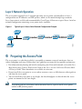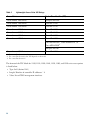
1
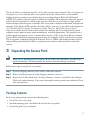
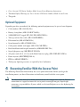
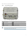
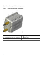
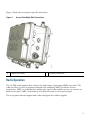
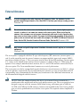
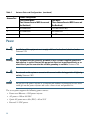
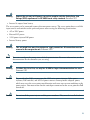
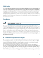
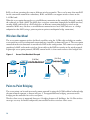
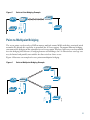
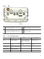
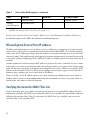
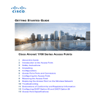
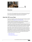
GETTING STARTED GUIDE
Cisco Aironet 1520 Series Outdoor Mesh Access Points
INCLUDING LICENSE AND WARRANTY
1
About this Guide
2
Introduction to the Access Point
3
Unpacking the Access Point
4
Becoming Familiar With the Access Point
5
Network Deployment Examples
6
Preparing the Access Point
7
Deploying the Access Point
8
In Case of Difficulty
9
Cisco 90-Day Limited Hardware Warranty Terms
1 About this Guide
This guide is designed to familiarize yourself with your Cisco Aironet 1520 Series Outdoor Mesh
Access Point and prepare it for use in your wireless network. Due to the complexity and number of
product options available, this guide does not provide detailed mounting and configuration
instructions. Those instructions can be found in the following documents:
• Cisco Mesh Networking Solution Deployment Guide
• Cisco Aironet 1520 Series Outdoor Mesh Access Point Hardware Installation Guide
• Cisco Aironet 1520 Series Access Point Power Injector Installation Instructions
Detailed configuration information can also be found in the Cisco wireless LAN controller
documentation for the controller and software release you are using. These and other documents are
available on Cisco.com. Follow these steps to access these documents:
Step 1
Browse to http://www.cisco.com.
Step 2
Click Support. A pop-up window appears.
Step 3
Click Wireless under View Information by Product Type. The Select Your Product or
Technology page appears.
Step 4
Enter Cisco Aironet 1520 Series in the Search for a Specific Product field and click Go. The
Cisco Aironet 1520 Series Introduction page appears.
Step 5
Choose the appropriate link for the documentation you want to view or download.
FCC Safety Compliance Statement
The FCC with its action in ET Docket 96-8 has adopted a safety standard for human exposure to radio
frequency (RF) electromagnetic energy emitted by FCC certified equipment. When used with approved
Cisco Aironet antennas, Cisco Aironet products meet the uncontrolled environmental limits found in
OET-65 and ANSI C95.1, 1991. Proper installation of this radio according to the instructions found
in this manual will result in user exposure that is substantially below the FCC recommended limits.
2
Declaration of Conformity with Regard to the EU Directive 1999/5/EC
(R&TTE Directive)
This declaration is only valid for configurations (combinations of software, firmware and hardware)
provided and/or supported by Cisco Systems. The use software or firmware not supported/provided
by Cisco Systems may result that the equipment is no longer compliant with the regulatory
requirements.
General Safety Guidelines
Warnings
Safety warnings appear throughout this guide in procedures that may harm you if performed
incorrectly. A warning symbol precedes each warning statement. The warnings below are general
warnings that are applicable to the entire guide. Specific warnings are included in the sections to which
they apply.
Translated versions of the safety warnings in this guide are provided in the Safety Warnings for
Cisco Aironet 1520 Series Outdoor Mesh Access Points document that accompanies this guide.
The translated warnings are also in Appendix A of the Cisco Aironet 1520 Series Outdoor Mesh
Access Point Hardware Installation Guide, which is available at cisco.com.
Warning
This warning symbol means danger. You are in a situation that could cause bodily injury.
Before you work on any equipment, be aware of the hazards involved with electrical
circuitry and be familiar with standard practices for preventing accidents. Use the
statement number provided at the end of each warning to locate its translation in the
translated safety warnings that accompanied this device.
Statement 1071
SAVE THESE INSTRUCTIONS
Warning
There is the danger of explosion if the battery is replaced incorrectly. Replace the battery
only with the same or equivalent type recommended by the manufacturer. Dispose of
used batteries according to the manufacturer’s instructions. Statement 1015
Warning
Do not operate the unit near unshielded blasting caps or in an explosive environment
unless the device has been modified to be especially qualified for such use.
Statement 364
3
Warning
This equipment must be externally grounded using a customer-supplied ground wire
before power is applied. Contact the appropriate electrical inspection authority or an
electrician if you are uncertain that suitable grounding is available.
Statement 366
Warning
Read the installation instructions before connecting the system to the power source.
Statement 1004
Warning
Only trained and qualified personnel should be allowed to install, replace, or service
this equipment. Statement 1030
Warning
Ultimate disposal of this product should be handled according to all national laws and
regulations. Statement 1040
2 Introduction to the Access Point
The Cisco Aironet 1520 Series Outdoor Mesh Access Point (hereafter called the access point) is a
modularized outdoor access point designed for service in mesh networks. The access point can be
configured for one or two radio operation. Its 802.11b/g radio is used primarily for local access and
its 802.11a radio is used to provide wireless backhaul in the mesh. The access point is LWAPP
compliant based on Cisco’s Internetwork Operating System (IOS).
With two radios installed, the access point provides client access on its 802.11b/g radio, point-to-point
bridging, point-to-multipoint bridging and mesh networking on its 802.11a radio. With one radio
installed, the access point provides client access and wireless backhaul over its 802.11b/g radio.
The 5-GHz radio incorporates an Unlicensed National Information Infrastructure (UNII) radio
transceiver that can operate in either the Upper ISM 5.8-GHz frequency band or the 4.9-GHz Public
Safety Band. The 5-GHz radio on the access point is used for backhaul operations to the controller.
Note
4
The 4.9-GHz Public Safety band requires a license and may be used only by qualified Public
Safety operators as defined in section 90.20 of the FCC rules.
The access point is a standalone unit that can be cable strand or tower mounted. The access point can
also operate as a relay node for other access points not directly connected to a wired network.
Intelligent wireless routing is provided by the patent-pending Adaptive Wireless Path Protocol
(AWPP). This enables each access point to identify its neighbors and intelligently choose the optimal
path to the wired network by calculating the cost of each path in terms of signal strength and the
number of hops required to get to a controller. The access point is configured, monitored, and operated
through a Cisco wireless LAN controller (hereafter called a controller) as described in the appropriate
Cisco Wireless LAN Controller Configuration Guide. The Cisco Mesh Networking Solution
Deployment Guide describes how to plan and initially configure the Cisco mesh network, which
supports wireless point-to-point, point-to-multipoint, and mesh deployments. The controllers use a
browser-based management system, a command-line interface (CLI), or the Cisco Wireless Control
System (WCS) network management system to manage the controller and the associated access points.
The access point is compliant with Wi-Fi Protected Access 2 (WPA2) and employs hardware-based
Advanced Encryption Standard (AES) encryption between wireless nodes to provide end-to-end
security.
3 Unpacking the Access Point
Note
When you are unpacking the access point, do not remove the foam blocks attached to the
antenna connectors. The foam protects the antenna connectors during installation.
Follow these steps to unpack the access point:
Step 1
Open the shipping container and carefully remove the contents.
Step 2
Return all packing materials to the shipping container and save it.
Step 3
Ensure that all items listed in the “Package Contents” section are included in the shipment.
Check each item for damage. If any item is damaged or missing, notify your authorized Cisco
sales representative.
Package Contents
Each access point package contains the following items:
• One 1520 series access point
• Installed mounting plate (attached to the back of the access point)
• Ground lug with screw and washer
5
• Cisco Aironet 1520 Series Outdoor Mesh Access Point Mounting Instructions
• Translated Safety Warnings for Cisco Aironet 1520 Series Outdoor Mesh Access Points
• This guide
Optional Equipment
Depending on what you ordered, the following optional equipment may be part of your shipment:
• Cable modem (AIR-1520-CM-D2=)
• Battery, 6 amp hour (AIR-1520-BATT-6AH=)
• 100BASE-BX10-U rugged SFP (GLC-FE-100BX-URGD=)
• Take-up reel for fiber cable (AIR-1520-FIB-REEL=)
• Pole mount kit (AIR-ACCMK1520=)
• Strand mount kit (AIR-ACCSMK1520=)
• Cable power module and supply (AIR-1520-CAB-PWR=)
• Band installation tool for pole mount kit (AIR-BAND-INS-TL=)
• Street light power tap (AIR-PWR-ST-LT-R3P=)
• AC power cord, 40 ft. (12.2 m) with North American plug (AIR-CORD-R3P-50NA=)
• Power injector (AIR-PWRINJ1500-2=)
• FIPS kit (AIRLAP-FIPSKIT=)
• Third-party lightning arrestors as required by local authorities
4 Becoming Familiar With the Access Point
The following illustrations show identify the access point connections. Before you begin the
installation process, use these illustrations to familiarize yourself with the access point.
Note
6
The illustrations show all available connections for the configuration ordered. Unused
connections are capped to ensure the access point’s watertight integrity. Liquid tight
connectors are provided for all ports, which can be installed prior to or after deploying the
access point.
Figure 1 shows the access point bottom connectors.
Figure 1
Access Point Bottom Connectors
1
AC power connector
5
Power-over-Ethernet (PoE) Out Ethernet connector
2
Reserved for future use
6
LEDs
3
Antenna port 6
7
Antenna port 4
4
Fiber optic connector
8
PoE-In Ethernet connector
Note
Antenna port 5 is not shown in this illustration. The port is reserved for future use and will
be located midway between antenna ports 4 and 6.
7
Figure 2 shows the access point left side and top connectors.
Figure 2
Access Point Left Side and Top Connectors
1
Fiber connector
4
Antenna port 2
2
Cable Power over Cable (PoC) connector
5
Antenna port 3
3
Antenna port 1
8
Figure 3 shows the access point right side connections.
Figure 3
1
Access Point Right Side Connections
Ground screw holes
2
DC power connector
Radio Operation
The 2.4-GHz radio supports three antennas for multi-input, single output (MISO) operation. The
radio uses three receivers to support maximum ratio combining (MRC) to enhance receiver
performance. MRC is a technique that combines the signals from multiple receivers in a manner to
optimize the signals. MRC can provide up to 3 dB of increased receive signal strength.
The access point does not support both radios configured for backhaul support.
9
External Antennas
Warning
In order to comply with radio frequency (RF) exposure limits, the antennas for this
product should be positioned no less than 6.56 ft (2 m) from your body or nearby persons.
Statement 339
Warning
Do not locate the antenna near overhead power lines or other electric light or power
circuits, or where it can come into contact with such circuits. When installing the
antenna, take extreme care not to come into contact with such circuits, because they
may cause serious injury or death. For proper installation and grounding of the antenna,
please refer to national and local codes (for example, U.S.:NFPA 70, National Electrical
Code, Article 810, Canada: Canadian Electrical Code, Section 54). Statement 1052
Warning
Only trained and qualified personnel should be allowed to install, replace, or service this
equipment.
Statement 1030
The access point is equipped with three N-type radio frequency (RF) connectors (antenna ports 1, 2,
and 3) on the top of the unit for external antennas to support multiple input single output (MISO)
operation as shown in Figure 1. The access point also has three N-type RF connectors (antenna ports
4, 5, and 6) on the bottom of the unit for external antennas as shown in Figure 2. When using the
optional Cisco compact omnidirectional antennas, the 2.4- and 5-GHz antennas connect directly to
the access point. The Cisco omnidirectional antennas use vertical polarization.
The access point can also be equipped with specific third-party external antennas (see Table 1), subject
to local regulatory requirements. If you install third-party antennas, be sure to install them with all
waterproofing steps recommended by the third-party manufacturer. For additional information, see
the documentation shipped with the antenna.
Note
10
The FCC limits the amount of power this device can transmit. Power transmitted is a
combination of the amplification of the signal and the antenna gain. The access point has been
designed to operate with the antennas listed below having a maximum gain of 8 dBi for
2.5-GHz and 17 dBi for 5-GHz antennas. Antennas not included in this list or having a higher
gain are strictly prohibited for use with the access point. The required antenna impedance is
50 ohms.
Note
To reduce potential radio interference to other users, the antenna type and its gain should be
chosen so that the equivalent subtropical radiated power (EIRP) is not more than required for
successful communication.
Table 1 lists the supported external 2.4- and 5-GHz antennas.
Table 1
External 2.4- and 5-GHz Antennas
Part Number
Model
Gain (dBi)
AIR-ANT2450V-N
2.4-GHz compact omnidirectional
AIR-ANT2480V-N
2.4-GHz omnidirectional
AIR-ANT5180V-N
5-GHz compact
AIR-ANT5114P-N
AIR-ANT5117S-N
5-GHz sector
4.9- to 5-GHz
5.5
8.0
omnidirectional2
4.9-GHz compact omnidirectional
AIR-ANT58G10SSA-N
1
8.0
3
7.0
9.5
patch2
14.0
4.9- to 5-GHz 90-degree sector
2
17.0
1. The compact omnidirectional antennas mount directly on the access point.
2. The compact omnidirectional antennas mount directly on the access point.
3. Use of the 4.9-GHz band requires a license and may be used only by qualified Public Safety operators as defined in
section 90.20 of the FCC rules.
Antenna Configurations
Two antenna configurations are available, based on how the access point is mounted. The cable strand
mounting configuration uses three antennas and the tower mount configuration uses four antennas.
Table 2 identifies the antenna ports used and explains the configurations.
Table 2
Antenna Ports and Configurations
Antenna Port
Product Configuration
Cable Strand Mount
(Two Antenna Receive MRC Access and
One Backhaul)
Pole Mount
(Three Antenna Receive MRC Access and
One Backhaul)
1
2.4-GHz receive only
5-GHz receive and transmit
2
5-GHz transmit and receive
No connection
3
2.4-GHz transmit and receive
2.4-GHz receive only
11
Table 2
Antenna Ports and Configurations (continued)
Antenna Port
Product Configuration
Cable Strand Mount
(Two Antenna Receive MRC Access and
One Backhaul)
Pole Mount
(Three Antenna Receive MRC Access and
One Backhaul)
4
No connection
2.4-GHz receive only
5
No connection
No connection
6
No connection
2.4-GHz transmit and receive
Power
Warning
Installation of the equipment must comply with local and national electrical codes.
Statement 1074
Warning
This equipment must be externally grounded using a customer-supplied ground wire
before power is applied. Contact the appropriate electrical inspection authority or an
electrician if you are uncertain that suitable grounding is available. Statement 366
Warning
Do not work on the system or connect or disconnect cables during periods of lightning
activity. Statement 1001
Caution
Do not place the power injector in an unprotected outdoor environment because water
could get into the power injector and cause a short circuit and possible fire.
The access point supports the following power sources:
• Power-over-Ethernet—1520 power injector
• AC power—100 to 480 VAC
• Quazi-AC power-over-cable (POC)—40 to 90 V
• External 12 VDC power
12
Warning
Connect the unit only to DC power source that complies with the Safety Extra-Low
Voltage (SELV) requirements in IEC 60950 based safety standards Statement 1033
• Internal 6 ampere-hour battery
The access point can be connected to more than one power source. The access point detects available
input sources and switches to the preferred power source using the following prioritization:
• AC or POC power
• External DC power
• 1520 power injector PoE power
• Internal battery power
Warning
Note
This unit might have more than one power supply connection. All connections must be
removed to de-energize the unit. Statement 1028
You can reconfigure the power source default prioritization. For more information, see the
documentation for the controller you are using.
Warning
To reduce the risk of fire, use only No. 26 AWG or larger telecommunication line cord.
Statement 1023
Caution
To provide inline PoE, you must use the 1520 series power injector. Other power
injectors, PoE switches, and 802.3af power sources cannot provide adequate power,
which may cause the access point to malfunction and cause over-current conditions at the
power source. You must ensure that the switch port connected to the access point has PoE
turned off.
Caution
Do not install the power injector and the power outdoors. They must be installed indoors.
13
Caution
When the access point is installed outdoors or in a wet or damp location, the AC branch
circuit that is powering the access point should be provided with ground fault protection
(GFCI), as required by Article 210 of the National Electrical Code (NEC).
Three AC power cord options are available:
• 40-ft (12.2-m) power cord for light pole installations in the US and Canada. One end of the power
cord is terminated with an access point AC power connector and the other end is terminated
with an AC plug (AIR-CORD-R3P-50NA=).
• 40-ft (12.2-m) power cord for use outside the US and Canada. One end of the power cord is
terminated with an access point AC power connector and the other end is unterminated.
(AIR-CORD-R3P-50UE=).
• 4-ft (1.2-m) streetlight power tap adapter for light pole installations in the US and Canada
(AIR-PWR-ST-LT-R3P=).
Ethernet (PoE) Ports
The access point supports an Ethernet uplink port (POE-In) and a downlink port (POE-Out). The
access point’s Ethernet uplink port uses an RJ-45 connector (with weatherproofing) to link the access
point to the 10BASE-T, 100BASE-T, or 1000BASE-T network. The Ethernet cable is used to send and
receive Ethernet data and to optionally supply inline 56-VDC power from the power injector. The
minimum length of this cable must be not less than 10 feet (3 meters).
The access point’s downlink Ethernet port uses an RJ-45 connector (with weatherproofing) to provide
LAN connectivity and IEEE 802.3af power to a peripheral customer device, such as a camera or sensor
gateway. The BVI MAC addresses are printed on the label on the side of the access point
Tip
Caution
14
The access point senses the Ethernet and power signals and automatically switches internal
circuitry to match the cable connections.
To provide inline PoE, you must use the 1520 series power injector. Other power
injectors, PoE switches, and 802.3af power sources can not provide adequate power,
which may cause the access point to malfunction and cause possible over-current
conditions at the power source.
Cable Option
The factory-orderable cable option provides a cable modem and Power-over-Cable capabilities for the
access point for high-speed data transfer and Internet access. When the cable option is installed, the
access point uses its F-type cable connection to receive both data and power. Data is passed between
wireless clients on the mesh network to the cable company’s network via the access point’s internal
cable modem. In this configuration, the access point receives operating power from the cable. For
detailed installation information, see the Cisco Aironet 1520 Series Outdoor Access Point Hardware
Installation Guide. Configuration information can be found in the controller configuration guide of
the controller you are using.
Fiber Option
Warning
Class 1 laser product. Statement 1008
The factory-orderable fiber option provides a fiber input and output capability. Fiber is data is
transmitted and received over a single-strand fiber cable which is connected to the access point using
a rugged 100BASE-BX10-U fiber small factor pluggable (SFP) module. For convenience, two fiber
connections are available on the access point. One connection is on the bottom of the unit (shown on
Figure 1) and the other on the left side (shown on Figure 2). Client data is passed to the network
controller through the fiber connection via a fiber capable switch. For detailed installation information
about the fiber option, see the Cisco Aironet 1520 Series Outdoor Mesh Access Point Hardware
Installation Guide. Configuration information can be found in the controller configuration guide of
the controller you are using.
5 Network Deployment Examples
The access point is a wireless device designed for wireless client access and point-to-point bridging,
point-to-multipoint bridging, and point-to-multipoint mesh wireless connectivity. The access point
provides 5-GHz backhaul capability to link with another access point to reach a wired network
connection or to provide repeater operations for other access points.
The access point plays two primary radio roles: a root access point (hereafter called a RAP) or a
non-root access point (hereafter called a MAP), which is the default role of all access points. When the
access point has a wired Ethernet or cable connector connection to the controller (through a switch),
the radio role is called a RAP. In order to be considered a RAP, the access point must be configured as
a RAP. A RAP is a parent node to any bridging or mesh network. A controller can support one or more
15
RAPs, each one parenting the same or different wireless networks. There can be more than one RAP
for the same mesh network for redundancy. RAPs and MAPs can support wireless clients on the
2.4-GHz band.
When the access point does not have a wired Ethernet connection to the controller (through a switch),
the radio role is called a MAP. The MAPs have a wireless connection (through the backhaul interface)
to other MAPs and finally to a RAP which has an Ethernet connection through a switch to the
controller. MAPs may also have a wired Ethernet connection to a local LAN and serve as a bridge
endpoint for that LAN (using a point-to-point or point-to-multipoint bridge connection).
Wireless Backhaul
The access point supports wireless backhaul capability using the 5-GHz radio to bridge to another
access point to reach a wired network connection to a controller as shown in Figure 4. The access point
connected to the wired network is considered a RAP in this configuration. The remote access point is
considered a MAP and transfers wireless client traffic to the RAP for transfer to the wired network.
Lightweight access point protocol (LWAPP) control traffic is also transferred over this bridged link.
Figure 4
Access Point Backhaul Example
(2.4 Ghz)
148438
(5.8 Ghz)
Point-to-Point Bridging
The access points can be used to extend a remote network by using the 5-GHz backhaul radio to bridge
the two network segments as shown in Figure 5. To support Ethernet bridging, you must enable
bridging on the controller for each access point.
Wireless client access is supported; however, if bridging between tall buildings, the 2.4-Ghz wireless
coverage area may be limited and possibly not suitable for direct wireless client access.
16
Point-to-Point Bridging Example
148440
Figure 5
Point-to-Multipoint Bridging
The access points can be used as a RAP to connect multiple remote MAPs with their associated wired
networks. By default this capability is turned-off for all access points. To support Ethernet bridging,
you must enable bridging on the controller for each access point. Wireless client access can be provided
over the bridging link; however, if bridging between tall buildings, the 2.4-Ghz wireless coverage area
may be limited and possibly not suitable for direct wireless client access.
Figure 6 illustrates an example of access point-to-multipoint bridging.
Point-to-Multipoint Bridging Example
148439
Figure 6
17
Mesh Network
The access point is typically deployed in a mesh network configuration. In a typical mesh deployment,
one or more RAPs have a wired network connection through a switch to a controller. Other remote
MAPs without wired network connections use the backhaul feature to optimally link to a RAP that is
connected to the wired network. In the mesh network, the links between the access points are referred
to as the backhaul links.
Intelligent wireless routing is provided by the patent-pending Adaptive Wireless Path protocol
(AWPP). This enables each MAP to identify its neighbors and intelligently choose the optimal path to
the RAP with the wired network connection by calculating the cost of each path in terms of signal
strength and the number of hops required to get to a controller with signal strength given priority since
signal strength determines the bandwidth available for backhaul.
Figure 7 illustrates a typical mesh configuration using MAPs and RAPs.
Figure 7
Typical Mesh Configuration Using MAPs and RAPs
RAP
Network
WCS
MAP 4
MAP 7
18
MAP 2
MAP 3
MAP 6
MAP 5
MAP 8
MAP 9
148441
MAP 1
Layer 3 Network Operation
The access points support Layer 3 network operation. Access points and controllers in Layer 3
configurations use IP addresses and UDP packets, which can be routed through large networks.
Layer 3 operation is scalable and recommended by Cisco. Figure 8 illustrates a typical Layer-3 wireless
network configuration containing access points and a controller.
Typical Layer 3 Access Point Network Configuration Example
148458
Figure 8
6 Preparing the Access Point
The access point is a radio device which is susceptible to common causes of interference that can
reduce throughput and range. Follow these basic guidelines to ensure the best possible performance:
• For information on planning and initially configuring your Cisco mesh network, refer to the Cisco
Mesh Networking Solution Deployment Guide or the Cisco Aironet 1500 Series Wireless Mesh
AP Design Guide. These documents are available on cisco.com.
• Do not install the access point in an area where structures, trees, or hills obstruct radio signals to
and from the access point.
• You can install the access point at any height, but best throughput is achieved when the access
points are mounted at the same height.
Note
To perform path loss calculation and to determine how far apart to install access points,
consult an RF planning expert.
19
Site Surveys
Cisco recommends that you perform a site survey before installing the equipment. A site survey reveals
problems that can be resolved before the network is operational. Because 802.11a is unlicensed, there
may be sources of interference from other 802.11a wireless devices (especially in multi-tenant
buildings) that could degrade your 802.11 signals. A site survey can determine if such interference
exists.
A proper site survey involves temporarily setting up mesh links and taking measurements to determine
whether your antenna calculations are accurate. Determine the correct locations and antenna types
before you drill holes and route cables and mounting equipment.
Tip
When power is not readily available during a site survey, use an unrestricted power supply
(UPS) to temporarily power the mesh link.
Consider the following operating and environmental conditions when performing a site survey:
• How far is your wireless link?
• Has a previous site survey been conducted?
• Do you have a clear Fresnel zone between the access points or radio line of sight?
• What is the minimum acceptable data rate within the link?
• Do you have the correct antenna?
• Do you have access to both of the mesh site locations?
• Do you have the proper permits, if required?
• Do you have a partner? Never attempt to survey or work alone on a roof or tower.
• Have you configured the access points before you go onsite? It is always easier to resolve
configurations or device problems first.
• Do you have the proper tools and equipment to complete your survey?
Avoiding Damage to Radios in a Testing Environment
The radios on outdoor units (bridges) have higher transmit power levels than radios on indoor units
(access points). When you test high power radios in a link, you must avoid exceeding the receiver’s
maximum receive input level. At levels higher than the normal the receiver’s operating range, packet
error rate (PER) performance is degraded. At even higher levels, the receiver can be permanently
damaged.
20
To avoid receiver damage and PER degradation, you can use one of the following techniques:
• Separate the omnidirectional antennas by at least 2 ft (0.6 m) to avoid receiver damage or by at
least 25 ft (7.6 m) to avoid PER degradation.
Note
These distances assume free space path loss and are conservative estimates. Required
separation distances for damage and performance degradation levels in actual
deployments will be less due to non line-of-sight propagation conditions.
• Reduce the configured transmit power to the minimum level.
• Use directional antennas and keep them pointed away from each other.
• Cable the radios together using a combination of attenuators, combiners, or splitters to achieve a
total attenuation of at least 60 dB.
For a radiated test bed, the following equation describes the relationships among transmit power,
antenna gain, attenuation, and receiver sensitivity:
txpwr + tx gain + rx gain - [attenuation due to antenna spacing] < max rx input level
Where:
txpwr = Radio transmit power level
tx gain = transmitter antenna gain
rx gain = receiver antenna gain
For a conducted test bed, the following equation describes the relationships among transmit power,
antenna gain, and receiver sensitivity:
txpwr - [attenuation due to coaxial components] < max rx input level
Caution
Under no circumstances should you connect the antenna port from one access point to the
antenna port of another access point without using an RF attenuator. If you connect
antenna ports you must not exceed the maximum survivable receive level of 0 dBm. Never
exceed 0 dBm or damage to the access point can occur. Using attenuators, combiners, and
splitters having a total of at least 60 dB of attenuation ensures that the receiver is not
damaged and PER performance is not degraded.
21
Before You Begin
Warning
Read the installation instructions before connecting the system to the power source.
Statement 1004
Before you begin the installation process:
• Become familiar with the procedures for mounting the access point.
• Become familiar with the access point connections (Figure 1 on page 7, Figure 2 on page 8, and
Figure 3 on page 9).
• Verify that the switch you are using to connect the controller is configured properly.
Note
For additional installation, mounting and safety information for the outdoor mesh access
point, see the Cisco Aironet 1520 Series Outdoor Mesh Access Point Hardware Installation
Guide, which is available on Cisco.com, and Safety Warnings for Cisco Aironet 1520 Series
Outdoor Mesh Access Points , which accompanies this guide.
7 Deploying the Access Point
Warning
Do not operate the unit near unshielded blasting caps or in an explosive environment
unless the device has been modified to be especially qualified for such use. Statement 364
The access point is deployed on Layer 3 networks. Layer 3is the default mode for a newly configured
wireless LAN controller. This guide assumes that you will be deploying your access point on a Layer
3 network and a DHCP server is available.
Before deploying the access point, make sure the controller to which the access point will associate is
properly configured by performing the following operations:
• Make sure that the wireless LAN controller is set to Layer 3 mode
• Verify the wireless LAN controller software version
• Record the access point BVI MAC address
• Enter the access point BVI MAC address to the wireless LAN controller filter list
22
Verifying the Wireless LAN Controller Mode
Follow these steps to verify that the wireless LAN controller mode is set to Layer 3:
Step 1
Open your web-browser and enter the IP address of your wireless LAN controller. Be sure to
precede the IP address with https://. A login screen appears.
Step 2
Enter your username and password. The default case-sensitive username and password are
admin and admin. The Summary page appears.
Step 3
From the top menu bar, click CONTROLLER. The Controller General page appears.
Step 4
Verify that the LWAPP Transport Mode is set to Layer 3. If it is not, change it to Layer 3 and
click Apply.
Step 5
Save any changes you made.
Step 6
From the menu bar, click MONITOR to return to the Monitor Summary page.
Verifying the Wireless LAN Controller Software Version
On the Summary page, you can verify the software version that the wireless LAN controller is running.
If a version update is necessary, refer to the appropriate controller configuration documentation.
Recording the Access Point MAC Address
Use a text file to record the MAC address of all the access points you intend to deploy in your network.
Having a file of access point MAC addresses will be of considerable value for future testing. While you
are compiling the list, you might want to change the name of the access point to something you can
easily remember. The name can contain up to 32 characters. The following example, fisher_street:ea:co
contains the last four HEX characters of the access point MAC address.
Adding the Access Point MAC Address to the Wireless LAN Controller
Filter List
The wireless LAN controller maintains an access point authorization MAC address list and responds
to discovery requests from access points on that list. Follow these steps to add the access point MAC
address (or MAC addresses) to the Wireless LAN controller filter list:
Step 1
If you are not logged onto the wireless LAN controller, log on now. The Summary page
appears.
Step 2
On the menu bar, click SECURITY. The Security RADIUS Authentication Server page
appears.
23
Step 3
Under AAA in the left frame, click MAC Filtering. The Security MAC Filtering page appears.
Step 4
Click New. The MAC Filters New page appears.
Step 5
Enter the MAC address of the access point in the MAC Address field. You can also use the
config macfilter add command to add a MAC filter entry to the controller.
Step 6
Select a WLAN ID or Any WLAN from the WLAN ID pop-up menu.
Step 7
Enter a description (32 characters maximum) of the access point in the Description field.
Step 8
Choose an interface from the Interface Name pop-up menu.
Step 9
Click Apply.
Step 10 Repeat this process to add other access points to the list.
Note
You can also use the controller CLI command config macfilter add to add a MAC
filter entry on the controller.
Step 11 On the menu bar, click Monitor to return to the Monitor Summary page.
Verifying Controller Association
To verify that your access point is associated to the wireless LAN controller, perform these steps:
Step 1
Log into your controller web interface (https) using a web browser.
Step 2
Click Wireless and verify that your access point MAC address is listed under Ethernet MAC.
Step 3
Log out of the controller and close your web browser.
24
Deployment Notes
Using a DHCP Server in a Layer 3 Mesh Network
To use a DHCP server in a Layer 3 mesh network, make sure the wireless LAN controller is in Layer
3 mode. You must also configure DHCP option 43 on the DHCP server. After the controller is
restarted, the access point receives IP addresses from the DHCP server.
Configuring DHCP Option 43
You can use DHCP Option 43 to provide a list of controller IP addresses to the access points, enabling
each access point to find and join a controller. This section contains a DHCP Option 43 configuration
example on a Microsoft Windows 2003 Enterprise DHCP server for use with Cisco Aironet
lightweight access points.
Additional information about Microsoft DHCP Option 43 is available at cisco.com at the following
URL:
http://www.cisco.com/en/US/products/hw/wireless/ps430/prod_technical_reference09186a00804fc3d
c.html#wp125304
DHCP Option 43 server implementation information for Cisco IOS is available at cisco.com at the
following URL:
http://www.cisco.com/en/US/docs/wireless/technology/controller/deployment/guide/dep.html#wp106
8287
Note
In DHCP Option 43, you should use the IP address of the controller management interface.
Note
DHCP Option 43 is limited to one access point type per DHCP pool. You must configure a
separate DHCP pool for each access point type.
Cisco Aironet 1000 and 1500 (1505 and 1510) series access points use a comma-separated string
format for DHCP Option 43. Other Cisco Aironet access points use the type-length-value (TLV)
format for DHCP Option 43. DHCP servers must be programmed to return the option based on the
access point’s DHCP Vendor Class Identifier (VCI) string (DHCP Option 60). The VCI strings for
Cisco access points capable of operating in lightweight mode are listed in Table 3:
25
Table 3
Lightweight Access Point VCI Strings
Access Point
Vendor Class Identifier (VCI)
Cisco Aironet 1000 Series
Airespace.AP1200
Cisco Aironet 1100 Series
Cisco AP c1100
Cisco Aironet 1130 Series
Cisco AP c1130
Cisco Aironet 1200 Series
Cisco AP c1200
Cisco Aironet 1240 Series
Cisco AP c1240
Cisco Aironet 1300 Series
Cisco AP c1300
Cisco Aironet 1500 Series
Cisco AP c1500 1
Cisco AP.OAP15002, Cisco AP.LAP15102, or
Cisco AP.LAP15052
Airespace.AP12003
Cisco Aironet 1520 Series
Cisco AP c1520
1. For controller release 4.1 or later.
2. For controller release 4.0, the VCI depends on the model.
3. For controller release 3.2.
The format of the TLV block for 1100, 1130, 1200, 1240, 1250, 1300, and 1520 series access points
is listed below:
• Type: 0xf1 (decimal 241)
• Length: Number of controller IP addresses * 4
• Value: List of WLC management interfaces
26
To configure DHCP Option 43 for Cisco 1000 and 1500 (1505 and 1510) series lightweight access
points in the embedded Cisco IOS DHCP server, follow these steps:
Step 1
Enter configuration mode at the Cisco IOS command line interface.
Step 2
Create the DHCP pool, including the necessary parameters such as default router and name
server as shown in the following example:
ip dhcp pool pool name
network IP Network Netmask
default-router Default router
dns-server DNS Server
Where:
pool name is the name of the DHCP pool, such as AP1000.
IP Network is the network IP address where the controller resides, such as
10.0.15.1
Netmask is the subnet mask, such as 255.255.255.0
Default router is the IP address of the default router, such as 10.0.0.1
DNS Server is the IP address of the DNS server, such as 10.0.10.2
Step 3
Add the Option 60 line using the following syntax:
option 60 ascii “VCI string”
For the VCI string, use the value from Table 3. The quotation marks must be included.
Step 4
Add the Option 43 line using the following syntax:
option 43 ascii “Comma Separated IP Address List”
For example, if you are configuring Option 43 for Cisco 1000 or 1500 series access points
using the controller IP addresses 10.126.126.2 and 10.127.127.2, add the following line to
the DHCP pool in the Cisco IOS CLI. Be sure to include the quotation marks:
option 43 ascii “10.126.126.2,10.127.127.2”
The quotation marks must be included.
27
To configure DHCP Option 43 for Cisco Aironet 1100, 1130, 1200, 1240, 1250, 1300, and 1520 series
lightweight access points in the embedded Cisco IOS DHCP server, follow these steps:
Step 1
Enter configuration mode at the Cisco IOS CLI.
Step 2
Create the DHCP pool, including the necessary parameters such as default router and name server.
The commands used to create a DHCP pool are as follows:
ip dhcp pool pool name
network IP Network Netmask
default-router Default router
dns-server DNS Server
Where:
pool name is the name of the DHCP pool, such as AP1520.
IP Network is the network IP address where the controller resides, such as
10.0.15.1
Netmask is the subnet mask, such as 255.255.255.0
Default router is the IP address of the default router, such as 10.0.0.1
DNS Server is the IP address of the DNS server, such as 10.0.10.2
Step 3
Add the Option 60 line using the following syntax:
option 60 ascii “VCI string”
For the VCI string, use the value from Table 3. The quotation marks must be included.
Step 4
Add the option 43 line using the following syntax:
option 43 hex hex string
The hex string is assembled by concatenating the TLV values shown below:
Type + Length + Value
Type is always f1(hex). Length is the number of controller management IP addresses times 4
in hex. Value is the IP address of the controller listed sequentially in hex.
For example, suppose that there are two controllers with management interface IP addresses,
10.126.126.2 and 10.127.127.2. The type is f1(hex). The length is 2 * 4 = 8 = 08 (hex). The
IP addresses translate to 0a7e7e02 and 0a7f7f02. Assembling the string then yields
f1080a7e7e020a7f7f02. The resulting Cisco IOS command added to the DHCP scope is listed
below:
option 43 hex f1080a7e7e020a7f7f02
28
8 In Case of Difficulty
Help is available from Cisco should you experience difficulties; however, before contacting Cisco, look
for a solution to your problem in the following places:
• The Troubleshooting section of this guide
• The troubleshooting section of the Cisco Aironet 1520 Series Outdoor Mesh Access Point
Hardware Installation Guide
• The Troubleshooting a Mesh Network troubleshooting guide found on cisco.com at
http://www.cisco.com/en/US/products/ps8368/prod_troubleshooting_guides_list.html
• The Tools and Resources section on the Technical Support and Documentation page at cisco.com
Follow these steps to contact the Technical Assistance Center on cisco.com:
Step 1
Open your browser and go to http://www.cisco.com/.
Step 2
Click Support. The Support page appears.
Step 3
Choose the link that best serves your support requirements.
Note
Step 4
Click My Tech Support if you are a registered user.
Follow the instructions on the page.
Troubleshooting
Caution
No serviceable parts inside. Do not open.
This section provides troubleshooting procedures for basic problems with the access point. For the
most up-to-date, detailed troubleshooting information, refer to the Cisco Support website at
cisco.com.
29
Guidelines for Using the Access Point
You should keep these guidelines in mind when you use the access point:
• The access points can only communicate with controllers and cannot operate independently.
• The access point communicates only with controllers and does not support Wireless Domain
Services (WDS). The access points cannot communicate with WDS devices. However, the
controller provides functionality equivalent to WDS when an access point associates to it.
• The access point supports Layer 3 LWAPP communications with the controllers. In Layer 3
operation, the access point and the controller can be on the same or different subnets. The access
point communicates with the controller using standard IP packets. Layer 3 operation is scalable
and is recommended by Cisco. Unless it has a static IP address, a Layer 3 access point on a different
subnet than the controller requires a DHCP server on the access point subnet and a route to the
controller. The route to the controller must have destination UDP ports 12222 and 12223 open
for LWAPP communications. The routes to the primary, secondary, and tertiary controllers must
allow IP packet fragments.
• Before deploying your mesh access points ensure that the following has been done:
– Your controllers are connected to switch ports that are configured as trunk ports.
– Your mesh access points are connected to switch ports that are configured as untagged access
ports.
– A DHCP server is reachable by your mesh access points and has been configured with Option
43. Option 43 is used to provide the IP addresses of the Management Interfaces of your
controllers. Typically, a DHCP server can be configured on a Cisco Layer 3 switch or router.
– Optionally a DNS server can be configured to enable a local domain Cisco LWAPP controller
(CISCO-LWAPP-CONTROLLER.<local domain>) to resolve to the IP address of the
Management Interface of your controller.
– Your controllers are configured and reachable by the mesh access points.
– Your controllers are configured with the MAC addresses of the mesh access points.
Checking the LEDs
Four LEDs, located between the PoE-In and PoE-Out connectors, monitor the status of the access
point’s power, uplinks, and radios. Figure 9 identifies and describes the LED functions. Table 4
provides additional LED information.
30
Figure 9
LEDs
1
Status LED— Displays the current status of
the access point and power.
3
Radio 1 Status LED—Displays the status of
the 802.11b/g radio.
2
Uplink Status LED—Displays the status of all 4
uplink connections (Ethernet, fiber, and
cable).
Radio 2 Status LED—Displays the status of
the 802.11a radio.
Table 4
Access Point LED Descriptions
Color1
Status LED
Uplink LED
RF-1 and RF-2 LEDs
Dark
No power applied
No physical connector
present or uplink port is
down.
Radio turned off
Green
Access point operating
normally
Uplink ports operating
normally
Radios operating
normally
Blinking green
Loading or upgrading IOS –
image
–
Blinking amber
Authentication mode
–
–
Amber
Neighbor discovery
–
–
31
Table 4
Access Point LED Descriptions (continued)
Color1
Status LED
Uplink LED
RF-1 and RF-2 LEDs
Red
Firmware failure
–
Firmware failure
Cycling
red/amber/green
LWAPP discovery
–
–
1. All LEDs dark indicates no power is applied.
All LEDs amber indicates the access point power supply is on.
See the Cisco Aironet 1520 Series Outdoor Mesh Access Point Hardware Installation Guide for a
detailed description of the LEDs and additional troubleshooting tips.
Misconfigured Access Point IP address
IP address misconfiguration can occur when you are re-addressing a segment of your mesh network
and you start at the mesh access point connected to the wired network (RAP). To avoid this problem,
always start the IP addressing changes from the farthest access point and work your way back to the
root access point. This problem might also happen if you move equipment such as uninstalling an mesh
access point and then redeploying with a different IP subnet in another physical location on the mesh
network.
Another option to fix this misconfigured IP address is to physically take a controller in Layer 3 mode
with a root access point to the location of the misconfigured mesh access point. Set the bridge group
name for the root access point to match the misconfigured access point. Add the access point’s MAC
address to the controller’s filter list. When the misconfigured access point appears in the controller’s
Summary page, configure the access point with an IP address.
If you are using a static IP address on the access point and plan on redeploying the access point on
another subnet, perform a clear config command from the controller for that access point while it is
joined before you remove it from the network.
Verifying the Controller MAC Filter List
Prior to activating your access point, you must ensure that the access point MAC address has been
added to the controller MAC Filter list and that Mac Filter List is enabled. To view the MAC addresses
added to the controller MAC filter list and ensure the MAC filter list is enabled, you can use the
controller CLI or the controller GUI.
32
Controller CLI
Use the show macfilter summary controller CLI command to view the MAC addresses added to the
controller filter list.
Controller GUI
Log into your controller web interface (HTTPS) using a web browser and click SECURITY > AAA >
MAC Filtering to view the MAC addresses added to the controller filter list. Then click Wireless >
Mesh to ensure the MAC filter list is enabled.
9 Cisco 90-Day Limited Hardware Warranty Terms
There are special terms applicable to your hardware warranty and various services that you can use
during the warranty period. Your formal Warranty Statement, including the warranties and license
agreements applicable to Cisco software, is available on Cisco.com. Follow these steps to access and
download the Cisco Information Packet and your warranty and license agreements from Cisco.com.
1. Launch your browser, and go to this URL:
http://www.cisco.com/univercd/cc/td/doc/es_inpck/cetrans.htm
The Warranties and License Agreements page appears.
2. To read the Cisco Information Packet, follow these steps:
a. Click the Information Packet Number field, and make sure that the part number
78-5235-03D0 is highlighted.
b. Select the language in which you would like to read the document.
c. Click Go.
The Cisco Limited Warranty and Software License page from the Information Packet appears.
d. Read the document online, or click the PDF icon to download and print the document in
Adobe Portable Document Format (PDF).
Note
You must have Adobe Acrobat Reader to view and print PDF files. You can download
the reader from Adobe’s website: http://www.adobe.com
3. To read translated and localized warranty information about your product, follow these steps:
a. Enter this part number in the Warranty Document Number field:
78-5236-01C0
b. Select the language in which you would like to view the document.
33
c. Click Go.
The Cisco warranty page appears.
d. Read the document online, or click the PDF icon to download and print the document in
Adobe Portable Document Format (PDF).
You can also contact the Cisco service and support website for assistance:
http://www.cisco.com/en/US/support/
The following are special terms applicable to your hardware warranty.
Duration of Hardware Warranty
Ninety (90) Days
Replacement, Repair, or Refund Policy for Hardware
Cisco or its service center will use commercially reasonable efforts to ship a replacement part within
ten (10) working days after receipt of a Return Materials Authorization (RMA) request. Actual
delivery times can vary, depending on the customer location.
Cisco reserves the right to refund the purchase price as its exclusive warranty remedy.
To Receive a Return Materials Authorization (RMA) Number
Contact the company from whom you purchased the product. If you purchased the product directly
from Cisco, contact your Cisco Sales and Service Representative.
Complete the information below, and keep it for your reference.
Company product purchased from
Company telephone number
Product model number
Product serial number
Maintenance contract number
34
35
Americas Headquarters
Cisco Systems, Inc.
170 West Tasman Drive
San Jose, CA 95134-1706
USA
www.cisco.com
Tel: 408 526-4000
800 553-NETS (6387)
Fax: 408 527-0883
Asia Pacific Headquarters
Cisco Systems, Inc.
168 Robinson Road
#28-01 Capital Tower
Singapore 068912
www.cisco.com
Tel: +65 6317 7777
Fax: +65 6317 7799
Europe Headquarters
Cisco Systems International BV
Haarlerbergpark
Haarlerbergweg 13-19
1101 CH Amsterdam
The Netherlands
www-europe.cisco.com
Tel: 31 0 800 020 0791
Fax: 31 0 20 357 1100
Cisco has more than 200 offices worldwide. Addresses, phone numbers, and fax numbers are listed on the
Cisco Website at www.cisco.com/go/offices.
CCVP, the Cisco logo, and the Cisco Square Bridge logo are trademarks of Cisco Systems, Inc.; Changing the Way We Work, Live, Play, and Learn
is a service mark of Cisco Systems, Inc.; and Access Registrar, Aironet, BPX, Catalyst, CCDA, CCDP, CCIE, CCIP, CCNA, CCNP, CCSP, Cisco,
the Cisco Certified Internetwork Expert logo, Cisco IOS, Cisco Press, Cisco Systems, Cisco Systems Capital, the Cisco Systems logo, Cisco Unity,
Enterprise/Solver, EtherChannel, EtherFast, EtherSwitch, Fast Step, Follow Me Browsing, FormShare, GigaDrive, HomeLink, Internet Quotient,
IOS, iPhone, IP/TV, iQ Expertise, the iQ logo, iQ Net Readiness Scorecard, iQuick Study, LightStream, Linksys, MeetingPlace, MGX, Networking
Academy, Network Registrar, Packet, PIX, ProConnect, ScriptShare, SMARTnet, StackWise, The Fastest Way to Increase Your Internet Quotient,
and TransPath are registered trademarks of Cisco Systems, Inc. and/or its affiliates in the United States and certain other countries.
© 2007 Cisco Systems, Inc. All rights reserved.
Printed in the USA on recycled paper containing 10% postconsumer waste.
78-18179-03
DOC-78-18179=