1
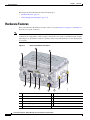
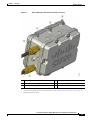
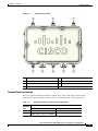
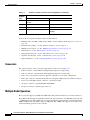
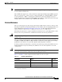
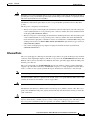
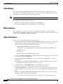
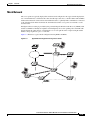
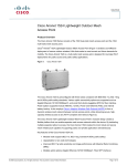
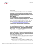
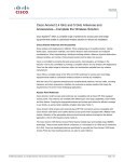
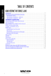
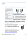
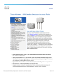
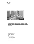
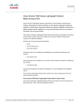
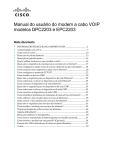
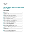
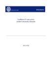
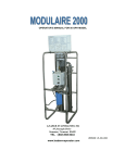
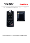
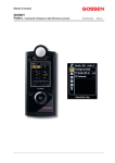
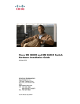
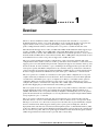
CH A P T E R
1
Overview
The Cisco Aironet 1520 Series Outdoor Mesh Access Point (hereafter called the access point) is a
modularized wireless outdoor access point designed for use in a mesh network. The access point also
supports wireless client access, point-to-point bridging, point-to-multipoint bridging, and
point-to-multipoint mesh wireless connectivity. The access point is a standalone unit that can be
The LAP1522 model supports two radios (2.4-GHz and 5-GHz) and the LAP1524 model supports up to
4 radios (2.4-GHz, 5.8-GHz, and 4.9-GHz public safety band). Both models provide client access
without the need for a license. The 5-GHz radios are dedicated to backhaul operations to reach a wired
network and the 2.4-GHz radio is used for wireless clients. The 4.9-GHz public safety band radio is used
for backhaul and access. The access point can support 6 to 54 Mb/s data rates.
The access point is manufactured in three configurations: cable, pole mount, and mesh. The cable
configuration has three antenna connectors on the top of the unit, can be mounted to a cable strand, and
supports power-over-cable (POC). The pole mount configuration supports two antennas on the top and
bottom of the unit. It can be mounted to a pole or building wall and supports fiber-optic networks and
several power options. The Mesh configuration has two antennas on the top and bottom of the unit. It
can be powered by AC and only supports wireless backhaul communications to reach the wired network.
It does not support hard-wired communications (cable, fiber-optic, or Ethernet) to a wired network.
The access point is also available as a hazardous location option. When configured, the access point
complies with safety standards for Class I, Division 2, Zone 2 hazardous locations in which ignitable
concentrations of flammable gases, vapors, or liquids are not likely to exist under normal operation
conditions). When you select the hazardous location option as part of the ordering process, Cisco
configures the system to contain the new components. Two conduit adaptors and assembly instructions
placed in the shipping box provide information and assembly procedures.
The access point can also operate as a relay node for other access points not directly connected to a wired
network. Intelligent wireless routing is provided by the patented Adaptive Wireless Path Protocol
(AWPP). This enables each access point to identify its neighbors and intelligently choose the optimal
path to the wired network by calculating the cost of each path in terms of signal strength and the number
of hops required to get to a controller.
The access point is configured, monitored, and operated through a Cisco wireless LAN controller
(hereafter called a controller) as described in the Cisco Wireless LAN Controller Configuration Guide.
The Deployment Guide: Cisco Mesh Networking Solution describes how to plan and initially configure
the Cisco mesh network, which supports wireless point-to-point, point-to-multipoint, and mesh
deployments. The controllers use a browser-based management system, a command-line interface (CLI),
or the Cisco Wireless Control System (WCS) network management system to manage the controller and
the associated access points. The access point supports hardware-based advanced encryption standard
(AES) encryption between wireless nodes to provide end-to-end security.
Cisco Aironet 1520 Series Outdoor Mesh Access Point Hardware Installation Guide
OL-12632-03
1-1
Chapter 1
Overview
Hardware Features
This chapter provides information on the following topics:
•
Hardware Features, page 1-2
•
Network Deployment Examples, page 1-11
Hardware Features
This section describes the hardware features of the access point. Figure 1-1, Figure 1-2, and Figure 1-3
show the access point connectors.
Note
The illustrations in this document show all available connections for the access point. Unused
connections are capped with a connector plug to ensure the access point’s watertight integrity. Liquid
tight adapters are provided for connector openings, which can be installed before or after deploying the
access point.
Figure 1-1
Access Point Bottom Connectors
2
3
1
11
10
9
5
8
6
7
1
Antenna port 4
7
AC input connector
2
Antenna port 5
8
Fiber port
3
Antenna port 6
9
PoE out port
4
Fiber port (optional)
10 LEDs
5
Cable POC port (optional)
11 PoE in port
6
Aux/console port
203822
4
Cisco Aironet 1520 Series Outdoor Mesh Access Point Hardware Installation Guide
1-2
OL-12632-03
Chapter 1
Overview
Hardware Features
Figure 1-2
Cable, Fiber-Optic, and Antenna Connector Locations
1
Cable POC connector (optional)1
4
Antenna port 22 (Type N)
2
Fiber-optic connector3 (optional)
5
Antenna port 12 (Type N)
3
Antenna port 32 (Type N)
1. Stinger connector shown is user supplied.
2. Antenna locations depend upon access point configuration (see the “Antenna Connector Locations” section on page 1-5).
3. Liquid tight adapter not shown.
Cisco Aironet 1520 Series Outdoor Mesh Access Point Hardware Installation Guide
OL-12632-03
1-3
Chapter 1
Overview
Hardware Features
Figure 1-3
1
DC Power Connector and Ground Screw Holes
Ground screw holes
2
DC power connector
Figure 1-4 shows the antenna port locations for all models. The ports used depend on the model ordered.
Cisco Aironet 1520 Series Outdoor Mesh Access Point Hardware Installation Guide
1-4
OL-12632-03
Chapter 1
Overview
Hardware Features
Figure 1-4
Antenna Port Locations
1
Antenna port 1
5
Hinge
2
Antenna port 2
6
Antenna port 5
3
Antenna port 3
7
Antenna port 6
4
Antenna port 4
Antenna Connector Locations
The access point is manufactured in three configurations, cable, mesh, and pole mount. These
configurations support specific locations for the access point antennas, as shown in Table 1-1.
Table 1-1
Antenna Locations per Access Point Configuration
Access Point Configurations
Antenna
Port
Cable
Mesh and Pole Mount
1
2.4-GHz antenna connector (RX)
5-GHz antenna connector (TX/RX)
2
5-GHz antenna connector (TX/RX)
–1
Cisco Aironet 1520 Series Outdoor Mesh Access Point Hardware Installation Guide
OL-12632-03
1-5
Chapter 1
Overview
Hardware Features
Table 1-1
Antenna
Port
Antenna Locations per Access Point Configuration (continued)
Access Point Configurations
Cable
Mesh and Pole Mount
3
2.4-GHz antenna connector
(TX/RX)
2.4-GHz antenna connector (RX)
4
–1
2.4-GHz antenna connector (RX)
5
–
1
6
–1
–1
2.4-GHz antenna connector
(TX/RX)
1. Reserved for future use.
Some of the access point’s hardware features are listed below:
•
Multiple radios (2.4-GHz, 5-GHz, and 4.9-GHz)—see the “Multiple Radio Operation” section on
page 1-6
•
External radio antennas—see the “External Antennas” section on page 1-7
•
Multiple power sources—see the “Multiple Power Sources” section on page 1-8
•
Ethernet ports—see the “Ethernet Ports” section on page 1-9
•
Rugged metal enclosure—see the “Metal Enclosure” section on page 1-10
•
Optional cable modem—see the “Cable Modem” section on page 1-10
•
Optional hardware—see the “Optional Hardware” section on page 1-10
Connectors
The optional features of the access point support these connectors (see Figure 1-1):
•
PoE-in connector—internal RJ-45 with liquid tight adapter for waterproofing
•
PoE-out connector—internal RJ-45 with liquid tight adapter for waterproofing
•
Three, four, or six antenna connectors (Type N)—depends on access point configuration
•
Fiber-optic connector—internal small form-factor pluggable (SFP) transceiver with LC connector
•
Power-over-cable (POC) stinger connector—customer provided
•
AC power connector (3-pin Remke Mini-Link 50908)
•
DC power connector—internal 2-pin connector
Multiple Radio Operation
The access point supports 2.4-GHz and 5-GHz radios using external antennas (see “External Antennas”).
The LAP1522 model supports simultaneous dual-radio operation using a 2.4-GHz 802.11b/g radio and
a 5-GHz 802.11a radio.The 5-GHz radio can operate in either the upper industrial, scientific and medical
(ISM) 5.8-GHz band or the public safety 4.9-GHz band. The 5-GHz radio supports one antenna and is
used for backhaul operations to the controller.
Cisco Aironet 1520 Series Outdoor Mesh Access Point Hardware Installation Guide
1-6
OL-12632-03
Chapter 1
Overview
Hardware Features
Note
The 4.9-GHz band requires a license and can only be used by qualified public safety operators as defined
in section 90.20 of the FCC rules.
The 2.4-GHz radio supports two or three antennas for single-input, multiple-output (SIMO) operation.
The access point uses two or three receivers to support maximum ratio combining (MRC) to enhance
receiver performance. MRC is a technique that combines the signals from multiple receivers in a
manner to optimize the received signal strength. MRC can provide up to 3 dB of increased receive signal
strength with two receive antennas or up to 5 dB with three antennas.
External Antennas
The access point supports up to three N-type radio frequency (RF) antenna connectors on the top of the
unit and two on the bottom of the unit. The number of active antenna connectors depends upon the access
point configuration (see Antenna Connector Locations, page 1-5). All access point configurations
supports multiple 2.4-GHz antennas for MISO operation, but only one 5-GHz antenna.
When using the optional Cisco compact omnidirectional antennas, the 2.4- and 5-GHz antennas connect
directly to the access point. The Cisco omnidirectional antennas use vertical polarization.
Warning
Only trained and qualified personnel should be allowed to install, replace, or service this equipment.
Statement 1030
The access point has been designed to operate with the antennas listed below and with a maximum gain
of 8 dBi for 2.4 GHz and 17 dBi for 5 GHz. Antennas not in this list or with a higher gain are strictly
prohibited for use with the access point. The required antenna impedance is 50 ohms.
To reduce potential radio interference to other users, the antenna type and its gain should be chosen so
that the equivalent isotropically radiated power (E.I.R.P.) is not more than required for successful
communication.
Caution
For directly mounted antennas, you must not add weatherproofing around the antenna connectors
because the antenna drain holes might be blocked and damage the antenna.
Table 1-2 and Table 1-3 list the supported external antennas for the access point.
Table 1-2
External 5-GHz Antennas
Part Number
Model1
Gain (dBi)
AIR-ANT5180V-N
5-GHz compact omnidirectional
8
AIR-ANT58G10SSA-N
5-GHz sector
9.5
AIR-ANT5114P-N
5-GHz patch
14
AIR-ANT5117S-N
5-GHz 90-degree sector
17
1. Operation in the 4.9-GHz band requires a license and may be used only by qualified Public Safety operators as defined in
section 90.20 of the FCC rules.
Cisco Aironet 1520 Series Outdoor Mesh Access Point Hardware Installation Guide
OL-12632-03
1-7
Chapter 1
Overview
Hardware Features
Table 1-3
External 2.4-GHz Antennas
Part Number
Model
Gain (dBi)
AIR-ANT2450V-N
2.4-GHz compact omnidirectional
5.5
AIR-ANT2480V-N
2.4 GHz omnidirectional
8
Multiple Power Sources
The access point supports these power sources:
Warning
•
PoE—power injector (AIR-PWRINJ1500-2=)
•
AC power—100 to 480 VAC (standard power source for the pole mount configuration)
•
POC—40 to 90 VAC (quasi-square wave AC), (standard power source for the cable configuration)
•
External 12 VDC
Connect the unit only to DC power source that complies with the safety extra-low voltage (SELV)
requirements in IEC 60950 based safety standards. Statement 1033
•
Internal battery
The access point can be connected to more than one power source. The access point detects the available
power sources and switches to the preferred power source using the following default prioritization:
Warning
•
AC power or POC power
•
External 12-VDC power
•
Power injector PoE power
•
Internal battery power
This unit might have more than one power supply connection. All connections must be removed to
de-energize the unit. Statement 1028
Caution
To provide inline PoE, you must use the 1520 power injector (AIR-PWRINJ1500-2=). Other power
injectors, PoE switches, and 802.3af power sources cannot provide adequate power, which can cause the
access point to malfunction and cause over-current conditions at the power source.
Caution
The 1520 power injector (AIR-PWRINJ1500-2=) must be used in an indoor environment only.
Note
In the cable configuration, the cable modem is activated only when the access point is powered by POC
or external 12 VDC power. When using only PoE power, the cable modem is deactivated.
Cisco Aironet 1520 Series Outdoor Mesh Access Point Hardware Installation Guide
1-8
OL-12632-03
Chapter 1
Overview
Hardware Features
Caution
When the access point is installed outdoors or in a wet or damp location, the AC branch circuit that is
powering the access point should be provided with ground fault protection (GFCI), as required by Article
210 of the National Electrical Code (NEC).
The Ethernet cable from the power injector to the access point (PoE-in port) must be not less than 10 ft
(3.1 m).
The AC power cord options are listed below:
•
40-ft (15.2-m) power cord for light pole installations in the US and Canada. One end of the power
cord is terminated with an access point AC power connector, and the other end is terminated with
an AC plug (AIR-CORD-R3P-40NA=).
•
40-ft (15.2-m) power cord for light pole installations in the European Union. One end of the power
cord is terminated with an access point AC power connector, and the other end is unterminated.
Users must install a plug that is certified for outdoor use and that it has a minimum IP67 rating, such
as Interpower 84131251 or Hubbell HBL316P6W (IEC/EN60309) pin-and-sleeve type connectors
(AIR-CORD-R3P-40UE=).
•
4-ft (1.2-m) streetlight power tap adapter for light pole installations in the US and Canada
(AIR-PWR-ST-LT-R3P=).
Ethernet Ports
The access point supports a PoE-in port and a PoE-out port. The access point’s PoE-in port uses an RJ-45
connector (with a liquid tight adapter) to link the access point to the 10/100/1000BASE-T network. The
Ethernet cable is used to send and receive Ethernet data and to optionally supply inline 56-VDC power
from the power injector.
The access point’s PoE-out (10/100/1000BASE-T) port uses an RJ-45 connector (with a liquid tight
adapter) to provide LAN connectivity and IEEE 802.3af power to a single peripheral customer device,
such as a camera or sensor gateway. The PoE-out port should not be connected to a switch or hub.
Note
The PoE-out port is disabled when the access point is powered by the power injector.
The Ethernet MAC addresses is printed on the bottom of the access point under the LEDs (refer to the
“Finding the Product Serial Number” section on page XIV).
Warning
To reduce the risk of fire, use only No. 26 AWG or larger telecommunication line cord. Statement 1023
The Ethernet cable must be a shielded outdoor rated Category 5e (CAT5e) or better cable. The access
point senses the Ethernet and power signals and automatically switches internal circuitry to match the
cable connections.
Caution
To provide inline PoE, you must use the 1520 power injector (AIR-PWRINJ1500-2=). Other power
injectors, PoE switches, and 802.3af power sources cannot provide adequate power, which may cause
the access point to malfunction and cause possible over-current conditions at the power source.
Cisco Aironet 1520 Series Outdoor Mesh Access Point Hardware Installation Guide
OL-12632-03
1-9
Chapter 1
Overview
Hardware Features
Cable Modem
The access point cable configuration contains an internal cable modem for connection to the cable
network from the pole-mounted cable lines. The access point can be powered using the 40-to 90-VAC
(quasi-square wave AC) power provided by the cable network.
Note
The access point uses a Scientific Atlanta DPC2100 cable modem board and 4015821 RF splitter.
The cable modem supports these main features:
•
Data Over Cable Service Interface Specifications (DOCSIS) 2.0
•
Backward compatibility with existing DOCSIS 1.1 and 1.0 networks
Metal Enclosure
The access point uses a metal enclosure that can accommodate both indoor or outdoor operating
environments and an industrial temperature operating range of –40 to 131°F (–40 to 55°C). The access
point complies with NEMA 4 and IP67 requirements.
Optional Hardware
Some of the access point hardware options are listed below:
•
Fiber-optic module and take-up reel kit (GLC-FE-100BX-URGD=)—Small form-factor pluggable
(SFP) module for connection to fiber-optic lines. The take-up reels are used to store excess
fiber-optic cable by wrapping the cable around the reels.
– Single strand fiber bidirectional optical transceiver
– 1.3 (transmit) /1.5 (receive) micrometer wavelength division multiplexing (WDM) function
– 100 Mb/s data rates
– LC receptacle
– Supports up to 15.5 mi (25 km) of fiber-optic cable.
•
Pole mount kit (AIR-ACCPMK1520=)—provides hardware for mounting the access point to a metal
or wood pole, such as a streetlight pole.
•
Strand mount kit (AIR-ACCSMK1520=)—provides hardware for mounting the access point to a
cable strand.
•
Streetlight power tap adapter (AIR-PWR-ST-LT-R3P=)—connects to the light control connector on
a streetlight pole and provides AC power to the access point.
•
1520 power injector (AIR-PWRINJ1500-2=)—provides PoE to the access point.
•
40-ft (12.2-m) power cord for light pole installations in the US and Canada
(AIR-CORD-R3P-40NA=)—provides AC power to the access point. One end of the power cord is
terminated with an access point AC power connector, and the other end is terminated with an AC
plug.
•
Battery backup module (AIR-1520-BATT-6AH). The integrated battery can be used for temporary
backup power during external power interruptions.
– 3- hour access point operation using two radios at 77oF (25oC)—with PoE output port off
Cisco Aironet 1520 Series Outdoor Mesh Access Point Hardware Installation Guide
1-10
OL-12632-03
Chapter 1
Overview
Network Deployment Examples
– 2-hour access point operation using two radios at 77oF (25oC)— with PoE output port on
•
banding strap tool (BAND IT) (AIR-BAND-INST-TL=)—used to install the metal straps used in
pole mounting.
Network Deployment Examples
The access point is a wireless device designed for wireless client access and point-to-point bridging,
point-to-multipoint bridging, and point-to-multipoint mesh wireless connectivity. The access point
provides 5-GHz backhaul capability to link with another access point to reach a wired network
connection or to provide repeater operations for other access points.
The access point plays one of two primary radio roles: a root access point (hereafter called a RAP) or the
access points that relay their wireless connections to the controller are called mesh access points
(MAPs). When the access point has a wired Ethernet, fiber-optic, or cable connection to the controller
(through a switch), the radio role is called a RAP. A RAP is a parent node to any bridging or mesh
network. A controller can support one or more RAPs, each one parenting the same or different wireless
networks. There can be more than one RAP for the same mesh network for redundancy. Both RAP and
MAP access points can support wireless clients using the 2.4-GHz radio.
Note
The access point must be configured as a RAP in the controller, whereas the MAP role is a default
setting.
When the access point does not have a wired Ethernet, fiber-optic, or cable connection to the controller,
the radio role is called a MAP. The MAPs have a wireless connection (through the backhaul interface)
to other MAPs and finally to a RAP with an Ethernet or cable connection through a switch to the
controller. MAPs can also have a wired Ethernet connection to a local LAN and serve as a bridge
endpoint for that LAN (using a point-to-point or point-to-multipoint bridge connection).
Wireless Backhaul
The access point supports wireless backhaul capability using the 5-GHz radio to bridge to another access
point to reach a wired network connection to a controller (see Figure 1-5). The access point connected
to the wired network is considered a RAP in this configuration. The remote access point is considered a
MAP and transfers wireless client traffic to the RAP for transfer to the wired network. Lightweight
access point protocol (LWAPP) control traffic is also transferred over this bridged link.
Figure 1-5
Access Point Backhaul Example
(2.4 Ghz)
148438
(5.8 Ghz)
Cisco Aironet 1520 Series Outdoor Mesh Access Point Hardware Installation Guide
OL-12632-03
1-11
Chapter 1
Overview
Network Deployment Examples
Point-to-Point Bridging
The access points can be used to extend a remote network by using the 5-GHz backhaul radio to bridge
the two network segments as shown in Figure 1-6. To support Ethernet bridging, you must enable
bridging on the controller for each access point.
Access Point Point-to-Point Bridging Example
148440
Figure 1-6
Point-to-Multipoint Bridging
The access points can be used as a RAP to connect multiple remote MAPs with their associated wired
networks (see Figure 1-7). By default, this capability is turned-off for all access points. To support
Ethernet bridging, you must enable bridging on the controller for each access point.
Wireless client access can be provided over the bridging link; however, if bridging between tall
buildings, the 2.4-GHz wireless coverage area might be limited and possibly not suitable for direct
wireless client access.
Access Point Point to Multipoint Bridging Example
148439
Figure 1-7
Cisco Aironet 1520 Series Outdoor Mesh Access Point Hardware Installation Guide
1-12
OL-12632-03
Chapter 1
Overview
Network Deployment Examples
Mesh Network
The access points are typically deployed in a mesh network configuration. In a typical mesh deployment,
one or more RAPs have a wired network connection through a switch to a controller. Other remote MAPs
without wired network connections use the backhaul feature to optimally link to a RAP that is connected
to the wired network. In the mesh network, the links between the access points are referred to as the
backhaul links.
Intelligent wireless routing is provided by the patented Adaptive Wireless Path Protocol (AWPP). This
enables each MAP to identify its neighbors and intelligently choose the optimal path to the RAP with
the wired network connection by calculating the cost of each path in terms of signal strength and the
number of hops required to get to a controller.
Figure 1-8 illustrates a typical mesh configuration using MAPs and RAPs.
Typical Mesh Configuration Using Access Points
155631
Figure 1-8
IP
Cisco Aironet 1520 Series Outdoor Mesh Access Point Hardware Installation Guide
OL-12632-03
1-13
Chapter 1
Overview
Network Deployment Examples
Layer 3 Network Operation
The access points support Layer 3 network operation. Access points and controllers in Layer 3
configurations use IP addresses and UDP packets, which can be routed through large networks. Layer 3
operation is scalable and recommended by Cisco.
Figure 1-9 illustrates a typical Layer-3 wireless network configuration containing access points and a
controller.
Figure 1-9
Typical Layer 3 Access Point Network Configuration Example
LWAPP
158085
LWAPP
Cisco Aironet 1520 Series Outdoor Mesh Access Point Hardware Installation Guide
1-14
OL-12632-03