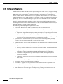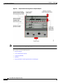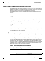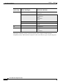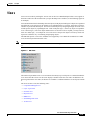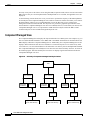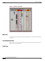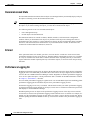
1
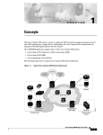
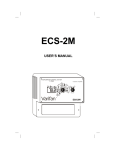
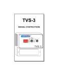
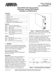
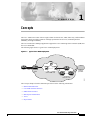
C H A P T E R
1
Concepts
The Cisco 10000 series router offers a single solution for leased–line, ATM, frame relay, and broadband
aggregation while providing customers with high–performance IP services, maximum platform
scalability, and high availability.
The Cisco 10000 Series Manager application supports the Cisco 10005 Edge Services Router (ESR) and
the Cisco 10008 ESR.
The following figure shows a typical Cisco 10000 deployment.
Figure 1-1
Typical Cisco 10000 Deployment
Leased
lines Cisco 10K
router
Service
provider
Cisco ATM core
89823
Cisco IP core
The Concepts chapter describes EM concepts and covers the following information:
•
EM Documentation Set
•
Cisco EMF Software Features
•
EM Software Features
•
EM Objects and Interfaces
•
Views
•
Object States
Cisco 10000 Series Manager User Guide
OL-3594-01
1-1
Chapter 1
Concepts
EM Documentation Set
EM Documentation Set
This guide is one part of the Cisco 10000 Series Manager EM documentation set. The following figure
displays all of the guides in the EM documentation set and details the contents of each.
EM Documentation Set
Cisco Element Management
Framework Installation and
Administration Guide (Release 3.2)
Cisco Element Management
Framework User Guide
(Version 3.2)
Cisco 10000 Series
Manager Installation Guide
(Release 1.0)
Cisco 10000 Series
Manager User Guide
(Release 1.0)
Describes how to install the Cisco Element Management Framework
application and provides additional setup and licensing information.
Describes how to use the Cisco Element Management Framework application.
Describes how to install the Cisco 10000 Series Manager
application and provides additional setup information.
Describes how to use the Cisco 10000 Series Manager application.
89785
Figure 1-2
The guides identified in the preceding figure are available from Cisco Systems. For further information
on obtaining Cisco documentation, see the “Obtaining Documentation” section on page -xv.
Cisco 10000 Series Manager User Guide
1-2
OL-3594-01
Chapter 1
Concepts
Cisco EMF Software Features
Cisco EMF Software Features
Cisco EMF provides a flexible framework which supports a variety of EMs, making it possible to
manage multiple device types within a given network on a single system. Common network management
functionality provides for complete management of the logical and physical components of the network.
Using a solid base, Cisco EMF provides vital core functionality which allows for optimal network
management when combined with EMs. Features include the following:
•
Map Viewer—Displays the contents of the managed device(s) and serves as the primary entry point
for the EM, allowing for enhanced object monitoring status for all network elements within the
managed network
•
Deployment templates—Provides object deployment prompts, increasing ease and consistency
•
Auto Discovery—Allows for the automatic discovery of devices entering the network based on IP
and/or SNMP data
•
Event Browser—Notifies the system of events (e.g., alarms) which occur on the managed network
and, in turn, notifies the network manager according to adjustable settings
•
Object Group Manager—Enables you to organize managed objects which relate to one another into
groups
•
Performance Manager—Presents performance statistics for monitored objects in a variety of formats
according to the criteria selected
•
User Access Control—Administration tool allowing system administrators to manage application
privileges per user and user passwords
•
Query Editor—Provides custom filtering capabilities which include or exclude certain information
from writing to the database and enables object group management
•
Notification Profiles—Warns the user of system events according to defined environmental
occurrences through an audible or visual indicators (e.g., beep, display pop–up window), scripts
(which, for example, sends an e–mail message), or event generation
•
Thresholding Regimes—Defines a set of polling attributes and the polling period for monitoring,
which, when met, run the applicable notification profiles
•
Event Groups—Organizes events by managed object(s) according to query settings
•
Database Management—Maximizes the Resource Manager Essentials (RME) tool to manage
database backup and restoration
For further information on Cisco EMF and the tools it provides, see the following items:
•
The “Cisco EMF Launchpad” section on page 2-6
•
The Cisco Element Management Framework User Guide Release 3.2
•
Cisco EMF help windows available through the Help button or menu on the Cisco EMF Launchpad
Cisco 10000 Series Manager User Guide
OL-3594-01
1-3
Chapter 1
Concepts
EM Software Features
EM Software Features
Installed with Cisco EMF, the EM allows for precise management of the device(s) it supports through
custom GUI windows and modeling behavior. Invoked from the Cisco EMF Map Viewer application, the
EM provides Fault, Configuration, Accounting, Performance, and Security (FCAPS) windows on
chassis, module, interface, and connection levels as applicable. These windows provide the features
which compliment the Cisco EMF capabilities to provide for complete, efficient network management.
Specifically, the Cisco 10000 Series Manager supports the Cisco 10005 ESR and Cisco 10008 ESR
chassis, as well as various modules which can accommodate ethernet, ATM, POS, SONET, and E3/DS3
interfaces. Element management capabilities for these items are provided in windows and wizards,
eliminating the need for operators to have detailed Cisco IOS software and SNMP–based knowledge for
individual interface or system parameter commands.
The following features highlight the capabilities of the EM:
•
Framework—Based on Cisco EMF 3.2, which includes FCAPS management tools
•
IOS Versions—See the corresponding release note document for specific versions supported
•
Deployment and Discovery—Allows for manual or automatic deployment and discovery
– Deployment—Supports manual deployment for generic objects, and pre–deployment of chassis
objects using templates which provide faster deployment with fewer errors
– Auto Discovery—Discovers chassis and all submodules automatically within a given IP range,
providing real–time information regarding the contents of the network
•
Synchronization—Synchronizes the physical inventory model with managed NEs, providing
accurate, real–time information on what is deployed in the network
•
Fault management—Provides status information, as well as fault detection, troubleshooting, and
repair tools
•
Configuration—Provides base configuration for managed objects within the device, as well as:
– Discovery—Allows for discovery of individual chassis and modules, or complete subchassis
discovery
– Preprovisioning—Enables configuration of predeployed modules not yet present in the chassis
on the device via IOS commands and within the EM through window–based features
– Restoration—Configuration backup functionality is available, enabling configuration
restoration as required
– Redundancy—Dual CPUs allow for fail–over backups and provide forced fail–over capabilities
when needed
– Profiles—Allows you to apply established configuration parameters to a bulk number of objects
•
Accounting—Provides real–time inventory information
•
Performance—Supplies real–time performance–related statistics as well as capabilities to log
historical performance data for analysis
•
Security—Provides capabilities to manage system security at the EM or device level
•
Alarm Notification—Provides support of multiple traps, producing alarm notification per the
criteria established
Cisco 10000 Series Manager User Guide
1-4
OL-3594-01
Chapter 1
Concepts
EM Objects and Interfaces
EM Objects and Interfaces
The EM manages both physical and logical objects as follows:
•
Physical—Represents tangible components and devices such as the chassis (hardware frame),
module interfaces and port adapters, and interfaces
•
Logical—Represents intangible, more abstract features, such as ATM connections objects and
profiles
Fault, Configuration, Accounting, Performance, and Security (FCAPS) windows are accessible on both
physical and logical EM objects, in the form of FCAPS menu options that appear when you right–click
on any object in the EM. FCAPS functionality provides a complete management interface to features of
the router.
The EM uses Telecom Graphics Objects (TGO) in the Map Viewer application. TGO is a
TeleManagement Forum (TMF) sponsored initiative to provide standard graphical representations for
network topology maps.
A TGO displays additional information icons on top of the existing object icons displayed in Map
Viewer. The additional icons indicate a variety of information (for example, information on the state of
the object or event status information). The following figure provides an example of a TGO.
Figure 1-3
Sample Telecom Graphical Object
An object is a representation of a network element. For example, the object could be a node, a shelf, a
shelf item, or a link. Each object shown in the right window provides pictorial cues which provide
information about its associated network element. The information can be structural information; for
example, a network element name or state and event information such as “out of service.”
Each object can display the following information about its associated network element:
•
Object name—Name that the user gives to the object
•
Object class—Class indicates a different kind of element
•
Object state—(ANSI T1-232):
– Event unacknowledged count
– Event unacknowledged state
– Event outstanding state
The following figure shows an example of a chassis map displaying a few of the TGO icons that could
appear.
Cisco 10000 Series Manager User Guide
OL-3594-01
1-5
Chapter 1
Concepts
EM Objects and Interfaces
Figure 1-4
Note
Sample Chassis Showing Telecom Graphical Objects
For additional information regarding the type of TGO objects that can appear in the EM, see the Cisco
Element Management Framework User Guide.
This section covers the following areas:
•
Physical Objects
•
Cisco 10000 Router Chassis
•
Supporting Modules
•
Modules
•
Physical Interfaces and Logical Interface Technologies
Cisco 10000 Series Manager User Guide
1-6
OL-3594-01
Chapter 1
Concepts
EM Objects and Interfaces
Physical Objects
The following table lists all physical objects created in the EM and the management functions that can
be performed on each object.
Table 1-1
Physical Objects and Management Functions
Physical Object
Management Functions
Chassis—The hardware frame of the Cisco , which houses all
subchassis objects (modules)
Fault
Configuration
Accounting
Processor Cards—The Cisco support router processor cards.
Fault
Configuration
Accounting
Performance
Modules—Modules may be either network. There are various types
of modules within a chassis (for example, ATM, Ethernet, and
Generic). Each of these modules support a given number of
physical interfaces (ports).
Fault
Configuration
Accounting
Performance
Physical Interfaces—Each module (interface or port adapter) has at Fault
least one, if not multiple, physical interfaces (ports). The type of Configuration
physical interface is equivalent to the type of module the interface Performance
resides on. Each different physical interface can support multiple
technologies (for details, see the “Physical Interfaces and Logical
Interface Technologies” section on page 1-11). The module type
determines what technologies reside on the interfaces.
Supporting Modules—Additional subchassis cards and modules,
including power supply module(s), processor module(s), and fan
tray modules. The EM supports the management functions to the
right on power supply and processor modules only.
Fault
Configuration
Performance
Accounting
The physical objects and interfaces in the preceding table are organized as follows:
•
The chassis contains the modules, including supporting modules (e.g., processors, power supplies,
and fan trays);
•
The modules contain the physical interfaces.
For further details on hierarchies within Cisco EMF and the EM, see the “Views” section on page 1-13.
Tip
Physical objects contained within a chassis are often referred to as subchassis objects or
modules.
Cisco 10000 Series Manager User Guide
OL-3594-01
1-7
Chapter 1
Concepts
EM Objects and Interfaces
Cisco 10000 Router Chassis
The Cisco 10000 Series Manager supports the Cisco 10005 Edge Services Routers (ESR) and
Cisco 10008 ESR. The supported Cisco 10000 series routers include a performance routing engine
(PRE), a point–to–point passive and redundant backplane, and redundant interface cards. With redundant
PREs, power supplies, and fans, the router is protected against any single–point of failure.
The following figures display the Cisco 10005 ESR and Cisco 10008 ESR chassis.
Figure 1-5
Cisco 10005 Chassis
The Cisco 10005 ESR chassis contains seven slots total, accommodating up to five line cards in the
upper compartment and up to two PRE cards in the lower compartment. The blower, located on the side
of the chassis (not identified in the preceding depiction), allows for side–to–side airflow to cool the
device.
Cisco 10000 Series Manager User Guide
1-8
OL-3594-01
Chapter 1
Concepts
EM Objects and Interfaces
Figure 1-6
Cisco 10008 Chassis
The Cisco 10008 ESR chassis contains ten slots overall. Two centrally located slots accommodate PRE
cards and eight slots accommodate line cards, four on either side of the PRE slots. Area for dual PEMs
provide redundant power supplies. The blower, located at the top of the chassis’ front view, allows for
front–to–back airflow to cool the device.
Supporting Modules
The EM supports the following types of supporting modules within a chassis. Some modules only apply
to certain chassis types.
•
SFC (Switch Fabric Card)
•
AC or DC Power Supply Module—Chassis can be ordered with either –48 VDC or 100 to 240 VAC
power supply modules.
•
Fan Tray—The fan tray circulates cooling air through the card cage in the chassis.
The EM does not provide for management of supporting modules.
Cisco 10000 Series Manager User Guide
OL-3594-01
1-9
Chapter 1
Concepts
EM Objects and Interfaces
Modules
The EM supports the following types of modules:
•
Processor—For a complete listing of the processor modules supported, see Table 1-2.
•
Generic—For a complete listing of the Generic module interfaces and port adapters the EM supports
see Table 1-3.
•
ATM (Asynchronous Transfer Mode)—For a complete listing of the ATM modules the EM supports
see Table 1-4.
•
Ethernet (Fast or Gigabit)—Fast Ethernet supports data transfer rates of 100 Mbps; Gigabit Ethernet
supports data transfer rates of 1000 Mbps (or 1 Gigabit). For a complete listing of the Ethernet
modules the EM supports see Table 1-5.
Table 1-2
Supported Processor Modules
Processor Module
Description
ESR-PRE
Performance routing engine line card
ESR-PRE1
Performance routing engine with ECC line card
Table 1-3
Supported Generic Modules
Module
Description
ESR-24CT1/E1
Twenty four port T1/E1 line card (not supported on a broadband
IOS system)
Table 1-4
Supported ATM/SONET Modules
Module
Description
ESR-4OC3-CHSTM-1
Four port channelized STM-1/STS3 line card
ESR-6CT3
6 port channelized T3 line card
ESR-1OC-12-ATM-SM
One port OC12 ATM line card
ESR-10C-12/P-SMI
One port OC12 POS line card
ESR-8DS3-E3
Eight port E3 or D3 line card
ESR-6OC-3/P-SMI
Six port OC3 POS line card
ESR-4OC3-ATM-SM
Four port OC3 ATM line card
Table 1-5
Supported Ethernet Modules
Module
Description
ESR-1GE
One port gigabit ethernet line card
Cisco 10000 Series Manager User Guide
1-10
OL-3594-01
Chapter 1
Concepts
EM Objects and Interfaces
Physical Interfaces and Logical Interface Technologies
Physical interfaces and logical interface technologies are modeled as objects below a parent module. As
mentioned before, the type of module characterizes the type of interface. Interface types further break
down into two categories, physical interfaces and logical interface technologies.
Physical interfaces are the ports which exist on line cards. This EM supports the following physical
interfaces:
•
Ethernet
•
SONET
•
DS1
•
DS3
The EM handles both SDH and SONET in the same manner. The routers support both SDH and SONET.
For a comparison chart of SONET and SDH speeds, see Appendix B, “SONET/SDH Conversion Chart.”
Logical interface technologies represent the communication between two network devices. Logical
interface technologies allow for virtual connections, such as PVCs and SPVCs. This EM supports the
following logical interface technologies:
•
ATM
•
IP
•
POS
Physical interfaces and logical interface technologies are classified as “interfaces” within this EM, and,
therefore, are referred to as such within this guide. Keep in mind the differences previously described as
you manage the interfaces within your network.
Tip
The technologies an interface supports are accessible within FCAPS–based management windows. It is
important to understand that physical interfaces require logical interface technologies in order to fully
manage an interface.
The following table outlines each interface type and the applicable physical and logical interface
technologies supported. Also included are the different FCAPS service windows that are applicable to
each physical and logical interface technology. For example, if you want to configure an ATM interface
type, look in the table under ATM, and you will notice that three physical interface and logical interface
technologies apply: ATM, SONET, and IP. This means that to fully configure an ATM over SONET
interface, for example, you should open and update the appropriate fields in all the physical and logical
configuration windows to completely configure a SONET interface which supports ATM technology.
Note that the shaded areas denote logical interface technologies.
Table 1-6
Physical Interfaces, Related Technologies and Windows
Interface Type
Physical and Logical
Interface Technologies
Ethernet
Ethernet
Configuration
Status
Performance
Profile
IP
Configuration
FCAPS Service Windows
Cisco 10000 Series Manager User Guide
OL-3594-01
1-11
Chapter 1
Concepts
EM Objects and Interfaces
Interface Type
Physical and Logical
Interface Technologies
SONET
SONET
Status
Performance
ATM
Fault
Configuration
Status
Performance
Profile
IP
Configuration
POS
Configuration
Profile
DS1
E1
Configuration
DS3
E3
Configuration
Status
Performance
FCAPS Service Windows
Although not technology–specific, physical or logical, generic support is available through
Configuration, Status, and Performance windows for each of the interface types in the preceding table.
Cisco 10000 Series Manager User Guide
1-12
OL-3594-01
Chapter 1
Concepts
Views
Views
Views are accessible by clicking the Viewer icon on the Cisco EMF launchpad. These views appear in
the frame at the left of the window when you open the Map Viewer window (see the following figure for
an example).
Views model hierarchical relationships between objects, both physical and logical. Objects are organized
into different views and can exist in multiple views simultaneously by reference. Each object can have
a number of parent and child objects. You can access EM objects by navigating through one of the views
to find specific objects by expanding the text. Click on the plus sign (+) next to any object to expand the
view. A minus sign (–) next to an object indicates there are no more levels to expand; you may, however,
click on a minus sign (–) to collapse the view to the level of the specific object as necessary. Each view
represents a different way of containing and grouping objects.
The EM adds specific views to the standard views supplied by Cisco EMF. The standard Cisco EMF
views are the Physical and Network views.
Note
For further information on views, see the Cisco Element Management Framework User Guide Release
3.2.
Figure 1-7
EM Views
The number in parenthesis next to a view indicates how many top–level objects are contained within the
view. Notice that the VLAN view does not display a number beside the view name. In addition to the
minus sign beside the view name, the absence of a number is a indicator that there are no objects beneath
it.
The Views section covers the following areas:
•
Component Managed View
•
Layer 3 QoS View
•
Network View
•
Physical View
•
RME View
•
Self Management View
•
VLAN View
Cisco 10000 Series Manager User Guide
OL-3594-01
1-13
Chapter 1
Concepts
Views
You may or may not see all of these views using this EM (exceptions noted). These views all exist within
EMs, however they are not all implemented. If multiple EMs are co–resident, the applicable views are
displayed.
As the following sections detail, the views you will use to perform the majority of the EM capabilities
are the Physical and Component Managed views. Both are similar in structure and allow you to initiate
the EM windows. However it is recommended that you use the Physical view to perform most
management functions within the EM. The Physical view provides a graphical representation of the
chassis that the Component Managed view does not. It should, however, be noted that you must use the
Component Managed view to see representative ATM connection objects within the EM as ATM
connection objects are not available through the Physical view.
Component Managed View
The Component Managed view displays all objects within the Cisco EMF system. For example, say you
have two different EMs installed in Cisco EMF: EM A and EM B. Information for both the EM A and
EM B display within the Component Managed view. Additionally, the Component Managed view also
displays ATM connections such as PVCs and SPVCs. Connection objects are not visible in any other
view. However, it is not recommended to work within this view unless you have multiple EMs installed.
The Component Managed view and Physical view have the same basic hierarchy structure, as shown in
the following figure. Note that the Physical view does not display logical ATM connections like the
Component Managed view does.
Figure 1-8
Hierarchy of Component Managed and Physical Views
Site
Supporting
modules
Line cards
Cisco chassis
Supporting
modules
Line cards
Cisco chassis
Supporting
modules
Line cards
Physical
interfaces
Physical
interfaces
Physical
interfaces
Logical connections
(PVC and SPVCs)
Logical connections
(PVC and SPVCs)
Logical connections
(PVC and SPVCs)
80564
Cisco chassis
Cisco 10000 Series Manager User Guide
1-14
OL-3594-01
Chapter 1
Concepts
Views
Cisco 10000 Series Manager does not support ATM connection management, therefore logical ATM
connection objects associated with the supported devices are not apparent in the Component Managed
view.
Layer 3 QoS View
The Layer 3 QoS view displays only Layer 3 QoS objects within the EM, such as the following:
•
Access Lists
•
Committed Access Rate (CAR) objects
•
Weighted Random Early Detection (WRED) objects
You can work within this view to create and configure Access Lists or CAR or WRED objects by
accessing the respective EM menus.
This version of the EM does not provide Layer 3 QoS support. Neither the Layer 3 QoS view nor the
respective menus are applicable.
Network View
This view displays all network devices within their relevant networks and subnets. The auto–discovery
system of Cisco EMF uses this view to determine which devices exist on the system so that it does not
try to discover the same device multiple times. For details on auto–discovery, see the “Automatically
Discovering Chassis” section on page 3-2.
Physical View
Objects in the Physical view are ordered according to their relative physical location. The Physical view
defines physical containment relationships, meaning that each object is defined according to which
object it is contained within. For example, a site is located under the Physical view; a chassis is contained
under a site; and sub modules and supporting modules are contained within a chassis.
See Figure 1-8 for an overview of the structure of the Physical view.
The Physical view also provides chassis maps, which are graphical representations of the chassis and its
contents. You can access management menus on objects within chassis maps. To display a chassis map,
simply click on the chassis object for the router you wish to view.
Cisco 10000 Series Manager User Guide
OL-3594-01
1-15
Chapter 1
Concepts
Views
Figure 1-9
Physical View Chassis Map
RME View
All objects managed by the RME server display beneath the RME view. Objects are organized by RME
server objects.
Self Management View
This view allows you to monitor network elements which are part of the Cisco EMF system. The Self
Management view is non–propagating.
VLAN View
Cisco 10000 Series Manager User Guide
1-16
OL-3594-01
Chapter 1
Concepts
Object States
Object States
Object states reflect the life cycle of an object. Whatever stage the object is in at any given time displays
in the state type. The state of an object can change frequently, depending upon what actions take place
on the object. All objects within the EM are in a specific state which appears at the bottom left corner
of each FCAPS window. The following figure highlights an object’s state.
Figure 1-10 EM Object States
The two most common object states are Normal and Decommissioned. For example, when you deploy a
module in the EM, the initial state of the module is decommissioned. You can then commission the
module to begin active management. (For instruction on how to commission a module, see the
“Commissioning Modules” section on page 3-35 or on page 5-28.) When you commission the module,
it passes through two transitory states: discovery, then commissioning. The commissioning process
determines which state to move the object into (typically Normal). This example reflects the basic
process of deploying and commissioning an object.
Certain states ripple down to objects below. For example, if you decommission a chassis, all subchassis
objects also decommission. If you enable performance logging on a module, all interfaces under the
module also enable.
By default, FCAPS windows refresh at a rate dependent upon the type of window. For example,
inventory windows refresh at a lower rate than performance windows. The average refresh rate is every
30 seconds.
The following sections describe the possible states that an object may be in and provides a description
of these states.
Normal State
The normal state indicates that an object is operational. When an object enters the normal state, the EM
performs heartbeat polling on objects at varying intervals to determine their presence and current state.
For instance, chassis presence polling occurs every minute while module and interface presence polling
occurs every five minutes.
Cisco 10000 Series Manager User Guide
OL-3594-01
1-17
Chapter 1
Concepts
Object States
Decommissioned State
The decommissioned state indicates that an object is not managed. When you manually deploy an object,
the object is normally put into the decommissioned state.
Tip
Manually deployed objects are initially decomissioned so you have the option of managing
the object. If you want to manage the object, you must first commission the object.
The following actions occur on a decommissioned object:
•
Active management stops
•
All sub objects also decommission
Decommission buttons are located in Chassis, Module, Interface, and Connection Configuration
windows. When you decommission an object, any children of that object also change their state to
decommissioned. For example, if you decommission a chassis, all objects within that chassis (modules,
interfaces, and connections) also decommission. If you decommission a module, all interfaces and
connections on that module decommission, and so on.
Errored
If the operational status of a module goes down, it moves into the errored state. In the errored state,
performance polling (if active) stops; however, heartbeat polling (which polls an object every 5 minutes
to verify its existence and current state) continues until the device responds positively to a heartbeat
request. When the module responds positively to heartbeat requests, it moves back into the previously
held state.
Performance Logging On
Enabling performance logging on for an object in the Normal state moves the object into the performance
logging on state. This means that performance data collection for the object begins and is available for
review in the Cisco EMF Performance Manager window. Regardless of whether performance logging is
on or off for a particular object, current performance data is available in the EM Performance windows
as Chapter 8, “Performance”, describes.
You can enable performance logging on a global scale or on an individual object basis. Enabling global
performance logging puts all subchassis objects into a performance logging on state.
Performance logging occurs every 15 minutes. This means that when you enable performance logging
or global performance logging initially on an object, at least one 15–minute increment must pass before
data displays in the Performance Manager.
Heartbeat polling occurs on objects in the performance logging on state. If the object moves into the
errored state, it returns to the performance logging on state when the error is rectified. For example, if a
module is in the performance logging on state and it goes down, it moves into the errored state. When
heartbeat polling finds that the module is back up, it restores the module to the performance logging on
state.
Cisco 10000 Series Manager User Guide
1-18
OL-3594-01
Chapter 1
Concepts
Object States
Lost Comms
The lost comms (lost communications) state indicates that the object is not responding to heartbeat
polling. The EM can apply this state to a chassis, module, or interface. When an object is in the lost
comms state, heartbeat polling occurs on the object. When the object responds to heartbeat polling, it
moves out of the lost comms state. For example, say an ATM module in the EM was predeployed. When
you perform device synchronization (commissioning a chassis), the ATM module is not yet physically
present in the hardware. In this situation, the EM places the ATM module into the lost comms state,
where it continues to poll for the presence of the module. When the ATM module is inserted into the
chassis, the EM detects its presence and moves the module out of the lost comms state and into a
respective state (typically normal).
Lost Comms No Poll
The lost comms (lost communications) no poll state occurs when the router is not contactable. When the
EM loses connectivity with a device, the representative chassis object remains in the lost comms state
so that heartbeat polling continues on the chassis. However, all modules and interfaces within that
chassis move into a lost comms no poll state. There is no point in polling modules and interfaces within
a device that is not contactable. If the connection with the device is down, all modules and interfaces
will be down. When the device becomes contactable again, the chassis, modules, and interfaces are
moved out of the lost comms no poll state.
Discovery Lost Comms
The discovery lost comms state occurs only during subchassis discovery. If, for example, you
commission a chassis (which begins the process of subchassis discovery) and a module discovers with a
faulty connection, the module goes into the discovery lost comms state. When connectivity establishes
with the corresponding object in the device, subchassis discovery resumes, and the object moves out of
the discovery lost comms state.
Mismatched
The mismatched state occurs when a mismatch is found between what hardware is in the device and that
which is deployed in the EM. For example, assume a chassis has been deployed and commissioned. If
the chassis cards are switched with a different card type, the EM finds a mismatch. The chassis is put
into the mismatch state and a major alarm is raised.
To rectify a mismatch problem, first you must assess the source of the problem. If the operator was at
fault and predeployed an incorrect module, the operator should delete the predeployed module and
re–deploy the correct module. If the person who inserted the module is at fault because they inserted the
wrong type of module into the chassis, the module should be removed. When you remove a module, the
EM moves the module into a lost comms state. Inserting the correct module enables the EM to find the
new module and download the correct pre–deployment and offline configuration information, then
places the module into its respective state (typically normal).
Mismatch can also occur on a chassis. If, during deployment of a chassis, an incorrect IP address is
entered, the EM cannot discover the chassis due to an erroneous IP address that was entered during the
commissioning process. Because of this, discovery fails, a major alarm is raised against the chassis, and
Cisco 10000 Series Manager User Guide
OL-3594-01
1-19
Chapter 1
Concepts
Object States
the chassis enters the mismatched state. To rectify this problem, you must either delete the predeployed
chassis and deploy the correct one, or fix the IP address by re–entering the correct one in the chassis
Management Information window.
Preprovisioned
Module preprovisioning is available within the EM and device. Module preprovisioning essentially
serves as a way to establish place holders for anticipated or expected hardware modules.
Using the EM, modules may be preprovisioned on the chassis map by way of predeployment and
commissioning. Module predeployment occurs through manual deployment where the module type and
slot number are indicated. Representative objects display within the EM, allowing for module
configuration before the physical module is present in the device. Module preprovisioning occurs on the
device when manually deployed, or predeployed, modules which are not yet present in the device are
commissioned. Modules can also be preprovisioned upon predeployment if the card is not present and
the object is in a given state (normal, performance logging on, or synchronizing.)
Preprovisioned modules allow for configuration to occur in advance of the module being physically
in–place. Modules which have been predeployed and commissioned, either on the module level or
through subchassis discovery, enter the preprovisioned state. Preprovisioned modules appear on the EM
chassis map with double, or crisscrossed, hash marks.
Predeployed modules not yet commissioned (i.e., unprovisioned) remain in the decommissioned state.
Once preprovisioned modules are present within the device, all configuration parameters entered
through the EM or via IOS commands are applied to the card during discovery. Should the module which
was preprovisioned be different from that found in the device, the module moves to the mismatched state.
See the “Mismatched” section on the preceding page for additional information.
Transient Object States
Certain states in the EM are temporary or transient, that is, they exist only for a short time while a process
is underway. The following states are transient:
•
Download—Temporary state when a Cisco IOS Download is processing
•
Reset—Temporary state during a Cisco IOS Download, when the device reboots for the new image
to take effect
•
Discovery—Temporary state during subchassis discovery; objects are discovering during this stage.
Cisco 10000 Series Manager User Guide
1-20
OL-3594-01