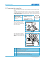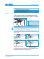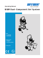
1
Operating Manual WIWA Dual-Component Gel System Type: ❍ 14025 R/F ❍ 25015 R/F Version with: ❍ Hopper ❍ Suction system Factory No. _ _ _ _ _ _ _ _ Translation of the original operating manual 1310_2KGel_IG002_DB_en •ski Contents Contents 1 Foreword.................................................................................................1-1 2 Safety.......................................................................................................2-1 2.1 Explanation of symbols..........................................................................2-1 2.2 Safety notes...........................................................................................2-3 2.2.1 Operating pressure......................................................................2-3 2.2.2 Risks caused by the injection pipe...............................................2-3 2.2.3 Risks caused by electrostatic charging........................................2-4 2.2.4 Explosion protection.....................................................................2-4 2.2.5 Health risks..................................................................................2-5 2.3 Information signs on the machine..........................................................2-5 2.4 Safety features.......................................................................................2-6 2.4.1 Safety valve..................................................................................2-7 2.4.2 Compressed air shut-off valve.....................................................2-7 2.4.3 Ground cable................................................................................2-7 2.5 Operating and maintenance personnel..................................................2-8 2.5.1 Machine owner’s duties................................................................2-8 2.5.2 Personnel qualification.................................................................2-8 2.5.3 Authorized operating personnel...................................................2-8 2.5.4 Personal Protective Equipment....................................................2-8 2.6 Notes on warranty..................................................................................2-9 2.6.1 Conversions and alterations.........................................................2-9 2.6.2 Spare parts...................................................................................2-9 2.6.3 Accessories..................................................................................2-9 2.7 Emergency procedures........................................................................2-10 2.7.1 Shutting down and depressurising the machine........................2-10 2.7.2 Leakages....................................................................................2-10 2.7.3 Injuries........................................................................................2-10 3 Machine Description...............................................................................3-1 3.1 Intended use..........................................................................................3-1 3.2 Machine structure..................................................................................3-1 3.2.1 Injection system with mounting kit for suction system..................3-2 3.2.2 Injection system with mounting kit for hopper..............................3-3 3.3 Compressed air connection...................................................................3-4 3.4 Mixing unit..............................................................................................3-5 Original operating manual 14025 + 25015 1310_2KGel_IG002_BAoDB_en •ski Contents 4 Transportation, installation and assembly...........................................4-1 4.1 Transportation........................................................................................4-1 4.2 Installation location................................................................................4-1 4.3 Assembly...............................................................................................4-2 4.3.1 Mounting the material hose and the mixing unit...........................4-3 4.3.2 Mounting the flushing agent hose................................................4-4 4.3.3 Connecting the compressed air supply........................................4-4 4.3.4 Grounding the machine................................................................4-4 5 Operation.................................................................................................5-1 5.1 Commissioning the machine..................................................................5-1 5.1.1 Put the feed pump into operation.................................................5-2 5.1.2 Cleaning the machine..................................................................5-2 5.1.3 Filling the system with processing material and bleeding it.........5-2 5.2 Injecting.................................................................................................5-3 5.3 Flushing.................................................................................................5-4 5.3.1 Flushing the components that have come into contact with mixed material........................................................................................5-4 5.3.2 Flushing the complete machine...................................................5-4 5.4 Interruptions to work..............................................................................5-5 5.5 Pressure relief........................................................................................5-5 5.6 Complete cleaning.................................................................................5-5 5.7 Material change.....................................................................................5-6 5.8 Decommissioning..................................................................................5-7 5.9 Replacing the mounting kits...................................................................5-7 5.10 Disposal...............................................................................................5-7 6 Maintenance............................................................................................6-1 6.1 Regular inspections...............................................................................6-1 6.2 Maintenance plan..................................................................................6-2 6.3 Flushing pump.......................................................................................6-2 6.3.1 Check condition of release agent.................................................6-2 6.3.2 Checking the release agent for material residue..........................6-2 6.4 Recommended operating materials.......................................................6-3 7 Remedying operating faults..................................................................7-1 0-4 Original operating manual 14025 + 25015 1310_2KGel_IG002_BAoDB_en •ski Contents 8 Technical data.........................................................................................8-1 8.1 Machine card .........................................................................................8-1 8.2 Type plate..............................................................................................8-2 8.3 Type designation....................................................................................8-2 Original operating manual 14025 + 25015 1310_2KGel_IG002_BAoDB_en •ski Foreword 1 Foreword Dear Customer! We are delighted that you have decided to purchase a dual-component gel system from our company. This operating manual is intended for the operating and maintenance personnel. It contains all the information required to working with this machine. The owner of the machine must ensure that operators and maintenance personnel always have an operating manual at their disposal in a language that they understand! Safe and reliable operation of the machine requires further information in addition to this operating manual. You should have read and understood the guidelines and accident prevention regulations that apply in your country. In Germany, these are as follows: ➤➤ ZH 1/406 “Richtlinien für Flüssigkeitsstrahler” (Guidelines for Liquid Jets), published by the German “Hauptverband der Gewerblichen Berufsgenossenschaften”; ➤➤ BGR 500, Chapter 2.29 “Application of Coating Materials”; ➤➤ BGR 500, chapter 2.36 “Working with Fluid Spraying Equipment” published by the employers liability insurance association for the gas, remote heating and water management sectors. We strongly recommend adding all relevant guidelines and accident prevention instructions to this operating manual. Moreover the manufacturer’s instructions and guidelines for coating or feeder materials must be respected at all times. However, if you have any questions, please do not hesitate to contact us. Best wishes for good results with your dual-component gel system from WIWA Wilhelm Wagner GmbH & Co. KG Copyright © 2013 WIWA This User Guide remains the copyright of WIWA Wilhelm Wagner GmbH & Co. KG. Gewerbestr. 1-3 • 35633 Lahnau • Germany Tel.: +49 6441 609-0 • Fax.: +49 6441 609-50 • E-mail: [email protected] • Internet: www.wiwa.de This operating manual is solely intended for personnel involved in preparation, operation and servicing. It is prohibited to pass on this operating manual for reproduction, utilisation or communication of its contents, unless this has been explicitly permitted. Infringements incur an obligation to pay damage compensation. All rights reserved in the event of registration of the patented design, industrial design or registered design. This operating manual only applies in conjunction with the machine card that was given to you with the user manual for your machine. Please check that the data on the type plate match those on the machine card. Please notify us immediately if there are discrepancies, if the user manual has been incorrectly compiled or if the type plate is missing. 1-1 Original operating manual 14025 + 25015 1310_2KGel_IG002_BAoDB_en •ski Safety 2 Safety This machine has been designed and manufactured under due consideration of all safety-related aspects. It complies with the current standard of technology and the valid accident prevention instructions. The machine left the factory in perfect condition and guarantees a high level of technical reliability and safety. Nevertheless, there are certain risks that can arise from incorrect operation or misuse: ➤➤ to life and limb of the operator or third party, ➤➤ to the machine and other material assets of the owner, ➤➤ to the efficient working capacity of the machine. You must refrain from any working methods that could affect the safety of operating personnel and equipment. All the people that are involved in set-up, commissioning, operation, maintenance, repair and servicing of the spray gun must have read and understood the operating manual beforehand, especially the chapter entitled “Safety”. Your safety is at stake! We recommend to the owner of this unit to have this confirmed in writing. 2.1 Explanation of symbols Safety information warns you of potential risks of accidents and tell you the measures that are needed to prevent accidents. In WIWA operating manuals, safety information is specially highlighted and marked as follows: DANGER Indicates danger of accidents; if you ignore the safety notes, there is a high risk of severe injury resulting up to and including death! WARNING Indicates danger of accidents; if you ignore the safety notes, severe injury can result up to and including death! CAUTION Indicates danger of accidents; if you ignore the safety notes, severe injury can result! Indicates important information on correct use of the machine. Ignoring it can result in damage to the machine or in its vicinity. Original operating manual 14025 + 25015 1310_2KGel_IG002_BAoDB_en •ski 2-1 Safety In the safety notes about the risk of accidents, different pictograms are shown after each hazard source - examples: General accident risk Risk of explosion from explosive atmosphere Risk of explosion from explosive substances Danger of injury due to electric voltage or electrostatic charging Risk of crushing by moving machine parts Risk of burning due to hot surfaces Mandatory safety instructions concern protective gear to be worn in the first instance. They are particularly highlighted and marked as follows: Wear protective clothing Highlights the order to wear the prescribed protective clothing to protect against skin injuries caused by spraying material or gases. Use eye protection Indicates the requirement to wear protective goggles to protect against eye injuries caused by gases, fumes or dust. Wear ear defenders Indicates the requirement to wear ear defenders to prevent your hearing from being damaged by noise. Use a respiratory protection mask Highlights the order to use a respiratory protection mask to prevent your respiratory tract from being damaged by gases, fumes or dusts. Wear protective gloves Highlights the order to wear protective gloves with lower arm protection to protect against burn injuries caused by heated materials. Wear protective footwear Highlights the order to wear protective footwear to prevent injuries to the feet due to objects that may fall, drop or roll around or to hot or caustic liquids. Indicates references to guidelines, work instructions and operating manuals that contain important information which you must observe at all times. 2-2 Original operating manual 14025 + 25015 1310_2KGel_IG002_BAoDB_en •ski Safety 2.2 Safety notes Please remember that the machine works at high pressure and may cause life-threatening injuries if used inappropriately! Always observe and follow all instructions in this operating manual and in the separate operating manuals of individual machine parts and/or the optionally available accessory devices. The accident prevention instructions “Application of Coating Materials” (BGR 500, chap. 2.29) and the guidelines for liquid jets ZH1/406 of the employer’s liability insurance association must strictly be complied with. 2.2.1 Operating pressure WARNING Components that do not comply with the maximum permissible operating pressure can burst and cause serious injury. ➤➤ The specified maximum operating pressures must generally be complied with for all components. In case of varying operating pressures, the lowest value is always the one to be taken as the maximum operating pressure for the entire machine. ➤➤ Material hoses and hose assemblies must comply with the maximum working pressure, including the required safety factor. ➤➤ Material hoses must be leak tight and free of kinks, signs of abrasion or bulges. ➤➤ Hose connections must be tight. 2.2.2 Risks caused by the injection pipe WARNING The material is discharged from the mixing unit under very high pressure. Due to its cutting effect the spray jet can cause severe injuries by penetrating the skin or entering into the eyes. ➤➤ Never point the mixing unit at yourself, other people or animals. ➤➤ Do not hold your fingers or hands in front of the mixing unit! ➤➤ Do not reach with your hands into the material jet. WARNING Unintentional material release from the mixing unit may cause personal injury or damage to property. ➤➤ Every time you stop work, always close all the levers on the mixing unit. ➤➤ Before carrying out commissioning, always check that the mixing unit is functioning correctly. Original operating manual 14025 + 25015 1310_2KGel_IG002_BAoDB_en •ski 2-3 Safety 2.2.3 Risks caused by electrostatic charging WARNING The high flow velocities associated with the injection method may cause electrostatic charging. Static discharges can cause fire and explosion. ➤➤ Make sure that the machine is earthed correctly! ➤➤ Always use open containers that are electrically conductive! ➤➤ Stand the containers on a grounded surface. ➤➤ Never pump cleaning agent or materials that contain cleaning agent into cone-top cans or drums with bungholes! ➤➤ When using metal containers always ensure that the mixing unit is in contact with the container wall. ➤➤ Only use conductive material hoses. All original material hoses from WIWA are conductive and perfectly adapted to our equipment. WARNING If the machine is contaminated by coating material during spraying, the increase in the coating thickness can lead to static charging. Static discharges can cause fire and explosion. ➤➤ Clean the machine from contamination due to coating material immediately. ➤➤ Carry out cleaning work outside areas subject to explosion hazards. 2.2.4 Explosion protection WARNING Machines that are designed without explosion protection must not be used in workshops that come under the explosion protection ordinance. Explosion-protected machines meet the explosion protection requirements of Directive 94/9/EC for the explosion group, unit category and temperature class specified on the type plate or in the declaration of conformity. The operator is responsible for determining the zone allocation according to the Directive of EC 94/9/EC, Appendix II, no. 2.1-2.3 when observing the measures of the responsible inspecting authority. The operator is responsible for checking and ensuring that all technical data and markings according to ATEX correspond with the necessary requirements. Please note that several components have their own type plate with separate marking according to ATEX. In this case the lowest explosion protection of all attached markings applies for the entire machine. Applications where the malfunction of the unit can lead to danger to personnel must be provided with respective safety measures by the operator. 2-4 Original operating manual 14025 + 25015 1310_2KGel_IG002_BAoDB_en •ski Safety However, if agitators, heaters or other electrically accessories are additionally mounted, one must check the explosion protection. Plugs for heaters, agitators, etc. that do not have explosion protection, may only be plugged in outside of areas that fall under the explosion protection ordinance, even if the accessory equipment as such is explosion protected. 2.2.5 Health risks Follow the safety notes and dosing information of the manufacturer and the generally applicable regulations when handling paints, cleaning agents, oils, greases and other chemical substances. CAUTION Depending on the materials being applied, solvent vapours may result that can cause damage to health and property. ➤➤ Always ensure sufficient aeration and ventilation at the workplace. ➤➤ Always observe the processing instructions issued by the material manufacturers. When cleaning your skin, use only appropriate skin protection, skin cleaning and skin care products. In closed or pressurized systems dangerous chemical reactions may occur if parts made of aluminium or galvanized parts come into contact with 1.1.1 trichloroethane, methylene chloride or other solvents containing halogenated hydrocarbons (CFC’s). If you want to process materials containing the afore mentioned substances, we recommend to consult the material manufacturer to clarify the usability of such substances. For these materials, we have available a range of rust- and acid-proof machines. 2.3 Information signs on the machine Information signs attached to the machine, like safety information, refer to possible danger areas and must be strictly observed. They must not be removed from the machine. Damaged and illegible information signs must be replaced immediately. Apart from this you should also read and follow the safety notes in the operating manual. Original operating manual 14025 + 25015 1310_2KGel_IG002_BAoDB_en •ski 2-5 Safety 2.4 Safety features WARNING If one of the safety features is missing or not fully functional, the operating safety of the machine cannot be guaranteed! ➤➤ If you discover any faults in the safety features or other deficiencies on the machine, stop operation of the machine immediately. ➤➤ Only resume operation of the machine after the fault has been completely eliminated. Safety features must be checked with the machine depressurized: ➤➤ before initial commissioning, ➤➤ always before starting work, ➤➤ after set-up work, ➤➤ after all cleaning, servicing and repair work. Check list: 55 Lead seal on the safety valve still intact? 55 Safety valve free of external damage? 55 Function of compressed air shut-off valve correct? 55 Are the ball valves and the one-hand lever on the mixing block functioning correctly? 55 Ground cable free of damage? 55 Are the ground cable connections on the machine and the conductor in good condition? The machine is equipped with the following safety features: ➤➤ A safety valve on the metering pump and the flushing pump ➤➤ Compressed air shut-off valve ➤➤ Ground cable 2-6 Original operating manual 14025 + 25015 1310_2KGel_IG002_BAoDB_en •ski Safety 2.4.1 Safety valve The safety valve prevents the maximum permissible air inlet pressure from being exceeded. The safety valve will open and vent off air when the air inlet pressure exceeds the set limiting value. There is one safety valve on the machine: ➤➤ in the air motor of the metering pump ➤➤ on the air motor of the flushing pump WARNING If the maximum permissible air inlet pressure is exceeded, components may burst. This may result in damage to persons and property. ➤➤ Never allow the machine to run without a safety valve or with a defective one! ➤➤ If the safety valve needs to be replaced, you can find the corresponding order number on the machine card. ➤➤ With new safety valves, ensure that they have been set to the maximum permissible air inlet pressure of the machine (see type plate/ machine card) and sealed with a lead seal. 2.4.2 Compressed air shut-off valve The compressed air shut-off valve on the metering pump interrupts the air supply to the entire machine; when closed, this valve prevents the machine from starting up in an uncontrolled way. Apart from this, there is a compressed air shut-off valve on the flushing pump that you can use to interrupt the compressed air supply to just this pump. Principle of function: ➤➤ Open in the direction of flow, see Fig. 1 ➤➤ Close across the direction of flow open closed Fig. 1 Compressed air shut-off valve “OPEN” The functional principle of all the air pressure regulators that are installed on the machine is identical: After the air supply has been cut off, the machine is still under pressure. Before starting maintenance and repair work, this means that you must completely discharge the pressure! 2.4.3 Ground cable Original operating manual 14025 + 25015 1310_2KGel_IG002_BAoDB_en •ski To prevent electrostatic charging, you must ground the machine to n electrically conductive object using the ground cable (see Chapter 4.3.4 “Grounding the machine” on page 4-4). If the ground cable is defective or you lose it, please order a replacement immediately (Order Number 0474487)! Fig. 2 Ground cable 2-7 Safety 2.5 Operating and maintenance personnel 2.5.1 Machine owner’s duties The machine owner: ➤➤ is responsible for the training of the operating and maintenance staff, ➤➤ must instruct the operating and maintenance staff in correct handling of the machine as well as in wearing the correct work clothing and personal protective equipment, ➤➤ must make aids available to the operating and maintenance personnel like lifting equipment for transporting the machine or containers, for example. ➤➤ must make the user manual available to the operating and maintenance staff and ensure that it always remains available, ➤➤ must ensure that the operating and maintenance staff have read and understood the user manual. Only then may the machine be brought into service. 2.5.2 Personnel qualification A differentiation is made between two groups of people in dependence on their qualifications: ➤➤ Instructed operators have been verifiably instructed by the machine owner in the activities they are tasked with and the potential risks connected with them in the case of incorrect behaviour. ➤➤ Trained personnel have been instructed by the machine builder such that they are capable of carrying out maintenance and repair work on the system and recognising potential risks on their own initiative and of avoiding these risks. 2.5.3 Authorized operating personnel Activity Qualification Setup and operation Instructed operator Cleaning Instructed operator Servicing Trained personnel Repair Trained personnel Juveniles under the age of 16 are not allowed to operate this machine. 2.5.4 Personal Protective Equipment Wear protective clothing Always wear the protective clothing specified for your work environment (e.g. antistatic protective clothing in areas subject to explosion hazards) and also follow the recommendations in the safety data sheet issued by the material manufacturer. 2-8 Original operating manual 14025 + 25015 1310_2KGel_IG002_BAoDB_en •ski Safety Use eye protection Wear protective goggles to protect against eye injuries caused by material splatter gases, fumes or dust. Wear ear defenders Operating personnel should be provided with suitable noise protection equipment. The machine operator is responsible for adhering to the accident prevention regulation “Noise” (BGV B3). For this reason, pay special attention to the conditions at the installation location – the noise burden, for example, will increase if the system is installed in or on hollow bodies. Wear a respiratory protection mask We strongly recommend that you wear a respiratory protection mask, even though the paint mist has been minimized in the airless spray painting method given a correct pressure setting and correct working methods. Wear protective gloves Always wear antistatic protective gloves to prevent your skin coming into direct contact with the material being processed. When processing heated materials, you must wear lower arm protection in addition to protective gloves to prevent burns. Wear protective footwear Wear antistatic protective footwear to prevent injuries to the feet due to objects that may fall, drop or roll around and to prevent slipping on a slippery floor. 2.6 Notes on warranty 2.6.1 Conversions and alterations ➤➤ Unauthorized conversions or alterations should not be undertaken on safety grounds. ➤➤ Protective equipment should not be dismantled, converted or bypassed. ➤➤ The machine must only be operated within the specified limiting values and machine parameters. 2.6.2 Spare parts ➤➤ When carrying out maintenance and repair work, you must only use WIWA original spare parts. ➤➤ Use of components which have not been manufactured or delivered by WIWA renders any warranty null and void. 2.6.3 Accessories ➤➤ Using original WIWA accessories guarantees that they are usable in our machines. ➤➤ If you use third-party accessories, they must be suitable for the machine – particularly with regard to the operating pressure, the electrical connection data and the connection sizes. WIWA accepts no liability for damage or injuries resulting from the use of these parts. Original operating manual 14025 + 25015 1310_2KGel_IG002_BAoDB_en •ski 2-9 Safety ➤➤ You must observe the safety regulations of the accessories. These safety regulations are found in the separate operating instructions for the accessories. 2.7 Emergency procedures 2.7.1 Shutting down and depressurising the machine In an emergency, immediately shut down the machine and depressurize it. 1. Close the compressed air shut-off valve. 2. Operate the one-hand lever on the mixing unit again for a moment to relieve any residual flushing pressure so that the pressure in the entire system has been relieved. CAUTION The machine has not been flushed. The material in the machine can harden and clog it up. ➤➤ This procedure is not suitable for decommissioning (for more information on this topic, see Chapter 5.8 “Decommissioning” on page 5-7). ➤➤ After remedying the emergency, you must flush the machine (see Chapter 5.3 “Flushing” on page 5-4). Pay attention to the potlife of the material used. 2.7.2 Leakages WARNING In case of leakages material can escape under very high pressure and cause serious bodily injuries and material damage. ➤➤ Immediately shut down the machine and depressurize it. ➤➤ Retighten any screw fittings and replace defective components (only by trained personnel). ➤➤ Do not try to seal leaks on the connections and high-pressure hoses with the hand or by wrapping fabric around them. ➤➤ Do not repair material hoses! ➤➤ Before recommissioning the machine, check the hoses and screw fittings for leaks. 2.7.3 Injuries 2-10 If injured by processing materials or cleaning agents, always have available the safety data sheet (address, phone number, material designation and material number of the supplier or manufacturer) for the attending physician. Original operating manual 14025 + 25015 1310_2KGel_IG002_BAoDB_en •ski Machine Description 3 Machine Description The 14025 and 25015 Dual-Component Gel Systems are pneumatically operated dual-component high-pressure injection systems. The mixing ratio of these machines is fixed with the output being between 80-144 cm3 per double stroke. depending on the system type. Metering pumps feed the components to a mixing unit. As an option, the systems can be equipped with a flushing pump and/or a mixing unit. The flushing agent pump allows you to immediately flush all the components that have come into contact with the mixed material. The mixing unit is an external one and is available with different coupling pieces for connecting the packer. For details of you machine’s technical data, refer to the attached machine card and/or Chapter 8 “Technical data” on page 8-1. 3.1 Intended use The dual-component gel system is intended for use in building refurbishment, including amongst other things for sealing cracks and applying moisture barriers. You can only use it to process water-based acrylate gels and silicate injection materials. Depending on customer requirements, two versions are available: ➤➤ A dual-component gel system with a mounting kit for a suction system This machine is only suitable for processing low-viscosity materials with components “A” and “B” having to have virtually the same viscosity. ➤➤ A dual-component gel system with a mounting kit for a filling hopper Using this machine, it is possible to process high-viscosity materials with different viscosities. Any other use is considered to be unintended. If you intend to use the machine for other purposes or with other materials and thus not for the purpose for which it is intended, you must ask WIWA for permission – otherwise the warranty will be invalidated. Intended use also includes compliance with the technical documentation and adherence to the prescribed operating, servicing and maintenance guidelines. 3.2 Machine structure Two variants of the dual-component gel system can be supplied that differ by virtue of their outputs. ➤➤ The 14025 has a free-flow output of up to 14 l/min ➤➤ The 25015 has a free-flow output of up to 14 l/min It is possibly to optionally fit each system type with a mounting kit either for suction systems or for filling hoppers. Both mounting kits are interchangeable at any time. Depending on the machine type, a flushing pump is mounted on the frame. Original operating manual 14025 + 25015 1310_2KGel_IG002_BAoDB_en •ski 3-1 Machine Description Material hoses are connected to the pumps’ material outlets as well as to the external mixing unit. As standard, all the machine’s components are mounted on a common cart. 3.2.1 Injection system with mounting kit for suction system 1 2 7 3 4 8 9 5 6 10 11 12 Fig. 3 Front and rear view No. Designation 1 Cart 3 Air motor (metering pump) 2 4 5 6 7 8 9 10 11 12 3-2 Air supply system Ground cable Material pump for component B Material pump for component A Flushing pump (optional) Material pressure display for component A Material pressure display for component B Flushing agent suction system (with flushing pump version only) Suction system for component A Suction system for component B Original operating manual 14025 + 25015 1310_2KGel_IG002_BAoDB_en •ski Machine Description 3.2.2 Injection system with mounting kit for hopper 1 6 2 3 4 5 7 8 9 10 Fig. 4 Front and rear view No. Designation 1 Cart 3 Ground cable 2 4 5 6 7 8 9 10 Original operating manual 14025 + 25015 1310_2KGel_IG002_BAoDB_en •ski Compressed-air regulator Filling hopper for component A Filling hopper for component B Air motor (metering pump) Material pressure display for component B Material pressure display for component A Material pump for component B Material pump for component A 3-3 Machine Description 3.3 Compressed air connection Here, you make the connection of the compressed air hose provided by the owner. Using the compressed air shut-off valve, you open or close the compressed air supply for the entire machine. There are separate air pressure regulators for the metering pumps and the flushing pump. You can read off the pressure on the pressure gauges. The functional principle ➤➤ Turn the adjusting screw of all the air pressure clockwise to increase the regulators that are pressure, installed on the machine ➤➤ Turn the adjusting screw is identical: anti-clockwise to die reduce the pressure. Dual-component gel systems without a flushing pump are fitted with an air pressure regulator at the factory. Fig. 3.1 1 2 3 4 5 Fig. 5 Compressed-air regulator Dual-component gel systems with a flushing pump are fitted with an air supply system at the factory. 1 8 7 6 4 2 3 5 Fig. 6 Air supply system No. Designation 1 Pressure gauge for metering pumps 3 Compressed air connection for compressed air supply provided by the owner 2 4 5 3-4 Compressed air shut-off valve Air pressure regulator for metering pumps Compressed air connection for metering pumps Original operating manual 14025 + 25015 1310_2KGel_IG002_BAoDB_en •ski Machine Description No. Designation 6 Air pressure regulator for flushing pump 8 Pressure gauge for flushing pump 7 3.4 Mixing unit Compressed air connection for flushing pump The dual-component gel system is optionally available with a mixing unit. There are three levers on the mixing unit that you can use to set the “Inject”, “Flush” or “Stop” operating modes. 1 No. Designation 1 INJECT/STOP one-hand lever 3 Ball valve for FLUSHING “B” 2 2 3 4 4 Ball valve for FLUSHING “A” Static mixer Fig. 7 external mixer unit You can extend the lifetime of the ball valves on the mixing unit if you ➤➤ do not switch the levers over under pressure ➤➤ if you always push the levers to the end stop of the desired position. Operating modes: Fig. 8 Inject “Open” Fig. 9 Inject “Stop” Fig. 10 Flush component A “Open”, Flush component B “Closed” Fig. 11 Flush component B “Open”, Flush component A “Closed” Alternately open and close the flushing levers several times during flushing to ensure that each component is flushed separately. Finally, open both flushing levers. Original operating manual 14025 + 25015 1310_2KGel_IG002_BAoDB_en •ski 3-5 Transportation, installation and assembly 4 Transportation, installation and assembly The machine left the factory in flawless condition and was appropriately packed for transportation. Check the machine on receipt for any damage in transit and for completeness. 4.1 Transportation Please follow these notes when transporting the machine: ➤➤ Ensure sufficient load bearing capacity of lifting gear and lifting tackle when loading the machine. You will find the dimensions and weights of the machine on the machine card. ➤➤ Use only appropriate transport vehicles with sufficient load bearing capacity. ➤➤ The machine must only be lifted by the lifting and lashing points provided for this purpose. Never lift the machine using the eye hook that may be present on a mounted pump or another accessory. These transportation aids are only rated for the mounted part and not for the entire weight of the machine including the attached parts. ➤➤ Do not transport any other objects (e.g. material drums) while lifting or loading the machine. ➤➤ Never stand under suspended loads or inside the loading area. There is a risk of death! ➤➤ Secure the load on the transport vehicle against slipping and falling off. If the machine was already operated, please observe the following: ➤➤ Disconnect the entire system power supply – even for short transportation distances. ➤➤ Empty the machine before transportation – fluid residues may escape during transportation despite this measure. ➤➤ Remove all loose components (e.g. tools) from the machine. ➤➤ Assemble the parts or fittings dismantled for transport purposes before start up and in compliance with the intended use of the system. 4.2 Installation location The machine can be installed indoors and out of doors. However, outdoor installation should be preferred in order to avoid contamination. Set the machine up horizontally on a foundation that is flat, firm and vibration-free. The machine must not be tipped or on an incline. Ensure that all the operating elements and safety features are easy to reach. 4-1 Original operating manual 14025 + 25015 1310_2KGel_IG002_BAoDB_en •ski Transportation, installation and assembly WARNING If the machine is used outside during a thunderstorm, a lightning strike can cause a life-threatening situation for the operating personnel. ➤➤ Do not operate a machine out of doors during a thunderstorm! ➤➤ The machine owner must ensure that the machine is equipped with suitable lightning protection equipment. Safety measures at the place of installation: ➤➤ This machine requires a solid base and sufficient free space for safe operation. ➤➤ Always keep the working area, especially all walkways and standing areas, clean and tidy. Immediately remove any spilled material and cleaning agent. ➤➤ Always ensure adequate ventilation at the work place to avoid damage to health and material objects. You must guarantee an air change rate of 5. ➤➤ Always observe the processing instructions issued by the material manufacturers. ➤➤ Even though there are no legal directives for low-mist injection methods, all hazardous solvent vapours and paint particles should be extracted. ➤➤ Protect objects adjacent to the object from possible damage caused by the material mist. 4.3 Assembly WARNING If assembly work is carried out by people who have not been trained for this work, you endanger yourself and other people and impair the safety and reliability of the machine. ➤➤ Electrical components must only be mounted by trained time-served electricians – with all the other components, e.g. the material hose and the mixing unit being assembled by trained personnel only. Some system components are possibly packed separately for transportation. Please assemble these parts again before using the equipment for the first time. To ensure correct connection of the material hoses and the suction system, the markings below were applied to the system and the material hoses: Blue = component A Red = component B Yellow = flushing agent In all subsequent uses, you must keep to this assignment to avoid undesirable material reactions that lead to damage to the system. Original operating manual 14025 + 25015 1310_2KGel_IG002_BAoDB_en •ski 4-2 Transportation, installation and assembly 4.3.1 Mounting the material hose and the mixing unit If the machine was delivered with WIWA material hoses and a WIWA mixing unit, observe and comply with the information in this chapter. WARNING Components that do not comply with the maximum permitted operating pressure of the machine can burst and cause serious injury. ➤➤ Check the maximum permitted operating pressure of the material hoses and the mixing unit before assembly. This must be greater than or equal to the maximum operating pressure of the machine as specified on the type plate. WARNING If the hose couplings are subjected to tensile load, these assemblies may shear off. Material escaping under high pressure can cause injuries and material damage. ➤➤ If tensile loads on the hose couplings are to be expected (e.g. when moving the mixing unit), strain relief is needed! 1. Connect the material hoses to the material outlet of the associated material pump, see Fig. 12. When assigning components, pay attention to the colour markings. 2. Connect the material hoses to the mixing A B Fig. 12 Connecting material hoses unit see Fig. 13. A 3. Mount the coupling piece (see Fig. 14) for the packers on the mixing unit’s static mixer. Choose the coupling piece to match the type of packer you are using. Item 1 coupling G 1/4" I Item 2 mouth piece M10×1 IG Item 3 slide coupling M10×1 4-3 B Fig. 13 Connecting the mixing unit 1 2 3 Fig. 14 Coupling pieces for packers Original operating manual 14025 + 25015 1310_2KGel_IG002_BAoDB_en •ski Transportation, installation and assembly 4.3.2 Mounting the flushing agent hose Depending on the type of machine, the dual-component gel system is fitted with a flushing agent pump. 1. Mount the yellow flushing agent hose on the material outlet of the flushing pump, see Fig. 15. 2. Connect the other end of the hose to the Fig. 15 Connecting to the flushing pump manifold of the mixing unit, see Fig. 16. Fig. 16 Connecting to the mixing unit 4.3.3 Connecting the compressed air supply The compressor capacity must match the air requirements of the machine and the diameters of the air supply hoses must match the connections such that an adequate air supply is ensured. Operation with contaminated or moist compressed air causes damage to the machine’s pneumatic system. ➤➤ Use only dry dust- and oil-free air! 1. Make sure that ➤➤ ➤➤ all the air pressure regulators have been turned all the way back, the compressed air shut-off valve is closed. 2. Close the air hose on the compressed air connection of the air pressure regulator/the air supply system. 4.3.4 Grounding the machine WARNING The high flow velocities associated with the Airless spraying method may cause electrostatic charging. Static discharges can cause fire and explosion. ➤➤ Make sure that the machine and the object to be coated are earthed correctly! On delivery, the ground cable is already connected to the machine. To earth the machine, connect the terminal of the ground cable to an electrically conductive object outside the area at risk from explosion. Original operating manual 14025 + 25015 1310_2KGel_IG002_BAoDB_en •ski 4-4 Operation 5 Operation Before starting work, check if: 55 Are all the safety features present and fully functional? ➤➤ A safety valve ➤➤ Compressed air shut-off valve ➤➤ Ground cable 55 Are all machine parts tight? If required, tighten up these connections. Observe the technical notes of the respective material manufacturer. WARNING If material pumps run dry, the generated friction heat can cause fire or an explosion. ➤➤ Always make sure that the material drums do not run dry during operation. ➤➤ However, should this happen, stop the corresponding pump immediately and feed material. 5.1 Commissioning the machine Prerequisites: ➤➤ The machine must have been set up correctly and completely assembled. ➤➤ Do not start commissioning the machine unless you have the specified protective equipment. For more details, refer to Chapter 2.5.4 “Personal Protective Equipment” on page 2-8. ➤➤ The material to be processed must be available in sufficient quantity. In addition, you will need two suitable collecting vessels for excess material. These containers are not included in the scope of delivery. During commissioning, check that the machine or its individual components are leak-proof by slowly building up pressure. Overview of the work sequence for commissioning: 1. Put the feed pump into operation 2. Clean the machine 3. Fill the system with processing material and bleed it 5-1 Original operating manual 14025 + 25015 1310_2KGel_IG002_BAoDB_en •ski Operation 5.1.1 Put the feed pump into operation The flushing pump should always be ready for use while the system is being used so that all components coming into contact with the mixed material can be flushed within the pot life specified. You require: ➤➤ an open container of the cleaning agent that is needed for the material to be processed and that the material manufacturer recommends ➤➤ an additional collecting vessel for the cleaning agent that is flushed out. These containers are not supplied. 1. Set the mixing unit’s one-hand lever to “Stop” and connect the flushing ball valves on the mixing unit. 2. Make sure that all air pressure regulators have been fully regulated back. 3. Place the suction pipe of the flushing pump into the cleaning agent drum. 4. Open the compressed air shut-off valve. 5. Set the air pressure regulator of the flushing pump to a low pressure such that the pump starts up slowly. Regulate the flushing pump’s running speed to about 15 double strokes per minute. 6. As soon as you open the flushing ball valves on the mixing unit’s mixing block, the flushing pump starts working. When flushing, always aim the discharge outlet on the mixing unit’s static mixer into an empty container to be able to catch the mixture of material that is discharged. 5.1.2 Cleaning the machine After assembly, this machine was factory-tested for flawless function using a test substance. This means that at initial commissioning, you must perform complete cleaning to flush out any test medium residue. For more details, refer to Chapter 5.6 “Complete cleaning” on page 5-5. 5.1.3 Filling the system with processing material and bleeding it 1. Connect the material feed: ➤➤ ➤➤ With metering pumps that are supplied with material via a suction system, set the suction systems into the corresponding material containers of components A and B. With metering pumps that are supplied with material via a filling hopper, fill the material of components A and B into the corresponding filling hopper and if necessary open the stop cocks on the material inlet of the metering pumps. 2. Hold the mixing unit with the material being released towards the inner wall of the collecting vessel. 3. Set the one-hand lever of the mixing unit to “Inject”. 4. Start up the injection pumps slowly. To do this, regulate the air inlet pressure to about 1-2 bar. Original operating manual 14025 + 25015 1310_2KGel_IG002_BAoDB_en •ski 5-2 Operation 5. As soon as mixed material (components A and B) is discharged from the mixing unit, you have completed the filling and bleeding process. Set the one-hand lever of the mixing unit to “Stop”. The metering pumps are stationary! 6. To test the material reactions, fill a suitable vessel (containing about 0.2 l) with the material to be processed. To do this, repeat steps 3-5 in this chapter. 7. Immediately flush the mixing block until clean cleaning agent is dis- charged see Chapter 5.3.1 “Flushing the components that have come into contact with mixed material” on page 5-4. 5.2 Injecting Before injecting, you must have always commissioned the machine. (see Chapter 5.1 “Commissioning the machine” on page 5-1) The necessary packer nipples are attached in the location to be injected. 1. Regulate the air pressure regulator on the metering pump all the way back. 2. Set the one-hand lever of the mixing unit to “Stop”. 3. Connect the coupling piece on the mixing unit’s material outlet to the packer nipple. 4. Set the one-hand lever of the mixing unit to “Inject”. 5. Adjust a low air inlet pressure on the air pressure regulator for the metering pumps. Start injection at as low a pressure as possible to avoid endangering the safety of the operating personnel and the masonry. Now slowly increase the pressure to the desired operating pressure. 6. Set the one-hand lever of the mixing unit to “Stop” after the injection procedure is completed. While carrying out injection, keep an eye on the fill level of the material container. Topping up material in good time means that you can avoid the pumps sucking in air, which would make it necessary to bleed the system. 7. Within the potlife of the material used, change to the next packer and repeat steps 3-5 in this chapter. 8. Immediately after completing the last injection, flush the mixing block until clean cleaning agent is discharged. Always consider the potlife of the material used! 5-3 Original operating manual 14025 + 25015 1310_2KGel_IG002_BAoDB_en •ski Operation Checking the injection pressure: Check the function of both metering pumps by repeatedly opening and closing the one-hand lever on the injection lance. When doing this, pay attention to the material pressure display. ➤➤ Both pressure gauges must always show approximately the same values! If you close the one-hand lever during injection, both material pressure gauges will show the same dynamic pressure. When you open the one-hand lever again, the values must return to the operating pressure. Fig. 17 Material pressure display ➤➤ If this is not the case, immediately decommission the system and check the machine or contact WIWA’s customer service. 5.3 Flushing Always carry out flushing within the potlife of the material you are using as specified by the manufacturer. 5.3.1 Flushing the components that have come into contact with mixed material When interrupting work, flush all the components that have come into contact with the mixed material within the potlife specified by the manufacturer. 1. Hold the mixing unit with the material being released towards the inner wall of the collecting vessel. 2. Set the mixing unit’s one-hand lever to “Stop”. 3. Alternately open the flushing ball valves on the mixing unit until clean flushing agent is discharged. 4. Close the flushing ball valves on the mixing unit as soon as enough clean flushing agent has been discharged. The flushing agent pump is stationary! 5.3.2 Flushing the complete machine Flushing the complete machine is necessary: ➤➤ At initial commissioning To ensure that the spraying material is not negatively affected by the test medium that was used at the factory to test that the machine was functioning perfectly, you must flush the machine with cleaning agent. ➤➤ When changing material ➤➤ If work is interrupted and at decommissioning in the case of an interruption in spraying to flush spraying material out before it sets. To do this, proceed as described in Chapter 5.6 “Complete cleaning” on page 5-5. Original operating manual 14025 + 25015 1310_2KGel_IG002_BAoDB_en •ski 5-4 Operation 5.4 Interruptions to work 1. Set the one-hand lever of the mixing unit to “Stop”. The injection pumps are stationary. 2. Set the compressed air supply for the metering pumps all the way back. 3. Release the mixing unit from the packer nipple. 4. Hold the mixing unit laterally against the inner wall of a collecting vessel. 5. Relieve the material lines. To do this, briefly change positions of the onehand lever on the mixing unit between “Inject” and “Stop”. 6. Flush all the components that have come into contact with mixed material as described in Chapter 5.3.1 “Flushing the components that have come into contact with mixed material” on page 5-4. 7. Close the compressed air shut-off valve. When you restart work, proceed as described in Chapter 5.2 “Injecting” on page 5-3. 5.5 Pressure relief 1. End work as described in Chapter 5.4 “Interruptions to work” on page 5-5. 2. Make sure that the compressed air shut-off valve is closed and all air the pressure regulators have been regulated all the way back. 3. Hold the mixing unit laterally against the inner wall of a collecting vessel. 4. Set the mixing unit’s one-hand lever to “Stop” and open the flushing ball valves to allow the material pressure to escape. 5.6 Complete cleaning Complete cleaning of the machine is necessary: ➤➤ At initial commissioning to flush out any test medium residue ➤➤ When changing material ➤➤ if the machine is to be shut down for a relatively long period of time. 1. In the case of metering pumps that are supplied with material via filling hoppers, you must completely empty the filling hoppers. Completely pump out any material that may be present. 2. Interrupt your work as described in Chapter 5.4 “Interruptions to work” on page 5-5. 5-5 Original operating manual 14025 + 25015 1310_2KGel_IG002_BAoDB_en •ski Operation The next steps are to flush the from the material inlet to the mixing unit. You must also keep both components strictly separate during cleaning. Use separate material and collecting containers for each component to avoid material reactions and thus possible damage to the machine. 3. Release the pressure as described in Chapter 5.5 “Pressure relief” on page 5-5. 4. Connect the cleaning agent feed: ➤➤ ➤➤ With metering pumps that are supplied with material via a suction system: –– Take the material intake lines of both components out of the material containers. Wipe off the material on them into the associated containers. –– Put each of the material intake lines into a separate container with the cleaning agent associated with the material. In the case of metering pumps that are supplied with material via filling hoppers: –– Use a rag to remove the residual material in the filling hoppers –– Fill the cleaning agent associated with the material into each filling hopper. 5. Open the compressed air shut-off valve. 6. Hold the mixing unit with the material being released towards the inner wall of the collecting vessel. 7. Set the one-hand lever of the mixing unit to “Inject”. 8. Adjust a low air inlet pressure on the air pressure regulator for the metering pumps. 9. Set the one-hand lever of the mixing unit to “Stop”, as soon as clean flushing agent is discharged. 10.Set the compressed air supply for the metering pumps all the way back. 11.Close the compressed air shut-off valve. 12.Relieve the material lines by briefly opening and closing the one-hand lever on the mixing block. 5.7 Material change 1. Flush the machine (seesee ‘’ Chapter 5.6 “Complete cleaning” on page 5-5). 2. Recommission the machine. When doing this, observe and follow the in- structions from Chapter 5.1.3 “Filling the system with processing material and bleeding it” on page 5-2 onwards.. Original operating manual 14025 + 25015 1310_2KGel_IG002_BAoDB_en •ski 5-6 Operation 5.8 Decommissioning If there is a long interruption to work, you must decommission the machine. For exact information on how long the unmixed material can stay in the machine, refer to the material manufacturer’s recommendations. When doing this, proceed as follows: 1. Interrupt your work as described in Chapter 5.4 “Interruptions to work” on page 5-5. 2. Clean the machine as described in Chapter 5.6 “Complete cleaning” on page 5-5. 5.9 Replacing the mounting kits WARNING Disassembling pressurized parts of the machine can cause severe injuries to the body and eyes. To guarantee that the safety of the operating personnel is not jeopardized: ➤➤ Modifications must only be carried out by trained personnel. ➤➤ The machine must be decomissioned as described in Chapter 5.8 “Decommissioning” on page 5-7. 5.10 Disposal At the end of use, you must shut down and dismantle the machine and dispose of it in accordance with legal regulations. ➤➤ Clean the machine thoroughly of all material residues. ➤➤ Dismantle the machine and separate all materials – dispose of metal together with scrap metal; plastic parts can be disposed of as domestic waste. ➤➤ The residue of injection material, cleaning agent, oils, greases and other chemical substances must be collected in accordance with statutory provisions concerning recycling and disposal. The official local waste water laws are valid. 5-7 Original operating manual 14025 + 25015 1310_2KGel_IG002_BAoDB_en •ski Maintenance 6 Maintenance WARNING If maintenance and repair work is carried out by persons who have not been trained for this work, they endanger themselves and other people and impair the safety and reliability of the machine. ➤➤ Maintenance and repair work on electrical components must only be carried out by trained electricians – any other maintenance and repair work must be performed by WIWA customer service or by specially trained personnel. Before maintenance and repair work: 1. In the case of metering pumps that are supplied with material via filling hoppers, you must pump out all of the material that is still in the filling hoppers. 2. Cut off the compressed air supply. 3. Completely depressurize the machine. WARNING Despite releasing the pressure, material congestion or agglomeration of material may mean that there are residual pressures still present. These may suddenly release during disassembly work and can result in serious injuries. ➤➤ You must be particularly careful during disassembly work! ➤➤ When disconnecting material hoses you should cover the screw fitting with a cloth to catch any escaping material sprays. Carry out maintenance work as described in Chapter 6.2 “Maintenance plan” on page 6-2. After completing maintenance and repair work, check the function of all the safety features and that the machine is functioning correctly. 6.1 Regular inspections According to the accident prevention instructions for “Work with fluid spraying equipment” BGV D15, the machine must be inspected and serviced regularly by a specialist. The machine must be inspected: ➤➤ before initial commissioning, ➤➤ after the modification or repair of parts of the system, which could affect safety, ➤➤ after work breaks longer than 6 months, ➤➤ but at least every 12 months. For decommissioned machines, the inspection can be postponed until the next commissioning. The inspection results must be recorded in writing and kept until the next inspection. The inspection report or a copy of it must be available at the place of use of the machine. Original operating manual 14025 + 25015 1310_2KGel_IG002_BAoDB_en •ski 6-1 Maintenance 6.2 Maintenance plan The information in the maintenance plan is a recommendation. The intervals may vary in dependence on the condition of materials used and outer influences. Interval Activity 1 x per week Visual inspection of the compressed air and material hoses Before each start-up every 50 operating hours Every three years Check the release agent level of the flushing pump, see Chapter 6.3 “Flushing pump” on page 6-2 Check the release agent of the flushing pump for material residue see Chapter 6.3 “Flushing pump” on page 6-2 Inspection of the compressed air and material hoses by an expert and replacement if necessary. 6.3 Flushing pump 6.3.1 Check condition of release agent Before every commissioning procedure, check the level of the release agent. Screw the vent plug off the filler neck, see Fig. 18. At an optimum filling level, the release agent is visible in the filler neck (approximately 1 cm below the filler opening). The total filling capacity is approx. 50 ml. Fig. 18 Fill release agent 6.3.2 Checking the release agent for material residue Regularly check the release agent for discolouration caused by spraying material. To do this, drain a small amount of release agent at the drain screw see Fig. 19. If the release agent is found to be contaminated with material residues, you must assume that the packing of the material pump in question is worn. Fig. 19 Draining off release agent In this case, have the pump packing replaced as soon as possible. After the examination, top up an appropriate amount of clean release agent through the filler openings. We recommend using release agent from WIWA (order number 0163333). 6-2 Original operating manual 14025 + 25015 1310_2KGel_IG002_BAoDB_en •ski Maintenance 6.4 Recommended operating materials Only user original operating materials from WIWA: Operating materials WIWA order number Release agent (0.5 l) Release agent for isocyanate (0.5 l) Retention agent (50 ml) 2 Lubricant (acid-free grease, 0.4kg) 2 Lubricant for stainless steel 2 0163333 0640651 0000015 0000025 0000233 Release agent is also available in large containers on request. Original operating manual 14025 + 25015 1310_2KGel_IG002_BAoDB_en •ski 6-3 Remedying operating faults 7 Remedying operating faults Fault 1. Pump does not start even though the mixing unit has been operated. Possible cause ➤➤ Compressed air shut-off valve closed. ➤➤ Air motor does not start or stops. Remedy ➤➤ Open the compressed air shut-off valve. ➤➤ Press in the bolt on the air motor using a small screwdriver. Fig. 20 ➤➤ Use only clean air. ➤➤ Air motor defective. 2. The pump is running but no injection material is being pumped to the mixing unit’s outlet. ➤➤ Suction hose clogged. ➤➤ The mixing unit’s onehand lever is in the “Stop” position ➤➤ Ball of bottom valve does not lift off (stuck). ➤➤ The bottom valve does not close. 3. The pump delivers material but does not stop when the mixing unit is closed. 4. The pump runs uniformly but the required injection pressure is not reached. ➤➤ Packing or valve worn. ➤➤ The air pressure is too low or there is not enough air. ➤➤ Air motor iced (runs to slowly). 7-1 ➤➤ Repair the air motor by following the spare parts list and the repair instructions; if necessary, call customer service for assistance. ➤➤ Replace the hose. ➤➤ Set the one-hand lever of the mixing unit to “Inject”. ➤➤ Gently knock the bottom valve from the side (hammer). ➤➤ Unscrew the suction system and loosen the ball of the bottom valve from below with a pin or a screwdriver. ➤➤ Unscrew the bottom valve, thoroughly clean ball and seat. ➤➤ Replace parts. ➤➤ Increase the air pressure on the pneumatic regulator or check the air line for correct cross-section. ➤➤ If possible reduce the air inlet pressure. ➤➤ Install a maintenance unit with oiler if one is not yet present. Fill the oiler with anti-freeze agent (ethylene glycol) and adjust as instructed in the operating manual: Reference value 1 drop per approx. 10m double-strokes. Original operating manual 14025 + 25015 1310_2KGel_IG002_BAoDB_en •ski Remedying operating faults Fault 5. The pump runs irregularly (this can be noticed by differences in the up and down stroke speeds) and does not reach the required injection pressure Possible cause ➤➤ The suction system is leaking. ➤➤ The seals on all the screw fittings of the suction pipe. ➤➤ Piston valve leaking (pump only stops in downward stroke when the mixing unit is closed). ➤➤ Clean ball and valve in the double piston, replace ball and valve seat as necessary. ➤➤ The bottom valve is leaking (pump only stops in upward stroke when the mixing unit is closed). ➤➤ Bottom or top packing leaking (wear) Original operating manual 14025 + 25015 1310_2KGel_IG002_BAoDB_en •ski Remedy ➤➤ Unscrew the bottom valve, thoroughly clean ball and seat; if necessary, replace ball or valve seat. ➤➤ Replace the packing. 7-2 Technical data 8 Technical data You can find the technical data for your machine in the attached machine card, on the type plate or in the documentation for the individual components. Type 14025 Article No. 0641976 Pressure ratio 643500 25:1 Max. free-flow output (l/min) 0647884 14 25015 0652174 0652381 Flush pump 15:1 33:1 25 3.0 Pump output per double stroke (cm³) 80 144 33 8 8 8 Max. permissible operating pressure (bar) 200 120 264 Air requirement (l) 7 bar air inlet pressure and 30 double stroke 480 480 100 Max. material temperature (°C) 80 80 80 Dimensions (L × W × H in mm) approx. 55 × 50 × 100 Weight (kg) approx. 47 Max. air inlet pressure (bar) / safety valve 47 68 × 55 × 100 54 55 × 50 × 100 50 Emitted sound pressure level at the work place was determined in accordance with the DIN EN ISO 3744, DIN EN 31200, DIN EN 31201 and DIN 45635-20 standards in idle mode (LpAd ) (dB) under load (LpAd ) (dB) 50 30 × 18 × 59 (without suction system) 8 75 80 73 84 8.1 Machine card The machine card contains all important and safety relevant data and information about the machine. ➤➤ Exact designation and manufacturer data ➤➤ Technical data and limit values ➤➤ Equipment and test certificate ➤➤ Data of purchasing ➤➤ Machine identification (machine components and supplied accessories with item numbers and spare part numbers). 8-1 Original operating manual 14025 + 25015 1310_2KGel_IG002_BAoDB_en •ski Technical data 8.2 Type plate The type plate is located on the metering pump’s air motor. It contains the most important technical data for the machine. Fig. 21: Example of a type plate Please check that the data on the type plate is identical to the specifications on the machine card. Please notify us immediately in case of discrepancies or if the type plate is missing. Additionally, some machine components have a separate type plate, such as: ➤➤ Flushing pump (if present) These type plates contain the technical data and serial numbers of the affected components. 8.3 Type designation e.g. 14025 14025 Model series Original operating manual 14025 + 25015 1310_2KGel_IG002_BAoDB_en •ski 14 Pumping capacity 0 Release location 25 Pressure ratio x: 1 8-2 WIWA Service +49 (0)6441 609 140 Headquarters and production WIWA worldwide field service WIWA Wilhelm Wagner GmbH & Co. KG Gewerbestr. 1 - 3 35633 Lahnau, Germany Wolfgang Pucken Sales Director Northern Germany from the river Main, Israel, Hungary, Romania, Turkey, Poland, Malta, India, Pakistan, Africa, Morocco Phone: +49 6441 609-0 Fax: +49 6441 609-50 E-Mail: [email protected] Homepage: www.wiwa.de WIWA Partnership USA WIWA LP 107 N. Main St. P.O. Box 398, Alger, OH 45812 Phone: +1 (419) 757-0141 Fax: +1 (419) 549-5173 Toll Free: +1(855) 757-0141 E-Mail: [email protected] Homepage: www.wiwalp.com WIWA Subsidiary China WIWA (Taicang) Co., Ltd. Building A of Huaxin Industrial Park No.11 East Qingdao Road, Taicang City Jiangsu Province 215400, P.R.China Phone: +86 512-5354 8858 Fax: +86 512-5354 8859 E-Mail: [email protected] Homepage: www.wiwa-china.com WIWA Middle East General Trading LLC Mohd Farhan Khan Jebel Ali Industrial 1, Dubai, UAE Phone: +9714 884 8220 E-Mail: [email protected] Frankenstraße 37 53359 Rheinbach-Oberdrees, Germany Mobil: +49 173 5432559 Phone: +49 2226 12708 Fax: +49 2226 13973 Robert Jansen Senior Sales Director Finland, Sweden, Norway, Denmark, Great Britain, Southern Ireland, Scotland, England, Holland, Belgium, France, Spain, Portugal, Italy, Croatia, Greece, Czech Republic, Slovakia, Slovenia, Luxembourg, Bulgaria, Egypt, Libya, United Arab Emirates (Oman, Dubai, Abu Dhabi, Qatar, Bahrain), Kuwait, Saudi Arabia, Iran, Iraq, Cyprus, Iceland, Syria, Lebanon Support of WIWA sales directors, representatives and distributors in: South America (except Cuba and Mexico), South East Asia, Japan, South Korea, Australia and New Zealand. Hoekstraat 57 3751 AL Spakenburg, The Netherlands Mobil: +31 6 18 88 40 97 Phone: +31 3 34 94 69 81 Fax: +31 3 34 94 75 83 E-Mail: [email protected] Otto Dietrich Sales Director Russia, Ukraine, Belarus, Moldavia, Baltic States (Lithuania, Latvia, Estonia) Caucasian countries (Armenia, Azerbaijan, Georgia), Asian countries (Kazakhstan, Uzbekistan, Turkmenistan, Kyrgyzstan, Tajikistan) Lindenhof 6 56154 Boppard, Germany Mobil: +49 160 1574385 Phone: +49 6742 899336 Fax: +49 6742 899337 E-Mail: [email protected] Michel Laksander Technical Sales Director France 2 Bis rue de léglise F-02240 Brissy Hamegicourt, France Phone: +33 32 36 21 120 Mobil: +33 63 70 19 297 E-Mail: [email protected] JK Tan Sales Director Korea, Japan, Australia, South East Asia Mobil: +6012 223 7706 Phone./Fax: +603 8024 7706 E-Mail: [email protected] WWW.WIWA.DE