1
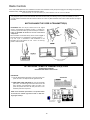
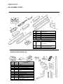
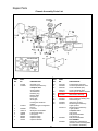
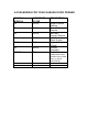
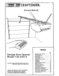
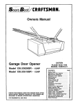
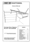
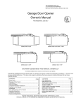
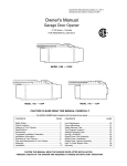
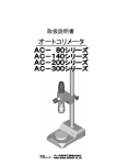
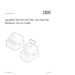
THE CHAMBERLAIN GROUP, INC. A Unit of Duchossois Industries, Inc. 845 Larch Ave., Elmhurst, Ill. 60126 Owners Manual Garage Door Opener ALL MODELS IN ARE BOLD ARE DELUXE (2 LIGHTS) 550 450 350 240 150 140 MODEL NUMBERS 550-9 450-9 350-9 240-9 150-9 140-9 250-9TV 140-9TV 550-6 450-6 350-6 240-6 150-6 140-6 140-6TV 550-9TV 500-9TV 450GM 140GM 550TV 500TV 250TV 140TV 550-6TV 500-6TV 250-6TV FEATURES OF YOUR OPENER 1. Opener Lights: Turn on and off automatically with 4-1/2 minute illumination for your safety and convenience. Provide constant LIGHT when Light Switch is ON. 5. Motor Power: Permanently lubricated motor with automatic reset. 6. Digital Radio Controls: Codes can be easily changed by the owner. 2. Safety System: Independent up and down force adjustment. The door REVERSES automatically when obstructed in DOWN direction. The door STOPS when obstructed in UP direction. 7. Easy Limit Adjustment: Limits of door opening and closing adjusted by turning screws without removing chassis cover. 3. Emergency Disconnect: Pull cord disconnect permits manual door operation. 8. Lock Switch: Prevents operation of opener from transmitter. When LOCK Switch is ON, the opener can be operated in the UP direction ONLY, from the Wall Control or optional Key Switch and Keyless Entry accessories, (See below). 4. Automatic Reconnect: Trolley halves reconnect for automatic operation when opener is energized after emergency disconnect. SPECIFICATIONS SAFETY MOTOR Type ........................................Permanent split capacitor Speed......................................1500 rpm Volts........................................120 Volts AC - 60 Hz. Only Current....................................4.5 amperes DRIVE MECHANISM Gears ......................................16:1 worm gear reduction Drive........................................Roller chain with two-piece trolley on steel Tee-rail. Length of travel........................Adjustable to 7 1/2 feet Travel rate ..............................6 to 8 inches per second Lamp .......................................On when door starts to travel, off 4 1/2 minutes after stop. Also separate LIGHT Switch. Door linkage ............................Adjustable door arm. Pull cord trolley release. 4 Personal..................................Push button and automatic reversal in down direction. Push button and Automatic stop in UP direction. Electronic................................Independent UP and DOWN force adjustment screws. Electrical .................................Motor overload protector & low voltage push button wiring. Limit device.............................Circuit actuated by limit nut Limit Adjustment .....................Screwdriver adjustment on side panel Start circuit .............................Low voltage push button or radio control. DIMENSIONS Length (overall) .......................128 inches Headroom required .................2 inches Hanging weight .......................32 pounds Adjustment STEP 1 Adjust UP and DOWN Limits LIMIT ADJUSTMENT settings regulate the points at which the door will stop when moving up or down. NOTE: Door STOPS in the UP direction if anything interferes with door travel. Door REVERSES in the DOWN direction if anything interferes with the door travel (including binding or unbalanced doors). PROCEDURE: To operate opener, press wall push button. Run the opener through a COMPLETE TRAVEL CYCLE. Limi adjustments are not necessary when the door opens and closes completely and doesn't reverse unintentionally in the fully closed position. Adjustment Label Left Side Panel Limit Adjustment Screws The following chart outlines adjustment procedures. Run the opener through a COMPLETE TRAVEL CYCLE AFTER EACH ADJUSTMENT. NOTE: REPEATED OPERATION OF THE OPENER DURING ADJUSTMENT PROCEDURES MAY CAUSE MOTOR TO OVERHEAT AND SHUT OFF. SIMPLY WAIT 15 MINUTES AND TRY AGAIN. Read chart carefully before proceeding to Step 2. Use a screwdriver to make limit adjustments. LIMIT ADJUSTMENT CHART IF ONE-PIECE DOOR DOES NOT CLOSE COMPLETELY Increase DOWN travel. Turn down limit adjustment screw COUNTERCLOCKWISE One turn equals 2 inches of travel. IF DOOR DOES NOT OPEN COMPLETELY BUT IT OPENS AT LEAST FIVE FEET Increase UP travel. Turn the UP LIMIT adjustment screw clockwise. One turn equals 2" of travel. If door does not open at least 5 feet: adjust OPEN FORCE as explained in Step 2. IF OPENER REVERSES IN FULLY CLOSED POSITION Decrease DOWN travel. Turn down limit adjustment screw clockwise. One turn equals 2" of travel. IF SECTIONAL DOOR DOES NOT CLOSE COMPLETELY Increase DOWN travel. Turn down limit adjustment screw counterclockwise. One turn equals 2" of travel. If the door still will not close completely, the header bracket is positioned too high. Repeat Step 1, page 7. IF DOOR REVERSES WHEN CLOSING AND THERE IS NO INTERFERENCE TO TRAVEL CYCLE Test door for binding: Pull emergency release handle. Manually open and close door. If door is binding, call a door serviceman. If door is not binding or unbalanced, adjust CLOSE FORCE. See Step 2. 17 STEP 2 Adjust Force DO NOT USE FORCE ADJUSTMENTS TO COMPENSATE FOR A BINDING OR STICKING GARAGE DOOR. EXCESSIVE FORCE WILL INTERFERE WITH PROPER OPERATION OF SAFETY REVERSE SYSTEM OR DAMAGE GARAGE DOOR. Force Adjustment Controls are located on rear panel of opener. FORCE ADJUSTMENT settings regulate amount of the power required to open and close door. Adjustment Force Controls NOTE: The door STOPS in the UP direction if anything interferes with its travel. Door REVERSES in the DOWN direction if anything interferes with its travel (including binding or unbalanced doors). If the force adjustments are set too light, door travel may be interrupted by nuisance reversals in DOWN direction and stops in UP direction. As weather conditions can affect the door movement, occasional adjustment may be needed. Adjsutment Label Maximum force adjustment range is 260 degrees, about 3/4 of a complete turn. Do not force controls beyond that point. Turn force adjustment controls with a screwdriver. FORCE ADJUSTMENT CHART IF DOOR DOESN'T OPEN AT LEAST 5 FEET Increase UP (OPEN) FORCE by turning clockwise. Make 10 degree turn adjustments until door opens completely. Readjust UP LIMIT if necessary. After each adjustment, run opener through a complete travel cycle. TEST DOWN (CLOSE) FORCE Grasp the door handle or door bottom when door is about halfway through DOWN (CLOSE) TRAVEL. Door should reverse. If the door is hard to hold or doesn't reverse, decrease DOWN (CLOSE) FORCE by turning the control in a counterclockwise direction. Make 10 degree turn adjustments until door reverses normally. After each adjustment, run opener through a complete cycle. PROCEED TO STEP 3 IF DOOR REVERSES DURING DOWN (CLOSE) CYCLE Increase DOWN (CLOSE) FORCE by turning control clockwise. Make 10 degree turn adjustments until door completes close cycle. After each adjustment, run the opener through a complete travel travel 17 Adjustment STEP 3 Test Safety Reverse System THE SAFETY REVERSE SYSTEM TEST IS IMPORTANT. GARAGE DOOR MUST REVERSE ON CONTACT WITH A ONE INCH OBSTACLE PLACED ON THE FLOOR. FAILURE TO PROPERLY ADJUST OPENER MAY RESULT IN SERIOUS PERSONAL INJURY FROM A CLOSING GARAGE DOOR. REPEAT TEST AT LEAST FOUR TIMES A YEAR AND ADJUST AS NEEDED.. PROCEDURE: Place a 1-inch obstacle on the floor under the garage door. Operate door in DOWN direction. The door must reverse on the obstruction. If a the door STOPS on the obstruction, it is not traveling far enough in the DOWN direction. Increase the DOWN limit by turning DOWN limit adjustment screw counterclockwise 1/4 turn. REPEAT TEST. NOTE: Make sure limit adjustments do not force the door arm beyond a straight up and down position. See the illustration on Page 13. When the door reverses on the 1-inch obstacle, remove the obstruction and run the opener through a complete travel cycle. Door MUST NOT reverse in closed position. If it does, repeat Adjustment Steps 1, 2 and 3. REPEAT ADJUSTMENT STEP 3 AFTER: • EACH ADJUSTMENT OF DOOR ARM LENGTH, CLOSE FORCE OR DOWN LIMIT. • ANY REPAIR OR ADJUSTMENT OF GARAGE DOOR (INCLUDING SPRINGS AND HARDWARE). • ANY REPAIR OR BUCKLING OF THE GARAGE FLOOR. • ANY REPAIR OR ADJUSTMENT OF THE GARAGE DOOR OPENER. (Optional) STEP 4 Install the Protector System The PROTECTOR SYSTEM provides an ADDITIONAL measure of safety against a small child being caught under a garage door. It uses an invisible beam which, when broken by an obstruction, causes a closing door to open and prevents an open door from closing. After the garage door opener has been completely installed and adjusted, the PROTECTOR SYSTEM accessory can be installed. Instructions are included with this optional device. 18 Radio Controls F.C.C. rules prohibit adjustments to or modification of receiver and/or transmitter circuitry except for changing the code setting and replacing the transmitter battery THERE ARE NO USER SERVICEABLE PARTS. Manufactured under 1 or more of the following U.S. patents: RE29,525; 4,037,201; 4,750,118; 4,806,930 Your garage door opener receiver and transmitter have been set at the factory to a matching code. If you want to CHANGE your code or purchase additional transmitter follow the instructions below. The code in any NEW transmitter must be set to match thecode in the original transmitter. MATCH/CHANGE THE CODE IN TRANSMITTER(S) PROCEDURE: With visor clip off, remove screw in the original and any new transmitter as illustrated in Figure 1. Carefully turn cases over (push button sides up). Remove case tops as shown in Figure 2. CAUTION: Be careful not to move circuit board components. Place transmitter circuit boards side by side as shown in Figure 3. Set code switches in ALL transmitters to matching positions ( +, -, or 0). Use a pen or screwdriver to slide the switches. If one transmitter has 8 code switches, set code switch 9 toe center (0) position in other transmitter. Transmitter Circuit Board Code Switches SET RECEIVER TO MATCH TRANSMITTER(S) CODE GARAGE DOOR OPENERS WITH RECEIVER SMART CODE BUTTON PROCEDURE: 1. Press the RECEIVER Smart Button on the back panel of the opener as shown. The adjacent indicator light will turn ON. TRANSMITTER 2. STAND AWAY FROM THE DOOR and press the transmitter push button. The indicator light will turn OFF and the door will move. Receiver and transmitter(s) codes now match. The opener will operate when either the wall push button or the transmitter push button is pressed. NOTE: If the transmitter push button is not pressed within 30 seconds, the indicator light will turn OFF. In that case. begin again at Step 1. 19 Repair Parts RAIL ASSEMBLY PARTS KEY NO. 1 2 3 4 5 6 7 8 9 PART NO. 1A995 41B617 41B277 12A197 183B73 183B94 183B71 41B2616 41C2735 DESCRIPTION Master link kit Outer trolley Inner trolley Chain retainer bracket Rail braces Tee rail-end section (each) Tee-rail-end section (each) Cable Pulley and bracket assy. Chain and cable NOT SHOWN 41A2848 INSTALLATION PARTS LIST KEY NO. 1 2 3 4 5 6 7 PART NO. 41D2746 10A2 41A2849 29C121-2 41A2828 217A209 41A2829 8 9 10 11 12 12B374 12B380 178B35 178B34 12B350 41A2815 114A1228 DESCRIPTION Wall control assembly 9V battery Transmitter case, cover & screw Transmitter visor cap Emergency rope & handle assy. 4-strand bell wire Header bracket w/clevis pin and ring fastener Door bracket Door bracket plate Curved door arm section Straight door arm section Hanging brackets NOT SHOWN Installation hardware bag (includes hardware illustrated on page 5) Owner’s Manual 22 Rail assy. hardware kit (includes hardware illustrated on page 5) Repair Parts Chassis Assembly Parts List KEY NO. PART NO. 1 2 31C290 41A2827 3 41A2817 4 5 6 7 8 41B2991 143D110 175B88 108D34 30B363 30B387 12A373 9 DESCRIPTION Sprocket cover Gear and sprocket assy Complete with: Spring washer Thrust washer Retaining ring Bearing plate Roll pins (2) Drive gear Worm gear Helical gear w/retainer Grease Drive/worm gear kit w/grease Roll (2) Line cord Wind panel w/all labels Light socket (each) Lens (each) Capacitor (550) Capacitor (350) Capacitor bracket KEY NO. PART NO. 10 11 12 41A3150 41D3058 41D2750 41D2751 41A2818 41D3452 41C3005 41C2726 41A3027 41A2826 41A2822 41A3519 13 14 15 16 17 18 19 20 41A3519-1 21 41A3052 41A2825 23 DESCRIPTION Terminal block w/screws Universal replacement motor Cover w/all labels (550) Cover w/all labels (350) Helical gear & retainer w/grease Limit switch assembly RPM sensor assembly Wire harness assy. w/plug Motor bracket and bearing assy. Shaft bearing kit Interrupter cup assy. Receiver logic board assy. 2 light operator Receiver logic board assy. 1 light operator Complete with: Logic board End panel w/all labels Light socket (1) End panel w/all labels NOT SHOWN Chassis assy. hardware kit (includes screws not designated by a number in illustration) CHAMBERLAIN SERVICE IS ON CALL HOW TO ORDER REPAIR PARTS OUR LARGE SERVICE ORGANIZATION SPANS AMERICA Selling prices will be furnished on request or parts will be shipped at prevailing prices and you will be billed accordingly. INSTALLATION AND SERVICE INFORMATION IS AS NEAR AS YOUR TELEPHONE SIX DAYS A WEEK. SIMPLY DIAL OUR TOLL FREE NUMBER: WHEN ORDERING REPAIR PARTS, ALWAYS GIVE THE FOLLOWING INFORMATION: • PART NUMBER • PART NAME • MODEL NUMBER 1-800-528-9131 ADDRESS ORDERS TO: THE CHAMBERLAIN GROUP, INC. Electronic Parts and Service Department 2106 N. Forbes Boulevard Tucson, Arizona 85745 HOURS: 7:00 a.m. TO 3:30 p.m. (Mountain Std. Time) MONDAY through SATURDAY FOR or professional installation, parts and service, contact your local CHAMBERLAIN dealer. Look for him in the Yellow Pages, or call our Service number for a list of dealers in your area. SERVICE INFORMATION TOLL FREE NUMBER: 1-800-528-9131 CHAMBERLAIN GARAGE DOOR OPENER ONE-YEAR LIMITED WARRANTY The Chamberlain Group warrants to the first retail purchaser of this product that it will be tree from any defect in materials and/or workmanship for a period of twelve full months from the date of purchase. The product must be used in complete accordance with Chamberlain s instructions for installation, operation and care. LIMITED WARRANTY ON MOTOR Models 550 & 550-2M: The motor is warranteed to be free from any defect in materials and/or workmanship or a period of 60 full months (5 years) from the date of purchase. Model 350: The motor is warranteed to be free from any defect in materials and/or workmanship for a period of 36 full months (3 years) from the date of purchase. This warranty does not cover non-defect damage, damage caused by unreasonable use (including abuse, failure to provide reasonable and necessary maintenance, or any alterations to the product), labor charges for dismantling or re-installing of a repaired or replaced unit or replacement batteries. If, during the warranty period, the product appears as though it may be defective, CALL OUR TOLL FREE SERVICE NUMBER BEFORE DISMANTLING IT (1-800-528-9131). If the product is then alleged to be defective, please send it prepaid and insured to our Service Center to obtain warranty repair. You will be advised of shipping instructions when you call the number listed above. Please be sure to include a brief description of the problem and a dated proof-of-purchase receipt with any product that is returned for warranty repair. Product under warranty, which upon receipt by Chamberlain is determined to be defective in materials and/or workmanship, will be repaired or replaced (Chamberlain s option) at no cost to you and returned pre-paid. Defective parts will be repaired or replaced with new or factory rebuilt parts at Chamberlains option. THE DURATION OF IMPLIED WARRANTIES OF MERCHANTABILITY AND FITNESS FOR A PARTICULAR PURPOSE IS LIMITED TO THE DURATION OF THIS WRITTEN WARRANTY. SOME STATES MAY NOT ALLOW LIMITATIONS ON HOW LONG AN IMPLIED WARRANTY LASTS, SO THE ABOVE LIMITATION MAY NOT APPLY TO YOU. All claims for consequential or incidental damages for breach of this warranty are excluded and in no event shall manufacturer s liability for breach of warranty, negligence, strict liability or breach of contract exceed this cost of the product covered herein, but the purchaser is entitled to the remedies expressly provided in this policy. Some states do not allow the exclusion or limitation of incidental or consequential damages, so the above limitation or exclusion may not apply to you. No representative or person is authorized to assume for us any other liability in connection with the sale of this product. This warranty gives you specific legal rights, and you may also have other rights which may vary from state to state. 114A1228 © 1990, The Chamberlain Group, Inc. All rights reserved Printed in Mexico ACCESSORIES FOR YOUR GARAGE DOOR OPENER ORIGINAL MODEL# 50 SUBSTITUTE TO USE 750CB 53 753CB 54 756CB 41A3685 65LM 65LM 60 760CB 1702CB 7702cb DESCRIPTION Single Function Remote Three Button Remote Mini Multi Function Remote Wall Control Panel (4 wire) Keyless Entry (Wired) Outside Keyswitch Quick Release Lock(used to open the door with no other entry, in case of power failure)